EP3490471B1 - Bone anchor housing limiter - Google Patents
Bone anchor housing limiter Download PDFInfo
- Publication number
- EP3490471B1 EP3490471B1 EP17749087.7A EP17749087A EP3490471B1 EP 3490471 B1 EP3490471 B1 EP 3490471B1 EP 17749087 A EP17749087 A EP 17749087A EP 3490471 B1 EP3490471 B1 EP 3490471B1
- Authority
- EP
- European Patent Office
- Prior art keywords
- bone
- bone anchor
- fastener
- housing
- shaft
- Prior art date
- Legal status (The legal status is an assumption and is not a legal conclusion. Google has not performed a legal analysis and makes no representation as to the accuracy of the status listed.)
- Active
Links
Images


Classifications
-
- A—HUMAN NECESSITIES
- A61—MEDICAL OR VETERINARY SCIENCE; HYGIENE
- A61B—DIAGNOSIS; SURGERY; IDENTIFICATION
- A61B17/00—Surgical instruments, devices or methods
- A61B17/56—Surgical instruments or methods for treatment of bones or joints; Devices specially adapted therefor
- A61B17/58—Surgical instruments or methods for treatment of bones or joints; Devices specially adapted therefor for osteosynthesis, e.g. bone plates, screws or setting implements
- A61B17/68—Internal fixation devices, including fasteners and spinal fixators, even if a part thereof projects from the skin
- A61B17/70—Spinal positioners or stabilisers, e.g. stabilisers comprising fluid filler in an implant
- A61B17/7001—Screws or hooks combined with longitudinal elements which do not contact vertebrae
- A61B17/7032—Screws or hooks with U-shaped head or back through which longitudinal rods pass
-
- A—HUMAN NECESSITIES
- A61—MEDICAL OR VETERINARY SCIENCE; HYGIENE
- A61B—DIAGNOSIS; SURGERY; IDENTIFICATION
- A61B17/00—Surgical instruments, devices or methods
- A61B17/56—Surgical instruments or methods for treatment of bones or joints; Devices specially adapted therefor
- A61B17/58—Surgical instruments or methods for treatment of bones or joints; Devices specially adapted therefor for osteosynthesis, e.g. bone plates, screws or setting implements
- A61B17/68—Internal fixation devices, including fasteners and spinal fixators, even if a part thereof projects from the skin
- A61B17/70—Spinal positioners or stabilisers, e.g. stabilisers comprising fluid filler in an implant
- A61B17/7001—Screws or hooks combined with longitudinal elements which do not contact vertebrae
- A61B17/7035—Screws or hooks, wherein a rod-clamping part and a bone-anchoring part can pivot relative to each other
- A61B17/7037—Screws or hooks, wherein a rod-clamping part and a bone-anchoring part can pivot relative to each other wherein pivoting is blocked when the rod is clamped
-
- A—HUMAN NECESSITIES
- A61—MEDICAL OR VETERINARY SCIENCE; HYGIENE
- A61B—DIAGNOSIS; SURGERY; IDENTIFICATION
- A61B17/00—Surgical instruments, devices or methods
- A61B17/56—Surgical instruments or methods for treatment of bones or joints; Devices specially adapted therefor
- A61B17/58—Surgical instruments or methods for treatment of bones or joints; Devices specially adapted therefor for osteosynthesis, e.g. bone plates, screws or setting implements
- A61B17/68—Internal fixation devices, including fasteners and spinal fixators, even if a part thereof projects from the skin
- A61B17/84—Fasteners therefor or fasteners being internal fixation devices
- A61B17/86—Pins or screws or threaded wires; nuts therefor
- A61B17/8605—Heads, i.e. proximal ends projecting from bone
-
- A—HUMAN NECESSITIES
- A61—MEDICAL OR VETERINARY SCIENCE; HYGIENE
- A61B—DIAGNOSIS; SURGERY; IDENTIFICATION
- A61B17/00—Surgical instruments, devices or methods
- A61B17/56—Surgical instruments or methods for treatment of bones or joints; Devices specially adapted therefor
- A61B17/58—Surgical instruments or methods for treatment of bones or joints; Devices specially adapted therefor for osteosynthesis, e.g. bone plates, screws or setting implements
- A61B17/68—Internal fixation devices, including fasteners and spinal fixators, even if a part thereof projects from the skin
- A61B17/84—Fasteners therefor or fasteners being internal fixation devices
- A61B17/86—Pins or screws or threaded wires; nuts therefor
- A61B17/8625—Shanks, i.e. parts contacting bone tissue
- A61B17/863—Shanks, i.e. parts contacting bone tissue with thread interrupted or changing its form along shank, other than constant taper
-
- A—HUMAN NECESSITIES
- A61—MEDICAL OR VETERINARY SCIENCE; HYGIENE
- A61B—DIAGNOSIS; SURGERY; IDENTIFICATION
- A61B17/00—Surgical instruments, devices or methods
- A61B17/56—Surgical instruments or methods for treatment of bones or joints; Devices specially adapted therefor
- A61B17/58—Surgical instruments or methods for treatment of bones or joints; Devices specially adapted therefor for osteosynthesis, e.g. bone plates, screws or setting implements
- A61B17/68—Internal fixation devices, including fasteners and spinal fixators, even if a part thereof projects from the skin
- A61B17/84—Fasteners therefor or fasteners being internal fixation devices
- A61B17/86—Pins or screws or threaded wires; nuts therefor
- A61B17/8625—Shanks, i.e. parts contacting bone tissue
- A61B17/8635—Tips of screws
-
- A—HUMAN NECESSITIES
- A61—MEDICAL OR VETERINARY SCIENCE; HYGIENE
- A61B—DIAGNOSIS; SURGERY; IDENTIFICATION
- A61B17/00—Surgical instruments, devices or methods
- A61B17/56—Surgical instruments or methods for treatment of bones or joints; Devices specially adapted therefor
- A61B17/58—Surgical instruments or methods for treatment of bones or joints; Devices specially adapted therefor for osteosynthesis, e.g. bone plates, screws or setting implements
- A61B17/68—Internal fixation devices, including fasteners and spinal fixators, even if a part thereof projects from the skin
- A61B17/84—Fasteners therefor or fasteners being internal fixation devices
- A61B17/86—Pins or screws or threaded wires; nuts therefor
- A61B17/8685—Pins or screws or threaded wires; nuts therefor comprising multiple separate parts
-
- A—HUMAN NECESSITIES
- A61—MEDICAL OR VETERINARY SCIENCE; HYGIENE
- A61B—DIAGNOSIS; SURGERY; IDENTIFICATION
- A61B17/00—Surgical instruments, devices or methods
- A61B17/56—Surgical instruments or methods for treatment of bones or joints; Devices specially adapted therefor
- A61B17/58—Surgical instruments or methods for treatment of bones or joints; Devices specially adapted therefor for osteosynthesis, e.g. bone plates, screws or setting implements
- A61B17/68—Internal fixation devices, including fasteners and spinal fixators, even if a part thereof projects from the skin
- A61B17/84—Fasteners therefor or fasteners being internal fixation devices
- A61B17/86—Pins or screws or threaded wires; nuts therefor
- A61B17/8695—Washers
-
- A—HUMAN NECESSITIES
- A61—MEDICAL OR VETERINARY SCIENCE; HYGIENE
- A61B—DIAGNOSIS; SURGERY; IDENTIFICATION
- A61B17/00—Surgical instruments, devices or methods
- A61B17/56—Surgical instruments or methods for treatment of bones or joints; Devices specially adapted therefor
- A61B2017/564—Methods for bone or joint treatment
-
- A—HUMAN NECESSITIES
- A61—MEDICAL OR VETERINARY SCIENCE; HYGIENE
- A61B—DIAGNOSIS; SURGERY; IDENTIFICATION
- A61B17/00—Surgical instruments, devices or methods
- A61B17/56—Surgical instruments or methods for treatment of bones or joints; Devices specially adapted therefor
- A61B17/58—Surgical instruments or methods for treatment of bones or joints; Devices specially adapted therefor for osteosynthesis, e.g. bone plates, screws or setting implements
- A61B17/68—Internal fixation devices, including fasteners and spinal fixators, even if a part thereof projects from the skin
- A61B17/84—Fasteners therefor or fasteners being internal fixation devices
- A61B17/86—Pins or screws or threaded wires; nuts therefor
- A61B2017/8655—Pins or screws or threaded wires; nuts therefor with special features for locking in the bone
-
- A—HUMAN NECESSITIES
- A61—MEDICAL OR VETERINARY SCIENCE; HYGIENE
- A61B—DIAGNOSIS; SURGERY; IDENTIFICATION
- A61B17/00—Surgical instruments, devices or methods
- A61B17/56—Surgical instruments or methods for treatment of bones or joints; Devices specially adapted therefor
- A61B17/58—Surgical instruments or methods for treatment of bones or joints; Devices specially adapted therefor for osteosynthesis, e.g. bone plates, screws or setting implements
- A61B17/68—Internal fixation devices, including fasteners and spinal fixators, even if a part thereof projects from the skin
- A61B17/84—Fasteners therefor or fasteners being internal fixation devices
- A61B17/86—Pins or screws or threaded wires; nuts therefor
- A61B17/8665—Nuts
- A61B2017/867—Nuts with integral locking or clamping means
-
- A—HUMAN NECESSITIES
- A61—MEDICAL OR VETERINARY SCIENCE; HYGIENE
- A61B—DIAGNOSIS; SURGERY; IDENTIFICATION
- A61B90/00—Instruments, implements or accessories specially adapted for surgery or diagnosis and not covered by any of the groups A61B1/00 - A61B50/00, e.g. for luxation treatment or for protecting wound edges
- A61B90/06—Measuring instruments not otherwise provided for
- A61B2090/061—Measuring instruments not otherwise provided for for measuring dimensions, e.g. length
Definitions
- This document pertains generally, but not by way of limitation, to systems and methods for fixation of bones during orthopedic procedures. More particularly, this disclosure relates to, but not by way of limitation, vertebral bone anchors particularly suited for use in weakened or degenerative bone.
- the spinal column of a patient includes a plurality of vertebrae linked to one another by facet joints and an intervertebral disc located between adjacent vertebrae.
- the facet joints and intervertebral disc allow one vertebra to move relative to an adjacent vertebra, providing the spinal column a range of motion.
- Diseased, degenerated, damaged, or otherwise impaired facet joints and/or intervertebral discs may cause the patient to experience pain or discomfort and/or loss of motion, thus prompting surgery to alleviate the pain and/or restore motion of the spinal column.
- One possible method of treating these conditions is to immobilize a portion of the spine to allow treatment.
- immobilization has been accomplished by rigid stabilization.
- a surgeon restores the alignment of the spine or the disc space between vertebrae by installing a rigid fixation rod between pedicle screws secured to adjacent vertebrae. Bone graft is placed between the vertebrae, and the fixation rod cooperates with the screws to immobilize the two vertebrae relative to each other so that the bone graft may fuse with the vertebrae.
- Dynamic stabilization has also been used in spinal treatment procedures. Dynamic stabilization does not result in complete immobilization, but instead permits a degree of mobility of the spine while also providing sufficient support and stabilization to effect treatment. Dynamic stabilization systems can include a flexible construct extending between pedicle screws installed in adjacent vertebrae of the spine.
- stabilization systems are the Dynesys ® System, the Sequoia ® Thoracolumbar Pedicle Screw System and the Lineum ® OCT Spine System available from Zimmer Biomet Spine, Inc. of Broomfield, Colorado.
- WO 2010/111470 discloses a variable height, multi-axial bone screw assembly
- WO 2011/056707 discloses a multiplanar bone anchor system
- US 2005/273101 is concerned with a bone screw and osteosythesis device for fixing at least two bone parts relate to one another in a fixation position
- GB 2 512 063 discloses a spinal implant assembly comprising an intervertebral device
- WO 2006/104709 discloses stabilizer for a bone anchor includes a tubular body.
- a problem to be solved can include the need to provide bone anchors, such as threaded fasteners or screws, in bone that is degenerative or otherwise weakened. If bone anchors are inserted into weakened bone, there can be the potential for the fastener to move position or become dislodged, thereby rendering the anchoring effects provided by the fastener less effective or altogether ineffective.
- bone anchors such as threaded fasteners or screws
- the present subject matter can help provide a solution to various problems associated with the anchoring of fasteners in weakened or partially weakened bone by providing a sizing component that can be coupled to the fastener to enlarge the anchoring footprint of the fastener.
- the sizing component can be modular such that it can be attached to standard fasteners already typically maintained in inventory and/or can be combined with other sizing components to change the capabilities of the sizing component. Additionally, various sizing components can come in different shapes and configurations to accommodate bone that is weakened or degenerative in different capacities, thereby allowing a practitioner or surgeon the ability to choose from a variety of sizing components for use with particular bone defects of a particular patient.
- the sizing component can be a sleeve into which a fastener is threaded to enlarge all or part of the shaft diameter of the fastener to provide radial anchoring in cancellous bone inside the bone, or a cap into which a fastener is threaded to provide axial anchoring into cortical bone at a surface of the bone.
- the present subject matter can help provide a solution to this problem, such as by providing a bone anchor system that can comprise: a fastener, a rod housing and a first directional component.
- a bone anchor system that can comprise: a fastener, a rod housing and a first directional component.
- a bone anchor system according to the invention is defined in claim 1, while preferred embodiments are set forth in the dependent claims.
- the fastener comprises: a shaft having a shaft diameter; an anchoring projection, such as threading, on the shaft; and a head at an end of the shaft.
- a rod housing is connected to the head of the fastener.
- a first directional component is configured for connection to the fastener.
- the first directional component comprises: a first body portion having a first outer diameter larger than the shaft diameter; a first bore extending through the first body portion, the first bore sized to receive the shaft diameter; and a first locking component extending from the first body portion configured to engage one or more exterior surfaces of the rod housing to limit movement of the housing.
- a bone anchor directional component can comprise a first body portion, a first bore and a first locking component.
- the first body portion can have a first outer diameter larger than the shaft diameter.
- the first bore can extend through the first body portion and can be sized to receive a shaft of a bone anchor.
- the first locking component can extend from the first body portion and can be configured to engage a rod housing of the bone anchor to limit movement of the housing relative to a fastener shaft.
- FIG. 1 is an exploded view illustrating components of exemplary bone anchor 10 and rod 12.
- Bone anchor 10 can include closure member 11, retainer assembly 13, fastener 20 and housing 30.
- Retainer assembly 13 can include retainer ring 14, wave washer 15 and seat 16.
- Fastener 20 can include head 21, keyed portion 22 and shank 23.
- Housing 30 can include upper housing 40 and lower housing 50.
- Upper housing 40 can include opposing arms 41, threading 42 and U-shaped channel 43, which extends along a transverse axis that is transverse to the axial axis of fastener shank 23.
- FIG. 2 is a perspective view of bone anchor 10 of FIG. 1 showing rod 12 secured to housing 30 between fastener 20 and closure member 11. FIGS. 1 and 2 are discussed concurrently.
- Bone anchor 10 can be used to couple rod 12 or another elongate member to a boney structure.
- shank 23 of fastener 20 can be inserted into and through upper housing 40 and lower housing 50 to connect to a pedicle of a vertebra.
- Retainer assembly 13 can be inserted into channel 43 to sit below rod 12.
- Retainer ring 14 can be connected to upper housing 40 to lock wave washer 15 and seat 16 in housing 30 below threading 42, thereby at least partially immobilizing fastener 20 within housing 30.
- Rod 12 can fit into U-shaped channel 43 formed by opposing arms 41, such as by being inserted into channel 43 from the top or proximal end of housing 30.
- Closure member 11, which can comprise a set screw or the like, can be threaded into threading 42 to push rod 12 down into channel 43 atop retainer assembly 13, thereby at least partially immobilizing rod 12 within bone anchor 10.
- Bone anchor 10 can include particular degrees of adjustability that can help ensure that fastener 20 and elongate member 12 can be locked down at the particular locations and orientations desired by the practitioner or surgeon.
- head 21 can be spherical in shape to allow rotation within housing 30.
- bone anchor 10 can allow for angular deviation of bone screw 20 away from the axial orientation shown in FIG. 1 .
- Such an angular deviation may be referred to as "angulation”, and desired angulations may exceed 35 degrees, 40 degrees, 45 degrees, or more, in some instances. Further description of such angulation is described in U.S. Pat. No. 9,289,244 to Hestad et al. .
- Bone anchor 10 can be delivered or provided to or obtained by a practitioner in a semi-assembled state.
- housing 30 can be modular, thus formed of multiple components coupled together.
- housing 30 can include two components that are longitudinally adjacent to each other, namely upper housing 40 and lower housing 50.
- upper housing 40 and lower housing 50 can be pre-assembled.
- fastener 20 can be pre-inserted into housing 30.
- Housing 30 can have a bore that extends longitudinally through the upper housing 40 and lower housing 50, generally coaxial with the longitudinal axis of bone anchor 10.
- Upper housing can include bore 46 and lower housing 50 can include bore 52 which can each be aligned and centered along the central axial axis of fastener 20 when fastener 20 is assembled with housing 30.
- Fastener 20 can have threaded shank 23 that extends out from the bottom of lower housing 50 at bore 52 after passing through bore 46.
- Head 21 can be sized such that head 21 can pass into bore 46, but cannot pass through bore 52.
- Head 21 of fastener 20 can be generally spherical in shape, so that it may pivot with respect to housing 30 on lower housing 50.
- shank 23 Prior to final assembly, shank 23 can be dropped downward or otherwise inserted into the top of housing 30 through upper housing 40 and lower housing 50 so that head 21 can rest on lower housing 50.
- fastener 20 can be bottom-loaded into upper housing 40, and then lower housing 50 can be positioned around shank 23 and coupled onto upper housing 40, so that head 21 can be held in place within upper housing 40 atop lower housing 50.
- Head 21 of fastener 20 can be held in place by retainer assembly 13, which can prevent fastener 20 from being pulled upward out of or otherwise displaced from housing 30.
- Retainer assembly 13 can allow pivoting of screw head 21 with respect to housing 30.
- Retainer assembly 13 can be typically in the form of one or more rings having a central aperture, which can allow the practitioner to insert a screwdriver through the apertures of the rings to engage a driver interface such as a keyed portion 22 on head 21 of fastener 20.
- the exemplary retainer assembly 13 in FIG. 1 can include seat 16 that can contact head 21, biasing member or wave washer 15, and retainer ring 14 farthest away from screw head 21.
- Seat 16 can include a concave annular region that has a radius of curvature matched to that of screw head 21, which facilitates pivoting of head 21.
- the concave annular region can also increase the frictional contact with head 21, which facilitates fastener 20 being held in place by seat 16 in the desired angular orientation.
- Biasing member 15 can be inserted into channel 43 so as to be disposed on top of seat 16.
- Retainer ring 14 can be coupled to housing 30, such as via split-ring configuration, to secure biasing member 15 between seat 16 and retainer ring 14.
- biasing member 15 and retainer ring 14 can fit around an annular portion of seat 16.
- rod 12 can be positioned on top of retainer ring 14.
- closure member 11 can screw closure member 11 into threads 42 at the upper portion of housing 30 until closure member 11 engages rod 12.
- Closure member 11 can force rod 12 against the upper surface of seat 16, pushing retainer ring 14 and biasing member 15 down around seat 16, and in turn can force seat 16 against head 21 of the screw 20.
- biasing member 15 Prior to final tightening of closure member 11, biasing member 15 can cause seat 16 to frictionally engage head 21 to resist movement of housing 30 with respect to fastener 20, which can allow for repositioning of shank 23.
- the frictional force between seat 16 of retainer assembly 13 and head 21 can be sufficient to lock fastener 20 in place with respect to housing 30.
- U-shaped channel 43 can be deep enough so that closure member 11 does not force rod 12 against the bottom of U-shaped channel 43, with rod 12 being immobilized between seat 16 and closure member 11.
- retainer assembly 13 can be omitted, and closure member 11 can force rod 12 directly against head 21 of fastener 20 to secure fastener 20 in place.
- closure member 11 can push rod against portions of arms 41 forming the bottom of channel 43 to immobilize rod 12, with or without retainer assembly 14.
- angulation of fastener 20 can be partially immobilized by biasing member 15, and in such an example without retainer assembly 14 fastener 20 can be freely angulated (e.g. is not immobilized).
- fastener 20 is threaded into bone that is structurally sound such that bone anchor 10 is substantially immobilized via engagement of threading on shank 23 extending radially from shank 23 into cancellous bone.
- bone at a location where it is desirable to provide anchoring by bone anchor 10 is inadequate for immobilizing a fastener.
- Such inadequate bone can arise from a variety of conditions, such as osteoporosis or other degenerative conditions that cause the bone structure to become compromised and weakened.
- the present disclosure addresses these issues in anchoring fasteners in boney structure by providing a sizing component that can be coupled to the fastener to increase the anchoring capacity or footprint of the fastener to reach a larger area and thereby reach healthy or otherwise structurally sound bone for anchoring.
- FIG. 3 is a perspective view of exemplary bone anchor 60 having sizing component 62, which can comprise threaded sleeve 64, enlarging threading 66, first end 68, second end 70 and central bore 72.
- Bone anchor 60 can comprise fastener 74 and housing 76.
- Fastener 74 can include shaft 78, which can include anchor threading 80.
- Bone anchor 60 can function similarly to that of bone anchor 10 of FIG. 1 .
- fastener 74 can include spherical head 82 that can rotate within housing 76, which can include slot 84 for receiving a rod.
- Sizing component 62 can be sized to mate with shaft 78 of fastener 74.
- the outer diameter of shaft 78 can be sized to fit within the diameter of central bore 72, and internal female threading ("sizing threading") within central bore 72 can be sized to mate with male anchor threading 80.
- Sizing component 62 can be configured to operate with other bone anchor devices, such as bone anchor 200 of FIGS. 7-9 .
- Sleeve 64 can extend along a central axis that is configured to be co-axial with the central axis of shaft 78.
- Sleeve 64 can be tapered between first end 68 and second end 70 in order to provide a smooth transition between the outer diameter of shaft 78 and the outer diameter of sleeve 64.
- First end 68 of sleeve 64 can have a diameter of the desired outer diameter of sizing component 62.
- the diameter of first end 68 can be selected to increase the diameter of shaft 78 by any desirable amount to provide a larger anchoring footprint, as discussed below.
- Second end 70 can have a diameter that is just slightly larger than the outer diameter of shaft 78 sufficient to allow insertion of shaft 78 into sleeve 64.
- the diameter of sleeve 64 can increase from second end 70 to first end 68 so that, as shaft 78 is threaded into bone, sizing component 62 can be eased or gradually inserted into the bore in the bone.
- the diameter of sleeve 64 need not increase in a steady manner such that the widest portion of sleeve 64 need not be located at first end 68.
- Enlarging threading 66 on sleeve 64 can be sized to be the same as anchor threading 80 on shaft 78.
- threading 66 on sleeve 64 can have the same pitch as threading 80 on shaft 78 to facilitate smooth entry of fastener 74 into a bone bore, particularly one that is pre-tapped with threading.
- anchor threading 80 and enlarging threading 66 can have the same pitch, but with different diameters, to ensure fastener 74 and sizing component 62 advance into the bone at the same rate and prevent binding.
- threading 66 can comprise a continuation of threading 80 that in aggregate extends from tip 86, along shaft 78, onto second end 70, increasing in size along sleeve 64 and to first end 68.
- threading 66 can be dual lead and threading 80 can be single lead with double pitch and have larger valleys to provide deep anchoring in the bone structure, as is discussed in greater detail with reference to FIG. 13 .
- Sizing component 62 can comprises sleeve 64 that can enlarge the diameter of shaft 78.
- the outer diameter of sleeve 64 and threading 66 can radially increase the diameter of bone anchor 60 to allow shaft 78 to increase or enlarge the anchoring footprint of fastener 74.
- shaft 78 can be configured to anchor bone anchor 60 into a bone bore having approximately the same diameter as shaft 78.
- the boney structure may be weakened or deficient such that threads 80 cannot take adequate hold in the boney structure, thereby leaving open the possibility of bone anchor 60 becoming dislodged or displaced.
- Sleeve 64 can enlarge shaft 78 such that bone anchor 60 can become engaged in bone outside of, or larger than, the diameter of shaft 78.
- sleeve 64 can be selected to have an outer diameter that is larger than a diseased or weakened bone area surrounding a bone bore into which shaft 78 is threaded.
- threading 66 of sleeve 64 can provide anchoring in healthy or structurally sound bone material.
- Sleeve 64 can be threaded onto shaft 78 up to the proximal end of threading 80 near spherical head 82. As such, sleeve 64 can be configured to overcome deficient boney structure proximate a cortical bone surface surrounding the bone bore. Additionally, sleeve 64 can provide strengthening of shaft 78 near spherical head 82 in a location that can sometimes be subjected to stress during installation and use. The axial length of sleeve 64 allows sizing component 62 to engage healthy cancellous bone, displacing any weak or unhealthy cancellous bone. As discussed below, shaft 78 can be provided with a stop or locking feature (e.g. stop 248 of FIG. 11 ) to prevent sleeve 64 from backing out of the bone bore and protruding beyond the cortical bone.
- a stop or locking feature e.g. stop 248 of FIG. 11
- the diameter of sleeve 64 can vary in different embodiments of sizing component 62.
- the length of sizing component 62 between first end 68 and second end 79 can vary in different embodiments of sizing component 62.
- a variety of sizing components 62 can be provided in inventory, such as in a system, set, kit or package, or as part of a surgical system, to allow a surgeon or practitioner to intra-operatively select one or more sizing components of desired length and diameter, or material to compensate for or overcome weakened or defective boney structure at a particular surgical site of a patient at a location where the procedure is performed.
- FIG. 4 is a perspective view of exemplary bone anchor 60 having sizing component 90, which can comprise cap 92 having axial fixation teeth 94 and central bore 96.
- Bone anchor 60 can be configured in the same manner as described with reference to FIG. 3 and can function similarly as bone anchor 10 of FIGS. 1 and 2 .
- Bone anchor 60 can comprise fastener 74 and housing 76, which includes slot 84.
- Fastener 74 can include shaft 78, which can include threading 80, head 82 and tip 86.
- Sizing component 90 can be sized to mate with shaft 78 of fastener 74.
- the outer diameter of shaft 78 can be sized to fit within the diameter of central bore 96, and internal threading within central bore 96 can be sized to mate with threading 80.
- Sizing component 90 can be configured to operate with other bone anchor devices, such as bone anchor 200 of FIGS. 7-9 .
- Cap 92 can extend along a central axis that is configured to be co-axial with the central axis of shaft 78.
- Cap 92 can have an octagonal or hexagonal outer perimeter surface shape in order to engage a driver device. As such, insertion and removal of sizing component 90 can be facilitated with an instrument such as an open end wrench.
- the shape of the outer perimeter of cap 92 can have other configurations, such as square or circular.
- Cap 92 can have an outer perimeter size selected to increase the diameter or size of shaft 78 any desirable amount to provide a larger anchoring footprint, as discussed below.
- fixation teeth 94 can extend from rim 98 to engage cortical bone surrounding shaft 78.
- Rim 98 can comprise a flange that can extend radially and/or axially from cap 92 to position fixation teeth 94 for engaging bone.
- Fixation teeth 94 can extend axially from rim 98 in a distal direction away from cap 92.
- Fixation teeth 94 can have a circumferential orientation to facilitate insertion into the cortical bone as sizing component 90 is rotated.
- fixation teeth 94 can be oriented in a clockwise circumferential direction when viewed from the proximal end of shaft 78 near spherical head 84 (as depicted in FIG. 4 ) to facilitate insertion of fixation teeth 94 when cap 92 is rotated in a clockwise or right-hand thread direction.
- fixation teeth 94 can have different shapes or can be replaced with textured or jagged surfaces along rim 98 for engaging bone.
- cap 92 As cap 92 is threaded onto shaft 78, the outer size of cap 92 can radially increase the diameter of bone anchor 60 to allow shaft 78 to increase or enlarge the anchoring footprint of fastener 74.
- shaft 78 can be configured to anchor bone anchor 60 into a bone bore having approximately the same diameter as shaft 78.
- the boney structure may be weakened or deficient such that threads 80 cannot take adequate hold in the boney structure, thereby leaving open the possibility of bone anchor 60 becoming dislodged or displaced.
- Cap 92 can enlarge shaft 78 such that bone anchor 60 can become engaged in bone outside of, or larger than, the diameter of shaft 78.
- cap 92 can be selected to have an outer size that is larger than a diseased or weakened bone area surrounding a bone bore into which shaft 78 is threaded.
- fixation teeth 94 of cap 92 can provide anchoring in healthy or structurally sound bone material that surrounds the bone bore.
- Cap 92 can be threaded onto shaft 78 up to the proximal end of threading 80 near spherical head 82. As such, cap 92 can be configured to overcome deficient boney structure proximate a cortical bone surface surrounding the bone bore. Shaft 78 continues to provide anchoring within the bone bore in cancellous bone. As discussed below, shaft 78 can be provided with a stop feature (e.g. stop 248 of FIG. 11 ) to prevent cap 92 from backing out from engagement with the cortical bone.
- a stop feature e.g. stop 248 of FIG. 11
- the diameter of cap 92 can vary in different embodiments of sizing component 90.
- the shape, such as the length, of fixation teeth 94 can vary in different embodiments of sizing component 90.
- a variety of sizing components 90 can be provided in inventory, such as in a system, set, kit or package, or as part of a surgical system, to allow a surgeon or practitioner to intra-operatively select one or more sizing components of desired length and diameter to compensate for or overcome weakened or defective boney structure at a particular surgical site of a patient at a location where the procedure is performed.
- FIG. 5 is a perspective view of exemplary bone anchor 60 having sizing component 100, which can be configured similarly as sizing component 90 of FIG. 4 with the addition of extension sleeve 102.
- Sizing component 100 can also include cap 92, axial fixation teeth 94, central bore 96 and rim 98.
- Extension sleeve 102 can include threading 104.
- Bone anchor 60 can be configured in the same manner as described with reference to FIG. 3 and can function similarly as bone anchor 10 of FIGS. 1 and 2 .
- Bone anchor 60 can comprise fastener 74 and housing 76, which includes slot 84.
- Fastener 74 can include shaft 78, which can include threading 80, head 82 and tip 86.
- Cap 92 can function similarly as described with reference to FIG. 4 .
- Extension sleeve 102 and threading 104 can function similarly as threaded sleeve 64 and threading 66 of sizing component 62 of FIG. 3 .
- FIG. 5 depicts a combination of the embodiments of FIGS. 3 and 4 wherein first end 68 of threaded sleeve 64 extends from cap 92.
- Extension sleeve 102 can extend from cap 92 along a central axis that is configured to be co-axial with the central axis of shaft 78. Extension sleeve 102 can be tapered between cap 92 and distal end 106 in order to provide a smooth transition between the outer diameter of shaft 78 and the outer diameter of sleeve extension 102. The diameter of extension sleeve 102 can be selected to increase the diameter of shaft 78 any desirable amount to provide a larger anchoring footprint, as discussed herein. Distal end 106 can have a diameter that is just slightly larger than the outer diameter of shaft 78 sufficient to allow insertion of shaft 78 into extension sleeve 102.
- extension sleeve 102 can be tapered so that, as shaft 78 is threaded into bone, sizing component 100 can be eased or gradually inserted into the bore in the boney structure.
- Threading 104 on extension sleeve 102 can be sized to be the same as threading 80 on shaft 78.
- threading 104 on extension sleeve 102 can have the same pitch as threading 80 on shaft 78 to facilitate advancement into the boney structure at the same rate and prevent binding.
- Sizing component 100 can comprises extension sleeve 102 that can be larger than the diameter of shaft 78, and cap 92 that can be larger than the diameter of extension sleeve 102.
- the outer diameter of extension sleeve 102 and threading 104 can effectively radially increase the diameter of shaft 78 to increase or enlarge the anchoring footprint of fastener 74, while cap 92 can further increase the size of the anchoring footprint.
- extension sleeve 102 can increase the anchoring footprint in the radial and axial directions to engage cancellous bone in a bone bore, while cap 92 and fixation teeth 94 can increase the anchoring footprint in the radial and axial directions to engage cortical bone.
- extension sleeve 102 can displace weak or unhealthy cancellous bone to engage healthy cancellous bone, while fixation teeth 94 can be extended radially beyond weak or unhealthy cortical bone to axially engage healthy cortical bone.
- extension sleeve 102 has a length sized to only engage cancellous bone near the cortical surface of a bone bore.
- extension sleeve 102 can be sized to extend along substantially all of shaft 78.
- FIG. 6 is a perspective view of exemplary bone anchor 60 having sizing component 110, which can be configured similarly as sizing component 100 of FIG. 4 with the addition of extension sleeve 102 having a greater length.
- Sizing component 110 can also include cap 92, axial fixation teeth 94, central bore 96 and rim 98.
- Extension sleeve 102 can include threading 104.
- Bone anchor 60 can be configured in the same manner as described with reference to FIG. 3 and can function similarly as bone anchor 10 of FIGS. 1 and 2 .
- Bone anchor 60 can comprise fastener 74 and housing 76, which includes slot 84.
- Fastener 74 can include shaft 78, which can include threading 80, head 82 and tip 86.
- sizing component 110 can be configured to operate in the same or a similar fashion as sizing component 100 of FIG. 5 except extension sleeve 102 is longer to engage a greater quantity of cancellous bone.
- distal end 106 can be positioned further down into a bone bore and the length of extension sleeve 102 can be used to displace a greater length of cancellous bone to allow threading 104 to engage a greater quantity of healthy cancellous bone.
- Sleeve 102 can extend across substantially all of shaft 78 except for the distal tapered end portion where tip 86 is located.
- FIG. 7 is a side view of exemplary bone anchor 200 having sizing component 202 comprising threaded sleeve 204.
- FIG. 8 is a cross-sectional view of bone anchor 200 and sizing component 202 of FIG. 7.
- Threaded sleeve 204 can also comprise male anchor threading 206, first end 208, second end 210 and central bore 212 with female sizing threading 213.
- Bone anchor 200 can comprise fastener 214, which can include head 216, shaft 218, threading 220 and socket 222.
- Bone anchor 200 can function similarly as bone anchor 10 of FIG. 1 and bone anchor 60 of FIG. 3 , except bone anchor 200 includes head 216 instead of spherical head 82. As such, bone anchor 200 is not configured for use with housing 76 ( FIG. 3 ). Instead, head 216 can be used with other components, such as plates, fusion systems, intra vertebral spacers and the like. Head 216 can be cylindrical for receding into another component. Head 216 can include socket 22 for receiving a drive tool, such as a screw driver or hex head wrench. In any event, fastener 214 can be used to secure bone anchor 200 to a boney structure.
- a drive tool such as a screw driver or hex head wrench.
- Sizing component 202 can function similarly as sizing component 60 of FIG. 3 .
- sizing component 202 can have first end 208 and second end 210, with threaded sleeve 204 being tapered there-between to facilitate smooth insertion into bone.
- Threading 206 can be sized to match threading 220 of shaft 218 of fastener 214. In other words, threading 206 and threading 220 can have the same pitch to ensure fastener 214 and sizing component 202 advance into the boney structure at the same rate and prevent binding.
- Sleeve 204 can extend along a central axis that is configured to be co-axial with the central axis of shaft 218.
- Sleeve 204 of sizing component 202 can enlarge the diameter of shaft 218 to radially increase the diameter of bone anchor 200 to allow shaft 218 to increase or enlarge the anchoring footprint of fastener 214.
- shaft 218 can be configured to anchor bone anchor 200 into a bone bore having approximately the same diameter as shaft 218.
- the boney structure may be weakened or deficient such that threads 220 cannot take adequate hold in the boney structure, thereby leaving open the possibility of bone anchor 200 becoming dislodged or displaced.
- Sleeve 204 can enlarge shaft 218 such that bone anchor 200 can become engaged in bone outside of, or larger than, the diameter of shaft 218.
- sleeve 204 can be selected to have an outer diameter that is larger than a diseased or weakened bone area surrounding a bone bore into which shaft 218 is threaded.
- threading 206 of sleeve 204 can provide anchoring in healthy or structurally sound bone material.
- Sleeve 204 can be threaded onto shaft 218 up to the proximal end of threading 220 near head 216.
- sleeve 204 can be configured to overcome deficient boney structure proximate a cortical bone surface surrounding the bone bore, and can be used to strengthen shaft 218.
- the axial length of sleeve 204 allows sizing component 202 to engage healthy cancellous bone, displacing any weak or unhealthy cancellous bone.
- the sizes, e.g. length and diameter, of sleeve 204 can vary in different embodiments of sizing component 202 to permit a variety of sizing components 202 to be provided in inventory, such as in a system, set, kit or package, or as part of a surgical system, to allow a surgeon or practitioner to intra-operatively select one or more sizing components of desired length and diameter to compensate for or overcome weakened or defective boney structure at a particular surgical site of a patient at a location where the procedure is performed.
- first end 208 can include countersink or socket 224, which can allow for multiple sizing components 202 to be used in conjunction with each other to increase the axial anchoring footprint of sizing component 202, as shown in FIGS. 9 and 10 .
- socket 224 can be omitted from sizing component 202 to, for example, provide additional contact with the threaded fastener.
- FIG. 9 is a side view of first sizing component 202A, such as sizing component 200 shown in FIGS. 7 and 8 , axially abutted with second sizing component 202B of similar construction.
- FIG. 10 is a cross-sectional view of first and second sizing components 202A and 202B of FIG. 9. FIGS. 9 and 10 are discussed concurrently.
- Sizing component 202A can include threaded sleeve 204A having threading 206A, first end 208A, second end 210A, central bore 212A, sizing threading 213A and socket 224A.
- Sizing component 202B can include threaded sleeve 204B having threading 206B, first end 208B, second end 210B, central bore 212B, sizing threading 213B and socket 224B.
- second ends 210A and 210B can be tapered to provide smooth transitions with shaft 218 of fastener 214.
- Sockets 224A and 224B can be shaped in the mirror images of the tapers of second ends 210A and 210B to allow the tapering to be fully recessed into sockets 224A and 224B.
- socket 224B can receive all or nearly all of the tapering of second end 210A such that there is no change in the diameter of the joined sizing components 202A and 202B between sleeves 204A and 204B at junction 226.
- Sockets 224A and 224B can include threading 228A and 228B, respectively to receive threading of a mating sizing component.
- socket 224B of sizing component 202B can include threading 228B to receive threading 206A of sizing component 202A.
- multiple sizing components 202 can be axially stacked together to increase the effective length of the sizing component. This can reduce the number and variety of different sizing components needed in inventory to form different systems, sets, kits and packages as described herein.
- FIG. 11 is a cross-sectional view of a portion of fastener 214 of FIG. 8 having stop 248 and an exemplary sizing component 250 having cap 252 with axial fixation teeth 254 and sleeve 256.
- Sizing component 250 can also include central bore 258 and rim 260.
- Sizing component 250 is similar to sizing component 100 of FIG. 5 , except being particularly sized for use with fastener 214.
- central bore 258 can be sized to receive the diameter of shaft 218 of fastener 214, and central bore 258 can include female sizing threading 262 to receive male anchor threading 220 of shaft 218.
- any of the sizing components described herein can have different dimensions in different embodiments for use with a variety of different fasteners and bone anchors.
- Cap 252 can be shaped to have surfaces to engage a drive tool, such as a wrench or the like.
- Rim 260 can extend from cap 252 to position teeth 254 radially outward of sleeve 256. Rim 260 can extend radially outward from cap 252 and axially away from cap 252. Teeth 254 can extend axially from rim 260 to provide axial anchoring in bone surrounding fastener shaft 218.
- Sleeve 256 can extend axially from cap 252 within teeth 254. Sleeve 256 increases the diameter of shaft 218 such that threading 266 of sleeve 256 can increase the anchoring footprint of fastener 214 beyond what is provided by threading 220.
- Sleeve 256 and threading 266 can be shaped to smoothly mate with shaft 218 and threading 220.
- sleeve 256 can be tapered to allow for a smooth entry of shaft 218 and sizing component 250 into a bone bore.
- threading 266 can have the same pitch as threading 220 to allow for entry of shaft 218 and sizing component 250 into a bone bore without binding.
- the various embodiments and examples of sizing components described herein can be made of a variety of different materials in different embodiments.
- the sizing components can be made of porous metal or biocompatible metal or alloys.
- the sizing components can be made from titanium or Trabecular Metal TM , which is commercially available from Zimmer Inc.
- the sizing components can be made of a polymer, such as polyether ether ketone (PEEK).
- PEEK polyether ether ketone
- the sizing components can be made of autograft or allograft bone.
- FIG. 12 is a flow chart diagramming method 300 of implanting a sizing component of the present application.
- Method 300 can include the steps of forming a bone bore in a boney structure 302, tapping the bone bore 304, trialing the bone bore 306, selecting a sizing component for use in the bone bore 308, assembling the sizing component with a fastener 310, inserting the fastener into the bone bore 312, engaging one or more portions of the sizing component with the boney structure 314 and increasing the anchoring footprint of the fastener with the sizing component 316.
- Forming a bone bore at step 302 can comprise producing a bore or hole within a boney structure for receiving a bone anchor.
- a drill or an awl can be used to produce a channel through cortical bone and into cancellous bone.
- the bone bore can have a diameter that substantially matches the diameter of a fastener, such as a threaded fastener. As such, the diameter of the bone bore can be sized to accommodate threading of a fastener shaft.
- Tapping the bone bore at step 304 can comprise using a thread tap to produce threading in the bone bore to match the threading of a desired threaded fastener of a bone anchor to be used in the bone bore. Any conventional thread tap can be used. In other examples, the bone bore may not be pre-threaded. As such, self-tapping bone fasteners can be used.
- Trialing the bone bore at step 306 can comprise assessing the quality of bone at and around the bone bore via a variety of means.
- the bone bore can be visually inspected by the surgeon or practitioner to assess the extent of damaged or unhealthy bone in and around the bone bore.
- various instruments can be inserted into the bone bore to determine the extent of unhealthy or damaged bone.
- a probe can be inserted into the bone bore to allow the surgeon or practitioner to feel the depth of any bone damage.
- a bone anchor may be inserted into the bone bore to evaluate the effectiveness of a fastener used with the bone anchor.
- a threaded fastener can be inserted or screwed into the bone bore and the surgeon or practitioner can tactilely feel if the fastener provides adequate anchoring support.
- Selecting a sizing component at step 308 can comprise using information determined during trialing of the bone bore at step 306 to select one or more of the various sizing components described herein. For example, the radius of any damaged or unhealthy bone surrounding the bone bore can be used to select a sizing component of adequate diameter, and the depth of any damaged or unhealthy bone into the bone bore can be used to select a sizing component of adequate length.
- Assembling the sizing component with the fastener at step 310 can comprise connecting the selected sizing component to the selected bone anchor.
- a fastener of the selected bone anchor can be inserted or threaded into a sleeve or cap of a selected sizing component.
- the sizing component can be connected to the fastener by other mechanisms.
- the sizing component can be inserted into the bone first and the fastener can be passed through the sizing component second.
- Inserting the fastener into the bone bore at step 312 can comprise threading the shaft of the fastener of the bone anchor into the bone bore.
- the shaft can be partially inserted into the bone bore before any sizing component engages boney structure of the bone bore.
- the sizing component can be initially threaded into the bone bore such that the fastener does not actually contact the bone bore.
- the fastener can be advanced such that the sizing component engages the bone structure at step 314.
- the sizing component can engage the boney structure in a variety of different ways.
- the sizing component can be used to displace cancellous bone within the bone bore at step 314A, which can be accomplished by engaging enlarging threading of the sizing component, such as that disposed on a sleeve surrounding the shaft of the threaded fastener, with cancellous bone in the bone bore at step 315A.
- the sizing component can be used to engage cortical bone surrounding the bone bore at step 314B, which can be accomplished by engaging axially extending teeth of the sizing component, such as teeth that extend from a rim surrounding a cap surrounding the shaft of the threaded fastener, to engage cortical bone surrounding the bone bore at step 315B.
- sizing components can be configured to engage both cortical and cancellous bone such that steps 315A and 315B can be achieved concurrently (or in quick succession as the fastener with the sizing component is advanced into the bone).
- the anchoring footprint of the bone anchor can be increased with the sizing component(s) at step 316. As such, the bone anchor can be more securely held in place in the bone bore with a reduced risk of becoming displaced.
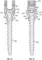
- FIG. 13 is a side view of exemplary bone anchor 400 including fastener 402 having first external thread pitch P1 and sizing component 404 having second external thread pitch P2.
- Sizing component 404 can comprise threaded sleeve 406 having threading 408 extending between first end 410 and second end 412 of threaded sleeve 406.
- Fastener 402 can comprise head 414 and shaft 416.
- Shaft 416 can include threading 418 that extends between a tip (not shown) and head 414.
- Bone anchor 400 can operate similarly to bone anchor 200 of FIG. 7 with the exception that threading 418 can be at a different pitch than threading 220.
- threading 408 can be dual lead and threading 418 can be single lead with double pitch.
- Threading 418 can be configured to have large, deep valleys and can be widely-spaced between threading to provide for deep anchoring in cancellous bone structure.
- Threading 408 can be configured to have small, shallow valleys and can be closely-spaced to provide abundant anchoring in cortical bone.
- pitch P1 can be approximately 3.0 mm and pitch P2 can be approximately 1.5 mm.
- FIG. 14 is a perspective view of a poly-axial bone anchor 500, according to the invention, having threaded sleeve 502 configured to pivotably and rotationally lock housing 504 relative to fastener 506.
- Threaded sleeve 502 can comprise sleeve portion 508 and cup portion 510.
- Housing 504 can comprise a generally U-shaped body having passage 512 into which a stabilization rod can be placed. Passage 512 can be threaded to receive a closure member, such as closure member 11, in order to lock the stabilization rod into housing 504.
- fastener 506 can include spherical or semispherical head 514 that can be positioned within housing 504. Housing 504 can thus be configured to poly-axially pivot with respect to the longitudinal axis of fastener 506. Housing 504 can also rotate three-hundred-sixty degrees about the longitudinal axis of fastener 506.
- sleeve portion 508 can be threaded up the shank of fastener 506 to push cup portion 510 into engagement with housing 504.
- Cup portion 510 can be configured to convert poly-axial bone anchor 500 into a mono-screw bone anchor, e.g., a bone anchor where housing 504 is fixed in a single position relative to fastener 506.
- FIG. 15 is a top view of poly-axial bone anchor 500 of FIG. 14 showing cup portion 510 of threaded sleeve 504 engaging housing 504.
- Cup portion 510 can include high-sides 516 and low-sides 518.
- Housing 504 can include flat, rod passage-sides 520 and rounded, distractor-sides 522.
- Distractor-sides 522 can include sockets 524 which can be configured to receive an instrument, such as a distractor, to manipulate housing 504 and bone anchor 500.
- FIG. 16 is a front view of the poly-axial bone anchor 500 of FIG. 14 showing a high-side 516 of cup portion 510 engaging a rod-passage side 520 of housing 504.
- FIG. 17 is a side view of poly-axial bone anchor 500 of FIG. 14 showing low-side 518 of cup portion 510 engaging distractor-side 522 of housing 504.
- FIG. 18 is a cross-sectional view of poly-axial bone anchor 500 of FIG. 15 taken at section 18-18 showing low-side 518 of cup portion 510 engaging housing 504.
- FIG. 19 is a cross-sectional view of poly-axial bone anchor 500 of FIG. 15 taken at section 19-19 showing high-side 516 of cup portion 510 engaging housing 504.
- housing 504 can also include a lower surface 526 that can be generally flat in a plane perpendicular to the axis of fastener 506.
- Sleeve portion 508 can include internal bore 528 that can be advanced along the shank of fastener 506.
- threading on fastener 506 can be used to forcibly push a flat surface 529 of cup portion 510 against surface 526 to thereby apply an anti-pivoting force against housing 504.
- high-sides 516 and low-sides 518 extend up along rod passage-sides 520 and distractor-sides 522, respectively, of housing 504 to prevent angulation or pivoting of housing 504 relative to fastener 506.
- Engagement of high-sides 516 of cup portion 510 with rod passage-sides 520 of housing 504 and engagement of low-sides 518 of cup portion 510 with distractor-sides 522 can form a multi-faceted engagement, similar to a hex head bolt and wrench configuration, which can also prevent rotation of housing 504 relative to fastener 506 simultaneously with preventing pivoting.
- High-sides 516 and low-sides 518 of cup portion 510 can extend from lower bowl portion 530. As shown in FIGS. 20 - 25 , high-sides 516 and low-sides 518 can be omitted from cup portion 510 so that threaded sleeve 502 can be configured to only prevent angulation or pivoting of housing 504 relative to fastener 506, while permitting rotation of housing 504 relative to fastener 506.
- FIG. 20 is a perspective view of poly-axial bone anchor 500 having threaded sleeve 502B configured to pivotably lock housing 504 relative to fastener 506.
- FIG. 21 is a top view of poly-axial bone anchor 500B of FIG. 20 showing cup portion 510 of threaded sleeve 502B having axi-symmetric bowl portion 530 engaging housing 504.
- FIG. 22 is a front view of poly-axial bone anchor 500 of FIG. 20 showing rim 532 of axi-symmetric bowl portion 530 engaging rod-passage side 520 of housing 504.
- FIG. 23 is a side view of the poly-axial bone anchor of FIG. 20 showing rim 532 of axi-symmetric bowl portion 530 engaging distractor side 522 of housing 504.
- FIG. 24 is a cross-sectional view of poly-axial bone anchor 500 of FIG. 21 taken at section 24-24 showing rim 532 of bowl portion 530 engaging rim surface 526 of housing 504.
- FIG. 25 is a cross-sectional view of poly-axial bone anchor 500 of FIG. 21 taken at section 25-25 showing rim 532 of bowl portion 530 engaging rim surface 526 of housing 504.
- FIGS. 20 - 25 include the same references numbers as FIGS. 14 - 19 with the exception of high-sides 516 and low-sides 518 being replaced with rim 532.
- rim 532 projects axially from bowl portion 530 instead of high-sides 516 and low-sides 518.
- rim 532 extends three-hundred-sixty degrees around bowl portion 530.
- threaded sleeve 502B of FIG. 20 includes flat surface 529 that can be pushed against surface 526 of housing 504 to inhibit pivoting of housing 504 relative to fastener 506.
- rim 532 does not project far enough to engage rod passage-sides 520 and distractor-sides 522, thereby not interfering with the ability of housing 504 to rotate about the longitudinal axis of fastener 506.
- FIG. 26 is a perspective view of poly-axial bone anchor 600 , according to the invention, threaded sleeve 602 configured to uni-planarly lock housing 604 relative to fastener 606.
- Threaded sleeve 602 can comprise sleeve portion 608 and saddle portion 610.
- Housing 604 and fastener 606 can be configured similarly as housing 504 and fastener 506 of FIGS. 14 - 19 . Further discussion is omitted here except to say that with respect to housing 604 and fastener 606, 500 series reference numbers are replaced with 600 series reference numbers.
- FIG. 27 is a top view of poly-axial bone anchor 600 of FIG. 26 showing saddle portion 610 of threaded sleeve 602 engaging housing 604.
- Saddle portion 610 can include high-sides 616 and low-sides 618.
- Housing 604 can include flat, rod passage-sides 620 and rounded, distractor-sides 622.
- Distractor-sides 622 can include sockets 624 which can be configured to receive an instrument, such as a distractor, to manipulate housing 604 and bone anchor 600.
- FIG. 28 is a front view of poly-axial bone anchor 600 of FIG. 26 showing high-side 616 of saddle portion 610 engaging rod-passage side 620 of housing 604.
- FIG. 29 is a side view of poly-axial bone anchor 600 of FIG. 26 showing low-side 618 of saddle portion 610 disengaging distractor-side 622 of housing 604.
- FIG. 30 is a cross-sectional view of poly-axial bone anchor 600 of FIG. 27 taken at section 30-30 showing low-side 618 of saddle portion 610 disengaging housing 604.
- FIG. 31 is a cross-sectional view of poly-axial bone anchor 600 of FIG. 27 taken at section 31-31 showing high-side 616 of saddle portion 610 engaging flat portion of housing 604.
- housing 604 can also include lower surface 626 that can be generally flat in a plane perpendicular to the axis of fastener 606.
- Sleeve portion 608 can include internal bore 628 that can be advanced along the shank of fastener 606. For example, threading on fastener 606 can be used to forcibly push a notched surface 629 of cup portion 610 against surface 626 to thereby apply an anti-rotation force against housing 604.
- high-sides 616 extend up along rod passage-sides 620 of housing 504 to prevent angulation or pivoting of housing 504 relative to fastener 506 in a single bi-axial, or uni-planar, direction (e.g, movement along one axis in two directions), specifically the axial direction extending perpendicular to the planes of flat, rod passage-sides 620.
- High-sides 616 can also prevent rotation of housing 604.
- low-sides 618 do not extend up from bowl portion 630 to prevent angulation or pivoting of housing 604.
- housing 604 is permitted to move in a single bi-axial direction (e.g., along a single axis in two directions) that is parallel to the planes of flat, rod passage-sides 620. Notched surface 629 can be notched to permit this angulation of housing 604.
- only a single high-side 616 can extend from lower bowl portion 630. As shown in FIGS. 32 - 37 , one of high-side 616 can be omitted from cup portion 610 so that threaded sleeve 602 can be configured to only prevent angulation or pivoting of housing 604 relative to fastener 606 in one direction, while permitting angulation or pivoting in three directions.
- FIG. 32 is a perspective view of poly-axial bone anchor 600 having threaded sleeve 602B configured to uni-directionally, or uni-axially (e.g, movement along one axis in one direction), lock housing 604 relative to fastener 606.
- FIG. 33 is a top view of poly-axial bone anchor 600 of FIG. 32 showing saddle portion 610 of threaded sleeve 602B engaging housing 604.
- FIG. 34 is a front view of poly-axial bone anchor 600 of FIG. 32 showing truncated-side 616B of saddle portion 610 disengaging rod-passage side 620 of housing 604.
- FIG. 35 is a side view of poly-axial bone anchor 600 of FIG. 32 showing high-side 616 of saddle portion 610 engaging rod passage side 620 of housing 604.
- FIG. 36 is a cross-sectional view of poly-axial bone anchor 600 of FIG. 33 taken at section 36-36 showing truncated-side 616B of saddle portion 610 disengaging housing 604.
- FIG. 37 is a cross-sectional view of poly-axial bone anchor 600 of FIG. 33 taken at section 37-37 showing single high-side 616 of saddle portion 610 engaging a single, flat, rod passage-side 620 of housing 604.
- FIGS. 32 - 37 include the same references numbers as FIGS. 26 - 31 with the exception of one of high-sides 616 being shortened to form truncated-side 616B.
- truncated-side 616B does not extend from bowl portion 630 far enough to interfere with angulation or pivoting of housing 604.
- threaded sleeve 602B of FIG. 32 includes flat surface 629 that can be pushed against surface 626 of housing 604 to inhibit pivoting and rotation of housing 604 relative to fastener 606.
- rim truncated-side 616B does not project far enough to engage one of rod passage-sides 620, thereby not interfering with the ability of housing 604 to pivot in that direction.
- housing 604 can pivot in three uni-axial directions and is inhibited from pivoting in a fourth uni-axial direction.
- Methods of using the threaded sleeves of FIGS. 14 - 37 can include preoperatively and intraoperatively evaluating a patient such as via reviewing images of the patient or tissue and bone of the patient.
- the evaluation can be used to determine how many fixed bone anchors are desired, how many mono-axial bone anchors are desired, how many uni-axial bone anchors are desired and how many poly-axial bone anchors are desired to implant a particular device or system, such as a spinal stabilization system.
- the threaded sleeves, cups and saddles of the present application can be preoperatively and intraoperatively engaged with shafts of fasteners to provide the desired interaction with a housing.
- the sleeves, cups and saddles can be threaded or slid up a shaft of a fastener until walls of the sleeve, cup or saddle engage walls or surfaces of the housing to provide the desired rotational or directional limiting, or combinations thereof.
- a hospital or other medical facility may only keep fewer types of bone anchors or only one type of bone anchor, e.g., fastener and housing combination, in stock, such as a universal, multi-axis, multi-rotational bone anchor. Smaller, less expensive sleeves and housing limiters can be kept in stock to reduce inventory size and cost.
Landscapes
- Health & Medical Sciences (AREA)
- Orthopedic Medicine & Surgery (AREA)
- Life Sciences & Earth Sciences (AREA)
- Surgery (AREA)
- Neurology (AREA)
- Heart & Thoracic Surgery (AREA)
- Engineering & Computer Science (AREA)
- Biomedical Technology (AREA)
- Nuclear Medicine, Radiotherapy & Molecular Imaging (AREA)
- Medical Informatics (AREA)
- Molecular Biology (AREA)
- Animal Behavior & Ethology (AREA)
- General Health & Medical Sciences (AREA)
- Public Health (AREA)
- Veterinary Medicine (AREA)
- Surgical Instruments (AREA)
Description
- This document pertains generally, but not by way of limitation, to systems and methods for fixation of bones during orthopedic procedures. More particularly, this disclosure relates to, but not by way of limitation, vertebral bone anchors particularly suited for use in weakened or degenerative bone.
- The spinal column of a patient includes a plurality of vertebrae linked to one another by facet joints and an intervertebral disc located between adjacent vertebrae. The facet joints and intervertebral disc allow one vertebra to move relative to an adjacent vertebra, providing the spinal column a range of motion. Diseased, degenerated, damaged, or otherwise impaired facet joints and/or intervertebral discs may cause the patient to experience pain or discomfort and/or loss of motion, thus prompting surgery to alleviate the pain and/or restore motion of the spinal column.
- One possible method of treating these conditions is to immobilize a portion of the spine to allow treatment. Traditionally, immobilization has been accomplished by rigid stabilization. For example, in a conventional spinal fusion procedure, a surgeon restores the alignment of the spine or the disc space between vertebrae by installing a rigid fixation rod between pedicle screws secured to adjacent vertebrae. Bone graft is placed between the vertebrae, and the fixation rod cooperates with the screws to immobilize the two vertebrae relative to each other so that the bone graft may fuse with the vertebrae.
- Dynamic stabilization has also been used in spinal treatment procedures. Dynamic stabilization does not result in complete immobilization, but instead permits a degree of mobility of the spine while also providing sufficient support and stabilization to effect treatment. Dynamic stabilization systems can include a flexible construct extending between pedicle screws installed in adjacent vertebrae of the spine.
- Examples of stabilization systems are the Dynesys® System, the Sequoia® Thoracolumbar Pedicle Screw System and the Lineum® OCT Spine System available from Zimmer Biomet Spine, Inc. of Broomfield, Colorado.
- In addition,
WO 2010/111470 discloses a variable height, multi-axial bone screw assembly;WO 2011/056707 discloses a multiplanar bone anchor system;US 2005/273101 is concerned with a bone screw and osteosythesis device for fixing at least two bone parts relate to one another in a fixation position;GB 2 512 063 WO 2006/104709 discloses stabilizer for a bone anchor includes a tubular body. - The present inventors have recognized, among other things, that a problem to be solved can include the need to provide bone anchors, such as threaded fasteners or screws, in bone that is degenerative or otherwise weakened. If bone anchors are inserted into weakened bone, there can be the potential for the fastener to move position or become dislodged, thereby rendering the anchoring effects provided by the fastener less effective or altogether ineffective.
- The present subject matter can help provide a solution to various problems associated with the anchoring of fasteners in weakened or partially weakened bone by providing a sizing component that can be coupled to the fastener to enlarge the anchoring footprint of the fastener. The sizing component can be modular such that it can be attached to standard fasteners already typically maintained in inventory and/or can be combined with other sizing components to change the capabilities of the sizing component. Additionally, various sizing components can come in different shapes and configurations to accommodate bone that is weakened or degenerative in different capacities, thereby allowing a practitioner or surgeon the ability to choose from a variety of sizing components for use with particular bone defects of a particular patient. In various examples, the sizing component can be a sleeve into which a fastener is threaded to enlarge all or part of the shaft diameter of the fastener to provide radial anchoring in cancellous bone inside the bone, or a cap into which a fastener is threaded to provide axial anchoring into cortical bone at a surface of the bone.
- In an example, the present subject matter can help provide a solution to this problem, such as by providing a bone anchor system that can comprise: a fastener, a rod housing and a first directional component. A bone anchor system according to the invention is defined in claim 1, while preferred embodiments are set forth in the dependent claims.
- The fastener comprises: a shaft having a shaft diameter; an anchoring projection, such as threading, on the shaft; and a head at an end of the shaft. A rod housing is connected to the head of the fastener. A first directional component is configured for connection to the fastener. The first directional component comprises: a first body portion having a first outer diameter larger than the shaft diameter; a first bore extending through the first body portion, the first bore sized to receive the shaft diameter; and a first locking component extending from the first body portion configured to engage one or more exterior surfaces of the rod housing to limit movement of the housing.
- Also described is, a bone anchor directional component can comprise a first body portion, a first bore and a first locking component. The first body portion can have a first outer diameter larger than the shaft diameter. The first bore can extend through the first body portion and can be sized to receive a shaft of a bone anchor. The first locking component can extend from the first body portion and can be configured to engage a rod housing of the bone anchor to limit movement of the housing relative to a fastener shaft.
- This overview is intended to provide an overview of subject matter of the present patent application. It is not intended to provide an exclusive or exhaustive explanation of the invention. The detailed description is included to provide further information about the present patent application.
- The following embodiments disclosed in
figures 1-13 and surgical methods disclosed in the description are not according to the invention and are present for illustration purposes only. -
FIG. 1 is an exploded view of an exemplary bone anchor comprising a fastener, a housing, a rod and a closure member. -
FIG. 2 is a perspective view of the bone anchor ofFIG. 1 showing the rod secured to the housing between the fastener and the closure member. -
FIG. 3 is a perspective view of an exemplary bone anchor having a first embodiment of a sizing component comprising a threaded sleeve disposed along a shaft of a threaded fastener and having radial extending enlarging threading. -
FIG. 4 is a perspective view of an exemplary bone anchor having a second embodiment of a sizing component comprising a cap disposed along a shaft of a threaded fastener and having axially extending fixation teeth. -
FIG. 5 is a perspective view of an exemplary bone anchor having a third embodiment of a sizing component comprising a cap having a threaded sleeve that extends along only a portion of a threaded fastener. -
FIG. 6 is a perspective view of an exemplary bone anchor having a fourth embodiment of a sizing component comprising a cap having a threaded sleeve that extends along all but a tip portion of a threaded fastener. -
FIG. 7 is a side view of another exemplary bone anchor having a sizing component comprising a threaded sleeve. -
FIG. 8 is a cross-sectional view of the bone anchor and sizing component ofFIG. 7 . -
FIG. 9 is a side view of a first sizing component such as the one shown inFIGS. 7 and 8 axially abutted with a second sizing component of similar construction. -
FIG. 10 is a cross-sectional view of the first and second sizing components ofFIG. 9 . -
FIG. 11 is a cross-sectional view of a portion of the bone anchor ofFIG. 8 having a stop and an embodiment of a sizing component having a cap with axial fixation teeth and a sleeve. -
FIG. 12 is a flow chart diagramming a method of implanting a sizing component of the present application. -
FIG. 13 is a side view of another exemplary bone anchor including a fastener having a first external thread pitch and a sizing component having a second external thread pitch. -
FIG. 14 is a perspective view of a poly-axial bone anchor having a threaded sleeve configured to pivotably and rotationally lock a housing relative to a fastener. -
FIG. 15 is a top view of the poly-axial bone anchor ofFIG. 14 showing a cup of the threaded sleeve engaging the housing. -
FIG. 16 is a front view of the poly-axial bone anchor ofFIG. 14 showing a high-side of the cup engaging a rod-passage side of the housing. -
FIG. 17 is a side view of the poly-axial bone anchor ofFIG. 14 showing a low-side of the cup engaging a distractor side of the housing. -
FIG. 18 is a cross-sectional view of the poly-axial bone anchor ofFIG. 15 taken at section 18-18 showing the low-side of the cup engaging a curved portion of the housing. -
FIG. 19 is a cross-sectional view of the poly-axial bone anchor ofFIG. 15 taken at section 19-19 showing the high-side of the cup engaging a flat portion of the housing. -
FIG. 20 is a perspective view of a poly-axial bone anchor having a threaded sleeve configured to pivotably lock a housing relative to a fastener. -
FIG. 21 is a top view of the poly-axial bone anchor ofFIG. 20 showing an axi-symmetric cup of the threaded sleeve engaging the housing. -
FIG. 22 is a front view of the poly-axial bone anchor ofFIG. 20 showing a rim of the axi-symmetric cup engaging a rod-passage side of the housing. -
FIG. 23 is a side view of the poly-axial bone anchor ofFIG. 20 showing the rim of the axi-symmetric cup engaging a distractor side of the housing. -
FIG. 24 is a cross-sectional view of the poly-axial bone anchor ofFIG. 21 taken at section 24-24 showing the rim of the cup engaging a rim surface of the housing. -
FIG. 25 is a cross-sectional view of the poly-axial bone anchor ofFIG. 21 taken at section 25-25 showing the rim of the cup engaging a rim surface of the housing. -
FIG. 26 is a perspective view of a poly-axial bone anchor having a threaded sleeve configured to uni-planarly lock a housing relative to a fastener. -
FIG. 27 is a top view of the poly-axial bone anchor ofFIG. 26 showing a saddle of the threaded sleeve engaging the housing. -
FIG. 28 is a front view of the poly-axial bone anchor ofFIG. 26 showing a high-side of the saddle engaging a rod-passage side of the housing. -
FIG. 29 is a side view of the poly-axial bone anchor ofFIG. 26 showing a low-side of the saddle disengaging a distractor side of the housing. -
FIG. 30 is a cross-sectional view of the poly-axial bone anchor ofFIG. 27 taken at section 30-30 showing the low-side of the saddle disengaging the housing. -
FIG. 31 is a cross-sectional view of the poly-axial bone anchor ofFIG. 27 taken at section 31-31 showing the high-side of the saddle engaging a flat portion of the housing. -
FIG. 32 is a perspective view of a poly-axial bone anchor having a threaded sleeve configured to uni-directionally lock a housing relative to a fastener. -
FIG. 33 is a top view of the poly-axial bone anchor ofFIG. 32 showing a saddle of the threaded sleeve engaging the housing. -
FIG. 34 is a front view of the poly-axial bone anchor ofFIG. 32 showing a low-side of the saddle disengaging a rod-passage side of the housing. -
FIG. 35 is a side view of the poly-axial bone anchor ofFIG. 32 showing a high-side of the saddle engaging a distractor side of the housing. -
FIG. 36 is a cross-sectional view of the poly-axial bone anchor ofFIG. 33 taken at section 36-36 showing the low-side of the saddle disengaging the housing. -
FIG. 37 is a cross-sectional view of the poly-axial bone anchor ofFIG. 33 taken at section 37-37 showing a single high-side of the saddle engaging a single flat portion of the housing. -
FIG. 1 is an exploded view illustrating components ofexemplary bone anchor 10 androd 12.Bone anchor 10 can includeclosure member 11,retainer assembly 13,fastener 20 andhousing 30.Retainer assembly 13 can includeretainer ring 14,wave washer 15 andseat 16.Fastener 20 can includehead 21, keyedportion 22 andshank 23.Housing 30 can includeupper housing 40 andlower housing 50.Upper housing 40 can include opposingarms 41, threading 42 andU-shaped channel 43, which extends along a transverse axis that is transverse to the axial axis offastener shank 23. -
FIG. 2 is a perspective view ofbone anchor 10 ofFIG. 1 showing rod 12 secured tohousing 30 betweenfastener 20 andclosure member 11.FIGS. 1 and 2 are discussed concurrently. -
Bone anchor 10 can be used to couplerod 12 or another elongate member to a boney structure. For example,shank 23 offastener 20 can be inserted into and throughupper housing 40 andlower housing 50 to connect to a pedicle of a vertebra.Retainer assembly 13 can be inserted intochannel 43 to sit belowrod 12.Retainer ring 14 can be connected toupper housing 40 to lockwave washer 15 andseat 16 inhousing 30 below threading 42, thereby at least partially immobilizingfastener 20 withinhousing 30.Rod 12 can fit intoU-shaped channel 43 formed by opposingarms 41, such as by being inserted intochannel 43 from the top or proximal end ofhousing 30.Closure member 11, which can comprise a set screw or the like, can be threaded into threading 42 to pushrod 12 down intochannel 43 atopretainer assembly 13, thereby at least partially immobilizingrod 12 withinbone anchor 10. -
Bone anchor 10 can include particular degrees of adjustability that can help ensure thatfastener 20 andelongate member 12 can be locked down at the particular locations and orientations desired by the practitioner or surgeon. For example,head 21 can be spherical in shape to allow rotation withinhousing 30. In particular,bone anchor 10 can allow for angular deviation ofbone screw 20 away from the axial orientation shown inFIG. 1 . Such an angular deviation may be referred to as "angulation", and desired angulations may exceed 35 degrees, 40 degrees, 45 degrees, or more, in some instances. Further description of such angulation is described inU.S. Pat. No. 9,289,244 to Hestad et al. -
Bone anchor 10 can be delivered or provided to or obtained by a practitioner in a semi-assembled state. In the exemplary design ofFIG. 1 ,housing 30 can be modular, thus formed of multiple components coupled together. For example,housing 30 can include two components that are longitudinally adjacent to each other, namelyupper housing 40 andlower housing 50. Thus,upper housing 40 andlower housing 50 can be pre-assembled. Also,fastener 20 can be pre-inserted intohousing 30.Housing 30 can have a bore that extends longitudinally through theupper housing 40 andlower housing 50, generally coaxial with the longitudinal axis ofbone anchor 10. Upper housing can include bore 46 andlower housing 50 can include bore 52 which can each be aligned and centered along the central axial axis offastener 20 whenfastener 20 is assembled withhousing 30. -
Fastener 20 can have threadedshank 23 that extends out from the bottom oflower housing 50 atbore 52 after passing throughbore 46.Head 21 can be sized such thathead 21 can pass intobore 46, but cannot pass throughbore 52.Head 21 offastener 20 can be generally spherical in shape, so that it may pivot with respect tohousing 30 onlower housing 50. - Prior to final assembly,
shank 23 can be dropped downward or otherwise inserted into the top ofhousing 30 throughupper housing 40 andlower housing 50 so thathead 21 can rest onlower housing 50. Alternatively,fastener 20 can be bottom-loaded intoupper housing 40, and thenlower housing 50 can be positioned aroundshank 23 and coupled ontoupper housing 40, so thathead 21 can be held in place withinupper housing 40 atoplower housing 50. -
Head 21 offastener 20 can be held in place byretainer assembly 13, which can preventfastener 20 from being pulled upward out of or otherwise displaced fromhousing 30.Retainer assembly 13 can allow pivoting ofscrew head 21 with respect tohousing 30.Retainer assembly 13 can be typically in the form of one or more rings having a central aperture, which can allow the practitioner to insert a screwdriver through the apertures of the rings to engage a driver interface such as akeyed portion 22 onhead 21 offastener 20. Theexemplary retainer assembly 13 inFIG. 1 can includeseat 16 that can contacthead 21, biasing member orwave washer 15, andretainer ring 14 farthest away fromscrew head 21.Seat 16 can include a concave annular region that has a radius of curvature matched to that ofscrew head 21, which facilitates pivoting ofhead 21. The concave annular region can also increase the frictional contact withhead 21, which facilitatesfastener 20 being held in place byseat 16 in the desired angular orientation. - Biasing
member 15 can be inserted intochannel 43 so as to be disposed on top ofseat 16.Retainer ring 14 can be coupled tohousing 30, such as via split-ring configuration, to secure biasingmember 15 betweenseat 16 andretainer ring 14. In an example, biasingmember 15 andretainer ring 14 can fit around an annular portion ofseat 16. Next,rod 12 can be positioned on top ofretainer ring 14. - To lock the components of
bone anchor 10 in place, the practitioner can screwclosure member 11 intothreads 42 at the upper portion ofhousing 30 untilclosure member 11 engagesrod 12.Closure member 11 can forcerod 12 against the upper surface ofseat 16, pushingretainer ring 14 and biasingmember 15 down aroundseat 16, and in turn can forceseat 16 againsthead 21 of thescrew 20. Prior to final tightening ofclosure member 11, biasingmember 15 can causeseat 16 to frictionally engagehead 21 to resist movement ofhousing 30 with respect tofastener 20, which can allow for repositioning ofshank 23. After complete tightening ofclosure member 11, the frictional force betweenseat 16 ofretainer assembly 13 andhead 21 can be sufficient to lockfastener 20 in place with respect tohousing 30. In an example,U-shaped channel 43 can be deep enough so thatclosure member 11 does not forcerod 12 against the bottom ofU-shaped channel 43, withrod 12 being immobilized betweenseat 16 andclosure member 11. In an example,retainer assembly 13 can be omitted, andclosure member 11 can forcerod 12 directly againsthead 21 offastener 20 to securefastener 20 in place. In an example,closure member 11 can push rod against portions ofarms 41 forming the bottom ofchannel 43 to immobilizerod 12, with or withoutretainer assembly 14. In such an example withretainer assembly 14, angulation offastener 20 can be partially immobilized by biasingmember 15, and in such an example withoutretainer assembly 14fastener 20 can be freely angulated (e.g. is not immobilized). - In practice,
fastener 20 is threaded into bone that is structurally sound such thatbone anchor 10 is substantially immobilized via engagement of threading onshank 23 extending radially fromshank 23 into cancellous bone. However, sometimes bone at a location where it is desirable to provide anchoring bybone anchor 10 is inadequate for immobilizing a fastener. Such inadequate bone can arise from a variety of conditions, such as osteoporosis or other degenerative conditions that cause the bone structure to become compromised and weakened. Sometimes it is impractical to movebone anchor 10 to another location for a variety of reasons, such as there being no other available bone structure to provide anchoring or because a bore has already been drilled into the bone and it would unnecessarily further weaken the bone to drill another hole. The present disclosure addresses these issues in anchoring fasteners in boney structure by providing a sizing component that can be coupled to the fastener to increase the anchoring capacity or footprint of the fastener to reach a larger area and thereby reach healthy or otherwise structurally sound bone for anchoring. -
FIG. 3 is a perspective view ofexemplary bone anchor 60 havingsizing component 62, which can comprise threadedsleeve 64, enlarging threading 66,first end 68,second end 70 andcentral bore 72.Bone anchor 60 can comprisefastener 74 andhousing 76.Fastener 74 can includeshaft 78, which can include anchor threading 80. -
Bone anchor 60 can function similarly to that ofbone anchor 10 ofFIG. 1 . For example,fastener 74 can includespherical head 82 that can rotate withinhousing 76, which can includeslot 84 for receiving a rod. Sizingcomponent 62 can be sized to mate withshaft 78 offastener 74. For example, the outer diameter ofshaft 78 can be sized to fit within the diameter ofcentral bore 72, and internal female threading ("sizing threading") withincentral bore 72 can be sized to mate with male anchor threading 80. Sizingcomponent 62, however, can be configured to operate with other bone anchor devices, such asbone anchor 200 ofFIGS. 7-9 . -
Sleeve 64 can extend along a central axis that is configured to be co-axial with the central axis ofshaft 78.Sleeve 64 can be tapered betweenfirst end 68 andsecond end 70 in order to provide a smooth transition between the outer diameter ofshaft 78 and the outer diameter ofsleeve 64. First end 68 ofsleeve 64 can have a diameter of the desired outer diameter of sizingcomponent 62. The diameter offirst end 68 can be selected to increase the diameter ofshaft 78 by any desirable amount to provide a larger anchoring footprint, as discussed below.Second end 70 can have a diameter that is just slightly larger than the outer diameter ofshaft 78 sufficient to allow insertion ofshaft 78 intosleeve 64. Thus, the diameter ofsleeve 64 can increase fromsecond end 70 tofirst end 68 so that, asshaft 78 is threaded into bone, sizingcomponent 62 can be eased or gradually inserted into the bore in the bone. However, the diameter ofsleeve 64 need not increase in a steady manner such that the widest portion ofsleeve 64 need not be located atfirst end 68. Enlarging threading 66 onsleeve 64 can be sized to be the same as anchor threading 80 onshaft 78. For example, threading 66 onsleeve 64 can have the same pitch as threading 80 onshaft 78 to facilitate smooth entry offastener 74 into a bone bore, particularly one that is pre-tapped with threading. In other words, anchor threading 80 and enlarging threading 66 can have the same pitch, but with different diameters, to ensurefastener 74 and sizingcomponent 62 advance into the bone at the same rate and prevent binding. As such, threading 66 can comprise a continuation of threading 80 that in aggregate extends fromtip 86, alongshaft 78, ontosecond end 70, increasing in size alongsleeve 64 and tofirst end 68. In other examples, threading 66 can be dual lead and threading 80 can be single lead with double pitch and have larger valleys to provide deep anchoring in the bone structure, as is discussed in greater detail with reference toFIG. 13 . - Sizing
component 62 can comprisessleeve 64 that can enlarge the diameter ofshaft 78. Thus, assleeve 64 is threaded ontoshaft 78, the outer diameter ofsleeve 64 and threading 66 can radially increase the diameter ofbone anchor 60 to allowshaft 78 to increase or enlarge the anchoring footprint offastener 74. In particular,shaft 78 can be configured to anchorbone anchor 60 into a bone bore having approximately the same diameter asshaft 78. However, as discussed, the boney structure may be weakened or deficient such thatthreads 80 cannot take adequate hold in the boney structure, thereby leaving open the possibility ofbone anchor 60 becoming dislodged or displaced.Sleeve 64 can enlargeshaft 78 such thatbone anchor 60 can become engaged in bone outside of, or larger than, the diameter ofshaft 78. For example,sleeve 64 can be selected to have an outer diameter that is larger than a diseased or weakened bone area surrounding a bone bore into whichshaft 78 is threaded. Thus, threading 66 ofsleeve 64 can provide anchoring in healthy or structurally sound bone material. -
Sleeve 64 can be threaded ontoshaft 78 up to the proximal end of threading 80 nearspherical head 82. As such,sleeve 64 can be configured to overcome deficient boney structure proximate a cortical bone surface surrounding the bone bore. Additionally,sleeve 64 can provide strengthening ofshaft 78 nearspherical head 82 in a location that can sometimes be subjected to stress during installation and use. The axial length ofsleeve 64 allows sizingcomponent 62 to engage healthy cancellous bone, displacing any weak or unhealthy cancellous bone. As discussed below,shaft 78 can be provided with a stop or locking feature (e.g. stop 248 ofFIG. 11 ) to preventsleeve 64 from backing out of the bone bore and protruding beyond the cortical bone. - The diameter of
sleeve 64 can vary in different embodiments of sizingcomponent 62. Likewise, the length of sizingcomponent 62 betweenfirst end 68 and second end 79 can vary in different embodiments of sizingcomponent 62. Thus, a variety of sizingcomponents 62 can be provided in inventory, such as in a system, set, kit or package, or as part of a surgical system, to allow a surgeon or practitioner to intra-operatively select one or more sizing components of desired length and diameter, or material to compensate for or overcome weakened or defective boney structure at a particular surgical site of a patient at a location where the procedure is performed. -
FIG. 4 is a perspective view ofexemplary bone anchor 60 havingsizing component 90, which can comprisecap 92 havingaxial fixation teeth 94 andcentral bore 96.Bone anchor 60 can be configured in the same manner as described with reference toFIG. 3 and can function similarly asbone anchor 10 ofFIGS. 1 and 2 .Bone anchor 60 can comprisefastener 74 andhousing 76, which includesslot 84.Fastener 74 can includeshaft 78, which can include threading 80,head 82 andtip 86. - Sizing
component 90 can be sized to mate withshaft 78 offastener 74. For example, the outer diameter ofshaft 78 can be sized to fit within the diameter ofcentral bore 96, and internal threading withincentral bore 96 can be sized to mate with threading 80. Sizingcomponent 90, however, can be configured to operate with other bone anchor devices, such asbone anchor 200 ofFIGS. 7-9 . -
Cap 92 can extend along a central axis that is configured to be co-axial with the central axis ofshaft 78.Cap 92 can have an octagonal or hexagonal outer perimeter surface shape in order to engage a driver device. As such, insertion and removal of sizingcomponent 90 can be facilitated with an instrument such as an open end wrench. However, the shape of the outer perimeter ofcap 92 can have other configurations, such as square or circular. -
Cap 92 can have an outer perimeter size selected to increase the diameter or size ofshaft 78 any desirable amount to provide a larger anchoring footprint, as discussed below. In particular,fixation teeth 94 can extend fromrim 98 to engage corticalbone surrounding shaft 78.Rim 98 can comprise a flange that can extend radially and/or axially fromcap 92 to positionfixation teeth 94 for engaging bone.Fixation teeth 94 can extend axially fromrim 98 in a distal direction away fromcap 92.Fixation teeth 94 can have a circumferential orientation to facilitate insertion into the cortical bone as sizingcomponent 90 is rotated. In an example,fixation teeth 94 can be oriented in a clockwise circumferential direction when viewed from the proximal end ofshaft 78 near spherical head 84 (as depicted inFIG. 4 ) to facilitate insertion offixation teeth 94 whencap 92 is rotated in a clockwise or right-hand thread direction. In other examples,fixation teeth 94 can have different shapes or can be replaced with textured or jagged surfaces alongrim 98 for engaging bone. - As
cap 92 is threaded ontoshaft 78, the outer size ofcap 92 can radially increase the diameter ofbone anchor 60 to allowshaft 78 to increase or enlarge the anchoring footprint offastener 74. In particular,shaft 78 can be configured to anchorbone anchor 60 into a bone bore having approximately the same diameter asshaft 78. However, as discussed, the boney structure may be weakened or deficient such thatthreads 80 cannot take adequate hold in the boney structure, thereby leaving open the possibility ofbone anchor 60 becoming dislodged or displaced.Cap 92 can enlargeshaft 78 such thatbone anchor 60 can become engaged in bone outside of, or larger than, the diameter ofshaft 78. For example, cap 92 can be selected to have an outer size that is larger than a diseased or weakened bone area surrounding a bone bore into whichshaft 78 is threaded. Thus,fixation teeth 94 ofcap 92 can provide anchoring in healthy or structurally sound bone material that surrounds the bone bore. -
Cap 92 can be threaded ontoshaft 78 up to the proximal end of threading 80 nearspherical head 82. As such,cap 92 can be configured to overcome deficient boney structure proximate a cortical bone surface surrounding the bone bore.Shaft 78 continues to provide anchoring within the bone bore in cancellous bone. As discussed below,shaft 78 can be provided with a stop feature (e.g. stop 248 ofFIG. 11 ) to preventcap 92 from backing out from engagement with the cortical bone. - The diameter of
cap 92 can vary in different embodiments of sizingcomponent 90. Likewise, the shape, such as the length, offixation teeth 94 can vary in different embodiments of sizingcomponent 90. Thus, a variety of sizingcomponents 90 can be provided in inventory, such as in a system, set, kit or package, or as part of a surgical system, to allow a surgeon or practitioner to intra-operatively select one or more sizing components of desired length and diameter to compensate for or overcome weakened or defective boney structure at a particular surgical site of a patient at a location where the procedure is performed. -
FIG. 5 is a perspective view ofexemplary bone anchor 60 having sizing component 100, which can be configured similarly as sizingcomponent 90 ofFIG. 4 with the addition ofextension sleeve 102. Sizing component 100 can also includecap 92,axial fixation teeth 94,central bore 96 andrim 98.Extension sleeve 102 can include threading 104.Bone anchor 60 can be configured in the same manner as described with reference toFIG. 3 and can function similarly asbone anchor 10 ofFIGS. 1 and 2 .Bone anchor 60 can comprisefastener 74 andhousing 76, which includesslot 84.Fastener 74 can includeshaft 78, which can include threading 80,head 82 andtip 86. -
Cap 92 can function similarly as described with reference toFIG. 4 .Extension sleeve 102 and threading 104 can function similarly as threadedsleeve 64 and threading 66 of sizingcomponent 62 ofFIG. 3 . As such,FIG. 5 depicts a combination of the embodiments ofFIGS. 3 and 4 whereinfirst end 68 of threadedsleeve 64 extends fromcap 92. -
Extension sleeve 102 can extend fromcap 92 along a central axis that is configured to be co-axial with the central axis ofshaft 78.Extension sleeve 102 can be tapered betweencap 92 anddistal end 106 in order to provide a smooth transition between the outer diameter ofshaft 78 and the outer diameter ofsleeve extension 102. The diameter ofextension sleeve 102 can be selected to increase the diameter ofshaft 78 any desirable amount to provide a larger anchoring footprint, as discussed herein.Distal end 106 can have a diameter that is just slightly larger than the outer diameter ofshaft 78 sufficient to allow insertion ofshaft 78 intoextension sleeve 102. Thus, the diameter ofextension sleeve 102 can be tapered so that, asshaft 78 is threaded into bone, sizing component 100 can be eased or gradually inserted into the bore in the boney structure.Threading 104 onextension sleeve 102 can be sized to be the same as threading 80 onshaft 78. For example, threading 104 onextension sleeve 102 can have the same pitch as threading 80 onshaft 78 to facilitate advancement into the boney structure at the same rate and prevent binding. - Sizing component 100 can comprises
extension sleeve 102 that can be larger than the diameter ofshaft 78, and cap 92 that can be larger than the diameter ofextension sleeve 102. Thus, as sizing component 100 is threaded ontoshaft 78, the outer diameter ofextension sleeve 102 and threading 104 can effectively radially increase the diameter ofshaft 78 to increase or enlarge the anchoring footprint offastener 74, whilecap 92 can further increase the size of the anchoring footprint. In particular,extension sleeve 102 can increase the anchoring footprint in the radial and axial directions to engage cancellous bone in a bone bore, whilecap 92 andfixation teeth 94 can increase the anchoring footprint in the radial and axial directions to engage cortical bone. Thus,extension sleeve 102 can displace weak or unhealthy cancellous bone to engage healthy cancellous bone, whilefixation teeth 94 can be extended radially beyond weak or unhealthy cortical bone to axially engage healthy cortical bone. - As discussed, the radial diameter of
cap 92 and the axial length ofteeth 94 can vary in different embodiments, and the radial diameter and axial length ofextension sleeve 102 can vary in different embodiments such that different sizing components 100 can be used as components in different systems, sets, kits or packages. In the depicted example ofFIG. 5 ,extension sleeve 102 has a length sized to only engage cancellous bone near the cortical surface of a bone bore. However, as shown inFIG. 6 ,extension sleeve 102 can be sized to extend along substantially all ofshaft 78. -
FIG. 6 is a perspective view ofexemplary bone anchor 60 havingsizing component 110, which can be configured similarly as sizing component 100 ofFIG. 4 with the addition ofextension sleeve 102 having a greater length. Sizingcomponent 110 can also includecap 92,axial fixation teeth 94,central bore 96 andrim 98.Extension sleeve 102 can include threading 104.Bone anchor 60 can be configured in the same manner as described with reference toFIG. 3 and can function similarly asbone anchor 10 ofFIGS. 1 and 2 .Bone anchor 60 can comprisefastener 74 andhousing 76, which includesslot 84.Fastener 74 can includeshaft 78, which can include threading 80,head 82 andtip 86. - As mentioned, sizing
component 110 can be configured to operate in the same or a similar fashion as sizing component 100 ofFIG. 5 exceptextension sleeve 102 is longer to engage a greater quantity of cancellous bone. Thus,distal end 106 can be positioned further down into a bone bore and the length ofextension sleeve 102 can be used to displace a greater length of cancellous bone to allow threading 104 to engage a greater quantity of healthy cancellous bone.Sleeve 102 can extend across substantially all ofshaft 78 except for the distal tapered end portion wheretip 86 is located. -
FIG. 7 is a side view ofexemplary bone anchor 200 havingsizing component 202 comprising threadedsleeve 204.FIG. 8 is a cross-sectional view ofbone anchor 200 and sizingcomponent 202 ofFIG. 7. FIGS. 7 and 8 are discussed concurrently. Threadedsleeve 204 can also comprise male anchor threading 206,first end 208,second end 210 andcentral bore 212 with female sizing threading 213.Bone anchor 200 can comprisefastener 214, which can includehead 216,shaft 218, threading 220 andsocket 222. -
Bone anchor 200 can function similarly asbone anchor 10 ofFIG. 1 andbone anchor 60 ofFIG. 3 , exceptbone anchor 200 includeshead 216 instead ofspherical head 82. As such,bone anchor 200 is not configured for use with housing 76 (FIG. 3 ). Instead,head 216 can be used with other components, such as plates, fusion systems, intra vertebral spacers and the like.Head 216 can be cylindrical for receding into another component.Head 216 can includesocket 22 for receiving a drive tool, such as a screw driver or hex head wrench. In any event,fastener 214 can be used to securebone anchor 200 to a boney structure. - Sizing
component 202 can function similarly as sizingcomponent 60 ofFIG. 3 . For example, sizingcomponent 202 can havefirst end 208 andsecond end 210, with threadedsleeve 204 being tapered there-between to facilitate smooth insertion into bone. Threading 206 can be sized to match threading 220 ofshaft 218 offastener 214. In other words, threading 206 and threading 220 can have the same pitch to ensurefastener 214 and sizingcomponent 202 advance into the boney structure at the same rate and prevent binding.Sleeve 204 can extend along a central axis that is configured to be co-axial with the central axis ofshaft 218. -
Sleeve 204 of sizingcomponent 202 can enlarge the diameter ofshaft 218 to radially increase the diameter ofbone anchor 200 to allowshaft 218 to increase or enlarge the anchoring footprint offastener 214. In particular,shaft 218 can be configured to anchorbone anchor 200 into a bone bore having approximately the same diameter asshaft 218. However, as discussed, the boney structure may be weakened or deficient such thatthreads 220 cannot take adequate hold in the boney structure, thereby leaving open the possibility ofbone anchor 200 becoming dislodged or displaced.Sleeve 204 can enlargeshaft 218 such thatbone anchor 200 can become engaged in bone outside of, or larger than, the diameter ofshaft 218. For example,sleeve 204 can be selected to have an outer diameter that is larger than a diseased or weakened bone area surrounding a bone bore into whichshaft 218 is threaded. Thus, threading 206 ofsleeve 204 can provide anchoring in healthy or structurally sound bone material. -
Sleeve 204 can be threaded ontoshaft 218 up to the proximal end of threading 220 nearhead 216. As such,sleeve 204 can be configured to overcome deficient boney structure proximate a cortical bone surface surrounding the bone bore, and can be used to strengthenshaft 218. The axial length ofsleeve 204 allows sizingcomponent 202 to engage healthy cancellous bone, displacing any weak or unhealthy cancellous bone. - As with other examples and embodiments described herein, the sizes, e.g. length and diameter, of
sleeve 204 can vary in different embodiments of sizingcomponent 202 to permit a variety of sizingcomponents 202 to be provided in inventory, such as in a system, set, kit or package, or as part of a surgical system, to allow a surgeon or practitioner to intra-operatively select one or more sizing components of desired length and diameter to compensate for or overcome weakened or defective boney structure at a particular surgical site of a patient at a location where the procedure is performed. However,first end 208 can include countersink orsocket 224, which can allow for multiple sizingcomponents 202 to be used in conjunction with each other to increase the axial anchoring footprint of sizingcomponent 202, as shown inFIGS. 9 and10 . In other examples,socket 224 can be omitted from sizingcomponent 202 to, for example, provide additional contact with the threaded fastener. -
FIG. 9 is a side view offirst sizing component 202A, such as sizingcomponent 200 shown inFIGS. 7 and 8 , axially abutted withsecond sizing component 202B of similar construction.FIG. 10 is a cross-sectional view of first andsecond sizing components FIG. 9. FIGS. 9 and10 are discussed concurrently. - Sizing
component 202A can include threadedsleeve 204A having threading 206A,first end 208A,second end 210A,central bore 212A, sizingthreading 213A andsocket 224A. Sizingcomponent 202B can include threadedsleeve 204B having threading 206B,first end 208B,second end 210B,central bore 212B, sizingthreading 213B andsocket 224B. - As mentioned, second ends 210A and 210B can be tapered to provide smooth transitions with
shaft 218 offastener 214.Sockets sockets socket 224B can receive all or nearly all of the tapering ofsecond end 210A such that there is no change in the diameter of the joined sizingcomponents sleeves junction 226.Sockets socket 224B of sizingcomponent 202B can include threading 228B to receive threading 206A of sizingcomponent 202A. Thus, multiple sizingcomponents 202 can be axially stacked together to increase the effective length of the sizing component. This can reduce the number and variety of different sizing components needed in inventory to form different systems, sets, kits and packages as described herein. -
FIG. 11 is a cross-sectional view of a portion offastener 214 ofFIG. 8 havingstop 248 and anexemplary sizing component 250 havingcap 252 withaxial fixation teeth 254 andsleeve 256. Sizingcomponent 250 can also includecentral bore 258 andrim 260. Sizingcomponent 250 is similar to sizing component 100 ofFIG. 5 , except being particularly sized for use withfastener 214. As such,central bore 258 can be sized to receive the diameter ofshaft 218 offastener 214, andcentral bore 258 can include female sizing threading 262 to receive male anchor threading 220 ofshaft 218. However, as discussed, any of the sizing components described herein can have different dimensions in different embodiments for use with a variety of different fasteners and bone anchors. -
Cap 252 can be shaped to have surfaces to engage a drive tool, such as a wrench or the like.Rim 260 can extend fromcap 252 to positionteeth 254 radially outward ofsleeve 256.Rim 260 can extend radially outward fromcap 252 and axially away fromcap 252.Teeth 254 can extend axially fromrim 260 to provide axial anchoring in bone surroundingfastener shaft 218.Sleeve 256 can extend axially fromcap 252 withinteeth 254.Sleeve 256 increases the diameter ofshaft 218 such that threading 266 ofsleeve 256 can increase the anchoring footprint offastener 214 beyond what is provided by threading 220.Sleeve 256 and threading 266 can be shaped to smoothly mate withshaft 218 and threading 220. For example,sleeve 256 can be tapered to allow for a smooth entry ofshaft 218 and sizingcomponent 250 into a bone bore. Also, threading 266 can have the same pitch as threading 220 to allow for entry ofshaft 218 and sizingcomponent 250 into a bone bore without binding. - The various embodiments and examples of sizing components described herein can be made of a variety of different materials in different embodiments. In an example, the sizing components can be made of porous metal or biocompatible metal or alloys. In particular examples, the sizing components can be made from titanium or Trabecular Metal™, which is commercially available from Zimmer Inc. In other examples, the sizing components can be made of a polymer, such as polyether ether ketone (PEEK). In yet other examples, the sizing components can be made of autograft or allograft bone.
-
FIG. 12 is a flowchart diagramming method 300 of implanting a sizing component of the present application.Method 300 can include the steps of forming a bone bore in aboney structure 302, tapping the bone bore 304, trialing the bone bore 306, selecting a sizing component for use in the bone bore 308, assembling the sizing component with afastener 310, inserting the fastener into the bone bore 312, engaging one or more portions of the sizing component with theboney structure 314 and increasing the anchoring footprint of the fastener with thesizing component 316. - Forming a bone bore at
step 302 can comprise producing a bore or hole within a boney structure for receiving a bone anchor. A drill or an awl can be used to produce a channel through cortical bone and into cancellous bone. The bone bore can have a diameter that substantially matches the diameter of a fastener, such as a threaded fastener. As such, the diameter of the bone bore can be sized to accommodate threading of a fastener shaft. - Tapping the bone bore at
step 304 can comprise using a thread tap to produce threading in the bone bore to match the threading of a desired threaded fastener of a bone anchor to be used in the bone bore. Any conventional thread tap can be used. In other examples, the bone bore may not be pre-threaded. As such, self-tapping bone fasteners can be used. - Trialing the bone bore at
step 306 can comprise assessing the quality of bone at and around the bone bore via a variety of means. For example, the bone bore can be visually inspected by the surgeon or practitioner to assess the extent of damaged or unhealthy bone in and around the bone bore. Additionally, various instruments can be inserted into the bone bore to determine the extent of unhealthy or damaged bone. For example, a probe can be inserted into the bone bore to allow the surgeon or practitioner to feel the depth of any bone damage. Additionally, a bone anchor may be inserted into the bone bore to evaluate the effectiveness of a fastener used with the bone anchor. For example, a threaded fastener can be inserted or screwed into the bone bore and the surgeon or practitioner can tactilely feel if the fastener provides adequate anchoring support. - Selecting a sizing component at
step 308 can comprise using information determined during trialing of the bone bore atstep 306 to select one or more of the various sizing components described herein. For example, the radius of any damaged or unhealthy bone surrounding the bone bore can be used to select a sizing component of adequate diameter, and the depth of any damaged or unhealthy bone into the bone bore can be used to select a sizing component of adequate length. - Assembling the sizing component with the fastener at
step 310 can comprise connecting the selected sizing component to the selected bone anchor. For example, a fastener of the selected bone anchor can be inserted or threaded into a sleeve or cap of a selected sizing component. In other examples, the sizing component can be connected to the fastener by other mechanisms. In yet other examples, the sizing component can be inserted into the bone first and the fastener can be passed through the sizing component second. - Inserting the fastener into the bone bore at
step 312 can comprise threading the shaft of the fastener of the bone anchor into the bone bore. The shaft can be partially inserted into the bone bore before any sizing component engages boney structure of the bone bore. Alternatively, the sizing component can be initially threaded into the bone bore such that the fastener does not actually contact the bone bore. - The fastener can be advanced such that the sizing component engages the bone structure at
step 314. The sizing component can engage the boney structure in a variety of different ways. In an example, the sizing component can be used to displace cancellous bone within the bone bore atstep 314A, which can be accomplished by engaging enlarging threading of the sizing component, such as that disposed on a sleeve surrounding the shaft of the threaded fastener, with cancellous bone in the bone bore atstep 315A. In an example, the sizing component can be used to engage cortical bone surrounding the bone bore atstep 314B, which can be accomplished by engaging axially extending teeth of the sizing component, such as teeth that extend from a rim surrounding a cap surrounding the shaft of the threaded fastener, to engage cortical bone surrounding the bone bore atstep 315B. Additionally, sizing components can be configured to engage both cortical and cancellous bone such thatsteps step 314, the anchoring footprint of the bone anchor can be increased with the sizing component(s) atstep 316. As such, the bone anchor can be more securely held in place in the bone bore with a reduced risk of becoming displaced. -
FIG. 13 is a side view ofexemplary bone anchor 400 includingfastener 402 having first external thread pitch P1 and sizingcomponent 404 having second external thread pitch P2. Sizingcomponent 404 can comprise threadedsleeve 406 having threading 408 extending betweenfirst end 410 andsecond end 412 of threadedsleeve 406.Fastener 402 can comprisehead 414 andshaft 416.Shaft 416 can include threading 418 that extends between a tip (not shown) andhead 414. -
Bone anchor 400 can operate similarly tobone anchor 200 ofFIG. 7 with the exception that threading 418 can be at a different pitch than threading 220. In particular, threading 408 can be dual lead and threading 418 can be single lead with double pitch. Threading 418 can be configured to have large, deep valleys and can be widely-spaced between threading to provide for deep anchoring in cancellous bone structure. Threading 408 can be configured to have small, shallow valleys and can be closely-spaced to provide abundant anchoring in cortical bone. In one example, pitch P1 can be approximately 3.0 mm and pitch P2 can be approximately 1.5 mm. -
FIG. 14 is a perspective view of a poly-axial bone anchor 500, according to the invention, having threadedsleeve 502 configured to pivotably androtationally lock housing 504 relative tofastener 506. Threadedsleeve 502 can comprisesleeve portion 508 andcup portion 510. - Housing 504 can comprise a generally U-shaped
body having passage 512 into which a stabilization rod can be placed.Passage 512 can be threaded to receive a closure member, such asclosure member 11, in order to lock the stabilization rod intohousing 504. As shown inFIG. 15 ,fastener 506 can include spherical orsemispherical head 514 that can be positioned withinhousing 504. Housing 504 can thus be configured to poly-axially pivot with respect to the longitudinal axis offastener 506. Housing 504 can also rotate three-hundred-sixty degrees about the longitudinal axis offastener 506. As discussed in greater detail below,sleeve portion 508 can be threaded up the shank offastener 506 to pushcup portion 510 into engagement withhousing 504.Cup portion 510 can be configured to convert poly-axial bone anchor 500 into a mono-screw bone anchor, e.g., a bone anchor wherehousing 504 is fixed in a single position relative tofastener 506. -
FIG. 15 is a top view of poly-axial bone anchor 500 ofFIG. 14 showing cup portion 510 of threadedsleeve 504engaging housing 504.Cup portion 510 can include high-sides 516 and low-sides 518. Housing 504 can include flat, rod passage-sides 520 and rounded, distractor-sides 522. Distractor-sides 522 can includesockets 524 which can be configured to receive an instrument, such as a distractor, to manipulatehousing 504 andbone anchor 500. -
FIG. 16 is a front view of the poly-axial bone anchor 500 ofFIG. 14 showing a high-side 516 ofcup portion 510 engaging a rod-passage side 520 ofhousing 504.FIG. 17 is a side view of poly-axial bone anchor 500 ofFIG. 14 showing low-side 518 ofcup portion 510 engaging distractor-side 522 ofhousing 504. -
FIG. 18 is a cross-sectional view of poly-axial bone anchor 500 ofFIG. 15 taken at section 18-18 showing low-side 518 ofcup portion 510engaging housing 504.FIG. 19 is a cross-sectional view of poly-axial bone anchor 500 ofFIG. 15 taken at section 19-19 showing high-side 516 ofcup portion 510engaging housing 504. - As shown in
FIGS. 18 and 19 ,housing 504 can also include alower surface 526 that can be generally flat in a plane perpendicular to the axis offastener 506.Sleeve portion 508 can includeinternal bore 528 that can be advanced along the shank offastener 506. For example, threading onfastener 506 can be used to forcibly push aflat surface 529 ofcup portion 510 againstsurface 526 to thereby apply an anti-pivoting force againsthousing 504. Additionally, high-sides 516 and low-sides 518 extend up along rod passage-sides 520 and distractor-sides 522, respectively, ofhousing 504 to prevent angulation or pivoting ofhousing 504 relative tofastener 506. Engagement of high-sides 516 ofcup portion 510 with rod passage-sides 520 ofhousing 504 and engagement of low-sides 518 ofcup portion 510 with distractor-sides 522 can form a multi-faceted engagement, similar to a hex head bolt and wrench configuration, which can also prevent rotation ofhousing 504 relative tofastener 506 simultaneously with preventing pivoting. - High-
sides 516 and low-sides 518 ofcup portion 510 can extend fromlower bowl portion 530. As shown inFIGS. 20 - 25 , high-sides 516 and low-sides 518 can be omitted fromcup portion 510 so that threadedsleeve 502 can be configured to only prevent angulation or pivoting ofhousing 504 relative tofastener 506, while permitting rotation ofhousing 504 relative tofastener 506. -
FIG. 20 is a perspective view of poly-axial bone anchor 500 having threadedsleeve 502B configured to pivotablylock housing 504 relative tofastener 506.FIG. 21 is a top view of poly-axial bone anchor 500B ofFIG. 20 showing cup portion 510 of threadedsleeve 502B having axi-symmetric bowl portion 530engaging housing 504. -
FIG. 22 is a front view of poly-axial bone anchor 500 ofFIG. 20 showing rim 532 of axi-symmetric bowl portion 530 engaging rod-passage side 520 ofhousing 504.FIG. 23 is a side view of the poly-axial bone anchor ofFIG. 20 showing rim 532 of axi-symmetric bowl portion 530engaging distractor side 522 ofhousing 504. -
FIG. 24 is a cross-sectional view of poly-axial bone anchor 500 ofFIG. 21 taken at section 24-24showing rim 532 ofbowl portion 530engaging rim surface 526 ofhousing 504.FIG. 25 is a cross-sectional view of poly-axial bone anchor 500 ofFIG. 21 taken at section 25-25showing rim 532 ofbowl portion 530engaging rim surface 526 ofhousing 504. -
FIGS. 20 - 25 include the same references numbers asFIGS. 14 - 19 with the exception of high-sides 516 and low-sides 518 being replaced withrim 532. In other words, rim 532 projects axially frombowl portion 530 instead of high-sides 516 and low-sides 518. In an embodiment,rim 532 extends three-hundred-sixty degrees aroundbowl portion 530. - As with threaded
sleeve 502 ofFIG. 14 , threadedsleeve 502B ofFIG. 20 includesflat surface 529 that can be pushed againstsurface 526 ofhousing 504 to inhibit pivoting ofhousing 504 relative tofastener 506. However,rim 532 does not project far enough to engage rod passage-sides 520 and distractor-sides 522, thereby not interfering with the ability ofhousing 504 to rotate about the longitudinal axis offastener 506. -
FIG. 26 is a perspective view of poly-axial bone anchor 600 , according to the invention, threadedsleeve 602 configured touni-planarly lock housing 604 relative tofastener 606. Threadedsleeve 602 can comprisesleeve portion 608 andsaddle portion 610. -
Housing 604 andfastener 606 can be configured similarly ashousing 504 andfastener 506 ofFIGS. 14 - 19 . Further discussion is omitted here except to say that with respect tohousing 604 andfastener -
FIG. 27 is a top view of poly-axial bone anchor 600 ofFIG. 26 showing saddle portion 610 of threadedsleeve 602engaging housing 604. -
Saddle portion 610 can include high-sides 616 and low-sides 618. Housing 604 can include flat, rod passage-sides 620 and rounded, distractor-sides 622. Distractor-sides 622 can includesockets 624 which can be configured to receive an instrument, such as a distractor, to manipulatehousing 604 andbone anchor 600. -
FIG. 28 is a front view of poly-axial bone anchor 600 ofFIG. 26 showing high-side 616 ofsaddle portion 610 engaging rod-passage side 620 ofhousing 604.FIG. 29 is a side view of poly-axial bone anchor 600 ofFIG. 26 showing low-side 618 ofsaddle portion 610 disengaging distractor-side 622 ofhousing 604. -
FIG. 30 is a cross-sectional view of poly-axial bone anchor 600 ofFIG. 27 taken at section 30-30 showing low-side 618 ofsaddle portion 610 disengaginghousing 604.FIG. 31 is a cross-sectional view of poly-axial bone anchor 600 ofFIG. 27 taken at section 31-31 showing high-side 616 ofsaddle portion 610 engaging flat portion ofhousing 604. - As shown in
FIGS. 30 and31 ,housing 604 can also includelower surface 626 that can be generally flat in a plane perpendicular to the axis offastener 606.Sleeve portion 608 can includeinternal bore 628 that can be advanced along the shank offastener 606. For example, threading onfastener 606 can be used to forcibly push a notchedsurface 629 ofcup portion 610 againstsurface 626 to thereby apply an anti-rotation force againsthousing 604. Additionally, high-sides 616 extend up along rod passage-sides 620 ofhousing 504 to prevent angulation or pivoting ofhousing 504 relative tofastener 506 in a single bi-axial, or uni-planar, direction (e.g, movement along one axis in two directions), specifically the axial direction extending perpendicular to the planes of flat, rod passage-sides 620. High-sides 616 can also prevent rotation ofhousing 604. However, low-sides 618 do not extend up frombowl portion 630 to prevent angulation or pivoting ofhousing 604. Thus,housing 604 is permitted to move in a single bi-axial direction (e.g., along a single axis in two directions) that is parallel to the planes of flat, rod passage-sides 620. Notchedsurface 629 can be notched to permit this angulation ofhousing 604. - In another embodiment, only a single high-
side 616 can extend fromlower bowl portion 630. As shown inFIGS. 32 - 37 , one of high-side 616 can be omitted fromcup portion 610 so that threadedsleeve 602 can be configured to only prevent angulation or pivoting ofhousing 604 relative tofastener 606 in one direction, while permitting angulation or pivoting in three directions. -
FIG. 32 is a perspective view of poly-axial bone anchor 600 having threadedsleeve 602B configured to uni-directionally, or uni-axially (e.g, movement along one axis in one direction), lockhousing 604 relative tofastener 606.FIG. 33 is a top view of poly-axial bone anchor 600 ofFIG. 32 showing saddle portion 610 of threadedsleeve 602B engaging housing 604. -
FIG. 34 is a front view of poly-axial bone anchor 600 ofFIG. 32 showing truncated-side 616B ofsaddle portion 610 disengaging rod-passage side 620 ofhousing 604.FIG. 35 is a side view of poly-axial bone anchor 600 ofFIG. 32 showing high-side 616 ofsaddle portion 610 engagingrod passage side 620 ofhousing 604. -
FIG. 36 is a cross-sectional view of poly-axial bone anchor 600 ofFIG. 33 taken at section 36-36 showing truncated-side 616B ofsaddle portion 610 disengaginghousing 604.FIG. 37 is a cross-sectional view of poly-axial bone anchor 600 ofFIG. 33 taken at section 37-37 showing single high-side 616 ofsaddle portion 610 engaging a single, flat, rod passage-side 620 ofhousing 604. -
FIGS. 32 - 37 include the same references numbers asFIGS. 26 - 31 with the exception of one of high-sides 616 being shortened to form truncated-side 616B. In an embodiment, truncated-side 616B does not extend frombowl portion 630 far enough to interfere with angulation or pivoting ofhousing 604. - As with threaded
sleeve 602 ofFIG. 26 , threadedsleeve 602B ofFIG. 32 includesflat surface 629 that can be pushed againstsurface 626 ofhousing 604 to inhibit pivoting and rotation ofhousing 604 relative tofastener 606. However, rim truncated-side 616B does not project far enough to engage one of rod passage-sides 620, thereby not interfering with the ability ofhousing 604 to pivot in that direction. As such,housing 604 can pivot in three uni-axial directions and is inhibited from pivoting in a fourth uni-axial direction. - Methods of using the threaded sleeves of
FIGS. 14 - 37 (not claimed) can include preoperatively and intraoperatively evaluating a patient such as via reviewing images of the patient or tissue and bone of the patient. The evaluation can be used to determine how many fixed bone anchors are desired, how many mono-axial bone anchors are desired, how many uni-axial bone anchors are desired and how many poly-axial bone anchors are desired to implant a particular device or system, such as a spinal stabilization system. As such, the threaded sleeves, cups and saddles of the present application can be preoperatively and intraoperatively engaged with shafts of fasteners to provide the desired interaction with a housing. The sleeves, cups and saddles can be threaded or slid up a shaft of a fastener until walls of the sleeve, cup or saddle engage walls or surfaces of the housing to provide the desired rotational or directional limiting, or combinations thereof. As such, a hospital or other medical facility may only keep fewer types of bone anchors or only one type of bone anchor, e.g., fastener and housing combination, in stock, such as a universal, multi-axis, multi-rotational bone anchor. Smaller, less expensive sleeves and housing limiters can be kept in stock to reduce inventory size and cost. - The above detailed description includes references to the accompanying drawings, which form a part of the detailed description. The drawings show, by way of illustration, specific embodiments in which the invention can be practiced. These embodiments are also referred to herein as "examples." Such examples can include elements in addition to those shown or described. However, the present inventors also contemplate examples in which only those elements shown or described are provided. Moreover, the present inventors also contemplate examples using any combination or permutation of those elements shown or described (or one or more aspects thereof), either with respect to a particular example (or one or more aspects thereof), or with respect to other examples (or one or more aspects thereof) shown or described herein.
- In this document, the terms "a" or "an" are used, as is common in patent documents, to include one or more than one, independent of any other instances or usages of "at least one" or "one or more." In this document, the term "or" is used to refer to a nonexclusive or, such that "A or B" includes "A but not B," "B but not A," and "A and B," unless otherwise indicated. In this document, the terms "including" and "in which" are used as the plain-English equivalents of the respective terms "comprising" and "wherein." Also, in the following claims, the terms "including" and "comprising" are open-ended, that is, a system, device, article, composition, formulation, or process that includes elements in addition to those listed after such a term in a claim are still deemed to fall within the scope of that claim. Moreover, in the following claims, the terms "first," "second," and "third," etc. are used merely as labels, and are not intended to impose numerical requirements on their objects.
Claims (13)
- A bone anchor system comprising:a fastener (506/606) comprising:a shaft having a shaft diameter;an anchoring projection on the shaft; anda head at an end of the shaft;a rod housing (504/604) connected to the head of the fastener; and characterised in that the bone anchor system comprisesa first directional component (502/502B/602/602B) configured for connection to the fastener, the first directional component comprising:a first body portion (508/608) having a first outer diameter larger than the shaft diameter;a first bore (528/628) extending through the first body portion, the first bore sized to receive the shaft diameter; anda first locking component (510/610) integral with and extending from the first body portion (508/608) configured to engage one or more exterior surfaces of the rod housing to limit movement of the housing.
- The bone anchor system of claim 1, wherein the first locking component comprises a cup (510).
- The bone anchor system of any one of claims 1 and 2, wherein the cup (510) is configured to prevent rotation and pivoting of the rod housing relative to the fastener.
- The bone anchor system of any one of claims 1 through 3, wherein the cup comprises:a high-side (516); anda low-side (518).
- The bone anchor system of any one of claims 1 through 4, wherein the rod housing comprises:a flat side (520) configured to engage the high-side; anda curved side (522) configured to engage the low-side.
- The bone anchor system of any one of claims 1 through 5, wherein the cup is configured to prevent pivoting of the rod housing relative to the fastener.
- The bone anchor system of any one of claims 1 through 6, wherein the cup is circumferentially symmetric.
- The bone anchor system of claim 1, wherein the first locking component comprises a saddle (610).
- The bone anchor system of any one of claims 1 and 8, wherein the saddle (610) is configured to prevent pivoting of the rod housing relative to the fastener in a single plane.
- The bone anchor system of any one of claims 1, 8 and 9, wherein the saddle (610) comprises:a pair of high-sides (616); anda pair of low-sides (618).
- The bone anchor system of any one of claims 1 and 8 through 10, wherein the rod housing comprises:a pair of flat sides (620) configured to engage the pair of high-sides; anda pair of curved sides (622) configured to engage the pair of low-sides.
- The bone anchor system of any one of claims 1, 8 and 9, wherein the saddle comprises:a high-side (616);a truncated high-side (616B); anda pair of low-sides (618).
- The bone anchor system of any one of claims 1, 8, 9 and 12, wherein the rod housing comprises:a first flat side (620) configured to engage the high-side;a second flat side (620) configured to disengage the truncated high-side; anda pair of curved sides (622) configured to engage the pair of low-sides.
Priority Applications (1)
| Application Number | Priority Date | Filing Date | Title |
|---|---|---|---|
| EP23199942.6A EP4278998B1 (en) | 2016-07-29 | 2017-07-28 | Bone anchor housing limiter |
Applications Claiming Priority (3)
| Application Number | Priority Date | Filing Date | Title |
|---|---|---|---|
| US201662368345P | 2016-07-29 | 2016-07-29 | |
| US201762482136P | 2017-04-05 | 2017-04-05 | |
| PCT/US2017/044440 WO2018023034A1 (en) | 2016-07-29 | 2017-07-28 | Bone anchor housing limiter |
Related Child Applications (1)
| Application Number | Title | Priority Date | Filing Date |
|---|---|---|---|
| EP23199942.6A Division EP4278998B1 (en) | 2016-07-29 | 2017-07-28 | Bone anchor housing limiter |
Publications (2)
| Publication Number | Publication Date |
|---|---|
| EP3490471A1 EP3490471A1 (en) | 2019-06-05 |
| EP3490471B1 true EP3490471B1 (en) | 2023-10-25 |
Family
ID=59523339
Family Applications (3)
| Application Number | Title | Priority Date | Filing Date |
|---|---|---|---|
| EP17749087.7A Active EP3490471B1 (en) | 2016-07-29 | 2017-07-28 | Bone anchor housing limiter |
| EP23199942.6A Active EP4278998B1 (en) | 2016-07-29 | 2017-07-28 | Bone anchor housing limiter |
| EP17749326.9A Active EP3490472B1 (en) | 2016-07-29 | 2017-07-28 | Bone screw threaded enlarger |
Family Applications After (2)
| Application Number | Title | Priority Date | Filing Date |
|---|---|---|---|
| EP23199942.6A Active EP4278998B1 (en) | 2016-07-29 | 2017-07-28 | Bone anchor housing limiter |
| EP17749326.9A Active EP3490472B1 (en) | 2016-07-29 | 2017-07-28 | Bone screw threaded enlarger |
Country Status (3)
| Country | Link |
|---|---|
| US (6) | US10828070B2 (en) |
| EP (3) | EP3490471B1 (en) |
| WO (2) | WO2018023034A1 (en) |
Families Citing this family (9)
| Publication number | Priority date | Publication date | Assignee | Title |
|---|---|---|---|---|
| ES2901136T3 (en) * | 2015-09-28 | 2022-03-21 | Regenimmune Inc | Modular bone screw for surgical fixation to bone |
| EP3490471B1 (en) | 2016-07-29 | 2023-10-25 | Zimmer Biomet Spine, Inc. | Bone anchor housing limiter |
| WO2019216852A2 (en) * | 2018-04-02 | 2019-11-14 | Atici Fatih | Orthodontic palatal anchorage screw |
| AT522112B1 (en) * | 2019-01-16 | 2021-01-15 | Surgebright Gmbh | Bone graft |
| US11497609B2 (en) * | 2019-04-26 | 2022-11-15 | Warsaw Orthopedic, Inc. | Retention system and method |
| WO2021263088A1 (en) * | 2020-06-26 | 2021-12-30 | K2M, Inc. | Modular head assembly |
| CN112754632B (en) * | 2020-12-31 | 2022-08-16 | 北京市春立正达医疗器械股份有限公司 | Spine fixing nail and spine fixing nail rod system applying same |
| TWI813158B (en) * | 2021-02-09 | 2023-08-21 | 尚品醫療器材股份有限公司 | Spinal fixation device |
| US12232790B2 (en) | 2022-12-30 | 2025-02-25 | IvyTech Design LLC | Adjustable angle orthopedic distractor, compressor, and distractor-compressor |
Citations (1)
| Publication number | Priority date | Publication date | Assignee | Title |
|---|---|---|---|---|
| US20060217717A1 (en) * | 2005-03-24 | 2006-09-28 | Dale Whipple | Methods and devices for stabilizing a bone anchor |
Family Cites Families (37)
| Publication number | Priority date | Publication date | Assignee | Title |
|---|---|---|---|---|
| US4711232A (en) | 1985-07-12 | 1987-12-08 | Artur Fischer | Bone fastener and method of installing same |
| CH686339A5 (en) * | 1991-12-10 | 1996-03-15 | Synthes Ag | Nut for the plate fixation. |
| EP1558157B1 (en) | 2002-10-30 | 2012-11-21 | Zimmer Spine, Inc. | Spinal stabilization system insertion |
| EP1594411A4 (en) | 2003-02-03 | 2010-07-07 | Integra Lifesciences Corp | Compression screw apparatuses, systems and methods |
| ES2301972T3 (en) | 2004-02-23 | 2008-07-01 | Synthes Gmbh | BONE SCREW. |
| DE102004027881B4 (en) | 2004-05-28 | 2006-06-01 | Aesculap Ag & Co. Kg | Bone screw and osteosynthesis device |
| US20060095138A1 (en) | 2004-06-09 | 2006-05-04 | Csaba Truckai | Composites and methods for treating bone |
| WO2007106774A2 (en) | 2006-03-13 | 2007-09-20 | The Johns Hopkins University | Orthopedic screw system |
| US8361130B2 (en) * | 2006-10-06 | 2013-01-29 | Depuy Spine, Inc. | Bone screw fixation |
| CA2675346A1 (en) | 2007-01-12 | 2008-07-24 | Lanx, Inc. | Bone fastener assembly |
| US8221479B2 (en) | 2007-01-19 | 2012-07-17 | Pbj, Llc | Orthopedic screw insert |
| US7951173B2 (en) | 2007-05-16 | 2011-05-31 | Ortho Innovations, Llc | Pedicle screw implant system |
| US8137384B2 (en) | 2008-09-02 | 2012-03-20 | Bhdl Holdings, Llc | Modular pedicle screw system |
| US8512382B2 (en) | 2008-10-14 | 2013-08-20 | Us Spine, Inc. | Monoaxial and polyaxial pedicle screw |
| ES2378588T3 (en) * | 2008-12-30 | 2012-04-16 | Biedermann Motech Gmbh | Receiving part for receiving a rod for coupling the rod in a bone anchoring element and bone anchoring device with such receiving part |
| US20100249846A1 (en) | 2009-03-25 | 2010-09-30 | Simonson Peter M | Variable height, multi-axial bone screw assembly |
| US8280426B2 (en) | 2009-10-29 | 2012-10-02 | Cisco Technology, Inc. | Adaptive power balancing and phase adjustment for MIMO-beamformed communication systems |
| US8449585B2 (en) | 2009-11-05 | 2013-05-28 | K2M, Inc. | Semi-constrained bone screw |
| US8449578B2 (en) | 2009-11-09 | 2013-05-28 | Ebi, Llc | Multiplanar bone anchor system |
| US8690924B2 (en) * | 2010-02-04 | 2014-04-08 | Spinefrontier Inc | Spinal screw assembly |
| US9113960B2 (en) * | 2010-06-08 | 2015-08-25 | Globus Medical, Inc. | Conforming bone stabilization receiver |
| US8480713B2 (en) * | 2010-07-28 | 2013-07-09 | Warsaw Orthopedic, Inc. | Adjustable spinal connector assembly |
| EP2460484A1 (en) | 2010-12-01 | 2012-06-06 | FACET-LINK Inc. | Variable angle bone screw fixation assembly |
| US8337530B2 (en) * | 2011-03-09 | 2012-12-25 | Zimmer Spine, Inc. | Polyaxial pedicle screw with increased angulation |
| US9161794B2 (en) | 2011-04-14 | 2015-10-20 | Globus Medical, Inc. | Expanding spinal anchor |
| US20130018427A1 (en) | 2011-07-15 | 2013-01-17 | Khiem Pham | Screw Implants For Bone Fusion |
| ES2552987T3 (en) * | 2012-07-03 | 2015-12-03 | Biedermann Technologies Gmbh & Co. Kg | Polyaxial bone anchoring device |
| US9216043B2 (en) | 2013-03-14 | 2015-12-22 | Medos International Sarl | Devices and methods for monoaxial screw conversion |
| GB2512063B (en) | 2013-03-18 | 2019-05-29 | Fitzbionics Ltd | Spinal implant assembly |
| US9987047B2 (en) * | 2013-10-07 | 2018-06-05 | Spine Wave, Inc. | Translating polyaxial screw |
| DE102014117175A1 (en) | 2014-11-24 | 2016-05-25 | Aesculap Ag | Pedicle screw system and spine stabilization system |
| KR101562501B1 (en) | 2015-01-30 | 2015-10-22 | (주)엘앤케이바이오메드 | Bone fusion device |
| US10932838B2 (en) * | 2015-04-03 | 2021-03-02 | Life Spine, Inc. | Bone compression screws |
| FR3035318B1 (en) * | 2015-04-24 | 2017-05-19 | Medicrea Int | MATERIAL OF VERTEBRAL OSTEOSYNTHESIS |
| WO2017035186A1 (en) | 2015-08-25 | 2017-03-02 | The General Hospital Corporation | Convertible bone screw assembly |
| EP3490471B1 (en) | 2016-07-29 | 2023-10-25 | Zimmer Biomet Spine, Inc. | Bone anchor housing limiter |
| EP3287089B1 (en) * | 2016-08-24 | 2019-07-24 | Biedermann Technologies GmbH & Co. KG | Polyaxial bone anchoring device and system of an instrument and a polyaxial bone anchoring device |
-
2017
- 2017-07-28 EP EP17749087.7A patent/EP3490471B1/en active Active
- 2017-07-28 EP EP23199942.6A patent/EP4278998B1/en active Active
- 2017-07-28 EP EP17749326.9A patent/EP3490472B1/en active Active
- 2017-07-28 US US15/663,188 patent/US10828070B2/en active Active
- 2017-07-28 US US15/663,174 patent/US10820928B2/en active Active
- 2017-07-28 WO PCT/US2017/044440 patent/WO2018023034A1/en not_active Ceased
- 2017-07-28 WO PCT/US2017/044435 patent/WO2018023030A1/en not_active Ceased
-
2020
- 2020-10-02 US US17/062,138 patent/US11707300B2/en active Active
- 2020-10-02 US US17/062,184 patent/US11877774B2/en active Active
-
2023
- 2023-06-09 US US18/332,617 patent/US12295620B2/en active Active
-
2024
- 2024-01-23 US US18/420,471 patent/US20240268866A1/en active Pending
Patent Citations (1)
| Publication number | Priority date | Publication date | Assignee | Title |
|---|---|---|---|---|
| US20060217717A1 (en) * | 2005-03-24 | 2006-09-28 | Dale Whipple | Methods and devices for stabilizing a bone anchor |
Also Published As
| Publication number | Publication date |
|---|---|
| WO2018023034A1 (en) | 2018-02-01 |
| US20240268866A1 (en) | 2024-08-15 |
| US20210022772A1 (en) | 2021-01-28 |
| EP3490472A1 (en) | 2019-06-05 |
| US20230320761A1 (en) | 2023-10-12 |
| EP4278998A3 (en) | 2024-02-21 |
| EP3490471A1 (en) | 2019-06-05 |
| US20180028245A1 (en) | 2018-02-01 |
| WO2018023030A1 (en) | 2018-02-01 |
| US11877774B2 (en) | 2024-01-23 |
| EP3490472B1 (en) | 2021-06-02 |
| EP4278998A2 (en) | 2023-11-22 |
| EP4278998B1 (en) | 2025-05-21 |
| US20210022771A1 (en) | 2021-01-28 |
| US10828070B2 (en) | 2020-11-10 |
| US10820928B2 (en) | 2020-11-03 |
| US12295620B2 (en) | 2025-05-13 |
| US11707300B2 (en) | 2023-07-25 |
| US20180028236A1 (en) | 2018-02-01 |
Similar Documents
| Publication | Publication Date | Title |
|---|---|---|
| US20240268866A1 (en) | Bone anchor housing limiter | |
| US20210244448A1 (en) | Revision connector for spinal constructs | |
| US8029545B2 (en) | Articulating connecting member and anchor systems for spinal stabilization | |
| EP1272114B1 (en) | Multi-axial bone anchor system | |
| US7766946B2 (en) | Device for securing spinal rods | |
| US8617225B2 (en) | Spline drive for threaded post-type bone anchors | |
| US20110054546A1 (en) | Polyaxial Pedicle Screw Assembly | |
| US20110270321A1 (en) | Engaging Member With a Cavity-Base for Engaging a Connecting Element to a Bone Anchor | |
| EP3503827A1 (en) | Adjustable bone fixation systems | |
| AU2001247388A1 (en) | Multi-axial bone anchor system | |
| CA2625230A1 (en) | Adjustable bone anchor assembly | |
| US20110172674A1 (en) | System and Methods for Minimally Invasive Spine Surgery | |
| AU2005338664A1 (en) | Side-loading adjustable bone anchor | |
| US8109976B2 (en) | Systems and methods for vertebral stabilization | |
| US11432849B2 (en) | Pedicle screw system with integrated rotational locking mechanism |
Legal Events
| Date | Code | Title | Description |
|---|---|---|---|
| STAA | Information on the status of an ep patent application or granted ep patent |
Free format text: STATUS: UNKNOWN |
|
| STAA | Information on the status of an ep patent application or granted ep patent |
Free format text: STATUS: THE INTERNATIONAL PUBLICATION HAS BEEN MADE |
|
| PUAI | Public reference made under article 153(3) epc to a published international application that has entered the european phase |
Free format text: ORIGINAL CODE: 0009012 |
|
| STAA | Information on the status of an ep patent application or granted ep patent |
Free format text: STATUS: REQUEST FOR EXAMINATION WAS MADE |
|
| 17P | Request for examination filed |
Effective date: 20190228 |
|
| AK | Designated contracting states |
Kind code of ref document: A1 Designated state(s): AL AT BE BG CH CY CZ DE DK EE ES FI FR GB GR HR HU IE IS IT LI LT LU LV MC MK MT NL NO PL PT RO RS SE SI SK SM TR |
|
| AX | Request for extension of the european patent |
Extension state: BA ME |
|
| DAV | Request for validation of the european patent (deleted) | ||
| DAX | Request for extension of the european patent (deleted) | ||
| STAA | Information on the status of an ep patent application or granted ep patent |
Free format text: STATUS: EXAMINATION IS IN PROGRESS |
|
| 17Q | First examination report despatched |
Effective date: 20220810 |
|
| GRAP | Despatch of communication of intention to grant a patent |
Free format text: ORIGINAL CODE: EPIDOSNIGR1 |
|
| STAA | Information on the status of an ep patent application or granted ep patent |
Free format text: STATUS: GRANT OF PATENT IS INTENDED |
|
| INTG | Intention to grant announced |
Effective date: 20230508 |
|
| P01 | Opt-out of the competence of the unified patent court (upc) registered |
Effective date: 20230526 |
|
| GRAS | Grant fee paid |
Free format text: ORIGINAL CODE: EPIDOSNIGR3 |
|
| GRAA | (expected) grant |
Free format text: ORIGINAL CODE: 0009210 |
|
| STAA | Information on the status of an ep patent application or granted ep patent |
Free format text: STATUS: THE PATENT HAS BEEN GRANTED |
|
| AK | Designated contracting states |
Kind code of ref document: B1 Designated state(s): AL AT BE BG CH CY CZ DE DK EE ES FI FR GB GR HR HU IE IS IT LI LT LU LV MC MK MT NL NO PL PT RO RS SE SI SK SM TR |
|
| REG | Reference to a national code |
Ref country code: GB Ref legal event code: FG4D |
|
| REG | Reference to a national code |
Ref country code: CH Ref legal event code: EP |
|
| REG | Reference to a national code |
Ref country code: DE Ref legal event code: R096 Ref document number: 602017075679 Country of ref document: DE |
|
| REG | Reference to a national code |
Ref country code: IE Ref legal event code: FG4D |
|
| REG | Reference to a national code |
Ref country code: LT Ref legal event code: MG9D |
|
| REG | Reference to a national code |
Ref country code: NL Ref legal event code: MP Effective date: 20231025 |
|
| REG | Reference to a national code |
Ref country code: AT Ref legal event code: MK05 Ref document number: 1623871 Country of ref document: AT Kind code of ref document: T Effective date: 20231025 |
|
| PG25 | Lapsed in a contracting state [announced via postgrant information from national office to epo] |
Ref country code: NL Free format text: LAPSE BECAUSE OF FAILURE TO SUBMIT A TRANSLATION OF THE DESCRIPTION OR TO PAY THE FEE WITHIN THE PRESCRIBED TIME-LIMIT Effective date: 20231025 |
|
| PG25 | Lapsed in a contracting state [announced via postgrant information from national office to epo] |
Ref country code: GR Free format text: LAPSE BECAUSE OF FAILURE TO SUBMIT A TRANSLATION OF THE DESCRIPTION OR TO PAY THE FEE WITHIN THE PRESCRIBED TIME-LIMIT Effective date: 20240126 |
|
| PG25 | Lapsed in a contracting state [announced via postgrant information from national office to epo] |
Ref country code: IS Free format text: LAPSE BECAUSE OF FAILURE TO SUBMIT A TRANSLATION OF THE DESCRIPTION OR TO PAY THE FEE WITHIN THE PRESCRIBED TIME-LIMIT Effective date: 20240225 |
|
| PG25 | Lapsed in a contracting state [announced via postgrant information from national office to epo] |
Ref country code: LT Free format text: LAPSE BECAUSE OF FAILURE TO SUBMIT A TRANSLATION OF THE DESCRIPTION OR TO PAY THE FEE WITHIN THE PRESCRIBED TIME-LIMIT Effective date: 20231025 |
|
| PG25 | Lapsed in a contracting state [announced via postgrant information from national office to epo] |
Ref country code: AT Free format text: LAPSE BECAUSE OF FAILURE TO SUBMIT A TRANSLATION OF THE DESCRIPTION OR TO PAY THE FEE WITHIN THE PRESCRIBED TIME-LIMIT Effective date: 20231025 |
|
| PG25 | Lapsed in a contracting state [announced via postgrant information from national office to epo] |
Ref country code: ES Free format text: LAPSE BECAUSE OF FAILURE TO SUBMIT A TRANSLATION OF THE DESCRIPTION OR TO PAY THE FEE WITHIN THE PRESCRIBED TIME-LIMIT Effective date: 20231025 |
|
| PG25 | Lapsed in a contracting state [announced via postgrant information from national office to epo] |
Ref country code: LT Free format text: LAPSE BECAUSE OF FAILURE TO SUBMIT A TRANSLATION OF THE DESCRIPTION OR TO PAY THE FEE WITHIN THE PRESCRIBED TIME-LIMIT Effective date: 20231025 Ref country code: IS Free format text: LAPSE BECAUSE OF FAILURE TO SUBMIT A TRANSLATION OF THE DESCRIPTION OR TO PAY THE FEE WITHIN THE PRESCRIBED TIME-LIMIT Effective date: 20240225 Ref country code: GR Free format text: LAPSE BECAUSE OF FAILURE TO SUBMIT A TRANSLATION OF THE DESCRIPTION OR TO PAY THE FEE WITHIN THE PRESCRIBED TIME-LIMIT Effective date: 20240126 Ref country code: ES Free format text: LAPSE BECAUSE OF FAILURE TO SUBMIT A TRANSLATION OF THE DESCRIPTION OR TO PAY THE FEE WITHIN THE PRESCRIBED TIME-LIMIT Effective date: 20231025 Ref country code: BG Free format text: LAPSE BECAUSE OF FAILURE TO SUBMIT A TRANSLATION OF THE DESCRIPTION OR TO PAY THE FEE WITHIN THE PRESCRIBED TIME-LIMIT Effective date: 20240125 Ref country code: AT Free format text: LAPSE BECAUSE OF FAILURE TO SUBMIT A TRANSLATION OF THE DESCRIPTION OR TO PAY THE FEE WITHIN THE PRESCRIBED TIME-LIMIT Effective date: 20231025 Ref country code: PT Free format text: LAPSE BECAUSE OF FAILURE TO SUBMIT A TRANSLATION OF THE DESCRIPTION OR TO PAY THE FEE WITHIN THE PRESCRIBED TIME-LIMIT Effective date: 20240226 |
|
| PG25 | Lapsed in a contracting state [announced via postgrant information from national office to epo] |
Ref country code: SE Free format text: LAPSE BECAUSE OF FAILURE TO SUBMIT A TRANSLATION OF THE DESCRIPTION OR TO PAY THE FEE WITHIN THE PRESCRIBED TIME-LIMIT Effective date: 20231025 Ref country code: RS Free format text: LAPSE BECAUSE OF FAILURE TO SUBMIT A TRANSLATION OF THE DESCRIPTION OR TO PAY THE FEE WITHIN THE PRESCRIBED TIME-LIMIT Effective date: 20231025 Ref country code: PL Free format text: LAPSE BECAUSE OF FAILURE TO SUBMIT A TRANSLATION OF THE DESCRIPTION OR TO PAY THE FEE WITHIN THE PRESCRIBED TIME-LIMIT Effective date: 20231025 Ref country code: NO Free format text: LAPSE BECAUSE OF FAILURE TO SUBMIT A TRANSLATION OF THE DESCRIPTION OR TO PAY THE FEE WITHIN THE PRESCRIBED TIME-LIMIT Effective date: 20240125 Ref country code: LV Free format text: LAPSE BECAUSE OF FAILURE TO SUBMIT A TRANSLATION OF THE DESCRIPTION OR TO PAY THE FEE WITHIN THE PRESCRIBED TIME-LIMIT Effective date: 20231025 Ref country code: HR Free format text: LAPSE BECAUSE OF FAILURE TO SUBMIT A TRANSLATION OF THE DESCRIPTION OR TO PAY THE FEE WITHIN THE PRESCRIBED TIME-LIMIT Effective date: 20231025 |
|
| PG25 | Lapsed in a contracting state [announced via postgrant information from national office to epo] |
Ref country code: DK Free format text: LAPSE BECAUSE OF FAILURE TO SUBMIT A TRANSLATION OF THE DESCRIPTION OR TO PAY THE FEE WITHIN THE PRESCRIBED TIME-LIMIT Effective date: 20231025 |
|
| PG25 | Lapsed in a contracting state [announced via postgrant information from national office to epo] |
Ref country code: CZ Free format text: LAPSE BECAUSE OF FAILURE TO SUBMIT A TRANSLATION OF THE DESCRIPTION OR TO PAY THE FEE WITHIN THE PRESCRIBED TIME-LIMIT Effective date: 20231025 |
|
| REG | Reference to a national code |
Ref country code: DE Ref legal event code: R097 Ref document number: 602017075679 Country of ref document: DE |
|
| PG25 | Lapsed in a contracting state [announced via postgrant information from national office to epo] |
Ref country code: SK Free format text: LAPSE BECAUSE OF FAILURE TO SUBMIT A TRANSLATION OF THE DESCRIPTION OR TO PAY THE FEE WITHIN THE PRESCRIBED TIME-LIMIT Effective date: 20231025 |
|
| PG25 | Lapsed in a contracting state [announced via postgrant information from national office to epo] |
Ref country code: SM Free format text: LAPSE BECAUSE OF FAILURE TO SUBMIT A TRANSLATION OF THE DESCRIPTION OR TO PAY THE FEE WITHIN THE PRESCRIBED TIME-LIMIT Effective date: 20231025 Ref country code: SK Free format text: LAPSE BECAUSE OF FAILURE TO SUBMIT A TRANSLATION OF THE DESCRIPTION OR TO PAY THE FEE WITHIN THE PRESCRIBED TIME-LIMIT Effective date: 20231025 Ref country code: RO Free format text: LAPSE BECAUSE OF FAILURE TO SUBMIT A TRANSLATION OF THE DESCRIPTION OR TO PAY THE FEE WITHIN THE PRESCRIBED TIME-LIMIT Effective date: 20231025 Ref country code: IT Free format text: LAPSE BECAUSE OF FAILURE TO SUBMIT A TRANSLATION OF THE DESCRIPTION OR TO PAY THE FEE WITHIN THE PRESCRIBED TIME-LIMIT Effective date: 20231025 Ref country code: EE Free format text: LAPSE BECAUSE OF FAILURE TO SUBMIT A TRANSLATION OF THE DESCRIPTION OR TO PAY THE FEE WITHIN THE PRESCRIBED TIME-LIMIT Effective date: 20231025 Ref country code: DK Free format text: LAPSE BECAUSE OF FAILURE TO SUBMIT A TRANSLATION OF THE DESCRIPTION OR TO PAY THE FEE WITHIN THE PRESCRIBED TIME-LIMIT Effective date: 20231025 Ref country code: CZ Free format text: LAPSE BECAUSE OF FAILURE TO SUBMIT A TRANSLATION OF THE DESCRIPTION OR TO PAY THE FEE WITHIN THE PRESCRIBED TIME-LIMIT Effective date: 20231025 |
|
| PLBE | No opposition filed within time limit |
Free format text: ORIGINAL CODE: 0009261 |
|
| STAA | Information on the status of an ep patent application or granted ep patent |
Free format text: STATUS: NO OPPOSITION FILED WITHIN TIME LIMIT |
|
| 26N | No opposition filed |
Effective date: 20240726 |
|
| PG25 | Lapsed in a contracting state [announced via postgrant information from national office to epo] |
Ref country code: SI Free format text: LAPSE BECAUSE OF FAILURE TO SUBMIT A TRANSLATION OF THE DESCRIPTION OR TO PAY THE FEE WITHIN THE PRESCRIBED TIME-LIMIT Effective date: 20231025 |
|
| PG25 | Lapsed in a contracting state [announced via postgrant information from national office to epo] |
Ref country code: SI Free format text: LAPSE BECAUSE OF FAILURE TO SUBMIT A TRANSLATION OF THE DESCRIPTION OR TO PAY THE FEE WITHIN THE PRESCRIBED TIME-LIMIT Effective date: 20231025 |
|
| PG25 | Lapsed in a contracting state [announced via postgrant information from national office to epo] |
Ref country code: MC Free format text: LAPSE BECAUSE OF FAILURE TO SUBMIT A TRANSLATION OF THE DESCRIPTION OR TO PAY THE FEE WITHIN THE PRESCRIBED TIME-LIMIT Effective date: 20231025 |
|
| REG | Reference to a national code |
Ref country code: CH Ref legal event code: PL |
|
| PG25 | Lapsed in a contracting state [announced via postgrant information from national office to epo] |
Ref country code: LU Free format text: LAPSE BECAUSE OF NON-PAYMENT OF DUE FEES Effective date: 20240728 |
|
| GBPC | Gb: european patent ceased through non-payment of renewal fee |
Effective date: 20240728 |
|
| PG25 | Lapsed in a contracting state [announced via postgrant information from national office to epo] |
Ref country code: LU Free format text: LAPSE BECAUSE OF NON-PAYMENT OF DUE FEES Effective date: 20240728 |
|
| PG25 | Lapsed in a contracting state [announced via postgrant information from national office to epo] |
Ref country code: CH Free format text: LAPSE BECAUSE OF NON-PAYMENT OF DUE FEES Effective date: 20240731 Ref country code: BE Free format text: LAPSE BECAUSE OF NON-PAYMENT OF DUE FEES Effective date: 20240731 |
|
| PG25 | Lapsed in a contracting state [announced via postgrant information from national office to epo] |
Ref country code: FR Free format text: LAPSE BECAUSE OF NON-PAYMENT OF DUE FEES Effective date: 20240731 |
|
| PG25 | Lapsed in a contracting state [announced via postgrant information from national office to epo] |
Ref country code: GB Free format text: LAPSE BECAUSE OF NON-PAYMENT OF DUE FEES Effective date: 20240728 |
|
| REG | Reference to a national code |
Ref country code: BE Ref legal event code: MM Effective date: 20240731 |
|
| PG25 | Lapsed in a contracting state [announced via postgrant information from national office to epo] |
Ref country code: IE Free format text: LAPSE BECAUSE OF NON-PAYMENT OF DUE FEES Effective date: 20240728 |
|
| PG25 | Lapsed in a contracting state [announced via postgrant information from national office to epo] |
Ref country code: FI Free format text: LAPSE BECAUSE OF FAILURE TO SUBMIT A TRANSLATION OF THE DESCRIPTION OR TO PAY THE FEE WITHIN THE PRESCRIBED TIME-LIMIT Effective date: 20231025 |
|
| PGFP | Annual fee paid to national office [announced via postgrant information from national office to epo] |
Ref country code: DE Payment date: 20250604 Year of fee payment: 9 |
|
| PG25 | Lapsed in a contracting state [announced via postgrant information from national office to epo] |
Ref country code: CY Free format text: LAPSE BECAUSE OF FAILURE TO SUBMIT A TRANSLATION OF THE DESCRIPTION OR TO PAY THE FEE WITHIN THE PRESCRIBED TIME-LIMIT; INVALID AB INITIO Effective date: 20170728 |