EP3476348B1 - Surgical dissectors configured to apply mechanical and electrical energy - Google Patents
Surgical dissectors configured to apply mechanical and electrical energy Download PDFInfo
- Publication number
- EP3476348B1 EP3476348B1 EP18203447.0A EP18203447A EP3476348B1 EP 3476348 B1 EP3476348 B1 EP 3476348B1 EP 18203447 A EP18203447 A EP 18203447A EP 3476348 B1 EP3476348 B1 EP 3476348B1
- Authority
- EP
- European Patent Office
- Prior art keywords
- end effector
- clutch
- jaw
- drive
- shaft
- Prior art date
- Legal status (The legal status is an assumption and is not a legal conclusion. Google has not performed a legal analysis and makes no representation as to the accuracy of the status listed.)
- Active
Links
Images


Classifications
-
- A—HUMAN NECESSITIES
- A61—MEDICAL OR VETERINARY SCIENCE; HYGIENE
- A61B—DIAGNOSIS; SURGERY; IDENTIFICATION
- A61B18/00—Surgical instruments, devices or methods for transferring non-mechanical forms of energy to or from the body
- A61B18/04—Surgical instruments, devices or methods for transferring non-mechanical forms of energy to or from the body by heating
- A61B18/12—Surgical instruments, devices or methods for transferring non-mechanical forms of energy to or from the body by heating by passing a current through the tissue to be heated, e.g. high-frequency current
- A61B18/14—Probes or electrodes therefor
- A61B18/1442—Probes having pivoting end effectors, e.g. forceps
-
- A—HUMAN NECESSITIES
- A61—MEDICAL OR VETERINARY SCIENCE; HYGIENE
- A61B—DIAGNOSIS; SURGERY; IDENTIFICATION
- A61B17/00—Surgical instruments, devices or methods
- A61B17/28—Surgical forceps
- A61B17/29—Forceps for use in minimally invasive surgery
-
- A—HUMAN NECESSITIES
- A61—MEDICAL OR VETERINARY SCIENCE; HYGIENE
- A61B—DIAGNOSIS; SURGERY; IDENTIFICATION
- A61B17/00—Surgical instruments, devices or methods
- A61B17/28—Surgical forceps
- A61B17/29—Forceps for use in minimally invasive surgery
- A61B17/2909—Handles
-
- A—HUMAN NECESSITIES
- A61—MEDICAL OR VETERINARY SCIENCE; HYGIENE
- A61B—DIAGNOSIS; SURGERY; IDENTIFICATION
- A61B18/00—Surgical instruments, devices or methods for transferring non-mechanical forms of energy to or from the body
- A61B18/04—Surgical instruments, devices or methods for transferring non-mechanical forms of energy to or from the body by heating
- A61B18/08—Surgical instruments, devices or methods for transferring non-mechanical forms of energy to or from the body by heating by means of electrically-heated probes
- A61B18/082—Probes or electrodes therefor
- A61B18/085—Forceps, scissors
-
- A—HUMAN NECESSITIES
- A61—MEDICAL OR VETERINARY SCIENCE; HYGIENE
- A61B—DIAGNOSIS; SURGERY; IDENTIFICATION
- A61B18/00—Surgical instruments, devices or methods for transferring non-mechanical forms of energy to or from the body
- A61B18/04—Surgical instruments, devices or methods for transferring non-mechanical forms of energy to or from the body by heating
- A61B18/12—Surgical instruments, devices or methods for transferring non-mechanical forms of energy to or from the body by heating by passing a current through the tissue to be heated, e.g. high-frequency current
- A61B18/14—Probes or electrodes therefor
- A61B18/1442—Probes having pivoting end effectors, e.g. forceps
- A61B18/1445—Probes having pivoting end effectors, e.g. forceps at the distal end of a shaft, e.g. forceps or scissors at the end of a rigid rod
-
- A—HUMAN NECESSITIES
- A61—MEDICAL OR VETERINARY SCIENCE; HYGIENE
- A61B—DIAGNOSIS; SURGERY; IDENTIFICATION
- A61B34/00—Computer-aided surgery; Manipulators or robots specially adapted for use in surgery
- A61B34/70—Manipulators specially adapted for use in surgery
- A61B34/76—Manipulators having means for providing feel, e.g. force or tactile feedback
-
- A—HUMAN NECESSITIES
- A61—MEDICAL OR VETERINARY SCIENCE; HYGIENE
- A61B—DIAGNOSIS; SURGERY; IDENTIFICATION
- A61B17/00—Surgical instruments, devices or methods
- A61B17/12—Surgical instruments, devices or methods for ligaturing or otherwise compressing tubular parts of the body, e.g. blood vessels or umbilical cord
- A61B17/128—Surgical instruments, devices or methods for ligaturing or otherwise compressing tubular parts of the body, e.g. blood vessels or umbilical cord for applying or removing clamps or clips
- A61B17/1285—Surgical instruments, devices or methods for ligaturing or otherwise compressing tubular parts of the body, e.g. blood vessels or umbilical cord for applying or removing clamps or clips for minimally invasive surgery
-
- A—HUMAN NECESSITIES
- A61—MEDICAL OR VETERINARY SCIENCE; HYGIENE
- A61B—DIAGNOSIS; SURGERY; IDENTIFICATION
- A61B17/00—Surgical instruments, devices or methods
- A61B2017/00017—Electrical control of surgical instruments
-
- A—HUMAN NECESSITIES
- A61—MEDICAL OR VETERINARY SCIENCE; HYGIENE
- A61B—DIAGNOSIS; SURGERY; IDENTIFICATION
- A61B17/00—Surgical instruments, devices or methods
- A61B2017/00017—Electrical control of surgical instruments
- A61B2017/00221—Electrical control of surgical instruments with wireless transmission of data, e.g. by infrared radiation or radiowaves
-
- A—HUMAN NECESSITIES
- A61—MEDICAL OR VETERINARY SCIENCE; HYGIENE
- A61B—DIAGNOSIS; SURGERY; IDENTIFICATION
- A61B17/00—Surgical instruments, devices or methods
- A61B17/00234—Surgical instruments, devices or methods for minimally invasive surgery
- A61B2017/00292—Surgical instruments, devices or methods for minimally invasive surgery mounted on or guided by flexible, e.g. catheter-like, means
- A61B2017/003—Steerable
- A61B2017/00318—Steering mechanisms
- A61B2017/00323—Cables or rods
- A61B2017/00327—Cables or rods with actuating members moving in opposite directions
-
- A—HUMAN NECESSITIES
- A61—MEDICAL OR VETERINARY SCIENCE; HYGIENE
- A61B—DIAGNOSIS; SURGERY; IDENTIFICATION
- A61B17/00—Surgical instruments, devices or methods
- A61B2017/00367—Details of actuation of instruments, e.g. relations between pushing buttons, or the like, and activation of the tool, working tip, or the like
- A61B2017/00389—Button or wheel for performing multiple functions, e.g. rotation of shaft and end effector
- A61B2017/00393—Button or wheel for performing multiple functions, e.g. rotation of shaft and end effector with means for switching between functions
-
- A—HUMAN NECESSITIES
- A61—MEDICAL OR VETERINARY SCIENCE; HYGIENE
- A61B—DIAGNOSIS; SURGERY; IDENTIFICATION
- A61B17/00—Surgical instruments, devices or methods
- A61B2017/00367—Details of actuation of instruments, e.g. relations between pushing buttons, or the like, and activation of the tool, working tip, or the like
- A61B2017/00398—Details of actuation of instruments, e.g. relations between pushing buttons, or the like, and activation of the tool, working tip, or the like using powered actuators, e.g. stepper motors, solenoids
-
- A—HUMAN NECESSITIES
- A61—MEDICAL OR VETERINARY SCIENCE; HYGIENE
- A61B—DIAGNOSIS; SURGERY; IDENTIFICATION
- A61B17/00—Surgical instruments, devices or methods
- A61B2017/0042—Surgical instruments, devices or methods with special provisions for gripping
- A61B2017/00424—Surgical instruments, devices or methods with special provisions for gripping ergonomic, e.g. fitting in fist
-
- A—HUMAN NECESSITIES
- A61—MEDICAL OR VETERINARY SCIENCE; HYGIENE
- A61B—DIAGNOSIS; SURGERY; IDENTIFICATION
- A61B17/00—Surgical instruments, devices or methods
- A61B2017/0046—Surgical instruments, devices or methods with a releasable handle; with handle and operating part separable
-
- A—HUMAN NECESSITIES
- A61—MEDICAL OR VETERINARY SCIENCE; HYGIENE
- A61B—DIAGNOSIS; SURGERY; IDENTIFICATION
- A61B17/00—Surgical instruments, devices or methods
- A61B2017/0046—Surgical instruments, devices or methods with a releasable handle; with handle and operating part separable
- A61B2017/00464—Surgical instruments, devices or methods with a releasable handle; with handle and operating part separable for use with different instruments
-
- A—HUMAN NECESSITIES
- A61—MEDICAL OR VETERINARY SCIENCE; HYGIENE
- A61B—DIAGNOSIS; SURGERY; IDENTIFICATION
- A61B17/00—Surgical instruments, devices or methods
- A61B2017/0046—Surgical instruments, devices or methods with a releasable handle; with handle and operating part separable
- A61B2017/00473—Distal part, e.g. tip or head
-
- A—HUMAN NECESSITIES
- A61—MEDICAL OR VETERINARY SCIENCE; HYGIENE
- A61B—DIAGNOSIS; SURGERY; IDENTIFICATION
- A61B17/00—Surgical instruments, devices or methods
- A61B2017/00477—Coupling
-
- A—HUMAN NECESSITIES
- A61—MEDICAL OR VETERINARY SCIENCE; HYGIENE
- A61B—DIAGNOSIS; SURGERY; IDENTIFICATION
- A61B17/00—Surgical instruments, devices or methods
- A61B2017/00526—Methods of manufacturing
-
- A—HUMAN NECESSITIES
- A61—MEDICAL OR VETERINARY SCIENCE; HYGIENE
- A61B—DIAGNOSIS; SURGERY; IDENTIFICATION
- A61B17/00—Surgical instruments, devices or methods
- A61B2017/00681—Aspects not otherwise provided for
- A61B2017/00734—Aspects not otherwise provided for battery operated
-
- A—HUMAN NECESSITIES
- A61—MEDICAL OR VETERINARY SCIENCE; HYGIENE
- A61B—DIAGNOSIS; SURGERY; IDENTIFICATION
- A61B17/00—Surgical instruments, devices or methods
- A61B17/28—Surgical forceps
- A61B17/2812—Surgical forceps with a single pivotal connection
- A61B17/282—Jaws
- A61B2017/2825—Inserts of different material in jaws
-
- A—HUMAN NECESSITIES
- A61—MEDICAL OR VETERINARY SCIENCE; HYGIENE
- A61B—DIAGNOSIS; SURGERY; IDENTIFICATION
- A61B17/00—Surgical instruments, devices or methods
- A61B17/28—Surgical forceps
- A61B17/29—Forceps for use in minimally invasive surgery
- A61B2017/2901—Details of shaft
- A61B2017/2902—Details of shaft characterized by features of the actuating rod
- A61B2017/2903—Details of shaft characterized by features of the actuating rod transferring rotary motion
-
- A—HUMAN NECESSITIES
- A61—MEDICAL OR VETERINARY SCIENCE; HYGIENE
- A61B—DIAGNOSIS; SURGERY; IDENTIFICATION
- A61B17/00—Surgical instruments, devices or methods
- A61B17/28—Surgical forceps
- A61B17/29—Forceps for use in minimally invasive surgery
- A61B2017/2926—Details of heads or jaws
-
- A—HUMAN NECESSITIES
- A61—MEDICAL OR VETERINARY SCIENCE; HYGIENE
- A61B—DIAGNOSIS; SURGERY; IDENTIFICATION
- A61B17/00—Surgical instruments, devices or methods
- A61B17/28—Surgical forceps
- A61B17/29—Forceps for use in minimally invasive surgery
- A61B2017/2926—Details of heads or jaws
- A61B2017/2927—Details of heads or jaws the angular position of the head being adjustable with respect to the shaft
- A61B2017/2929—Details of heads or jaws the angular position of the head being adjustable with respect to the shaft with a head rotatable about the longitudinal axis of the shaft
-
- A—HUMAN NECESSITIES
- A61—MEDICAL OR VETERINARY SCIENCE; HYGIENE
- A61B—DIAGNOSIS; SURGERY; IDENTIFICATION
- A61B17/00—Surgical instruments, devices or methods
- A61B17/28—Surgical forceps
- A61B17/29—Forceps for use in minimally invasive surgery
- A61B2017/2926—Details of heads or jaws
- A61B2017/2931—Details of heads or jaws with releasable head
-
- A—HUMAN NECESSITIES
- A61—MEDICAL OR VETERINARY SCIENCE; HYGIENE
- A61B—DIAGNOSIS; SURGERY; IDENTIFICATION
- A61B17/00—Surgical instruments, devices or methods
- A61B17/28—Surgical forceps
- A61B17/29—Forceps for use in minimally invasive surgery
- A61B2017/2926—Details of heads or jaws
- A61B2017/2932—Transmission of forces to jaw members
- A61B2017/2943—Toothed members, e.g. rack and pinion
-
- A—HUMAN NECESSITIES
- A61—MEDICAL OR VETERINARY SCIENCE; HYGIENE
- A61B—DIAGNOSIS; SURGERY; IDENTIFICATION
- A61B17/00—Surgical instruments, devices or methods
- A61B17/28—Surgical forceps
- A61B17/29—Forceps for use in minimally invasive surgery
- A61B2017/2926—Details of heads or jaws
- A61B2017/2945—Curved jaws
-
- A—HUMAN NECESSITIES
- A61—MEDICAL OR VETERINARY SCIENCE; HYGIENE
- A61B—DIAGNOSIS; SURGERY; IDENTIFICATION
- A61B17/00—Surgical instruments, devices or methods
- A61B17/32—Surgical cutting instruments
- A61B2017/320044—Blunt dissectors
-
- A—HUMAN NECESSITIES
- A61—MEDICAL OR VETERINARY SCIENCE; HYGIENE
- A61B—DIAGNOSIS; SURGERY; IDENTIFICATION
- A61B18/00—Surgical instruments, devices or methods for transferring non-mechanical forms of energy to or from the body
- A61B2018/00053—Mechanical features of the instrument of device
- A61B2018/00059—Material properties
- A61B2018/00071—Electrical conductivity
- A61B2018/00083—Electrical conductivity low, i.e. electrically insulating
-
- A—HUMAN NECESSITIES
- A61—MEDICAL OR VETERINARY SCIENCE; HYGIENE
- A61B—DIAGNOSIS; SURGERY; IDENTIFICATION
- A61B18/00—Surgical instruments, devices or methods for transferring non-mechanical forms of energy to or from the body
- A61B2018/00053—Mechanical features of the instrument of device
- A61B2018/00107—Coatings on the energy applicator
-
- A—HUMAN NECESSITIES
- A61—MEDICAL OR VETERINARY SCIENCE; HYGIENE
- A61B—DIAGNOSIS; SURGERY; IDENTIFICATION
- A61B18/00—Surgical instruments, devices or methods for transferring non-mechanical forms of energy to or from the body
- A61B2018/00571—Surgical instruments, devices or methods for transferring non-mechanical forms of energy to or from the body for achieving a particular surgical effect
- A61B2018/00577—Ablation
-
- A—HUMAN NECESSITIES
- A61—MEDICAL OR VETERINARY SCIENCE; HYGIENE
- A61B—DIAGNOSIS; SURGERY; IDENTIFICATION
- A61B18/00—Surgical instruments, devices or methods for transferring non-mechanical forms of energy to or from the body
- A61B2018/00571—Surgical instruments, devices or methods for transferring non-mechanical forms of energy to or from the body for achieving a particular surgical effect
- A61B2018/00601—Cutting
-
- A—HUMAN NECESSITIES
- A61—MEDICAL OR VETERINARY SCIENCE; HYGIENE
- A61B—DIAGNOSIS; SURGERY; IDENTIFICATION
- A61B18/00—Surgical instruments, devices or methods for transferring non-mechanical forms of energy to or from the body
- A61B2018/00571—Surgical instruments, devices or methods for transferring non-mechanical forms of energy to or from the body for achieving a particular surgical effect
- A61B2018/0063—Sealing
-
- A—HUMAN NECESSITIES
- A61—MEDICAL OR VETERINARY SCIENCE; HYGIENE
- A61B—DIAGNOSIS; SURGERY; IDENTIFICATION
- A61B34/00—Computer-aided surgery; Manipulators or robots specially adapted for use in surgery
- A61B34/30—Surgical robots
- A61B2034/302—Surgical robots specifically adapted for manipulations within body cavities, e.g. within abdominal or thoracic cavities
-
- A—HUMAN NECESSITIES
- A61—MEDICAL OR VETERINARY SCIENCE; HYGIENE
- A61B—DIAGNOSIS; SURGERY; IDENTIFICATION
- A61B90/00—Instruments, implements or accessories specially adapted for surgery or diagnosis and not covered by any of the groups A61B1/00 - A61B50/00, e.g. for luxation treatment or for protecting wound edges
- A61B90/03—Automatic limiting or abutting means, e.g. for safety
- A61B2090/033—Abutting means, stops, e.g. abutting on tissue or skin
- A61B2090/034—Abutting means, stops, e.g. abutting on tissue or skin abutting on parts of the device itself
- A61B2090/035—Abutting means, stops, e.g. abutting on tissue or skin abutting on parts of the device itself preventing further rotation
-
- A—HUMAN NECESSITIES
- A61—MEDICAL OR VETERINARY SCIENCE; HYGIENE
- A61B—DIAGNOSIS; SURGERY; IDENTIFICATION
- A61B34/00—Computer-aided surgery; Manipulators or robots specially adapted for use in surgery
- A61B34/30—Surgical robots
-
- B—PERFORMING OPERATIONS; TRANSPORTING
- B33—ADDITIVE MANUFACTURING TECHNOLOGY
- B33Y—ADDITIVE MANUFACTURING, i.e. MANUFACTURING OF THREE-DIMENSIONAL [3-D] OBJECTS BY ADDITIVE DEPOSITION, ADDITIVE AGGLOMERATION OR ADDITIVE LAYERING, e.g. BY 3-D PRINTING, STEREOLITHOGRAPHY OR SELECTIVE LASER SINTERING
- B33Y80/00—Products made by additive manufacturing
Definitions
- the present invention relates to surgical instruments that are designed to grasp the tissue of a patient.
- US2014/214019 discloses an apparatus comprising a first jaw, a second jaw, a first handle, and a second handle.
- the second jaw is pivotally coupled with the first jaw.
- the first jaw and the second jaw are configured to grasp tissue.
- the jaws provide offset electrode surfaces that are operable to deliver bipolar RF energy to tissue grasped between the jaws.
- the apparatus is further operable to sever tissue.
- a lockout feature selectively prevents tissue severing, based on an energization state of the jaws.
- US5396900 discloses a non-metallic end effector for use in an endoscopic surgical tool which includes a metallic core for strength and for providing a selected electrode surface on the end effector.
- Selectively conductive end effectors are manufactured by insert molding a plastic or ceramic or other non-conductive body around a metallic or otherwise conductive core. The conductive core is exposed on a selected portion of the working surface of the end effector and extends through the non-conductive body of the end effector for coupling to an electrical source.
- US9717548 discloses an end-effector assembly that includes opposing first and second jaw assemblies, at least one of the first and second assemblies movable relative to the other from a first position wherein the jaw assemblies are disposed in spaced relation relative to one another to at least a second position closer to one another wherein the jaw assemblies cooperate to grasp tissue therebetween.
- proximal and distal are used herein with reference to a clinician manipulating the handle portion of the surgical instrument.
- proximal refers to the portion closest to the clinician and the term “distal” refers to the portion located away from the clinician.
- distal refers to the portion located away from the clinician.
- spatial terms such as “vertical”, “horizontal”, “up”, and “down” may be used herein with respect to the drawings.
- surgical instruments are used in many orientations and positions, and these terms are not intended to be limiting and/or absolute.
- Various exemplary devices and methods are provided for performing laparoscopic and minimally invasive surgical procedures.
- the various methods and devices disclosed herein can be used in numerous surgical procedures and applications including, for example, in connection with open surgical procedures.
- the various instruments disclosed herein can be inserted into a body in any way, such as through a natural orifice, through an incision or puncture hole formed in tissue, etc.
- the working portions or end effector portions of the instruments can be inserted directly into a patient's body or can be inserted through an access device that has a working channel through which the end effector and elongate shaft of a surgical instrument can be advanced.
- the end effector and/or shaft of the surgical instrument are configured to be inserted into a patient through a trocar, or cannula, and can have any suitable diameter, such as approximately 5 mm, 8 mm, and/or 12 mm, for example.
- U.S. Patent Application Serial No. 11/013,924 entitled TROCAR SEAL ASSEMBLY, now U.S. Patent No. 7,371,227 .
- the shaft can define a longitudinal axis and at least a portion of the end effector can be rotatable about the longitudinal axis.
- the surgical instrument can further comprise an articulation joint which can permit at least a portion of the end effector to be articulated relative to the shaft. In use, a clinician can rotate and/or articulate the end effector in order to maneuver the end effector within the patient.
- the shaft assembly 2000 further comprises a replaceable end effector assembly 7000 attached to the distal attachment portion 2400.
- the replaceable end effector assembly 7000 comprises a jaw assembly 7100 configured to be opened and closed to clamp and/or manipulate the tissue of a patient.
- the end effector assembly 7000 can be articulated about the articulation joint 2300 and/or rotated relative to the distal attachment portion 2400 about a longitudinal axis to better position the jaw assembly 7100 within the patient, as described in greater detail further below.
- the drive module 1100 further comprises at least one electric motor, one or more controls and/or displays, and a controller configured to operate the electric motor- the rotational output of which is transmitted to a drive system of the shaft assembly attached to the drive module 1100.
- the drive module 1100 is usable with one ore more power modules, such as power modules 1200 and 1300, for example, which are operably attachable to the drive module 1100 to supply power thereto.
- the power module 1200 can provide more power to the drive module 1100 than the power module 1300 while, in some instances, the power module 1200 can provide power for a longer period of time.
- the housing 1110 of the drive module 1100 comprises keys, and/or any other suitable features, which prevent the power module 1200 from being connected to the second module connector 1120' and, similarly, prevent the power module 1300 from being connected to the first module connector 1120.
- Such an arrangement can assure that the longer power module 1200 is used in the pistol grip arrangement and that the shorter power module 1300 is used in the wand grip arrangement.
- the power module 1200 and the power module 1300 can be selectively coupled to the drive module 1100 at either the first module connector 1120 or the second module connector 1120'. Such embodiments provide a clinician with more options to customize the handle 1000 in a manner suitable to them.
- the handle drive module 1100 further comprises a frame 1500, a motor assembly 1600, a drive system 1700 operably engaged with the motor assembly 1600, and a control system 1800.
- the frame 1500 comprises an elongate shaft that extends through the motor assembly 1600.
- the elongate shaft comprises a distal end 1510 and electrical contacts, or sockets, 1520 defined in the distal end 1510.
- the electrical contacts 1520 are in electrical communication with the control system 1800 of the drive module 1100 via one or more electrical circuits and are configured to convey signals and/or power between the control system 1800 and the shaft assembly, such as the shaft assembly 2000, 3000, 4000, or 5000, for example, attached to the drive module 1100.
- the control system 1800 comprises a printed circuit board (PCB) 1810, at least one microprocessor 1820, and at least one memory device 1830.
- the board 1810 can be rigid and/or flexible and can comprise any suitable number of layers.
- the microprocessor 1820 and the memory device 1830 are part of a control circuit defined on the board 1810 which controls the operation of the motor assembly 1600, as described in greater detail below.
- the sun gear of the first planetary gear system 1660 is fixedly mounted to the drive shaft 1630 such that it rotates with the drive shaft 1630.
- the planetary gears of the first planetary gear system 1660 are rotatably mounted to the sun gear of a second planetary gear system 1670 and, also, intermeshed with a geared or splined inner surface 1625 of the motor housing 1620.
- the rotation of the first sun gear rotates the first planetary gears which rotate the second sun gear.
- the second planetary gear system 1670 further comprises planetary gears 1665 ( FIG. 13 ) which drive a third planetary gear system and, ultimately, the drive shaft 1710.
- the control system 1800 is in communication with the motor assembly 1600 and the electrical power circuit of the drive module 1100.
- the control system 1800 is configured to control the power delivered to the motor assembly 1600 from the electrical power circuit.
- the electrical power circuit is configured to supply a constant, or at least nearly constant, direct current (DC) voltage. In at least one instance, the electrical power circuit supplies 3 VDC to the control system 1800.
- the control system 1800 comprises a pulse width modulation (PWM) circuit which is configured to deliver voltage pulses to the motor assembly 1600. The duration or width of the voltage pulses, and/or the duration or width between the voltage pulses, supplied by the PWM circuit can be controlled in order to control the power applied to the motor assembly 1600.
- PWM pulse width modulation
- the drive system 1700 comprises a rotatable shaft 1710 comprising a splined distal end 1720 and a longitudinal aperture 1730 defined therein.
- the rotatable shaft 1710 is operably mounted to the output shaft of the motor assembly 1600 such that the rotatable shaft 1710 rotates with the motor output shaft.
- the handle frame 1510 extends through the longitudinal aperture 1730 and rotatably supports the rotatable shaft 1710. As a result, the handle frame 1510 serves as a bearing for the rotatable shaft 1710.
- the handle frame 1510 and the rotatable shaft 1710 extend distally from a mounting interface 1130 of the drive module 1110 and are coupled with corresponding components on the shaft assembly 2000 when the shaft assembly 2000 is assembled to the drive module 1100.
- the shaft assembly 2000 further comprises a frame 2500 and a drive system 2700.
- the frame 2500 comprises a longitudinal shaft 2510 extending through the shaft assembly 2000 and a plurality of electrical contacts, or pins, 2520 extending proximally from the shaft 2510.
- the electrical contacts 2520 on the shaft frame 2510 engage the electrical contacts 1520 on the handle frame 1510 and create electrical pathways therebetween.
- the mounting interface 1130 of the drive module 1110 is configured to be coupled to a corresponding mounting interface on the shaft assemblies 2000, 3000, 4000, and 5000, for example.
- the shaft assembly 2000 comprises a mounting interface 2130 configured to be coupled to the mounting interface 1130 of the drive module 1100.
- the proximal portion 2100 of the shaft assembly 2000 comprises a housing 2110 which defines the mounting interface 2130.
- the drive module 1100 comprises latches 1140 which are configured to releasably hold the mounting interface 2130 of the shaft assembly 2000 against the mounting interface 1130 of the drive module 1100.
- each latch 1140 comprises a lock end 1142 and a pivot portion 1144.
- the pivot portion 1144 of each latch 1140 is rotatably coupled to the housing 1110 of the drive module 1100 and, when the latches 1140 are rotated outwardly, as mentioned above, the latches 1140 rotate about the pivot portions 1144.
- each latch 1140 further comprises a biasing spring 1146 configured to bias the latches 1140 inwardly into a locked position.
- the biasing springs 1146 hold the latches 1140 in their locked positions.
- the distal ends 1142 are sized and configured to prevent, or at least inhibit, relative longitudinal movement, i.e., translation along a longitudinal axis, between the shaft assembly 2000 and the drive module 1100 when the latches 1140 are in their locked positions.
- the latches 1140 and the latch windows 1240 are sized and configured to prevent relative lateral movement, i.e., translation transverse to the longitudinal axis, between the shaft assembly 2000 and the drive module 1100.
- the latches 1140 and the latch windows 2140 are sized and configured to prevent the shaft assembly 2000 from rotating relative to the drive module 1100.
- the clinician can maneuver the handle 1000 to insert the end effector 7000 into a patient.
- the end effector 7000 is inserted into the patient through a trocar and then manipulated in order to position the jaw assembly 7100 of the end effector assembly 7000 relative to the patient's tissue.
- the jaw assembly 7100 must be in its closed, or clamped, configuration in order to fit through the trocar.
- the jaw assembly 7100 can be opened so that the patient tissue fit between the jaws of the jaw assembly 7100. At such point, the jaw assembly 7100 can be returned to its closed configuration to clamp the patient tissue between the jaws.
- the switch 2115 is part of an electrical circuit configured to detect the actuation of the closure trigger 2610 which is in an open condition the closure trigger 2610 is in its open position. When the closure trigger 2610 is moved into its proximal position, the tab 2615 comes into contact with the switch 2115 and closes the electrical circuit.
- the switch 2115 can comprise a toggle switch, for example, which is mechanically switched between open and closed states when contacted by the tab 2615 of the closure trigger 2610.
- the switch 2115 can comprise a proximity sensor, for example, and/or any suitable type of sensor.
- the switch 2115 comprises a Hall Effect sensor which can detect the amount in which the closure trigger 2610 has been rotated and, based on the amount of rotation, control the speed in which the motor 1610 is operated. In such instances, larger rotations of the closure trigger 2610 result in faster speeds of the motor 1610 while smaller rotations result in slower speeds, for example.
- the electrical circuit is in communication with the control system 2800 of the shaft assembly 2000, which is discussed in greater detail below.
- the communication systems 2900 and 1900 can communicate using a plurality of discrete channels which allows the input gates of the microprocessor 1820 to be directly controlled, at least in part, by the output gates of the microprocessor 2820.
- the communication systems 2900 and 1900 can utilize multiplexing.
- the control system 2900 includes a multiplexing device that sends multiple signals on a carrier channel at the same time in the form of a single, complex signal to a multiplexing device of the control system 1900 that recovers the separate signals from the complex signal.
- the communication system 2900 comprises an electrical connector 2910 mounted to the circuit board 2810.
- the electrical connector 2910 comprises a connector body and a plurality of electrically-conductive contacts mounted to the connector body.
- the electrically-conductive contacts comprise male pins, for example, which are soldered to electrical traces defined in the circuit board 2810. In other instances, the male pins can be in communication with circuit board traces through zero-insertion-force (ZIF) sockets, for example.
- the communication system 1900 comprises an electrical connector 1910 mounted to the circuit board 1810.
- the electrical connector 1910 comprises a connector body and a plurality of electrically-conductive contacts mounted to the connector body.
- the electrically-conductive contacts comprise female pins, for example, which are soldered to electrical traces defined in the circuit board 1810.
- control system 1800 of the handle 1000 is in communication with, and is configured to control, the electrical power circuit of the handle 1000.
- the handle control system 1800 is also powered by the electrical power circuit of the handle 1000.
- the handle communication system 1900 is in signal communication with the handle control system 1800 and is also powered by the electrical power circuit of the handle 1000.
- the handle communication system 1900 is powered by the handle electrical power circuit via the handle control system 1800, but could be directly powered by the electrical power circuit.
- the handle communication system 1900 is in signal communication with the shaft communication system 2900. That said, the shaft communication system 2900 is also powered by the handle electrical power circuit via the handle communication system 1900.
- the electrical connectors 1910 and 2010 connect both one or more signal circuits and one or more power circuits between the handle 1000 and the shaft assembly 2000.
- the shaft communication system 2900 is in signal communication with the shaft control system 2800, as discussed above, and is also configured to supply power to the shaft control system 2800.
- the control systems 1800 and 2800 and the communication systems 1900 and 2900 are all powered by the electrical power circuit of the handle 1000; however, alternative embodiments are envisioned in which the shaft assembly 2000 comprises its own power source, such as one or more batteries, for example, an and electrical power circuit configured to supply power from the batteries to the handle systems 2800 and 2900.
- the handle control system 1800 and the handle communication system 1900 are powered by the handle electrical power system and the shaft control system 2800 and the handle communication system 2900 are powered by the shaft electrical power system.
- the actuation of the clamping trigger 2610 is detected by the shaft control system 2800 and communicated to the handle control system 1800 via the communication systems 2900 and 1900.
- the handle control system 1800 Upon receiving a signal that the clamping trigger 2610 has been actuated, the handle control system 1800 supplies power to the electric motor 1610 of the motor assembly 1600 to rotate the drive shaft 1710 of the handle drive system 1700, and the drive shaft 2710 of the shaft drive system 2700, in a direction which closes the jaw assembly 7100 of the end effector 7000.
- the mechanism for converting the rotation of the drive shaft 2710 to a closure motion of the jaw assembly 7100 is discussed in greater detail below.
- the handle control system 1800 cuts the electrical power to the electric motor 1610.
- the handle control system 1800 can determine when the jaw assembly 7100 has reached its fully-clamped position in any suitable manner.
- the handle control system 1800 can comprise an encoder system which monitors the rotation of, and counts the rotations of, the output shaft of the electric motor 1610 and, once the number of rotations reaches a predetermined threshold, the handle control system 1800 can discontinue supplying power to the electric motor 1610.
- the end effector assembly 7000 can comprise one or more sensors configured to detect when the jaw assembly 7100 has reached its fully-clamped position.
- the sensors in the end effector 7000 are in signal communication with the handle control system 1800 via electrical circuits extending through the shaft assembly 2000 which can include the electrical contacts 1520 and 2520, for example.
- the switch 2115 is opened which is detected by the shaft control system 2800 and communicated to the handle control system 1800 via the communication systems 2900 and 1900.
- the handle control system 1800 Upon receiving a signal that the clamping trigger 2610 has been moved out of its actuated position, the handle control system 1800 reverses the polarity of the voltage differential being applied to the electric motor 1610 of the motor assembly 1600 to rotate the drive shaft 1710 of the handle drive system 1700, and the drive shaft 2710 of the shaft drive system 2700, in an opposite direction which, as a result, opens the jaw assembly 7100 of the end effector 7000.
- the handle control system 1800 cuts the electrical power to the electric motor 1610.
- the handle control system 1800 can determine when the jaw assembly 7100 has reached its fully-open position in any suitable manner. For instance, the handle control system 1800 can utilize the encoder system and/or the one or more sensors described above to determine the configuration of the jaw assembly 7100. In view of the above, the clinician needs to be mindful about holding the clamping trigger 2610 in its actuated position in order to maintain the jaw assembly 7100 in its clamped configuration as, otherwise, the control system 1800 will open jaw assembly 7100. With this in mind, the shaft assembly 2000 further comprises an actuator latch 2630 configured to releasably hold the clamping trigger 2610 in its actuated position to prevent the accidental opening of the jaw assembly 7100. The actuator latch 2630 can be manually released, or otherwise defeated, by the clinician to allow the clamping trigger 2610 to be rotated distally and open the jaw assembly 7100.
- the clamping trigger system 2600 further comprises a resilient biasing member, such as a torsion spring, for example, configured to resist the closure of the clamping trigger system 2600.
- a resilient biasing member such as a torsion spring, for example, configured to resist the closure of the clamping trigger system 2600.
- the torsion spring can also assist in reducing and/or mitigating sudden movements and/or jitter of the clamping trigger 2610.
- Such a torsion spring can also automatically return the clamping trigger 2610 to its unactuated position when the clamping trigger 2610 is released.
- the actuator latch 2630 discussed above can suitably hold the clamping trigger 2610 in its actuated position against the biasing force of the torsion spring.
- the control system 1800 operates the electric motor 1610 to open and close the jaw assembly 7100.
- the control system 1800 is configured to open and close the jaw assembly 7100 at the same speed.
- the control system 1800 applies the same voltage pulses to the electric motor 1610, albeit with different voltage polarities, when opening and closing the jaw assembly 7100.
- the control system 1800 can be configured to open and close the jaw assembly 7100 at different speeds.
- the jaw assembly 7100 can be closed at a first speed and opened at a second speed which is faster than the first speed.
- the slower closing speed affords the clinician an opportunity to better position the jaw assembly 7100 while clamping the tissue.
- the control system 1800 can open the jaw assembly 7100 at a slower speed.
- control system 1800 can decrease the duration of the voltage pulses and/or increase the duration between the voltage pulses to slow down and/or speed up the movement of the jaw assembly 7100.
- control system 1800 is configured to interpret the position of the clamping trigger 2610 as a command to position the jaw assembly 7100 in a specific configuration. For instance, the control system 1800 is configured to interpret the proximal-most position of the clamping trigger 2610 as a command to close the jaw assembly 7100 and any other position of the clamping trigger as a command to open the jaw assembly 7100. That said, the control system 1800 can be configured to interpret the position of the clamping trigger 2610 in a proximal range of positions, instead of a single position, as a command to close the jaw assembly 7100. Such an arrangement can allow the jaw assembly 7000 to be better responsive to the clinician's input.
- the range of motion of the clamping trigger 2610 is divided into ranges - a proximal range which is interpreted as a command to close the jaw assembly 7100 and a distal range which is interpreted as a command to open the jaw assembly 7100.
- the range of motion of the clamping trigger 2610 can have an intermediate range between the proximal range and the distal range.
- the control system 1800 can interpret the position of the clamping trigger 2610 as a command to neither open nor close the jaw assembly 7100.
- Such an intermediate range can prevent, or reduce the possibility of, jitter between the opening and closing ranges.
- control system 1800 can be configured to ignore cumulative commands to open or close the jaw assembly 7100. For instance, if the closure trigger 2610 has already been fully retracted into its proximal-most position, the control assembly 1800 can ignore the motion of the clamping trigger 2610 in the proximal, or clamping, range until the clamping trigger 2610 enters into the distal, or opening, range wherein, at such point, the control system 1800 can then actuate the electric motor 1610 to open the jaw assembly 7100.
- the position of the clamping trigger 2610 within the clamping trigger range, or at least a portion of the clamping trigger range can allow the clinician to control the speed of the electric motor 1610 and, thus, the speed in which the jaw assembly 7100 is being opened or closed by the control assembly 1800.
- the sensor 2115 comprises a Hall Effect sensor, and/or any other suitable sensor, configured to detect the position of the clamping trigger 2610 between its distal, unactuated position and its proximal, fully-actuated position.
- the Hall Effect sensor is configured to transmit a signal to the handle control system 1800 via the shaft control system 2800 such that the handle control system 1800 can control the speed of the electric motor 1610 in response to the position of the clamping trigger 2610.
- the handle control system 1800 controls the speed of the electric motor 1610 proportionately, or in a linear manner, to the position of the clamping trigger 2610. For example, if the clamping trigger 2610 is moved half way through its range, then the handle control system 1800 will operate the electric motor 1610 at half of the speed in which the electric motor 1610 is operated when the clamping trigger 2610 is fully-retracted. Similarly, if the clamping trigger 2610 is moved a quarter way through its range, then the handle control system 1800 will operate the electric motor 1610 at a quarter of the speed in which the electric motor 1610 is operated when the clamping trigger 2610 is fully-retracted.
- the drive module 1100 comprises an electrical circuit, such as a flexible wiring harness or ribbon, for example, which permits the input system 1400 to communicate with the control system 1800.
- the rotation actuator 1420 is rotatably supported on the housing 1110 and is in signal communication with the input board 1410 and/or control board 1810, as described in greater detail below.
- the articulation actuator 1430 is supported by and in signal communication with the input board 1410 and/or control board 1810, as also described in greater detail below.
- the handle housing 1110 comprises an annular groove or slot defined therein adjacent the distal mounting interface 1130.
- the rotation actuator 1420 comprises an annular ring 1422 rotatably supported within the annular groove and, owing to the configuration of the sidewalls of the annular groove, the annular ring 1422 is constrained from translating longitudinally and/or laterally with respect to the handle housing 1110.
- the annular ring 1422 is rotatable in a first, or clockwise, direction and a second, or counter-clockwise direction, about a longitudinal axis extending through the frame 1500 of the drive module 1100.
- the handle control system 1800 rotates the handle drive shaft 1710, the drive shaft 2710, and the end effector 7000 in the first direction, as described in greater detail below. Similarly, the handle control system 1800 rotates the handle drive shaft 1710, the drive shaft 2710, and the end effector 7000 in the second direction when the second sensor detects that the annular ring 1422 is rotated in the second direction.
- the clamping trigger 2610 and the rotation actuator 1420 are both operable to rotate the drive shaft 2710.
- the first and second sensors of the rotation actuator 1420 comprise proximity sensors, for example.
- the first and second sensors of the rotation actuator 1420 comprise Hall Effect sensors, and/or any suitable sensors, configured to detect the distance between the detectable element of the annular ring 1422 and the first and second sensors. If the first Hall Effect sensor detects that the annular ring 1422 has been rotated in the first direction, then, as discussed above, the control system 1800 will rotate the end effector 7000 in the first direction. In addition, the control system 1800 can rotate the end effector 7000 at a faster speed when the detectable element is closer to the first Hall Effect sensor than when the detectable element is further away from the first Hall Effect sensor.
- the elongate shaft 2200 of the shaft assembly 2000 comprises an outer housing, or tube, 2210 mounted to the proximal housing 2110 of the proximal portion 2100.
- the outer housing 2210 comprises a longitudinal aperture 2230 extending therethrough and a proximal flange 2220 which secures the outer housing 2210 to the proximal housing 2110.
- the frame 2500 of the shaft assembly 2000 extends through the longitudinal aperture 2230 of the elongate shaft 2200. More specifically, the shaft 2510 of the shaft frame 2500 necks down into a smaller shaft 2530 which extends through the longitudinal aperture 2230. That said, the shaft frame 2500 can comprise any suitable arrangement.
- the drive system 2700 of the shaft assembly 2000 also extends through the longitudinal aperture 2230 of the elongate shaft 2200. More specifically, the drive shaft 2710 of the shaft drive system 2700 necks down into a smaller drive shaft 2730 which extends through the longitudinal aperture 2230. That said, the shaft drive system 2700 can comprise any suitable arrangement.
- the outer housing 2210 of the elongate shaft 2200 extends to the articulation joint 2300.
- the articulation joint 2300 comprises a proximal frame 2310 mounted to the outer housing 2210 such that there is little, if any, relative translation and/or rotation between the proximal frame 2310 and the outer housing 2210.
- the proximal frame 2310 comprises an annular portion 2312 mounted to the sidewall of the outer housing 2210 and tabs 2314 extending distally from the annular portion 2312.
- the outer housing 6230 further comprises an annular slot, or recess, 6270 defined therein which is configured to receive an O-ring 6275 therein.
- the O-ring 6275 is compressed between the outer housing 6230 and the sidewall of the longitudinal aperture 2430 when the end effector 7000 is inserted into the distal attachment portion 2400.
- the O-ring 6275 is configured to resist, but permit, relative rotation between the end effector 7000 and the distal attachment portion 2400 such that the O-ring 6275 can prevent, or reduce the possibility of, unintentional relative rotation between the end effector 7000 and the distal attachment portion 2400.
- the O-ring 6275 can provide a seal between the end effector 7000 and the distal attachment portion 2400 to prevent, or at least reduce the possibility of, fluid ingress into the shaft assembly 2000, for example.
- the jaw assembly 7100 of the end effector 7000 comprises a first jaw 7110 and a second jaw 7120.
- Each jaw 7110, 7120 comprises a distal end which is configured to assist a clinician in dissecting tissue with the end effector 7000.
- Each jaw 7110, 7120 further comprises a plurality of teeth which are configured to assist a clinician in grasping and holding onto tissue with the end effector 7000.
- each jaw 7110, 7120 comprises a proximal end, i.e., proximal ends 7115, 7125, respectively, which rotatably connect the jaws 7110, 7120 together.
- the outer housing 6230 comprises distally-extending tabs 6235 having apertures defined therein which are also configured to closely receive the pin 7130 such that the jaw assembly 7100 does not translate relative to a shaft portion 7200 of the end effector 7000.
- the pin 7130 further comprises enlarged ends which prevent the jaws 7110, 7120 from becoming detached from the pin 7130 and also prevents the jaw assembly 7100 from becoming detached from the shaft portion 7200. This arrangement defines a rotation joint 7300.
- the jaws 7110 and 7120 are rotatable between their open and closed positions by a jaw assembly drive including drive links 7140, a drive nut 7150, and a drive screw 6130.
- the drive screw 6130 is selectively rotatable by the drive shaft 2730 of the shaft drive system 2700.
- the drive screw 6130 comprises an annular flange 6132 which is closely received within a slot, or groove, 6232 ( FIG. 25 ) defined in the outer housing 6230 of the end effector 7000.
- the sidewalls of the slot 6232 are configured to prevent, or at least inhibit, longitudinal and/or radial translation between the drive screw 6130 and the outer housing 6230, but yet permit relative rotational motion between the drive screw 6130 and the outer housing 6230.
- the drive screw 6130 further comprises a threaded end 6160 which is threadably engaged with a threaded aperture 7160 defined in the drive nut 7150.
- the drive nut 7150 is constrained from rotating with the drive screw 6130 and, as a result, the drive nut 7150 is translated when the drive screw 6130 is rotated. In use, the drive screw 6130 is rotated in a first direction to displace the drive nut 7150 proximally and in a second, or opposite, direction to displace the drive nut 7150 distally.
- the drive nut 7150 further comprises a distal end 7155 comprising an aperture defined therein which is configured to closely receive pins 7145 extending from the drive links 7140.
- a first drive link 7140 is attached to one side of the distal end 7155 and a second drive link 7140 is attached to the opposite side of the distal end 7155.
- the first drive link 7140 comprises another pin 7145 extending therefrom which is closely received in an aperture defined in the proximal end 7115 of the first jaw 7110 and, similarly, the second drive link 7140 comprises another pin extending therefrom which is closely received in an aperture defined in the proximal end 7125 of the second jaw 7120.
- control system 1800 is configured to actuate the electric motor 1610 to perform three different end effector functions - clamping/opening the jaw assembly 7100 ( FIGS. 14 and 15 ), rotating the end effector 7000 about a longitudinal axis ( FIGS. 18 and 19 ), and articulating the end effector 7000 about an articulation axis ( FIGS. 16 and 17 ).
- the control system 1800 is configured to operate a transmission 6000 to selectively perform these three end effector functions.
- the transmission 6000 comprises a first clutch system 6100 configured to selectively transmit the rotation of the drive shaft 2730 to the drive screw 6130 of the end effector 7000 to open or close the jaw assembly 7100, depending on the direction in which the drive shaft 2730 is rotated.
- the transmission 6000 further comprises a second clutch system 6200 configured to selectively transmit the rotation of the drive shaft 2730 to the outer housing 6230 of the end effector 7000 to rotate the end effector 7000 about the longitudinal axis L.
- the transmission 6000 also comprises a third clutch system 6300 configured to selectively transmit the rotation of the drive shaft 2730 to the articulation joint 2300 to articulate the distal attachment portion 2400 and the end effector 7000 about the articulation axis A.
- the clutch systems 6100, 6200, and 6300 are in electrical communication with the control system 1800 via electrical circuits extending through the shaft 2510, the connector pins 2520, the connector pins 1520, and the shaft 1510, for example.
- each of these clutch control circuits comprises two connector pins 2520 and two connector pins 1520, for example.
- the shaft 2510 and/or the shaft 1510 comprise a flexible circuit including electrical traces which form part of the clutch control circuits.
- the flexible circuit can comprise a ribbon, or substrate, with conductive pathways defined therein and/or thereon.
- the flexible circuit can also comprise sensors and/or any solid state component, such as signal smoothing capacitors, for example, mounted thereto.
- each of the conductive pathways can comprise one or more signal smoothing capacitors which can, among other things, even out fluctuations in signals transmitted through the conductive pathways.
- the flexible circuit can be coated with at least one material, such as an elastomer, for example, which can seal the flexible circuit against fluid ingress.
- the drive shaft 2730 comprises one or more longitudinal key slots 6115 defined therein which are configured to constrain the longitudinal movement of the clutch 6110 relative to the drive shaft 2730. More specifically, the clutch 6110 comprises one or more keys extending into the key slots 6115 such that the distal ends of the key slots 6115 stop the distal movement of the clutch 6110 and the proximal ends of the key slots 6115 stop the proximal movement of the clutch 6110.
- the first clutch 6110 When the first clutch 6110 is in its disengaged position ( FIG. 28 ), the first clutch 6110 rotates with the drive shaft 2130 but does not transmit rotational motion to the first drive ring 6120. As can be seen in FIG. 28 , the first clutch 6110 is separated from, or not in contact with, the first drive ring 6120. As a result, the rotation of the drive shaft 2730 and the first clutch 6110 is not transmitted to the drive screw 6130 when the first clutch assembly 6100 is in its disengaged state. When the first clutch 6110 is in its engaged position ( FIG. 29 ), the first clutch 6110 is engaged with the first drive ring 6120 such that the first drive ring 6120 is expanded, or stretched, radially outwardly into contact with the drive screw 6130.
- the first drive ring 6120 comprises an elastomeric band, for example.
- the first drive ring 6120 is compressed against an annular inner sidewall 6135 of the drive screw 6130.
- the rotation of the drive shaft 2730 and the first clutch 6110 is transmitted to the drive screw 6130 when the first clutch assembly 6100 is in its engaged state.
- the first clutch assembly 6100 can move the jaw assembly 7100 into its open and closed configurations when the first clutch assembly 6100 is in its engaged state.
- the first electromagnetic actuator 6140 is configured to generate magnetic fields to move the first clutch 6110 between its disengaged ( FIG. 28 ) and engaged ( FIG. 29 ) positions.
- the first electromagnetic actuator 6140 is configured to emit a magnetic field EF L which repulses, or drives, the first clutch 6110 away from the first drive ring 6120 when the first clutch assembly 6100 is in its disengaged state.
- the first electromagnetic actuator 6140 comprises one or more wound coils in a cavity defined in the shaft frame 2530 which generate the magnetic field EF L when current flows in a first direction through a first electrical clutch circuit including the wound coils.
- the control system 1800 is configured to apply a first voltage polarity to the first electrical clutch circuit to create the current flowing in the first direction.
- the control system 1800 can continuously apply the first voltage polarity to the first electric shaft circuit to continuously hold the first clutch 6110 in its disengaged position. While such an arrangement can prevent the first clutch 6110 from unintentionally engaging the first drive ring 6120, such an arrangement can also consume a lot of power.
- the control system 1800 can apply the first voltage polarity to the first electrical clutch circuit for a sufficient period of time to position the first clutch 6110 in its disengaged position and then discontinue applying the first voltage polarity to the first electric clutch circuit, thereby resulting in a lower consumption of power.
- the first clutch assembly 6100 further comprises a first clutch lock 6150 mounted in the drive screw 6130 which is configured to releasably hold the first clutch 6110 in its disengaged position.
- the first clutch lock 6150 is configured to prevent, or at least reduce the possibility of, the first clutch 6110 from becoming unintentionally engaged with the first drive ring 6120.
- the first clutch lock 6150 interferes with the free movement of the first clutch 6110 and holds the first clutch 6110 in position via a friction force and/or an interference force therebetween.
- the first clutch lock 6150 comprises an elastomeric plug, seat, or detent, comprised of rubber, for example.
- the first electromagnetic actuator 6140 is configured to emit a magnetic field EF D which pulls, or drives, the first clutch 6110 toward the first drive ring 6120 when the first clutch assembly 6100 is in its engaged state.
- the coils of the first electromagnetic actuator 6140 generate the magnetic field EF D when current flows in a second, or opposite, direction through the first electrical clutch circuit.
- the control system 1800 is configured to apply an opposite voltage polarity to the first electrical clutch circuit to create the current flowing in the opposite direction.
- the control system 1800 can continuously apply the opposite voltage polarity to the first electrical clutch circuit to continuously hold the first clutch 6110 in its engaged position and maintain the operable engagement between the first drive ring 6120 and the drive screw 6130.
- the first clutch 6110 can be configured to become wedged within the first drive ring 6120 when the first clutch 6110 is in its engaged position and, in such instances, the control system 1800 may not need to continuously apply a voltage polarity to the first electrical clutch circuit to hold the first clutch assembly 6100 in its engaged state. In such instances, the control system 1800 can discontinue applying the voltage polarity once the first clutch 6110 has been sufficiently wedged in the first drive ring 6120.
- the first clutch lock 6150 is also configured to lockout the jaw assembly drive when the first clutch 6110 is in its disengaged position. More specifically, referring again to FIG. 28 , the first clutch 6110 pushes the first clutch lock 6150 in the drive screw 6130 into engagement with the outer housing 6230 of the end effector 7000 when the first clutch 6110 is in its disengaged position such that the drive screw 6130 does not rotate, or at least substantially rotate, relative to the outer housing 6230.
- the outer housing 6230 comprises a slot 6235 defined therein which is configured to receive the first clutch lock 6150.
- the first clutch 6110 is no longer engaged with the first clutch lock 6150 and, as a result, the first clutch lock 6150 is no longer biased into engagement with the outer housing 6230 and the drive screw 6130 can rotate freely with respect to the outer housing 6230.
- the first clutch 6110 can do at least two things - operate the jaw drive when the first clutch 6110 is in its engaged position and lock out the jaw drive when the first clutch 6110 is in its disengaged position.
- the second clutch 6210 When the second clutch 6210 is in its disengaged position, referring to FIG. 30 , the second clutch 6210 rotates with the drive shaft 2730 but does not transmit rotational motion to the second drive ring 6220. As can be seen in FIG. 30 , the second clutch 6210 is separated from, or not in contact with, the second drive ring 6220. As a result, the rotation of the drive shaft 2730 and the second clutch 6210 is not transmitted to the outer housing 6230 of the end effector 7000 when the second clutch assembly 6200 is in its disengaged state. When the second clutch 6210 is in its engaged position ( FIG.
- the control system 1800 can continuously apply the first voltage polarity to the second electric clutch circuit to continuously hold the second clutch 6120 in its disengaged position. While such an arrangement can prevent the second clutch 6210 from unintentionally engaging the second drive ring 6220, such an arrangement can also consume a lot of power.
- the control system 1800 can apply the first voltage polarity to the second electrical clutch circuit for a sufficient period of time to position the second clutch 6210 in its disengaged position and then discontinue applying the first voltage polarity to the second electric clutch circuit, thereby resulting in a lower consumption of power.
- the second clutch assembly 6200 further comprises a second clutch lock 6250 mounted in the outer housing 6230 which is configured to releasably hold the second clutch 6210 in its disengaged position.
- the second clutch lock 6250 can prevent, or at least reduce the possibility of, the second clutch 6210 from becoming unintentionally engaged with the second drive ring 6220.
- the second clutch lock 6250 interferes with the free movement of the second clutch 6210 and holds the second clutch 6210 in position via a friction and/or interference force therebetween.
- the second clutch lock 6250 comprises an elastomeric plug, seat, or detent, comprised of rubber, for example.
- the second clutch lock 6250 comprises a permanent magnet which holds the second clutch 6210 in its disengaged position by an electromagnetic force. That said, the second electromagnetic actuator 6240 can apply an electromagnetic pulling force to the second clutch 6210 that overcomes these forces, as described in greater detail below.
- the second electromagnetic actuator 6240 is configured to emit a magnetic field EF D which pulls, or drives, the second clutch 6210 toward the second drive ring 6220 when the second clutch assembly 6200 is in its engaged state.
- the coils of the second electromagnetic actuator 6240 generate the magnetic field EF D when current flows in a second, or opposite, direction through the second electrical shaft circuit.
- the control system 1800 is configured to apply an opposite voltage polarity to the second electrical shaft circuit to create the current flowing in the opposite direction.
- the control system 1800 can continuously apply the opposite voltage polarity to the second electric shaft circuit to continuously hold the second clutch 6210 in its engaged position and maintain the operable engagement between the second drive ring 6220 and the outer housing 6230.
- the second clutch 6210 can be configured to become wedged within the second drive ring 6220 when the second clutch 6210 is in its engaged position and, in such instances, the control system 1800 may not need to continuously apply a voltage polarity to the second shaft electrical circuit to hold the second clutch assembly 6200 in its engaged state. In such instances, the control system 1800 can discontinue applying the voltage polarity once the second clutch 6210 has been sufficiently wedged in the second drive ring 6220.
- the third clutch 6210 can be configured to become wedged within the third drive ring 6320 when the third clutch 6310 is in its engaged position and, in such instances, the control system 1800 may not need to continuously apply a voltage polarity to the third shaft electrical circuit to hold the third clutch assembly 6300 in its engaged state. In such instances, the control system 1800 can discontinue applying the voltage polarity once the third clutch 6310 has been sufficiently wedged in the third drive ring 6320.
- the end effector 7000 is articulatable in a first direction or a second direction, depending on the direction in which the drive shaft 2730 is rotated, when the third clutch assembly 6300 is in its engaged state.
- the control system 1800 When the first articulation actuator 1432 is depressed, further to the above, the control system 1800 activates the third clutch assembly 6300 and deactivates the first clutch assembly 6100 and the second clutch assembly 6200. In such instances, the control system 1800 also supplies power to the motor system 1600 to rotate the drive shaft system 2700 in a first direction to articulate the end effector 7000 in a first direction.
- the control system 1800 detects that the second articulation actuator 1434 is depressed, the control system 1800 activates, or maintains the activation of, the third clutch assembly 6200 and deactivates, or maintains the deactivation of, the first clutch assembly 6100 and the second clutch assembly 6200.
- the control system 1800 can verify whether the second clutch 6210 is properly positioned in its engaged position. In such instances, the control system 1800 can also verify that the first clutch 6110 is in its disengaged position via the first sensor 6180' and, further to the below, the control system 1800 can also verify that the third clutch 6310 is in its disengaged position via the third sensor 6380'. Correspondingly, the control system 1800 can verify whether the second clutch 6110 is properly positioned in its disengaged position if the surgical instrument is not in its end effector rotation state. To the extent that the second clutch 6210 is not in its proper position, the control system 1800 can actuate the second electromagnetic actuator 6240 in an attempt to properly position the second clutch 6210. Likewise, the control system 1800 can actuate the electromagnetic actuators 6140 and/or 6340 to properly position the clutches 6110 and/or 6310, if necessary.
- the sensor 7190 is configured to detect when the magnetic element 6190" is adjacent to the sensor 7190" such that the control system 1800 can use this data to determine that the jaw assembly 7100 has reached the end of its clamping stroke. At such point, the control system 1800 can stop the motor assembly 1600.
- the sensor 7190" and the control system 1800 are also configured to determine the distance between where the drive screw 6130" is currently positioned and where the drive screw 6130" should be positioned at the end of its closure stroke in order to calculate the amount of closure stroke of the drive screw 6130" that is still needed to close the jaw assembly 7100.
- the magnetic element 6190′′′ can comprise a permanent magnet and/or can be comprised of iron, nickel, and/or any suitable metal, for example.
- the sensor 6290′′′ comprises a proximity sensor, for example, in signal communication with the control system 1800.
- the sensor 6290′′′ comprises a Hall Effect sensor, for example, in signal communication with the control system 1800.
- the sensor 6290′′′ is configured to communicate wirelessly with the control system 1800 via a wireless signal transmitter and receiver and/or via a wired connection extending through the shaft frame passage 2532', for example.
- the control system 1800 can use the sensor 6290′′′ to confirm whether the magnetic element 6190′′′ is rotating and, thus, confirm that the second clutch assembly 6200 is in its actuated state.
- control system 1800 can use the sensor 6290′′′ to confirm whether the magnetic element 6190′′′ is not rotating and, thus, confirm that the second clutch assembly 6200 is in its unactuated state.
- the control system 1800 can also use the sensor 6290′′′ to confirm that the second clutch assembly 6200 is in its unactuated state by confirming that the second clutch 6210 is positioned adjacent the sensor 6290′′′.
- a shaft frame 2530 ⁇ comprises a sensor positioned therein configured to detect the position, and/or rotation, of a magnetic element 6390 ⁇ positioned in and/or on the articulation drive 6330"".
- the magnetic element 6390 ⁇ can comprise a permanent magnet and/or can be comprised of iron, nickel, and/or any suitable metal, for example.
- the sensor comprises a proximity sensor, for example, in signal communication with the control system 1800.
- the sensor comprises a Hall Effect sensor, for example, in signal communication with the control system 1800. In either event, the sensor is configured to communicate wirelessly with the control system 1800 via a wireless signal transmitter and receiver and/or via a wired connection extending through the shaft frame passage 2532', for example.
- control system 1800 can use the sensor to confirm whether the magnetic element 6390 ⁇ is rotating and, thus, confirm that the third clutch assembly 6300 is in its actuated state. Similarly, the control system 1800 can use the sensor to confirm whether the magnetic element 6390 ⁇ is not rotating and, thus, confirm that the third clutch assembly 6300 is in its unactuated state. In certain instances, the control system 1800 can use the sensor to confirm that the third clutch assembly 6300 is in its unactuated state by confirming that the third clutch 6310 is positioned adjacent the sensor.
- the diagnostic check can also include verifying the motions of the drive systems.
- the control system 1800 sequentially actuates the electromagnetic actuators 6140, 6240, and/or 6340 - in any suitable order - to verify that the jaw drive opens and/or closes the jaw assembly 7100, the rotation drive rotates the end effector 7000, and/or the articulation drive articulates the end effector 7000, for example.
- the control system 1800 can use sensors to verify the motions of the jaw assembly 7100 and end effector 7000.
- the control system 1800 can perform the diagnostic test at any suitable time, such as when a shaft assembly is attached to the handle and/or when the handle is powered on, for example. If the control system 1800 determines that the instrument system passed the diagnostic test, the control system 1800 can permit the ordinary operation of the instrument system. In at least one instance, the handle can comprise an indicator, such as a green LED, for example, which indicates that the diagnostic check has been passed. If the control system 1800 determines that the instrument system failed the diagnostic test, the control system 1800 can prevent and/or modify the operation of the instrument system.
- the control system 1800 can limit the functionality of the instrument system to only the functions necessary to remove the instrument system from the patient, such as straightening the end effector 7000 and/or opening and closing the jaw assembly 7100, for example.
- the control system 1800 enters into a limp mode.
- the limp mode of the control system 1800 can reduce a current rotational speed of the motor 1610 by any percentage selected from a range of about 75% to about 25%, for example. In one example, the limp mode reduces a current rotational speed of the motor 1610 by 50%. In one example, the limp mode reduces the current rotational speed of the motor 1610 by 75%.
- the limp mode may cause a current torque of the motor 1610 to be reduced by any percentage selected from a range of about 75% to about 25%, for example. In one example, the limp mode reduces a current torque of the motor 1610 by 50%.
- the handle can comprise an indicator, such as a red LED, for example, which indicates that the instrument system failed the diagnostic check and/or that the instrument system has entered into a limp mode.
- any suitable feedback can be used to warn the clinician that the instrument system is not operating properly such as, for example, an audible warning and/or a tactile or vibratory warning, for example.
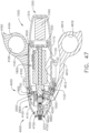
- FIGS. 41-43 depict a clutch system 6000' in accordance with at least one alternative embodiment.
- the clutch system 6000' is similar to the clutch system 6000 in many respects, most of which will not be repeated herein for the sake of brevity.
- the clutch system 6000' comprises a clutch assembly 6100' which is actuatable to selectively couple a rotatable drive input 6030' with a rotatable drive output 6130'.
- the clutch assembly 6100' comprises clutch plates 6110' and drive rings 6120'.
- the clutch plates 6110' are comprised of a magnetic material, such as iron and/or nickel, for example, and can comprise a permanent magnet.
- the clutch plates 6110' are movable between unactuated positions ( FIG. 42 ) and actuated positions ( FIG. 43 ) within the drive output 6130'.
- the clutch plates 6110' are slideably positioned in apertures defined in the drive output 6130' such that the clutch plates 6110' rotate with the drive output 6130' regardless of whether the clutch plates 6110' are in their unactuated or actuated positions.
- the clutch plates 6110' When the clutch plates 6110' are in their unactuated positions, as illustrated in FIG. 42 , the rotation of the drive input 6030' is not transferred to the drive output 6130'. More specifically, when the drive input 6030' is rotated, in such instances, the drive input 6030' slides past and rotates relative to the drive rings 6120' and, as a result, the drive rings 6120' do not drive the clutch plates 6110' and the drive output 6130'.
- the clutch plates 6110' When the clutch plates 6110' are in their actuated positions, as illustrated in FIG. 43 , the clutch plates 6110' resiliently compress the drive rings 6120' against the drive input 6030'.
- the drive rings 6120' are comprised of any suitable compressible material, such as rubber, for example.
- the clutch system 6000' comprises a clutch actuator 6140' configured to move the clutch plates 6110' into their actuated positions.
- the clutch actuator 6140' is comprised of a magnetic material such as iron and/or nickel, for example, and can comprise a permanent magnet.
- the clutch actuator 6140' is slideably positioned in a longitudinal shaft frame 6050' extending through the drive input 6030' and can be moved between an unactuated position ( FIG. 42 ) and an actuated position ( FIG. 43 ) by a clutch shaft 6060'.
- the clutch shaft 6060' comprises a polymer cable, for example.
- FIG. 44 depicts an end effector 7000a including a jaw assembly 71 00a, a jaw assembly drive, and a clutch system 6000a in accordance with at least one alternative embodiment.
- the jaw assembly 7100a comprises a first jaw 7110a and a second jaw 7120a which are selectively rotatable about a pivot 7130a.
- the jaw assembly drive comprises a translatable actuator rod 7160a and drive links 7140a which are pivotably coupled to the actuator rod 7160a about a pivot 7150a.
- the drive links 7140a are also pivotably coupled to the jaws 7110a and 7120a such that the jaws 7110a and 7120a are rotated closed when the actuator rod 7160a is pulled proximally and rotated open when the actuator rod 7160a is pushed distally.
- the clutch system 6000a is similar to the clutch systems 6000 and 6000' in many respects, most of which will not be repeated herein for the sake of brevity.
- the clutch system 6000a comprises a first clutch assembly 6100a and a second clutch assembly 6200a which are configured to selectively transmit the rotation of a drive input 6030a to rotate the jaw assembly 7100a about a longitudinal axis and articulate the jaw assembly 7100a about an articulation joint 7300a, respectively, as described in greater detail below.
- the first clutch assembly 6100a comprises clutch plates 6110a and drive rings 6120a and work in a manner similar to the clutch plates 6110' and drive rings 6120' discussed above.
- the clutch pates 6110a are actuated by an electromagnetic actuator 6140a, the rotation of the drive input 6030a is transferred to an outer shaft housing 7200a.
- the outer shaft housing 7200a comprises a proximal outer housing 7210a and a distal outer housing 7220a which is rotatably supported by the proximal outer housing 7210a and is rotated relative to the proximal outer housing 7210a by the drive input 6030a when the clutch plates 6110a are in their actuated position.
- the rotation of the distal outer housing 7220a rotates the jaw assembly 7100a about the longitudinal axis owing to fact that the pivot 7130a of the jaw assembly 7100a is mounted to the distal outer housing 7220a.
- the outer shaft housing 7200a rotates the jaw assembly 7100a in a first direction when the outer shaft housing 7200a is rotated in a first direction by the drive input 6030a.
- the outer shaft housing 7200a rotates the jaw assembly 7100a in a second direction when the outer shaft housing 7200a is rotated in a second direction by the drive input 6030a.
- the electromagnetic actuator 6140a is de-energized, the drive rings 6120a expand and the clutch plates 6110a are moved into their unactuated positions, thereby decoupling the end effector rotation drive from the drive input 6030a.
- the second clutch assembly 6200a comprises clutch plates 6210a and drive rings 6220a and work in a manner similar to the clutch plates 6110' and drive rings 6120' discussed above.
- the clutch pates 6210a are actuated by an electromagnetic actuator 6240a, the rotation of the drive input 6030a is transferred to an articulation drive 6230a.
- the articulation drive 6230a is rotatably supported within an outer shaft housing 7410a of an end effector attachment portion 7400a and is rotatably supported by a shaft frame 6050a extending through the outer shaft housing 7410a.
- the articulation drive 6230a comprises a gear face defined thereon which is operably intermeshed with a stationary gear face 7230a defined on the proximal outer housing 7210a of the outer shaft housing 7200a.
- the articulation drive 6230a articulates the outer shaft housing 7200a and the jaw assembly 7100a in a first direction when the articulation drive 6230a is rotated in a first direction by the drive input 6030a.
- the articulation drive 6230a articulates the outer shaft housing 7200a and the jaw assembly 7100a in a second direction when the articulation drive 6230a is rotated in a second direction by the drive input 6030a.
- the electromagnetic actuator 6240a is de-energized, the drive rings 6220a expand and the clutch plates 6210a are moved into their unactuated positions, thereby decoupling the end effector articulation drive from the drive input 6030a.
- the proximal portion 4100 comprises a housing 4110 including an attachment interface 4130 configured to mount the shaft assembly 4000 to the attachment interface 1130 of the handle 1000.
- the shaft assembly 4000 further comprises a frame 4500 including a shaft 4510 configured to be coupled to the shaft 1510 of the handle frame 1500 when the shaft assembly 4000 is attached to the handle 1000.
- the shaft assembly 4000 also comprises a drive system 4700 including a rotatable drive shaft 4710 configured to be operably coupled to the drive shaft 1710 of the handle drive system 1700 when the shaft assembly 4000 is attached to the handle 1000.
- the distal attachment portion 2400 is configured to receive an end effector, such as end effector 8000, for example.
- the end effector 8000 is similar to the end effector 7000 in many respects, most of which will not be repeated herein for the sake of brevity. That said, the end effector 8000 comprises a jaw assembly 8100 configured to, among other things, grasp tissue.
- the frame 4500 of the shaft assembly 4000 comprises a frame shaft 4510.
- the frame shaft 4510 comprises a notch, or cut-out, 4530 defined therein.
- the cut-out 4530 is configured to provide clearance for a jaw closure actuation system 4600.
- the frame 4500 further comprises a distal portion 4550 and a bridge 4540 connecting the distal portion 4550 to the frame shaft 4510.
- the frame 4500 further comprises a longitudinal portion 4560 extending through the elongate shaft 4200 to the distal attachment portion 2400. Similar to the above, the frame shaft 4510 comprises one or more electrical traces defined thereon and/or therein.
- the electrical traces extend through the longitudinal portion 4560, the distal portion 4550, the bridge 4540, and/or any suitable portion of the frame shaft 4510 to the electrical contacts 2520.
- the distal portion 4550 and longitudinal portion 4560 comprise a longitudinal aperture defined therein which is configured to receive a rod 4660 of the jaw closure actuation system 4600, as described in greater detail below.
- the drive system 4700 of the shaft assembly 4000 comprises a drive shaft 4710.
- the drive shaft 4710 is rotatably supported within the proximal shaft housing 4110 by the frame shaft 4510 and is rotatable about a longitudinal axis extending through the frame shaft 4510.
- the drive system 4700 further comprises a transfer shaft 4750 and an output shaft 4780.
- the transfer shaft 4750 is also rotatably supported within the proximal shaft housing 4110 and is rotatable about a longitudinal axis extending parallel to, or at least substantially parallel to, the frame shaft 4510 and the longitudinal axis defined therethrough.
- the transfer shaft 4750 comprises a proximal spur gear 4740 fixedly mounted thereto such that the proximal spur gear 4740 rotates with the transfer shaft 4750.
- the proximal spur gear 4740 is operably intermeshed with an annular gear face 4730 defined around the outer circumference of the drive shaft 4710 such that the rotation of the drive shaft 4710 is transferred to the transfer shaft 4750.
- the transfer shaft 4750 further comprises a distal spur gear 4760 fixedly mounted thereto such that the distal spur gear 4760 rotates with the transfer shaft 4750.
- the distal spur gear 4760 is operably intermeshed with an annular gear 4770 defined around the outer circumference of the output shaft 4780 such that the rotation of the transfer shaft 4750 is transferred to the output shaft 4780.
- the output shaft 4780 is rotatably supported within the proximal shaft housing 4110 by the distal portion 4550 of the shaft frame 4500 such that the output shaft 4780 rotates about the longitudinal shaft axis.
- the output shaft 4780 is not directly coupled to the input shaft 4710; rather, the output shaft 4780 is operably coupled to the input shaft 4710 by the transfer shaft 4750.
- Such an arrangement provides room for the manually-actuated jaw closure actuation system 4600 discussed below.
- the jaw closure actuation system 4600 comprises an actuation, or scissors, trigger 4610 rotatably coupled to the proximal shaft housing 4110 about a pivot 4620.
- the actuation trigger 4610 comprises an elongate portion 4612, a proximal end 4614, and a grip ring aperture 4616 defined in the proximal end 4614 which is configured to be gripped by the clinician.
- the shaft assembly 4000 further comprises a stationary grip 4160 extending from the proximal housing 4110.
- the stationary grip 4160 comprises an elongate portion 4162, a proximal end 4164, and a grip ring aperture 4166 defined in the proximal end 4164 which is configured to be gripped by the clinician.
- the actuation trigger 4610 is rotatable between an unactuated position and an actuated position ( FIG. 48 ), i.e., toward the stationary grip 4160, to close the jaw assembly 8100 of the end effector 8000.
- the jaw closure actuation system 4600 further comprises a drive link 4640 rotatably coupled to the proximal shaft housing 4110 about a pivot 4650 and, in addition, an actuation rod 4660 operably coupled to the drive link 4640.
- the actuation rod 4660 extends through an aperture defined in the longitudinal frame portion 4560 and is translatable along the longitudinal axis of the shaft frame 4500.
- the actuation rod 4660 comprises a distal end operably coupled to the jaw assembly 8100 and a proximal end 4665 positioned in a drive slot 4645 defined in the drive link 4640 such that the actuation rod 4660 is translated longitudinally when the drive link 4640 is rotated about the pivot 4650.
- the proximal end 4665 is rotatably supported within the drive slot 4645 such that the actuation rod 4660 can rotate with the end effector 8000.
- the actuation trigger 4610 further comprises a drive arm 4615 configured to engage and rotate the drive link 4640 proximally, and translate the actuation rod 4660 proximally, when the actuation trigger 4610 is actuated, i.e., moved closer to the proximal shaft housing 4110.
- the proximal rotation of the drive link 4640 resiliently compresses a biasing member, such as a coil spring 4670, for example, positioned intermediate the drive link 4640 and the frame shaft 4510.
- a biasing member such as a coil spring 4670
- the distal rotation of the drive link 4640 drives, and automatically rotates, the actuation trigger 4610 back into its unactuated position. That being said, the clinician could manually return the actuation trigger 4610 back into its unactuated position. In such instances, the actuation trigger 4610 could be opened slowly.
- the shaft assembly 4000 further comprises a lock configured to releasably hold the actuation trigger 4610 in its actuated position such that the clinician can use their hand to perform another task without the jaw assembly 8100 opening unintentionally.
- the shaft assembly 4000 has three functions - opening/closing the jaw assembly of an end effector, rotating the end effector about a longitudinal axis, and articulating the end effector about an articulation axis.
- the end effector rotation and articulation functions of the shaft assembly 4000 are driven by the motor assembly 1600 and the control system 1800 of the drive module 1100 while the jaw actuation function is manually-driven by the jaw closure actuation system 4600.
- the jaw closure actuation system 4600 could be a motor-driven system but, instead, the jaw closure actuation system 4600 has been kept a manually-driven system such that the clinician can have a better feel for the tissue being clamped within the end effector.
- motorizing the jaw closure actuation system 4600 may cause the clinician to lose a tactile sense of the force being applied to the tissue and may not be able to assess whether the force is insufficient or excessive. Thus, the jaw closure actuation system 4600 is manually-driven even though the end effector rotation and articulation systems are motor-driven.
- FIG. 50 is a logic diagram of the control system 1800 of the surgical system depicted in FIG. 1 in accordance with at least one embodiment.
- the control system 1800 comprises a control circuit.
- the control circuit includes a microcontroller 1840 comprising a processor 1820 and a memory 1830.
- One or more sensors such as sensors 1880, 1890, 6180', 6280', 6380', 7190", and/or 6290′′′, for example, provide real time feedback to the processor 1820.
- the control system 1800 further comprises a motor driver 1850 configured to control the electric motor 1610 and a tracking system 1860 configured to determine the position of one or more longitudinally movable components in the surgical instrument, such as the clutches 6110, 6120, and 6130 and/or the longitudinally-movable drive nut 7150 of the jaw assembly drive, for example.
- the tracking system 1860 is also configured to determine the position of one or more rotational components in the surgical instrument, such as the drive shaft 2530, the outer shaft 6230, and/or the articulation drive 6330, for example.
- the tracking system 1860 provides position information to the processor 1820, which can be programmed or configured to, among other things, determine the position of the clutches 6110, 6120, and 6130 and the drive nut 7150 as well as the orientation of the jaws 7110 and 7120.
- the motor driver 1850 may be an A3941 available from Allegro Microsystems, Inc., for example; however, other motor drivers may be readily substituted for use in the tracking system 1860. A detailed description of an absolute positioning system is described in U.S. Patent Application Publication No.
- the microcontroller 1840 may be any single core or multicore processor such as those known under the trade name ARM Cortex by Texas Instruments, for example.
- the microcontroller 1840 is a LM4F230H5QR ARM Cortex-M4F Processor Core, available from Texas Instruments, for example, comprising on-chip memory of 256 KB single-cycle flash memory, or other non-volatile memory, up to 40 MHz, a prefetch buffer to improve performance above 40 MHz, a 32 KB single-cycle serial random access memory (SRAM), internal read-only memory (ROM) loaded with StellarisWare ® software, 2 KB electrically erasable programmable read-only memory (EEPROM), one or more pulse width modulation (PWM) modules and/or frequency modulation (FM) modules, one or more quadrature encoder inputs (QEI) analog, one or more 12-bit Analog-to-Digital Converters (ADC) with 12 analog input channels, for example, details of which are available from the product datasheet.
- LM4F230H5QR ARM Cortex-M4F Processor Core available from Texas Instruments, for example, comprising on-chip memory
- the microcontroller 1840 comprises a safety controller comprising two controller-based families such as TMS570 and RM4x known under the trade name Hercules ARM Cortex R4, also by Texas Instruments.
- the safety controller may be configured specifically for IEC 61508 and ISO 26262 safety critical applications, among others, to provide advanced integrated safety features while delivering scalable performance, connectivity, and memory options.
- the microcontroller 1840 is programmed to perform various functions such as precisely controlling the speed and/or position of the drive nut 7150 of the jaw closure assembly, for example.
- the microcontroller 1840 is also programmed to precisely control the rotational speed and position of the end effector 7000 and the articulation speed and position of the end effector 7000.
- the microcontroller 1840 computes a response in the software of the microcontroller 1840.
- the computed response is compared to a measured response of the actual system to obtain an "observed" response, which is used for actual feedback decisions.
- the observed response is a favorable, tuned, value that balances the smooth, continuous nature of the simulated response with the measured response, which can detect outside influences on the system.
- the motor 1610 is controlled by the motor driver 1850.
- the motor 1610 is a DC brushed driving motor having a maximum rotational speed of approximately 25,000 RPM, for example.
- the motor 1610 includes a brushless motor, a cordless motor, a synchronous motor, a stepper motor, or any other suitable electric motor.
- the motor driver 1850 may comprise an H-bridge driver comprising field-effect transistors (FETs), for example.
- FETs field-effect transistors
- the motor driver 1850 may be an A3941 available from Allegro Microsystems, Inc., for example.
- the A3941 driver 1850 is a full-bridge controller for use with external N-channel power metal oxide semiconductor field effect transistors (MOSFETs) specifically designed for inductive loads, such as brush DC motors.
- MOSFETs power metal oxide semiconductor field effect transistors
- the driver 1850 comprises a unique charge pump regulator provides full (>10 V) gate drive for battery voltages down to 7 V and allows the A3941 to operate with a reduced gate drive, down to 5.5 V.
- a bootstrap capacitor may be employed to provide the above-battery supply voltage required for N-channel MOSFETs.
- An internal charge pump for the high-side drive allows DC (100% duty cycle) operation.
- the full bridge can be driven in fast or slow decay modes using diode or synchronous rectification. In the slow decay mode, current recirculation can be through the high-side or the lowside FETs.
- the power FETs are protected from shoot-through by resistor adjustable dead time.
- Integrated diagnostics provide indication of undervoltage, overtemperature, and power bridge faults, and can be configured to protect the power MOSFETs under most short circuit conditions. Other motor drivers may be readily substituted.
- the tracking system 1860 comprises a controlled motor drive circuit arrangement comprising one or more position sensors, such as sensors 1880, 1890, 6180', 6280', 6380', 7190", and/or 6290'", for example.
- the position sensors for an absolute positioning system provide a unique position signal corresponding to the location of a displacement member.
- displacement member is used generically to refer to any movable member of the surgical system.
- the displacement member may be coupled to any position sensor suitable for measuring linear displacement.
- Linear displacement sensors may include contact or non-contact displacement sensors.
- Linear displacement sensors may comprise linear variable differential transformers (LVDT), differential variable reluctance transducers (DVRT), a slide potentiometer, a magnetic sensing system comprising a movable magnet and a series of linearly arranged Hall Effect sensors, a magnetic sensing system comprising a fixed magnet and a series of movable linearly arranged Hall Effect sensors, an optical sensing system comprising a movable light source and a series of linearly arranged photo diodes or photo detectors, or an optical sensing system comprising a fixed light source and a series of movable linearly arranged photo diodes or photo detectors, or any combination thereof.
- LVDT linear variable differential transformers
- DVRT differential variable reluctance transducers
- slide potentiometer a magnetic sensing system comprising a movable magnet and a series of linearly arranged Hall Effect sensors
- a magnetic sensing system comprising a fixed magnet and a series of movable linearly arranged Hall Effect sensors
- the position sensors 1880, 1890, 6180', 6280', 6380', 7190", and/or 6290' may comprise any number of magnetic sensing elements, such as, for example, magnetic sensors classified according to whether they measure the total magnetic field or the vector components of the magnetic field.
- magnetic sensors classified according to whether they measure the total magnetic field or the vector components of the magnetic field.
- the techniques used to produce both types of magnetic sensors encompass many aspects of physics and electronics.
- the technologies used for magnetic field sensing include search coil, fluxgate, optically pumped, nuclear precession, SQUID, Hall-Effect, anisotropic magnetoresistance, giant magnetoresistance, magnetic tunnel junctions, giant magnetoimpedance, magnetostrictive/piezoelectric composites, magnetodiode, magnetotransistor, fiber optic, magnetooptic, and microelectromechanical systems-based magnetic sensors, among others.
- one or more of the position sensors of the tracking system 1860 comprise a magnetic rotary absolute positioning system.
- Such position sensors may be implemented as an AS5055EQFT single-chip magnetic rotary position sensor available from Austria Microsystems, AG and can be interfaced with the controller 1840 to provide an absolute positioning system.
- a position sensor comprises a low-voltage and low-power component and includes four Hall-Effect elements in an area of the position sensor that is located adjacent a magnet.
- a high resolution ADC and a smart power management controller are also provided on the chip.
- a CORDIC processor for Coordinate Rotation Digital Computer, also known as the digit-by-digit method and Volder's algorithm, is provided to implement a simple and efficient algorithm to calculate hyperbolic and trigonometric functions that require only addition, subtraction, bitshift, and table lookup operations.
- the angle position, alarm bits, and magnetic field information are transmitted over a standard serial communication interface such as an SPI interface to the controller 1840.
- the position sensors can provide 12 or 14 bits of resolution, for example.
- the position sensors can be an AS5055 chip provided in a small QFN 16-pin 4x4x0.85mm package, for example.
- the tracking system 1860 may comprise and/or be programmed to implement a feedback controller, such as a PID, state feedback, and adaptive controller.
- a power source converts the signal from the feedback controller into a physical input to the system, in this case voltage.
- Other examples include pulse width modulation (PWM) and/or frequency modulation (FM) of the voltage, current, and force.
- PWM pulse width modulation
- FM frequency modulation
- Other sensor(s) may be provided to measure physical parameters of the physical system in addition to position.
- the other sensor(s) can include sensor arrangements such as those described in U.S. Patent No. 9,345,481 , entitled STAPLE CARTRIDGE TISSUE THICKNESS SENSOR SYSTEM; U.S. Patent Application Publication No.
- absolute positioning system is coupled to a digital data acquisition system where the output of the absolute positioning system will have finite resolution and sampling frequency.
- the absolute positioning system may comprise a compare and combine circuit to combine a computed response with a measured response using algorithms such as weighted average and theoretical control loop that drives the computed response towards the measured response.
- the computed response of the physical system takes into account properties like mass, inertial, viscous friction, inductance resistance, etc., to predict what the states and outputs of the physical system will be by knowing the input.
- the absolute positioning system provides an absolute position of the displacement member upon power up of the instrument without retracting or advancing the displacement member to a reset (zero or home) position as may be required with conventional rotary encoders that merely count the number of steps forwards or backwards that the motor 1610 has taken to infer the position of a device actuator, drive bar, knife, and the like.
- a sensor 1880 comprising a strain gauge or a micro-strain gauge, for example, is configured to measure one or more parameters of the end effector, such as, for example, the strain experienced by the jaws 7110 and 7120 during a clamping operation. The measured strain is converted to a digital signal and provided to the processor 1820.
- a sensor 1890 comprising a load sensor, for example, can measure the closure force applied by the closure drive system to the jaws 7110 and 7120.
- a current sensor 1870 can be employed to measure the current drawn by the motor 1610.
- the force required to clamp the jaw assembly 7100 can correspond to the current drawn by the motor 1610, for example.
- the measured force is converted to a digital signal and provided to the processor 1820.
- a magnetic field sensor can be employed to measure the thickness of the captured tissue. The measurement of the magnetic field sensor can also be converted to a digital signal and provided to the processor 1820.
- the measurements of the tissue compression, the tissue thickness, and/or the force required to close the end effector on the tissue as measured by the sensors can be used by the controller 1840 to characterize the position and/or speed of the movable member being tracked.
- a memory 1830 may store a technique, an equation, and/or a look-up table which can be employed by the controller 1840 in the assessment.
- the controller 1840 can provide the user of the surgical instrument with a choice as to the manner in which the surgical instrument should be operated.
- the display 1440 can display a variety of operating conditions of the instrument and can include touch screen functionality for data input.
- information displayed on the display 1440 may be overlaid with images acquired via the imaging modules of one or more endoscopes and/or one or more additional surgical instruments used during the surgical procedure.
- the drive module 1100 of the handle 1000 and/or the shaft assemblies 2000, 3000, 4000, and/or 5000, for example, attachable thereto comprise control systems.
- Each of the control systems can comprise a circuit board having one or more processors and/or memory devices.
- the control systems are configured to store sensor data, for example. They are also configured to store data which identifies the shaft assembly to the handle 1000. Moreover, they are also configured to store data including whether or not the shaft assembly has been previously used and/or how many times the shaft assembly has been used. This information can be obtained by the handle 1000 to assess whether or not the shaft assembly is suitable for use and/or has been used less than a predetermined number of times, for example.
- a drive module 1100' in accordance with at least one alternative embodiment is illustrated in FIGS. 51-53 .
- the drive module 1100' is similar to the drive module 1100 in many respects, most of which will not be discussed herein for the sake of brevity.
- the drive module 1100' comprises an actuator 1420' configured to control the rotation and articulation of the end effector 7000. Similar to the actuator 1420, discussed above, the actuator 1420' is rotatable about a longitudinal axis LA that extends through a shaft assembly attached to the drive module 1100.
- the longitudinal axis LA extends through the center, or substantially the center, of the elongate shaft 2200 of the shaft assembly 3000 ( FIG. 1 ) when the shaft assembly 3000 is assembled to the drive module 1100'.
- the longitudinal axis LA also extends through the center, or substantially the center, of the end effector 7000 when the end effector 7000 is attached to the shaft assembly 3000, for example.
- the actuator 1420' is rotatable within a channel 1190' defined in the housing 1110 in a first direction to rotate the end effector 7000 in the first direction and, similarly, in a second, or opposite, direction to rotate the end effector 7000 in the second direction.
- the drive module 1100' comprises a sensor system in communication with the control system 1800 configured to detect the rotation of the actuator 1420' about the longitudinal axis LA.
- the sensor system comprises a first sensor 1422' configured to detect the rotation of the actuator 1420' about the longitudinal axis LA in the first direction ( FIG. 52A ) and a second sensor 1424' configured to detect the rotation of the actuator 1420' about the longitudinal axis LA in the second direction ( FIG.
- the first and second sensors 1422' and 1424' comprise Hall Effect sensors, for example, but could comprise any suitable type of sensor.
- the actuator 1420' comprises a center magnetic element 1426' positioned in the top of the actuator 1420' which is detectable by the first and second sensors 1422' and 1424' to determine the rotation of the actuator 1420'.
- the center magnetic element 1426' can comprise a permanent magnet and/or can be comprised of iron and/or nickel, for example.
- control system 1800 is configured to control the motor assembly 1600 and the clutch system 6000 to rotate the end effector 7000 about the longitudinal axis LA in the first direction when the actuator 1420' is rotated about the longitudinal axis LA in the first direction.
- control system 1800 is configured to control the motor assembly 1600 and the clutch system 6000 to rotate the end effector 7000 about the longitudinal axis LA in the second direction when the actuator 1420' is rotated about the longitudinal axis LA in the second direction.
- the end effector 7000 is configured to rotate about a longitudinal axis within a socket defined in the distal attachment portion 2400 of the shaft assembly 2000. Depending on the amount of rotation desired, the end effector 7000 can be rotated less than 360 degrees or more than 360 degrees in either direction. In various instances, the end effector 7000 can be rotated through several rotations in either direction. In alternative embodiments, the rotation of the end effector 7000 about the longitudinal axis can be limited. In at least one embodiment, the shaft assembly 2000 comprises one or more stops which limit the rotation of the end effector 7000 to less than one rotation.
- control system 1800 monitors the rotation of the drive shaft 1710, such as by an encoder and/or an absolute positioning sensor system, for example, and limits the rotation of the end effector 7000 by stopping or pausing the motor 1610 when the end effector 7000 has reached the end of its permitted range. In at least one instance, the control system 1800 can disengage the second clutch 6210 from the drive shaft 2730 to stop or pause the rotation of the end effector 7000 when the end effector 7000 has reached the end of its permitted range.
- the drive module 1100' and/or a shaft module attached to the drive module 1100' can provide feedback to the clinician that the end effector 7000 has reached the end of its rotation.
- the drive module 1100' and/or the shaft module attached thereto can comprise an indicator light 1427', such as a red LED, for example, on a first side of the module housing 1110' which is illuminated by the control system 1800 when the end effector 7000 has reached the end of its permitted rotation in the first direction, as illustrated in FIG. 52A .
- the first and second tilt sensors 1423' and 1425' comprise Hall Effect sensors, for example, but could comprise any suitable type of sensor.
- the actuator 1420' further comprises a first lateral magnetic element adjacent the first tilt sensor 1423', the motion of which is detectable by the first tilt sensor 1423'.
- the actuator 1420' also comprises a second lateral magnetic element adjacent the second tilt sensor 1425', the motion of which is detectable by the second tilt sensor 1425'.
- the first and second lateral magnetic elements can comprise a permanent magnet and/or can be comprised of iron and/or nickel, for example. As illustrated in FIGS.
- the control system 1800 operates the motor assembly 1600 and the clutch system 6000 to articulate the end effector 7000 about the articulation joint 2300 in the first direction.
- the control system 1800 operates the motor assembly 1600 and the clutch system 6000 to articulate the end effector 7000 about the articulation joint 2300 in the second direction when the sensor system detects that the actuator 1420' has been tilted in the second direction, as illustrated in FIG. 53B .
- the actuator 1420' comprises a biasing system configured to center the actuator 1420' in its unrotated and untilted position.
- the biasing system comprises first and second rotation springs configured to center the actuator 1420' in its unrotated position and first and second tilt springs configured to center the actuator 1420' in its untilted position.
- These springs can comprise torsion springs and/or linear displacement springs, for example.
- the end effector 7000 rotates relative to the distal attachment portion 2400 of the shaft assembly 3000.
- Such an arrangement allows the end effector 7000 to be rotated without having to rotate the shaft assembly 3000, although embodiments are possible in which an end effector and shaft assembly rotate together. That said, by rotating the end effector 7000 relative to the shaft assembly 3000, all of the rotation of the surgical system occurs distally relative to the articulation joint 2300. Such an arrangement prevents a large sweep of the end effector 7000 when the end effector 7000 is articulated and then rotated.
- the tiltable actuator 1420' is only used to control the articulation of the end effector 7000 and is not rotatable about the longitudinal axis LA. Rather, in such embodiments, the actuator 1420' is only rotatable about the transverse axis TA.
- the housing of the drive module 1100' comprises two posts 1421' ( FIG. 51 ) about which the actuator 1120' is rotatably mounted which defines the transverse axis TA. The posts 1421' are aligned along a common axis.
- Surgical instruments such as surgical dissectors have been in widespread use in various surgical procedures. These instruments allow a surgeon to manipulate, separate, and remove specific areas of tissue of a patient. Having the ability to develop custom dissectors for specific surgical procedures and for a patient's physiological conditions can be of great value.
- the surgical end effector 100000 can comprise a solid customizable region 100002.
- the solid customizable region 100002 can be made of various materials such as various metals and/or plastics, for example.
- the surgeon can use a manufacturing technique to remove the excess material to leave the desired shape of the customizable jaw 100012.
- the surgeon may start with a surgical end effector 100000 that does not have a core/stub portion 100100 and, instead, only has a standard connector portion 100050. With just the standard connector portion 100050, the surgeon can use a manufacturing process to create the desired shape and features of the customized jaw 100012 within the bounds of the customization region 100002.
- a surgical instrument may have a surgical end effector 100100, as illustrated in FIG. 59 .
- the surgical end effector 100100 has a standard connection portion 100150 and a customizable end effector portion 100160.
- the standard connection portion 100150 includes a first jaw portion 100106 and a second jaw portion 100108.
- the first jaw portion 100106 and the second jaw portion 100108 are rotatable about a joint 100104.
- the standard connection portion 100150 of the surgical end effector 100100 can be connected to a shaft of a surgical instrument.
- the shaft of the surgical instrument can have a diameter D.
- the customizable end effector portion 100160 can be customized within the customization region 100102 such that the diameter of the customization region 100102 is equal to or less than the diameter D of the shaft of the surgical instrument. With the customizable end effector portion 100160 being confined to the bounds of the customization region 100102, the surgical end effector 100100 can be inserted through a trocar into a patient's body cavity through minimally invasive surgical procedures.
- the first jaw portion 100306 of the end effector portion 100360 includes a core/stub portion 100310 that is adaptable through additive manufacturing techniques.
- the core/stub portion 100310 provides a base for building and customizing the geometry and characteristics of a first customizable jaw 100312 and a second customizable jaw 100314.
- the first customizable jaw 100312 and the second customizable jaw 100314 can be modified and adapted to meet the needs of the surgeon.
- the first customizable jaw 100312 and the second customizable jaw 100314 have a plurality of proximal features 100318 and a plurality of distal features 100316. As illustrated in FIG. 61 , the plurality of proximal features 100318 comprises a plurality of proximal teeth.
- the plurality of distal features 100416 comprises a plurality of distal teeth.
- the plurality of proximal teeth is approximately the same height as the plurality of distal teeth.
- the plurality of proximal and distal teeth may take various configurations based upon the needs of the surgical procedure such as, for example, a plurality of symmetrical teeth, a plurality of asymmetrical teeth, and/or a progression from large to small or small to large teeth.
- the external features 100430, 100432, the proximal features 100418, the distal features 100416, the overall geometric shape of the first and second customizable jaws 100412, 100414, and the materials used in producing the customizable end effector portion 100460 are independent variables that are considered during the customization process.
- the various independent variables must result in an overall profile that falls within the customization region 100402 so that the surgical end effector 100400 can be inserted through a trocar and into a patient's body cavity.
- the customizable end effector portion 100560 can be customized within a customization region 100502, such that the diameter of the customization region 100502 is equal to or less than the diameter D of the shaft of the surgical instrument. With the customizable end effector portion 100560 being confined to the bounds of the customization region 100502, the surgical end effector 100500 can be inserted through a trocar into a patient's body cavity through minimally invasive surgical procedures.
- the customizable end effector portion 100560 can be produced through various additive manufacturing techniques to produce custom geometry and characteristics of a first customizable jaw 100512 and a second customizable jaw 100514. Depending on various needs for the surgical procedure, the first customizable jaw 100512 and the second customizable jaw 100514 can be modified and adapted to meet the needs of the surgeon.
- the first customizable jaw 100512 and the second customizable jaw 100514 have a plurality of proximal features 100518 and a plurality of distal features 100516. As illustrated in FIG. 64 , the plurality of proximal features 100518 comprises a plurality of small symmetrical proximal teeth.
- the plurality of distal features 100516 comprises a plurality of small symmetrical distal teeth.
- the customizable end effector portion 100660 can be customized within a customization region 100602, such that the diameter of the customization region 100602 is equal to or less than the diameter D of the shaft of the surgical instrument. With the customizable end effector portion 100660 being confined to the bounds of the customization region 100602, the surgical end effector 100600 can be inserted through a trocar into a patient's body cavity through minimally invasive surgical procedures.
- FIG. 66 illustrates a surgical end effector 100700 that is configured to be modified and adjusted using various manufacturing techniques at the discretion of a surgeon.
- the surgical end effector 100700 includes a standard connection portion 100750 and a customizable end effector portion 100760.
- the standard connection portion 100750 includes a first jaw portion 100706 and a second jaw portion 100708.
- the first jaw portion 100706 and the second jaw portion 100708 are rotatable about a joint 100704.
- the customizable end effector portion 100760 can be customized within a customization region 100702.
- the diameter of the customization region 100702 is equal to or less than the diameter D of the shaft of the surgical instrument. With the customizable end effector portion 100760 being confined to the bounds of the customization region 100702, the surgical end effector 100700 can be inserted through a trocar into a patient's body cavity through minimally invasive surgical procedures.
- the plurality of smooth distal teeth is only formed on a portion of the inner surfaces of the first customizable jaw 100712 and the second customizable jaw 100714.
- the first customizable jaw 100712 and the second customizable jaw 100714 comprise external surface features 100730, 100732, respectively.
- the external surface features 100730, 100732 comprise substantially smooth surfaces.
- the external surface features 100730, 100732 may comprise teeth, nubs, and/or other protrusions to assist with the tissue interaction of the surgical end effector 100700.
- FIG. 67 illustrates a surgical end effector 100800 that is configured to be modified and adjusted using various manufacturing techniques at the discretion of a surgeon.
- the surgical end effector 100800 includes a standard connection portion 100850 and a customizable end effector portion 100860.
- the standard connection portion 100850 can include a first jaw portion 100806 and a second jaw portion 100808.
- the first jaw portion 100806 and the second jaw portion 100808 are rotatable about a joint 100804.
- the customizable end effector portion 100860 can be customized within a customization region 100802, such that the diameter of the customization region 100802 is equal to or less than the diameter D of the shaft of the surgical instrument. With the customizable end effector portion 100860 being confined to the bounds of the customization region 100802, the surgical end effector 100800 can be inserted through a trocar into a patient's body cavity through minimally invasive surgical procedures.
- FIGS. 68 and 69 illustrate another embodiment of a surgical end effector 100900.
- the surgical end effector 100900 is configured to be modified and adjusted using various manufacturing techniques at the discretion of a surgeon.
- the surgical end effector 100900 includes a standard connection portion 100950 and a customizable end effector portion 100960.
- the standard connection portion 100950 can include a first jaw portion 100906 and a second jaw portion 100908.
- the first jaw portion 100906 and the second jaw portion 100908 are rotatable about a joint 100904.
- the plurality of distal features 100916 comprises a plurality of distal teeth.
- the plurality of proximal teeth is approximately the same height as the plurality of distal teeth.
- the plurality of proximal and distal teeth may take various configurations based upon the needs of the surgical procedure, for example a plurality of symmetrical teeth, a plurality of asymmetrical teeth, and/or a progression from large to small or small to large teeth.
- the external features 100930, 100932, the proximal features 100918, the distal features 100916, the overall geometric shape of the first and second customizable jaws 100912, 100914, and the materials used in producing the customizable end effector portion 100960 are independent variables that are considered during the customization process.
- the various independent variables must produce an overall profile of the surgical instrument that falls within the customization region 100902 so that the surgical end effector 100900 can be inserted through a trocar and into a patient's body cavity.
- FIGS. 70 and 71 illustrate another embodiment of a surgical end effector 101000.
- the surgical end effector 101000 is configured to be modified and adjusted using various manufacturing techniques at the discretion of a surgeon.
- the surgical end effector 101000 includes a standard connection portion 101050 and a customizable end effector portion 101060.
- the standard connection portion 101050 can include a first jaw portion 101006 and a second jaw portion 101008.
- the first jaw portion 101006 and the second jaw portion 101008 are rotatable about a joint 101004.
- the customizable end effector portion 101060 can be customized within the customization region 101002.
- the diameter of the customization region 101002 is equal to or less than the diameter D of the shaft of the surgical instrument. With the customizable end effector portion 101060 being confined to the bounds of the customization region 101002, the surgical end effector 101000 can be inserted through a trocar into a patient's body cavity through minimally invasive surgical procedures.
- the surgical end effector 101000 includes a core/stub portion 101010 that is adaptable through additive manufacturing techniques.
- the core/stub portion 101010 provides a base for building and customizing the geometry and characteristics of a first customizable jaw 101012 and a second customizable jaw 101014.
- the first customizable jaw 101012 and the second customizable jaw 101014 can be modified and adapted to meet the needs of the surgeon.
- the first customizable jaw 101012 and the second customizable jaw 101014 have a plurality of proximal features 101018 and a plurality of distal features 101016. As illustrated in FIG. 71 , the plurality of proximal features 101018 comprises a plurality of proximal teeth.
- the plurality of distal features 101016 comprises a plurality of distal teeth.
- the plurality of proximal teeth is approximately the same height as the plurality of distal teeth.
- the plurality of proximal and distal teeth may take various configurations based upon the needs of the surgical procedure such as, for example, a plurality of symmetrical teeth, a plurality of asymmetrical teeth, and/or a progression from large to small or small to large teeth.
- first customizable jaw 101012 and the second customizable jaw 101014 have a plurality of features 101030a-d and 101032a-d, respectively that are positioned on the outer portion of the first and second customizable jaws 101012, 101014.
- the features 101030a and 101032a comprise distal concave features.
- the features 101030a and 101032a can have a low durometer surface that is sticky to the touch and can be used to manipulate an object, such as tissue.
- the low-durometer features 101030a and 101032a have a durometer between about 15 and about 70 Shore OO, for example.
- the low-durometer features 101030a and 101032a have a durometer between about 15 and about 70 Shore A, for example.
- the features 101030b and 101032b comprise convex protruding features.
- the features 101030b and 101032b can have a low durometer surface that is sticky to the touch and can be used to manipulate an object, such as tissue.
- the low-durometer features 101030b and 101032b have a durometer between about 15 and about 70 Shore OO, for example.
- the low-durometer features 101030b and 101032b have a durometer between about 15 and about 70 Shore A, for example.
- the features 101030c and 101032c comprise concave features.
- the features 101030c and 101032c can have a low durometer surface that is sticky to the touch and can be used to manipulate an object, such as tissue.
- the features 101030d and 101032d comprise a substantially smooth surface.
- the features 101030d and 101032d can have a low durometer surface that is sticky to the touch and can be used to manipulate an object, such as tissue.
- the feature 101030a-d and 101032a-d can include ridges, and/or substantially smooth surfaces that allow the surgical end effector 101000 to engage, grasp, and/or manipulate an object, for example a patient's tissue.
- FIG. 70 depicts a top plan view of the surgical end effector 101000.
- FIG. 71 depicts a side elevation view of the surgical end effector 101000.
- the overall geometric shape of the surgical end effector 101000 is a substantially linear configuration.
- the external features 101030a-d, 101032a-d, the proximal features 101018, the distal features 101016, the overall geometric shape of the first and second customizable jaws 101012, 101014, and the materials used in producing the customizable end effector portion 101060 are independent variables that are considered during the customization process.
- the various independent variables must produce an overall profile that falls within the customization region 101002 so that the surgical end effector 101000 can be inserted through a trocar and into a patient's body cavity.
- the various end effectors described above with respect to FIGS. 58-71 can be produced through a multi-step process where a first portion of the end effector, such as, a standard connection portion, for example, is produced in a manufacturing facility and shipped to hospitals or distributed to manufacturing hubs. Once the standard connection portion is at its end location, such as a hospital, or at a manufacturing facility, the standard connection portion can be customized to produce an end effector meeting the needs of the user. Such customization can allow surgical end effectors to be produced for specific procedures and/or specific patients.
- the customized end effectors described above with respect to FIGS. 58-71 can be produced through various techniques.
- a clinician can access, for example, a dedicated human-machine interface to select and design the desired attributes of an end effector.
- the human-machine interface can comprise, for example, a graphical user interface of a computer.
- the computer can be connected to a manufacturing device.
- the computer-manufacturing device interface can be wired, wireless, and/or remote, for example, via the internet.
- the clinician can use information gained from the patient or information about the particular procedure to guide their design of the end effector.
- the clinician is using information regarding a particular patient, for example, the patient's information can come from various patient tests, such as MRIs, X-rays, CT Scans, and/or other medical tests. These testing results can be entered into the computer and used to control the design parameters of the end effector.
- the clinician uses the results of an MRI, for example, to detect a patient's tumor, the size and shape of the patient's tumor can be used as design parameters when producing the customized end effector.
- the clinician can use parameters from the particular surgical procedure to design the customized end effector.
- the requirements of the specific procedure such as the size of a gastric bypass reduction, can be used as the design parameters when producing the customized end effector.
- the clinician can use various software programs to design the desired features of the end effector.
- the clinician for example, can input the patient's scans and/or medical test information into the computer and a software program can determine the design features of the end effector to match the patient's condition. Once the software program approximates the necessary features of the end effector, the clinician can review and/or modify the parameters of the end effector using the human-machine interface.
- the clinician can access a software program using the human-machine interface to design the features of the end effector.
- the clinician can access the software program and select various predetermined shapes, features, and/or designs to combine to produce an end effector having the desired features.
- the clinician may also use a free-form command in the software to freely design the desired features of the end effector.
- the clinician and/or manufacturing staff can insert a core/stub portion into a manufacturing device.
- the manufacturing device is in communication with the human-machine interface of the computer via a wired, wireless, and/or remote internet connection.
- the clinician using the software program, can send the design parameters to the manufacturing device to produce the end effector.
- the manufacturing device can be designed to use various manufacturing processes or techniques.
- the manufacturing device for example, can be a metal injection molding device, a plastic injection molding device, a CNC machine, an EDM device, a 3-D printing device, and/or various other manufacturing devices, such as additive manufacturing devices.
- the software controlling the manufacturing device causes the manufacturing device to perform a manufacturing procedure to produce the customized end effector.
- the manufacture procedure can add material to the core/stub portion of the end effector.
- the manufacturing procedure can remove material from the core/stub portion of the end effector.
- the manufacturing device can use one or more of the techniques described above in the production of the customized end effector.
- the customized end effector can be finished or polished using a finishing machine and/or process.
- the finishing machine may be part of the manufacturing device, or it can be a separate machine/device.
- the customized end effector can be tested, cleaned, and/or sterilized.
- the testing process can ensure that the customized end effector is designed to the necessary standards for the particular medical device.
- the cleaning process can remove any excess residual material leftover from the manufacturing process.
- the sterilization process can sterilize the end effector so that it can be used in a surgical procedure. After the customized end effector is sterilized, it can be packaged for storing until it is needed in a surgical procedure or can be used directly by a clinician in a surgical procedure.
- a method for producing a customized end effector comprises preparing an end effector connection portion for customization.
- the end effector connection portion comprises a proximal connector configured to attach to a distal end of a surgical instrument.
- the proximal connector comprises an actuator.
- Surgical instruments can comprise devices that use mechanical energy to perform surgical procedures.
- Certain end effectors such as grasping forceps can be used to grasp a target, such as the tissue of a patient, for example.
- Other end effectors such as dissectors, for example, can be used to separate and/or tear the tissue using mechanical forces.
- Other types of end effectors such as electrosurgical end effectors, for example, can use electrosurgical energy to deliver energy to the tissue of a patient and destroy and/or remove targeted tissue.
- Surgical dissectors comprise a pair of jaws that are rotatable between open and closed positions.
- Each jaw can comprise a plurality of features, such as teeth or ridges that can engage a patient's tissue on inner and/or outer surfaces of the jaw, for example.
- the features, such as teeth, on the inner surfaces of a pair of surgical dissector jaws can be used to gasp and/or manipulate tissue when the jaws are closed upon a portion of the patient's tissue.
- a pair of surgical dissector jaws comprise teeth and/or ridges on outer surfaces thereof, such teeth can increase the traction and interaction between the jaws and the patient's tissue when the jaws are moved into an open position, for example.
- Electrosurgical devices for applying electrical energy to tissue in order to treat and/ or destroy the tissue are finding increasingly widespread applications in surgical procedures.
- An electrosurgical device typically includes a handpiece and an instrument having a distally-mounted end effector (e.g., one or more electrodes). The end effector can be positioned against the tissue such that electrical current is introduced into the tissue.
- Electrosurgical devices can be configured for bipolar and/or monopolar operation. During bipolar operation, current is introduced into and returned from the tissue by active and return electrodes, respectively, of the end effector.
- an active electrode of the end effector During monopolar operation, current is introduced into the tissue by an active electrode of the end effector and returned through a return electrode (e.g., a grounding pad) separately located on a patient's body. Heat generated by the current flowing through the tissue may form hemostatic seals within the tissue and/ or between tissues and thus may be particularly useful for sealing blood vessels, for example. In some instances, the voltage and current used ablates the tissue.
- the end effector of an electrosurgical device also may include a cutting member that is movable relative to the tissue and the electrodes to transect the tissue. Electrical energy applied by an electrosurgical device can be transmitted to the instrument by a generator in communication with the handpiece.
- the electrical energy may be in the form of radio frequency (RF) energy that may be in a frequency range described in EN 60601-2-2:2009+A11:2011, Definition 201.3.218 - HIGH FREQUENCY.
- RF radio frequency
- the frequencies in monopolar RF applications are typically restricted to less than 5MHz, for example.
- the frequency can be any suitable frequency. Frequencies above 200 kHz can be typically used for monopolar applications in order to avoid the unwanted stimulation of nerves and muscles which would result from the use of low frequency current, for instance. Lower frequencies may be used for bipolar techniques if the risk analysis shows the possibility of neuromuscular stimulation has been mitigated to an acceptable level.
- RF energy works particularly well on connective tissue, which is primarily comprised of collagen and shrinks when contacted by heat.
- Other electrical surgical instruments include, without limitation, irreversible and/ or reversible electroporation, and/or microwave technologies, among others.
- the techniques disclosed herein are applicable to ultrasonic, bipolar or monopolar RF (electrosurgical), irreversible and/or reversible electroporation, and/or microwave-based surgical instruments, among others.
- U.S. Patent Application Publication No. 2017/0086914 A1 to Wiener, et al.
- FIGS. 72-79 illustrate surgical instruments that comprise the mechanical features of surgical dissectors and the electrosurgical features of electrosurgical devices.
- the combination of surgical dissector and electrosurgical instrument can allow the surgical instruments illustrated in FIGS. 72-79 to perform various surgical procedures.
- the combination of the mechanical and electrosurgical features may allow a surgeon to perform a surgical procedure without having to switch between different surgical instruments. As discussed in greater detail below with respect to FIG.
- FIGS. 72-79 illustrate various end effector jaws comprising mechanical dissector features and electrosurgical device features. These end effector jaws can be used with surgical instruments to deliver mechanical as well as electrical energy to a patient's tissue.
- the surgical instruments can comprise proximal and distal end effector portions.
- the proximal portion may include a user interface, such as a handle portion and/or a connector that can connect the surgical instrument to a robotic system, for example.
- the distal portion of the surgical instruments can comprise a surgical end effector.
- the surgical end effector can comprise a pair of jaws that are rotatable between open and closed positions.
- FIGS. 72-79 illustrate an end effector jaw that can be used in a pair of jaws of a surgical end effector.
- FIGS. 72-75 illustrate a surgical end effector jaw 101100 comprising a frame 101102, a metallic core 101130, and a covering 101126.
- the end effector jaw 101100 comprises an inner surface 101118 and an outer surface 101108.
- the inner surfaces 101118 of the end effector jaws 101100 are positioned adjacent one another.
- the outer surfaces, 101108 of the end effector jaw 101100 are positioned on opposite sides of the end effector jaw 101100.
- the surgical end effector jaw 101100 comprises a proximal portion 101106 and a distal portion 101110.
- the overall geometry of the end effector jaw 101100 is curved between the proximal portion 101106 and the distal portion 101110.
- the end effector jaw 101100 is tapered from the wider proximal portion 101106 to the narrower distal portion 101110.
- the tapered profile of the end effector jaw 101100 can permit a surgeon to target a specific location within a patient.
- the proximal portion 101106 of the outer surface 101108 comprises a substantially smooth surface.
- the substantially smooth surface can refer to a surface, for example, that is substantially free from projections or unevenness, generally flat or unruffled, and/or substantially of uniform consistency.
- the distal portion 101110 of the outer surface 101108 comprises a plurality of features.
- the plurality of features comprises central features 101120, peripheral features 101122, and lateral features 101132, and/or any other suitable features.
- the distal most portion of the inner surface 101118 comprises a distal bumper portion 101124 and a distal tip 101128.
- the distal bumper portion 101124 comprises an elastic and/or deformable material that can allow the end effector jaw 101100 to interact with a target object with less irritation to the object.
- the distal tip 101128 comprises the metallic core 101130 and is configured to deliver electrosurgical energy to a target object, such as a patient's tissue.
- the distal bumper portion 101124 being constructed of a more elastic and less rigid material can allow the user of the surgical end effector jaw 101100 to be more aggressive without increasing the irritation of the target object, such as a patient's tissue.
- the jaws of the end effector 128030 are driven by a jaw drive system including an electric motor.
- a voltage potential is applied to the electric motor to rotate the drive shaft of the electric motor and drive the jaw drive system.
- the surgical system 128000 comprises a motor control system configured to apply the voltage potential to the electric motor.
- the motor control system is configured to apply a constant DC voltage potential to the electric motor.
- the electric motor will run at a constant speed, or an at least substantially constant speed.
- the motor control system comprises a pulse width modulation (PWM) circuit and/or a frequency modulation (FM) circuit which can apply voltage pulses to the electric motor.
- PWM and/or FM circuits can control the speed of the electric motor by controlling the frequency of the voltage pulses supplied to the electric motor, the duration of the voltage pulses supplied to the electric motor, and/or the duration between the voltage pulses supplied to the electric motor.
- control system can be configured to measure the jaw loading force directly by one or more load cells and/or strain gauges, for example. Once the loading force experienced by the jaws 128740 and 128750 drops below the force threshold Fc, the control system can adaptively speed up the jaw closure rate. Alternatively, the control system can maintain the lower closure rate of the jaws 128740 and 128750 even though the force threshold is no longer being exceeded.
Landscapes
- Health & Medical Sciences (AREA)
- Surgery (AREA)
- Life Sciences & Earth Sciences (AREA)
- Engineering & Computer Science (AREA)
- Medical Informatics (AREA)
- General Health & Medical Sciences (AREA)
- Biomedical Technology (AREA)
- Heart & Thoracic Surgery (AREA)
- Nuclear Medicine, Radiotherapy & Molecular Imaging (AREA)
- Molecular Biology (AREA)
- Animal Behavior & Ethology (AREA)
- Veterinary Medicine (AREA)
- Public Health (AREA)
- Physics & Mathematics (AREA)
- Plasma & Fusion (AREA)
- Otolaryngology (AREA)
- Ophthalmology & Optometry (AREA)
- Robotics (AREA)
- Surgical Instruments (AREA)
Description
- The present invention relates to surgical instruments that are designed to grasp the tissue of a patient.
-
US2014/214019 discloses an apparatus comprising a first jaw, a second jaw, a first handle, and a second handle. The second jaw is pivotally coupled with the first jaw. The first jaw and the second jaw are configured to grasp tissue. The jaws provide offset electrode surfaces that are operable to deliver bipolar RF energy to tissue grasped between the jaws. The apparatus is further operable to sever tissue. A lockout feature selectively prevents tissue severing, based on an energization state of the jaws. -
US5396900 discloses a non-metallic end effector for use in an endoscopic surgical tool which includes a metallic core for strength and for providing a selected electrode surface on the end effector. Selectively conductive end effectors are manufactured by insert molding a plastic or ceramic or other non-conductive body around a metallic or otherwise conductive core. The conductive core is exposed on a selected portion of the working surface of the end effector and extends through the non-conductive body of the end effector for coupling to an electrical source. -
EP2614789 discloses a method of manufacturing an end effector for a surgical instrument which includes providing a substrate wherein at least an outer periphery of the substrate is formed from an electrically insulative material. The method further includes forming at least one ridge on the outer periphery of the substrate and depositing an electrically conductive material onto the at least one ridge to form at least one electrode. -
US9717548 - The present invention is defined by appended
independent claim 1. Optional embodiments of the invention are provided in the dependent claims. - Various features of the embodiments described herein, together with advantages thereof, may be understood in accordance with the following description taken in conjunction with the accompanying drawings as follows:
-
FIG. 1 illustrates a surgical system comprising a handle and several shaft assemblies - each of which are selectively attachable to the handle in accordance with at least one embodiment; -
FIG. 2 is an elevational view of the handle and one of the shaft assemblies of the surgical system ofFIG. 1 ; -
FIG. 3 is a partial cross-sectional perspective view of the shaft assembly ofFIG. 2 ; -
FIG. 4 is another partial cross-sectional perspective view of the shaft assembly ofFIG. 2 ; -
FIG. 5 is a partial exploded view of the shaft assembly ofFIG. 2 ; -
FIG. 6 is a partial cross-sectional elevational view of the shaft assembly ofFIG. 2 ; -
FIG. 7 is an elevational view of a drive module of the handle ofFIG. 1 ; -
FIG. 8 is a cross-sectional perspective view of the drive module ofFIG. 7 ; -
FIG. 9 is an end view of the drive module ofFIG. 7 ; -
FIG. 10 is a partial cross-sectional view of the interconnection between the handle and shaft assembly ofFIG. 2 in a locked configuration; -
FIG. 11 is a partial cross-sectional view of the interconnection between the handle and shaft assembly ofFIG. 2 in an unlocked configuration; -
FIG. 12 is a cross-sectional perspective view of a motor and a speed reduction gear assembly of the drive module ofFIG. 7 ; -
FIG. 13 is an end view of the speed reduction gear assembly ofFIG. 12 ; -
FIG. 14 is a partial perspective view of an end effector of the shaft assembly ofFIG. 2 in an open configuration; -
FIG. 15 is a partial perspective view of the end effector ofFIG. 14 in a closed configuration; -
FIG. 16 is a partial perspective view of the end effector ofFIG. 14 articulated in a first direction; -
FIG. 17 is a partial perspective view of the end effector ofFIG. 14 articulated in a second direction; -
FIG. 18 is a partial perspective view of the end effector ofFIG. 14 rotated in a first direction; -
FIG. 19 is a partial perspective view of the end effector ofFIG. 14 rotated in a second direction; -
FIG. 20 is a partial cross-sectional perspective view of the end effector ofFIG. 14 detached from the shaft assembly ofFIG. 2 ; -
FIG. 21 is an exploded view of the end effector ofFIG. 14 illustrated with some components removed; -
FIG. 22 is an exploded view of a distal attachment portion of the shaft assembly ofFIG. 2 ; -
FIG. 22A is an exploded view of the distal portion of the shaft assembly ofFIG. 2 illustrated with some components removed; -
FIG. 23 is another partial cross-sectional perspective view of the end effector ofFIG. 14 detached from the shaft assembly ofFIG. 2 ; -
FIG. 24 is a partial cross-sectional perspective view of the end effector ofFIG. 14 attached to the shaft assembly ofFIG. 2 ; -
FIG. 25 is a partial cross-sectional perspective view of the end effector ofFIG. 14 attached to the shaft assembly ofFIG. 2 ; -
FIG. 26 is another partial cross-sectional perspective view of the end effector ofFIG. 14 attached to the shaft assembly ofFIG. 2 ; -
FIG. 27 is a partial cross-sectional view of the end effector ofFIG. 14 attached to the shaft assembly ofFIG. 2 depicting a first, second, and third clutch of the end effector; -
FIG. 28 depicts the first clutch ofFIG. 27 in an unactuated condition; -
FIG. 29 depicts the first clutch ofFIG. 27 in an actuated condition; -
FIG. 30 depicts the second clutch ofFIG. 27 in an unactuated condition; -
FIG. 31 depicts the second clutch ofFIG. 27 in an actuated condition; -
FIG. 32 depicts the third clutch ofFIG. 27 in an unactuated condition; -
FIG. 33 depicts the third clutch ofFIG. 27 in an actuated condition; -
FIG. 34 depicts the second and third clutches ofFIG. 27 in their unactuated conditions and the end effector ofFIG. 14 locked to the shaft assembly ofFIG. 2 ; -
FIG. 35 depicts the second clutch ofFIG. 27 in its unactuated condition and the third clutch ofFIG. 27 in its actuated condition; -
FIG. 36 depicts the second and third clutches ofFIG. 27 in their actuated conditions and the end effector ofFIG. 14 unlocked from the shaft assembly ofFIG. 2 ; -
FIG. 37 is a partial cross-sectional view of a shaft assembly in accordance with at least one alternative embodiment comprising sensors configured to detect the conditions of the first, second, and third clutches ofFIG. 27 ; -
FIG. 38 is a partial cross-sectional view of a shaft assembly in accordance with at least one alternative embodiment comprising sensors configured to detect the conditions of the first, second, and third clutches ofFIG. 27 ; -
FIG. 39 depicts the first and second clutches ofFIG. 38 in their unactuated conditions and a sensor in accordance with at least one alternative embodiment; -
FIG. 40 depicts the second and third clutches ofFIG. 38 in their unactuated conditions and a sensor in accordance with at least one alternative embodiment; -
FIG. 41 is a partial cross-sectional view of a shaft assembly in accordance with at least one embodiment; -
FIG. 42 is a partial cross-sectional view of the shaft assembly ofFIG. 41 comprising a clutch illustrated in an unactuated condition; -
FIG. 43 is a partial cross-sectional view of the shaft assembly ofFIG. 41 illustrating the clutch in an actuated condition; -
FIG. 44 is a partial cross-sectional view of a shaft assembly in accordance with at least one embodiment comprising first and second clutches illustrated in an unactuated condition; -
FIG. 45 is a perspective view of the handle drive module ofFIG. 7 and one of the shaft assemblies of the surgical system ofFIG. 1 ; -
FIG. 46 is another perspective view of the handle drive module ofFIG. 7 and the shaft assembly ofFIG. 45 ; -
FIG. 47 is a partial cross-sectional view of the shaft assembly ofFIG. 45 attached to the handle ofFIG. 1 ; -
FIG. 48 is another partial cross-sectional view of the shaft assembly ofFIG. 45 attached to the handle ofFIG. 1 ; -
FIG. 49 is a partial cross-sectional perspective view of the shaft assembly ofFIG. 45 ; -
FIG. 50 is a schematic of the control system of the surgical system ofFIG. 1 . -
FIG. 51 is an elevational view of a handle in accordance with at least one embodiment and one of the shaft assemblies of the surgical system ofFIG. 1 ; -
FIG. 52A is a partial top view of a drive module of the handle ofFIG. 51 illustrated in a first rotation configuration; -
FIG. 52B is a partial top view of the drive module ofFIG. 52A illustrated in a second rotation configuration; -
FIG. 53A is a partial top view of the drive module ofFIG. 52A illustrated in a first articulation configuration; -
FIG. 53B is a partial top view of the drive module ofFIG. 52A illustrated in a second articulation configuration; -
FIG. 54 is a partial cross-sectional perspective view of a drive module in accordance with at least one embodiment; -
FIG. 55 is a partial perspective view of the drive module ofFIG. 54 illustrated with some components removed; -
FIG. 56 is a partial cross-sectional view of the drive module ofFIG. 54 illustrating an eccentric drive in a disengaged condition; -
FIG. 57 is a partial cross-sectional view of the drive module ofFIG. 54 illustrating the eccentric drive ofFIG. 56 in an engaged condition; -
FIG. 58 is a partial top plan view of an embodiment of a surgical instrument; -
FIG. 59 is a partial side elevation view of an embodiment of a surgical instrument; -
FIG. 60 is a partial top plan view of various possible configurations of an embodiment of a surgical instrument; -
FIG. 61 is a partial side elevation view of various possible configurations of an embodiment of a surgical instrument; -
FIG. 62 is a partial top plan view of an embodiment of a surgical instrument; -
FIG. 63 is a partial side elevation view of an embodiment of the surgical instrument depicted inFIG. 62 ; -
FIG. 64 is a partial top plan view of an embodiment of a surgical instrument; -
FIG. 65 is a partial top plan view of an embodiment of a surgical instrument; -
FIG. 66 is a partial top plan view of an embodiment of a surgical instrument; -
FIG. 67 is a partial top plan view of an embodiment of a surgical instrument; -
FIG. 68 is a partial top plan view of an embodiment of a surgical instrument which depicts a manufacturing envelope from which an end effector of the surgical instrument is created; -
FIG. 69 is a partial side elevation view of an embodiment of the surgical instrument depicted inFIG. 68 ; -
FIG. 70 is a partial top plan view of an embodiment of a surgical instrument which depicts a manufacturing envelope from which an end effector of the surgical instrument is created; -
FIG. 71 is a partial side elevation view of an embodiment of the surgical instrument depicted inFIG. 70 which depicts a manufacturing envelope from which an end effector of the surgical instrument is created; -
FIG. 72 is a top perspective view of a jaw of a surgical instrument; -
FIG. 73 is a partial perspective view of the jaw depicted inFIG. 72 ; -
FIG. 74 is a top plan view of the jaw depicted inFIG. 72 ; -
FIG. 75 is a bottom perspective view of the jaw depicted inFIG. 72 ; -
FIG. 76 is a top perspective view of a jaw of a surgical instrument, according to the present invention; -
FIG. 77 is a top plan view of the jaw depicted inFIG. 76 ; -
FIG. 78 is a partial perspective view of the jaw depicted inFIG. 76 ; -
FIG. 79 is a partial perspective view of a jaw of a surgical instrument; -
FIG. 80 is a partial cross-sectional view of a surgical instrument including a jaw assembly capable of grasping and dissection in accordance with at least one embodiment; -
FIG. 81 is a graph depicting the force, speed, and orientation of the jaw assembly ofFIG. 80 in accordance with at least one embodiment; -
FIG. 82 is a partial perspective view of bipolar forceps being used to cut tissue; -
FIG. 83 is a perspective view of the bipolar forceps ofFIG. 82 ; -
FIG. 84 is a graph depicting the force and speed of the jaws of the bipolar forceps ofFIG. 82 in accordance with at least one embodiment; and -
FIG. 85 is another graph depicting the operation of the bipolar forceps ofFIG. 82 in accordance with at least one embodiment. - Corresponding reference characters indicate corresponding parts throughout the several views.
- Numerous specific details are set forth to provide a thorough understanding of the overall structure, function, manufacture, and use of the embodiments as described in the specification and illustrated in the accompanying drawings. Well-known operations, components, and elements have not been described in detail so as not to obscure the embodiments described in the specification. The reader will understand that the embodiments described and illustrated herein are non-limiting examples, and thus it can be appreciated that the specific structural and functional details disclosed herein may be representative and illustrative. Variations and changes thereto may be made without departing from the scope of the claims.
- The terms "comprise" (and any form of comprise, such as "comprises" and "comprising"), "have" (and any form of have, such as "has" and "having"), "include" (and any form of include, such as "includes" and "including"), and "contain" (and any form of contain, such as "contains" and "containing") are open-ended linking verbs. As a result, a surgical system, device, or apparatus that "comprises," "has," "includes", or "contains" one or more elements possesses those one or more elements, but is not limited to possessing only those one or more elements. Likewise, an element of a system, device, or apparatus that "comprises," "has," "includes", or "contains" one or more features possesses those one or more features, but is not limited to possessing only those one or more features.
- The terms "proximal" and "distal" are used herein with reference to a clinician manipulating the handle portion of the surgical instrument. The term "proximal" refers to the portion closest to the clinician and the term "distal" refers to the portion located away from the clinician. It will be further appreciated that, for convenience and clarity, spatial terms such as "vertical", "horizontal", "up", and "down" may be used herein with respect to the drawings. However, surgical instruments are used in many orientations and positions, and these terms are not intended to be limiting and/or absolute.
- Various exemplary devices and methods are provided for performing laparoscopic and minimally invasive surgical procedures. However, the reader will readily appreciate that the various methods and devices disclosed herein can be used in numerous surgical procedures and applications including, for example, in connection with open surgical procedures. As the present Detailed Description proceeds, the reader will further appreciate that the various instruments disclosed herein can be inserted into a body in any way, such as through a natural orifice, through an incision or puncture hole formed in tissue, etc. The working portions or end effector portions of the instruments can be inserted directly into a patient's body or can be inserted through an access device that has a working channel through which the end effector and elongate shaft of a surgical instrument can be advanced.
- A surgical instrument, such as a grasper, for example, can comprise a handle, a shaft extending from the handle, and an end effector extending from the shaft. In various instances, the end effector comprises a first jaw and a second jaw, wherein one or both of the jaws are movable relative to the other to grasp the tissue of a patient. That said, an end effector of a surgical instrument can comprise any suitable arrangement and can perform any suitable function. For instance, an end effector can comprise first and second jaws configured to dissect or separate the tissue of a patient. Also, for instance, an end effector can be configured to suture and/or clip the tissue of a patient. In various instances, the end effector and/or shaft of the surgical instrument are configured to be inserted into a patient through a trocar, or cannula, and can have any suitable diameter, such as approximately 5 mm, 8 mm, and/or 12 mm, for example.
U.S. Patent Application Serial No. 11/013,924 , entitled TROCAR SEAL ASSEMBLY, nowU.S. Patent No. 7,371,227 . The shaft can define a longitudinal axis and at least a portion of the end effector can be rotatable about the longitudinal axis. Moreover, the surgical instrument can further comprise an articulation joint which can permit at least a portion of the end effector to be articulated relative to the shaft. In use, a clinician can rotate and/or articulate the end effector in order to maneuver the end effector within the patient. - A surgical instrument system is depicted in
FIG. 1 . The surgical instrument system comprises ahandle assembly 1000 which is selectively usable with ashaft assembly 2000, ashaft assembly 3000, ashaft assembly 4000, ashaft assembly 5000, and/or any other suitable shaft assembly. Theshaft assembly 2000 is attached to thehandle assembly 1000 inFIG. 2 and theshaft assembly 4000 is attached to thehandle assembly 1000 inFIG. 45 . Theshaft assembly 2000 comprises aproximal portion 2100, anelongate shaft 2200 extending from theproximal portion 2100, adistal attachment portion 2400, and an articulation joint 2300 rotatably connecting thedistal attachment portion 2400 to theelongate shaft 2200. Theshaft assembly 2000 further comprises a replaceableend effector assembly 7000 attached to thedistal attachment portion 2400. The replaceableend effector assembly 7000 comprises ajaw assembly 7100 configured to be opened and closed to clamp and/or manipulate the tissue of a patient. In use, theend effector assembly 7000 can be articulated about the articulation joint 2300 and/or rotated relative to thedistal attachment portion 2400 about a longitudinal axis to better position thejaw assembly 7100 within the patient, as described in greater detail further below. - Referring again to
FIG. 1 , thehandle assembly 1000 comprises, among other things, adrive module 1100. As described in greater detail below, thedrive module 1100 comprises a distal mounting interface which permits a clinician to selectively attach one of theshaft assemblies drive module 1100. Thus, each of theshaft assemblies drive module 1100. As also described in greater detail below, the mounting interface of thedrive module 1100 mechanically secures and electrically couples the selected shaft assembly to thedrive module 1100. Thedrive module 1100 further comprises at least one electric motor, one or more controls and/or displays, and a controller configured to operate the electric motor- the rotational output of which is transmitted to a drive system of the shaft assembly attached to thedrive module 1100. Moreover, thedrive module 1100 is usable with one ore more power modules, such aspower modules drive module 1100 to supply power thereto. - Further to the above, referring again to
FIGS. 1 and2 , thehandle drive module 1100 comprises ahousing 1110, afirst module connector 1120, and a second module connector 1120'. Thepower module 1200 comprises ahousing 1210, aconnector 1220, one or more release latches 1250, and one ormore batteries 1230. Theconnector 1220 is configured to be engaged with thefirst module connector 1120 of thedrive module 1100 in order to attach thepower module 1200 to thedrive module 1100. Theconnector 1220 comprises one ormore latches 1240 which mechanically couple and fixedly secure thehousing 1210 of thepower module 1200 to thehousing 1110 of thedrive module 1100. Thelatches 1240 are movable into disengaged positions when the release latches 1250 are depressed so that thepower module 1200 can be detached from thedrive module 1100. Theconnector 1220 also comprises one or more electrical contacts which place thebatteries 1230, and/or an electrical circuit including thebatteries 1230, in electrical communication with an electrical circuit in thedrive module 1100. - Further to the above, referring again to
FIGS. 1 and2 , thepower module 1300 comprises ahousing 1310, aconnector 1320, one or more release latches 1350, and one or more batteries 1330 (FIG. 47 ). Theconnector 1320 is configured to be engaged with the second module connector 1120' of thedrive module 1100 to attach thepower module 1300 to thedrive module 1100. Theconnector 1320 comprises one ormore latches 1340 which mechanically couple and fixedly secure thehousing 1310 of thepower module 1300 to thehousing 1110 of thedrive module 1100. Thelatches 1340 are movable into disengaged positions when the release latches 1350 are depressed so that thepower module 1300 can be detached from thedrive module 1100. Theconnector 1320 also comprises one or more electrical contacts which place the batteries 1330 of thepower module 1300, and/or an electrical power circuit including the batteries 1330, in electrical communication with an electrical power circuit in thedrive module 1100. - Further to the above, the
power module 1200, when attached to thedrive module 1100, comprises a pistol grip which can allow a clinician to hold thehandle 1000 in a manner which places thedrive module 1100 on top of the clinician's hand. Thepower module 1300, when attached to thedrive module 1100, comprises an end grip which allows a clinician to hold thehandle 1000 like a wand. Thepower module 1200 is longer than thepower module 1300, although thepower modules power module 1200 has more battery cells than thepower module 1300 and can suitably accommodate these additional battery cells owing to its length. In various instances, thepower module 1200 can provide more power to thedrive module 1100 than thepower module 1300 while, in some instances, thepower module 1200 can provide power for a longer period of time. In some instances, thehousing 1110 of thedrive module 1100 comprises keys, and/or any other suitable features, which prevent thepower module 1200 from being connected to the second module connector 1120' and, similarly, prevent thepower module 1300 from being connected to thefirst module connector 1120. Such an arrangement can assure that thelonger power module 1200 is used in the pistol grip arrangement and that theshorter power module 1300 is used in the wand grip arrangement. In alternative embodiments, thepower module 1200 and thepower module 1300 can be selectively coupled to thedrive module 1100 at either thefirst module connector 1120 or the second module connector 1120'. Such embodiments provide a clinician with more options to customize thehandle 1000 in a manner suitable to them. - In various instances, further to the above, only one of the
power modules drive module 1100 at a time. In certain instances, thepower module 1200 can be in the way when theshaft assembly 4000, for example, is attached to thedrive module 1100. Alternatively, both of thepower modules drive module 1100 at the same time. In such instances, thedrive module 1100 can have access to power provided by both of thepower modules power modules drive module 1100. Moreover, such an arrangement allows thepower module 1300 to act as a counterbalance to a shaft assembly, such asshaft assemblies drive module 1100. - Referring to
FIGS. 7 and8 , thehandle drive module 1100 further comprises aframe 1500, amotor assembly 1600, adrive system 1700 operably engaged with themotor assembly 1600, and acontrol system 1800. Theframe 1500 comprises an elongate shaft that extends through themotor assembly 1600. The elongate shaft comprises adistal end 1510 and electrical contacts, or sockets, 1520 defined in thedistal end 1510. Theelectrical contacts 1520 are in electrical communication with thecontrol system 1800 of thedrive module 1100 via one or more electrical circuits and are configured to convey signals and/or power between thecontrol system 1800 and the shaft assembly, such as theshaft assembly drive module 1100. Thecontrol system 1800 comprises a printed circuit board (PCB) 1810, at least onemicroprocessor 1820, and at least onememory device 1830. Theboard 1810 can be rigid and/or flexible and can comprise any suitable number of layers. Themicroprocessor 1820 and thememory device 1830 are part of a control circuit defined on theboard 1810 which controls the operation of themotor assembly 1600, as described in greater detail below. - Referring to
FIGS. 12 and13 , themotor assembly 1600 comprises anelectric motor 1610 including ahousing 1620, adrive shaft 1630, and a gear reduction system. Theelectric motor 1610 further comprises astator including windings 1640 and a rotor includingmagnetic elements 1650. Thestator windings 1640 are supported in thehousing 1620 and the rotormagnetic elements 1650 are mounted to thedrive shaft 1630. When thestator windings 1640 are energized with an electric current controlled by thecontrol system 1800, thedrive shaft 1630 is rotated about a longitudinal axis. Thedrive shaft 1630 is operably engaged with a firstplanetary gear system 1660 which includes a central sun gear and several planetary gears operably intermeshed with the sun gear. The sun gear of the firstplanetary gear system 1660 is fixedly mounted to thedrive shaft 1630 such that it rotates with thedrive shaft 1630. The planetary gears of the firstplanetary gear system 1660 are rotatably mounted to the sun gear of a secondplanetary gear system 1670 and, also, intermeshed with a geared or splinedinner surface 1625 of themotor housing 1620. As a result of the above, the rotation of the first sun gear rotates the first planetary gears which rotate the second sun gear. Similar to the above, the secondplanetary gear system 1670 further comprises planetary gears 1665 (FIG. 13 ) which drive a third planetary gear system and, ultimately, thedrive shaft 1710. Theplanetary gear systems drive shaft 1710 by themotor shaft 1620. Various alternative embodiments are envisioned without a speed reduction system. Such embodiments are suitable when it is desirable to drive the end effector functions quickly. Notably, thedrive shaft 1630 comprises an aperture, or hollow core, extending therethrough through which wires and/or electrical circuits can extend. - The
control system 1800 is in communication with themotor assembly 1600 and the electrical power circuit of thedrive module 1100. Thecontrol system 1800 is configured to control the power delivered to themotor assembly 1600 from the electrical power circuit. The electrical power circuit is configured to supply a constant, or at least nearly constant, direct current (DC) voltage. In at least one instance, the electrical power circuit supplies 3 VDC to thecontrol system 1800. Thecontrol system 1800 comprises a pulse width modulation (PWM) circuit which is configured to deliver voltage pulses to themotor assembly 1600. The duration or width of the voltage pulses, and/or the duration or width between the voltage pulses, supplied by the PWM circuit can be controlled in order to control the power applied to themotor assembly 1600. By controlling the power applied to themotor assembly 1600, the PWM circuit can control the speed of the output shaft of themotor assembly 1600. In addition to or in lieu of a PWM circuit, thecontrol system 1800 can include a frequency modulation (FM) circuit. As discussed in greater detail below, thecontrol system 1800 is operable in more than one operating mode and, depending on the operating mode being used, thecontrol system 1800 can operate themotor assembly 1600 at a speed, or a range of speeds, which is determined to be appropriate for that operating mode. - Further to the above, referring again to
FIGS. 7 and8 , thedrive system 1700 comprises arotatable shaft 1710 comprising a splineddistal end 1720 and alongitudinal aperture 1730 defined therein. Therotatable shaft 1710 is operably mounted to the output shaft of themotor assembly 1600 such that therotatable shaft 1710 rotates with the motor output shaft. Thehandle frame 1510 extends through thelongitudinal aperture 1730 and rotatably supports therotatable shaft 1710. As a result, thehandle frame 1510 serves as a bearing for therotatable shaft 1710. Thehandle frame 1510 and therotatable shaft 1710 extend distally from a mountinginterface 1130 of thedrive module 1110 and are coupled with corresponding components on theshaft assembly 2000 when theshaft assembly 2000 is assembled to thedrive module 1100. Referring primarily toFIGS. 3-6 , theshaft assembly 2000 further comprises aframe 2500 and adrive system 2700. Theframe 2500 comprises alongitudinal shaft 2510 extending through theshaft assembly 2000 and a plurality of electrical contacts, or pins, 2520 extending proximally from theshaft 2510. When theshaft assembly 2000 is attached to thedrive module 1100, theelectrical contacts 2520 on theshaft frame 2510 engage theelectrical contacts 1520 on thehandle frame 1510 and create electrical pathways therebetween. - Similar to the above, the
drive system 2700 comprises arotatable drive shaft 2710 which is operably coupled to therotatable drive shaft 1710 of thehandle 1000 when theshaft assembly 2000 is assembled to thedrive module 1100 such that thedrive shaft 2710 rotates with thedrive shaft 1710. To this end, thedrive shaft 2710 comprises a splinedproximal end 2720 which mates with the splineddistal end 1720 of thedrive shaft 1710 such that thedrive shafts drive shaft 1710 is rotated by themotor assembly 1600. Given the nature of the splined interconnection between thedrive shafts frames shaft assembly 2000 is assembled to thehandle 1000 along a longitudinal axis; however, the operable interconnection between thedrive shafts frames handle 1000 in any suitable manner. - As discussed above, referring to
FIGS. 3-8 , the mountinginterface 1130 of thedrive module 1110 is configured to be coupled to a corresponding mounting interface on theshaft assemblies shaft assembly 2000 comprises a mountinginterface 2130 configured to be coupled to the mountinginterface 1130 of thedrive module 1100. More specifically, theproximal portion 2100 of theshaft assembly 2000 comprises ahousing 2110 which defines the mountinginterface 2130. Referring primarily toFIG. 8 , thedrive module 1100 compriseslatches 1140 which are configured to releasably hold the mountinginterface 2130 of theshaft assembly 2000 against the mountinginterface 1130 of thedrive module 1100. When thedrive module 1100 and theshaft assembly 2000 are brought together along a longitudinal axis, as described above, thelatches 1140 contact the mountinginterface 2130 and rotate outwardly into an unlocked position. Referring primarily toFIGS. 8 ,10 , and11 , eachlatch 1140 comprises alock end 1142 and apivot portion 1144. Thepivot portion 1144 of eachlatch 1140 is rotatably coupled to thehousing 1110 of thedrive module 1100 and, when thelatches 1140 are rotated outwardly, as mentioned above, thelatches 1140 rotate about thepivot portions 1144. Notably, eachlatch 1140 further comprises abiasing spring 1146 configured to bias thelatches 1140 inwardly into a locked position. Eachbiasing spring 1146 is compressed between alatch 1140 and thehousing 1110 of thedrive module 1100 such that the biasing springs 1146 apply biasing forces to thelatches 1140; however, such biasing forces are overcome when thelatches 1140 are rotated outwardly into their unlocked positions by theshaft assembly 2000. That said, when thelatches 1140 rotate outwardly after contacting the mountinginterface 2130, the lock ends 1142 of thelatches 1140 can enter intolatch windows 2140 defined in the mountinginterface 2130. Once the lock ends 1142 pass through thelatch windows 2140, thesprings 1146 can bias thelatches 1140 back into their locked positions. Eachlock end 1142 comprises a lock shoulder, or surface, which securely holds theshaft assembly 2000 to thedrive module 1100. - Further to the above, the biasing springs 1146 hold the
latches 1140 in their locked positions. The distal ends 1142 are sized and configured to prevent, or at least inhibit, relative longitudinal movement, i.e., translation along a longitudinal axis, between theshaft assembly 2000 and thedrive module 1100 when thelatches 1140 are in their locked positions. Moreover, thelatches 1140 and thelatch windows 1240 are sized and configured to prevent relative lateral movement, i.e., translation transverse to the longitudinal axis, between theshaft assembly 2000 and thedrive module 1100. In addition, thelatches 1140 and thelatch windows 2140 are sized and configured to prevent theshaft assembly 2000 from rotating relative to thedrive module 1100. Thedrive module 1100 further comprisesrelease actuators 1150 which, when depressed by a clinician, move thelatches 1140 from their locked positions into their unlocked positions. Thedrive module 1100 comprises afirst release actuator 1150 slideably mounted in an opening defined in the first side of thehandle housing 1110 and asecond release actuator 1150 slideably mounted in an opening defined in a second, or opposite, side of thehandle housing 1110. Although therelease actuators 1150 are actuatable separately, bothrelease actuators 1150 typically need to be depressed to completely unlock theshaft assembly 2000 from thedrive module 1100 and allow theshaft assembly 2000 to be detached from thedrive module 1100. That said, it is possible that theshaft assembly 2000 could be detached from thedrive module 1100 by depressing only onerelease actuator 1150. - Once the
shaft assembly 2000 has been secured to thehandle 1000 and theend effector 7000, for example, has been assembled to theshaft 2000, the clinician can maneuver thehandle 1000 to insert theend effector 7000 into a patient. In at least one instance, theend effector 7000 is inserted into the patient through a trocar and then manipulated in order to position thejaw assembly 7100 of theend effector assembly 7000 relative to the patient's tissue. Oftentimes, thejaw assembly 7100 must be in its closed, or clamped, configuration in order to fit through the trocar. Once through the trocar, thejaw assembly 7100 can be opened so that the patient tissue fit between the jaws of thejaw assembly 7100. At such point, thejaw assembly 7100 can be returned to its closed configuration to clamp the patient tissue between the jaws. The clamping force applied to the patient tissue by thejaw assembly 7100 is sufficient to move or otherwise manipulate the tissue during a surgical procedure. Thereafter, thejaw assembly 7100 can be re-opened to release the patient tissue from theend effector 7000. This process can be repeated until it is desirable to remove theend effector 7000 from the patient. At such point, thejaw assembly 7100 can be returned to its closed configuration and retracted through the trocar. Other surgical techniques are envisioned in which theend effector 7000 is inserted into a patient through an open incision, or without the use of the trocar. In any event, it is envisioned that thejaw assembly 7100 may have to be opened and closed several times throughout a surgical technique. - Referring again to
FIGS. 3-6 , theshaft assembly 2000 further comprises a clampingtrigger system 2600 and acontrol system 2800. The clampingtrigger system 2600 comprises aclamping trigger 2610 rotatably connected to theproximal housing 2110 of theshaft assembly 2000. As discussed below, the clampingtrigger 2610 actuates themotor 1610 to operate the jaw drive of theend effector 7000 when theclamping trigger 2610 is actuated. The clampingtrigger 2610 comprises an elongate portion which is graspable by the clinician while holding thehandle 1000. The clampingtrigger 2610 further comprises a mountingportion 2620 which is pivotably connected to a mountingportion 2120 of theproximal housing 2110 such that theclamping trigger 2610 is rotatable about a fixed, or an at least substantially fixed, axis. Theclosure trigger 2610 is rotatable between a distal position and a proximal position, wherein the proximal position of theclosure trigger 2610 is closer to the pistol grip of thehandle 1000 than the distal position. Theclosure trigger 2610 further comprises atab 2615 extending therefrom which rotates within theproximal housing 2110. When theclosure trigger 2610 is in its distal position, thetab 2615 is positioned above, but not in contact with, aswitch 2115 mounted on theproximal housing 2110. Theswitch 2115 is part of an electrical circuit configured to detect the actuation of theclosure trigger 2610 which is in an open condition theclosure trigger 2610 is in its open position. When theclosure trigger 2610 is moved into its proximal position, thetab 2615 comes into contact with theswitch 2115 and closes the electrical circuit. In various instances, theswitch 2115 can comprise a toggle switch, for example, which is mechanically switched between open and closed states when contacted by thetab 2615 of theclosure trigger 2610. In certain instances, theswitch 2115 can comprise a proximity sensor, for example, and/or any suitable type of sensor. In at least one instance, theswitch 2115 comprises a Hall Effect sensor which can detect the amount in which theclosure trigger 2610 has been rotated and, based on the amount of rotation, control the speed in which themotor 1610 is operated. In such instances, larger rotations of theclosure trigger 2610 result in faster speeds of themotor 1610 while smaller rotations result in slower speeds, for example. In any event, the electrical circuit is in communication with thecontrol system 2800 of theshaft assembly 2000, which is discussed in greater detail below. - Further to the above, the
control system 2800 of theshaft assembly 2000 comprises a printed circuit board (PCB) 2810, at least onemicroprocessor 2820, and at least onememory device 2830. Theboard 2810 can be rigid and/or flexible and can comprise any suitable number of layers. Themicroprocessor 2820 and thememory device 2830 are part of a control circuit defined on theboard 2810 which communicates with thecontrol system 1800 of thehandle 1000. Theshaft assembly 2000 further comprises asignal communication system 2900 and thehandle 1000 further comprises asignal communication system 1900 which are configured to convey data between theshaft control system 2800 and thehandle control system 1800. Thesignal communication system 2900 is configured to transmit data to thesignal communication system 1900 utilizing any suitable analog and/or digital components. In various instances, thecommunication systems microprocessor 1820 to be directly controlled, at least in part, by the output gates of themicroprocessor 2820. In some instances, thecommunication systems control system 2900 includes a multiplexing device that sends multiple signals on a carrier channel at the same time in the form of a single, complex signal to a multiplexing device of thecontrol system 1900 that recovers the separate signals from the complex signal. - The
communication system 2900 comprises anelectrical connector 2910 mounted to thecircuit board 2810. Theelectrical connector 2910 comprises a connector body and a plurality of electrically-conductive contacts mounted to the connector body. The electrically-conductive contacts comprise male pins, for example, which are soldered to electrical traces defined in thecircuit board 2810. In other instances, the male pins can be in communication with circuit board traces through zero-insertion-force (ZIF) sockets, for example. Thecommunication system 1900 comprises anelectrical connector 1910 mounted to thecircuit board 1810. Theelectrical connector 1910 comprises a connector body and a plurality of electrically-conductive contacts mounted to the connector body. The electrically-conductive contacts comprise female pins, for example, which are soldered to electrical traces defined in thecircuit board 1810. In other instances, the female pins can be in communication with circuit board traces through zero-insertion-force (ZIF) sockets, for example. When theshaft assembly 2000 is assembled to thedrive module 1100, theelectrical connector 2910 is operably coupled to theelectrical connector 1910 such that the electrical contacts form electrical pathways therebetween. The above being said, theconnectors communication systems communication systems communication system 2900 comprises a wireless signal transmitter and thecommunication system 1900 comprises a wireless signal receiver such that theshaft assembly 2000 can wirelessly communicate data to thehandle 1000. Likewise, thecommunication system 1900 can comprise a wireless signal transmitter and thecommunication system 2900 can comprise a wireless signal receiver such that thehandle 1000 can wirelessly communicate data to theshaft assembly 2000. - As discussed above, the
control system 1800 of thehandle 1000 is in communication with, and is configured to control, the electrical power circuit of thehandle 1000. Thehandle control system 1800 is also powered by the electrical power circuit of thehandle 1000. Thehandle communication system 1900 is in signal communication with thehandle control system 1800 and is also powered by the electrical power circuit of thehandle 1000. Thehandle communication system 1900 is powered by the handle electrical power circuit via thehandle control system 1800, but could be directly powered by the electrical power circuit. As also discussed above, thehandle communication system 1900 is in signal communication with theshaft communication system 2900. That said, theshaft communication system 2900 is also powered by the handle electrical power circuit via thehandle communication system 1900. To this end, theelectrical connectors 1910 and 2010 connect both one or more signal circuits and one or more power circuits between thehandle 1000 and theshaft assembly 2000. Moreover, theshaft communication system 2900 is in signal communication with theshaft control system 2800, as discussed above, and is also configured to supply power to theshaft control system 2800. Thus, thecontrol systems communication systems handle 1000; however, alternative embodiments are envisioned in which theshaft assembly 2000 comprises its own power source, such as one or more batteries, for example, an and electrical power circuit configured to supply power from the batteries to thehandle systems handle control system 1800 and thehandle communication system 1900 are powered by the handle electrical power system and theshaft control system 2800 and thehandle communication system 2900 are powered by the shaft electrical power system. - Further to the above, the actuation of the
clamping trigger 2610 is detected by theshaft control system 2800 and communicated to thehandle control system 1800 via thecommunication systems clamping trigger 2610 has been actuated, thehandle control system 1800 supplies power to theelectric motor 1610 of themotor assembly 1600 to rotate thedrive shaft 1710 of thehandle drive system 1700, and thedrive shaft 2710 of theshaft drive system 2700, in a direction which closes thejaw assembly 7100 of theend effector 7000. The mechanism for converting the rotation of thedrive shaft 2710 to a closure motion of thejaw assembly 7100 is discussed in greater detail below. So long as theclamping trigger 2610 is held in its actuated position, theelectric motor 1610 will rotate thedrive shaft 1710 until thejaw assembly 7100 reaches its fully-clamped position. When thejaw assembly 7100 reaches its fully-clamped position, thehandle control system 1800 cuts the electrical power to theelectric motor 1610. Thehandle control system 1800 can determine when thejaw assembly 7100 has reached its fully-clamped position in any suitable manner. For instance, thehandle control system 1800 can comprise an encoder system which monitors the rotation of, and counts the rotations of, the output shaft of theelectric motor 1610 and, once the number of rotations reaches a predetermined threshold, thehandle control system 1800 can discontinue supplying power to theelectric motor 1610. In at least one instance, theend effector assembly 7000 can comprise one or more sensors configured to detect when thejaw assembly 7100 has reached its fully-clamped position. In at least one such instance, the sensors in theend effector 7000 are in signal communication with thehandle control system 1800 via electrical circuits extending through theshaft assembly 2000 which can include theelectrical contacts - When the
clamping trigger 2610 is rotated distally out of its proximal position, theswitch 2115 is opened which is detected by theshaft control system 2800 and communicated to thehandle control system 1800 via thecommunication systems clamping trigger 2610 has been moved out of its actuated position, thehandle control system 1800 reverses the polarity of the voltage differential being applied to theelectric motor 1610 of themotor assembly 1600 to rotate thedrive shaft 1710 of thehandle drive system 1700, and thedrive shaft 2710 of theshaft drive system 2700, in an opposite direction which, as a result, opens thejaw assembly 7100 of theend effector 7000. When thejaw assembly 7100 reaches its fully-open position, thehandle control system 1800 cuts the electrical power to theelectric motor 1610. Thehandle control system 1800 can determine when thejaw assembly 7100 has reached its fully-open position in any suitable manner. For instance, thehandle control system 1800 can utilize the encoder system and/or the one or more sensors described above to determine the configuration of thejaw assembly 7100. In view of the above, the clinician needs to be mindful about holding theclamping trigger 2610 in its actuated position in order to maintain thejaw assembly 7100 in its clamped configuration as, otherwise, thecontrol system 1800 will openjaw assembly 7100. With this in mind, theshaft assembly 2000 further comprises anactuator latch 2630 configured to releasably hold theclamping trigger 2610 in its actuated position to prevent the accidental opening of thejaw assembly 7100. Theactuator latch 2630 can be manually released, or otherwise defeated, by the clinician to allow theclamping trigger 2610 to be rotated distally and open thejaw assembly 7100. - The clamping
trigger system 2600 further comprises a resilient biasing member, such as a torsion spring, for example, configured to resist the closure of the clampingtrigger system 2600. The torsion spring can also assist in reducing and/or mitigating sudden movements and/or jitter of theclamping trigger 2610. Such a torsion spring can also automatically return theclamping trigger 2610 to its unactuated position when theclamping trigger 2610 is released. Theactuator latch 2630 discussed above can suitably hold theclamping trigger 2610 in its actuated position against the biasing force of the torsion spring. - As discussed above, the
control system 1800 operates theelectric motor 1610 to open and close thejaw assembly 7100. Thecontrol system 1800 is configured to open and close thejaw assembly 7100 at the same speed. In such instances, thecontrol system 1800 applies the same voltage pulses to theelectric motor 1610, albeit with different voltage polarities, when opening and closing thejaw assembly 7100. That said, thecontrol system 1800 can be configured to open and close thejaw assembly 7100 at different speeds. For instance, thejaw assembly 7100 can be closed at a first speed and opened at a second speed which is faster than the first speed. In such instances, the slower closing speed affords the clinician an opportunity to better position thejaw assembly 7100 while clamping the tissue. Alternatively, thecontrol system 1800 can open thejaw assembly 7100 at a slower speed. In such instances, the slower opening speed reduces the possibility of the opening jaws colliding with adjacent tissue. In either event, thecontrol system 1800 can decrease the duration of the voltage pulses and/or increase the duration between the voltage pulses to slow down and/or speed up the movement of thejaw assembly 7100. - As discussed above, the
control system 1800 is configured to interpret the position of theclamping trigger 2610 as a command to position thejaw assembly 7100 in a specific configuration. For instance, thecontrol system 1800 is configured to interpret the proximal-most position of theclamping trigger 2610 as a command to close thejaw assembly 7100 and any other position of the clamping trigger as a command to open thejaw assembly 7100. That said, thecontrol system 1800 can be configured to interpret the position of theclamping trigger 2610 in a proximal range of positions, instead of a single position, as a command to close thejaw assembly 7100. Such an arrangement can allow thejaw assembly 7000 to be better responsive to the clinician's input. In such instances, the range of motion of theclamping trigger 2610 is divided into ranges - a proximal range which is interpreted as a command to close thejaw assembly 7100 and a distal range which is interpreted as a command to open thejaw assembly 7100. In at least one instance, the range of motion of theclamping trigger 2610 can have an intermediate range between the proximal range and the distal range. When theclamping trigger 2610 is in the intermediate range, thecontrol system 1800 can interpret the position of theclamping trigger 2610 as a command to neither open nor close thejaw assembly 7100. Such an intermediate range can prevent, or reduce the possibility of, jitter between the opening and closing ranges. In the instances described above, thecontrol system 1800 can be configured to ignore cumulative commands to open or close thejaw assembly 7100. For instance, if theclosure trigger 2610 has already been fully retracted into its proximal-most position, thecontrol assembly 1800 can ignore the motion of theclamping trigger 2610 in the proximal, or clamping, range until theclamping trigger 2610 enters into the distal, or opening, range wherein, at such point, thecontrol system 1800 can then actuate theelectric motor 1610 to open thejaw assembly 7100. - In certain instances, further to the above, the position of the
clamping trigger 2610 within the clamping trigger range, or at least a portion of the clamping trigger range, can allow the clinician to control the speed of theelectric motor 1610 and, thus, the speed in which thejaw assembly 7100 is being opened or closed by thecontrol assembly 1800. In at least one instance, thesensor 2115 comprises a Hall Effect sensor, and/or any other suitable sensor, configured to detect the position of theclamping trigger 2610 between its distal, unactuated position and its proximal, fully-actuated position. The Hall Effect sensor is configured to transmit a signal to thehandle control system 1800 via theshaft control system 2800 such that thehandle control system 1800 can control the speed of theelectric motor 1610 in response to the position of theclamping trigger 2610. In at least one instance, thehandle control system 1800 controls the speed of theelectric motor 1610 proportionately, or in a linear manner, to the position of theclamping trigger 2610. For example, if theclamping trigger 2610 is moved half way through its range, then thehandle control system 1800 will operate theelectric motor 1610 at half of the speed in which theelectric motor 1610 is operated when theclamping trigger 2610 is fully-retracted. Similarly, if theclamping trigger 2610 is moved a quarter way through its range, then thehandle control system 1800 will operate theelectric motor 1610 at a quarter of the speed in which theelectric motor 1610 is operated when theclamping trigger 2610 is fully-retracted. Other embodiments are envisioned in which thehandle control system 1800 controls the speed of theelectric motor 1610 in a non-linear manner to the position of theclamping trigger 2610. In at least one instance, thecontrol system 1800 operates theelectric motor 1610 slowly in the distal portion of the clamping trigger range while quickly accelerating the speed of theelectric motor 1610 in the proximal portion of the clamping trigger range. - As described above, the clamping
trigger 2610 is movable to operate theelectric motor 1610 to open or close thejaw assembly 7100 of theend effector 7000. Theelectric motor 1610 is also operable to rotate theend effector 7000 about a longitudinal axis and articulate theend effector 7000 relative to theelongate shaft 2200 about the articulation joint 2300 of theshaft assembly 2000. Referring primarily toFIGS. 7 and8 , thedrive module 1100 comprises aninput system 1400 including arotation actuator 1420 and anarticulation actuator 1430. Theinput system 1400 further comprises a printed circuit board (PCB) 1410 which is in signal communication with the printed circuit board (PCB) 1810 of thecontrol system 1800. Thedrive module 1100 comprises an electrical circuit, such as a flexible wiring harness or ribbon, for example, which permits theinput system 1400 to communicate with thecontrol system 1800. Therotation actuator 1420 is rotatably supported on thehousing 1110 and is in signal communication with theinput board 1410 and/orcontrol board 1810, as described in greater detail below. Thearticulation actuator 1430 is supported by and in signal communication with theinput board 1410 and/orcontrol board 1810, as also described in greater detail below. - Referring primarily to
FIGS. 8 ,10 , and11 , further to the above, thehandle housing 1110 comprises an annular groove or slot defined therein adjacent thedistal mounting interface 1130. Therotation actuator 1420 comprises anannular ring 1422 rotatably supported within the annular groove and, owing to the configuration of the sidewalls of the annular groove, theannular ring 1422 is constrained from translating longitudinally and/or laterally with respect to thehandle housing 1110. Theannular ring 1422 is rotatable in a first, or clockwise, direction and a second, or counter-clockwise direction, about a longitudinal axis extending through theframe 1500 of thedrive module 1100. Therotation actuator 1420 comprises one or more sensors configured to detect the rotation of theannular ring 1422. In at least one instance, therotation actuator 1420 comprises a first sensor positioned on a first side of thedrive module 1100 and a second sensor positioned on a second, or opposite, side of thedrive module 1100 and theannular ring 1422 comprises a detectable element which is detectable by the first and second sensors. The first sensor is configured to detect when theannular ring 1422 is rotated in the first direction and the second sensor is configured to detect when theannular ring 1422 is rotated in the second direction. When the first sensor detects that theannular ring 1422 is rotated in the first direction, thehandle control system 1800 rotates thehandle drive shaft 1710, thedrive shaft 2710, and theend effector 7000 in the first direction, as described in greater detail below. Similarly, thehandle control system 1800 rotates thehandle drive shaft 1710, thedrive shaft 2710, and theend effector 7000 in the second direction when the second sensor detects that theannular ring 1422 is rotated in the second direction. In view of the above, the reader should appreciate that theclamping trigger 2610 and therotation actuator 1420 are both operable to rotate thedrive shaft 2710. - In various embodiments, further to the above, the first and second sensors comprise switches which are mechanically closable by the detectable element of the
annular ring 1422. When theannular ring 1422 is rotated in the first direction from a center position, the detectable element closes the switch of the first sensor. When the switch of the first sensor is closed, thecontrol system 1800 operates theelectric motor 1610 to rotate theend effector 7000 in the first direction. When theannular ring 1422 is rotated in the second direction toward the center position, the detectable element is disengaged from the first switch and the first switch is re-opened. Once the first switch is re-opened, thecontrol system 1800 cuts the power to theelectric motor 1610 to stop the rotation of theend effector 7000. Similarly, the detectable element closes the switch of the second sensor when theannular ring 1422 is rotated in the second direction from the center position. When the switch of the second sensor is closed, thecontrol system 1800 operates theelectric motor 1610 to rotate theend effector 7000 in the second direction. When theannular ring 1422 is rotated in the first direction toward the center position, the detectable element is disengaged from the second switch and the second switch is re-opened. Once the second switch is re-opened, thecontrol system 1800 cuts the power to theelectric motor 1610 to stop the rotation of theend effector 7000. - In various embodiments, further to the above, the first and second sensors of the
rotation actuator 1420 comprise proximity sensors, for example. In certain embodiments, the first and second sensors of therotation actuator 1420 comprise Hall Effect sensors, and/or any suitable sensors, configured to detect the distance between the detectable element of theannular ring 1422 and the first and second sensors. If the first Hall Effect sensor detects that theannular ring 1422 has been rotated in the first direction, then, as discussed above, thecontrol system 1800 will rotate theend effector 7000 in the first direction. In addition, thecontrol system 1800 can rotate theend effector 7000 at a faster speed when the detectable element is closer to the first Hall Effect sensor than when the detectable element is further away from the first Hall Effect sensor. If the second Hall Effect sensor detects that theannular ring 1422 has been rotated in the second direction, then, as discussed above, thecontrol system 1800 will rotate theend effector 7000 in the second direction. In addition, thecontrol system 1800 can rotate theend effector 7000 at a faster speed when the detectable element is closer to the second Hall Effect sensor than when the detectable element is further away from the second Hall Effect sensor. As a result, the speed in which theend effector 7000 is rotated is a function of the amount, or degree, in which theannular ring 1422 is rotated. Thecontrol system 1800 is further configured to evaluate the inputs from both the first and second Hall Effect sensors when determining the direction and speed in which to rotate theend effector 7000. In various instances, thecontrol system 1800 can use the closest Hall Effect sensor to the detectable element of theannular ring 1422 as a primary source of data and the Hall Effect sensor furthest away from the detectable element as a confirmational source of data to double-check the data provided by the primary source of data. Thecontrol system 1800 can further comprise a data integrity protocol to resolve situations in which thecontrol system 1800 is provided with conflicting data. In any event, thehandle control system 1800 can enter into a neutral state in which thehandle control system 1800 does not rotate theend effector 7000 when the Hall Effect sensors detect that the detectable element is in its center position, or in a position which is equidistant between the first Hall Effect sensor and the second Hall Effect sensor. In at least one such instance, thecontrol system 1800 can enter into its neutral state when the detectable element is in a central range of positions. Such an arrangement would prevent, or at least reduce the possibility of, rotational jitter when the clinician is not intending to rotate theend effector 7000. - Further to the above, the
rotation actuator 1420 can comprise one or more springs configured to center, or at least substantially center, therotation actuator 1420 when it is released by the clinician. In such instances, the springs can act to shut off theelectric motor 1610 and stop the rotation of theend effector 7000. In at least one instance, therotation actuator 1420 comprises a first torsion spring configured to rotate therotation actuator 1420 in the first direction and a second torsion spring configured to rotate therotation actuator 1420 in the second direction. The first and second torsion springs can have the same, or at least substantially the same, spring constant such that the forces and/or torques applied by the first and second torsion springs balance, or at least substantially balance, therotation actuator 1420 in its center position. - In view of the above, the reader should appreciate that the
clamping trigger 2610 and therotation actuator 1420 are both operable to rotate thedrive shaft 2710 and either, respectively, operate thejaw assembly 7100 or rotate theend effector 7000. The system that uses the rotation of thedrive shaft 2710 to selectively perform these functions is described in greater detail below. - Referring to
FIGS. 7 and8 , thearticulation actuator 1430 comprises afirst push button 1432 and asecond push button 1434. Thefirst push button 1432 is part of a first articulation control circuit and thesecond push button 1434 is part of a second articulation circuit of theinput system 1400. Thefirst push button 1432 comprises a first switch that is closed when thefirst push button 1432 is depressed. Thehandle control system 1800 is configured to sense the closure of the first switch and, moreover, the closure of the first articulation control circuit. When thehandle control system 1800 detects that the first articulation control circuit has been closed, thehandle control system 1800 operates theelectric motor 1610 to articulate theend effector 7000 in a first articulation direction about the articulation joint 2300. When thefirst push button 1432 is released by the clinician, the first articulation control circuit is opened which, once detected by thecontrol system 1800, causes thecontrol system 1800 to cut the power to theelectric motor 1610 to stop the articulation of theend effector 7000. - In various instances, further to the above, the articulation range of the
end effector 7000 is limited and thecontrol system 1800 can utilize the encoder system discussed above for monitoring the rotational output of theelectric motor 1610, for example, to monitor the amount, or degree, in which theend effector 7000 is rotated in the first direction. In addition to or in lieu of the encoder system, theshaft assembly 2000 can comprise a first sensor configured to detect when theend effector 7000 has reached the limit of its articulation in the first direction. In any event, when thecontrol system 1800 determines that theend effector 7000 has reached the limit of articulation in the first direction, thecontrol system 1800 can cut the power to theelectric motor 1610 to stop the articulation of theend effector 7000. - Similar to the above, the
second push button 1434 comprises a second switch that is closed when thesecond push button 1434 is depressed. Thehandle control system 1800 is configured to sense the closure of the second switch and, moreover, the closure of the second articulation control circuit. When thehandle control system 1800 detects that the second articulation control circuit has been closed, thehandle control system 1800 operates theelectric motor 1610 to articulate theend effector 7000 in a second direction about the articulation joint 2300. When thesecond push button 1434 is released by the clinician, the second articulation control circuit is opened which, once detected by thecontrol system 1800, causes thecontrol system 1800 to cut the power to theelectric motor 1610 to stop the articulation of theend effector 7000. - In various instances, the articulation range of the
end effector 7000 is limited and thecontrol system 1800 can utilize the encoder system discussed above for monitoring the rotational output of theelectric motor 1610, for example, to monitor the amount, or degree, in which theend effector 7000 is rotated in the second direction. In addition to or in lieu of the encoder system, theshaft assembly 2000 can comprise a second sensor configured to detect when theend effector 7000 has reached the limit of its articulation in the second direction. In any event, when thecontrol system 1800 determines that theend effector 7000 has reached the limit of articulation in the second direction, thecontrol system 1800 can cut the power to theelectric motor 1610 to stop the articulation of theend effector 7000. - As described above, the
end effector 7000 is articulatable in a first direction (FIG. 16 ) and/or a second direction (FIG. 17 ) from a center, or unarticulated, position (FIG. 15 ). Once theend effector 7000 has been articulated, the clinician can attempt to re-center theend effector 7000 by using the first and secondarticulation push buttons end effector 7000 as, for instance, theend effector 7000 may not be entirely visible once it is positioned in the patient. In some instances, theend effector 7000 may not fit back through a trocar if theend effector 7000 is not re-centered, or at least substantially re-centered. With that in mind, thecontrol system 1800 is configured to provide feedback to the clinician when theend effector 7000 is moved into its unarticulated, or centered, position. In at least one instance, the feedback comprises audio feedback and thehandle control system 1800 can comprise a speaker which emits a sound, such as a beep, for example, when theend effector 7000 is centered. In certain instances, the feedback comprises visual feedback and thehandle control system 1800 can comprise a light emitting diode (LED), for example, positioned on thehandle housing 1110 which flashes when theend effector 7000 is centered. In various instances, the feedback comprises haptic feedback and thehandle control system 1800 can comprise an electric motor comprising an eccentric element which vibrates thehandle 1000 when theend effector 7000 is centered. Manually re-centering theend effector 7000 in this way can be facilitated by thecontrol system 1800 slowing themotor 1610 when theend effector 7000 is approaching its centered position. In at least one instance, thecontrol system 1800 slows the articulation of theend effector 7000 when theend effector 7000 is within approximately 5 degrees of center in either direction, for example. - In addition to or in lieu of the above, the
handle control system 1800 can be configured to re-center theend effector 7000. In at least one such instance, thehandle control system 1800 can re-center theend effector 7000 when both of thearticulation buttons articulation actuator 1430 are depressed at the same time. When thehandle control system 1800 comprises an encoder system configured to monitor the rotational output of theelectric motor 1610, for example, thehandle control system 1800 can determine the amount and direction of articulation needed to re-center, or at least substantially re-center, theend effector 7000. In various instances, theinput system 1400 can comprise a home button, for example, which, when depressed, automatically centers theend effector 7000. - Referring primarily to
FIGS. 5 and6 , theelongate shaft 2200 of theshaft assembly 2000 comprises an outer housing, or tube, 2210 mounted to theproximal housing 2110 of theproximal portion 2100. Theouter housing 2210 comprises alongitudinal aperture 2230 extending therethrough and aproximal flange 2220 which secures theouter housing 2210 to theproximal housing 2110. Theframe 2500 of theshaft assembly 2000 extends through thelongitudinal aperture 2230 of theelongate shaft 2200. More specifically, theshaft 2510 of theshaft frame 2500 necks down into asmaller shaft 2530 which extends through thelongitudinal aperture 2230. That said, theshaft frame 2500 can comprise any suitable arrangement. Thedrive system 2700 of theshaft assembly 2000 also extends through thelongitudinal aperture 2230 of theelongate shaft 2200. More specifically, thedrive shaft 2710 of theshaft drive system 2700 necks down into asmaller drive shaft 2730 which extends through thelongitudinal aperture 2230. That said, theshaft drive system 2700 can comprise any suitable arrangement. - Referring primarily to
FIGS. 20 ,23 , and24 , theouter housing 2210 of theelongate shaft 2200 extends to the articulation joint 2300. The articulation joint 2300 comprises aproximal frame 2310 mounted to theouter housing 2210 such that there is little, if any, relative translation and/or rotation between theproximal frame 2310 and theouter housing 2210. Referring primarily toFIG. 22 , theproximal frame 2310 comprises anannular portion 2312 mounted to the sidewall of theouter housing 2210 andtabs 2314 extending distally from theannular portion 2312. The articulation joint 2300 further compriseslinks frame 2310 and mounted to anouter housing 2410 of thedistal attachment portion 2400. Thelink 2320 comprises adistal end 2322 mounted to theouter housing 2410. More specifically, thedistal end 2322 of thelink 2320 is received and fixedly secured within a mountingslot 2412 defined in theouter housing 2410. Similarly, thelink 2340 comprises adistal end 2342 mounted to theouter housing 2410. More specifically, thedistal end 2342 of thelink 2340 is received and fixedly secured within a mounting slot defined in theouter housing 2410. Thelink 2320 comprises aproximal end 2324 rotatably coupled to atab 2314 of theproximal articulation frame 2310. Although not illustrated inFIG. 22 , a pin extends through apertures defined in theproximal end 2324 and thetab 2314 to define a pivot axis therebetween. Similarly, thelink 2340 comprises aproximal end 2344 rotatably coupled to atab 2314 of theproximal articulation frame 2310. Although not illustrated inFIG. 22 , a pin extends through apertures defined in theproximal end 2344 and thetab 2314 to define a pivot axis therebetween. These pivot axes are collinear, or at least substantially collinear, and define an articulation axis A of the articulation joint 2300. - Referring primarily to
FIGS. 20 ,23 , and24 , theouter housing 2410 of thedistal attachment portion 2400 comprises alongitudinal aperture 2430 extending therethrough. Thelongitudinal aperture 2430 is configured to receive aproximal attachment portion 7400 of theend effector 7000. Theend effector 7000 comprises anouter housing 6230 which is closely received within thelongitudinal aperture 2430 of thedistal attachment portion 2400 such that there is little, if any, relative radial movement between theproximal attachment portion 7400 of theend effector 7000 and thedistal attachment portion 2400 of theshaft assembly 2000. Theproximal attachment portion 7400 further comprises an annular array oflock notches 7410 defined on theouter housing 6230 which is releasably engaged by anend effector lock 6400 in thedistal attachment portion 2400 of theshaft assembly 2000. When theend effector lock 6400 is engaged with the array oflock notches 7410, theend effector lock 6400 prevents, or at least inhibits, relative longitudinal movement between theproximal attachment portion 7400 of theend effector 7000 and thedistal attachment portion 2400 of theshaft assembly 2000. As a result of the above, only relative rotation between theproximal attachment portion 7400 of theend effector 7000 and thedistal attachment portion 2400 of theshaft assembly 2000 is permitted. To this end, theouter housing 6230 of theend effector 7000 is closely received within thelongitudinal aperture 2430 defined in thedistal attachment portion 2400 of theshaft assembly 2000. - Further to the above, referring to
FIG. 21 , theouter housing 6230 further comprises an annular slot, or recess, 6270 defined therein which is configured to receive an O-ring 6275 therein. The O-ring 6275 is compressed between theouter housing 6230 and the sidewall of thelongitudinal aperture 2430 when theend effector 7000 is inserted into thedistal attachment portion 2400. The O-ring 6275 is configured to resist, but permit, relative rotation between theend effector 7000 and thedistal attachment portion 2400 such that the O-ring 6275 can prevent, or reduce the possibility of, unintentional relative rotation between theend effector 7000 and thedistal attachment portion 2400. In various instances, the O-ring 6275 can provide a seal between theend effector 7000 and thedistal attachment portion 2400 to prevent, or at least reduce the possibility of, fluid ingress into theshaft assembly 2000, for example. - Referring to
FIGS. 14-21 , thejaw assembly 7100 of theend effector 7000 comprises afirst jaw 7110 and asecond jaw 7120. Eachjaw end effector 7000. Eachjaw end effector 7000. Moreover, referring primarily toFIG. 21 , eachjaw jaws proximal end pin 7130 therein. Thepin 7130 comprises acentral body 7135 closely received within the apertures defined in the proximal ends 7115, 7125 of thejaws jaws pin 7130. Thepin 7130 defines a jaw axis J about which thejaws jaws outer housing 6230 of theend effector 7000. More specifically, theouter housing 6230 comprises distally-extendingtabs 6235 having apertures defined therein which are also configured to closely receive thepin 7130 such that thejaw assembly 7100 does not translate relative to ashaft portion 7200 of theend effector 7000. Thepin 7130 further comprises enlarged ends which prevent thejaws pin 7130 and also prevents thejaw assembly 7100 from becoming detached from theshaft portion 7200. This arrangement defines a rotation joint 7300. - Referring primarily to
FIGS. 21 and23 , thejaws drive links 7140, adrive nut 7150, and adrive screw 6130. As described in greater detail below, thedrive screw 6130 is selectively rotatable by thedrive shaft 2730 of theshaft drive system 2700. Thedrive screw 6130 comprises anannular flange 6132 which is closely received within a slot, or groove, 6232 (FIG. 25 ) defined in theouter housing 6230 of theend effector 7000. The sidewalls of theslot 6232 are configured to prevent, or at least inhibit, longitudinal and/or radial translation between thedrive screw 6130 and theouter housing 6230, but yet permit relative rotational motion between thedrive screw 6130 and theouter housing 6230. Thedrive screw 6130 further comprises a threadedend 6160 which is threadably engaged with a threadedaperture 7160 defined in thedrive nut 7150. Thedrive nut 7150 is constrained from rotating with thedrive screw 6130 and, as a result, thedrive nut 7150 is translated when thedrive screw 6130 is rotated. In use, thedrive screw 6130 is rotated in a first direction to displace thedrive nut 7150 proximally and in a second, or opposite, direction to displace thedrive nut 7150 distally. Thedrive nut 7150 further comprises adistal end 7155 comprising an aperture defined therein which is configured to closely receivepins 7145 extending from thedrive links 7140. Referring primarily toFIG. 21 , afirst drive link 7140 is attached to one side of thedistal end 7155 and asecond drive link 7140 is attached to the opposite side of thedistal end 7155. Thefirst drive link 7140 comprises anotherpin 7145 extending therefrom which is closely received in an aperture defined in theproximal end 7115 of thefirst jaw 7110 and, similarly, thesecond drive link 7140 comprises another pin extending therefrom which is closely received in an aperture defined in theproximal end 7125 of thesecond jaw 7120. As a result of the above, thedrive links 7140 operably connect thejaws drive nut 7150. When thedrive nut 7150 is driven proximally by thedrive screw 6130, as described above, thejaws jaws drive nut 7150 is driven distally by thedrive screw 6130. - As discussed above, the
control system 1800 is configured to actuate theelectric motor 1610 to perform three different end effector functions - clamping/opening the jaw assembly 7100 (FIGS. 14 and15 ), rotating theend effector 7000 about a longitudinal axis (FIGS. 18 and19 ), and articulating theend effector 7000 about an articulation axis (FIGS. 16 and17 ). Referring primarily toFIGS. 26 and27 , thecontrol system 1800 is configured to operate atransmission 6000 to selectively perform these three end effector functions. Thetransmission 6000 comprises a firstclutch system 6100 configured to selectively transmit the rotation of thedrive shaft 2730 to thedrive screw 6130 of theend effector 7000 to open or close thejaw assembly 7100, depending on the direction in which thedrive shaft 2730 is rotated. Thetransmission 6000 further comprises a secondclutch system 6200 configured to selectively transmit the rotation of thedrive shaft 2730 to theouter housing 6230 of theend effector 7000 to rotate theend effector 7000 about the longitudinal axis L. Thetransmission 6000 also comprises a thirdclutch system 6300 configured to selectively transmit the rotation of thedrive shaft 2730 to the articulation joint 2300 to articulate thedistal attachment portion 2400 and theend effector 7000 about the articulation axis A. Theclutch systems control system 1800 via electrical circuits extending through theshaft 2510, the connector pins 2520, the connector pins 1520, and theshaft 1510, for example. In at least one instance, each of these clutch control circuits comprises twoconnector pins 2520 and twoconnector pins 1520, for example. - In various instances, further to the above, the
shaft 2510 and/or theshaft 1510 comprise a flexible circuit including electrical traces which form part of the clutch control circuits. The flexible circuit can comprise a ribbon, or substrate, with conductive pathways defined therein and/or thereon. The flexible circuit can also comprise sensors and/or any solid state component, such as signal smoothing capacitors, for example, mounted thereto. In at least one instance, each of the conductive pathways can comprise one or more signal smoothing capacitors which can, among other things, even out fluctuations in signals transmitted through the conductive pathways. In various instances, the flexible circuit can be coated with at least one material, such as an elastomer, for example, which can seal the flexible circuit against fluid ingress. - Referring primarily to
FIG. 28 , the firstclutch system 6100 comprises a first clutch 6110, an expandablefirst drive ring 6120, and a firstelectromagnetic actuator 6140. The first clutch 6110 comprises an annular ring and is slideably disposed on thedrive shaft 2730. The first clutch 6110 is comprised of a magnetic material and is movable between a disengaged, or unactuated, position (FIG. 28 ) and an engaged, or actuated, position (FIG. 29 ) by electromagnetic fields EF generated by the firstelectromagnetic actuator 6140. In various instances, the first clutch 6110 is at least partially comprised of iron and/or nickel, for example. In at least one instance, the first clutch 6110 comprises a permanent magnet. As illustrated inFIG. 22A , thedrive shaft 2730 comprises one or more longitudinalkey slots 6115 defined therein which are configured to constrain the longitudinal movement of the clutch 6110 relative to thedrive shaft 2730. More specifically, the clutch 6110 comprises one or more keys extending into thekey slots 6115 such that the distal ends of thekey slots 6115 stop the distal movement of the clutch 6110 and the proximal ends of thekey slots 6115 stop the proximal movement of the clutch 6110. - When the first clutch 6110 is in its disengaged position (
FIG. 28 ), the first clutch 6110 rotates with thedrive shaft 2130 but does not transmit rotational motion to thefirst drive ring 6120. As can be seen inFIG. 28 , the first clutch 6110 is separated from, or not in contact with, thefirst drive ring 6120. As a result, the rotation of thedrive shaft 2730 and the first clutch 6110 is not transmitted to thedrive screw 6130 when the firstclutch assembly 6100 is in its disengaged state. When the first clutch 6110 is in its engaged position (FIG. 29 ), the first clutch 6110 is engaged with thefirst drive ring 6120 such that thefirst drive ring 6120 is expanded, or stretched, radially outwardly into contact with thedrive screw 6130. In at least one instance, thefirst drive ring 6120 comprises an elastomeric band, for example. As can be seen inFIG. 29 , thefirst drive ring 6120 is compressed against an annularinner sidewall 6135 of thedrive screw 6130. As a result, the rotation of thedrive shaft 2730 and the first clutch 6110 is transmitted to thedrive screw 6130 when the firstclutch assembly 6100 is in its engaged state. Depending on the direction in which thedrive shaft 2730 is rotated, the firstclutch assembly 6100 can move thejaw assembly 7100 into its open and closed configurations when the firstclutch assembly 6100 is in its engaged state. - As described above, the first
electromagnetic actuator 6140 is configured to generate magnetic fields to move the first clutch 6110 between its disengaged (FIG. 28 ) and engaged (FIG. 29 ) positions. For instance, referring toFIG. 28 , the firstelectromagnetic actuator 6140 is configured to emit a magnetic field EFL which repulses, or drives, the first clutch 6110 away from thefirst drive ring 6120 when the firstclutch assembly 6100 is in its disengaged state. The firstelectromagnetic actuator 6140 comprises one or more wound coils in a cavity defined in theshaft frame 2530 which generate the magnetic field EFL when current flows in a first direction through a first electrical clutch circuit including the wound coils. Thecontrol system 1800 is configured to apply a first voltage polarity to the first electrical clutch circuit to create the current flowing in the first direction. Thecontrol system 1800 can continuously apply the first voltage polarity to the first electric shaft circuit to continuously hold the first clutch 6110 in its disengaged position. While such an arrangement can prevent the first clutch 6110 from unintentionally engaging thefirst drive ring 6120, such an arrangement can also consume a lot of power. Alternatively, thecontrol system 1800 can apply the first voltage polarity to the first electrical clutch circuit for a sufficient period of time to position the first clutch 6110 in its disengaged position and then discontinue applying the first voltage polarity to the first electric clutch circuit, thereby resulting in a lower consumption of power. That being said, the firstclutch assembly 6100 further comprises a firstclutch lock 6150 mounted in thedrive screw 6130 which is configured to releasably hold the first clutch 6110 in its disengaged position. The firstclutch lock 6150 is configured to prevent, or at least reduce the possibility of, the first clutch 6110 from becoming unintentionally engaged with thefirst drive ring 6120. When the first clutch 6110 is in its disengaged position, as illustrated inFIG. 28 , the firstclutch lock 6150 interferes with the free movement of the first clutch 6110 and holds the first clutch 6110 in position via a friction force and/or an interference force therebetween. In at least one instance, the firstclutch lock 6150 comprises an elastomeric plug, seat, or detent, comprised of rubber, for example. In certain instances, the firstclutch lock 6150 comprises a permanent magnet which holds the first clutch 6110 in its disengaged position by an electromagnetic force. In any event, the firstelectromagnetic actuator 6140 can apply an electromagnetic pulling force to the first clutch 6110 that overcomes these forces, as described in greater detail below. - Further to the above, referring to
FIG. 29 , the firstelectromagnetic actuator 6140 is configured to emit a magnetic field EFD which pulls, or drives, the first clutch 6110 toward thefirst drive ring 6120 when the firstclutch assembly 6100 is in its engaged state. The coils of the firstelectromagnetic actuator 6140 generate the magnetic field EFD when current flows in a second, or opposite, direction through the first electrical clutch circuit. Thecontrol system 1800 is configured to apply an opposite voltage polarity to the first electrical clutch circuit to create the current flowing in the opposite direction. Thecontrol system 1800 can continuously apply the opposite voltage polarity to the first electrical clutch circuit to continuously hold the first clutch 6110 in its engaged position and maintain the operable engagement between thefirst drive ring 6120 and thedrive screw 6130. Alternatively, the first clutch 6110 can be configured to become wedged within thefirst drive ring 6120 when the first clutch 6110 is in its engaged position and, in such instances, thecontrol system 1800 may not need to continuously apply a voltage polarity to the first electrical clutch circuit to hold the firstclutch assembly 6100 in its engaged state. In such instances, thecontrol system 1800 can discontinue applying the voltage polarity once the first clutch 6110 has been sufficiently wedged in thefirst drive ring 6120. - Notably, further to the above, the first
clutch lock 6150 is also configured to lockout the jaw assembly drive when the first clutch 6110 is in its disengaged position. More specifically, referring again toFIG. 28 , the first clutch 6110 pushes the firstclutch lock 6150 in thedrive screw 6130 into engagement with theouter housing 6230 of theend effector 7000 when the first clutch 6110 is in its disengaged position such that thedrive screw 6130 does not rotate, or at least substantially rotate, relative to theouter housing 6230. Theouter housing 6230 comprises aslot 6235 defined therein which is configured to receive the firstclutch lock 6150. When the first clutch 6110 is moved into its engaged position, referring toFIG. 29 , the first clutch 6110 is no longer engaged with the firstclutch lock 6150 and, as a result, the firstclutch lock 6150 is no longer biased into engagement with theouter housing 6230 and thedrive screw 6130 can rotate freely with respect to theouter housing 6230. As a result of the above, the first clutch 6110 can do at least two things - operate the jaw drive when the first clutch 6110 is in its engaged position and lock out the jaw drive when the first clutch 6110 is in its disengaged position. - Moreover, further to the above, the threads of the threaded
portions portions jaw assembly 7100. As a result of the above, the possibility of thejaw assembly 7100 unintentionally opening or closing is prevented, or at least reduced. - Referring primarily to
FIG. 30 , the secondclutch system 6200 comprises a second clutch 6210, an expandablesecond drive ring 6220, and a secondelectromagnetic actuator 6240. The second clutch 6210 comprises an annular ring and is slideably disposed on thedrive shaft 2730. The second clutch 6210 is comprised of a magnetic material and is movable between a disengaged, or unactuated, position (FIG. 30 ) and an engaged, or actuated, position (FIG. 31 ) by electromagnetic fields EF generated by the secondelectromagnetic actuator 6240. In various instances, the second clutch 6210 is at least partially comprised of iron and/or nickel, for example. In at least one instance, the second clutch 6210 comprises a permanent magnet. As illustrated inFIG. 22A , thedrive shaft 2730 comprises one or more longitudinalkey slots 6215 defined therein which are configured to constrain the longitudinal movement of the second clutch 6210 relative to thedrive shaft 2730. More specifically, the second clutch 6210 comprises one or more keys extending into thekey slots 6215 such that the distal ends of thekey slots 6215 stop the distal movement of the second clutch 6210 and the proximal ends of thekey slots 6215 stop the proximal movement of the second clutch 6210. - When the second clutch 6210 is in its disengaged position, referring to
FIG. 30 , the second clutch 6210 rotates with thedrive shaft 2730 but does not transmit rotational motion to thesecond drive ring 6220. As can be seen inFIG. 30 , the second clutch 6210 is separated from, or not in contact with, thesecond drive ring 6220. As a result, the rotation of thedrive shaft 2730 and the second clutch 6210 is not transmitted to theouter housing 6230 of theend effector 7000 when the secondclutch assembly 6200 is in its disengaged state. When the second clutch 6210 is in its engaged position (FIG. 31 ), the second clutch 6210 is engaged with thesecond drive ring 6220 such that thesecond drive ring 6220 is expanded, or stretched, radially outwardly into contact with theouter housing 6230. In at least one instance, thesecond drive ring 6220 comprises an elastomeric band, for example. As can be seen inFIG. 31 , thesecond drive ring 6220 is compressed against an annularinner sidewall 7415 of theouter housing 6230. As a result, the rotation of thedrive shaft 2730 and the second clutch 6210 is transmitted to theouter housing 6230 when the secondclutch assembly 6200 is in its engaged state. Depending on the direction in which thedrive shaft 2730 is rotated, the secondclutch assembly 6200 can rotate theend effector 7000 in a first direction or a second direction about the longitudinal axis L when the secondclutch assembly 6200 is in its engaged state. - As described above, the second
electromagnetic actuator 6240 is configured to generate magnetic fields to move the second clutch 6210 between its disengaged (FIG. 30 ) and engaged (FIG. 31 ) positions. For instance, the secondelectromagnetic actuator 6240 is configured to emit a magnetic field EFL which repulses, or drives, the second clutch 6210 away from thesecond drive ring 6220 when the secondclutch assembly 6200 is in its disengaged state. The secondelectromagnetic actuator 6240 comprises one or more wound coils in a cavity defined in theshaft frame 2530 which generate the magnetic field EFL when current flows in a first direction through a second electrical clutch circuit including the wound coils. Thecontrol system 1800 is configured to apply a first voltage polarity to the second electrical clutch circuit to create the current flowing in the first direction. Thecontrol system 1800 can continuously apply the first voltage polarity to the second electric clutch circuit to continuously hold the second clutch 6120 in its disengaged position. While such an arrangement can prevent the second clutch 6210 from unintentionally engaging thesecond drive ring 6220, such an arrangement can also consume a lot of power. Alternatively, thecontrol system 1800 can apply the first voltage polarity to the second electrical clutch circuit for a sufficient period of time to position the second clutch 6210 in its disengaged position and then discontinue applying the first voltage polarity to the second electric clutch circuit, thereby resulting in a lower consumption of power. That being said, the secondclutch assembly 6200 further comprises a secondclutch lock 6250 mounted in theouter housing 6230 which is configured to releasably hold the second clutch 6210 in its disengaged position. Similar to the above, the secondclutch lock 6250 can prevent, or at least reduce the possibility of, the second clutch 6210 from becoming unintentionally engaged with thesecond drive ring 6220. When the second clutch 6210 is in its disengaged position, as illustrated inFIG. 30 , the secondclutch lock 6250 interferes with the free movement of the second clutch 6210 and holds the second clutch 6210 in position via a friction and/or interference force therebetween. In at least one instance, the secondclutch lock 6250 comprises an elastomeric plug, seat, or detent, comprised of rubber, for example. In certain instances, the secondclutch lock 6250 comprises a permanent magnet which holds the second clutch 6210 in its disengaged position by an electromagnetic force. That said, the secondelectromagnetic actuator 6240 can apply an electromagnetic pulling force to the second clutch 6210 that overcomes these forces, as described in greater detail below. - Further to the above, referring to
FIG. 31 , the secondelectromagnetic actuator 6240 is configured to emit a magnetic field EFD which pulls, or drives, the second clutch 6210 toward thesecond drive ring 6220 when the secondclutch assembly 6200 is in its engaged state. The coils of the secondelectromagnetic actuator 6240 generate the magnetic field EFD when current flows in a second, or opposite, direction through the second electrical shaft circuit. Thecontrol system 1800 is configured to apply an opposite voltage polarity to the second electrical shaft circuit to create the current flowing in the opposite direction. Thecontrol system 1800 can continuously apply the opposite voltage polarity to the second electric shaft circuit to continuously hold the second clutch 6210 in its engaged position and maintain the operable engagement between thesecond drive ring 6220 and theouter housing 6230. Alternatively, the second clutch 6210 can be configured to become wedged within thesecond drive ring 6220 when the second clutch 6210 is in its engaged position and, in such instances, thecontrol system 1800 may not need to continuously apply a voltage polarity to the second shaft electrical circuit to hold the secondclutch assembly 6200 in its engaged state. In such instances, thecontrol system 1800 can discontinue applying the voltage polarity once the second clutch 6210 has been sufficiently wedged in thesecond drive ring 6220. - Notably, further to the above, the second
clutch lock 6250 is also configured to lockout the rotation of theend effector 7000 when the second clutch 6210 is in its disengaged position. More specifically, referring again toFIG. 30 , the second clutch 6210 pushes the secondclutch lock 6250 in theouter shaft 6230 into engagement with thearticulation link 2340 when the second clutch 6210 is in its disengaged position such that theend effector 7000 does not rotate, or at least substantially rotate, relative to thedistal attachment portion 2400 of theshaft assembly 2000. As illustrated inFIG. 27 , the secondclutch lock 6250 is positioned or wedged within a slot, or channel, 2345 defined in thearticulation link 2340 when the second clutch 6210 is in its disengaged position. As a result of the above, the possibility of theend effector 7000 unintentionally rotating is prevented, or at least reduced. Moreover, as a result of the above, the second clutch 6210 can do at least two things - operate the end effector rotation drive when the second clutch 6210 is in its engaged position and lock out the end effector rotation drive when the second clutch 6210 is in its disengaged position. - Referring primarily to
FIGS. 22 ,24 , and25 , theshaft assembly 2000 further comprises an articulation drive system configured to articulate thedistal attachment portion 2400 and theend effector 7000 about the articulation joint 2300. The articulation drive system comprises anarticulation drive 6330 rotatably supported within thedistal attachment portion 2400. That said, thearticulation drive 6330 is closely received within thedistal attachment portion 2400 such that thearticulation drive 6330 does not translate, or at least substantially translate, relative to thedistal attachment portion 2400. The articulation drive system of theshaft assembly 2000 further comprises astationary gear 2330 fixedly mounted to thearticulation frame 2310. More specifically, thestationary gear 2330 is fixedly mounted to a pin connecting atab 2314 of thearticulation frame 2310 and thearticulation link 2340 such that thestationary gear 2330 does not rotate relative to thearticulation frame 2310. Thestationary gear 2330 comprises acentral body 2335 and an annular array ofstationary teeth 2332 extending around the perimeter of thecentral body 2335. Thearticulation drive 6330 comprises an annular array ofdrive teeth 6332 which is meshingly engaged with thestationary teeth 2332. When thearticulation drive 6330 is rotated, thearticulation drive 6330 pushes against thestationary gear 2330 and articulates thedistal attachment portion 2400 of theshaft assembly 2000 and theend effector 7000 about the articulation joint 2300. - Referring primarily to
FIG. 32 , the thirdclutch system 6300 comprises a third clutch 6310, an expandablethird drive ring 6320, and a thirdelectromagnetic actuator 6340. The third clutch 6310 comprises an annular ring and is slideably disposed on thedrive shaft 2730. The third clutch 6310 is comprised of a magnetic material and is movable between a disengaged, or unactuated, position (FIG. 32 ) and an engaged, or actuated, position (FIG. 33 ) by electromagnetic fields EF generated by the thirdelectromagnetic actuator 6340. In various instances, the third clutch 6310 is at least partially comprised of iron and/or nickel, for example. In at least one instance, the third clutch 6310 comprises a permanent magnet. As illustrated inFIG. 22A , thedrive shaft 2730 comprises one or more longitudinalkey slots 6315 defined therein which are configured to constrain the longitudinal movement of the third clutch 6310 relative to thedrive shaft 2730. More specifically, the third clutch 6310 comprises one or more keys extending into thekey slots 6315 such that the distal ends of thekey slots 6315 stop the distal movement of the third clutch 6310 and the proximal ends of thekey slots 6315 stop the proximal movement of the third clutch 6310. - When the third clutch 6310 is in its disengaged position, referring to
FIG. 32 , the third clutch 6310 rotates with thedrive shaft 2730 but does not transmit rotational motion to thethird drive ring 6320. As can be seen inFIG. 32 , the third clutch 6310 is separated from, or not in contact with, thethird drive ring 6320. As a result, the rotation of thedrive shaft 2730 and the third clutch 6310 is not transmitted to thearticulation drive 6330 when the thirdclutch assembly 6300 is in its disengaged state. When the third clutch 6310 is in its engaged position, referring toFIG. 33 , the third clutch 6310 is engaged with thethird drive ring 6320 such that thethird drive ring 6320 is expanded, or stretched, radially outwardly into contact with thearticulation drive 6330. In at least one instance, thethird drive ring 6320 comprises an elastomeric band, for example. As can be seen inFIG. 33 , thethird drive ring 6320 is compressed against an annularinner sidewall 6335 of thearticulation drive 6330. As a result, the rotation of thedrive shaft 2730 and the third clutch 6310 is transmitted to thearticulation drive 6330 when the thirdclutch assembly 6300 is in its engaged state. Depending on the direction in which thedrive shaft 2730 is rotated, the thirdclutch assembly 6300 can articulate thedistal attachment portion 2400 of theshaft assembly 2000 and theend effector 7000 in a first or second direction about the articulation joint 2300. - As described above, the third
electromagnetic actuator 6340 is configured to generate magnetic fields to move the third clutch 6310 between its disengaged (FIG. 32 ) and engaged (FIG. 33 ) positions. For instance, referring toFIG. 32 , the thirdelectromagnetic actuator 6340 is configured to emit a magnetic field EFL which repulses, or drives, the third clutch 6310 away from thethird drive ring 6320 when the thirdclutch assembly 6300 is in its disengaged state. The thirdelectromagnetic actuator 6340 comprises one or more wound coils in a cavity defined in theshaft frame 2530 which generate the magnetic field EFL when current flows in a first direction through a third electrical clutch circuit including the wound coils. Thecontrol system 1800 is configured to apply a first voltage polarity to the third electrical clutch circuit to create the current flowing in the first direction. Thecontrol system 1800 can continuously apply the first voltage polarity to the third electric clutch circuit to continuously hold the third clutch 6310 in its disengaged position. While such an arrangement can prevent the third clutch 6310 from unintentionally engaging thethird drive ring 6320, such an arrangement can also consume a lot of power. Alternatively, thecontrol system 1800 can apply the first voltage polarity to the third electrical clutch circuit for a sufficient period of time to position the third clutch 6310 in its disengaged position and then discontinue applying the first voltage polarity to the third electric clutch circuit, thereby resulting in a lower consumption of power. - Further to the above, the third
electromagnetic actuator 6340 is configured to emit a magnetic field EFD which pulls, or drives, the third clutch 6310 toward thethird drive ring 6320 when the thirdclutch assembly 6300 is in its engaged state. The coils of the thirdelectromagnetic actuator 6340 generate the magnetic field EFD when current flows in a second, or opposite, direction through the third electrical clutch circuit. Thecontrol system 1800 is configured to apply an opposite voltage polarity to the third electrical shaft circuit to create the current flowing in the opposite direction. Thecontrol system 1800 can continuously apply the opposite voltage polarity to the third electric shaft circuit to continuously hold the third clutch 6310 in its engaged position and maintain the operable engagement between thethird drive ring 6320 and thearticulation drive 6330. Alternatively, the third clutch 6210 can be configured to become wedged within thethird drive ring 6320 when the third clutch 6310 is in its engaged position and, in such instances, thecontrol system 1800 may not need to continuously apply a voltage polarity to the third shaft electrical circuit to hold the thirdclutch assembly 6300 in its engaged state. In such instances, thecontrol system 1800 can discontinue applying the voltage polarity once the third clutch 6310 has been sufficiently wedged in thethird drive ring 6320. In any event, theend effector 7000 is articulatable in a first direction or a second direction, depending on the direction in which thedrive shaft 2730 is rotated, when the thirdclutch assembly 6300 is in its engaged state. - Further to the above, referring to
FIGS. 22 ,32 , and33 , the articulation drive system further comprises alockout 6350 which prevents, or at least inhibits, the articulation of thedistal attachment portion 2400 of theshaft assembly 2000 and theend effector 7000 about the articulation joint 2300 when the third clutch 6310 is in its disengaged position (FIG. 32 ). Referring primarily toFIG. 22 , thearticulation link 2340 comprises a slot, or groove, 2350 defined therein wherein thelockout 6350 is slideably positioned in theslot 2350 and extends at least partially under thestationary articulation gear 2330. Thelockout 6350 comprises atattachment hook 6352 engaged with the third clutch 6310. More specifically, the third clutch 6310 comprises an annular slot, or groove, 6312 defined therein and theattachment hook 6352 is positioned in theannular slot 6312 such that thelockout 6350 translates with the third clutch 6310. Notably, however, thelockout 6350 does not rotate, or at least substantially rotate, with the third clutch 6310. Instead, theannular groove 6312 in the third clutch 6310 permits the third clutch 6310 to rotate relative to thelockout 6350. Thelockout 6350 further comprises alockout hook 6354 slideably positioned in a radially-extendinglockout slot 2334 defined in the bottom of thestationary gear 2330. When the third clutch 6310 is in its disengaged position, as illustrated inFIG. 32 , thelockout 6350 is in a locked position in which thelockout hook 6354 prevents theend effector 7000 from rotating about the articulation joint 2300. When the third clutch 6310 is in its engaged position, as illustrated inFIG. 33 , thelockout 6350 is in an unlocked position in which thelockout hook 6354 is no longer positioned in thelockout slot 2334. Instead, thelockout hook 6354 is positioned in a clearance slot defined in the middle orbody 2335 of thestationary gear 2330. In such instances, thelockout hook 6354 can rotate within the clearance slot when theend effector 7000 rotates about the articulation joint 2300. - Further to the above, the radially-extending
lockout slot 2334 depicted inFIGS. 32 and33 extends longitudinally, i.e., along an axis which is parallel to the longitudinal axis of theelongate shaft 2200. Once theend effector 7000 has been articulated, however, thelockout hook 6354 is no longer aligned with thelongitudinal lockout slot 2334. With this in mind, thestationary gear 2330 comprises a plurality, or an array, of radially-extendinglockout slots 2334 defined in the bottom of thestationary gear 2330 such that, when the third clutch 6310 is deactuated and thelockout 6350 is pulled distally after theend effector 7000 has been articulated, thelockout hook 6354 can enter one of thelockout slots 2334 and lock theend effector 7000 in its articulated position. Thus, as a result, theend effector 7000 can be locked in an unarticulated and an articulated position. In various instances, thelockout slots 2334 can define discrete articulated positions for theend effector 7000. For instance, thelockout slots 2334 can be defined at 10 degree intervals, for example, which can define discrete articulation orientations for theend effector 7000 at 10 degree intervals. In other instances, these orientations can be at 5 degree intervals, for example. In alternative embodiments, thelockout 6350 comprises a brake that engages a circumferential shoulder defined in thestationary gear 2330 when the third clutch 6310 is disengaged from thethird drive ring 6320. In such an embodiment, theend effector 7000 can be locked in any suitable orientation. In any event, thelockout 6350 prevents, or at least reduces the possibility of, theend effector 7000 unintentionally articulating. As a result of the above, the third clutch 6310 can do things - operate the articulation drive when it is in its engaged position and lock out the articulation drive when it is in its disengaged position. - Referring primarily to
FIGS. 24 and25 , theshaft frame 2530 and thedrive shaft 2730 extend through the articulation joint 2300 into thedistal attachment portion 2400. When theend effector 7000 is articulated, as illustrated inFIGS. 16 and17 , theshaft frame 2530 and thedrive shaft 2730 bend to accommodate the articulation of theend effector 7000. Thus, theshaft frame 2530 and thedrive shaft 2730 are comprised of any suitable material which accommodates the articulation of theend effector 7000. Moreover, as discussed above, theshaft frame 2530 houses the first, second, and thirdelectromagnetic actuators electromagnetic actuators shaft frame 2530 is comprised of an insulative material to prevent, or at least reduce the possibility of, short circuits between the first, second, and thirdelectromagnetic actuators shaft frame 2530 are comprised of insulated electrical wires, for example. Further to the above, the first, second, and third electrical clutch circuits place theelectromagnetic actuators control system 1800 in thedrive module 1100. - As described above, the
clutches clutch system 6000 comprises a first biasing member, such as a spring, for example, configured to bias the first clutch 6110 into its disengaged position, a second biasing member, such as a spring, for example, configured to bias the second clutch 6210 into its disengaged position, and/or a third biasing member, such as a spring, for example, configured to bias the third clutch 6110 into its disengaged position. In such arrangements, the biasing forces of the springs can be selectively overcome by the electromagnetic forces generated by the electromagnetic actuators when energized by an electrical current. Further to the above, theclutches clutches clutch system 6000 comprises a first biasing member, such as a spring, for example, configured to bias the first clutch 6110 into its engaged position, a second biasing member, such as a spring, for example, configured to bias the second clutch 6210 into its engaged position, and/or a third biasing member, such as a spring, for example, configured to bias the third clutch 6110 into its engaged position. In such arrangements, the biasing forces of the springs can be overcome by the electromagnetic forces applied by theelectromagnetic actuators clutches control assembly 1800 can energize one of the electromagnetic actuators to engage one of the clutches while energizing the other two electromagnetic actuators to disengage the other two clutches. - Although the
clutch system 6000 comprises three clutches to control three drive systems of the surgical system, a clutch system can comprise any suitable number of clutches to control any suitable number of systems. Moreover, although the clutches of theclutch system 6000 slide proximally and distally between their engaged and disengaged positions, the clutches of a clutch system can move in any suitable manner. In addition, although the clutches of theclutch system 6000 are engaged one at a time to control one drive motion at a time, various instances are envisioned in which more than one clutch can be engaged to control more than one drive motion at a time. - In view of the above, the reader should appreciate that the
control system 1800 is configured to, one, operate themotor system 1600 to rotate thedrive shaft system 2700 in an appropriate direction and, two, operate theclutch system 6000 to transfer the rotation of thedrive shaft system 2700 to the appropriate function of theend effector 7000. Moreover, as discussed above, thecontrol system 1800 is responsive to inputs from the clampingtrigger system 2600 of theshaft assembly 2000 and theinput system 1400 of thehandle 1000. When the clampingtrigger system 2600 is actuated, as discussed above, thecontrol system 1800 activates the firstclutch assembly 6100 and deactivates the secondclutch assembly 6200 and the thirdclutch assembly 6300. In such instances, thecontrol system 1800 also supplies power to themotor system 1600 to rotate thedrive shaft system 2700 in a first direction to clamp thejaw assembly 7100 of theend effector 7000. When thecontrol system 1800 detects that thejaw assembly 7100 is in its clamped configuration, thecontrol system 1800 stops themotor assembly 1600 and deactivates the firstclutch assembly 6100. When thecontrol system 1800 detects that the clampingtrigger system 2600 has been moved to, or is being moved to, its unactuated position, thecontrol system 1800 activates, or maintains the activation of, the firstclutch assembly 6100 and deactivates, or maintains the deactivation of, the secondclutch assembly 6200 and the thirdclutch assembly 6300. In such instances, thecontrol system 1800 also supplies power to themotor system 1600 to rotate thedrive shaft system 2700 in a second direction to open thejaw assembly 7100 of theend effector 7000. - When the
rotation actuator 1420 is actuated in a first direction, further to the above, thecontrol system 1800 activates the secondclutch assembly 6200 and deactivates the firstclutch assembly 6100 and the thirdclutch assembly 6300. In such instances, thecontrol system 1800 also supplies power to themotor system 1600 to rotate thedrive shaft system 2700 in a first direction to rotate theend effector 7000 in a first direction. When thecontrol system 1800 detects that therotation actuator 1420 has been actuated in a second direction, thecontrol system 1800 activates, or maintains the activation of, the secondclutch assembly 6200 and deactivates, or maintains the deactivation of, the firstclutch assembly 6100 and the thirdclutch assembly 6300. In such instances, thecontrol system 1800 also supplies power to themotor system 1600 to rotate thedrive shaft system 2700 in a second direction to rotate thedrive shaft system 2700 in a second direction to rotate theend effector 7000 in a second direction. When thecontrol system 1800 detects that therotation actuator 1420 is not actuated, thecontrol system 1800 deactivates the secondclutch assembly 6200. - When the
first articulation actuator 1432 is depressed, further to the above, thecontrol system 1800 activates the thirdclutch assembly 6300 and deactivates the firstclutch assembly 6100 and the secondclutch assembly 6200. In such instances, thecontrol system 1800 also supplies power to themotor system 1600 to rotate thedrive shaft system 2700 in a first direction to articulate theend effector 7000 in a first direction. When thecontrol system 1800 detects that thesecond articulation actuator 1434 is depressed, thecontrol system 1800 activates, or maintains the activation of, the thirdclutch assembly 6200 and deactivates, or maintains the deactivation of, the firstclutch assembly 6100 and the secondclutch assembly 6200. In such instances, thecontrol system 1800 also supplies power to themotor system 1600 to rotate thedrive shaft system 2700 in a second direction to articulate theend effector 7000 in a second direction. When thecontrol system 1800 detects that neither thefirst articulation actuator 1432 nor thesecond articulation actuator 1434 are actuated, thecontrol system 1800 deactivates the thirdclutch assembly 6200. - Further to the above, the
control system 1800 is configured to change the operating mode of the stapling system based on the inputs it receives from the clampingtrigger system 2600 of theshaft assembly 2000 and theinput system 1400 of thehandle 1000. Thecontrol system 1800 is configured to shift theclutch system 6000 before rotating theshaft drive system 2700 to perform the corresponding end effector function. Moreover, thecontrol system 1800 is configured to stop the rotation of theshaft drive system 2700 before shifting theclutch system 6000. Such an arrangement can prevent the sudden movements in theend effector 7000. Alternatively, thecontrol system 1800 can shift the clutch system 600 while theshaft drive system 2700 is rotating. Such an arrangement can allow thecontrol system 1800 to shift quickly between operating modes. - As discussed above, referring to
FIG. 34 , thedistal attachment portion 2400 of theshaft assembly 2000 comprises anend effector lock 6400 configured to prevent theend effector 7000 from being unintentionally decoupled from theshaft assembly 2000. Theend effector lock 6400 comprises alock end 6410 selectively engageable with the annular array oflock notches 7410 defined on theproximal attachment portion 7400 of theend effector 7000, aproximal end 6420, and apivot 6430 rotatably connecting theend effector lock 6400 to thearticulation link 2320. When the third clutch 6310 of the thirdclutch assembly 6300 is in its disengaged position, as illustrated inFIG. 34 , the third clutch 6310 is contact with theproximal end 6420 of theend effector lock 6400 such that thelock end 6410 of theend effector lock 6400 is engaged with the array oflock notches 7410. In such instances, theend effector 7000 can rotate relative to theend effector lock 6400 but cannot translate relative to thedistal attachment portion 2400. When the third clutch 6310 is moved into its engaged position, as illustrated inFIG. 35 , the third clutch 6310 is no longer engaged with theproximal end 6420 of theend effector lock 6400. In such instances, theend effector lock 6400 is free to pivot upwardly and permit theend effector 7000 to be detached from theshaft assembly 2000. - The above being said, referring again to
FIG. 34 , it is possible that thesecond clutch 6210 of the secondclutch assembly 6200 is in its disengaged position when the clinician detaches, or attempts to detach, theend effector 7000 from theshaft assembly 2000. As discussed above, the second clutch 6210 is engaged with the secondclutch lock 6250 when the second clutch 6210 is in its disengaged position and, in such instances, the secondclutch lock 6250 is pushed into engagement with thearticulation link 2340. More specifically, the secondclutch lock 6250 is positioned in thechannel 2345 defined in thearticulation 2340 when the second clutch 6210 is engaged with the secondclutch lock 6250 which may prevent, or at least impede, theend effector 7000 from being detached from theshaft assembly 2000. To facilitate the release of theend effector 7000 from theshaft assembly 2000, thecontrol system 1800 can move the second clutch 6210 into its engaged position in addition to moving the third clutch 6310 into its engaged position. In such instances, theend effector 7000 can clear both theend effector lock 6400 and the secondclutch lock 6250 when theend effector 7000 is removed. - In at least one instance, further to the above, the
drive module 1100 comprises an input switch and/or sensor in communication with thecontrol system 1800 via theinput system 1400, and/or thecontrol system 1800 directly, which, when actuated, causes thecontrol system 1800 to unlock theend effector 7000. In various instances, thedrive module 1100 comprises aninput screen 1440 in communication with theboard 1410 of theinput system 1400 which is configured to receive an unlock input from the clinician. In response to the unlock input, thecontrol system 1800 can stop themotor system 1600, if it is running, and unlock theend effector 7000 as described above. Theinput screen 1440 is also configured to receive a lock input from the clinician in which theinput system 1800 moves the secondclutch assembly 6200 and/or the thirdclutch assembly 6300 into their unactuated states to lock theend effector 7000 to theshaft assembly 2000. -
FIG. 37 depicts a shaft assembly 2000' in accordance with at least one alternative embodiment. The shaft assembly 2000' is similar to theshaft assembly 2000 in many respects, most of which will not be repeated herein for the sake of brevity. Similar to theshaft assembly 2000, the shaft assembly 2000' comprises a shaft frame, i.e., shaft frame 2530'. The shaft frame 2530' comprises a longitudinal passage 2535' and, in addition, a plurality of clutch position sensors, i.e., a first sensor 6180', a second sensor 6280', and a third sensor 6380' positioned in the shaft frame 2530'. The first sensor 6180' is in signal communication with thecontrol system 1800 as part of a first sensing circuit. The first sensing circuit comprises signal wires extending through the longitudinal passage 2535'; however, the first sensing circuit can comprise a wireless signal transmitter and receiver to place the first sensor 6180' in signal communication with thecontrol system 1800. The first sensor 6180' is positioned and arranged to detect the position of thefirst clutch 6110 of the firstclutch assembly 6100. Based on data received from the first sensor 6180', thecontrol system 1800 can determine whether the first clutch 6110 is in its engaged position, its disengaged position, or somewhere in-between. With this information, thecontrol system 1800 can assess whether or not the first clutch 6110 is in the correct position given the operating state of the surgical instrument. For instance, if the surgical instrument is in its jaw clamping/opening operating state, thecontrol system 1800 can verify whether the first clutch 6110 is properly positioned in its engaged position. In such instances, further to the below, thecontrol system 1800 can also verify that the second clutch 6210 is in its disengaged position via the second sensor 6280' and that the third clutch 6310 is in its disengaged position via the third sensor 6380'. Correspondingly, thecontrol system 1800 can verify whether the first clutch 6110 is properly positioned in its disengaged position if the surgical instrument is not in its jaw clamping/opening state. To the extent that the first clutch 6110 is not in its proper position, thecontrol system 1800 can actuate the firstelectromagnetic actuator 6140 in an attempt to properly position the first clutch 6110. Likewise, thecontrol system 1800 can actuate theelectromagnetic actuators 6240 and/or 6340 to properly position theclutches 6210 and/or 6310, if necessary. - The second sensor 6280' is in signal communication with the
control system 1800 as part of a second sensing circuit. The second sensing circuit comprises signal wires extending through the longitudinal passage 2535'; however, the second sensing circuit can comprise a wireless signal transmitter and receiver to place the second sensor 6280' in signal communication with thecontrol system 1800. The second sensor 6280' is positioned and arranged to detect the position of thesecond clutch 6210 of the firstclutch assembly 6200. Based on data received from the second sensor 6280', thecontrol system 1800 can determine whether the second clutch 6210 is in its engaged position, its disengaged position, or somewhere in-between. With this information, thecontrol system 1800 can assess whether or not the second clutch 6210 is in the correct position given the operating state of the surgical instrument. For instance, if the surgical instrument is in its end effector rotation operating state, thecontrol system 1800 can verify whether the second clutch 6210 is properly positioned in its engaged position. In such instances, thecontrol system 1800 can also verify that the first clutch 6110 is in its disengaged position via the first sensor 6180' and, further to the below, thecontrol system 1800 can also verify that the third clutch 6310 is in its disengaged position via the third sensor 6380'. Correspondingly, thecontrol system 1800 can verify whether the second clutch 6110 is properly positioned in its disengaged position if the surgical instrument is not in its end effector rotation state. To the extent that the second clutch 6210 is not in its proper position, thecontrol system 1800 can actuate the secondelectromagnetic actuator 6240 in an attempt to properly position the second clutch 6210. Likewise, thecontrol system 1800 can actuate theelectromagnetic actuators 6140 and/or 6340 to properly position theclutches 6110 and/or 6310, if necessary. - The third sensor 6380' is in signal communication with the
control system 1800 as part of a third sensing circuit. The third sensing circuit comprises signal wires extending through the longitudinal passage 2535'; however, the third sensing circuit can comprise a wireless signal transmitter and receiver to place the third sensor 6380' in signal communication with thecontrol system 1800. The third sensor 6380' is positioned and arranged to detect the position of the third clutch 6310 of the thirdclutch assembly 6300. Based on data received from the third sensor 6380', thecontrol system 1800 can determine whether the third clutch 6310 is in its engaged position, its disengaged position, or somewhere in-between. With this information, thecontrol system 1800 can assess whether or not the third clutch 6310 is in the correct position given the operating state of the surgical instrument. For instance, if the surgical instrument is in its end effector articulation operating state, thecontrol system 1800 can verify whether the third clutch 6310 is properly positioned in its engaged position. In such instances, thecontrol system 1800 can also verify that the first clutch 6110 is in its disengaged position via the first sensor 6180' and that the second clutch 6210 is in its disengaged position via the second sensor 6280'. Correspondingly, thecontrol system 1800 can verify whether the third clutch 6310 is properly positioned in its disengaged position if the surgical instrument is not in its end effector articulation state. To the extent that the third clutch 6310 is not in its proper position, thecontrol system 1800 can actuate the thirdelectromagnetic actuator 6340 in an attempt to properly position the third clutch 6310. Likewise, thecontrol system 1800 can actuate theelectromagnetic actuators 6140 and/or 6240 to properly position theclutches 6110 and/or 6210, if necessary. - Further to the above, the clutch position sensors, i.e., the first sensor 6180', the second sensor 6280', and the third sensor 6380' can comprise any suitable type of sensor. In various instances, the first sensor 6180', the second sensor 6280', and the third sensor 6380' each comprise a proximity sensor. In such an arrangement, the sensors 6180', 6280', and 6380' are configured to detect whether or not the
clutches clutches clutches -
FIG. 38 depicts the shaft assembly 2000' and anend effector 7000" in accordance with at least one alternative embodiment. Theend effector 7000" is similar to theend effector 7000 in many respects, most of which will not be repeated herein for the sake of brevity. Similar to theend effector 7000, theshaft assembly 7000" comprises ajaw assembly 7100 and a jaw assembly drive configured to move thejaw assembly 7100 between its open and closed configurations. The jaw assembly drive comprisesdrive links 7140, adrive nut 7150", and adrive screw 6130". Thedrive nut 7150" comprises asensor 7190" positioned therein which is configured to detect the position of amagnetic element 6190" positioned in thedrive screw 6130". Themagnetic element 6190" is positioned in anelongate aperture 6134" defined in thedrive screw 6130" and can comprise a permanent magnet and/or can be comprised of iron, nickel, and/or any suitable metal, for example. In various instances, thesensor 7190" comprises a proximity sensor, for example, which is in signal communication with thecontrol system 1800. In certain instances, thesensor 7190" comprises a Hall Effect sensor, for example, in signal communication with thecontrol system 1800. In certain instances, thesensor 7190" comprises an optical sensor, for example, and thedetectable element 6190" comprises an optically detectable element, such as a reflective element, for example. In either event, thesensor 7190" is configured to communicate wirelessly with thecontrol system 1800 via a wireless signal transmitter and receiver and/or via a wired connection extending through the shaft frame passage 2532', for example. - The
sensor 7190", further to the above, is configured to detect when themagnetic element 6190" is adjacent to thesensor 7190" such that thecontrol system 1800 can use this data to determine that thejaw assembly 7100 has reached the end of its clamping stroke. At such point, thecontrol system 1800 can stop themotor assembly 1600. Thesensor 7190" and thecontrol system 1800 are also configured to determine the distance between where thedrive screw 6130" is currently positioned and where thedrive screw 6130" should be positioned at the end of its closure stroke in order to calculate the amount of closure stroke of thedrive screw 6130" that is still needed to close thejaw assembly 7100. Moreover, such information can be used by thecontrol system 1800 to assess the current configuration of thejaw assembly 7100, i.e., whether thejaw assembly 7100 is in its open configuration, its closed configuration, or a partially closed configuration. The sensor system could be used to determine when thejaw assembly 7100 has reached its fully open position and stop themotor assembly 1600 at that point. In various instances, thecontrol system 1800 could use this sensor system to confirm that the firstclutch assembly 6100 is in its actuated state by confirming that thejaw assembly 7100 is moving while themotor assembly 1600 is turning. Similarly, thecontrol system 1800 could use this sensor system to confirm that the firstclutch assembly 6100 is in its unactuated state by confirming that thejaw assembly 7100 is not moving while themotor assembly 1600 is turning. -
FIG. 39 depicts ashaft assembly 2000‴ and anend effector 7000‴ in accordance with at least one alternative embodiment. Theshaft assembly 2000‴ is similar to theshaft assemblies 2000 and 2000' in many respects, most of which will not be repeated herein for the sake of brevity. Theend effector 7000‴ is similar to theend effectors end effector 7000, theend effector 7000‴ comprises ajaw assembly 7100 and a jaw assembly drive configured to move thejaw assembly 7100 between its open and closed configurations and, in addition, an end effector rotation drive that rotates theend effector 7000‴ relative to thedistal attachment portion 2400 of the shaft assembly 2000'. The end effector rotation drive comprises anouter housing 6230‴ that is rotated relative to ashaft frame 2530‴ of theend effector 7000‴ by the secondclutch assembly 6200. Theshaft frame 2530‴ comprises asensor 6290‴ positioned therein which is configured to detect the position of amagnetic element 6190‴ positioned in and/or on theouter housing 6230‴. Themagnetic element 6190‴ can comprise a permanent magnet and/or can be comprised of iron, nickel, and/or any suitable metal, for example. In various instances, thesensor 6290‴ comprises a proximity sensor, for example, in signal communication with thecontrol system 1800. In certain instances, thesensor 6290‴ comprises a Hall Effect sensor, for example, in signal communication with thecontrol system 1800. In either event, thesensor 6290‴ is configured to communicate wirelessly with thecontrol system 1800 via a wireless signal transmitter and receiver and/or via a wired connection extending through the shaft frame passage 2532', for example. In various instances, thecontrol system 1800 can use thesensor 6290‴ to confirm whether themagnetic element 6190‴ is rotating and, thus, confirm that the secondclutch assembly 6200 is in its actuated state. Similarly, thecontrol system 1800 can use thesensor 6290‴ to confirm whether themagnetic element 6190‴ is not rotating and, thus, confirm that the secondclutch assembly 6200 is in its unactuated state. Thecontrol system 1800 can also use thesensor 6290‴ to confirm that the secondclutch assembly 6200 is in its unactuated state by confirming that the second clutch 6210 is positioned adjacent thesensor 6290‴. -
FIG. 40 depicts a shaft assembly 2000ʺʺ in accordance with at least one alternative embodiment. The shaft assembly 2000ʺʺ is similar to theshaft assemblies shaft assembly 2000, the shaft assembly 2000ʺʺ comprises, among other things, anelongate shaft 2200, an articulation joint 2300, and adistal attachment portion 2400 configured to receive an end effector, such as end effector 7000', for example. Similar to theshaft assembly 2000, the shaft assembly 2000ʺʺ comprises an articulation drive, i.e.,articulation drive 6330"" configured to rotate thedistal attachment portion 2400 and the end effector 7000' about the articulation joint 2300. Similar to the above, a shaft frame 2530ʺʺ comprises a sensor positioned therein configured to detect the position, and/or rotation, of a magnetic element 6390ʺʺ positioned in and/or on thearticulation drive 6330"". The magnetic element 6390ʺʺ can comprise a permanent magnet and/or can be comprised of iron, nickel, and/or any suitable metal, for example. In various instances, the sensor comprises a proximity sensor, for example, in signal communication with thecontrol system 1800. In certain instances, the sensor comprises a Hall Effect sensor, for example, in signal communication with thecontrol system 1800. In either event, the sensor is configured to communicate wirelessly with thecontrol system 1800 via a wireless signal transmitter and receiver and/or via a wired connection extending through the shaft frame passage 2532', for example. In various instances, thecontrol system 1800 can use the sensor to confirm whether the magnetic element 6390ʺʺ is rotating and, thus, confirm that the thirdclutch assembly 6300 is in its actuated state. Similarly, thecontrol system 1800 can use the sensor to confirm whether the magnetic element 6390ʺʺ is not rotating and, thus, confirm that the thirdclutch assembly 6300 is in its unactuated state. In certain instances, thecontrol system 1800 can use the sensor to confirm that the thirdclutch assembly 6300 is in its unactuated state by confirming that the third clutch 6310 is positioned adjacent the sensor. - Referring to
FIG. 40 once again, the shaft assembly 2000ʺ comprises an end effector lock 6400' configured to releasably lock the end effector 7000', for example, to the shaft assembly 2000ʺʺ. The end effector lock 6400' is similar to theend effector lock 6400 in many respects, most of which will not be discussed herein for the sake of brevity. Notably, though, a proximal end 6420' of the lock 6400' comprises a tooth 6422' configured to engage theannular slot 6312 of the third clutch 6310 and releasably hold the third clutch 6310 in its disengaged position. That said, the actuation of the thirdelectromagnetic assembly 6340 can disengage the third clutch 6310 from the end effector lock 6400'. Moreover, in such instances, the proximal movement of the third clutch 6310 into its engaged position rotates the end effector lock 6400' into a locked position and into engagement with thelock notches 7410 to lock the end effector 7000' to theshaft assembly 2000"". Correspondingly, the distal movement of the third clutch 6310 into its disengaged position unlocks the end effector 7000' and allows the end effector 7000' to be disassembled from the shaft assembly 2000ʺʺ. - Further to the above, an instrument system including a handle and a shaft assembly attached thereto can be configured to perform a diagnostic check to assess the state of the
clutch assemblies control system 1800 sequentially actuates theelectromagnetic actuators clutches control system 1800 can use sensors, including any of the sensors disclosed herein, to verify the movement of theclutches electromagnetic actuators control system 1800 sequentially actuates theelectromagnetic actuators jaw assembly 7100, the rotation drive rotates theend effector 7000, and/or the articulation drive articulates theend effector 7000, for example. Thecontrol system 1800 can use sensors to verify the motions of thejaw assembly 7100 andend effector 7000. - The
control system 1800 can perform the diagnostic test at any suitable time, such as when a shaft assembly is attached to the handle and/or when the handle is powered on, for example. If thecontrol system 1800 determines that the instrument system passed the diagnostic test, thecontrol system 1800 can permit the ordinary operation of the instrument system. In at least one instance, the handle can comprise an indicator, such as a green LED, for example, which indicates that the diagnostic check has been passed. If thecontrol system 1800 determines that the instrument system failed the diagnostic test, thecontrol system 1800 can prevent and/or modify the operation of the instrument system. In at least one instance, thecontrol system 1800 can limit the functionality of the instrument system to only the functions necessary to remove the instrument system from the patient, such as straightening theend effector 7000 and/or opening and closing thejaw assembly 7100, for example. In at least one respect, thecontrol system 1800 enters into a limp mode. The limp mode of thecontrol system 1800 can reduce a current rotational speed of themotor 1610 by any percentage selected from a range of about 75% to about 25%, for example. In one example, the limp mode reduces a current rotational speed of themotor 1610 by 50%. In one example, the limp mode reduces the current rotational speed of themotor 1610 by 75%. The limp mode may cause a current torque of themotor 1610 to be reduced by any percentage selected from a range of about 75% to about 25%, for example. In one example, the limp mode reduces a current torque of themotor 1610 by 50%. The handle can comprise an indicator, such as a red LED, for example, which indicates that the instrument system failed the diagnostic check and/or that the instrument system has entered into a limp mode. The above being said, any suitable feedback can be used to warn the clinician that the instrument system is not operating properly such as, for example, an audible warning and/or a tactile or vibratory warning, for example. -
FIGS. 41-43 depict a clutch system 6000' in accordance with at least one alternative embodiment. The clutch system 6000' is similar to theclutch system 6000 in many respects, most of which will not be repeated herein for the sake of brevity. Similar to theclutch system 6000, the clutch system 6000' comprises a clutch assembly 6100' which is actuatable to selectively couple a rotatable drive input 6030' with a rotatable drive output 6130'. The clutch assembly 6100' comprisesclutch plates 6110' and driverings 6120'. Theclutch plates 6110' are comprised of a magnetic material, such as iron and/or nickel, for example, and can comprise a permanent magnet. As described in greater detail below, theclutch plates 6110' are movable between unactuated positions (FIG. 42 ) and actuated positions (FIG. 43 ) within the drive output 6130'. Theclutch plates 6110' are slideably positioned in apertures defined in the drive output 6130' such that theclutch plates 6110' rotate with the drive output 6130' regardless of whether theclutch plates 6110' are in their unactuated or actuated positions. - When the
clutch plates 6110' are in their unactuated positions, as illustrated inFIG. 42 , the rotation of the drive input 6030' is not transferred to the drive output 6130'. More specifically, when the drive input 6030' is rotated, in such instances, the drive input 6030' slides past and rotates relative to the drive rings 6120' and, as a result, the drive rings 6120' do not drive theclutch plates 6110' and the drive output 6130'. When theclutch plates 6110' are in their actuated positions, as illustrated inFIG. 43 , theclutch plates 6110' resiliently compress the drive rings 6120' against the drive input 6030'. The drive rings 6120' are comprised of any suitable compressible material, such as rubber, for example. In any event, in such instances, the rotation of the drive input 6030' is transferred to the drive output 6130' via the drive rings 6120' and theclutch plates 6110'. The clutch system 6000' comprises a clutch actuator 6140' configured to move theclutch plates 6110' into their actuated positions. The clutch actuator 6140' is comprised of a magnetic material such as iron and/or nickel, for example, and can comprise a permanent magnet. The clutch actuator 6140' is slideably positioned in a longitudinal shaft frame 6050' extending through the drive input 6030' and can be moved between an unactuated position (FIG. 42 ) and an actuated position (FIG. 43 ) by a clutch shaft 6060'. In at least one instance, the clutch shaft 6060' comprises a polymer cable, for example. When the clutch actuator 6140' is in its actuated position, as illustrated inFIG. 43 , the clutch actuator 6140' pulls theclutch plates 6110' inwardly to compress the drive rings 6120', as discussed above. When the clutch actuator 6140' is moved into its unactuated position, as illustrated inFIG. 42 , the drive rings 6120' resiliently expand and push theclutch plates 6110' away from the drive input 6030'. In various alternative embodiments, the clutch actuator 6140' can comprise an electromagnet. In such an arrangement, the clutch actuator 6140' can be actuated by an electrical circuit extending through a longitudinal aperture defined in the clutch shaft 6060', for example. In various instances, the clutch system 6000' further comprises electrical wires 6040', for example, extending through the longitudinal aperture. -
FIG. 44 depicts anend effector 7000a including a jaw assembly 71 00a, a jaw assembly drive, and aclutch system 6000a in accordance with at least one alternative embodiment. Thejaw assembly 7100a comprises afirst jaw 7110a and asecond jaw 7120a which are selectively rotatable about apivot 7130a. The jaw assembly drive comprises atranslatable actuator rod 7160a and drivelinks 7140a which are pivotably coupled to theactuator rod 7160a about apivot 7150a. Thedrive links 7140a are also pivotably coupled to thejaws jaws actuator rod 7160a is pulled proximally and rotated open when theactuator rod 7160a is pushed distally. Theclutch system 6000a is similar to theclutch systems 6000 and 6000' in many respects, most of which will not be repeated herein for the sake of brevity. Theclutch system 6000a comprises a firstclutch assembly 6100a and a secondclutch assembly 6200a which are configured to selectively transmit the rotation of adrive input 6030a to rotate thejaw assembly 7100a about a longitudinal axis and articulate thejaw assembly 7100a about an articulation joint 7300a, respectively, as described in greater detail below. - The first
clutch assembly 6100a comprisesclutch plates 6110a and driverings 6120a and work in a manner similar to theclutch plates 6110' and driverings 6120' discussed above. When theclutch pates 6110a are actuated by anelectromagnetic actuator 6140a, the rotation of thedrive input 6030a is transferred to anouter shaft housing 7200a. More specifically, theouter shaft housing 7200a comprises a proximalouter housing 7210a and a distalouter housing 7220a which is rotatably supported by the proximalouter housing 7210a and is rotated relative to the proximalouter housing 7210a by thedrive input 6030a when theclutch plates 6110a are in their actuated position. The rotation of the distalouter housing 7220a rotates thejaw assembly 7100a about the longitudinal axis owing to fact that thepivot 7130a of thejaw assembly 7100a is mounted to the distalouter housing 7220a. As a result, theouter shaft housing 7200a rotates thejaw assembly 7100a in a first direction when theouter shaft housing 7200a is rotated in a first direction by thedrive input 6030a. Similarly, theouter shaft housing 7200a rotates thejaw assembly 7100a in a second direction when theouter shaft housing 7200a is rotated in a second direction by thedrive input 6030a. When theelectromagnetic actuator 6140a is de-energized, thedrive rings 6120a expand and theclutch plates 6110a are moved into their unactuated positions, thereby decoupling the end effector rotation drive from thedrive input 6030a. - The second
clutch assembly 6200a comprisesclutch plates 6210a and driverings 6220a and work in a manner similar to theclutch plates 6110' and driverings 6120' discussed above. When theclutch pates 6210a are actuated by anelectromagnetic actuator 6240a, the rotation of thedrive input 6030a is transferred to anarticulation drive 6230a. Thearticulation drive 6230a is rotatably supported within anouter shaft housing 7410a of an endeffector attachment portion 7400a and is rotatably supported by ashaft frame 6050a extending through theouter shaft housing 7410a. Thearticulation drive 6230a comprises a gear face defined thereon which is operably intermeshed with astationary gear face 7230a defined on the proximalouter housing 7210a of theouter shaft housing 7200a. As a result, thearticulation drive 6230a articulates theouter shaft housing 7200a and thejaw assembly 7100a in a first direction when thearticulation drive 6230a is rotated in a first direction by thedrive input 6030a. Similarly, thearticulation drive 6230a articulates theouter shaft housing 7200a and thejaw assembly 7100a in a second direction when thearticulation drive 6230a is rotated in a second direction by thedrive input 6030a. When theelectromagnetic actuator 6240a is de-energized, thedrive rings 6220a expand and theclutch plates 6210a are moved into their unactuated positions, thereby decoupling the end effector articulation drive from thedrive input 6030a. - Further to the above, the
shaft assembly 4000 is illustrated inFIGS. 45-49 . Theshaft assembly 4000 is similar to theshaft assemblies shaft assembly 4000 comprises aproximal portion 4100, anelongate shaft 4200, adistal attachment portion 2400, and an articulate joint 2300 which rotatably connects the distal attachment portion 2040 to theelongate shaft 4200. Theproximal portion 4100, similar to theproximal portion 2100, is operably attachable to thedrive module 1100 of thehandle 1000. Theproximal portion 4100 comprises ahousing 4110 including anattachment interface 4130 configured to mount theshaft assembly 4000 to theattachment interface 1130 of thehandle 1000. Theshaft assembly 4000 further comprises aframe 4500 including ashaft 4510 configured to be coupled to theshaft 1510 of thehandle frame 1500 when theshaft assembly 4000 is attached to thehandle 1000. Theshaft assembly 4000 also comprises adrive system 4700 including arotatable drive shaft 4710 configured to be operably coupled to thedrive shaft 1710 of thehandle drive system 1700 when theshaft assembly 4000 is attached to thehandle 1000. Thedistal attachment portion 2400 is configured to receive an end effector, such asend effector 8000, for example. Theend effector 8000 is similar to theend effector 7000 in many respects, most of which will not be repeated herein for the sake of brevity. That said, theend effector 8000 comprises ajaw assembly 8100 configured to, among other things, grasp tissue. - As discussed above, referring primarily to
FIGS. 47-49 , theframe 4500 of theshaft assembly 4000 comprises aframe shaft 4510. Theframe shaft 4510 comprises a notch, or cut-out, 4530 defined therein. As discussed in greater detail below, the cut-out 4530 is configured to provide clearance for a jawclosure actuation system 4600. Theframe 4500 further comprises adistal portion 4550 and abridge 4540 connecting thedistal portion 4550 to theframe shaft 4510. Theframe 4500 further comprises alongitudinal portion 4560 extending through theelongate shaft 4200 to thedistal attachment portion 2400. Similar to the above, theframe shaft 4510 comprises one or more electrical traces defined thereon and/or therein. The electrical traces extend through thelongitudinal portion 4560, thedistal portion 4550, thebridge 4540, and/or any suitable portion of theframe shaft 4510 to theelectrical contacts 2520. Referring primarily toFIG. 48 , thedistal portion 4550 andlongitudinal portion 4560 comprise a longitudinal aperture defined therein which is configured to receive arod 4660 of the jawclosure actuation system 4600, as described in greater detail below. - As also discussed above, referring primarily to
FIGS. 48 and49 , thedrive system 4700 of theshaft assembly 4000 comprises adrive shaft 4710. Thedrive shaft 4710 is rotatably supported within theproximal shaft housing 4110 by theframe shaft 4510 and is rotatable about a longitudinal axis extending through theframe shaft 4510. Thedrive system 4700 further comprises atransfer shaft 4750 and anoutput shaft 4780. Thetransfer shaft 4750 is also rotatably supported within theproximal shaft housing 4110 and is rotatable about a longitudinal axis extending parallel to, or at least substantially parallel to, theframe shaft 4510 and the longitudinal axis defined therethrough. Thetransfer shaft 4750 comprises aproximal spur gear 4740 fixedly mounted thereto such that theproximal spur gear 4740 rotates with thetransfer shaft 4750. Theproximal spur gear 4740 is operably intermeshed with anannular gear face 4730 defined around the outer circumference of thedrive shaft 4710 such that the rotation of thedrive shaft 4710 is transferred to thetransfer shaft 4750. Thetransfer shaft 4750 further comprises adistal spur gear 4760 fixedly mounted thereto such that thedistal spur gear 4760 rotates with thetransfer shaft 4750. Thedistal spur gear 4760 is operably intermeshed with anannular gear 4770 defined around the outer circumference of theoutput shaft 4780 such that the rotation of thetransfer shaft 4750 is transferred to theoutput shaft 4780. Similar to the above, theoutput shaft 4780 is rotatably supported within theproximal shaft housing 4110 by thedistal portion 4550 of theshaft frame 4500 such that theoutput shaft 4780 rotates about the longitudinal shaft axis. Notably, theoutput shaft 4780 is not directly coupled to theinput shaft 4710; rather, theoutput shaft 4780 is operably coupled to theinput shaft 4710 by thetransfer shaft 4750. Such an arrangement provides room for the manually-actuated jawclosure actuation system 4600 discussed below. - Further to the above, referring primarily to
FIGS. 47 and48 , the jawclosure actuation system 4600 comprises an actuation, or scissors,trigger 4610 rotatably coupled to theproximal shaft housing 4110 about apivot 4620. Theactuation trigger 4610 comprises anelongate portion 4612, aproximal end 4614, and agrip ring aperture 4616 defined in theproximal end 4614 which is configured to be gripped by the clinician. Theshaft assembly 4000 further comprises astationary grip 4160 extending from theproximal housing 4110. Thestationary grip 4160 comprises anelongate portion 4162, aproximal end 4164, and agrip ring aperture 4166 defined in theproximal end 4164 which is configured to be gripped by the clinician. In use, as described in greater detail below, theactuation trigger 4610 is rotatable between an unactuated position and an actuated position (FIG. 48 ), i.e., toward thestationary grip 4160, to close thejaw assembly 8100 of theend effector 8000. - Referring primarily to
FIG. 48 , the jawclosure actuation system 4600 further comprises adrive link 4640 rotatably coupled to theproximal shaft housing 4110 about apivot 4650 and, in addition, anactuation rod 4660 operably coupled to thedrive link 4640. Theactuation rod 4660 extends through an aperture defined in thelongitudinal frame portion 4560 and is translatable along the longitudinal axis of theshaft frame 4500. Theactuation rod 4660 comprises a distal end operably coupled to thejaw assembly 8100 and aproximal end 4665 positioned in adrive slot 4645 defined in thedrive link 4640 such that theactuation rod 4660 is translated longitudinally when thedrive link 4640 is rotated about thepivot 4650. Notably, theproximal end 4665 is rotatably supported within thedrive slot 4645 such that theactuation rod 4660 can rotate with theend effector 8000. - Further to the above, the
actuation trigger 4610 further comprises adrive arm 4615 configured to engage and rotate thedrive link 4640 proximally, and translate theactuation rod 4660 proximally, when theactuation trigger 4610 is actuated, i.e., moved closer to theproximal shaft housing 4110. In such instances, the proximal rotation of thedrive link 4640 resiliently compresses a biasing member, such as acoil spring 4670, for example, positioned intermediate thedrive link 4640 and theframe shaft 4510. When theactuation trigger 4610 is released, thecompressed coil spring 4670 re-expands and pushes thedrive link 4640 and theactuation rod 4660 distally to open thejaw assembly 8100 of theend effector 8000. Moreover, the distal rotation of thedrive link 4640 drives, and automatically rotates, theactuation trigger 4610 back into its unactuated position. That being said, the clinician could manually return theactuation trigger 4610 back into its unactuated position. In such instances, theactuation trigger 4610 could be opened slowly. In either event, theshaft assembly 4000 further comprises a lock configured to releasably hold theactuation trigger 4610 in its actuated position such that the clinician can use their hand to perform another task without thejaw assembly 8100 opening unintentionally. - In various alternative embodiments, further to the above, the
actuation rod 4660 can be pushed distally to close thejaw assembly 8100. In at least one such instance, theactuation rod 4660 is mounted directly to theactuation trigger 4610 such that, when theactuation trigger 4610 is actuated, theactuation trigger 4610 drives theactuation rod 4660 distally. Similar to the above, theactuation trigger 4610 can compress a spring when theactuation trigger 4610 is closed such that, when theactuation trigger 4610 is released, theactuation rod 4660 is pushed proximally. - Further to the above, the
shaft assembly 4000 has three functions - opening/closing the jaw assembly of an end effector, rotating the end effector about a longitudinal axis, and articulating the end effector about an articulation axis. The end effector rotation and articulation functions of theshaft assembly 4000 are driven by themotor assembly 1600 and thecontrol system 1800 of thedrive module 1100 while the jaw actuation function is manually-driven by the jawclosure actuation system 4600. The jawclosure actuation system 4600 could be a motor-driven system but, instead, the jawclosure actuation system 4600 has been kept a manually-driven system such that the clinician can have a better feel for the tissue being clamped within the end effector. While motorizing the end effector rotation and actuation systems provides certain advantages for controlling the position of the end effector, motorizing the jawclosure actuation system 4600 may cause the clinician to lose a tactile sense of the force being applied to the tissue and may not be able to assess whether the force is insufficient or excessive. Thus, the jawclosure actuation system 4600 is manually-driven even though the end effector rotation and articulation systems are motor-driven. -
FIG. 50 is a logic diagram of thecontrol system 1800 of the surgical system depicted inFIG. 1 in accordance with at least one embodiment. Thecontrol system 1800 comprises a control circuit. The control circuit includes amicrocontroller 1840 comprising aprocessor 1820 and amemory 1830. One or more sensors, such assensors processor 1820. Thecontrol system 1800 further comprises amotor driver 1850 configured to control theelectric motor 1610 and atracking system 1860 configured to determine the position of one or more longitudinally movable components in the surgical instrument, such as theclutches movable drive nut 7150 of the jaw assembly drive, for example. Thetracking system 1860 is also configured to determine the position of one or more rotational components in the surgical instrument, such as thedrive shaft 2530, theouter shaft 6230, and/or thearticulation drive 6330, for example. Thetracking system 1860 provides position information to theprocessor 1820, which can be programmed or configured to, among other things, determine the position of theclutches drive nut 7150 as well as the orientation of thejaws motor driver 1850 may be an A3941 available from Allegro Microsystems, Inc., for example; however, other motor drivers may be readily substituted for use in thetracking system 1860. A detailed description of an absolute positioning system is described inU.S. Patent Application Publication No. 2017/0296213 , entitled SYSTEMS AND METHODS FOR CONTROLLING A SURGICAL STAPLING AND CUTTING INSTRUMENT
Themicrocontroller 1840 may be any single core or multicore processor such as those known under the trade name ARM Cortex by Texas Instruments, for example. In at least one instance, themicrocontroller 1840 is a LM4F230H5QR ARM Cortex-M4F Processor Core, available from Texas Instruments, for example, comprising on-chip memory of 256 KB single-cycle flash memory, or other non-volatile memory, up to 40 MHz, a prefetch buffer to improve performance above 40 MHz, a 32 KB single-cycle serial random access memory (SRAM), internal read-only memory (ROM) loaded with StellarisWare® software, 2 KB electrically erasable programmable read-only memory (EEPROM), one or more pulse width modulation (PWM) modules and/or frequency modulation (FM) modules, one or more quadrature encoder inputs (QEI) analog, one or more 12-bit Analog-to-Digital Converters (ADC) with 12 analog input channels, for example, details of which are available from the product datasheet.
In various instances, themicrocontroller 1840 comprises a safety controller comprising two controller-based families such as TMS570 and RM4x known under the trade name Hercules ARM Cortex R4, also by Texas Instruments. The safety controller may be configured specifically for IEC 61508 and ISO 26262 safety critical applications, among others, to provide advanced integrated safety features while delivering scalable performance, connectivity, and memory options.
Themicrocontroller 1840 is programmed to perform various functions such as precisely controlling the speed and/or position of thedrive nut 7150 of the jaw closure assembly, for example. Themicrocontroller 1840 is also programmed to precisely control the rotational speed and position of theend effector 7000 and the articulation speed and position of theend effector 7000. In various instances, themicrocontroller 1840 computes a response in the software of themicrocontroller 1840. The computed response is compared to a measured response of the actual system to obtain an "observed" response, which is used for actual feedback decisions. The observed response is a favorable, tuned, value that balances the smooth, continuous nature of the simulated response with the measured response, which can detect outside influences on the system. - The
motor 1610 is controlled by themotor driver 1850. In various forms, themotor 1610 is a DC brushed driving motor having a maximum rotational speed of approximately 25,000 RPM, for example. In other arrangements, themotor 1610 includes a brushless motor, a cordless motor, a synchronous motor, a stepper motor, or any other suitable electric motor. Themotor driver 1850 may comprise an H-bridge driver comprising field-effect transistors (FETs), for example. Themotor driver 1850 may be an A3941 available from Allegro Microsystems, Inc., for example. TheA3941 driver 1850 is a full-bridge controller for use with external N-channel power metal oxide semiconductor field effect transistors (MOSFETs) specifically designed for inductive loads, such as brush DC motors. In various instances, thedriver 1850 comprises a unique charge pump regulator provides full (>10 V) gate drive for battery voltages down to 7 V and allows the A3941 to operate with a reduced gate drive, down to 5.5 V. A bootstrap capacitor may be employed to provide the above-battery supply voltage required for N-channel MOSFETs. An internal charge pump for the high-side drive allows DC (100% duty cycle) operation. The full bridge can be driven in fast or slow decay modes using diode or synchronous rectification. In the slow decay mode, current recirculation can be through the high-side or the lowside FETs. The power FETs are protected from shoot-through by resistor adjustable dead time. Integrated diagnostics provide indication of undervoltage, overtemperature, and power bridge faults, and can be configured to protect the power MOSFETs under most short circuit conditions. Other motor drivers may be readily substituted. - The
tracking system 1860 comprises a controlled motor drive circuit arrangement comprising one or more position sensors, such assensors - The
position sensors - In various instances, one or more of the position sensors of the
tracking system 1860 comprise a magnetic rotary absolute positioning system. Such position sensors may be implemented as an AS5055EQFT single-chip magnetic rotary position sensor available from Austria Microsystems, AG and can be interfaced with thecontroller 1840 to provide an absolute positioning system. In certain instances, a position sensor comprises a low-voltage and low-power component and includes four Hall-Effect elements in an area of the position sensor that is located adjacent a magnet. A high resolution ADC and a smart power management controller are also provided on the chip. A CORDIC processor (for Coordinate Rotation Digital Computer), also known as the digit-by-digit method and Volder's algorithm, is provided to implement a simple and efficient algorithm to calculate hyperbolic and trigonometric functions that require only addition, subtraction, bitshift, and table lookup operations. The angle position, alarm bits, and magnetic field information are transmitted over a standard serial communication interface such as an SPI interface to thecontroller 1840. The position sensors can provide 12 or 14 bits of resolution, for example. The position sensors can be an AS5055 chip provided in a small QFN 16-pin 4x4x0.85mm package, for example. - The
tracking system 1860 may comprise and/or be programmed to implement a feedback controller, such as a PID, state feedback, and adaptive controller. A power source converts the signal from the feedback controller into a physical input to the system, in this case voltage. Other examples include pulse width modulation (PWM) and/or frequency modulation (FM) of the voltage, current, and force. Other sensor(s) may be provided to measure physical parameters of the physical system in addition to position. In various instances, the other sensor(s) can include sensor arrangements such as those described inU.S. Patent No. 9,345,481 U.S. Patent Application Publication No. 2014/0263552 , entitled STAPLE CARTRIDGE TISSUE THICKNESS SENSOR SYSTEM; andU.S. Patent Application Serial No. 15/628,175 , entitled TECHNIQUES FOR ADAPTIVE CONTROL OF MOTOR VELOCITY OF A SURGICAL STAPLING AND CUTTING INSTRUMENT. In a digital signal processing system, absolute positioning system is coupled to a digital data acquisition system where the output of the absolute positioning system will have finite resolution and sampling frequency. The absolute positioning system may comprise a compare and combine circuit to combine a computed response with a measured response using algorithms such as weighted average and theoretical control loop that drives the computed response towards the measured response. The computed response of the physical system takes into account properties like mass, inertial, viscous friction, inductance resistance, etc., to predict what the states and outputs of the physical system will be by knowing the input.
The absolute positioning system provides an absolute position of the displacement member upon power up of the instrument without retracting or advancing the displacement member to a reset (zero or home) position as may be required with conventional rotary encoders that merely count the number of steps forwards or backwards that themotor 1610 has taken to infer the position of a device actuator, drive bar, knife, and the like.
Asensor 1880 comprising a strain gauge or a micro-strain gauge, for example, is configured to measure one or more parameters of the end effector, such as, for example, the strain experienced by thejaws processor 1820. In addition to or in lieu of thesensor 1880, asensor 1890 comprising a load sensor, for example, can measure the closure force applied by the closure drive system to thejaws current sensor 1870 can be employed to measure the current drawn by themotor 1610. The force required to clamp thejaw assembly 7100 can correspond to the current drawn by themotor 1610, for example. The measured force is converted to a digital signal and provided to theprocessor 1820. A magnetic field sensor can be employed to measure the thickness of the captured tissue. The measurement of the magnetic field sensor can also be converted to a digital signal and provided to theprocessor 1820. - The measurements of the tissue compression, the tissue thickness, and/or the force required to close the end effector on the tissue as measured by the sensors can be used by the
controller 1840 to characterize the position and/or speed of the movable member being tracked. In at least one instance, amemory 1830 may store a technique, an equation, and/or a look-up table which can be employed by thecontroller 1840 in the assessment. In various instances, thecontroller 1840 can provide the user of the surgical instrument with a choice as to the manner in which the surgical instrument should be operated. To this end, thedisplay 1440 can display a variety of operating conditions of the instrument and can include touch screen functionality for data input. Moreover, information displayed on thedisplay 1440 may be overlaid with images acquired via the imaging modules of one or more endoscopes and/or one or more additional surgical instruments used during the surgical procedure. - As discussed above, the
drive module 1100 of thehandle 1000 and/or theshaft assemblies handle 1000. Moreover, they are also configured to store data including whether or not the shaft assembly has been previously used and/or how many times the shaft assembly has been used. This information can be obtained by thehandle 1000 to assess whether or not the shaft assembly is suitable for use and/or has been used less than a predetermined number of times, for example. - A
drive module 1100' in accordance with at least one alternative embodiment is illustrated inFIGS. 51-53 . Thedrive module 1100' is similar to thedrive module 1100 in many respects, most of which will not be discussed herein for the sake of brevity. Thedrive module 1100' comprises an actuator 1420' configured to control the rotation and articulation of theend effector 7000. Similar to theactuator 1420, discussed above, the actuator 1420' is rotatable about a longitudinal axis LA that extends through a shaft assembly attached to thedrive module 1100. For instance, the longitudinal axis LA extends through the center, or substantially the center, of theelongate shaft 2200 of the shaft assembly 3000 (FIG. 1 ) when theshaft assembly 3000 is assembled to thedrive module 1100'. The longitudinal axis LA also extends through the center, or substantially the center, of theend effector 7000 when theend effector 7000 is attached to theshaft assembly 3000, for example. - The actuator 1420' is rotatable within a channel 1190' defined in the
housing 1110 in a first direction to rotate theend effector 7000 in the first direction and, similarly, in a second, or opposite, direction to rotate theend effector 7000 in the second direction. Similar to thedrive module 1100, thedrive module 1100' comprises a sensor system in communication with thecontrol system 1800 configured to detect the rotation of the actuator 1420' about the longitudinal axis LA. In at least one instance, the sensor system comprises a first sensor 1422' configured to detect the rotation of the actuator 1420' about the longitudinal axis LA in the first direction (FIG. 52A ) and a second sensor 1424' configured to detect the rotation of the actuator 1420' about the longitudinal axis LA in the second direction (FIG. 52B ). The first and second sensors 1422' and 1424' comprise Hall Effect sensors, for example, but could comprise any suitable type of sensor. In at least one such instance, further to the above, the actuator 1420' comprises a center magnetic element 1426' positioned in the top of the actuator 1420' which is detectable by the first and second sensors 1422' and 1424' to determine the rotation of the actuator 1420'. The center magnetic element 1426' can comprise a permanent magnet and/or can be comprised of iron and/or nickel, for example. - Further to the above, the
control system 1800 is configured to control themotor assembly 1600 and theclutch system 6000 to rotate theend effector 7000 about the longitudinal axis LA in the first direction when the actuator 1420' is rotated about the longitudinal axis LA in the first direction. Similarly, thecontrol system 1800 is configured to control themotor assembly 1600 and theclutch system 6000 to rotate theend effector 7000 about the longitudinal axis LA in the second direction when the actuator 1420' is rotated about the longitudinal axis LA in the second direction. By associating the rotation of theend effector 7000 about the longitudinal axis LA with the rotation of the actuator 1420' about the longitudinal axis LA, the clinician is provided with a system that is very intuitive to use. - As discussed above, the
end effector 7000 is configured to rotate about a longitudinal axis within a socket defined in thedistal attachment portion 2400 of theshaft assembly 2000. Depending on the amount of rotation desired, theend effector 7000 can be rotated less than 360 degrees or more than 360 degrees in either direction. In various instances, theend effector 7000 can be rotated through several rotations in either direction. In alternative embodiments, the rotation of theend effector 7000 about the longitudinal axis can be limited. In at least one embodiment, theshaft assembly 2000 comprises one or more stops which limit the rotation of theend effector 7000 to less than one rotation. In certain embodiments, thecontrol system 1800 monitors the rotation of thedrive shaft 1710, such as by an encoder and/or an absolute positioning sensor system, for example, and limits the rotation of theend effector 7000 by stopping or pausing themotor 1610 when theend effector 7000 has reached the end of its permitted range. In at least one instance, thecontrol system 1800 can disengage the second clutch 6210 from thedrive shaft 2730 to stop or pause the rotation of theend effector 7000 when theend effector 7000 has reached the end of its permitted range. - Further to the above, the
drive module 1100' and/or a shaft module attached to thedrive module 1100' can provide feedback to the clinician that theend effector 7000 has reached the end of its rotation. Thedrive module 1100' and/or the shaft module attached thereto can comprise an indicator light 1427', such as a red LED, for example, on a first side of the module housing 1110' which is illuminated by thecontrol system 1800 when theend effector 7000 has reached the end of its permitted rotation in the first direction, as illustrated inFIG. 52A . In at least one instance, thedrive module 1100' and/or the shaft module attached thereto can comprise an indicator light 1429', such as a red LED, for example, on a second side of the module housing 1110' which is illuminated by thecontrol system 1800 when theend effector 7000 has reached the end of its permitted rotation in the second direction, as illustrated inFIG. 52B . In various instances, further to the above, the illumination of either the first light 1427' or the second light 1429' can indicate to the clinician that themotor 1610 has been paused and that theend effector 7000 is no longer rotating. In at least one instance, the first light 1427' and/or the second light 1429' can blink when themotor 1610 is paused. - In addition to or in lieu of the above, the
drive module 1100' and/or the shaft assembly attached thereto can comprise an annular series, or array, of indicator lights 1428' extending around the perimeter thereof which is in communication with thecontrol system 1800 and can indicate the rotational orientation of theend effector 7000. In at least one instance, thecontrol system 1800 is configured to illuminate the particular indicator light which corresponds, or at least substantially corresponds, with the position in which the top of theend effector 7000 is oriented. In at least one instance, the center of thefirst jaw 7110 can be deemed the top of theend effector 7000, for example. In such instances, the illuminated light indicates the top-dead-center position of theend effector 7000. In other instances, thecontrol system 1800 can illuminate the particular indicator light which corresponds, or at least substantially corresponds, with the position in which the bottom, or bottom-dead-center, of theend effector 7000 is oriented. In at least one instance, the center of the second jaw 7210 can be deemed the bottom of theend effector 7000, for example. As a result of the above, the illuminated indicator light can follow the rotation of theend effector 7000 around the array of indicator lights 1428'. - Further to the above, the actuator 1420' is also rotatable, or tiltable, about a transverse axis TA within the housing channel 1190'. The sensor system of the
drive module 1100' is further configured to detect the rotation of the actuator 1420' about the transverse axis TA in a first tilt direction and a second tilt direction. In at least one instance, the sensor system comprises a first tilt sensor 1423' configured to detect the rotation of the actuator 1420' about the longitudinal axis TA in the first tilt direction (FIG. 53A ) and a second tilt sensor 1425' configured to detect the rotation of the actuator 1420' in the second tilt direction (FIG. 53B ). The first and second tilt sensors 1423' and 1425' comprise Hall Effect sensors, for example, but could comprise any suitable type of sensor. The actuator 1420' further comprises a first lateral magnetic element adjacent the first tilt sensor 1423', the motion of which is detectable by the first tilt sensor 1423'. The actuator 1420' also comprises a second lateral magnetic element adjacent the second tilt sensor 1425', the motion of which is detectable by the second tilt sensor 1425'. The first and second lateral magnetic elements can comprise a permanent magnet and/or can be comprised of iron and/or nickel, for example. As illustrated inFIGS. 53A and 53B , the lateral sides of the actuator 1420' are movable proximally and distally about the transverse axis TA and, as a result, the first and second lateral magnetic elements are also movable proximally and distally relative to the first and second tilt sensors. The reader should appreciate that, while the first and second lateral magnetic elements actually travel along arcuate paths about the transverse axis TA, the distances in which the first and second lateral magnetic elements move is small and, as a result, the arcuate motion of the first and second lateral magnetic elements approximates translation in the proximal and distal directions. - In various embodiments, further to the above, the entire actuator 1420' comprises a magnetic ring of material which is detectable by the tilt sensors 1423' and 1425' of the
drive module 1100'. In such embodiments, the rotation of the actuator 1420' about the longitudinal axis LA would not create a compound motion relative to the tilt sensors when the actuator 1420' is tilted. The magnetic ring of material can comprise a permanent magnet and/or can be comprised of iron and/or nickel, for example. - In any event, when the sensor system detects that the actuator 1420' has been tilted in the first direction, as illustrated in
FIG. 53A , thecontrol system 1800 operates themotor assembly 1600 and theclutch system 6000 to articulate theend effector 7000 about the articulation joint 2300 in the first direction. Similarly, thecontrol system 1800 operates themotor assembly 1600 and theclutch system 6000 to articulate theend effector 7000 about the articulation joint 2300 in the second direction when the sensor system detects that the actuator 1420' has been tilted in the second direction, as illustrated inFIG. 53B . By associating the rotation of theend effector 7000 about the articulation joint 2300 with the rotation of the actuator 1420' about the transverse axis TA, the clinician is provided with a system that is very intuitive to use. - Further to the above, the actuator 1420' comprises a biasing system configured to center the actuator 1420' in its unrotated and untilted position. In various instances, the biasing system comprises first and second rotation springs configured to center the actuator 1420' in its unrotated position and first and second tilt springs configured to center the actuator 1420' in its untilted position. These springs can comprise torsion springs and/or linear displacement springs, for example.
- As discussed above, the
end effector 7000 rotates relative to thedistal attachment portion 2400 of theshaft assembly 3000. Such an arrangement allows theend effector 7000 to be rotated without having to rotate theshaft assembly 3000, although embodiments are possible in which an end effector and shaft assembly rotate together. That said, by rotating theend effector 7000 relative to theshaft assembly 3000, all of the rotation of the surgical system occurs distally relative to the articulation joint 2300. Such an arrangement prevents a large sweep of theend effector 7000 when theend effector 7000 is articulated and then rotated. Moreover, the articulation joint 2300 does not rotate with theend effector 7000 and, as a result, the articulation axis of the articulation joint 2300 is unaffected by the rotation of theend effector 7000. In order to mimic this arrangement, the transverse axis TA does not rotate with the actuator 1420'; rather, the transverse axis TA remains stationary with respect to thedrive module 1100'. That said, in alternative embodiments, the transverse axis TA can rotate, or track theend effector 7000, when the articulation joint rotates with the end effector. Such an arrangement can maintain an intuitive relationship between the motion of the actuator 1420' and the motion of theend effector 7000. - Further to the above, the transverse axis TA is orthogonal, or at least substantially orthogonal, to the longitudinal axis LA. Similarly, the articulation axis of the articulation joint 2300 is orthogonal, or at least substantially orthogonal, to the longitudinal axis LA. As a result, the transverse axis TA is parallel to, or at least substantially parallel to, the articulation axis.
- In various alternative embodiments, the tiltable actuator 1420' is only used to control the articulation of the
end effector 7000 and is not rotatable about the longitudinal axis LA. Rather, in such embodiments, the actuator 1420' is only rotatable about the transverse axis TA. In at least one instance, the housing of thedrive module 1100' comprises twoposts 1421' (FIG. 51 ) about which the actuator 1120' is rotatably mounted which defines the transverse axis TA. Theposts 1421' are aligned along a common axis. The above being said, theposts 1421', or any suitable structure, can be used in embodiments in which the actuator 1420' is both rotatable and tiltable to control the rotation and articulation of theend effector 7000. In at least one such instance, the actuator 1420' comprises an annular groove defined therein in which theposts 1421' are positioned. - In various instances, the
drive module 1100 and/or the shaft assembly attached thereto can comprise a series, or array, of indicator lights 1438' which is in communication with thecontrol system 1800 and can indicate the articulation orientation of theend effector 7000. In at least one instance, thecontrol system 1800 is configured to illuminate the particular indicator light which corresponds, or at least substantially corresponds, with the position in which theend effector 7000 is articulated. As a result of the above, the illuminated indicator light can follow the articulation of theend effector 7000. Such an array of indicator lights can assist a clinician in straightening theend effector 7000 before attempting to remove theend effector 7000 from a patient through a trocar. In various instances, an unstraightened end effector may not pass through a trocar and prevent the removable of the end effector from the patient. - A
drive module 1100" in accordance with at least one alternative embodiment is illustrated inFIGS. 54-57 . Thedrive module 1100" is similar to thedrive modules drive module 1100" comprises a feedback system configured to inform the clinician using the surgical instrument system that the drive shaft and/or any other rotatable component of the surgical instrument system is rotating. The feedback system can use visual feedback, audio feedback, and/or tactile feedback, for example. Referring primarily toFIG. 55 , thedrive module 1100" comprises a tactile feedback system which is operably engageable with thedrive shaft 1710" of thedrive module 1100". The tactile feedback system comprises a slideable clutch 1730", arotatable drive ring 1750", and an eccentric, or offset,mass 1770" mounted to thedrive ring 1750". The clutch 1730" is slideable between an unactuated position (FIG. 56 ) and an actuated position (FIG. 57 ) along thedrive shaft 1710". Thedrive shaft 1710" comprises one ormore slots 1740" defined therein which are configured to constrain the movement of the slideable clutch 1730" relative to thedrive shaft 1710" such that the clutch 1730" translates longitudinally relative to thedrive shaft 1710" but also rotates with thedrive shaft 1710". Theframe shaft 1510" of thehandle frame 1500" comprises anelectromagnet 1530" embedded therein which is configured to emit a first electromagnetic field to slide the clutch 1730" toward its actuated position, as illustrated inFIG. 57 , and a second, or opposite, electromagnetic field to slide the clutch 1730" toward its unactuated position, as illustrated inFIG. 56 . The clutch 1730" is comprised of a permanent magnet and/or a magnetic material such as iron and/or nickel, for example. Theelectromagnet 1530" is controlled by thecontrol system 1800 to apply a first voltage polarity to a circuit including theelectromagnet 1530" to create the first electromagnetic field and a second, or opposite, voltage polarity to the circuit to create the second electromagnetic field. - When the clutch 1730" is in its unactuated position, as illustrated in
FIG. 56 , the clutch 1730" is not operably engaged with thedrive ring 1750". In such instances, the clutch 1730" rotates with thedrive shaft 1710", but rotates relative to thedrive ring 1750". Stated another way, thedrive ring 1750" is stationary when the clutch 1730" is in its unactuated position. When the clutch 1730" is in its actuated position, as illustrated inFIG. 57 , the clutch 1730" is operably engaged with anangled face 1760" of thedrive ring 1750" such that the rotation of thedrive shaft 1710" is transmitted to thedrive ring 1750" via the clutch 1730" when thedrive shaft 1710" is rotated. The eccentric, or offset,mass 1770" is mounted to thedrive ring 1750" such that theeccentric mass 1770" rotates with thedrive ring 1750". In at least one instance, theeccentric mass 1770" is integrally-formed with thedrive ring 1750". When thedrive ring 1750" andeccentric mass 1770" rotate with thedrive shaft 1710", theeccentric mass 1770" creates a vibration that can be felt by the clinician through thedrive module 1100" and/or the power modules assembled thereto. This vibration confirms to the clinician that thedrive shaft 1710" is rotating. In at least one instance, thecontrol system 1800 energizes theelectromagnet 1530" when one of the clutches of theclutch system 6000 is energized. In such instances, the vibration can confirm to the clinician that thedrive shaft 1710" is rotating and that one of the clutches in theclutch system 6000 is engaged with thedrive shaft 1710". In at least one instance, the clutch 1730" can be actuated when thejaw assembly 7100, for example, has reached or is reaching its closed position such that the clinician knows that the tissue has been clamped within thejaw assembly 7100 and that the surgical instrument can be used to manipulate the tissue. The above being said, the tactile feedback system, and/or any other feedback system, of thedrive module 1100" can be used to provide tactile feedback when appropriate. - As surgical techniques continue to advance and develop, there is a need for specialized surgical instruments. With the advent of 3-D printing and additive manufacturing, new methods and techniques have been developed to produce specialized surgical instruments. Customized surgical instruments can allow a technician or surgeon to produce and use surgical instruments that are customized to a patient's physiological conditions or for a specific surgical procedure.
- Out of an abundance of caution, many surgical instruments have become one-use devices to prevent the spread of contamination or diseases between patients. As surgical devices are becoming single patient and single-use devices, customizing the devices for the specific patient can allow for better results and faster recovery time for patients. As recovery time for patients is a substantial cost to the healthcare system, having customized surgical devices that allow surgeons to specifically target and resolve a patient's ailment can greatly reduce the overall healthcare spend.
- Surgical instruments, such as surgical dissectors have been in widespread use in various surgical procedures. These instruments allow a surgeon to manipulate, separate, and remove specific areas of tissue of a patient. Having the ability to develop custom dissectors for specific surgical procedures and for a patient's physiological conditions can be of great value.
- As different surgical procedures and patient conditions require different surgical instruments, the present disclosure relates to customized surgical devices, methods of producing customized devices, and means for producing customized surgical devices using various techniques, such as additive manufacturing and/or 3-D printing, for example.
In developing customized surgical devices, a surgeon can determine the specifics of the required device based upon the specific procedure, the general size of the patient, i.e., a child vs. an adult, or through scans and/or x-rays of the patient to determine the specific profile required for the surgical instrument.
When a surgeon is customizing a surgical instrument for a specific procedure, they may consult a directory of predefined surgical instrument shapes and configurations to determine which device may best suit the procedure at hand. Such procedures for the production of ultrasonic blades are discussed inU.S. Patent Application Publication No. 2018/0014844 A1 to Conlon, titled ULTRASONIC SURGICAL INSTRUMENT WITH AS HOC FORMED BLADE.
Once the surgeon determines the desired device characteristics, the surgeon may take a base device, such as a end effector connector having a core or stub and use an additive manufacturing process to produce the selected end effector configuration. In addition, or in the alternative, a surgeon may use the size of a patient to determine the required size of the surgical instrument. The surgeon may use various physiological standards, such as the size of the patients hand, tibia, abdomen, or other physiological marker that can provide an adequate representation of the desired size of the surgical instrument. In addition, or in the alternative, the surgeon may conduct scans or x-rays of the patient to determine the specific size, shape, and characteristic of the surgical device needed to perform a desired procedure.
FIG. 58 illustrates a surgical end effector 100000 having astandard connection portion 100050 and a customizableend effector portion 100060. Thestandard connection portion 100050 includes a first jaw portion 100006 and asecond jaw portion 100008. The first jaw portion 100006 and thesecond jaw portion 100008 are rotatable about a joint 100004. Thestandard connection portion 100050 of the surgical end effector 100000 can be connected to a shaft of a surgical instrument. The shaft of the surgical instrument can have a diameter D. The customizableend effector portion 100060 can be customized within thecustomization region 100002, such that the diameter of thecustomization region 100002 is equal to or less than the diameter D of the shaft of the surgical instrument. With the customizableend effector portion 100060 being confined to the bounds of thecustomization region 100002, the surgical end effector 100000 can be inserted through a trocar into a patient's body cavity through minimally invasive surgical procedures.
The first jaw portion 100006 of theend effector portion 100060 includes a core/stub portion 100010 that is adaptable through additive manufacturing techniques. The core/stub portion 100010 provides a base for building and customizing the geometry and characteristics of acustomizable jaw 100012. Depending on various needs for the surgical procedure, thecustomizable jaw 100012 can be modified and adapted to meet the needs of the surgeon. - In certain embodiments, the surgical end effector 100000 can comprise a solid
customizable region 100002. The solidcustomizable region 100002 can be made of various materials such as various metals and/or plastics, for example. When the surgeon determines the configuration required for the surgical procedure, the surgeon can use a manufacturing technique to remove the excess material to leave the desired shape of thecustomizable jaw 100012. In the alternative, the surgeon may start with a surgical end effector 100000 that does not have a core/stub portion 100100 and, instead, only has astandard connector portion 100050. With just thestandard connector portion 100050, the surgeon can use a manufacturing process to create the desired shape and features of the customizedjaw 100012 within the bounds of thecustomization region 100002. - In another embodiment, a surgical instrument may have a
surgical end effector 100100, as illustrated inFIG. 59 . Thesurgical end effector 100100 has astandard connection portion 100150 and a customizableend effector portion 100160. Thestandard connection portion 100150 includes afirst jaw portion 100106 and asecond jaw portion 100108. Thefirst jaw portion 100106 and thesecond jaw portion 100108 are rotatable about a joint 100104. Thestandard connection portion 100150 of thesurgical end effector 100100 can be connected to a shaft of a surgical instrument. The shaft of the surgical instrument can have a diameter D. The customizableend effector portion 100160 can be customized within thecustomization region 100102 such that the diameter of thecustomization region 100102 is equal to or less than the diameter D of the shaft of the surgical instrument. With the customizableend effector portion 100160 being confined to the bounds of thecustomization region 100102, thesurgical end effector 100100 can be inserted through a trocar into a patient's body cavity through minimally invasive surgical procedures. - The
first jaw portion 100106 of theend effector portion 100160 includes a core/stub portion 100110 that is adaptable through additive manufacturing techniques. The core/stub portion 100110 provides a base for building and customizing the geometry and characteristics of a firstcustomizable jaw 100112 and a secondcustomizable jaw 100114. Depending on various needs for the surgical procedure, the firstcustomizable jaw 100112 and the secondcustomizable jaw 100114 can be modified and adapted to meet the needs of the surgeon. The firstcustomizable jaw 100112 and the secondcustomizable jaw 100114 have a plurality ofproximal features 100118 and a plurality ofdistal features 100116. As illustrated inFIG. 59 , the plurality ofproximal features 100118 comprises a plurality of proximal teeth. The plurality ofdistal features 100116 comprises a plurality of distal teeth. The proximal teeth are smaller and have a smaller height than the distal teeth. The progression of larger distal teeth to smaller proximal teeth can allow for a more aggressive hold and manipulation of tissue when using the distal portion of the first and secondcustomizable jaws - In certain embodiments, the
surgical end effector 100100 comprises a solid customizedregion 100102. The solidcustomizable region 100002 can be made of various materials such as various metals and/or plastics, for example. When the surgeon determines the configuration of theend effector 100100 required for the surgical procedure, the surgeon can use a manufacturing technique, such as grinding, wire EDMing, and/or polishing, for example, to remove the excess material to leave the desired shape of thecustomizable jaw 101012. In the alternative, the surgeon may start with asurgical end effector 100100 that only has astandard connector portion 100150. With just thestandard connector portion 100150, the surgeon can use a manufacturing process to create the desired shape and features of the customizedjaw 100112 within the bounds of thecustomization region 100102. -
FIG. 60 illustrates asurgical end effector 100200 that is configured to be modified and adjusted using various manufacturing techniques at the discretion of a surgeon. Thesurgical end effector 100200 includes astandard connection portion 100250 and a customizableend effector portion 100260. Thestandard connection portion 100250 includes afirst jaw portion 100206 and asecond jaw portion 100208. - The customizable
end effector portion 100260 can be customized within thecustomization region 100202, such that the diameter of thecustomization region 100202 is equal to or less than the diameter D of the shaft of the surgical instrument. With the customizableend effector portion 100260 being confined to the bounds of thecustomization region 100202, thesurgical end effector 100200 can be inserted through a trocar into a patient's body cavity during minimally invasive surgical procedures. - The
surgical end effector 100200 is illustrated as having various different customizedjaw configurations 100212a-e. The various customizedjaw configurations 100212a-e can be selected by a surgeon or clinician depending upon the type of procedure and a patient's physiological condition. The various customizedjaw configurations 100212a-e can include different shape profiles, different diameters, different geometries, and can be comprised of various materials. In one embodiment, the various customizedjaw configurations 100212a-e can be comprised of various plastics having different durometers and deformation characteristics. In another embodiment, the various customizedjaw configurations 100212a-e can comprise metallic materials and materials having a greater rigidity. In addition, or in the alternative, the various customizedjaw configurations 100212a-e can also comprise a combination of metallic and plastic materials to provide a desired characteristic to thesurgical end effector 100200. - In certain embodiments, the various customized
jaw configurations 100212a-e can have a metallic core with plastic and/or metal overlaid upon the core. The various materials used in the various customizedjaw configurations 100212a-e can create end effectors meeting the needs of the surgeon, procedure, and/or patient. -
FIG. 61 illustrates asurgical end effector 100300 that is configured to be modified and adjusted using various manufacturing techniques at the discretion of a surgeon. Thesurgical end effector 100300 includes astandard connection portion 100350 and a customizableend effector portion 100360. Thestandard connection portion 100350 includes afirst jaw portion 100306 and asecond jaw portion 100308. Thefirst jaw portion 100306 and thesecond jaw portion 100308 are rotatable about a joint 100304. - The customizable
end effector portion 100360 can be customized within thecustomization region 100302, such that, the diameter of thecustomization region 100302 is equal to or less than the diameter D of the shaft of the surgical instrument. With the customizableend effector portion 100360 being confined to the bounds of thecustomization region 100302, thesurgical end effector 100300 can be inserted through a trocar into a patient's body cavity through minimally invasive surgical procedures. - The
first jaw portion 100306 of theend effector portion 100360 includes a core/stub portion 100310 that is adaptable through additive manufacturing techniques. The core/stub portion 100310 provides a base for building and customizing the geometry and characteristics of a firstcustomizable jaw 100312 and a secondcustomizable jaw 100314. Depending on various needs for the surgical procedure, the firstcustomizable jaw 100312 and the secondcustomizable jaw 100314 can be modified and adapted to meet the needs of the surgeon. The firstcustomizable jaw 100312 and the secondcustomizable jaw 100314 have a plurality ofproximal features 100318 and a plurality of distal features 100316. As illustrated inFIG. 61 , the plurality ofproximal features 100318 comprises a plurality of proximal teeth. The plurality of distal features 100316 comprises a plurality of distal teeth. The plurality of proximal teeth is approximately the same height as the plurality of distal teeth. However, in various embodiments the plurality of proximal and distal teeth may take various configurations based upon the needs of the surgical procedure, for example a plurality of symmetrical teeth, a plurality of asymmetrical teeth, and/or a progression from large to small or small to large teeth. In the alternative, thesurgical end effector 100300 can include a plurality of miniature, or fine,teeth 100320. Thevarious features 100316, 100318 andminiature teeth 100320 can extend along the firstcustomizable jaw 100312 and the secondcustomizable jaw 100314 in various lengths, can have smooth profiles, and/or can have sharper profiles depending on the desired configuration of thesurgical end effector 100300. -
FIG. 61 illustrates various different customizedjaw configurations 100322a-c. In a first embodiment, the customizedjaw configuration 100322a can comprise a curved end effector region. In a second alternative embodiment, the customizedjaw configuration 100322b can comprise a protruding outer profile that can allow thesurgical end effector 100300 to function as a dissector and divide tissue when thefirst jaw portion 100306 and thesecond jaw portion 100308 are rotated about a joint 100304 between an open configuration and a closed configuration. In a third alternative embodiment, the customized jaw configuration 100322c can comprise a longitudinal linear body. Other embodiments and configurations of thesurgical end effector 100300 are also possible. One constraint on the configuration of the customizableend effector portion 100360 is that it should be confined to the bounds of thecustomization region 100302 so that thesurgical end effector 100300 can be inserted through a trocar into a patient's body cavity through minimally invasive surgical procedures. In embodiments where thesurgical end effector 100300 is being used in open surgical procedures, the customizableend effector portion 100360 can exceed the bounds of thecustomization region 100302. Also, embodiments are envisioned where a portion of the end effector is collapsible to permit laparoscopic end effectors to fit through a trocar. In such embodiments, the bounds of the customizable region can be larger than the diameter D of the shaft. -
FIGS. 62 and 63 illustrate asurgical end effector 100400. Thesurgical end effector 100400 is configured to be modified and adjusted using various manufacturing techniques at the discretion of a surgeon. Thesurgical end effector 100400 includes astandard connection portion 100450 and a customizableend effector portion 100460. Thestandard connection portion 100450 includes afirst jaw portion 100406 and asecond jaw portion 100408. Thefirst jaw portion 100406 and thesecond jaw portion 100408 are rotatable about a joint 100404. - The customizable
end effector portion 100460 can be customized within thecustomization region 100402, such that the diameter of thecustomization region 100402 is equal to or less than the diameter D of the shaft of the surgical instrument. With the customizableend effector portion 100460 being confined to the bounds of thecustomization region 100402, thesurgical end effector 100400 can be inserted through a trocar into a patient's body cavity through minimally invasive surgical procedures. - The
first jaw portion 100406 of theend effector portion 100460 includes a core/stub portion 100410 that is adaptable through additive manufacturing techniques. The core/stub portion 100410 provides a base for building and customizing the geometry and characteristics of a firstcustomizable jaw 100412 and a secondcustomizable jaw 100414. Depending on various needs for the surgical procedure, the firstcustomizable jaw 100412 and the secondcustomizable jaw 100414 can be modified and adapted to meet the needs of the surgeon. The firstcustomizable jaw 100412 and the secondcustomizable jaw 100414 have a plurality ofproximal features 100418 and a plurality ofdistal features 100416. As illustrated inFIG. 63 , the plurality ofproximal features 100418 comprises a plurality of proximal teeth. The plurality ofdistal features 100416 comprises a plurality of distal teeth. The plurality of proximal teeth is approximately the same height as the plurality of distal teeth. However, in various embodiments, the plurality of proximal and distal teeth may take various configurations based upon the needs of the surgical procedure such as, for example, a plurality of symmetrical teeth, a plurality of asymmetrical teeth, and/or a progression from large to small or small to large teeth. - In addition, the first
customizable jaw 100412 and the secondcustomizable jaw 100414 have a plurality offeatures 100430 and 100432, respectively, that are positioned on the outer portion of the first and secondcustomizable jaws FIG. 63 , thefeatures 100430, 100432 can include ridges, or teeth, that allow thesurgical end effector 100400 to engage, grasp, and/or manipulate tissue. - When selecting the configuration and various features for the
surgical end effector 100400, theexternal features 100430, 100432, the proximal features 100418, thedistal features 100416, the overall geometric shape of the first and secondcustomizable jaws end effector portion 100460 are independent variables that are considered during the customization process. For example, when thesurgical end effector 100400 is being customized for a minimally invasive surgical procedure, the various independent variables must result in an overall profile that falls within thecustomization region 100402 so that thesurgical end effector 100400 can be inserted through a trocar and into a patient's body cavity. -
FIGS. 64-67 illustrate surgical end effectors having various features and profiles.FIG. 64 illustrates asurgical end effector 100500 that is configured to be modified and adjusted using various manufacturing techniques at the discretion of a surgeon. Thesurgical end effector 100500 includes astandard connection portion 100550 and a customizable end effector portion 100560. Thestandard connection portion 100550 can include afirst jaw portion 100506 and asecond jaw portion 100508. Thefirst jaw portion 100506 and thesecond jaw portion 100508 are rotatable about a joint 100504. - The customizable end effector portion 100560 can be customized within a customization region 100502, such that the diameter of the customization region 100502 is equal to or less than the diameter D of the shaft of the surgical instrument. With the customizable end effector portion 100560 being confined to the bounds of the customization region 100502, the
surgical end effector 100500 can be inserted through a trocar into a patient's body cavity through minimally invasive surgical procedures. - The customizable end effector portion 100560 can be produced through various additive manufacturing techniques to produce custom geometry and characteristics of a first
customizable jaw 100512 and a secondcustomizable jaw 100514. Depending on various needs for the surgical procedure, the firstcustomizable jaw 100512 and the secondcustomizable jaw 100514 can be modified and adapted to meet the needs of the surgeon. The firstcustomizable jaw 100512 and the secondcustomizable jaw 100514 have a plurality ofproximal features 100518 and a plurality ofdistal features 100516. As illustrated inFIG. 64 , the plurality ofproximal features 100518 comprises a plurality of small symmetrical proximal teeth. The plurality ofdistal features 100516 comprises a plurality of small symmetrical distal teeth. The plurality of proximal teeth is approximately the same height as the plurality of distal teeth and are continuous along the inner surfaces of the firstcustomizable jaw 100512 and the secondcustomizable jaw 100514. In addition, the firstcustomizable jaw 100512 and the secondcustomizable jaw 100514 comprise external surface features 100530, 100532, respectively. As illustrated inFIG. 64 , the external surface features 100530, 100532 comprise substantially smooth surfaces. However, in alternative embodiments, the external surface features 100530, 100532 may comprise teeth, nubs and/or other protrusions to assist with the tissue interaction of thesurgical end effector 100500. -
FIG. 65 illustratessurgical end effector 100600 that is configured to be modified and adjusted using various manufacturing techniques at the discretion of a surgeon. Thesurgical end effector 100600 includes astandard connection portion 100650 and a customizableend effector portion 100660. Thestandard connection portion 100650 can include afirst jaw portion 100606 and asecond jaw portion 100608. Thefirst jaw portion 100606 and thesecond jaw portion 100608 are rotatable about a joint 100604. - The customizable
end effector portion 100660 can be customized within a customization region 100602, such that the diameter of the customization region 100602 is equal to or less than the diameter D of the shaft of the surgical instrument. With the customizableend effector portion 100660 being confined to the bounds of the customization region 100602, thesurgical end effector 100600 can be inserted through a trocar into a patient's body cavity through minimally invasive surgical procedures. - The customizable
end effector portion 100660 can be produced through various additive manufacturing techniques to produce custom geometry and characteristics of a firstcustomizable jaw 100612 and a secondcustomizable jaw 100614. Depending on various needs for the surgical procedure, the firstcustomizable jaw 100612 and the secondcustomizable jaw 100614 can be modified and adapted to meet the needs of the surgeon. The firstcustomizable jaw 100612 and the secondcustomizable jaw 100614 have a plurality ofproximal features 100618 and a plurality ofdistal features 100616. As illustrated inFIG. 65 , the plurality ofproximal features 100618 comprises a substantially smooth surface. The plurality ofdistal features 100616 comprises a plurality of large distal teeth. The plurality of large distal teeth is only formed on a portion of the inner surfaces of the firstcustomizable jaw 100612 and the secondcustomizable jaw 100614. In addition, the firstcustomizable jaw 100612 and the secondcustomizable jaw 100614 comprise external surface features 100630, 100632, respectively. As illustrated inFIG. 65 , the external surface features 100630, 100632 comprise substantially smooth surfaces. However, in alternative embodiments, the external surface features 100630, 100632 may comprise teeth, nubs, and/or other protrusions to assist with the tissue interaction of thesurgical end effector 100600. -
FIG. 66 illustrates asurgical end effector 100700 that is configured to be modified and adjusted using various manufacturing techniques at the discretion of a surgeon. Thesurgical end effector 100700 includes astandard connection portion 100750 and a customizableend effector portion 100760. Thestandard connection portion 100750 includes afirst jaw portion 100706 and asecond jaw portion 100708. Thefirst jaw portion 100706 and thesecond jaw portion 100708 are rotatable about a joint 100704. - The customizable
end effector portion 100760 can be customized within a customization region 100702. The diameter of the customization region 100702 is equal to or less than the diameter D of the shaft of the surgical instrument. With the customizableend effector portion 100760 being confined to the bounds of the customization region 100702, thesurgical end effector 100700 can be inserted through a trocar into a patient's body cavity through minimally invasive surgical procedures. - The customizable
end effector portion 100760 can be produced through various additive manufacturing techniques to produce custom geometry and characteristics of a firstcustomizable jaw 100712 and a secondcustomizable jaw 100714. Depending on various requirements for the surgical procedure, the firstcustomizable jaw 100712 and the secondcustomizable jaw 100714 can be modified and adapted to meet the needs of the surgeon. The firstcustomizable jaw 100712 and the secondcustomizable jaw 100714 have a plurality ofproximal features 100718 and a plurality ofdistal features 100716. As illustrated inFIG. 66 , the plurality ofproximal features 100718 comprises a substantially smooth surface. The plurality ofdistal features 100716 comprises a plurality of smooth distal teeth. The plurality of smooth distal teeth is only formed on a portion of the inner surfaces of the firstcustomizable jaw 100712 and the secondcustomizable jaw 100714. In addition, the firstcustomizable jaw 100712 and the secondcustomizable jaw 100714 comprise external surface features 100730, 100732, respectively. As illustrated inFIG. 66 , the external surface features 100730, 100732 comprise substantially smooth surfaces. However, in alternative embodiments, the external surface features 100730, 100732 may comprise teeth, nubs, and/or other protrusions to assist with the tissue interaction of thesurgical end effector 100700. -
FIG. 67 illustrates asurgical end effector 100800 that is configured to be modified and adjusted using various manufacturing techniques at the discretion of a surgeon. Thesurgical end effector 100800 includes astandard connection portion 100850 and a customizableend effector portion 100860. Thestandard connection portion 100850 can include afirst jaw portion 100806 and asecond jaw portion 100808. Thefirst jaw portion 100806 and thesecond jaw portion 100808 are rotatable about a joint 100804. - The customizable
end effector portion 100860 can be customized within a customization region 100802, such that the diameter of the customization region 100802 is equal to or less than the diameter D of the shaft of the surgical instrument. With the customizableend effector portion 100860 being confined to the bounds of the customization region 100802, thesurgical end effector 100800 can be inserted through a trocar into a patient's body cavity through minimally invasive surgical procedures. - The customizable
end effector portion 100860 can be produced through various additive manufacturing techniques to produce custom geometry and characteristics of a firstcustomizable jaw 100812 and a secondcustomizable jaw 100814. Depending on various requirements for the surgical procedure, the firstcustomizable jaw 100812 and the secondcustomizable jaw 100814 can be modified and adapted to meet the needs of the surgeon. The firstcustomizable jaw 100812 and the secondcustomizable jaw 100814 have a plurality ofproximal features 100818 and a plurality ofdistal features 100816. As illustrated inFIG. 67 , the plurality ofproximal features 100818 comprises a substantially smooth surface. The plurality ofdistal features 100816 comprises a substantially smooth surface of low durometer material. The low durometer material allows the inner surfaces of the firstcustomizable jaw 100812 and the secondcustomizable jaw 100814 to grasp and manipulate an object, such as a patient's tissue. - The substantially smooth surface of low durometer material is only formed on a portion of the inner surfaces of the first
customizable jaw 100812 and the secondcustomizable jaw 100814. The substantially smooth surface can refer to a surface, for example, that is substantially free from projections or unevenness, generally flat or unruffled, and/or substantially of uniform consistency. In addition, the firstcustomizable jaw 100812 and the secondcustomizable jaw 100814 comprise external surface features 100830, 100832, respectively. As illustrated inFIG. 67 , the external surface features 100830, 100832 comprise substantially smooth surfaces. However, in alternative embodiments, the external surface features 100830, 100832 may comprise teeth, nubs, and/or other protrusions to assist with the tissue interaction of thesurgical end effector 100800. -
FIGS. 68 and69 illustrate another embodiment of asurgical end effector 100900. Thesurgical end effector 100900 is configured to be modified and adjusted using various manufacturing techniques at the discretion of a surgeon. Thesurgical end effector 100900 includes astandard connection portion 100950 and a customizableend effector portion 100960. Thestandard connection portion 100950 can include afirst jaw portion 100906 and asecond jaw portion 100908. Thefirst jaw portion 100906 and thesecond jaw portion 100908 are rotatable about a joint 100904. - The customizable
end effector portion 100960 can be customized within thecustomization region 100902. The diameter of thecustomization region 100902 is equal to or less than the diameter D of the shaft of the surgical instrument. With the customizableend effector portion 100960 being confined to the bounds of thecustomization region 100902, thesurgical end effector 100900 can be inserted through a trocar into a patient's body cavity through minimally invasive surgical procedures. - The
surgical end effector 100900 includes a core/stub portion 100910 that is adaptable through additive manufacturing techniques. The core/stub portion 100910 provides a base for building and customizing the geometry and characteristics of a firstcustomizable jaw 100912 and a secondcustomizable jaw 100914. Depending on various needs for the surgical procedure, the firstcustomizable jaw 100912 and the secondcustomizable jaw 100914 can be modified and adapted to meet the needs of the surgeon. The firstcustomizable jaw 100912 and the secondcustomizable jaw 100914 have a plurality ofproximal features 100918 and a plurality ofdistal features 100916. As illustrated inFIG. 69 , the plurality ofproximal features 100918 comprises a plurality of proximal teeth. The plurality ofdistal features 100916 comprises a plurality of distal teeth. The plurality of proximal teeth is approximately the same height as the plurality of distal teeth. However, in various embodiments the plurality of proximal and distal teeth may take various configurations based upon the needs of the surgical procedure, for example a plurality of symmetrical teeth, a plurality of asymmetrical teeth, and/or a progression from large to small or small to large teeth. - In addition, the first
customizable jaw 100912 and the secondcustomizable jaw 100914 have a plurality offeatures customizable jaws FIG. 69 , thefeatures surgical end effector 100900 to engage, grasp, and/or manipulate an object, for example a patient's tissue. -
FIG. 68 depicts a top plan view of thesurgical end effector 100900.FIG. 69 depicts a side elevation view of thesurgical end effector 100900. The overall geometric shape of thesurgical end effector 100900 is a curved configuration. From the depictions of thesurgical end effector 100900 inFIGS. 68 and69 , it will be apparent to a person of ordinary skill in the art that the overall profile of thesurgical end effector 100900 has a three dimensional curved geometry. - When selecting the configuration and various features for the
surgical end effector 100900, theexternal features distal features 100916, the overall geometric shape of the first and secondcustomizable jaws end effector portion 100960 are independent variables that are considered during the customization process. For example, when thesurgical end effector 100900 is being customized for a minimally invasive surgical procedure, the various independent variables must produce an overall profile of the surgical instrument that falls within thecustomization region 100902 so that thesurgical end effector 100900 can be inserted through a trocar and into a patient's body cavity. -
FIGS. 70 and71 illustrate another embodiment of asurgical end effector 101000. Thesurgical end effector 101000 is configured to be modified and adjusted using various manufacturing techniques at the discretion of a surgeon. Thesurgical end effector 101000 includes astandard connection portion 101050 and a customizableend effector portion 101060. Thestandard connection portion 101050 can include afirst jaw portion 101006 and asecond jaw portion 101008. Thefirst jaw portion 101006 and thesecond jaw portion 101008 are rotatable about a joint 101004. - The customizable
end effector portion 101060 can be customized within thecustomization region 101002. The diameter of thecustomization region 101002 is equal to or less than the diameter D of the shaft of the surgical instrument. With the customizableend effector portion 101060 being confined to the bounds of thecustomization region 101002, thesurgical end effector 101000 can be inserted through a trocar into a patient's body cavity through minimally invasive surgical procedures. - The
surgical end effector 101000 includes a core/stub portion 101010 that is adaptable through additive manufacturing techniques. The core/stub portion 101010 provides a base for building and customizing the geometry and characteristics of a firstcustomizable jaw 101012 and a secondcustomizable jaw 101014. Depending on various needs for the surgical procedure, the firstcustomizable jaw 101012 and the secondcustomizable jaw 101014 can be modified and adapted to meet the needs of the surgeon. The firstcustomizable jaw 101012 and the secondcustomizable jaw 101014 have a plurality ofproximal features 101018 and a plurality ofdistal features 101016. As illustrated inFIG. 71 , the plurality ofproximal features 101018 comprises a plurality of proximal teeth. The plurality ofdistal features 101016 comprises a plurality of distal teeth. The plurality of proximal teeth is approximately the same height as the plurality of distal teeth. However, in various embodiments the plurality of proximal and distal teeth may take various configurations based upon the needs of the surgical procedure such as, for example, a plurality of symmetrical teeth, a plurality of asymmetrical teeth, and/or a progression from large to small or small to large teeth. - In addition, the first
customizable jaw 101012 and the secondcustomizable jaw 101014 have a plurality offeatures 101030a-d and 101032a-d, respectively that are positioned on the outer portion of the first and secondcustomizable jaws FIG. 71 , thefeatures features durometer features durometer features features features features features features features - In addition, or in the alternative, various additional configurations for the
features 101030a-d and 101032a-d are possible. Thefeature 101030a-d and 101032a-d can include ridges, and/or substantially smooth surfaces that allow thesurgical end effector 101000 to engage, grasp, and/or manipulate an object, for example a patient's tissue. -
FIG. 70 depicts a top plan view of thesurgical end effector 101000.FIG. 71 depicts a side elevation view of thesurgical end effector 101000. The overall geometric shape of thesurgical end effector 101000 is a substantially linear configuration. - When selecting the configuration and various features for the
surgical end effector 101000, theexternal features 101030a-d, 101032a-d, the proximal features 101018, thedistal features 101016, the overall geometric shape of the first and secondcustomizable jaws end effector portion 101060 are independent variables that are considered during the customization process. For example, when thesurgical end effector 101000 is being customized for a minimally invasive surgical procedure, the various independent variables must produce an overall profile that falls within thecustomization region 101002 so that thesurgical end effector 101000 can be inserted through a trocar and into a patient's body cavity. - The various end effectors described above with respect to
FIGS. 58-71 can be produced through a multi-step process where a first portion of the end effector, such as, a standard connection portion, for example, is produced in a manufacturing facility and shipped to hospitals or distributed to manufacturing hubs. Once the standard connection portion is at its end location, such as a hospital, or at a manufacturing facility, the standard connection portion can be customized to produce an end effector meeting the needs of the user. Such customization can allow surgical end effectors to be produced for specific procedures and/or specific patients. - The customized end effectors described above with respect to
FIGS. 58-71 can be produced through various techniques. A clinician can access, for example, a dedicated human-machine interface to select and design the desired attributes of an end effector. The human-machine interface can comprise, for example, a graphical user interface of a computer. The computer can be connected to a manufacturing device. The computer-manufacturing device interface can be wired, wireless, and/or remote, for example, via the internet. When the clinician accesses the human-machine interface, they can select the various attributes desired of the end effector. - When selecting the various attributes of the end effector, the clinician can use information gained from the patient or information about the particular procedure to guide their design of the end effector. When the clinician is using information regarding a particular patient, for example, the patient's information can come from various patient tests, such as MRIs, X-rays, CT Scans, and/or other medical tests. These testing results can be entered into the computer and used to control the design parameters of the end effector. When the clinician uses the results of an MRI, for example, to detect a patient's tumor, the size and shape of the patient's tumor can be used as design parameters when producing the customized end effector.
- In addition, or in the alternative, the clinician can use parameters from the particular surgical procedure to design the customized end effector. When the end effector is being designed for various bariatric procedures, for example, the requirements of the specific procedure, such as the size of a gastric bypass reduction, can be used as the design parameters when producing the customized end effector.
- In selecting the various features for the end effector, the clinician can use various software programs to design the desired features of the end effector. The clinician, for example, can input the patient's scans and/or medical test information into the computer and a software program can determine the design features of the end effector to match the patient's condition. Once the software program approximates the necessary features of the end effector, the clinician can review and/or modify the parameters of the end effector using the human-machine interface.
- In addition, or in the alternative, the clinician can access a software program using the human-machine interface to design the features of the end effector. The clinician, for example, can access the software program and select various predetermined shapes, features, and/or designs to combine to produce an end effector having the desired features. The clinician may also use a free-form command in the software to freely design the desired features of the end effector.
- Once the features of the customized end effector are determined, the clinician and/or manufacturing staff can insert a core/stub portion into a manufacturing device. The manufacturing device is in communication with the human-machine interface of the computer via a wired, wireless, and/or remote internet connection. The clinician, using the software program, can send the design parameters to the manufacturing device to produce the end effector.
- The manufacturing device can be designed to use various manufacturing processes or techniques. The manufacturing device, for example, can be a metal injection molding device, a plastic injection molding device, a CNC machine, an EDM device, a 3-D printing device, and/or various other manufacturing devices, such as additive manufacturing devices.
- After the design parameters are transferred from the computer to the manufacturing device, the software controlling the manufacturing device causes the manufacturing device to perform a manufacturing procedure to produce the customized end effector. The manufacture procedure can add material to the core/stub portion of the end effector. In the alternative, the manufacturing procedure can remove material from the core/stub portion of the end effector. The manufacturing device can use one or more of the techniques described above in the production of the customized end effector. Once the manufacturing device has completed the overall design and structure of the customized end effector, the customized end effector can be finished or polished using a finishing machine and/or process. The finishing machine may be part of the manufacturing device, or it can be a separate machine/device.
- Once the structure of the customized end effector is completed, the customized end effector can be tested, cleaned, and/or sterilized. The testing process can ensure that the customized end effector is designed to the necessary standards for the particular medical device. The cleaning process can remove any excess residual material leftover from the manufacturing process. The sterilization process can sterilize the end effector so that it can be used in a surgical procedure. After the customized end effector is sterilized, it can be packaged for storing until it is needed in a surgical procedure or can be used directly by a clinician in a surgical procedure.
- A method for producing a customized end effector comprises preparing an end effector connection portion for customization. The end effector connection portion comprises a proximal connector configured to attach to a distal end of a surgical instrument. The proximal connector comprises an actuator. Once a standard connection portion is prepared, the user determines through interaction with a patient a first desired characteristic of the surgical end effector and a second desired characteristic of the end effector. Once the characteristics of the end effector are determined, a first jaw member is created on the standard connection portion having the first desired characteristic. Next, a second jaw member is created on the standard connection portion having the second desired characteristic. The first and second jaw members can be created through an additive manufacturing process, such as 3-D printing.
- Surgical instruments can comprise devices that use mechanical energy to perform surgical procedures. Certain end effectors, such as grasping forceps can be used to grasp a target, such as the tissue of a patient, for example. Other end effectors, such as dissectors, for example, can be used to separate and/or tear the tissue using mechanical forces. Other types of end effectors, such as electrosurgical end effectors, for example, can use electrosurgical energy to deliver energy to the tissue of a patient and destroy and/or remove targeted tissue. These types of surgical instruments have been used independently of one another.
- Surgical dissectors, such as the dissectors disclosed in
U.S. Patent Application Publication No. 2010/0198248 , entitled SURGICAL DISSECTOR, for example, use mechanical forces and mechanical features on the jaws of the dissector, such as teeth, for example, to manipulate a patient's tissue. The teeth can be used to stretch and/or tear a patient's tissue. Depending on the type and/or amount of tissue that a mechanical dissector encounters, the mechanical dissector can apply various amounts of mechanical force to the tissue. - Surgical dissectors comprise a pair of jaws that are rotatable between open and closed positions. Each jaw can comprise a plurality of features, such as teeth or ridges that can engage a patient's tissue on inner and/or outer surfaces of the jaw, for example. The features, such as teeth, on the inner surfaces of a pair of surgical dissector jaws can be used to gasp and/or manipulate tissue when the jaws are closed upon a portion of the patient's tissue. In addition, or in the alternative, when a pair of surgical dissector jaws comprise teeth and/or ridges on outer surfaces thereof, such teeth can increase the traction and interaction between the jaws and the patient's tissue when the jaws are moved into an open position, for example. As the pair of surgical dissector jaws are opened, the teeth on the outer surfaces of the jaws can grip, stretch, and/or tear the tissue.
Electrosurgical devices for applying electrical energy to tissue in order to treat and/ or destroy the tissue are finding increasingly widespread applications in surgical procedures. An electrosurgical device typically includes a handpiece and an instrument having a distally-mounted end effector (e.g., one or more electrodes). The end effector can be positioned against the tissue such that electrical current is introduced into the tissue. Electrosurgical devices can be configured for bipolar and/or monopolar operation. During bipolar operation, current is introduced into and returned from the tissue by active and return electrodes, respectively, of the end effector. During monopolar operation, current is introduced into the tissue by an active electrode of the end effector and returned through a return electrode (e.g., a grounding pad) separately located on a patient's body. Heat generated by the current flowing through the tissue may form hemostatic seals within the tissue and/ or between tissues and thus may be particularly useful for sealing blood vessels, for example. In some instances, the voltage and current used ablates the tissue. The end effector of an electrosurgical device also may include a cutting member that is movable relative to the tissue and the electrodes to transect the tissue.
Electrical energy applied by an electrosurgical device can be transmitted to the instrument by a generator in communication with the handpiece. The electrical energy may be in the form of radio frequency (RF) energy that may be in a frequency range described in EN 60601-2-2:2009+A11:2011, Definition 201.3.218 - HIGH FREQUENCY. In certain instances, the frequencies in monopolar RF applications are typically restricted to less than 5MHz, for example. However, in bipolar RF applications, the frequency can be any suitable frequency. Frequencies above 200 kHz can be typically used for monopolar applications in order to avoid the unwanted stimulation of nerves and muscles which would result from the use of low frequency current, for instance. Lower frequencies may be used for bipolar techniques if the risk analysis shows the possibility of neuromuscular stimulation has been mitigated to an acceptable level. Normally, frequencies above 5 MHz are not used in order to minimize the problems associated with high frequency leakage currents. However, higher frequencies may be used in the case of bipolar techniques. In many instances, a minimum of 10 mA is needed to create thermal effects within the tissue.
In application, an electrosurgical device can transmit low frequency RF energy through tissue, which causes ionic agitation, or friction - in effect resistive heating - thereby increasing the temperature of the affected tissue. Because a sharp boundary is created between the affected tissue and the surrounding tissue, a surgeon can operate with a high level of precision and control without sacrificing un-targeted adjacent tissue. The low operating temperatures of RF energy is useful for removing, shrinking, and/or sculpting soft tissue while simultaneously sealing blood vessels. RF energy works particularly well on connective tissue, which is primarily comprised of collagen and shrinks when contacted by heat.
Other electrical surgical instruments include, without limitation, irreversible and/ or reversible electroporation, and/or microwave technologies, among others. The techniques disclosed herein are applicable to ultrasonic, bipolar or monopolar RF (electrosurgical), irreversible and/or reversible electroporation, and/or microwave-based surgical instruments, among others.U.S. Patent Application Publication No. 2017/0086914 A1, to Wiener, et al. , titled TECHNIQUES FOR OPERATING GENERATOR FOR DIGITALLY GENERATING ELECTRICAL SIGNAL WAVEFORMS AND SURGICAL INSTRUMENTS provides examples of electrosurgical instruments and electrosurgical generators that can be used with the instruments described herein
FIGS. 72-79 illustrate surgical instruments that comprise the mechanical features of surgical dissectors and the electrosurgical features of electrosurgical devices. The combination of surgical dissector and electrosurgical instrument can allow the surgical instruments illustrated inFIGS. 72-79 to perform various surgical procedures. In addition, the combination of the mechanical and electrosurgical features may allow a surgeon to perform a surgical procedure without having to switch between different surgical instruments. As discussed in greater detail below with respect toFIG. 80 , the combination of a mechanical dissector and an electrosurgical instrument can provide synergistic effects and improve the overall efficiencies and abilities of surgical end effectors.
The embodiments disclosed inFIGS. 72-79 illustrate various end effector jaws comprising mechanical dissector features and electrosurgical device features. These end effector jaws can be used with surgical instruments to deliver mechanical as well as electrical energy to a patient's tissue. The surgical instruments can comprise proximal and distal end effector portions. The proximal portion may include a user interface, such as a handle portion and/or a connector that can connect the surgical instrument to a robotic system, for example. The distal portion of the surgical instruments can comprise a surgical end effector. The surgical end effector can comprise a pair of jaws that are rotatable between open and closed positions. The embodiments disclosed inFIGS. 72-79 illustrate an end effector jaw that can be used in a pair of jaws of a surgical end effector. -
FIGS. 72-75 illustrate a surgicalend effector jaw 101100 comprising aframe 101102, ametallic core 101130, and acovering 101126. Theend effector jaw 101100 comprises aninner surface 101118 and anouter surface 101108. When theend effector jaw 101100 is used in a pair of jaws of a surgical instrument, theinner surfaces 101118 of theend effector jaws 101100 are positioned adjacent one another. The outer surfaces, 101108 of theend effector jaw 101100 are positioned on opposite sides of theend effector jaw 101100. - The
frame 101102 of the surgicalend effector jaw 101100 comprises asocket 101104. When theend effector jaw 101100 is used in a pair of jaws of a surgical instrument, thesockets 101104 of the twoend effector jaws 101100 are aligned and a pin can be inserted through thesockets 101104. The pair ofend effector jaws 101100 can be rotated about the pin between open and closed positions. The surgical instrument can also comprise an actuator that can move theend effector jaws 101100 between open and closed positions. - The surgical
end effector jaw 101100 comprises aproximal portion 101106 and adistal portion 101110. The overall geometry of theend effector jaw 101100 is curved between theproximal portion 101106 and thedistal portion 101110. In addition, theend effector jaw 101100 is tapered from the widerproximal portion 101106 to the narrowerdistal portion 101110. The tapered profile of theend effector jaw 101100 can permit a surgeon to target a specific location within a patient. - In addition, or in the alternative, the surgical
end effector jaw 101100 can comprise other geometries, such as a symmetrical geometry and/or and a tapered geometry with a largerdistal portion 101110 and a narrowerproximal portion 101106, for example. When the surgicalend effector jaw 101100 comprises a symmetrical profile, the surgicalend effector jaw 101100 can grasp a patient's tissue evenly over the entireend effector jaw 101100. When the surgicalend effector jaw 101100 comprises a tapered geometry with a largerdistal portion 101110 and a narrowerproximal portion 101106, the largerdistal portion 101110 can allow thesurgical end effector 101100 to grasp a larger portion of the patient's tissue. - The
proximal portion 101106 of theouter surface 101108 comprises a substantially smooth surface. The substantially smooth surface can refer to a surface, for example, that is substantially free from projections or unevenness, generally flat or unruffled, and/or substantially of uniform consistency. Thedistal portion 101110 of theouter surface 101108 comprises a plurality of features. The plurality of features comprisescentral features 101120,peripheral features 101122, and lateral features 101132, and/or any other suitable features. - The
central features 101120,peripheral features 101122, and lateral features 101132 comprise ridges, or teeth, but could comprise any suitable configuration. Thecentral features 101120,peripheral features 101122, and lateral features 101132 can be comprised of various materials. The central, peripheral, and/or lateral features 101120, 101122, 101132 can be comprised of a first material and theouter surface 101108 of theend effector jaw 101100 can be comprised of a second material. The first material can have a greater elasticity than the second material. The second material can have a greater rigidity than the first material. With a less rigid and more elastic material, the central, peripheral, and/or lateral features 101120, 101122, 101132 can deform against a target, such as a patient's tissue, and increase the traction and interaction between the surgicalend effector jaw 101100 and the target object. - The plurality of
central features 101120 can be substantially perpendicular to the chord of the arc of thejaw 101108. The plurality ofcentral features 101120 are raised above the outer surface of thejaw 101108. In addition, thecentral features 101120 can be overlaid or overmolded with the lateral features 101132 that can be positioned along thejaw 101108. The lateral features 101132 can be comprised of a different material having a different rigidity and elasticity. For instance, the lateral features 101132 can be more elastic and/or have greater compliance than thecentral features 101120 which can allow the lateral features 101132 to have a greater ability to interact with a target, such as a patient's tissue. The plurality ofcentral features 101120 can have a slight concavity with respect to theproximal portion 101106 of theend effector jaw 101100, for example. The plurality ofperipheral features 101122 can include a convex shape with respect to theproximal portion 101106 of theend effector jaw 101100, for example. The convex-concave-convex pattern of the peripheral-central- peripheral feature combination can allow for greater interaction with a target, such as a patient's tissue. - Where the
central features 101120 are aligned substantially perpendicular to the chord of the arc on the surgicalend effector jaw 101100, thecentral features 101120 can facilitate a desired interaction with a patient's tissue. This configuration may allow the surgicalend effector jaw 101100 to be drawn through the tissue plane and create a parting action of the tissue. Furthermore, where the patterns of thecentral features 101120 at the tip of the surgical instrument are aligned with the chord of the arc of the surgicalend effector jaw 101100, this pattern facilitates the lateral movement of the surgicalend effector jaw 101100 to create a tissue parting action. - The central, peripheral, and lateral features 101120, 101122, 101132 of the
end effector jaw 101100 can include symmetrical or asymmetrical patterns that extend along theend effector jaw 101100. The patterns of the central, peripheral, and/or lateral features 101120, 101122, 101132 can be continuous or interlocking and become more interrupted and staggered as they extend towards theproximal portion 101106 and/ordistal portion 101110 of theend effector jaw 101100. The various configurations of the central, peripheral, and lateral features 101120, 101122, 101132 can result in posts or standing pillars that can enhance the interaction of these features with the target object, such as a patient's tissue. - The central, peripheral, and lateral features 101120, 101122, 101132 can comprise overmolded plastic and/or polymers. The central, peripheral, and lateral features 101120, 101122, 101132 can comprise various polymers or plastics having different densities and/or properties. A first layer of plastic may be overmolded onto portions of the
metallic core 101130 of theend effector jaw 101100. The first layer of plastic can have a first density, rigidity, and elasticity. A second layer of plastic may be overmolded onto portions of the first layer of overmolded plastic and/or onto portions of themetallic core 101130. The second layer of plastic can have a second density, rigidity, and elasticity. The first density, rigidity, and/or elasticity can be the same or different than the second density, rigidity and/or elasticity. - Various sections of the covering 101126 can comprise overmolded plastic and/or polymers. The various sections of the covering 101126 can comprise various polymers or plastics having different densities and/or properties. A first layer of plastics may be overmolded onto portions of the
metallic core 101130 of theend effector jaw 101100. The first layer of plastic can have a first density, rigidity, and elasticity. A second layer of plastic may be overmolded onto portions of the first layer of overmolded plastic and/or onto portions of themetallic core 101130. The second layer of plastic can have a second density, rigidity, and elasticity. The first density, rigidity, and/or elasticity can be the same or different than the second density, rigidity and/or elasticity. - In one embodiment, the first layer can comprise a rigid layer that can provide a structural support or backbone to the
end effector jaw 101100 along with themetallic core 101130. The second layer can comprise a more elastic and/or less rigid layer. The second layer can be more deformable to create a tissue interaction outer surface that allows for grasping and securing the tissue. The first layer that is more rigid can have a sharper profile and edges that can maintain its shape and actively shear tissue while the outer softer layer acts more like a bumper to prevent cutting tissue before the surgicalend effector jaw 101100 is engaged with the desired location or section of tissue. - The
inner surface 101118 of theend effector jaw 101100 comprises a plurality ofteeth 101116 that extend between theproximal portion 101106 and thedistal portion 101110 of theend effector jaw 101100. The plurality ofteeth 101116 extend across the width of theinner surface 101118 and follow the tapered profile of theend effector jaw 101100. The central portion of the plurality ofteeth 101116 comprises an exposed section of themetallic core 101130. The exposed section of themetallic core 101130 extends substantially uniformly down the central portion of the plurality of teeth 10116 between theproximal portion 101106 and thedistal portion 101110. In the alternative, themetallic core 101130 can extend to theinner surface 101118 of theend effector jaw 101100, for example, in an asymmetrical pattern. The different exposed patterns of themetallic core 101130 can allow theend effector jaw 101100 to transmit electrosurgical energy to a patient's tissue in different ways, as described in greater detail below. - When a patient's tissue comes in contact with the
metallic core 101130, a surgeon can apply electrosurgical energy to the targeted tissue through themetallic core 101130. The electrosurgical energy can cause ablation and/or cauterization of the targeted tissue. - The distal most portion of the
inner surface 101118 comprises adistal bumper portion 101124 and adistal tip 101128. Thedistal bumper portion 101124 comprises an elastic and/or deformable material that can allow theend effector jaw 101100 to interact with a target object with less irritation to the object. Thedistal tip 101128 comprises themetallic core 101130 and is configured to deliver electrosurgical energy to a target object, such as a patient's tissue. Thedistal bumper portion 101124 being constructed of a more elastic and less rigid material can allow the user of the surgicalend effector jaw 101100 to be more aggressive without increasing the irritation of the target object, such as a patient's tissue. - In addition, or in the alternative, the various polymers and/or plastics that comprise the surgical
end effector jaw 101100 may comprise hydrophobic plastic or materials. The hydrophobic materials can repel liquid, such as body fluids and/or water to keep the dissection features free to dissect. In addition, by repelling fluids, the hydrophobic material may allow a user greater visibility of the interaction portions of the device when using the device in a minimally invasive procedure. The hydrophobic materials may also allow for a consistent dissection surface during the use of the surgical instrument by repelling and keeping away the fluids from the interaction site. -
FIGS. 76-78 illustrate a surgicalend effector jaw 101200, according to the present invention, comprising aframe 101202, ametallic core 101230, and acovering 101226. Theend effector jaw 101200 comprises aninner surface 101218 and anouter surface 101208. When theend effector jaw 101200 is used in a pair of jaws of a surgical instrument, theinner surfaces 101218 of theend effector jaws 101200 are positioned adjacent one another. Theouter surfaces 101208 of theend effector jaw 101200 are positioned on opposite sides of theend effector jaw 101200. - The
frame 101202 of the surgicalend effector jaw 101200 comprises asocket 101204. Theend effector jaw 101200 is used in a pair of jaws of a surgical instrument. The thesockets 101204 of the twoend effector jaws 101200 are aligned and a pin can be inserted through thesockets 101204. The pair ofend effector jaws 101200 can be rotated about the pin between open and closed positions. The surgical instrument can also comprise an actuator that can move theend effector jaws 101200 between open and closed positions. - The surgical
end effector jaw 101200 comprises aproximal portion 101206 and adistal portion 101210. The overall geometry of theend effector jaw 101200 is curved between theproximal portion 101206 and thedistal portion 101210. In addition, theend effector jaw 101200 is tapered from the widerproximal portion 101206 to the narrowerdistal portion 101210. The tapered profile of theend effector jaw 101200 can permit a surgeon to target a specific location within a patient. - In addition, or in the alternative, the surgical
end effector jaw 101200 can comprise other geometries, such as a symmetrical geometry and/or and a tapered geometry with a largerdistal portion 101210 and a narrowerproximal portion 101206, for example. When the surgicalend effector jaw 101200 comprises a symmetrical profile, the surgicalend effector jaw 101200 can grasp a patient's tissue evenly over the entireend effector jaw 101200. When the surgicalend effector jaw 101200 comprises a tapered geometry with a largerdistal portion 101210 and a narrowerproximal portion 101206, the largerdistal portion 101210 can allow thesurgical end effector 101200 to grasp a larger portion of the patient's tissue. - The
proximal portion 101206 of theouter surface 101208 comprises a substantially smooth surface. The substantially smooth surface can refer to a surface, for example, that is substantially free from projections or unevenness, generally flat or unruffled, and/or substantially of uniform consistency. According to the invention, thedistal portion 101210 of theouter surface 101208 comprises a plurality of features. The plurality of features comprisescentral features 101220,peripheral features 101222, and lateral features 101232, and/or any other suitable features. - The
central features 101220,peripheral features 101222, and lateral features 101232 comprise recesses or through holes, but could comprise any suitable configuration. The recesses or through holes expose themetallic core 101230 to theouter surface 101208 and patient tissue. Thecentral features 101220,peripheral features 101122, and lateral features 101232 comprise different diameters and can additionally comprise different depths. Thecentral features 101220,peripheral features 101122, and lateral features 101232 can also comprise different patterns and/or orientations along theouter surface 101208 of the surgicalend effector jaw 101200. - The
central features 101220,peripheral features 101222, and lateral features 101232 allow a patient's tissue to come in contact with themetallic core 101230 of the surgicalend effector jaw 101200. When the pair ofend effector jaws 101200 is used to stretch out tissue, the mechanical forces used to stretch out the tissue can cause the tissue to flow into thecentral features 101220,peripheral features 101222, and/or lateral features 101232. Once the tissue is in contact with themetallic core 101230 within thecentral features 101220,peripheral features 101222, and/or lateral features 101232, a clinician can apply electrosurgical energy to the tissue. The combination of mechanical force and electrosurgical energy can allow for ablation of the tissue without tearing the tissue. In addition, or in the alternative, the electrosurgical energy can allow theend effector jaws 101200 to cauterize the tissue as the tissue is spread and/or torn. The combination of electrosurgical energy and mechanical forces can allow a surgeon to perform a surgical procedure with using less mechanical force as the effects of the electrosurgical energy and mechanical force are cumulative. - In various instances, less mechanical force, for example, is required to dissect tissue when more electrosurgical energy is applied. Correspondingly, more mechanical force is required to dissect tissue when less electrosurgical energy is applied. That said, the ratio of mechanical force to electrosurgical energy can be held constant throughout the opening stroke of the dissector jaws. In other instances, the ratio of mechanical force to electrosurgical energy can change throughout the opening stroke of the dissector jaws. In at lease one instance, the electrosurgical energy can increase as the dissector jaws are opened. Such an arrangement can apply the electrosurgical energy when tissue tearing and/or bleeding is most likely to occur. In other instances, the electrosurgical energy can decrease as the dissector jaws are opened. Such an arrangement can create or start an initial otomy that then is stretched open by the mechanical force.
- The
inner surface 101218 of theend effector jaw 101200 comprises a plurality ofteeth 101216 that extend between theproximal portion 101206 and thedistal portion 101210 of theend effector jaw 101200. The plurality ofteeth 101216 extend across the width of theinner surface 101218 and follow the tapered profile of theend effector jaw 101200. The central portion of the plurality ofteeth 101216 comprises an exposed section of themetallic core 101230. The exposed section of themetallic core 101230 extends substantially uniformly down the central portion of the plurality of teeth 10126 between theproximal portion 101206 and thedistal portion 101210. In the alternative, themetallic core 101230 can extend to theinner surface 101218 of theend effector jaw 101200, for example, in an asymmetrical pattern. The different exposed patterns of themetallic core 101230 can allow theend effector jaw 101200 to transmit electrosurgical energy to a patient's tissue in different ways, as described in greater detail below. - When a patient's tissue comes in contact with the
metallic core 101230, a surgeon can apply electrosurgical energy to the targeted tissue through themetallic core 101230. The electrosurgical energy can cause ablation and/or cauterization of the targeted tissue. - The distal most portion of the
inner surface 101218 comprises adistal bumper portion 101224 and adistal tip 101228. Thedistal bumper portion 101224 comprises an elastic and/or deformable material that can allow theend effector jaw 101200 to interact with a target object with less irritation to the object. Thedistal tip 101228 comprises themetallic core 101230 and is configured to deliver electrosurgical energy to a target object, such as a patient's tissue. Thedistal bumper portion 101224 being constructed of a more elastic and less rigid material can allow the user of the surgicalend effector jaw 101200 to be more aggressive without increasing the irritation of the target object, such as a patient's tissue. - Various sections of the covering 101226 can comprise overmolded plastic and/or polymers. The various sections of the covering 101226 can comprise various polymers or plastics having different densities and/or properties. A first layer of plastics may be overmolded onto portions of the
metallic core 101230 of theend effector jaw 101200. The first layer of plastic can have a first density, rigidity, and elasticity. A second layer of plastic may be overmolded onto portions of the first layer of overmolded plastic and/or onto portions of themetallic core 101230. The second layer of plastic can have a second density, rigidity, and elasticity. The first density, rigidity, and/or elasticity can be the same or different than the second density, rigidity and/or elasticity. - In addition, or in the alternative, the various polymers and/or plastics that comprise the surgical
end effector jaw 101200 may comprise hydrophobic plastic or materials. The hydrophobic materials can repel liquid, such as body fluids and/or water to keep the dissection features free to dissect. In addition, by repelling fluids, the hydrophobic material may allow a user greater visibility of the interaction portions of the device when using the device in a minimally invasive procedure. The hydrophobic materials may also allow for a consistent dissection surface during the use of the surgical instrument by repelling and keeping away the fluids from the interaction site. -
FIG. 79 illustrates an embodiment similar to theend effector 101300, discussed above. Theend effector 101300 includes a centraldistal feature 101336 and lateraldistal features 101334 that are positioned on the distal nose of theend effector jaw 101300. The centraldistal feature 101336 and lateraldistal features 101334 comprise recesses or through holes. The recesses or through holes expose themetallic core 101330 to the outer surface 101308. The centraldistal feature 101336 and lateraldistal features 101334 can comprise different diameters and/or depths, or the same diameters and/or depths. The centraldistal feature 101336 and lateraldistal features 101334 can also comprise different patterns and/or orientations along the outer surface 101308 of the surgicalend effector jaw 101300. - The central
distal feature 101336 and lateraldistal features 101334 allow a patient's tissue to come in contact with themetallic core 101330 of the surgicalend effector jaw 101300. When a surgeon pushes tissue with the nose of the surgicalend effector jaw 101300, the mechanical forces used to push thejaw 101300 into the tissue to stretch out the tissue can cause the tissue to flow into the centraldistal feature 101336 and lateral distal features 101334. Once the tissue is in contact with themetallic core 101330 within the centraldistal feature 101336 and/or lateraldistal features 101334, electrosurgical energy can be transmitted to the tissue. The combination of mechanical force and electrosurgical energy can allow for ablation of the tissue without tearing the tissue. In addition, or in the alternative, the electrosurgical energy can allow theend effector jaws 101300 to cauterize the tissue as the tissue is spread and/or torn. The combination of electrosurgical energy and mechanical forces can allow a surgeon to perform a surgical procedure with using less mechanical force as the effects of the electrosurgical energy and mechanical force are cumulative. - In various instances, less mechanical force, for example, is required to dissect tissue when more electrosurgical energy is applied. Correspondingly, more mechanical force is required to dissect tissue when less electrosurgical energy is applied. That said, the ratio of mechanical force to electrosurgical energy can be held constant throughout the opening stroke of the dissector jaws. In other instances, the ratio of mechanical force to electrosurgical energy can change throughout the opening stroke of the dissector jaws. In at lease one instance, the electrosurgical energy can increase as the dissector jaws are opened. Such an arrangement can apply the electrosurgical energy when tissue tearing and/or bleeding is most likely to occur. In other instances, the electrosurgical energy can decrease as the dissector jaws are opened. Such an arrangement can create or start an initial otomy that then is stretched open by the mechanical force.
- The surgical end effector jaws may also have overmolded plastic bodies having fractal exterior geometries. The fractal exterior geometries can enable the distal tip of the end effector jaws to be more aggressive without creating undesired interaction with the tissue. In another embodiment, the metallic core of the end effector jaws can be positioned near the outer surface and at the distal tip as well as along the spine of the surgical end effector, as seen in
FIGS. 76-79 . The metallic core may be exposed to the tissue through the various features and recesses along the end effector jaw's outer surface. The metallic core may be recessed within 0.0001-0.001 mm of the outer surface and in electrical contact with the shaft of the surgical instrument to permit the transmission of electrosurgical energy along the end effector jaw. With the metallic core exposed to the tissue, the metallic core can deliver electrosurgical energy to the patient's tissue. In this configuration, the surgical instrument may operate as a hybrid between a mechanical surgical dissector and an electrosurgical instrument. - The various features and characteristics described with regard to the surgical instruments and end effectors illustrated in
FIGS. 58-79 can be comprised of various materials. The end effectors illustrated inFIGS. 72-79 can comprise a metallic core that can deliver electrosurgical energy from an electrosurgical instrument to a patient's tissue. The various features described above can comprise overmolded plastic or polymers. The features can comprise polymers or plastics having various densities and properties. A first layer of plastics may be overmolded onto portions of the metallic core of the end effector. The first layer of plastic can have a first density, rigidity, and elasticity. A second layer of plastics may be overmolded onto portions of the first layer of overmolded plastic and/or onto portions of the metallic core. The second layer of plastic can have a second density, rigidity, and elasticity. The first density, rigidity and/or elasticity can be the same or different than the second density, rigidity and/or elasticity. - In one embodiment, the first layer can comprise a rigid layer that can provide a structural support or backbone to the end effector. The second layer can comprise a more elastic and less rigid layer. The second layer can be more deformable to create a tissue interaction outer surface that allows for grasping and securing the tissue. The first layer that is more rigid can have a sharper profile and edges that can maintain its shape and actively shear tissue while the outer softer layer acts more like a bumper to prevent cutting tissue before the surgical end effector is engaged with the desired portion or section of tissue.
- The surgical instruments illustrated in
FIGS. 72-79 can be produced through traditional manufacturing processes. In addition, or in the alternative, the surgical instruments illustrated inFIGS. 72-79 can be produced through the additive manufacturing procedures discussed above with respect toFIGS. 58-71 . The surgical instruments ofFIGS. 72-79 can comprise a metallic core and the outer shape and features of the end effectors can be produced through an additive manufacturing process to produce customized surgical end effectors having desired features and/or shapes. - As discussed above, with regard to
FIGS. 72-79 , surgical end effector jaws can be used to employ a combination of electrosurgical and mechanical forces to effected tissue. -
FIG. 80 illustrates a graphical representation 101400 of the relationship between various parameters for a surgical instrument having mechanical and electrosurgical features. The various parameters include the current delivered to the tissue 101402, the voltage to current ratio 101404, the impedance of the tissue being treated 101406, and the mechanical force being applied to the tissue 101408. The various parameters are illustrated with a reference to various aspects of a surgical procedure, such as a dissection procedure 101410, for example. The dissection procedure 101410 includes an initial force loading condition 101412, a tissue spreading condition 101414, and a force unloading condition 101416. - During the initial force loading condition 101412, the current delivered to the tissue 101402, the voltage to current ratio 101404, and the impedance of the tissue being treated 101406 initially increase. Over the initial force loading condition 101412, the current delivered to the tissue 101402 and the voltage to current ratio 101404 continue to increase while the impedance of the tissue being treated 101406 decreases and then levels out. The mechanical force being applied to the tissue 101408 also increases over the initial force loading condition 101412. As the mechanical force being applied to the tissue 101408 increase, the surgical end effector jaws begin to push layers of the tissue away.
- Once the initial force loading condition 101412 is completed, the tissue spreading condition 101414 occurs. Over a first stage of the tissue spreading condition 101414, the current delivered to the tissue 101402 and the impedance of the tissue being treated 101406 remain relatively steady while the voltage to current ratio 101404 fluctuates. In addition, over the first stage of the tissue spreading condition 101414, the mechanical force being applied to the tissue 101408 increases and begins to exceed a higher reinforcement threshold. When the higher reinforcement threshold is exceeded, the current delivered to the tissue 101402 and the voltage to current ratio 101404 are increased to reinforce the tissue spreading, which in turn reduces the impedance of the tissue being treated 101406. The mechanical force being applied to the tissue 101408 by the end effector jaws drop due to the assistance of the electrosurgical energy, as such, the levels for the current delivered to the tissue 101402 and the voltage to current ratio 101404 are reduced. When the mechanical force being applied to the tissue 101408 falls below a lower reinforcement threshold, the current delivered to the tissue 101402 and the voltage to current ratio 101404 are reduced as the need for reinforcement assistance from the electrosurgical aspects of the surgical instrument are reduced. Once the mechanical force being applied to the tissue 101408 climbs above the lower reinforcement threshold, the current delivered to the tissue 101402 and the voltage to current ratio 101404 return to their previous levels.
- After the tissue spreading condition 101414 occurs, the mechanical forces and electrosurgical energy being applied are reduced as represented by the unloading condition 101416. During the force unloading condition 101416, the current delivered to the tissue 101402, the voltage to current ratio 101404, the impedance of the tissue being treated 101406, and the mechanical force being applied to the tissue 101408 are all reduced to the initial unloaded condition. The combination of the mechanical force being applied to the tissue 101408 and electrosurgical energy allows the surgical instrument to perform the surgical procedure using less mechanical energy which can result in less tearing of the tissue. The application of the electrosurgical energy can also seal the tissue as it is being separated by the opening of the end effector jaws.
- To detect the various threshold levels, discussed above, a surgical instrument may have sensors to monitor the pressures, currents, voltages, impedance of the tissue, and forces applied during a surgical procedure and modify the parameters to prevent any of the threshold from being exceeded. In addition, or in the alternative, a surgeon may be provided with tactical feedback regarding the parameters and manually control the various parameters.
- A
surgical system 128000 is illustrated inFIG. 80 . Thesurgical system 128000 comprises a handle, ashaft 128020 extending from the handle, and anend effector 128030 extending from theshaft 128020. In alternative embodiments, thesurgical system 128000 comprises a housing configured to be mounted to a robotic surgical system. In at least one such embodiment, theshaft 128020 extends from the robotic housing mount instead of the handle. In either event, theend effector 128030 comprisesjaws jaws jaws - Referring again to
FIG. 80 , thejaws shaft 128020 about apivot joint 128060. Thepivot joint 128060 defines a fixed axis of rotation, although any suitable arrangement could be used. Thejaw 128040 comprises a distal end, or tip, 128041 and an elongate profile which narrows from its proximal end to itsdistal end 128041. Similarly, thejaw 128050 comprises a distal end, or tip, 128051 and an elongate profile which narrows from its proximal end to itsdistal end 128051. The distance between thetips end effector 128030. When thetips tips - Further to the above, the jaws of the
end effector 128030 are driven by a jaw drive system including an electric motor. In use, a voltage potential is applied to the electric motor to rotate the drive shaft of the electric motor and drive the jaw drive system. Thesurgical system 128000 comprises a motor control system configured to apply the voltage potential to the electric motor. In at least one instance, the motor control system is configured to apply a constant DC voltage potential to the electric motor. In such instances, the electric motor will run at a constant speed, or an at least substantially constant speed. In various instances, the motor control system comprises a pulse width modulation (PWM) circuit and/or a frequency modulation (FM) circuit which can apply voltage pulses to the electric motor. The PWM and/or FM circuits can control the speed of the electric motor by controlling the frequency of the voltage pulses supplied to the electric motor, the duration of the voltage pulses supplied to the electric motor, and/or the duration between the voltage pulses supplied to the electric motor. - The motor control system is also configured to monitor the current drawn by the electric motor as a means for monitoring the force being applied by the jaws of the
end effector 128030. When the current being drawn by the electric motor is low, the loading force on the jaws is low. Correspondingly, the loading force on the jaws is high when the current being drawn by the electric motor is high. In various instances, the voltage being applied to the electric motor is fixed, or held constant, and the motor current is permitted to fluctuate as a function of the force loading at the jaws. In certain instances, the motor control system is configured to limit the current drawn by the electric motor to limit the force that can be applied by the jaws. In at least one embodiment, the motor control system can include a current regulation circuit that holds constant, or at least substantially constant, the current drawn by the electric motor to maintain a constant loading force at the jaws. - The force generated between the jaws of the
end effector 128030, and/or on the jaws of theend effector 128030, may be different depending on the task that the jaws are being used to perform. For instance, the force needed to hold a suture needle may be high as suture needles are typically small and it is possible that a suture needle may slip during use. As such, the jaws of theend effector 128030 are often used to generate large forces when the jaws are close together. On the other hand, the jaws of theend effector 128030 are often used to apply smaller forces when the jaws are positioned further apart to perform larger, or gross, tissue manipulation, for example. - Referring to the
upper portion 128110 of thegraph 128100 illustrated inFIG. 81 , the loading force, f, experienced by the jaws of theend effector 128030 can be limited by a force profile stored in the motor control system. The force limit profile 128110o for opening thejaws force limit profile 128110c for closing thejaws jaws jaws jaws jaws 128050 are being opened or closed, the force limit profiles typically come into play when thejaws jaws graph sections graph 128100, while thejaws graph sections graph 128100. - Referring again to
FIG. 81 , the opening and closing jaw force limit profiles 128110o and 128110c, respectively, are depicted on the opposite sides of a zero force line depicted in thegraph 128100. As can be seen in theupper section 128110 ofgraph 128100, the jaw force limit threshold is higher - for both force limit profiles 128110o and 12811 0c - when thejaws upper section 128110 ofgraph 128100, the jaw force limit threshold is lower - for both force limit profiles 128110o and 128110c - when thejaws jaws jaws jaws graph section 128114 ofupper graph section 128110, the jaw force f limit is very low as compared to when thejaws graph section 128113 ofupper graph section 128110. Moreover, different jaw force limit profiles can be used for different jaw configurations. For instance, Maryland dissectors, which have narrow and pointy jaws, may have a different jaw force limit profile than a grasper having blunt jaws, for example. - In addition to or in lieu of the above, the speed of the
jaws jaws middle portion 128120 andlower portion 128130 of thegraph 128100 inFIG. 81 , the rate limit profile for moving thejaws jaws jaws jaws jaws jaws jaws jaws jaws - In various instances, further to the above, the handle of the
surgical system 128000 comprises an actuator, the motion of which tracks, or is supposed to track, the motion of thejaws end effector 128030. For instance, the actuator can comprise a scissors-grip configuration which is openable and closable to mimic the opening and closing of theend effector jaws surgical system 128000 can comprise one or more sensor systems configured to monitor the state of theend effector jaws jaws surgical system 128000 in an appropriate manner. - A
surgical system 128700 is illustrated inFIGS. 82 and 83 . Thesurgical system 128700 comprises a handle, ashaft assembly 128720 extending from the handle, and anend effector 128730 extending from theshaft assembly 128720. In alternative embodiments, thesurgical system 128700 comprises a housing configured to be mounted to a robotic surgical system. In at least one such embodiment, theshaft 128720 extends from the robotic housing mount instead of the handle. In either event, theend effector 128730 comprises shears configured to transect the tissue of a patient. The shears comprise twojaws jaws jaws jaws shaft 128720 about apivot joint 128760. Such an arrangement can comprise bypassing scissors shears. Other embodiments are envisioned in which one of thejaws jaws - As discussed above, the
end effector 128730 comprises twoscissor jaws jaw 128740 comprises a sharpdistal end 128741 and thejaw 128750 comprises a sharpdistal end 128751 which are configured to snip the tissue of the patient at themouth 128731 of theend effector 128730, for example. That said, other embodiments are envisioned in which the distal ends 128741 and 128751 are blunt and can be used to dissect tissue, for example. In any event, the jaws are driven by a jaw drive system including an electric drive motor, the speed of which is adjustable to adjust the closure rate and/or opening rate of the jaws. Referring to thegraph 128400 ofFIG. 84 , the control system of the surgical system is configured to monitor the loading, or shear, force on thejaws jaws jaws jaws jaws jaws jaws - The above-provided discussion with respect to the
surgical system 128700 can provide mechanical energy or a mechanical cutting force to the tissue of a patient. That said, thesurgical system 128700 is also configured to provide electrosurgical energy or an electrosurgical cutting force to the tissue of a patient. In various instances, the electrosurgical energy comprises RF energy, for example; however, electrosurgical energy could be supplied to the patient tissue at any suitable frequency. In addition to or in lieu of AC power, thesurgical system 128700 can be configured to supply DC power to the patient tissue. Thesurgical system 128700 comprises a generator in electrical communication with one or more electrical pathways defined in theinstrument shaft 128720 which can supply electrical power to thejaws jaw 128740 comprises anelectrode 128742 in electrical communication with a first electrical pathway in theshaft 128720 and thejaw 128750 comprises anelectrode 128752 in electrical communication with a second electrical pathway in theshaft 128720. The first and second electrical pathways are electrically insulated, or at least substantially insulated, from one another and the surrounding shaft structure such that the first and second electrical pathways, theelectrodes electrodes electrodes - As discussed above, the tissue of a patient can be cut by using a mechanical force and/or an electrical force. Such mechanical and electrical forces can be applied simultaneously and/or sequentially. For instance, both forces can be applied at the beginning of a tissue cutting actuation and then the mechanical force can be discontinued in favor of the electrosurgical force finishing the tissue cutting actuation. Such an approach can apply an energy-created hemostatic seal to the tissue after the mechanical cutting has been completed. In such arrangements, the electrosurgical force is applied throughout the duration of the tissue cutting actuation. In other instances, the mechanical cutting force, without the electrosurgical cutting force, can be used to start a tissue cutting actuation which is then followed by the electrosurgical cutting force after the mechanical cutting force has been stopped. In such arrangements, the mechanical and electrosurgical forces are not overlapping or co-extensive. In various instances, both the mechanical and electrosurgical forces are overlapping and co-extensive throughout the entire tissue cutting actuation. In at least one instance, both forces are overlapping and co-extensive throughout the entire tissue cutting actuation but in magnitudes or intensities that change during the tissue cutting actuation. The above being said, any suitable combination, pattern, and/or sequence of mechanical and electrosurgical cutting forces and energies could be used.
- Further to the above, the
surgical system 128700 comprises a control system configured to co-ordinate the application of the mechanical force and electrosurgical energy to the patient tissue. In various instances, the control system is in communication with the motor controller which drives thejaws graph 128800 inFIG. 85 , the RF current/voltage ratio of the electrosurgical power being applied to the patient tissue by the generator is evaluated by monitoring the current and voltage of the power being supplied by the generator. The impedance of the tissue and the RF current/voltage ratio of the electrosurgical power are a function of many variables such as the temperature of the tissue, the density of the tissue, the thickness of the tissue, the type of tissue between thejaws - Further to the above, the control system and/or generator of the
surgical system 128700 comprises one or more ammeter circuits and/or voltmeter circuits configured to monitor the electrosurgical current and/or voltage, respectively, being applied to the patient tissue. Referring again toFIG. 85 , a minimum amplitude limit and/or a maximum amplitude limit on the current being applied to the patient tissue can be preset in the control system and/or can be controllable by the user of the surgical instrument system through one or more input controls. The minimum and maximum amplitude limits can define a current envelope within which the electrosurgical portion of thesurgical system 128700 is operated. - In various instances, the control system of the
surgical system 128700 is configured to adaptively increase the electrosurgical energy applied to the patient tissue when the drive motor slows. The motor slowing can be a reaction to an increase in the tissue cutting load and/or an adaptation of the control system. Similarly, the control system of thesurgical system 128700 is configured to adaptively increase the electrosurgical energy applied to the patient tissue when the drive motor stops. Again, the motor stopping can be a reaction to an increase in the tissue cutting load and/or an adaptation of the control system. Increasing the electrosurgical energy when the electric motor slows and/or stops can compensate for a reduction in mechanical cutting energy. In alternative embodiments, the electrosurgical energy can be reduced and/or stopped when the electric motor slows and/or stops. Such embodiments can afford the clinician to evaluate the situation in a low-energy environment. - In various instances, the control system of the
surgical system 128700 is configured to adaptively decrease the electrosurgical energy applied to the patient tissue when the drive motor speeds up. The motor speeding up can be a reaction to a decrease in the cutting load and/or an adaptation of the control system. Decreasing the electrosurgical energy when the electric motor slows and/or stops can compensate for, or balance out, an increase in mechanical cutting energy. In alternative embodiments, the electrosurgical energy can be increased when the electric motor speeds up. Such embodiments can accelerate the closure of the jaws and provide a clean, quick cutting motion. - In various instances, the control system of the
surgical system 128700 is configured to adaptively increase the speed of the drive motor when the electrosurgical energy applied to the patient tissue decreases. The electrosurgical energy decreasing can be a reaction to a change in tissue properties and/or an adaptation of the control system. Similarly, the control system of thesurgical system 128700 is configured to adaptively increase the speed of the drive motor when electrosurgical energy applied to the patient tissue stops in response to an adaptation of the control system. Increasing the speed of the drive motor when the electrosurgical energy decreases or is stopped can compensate for a reduction in electrosurgical cutting energy. In alternative embodiments, the speed of the drive motor can be reduced and/or stopped when the electrosurgical energy decreases and/or is stopped. Such embodiments can afford the clinician to evaluate the situation in a low-energy and/or static environment.
In various instances, the control system of thesurgical system 128700 is configured to adaptively decrease the speed of the electric motor when the electrosurgical energy applied to the patient tissue increases. The electrosurgical energy increasing can be a reaction to a change in tissue properties and/or an adaptation of the control system. Decreasing the drive motor speed when the electrosurgical energy increases can compensate for, or balance out, an increase in electrosurgical cutting energy. In alternative embodiments, the drive motor speed can be increased when the electrosurgical energy increases. Such embodiments can accelerate the closure of the jaws and provide a clean, quick cutting motion.
In various instances, thesurgical system 128700 comprises controls, such as on the handle of thesurgical system 128700, for example, that a clinician can use to control when the mechanical and/or electrosurgical forces are applied. In addition to or in lieu of manual controls, the control system of thesurgical system 128700 is configured to monitor the mechanical force and electrical energy being applied to the tissue and adjust one or the other, if needed, to cut the tissue in a desirable manner according to one or more predetermined force-energy curves and/or matrices. In at least one instance, the control system can increase the electrical energy being delivered to the tissue once the mechanical force being applied reaches a threshold limit. Moreover, the control system is configured to consider other parameters, such as the impedance of the tissue being cut, when making adjustments to the mechanical force and/or electrical energy being applied to the tissue.
The surgical instrument systems described herein are motivated by an electric motor; however, the surgical instrument systems described herein can be motivated in any suitable manner. In certain instances, the motors disclosed herein may comprise a portion or portions of a robotically controlled system.U.S. Patent Application Serial No. 13/118,241 , entitled SURGICAL STAPLING INSTRUMENTS WITH ROTATABLE STAPLE DEPLOYMENT ARRANGEMENTS, nowU.S. Patent No. 9,072,535 - The surgical instrument systems described herein can be used in connection with the deployment and deformation of staples. Various embodiments are envisioned which deploy fasteners other than staples, such as clamps or tacks, for example. Moreover, various embodiments are envisioned which utilize any suitable means for sealing tissue. For instance, an end effector in accordance with various embodiments can comprise electrodes configured to heat and seal the tissue. Also, for instance, an end effector in accordance with certain embodiments can apply vibrational energy to seal the tissue. In addition, various embodiments are envisioned which utilize a suitable cutting means to cut the tissue.
- Although various devices have been described herein in connection with certain embodiments, modifications and variations to those embodiments may be implemented. Particular features, structures, or characteristics may be combined in any suitable manner in one or more embodiments within the scope of the appended
independent claim 1. - The devices disclosed herein can be designed to be disposed of after a single use, or they can be designed to be used multiple times. In either case, however, a device can be reconditioned for reuse after at least one use. Reconditioning can include any combination of the steps including, but not limited to, the disassembly of the device, followed by cleaning or replacement of particular pieces of the device, and subsequent reassembly of the device. In particular, a reconditioning facility and/or surgical team can disassemble a device and, after cleaning and/or replacing particular parts of the device, the device can be reassembled for subsequent use. Those skilled in the art will appreciate that reconditioning of a device can utilize a variety of techniques for disassembly, cleaning/replacement, and reassembly. Use of such techniques, and the resulting reconditioned device, are all within the scope of the present application.
- The devices disclosed herein may be processed before surgery. First, a new or used instrument may be obtained and, when necessary, cleaned. The instrument may then be sterilized. In one sterilization technique, the instrument is placed in a closed and sealed container, such as a plastic or TYVEK bag. The container and instrument may then be placed in a field of radiation that can penetrate the container, such as gamma radiation, x-rays, and/or high-energy electrons. The radiation may kill bacteria on the instrument and in the container. The sterilized instrument may then be stored in the sterile container. The sealed container may keep the instrument sterile until it is opened in a medical facility. A device may also be sterilized using any other technique known in the art, including but not limited to beta radiation, gamma radiation, ethylene oxide, plasma peroxide, and/or steam.
- While this invention has been described as having exemplary designs, the present invention may be further modified within the scope of the appended claims. This application is therefore intended to cover any variations, uses, or adaptations of the invention using its general principles.
Claims (5)
- A surgical instrument, comprising:a first jaw; anda second jaw, comprising:a metallic core; andan outer skin, wherein said outer skin comprises:a plurality of first through holes exposing said metallic core to an outer surface of said jaw, wherein said plurality of first through holes comprise a first through hole size; anda plurality of second through holes exposing said metallic core to said outer surface of said jaw, wherein said plurality of second through holes comprise a second through hole size, and wherein said first through hole size is different than said second through hole size,wherein the metallic core is configured to apply electrosurgical energy to tissue [0328], andwherein said outer skin is either semi-conductive or comprises one or more of: (i) an insulative plastic; (ii) a semiconductive plastic; and (iii) intrinsically conducting polymers.
- The surgical instrument of Claim 1, wherein said second jaw further comprises:a first region, wherein said plurality of first through holes are positioned within said first region; anda second region, wherein said plurality of second through holes are positioned within said second region, and wherein said first region is different than said second region.
- The surgical instrument of Claim 1, wherein said second jaw comprises a tip region, wherein said first through hole size is either smaller or larger than said second through hole size, and wherein said plurality of first through holes are positioned within said tip region.
- The surgical instrument of Claim 1, wherein said plurality of first through holes and said plurality of second through holes are intermixed along said outer skin.
- The surgical instrument of Claim 1, wherein said plurality of first through holes are either round or non-round, and wherein said plurality of second through holes are either round or non-round.
Applications Claiming Priority (37)
| Application Number | Priority Date | Filing Date | Title |
|---|---|---|---|
| US201762578793P | 2017-10-30 | 2017-10-30 | |
| US201762578817P | 2017-10-30 | 2017-10-30 | |
| US201762578804P | 2017-10-30 | 2017-10-30 | |
| US201762578855P | 2017-10-30 | 2017-10-30 | |
| US201762578844P | 2017-10-30 | 2017-10-30 | |
| US201762578835P | 2017-10-30 | 2017-10-30 | |
| US201762611340P | 2017-12-28 | 2017-12-28 | |
| US201762611339P | 2017-12-28 | 2017-12-28 | |
| US201762611341P | 2017-12-28 | 2017-12-28 | |
| US15/908,012 US10842473B2 (en) | 2017-10-30 | 2018-02-28 | Surgical instrument having dual rotatable members to effect different types of end effector movement |
| US15/908,040 US10952708B2 (en) | 2017-10-30 | 2018-02-28 | Surgical instrument with rotary drive selectively actuating multiple end effector functions |
| US15/908,143 US10932804B2 (en) | 2017-10-30 | 2018-02-28 | Surgical instrument with sensor and/or control systems |
| US15/908,057 US11129634B2 (en) | 2017-10-30 | 2018-02-28 | Surgical instrument with rotary drive selectively actuating multiple end effector functions |
| US15/908,058 US11116485B2 (en) | 2017-10-30 | 2018-02-28 | Surgical instrument with modular power sources |
| US15/908,021 US10736616B2 (en) | 2017-10-30 | 2018-02-28 | Surgical instrument with remote release |
| US201862649310P | 2018-03-28 | 2018-03-28 | |
| US201862649296P | 2018-03-28 | 2018-03-28 | |
| US201862649300P | 2018-03-28 | 2018-03-28 | |
| US201862649315P | 2018-03-28 | 2018-03-28 | |
| US201862649291P | 2018-03-28 | 2018-03-28 | |
| US201862649333P | 2018-03-28 | 2018-03-28 | |
| US201862649323P | 2018-03-28 | 2018-03-28 | |
| US201862649302P | 2018-03-28 | 2018-03-28 | |
| US201862649309P | 2018-03-28 | 2018-03-28 | |
| US201862649327P | 2018-03-28 | 2018-03-28 | |
| US201862649294P | 2018-03-28 | 2018-03-28 | |
| US201862649307P | 2018-03-28 | 2018-03-28 | |
| US201862649313P | 2018-03-28 | 2018-03-28 | |
| US201862649320P | 2018-03-28 | 2018-03-28 | |
| US201862659900P | 2018-04-19 | 2018-04-19 | |
| US201862665139P | 2018-05-01 | 2018-05-01 | |
| US201862665177P | 2018-05-01 | 2018-05-01 | |
| US201862665129P | 2018-05-01 | 2018-05-01 | |
| US201862665192P | 2018-05-01 | 2018-05-01 | |
| US201862665134P | 2018-05-01 | 2018-05-01 | |
| US201862665128P | 2018-05-01 | 2018-05-01 | |
| US16/112,098 US11696778B2 (en) | 2017-10-30 | 2018-08-24 | Surgical dissectors configured to apply mechanical and electrical energy |
Publications (4)
| Publication Number | Publication Date |
|---|---|
| EP3476348A2 EP3476348A2 (en) | 2019-05-01 |
| EP3476348A3 EP3476348A3 (en) | 2019-07-31 |
| EP3476348B1 true EP3476348B1 (en) | 2024-07-03 |
| EP3476348C0 EP3476348C0 (en) | 2024-07-03 |
Family
ID=65859012
Family Applications (1)
| Application Number | Title | Priority Date | Filing Date |
|---|---|---|---|
| EP18203447.0A Active EP3476348B1 (en) | 2017-10-30 | 2018-10-30 | Surgical dissectors configured to apply mechanical and electrical energy |
Country Status (1)
| Country | Link |
|---|---|
| EP (1) | EP3476348B1 (en) |
Families Citing this family (1)
| Publication number | Priority date | Publication date | Assignee | Title |
|---|---|---|---|---|
| GB2585048B (en) * | 2019-06-26 | 2023-04-12 | Gyrus Medical Ltd | A method of manufacturing an electrode |
Family Cites Families (38)
| Publication number | Priority date | Publication date | Assignee | Title |
|---|---|---|---|---|
| US5151102A (en) * | 1989-05-31 | 1992-09-29 | Kyocera Corporation | Blood vessel coagulation/stanching device |
| US5396900A (en) * | 1991-04-04 | 1995-03-14 | Symbiosis Corporation | Endoscopic end effectors constructed from a combination of conductive and non-conductive materials and useful for selective endoscopic cautery |
| US6273887B1 (en) * | 1998-01-23 | 2001-08-14 | Olympus Optical Co., Ltd. | High-frequency treatment tool |
| US7862579B2 (en) | 2004-07-28 | 2011-01-04 | Ethicon Endo-Surgery, Inc. | Electroactive polymer-based articulation mechanism for grasper |
| US9072535B2 (en) | 2011-05-27 | 2015-07-07 | Ethicon Endo-Surgery, Inc. | Surgical stapling instruments with rotatable staple deployment arrangements |
| US8123764B2 (en) | 2004-09-20 | 2012-02-28 | Endoevolution, Llc | Apparatus and method for minimally invasive suturing |
| US7371227B2 (en) | 2004-12-17 | 2008-05-13 | Ethicon Endo-Surgery, Inc. | Trocar seal assembly |
| US7845537B2 (en) | 2006-01-31 | 2010-12-07 | Ethicon Endo-Surgery, Inc. | Surgical instrument having recording capabilities |
| US8628545B2 (en) | 2008-06-13 | 2014-01-14 | Covidien Lp | Endoscopic stitching devices |
| US20100198248A1 (en) | 2009-02-02 | 2010-08-05 | Ethicon Endo-Surgery, Inc. | Surgical dissector |
| US8968358B2 (en) * | 2009-08-05 | 2015-03-03 | Covidien Lp | Blunt tissue dissection surgical instrument jaw designs |
| US9039695B2 (en) | 2009-10-09 | 2015-05-26 | Ethicon Endo-Surgery, Inc. | Surgical generator for ultrasonic and electrosurgical devices |
| CN104958106B (en) | 2009-11-13 | 2018-06-01 | 直观外科手术操作公司 | Operation tool with compact wrist |
| EP2459093B1 (en) * | 2010-02-04 | 2013-09-11 | Aesculap AG | Laparoscopic radiofrequency surgical device |
| US8685020B2 (en) * | 2010-05-17 | 2014-04-01 | Ethicon Endo-Surgery, Inc. | Surgical instruments and end effectors therefor |
| US8663222B2 (en) * | 2010-09-07 | 2014-03-04 | Covidien Lp | Dynamic and static bipolar electrical sealing and cutting device |
| JP6063387B2 (en) | 2010-11-15 | 2017-01-18 | インテュイティブ サージカル オペレーションズ, インコーポレイテッド | Separation of instrument shaft roll and end effector actuation in surgical instruments |
| US8962062B2 (en) * | 2012-01-10 | 2015-02-24 | Covidien Lp | Methods of manufacturing end effectors for energy-based surgical instruments |
| US9282974B2 (en) | 2012-06-28 | 2016-03-15 | Ethicon Endo-Surgery, Llc | Empty clip cartridge lockout |
| US9028494B2 (en) * | 2012-06-28 | 2015-05-12 | Ethicon Endo-Surgery, Inc. | Interchangeable end effector coupling arrangement |
| US9220496B2 (en) | 2012-12-13 | 2015-12-29 | Ethicon Endo-Surgery, Llc | Packaging for surgical needle cartridge and suture |
| US9610114B2 (en) * | 2013-01-29 | 2017-04-04 | Ethicon Endo-Surgery, Llc | Bipolar electrosurgical hand shears |
| US9345481B2 (en) | 2013-03-13 | 2016-05-24 | Ethicon Endo-Surgery, Llc | Staple cartridge tissue thickness sensor system |
| US9629629B2 (en) | 2013-03-14 | 2017-04-25 | Ethicon Endo-Surgey, LLC | Control systems for surgical instruments |
| US9867612B2 (en) | 2013-04-16 | 2018-01-16 | Ethicon Llc | Powered surgical stapler |
| US9717548B2 (en) * | 2013-09-24 | 2017-08-01 | Covidien Lp | Electrode for use in a bipolar electrosurgical instrument |
| US9795436B2 (en) | 2014-01-07 | 2017-10-24 | Ethicon Llc | Harvesting energy from a surgical generator |
| US20150272557A1 (en) | 2014-03-26 | 2015-10-01 | Ethicon Endo-Surgery, Inc. | Modular surgical instrument system |
| KR102395579B1 (en) | 2014-03-31 | 2022-05-09 | 인튜어티브 서지컬 오퍼레이션즈 인코포레이티드 | Surgical instrument with shiftable transmission |
| US10603128B2 (en) | 2014-10-07 | 2020-03-31 | Covidien Lp | Handheld electromechanical surgical system |
| US10117702B2 (en) | 2015-04-10 | 2018-11-06 | Ethicon Llc | Surgical generator systems and related methods |
| CA3029355A1 (en) * | 2015-05-22 | 2016-11-22 | Covidien Lp | Surgical instruments and methods for performing tonsillectomy, adenoidectomy, and other surgical procedures |
| US10420558B2 (en) | 2015-07-30 | 2019-09-24 | Ethicon Llc | Surgical instrument comprising a system for bypassing an operational step of the surgical instrument |
| US11033322B2 (en) | 2015-09-30 | 2021-06-15 | Ethicon Llc | Circuit topologies for combined generator |
| EP3380029A1 (en) * | 2015-12-21 | 2018-10-03 | Gyrus ACMI, Inc. (D.B.A. Olympus Surgical Technologies America) | High surface energy portion on a medical instrument |
| US10537351B2 (en) | 2016-01-15 | 2020-01-21 | Ethicon Llc | Modular battery powered handheld surgical instrument with variable motor control limits |
| US11607239B2 (en) | 2016-04-15 | 2023-03-21 | Cilag Gmbh International | Systems and methods for controlling a surgical stapling and cutting instrument |
| US10258362B2 (en) | 2016-07-12 | 2019-04-16 | Ethicon Llc | Ultrasonic surgical instrument with AD HOC formed blade |
-
2018
- 2018-10-30 EP EP18203447.0A patent/EP3476348B1/en active Active
Also Published As
| Publication number | Publication date |
|---|---|
| EP3476348C0 (en) | 2024-07-03 |
| EP3476348A2 (en) | 2019-05-01 |
| EP3476348A3 (en) | 2019-07-31 |
Similar Documents
| Publication | Publication Date | Title |
|---|---|---|
| US10959744B2 (en) | Surgical dissectors and manufacturing techniques | |
| EP4529865A2 (en) | Surgical dissectors and manufacturing techniques | |
| US11931018B2 (en) | Surgical instrument having dual rotatable members to effect different types of end effector movement | |
| EP3476324B1 (en) | Surgical instrument with sensor and/or control systems | |
| US11129634B2 (en) | Surgical instrument with rotary drive selectively actuating multiple end effector functions | |
| US20240041488A1 (en) | Surgical dissectors configured to apply mechanical and electrical energy | |
| EP3476307B1 (en) | Surgical instruments comprising a biased shifting mechanism | |
| EP3476332B1 (en) | Surgical dissectors and manufacturing techniques | |
| EP3476348B1 (en) | Surgical dissectors configured to apply mechanical and electrical energy | |
| EP3488801B1 (en) | Surgical instruments comprising a lockable end effector socket |
Legal Events
| Date | Code | Title | Description |
|---|---|---|---|
| PUAI | Public reference made under article 153(3) epc to a published international application that has entered the european phase |
Free format text: ORIGINAL CODE: 0009012 |
|
| STAA | Information on the status of an ep patent application or granted ep patent |
Free format text: STATUS: THE APPLICATION HAS BEEN PUBLISHED |
|
| AK | Designated contracting states |
Kind code of ref document: A2 Designated state(s): AL AT BE BG CH CY CZ DE DK EE ES FI FR GB GR HR HU IE IS IT LI LT LU LV MC MK MT NL NO PL PT RO RS SE SI SK SM TR |
|
| AX | Request for extension of the european patent |
Extension state: BA ME |
|
| PUAL | Search report despatched |
Free format text: ORIGINAL CODE: 0009013 |
|
| AK | Designated contracting states |
Kind code of ref document: A3 Designated state(s): AL AT BE BG CH CY CZ DE DK EE ES FI FR GB GR HR HU IE IS IT LI LT LU LV MC MK MT NL NO PL PT RO RS SE SI SK SM TR |
|
| AX | Request for extension of the european patent |
Extension state: BA ME |
|
| RIC1 | Information provided on ipc code assigned before grant |
Ipc: A61B 18/14 20060101AFI20190624BHEP Ipc: A61B 17/29 20060101ALI20190624BHEP |
|
| STAA | Information on the status of an ep patent application or granted ep patent |
Free format text: STATUS: REQUEST FOR EXAMINATION WAS MADE |
|
| 17P | Request for examination filed |
Effective date: 20200131 |
|
| RBV | Designated contracting states (corrected) |
Designated state(s): AL AT BE BG CH CY CZ DE DK EE ES FI FR GB GR HR HU IE IS IT LI LT LU LV MC MK MT NL NO PL PT RO RS SE SI SK SM TR |
|
| GRAP | Despatch of communication of intention to grant a patent |
Free format text: ORIGINAL CODE: EPIDOSNIGR1 |
|
| STAA | Information on the status of an ep patent application or granted ep patent |
Free format text: STATUS: GRANT OF PATENT IS INTENDED |
|
| INTG | Intention to grant announced |
Effective date: 20230929 |
|
| RIN1 | Information on inventor provided before grant (corrected) |
Inventor name: BAXTER, III CHESTER O. Inventor name: HARRIS, JASON L. Inventor name: SHELTON, IV FREDERICK E. |
|
| GRAJ | Information related to disapproval of communication of intention to grant by the applicant or resumption of examination proceedings by the epo deleted |
Free format text: ORIGINAL CODE: EPIDOSDIGR1 |
|
| STAA | Information on the status of an ep patent application or granted ep patent |
Free format text: STATUS: REQUEST FOR EXAMINATION WAS MADE |
|
| GRAP | Despatch of communication of intention to grant a patent |
Free format text: ORIGINAL CODE: EPIDOSNIGR1 |
|
| STAA | Information on the status of an ep patent application or granted ep patent |
Free format text: STATUS: GRANT OF PATENT IS INTENDED |
|
| INTC | Intention to grant announced (deleted) | ||
| INTG | Intention to grant announced |
Effective date: 20240126 |
|
| GRAS | Grant fee paid |
Free format text: ORIGINAL CODE: EPIDOSNIGR3 |
|
| GRAA | (expected) grant |
Free format text: ORIGINAL CODE: 0009210 |
|
| STAA | Information on the status of an ep patent application or granted ep patent |
Free format text: STATUS: THE PATENT HAS BEEN GRANTED |
|
| AK | Designated contracting states |
Kind code of ref document: B1 Designated state(s): AL AT BE BG CH CY CZ DE DK EE ES FI FR GB GR HR HU IE IS IT LI LT LU LV MC MK MT NL NO PL PT RO RS SE SI SK SM TR |
|
| REG | Reference to a national code |
Ref country code: CH Ref legal event code: EP |
|
| REG | Reference to a national code |
Ref country code: DE Ref legal event code: R096 Ref document number: 602018071227 Country of ref document: DE |
|
| U01 | Request for unitary effect filed |
Effective date: 20240723 |
|
| U07 | Unitary effect registered |
Designated state(s): AT BE BG DE DK EE FI FR IT LT LU LV MT NL PT RO SE SI Effective date: 20240902 |
|
| U20 | Renewal fee for the european patent with unitary effect paid |
Year of fee payment: 7 Effective date: 20240906 |
|
| PG25 | Lapsed in a contracting state [announced via postgrant information from national office to epo] |
Ref country code: NO Free format text: LAPSE BECAUSE OF FAILURE TO SUBMIT A TRANSLATION OF THE DESCRIPTION OR TO PAY THE FEE WITHIN THE PRESCRIBED TIME-LIMIT Effective date: 20241003 |
|
| PG25 | Lapsed in a contracting state [announced via postgrant information from national office to epo] |
Ref country code: GR Free format text: LAPSE BECAUSE OF FAILURE TO SUBMIT A TRANSLATION OF THE DESCRIPTION OR TO PAY THE FEE WITHIN THE PRESCRIBED TIME-LIMIT Effective date: 20241004 Ref country code: PL Free format text: LAPSE BECAUSE OF FAILURE TO SUBMIT A TRANSLATION OF THE DESCRIPTION OR TO PAY THE FEE WITHIN THE PRESCRIBED TIME-LIMIT Effective date: 20240703 |
|
| PG25 | Lapsed in a contracting state [announced via postgrant information from national office to epo] |
Ref country code: IS Free format text: LAPSE BECAUSE OF FAILURE TO SUBMIT A TRANSLATION OF THE DESCRIPTION OR TO PAY THE FEE WITHIN THE PRESCRIBED TIME-LIMIT Effective date: 20241103 |
|
| PG25 | Lapsed in a contracting state [announced via postgrant information from national office to epo] |
Ref country code: HR Free format text: LAPSE BECAUSE OF FAILURE TO SUBMIT A TRANSLATION OF THE DESCRIPTION OR TO PAY THE FEE WITHIN THE PRESCRIBED TIME-LIMIT Effective date: 20240703 Ref country code: CZ Free format text: LAPSE BECAUSE OF FAILURE TO SUBMIT A TRANSLATION OF THE DESCRIPTION OR TO PAY THE FEE WITHIN THE PRESCRIBED TIME-LIMIT Effective date: 20240703 |
|
| PG25 | Lapsed in a contracting state [announced via postgrant information from national office to epo] |
Ref country code: RS Free format text: LAPSE BECAUSE OF FAILURE TO SUBMIT A TRANSLATION OF THE DESCRIPTION OR TO PAY THE FEE WITHIN THE PRESCRIBED TIME-LIMIT Effective date: 20241003 Ref country code: ES Free format text: LAPSE BECAUSE OF FAILURE TO SUBMIT A TRANSLATION OF THE DESCRIPTION OR TO PAY THE FEE WITHIN THE PRESCRIBED TIME-LIMIT Effective date: 20240703 |
|
| PG25 | Lapsed in a contracting state [announced via postgrant information from national office to epo] |
Ref country code: RS Free format text: LAPSE BECAUSE OF FAILURE TO SUBMIT A TRANSLATION OF THE DESCRIPTION OR TO PAY THE FEE WITHIN THE PRESCRIBED TIME-LIMIT Effective date: 20241003 Ref country code: PL Free format text: LAPSE BECAUSE OF FAILURE TO SUBMIT A TRANSLATION OF THE DESCRIPTION OR TO PAY THE FEE WITHIN THE PRESCRIBED TIME-LIMIT Effective date: 20240703 Ref country code: NO Free format text: LAPSE BECAUSE OF FAILURE TO SUBMIT A TRANSLATION OF THE DESCRIPTION OR TO PAY THE FEE WITHIN THE PRESCRIBED TIME-LIMIT Effective date: 20241003 Ref country code: IS Free format text: LAPSE BECAUSE OF FAILURE TO SUBMIT A TRANSLATION OF THE DESCRIPTION OR TO PAY THE FEE WITHIN THE PRESCRIBED TIME-LIMIT Effective date: 20241103 Ref country code: HR Free format text: LAPSE BECAUSE OF FAILURE TO SUBMIT A TRANSLATION OF THE DESCRIPTION OR TO PAY THE FEE WITHIN THE PRESCRIBED TIME-LIMIT Effective date: 20240703 Ref country code: GR Free format text: LAPSE BECAUSE OF FAILURE TO SUBMIT A TRANSLATION OF THE DESCRIPTION OR TO PAY THE FEE WITHIN THE PRESCRIBED TIME-LIMIT Effective date: 20241004 Ref country code: ES Free format text: LAPSE BECAUSE OF FAILURE TO SUBMIT A TRANSLATION OF THE DESCRIPTION OR TO PAY THE FEE WITHIN THE PRESCRIBED TIME-LIMIT Effective date: 20240703 Ref country code: CZ Free format text: LAPSE BECAUSE OF FAILURE TO SUBMIT A TRANSLATION OF THE DESCRIPTION OR TO PAY THE FEE WITHIN THE PRESCRIBED TIME-LIMIT Effective date: 20240703 |
|
| PG25 | Lapsed in a contracting state [announced via postgrant information from national office to epo] |
Ref country code: SM Free format text: LAPSE BECAUSE OF FAILURE TO SUBMIT A TRANSLATION OF THE DESCRIPTION OR TO PAY THE FEE WITHIN THE PRESCRIBED TIME-LIMIT Effective date: 20240703 |
|
| PG25 | Lapsed in a contracting state [announced via postgrant information from national office to epo] |
Ref country code: SK Free format text: LAPSE BECAUSE OF FAILURE TO SUBMIT A TRANSLATION OF THE DESCRIPTION OR TO PAY THE FEE WITHIN THE PRESCRIBED TIME-LIMIT Effective date: 20240703 |
|
| PLBE | No opposition filed within time limit |
Free format text: ORIGINAL CODE: 0009261 |
|
| STAA | Information on the status of an ep patent application or granted ep patent |
Free format text: STATUS: NO OPPOSITION FILED WITHIN TIME LIMIT |
|
| REG | Reference to a national code |
Ref country code: CH Ref legal event code: PL |
|
| 26N | No opposition filed |
Effective date: 20250404 |
|
| PG25 | Lapsed in a contracting state [announced via postgrant information from national office to epo] |
Ref country code: MC Free format text: LAPSE BECAUSE OF FAILURE TO SUBMIT A TRANSLATION OF THE DESCRIPTION OR TO PAY THE FEE WITHIN THE PRESCRIBED TIME-LIMIT Effective date: 20240703 |
|
| PG25 | Lapsed in a contracting state [announced via postgrant information from national office to epo] |
Ref country code: CH Free format text: LAPSE BECAUSE OF NON-PAYMENT OF DUE FEES Effective date: 20241031 |
|
| U20 | Renewal fee for the european patent with unitary effect paid |
Year of fee payment: 8 Effective date: 20250909 |
|
| PGFP | Annual fee paid to national office [announced via postgrant information from national office to epo] |
Ref country code: GB Payment date: 20250911 Year of fee payment: 8 |
|
| PG25 | Lapsed in a contracting state [announced via postgrant information from national office to epo] |
Ref country code: IE Free format text: LAPSE BECAUSE OF NON-PAYMENT OF DUE FEES Effective date: 20241030 |