EP3426888B1 - Utilizing wet fracturing sand for hydraulic fracturing operations - Google Patents
Utilizing wet fracturing sand for hydraulic fracturing operations Download PDFInfo
- Publication number
- EP3426888B1 EP3426888B1 EP17763916.8A EP17763916A EP3426888B1 EP 3426888 B1 EP3426888 B1 EP 3426888B1 EP 17763916 A EP17763916 A EP 17763916A EP 3426888 B1 EP3426888 B1 EP 3426888B1
- Authority
- EP
- European Patent Office
- Prior art keywords
- surge tank
- fracturing sand
- sand
- wet
- fracturing
- Prior art date
- Legal status (The legal status is an assumption and is not a legal conclusion. Google has not performed a legal analysis and makes no representation as to the accuracy of the status listed.)
- Active
Links
Images


Classifications
-
- B—PERFORMING OPERATIONS; TRANSPORTING
- B01—PHYSICAL OR CHEMICAL PROCESSES OR APPARATUS IN GENERAL
- B01F—MIXING, e.g. DISSOLVING, EMULSIFYING OR DISPERSING
- B01F31/00—Mixers with shaking, oscillating, or vibrating mechanisms
- B01F31/80—Mixing by means of high-frequency vibrations above one kHz, e.g. ultrasonic vibrations
- B01F31/86—Mixing by means of high-frequency vibrations above one kHz, e.g. ultrasonic vibrations with vibration of the receptacle or part of it
-
- B—PERFORMING OPERATIONS; TRANSPORTING
- B01—PHYSICAL OR CHEMICAL PROCESSES OR APPARATUS IN GENERAL
- B01F—MIXING, e.g. DISSOLVING, EMULSIFYING OR DISPERSING
- B01F23/00—Mixing according to the phases to be mixed, e.g. dispersing or emulsifying
- B01F23/50—Mixing liquids with solids
- B01F23/55—Mixing liquids with solids the mixture being submitted to electrical, sonic or similar energy
- B01F23/551—Mixing liquids with solids the mixture being submitted to electrical, sonic or similar energy using vibrations
-
- F—MECHANICAL ENGINEERING; LIGHTING; HEATING; WEAPONS; BLASTING
- F24—HEATING; RANGES; VENTILATING
- F24F—AIR-CONDITIONING; AIR-HUMIDIFICATION; VENTILATION; USE OF AIR CURRENTS FOR SCREENING
- F24F11/00—Control or safety arrangements
- F24F11/30—Control or safety arrangements for purposes related to the operation of the system, e.g. for safety or monitoring
- F24F11/32—Responding to malfunctions or emergencies
-
- F—MECHANICAL ENGINEERING; LIGHTING; HEATING; WEAPONS; BLASTING
- F24—HEATING; RANGES; VENTILATING
- F24F—AIR-CONDITIONING; AIR-HUMIDIFICATION; VENTILATION; USE OF AIR CURRENTS FOR SCREENING
- F24F8/00—Treatment, e.g. purification, of air supplied to human living or working spaces otherwise than by heating, cooling, humidifying or drying
- F24F8/90—Cleaning of purification apparatus
-
- F—MECHANICAL ENGINEERING; LIGHTING; HEATING; WEAPONS; BLASTING
- F25—REFRIGERATION OR COOLING; COMBINED HEATING AND REFRIGERATION SYSTEMS; HEAT PUMP SYSTEMS; MANUFACTURE OR STORAGE OF ICE; LIQUEFACTION SOLIDIFICATION OF GASES
- F25B—REFRIGERATION MACHINES, PLANTS OR SYSTEMS; COMBINED HEATING AND REFRIGERATION SYSTEMS; HEAT PUMP SYSTEMS
- F25B49/00—Arrangement or mounting of control or safety devices
- F25B49/005—Arrangement or mounting of control or safety devices of safety devices
-
- G—PHYSICS
- G01—MEASURING; TESTING
- G01K—MEASURING TEMPERATURE; MEASURING QUANTITY OF HEAT; THERMALLY-SENSITIVE ELEMENTS NOT OTHERWISE PROVIDED FOR
- G01K13/00—Thermometers specially adapted for specific purposes
-
- G—PHYSICS
- G01—MEASURING; TESTING
- G01N—INVESTIGATING OR ANALYSING MATERIALS BY DETERMINING THEIR CHEMICAL OR PHYSICAL PROPERTIES
- G01N15/00—Investigating characteristics of particles; Investigating permeability, pore-volume or surface-area of porous materials
- G01N15/08—Investigating permeability, pore-volume, or surface area of porous materials
- G01N15/082—Investigating permeability by forcing a fluid through a sample
- G01N15/0826—Investigating permeability by forcing a fluid through a sample and measuring fluid flow rate, i.e. permeation rate or pressure change
-
- G—PHYSICS
- G05—CONTROLLING; REGULATING
- G05B—CONTROL OR REGULATING SYSTEMS IN GENERAL; FUNCTIONAL ELEMENTS OF SUCH SYSTEMS; MONITORING OR TESTING ARRANGEMENTS FOR SUCH SYSTEMS OR ELEMENTS
- G05B15/00—Systems controlled by a computer
- G05B15/02—Systems controlled by a computer electric
-
- G—PHYSICS
- G05—CONTROLLING; REGULATING
- G05D—SYSTEMS FOR CONTROLLING OR REGULATING NON-ELECTRIC VARIABLES
- G05D23/00—Control of temperature
- G05D23/19—Control of temperature characterised by the use of electric means
- G05D23/1917—Control of temperature characterised by the use of electric means using digital means
-
- G—PHYSICS
- G05—CONTROLLING; REGULATING
- G05D—SYSTEMS FOR CONTROLLING OR REGULATING NON-ELECTRIC VARIABLES
- G05D23/00—Control of temperature
- G05D23/19—Control of temperature characterised by the use of electric means
- G05D23/1927—Control of temperature characterised by the use of electric means using a plurality of sensors
- G05D23/1928—Control of temperature characterised by the use of electric means using a plurality of sensors sensing the temperature of one space
-
- G—PHYSICS
- G05—CONTROLLING; REGULATING
- G05D—SYSTEMS FOR CONTROLLING OR REGULATING NON-ELECTRIC VARIABLES
- G05D23/00—Control of temperature
- G05D23/19—Control of temperature characterised by the use of electric means
- G05D23/1927—Control of temperature characterised by the use of electric means using a plurality of sensors
- G05D23/193—Control of temperature characterised by the use of electric means using a plurality of sensors sensing the temperaure in different places in thermal relationship with one or more spaces
- G05D23/1932—Control of temperature characterised by the use of electric means using a plurality of sensors sensing the temperaure in different places in thermal relationship with one or more spaces to control the temperature of a plurality of spaces
-
- B—PERFORMING OPERATIONS; TRANSPORTING
- B01—PHYSICAL OR CHEMICAL PROCESSES OR APPARATUS IN GENERAL
- B01F—MIXING, e.g. DISSOLVING, EMULSIFYING OR DISPERSING
- B01F2101/00—Mixing characterised by the nature of the mixed materials or by the application field
- B01F2101/49—Mixing drilled material or ingredients for well-drilling, earth-drilling or deep-drilling compositions with liquids to obtain slurries
-
- F—MECHANICAL ENGINEERING; LIGHTING; HEATING; WEAPONS; BLASTING
- F24—HEATING; RANGES; VENTILATING
- F24F—AIR-CONDITIONING; AIR-HUMIDIFICATION; VENTILATION; USE OF AIR CURRENTS FOR SCREENING
- F24F11/00—Control or safety arrangements
- F24F11/30—Control or safety arrangements for purposes related to the operation of the system, e.g. for safety or monitoring
- F24F11/32—Responding to malfunctions or emergencies
- F24F11/39—Monitoring filter performance
-
- F—MECHANICAL ENGINEERING; LIGHTING; HEATING; WEAPONS; BLASTING
- F24—HEATING; RANGES; VENTILATING
- F24F—AIR-CONDITIONING; AIR-HUMIDIFICATION; VENTILATION; USE OF AIR CURRENTS FOR SCREENING
- F24F11/00—Control or safety arrangements
- F24F11/30—Control or safety arrangements for purposes related to the operation of the system, e.g. for safety or monitoring
- F24F11/46—Improving electric energy efficiency or saving
- F24F11/47—Responding to energy costs
-
- F—MECHANICAL ENGINEERING; LIGHTING; HEATING; WEAPONS; BLASTING
- F24—HEATING; RANGES; VENTILATING
- F24F—AIR-CONDITIONING; AIR-HUMIDIFICATION; VENTILATION; USE OF AIR CURRENTS FOR SCREENING
- F24F11/00—Control or safety arrangements
- F24F11/50—Control or safety arrangements characterised by user interfaces or communication
- F24F11/56—Remote control
-
- F—MECHANICAL ENGINEERING; LIGHTING; HEATING; WEAPONS; BLASTING
- F25—REFRIGERATION OR COOLING; COMBINED HEATING AND REFRIGERATION SYSTEMS; HEAT PUMP SYSTEMS; MANUFACTURE OR STORAGE OF ICE; LIQUEFACTION SOLIDIFICATION OF GASES
- F25B—REFRIGERATION MACHINES, PLANTS OR SYSTEMS; COMBINED HEATING AND REFRIGERATION SYSTEMS; HEAT PUMP SYSTEMS
- F25B2500/00—Problems to be solved
- F25B2500/19—Calculation of parameters
-
- F—MECHANICAL ENGINEERING; LIGHTING; HEATING; WEAPONS; BLASTING
- F25—REFRIGERATION OR COOLING; COMBINED HEATING AND REFRIGERATION SYSTEMS; HEAT PUMP SYSTEMS; MANUFACTURE OR STORAGE OF ICE; LIQUEFACTION SOLIDIFICATION OF GASES
- F25B—REFRIGERATION MACHINES, PLANTS OR SYSTEMS; COMBINED HEATING AND REFRIGERATION SYSTEMS; HEAT PUMP SYSTEMS
- F25B2600/00—Control issues
- F25B2600/07—Remote controls
-
- F—MECHANICAL ENGINEERING; LIGHTING; HEATING; WEAPONS; BLASTING
- F25—REFRIGERATION OR COOLING; COMBINED HEATING AND REFRIGERATION SYSTEMS; HEAT PUMP SYSTEMS; MANUFACTURE OR STORAGE OF ICE; LIQUEFACTION SOLIDIFICATION OF GASES
- F25B—REFRIGERATION MACHINES, PLANTS OR SYSTEMS; COMBINED HEATING AND REFRIGERATION SYSTEMS; HEAT PUMP SYSTEMS
- F25B2700/00—Sensing or detecting of parameters; Sensors therefor
- F25B2700/02—Humidity
-
- F—MECHANICAL ENGINEERING; LIGHTING; HEATING; WEAPONS; BLASTING
- F25—REFRIGERATION OR COOLING; COMBINED HEATING AND REFRIGERATION SYSTEMS; HEAT PUMP SYSTEMS; MANUFACTURE OR STORAGE OF ICE; LIQUEFACTION SOLIDIFICATION OF GASES
- F25B—REFRIGERATION MACHINES, PLANTS OR SYSTEMS; COMBINED HEATING AND REFRIGERATION SYSTEMS; HEAT PUMP SYSTEMS
- F25B2700/00—Sensing or detecting of parameters; Sensors therefor
- F25B2700/13—Mass flow of refrigerants
- F25B2700/133—Mass flow of refrigerants through the condenser
-
- F—MECHANICAL ENGINEERING; LIGHTING; HEATING; WEAPONS; BLASTING
- F25—REFRIGERATION OR COOLING; COMBINED HEATING AND REFRIGERATION SYSTEMS; HEAT PUMP SYSTEMS; MANUFACTURE OR STORAGE OF ICE; LIQUEFACTION SOLIDIFICATION OF GASES
- F25B—REFRIGERATION MACHINES, PLANTS OR SYSTEMS; COMBINED HEATING AND REFRIGERATION SYSTEMS; HEAT PUMP SYSTEMS
- F25B2700/00—Sensing or detecting of parameters; Sensors therefor
- F25B2700/13—Mass flow of refrigerants
- F25B2700/135—Mass flow of refrigerants through the evaporator
- F25B2700/1351—Mass flow of refrigerants through the evaporator of the cooled fluid upstream or downstream of the evaporator
-
- F—MECHANICAL ENGINEERING; LIGHTING; HEATING; WEAPONS; BLASTING
- F25—REFRIGERATION OR COOLING; COMBINED HEATING AND REFRIGERATION SYSTEMS; HEAT PUMP SYSTEMS; MANUFACTURE OR STORAGE OF ICE; LIQUEFACTION SOLIDIFICATION OF GASES
- F25B—REFRIGERATION MACHINES, PLANTS OR SYSTEMS; COMBINED HEATING AND REFRIGERATION SYSTEMS; HEAT PUMP SYSTEMS
- F25B2700/00—Sensing or detecting of parameters; Sensors therefor
- F25B2700/15—Power, e.g. by voltage or current
- F25B2700/151—Power, e.g. by voltage or current of the compressor motor
-
- F—MECHANICAL ENGINEERING; LIGHTING; HEATING; WEAPONS; BLASTING
- F25—REFRIGERATION OR COOLING; COMBINED HEATING AND REFRIGERATION SYSTEMS; HEAT PUMP SYSTEMS; MANUFACTURE OR STORAGE OF ICE; LIQUEFACTION SOLIDIFICATION OF GASES
- F25B—REFRIGERATION MACHINES, PLANTS OR SYSTEMS; COMBINED HEATING AND REFRIGERATION SYSTEMS; HEAT PUMP SYSTEMS
- F25B2700/00—Sensing or detecting of parameters; Sensors therefor
- F25B2700/17—Speeds
- F25B2700/172—Speeds of the condenser fan
-
- F—MECHANICAL ENGINEERING; LIGHTING; HEATING; WEAPONS; BLASTING
- F25—REFRIGERATION OR COOLING; COMBINED HEATING AND REFRIGERATION SYSTEMS; HEAT PUMP SYSTEMS; MANUFACTURE OR STORAGE OF ICE; LIQUEFACTION SOLIDIFICATION OF GASES
- F25B—REFRIGERATION MACHINES, PLANTS OR SYSTEMS; COMBINED HEATING AND REFRIGERATION SYSTEMS; HEAT PUMP SYSTEMS
- F25B2700/00—Sensing or detecting of parameters; Sensors therefor
- F25B2700/19—Pressures
- F25B2700/193—Pressures of the compressor
- F25B2700/1931—Discharge pressures
-
- F—MECHANICAL ENGINEERING; LIGHTING; HEATING; WEAPONS; BLASTING
- F25—REFRIGERATION OR COOLING; COMBINED HEATING AND REFRIGERATION SYSTEMS; HEAT PUMP SYSTEMS; MANUFACTURE OR STORAGE OF ICE; LIQUEFACTION SOLIDIFICATION OF GASES
- F25B—REFRIGERATION MACHINES, PLANTS OR SYSTEMS; COMBINED HEATING AND REFRIGERATION SYSTEMS; HEAT PUMP SYSTEMS
- F25B2700/00—Sensing or detecting of parameters; Sensors therefor
- F25B2700/19—Pressures
- F25B2700/193—Pressures of the compressor
- F25B2700/1933—Suction pressures
-
- F—MECHANICAL ENGINEERING; LIGHTING; HEATING; WEAPONS; BLASTING
- F25—REFRIGERATION OR COOLING; COMBINED HEATING AND REFRIGERATION SYSTEMS; HEAT PUMP SYSTEMS; MANUFACTURE OR STORAGE OF ICE; LIQUEFACTION SOLIDIFICATION OF GASES
- F25B—REFRIGERATION MACHINES, PLANTS OR SYSTEMS; COMBINED HEATING AND REFRIGERATION SYSTEMS; HEAT PUMP SYSTEMS
- F25B2700/00—Sensing or detecting of parameters; Sensors therefor
- F25B2700/19—Pressures
- F25B2700/195—Pressures of the condenser
-
- F—MECHANICAL ENGINEERING; LIGHTING; HEATING; WEAPONS; BLASTING
- F25—REFRIGERATION OR COOLING; COMBINED HEATING AND REFRIGERATION SYSTEMS; HEAT PUMP SYSTEMS; MANUFACTURE OR STORAGE OF ICE; LIQUEFACTION SOLIDIFICATION OF GASES
- F25B—REFRIGERATION MACHINES, PLANTS OR SYSTEMS; COMBINED HEATING AND REFRIGERATION SYSTEMS; HEAT PUMP SYSTEMS
- F25B2700/00—Sensing or detecting of parameters; Sensors therefor
- F25B2700/21—Temperatures
- F25B2700/2106—Temperatures of fresh outdoor air
-
- F—MECHANICAL ENGINEERING; LIGHTING; HEATING; WEAPONS; BLASTING
- F25—REFRIGERATION OR COOLING; COMBINED HEATING AND REFRIGERATION SYSTEMS; HEAT PUMP SYSTEMS; MANUFACTURE OR STORAGE OF ICE; LIQUEFACTION SOLIDIFICATION OF GASES
- F25B—REFRIGERATION MACHINES, PLANTS OR SYSTEMS; COMBINED HEATING AND REFRIGERATION SYSTEMS; HEAT PUMP SYSTEMS
- F25B2700/00—Sensing or detecting of parameters; Sensors therefor
- F25B2700/21—Temperatures
- F25B2700/2115—Temperatures of a compressor or the drive means therefor
- F25B2700/21151—Temperatures of a compressor or the drive means therefor at the suction side of the compressor
-
- F—MECHANICAL ENGINEERING; LIGHTING; HEATING; WEAPONS; BLASTING
- F25—REFRIGERATION OR COOLING; COMBINED HEATING AND REFRIGERATION SYSTEMS; HEAT PUMP SYSTEMS; MANUFACTURE OR STORAGE OF ICE; LIQUEFACTION SOLIDIFICATION OF GASES
- F25B—REFRIGERATION MACHINES, PLANTS OR SYSTEMS; COMBINED HEATING AND REFRIGERATION SYSTEMS; HEAT PUMP SYSTEMS
- F25B2700/00—Sensing or detecting of parameters; Sensors therefor
- F25B2700/21—Temperatures
- F25B2700/2115—Temperatures of a compressor or the drive means therefor
- F25B2700/21152—Temperatures of a compressor or the drive means therefor at the discharge side of the compressor
-
- F—MECHANICAL ENGINEERING; LIGHTING; HEATING; WEAPONS; BLASTING
- F25—REFRIGERATION OR COOLING; COMBINED HEATING AND REFRIGERATION SYSTEMS; HEAT PUMP SYSTEMS; MANUFACTURE OR STORAGE OF ICE; LIQUEFACTION SOLIDIFICATION OF GASES
- F25B—REFRIGERATION MACHINES, PLANTS OR SYSTEMS; COMBINED HEATING AND REFRIGERATION SYSTEMS; HEAT PUMP SYSTEMS
- F25B2700/00—Sensing or detecting of parameters; Sensors therefor
- F25B2700/21—Temperatures
- F25B2700/2116—Temperatures of a condenser
- F25B2700/21161—Temperatures of a condenser of the fluid heated by the condenser
-
- F—MECHANICAL ENGINEERING; LIGHTING; HEATING; WEAPONS; BLASTING
- F25—REFRIGERATION OR COOLING; COMBINED HEATING AND REFRIGERATION SYSTEMS; HEAT PUMP SYSTEMS; MANUFACTURE OR STORAGE OF ICE; LIQUEFACTION SOLIDIFICATION OF GASES
- F25B—REFRIGERATION MACHINES, PLANTS OR SYSTEMS; COMBINED HEATING AND REFRIGERATION SYSTEMS; HEAT PUMP SYSTEMS
- F25B2700/00—Sensing or detecting of parameters; Sensors therefor
- F25B2700/21—Temperatures
- F25B2700/2116—Temperatures of a condenser
- F25B2700/21163—Temperatures of a condenser of the refrigerant at the outlet of the condenser
-
- F—MECHANICAL ENGINEERING; LIGHTING; HEATING; WEAPONS; BLASTING
- F25—REFRIGERATION OR COOLING; COMBINED HEATING AND REFRIGERATION SYSTEMS; HEAT PUMP SYSTEMS; MANUFACTURE OR STORAGE OF ICE; LIQUEFACTION SOLIDIFICATION OF GASES
- F25B—REFRIGERATION MACHINES, PLANTS OR SYSTEMS; COMBINED HEATING AND REFRIGERATION SYSTEMS; HEAT PUMP SYSTEMS
- F25B2700/00—Sensing or detecting of parameters; Sensors therefor
- F25B2700/21—Temperatures
- F25B2700/2117—Temperatures of an evaporator
- F25B2700/21171—Temperatures of an evaporator of the fluid cooled by the evaporator
- F25B2700/21172—Temperatures of an evaporator of the fluid cooled by the evaporator at the inlet
-
- F—MECHANICAL ENGINEERING; LIGHTING; HEATING; WEAPONS; BLASTING
- F25—REFRIGERATION OR COOLING; COMBINED HEATING AND REFRIGERATION SYSTEMS; HEAT PUMP SYSTEMS; MANUFACTURE OR STORAGE OF ICE; LIQUEFACTION SOLIDIFICATION OF GASES
- F25B—REFRIGERATION MACHINES, PLANTS OR SYSTEMS; COMBINED HEATING AND REFRIGERATION SYSTEMS; HEAT PUMP SYSTEMS
- F25B2700/00—Sensing or detecting of parameters; Sensors therefor
- F25B2700/21—Temperatures
- F25B2700/2117—Temperatures of an evaporator
- F25B2700/21171—Temperatures of an evaporator of the fluid cooled by the evaporator
- F25B2700/21173—Temperatures of an evaporator of the fluid cooled by the evaporator at the outlet
-
- F—MECHANICAL ENGINEERING; LIGHTING; HEATING; WEAPONS; BLASTING
- F25—REFRIGERATION OR COOLING; COMBINED HEATING AND REFRIGERATION SYSTEMS; HEAT PUMP SYSTEMS; MANUFACTURE OR STORAGE OF ICE; LIQUEFACTION SOLIDIFICATION OF GASES
- F25B—REFRIGERATION MACHINES, PLANTS OR SYSTEMS; COMBINED HEATING AND REFRIGERATION SYSTEMS; HEAT PUMP SYSTEMS
- F25B2700/00—Sensing or detecting of parameters; Sensors therefor
- F25B2700/21—Temperatures
- F25B2700/2117—Temperatures of an evaporator
- F25B2700/21174—Temperatures of an evaporator of the refrigerant at the inlet of the evaporator
-
- F—MECHANICAL ENGINEERING; LIGHTING; HEATING; WEAPONS; BLASTING
- F25—REFRIGERATION OR COOLING; COMBINED HEATING AND REFRIGERATION SYSTEMS; HEAT PUMP SYSTEMS; MANUFACTURE OR STORAGE OF ICE; LIQUEFACTION SOLIDIFICATION OF GASES
- F25B—REFRIGERATION MACHINES, PLANTS OR SYSTEMS; COMBINED HEATING AND REFRIGERATION SYSTEMS; HEAT PUMP SYSTEMS
- F25B2700/00—Sensing or detecting of parameters; Sensors therefor
- F25B2700/21—Temperatures
- F25B2700/2117—Temperatures of an evaporator
- F25B2700/21175—Temperatures of an evaporator of the refrigerant at the outlet of the evaporator
-
- F—MECHANICAL ENGINEERING; LIGHTING; HEATING; WEAPONS; BLASTING
- F25—REFRIGERATION OR COOLING; COMBINED HEATING AND REFRIGERATION SYSTEMS; HEAT PUMP SYSTEMS; MANUFACTURE OR STORAGE OF ICE; LIQUEFACTION SOLIDIFICATION OF GASES
- F25D—REFRIGERATORS; COLD ROOMS; ICE-BOXES; COOLING OR FREEZING APPARATUS NOT OTHERWISE PROVIDED FOR
- F25D2400/00—General features of, or devices for refrigerators, cold rooms, ice-boxes, or for cooling or freezing apparatus not covered by any other subclass
- F25D2400/36—Visual displays
-
- G—PHYSICS
- G01—MEASURING; TESTING
- G01K—MEASURING TEMPERATURE; MEASURING QUANTITY OF HEAT; THERMALLY-SENSITIVE ELEMENTS NOT OTHERWISE PROVIDED FOR
- G01K2201/00—Application of thermometers in air-conditioning systems
-
- G—PHYSICS
- G01—MEASURING; TESTING
- G01N—INVESTIGATING OR ANALYSING MATERIALS BY DETERMINING THEIR CHEMICAL OR PHYSICAL PROPERTIES
- G01N15/00—Investigating characteristics of particles; Investigating permeability, pore-volume or surface-area of porous materials
- G01N15/08—Investigating permeability, pore-volume, or surface area of porous materials
- G01N2015/084—Testing filters
-
- G—PHYSICS
- G01—MEASURING; TESTING
- G01N—INVESTIGATING OR ANALYSING MATERIALS BY DETERMINING THEIR CHEMICAL OR PHYSICAL PROPERTIES
- G01N15/00—Investigating characteristics of particles; Investigating permeability, pore-volume or surface-area of porous materials
- G01N15/08—Investigating permeability, pore-volume, or surface area of porous materials
- G01N2015/0846—Investigating permeability, pore-volume, or surface area of porous materials by use of radiation, e.g. transmitted or reflected light
-
- Y—GENERAL TAGGING OF NEW TECHNOLOGICAL DEVELOPMENTS; GENERAL TAGGING OF CROSS-SECTIONAL TECHNOLOGIES SPANNING OVER SEVERAL SECTIONS OF THE IPC; TECHNICAL SUBJECTS COVERED BY FORMER USPC CROSS-REFERENCE ART COLLECTIONS [XRACs] AND DIGESTS
- Y10—TECHNICAL SUBJECTS COVERED BY FORMER USPC
- Y10S—TECHNICAL SUBJECTS COVERED BY FORMER USPC CROSS-REFERENCE ART COLLECTIONS [XRACs] AND DIGESTS
- Y10S116/00—Signals and indicators
- Y10S116/25—Air filter condition indicator
-
- Y—GENERAL TAGGING OF NEW TECHNOLOGICAL DEVELOPMENTS; GENERAL TAGGING OF CROSS-SECTIONAL TECHNOLOGIES SPANNING OVER SEVERAL SECTIONS OF THE IPC; TECHNICAL SUBJECTS COVERED BY FORMER USPC CROSS-REFERENCE ART COLLECTIONS [XRACs] AND DIGESTS
- Y10—TECHNICAL SUBJECTS COVERED BY FORMER USPC
- Y10S—TECHNICAL SUBJECTS COVERED BY FORMER USPC CROSS-REFERENCE ART COLLECTIONS [XRACs] AND DIGESTS
- Y10S116/00—Signals and indicators
- Y10S116/42—Oil filter
-
- Y—GENERAL TAGGING OF NEW TECHNOLOGICAL DEVELOPMENTS; GENERAL TAGGING OF CROSS-SECTIONAL TECHNOLOGIES SPANNING OVER SEVERAL SECTIONS OF THE IPC; TECHNICAL SUBJECTS COVERED BY FORMER USPC CROSS-REFERENCE ART COLLECTIONS [XRACs] AND DIGESTS
- Y10—TECHNICAL SUBJECTS COVERED BY FORMER USPC
- Y10S—TECHNICAL SUBJECTS COVERED BY FORMER USPC CROSS-REFERENCE ART COLLECTIONS [XRACs] AND DIGESTS
- Y10S55/00—Gas separation
- Y10S55/34—Indicator and controllers
Definitions
- Hydraulic fracturing has been commonly used by the oil and gas industry to stimulate production of hydrocarbon producing wells, such as oil and/or gas wells.
- Hydraulic fracturing sometimes called “fracing” or “fracking” is a process of injecting fracturing fluid, which is typically a mixture of water, proppants (e.g., sand, fracturing sand, ceramics and resin coated materials), and chemicals, into the wellbore to fracture the subsurface geological formations and release hydrocarbon reserves.
- the fracturing fluid is pumped into a wellbore at a sufficient pressure to cause fissures within the underground geological formations.
- the pressurized fracturing fluid flows into the subsurface geological formation to fracture the underground formation.
- the fracturing fluid may include water, various chemical additives, and proppants that promote the extraction of the hydrocarbon reserves, such as oil and/or gas.
- Proppants such as fracturing sand, prevent fissures and fractures in the underground formation from closing, and for the formation to remain open so that hydrocarbon reserves are able to flow to the surface.
- Hydraulic fracturing generally uses large amounts of sand (e.g., about five to fifty million pounds per well) to aid in the fracturing of wells.
- sand Prior to transport to the well site, the sand undergoes processing to: (1) remove impurities, (2) to dry the fracturing sand in order for it to meet American Petroleum Institute (API) recommended practices (i.e., RP 19C, 56, 58, and 60) and (3) to make it suitable for metering into the mixing process using conventionally employed hydraulic fracturing process equipment (e.g., fracturing blender) to produce a slurry or fracturing fluid.
- API American Petroleum Institute
- Mining and/or processing operators initially mine for fracturing sand within sand deposits that contain quartz grains with desired properties, such as relatively high crush strength and roundness. To satisfy fracturing criteria, the operators process the mined sand by washing it to remove impurities and subsequently drying the sand to remove moisture. Mining operators may then further filter out sand particles that fail to satisfy specific size criteria for fracturing operations. Once processing is complete, operators load and deliver the fracturing sand to well sites that may be hundreds of miles from the point of origin using specialized rail cars, trailers (e.g., hopper trailers and pneumatic vessels), and trucks that protect fracturing sand from environmental exposure.
- trailers e.g., hopper trailers and pneumatic vessels
- US 2004/042335 A1 discloses an apparatus and method for introducing a dry material into a fluid stream in a way that ensures a predictable and consistent application of the material where the fluid stream may be fixed or variable, where the material is handled and metered in dry bulk form and may be highly soluble or nearly insoluble, and in a manner that continuously and automatically adjusts the application rate to compensate for varying material bulk density, as well as, and in addition to, varying fluid flow rates or chemical composition, in order to provide a precise fluid treatment level at all times.
- the invention incorporates the necessary means to store large quantities of the dry process amendment as an integrated and dust-free function of the apparatus and process, and is capable of monitoring and adjusting material levels and introduction rates in real time in response to variations in density, fluid flow rate and/or chemistry composition.
- the CN 105363362 A teaches an agitator tank and especially relates to a shock-resistant color mixer agitator tank.
- the shock-resistant color mixer agitator tank comprises an agitator tank body and an agitator motor.
- the agitator tank body is provided with supporting legs.
- the supporting leg comprises an upper section and a lower section, a damper spring for supporting the upper section is arranged in the lower section, the upper section is provided with a connection ring, an inner ring goes through the connection ring, the inner ring is connected to the connection ring by a rubber ring, a connection pin goes through the inner ring, and the upper section is connected to the agitator tank body by the connection pin.
- US 2015/240148 A1 discloses a device with a substantially continuous stream of aqueous fluid and a substantially continuous stream of gel having a first concentration are combined to form a substantially continuous stream of gel having a second concentration.
- the second concentration is substantially lower than the first concentration.
- the gel having the second concentration may thereafter be utilized in conjunction with a well fracturing operation.
- a system for utilizing wet fracturing sand for creating fracturing fluid comprising: a surge tank mounted on a transport and configured to receive wet fracturing sand; a spray component disposed with the surge tank and configured to output a fluid to regulate moisture content of the wet fracturing sand in the surge tank; a vibration component disposed with the surge tank and configured to liquefy the wet fracturing sand received by the surge tank; and a metering system coupled to the surge tank and mounted on the transport, wherein the metering system is configured to: receive the liquefied wet fracturing sand from the surge tank; and control an amount of the liquefied wet fracturing sand output to a blending tub that produces a fracturing fluid.
- a method for utilizing wet fracturing sand for fracturing fluid comprising: receiving wet fracturing sand at a surge tank mounted on a transport; spraying a fluid from a spray component disposed with the surge tank to regulate moisture content of the wet fracturing sand received in the surge tank; vibrating the wet fracturing sand located within the surge tank; liquefying the wet fracturing sand within the surge tank based on the vibration; and metering, with a metering system mounted on the transport, the liquefied wet fracturing sand from the surge tank to a blending tub.
- a surge tank for utilizing wet fracturing sand for fracturing fluid, the surge tank comprising: a spray component disposed with the surge tank and configured to output a fluid to regulate moisture content of wet fracturing sand received in the surge tank, wherein the surge tank is mounted on a transport; a vibration component affixed to an outer surface of the surge tank to cause vibration of the wet fracturing sand that enters the surge tank to liquefy the wet fracturing sand; and an auger coupled to the surge tank and disposed on the transport, wherein the auger is configured to: receive the liquefied wet fracturing sand from the surge tank; and meter an amount of the liquefied wet fracturing sand that is output into a blending tub that produces a fracturing fluid.
- fracturing sand serves as a non-limiting example of a proppant used as a component of fracturing fluid.
- Frracturing sand is also used herein to collectively refer to both wet and dry fracturing sand.
- Embodiments in this disclosure are not limited to fracturing sand and any other type of proppant, such as man-made ceramics, aluminum beads and sintered bauxite, can be used with the various embodiments presented in the disclosure.
- the term “fracturing sand” can be interchanged with and considered synonymous throughout this disclosure with the term “proppants.”
- wet fracturing sand refers to a quantity of fracturing sand that contains a moisture content of about one percent or more, which is typically determined based on weight.
- dry fracturing sand refers to quantities of fracturing sand that contain a moisture content of less than about one percent.
- liquefying wet fracturing sand refers to enhancing and transforming the flow properties of wet fracturing sand to be substantially similar to dry fracturing sand in order to accurately control the amount of metered fracturing sand.
- wet fracturing sand can liquefy and have flow properties similar to dry fracturing sand with the assistance of mechanical forces and/or sound waves.
- transport refers to any transportation assembly, including, but not limited to, a trailer, truck, skid, rail car, and/or barge used to transport relatively heavy structures and/or other types of articles, such as fracturing equipment and fracturing sand.
- the term "trailer” refers to a transportation assembly used to transport relatively heavy structures and/or other types of articles, such as fracturing equipment and fracturing sand that can be attached and/or detached from a transportation vehicle used to pull or move the trailer.
- the trailer may include mounts and manifold systems to connect the trailer to other fracturing equipment within a fracturing system or fleet.
- surge tank can be interchanged with and considered synonymous throughout this disclosure to the term "hopper.”
- fracturing sand may be transported to a well site for fracturing operators without using specialized transport (e.g., dry bulk tank trailers) or transportation containers designed to prevent exposure to rain, moisture, and/or other environmental factors that impact the dryness level of the fracturing sand.
- transport e.g., dry bulk tank trailers
- transportation containers designed to prevent exposure to rain, moisture, and/or other environmental factors that impact the dryness level of the fracturing sand.
- the transports deliver the fracturing sand to the well site
- well-site operators are able to store the fracturing sand without using specialized storage facilities and/or containers (e.g., storage silos) that maintain the relatively low moisture levels required in dry fracturing sand.
- the fracturing sand may be moved from a storage site using one or more mechanical means (e.g. front end loaders) that provide the fracturing sand to a conveyor system.
- the conveyor system subsequently delivers the fracturing sand to a surge tank (e.g., a blender hopper).
- a surge tank e.g., a blender hopper
- the surge tank comprises a plurality of vibration components that are adapted to break bonds (e.g., cohesive bonds) created from the surface tension of water that affix particles in fracturing sand together.
- the vibration components provide mechanical vibration forces that directly agitate the wet/dry fracturing sand. Additionally, or alternatively, the vibration components provide mechanical vibration forces that agitate the surge tank assembly containing the fracturing sand.
- the vibration component generates sound waves that traverse the surge tank to separate fracturing sand particles.
- a metering system e.g., one or more augers
- FIG. 1 is a schematic diagram of an embodiment of a well site 100 that includes a wet fracturing sand agitation system capable of moving and liquefying wet fracturing sand for mixing with fracturing fluid.
- the well site 100 comprises one or more well heads (not illustrated in FIG. 1 ) that the wet fracturing sand agitation system is setup as a component, portion, and/or subsystem of a fracturing system.
- vendors transport proppants, such as fracturing sand, to the well site 100 using a variety of transportation methods, such as trucks, trailers, rail cars, and/or shipping vessels.
- the fracturing sand is delivered to the well site as wet fracturing sand without using specialized containers and/or equipment to maintain a designated moisture level for a dry bulk load. By doing so, operators may be able to reduce product, transportation, and/or storage costs associated with delivering dry fracturing sand to a well site for fracturing operations.
- the wet fracturing sand agitation system used in FIG. 1 is capable of mixing wet fracturing sand with fracturing fluid, the wet fracturing sand agitation system is not limited to using wet fracturing sand and could be compatible with processing dry fracturing sand.
- the well site 100 may include one or more fracturing sand storage sites 102.
- Transports 104 e.g., a conventional dump truck
- the fracturing sand storage sites 102 do not include enclosed boxes, containers, storage silos, and/or other storage systems (e.g., fracturing sand storage trailers) designed to prevent exposing dry bulk loads (e.g., dry fracturing sand) to moisture.
- the fracturing sand storage sites 102 include uncovered containers and/or uncovered piles of fracturing sand.
- operators may use a liquid spray system to maintain a pre-determined moisture level range for wet fracturing sand stored at the fracturing sand storage sites 102. Introducing moisture into fracturing sand to bind the sand particles together could reduce/prevent the release of silica dust into the air while reducing operating costs.
- the conveyor system 106 is adapted to receive the fracturing sand and move the fracturing sand to the surge tank 122.
- the conveyor systems 106 may include a variety of transloading equipment, such as conveyor belts, conveyor loaders, augers, bucket systems, screw conveyors and/or pneumatic conveyors powered by diesel/gas engines, other mechanical means, and/or electrical means known by persons of ordinary skill in the art.
- the conveyor system 106 may be adapted to deliver fracturing sand at a predetermined rate to the surge tank 122.
- the amount of fracturing sand the conveyor system 106 delivers to the surge tank may fall within a tolerance range since the surge tank 122 is capable of handling surges or degrees of variance on the amount of input fracturing sand.
- conveyor system 106 could be adapted to deliver up to about 20,000 pounds (lbs) of sand per minute.
- the amount of fracturing sand delivered by the conveyor system 106 could depend on the amount of fracturing sand the surge tank 122 is set to process and/or meter into a blender tub of a fracturing blending module.
- the conveyor system 106 may be configured to synchronize with surge tank 122 to deliver enough fracturing sand to compensate for rate change increases or decreases associated with pumping fracturing fluid into a well.
- the conveyor system 106 could compensate for rate change increase by delivering fracturing sand at a rate greater than 20,000 lbs of sand per minute.
- the conveyor system 106 includes a conveyor storage container 108 that temporarily stores the fracturing sand and assists in transferring fracturing sand to a conveyor assembly 110.
- the fracturing sand storage container 108 may comprise a plurality of container segments 112 (including pads and sidewalls) that are connected together.
- FIG. 1 illustrates an embodiment of a conveyor storage container 108 that comprises four different container segments 108, where three ends of the conveyor storage container 108 are propped up to build side walls. Entrance 114 of the conveyor storage container 108 allows for a front end loader 116 or other transport 104 to enter, move and/or place sand within the conveyor storage container 108.
- the conveyor storage container 108 may include a conveyor transport component 118 that moves fracturing sand stored in the conveyor storage container 108 to the conveyor assembly 110.
- the conveyor storage container 108 and conveyor assembly 110 may be connected via a connection well 120.
- the conveyor assembly 110 may then transport the fracturing sand to the surge tank 122.
- Other embodiments of the conveyor system 106 may use different conveyor storage containers 108 and/or conveyor assembly 110 to move and transfer fracturing sand, for example, the mobile conveyor system 500 as described in FIGS. 5A and 5B .
- the surge tank 122 reduces clumping of the wet fracturing sand by breaking bonds (e.g., cohesion bonds) between water and the fracturing sand particles.
- the surge tank 122 can be configured to break the bonds using one or more vibrator components to liquefy the wet fracturing sand and reduce sand clumping.
- the surge tank 122 may receive from the conveyor system 106 wet fracturing sand that is relatively difficult to meter and control when directly supplying the fracturing sand to a hydraulic fracturing blender tub. By using vibrator components to liquefy the sand, the surge tank 122 is able to enhance the flow properties of wet fracturing sand in order to accurately control the amount of metered fracturing sand.
- the vibrator components directly vibrate and screen the wet fracturing sand while minimizing vibration forces experienced by the surge tank 122. Additionally, or alternatively, one or more of the vibrator components can be adapted to generate a mechanical shaking force on the surge tank 122 to break the cohesion bonds of the wet fracturing sand. In another embodiment, the vibrator components are adapted to generate sound waves that cause vibrations within the wet fracturing sand to break the cohesion bonds. Other types of vibration components known to the art may be used as desired, and combinations of different types of vibration components may be used.
- a metering system such as an auger, a gate, a venturi, and/or any other metered conveyor known by persons of ordinary skill in the art, may then meter the liquefied fracturing sand into a blending module (e.g., a blender tub).
- a blending module may then mix the controlled amount of wet fracturing sand with other fluids to generate fracturing fluid.
- the vibrator components may be powered by a variety of power sources that include, but are not limited to, air pressure, hydraulics, and/or electricity. Pneumatic and hydraulic vibrators may be controlled by adjusting the air and hydraulic pressures, respectively. In one embodiment, to power the pneumatic and/or hydraulic vibrators, one or more diesel/gas engines and/or other mechanical means may be used as a power source. In other embodiments where the vibrator components are powered by electricity, operators may use electric motors and electric drives (e.g., variable frequency drives) to control the vibration intensity and/or duration of the vibration either directly or indirectly. For example, one or more vibrator components may be powered using hydraulics systems that are powered by one or more electric motors.
- electric motors and electric drives e.g., variable frequency drives
- the electric motors are used to power hydraulic pumps to provide the hydraulic pressure used to operate the vibrator components.
- an operator is able to indirectly control the one or more vibrator components via the hydraulic pressure.
- operators are able to control the one or more vibrator components directly by connecting one or more electric motors to one or more vibrator components. Adjusting the electric motors' attributes, such as frequency, voltage, and/or amperage could vary operation of the vibrator components.
- the surge tank 122 depicted in FIG. 1 is applicable to any blending operation for mixing and producing fracturing fluid.
- the surge tank 122 may be mounted on conventional blender modules powered by diesel/gas engines, pneumatic, electric blender modules, and/or other well-known hydraulic fracturing blending equipment and/or transports.
- the surge tank 122 may be mounted on a dual configuration electric blender that comprises electric motors for the rotating machinery located on a single transport, which is described in more detail in U.S. Patent No. 9,366,114, filed April 6, 2012 by Todd Coli et al. and entitled "Mobile, Modular, Electrically Powered System for use in Fracturing Underground Formations," ('114 Patent) which is herein incorporated by reference in its entirety.
- surge tank 122 may be mounted to blending modules that have been modified to incorporate other hydraulic fracturing equipment onto a single transport.
- surge tank 122 may be a mounted on a trailer configured to combine a blender unit with a hydration unit.
- the surge tank 122 may be mounted on a trailer that combines a blender unit, a hydration unit, and a sand storage unit.
- Other embodiments of the surge tank 122 could be a stand-alone unit that is mounted on its own transport or a stationary unit that is built on the well site.
- the surge tank 122 may include a vibration isolation system that include springs, air bags, rubber-based dampeners (e.g., rubber bushings), and/or other vibration isolation components.
- the vibration isolation system may be configured to reduce the amount vibration experienced by other blender module components that could be mounted on the same transport. For example, if the vibrator components mechanically cause the surge tank 122 to continuously or periodically vibrate and shake, the vibration isolation system absorbs and dampens the mechanical vibration energy to avoid transfer of mechanical vibration energy that could potentially damage other blender module components, such as the blender tub and manifolds that are also mounted on the same transport.
- the vibration isolation system may dampen and reduce the amount of vibration experienced by the surge tank 122. Utilizing a vibration isolation system to dampen vibration from a vibration screen is discussed in more detail in FIGS. 4A and 4B .
- FIG. 1 illustrates that the fracturing sand storage site 102 do not directly deliver fracturing sand to the surge tank 122
- other embodiments of the wet fracturing sand agitation system can have fracturing sand storage sites 102 that include bulk storage tanks, such as silos or bins that allow the fracturing sand to directly feed or convey into the surge tank 122.
- the bulk storage tanks within the fracturing sand storage sites 102 may move the fracturing sand via gravity, conveyor belts, bucket elevators, augers, and/or other mechanical means known by persons of ordinary skill in the art to the surge tank 122.
- the conveyor system 106 can supply wet fracturing sand to a fracturing sand storage site 102 that is elevated above the surge tank 122.
- the wet fracturing sand agitation system may not include a separate conveyor system 106, and instead replaces the separate conveyor system 106 with a fracturing sand storage site 102 elevated above the surge tank 122.
- the fracturing sand storage site 102 may use gravity to directly feed into the surge tank 122.
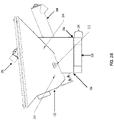
- FIG. 7 is a schematic diagram of an embodiment of a wet fracturing sand agitation system 700 that includes a bulk storage tank 702 positioned above the surge tank 122.
- the bulk storage tank 702 may be part of fracturing sand storage site 102.
- the bulk storage tank 702 includes one or more vibrator components (not shown in FIG. 7 ) similar to the vibrating components as discussed above for the surge tank 122. Including the vibrator components with the bulk storage tank 702 further assists in reducing the clumping of the wet fracturing sand and liquefying the wet fracturing sand. As shown in FIG.
- the bulk storage tank 702 directly feeds into the surge tank 122 using gravity.
- a spout 704 such as a rubber boot, funnels the wet fracturing sand into the top opening of the surge tank 122.
- a prime mover 706 e.g., an electric motor drives the metering system 204 to meter the liquefied wet fracturing sand into one or more blending modules.
- FIG. 2 illustrates a top-down view of an embodiment of a surge tank 122 that comprises a plurality of vibrating components 202.
- two surge tanks 122 are mounted side-by-side to provide fracturing sand to a dual configuration blender as described in more detail in the '114 Patent and U.S. Patent No. 9,534,473, filed December 16, 2015 by Jeffrey G. Morris et al. and entitled "Mobile Electric Power Generation for Hydraulic Fracturing of Subsurface Geological Formations,” (the '473 Patent) which is also incorporated by reference in its entirety.
- a single surge tank 122 or more than two surge tanks 122 may be used to provide fracturing sand to other types of blender modules (e.g., a single surge tank 122 providing fracturing sand to a conventional diesel blender module).
- vibrating components 202 may be mounted at one or more locations of the surge tank 122 to generate mechanical vibration forces that agitate the surge tank 122.
- the vibrating components 202 are mounted on top or affixed to an outer top surface of the surge tank 122.
- the vibrating components 202 are mounted or affixed above the opening where fracturing sand enters surge tank 122.
- the vibrating components 202 generate vibration forces aimed to break bonds between water and fracturing sand particles.
- Other embodiments of the surge tanks 122 may include vibrating components 202 placed at other locations of the surge tank, such as the side walls and/or bottom of the surge tank 122.
- Each of the vibrating components 202 may be configured to generate mechanical forces that shake at least a portion of the surge tank 122 and/or the wet sand independently at relatively high frequencies.
- each of the vibrating components 202 may comprise one or more, electric motors (e.g. an electromagnetic motor), mechanical, pneumatic, and/or hydraulic means that move a set of weights to provide the mechanical vibration force to agitate the surge tank 122.
- Each of the surge tanks 122 may comprise one or more metering systems 204 that meter the wet fracturing sand into one or more blender modules (e.g., a blending tub). As shown in FIG. 2 , the metering systems 204 are coupled to the bottom of each of the surge tanks 122. In FIG. 2 , the metering systems 204 are augers that are positioned at an incline to meter the liquefied wet fracturing sand to the blender modules. In other embodiments of the surge tanks 122, the metering systems 204 may be positioned in a straight or horizontal orientation.
- Correctly controlling and metering the liquefied wet fracturing sand into the blender modules affects the overall proppant concentration of the fracturing fluid (e.g., weight of the slurry). Controlling the overall proppant concentration is advantageous because the overall proppant concentration could affect the proppant transport and the propped fracture dimensions of the subsurface geological formations and the realization of the hydraulic fracturing treatment.
- FIG. 3A illustrate a side view of an embodiment of a surge tank 122 that comprises vibrating components 202 and a vibration isolation system 304.
- the vibration isolation system 304 comprises a vibration isolator 306 and a structure base 308.
- the vibration isolator 306 is a vibration damping spring that prevents other fracturing equipment (e.g., drives, motors, and pumps) located on the same transport from being affected by the vibration.
- Other embodiments of the vibration isolation system 304 may use and/or include other types of vibration isolators 306, such as air bags, rubber-based dampeners and any combination thereof.
- the structure base 308 acts as a platform used to support the surge tank 300 and the vibration isolators 306.
- FIG. 3A illustrates that the surge tanks 122 comprises a spray system configured to provide water to maintain and/or adjust the moisture content of the wet fracturing sand.
- the spray system includes a spray bar 310 at the top of the surge tank 122 and/or near the opening of where a conveyor transfers the fracturing sand to the surge tank 122.
- the spray bar 310 applies liquid, such as water, friction reducers, fracturing fluid, and/or other chemical and additives used to produce fracturing fluid, to moisturize the wet fracturing sand held within the surge tank 122.
- the spray bar 310 can also provide the benefit of reducing the amount of silica dust released into the surrounding air and environment; thereby, reducing the risk of personal injury or death from the inhalation of silica dust.
- the surge tank 122 includes perforated/jet spray piping (not shown in FIG. 3A ) located within a surge tank 122 container that targets and moistures fracturing sand located in different areas of the surge tank 122.
- the perforated/jet spray piping may be capable of providing liquid content, such as spraying the liquid, within the surge tank 122.
- the spray bar 310 and/or perforated/jet spray piping may generate a pre-determined depth of liquid within the surge tank 122 to liquefy the wet fracturing sand.
- the spray system may also be adapted to spray air to assist in liquefying the wet fracturing sand.
- FIG. 3B illustrates a side view of another embodiment of a surge tank 122 that comprises vibrating component 312 and water/air inlet 314.
- FIG. 3B illustrates that the surge tank 122 includes a vibration component 312, such as a pneumatic vibrator or piston vibrator, located near the metering system 204 (e.g., auger).
- the vibration component 312 is affixed to the outer surfaces of the surge tank 122 and is located near or proximate to the metering system 204.
- FIG. 3B illustrates that the vibrating components 312 located at the bottom and/or proximate to the metering system 204 work in conjunction with vibrating components 202 affixed to the top of the surge tank 122
- other embodiments of the surge tank 122 may include the vibrating components 312 near the metering system 204 without using the vibrating components 202 located at the top of the surge tank 122.
- the water/air inlet 314 is an inlet that supplies water and/or air to the spray bar 310 as shown in FIG. 3A and/or the perforated/jet spray piping located within the surge tank 122.
- FIG. 4A illustrates a top-down view of an embodiment of a surge tank 122 that comprises an internal vibrating component 402.
- FIG. 4A illustrates that in addition to including vibrating components 202 located at the top of the surge tank 122, one or more internal vibrating components 402 may be located within the within the surge tank 122 that independently vibrate the fracturing sand without vibrating the surge tank 122.
- the internal vibrating component 402 may include a vibrating screen affixed within the surge tank 122 such that when wet fracturing sand passes through the vibrating screen, the mechanical vibration forces break apart the bonds to liquefy the sand.
- the surge tank 122 may also include a vibration isolation system (e.g., rubber-based dampers) that isolate and prevent transferring of mechanical vibration forces generated from the internal vibrating component 402 to the surge tank 122.
- a vibration isolation system e.g., rubber-based dampers
- one or more vibrating components may each include a vibrating screen that is placed over the surface and at the entrance of the surge tank 122. This way, the vibrating component will assist in liquefying wet fracturing sand prior to entering the surge tank 122.
- the internal vibrating components 402 may be configured to generate and project sound waves (e.g., frequency can vary being subsonic, sonic or ultrasonic waves) into the wet fracturing sand collected within the surge tanks 122. As the sound waves travel through the wet fracturing sand, the sound waves vibrate and break apart bonds between water and/or the fracturing sand particles.
- the internal vibrating components 402 could be placed in a grid-like or an array arrangement where each of the vibrating components 402 target one or more portions of the wet fracturing sand collected within the surge tank 122.
- the frequency and amplitude generated by the internal vibrating components 402 to liquefy sand may depend on a variety of factors that include, but are not limited to the moisture content level, sand particle size, and/or sand particle density.
- the frequency of the internal vibrating components 402 may be cycled and/or implemented in-phase or out-phase to generate the appropriate sound waves.
- FIG. 4B illustrates a side view of an embodiment of a surge tank 122 that includes an internal vibrating component 402 and surge tank isolation components 404.
- the internal vibrating component 402 is positioned between the opening of the surge tank 122 and the metering system 204.
- the top of the surge tank 122 includes surge tank isolation components 404 that dampen vibration generated from the internal vibrating components 402.
- the surge tank isolation components 404 may be used in conjunction with the vibration isolation system 304 as described in FIG. 3B to dampen and isolate vibration forces.
- FIG. 4B also illustrates that the surge tank 122 includes a perforated/jet spray piping 406 regulate the moisture content of the wet fracturing sand.
- the perforated/jet spray piping 406 is located within the surge tank 122 to target and provide moisture to different areas of the surge tank 122.
- the perforated/jet spray piping may be capable of providing liquid content, such as spraying the liquid, within the surge tank 122.
- the spray bar 310 and/or perforated/jet spray piping 406 may generate a pre-determined depth of liquid within the surge tank 122 to liquefy the wet fracturing sand.
- Both the spray bar 310 and perforated/j et spray piping 406 may also be adapted to spray air to assist in liquefying the wet fracturing sand.
- FIG. 4B illustrates that the surge tank 122 includes both the spray bar 310 and perforated/jet spray piping 406, other embodiments of the surge tank 122 can include the perforated/jet spray piping 406 without the spray bar 310 or vice-versa.
- FIGS. 5A and 5B are schematic diagrams of an embodiment of a mobile conveyor system 500 adapted to allow fracture sand transports to drive up to and directly load fracturing sand onto the mobile conveyor system 500.
- FIG. 5A provides a top down view of the mobile conveyor system 500
- FIG. 5B provides a side view of the mobile conveyor system 500.
- the mobile conveyor system 500 includes conveyor ramps/walls 506 that can be positioned in different orientations depending on the operation modes. In transportation mode, the conveyor ramps/walls 506 may be moved to and fastened at a substantially vertical position.
- the conveyor ramps/walls 506 are laid down flat so that fracture sand transports are able to drive up to the mobile conveyor system 500 and load the fracturing sand onto the mobile conveyor system's 500 platform.
- the conveyor ramps/walls 506 may be configured at an angled position (e.g., at an angle less than the vertical position) and vibrate to move sand onto to the mobile conveyor system's 500 platform.
- the mobile conveyor system's 500 platform includes a hopper 504 that funnels the fracturing sand to the conveyor transport component 502 (e.g., a conveyor belt, augers, etc.).
- the conveyor transport component 502 then moves the fracturing sand to a conveyor assembly 508, which then transports the fracturing sand to a surge tank.
- one or more portions of the conveyor assembly 508 may be adapted to disconnect and move to a side-by-side position in transportation mode, and then subsequently connect and move to an extended position in operation mode.
- trailer connection component 510 may be detachable and/or configured to dropped to a lower vertical position so that fracturing sand transports are able to drive up and load the fracturing sand onto the mobile conveyor system's 500 platform during sand transferring operation mode.
- FIG. 6 is a flow chart of an embodiment of a method 600 to provide and utilize wet fracturing sand for hydraulic fracturing.
- Method 600 may start at block 602 by delivering wet fracturing sand received from a processing plant to a well site.
- method 600 may deliver the wet fracturing sand without using specialized transport (e.g., dry bulk tank trailers) or transportation containers designed to prevent exposure of rain, moisture, and/or other environmental factors that could impact the dryness level of the fracturing sand.
- transport e.g., dry bulk tank trailers
- transportation containers designed to prevent exposure of rain, moisture, and/or other environmental factors that could impact the dryness level of the fracturing sand.
- method 600 may use uncovered containers and conventional dump trucks with an open-box bed.
- Method 600 may then move to block 604 and store the wet fracturing sand at and/or near the well site.
- method 600 may store the fracturing sand without using specialized storage facilities and/or containers (e.g., storage silos) that maintain dryness of the fracturing sand.
- specialized storage facilities and/or containers e.g., storage silos
- method 600 may use a liquid spray system to maintain a pre-determined moisture level range for the wet fracturing sand.
- Method 600 continues to block 606 and delivers the wet fracturing sand from the storage site to one or more surge tanks.
- method 600 may transport the wet fracturing sand using mechanical means (e.g. front end loaders and/or conveyor systems).
- the conveyor system may be used to provide a steady and consistent flow of the wet fracturing sand into the surge tanks.
- method 600 moves to block 608 and liquefies the wet fracturing sand within the surge tanks.
- method 600 liquefies the wet fracturing sand by using a plurality of vibration components that reduce clumping of the wet fracturing sand by breaking bonds (e.g., cohesion bonds) between water and the fracturing sand particles.
- the method 600 liquefies the wet fracturing sand by generating and projecting sound waves (e.g., frequency can vary being subsonic, sonic or ultrasonic waves) into the wet fracturing sand collected within the surge tanks to break apart bonds between water and/or the fracturing sand particles.
- sound waves e.g., frequency can vary being subsonic, sonic or ultrasonic waves
- Method 600 then moves to block 610 and meters the liquefied sand to a blender module for mixing proppants with fluid to generate fracturing fluid.
- Method 600 may meter and control the amount of liquefied sand using a metering system (e.g., one or more augers).
Landscapes
- Engineering & Computer Science (AREA)
- Chemical & Material Sciences (AREA)
- Physics & Mathematics (AREA)
- General Engineering & Computer Science (AREA)
- General Physics & Mathematics (AREA)
- Mechanical Engineering (AREA)
- Automation & Control Theory (AREA)
- Chemical Kinetics & Catalysis (AREA)
- Combustion & Propulsion (AREA)
- Dispersion Chemistry (AREA)
- Thermal Sciences (AREA)
- General Health & Medical Sciences (AREA)
- Fluid Mechanics (AREA)
- Analytical Chemistry (AREA)
- Biochemistry (AREA)
- Health & Medical Sciences (AREA)
- Immunology (AREA)
- Pathology (AREA)
- Life Sciences & Earth Sciences (AREA)
- Remote Sensing (AREA)
- Jigging Conveyors (AREA)
- Aerodynamic Tests, Hydrodynamic Tests, Wind Tunnels, And Water Tanks (AREA)
- Underground Or Underwater Handling Of Building Materials (AREA)
- Overhead Projectors And Projection Screens (AREA)
- Jet Pumps And Other Pumps (AREA)
Description
- Hydraulic fracturing has been commonly used by the oil and gas industry to stimulate production of hydrocarbon producing wells, such as oil and/or gas wells. Hydraulic fracturing, sometimes called "fracing" or "fracking" is a process of injecting fracturing fluid, which is typically a mixture of water, proppants (e.g., sand, fracturing sand, ceramics and resin coated materials), and chemicals, into the wellbore to fracture the subsurface geological formations and release hydrocarbon reserves. The fracturing fluid is pumped into a wellbore at a sufficient pressure to cause fissures within the underground geological formations. Once inside the wellbore, the pressurized fracturing fluid flows into the subsurface geological formation to fracture the underground formation. The fracturing fluid may include water, various chemical additives, and proppants that promote the extraction of the hydrocarbon reserves, such as oil and/or gas. Proppants, such as fracturing sand, prevent fissures and fractures in the underground formation from closing, and for the formation to remain open so that hydrocarbon reserves are able to flow to the surface.
- Hydraulic fracturing generally uses large amounts of sand (e.g., about five to fifty million pounds per well) to aid in the fracturing of wells. Prior to transport to the well site, the sand undergoes processing to: (1) remove impurities, (2) to dry the fracturing sand in order for it to meet American Petroleum Institute (API) recommended practices (i.e., RP 19C, 56, 58, and 60) and (3) to make it suitable for metering into the mixing process using conventionally employed hydraulic fracturing process equipment (e.g., fracturing blender) to produce a slurry or fracturing fluid. Mining and/or processing operators initially mine for fracturing sand within sand deposits that contain quartz grains with desired properties, such as relatively high crush strength and roundness. To satisfy fracturing criteria, the operators process the mined sand by washing it to remove impurities and subsequently drying the sand to remove moisture. Mining operators may then further filter out sand particles that fail to satisfy specific size criteria for fracturing operations. Once processing is complete, operators load and deliver the fracturing sand to well sites that may be hundreds of miles from the point of origin using specialized rail cars, trailers (e.g., hopper trailers and pneumatic vessels), and trucks that protect fracturing sand from environmental exposure. Operators use silos, domes, and other large and expensive storage vessels to store the dry sand at various points along the supply chain. Maintaining dry fracturing sand prior to mixing to form fracturing fluid increases an operator's ability to reliably control and meter the flow of fracturing sand. In contrast, wet fracturing sand normally clumps together causing its flow to be less consistent and more difficult to meter for fracturing purposes. Unfortunately, drying, transporting, and storing vast quantities of dry fracturing sand increases financial, operating, and logistical costs associated with fracturing operations.
US 2004/042335 A1 discloses an apparatus and method for introducing a dry material into a fluid stream in a way that ensures a predictable and consistent application of the material where the fluid stream may be fixed or variable, where the material is handled and metered in dry bulk form and may be highly soluble or nearly insoluble, and in a manner that continuously and automatically adjusts the application rate to compensate for varying material bulk density, as well as, and in addition to, varying fluid flow rates or chemical composition, in order to provide a precise fluid treatment level at all times. The invention incorporates the necessary means to store large quantities of the dry process amendment as an integrated and dust-free function of the apparatus and process, and is capable of monitoring and adjusting material levels and introduction rates in real time in response to variations in density, fluid flow rate and/or chemistry composition.
CN 105363362 A teaches an agitator tank and especially relates to a shock-resistant color mixer agitator tank. The shock-resistant color mixer agitator tank comprises an agitator tank body and an agitator motor. The agitator tank body is provided with supporting legs. The supporting leg comprises an upper section and a lower section, a damper spring for supporting the upper section is arranged in the lower section, the upper section is provided with a connection ring, an inner ring goes through the connection ring, the inner ring is connected to the connection ring by a rubber ring, a connection pin goes through the inner ring, and the upper section is connected to the agitator tank body by the connection pin.
US 2015/240148 A1 discloses a device with a substantially continuous stream of aqueous fluid and a substantially continuous stream of gel having a first concentration are combined to form a substantially continuous stream of gel having a second concentration. The second concentration is substantially lower than the first concentration. The gel having the second concentration may thereafter be utilized in conjunction with a well fracturing operation. - The following presents a simplified summary of the disclosed subject matter in order to provide a basic understanding of some aspects of the subject matter disclosed herein. This summary is not an exhaustive overview of the technology disclosed herein. It is not intended to identify key or critical elements of the invention or to delineate the scope of the invention. Its sole purpose is to present some concepts in a simplified form as a prelude to the more detailed description that is discussed later.
- In a described example, a system for utilizing wet fracturing sand for creating fracturing fluid, comprising: a surge tank mounted on a transport and configured to receive wet fracturing sand; a spray component disposed with the surge tank and configured to output a fluid to regulate moisture content of the wet fracturing sand in the surge tank; a vibration component disposed with the surge tank and configured to liquefy the wet fracturing sand received by the surge tank; and a metering system coupled to the surge tank and mounted on the transport, wherein the metering system is configured to: receive the liquefied wet fracturing sand from the surge tank; and control an amount of the liquefied wet fracturing sand output to a blending tub that produces a fracturing fluid.
- In another described example, a method for utilizing wet fracturing sand for fracturing fluid, the method comprising: receiving wet fracturing sand at a surge tank mounted on a transport; spraying a fluid from a spray component disposed with the surge tank to regulate moisture content of the wet fracturing sand received in the surge tank; vibrating the wet fracturing sand located within the surge tank; liquefying the wet fracturing sand within the surge tank based on the vibration; and metering, with a metering system mounted on the transport, the liquefied wet fracturing sand from the surge tank to a blending tub.
- In yet another described example, a surge tank for utilizing wet fracturing sand for fracturing fluid, the surge tank comprising: a spray component disposed with the surge tank and configured to output a fluid to regulate moisture content of wet fracturing sand received in the surge tank, wherein the surge tank is mounted on a transport; a vibration component affixed to an outer surface of the surge tank to cause vibration of the wet fracturing sand that enters the surge tank to liquefy the wet fracturing sand; and an auger coupled to the surge tank and disposed on the transport, wherein the auger is configured to: receive the liquefied wet fracturing sand from the surge tank; and meter an amount of the liquefied wet fracturing sand that is output into a blending tub that produces a fracturing fluid.
- For a more complete understanding of this disclosure, reference is now made to the following brief description, taken in connection with the accompanying drawings and detailed description, wherein like reference numerals represent like parts.
-
FIG. 1 is a schematic diagram of an embodiment of a well site that includes a wet fracturing sand agitation system capable of moving and liquefying wet fracturing sand utilized for producing fracturing fluid. -
FIG. 2 illustrates a top-down view of an embodiment of a surge tank that comprises a plurality of vibrating components. -
FIG. 3A illustrates a side view of an embodiment of a surge tank that comprises a plurality of vibrating components and a vibration isolation system. -
FIG. 3B illustrates a side view of an embodiment of a surge tank that comprises a plurality of vibrating components and a vibration isolation system. -
FIG. 4A illustrates a top-down view of an embodiment of a surge tank that comprises an internal vibrating component. -
FIG. 4B illustrates a side view of an embodiment of a surge tank that includes an internal vibrating component and vibration isolation system. -
FIG. 5A illustrates a top-down view of an embodiment of a mobile conveyor system adapted to allow fracture sand transports to drive up to and directly load fracturing sand onto the mobile conveyor system. -
FIG. 5B illustrates a side view of an embodiment of a mobile conveyor system adapted to allow fracture sand transports to drive up to and directly load fracturing sand onto the mobile conveyor system. -
FIG. 6 is a flow chart of an embodiment of a method to provide and utilize wet fracturing sand for hydraulic fracturing. -
FIG. 7 is a schematic diagram of an embodiment of a wet fracturing sand agitation system that includes a bulk storage tank positioned above the surge tank. - While certain embodiments will be described in connection with the illustrative embodiments shown herein, the invention is not limited to those embodiments. On the contrary, all alternatives, modifications, and equivalents are included within the spirit and scope of the invention as defined by the claims. In the drawing figures, which are not to scale, the same reference numerals are used throughout the description and in the drawing figures for components and elements having the same structure, and primed reference numerals are used for components and elements having a similar function and construction to those components and elements having the same unprimed reference numerals.
- In the following description, for purposes of explanation, numerous specific details are set forth in order to provide a thorough understanding of the invention. It will be apparent, however, to one skilled in the art that the invention may be practiced without these specific details. In other instances, structure and devices are shown in block diagram form in order to avoid obscuring the invention. References to numbers without subscripts or suffixes are understood to reference all instance of subscripts and suffixes corresponding to the referenced number. Moreover, the language used in this disclosure has been principally selected for readability and instructional purposes, and may not have been selected to delineate or circumscribe the inventive subject matter, resort to the claims being necessary to determine such inventive subject matter. Reference in the specification to "one embodiment" or to "an embodiment" means that a particular feature, structure, or characteristic described in connection with the embodiments is included in at least one embodiment of the invention, and multiple references to "one embodiment" or "an embodiment" should not be understood as necessarily all referring to the same embodiment.
- The terms "a," "an," and "the" are not intended to refer to a singular entity unless explicitly so defined, but include the general class of which a specific example may be used for illustration. The use of the terms "a" or "an" may therefore mean any number that is at least one, including "one," "one or more," "at least one," and "one or more than one." The term "or" means any of the alternatives and any combination of the alternatives, including all of the alternatives, unless the alternatives are explicitly indicated as mutually exclusive. The phrase "at least one of' when combined with a list of items, means a single item from the list or any combination of items in the list. The phrase does not require all of the listed items unless explicitly so defined.
- The term "fracturing sand," as used within this disclosure, serves as a non-limiting example of a proppant used as a component of fracturing fluid. "Fracturing sand" is also used herein to collectively refer to both wet and dry fracturing sand. Embodiments in this disclosure are not limited to fracturing sand and any other type of proppant, such as man-made ceramics, aluminum beads and sintered bauxite, can be used with the various embodiments presented in the disclosure. Unless otherwise specified within the disclosure, the term "fracturing sand" can be interchanged with and considered synonymous throughout this disclosure with the term "proppants."
- As used herein, the term "wet fracturing sand" refers to a quantity of fracturing sand that contains a moisture content of about one percent or more, which is typically determined based on weight. The term "dry fracturing sand" refers to quantities of fracturing sand that contain a moisture content of less than about one percent.
- As used herein, the term "liquefying wet fracturing sand" refers to enhancing and transforming the flow properties of wet fracturing sand to be substantially similar to dry fracturing sand in order to accurately control the amount of metered fracturing sand. For example, wet fracturing sand can liquefy and have flow properties similar to dry fracturing sand with the assistance of mechanical forces and/or sound waves.
- As used herein, the term "transport" refers to any transportation assembly, including, but not limited to, a trailer, truck, skid, rail car, and/or barge used to transport relatively heavy structures and/or other types of articles, such as fracturing equipment and fracturing sand.
- As used herein, the term "trailer" refers to a transportation assembly used to transport relatively heavy structures and/or other types of articles, such as fracturing equipment and fracturing sand that can be attached and/or detached from a transportation vehicle used to pull or move the trailer. In one embodiment, the trailer may include mounts and manifold systems to connect the trailer to other fracturing equipment within a fracturing system or fleet.
- Unless otherwise specified within the disclosure, the term "surge tank" can be interchanged with and considered synonymous throughout this disclosure to the term "hopper."
- Various example embodiments are disclosed herein that deliver and/or utilize wet fracturing sand for fracturing operations at one or more well sites. Rather than drying and/or transporting dry fracturing sand to a well site for fracturing operations, fracturing sand may be transported to a well site for fracturing operators without using specialized transport (e.g., dry bulk tank trailers) or transportation containers designed to prevent exposure to rain, moisture, and/or other environmental factors that impact the dryness level of the fracturing sand. Once the transports deliver the fracturing sand to the well site, well-site operators are able to store the fracturing sand without using specialized storage facilities and/or containers (e.g., storage silos) that maintain the relatively low moisture levels required in dry fracturing sand. To produce the fracturing fluid at the well site, the fracturing sand may be moved from a storage site using one or more mechanical means (e.g. front end loaders) that provide the fracturing sand to a conveyor system. The conveyor system subsequently delivers the fracturing sand to a surge tank (e.g., a blender hopper). To process fracturing sand with varying moisture content levels, the surge tank comprises a plurality of vibration components that are adapted to break bonds (e.g., cohesive bonds) created from the surface tension of water that affix particles in fracturing sand together. In one embodiment, the vibration components provide mechanical vibration forces that directly agitate the wet/dry fracturing sand. Additionally, or alternatively, the vibration components provide mechanical vibration forces that agitate the surge tank assembly containing the fracturing sand. In another embodiment, the vibration component generates sound waves that traverse the surge tank to separate fracturing sand particles. Once separated, a metering system (e.g., one or more augers) may control and meter the fracturing sand into a blending module (e.g., a blender tub) to produce fracturing fluid.
-
FIG. 1 is a schematic diagram of an embodiment of awell site 100 that includes a wet fracturing sand agitation system capable of moving and liquefying wet fracturing sand for mixing with fracturing fluid. Thewell site 100 comprises one or more well heads (not illustrated inFIG. 1 ) that the wet fracturing sand agitation system is setup as a component, portion, and/or subsystem of a fracturing system. Initially, to produce fracturing fluid for fracturing the wells, vendors transport proppants, such as fracturing sand, to thewell site 100 using a variety of transportation methods, such as trucks, trailers, rail cars, and/or shipping vessels. In one embodiment, the fracturing sand is delivered to the well site as wet fracturing sand without using specialized containers and/or equipment to maintain a designated moisture level for a dry bulk load. By doing so, operators may be able to reduce product, transportation, and/or storage costs associated with delivering dry fracturing sand to a well site for fracturing operations. Although the wet fracturing sand agitation system used inFIG. 1 is capable of mixing wet fracturing sand with fracturing fluid, the wet fracturing sand agitation system is not limited to using wet fracturing sand and could be compatible with processing dry fracturing sand. - The
well site 100 may include one or more fracturingsand storage sites 102. Transports 104 (e.g., a conventional dump truck) may move fracturing sand from offsite and/or other onsite locations to the fracturingsand storage sites 102. In one embodiment, to reduce well site costs, the fracturingsand storage sites 102 do not include enclosed boxes, containers, storage silos, and/or other storage systems (e.g., fracturing sand storage trailers) designed to prevent exposing dry bulk loads (e.g., dry fracturing sand) to moisture. Instead, the fracturingsand storage sites 102 include uncovered containers and/or uncovered piles of fracturing sand. Additionally, or alternatively, rather than vacuuming or using other means to prevent the release of silica dust caused from storing and handling the fracturing sand, operators may use a liquid spray system to maintain a pre-determined moisture level range for wet fracturing sand stored at the fracturingsand storage sites 102. Introducing moisture into fracturing sand to bind the sand particles together could reduce/prevent the release of silica dust into the air while reducing operating costs. - Operators may move fracturing sand from the fracturing
sand storage sites 102 onto aconveyor system 106 using one or morefront end loaders 116,other transports 104, and/or other mechanical means known by persons of ordinary skill in the art. Theconveyor system 106 is adapted to receive the fracturing sand and move the fracturing sand to thesurge tank 122. Theconveyor systems 106 may include a variety of transloading equipment, such as conveyor belts, conveyor loaders, augers, bucket systems, screw conveyors and/or pneumatic conveyors powered by diesel/gas engines, other mechanical means, and/or electrical means known by persons of ordinary skill in the art. Theconveyor system 106 may be adapted to deliver fracturing sand at a predetermined rate to thesurge tank 122. The amount of fracturing sand theconveyor system 106 delivers to the surge tank may fall within a tolerance range since thesurge tank 122 is capable of handling surges or degrees of variance on the amount of input fracturing sand. For example,conveyor system 106 could be adapted to deliver up to about 20,000 pounds (lbs) of sand per minute. The amount of fracturing sand delivered by theconveyor system 106 could depend on the amount of fracturing sand thesurge tank 122 is set to process and/or meter into a blender tub of a fracturing blending module. For example, theconveyor system 106 may be configured to synchronize withsurge tank 122 to deliver enough fracturing sand to compensate for rate change increases or decreases associated with pumping fracturing fluid into a well. In this instance, theconveyor system 106 could compensate for rate change increase by delivering fracturing sand at a rate greater than 20,000 lbs of sand per minute. - In one embodiment, the
conveyor system 106 includes aconveyor storage container 108 that temporarily stores the fracturing sand and assists in transferring fracturing sand to aconveyor assembly 110. To improve mobility of theconveyor storage container 108, the fracturingsand storage container 108 may comprise a plurality of container segments 112 (including pads and sidewalls) that are connected together.FIG. 1 illustrates an embodiment of aconveyor storage container 108 that comprises fourdifferent container segments 108, where three ends of theconveyor storage container 108 are propped up to build side walls.Entrance 114 of theconveyor storage container 108 allows for afront end loader 116 orother transport 104 to enter, move and/or place sand within theconveyor storage container 108. Theconveyor storage container 108 may include aconveyor transport component 118 that moves fracturing sand stored in theconveyor storage container 108 to theconveyor assembly 110. Theconveyor storage container 108 andconveyor assembly 110 may be connected via aconnection well 120. Theconveyor assembly 110 may then transport the fracturing sand to thesurge tank 122. Other embodiments of theconveyor system 106 may use differentconveyor storage containers 108 and/orconveyor assembly 110 to move and transfer fracturing sand, for example, the mobile conveyor system 500 as described inFIGS. 5A and5B . - When the fracturing sand reaches the
surge tank 122, thesurge tank 122 reduces clumping of the wet fracturing sand by breaking bonds (e.g., cohesion bonds) between water and the fracturing sand particles. Thesurge tank 122 can be configured to break the bonds using one or more vibrator components to liquefy the wet fracturing sand and reduce sand clumping. Thesurge tank 122 may receive from theconveyor system 106 wet fracturing sand that is relatively difficult to meter and control when directly supplying the fracturing sand to a hydraulic fracturing blender tub. By using vibrator components to liquefy the sand, thesurge tank 122 is able to enhance the flow properties of wet fracturing sand in order to accurately control the amount of metered fracturing sand. - In one embodiment, the vibrator components directly vibrate and screen the wet fracturing sand while minimizing vibration forces experienced by the
surge tank 122. Additionally, or alternatively, one or more of the vibrator components can be adapted to generate a mechanical shaking force on thesurge tank 122 to break the cohesion bonds of the wet fracturing sand. In another embodiment, the vibrator components are adapted to generate sound waves that cause vibrations within the wet fracturing sand to break the cohesion bonds. Other types of vibration components known to the art may be used as desired, and combinations of different types of vibration components may be used. A metering system, such as an auger, a gate, a venturi, and/or any other metered conveyor known by persons of ordinary skill in the art, may then meter the liquefied fracturing sand into a blending module (e.g., a blender tub). A blending module may then mix the controlled amount of wet fracturing sand with other fluids to generate fracturing fluid. - The vibrator components may be powered by a variety of power sources that include, but are not limited to, air pressure, hydraulics, and/or electricity. Pneumatic and hydraulic vibrators may be controlled by adjusting the air and hydraulic pressures, respectively. In one embodiment, to power the pneumatic and/or hydraulic vibrators, one or more diesel/gas engines and/or other mechanical means may be used as a power source. In other embodiments where the vibrator components are powered by electricity, operators may use electric motors and electric drives (e.g., variable frequency drives) to control the vibration intensity and/or duration of the vibration either directly or indirectly. For example, one or more vibrator components may be powered using hydraulics systems that are powered by one or more electric motors. Specifically, the electric motors are used to power hydraulic pumps to provide the hydraulic pressure used to operate the vibrator components. By controlling the electric motors, an operator is able to indirectly control the one or more vibrator components via the hydraulic pressure. In another example, operators are able to control the one or more vibrator components directly by connecting one or more electric motors to one or more vibrator components. Adjusting the electric motors' attributes, such as frequency, voltage, and/or amperage could vary operation of the vibrator components.
- The
surge tank 122 depicted inFIG. 1 is applicable to any blending operation for mixing and producing fracturing fluid. In particular, thesurge tank 122 may be mounted on conventional blender modules powered by diesel/gas engines, pneumatic, electric blender modules, and/or other well-known hydraulic fracturing blending equipment and/or transports. As a non-limiting example, thesurge tank 122 may be mounted on a dual configuration electric blender that comprises electric motors for the rotating machinery located on a single transport, which is described in more detail inU.S. Patent No. 9,366,114, filed April 6, 2012 by Todd Coli et al. surge tank 122 may be mounted to blending modules that have been modified to incorporate other hydraulic fracturing equipment onto a single transport. For example,surge tank 122 may be a mounted on a trailer configured to combine a blender unit with a hydration unit. In another example, thesurge tank 122 may be mounted on a trailer that combines a blender unit, a hydration unit, and a sand storage unit. Other embodiments of thesurge tank 122 could be a stand-alone unit that is mounted on its own transport or a stationary unit that is built on the well site. - To reduce vibration and disturbances of other fracturing processes, the
surge tank 122 may include a vibration isolation system that include springs, air bags, rubber-based dampeners (e.g., rubber bushings), and/or other vibration isolation components. The vibration isolation system may be configured to reduce the amount vibration experienced by other blender module components that could be mounted on the same transport. For example, if the vibrator components mechanically cause thesurge tank 122 to continuously or periodically vibrate and shake, the vibration isolation system absorbs and dampens the mechanical vibration energy to avoid transfer of mechanical vibration energy that could potentially damage other blender module components, such as the blender tub and manifolds that are also mounted on the same transport. In embodiments where a vibration screen and/or sound waves are used to directly liquefy sand without vibrating thesurge tank 122, the vibration isolation system may dampen and reduce the amount of vibration experienced by thesurge tank 122. Utilizing a vibration isolation system to dampen vibration from a vibration screen is discussed in more detail inFIGS. 4A and4B . - Although
FIG. 1 illustrates that the fracturingsand storage site 102 do not directly deliver fracturing sand to thesurge tank 122, other embodiments of the wet fracturing sand agitation system can have fracturingsand storage sites 102 that include bulk storage tanks, such as silos or bins that allow the fracturing sand to directly feed or convey into thesurge tank 122. The bulk storage tanks within the fracturingsand storage sites 102 may move the fracturing sand via gravity, conveyor belts, bucket elevators, augers, and/or other mechanical means known by persons of ordinary skill in the art to thesurge tank 122. UsingFIG. 1 as an example, rather than have theconveyor system 106 directly supply wet fracturing sand into thesurge tank 122, theconveyor system 106 can supply wet fracturing sand to a fracturingsand storage site 102 that is elevated above thesurge tank 122. In another example, the wet fracturing sand agitation system may not include aseparate conveyor system 106, and instead replaces theseparate conveyor system 106 with a fracturingsand storage site 102 elevated above thesurge tank 122. In both examples, the fracturingsand storage site 102 may use gravity to directly feed into thesurge tank 122. -
FIG. 7 is a schematic diagram of an embodiment of a wet fracturingsand agitation system 700 that includes abulk storage tank 702 positioned above thesurge tank 122. Recall that inFIG. 1 , thebulk storage tank 702 may be part of fracturingsand storage site 102. In one embodiment, thebulk storage tank 702 includes one or more vibrator components (not shown inFIG. 7 ) similar to the vibrating components as discussed above for thesurge tank 122. Including the vibrator components with thebulk storage tank 702 further assists in reducing the clumping of the wet fracturing sand and liquefying the wet fracturing sand. As shown inFIG. 7 , thebulk storage tank 702 directly feeds into thesurge tank 122 using gravity. Aspout 704, such as a rubber boot, funnels the wet fracturing sand into the top opening of thesurge tank 122. As thesurge tank 122 liquefies the wet fracturing sand, a prime mover 706 (e.g., an electric motor) drives themetering system 204 to meter the liquefied wet fracturing sand into one or more blending modules. -
FIG. 2 illustrates a top-down view of an embodiment of asurge tank 122 that comprises a plurality of vibratingcomponents 202. InFIG. 2 , twosurge tanks 122 are mounted side-by-side to provide fracturing sand to a dual configuration blender as described in more detail in the '114 Patent andU.S. Patent No. 9,534,473, filed December 16, 2015 by Jeffrey G. Morris et al. single surge tank 122 or more than twosurge tanks 122 may be used to provide fracturing sand to other types of blender modules (e.g., asingle surge tank 122 providing fracturing sand to a conventional diesel blender module). - For each of the
surge tanks 122, vibratingcomponents 202 may be mounted at one or more locations of thesurge tank 122 to generate mechanical vibration forces that agitate thesurge tank 122. UsingFIG. 2 as an example, the vibratingcomponents 202 are mounted on top or affixed to an outer top surface of thesurge tank 122. InFIG. 2 , the vibratingcomponents 202 are mounted or affixed above the opening where fracturing sand enterssurge tank 122. The vibratingcomponents 202 generate vibration forces aimed to break bonds between water and fracturing sand particles. Other embodiments of thesurge tanks 122 may include vibratingcomponents 202 placed at other locations of the surge tank, such as the side walls and/or bottom of thesurge tank 122. Each of the vibratingcomponents 202 may be configured to generate mechanical forces that shake at least a portion of thesurge tank 122 and/or the wet sand independently at relatively high frequencies. For example, each of the vibratingcomponents 202 may comprise one or more, electric motors (e.g. an electromagnetic motor), mechanical, pneumatic, and/or hydraulic means that move a set of weights to provide the mechanical vibration force to agitate thesurge tank 122. - Each of the
surge tanks 122 may comprise one ormore metering systems 204 that meter the wet fracturing sand into one or more blender modules (e.g., a blending tub). As shown inFIG. 2 , themetering systems 204 are coupled to the bottom of each of thesurge tanks 122. InFIG. 2 , themetering systems 204 are augers that are positioned at an incline to meter the liquefied wet fracturing sand to the blender modules. In other embodiments of thesurge tanks 122, themetering systems 204 may be positioned in a straight or horizontal orientation. Correctly controlling and metering the liquefied wet fracturing sand into the blender modules affects the overall proppant concentration of the fracturing fluid (e.g., weight of the slurry). Controlling the overall proppant concentration is advantageous because the overall proppant concentration could affect the proppant transport and the propped fracture dimensions of the subsurface geological formations and the realization of the hydraulic fracturing treatment. -
FIG. 3A illustrate a side view of an embodiment of asurge tank 122 that comprises vibratingcomponents 202 and avibration isolation system 304. Thevibration isolation system 304 comprises avibration isolator 306 and astructure base 308. As shown inFIG. 3A , thevibration isolator 306 is a vibration damping spring that prevents other fracturing equipment (e.g., drives, motors, and pumps) located on the same transport from being affected by the vibration. Other embodiments of thevibration isolation system 304 may use and/or include other types ofvibration isolators 306, such as air bags, rubber-based dampeners and any combination thereof. Thestructure base 308 acts as a platform used to support the surge tank 300 and thevibration isolators 306. - To regulate the moisture content of the wet fracturing sand,
FIG. 3A illustrates that thesurge tanks 122 comprises a spray system configured to provide water to maintain and/or adjust the moisture content of the wet fracturing sand. In one embodiment, the spray system includes aspray bar 310 at the top of thesurge tank 122 and/or near the opening of where a conveyor transfers the fracturing sand to thesurge tank 122. Thespray bar 310 applies liquid, such as water, friction reducers, fracturing fluid, and/or other chemical and additives used to produce fracturing fluid, to moisturize the wet fracturing sand held within thesurge tank 122. Thespray bar 310 can also provide the benefit of reducing the amount of silica dust released into the surrounding air and environment; thereby, reducing the risk of personal injury or death from the inhalation of silica dust. In another embodiment, in addition or alternative to usingspray bars 310, thesurge tank 122 includes perforated/jet spray piping (not shown inFIG. 3A ) located within asurge tank 122 container that targets and moistures fracturing sand located in different areas of thesurge tank 122. The perforated/jet spray piping may be capable of providing liquid content, such as spraying the liquid, within thesurge tank 122. In addition, thespray bar 310 and/or perforated/jet spray piping may generate a pre-determined depth of liquid within thesurge tank 122 to liquefy the wet fracturing sand. The spray system may also be adapted to spray air to assist in liquefying the wet fracturing sand. -
FIG. 3B illustrates a side view of another embodiment of asurge tank 122 that comprises vibratingcomponent 312 and water/air inlet 314.FIG. 3B illustrates that thesurge tank 122 includes avibration component 312, such as a pneumatic vibrator or piston vibrator, located near the metering system 204 (e.g., auger). Thevibration component 312 is affixed to the outer surfaces of thesurge tank 122 and is located near or proximate to themetering system 204. Affixing thevibration component 312 at the bottom of thesurge tank 122 and proximate to themetering system 204 allows thevibration component 312 to provide mechanical forces that agitate the bottom of thesurge tank 122 prior to the fracturing sand entering themetering system 204. AlthoughFIG. 3B illustrates that the vibratingcomponents 312 located at the bottom and/or proximate to themetering system 204 work in conjunction with vibratingcomponents 202 affixed to the top of thesurge tank 122, other embodiments of thesurge tank 122 may include the vibratingcomponents 312 near themetering system 204 without using the vibratingcomponents 202 located at the top of thesurge tank 122. InFIG. 3B , the water/air inlet 314 is an inlet that supplies water and/or air to thespray bar 310 as shown inFIG. 3A and/or the perforated/jet spray piping located within thesurge tank 122. -
FIG. 4A illustrates a top-down view of an embodiment of asurge tank 122 that comprises an internal vibratingcomponent 402.FIG. 4A illustrates that in addition to including vibratingcomponents 202 located at the top of thesurge tank 122, one or more internal vibratingcomponents 402 may be located within the within thesurge tank 122 that independently vibrate the fracturing sand without vibrating thesurge tank 122. The internal vibratingcomponent 402 may include a vibrating screen affixed within thesurge tank 122 such that when wet fracturing sand passes through the vibrating screen, the mechanical vibration forces break apart the bonds to liquefy the sand. Thesurge tank 122 may also include a vibration isolation system (e.g., rubber-based dampers) that isolate and prevent transferring of mechanical vibration forces generated from the internal vibratingcomponent 402 to thesurge tank 122. In another embodiment, rather than using an internal vibratingcomponent 402 positioned within thesurge tank 122, one or more vibrating components may each include a vibrating screen that is placed over the surface and at the entrance of thesurge tank 122. This way, the vibrating component will assist in liquefying wet fracturing sand prior to entering thesurge tank 122. - In another embodiment, the internal vibrating
components 402 may be configured to generate and project sound waves (e.g., frequency can vary being subsonic, sonic or ultrasonic waves) into the wet fracturing sand collected within thesurge tanks 122. As the sound waves travel through the wet fracturing sand, the sound waves vibrate and break apart bonds between water and/or the fracturing sand particles. In one embodiment, the internal vibratingcomponents 402 could be placed in a grid-like or an array arrangement where each of the vibratingcomponents 402 target one or more portions of the wet fracturing sand collected within thesurge tank 122. The frequency and amplitude generated by the internal vibratingcomponents 402 to liquefy sand may depend on a variety of factors that include, but are not limited to the moisture content level, sand particle size, and/or sand particle density. For example, the frequency of the internal vibratingcomponents 402 may be cycled and/or implemented in-phase or out-phase to generate the appropriate sound waves. -
FIG. 4B illustrates a side view of an embodiment of asurge tank 122 that includes an internal vibratingcomponent 402 and surgetank isolation components 404. As shown inFIG. 4B , the internal vibratingcomponent 402 is positioned between the opening of thesurge tank 122 and themetering system 204. The top of thesurge tank 122 includes surgetank isolation components 404 that dampen vibration generated from the internal vibratingcomponents 402. InFIG. 4B , the surgetank isolation components 404 may be used in conjunction with thevibration isolation system 304 as described inFIG. 3B to dampen and isolate vibration forces. -
FIG. 4B also illustrates that thesurge tank 122 includes a perforated/jet spray piping 406 regulate the moisture content of the wet fracturing sand. The perforated/jet spray piping 406 is located within thesurge tank 122 to target and provide moisture to different areas of thesurge tank 122. Recall that the perforated/jet spray piping may be capable of providing liquid content, such as spraying the liquid, within thesurge tank 122. In some instances, thespray bar 310 and/or perforated/jet spray piping 406 may generate a pre-determined depth of liquid within thesurge tank 122 to liquefy the wet fracturing sand. Both thespray bar 310 and perforated/j etspray piping 406 may also be adapted to spray air to assist in liquefying the wet fracturing sand. AlthoughFIG. 4B illustrates that thesurge tank 122 includes both thespray bar 310 and perforated/jet spray piping 406, other embodiments of thesurge tank 122 can include the perforated/jet spray piping 406 without thespray bar 310 or vice-versa. -
FIGS. 5A and5B are schematic diagrams of an embodiment of a mobile conveyor system 500 adapted to allow fracture sand transports to drive up to and directly load fracturing sand onto the mobile conveyor system 500.FIG. 5A provides a top down view of the mobile conveyor system 500, andFIG. 5B provides a side view of the mobile conveyor system 500. As shown inFIG. 5A , the mobile conveyor system 500 includes conveyor ramps/walls 506 that can be positioned in different orientations depending on the operation modes. In transportation mode, the conveyor ramps/walls 506 may be moved to and fastened at a substantially vertical position. In a sand loading operation mode, the conveyor ramps/walls 506 are laid down flat so that fracture sand transports are able to drive up to the mobile conveyor system 500 and load the fracturing sand onto the mobile conveyor system's 500 platform. In a sand transferring operation mode, the conveyor ramps/walls 506 may be configured at an angled position (e.g., at an angle less than the vertical position) and vibrate to move sand onto to the mobile conveyor system's 500 platform. - During sand transferring operation mode, the mobile conveyor system's 500 platform includes a
hopper 504 that funnels the fracturing sand to the conveyor transport component 502 (e.g., a conveyor belt, augers, etc.). Theconveyor transport component 502 then moves the fracturing sand to aconveyor assembly 508, which then transports the fracturing sand to a surge tank. InFIGS. 5A and5B , one or more portions of theconveyor assembly 508 may be adapted to disconnect and move to a side-by-side position in transportation mode, and then subsequently connect and move to an extended position in operation mode.FIG. 5B also illustrates that thetrailer connection component 510 may be detachable and/or configured to dropped to a lower vertical position so that fracturing sand transports are able to drive up and load the fracturing sand onto the mobile conveyor system's 500 platform during sand transferring operation mode. -
FIG. 6 is a flow chart of an embodiment of amethod 600 to provide and utilize wet fracturing sand for hydraulic fracturing.Method 600 may start atblock 602 by delivering wet fracturing sand received from a processing plant to a well site. In one embodiment,method 600 may deliver the wet fracturing sand without using specialized transport (e.g., dry bulk tank trailers) or transportation containers designed to prevent exposure of rain, moisture, and/or other environmental factors that could impact the dryness level of the fracturing sand. For example,method 600 may use uncovered containers and conventional dump trucks with an open-box bed.Method 600 may then move to block 604 and store the wet fracturing sand at and/or near the well site. Atblock 604,method 600 may store the fracturing sand without using specialized storage facilities and/or containers (e.g., storage silos) that maintain dryness of the fracturing sand. To prevent the generation of silica dust, which the inhalation may lead to chronic personal injury and/or cause disability or death,method 600 may use a liquid spray system to maintain a pre-determined moisture level range for the wet fracturing sand. -
Method 600 continues to block 606 and delivers the wet fracturing sand from the storage site to one or more surge tanks. In one embodiment,method 600 may transport the wet fracturing sand using mechanical means (e.g. front end loaders and/or conveyor systems). The conveyor system may be used to provide a steady and consistent flow of the wet fracturing sand into the surge tanks. Afterwards,method 600 moves to block 608 and liquefies the wet fracturing sand within the surge tanks. In one embodiment,method 600 liquefies the wet fracturing sand by using a plurality of vibration components that reduce clumping of the wet fracturing sand by breaking bonds (e.g., cohesion bonds) between water and the fracturing sand particles. In another embodiment, themethod 600 liquefies the wet fracturing sand by generating and projecting sound waves (e.g., frequency can vary being subsonic, sonic or ultrasonic waves) into the wet fracturing sand collected within the surge tanks to break apart bonds between water and/or the fracturing sand particles.Method 600 then moves to block 610 and meters the liquefied sand to a blender module for mixing proppants with fluid to generate fracturing fluid.Method 600 may meter and control the amount of liquefied sand using a metering system (e.g., one or more augers). - At least one embodiment is disclosed and variations, combinations, and/or modifications of the embodiment(s) and/or features of the embodiment(s) made by a person having ordinary skill in the art are within the scope of the disclosure. Alternative embodiments that result from combining, integrating, and/or omitting features of the embodiments) are also within the scope of the disclosure. Where numerical ranges or limitations are expressly stated, such express ranges or limitations may be understood to include iterative ranges or limitations of like magnitude falling within the expressly stated ranges or limitations (e.g., from about 1 to about 10 includes, 2, 3, 4, etc.; greater than 0.10 includes 0.11, 0.12, 0.13, etc.). The use of the term "about" means ±10% of the subsequent number, unless otherwise stated.
- Use of the term "optionally" with respect to any element of a claim means that the element is required, or alternatively, the element is not required, both alternatives being within the scope of the claim. Use of broader terms such as comprises, includes, and having may be understood to provide support for narrower terms such as consisting of, consisting essentially of, and comprised substantially of. Accordingly, the scope of protection is not limited by the description set out above but is defined by the claims that follow, that scope including all equivalents of the subject matter of the claims. Each and every claim is incorporated as further disclosure into the specification and the claims are embodiment(s) of the present disclosure.
- While several embodiments have been provided in the present disclosure, it should be understood that the disclosed systems and methods might be embodied in many other specific forms without departing from the scope of the present disclosure. The present examples are to be considered as illustrative and not restrictive, and the intention is not to be limited to the details given herein. For example, the various elements or components may be combined or integrated in another system or certain features may be omitted, or not implemented.
- In addition, techniques, systems, subsystems, and methods described and illustrated in the various embodiments as discrete or separate may be combined or integrated with other systems, modules, techniques, or methods without departing from the scope of the present disclosure. Other items shown or discussed as coupled or directly coupled or communicating with each other may be indirectly coupled or communicating through some interface, device, or intermediate component whether electrically, mechanically, or otherwise.
Claims (15)
- A system for utilizing wet fracturing sand for creating fracturing fluid, comprising:a surge tank (122) mounted on a transport and configured to receive wet fracturing sand;a spray component (310) disposed with the surge tank (122) and configured to output a fluid to regulate moisture content of the wet fracturing sand in the surge tank (122);a vibration component (202, 312, 402) disposed with the surge tank (122) and configured to liquefy the wet fracturing sand received by the surge tank (122); anda metering system (204) coupled to the surge tank (122) and mounted on the transport, wherein the metering system (204) is configured to:receive the liquefied wet fracturing sand from the surge tank; andcontrol an amount of the liquefied wet fracturing sand output to a blending tub that produces a fracturing fluid.
- The system of claim 1, further comprising a vibration isolation system (304) coupled to the surge tank (122), wherein the vibration isolation system (304) is configured to dampen mechanical forces generated from the vibration component (312).
- The system of claim 2, wherein the vibration isolation system (304) includes at least one of a spring, an air bag, or a rubber-based dampener.
- The system of claim 1, wherein the vibration component (212, 312) is mounted at a bottom of the surge tank (122) and generates mechanical vibration at the bottom of the surge tank (122).
- The system of claim 1, wherein the vibration component (202, 312, 402) is positioned on the surge tank (122) to vibrate the wet fracturing sand.
- The system of claim 1, further comprising the blending tub, wherein the blending tub is coupled to the metering system (204) and configured to mix the liquefied wet fracturing sand with a liquid to generate the fracturing fluid.
- The system of claim 1, wherein the vibration component (312) includes at least one vibration member (402) that is positioned within the surge tank (122) and that generates sound waves to vibrate the wet fracturing sand.
- The system of claim 1, wherein the vibration component includes at least one vibration member (202) that is mounted on top of the surge tank (122).
- The system of claim 1, wherein the vibration component includes at least one vibration member (402) that is configured to generate sound waves directed within the surge tank (122).
- The system of claim 1, wherein the spray component comprises a spray bar (310) affixed to a top opening of the surge tank (122).
- The system of claim 1, wherein the spray component comprises a spray system that includes a perforated piping located (406) within the surge tank (122), wherein the perforated piping (406) is configured to output liquid, air, or both.
- A method (600) for utilizing wet fracturing sand for creating fracturing fluid, the method comprising:receiving wet fracturing sand at a surge tank (122) mounted on a transport;spraying a fluid from a spray component (310) disposed with the surge tank (122) to regulate moisture content of the wet fracturing sand received in the surge tank (122);vibrating the wet fracturing sand located within the surge tank (122);liquefying the wet fracturing sand within the surge tank (122) based on the vibration; andmetering, with a metering system mounted on the transport, the liquefied wet fracturing sand from the surge tank (122) to a blending tub.
- The method (600) of claim 12, wherein vibrating the wet fracturing sand located within the surge tank (122) comprises mechanically vibrating the surge tank (122) using a vibrating component (202, 312, 402) attached to the surge tank (122).
- A surge tank (122) for utilizing wet fracturing sand for creating fracturing fluid, the surge tank (122) comprising:a spray component (310) disposed with the surge tank (122) and configured to output a fluid to regulate moisture content of wet fracturing sand received in the surge tank (122), wherein the surge tank (122) is mounted on a transport;a vibration component (312) affixed to an outer surface of the surge tank (122) to cause vibration of the wet fracturing sand that enters the surge tank (122) to liquefy the wet fracturing sand; andan auger coupled to the surge tank (122) and disposed on the transport, wherein the auger is configured to:receive the liquefied wet fracturing sand from the surge tank (122); andmeter an amount of the liquefied wet fracturing sand that is output into a blending tub that produces a fracturing fluid.
- The surge tank of claim 14, wherein the spray component comprises a spray bar (310) located at a top opening of the surge tank (122) to introduce air, liquid, or both into the surge tank (122).
Priority Applications (1)
| Application Number | Priority Date | Filing Date | Title |
|---|---|---|---|
| PL17763916T PL3426888T3 (en) | 2016-03-08 | 2017-03-07 | Utilizing wet fracturing sand for hydraulic fracturing operations |
Applications Claiming Priority (2)
| Application Number | Priority Date | Filing Date | Title |
|---|---|---|---|
| US201662305449P | 2016-03-08 | 2016-03-08 | |
| PCT/US2017/021181 WO2017156018A1 (en) | 2016-03-08 | 2017-03-07 | Utilizing wet fracturing sand for hydraulic fracturing operations |
Publications (3)
| Publication Number | Publication Date |
|---|---|
| EP3426888A1 EP3426888A1 (en) | 2019-01-16 |
| EP3426888A4 EP3426888A4 (en) | 2019-11-13 |
| EP3426888B1 true EP3426888B1 (en) | 2021-04-21 |
Family
ID=59787671
Family Applications (1)
| Application Number | Title | Priority Date | Filing Date |
|---|---|---|---|
| EP17763916.8A Active EP3426888B1 (en) | 2016-03-08 | 2017-03-07 | Utilizing wet fracturing sand for hydraulic fracturing operations |
Country Status (9)
| Country | Link |
|---|---|
| US (3) | US10076733B2 (en) |
| EP (1) | EP3426888B1 (en) |
| AR (2) | AR107822A1 (en) |
| AU (1) | AU2017229475B2 (en) |
| BR (1) | BR112018068197B1 (en) |
| CA (1) | CA3016070C (en) |
| MX (2) | MX2018010730A (en) |
| PL (1) | PL3426888T3 (en) |
| WO (1) | WO2017156018A1 (en) |
Cited By (3)
| Publication number | Priority date | Publication date | Assignee | Title |
|---|---|---|---|---|
| US11851998B2 (en) | 2011-04-07 | 2023-12-26 | Typhon Technology Solutions (U.S.), Llc | Dual pump VFD controlled motor electric fracturing system |
| US12444910B2 (en) | 2022-11-01 | 2025-10-14 | Typhon Technology Solutions (U.S.), Llc | Method for accessing electric grids to power fracturing operations |
| US12546198B2 (en) | 2023-10-09 | 2026-02-10 | Typhon Technology Solutions (U.S.), Llc | Multiple generator mobile electric powered fracturing system |
Families Citing this family (59)
| Publication number | Priority date | Publication date | Assignee | Title |
|---|---|---|---|---|
| US9140110B2 (en) | 2012-10-05 | 2015-09-22 | Evolution Well Services, Llc | Mobile, modular, electrically powered system for use in fracturing underground formations using liquid petroleum gas |
| US11255173B2 (en) | 2011-04-07 | 2022-02-22 | Typhon Technology Solutions, Llc | Mobile, modular, electrically powered system for use in fracturing underground formations using liquid petroleum gas |
| US10119381B2 (en) | 2012-11-16 | 2018-11-06 | U.S. Well Services, LLC | System for reducing vibrations in a pressure pumping fleet |
| US9745840B2 (en) | 2012-11-16 | 2017-08-29 | Us Well Services Llc | Electric powered pump down |
| US10407990B2 (en) | 2012-11-16 | 2019-09-10 | U.S. Well Services, LLC | Slide out pump stand for hydraulic fracturing equipment |
| US9970278B2 (en) | 2012-11-16 | 2018-05-15 | U.S. Well Services, LLC | System for centralized monitoring and control of electric powered hydraulic fracturing fleet |
| US10232332B2 (en) | 2012-11-16 | 2019-03-19 | U.S. Well Services, Inc. | Independent control of auger and hopper assembly in electric blender system |
| US10020711B2 (en) | 2012-11-16 | 2018-07-10 | U.S. Well Services, LLC | System for fueling electric powered hydraulic fracturing equipment with multiple fuel sources |
| US10036238B2 (en) | 2012-11-16 | 2018-07-31 | U.S. Well Services, LLC | Cable management of electric powered hydraulic fracturing pump unit |
| US11476781B2 (en) | 2012-11-16 | 2022-10-18 | U.S. Well Services, LLC | Wireline power supply during electric powered fracturing operations |
| US9410410B2 (en) | 2012-11-16 | 2016-08-09 | Us Well Services Llc | System for pumping hydraulic fracturing fluid using electric pumps |
| US10254732B2 (en) | 2012-11-16 | 2019-04-09 | U.S. Well Services, Inc. | Monitoring and control of proppant storage from a datavan |
| US9995218B2 (en) | 2012-11-16 | 2018-06-12 | U.S. Well Services, LLC | Turbine chilling for oil field power generation |
| US9650879B2 (en) | 2012-11-16 | 2017-05-16 | Us Well Services Llc | Torsional coupling for electric hydraulic fracturing fluid pumps |
| US9893500B2 (en) | 2012-11-16 | 2018-02-13 | U.S. Well Services, LLC | Switchgear load sharing for oil field equipment |
| US11449018B2 (en) | 2012-11-16 | 2022-09-20 | U.S. Well Services, LLC | System and method for parallel power and blackout protection for electric powered hydraulic fracturing |
| US9840901B2 (en) | 2012-11-16 | 2017-12-12 | U.S. Well Services, LLC | Remote monitoring for hydraulic fracturing equipment |
| US11959371B2 (en) | 2012-11-16 | 2024-04-16 | Us Well Services, Llc | Suction and discharge lines for a dual hydraulic fracturing unit |
| US10526882B2 (en) | 2012-11-16 | 2020-01-07 | U.S. Well Services, LLC | Modular remote power generation and transmission for hydraulic fracturing system |
| CA2908276C (en) | 2014-10-14 | 2022-11-01 | Us Well Services Llc | Parallel power and blackout protection for electric hydraulic fracturing |
| WO2016100524A1 (en) | 2014-12-19 | 2016-06-23 | Evolution Well Services, Llc | Mobile electric power generation for hydraulic fracturing of subsurface geological formations |
| US10378326B2 (en) | 2014-12-19 | 2019-08-13 | Typhon Technology Solutions, Llc | Mobile fracturing pump transport for hydraulic fracturing of subsurface geological formations |
| US12078110B2 (en) | 2015-11-20 | 2024-09-03 | Us Well Services, Llc | System for gas compression on electric hydraulic fracturing fleets |
| US11181107B2 (en) | 2016-12-02 | 2021-11-23 | U.S. Well Services, LLC | Constant voltage power distribution system for use with an electric hydraulic fracturing system |
| MX390088B (en) | 2017-06-29 | 2025-03-20 | Typhon Tech Solutions Llc | Electric power distribution for fracturing operation |
| US10280724B2 (en) | 2017-07-07 | 2019-05-07 | U.S. Well Services, Inc. | Hydraulic fracturing equipment with non-hydraulic power |
| CA3078509A1 (en) | 2017-10-05 | 2019-04-11 | U.S. Well Services, LLC | Instrumented fracturing slurry flow system and method |
| WO2019075475A1 (en) | 2017-10-13 | 2019-04-18 | U.S. Well Services, LLC | Automatic fracturing system and method |
| US10655435B2 (en) | 2017-10-25 | 2020-05-19 | U.S. Well Services, LLC | Smart fracturing system and method |
| US11643287B2 (en) | 2017-11-14 | 2023-05-09 | Walker-Dawson Interests, Inc. | Systems and methods for conveying a non-dry frac proppant |
| CA3084596A1 (en) | 2017-12-05 | 2019-06-13 | U.S. Well Services, LLC | Multi-plunger pumps and associated drive systems |
| WO2019113153A1 (en) | 2017-12-05 | 2019-06-13 | U.S. Well Services, Inc. | High horsepower pumping configuration for an electric hydraulic fracturing system |
| WO2019136017A1 (en) | 2018-01-02 | 2019-07-11 | Typhon Technology Solutions, Llc | Exhaust heat recovery from mobile power generation system |
| CA3090408A1 (en) | 2018-02-05 | 2019-08-08 | U.S. Well Services, LLC | Microgrid electrical load management |
| AR115054A1 (en) | 2018-04-16 | 2020-11-25 | U S Well Services Inc | HYBRID HYDRAULIC FRACTURING FLEET |
| US11211801B2 (en) | 2018-06-15 | 2021-12-28 | U.S. Well Services, LLC | Integrated mobile power unit for hydraulic fracturing |
| BR112021001805B1 (en) | 2018-08-01 | 2023-01-31 | Typhon Technology Solutions, Llc. | ELECTRICAL FRACTURING SYSTEM, TRANSPORT OF DISTRIBUTION MECHANISM AND METHOD FOR DISTRIBUTING ELECTRIC ENERGY |
| WO2020033181A1 (en) | 2018-08-06 | 2020-02-13 | Typhon Technology Solutions, Llc | Engagement and disengagement with external gear box style pumps |
| WO2020033861A2 (en) * | 2018-08-10 | 2020-02-13 | Matthew Oehler | Proppant dispensing system |
| US10648270B2 (en) | 2018-09-14 | 2020-05-12 | U.S. Well Services, LLC | Riser assist for wellsites |
| WO2020076902A1 (en) | 2018-10-09 | 2020-04-16 | U.S. Well Services, LLC | Modular switchgear system and power distribution for electric oilfield equipment |
| WO2020139630A1 (en) | 2018-12-28 | 2020-07-02 | Typhon Technology Solutions, Llc | Prime mover and lube oil cooling assembly for fracturing pump transport |
| US11578577B2 (en) | 2019-03-20 | 2023-02-14 | U.S. Well Services, LLC | Oversized switchgear trailer for electric hydraulic fracturing |
| EP3963178A4 (en) | 2019-05-01 | 2022-12-14 | Typhon Technology Solutions, LLC | Single-transport mobile electric power generation |
| US11512632B2 (en) | 2019-05-01 | 2022-11-29 | Typhon Technology Solutions (U.S.), Llc | Single-transport mobile electric power generation |
| US11728709B2 (en) | 2019-05-13 | 2023-08-15 | U.S. Well Services, LLC | Encoderless vector control for VFD in hydraulic fracturing applications |
| US11927087B2 (en) | 2019-07-26 | 2024-03-12 | Typhon Technology Solutions (U.S.), Llc | Artificial intelligence based hydraulic fracturing system monitoring and control |
| WO2021022048A1 (en) | 2019-08-01 | 2021-02-04 | U.S. Well Services, LLC | High capacity power storage system for electric hydraulic fracturing |
| US11512683B2 (en) | 2019-10-08 | 2022-11-29 | Typhon Technology Solutions (U.S.), Llc | Chilled intake air for increased power generation |
| US11009162B1 (en) | 2019-12-27 | 2021-05-18 | U.S. Well Services, LLC | System and method for integrated flow supply line |
| US11885206B2 (en) * | 2019-12-30 | 2024-01-30 | U.S. Well Services, LLC | Electric motor driven transportation mechanisms for fracturing blenders |
| US11519252B2 (en) | 2021-05-07 | 2022-12-06 | Halliburton Energy Services, Inc. | Systems and methods for manufacturing and delivering fracturing fluid to multiple wells for conducting fracturing operations |
| US20220363493A1 (en) * | 2021-05-14 | 2022-11-17 | SandSled, LLC | Systems and methods for handling particulate material |
| US11465155B1 (en) | 2021-06-16 | 2022-10-11 | Propflow, Llc | Wellsite wet screening systems for proppants and methods of using same |
| US20240265344A1 (en) * | 2021-08-12 | 2024-08-08 | Schlumberger Technology Corporation | Sand pile completion system and method |
| US12312159B2 (en) | 2021-12-06 | 2025-05-27 | Halliburton Energy Services, Inc. | Bulk material container for well operations system supply and transport |
| US12116224B2 (en) | 2021-12-06 | 2024-10-15 | Halliburton Energy Services, Inc. | Bulk material unloading systems and methods |
| US11725582B1 (en) | 2022-04-28 | 2023-08-15 | Typhon Technology Solutions (U.S.), Llc | Mobile electric power generation system |
| US11913317B2 (en) | 2022-05-05 | 2024-02-27 | Colton Willis | Proppants processing system and method |
Family Cites Families (22)
| Publication number | Priority date | Publication date | Assignee | Title |
|---|---|---|---|---|
| US1753050A (en) * | 1929-04-06 | 1930-04-01 | Robert H S Hughes | Stoker attachment |
| US1907721A (en) * | 1930-03-04 | 1933-05-09 | Wallace & Tiernan Company Inc | Feeding device for solid substances |
| US3113621A (en) | 1960-04-18 | 1963-12-10 | Union Oil Co | Subterranean well treatments using a vibrational field |
| US3147144A (en) * | 1962-05-01 | 1964-09-01 | Rohm & Haas | Apparatus for dusting tacky filaments with powder |
| US3187958A (en) * | 1963-10-14 | 1965-06-08 | Louis D Srybnik | Anti-bridging device for ice cube vending machines |
| US3533605A (en) * | 1968-06-07 | 1970-10-13 | Irl Daffin Associates | Vibrating hopper arrangement |
| US3893655A (en) * | 1972-07-10 | 1975-07-08 | Union Oil Co | Apparatus and method for dispersing solid particles in a liquid |
| US3782695A (en) * | 1972-07-10 | 1974-01-01 | Union Oil Co | Apparatus and method for dispersing solid particles in a liquid |
| US6979116B2 (en) * | 2002-08-30 | 2005-12-27 | Wastewater Solutions, Inc. | Apparatus for injecting dry bulk amendments for water and soil treatment |
| US6953279B2 (en) * | 2003-01-21 | 2005-10-11 | Red Devil Equipment Company | Paint mixer with damping frame |
| US20080264641A1 (en) * | 2007-04-30 | 2008-10-30 | Slabaugh Billy F | Blending Fracturing Gel |
| US8360152B2 (en) * | 2008-10-21 | 2013-01-29 | Encana Corporation | Process and process line for the preparation of hydraulic fracturing fluid |
| US20110073599A1 (en) | 2009-09-29 | 2011-03-31 | Nieves Luis A | Dust control cover for a refuse bin |
| PL3444430T3 (en) | 2011-04-07 | 2021-07-05 | Typhon Technology Solutions, Llc | Electrically powered system for use in fracturing underground formations |
| US20140027386A1 (en) * | 2012-07-27 | 2014-01-30 | MBJ Water Partners | Fracture Water Treatment Method and System |
| US10232332B2 (en) | 2012-11-16 | 2019-03-19 | U.S. Well Services, Inc. | Independent control of auger and hopper assembly in electric blender system |
| US10254732B2 (en) | 2012-11-16 | 2019-04-09 | U.S. Well Services, Inc. | Monitoring and control of proppant storage from a datavan |
| EP2981669A4 (en) * | 2013-03-07 | 2017-02-15 | Prostim Labs, LLC | Fracturing systems and methods for a wellbore |
| US9322595B1 (en) * | 2013-09-18 | 2016-04-26 | Industrial Accessories Company | Method and apparatus for conditioning of fracturing sand |
| US11453146B2 (en) * | 2014-02-27 | 2022-09-27 | Schlumberger Technology Corporation | Hydration systems and methods |
| US20160175793A1 (en) * | 2014-12-18 | 2016-06-23 | General Electric Company | Material transporting devices and systems |
| CN105363362B (en) * | 2015-11-13 | 2018-03-23 | 浙江康成新材料科技有限公司 | Antivibration formula colour mixer agitator tank |
-
2017
- 2017-03-07 US US15/452,415 patent/US10076733B2/en active Active
- 2017-03-07 MX MX2018010730A patent/MX2018010730A/en unknown
- 2017-03-07 BR BR112018068197-0A patent/BR112018068197B1/en active IP Right Grant
- 2017-03-07 AR ARP170100564A patent/AR107822A1/en active IP Right Grant
- 2017-03-07 CA CA3016070A patent/CA3016070C/en active Active
- 2017-03-07 PL PL17763916T patent/PL3426888T3/en unknown
- 2017-03-07 EP EP17763916.8A patent/EP3426888B1/en active Active
- 2017-03-07 WO PCT/US2017/021181 patent/WO2017156018A1/en not_active Ceased
- 2017-03-07 AU AU2017229475A patent/AU2017229475B2/en active Active
-
2018
- 2018-08-07 US US16/056,820 patent/US10518229B2/en not_active Ceased
- 2018-09-05 MX MX2022011944A patent/MX2022011944A/en unknown
-
2021
- 2021-11-15 AR ARP210103157A patent/AR124068A2/en active IP Right Grant
- 2021-11-17 US US17/528,978 patent/USRE50007E1/en active Active
Non-Patent Citations (1)
| Title |
|---|
| None * |
Cited By (3)
| Publication number | Priority date | Publication date | Assignee | Title |
|---|---|---|---|---|
| US11851998B2 (en) | 2011-04-07 | 2023-12-26 | Typhon Technology Solutions (U.S.), Llc | Dual pump VFD controlled motor electric fracturing system |
| US12444910B2 (en) | 2022-11-01 | 2025-10-14 | Typhon Technology Solutions (U.S.), Llc | Method for accessing electric grids to power fracturing operations |
| US12546198B2 (en) | 2023-10-09 | 2026-02-10 | Typhon Technology Solutions (U.S.), Llc | Multiple generator mobile electric powered fracturing system |
Also Published As
| Publication number | Publication date |
|---|---|
| CA3016070C (en) | 2020-08-04 |
| WO2017156018A1 (en) | 2017-09-14 |
| BR112018068197A2 (en) | 2019-01-29 |
| US20180339278A1 (en) | 2018-11-29 |
| CA3016070A1 (en) | 2017-09-14 |
| US10518229B2 (en) | 2019-12-31 |
| AU2017229475A1 (en) | 2018-09-27 |
| MX2022011944A (en) | 2022-10-21 |
| AU2017229475B2 (en) | 2020-02-06 |
| AR124068A2 (en) | 2023-02-08 |
| EP3426888A1 (en) | 2019-01-16 |
| PL3426888T3 (en) | 2021-07-26 |
| US20170259227A1 (en) | 2017-09-14 |
| AR107822A1 (en) | 2018-06-06 |
| USRE50007E1 (en) | 2024-06-11 |
| US10076733B2 (en) | 2018-09-18 |
| MX2018010730A (en) | 2019-06-20 |
| EP3426888A4 (en) | 2019-11-13 |
| BR112018068197B1 (en) | 2022-12-20 |
Similar Documents
| Publication | Publication Date | Title |
|---|---|---|
| USRE50007E1 (en) | Utilizing wet fracturing sand for hydraulic fracturing operations | |
| US11192077B2 (en) | Blender unit with integrated container support frame | |
| CN104271877B (en) | Systems and methods for transporting treatment fluids | |
| US11896983B2 (en) | Wellsite wet screening system for proppants and methods of using same | |
| US10077610B2 (en) | System and method for delivery of oilfield materials | |
| RU2644738C2 (en) | System and method for delivery of oilfield materials | |
| US20150003185A1 (en) | Mobile fracking slurry mixing device | |
| US11186454B2 (en) | Dust control systems for discharge of bulk material | |
| WO2017044921A1 (en) | Dry bulk material transportation | |
| CN120172020A (en) | An operating system for wet fracturing sand well field | |
| CN120081211A (en) | A wet fracturing sand conveying device and an operating system for a wet fracturing sand well site |
Legal Events
| Date | Code | Title | Description |
|---|---|---|---|
| STAA | Information on the status of an ep patent application or granted ep patent |
Free format text: STATUS: THE INTERNATIONAL PUBLICATION HAS BEEN MADE |
|
| PUAI | Public reference made under article 153(3) epc to a published international application that has entered the european phase |
Free format text: ORIGINAL CODE: 0009012 |
|
| STAA | Information on the status of an ep patent application or granted ep patent |
Free format text: STATUS: REQUEST FOR EXAMINATION WAS MADE |
|
| 17P | Request for examination filed |
Effective date: 20181004 |
|
| AK | Designated contracting states |
Kind code of ref document: A1 Designated state(s): AL AT BE BG CH CY CZ DE DK EE ES FI FR GB GR HR HU IE IS IT LI LT LU LV MC MK MT NL NO PL PT RO RS SE SI SK SM TR |
|
| AX | Request for extension of the european patent |
Extension state: BA ME |
|
| RIN1 | Information on inventor provided before grant (corrected) |
Inventor name: JENSEN, NEAL Inventor name: MORRIS, JEFFREY, G. Inventor name: BATEMAN, MICHAEL Inventor name: BODISHBAUGH, ADRIAN, BENJAMIN |
|
| DAV | Request for validation of the european patent (deleted) | ||
| DAX | Request for extension of the european patent (deleted) | ||
| A4 | Supplementary search report drawn up and despatched |
Effective date: 20191016 |
|
| RIC1 | Information provided on ipc code assigned before grant |
Ipc: E21B 43/26 20060101ALI20191010BHEP Ipc: B01F 11/02 20060101ALI20191010BHEP Ipc: C09K 8/80 20060101ALI20191010BHEP Ipc: E21B 21/06 20060101ALI20191010BHEP Ipc: E21B 43/267 20060101AFI20191010BHEP Ipc: B01F 3/12 20060101ALI20191010BHEP |
|
| RAP1 | Party data changed (applicant data changed or rights of an application transferred) |
Owner name: TYPHON TECHNOLOGY SOLUTIONS, LLC |
|
| GRAP | Despatch of communication of intention to grant a patent |
Free format text: ORIGINAL CODE: EPIDOSNIGR1 |
|
| STAA | Information on the status of an ep patent application or granted ep patent |
Free format text: STATUS: GRANT OF PATENT IS INTENDED |
|
| INTG | Intention to grant announced |
Effective date: 20200707 |
|
| GRAJ | Information related to disapproval of communication of intention to grant by the applicant or resumption of examination proceedings by the epo deleted |
Free format text: ORIGINAL CODE: EPIDOSDIGR1 |
|
| STAA | Information on the status of an ep patent application or granted ep patent |
Free format text: STATUS: REQUEST FOR EXAMINATION WAS MADE |
|
| INTC | Intention to grant announced (deleted) | ||
| GRAS | Grant fee paid |
Free format text: ORIGINAL CODE: EPIDOSNIGR3 |
|
| STAA | Information on the status of an ep patent application or granted ep patent |
Free format text: STATUS: GRANT OF PATENT IS INTENDED |
|
| GRAP | Despatch of communication of intention to grant a patent |
Free format text: ORIGINAL CODE: EPIDOSNIGR1 |
|
| GRAA | (expected) grant |
Free format text: ORIGINAL CODE: 0009210 |
|
| STAA | Information on the status of an ep patent application or granted ep patent |
Free format text: STATUS: THE PATENT HAS BEEN GRANTED |
|
| INTG | Intention to grant announced |
Effective date: 20210302 |
|
| AK | Designated contracting states |
Kind code of ref document: B1 Designated state(s): AL AT BE BG CH CY CZ DE DK EE ES FI FR GB GR HR HU IE IS IT LI LT LU LV MC MK MT NL NO PL PT RO RS SE SI SK SM TR |
|
| REG | Reference to a national code |
Ref country code: GB Ref legal event code: FG4D |
|
| REG | Reference to a national code |
Ref country code: CH Ref legal event code: EP |
|
| REG | Reference to a national code |
Ref country code: DE Ref legal event code: R096 Ref document number: 602017037168 Country of ref document: DE |
|
| REG | Reference to a national code |
Ref country code: IE Ref legal event code: FG4D |
|
| REG | Reference to a national code |
Ref country code: AT Ref legal event code: REF Ref document number: 1384817 Country of ref document: AT Kind code of ref document: T Effective date: 20210515 |
|
| REG | Reference to a national code |
Ref country code: LT Ref legal event code: MG9D |
|
| REG | Reference to a national code |
Ref country code: AT Ref legal event code: MK05 Ref document number: 1384817 Country of ref document: AT Kind code of ref document: T Effective date: 20210421 |
|
| REG | Reference to a national code |
Ref country code: NL Ref legal event code: MP Effective date: 20210421 |
|
| PG25 | Lapsed in a contracting state [announced via postgrant information from national office to epo] |
Ref country code: FI Free format text: LAPSE BECAUSE OF FAILURE TO SUBMIT A TRANSLATION OF THE DESCRIPTION OR TO PAY THE FEE WITHIN THE PRESCRIBED TIME-LIMIT Effective date: 20210421 Ref country code: LT Free format text: LAPSE BECAUSE OF FAILURE TO SUBMIT A TRANSLATION OF THE DESCRIPTION OR TO PAY THE FEE WITHIN THE PRESCRIBED TIME-LIMIT Effective date: 20210421 Ref country code: NL Free format text: LAPSE BECAUSE OF FAILURE TO SUBMIT A TRANSLATION OF THE DESCRIPTION OR TO PAY THE FEE WITHIN THE PRESCRIBED TIME-LIMIT Effective date: 20210421 Ref country code: HR Free format text: LAPSE BECAUSE OF FAILURE TO SUBMIT A TRANSLATION OF THE DESCRIPTION OR TO PAY THE FEE WITHIN THE PRESCRIBED TIME-LIMIT Effective date: 20210421 Ref country code: AT Free format text: LAPSE BECAUSE OF FAILURE TO SUBMIT A TRANSLATION OF THE DESCRIPTION OR TO PAY THE FEE WITHIN THE PRESCRIBED TIME-LIMIT Effective date: 20210421 Ref country code: BG Free format text: LAPSE BECAUSE OF FAILURE TO SUBMIT A TRANSLATION OF THE DESCRIPTION OR TO PAY THE FEE WITHIN THE PRESCRIBED TIME-LIMIT Effective date: 20210721 |
|
| PG25 | Lapsed in a contracting state [announced via postgrant information from national office to epo] |
Ref country code: GR Free format text: LAPSE BECAUSE OF FAILURE TO SUBMIT A TRANSLATION OF THE DESCRIPTION OR TO PAY THE FEE WITHIN THE PRESCRIBED TIME-LIMIT Effective date: 20210722 Ref country code: IS Free format text: LAPSE BECAUSE OF FAILURE TO SUBMIT A TRANSLATION OF THE DESCRIPTION OR TO PAY THE FEE WITHIN THE PRESCRIBED TIME-LIMIT Effective date: 20210821 Ref country code: LV Free format text: LAPSE BECAUSE OF FAILURE TO SUBMIT A TRANSLATION OF THE DESCRIPTION OR TO PAY THE FEE WITHIN THE PRESCRIBED TIME-LIMIT Effective date: 20210421 Ref country code: PT Free format text: LAPSE BECAUSE OF FAILURE TO SUBMIT A TRANSLATION OF THE DESCRIPTION OR TO PAY THE FEE WITHIN THE PRESCRIBED TIME-LIMIT Effective date: 20210823 Ref country code: NO Free format text: LAPSE BECAUSE OF FAILURE TO SUBMIT A TRANSLATION OF THE DESCRIPTION OR TO PAY THE FEE WITHIN THE PRESCRIBED TIME-LIMIT Effective date: 20210721 Ref country code: RS Free format text: LAPSE BECAUSE OF FAILURE TO SUBMIT A TRANSLATION OF THE DESCRIPTION OR TO PAY THE FEE WITHIN THE PRESCRIBED TIME-LIMIT Effective date: 20210421 Ref country code: SE Free format text: LAPSE BECAUSE OF FAILURE TO SUBMIT A TRANSLATION OF THE DESCRIPTION OR TO PAY THE FEE WITHIN THE PRESCRIBED TIME-LIMIT Effective date: 20210421 |
|
| REG | Reference to a national code |
Ref country code: DE Ref legal event code: R097 Ref document number: 602017037168 Country of ref document: DE |
|
| PG25 | Lapsed in a contracting state [announced via postgrant information from national office to epo] |
Ref country code: SK Free format text: LAPSE BECAUSE OF FAILURE TO SUBMIT A TRANSLATION OF THE DESCRIPTION OR TO PAY THE FEE WITHIN THE PRESCRIBED TIME-LIMIT Effective date: 20210421 Ref country code: SM Free format text: LAPSE BECAUSE OF FAILURE TO SUBMIT A TRANSLATION OF THE DESCRIPTION OR TO PAY THE FEE WITHIN THE PRESCRIBED TIME-LIMIT Effective date: 20210421 Ref country code: CZ Free format text: LAPSE BECAUSE OF FAILURE TO SUBMIT A TRANSLATION OF THE DESCRIPTION OR TO PAY THE FEE WITHIN THE PRESCRIBED TIME-LIMIT Effective date: 20210421 Ref country code: EE Free format text: LAPSE BECAUSE OF FAILURE TO SUBMIT A TRANSLATION OF THE DESCRIPTION OR TO PAY THE FEE WITHIN THE PRESCRIBED TIME-LIMIT Effective date: 20210421 Ref country code: DK Free format text: LAPSE BECAUSE OF FAILURE TO SUBMIT A TRANSLATION OF THE DESCRIPTION OR TO PAY THE FEE WITHIN THE PRESCRIBED TIME-LIMIT Effective date: 20210421 Ref country code: ES Free format text: LAPSE BECAUSE OF FAILURE TO SUBMIT A TRANSLATION OF THE DESCRIPTION OR TO PAY THE FEE WITHIN THE PRESCRIBED TIME-LIMIT Effective date: 20210421 Ref country code: RO Free format text: LAPSE BECAUSE OF FAILURE TO SUBMIT A TRANSLATION OF THE DESCRIPTION OR TO PAY THE FEE WITHIN THE PRESCRIBED TIME-LIMIT Effective date: 20210421 |
|
| PLBE | No opposition filed within time limit |
Free format text: ORIGINAL CODE: 0009261 |
|
| STAA | Information on the status of an ep patent application or granted ep patent |
Free format text: STATUS: NO OPPOSITION FILED WITHIN TIME LIMIT |
|
| 26N | No opposition filed |
Effective date: 20220124 |
|
| PG25 | Lapsed in a contracting state [announced via postgrant information from national office to epo] |
Ref country code: IS Free format text: LAPSE BECAUSE OF FAILURE TO SUBMIT A TRANSLATION OF THE DESCRIPTION OR TO PAY THE FEE WITHIN THE PRESCRIBED TIME-LIMIT Effective date: 20210821 Ref country code: AL Free format text: LAPSE BECAUSE OF FAILURE TO SUBMIT A TRANSLATION OF THE DESCRIPTION OR TO PAY THE FEE WITHIN THE PRESCRIBED TIME-LIMIT Effective date: 20210421 |
|
| PG25 | Lapsed in a contracting state [announced via postgrant information from national office to epo] |
Ref country code: IT Free format text: LAPSE BECAUSE OF FAILURE TO SUBMIT A TRANSLATION OF THE DESCRIPTION OR TO PAY THE FEE WITHIN THE PRESCRIBED TIME-LIMIT Effective date: 20210421 |
|
| REG | Reference to a national code |
Ref country code: DE Ref legal event code: R119 Ref document number: 602017037168 Country of ref document: DE |
|
| PG25 | Lapsed in a contracting state [announced via postgrant information from national office to epo] |
Ref country code: MC Free format text: LAPSE BECAUSE OF FAILURE TO SUBMIT A TRANSLATION OF THE DESCRIPTION OR TO PAY THE FEE WITHIN THE PRESCRIBED TIME-LIMIT Effective date: 20210421 |
|
| REG | Reference to a national code |
Ref country code: CH Ref legal event code: PL |
|
| REG | Reference to a national code |
Ref country code: BE Ref legal event code: MM Effective date: 20220331 |
|
| PG25 | Lapsed in a contracting state [announced via postgrant information from national office to epo] |
Ref country code: LU Free format text: LAPSE BECAUSE OF NON-PAYMENT OF DUE FEES Effective date: 20220307 Ref country code: LI Free format text: LAPSE BECAUSE OF NON-PAYMENT OF DUE FEES Effective date: 20220331 Ref country code: IE Free format text: LAPSE BECAUSE OF NON-PAYMENT OF DUE FEES Effective date: 20220307 Ref country code: DE Free format text: LAPSE BECAUSE OF NON-PAYMENT OF DUE FEES Effective date: 20221001 Ref country code: CH Free format text: LAPSE BECAUSE OF NON-PAYMENT OF DUE FEES Effective date: 20220331 |
|
| PG25 | Lapsed in a contracting state [announced via postgrant information from national office to epo] |
Ref country code: BE Free format text: LAPSE BECAUSE OF NON-PAYMENT OF DUE FEES Effective date: 20220331 |
|
| PG25 | Lapsed in a contracting state [announced via postgrant information from national office to epo] |
Ref country code: HU Free format text: LAPSE BECAUSE OF FAILURE TO SUBMIT A TRANSLATION OF THE DESCRIPTION OR TO PAY THE FEE WITHIN THE PRESCRIBED TIME-LIMIT; INVALID AB INITIO Effective date: 20170307 |
|
| PG25 | Lapsed in a contracting state [announced via postgrant information from national office to epo] |
Ref country code: MK Free format text: LAPSE BECAUSE OF FAILURE TO SUBMIT A TRANSLATION OF THE DESCRIPTION OR TO PAY THE FEE WITHIN THE PRESCRIBED TIME-LIMIT Effective date: 20210421 Ref country code: CY Free format text: LAPSE BECAUSE OF FAILURE TO SUBMIT A TRANSLATION OF THE DESCRIPTION OR TO PAY THE FEE WITHIN THE PRESCRIBED TIME-LIMIT Effective date: 20210421 |
|
| PG25 | Lapsed in a contracting state [announced via postgrant information from national office to epo] |
Ref country code: TR Free format text: LAPSE BECAUSE OF FAILURE TO SUBMIT A TRANSLATION OF THE DESCRIPTION OR TO PAY THE FEE WITHIN THE PRESCRIBED TIME-LIMIT Effective date: 20210421 |
|
| PG25 | Lapsed in a contracting state [announced via postgrant information from national office to epo] |
Ref country code: MT Free format text: LAPSE BECAUSE OF FAILURE TO SUBMIT A TRANSLATION OF THE DESCRIPTION OR TO PAY THE FEE WITHIN THE PRESCRIBED TIME-LIMIT Effective date: 20210421 |
|
| PGFP | Annual fee paid to national office [announced via postgrant information from national office to epo] |
Ref country code: GB Payment date: 20250102 Year of fee payment: 9 |
|
| PGFP | Annual fee paid to national office [announced via postgrant information from national office to epo] |
Ref country code: FR Payment date: 20251231 Year of fee payment: 10 |
|
| PGFP | Annual fee paid to national office [announced via postgrant information from national office to epo] |
Ref country code: PL Payment date: 20251212 Year of fee payment: 10 |