EP3425418B1 - Method and apparatus for distinghuishing line of sight from non line of sight in vehicular communication systems - Google Patents
Method and apparatus for distinghuishing line of sight from non line of sight in vehicular communication systems Download PDFInfo
- Publication number
- EP3425418B1 EP3425418B1 EP17305872.8A EP17305872A EP3425418B1 EP 3425418 B1 EP3425418 B1 EP 3425418B1 EP 17305872 A EP17305872 A EP 17305872A EP 3425418 B1 EP3425418 B1 EP 3425418B1
- Authority
- EP
- European Patent Office
- Prior art keywords
- complex signal
- complex
- processed
- signals
- processed complex
- Prior art date
- Legal status (The legal status is an assumption and is not a legal conclusion. Google has not performed a legal analysis and makes no representation as to the accuracy of the status listed.)
- Active
Links
Images


Classifications
-
- H—ELECTRICITY
- H04—ELECTRIC COMMUNICATION TECHNIQUE
- H04L—TRANSMISSION OF DIGITAL INFORMATION, e.g. TELEGRAPHIC COMMUNICATION
- H04L25/00—Baseband systems
- H04L25/02—Details ; arrangements for supplying electrical power along data transmission lines
- H04L25/0202—Channel estimation
- H04L25/0212—Channel estimation of impulse response
-
- G—PHYSICS
- G01—MEASURING; TESTING
- G01S—RADIO DIRECTION-FINDING; RADIO NAVIGATION; DETERMINING DISTANCE OR VELOCITY BY USE OF RADIO WAVES; LOCATING OR PRESENCE-DETECTING BY USE OF THE REFLECTION OR RERADIATION OF RADIO WAVES; ANALOGOUS ARRANGEMENTS USING OTHER WAVES
- G01S5/00—Position-fixing by co-ordinating two or more direction or position line determinations; Position-fixing by co-ordinating two or more distance determinations
- G01S5/02—Position-fixing by co-ordinating two or more direction or position line determinations; Position-fixing by co-ordinating two or more distance determinations using radio waves
- G01S5/0205—Details
- G01S5/0218—Multipath in signal reception
-
- H—ELECTRICITY
- H04—ELECTRIC COMMUNICATION TECHNIQUE
- H04L—TRANSMISSION OF DIGITAL INFORMATION, e.g. TELEGRAPHIC COMMUNICATION
- H04L25/00—Baseband systems
- H04L25/02—Details ; arrangements for supplying electrical power along data transmission lines
- H04L25/0202—Channel estimation
-
- H—ELECTRICITY
- H04—ELECTRIC COMMUNICATION TECHNIQUE
- H04L—TRANSMISSION OF DIGITAL INFORMATION, e.g. TELEGRAPHIC COMMUNICATION
- H04L25/00—Baseband systems
- H04L25/02—Details ; arrangements for supplying electrical power along data transmission lines
- H04L25/0202—Channel estimation
- H04L25/0204—Channel estimation of multiple channels
-
- H—ELECTRICITY
- H04—ELECTRIC COMMUNICATION TECHNIQUE
- H04L—TRANSMISSION OF DIGITAL INFORMATION, e.g. TELEGRAPHIC COMMUNICATION
- H04L25/00—Baseband systems
- H04L25/02—Details ; arrangements for supplying electrical power along data transmission lines
- H04L25/0202—Channel estimation
- H04L25/0222—Estimation of channel variability, e.g. coherence bandwidth, coherence time, fading frequency
-
- H—ELECTRICITY
- H04—ELECTRIC COMMUNICATION TECHNIQUE
- H04L—TRANSMISSION OF DIGITAL INFORMATION, e.g. TELEGRAPHIC COMMUNICATION
- H04L25/00—Baseband systems
- H04L25/02—Details ; arrangements for supplying electrical power along data transmission lines
- H04L25/0202—Channel estimation
- H04L25/024—Channel estimation channel estimation algorithms
-
- H—ELECTRICITY
- H04—ELECTRIC COMMUNICATION TECHNIQUE
- H04B—TRANSMISSION
- H04B17/00—Monitoring; Testing
- H04B17/30—Monitoring; Testing of propagation channels
- H04B17/391—Modelling the propagation channel
-
- H—ELECTRICITY
- H04—ELECTRIC COMMUNICATION TECHNIQUE
- H04W—WIRELESS COMMUNICATION NETWORKS
- H04W4/00—Services specially adapted for wireless communication networks; Facilities therefor
- H04W4/30—Services specially adapted for particular environments, situations or purposes
- H04W4/40—Services specially adapted for particular environments, situations or purposes for vehicles, e.g. vehicle-to-pedestrians [V2P]
Definitions
- This invention relates to an apparatus and a method of identifying line of sight, LOS, and non-line of sight, NLOS, conditions in a multipath channel of a vehicular communication system. Similar methods and apparatuses are know from E. R. Jativa and J. Vidal, "First arrival detection for positioning in mobile channels," in Proceedings of 13th IEEE International Symposium on Personal, Indoor and Mobile Radio Communications (PIMRC '02), vol. 4, pp. 1540-1544, Lisbon, Portugal, September 2002 ; Ridha Hamila, Abdelmonaem Lakhzouri.
- a typical application is the localization of a vehicle from one or several base stations in a vehicular cooperative communication networks such a Vehicle-to-everything (V2X) communication systems.
- V2X Vehicle-to-everything
- NLOS non-line of sight
- LOS line of sight
- NLOS non-line of sight
- known localization methods use triangulation techniques which are based on measurements of received signal strengths (RSS), time of arrival (ToA), time difference of arrival (TDoA) or more generally angles of arrival (AoA) between two or more nodes.
- RSS received signal strengths
- ToA time of arrival
- TDoA time difference of arrival
- AoA angle of arrival
- the present invention provides an apparatus and a method of identifying line of sight, LOS, and non-line of sight, NLOS, conditions in a multipath channel of a vehicular communication system, as described in the accompanying claims. Specific embodiments of the invention are set forth in the dependent claims. These and other aspects of the invention will be apparent from an elucidated with reference to the embodiments described hereinafter.
- the general context of the invention is the detection of the line of sight (LOS) and non-line of sight (NLOS) conditions of the radio channel between two nodes of a vehicular communication system, where one node receives at random times radio packets transmitted by another node. Further, it is needed to perform the detection solely using the received radio signal without having any prior knowledge on the surrounding environment.
- LOS line of sight
- NLOS non-line of sight
- the receiving node It is proposed to equip the receiving node with a dual antenna receiver. Then the proposed solution uses the first cluster of multipath components of channel estimates measured on the two antennas to derive the LOS/NLOS channel conditions based on hypothesis testing.
- Vehicular communication system 100 may be a Vehicular Ad Hoc Network (VANET) or a Vehicle-to-everything communication network (V2X).
- Vehicular communication system 100 comprises a plurality of nodes such as base station 120a and vehicles 120b and 120c. Nodes 120a, 120b and 120c are configured to be in relative motion with respect to each other. In an example, node 120a has a fixed position while nodes 120b and 120c are in motion with respect to node 120a. In another example, nodes 120b and 120c are in relative motion with respect to each other. In yet another example, nodes 120a and 120b have a fixed position while node 120c is in motion.
- VANET Vehicular Ad Hoc Network
- V2X Vehicle-to-everything communication network
- each of nodes 120a, 120b and 120c can operate either as a transmitting node or as a receiving node.
- node 120b is considered as a transmitting node and comprises a transmitter
- node 120c is considered as a receiving node and comprises a receiver.
- transmitting node 120b is configured to transmit a plurality of non-periodic signals.
- Receiving node 120c is configured to receive the plurality of non-periodic signals.
- a non-periodic signal is a signal that cannot be divided into fixed time periods of the same duration. Non-periodic signals are usually referred to as asynchronous or non-slotted signals.
- Figure 2 illustrates an apparatus 200 for identifying line of sight (LOS) and non-line of sight (NLOS) conditions in a multipath channel of vehicular communication system 100.
- Apparatus 200 may be included in a receiver (not shown) of receiving node 120c.
- apparatus 200 comprises an array of antennas.
- the array of antennas comprises a first antenna 201 and a second antenna 202 which are separated by a separation distance d and configured to be mutually synchronized.
- first antenna 201 and second antenna 202 are installed with fixed relative position and are so separated to maintain independent channels.
- first antenna 201 and second antenna 202 are separated by more than half a wavelength.
- first antenna 201 and second antenna 202 share the same local oscillator (not shown). Therefore, first antenna 201 and second antenna 202 are said to be synchronized. Moreover, gain and at least frequency synchronization operations are jointly performed on the signals received at first and second antennas 201, 202.
- apparatus 200 comprises at least, a channel estimator 210, a channel processor 220 and a statistical hypothesis test unit 230 which are operably coupled together.
- Channel estimator 210 is configured for estimating, at each of the plurality of time points, first and second channel estimates respectively associated with each non-periodic signal received on first and second antennas 201, 202.
- Each of the first and second channel estimates comprises multipath components arranged in clusters. It is assumed that the channel estimates are sampled at a rate slower than the inverse of the channel coherence time in order to obtain uncorrelated Gaussian samples.
- the propagation environment around receiving node 120c can be described as a multipath environment where power is received through diffractions and reflections from objects in the surroundings. In that case, it is known that receiving node 120c may receive multipath components, that is, multiple instances of the same signal at different times, i.e.
- FIG. 3 shows an exemplary channel impulse response estimate 300 comprising two clusters 310, 320 of multipath components.
- channel processor 220 is configured for identifying a cluster in each of the first and second channel estimates, wherein said identified cluster is received earlier in time than the remaining clusters. In the following description, said identified cluster would be considered as the "first" cluster. In an embodiment, channel processor 220 estimates a time of arrival of the clusters for determining the first cluster.
- channel processor 220 is also configured for generating a complex representation of each of the identified clusters, thereby generating first and second complex signals.
- the complex representation comprises a complex amplitude component and one or more complex phase components.
- channel processor 220 comprises a conventional quadrature detector (not shown)).
- the conventional quadrature detector is operably coupled to each of first and second antennas 201, 202 and forms respective complex numbers from the signals received at first and second antennas 201, 202.
- a real part of each complex number shows the in-phase components of the channel while an imaginary part of each complex number shows the quadrature components of the channel.
- the conventional quadrature detector also determines the phase components of the signals received at each of first and second antennas 201, 202.
- channel processor 220 generates the first and second complex signals based on the complex numbers and the phase components.
- the amplitude of the first cluster can be modelled as a zero mean circularly-symmetric random complex Gaussian process irrespective of the distribution of the individual multipath components. It has been further shown that when the multipath channel also includes a component path which is stronger than the other paths, said dominant path being usually known as the LOS component or the deterministic component of the Rice model, the amplitude of the first cluster can be modelled as a circularly-symmetric random complex Gaussian process with an complex mean of A ⁇ e - j ⁇ where A is a real number and ⁇ exhibits the complex character of A.
- the first cluster complex amplitude is affected by a random phase ⁇ mainly resulting from the Doppler shift and the frequency synchronization errors due to the non-periodic nature of the received signals. Further, it is also noted that the random phase ⁇ is present on both first and second complex signals. Therefore, one can take advantage of the foregoing and get rid of the random phase ⁇ .
- channel processor 220 is configured for processing the first complex signal so as to remove phase components which are in common with phase components associated with the second complex signal, thereby creating a processed first complex signal.
- the first cluster coefficients correspond to a zero-mean complex Gaussian process while in LOS conditions, the first cluster coefficients correspond to a complex Gaussian process with a complex mean (see above, A ⁇ e -j ⁇ ) . Therefore, it has been concluded that the identification of LOS/NLOS channel conditions can be based on the detection of an unknown complex constant level in a Gaussian noise, that is, the fast fading and additive noise due to channel estimation.
- hypotheses can be used to perform that identification.
- the phenomenon that is tested is whether or not a transmitter and a receiver are in LOS conditions.
- the foregoing can be reformulated as two hypotheses:
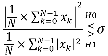
- statistical hypothesis test unit 230 is configured for applying a coherent GRLT algorithm to the processed complex signals (i.e., the processed first complex signal, the processed second complex signal and/or the processed combined complex signal) to identify LOS or NLOS conditions.
- N is the number of received non-periodic signals
- x k is the processed complex signals
- H 0 is the NLOS hypothesis
- H 1 is the LOS hypothesis
- ⁇ is a predetermined threshold.
- the threshold value ⁇ is obtained from the determination of a receiver operating characteristic (ROC) curve, where the ROC curve is a plot of the probability of detection (Pd) vs.
- ROC receiver operating characteristic
- the probability of detection (Pd) is the probability of saying that "1” is true given that event "1” occurred.
- the probability of false alarm (Pfa) is the probability of saying that "1” is true given that the "0” event occurred.
- the "1" event indicates LOS conditions
- the "0" event indicates NLOS conditions
- the "1" event indicates NLOS conditions
- the "0” event indicates LOS conditions.
- the hypothesis criterion of relation (5) is defined to get rid of the random phase ⁇ component which varies from processed complex signals to processed complex signals over the considered measurement window.
- the idea is to average the first cluster amplitude in real and imaginary parts. In the complex plan, this could be illustrated as the superposition of vectors where each vector is defined by the real/imaginary amplitude of each processed complex signals.
- the numerator of the hypothesis criterion of relation (5) which takes the modulus of the amplitude mean of the processed complex signals, corresponds in the complex plan, to length of the superposition of said vectors. Further, it is assumed that the bisector angle of arrival ⁇ is constant over the considered measurement window.
- statistical hypothesis test unit 230 comprises a memory unit 231 for storing the processed complex signals wherein memory unit 231 is configured to discard a predetermined number of processed complex signals after the applying of the GRLT algorithm.
- memory unit 231 is a first-in-first-out (FIFO) memory which is configured to store a first predetermined number of processed complex signals at a time and discard a second predetermined number of processed complex signals before storing new processed complex signals.
- the first and second predetermined numbers have different values. For instance, the first predetermined number is equal to ten and the second predetermined number is equal to two. In that case, ever since two new processed complex signals are to be stored on memory unit 231, then the two oldest previously stored processed complex signals are discarded from memory unit 231.
- the first and second predetermined numbers have the same value.
- the first and second predetermined numbers are both equal to ten. In that case, ever since ten new processed complex signals are to be stored on memory unit 231, then all the previously stored processed complex signals are discarded from memory unit 231.
- each received non-periodic signal may have different bisector angle of arrival ⁇ as nodes 120b and 120c are configured to be in motion relatively to each other.
- This variation may have a dramatic impact on the performance of the coherent GRLT algorithm.
- the numerator of coherent GRLT algorithm as shown in relation (5) defines a sum of complex amplitudes which may suffer from a varying phase due to a variation of the bisector angle of arrival ⁇ .
- the regression analysis is performed on the phase component extracted from the processed complex signals.
- the "best fit" line or curve is then applied to the plurality of time points so as to obtain the phase variation resulting from the variation of the bisector angle of arrival ⁇ .
- the phase variation is used for compensating the phase component extracted from the processed complex signals.
- the compensated phase components are reintroduced into the processed complex signals before applying the GRLT algorithm.
- the regression analysis is performed separately on real and imaginary parts of the processed complex signals. Then, the phase to be used for compensating the original samples is estimated as the phase of the fitted pairs (I/Q) at the plurality of time points.
- apparatus 200 further comprises a curve fitter 240.
- Curve fitter 240 is configured for applying a curve fitting algorithm to the processed complex signals (i.e., the processed first complex signal, the processed second complex signal and/or the processed combined complex signal), thereby generating a best-fit curve defining a variation of the phase component of the processed complex signals over time.
- a curve fitting algorithm i.e., the processed first complex signal, the processed second complex signal and/or the processed combined complex signal
- Figure 4 illustrates an exemplary best fit polynomial curve 410 obtained from on a plurality of processed complex signals 420.
- channel processor 220 is further configured for estimating phase compensated processed complex signals from the best-fit curve based on the plurality of time points.
- statistical hypothesis test unit 230 is further configured for applying the coherent GRLT algorithm to the phase compensated processed complex signals.
- a receiver adapted for vehicular communication 100 and which includes apparatus 200 is also claimed.
- embodiments of the proposed solution may also be implemented in a method 500 for identifying line of sight LOS and NLOS conditions in a multipath channel of vehicular communication 100 as already described above.
- Such method may include:
- the identifying comprises estimating a time of arrival of the clusters.
- the processing comprises:
- the processing comprises:
- N is the number of received non-periodic signals
- x k is the processed complex signal
- H 0 is the NLOS hypothesis
- H 1 is the LOS hypothesis
- ⁇ is a predetermined threshold.
- the above-proposed method may also be performed by a computer program embodied in a non-transitory computer readable storage medium.
Landscapes
- Engineering & Computer Science (AREA)
- Computer Networks & Wireless Communication (AREA)
- Signal Processing (AREA)
- Power Engineering (AREA)
- Physics & Mathematics (AREA)
- Radar, Positioning & Navigation (AREA)
- General Physics & Mathematics (AREA)
- Remote Sensing (AREA)
- Electromagnetism (AREA)
- Position Fixing By Use Of Radio Waves (AREA)
- Radio Transmission System (AREA)
- Variable-Direction Aerials And Aerial Arrays (AREA)
- Mobile Radio Communication Systems (AREA)
Description
- This invention relates to an apparatus and a method of identifying line of sight, LOS, and non-line of sight, NLOS, conditions in a multipath channel of a vehicular communication system. Similar methods and apparatuses are know from E. R. Jativa and J. Vidal, "First arrival detection for positioning in mobile channels," in Proceedings of 13th IEEE International Symposium on Personal, Indoor and Mobile Radio Communications (PIMRC '02), vol. 4, pp. 1540-1544, Lisbon, Portugal, September 2002; Ridha Hamila, Abdelmonaem Lakhzouri. A Highly Efficient Generalized Teager-Kaiser-Based Technique for LOS Estimation in WCDMA Mobile Positioning, EURASIP Journal on Advances in Signal Processing, 2005, 685032, DOI: 10.1155/ASP.2005.698; and J. Borras, P. Hatrack, and N. B. Mandayam, "Decision theoretic framework for NLOS identification," Proc. IEEE 48th Vehicular Technology Conf. (VTC'98 Spring), vol. 2, Ottawa, Canada, pp. 1583-1587, 18-21 May, 1998.
- Location-aware wireless applications are in need of accurate localization methods. A typical application is the localization of a vehicle from one or several base stations in a vehicular cooperative communication networks such a Vehicle-to-everything (V2X) communication systems.
- One challenge for localization system is to successfully mitigate non-line of sight (NLOS) effects by identifying whether the channel is a line of sight (LOS) channel or a NLOS channel. Indeed, the delay estimation error caused by a NLOS channel is the most serious one of those factors that affects the estimation accuracy of localization. The LOS channel can be understood as a transmitter in line of sight with a receiver while a NLOS channel can be understood as a transmitter in non-line of sight with a receiver.
- In vehicular communication systems, known localization methods use triangulation techniques which are based on measurements of received signal strengths (RSS), time of arrival (ToA), time difference of arrival (TDoA) or more generally angles of arrival (AoA) between two or more nodes. However, it has been shown that NLOS propagation increases RSS, ToA and TDoA measurements errors and thus generates large localization error. To avoid the impact of NLOS on localization performance, a node should identify NLOS channel conditions.
- Therefore, there is a need for discriminating between LOS and NLOS channel conditions to improve localization accuracy.
- The present invention provides an apparatus and a method of identifying line of sight, LOS, and non-line of sight, NLOS, conditions in a multipath channel of a vehicular communication system, as described in the accompanying claims. Specific embodiments of the invention are set forth in the dependent claims. These and other aspects of the invention will be apparent from an elucidated with reference to the embodiments described hereinafter.
- Further details, aspects and embodiments of the proposed solution will be described, by way of example only, with reference to the drawings. In the drawings, like or similar reference numbers are used to identify like or functionally similar elements. Elements in the figures are illustrated for simplicity and clarity and have not necessarily been drawn to scale.
-
FIG. 1 is an exemplary vehicular communication system. -
FIG. 2 is a block diagram illustrating an apparatus in accordance with embodiments of the subject application. -
FIG. 3 is a diagram of an exemplary channel impulse response estimate. -
FIG. 4 is a diagram of an exemplary best-fit curve. -
FIG. 5 is a flow chart of a method in accordance with an embodiment of the subject application. - The general context of the invention is the detection of the line of sight (LOS) and non-line of sight (NLOS) conditions of the radio channel between two nodes of a vehicular communication system, where one node receives at random times radio packets transmitted by another node. Further, it is needed to perform the detection solely using the received radio signal without having any prior knowledge on the surrounding environment.
- It is proposed to equip the receiving node with a dual antenna receiver. Then the proposed solution uses the first cluster of multipath components of channel estimates measured on the two antennas to derive the LOS/NLOS channel conditions based on hypothesis testing.
-
Figure 1 shows an exemplaryvehicular communication system 100.Vehicular communication system 100 may be a Vehicular Ad Hoc Network (VANET) or a Vehicle-to-everything communication network (V2X).Vehicular communication system 100 comprises a plurality of nodes such asbase station 120a andvehicles Nodes node 120a has a fixed position whilenodes node 120a. In another example,nodes nodes node 120c is in motion. - Further in
figure 1 , each ofnodes node 120b is considered as a transmitting node and comprises a transmitter whilenode 120c is considered as a receiving node and comprises a receiver. However, other configurations are allowed without departing from the scope of the invention. For example,node 120c may be considered as a transmitting node andnode 120a may be considered as a receiving node. In the example offigure 1 , transmittingnode 120b is configured to transmit a plurality of non-periodic signals. Receivingnode 120c is configured to receive the plurality of non-periodic signals. One should understand that a non-periodic signal is a signal that cannot be divided into fixed time periods of the same duration. Non-periodic signals are usually referred to as asynchronous or non-slotted signals. -
Figure 2 illustrates anapparatus 200 for identifying line of sight (LOS) and non-line of sight (NLOS) conditions in a multipath channel ofvehicular communication system 100.Apparatus 200 may be included in a receiver (not shown) of receivingnode 120c. Infigure 2 ,apparatus 200 comprises an array of antennas. The array of antennas comprises afirst antenna 201 and asecond antenna 202 which are separated by a separation distance d and configured to be mutually synchronized. In an example,first antenna 201 andsecond antenna 202 are installed with fixed relative position and are so separated to maintain independent channels. In an embodiment,first antenna 201 andsecond antenna 202 are separated by more than half a wavelength. Further, the receiver operating onfirst antenna 201 andsecond antenna 202 shares the same local oscillator (not shown). Therefore,first antenna 201 andsecond antenna 202 are said to be synchronized. Moreover, gain and at least frequency synchronization operations are jointly performed on the signals received at first andsecond antennas - Further in
figure 2 ,apparatus 200 comprises at least, achannel estimator 210, achannel processor 220 and a statisticalhypothesis test unit 230 which are operably coupled together. -
Channel estimator 210 is configured for estimating, at each of the plurality of time points, first and second channel estimates respectively associated with each non-periodic signal received on first andsecond antennas node 120c can be described as a multipath environment where power is received through diffractions and reflections from objects in the surroundings. In that case, it is known that receivingnode 120c may receive multipath components, that is, multiple instances of the same signal at different times, i.e. with different delays, because different portions of the signal are reflected from various objects, such as buildings, moving vehicles or landscape details. In the following description, multipath components with approximately the same directions and delays are considered as clusters. Therefore, each of the clusters corresponds to the signal received from one scatterer.Figure 3 shows an exemplary channelimpulse response estimate 300 comprising twoclusters - In the example of
figure 2 ,channel processor 220 is configured for identifying a cluster in each of the first and second channel estimates, wherein said identified cluster is received earlier in time than the remaining clusters. In the following description, said identified cluster would be considered as the "first" cluster. In an embodiment,channel processor 220 estimates a time of arrival of the clusters for determining the first cluster. - Further,
channel processor 220 is also configured for generating a complex representation of each of the identified clusters, thereby generating first and second complex signals. The complex representation comprises a complex amplitude component and one or more complex phase components. In an example,channel processor 220 comprises a conventional quadrature detector (not shown)). The conventional quadrature detector is operably coupled to each of first andsecond antennas second antennas second antennas channel processor 220 generates the first and second complex signals based on the complex numbers and the phase components. - It has been shown that if the number of scatterers of a multipath channel is large enough, the amplitude of the first cluster can be modelled as a zero mean circularly-symmetric random complex Gaussian process irrespective of the distribution of the individual multipath components. It has been further shown that when the multipath channel also includes a component path which is stronger than the other paths, said dominant path being usually known as the LOS component or the deterministic component of the Rice model, the amplitude of the first cluster can be modelled as a circularly-symmetric random complex Gaussian process with an complex mean of A × e -jγ where A is a real number and γ exhibits the complex character of A.
- In an example, based on the foregoing, the first and second complex signals associated with the first clusters can be mathematically represented according to following relation (1):

second antennas antennas second antennas second antennas vehicular communication system 100, b rx1 is a noise component present onfirst antenna 201, b rx2 is a noise component present on the second antenna. One should note that the noise components b rx1 and b rx2 may comprise Rayleigh noise components of the cluster amplitude and/or Gaussian noise components resulting from the noisy estimate of the channel response. - As can be noticed from relation (1), the first cluster complex amplitude is affected by a random phase ϕ mainly resulting from the Doppler shift and the frequency synchronization errors due to the non-periodic nature of the received signals. Further, it is also noted that the random phase ϕ is present on both first and second complex signals. Therefore, one can take advantage of the foregoing and get rid of the random phase ϕ.
- Returning back to
figure 2 ,channel processor 220 is configured for processing the first complex signal so as to remove phase components which are in common with phase components associated with the second complex signal, thereby creating a processed first complex signal. - In an embodiment,
channel processor 220 creates the processed first complex signal according to following relation (2):
x rx1 is the processed first complex signal, x rx1 is the first complex signal, x rx2 is the second complex signal and arg(·) represents the complex argument of a given complex number. - In another embodiment,
channel processor 220 processes the second complex signal so as to remove phase components which are in common with phase components associated with the first complex signal, thereby creating a processed second complex signal. Further,channel processor 220 creates the processed second complex signal according to following relation (3):
x rx2 is the processed second complex signal, x rx1 is the first complex signal, x rx2 is the second complex signal and arg(·) represents the complex argument of a given complex number. - In yet another embodiment,
channel processor 220 processes the first and second complex signals so as to remove phase components which are in common in first and second complex signals, thereby creating a processed combined complex signal. Further,channel processor 220 creates the processed combined complex signal according to following relation (4):
x rx is the processed combined complex signal, x rx1 is the first complex signal, x rx2 * is the complex conjugate of the second complex signal and arg(·) represents the complex argument of a given complex number. - Further, it has been noted that when the multipath channel is in NLOS conditions, the first cluster coefficients correspond to a zero-mean complex Gaussian process while in LOS conditions, the first cluster coefficients correspond to a complex Gaussian process with a complex mean (see above, A × e-jγ ). Therefore, it has been concluded that the identification of LOS/NLOS channel conditions can be based on the detection of an unknown complex constant level in a Gaussian noise, that is, the fast fading and additive noise due to channel estimation.
- It has been found that hypothesis testing could be used to perform that identification. In that case, the phenomenon that is tested is whether or not a transmitter and a receiver are in LOS conditions. The foregoing can be reformulated as two hypotheses:
- H0 = NLOS conditions hypothesis, and
- H1 = LOS conditions hypothesis.
- Based on the foregoing, it is proposed to perform a hypothesis testing based on a coherent generalized likelihood ratio test, GRLT, algorithm that operates on the normalized mean of a set of observations.
- Referring back to
figure 2 , statisticalhypothesis test unit 230 is configured for applying a coherent GRLT algorithm to the processed complex signals (i.e., the processed first complex signal, the processed second complex signal and/or the processed combined complex signal) to identify LOS or NLOS conditions. - In an embodiment, statistical
hypothesis test unit 230 applies the coherent GRLT algorithm according to following relation (5):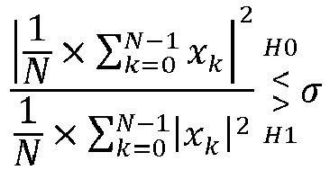
- The hypothesis criterion of relation (5) is defined to get rid of the random phase ϕ component which varies from processed complex signals to processed complex signals over the considered measurement window. The idea is to average the first cluster amplitude in real and imaginary parts. In the complex plan, this could be illustrated as the superposition of vectors where each vector is defined by the real/imaginary amplitude of each processed complex signals. In that case, the numerator of the hypothesis criterion of relation (5) which takes the modulus of the amplitude mean of the processed complex signals, corresponds in the complex plan, to length of the superposition of said vectors. Further, it is assumed that the bisector angle of arrival θ is constant over the considered measurement window.
- In another embodiment, statistical
hypothesis test unit 230 comprises amemory unit 231 for storing the processed complex signals whereinmemory unit 231 is configured to discard a predetermined number of processed complex signals after the applying of the GRLT algorithm. In an embodiment,memory unit 231 is a first-in-first-out (FIFO) memory which is configured to store a first predetermined number of processed complex signals at a time and discard a second predetermined number of processed complex signals before storing new processed complex signals. In an example, the first and second predetermined numbers have different values. For instance, the first predetermined number is equal to ten and the second predetermined number is equal to two. In that case, ever since two new processed complex signals are to be stored onmemory unit 231, then the two oldest previously stored processed complex signals are discarded frommemory unit 231. In another example, the first and second predetermined numbers have the same value. For instance, the first and second predetermined numbers are both equal to ten. In that case, ever since ten new processed complex signals are to be stored onmemory unit 231, then all the previously stored processed complex signals are discarded frommemory unit 231. - In the context of vehicular communications such as in
vehicular communication system 100, it often occurs that the bisector angle of arrival θ experienced on theantenna array nodes nodes - However, due to physical constraints, such as the angular speed of
nodes antennas - A possible solution need to take into consideration that non-periodic signals are received by
node 120c, sporadically, at a plurality of time points. Therefore, it is proposed to perform a regression analysis on the processed complex signals and the plurality of time points to find a "best fit" regression curve describing the bisector angle of arrival θ variations of the processed complex signals as a function of the plurality of time points. It is recalled that regression analysis also known as curve fitting is a statistical technic used to determine the "best fit" line or curve for a series of data points. Finally, after obtaining the "best fit" line or curve associated with processed complex signals as a function of the plurality of time points, it is proposed to compensate for these variations by rectifying the processed complex signals based on the variation of the bisector angle of arrival θ obtained from applying the plurality of time points to "best fit" line or curve. In an example, the regression analysis is performed on the phase component extracted from the processed complex signals. In that example, the "best fit" line or curve is then applied to the plurality of time points so as to obtain the phase variation resulting from the variation of the bisector angle of arrival θ. Then, the phase variation is used for compensating the phase component extracted from the processed complex signals. Finally, the compensated phase components are reintroduced into the processed complex signals before applying the GRLT algorithm. In another example, the regression analysis is performed separately on real and imaginary parts of the processed complex signals. Then, the phase to be used for compensating the original samples is estimated as the phase of the fitted pairs (I/Q) at the plurality of time points. - Referring again to
figure 2 ,apparatus 200 further comprises acurve fitter 240.Curve fitter 240 is configured for applying a curve fitting algorithm to the processed complex signals (i.e., the processed first complex signal, the processed second complex signal and/or the processed combined complex signal), thereby generating a best-fit curve defining a variation of the phase component of the processed complex signals over time. For example, one can consider conventional curve fitting algorithms such as those based on a least-squares algorithms, weighted least-squares algorithms, robust least-squares algorithms, non-linear least-squares algorithms and spline algorithms.Figure 4 illustrates an exemplary best fitpolynomial curve 410 obtained from on a plurality of processed complex signals 420. Further,channel processor 220 is further configured for estimating phase compensated processed complex signals from the best-fit curve based on the plurality of time points. Finally, statisticalhypothesis test unit 230 is further configured for applying the coherent GRLT algorithm to the phase compensated processed complex signals. - A receiver adapted for
vehicular communication 100 and which includesapparatus 200 is also claimed. - Further, as shown in
figure 5 , embodiments of the proposed solution may also be implemented in amethod 500 for identifying line of sight LOS and NLOS conditions in a multipath channel ofvehicular communication 100 as already described above. Such method may include: - at S510, estimating, at each of the plurality of time points, first and second channel estimates respectively associated with each non-periodic signal received on the first and second antennas, each of the first and second channel estimates having multipath components arranged in clusters,
- at S520, identifying a cluster of multipath components in each of the first and second channel estimates, wherein said identified cluster is received earlier in time than the remaining clusters,
- at S530, generating a complex representation of each of the identified clusters comprising a complex amplitude component and one or more complex phase components, thereby generating first and second complex signals,
- at S540, processing the first complex signal so as to remove phase components which are in common with phase components associated with the second complex signal, thereby creating a processed first complex signal,
- at S550, applying a coherent generalized likelihood ratio test, GRLT, algorithm to the processed complex signals to identify LOS or NLOS conditions
- In embodiments of the method, the identifying comprises estimating a time of arrival of the clusters.
- In one embodiment of the method, the processing comprises creating the processed first complex signal according to following relation,

x rx1 is the processed first complex signal, x rx1 is the first complex signal and x rx2 is the second complex signal. - In alternative embodiments of the method, the processing comprises:
- processing the second complex signal so as to remove phase components which are in common with phase components associated with the first complex signal, thereby creating a processed second complex signal, and
- creating the processed second complex signal according to following relation,

x rx2 is the processed second complex signal, x rx1 is the first complex signal and x rx2 is the second complex signal. - In another embodiment of the method, the processing comprises:
- processing first and second complex signals so as to remove phase components which are in common in first and second complex signals, thereby creating a processed combined complex signal, and
- creating the processed combined complex signal according to following relation,

x rx is the processed combined complex signal, x rx1 is the first complex signal and x rx2* is the complex conjugate of the second complex signal. - In embodiments of the method, the coherent GRLT algorithm is determined according to following relation,

- In other embodiments of the method, it is further included, discarding a predetermined number of processed complex signals after the applying of GRLT algorithm.
- In one embodiment of the method, it is further included:
- applying a curve fitting algorithm to the processed complex signals, thereby generating a best-fit curve defining a variation of the phase component of the processed complex signals over time,
- estimating phase compensated processed complex signals from the best-fit curve based on the plurality of time points, and
- applying the coherent GRLT to the phase compensated processed complex signals.
- The above-proposed method may also be performed by a computer program embodied in a non-transitory computer readable storage medium.
- In the foregoing specification, the proposed solution has been described regarding specific examples of embodiments of the proposed solution. It will, however, be evident that various modifications and changes may be made therein without departing from the broader scope of the proposed solution as set forth in the appended claims.
Claims (16)
- A receiver apparatus (200) for identifying line of sight, LOS, and non-line of sight, NLOS, conditions in a multipath channel of a vehicular communication system (100), the communication system comprising at least a transmitting node (120b) and a receiving node (120c), which are configured to be in relative motion with respect to each other, the receiver apparatus (200) included in a receiver of the receiver node (120c), the transmitting node being further configured to transmit a plurality of non-periodic signals at a plurality of time points, the receiver apparatus (200) comprising first and second antennas (201, 202) which are separated by a separation distance and configured to be mutually synchronized to a same oscillator and being configured to receive the plurality of non-periodic signals at the plurality of time points, the receiver apparatus (200) further comprising:- a channel estimator (210) configured for estimating, at each of the plurality of time points, first and second channel estimates respectively associated with each non-periodic signal received on the first and second antennas, each of the first and second channel estimates having multipath components arranged in clusters, a cluster comprising multipath components with approximately the same directions and delays; and- a channel processor (220) configured for:- identifying a cluster of multipath components in each of the first and second channel estimates, wherein said identified cluster is received earlier in time than the remaining clusters,- generating a complex representation of each of the identified clusters comprising a complex amplitude component and one or more complex phase components, thereby generating first and second complex signals,- processing the first complex signal and/or the second complex signal so as to remove a phase component which is in common in the first and second complex signals, thereby creating a processed complex signal, the phase component resulting from the Doppler shift and the frequency synchronization errors due to the non-periodic nature of the received plurality of non-periodic signals,- a statistical hypothesis test unit (230) for applying a coherent generalized likelihood ratio test, GRLT, algorithm to the processed complex signal to identify LOS or NLOS conditions.
- The receiver apparatus of claim 1, wherein the channel processor is further configured for estimating a time of arrival of the clusters.
- The receiver apparatus of claims 1 or 2, wherein the channel processor is further configured for creating the processed complex signal according to following relation,

x rx1 is the processed complex signal, x rx1 is the first complex signal and x rx2 is the second complex signal. - The receiver apparatus of claims 1 or 2, wherein the channel processor is further configured for creating the processed complex signal according to following relation,

x rx2 is the processed complex signal, x rx1 is the first complex signal and x rx2 is the second complex signal. - The receiver apparatus of claims 1 or 2, wherein the channel processor is further configured for creating the processed complex signal according to following relation,

x rx is the processed complex signal, x rx1 is the first complex signal and x rx2* is the complex conjugate of the second complex signal. - The receiver apparatus of claims 1, 2, 3, 4 or 5 wherein statistical hypothesis test unit is further configured to determine the coherent GRLT algorithm according to following relation,

- The receiver apparatus of claim 6 wherein the statistical hypothesis test unit comprises a memory unit (231) for storing the processed complex signals wherein the memory unit is configured to discard a predetermined number of processed complex signals after the applying of the GRLT algorithm.
- The receiver apparatus of claims 1, 2, 3, 4, 5, 6 and 7 further comprising a curve fitter (240) for applying a curve fitting algorithm to the processed complex signals, thereby generating a best-fit curve defining a variation of the phase component of the processed complex signals over time,
wherein,- the channel processor being further configured for estimating phase compensated processed complex signals from the best-fit curve based on the plurality of time points, and- the statistical hypothesis test unit being further configured for applying the coherent GRLT to the phase compensated processed complex signals. - A method (500), carried out by a receiver apparatus (200), the method being configured for identifying line of sight, LOS, and non-line of sight, NLOS, conditions in a multipath channel of a vehicular communication system (100), the communication system comprising at least a transmitting node (120b) and a receiving node (120c), which are configured to be in relative motion with respect to each other, ther receiver apparatus (200) included in a receiver of the receiver node (120c), the transmitting node being further configured to transmit a plurality of non-periodic signals at a plurality of time points, the receiver apparatus (200) comprising first and second antennas (201, 202) which are separated by a separation distance and configured to be mutually synchronized to a same oscillator and being configured to receive the plurality of non-periodic signals at the plurality of time points, the method comprising:- estimating (510), at each of the plurality of time points, first and second channel estimates respectively associated with each non-periodic signal received on the first and second antennas, each of the first and second channel estimates having multipath components arranged in clusters, a cluster comprising multipath components with approximately the same directions and delays,- identifying (520) a cluster of multipath components in each of the first and second channel estimates, wherein said identified cluster is received earlier in time than the remaining clusters,- generating (530) a complex representation of each of the identified clusters comprising a complex amplitude component and one or more complex phase components, thereby generating first and second complex signals,- processing (540) the first complex signal and/or the second complex signal so as to remove a phase component which is in common in the first and second complex signals, thereby creating a processed complex signal, the phase component resulting from the Doppler shift and the frequency synchronization errors due to the non-periodic nature of the received plurality of non-periodic signals,- applying (550) a coherent generalized likelihood ratio test, GRLT, algorithm to the processed complex signal to identify LOS or NLOS conditions.
- The method of claim 9, wherein the identifying comprises estimating a time of arrival of the clusters.
- The method of claims 9 or 10, wherein the processing comprises creating the processed complex signal according to following relation,

x rx1 is the processed complex signal, x rx1 is the first complex signal and x rx2 is the second complex signal. - The method of claims 9 or 10, wherein the processing comprises creating the processed complex signal according to following relation,

x rx2 is the processed complex signal, x rx1 is the first complex signal and x rx2 is the second complex signal. - The method of claims 9 or 10, wherein the processing comprises creating the processed complex signal according to following relation,

x rx is the processed complex signal, x rx1 is the first complex signal and x rx2 * is the complex conjugate of the second complex signal. - The method of claims 9, 10, 11, 12 or 13 wherein the coherent GRLT algorithm is determined according to following relation,
- The method of claim 14 further comprising discarding a predetermined number of processed complex signals after the applying of GRLT algorithm.
- The method of claims 9, 10, 11, 12, 13, 14 and 15 further comprising:- applying a curve fitting algorithm to the processed complex signals, thereby generating a best-fit curve defining a variation of the phase component of the processed complex signals over time,- estimating phase compensated processed complex signals from the best-fit curve based on the plurality of time points, and- applying the coherent GRLT to the phase compensated processed complex signals.
Priority Applications (5)
| Application Number | Priority Date | Filing Date | Title |
|---|---|---|---|
| EP17305872.8A EP3425418B1 (en) | 2017-07-06 | 2017-07-06 | Method and apparatus for distinghuishing line of sight from non line of sight in vehicular communication systems |
| PCT/JP2018/022131 WO2019009016A1 (en) | 2017-07-06 | 2018-06-04 | Method and apparatus for distinguishing line of sight from non line of sight in vehicular communication systems |
| JP2019547731A JP2020511829A (en) | 2017-07-06 | 2018-06-04 | Device for distinguishing between line-of-sight and non-line-of-sight |
| US16/614,240 US20210409132A1 (en) | 2017-07-06 | 2018-06-04 | Apparatus for identifying line of sight and non-line of sight |
| CN201880044421.0A CN110869791A (en) | 2017-07-06 | 2018-06-04 | Method and apparatus for distinguishing line of sight from non-line of sight in a vehicle communication system |
Applications Claiming Priority (1)
| Application Number | Priority Date | Filing Date | Title |
|---|---|---|---|
| EP17305872.8A EP3425418B1 (en) | 2017-07-06 | 2017-07-06 | Method and apparatus for distinghuishing line of sight from non line of sight in vehicular communication systems |
Publications (2)
| Publication Number | Publication Date |
|---|---|
| EP3425418A1 EP3425418A1 (en) | 2019-01-09 |
| EP3425418B1 true EP3425418B1 (en) | 2020-06-03 |
Family
ID=59350833
Family Applications (1)
| Application Number | Title | Priority Date | Filing Date |
|---|---|---|---|
| EP17305872.8A Active EP3425418B1 (en) | 2017-07-06 | 2017-07-06 | Method and apparatus for distinghuishing line of sight from non line of sight in vehicular communication systems |
Country Status (5)
| Country | Link |
|---|---|
| US (1) | US20210409132A1 (en) |
| EP (1) | EP3425418B1 (en) |
| JP (1) | JP2020511829A (en) |
| CN (1) | CN110869791A (en) |
| WO (1) | WO2019009016A1 (en) |
Families Citing this family (12)
| Publication number | Priority date | Publication date | Assignee | Title |
|---|---|---|---|---|
| US10142137B2 (en) | 2017-03-02 | 2018-11-27 | Micron Technology, Inc. | Wireless devices and systems including examples of full duplex transmission |
| US11941516B2 (en) | 2017-08-31 | 2024-03-26 | Micron Technology, Inc. | Cooperative learning neural networks and systems |
| US10554375B2 (en) | 2017-09-11 | 2020-02-04 | Micron Technology, Inc. | Full duplex device-to-device cooperative communication |
| US11206050B2 (en) | 2018-02-06 | 2021-12-21 | Micron Technology, Inc. | Self interference noise cancellation to support multiple frequency bands |
| CN109756284B (en) * | 2019-02-18 | 2021-05-25 | 南京航空航天大学 | Rapid construction method of vehicle-mounted node communication model for dynamic topology Internet of vehicles |
| US10979097B2 (en) | 2019-09-05 | 2021-04-13 | Micron Technology, Inc. | Wireless devices and systems including examples of full duplex transmission using neural networks or recurrent neural networks |
| CN114599992B (en) * | 2019-10-31 | 2025-07-29 | 认知系统公司 | Using MIMO training fields for motion detection |
| US11258473B2 (en) | 2020-04-14 | 2022-02-22 | Micron Technology, Inc. | Self interference noise cancellation to support multiple frequency bands with neural networks or recurrent neural networks |
| WO2021249634A1 (en) * | 2020-06-10 | 2021-12-16 | Nokia Technologies Oy | Signal classification |
| CN114007183B (en) * | 2020-07-28 | 2022-11-04 | 华为技术有限公司 | Triggering method and communication device of positioning mode |
| CN113886209B (en) * | 2021-10-14 | 2023-07-11 | 东风汽车集团股份有限公司 | Simulation verification platform and method for V2X early warning function |
| WO2023092357A1 (en) * | 2021-11-24 | 2023-06-01 | 株式会社Ntt都科摩 | Receiving device and transmitting device |
Family Cites Families (2)
| Publication number | Priority date | Publication date | Assignee | Title |
|---|---|---|---|---|
| US9207305B2 (en) * | 2012-09-05 | 2015-12-08 | Khalifa University Of Science, Technology And Research | Methods and devices for channel identification |
| US10158436B2 (en) * | 2015-02-17 | 2018-12-18 | Mitsubishi Electric Corporation | Receiver apparatus and reception method |
-
2017
- 2017-07-06 EP EP17305872.8A patent/EP3425418B1/en active Active
-
2018
- 2018-06-04 CN CN201880044421.0A patent/CN110869791A/en not_active Withdrawn
- 2018-06-04 US US16/614,240 patent/US20210409132A1/en not_active Abandoned
- 2018-06-04 JP JP2019547731A patent/JP2020511829A/en not_active Ceased
- 2018-06-04 WO PCT/JP2018/022131 patent/WO2019009016A1/en not_active Ceased
Non-Patent Citations (1)
| Title |
|---|
| None * |
Also Published As
| Publication number | Publication date |
|---|---|
| WO2019009016A1 (en) | 2019-01-10 |
| JP2020511829A (en) | 2020-04-16 |
| US20210409132A1 (en) | 2021-12-30 |
| CN110869791A (en) | 2020-03-06 |
| EP3425418A1 (en) | 2019-01-09 |
Similar Documents
| Publication | Publication Date | Title |
|---|---|---|
| EP3425418B1 (en) | Method and apparatus for distinghuishing line of sight from non line of sight in vehicular communication systems | |
| Bultitude | Estimating frequency correlation functions from propagation measurements on fading radio channels: a critical review | |
| Wong et al. | Using WLAN infrastructure for angle-of-arrival indoor user location | |
| Chen et al. | Achieving centimeter-accuracy indoor localization on WiFi platforms: A multi-antenna approach | |
| US20240196361A1 (en) | Method of positioning a node in a cellular network | |
| Mendrzik et al. | Joint localization and mapping through millimeter wave MIMO in 5G systems | |
| Al-Jazzar et al. | ML and Bayesian TOA location estimators for NLOS environments | |
| EP4350573A2 (en) | Robust toa-estimation using convolutional neural networks (or other function approximations) on randomized channel models | |
| KR20220081797A (en) | Mehtod and device for precise positioning for wireless communication system | |
| US20090204362A1 (en) | Indoor location determination system and method | |
| EP1425868B1 (en) | Radio station and radio system with modeling of multipath propagation | |
| Van Herbruggen et al. | Single anchor localization by combining UWB angle-of-arrival and two-way-ranging: An experimental evaluation of the DW3000 | |
| Mollén et al. | Joint multistatic sensing of transmitter and target in OFDM-based JCAS system | |
| US11841451B2 (en) | Communication device and method | |
| Taghavi et al. | Fundamental and practical performance assessment in monostatic ISAC: From sub-6GHz to sub-THz | |
| Ribeiro et al. | Propagation parameter estimation in MIMO systems using mixture of angular distributions model | |
| Kuxdorf-Alkirata et al. | A self-calibrating bidirectional indoor localization system | |
| Alteneiji et al. | Indoor localization in multi-path environment based on AoA with particle filter | |
| Han et al. | Pilot-aided simultaneous communication and localisation (PASCAL) under practical imperfections | |
| Gentner et al. | Multipath assisted positioning using a single antenna with angle of arrival estimations | |
| Neunteufel et al. | Bayesian CRLB for Blind Indoor Localization with Imperfect Receiver Synchronization | |
| Ruppert et al. | An SDR-Based Evaluation of Maximum Likelihood Estimator and MUSIC Algorithm for TDOA in 5G Campus Networks | |
| Wang et al. | A comparison of outdoor-to-indoor wideband propagation at S-band and C-band for ranging | |
| Jiang et al. | Near-field localization in uav-mounted hris system | |
| US20250212089A1 (en) | Methods and apparatuses relating to wireless communications |
Legal Events
| Date | Code | Title | Description |
|---|---|---|---|
| PUAI | Public reference made under article 153(3) epc to a published international application that has entered the european phase |
Free format text: ORIGINAL CODE: 0009012 |
|
| STAA | Information on the status of an ep patent application or granted ep patent |
Free format text: STATUS: THE APPLICATION HAS BEEN PUBLISHED |
|
| AK | Designated contracting states |
Kind code of ref document: A1 Designated state(s): AL AT BE BG CH CY CZ DE DK EE ES FI FR GB GR HR HU IE IS IT LI LT LU LV MC MK MT NL NO PL PT RO RS SE SI SK SM TR |
|
| AX | Request for extension of the european patent |
Extension state: BA ME |
|
| STAA | Information on the status of an ep patent application or granted ep patent |
Free format text: STATUS: REQUEST FOR EXAMINATION WAS MADE |
|
| 17P | Request for examination filed |
Effective date: 20190705 |
|
| RBV | Designated contracting states (corrected) |
Designated state(s): AL AT BE BG CH CY CZ DE DK EE ES FI FR GB GR HR HU IE IS IT LI LT LU LV MC MK MT NL NO PL PT RO RS SE SI SK SM TR |
|
| GRAP | Despatch of communication of intention to grant a patent |
Free format text: ORIGINAL CODE: EPIDOSNIGR1 |
|
| STAA | Information on the status of an ep patent application or granted ep patent |
Free format text: STATUS: GRANT OF PATENT IS INTENDED |
|
| RIC1 | Information provided on ipc code assigned before grant |
Ipc: H04L 25/02 20060101ALI20200212BHEP Ipc: H04B 17/318 20150101ALI20200212BHEP Ipc: H04B 17/391 20150101ALN20200212BHEP Ipc: G01S 5/02 20100101AFI20200212BHEP |
|
| INTG | Intention to grant announced |
Effective date: 20200312 |
|
| RIN1 | Information on inventor provided before grant (corrected) |
Inventor name: BOUTTIER, ARNAUD Inventor name: NOURISSON, XAVIER Inventor name: VERCASSON, GUILLAUME |
|
| GRAS | Grant fee paid |
Free format text: ORIGINAL CODE: EPIDOSNIGR3 |
|
| GRAA | (expected) grant |
Free format text: ORIGINAL CODE: 0009210 |
|
| STAA | Information on the status of an ep patent application or granted ep patent |
Free format text: STATUS: THE PATENT HAS BEEN GRANTED |
|
| AK | Designated contracting states |
Kind code of ref document: B1 Designated state(s): AL AT BE BG CH CY CZ DE DK EE ES FI FR GB GR HR HU IE IS IT LI LT LU LV MC MK MT NL NO PL PT RO RS SE SI SK SM TR |
|
| REG | Reference to a national code |
Ref country code: GB Ref legal event code: FG4D |
|
| REG | Reference to a national code |
Ref country code: CH Ref legal event code: EP Ref country code: AT Ref legal event code: REF Ref document number: 1277556 Country of ref document: AT Kind code of ref document: T Effective date: 20200615 |
|
| REG | Reference to a national code |
Ref country code: DE Ref legal event code: R096 Ref document number: 602017017620 Country of ref document: DE |
|
| REG | Reference to a national code |
Ref country code: LT Ref legal event code: MG4D |
|
| PG25 | Lapsed in a contracting state [announced via postgrant information from national office to epo] |
Ref country code: LT Free format text: LAPSE BECAUSE OF FAILURE TO SUBMIT A TRANSLATION OF THE DESCRIPTION OR TO PAY THE FEE WITHIN THE PRESCRIBED TIME-LIMIT Effective date: 20200603 Ref country code: FI Free format text: LAPSE BECAUSE OF FAILURE TO SUBMIT A TRANSLATION OF THE DESCRIPTION OR TO PAY THE FEE WITHIN THE PRESCRIBED TIME-LIMIT Effective date: 20200603 Ref country code: SE Free format text: LAPSE BECAUSE OF FAILURE TO SUBMIT A TRANSLATION OF THE DESCRIPTION OR TO PAY THE FEE WITHIN THE PRESCRIBED TIME-LIMIT Effective date: 20200603 Ref country code: GR Free format text: LAPSE BECAUSE OF FAILURE TO SUBMIT A TRANSLATION OF THE DESCRIPTION OR TO PAY THE FEE WITHIN THE PRESCRIBED TIME-LIMIT Effective date: 20200904 Ref country code: NO Free format text: LAPSE BECAUSE OF FAILURE TO SUBMIT A TRANSLATION OF THE DESCRIPTION OR TO PAY THE FEE WITHIN THE PRESCRIBED TIME-LIMIT Effective date: 20200903 |
|
| PGFP | Annual fee paid to national office [announced via postgrant information from national office to epo] |
Ref country code: FR Payment date: 20200724 Year of fee payment: 4 |
|
| REG | Reference to a national code |
Ref country code: NL Ref legal event code: MP Effective date: 20200603 |
|
| PG25 | Lapsed in a contracting state [announced via postgrant information from national office to epo] |
Ref country code: HR Free format text: LAPSE BECAUSE OF FAILURE TO SUBMIT A TRANSLATION OF THE DESCRIPTION OR TO PAY THE FEE WITHIN THE PRESCRIBED TIME-LIMIT Effective date: 20200603 Ref country code: RS Free format text: LAPSE BECAUSE OF FAILURE TO SUBMIT A TRANSLATION OF THE DESCRIPTION OR TO PAY THE FEE WITHIN THE PRESCRIBED TIME-LIMIT Effective date: 20200603 Ref country code: BG Free format text: LAPSE BECAUSE OF FAILURE TO SUBMIT A TRANSLATION OF THE DESCRIPTION OR TO PAY THE FEE WITHIN THE PRESCRIBED TIME-LIMIT Effective date: 20200903 Ref country code: LV Free format text: LAPSE BECAUSE OF FAILURE TO SUBMIT A TRANSLATION OF THE DESCRIPTION OR TO PAY THE FEE WITHIN THE PRESCRIBED TIME-LIMIT Effective date: 20200603 |
|
| REG | Reference to a national code |
Ref country code: AT Ref legal event code: MK05 Ref document number: 1277556 Country of ref document: AT Kind code of ref document: T Effective date: 20200603 |
|
| PG25 | Lapsed in a contracting state [announced via postgrant information from national office to epo] |
Ref country code: AL Free format text: LAPSE BECAUSE OF FAILURE TO SUBMIT A TRANSLATION OF THE DESCRIPTION OR TO PAY THE FEE WITHIN THE PRESCRIBED TIME-LIMIT Effective date: 20200603 Ref country code: NL Free format text: LAPSE BECAUSE OF FAILURE TO SUBMIT A TRANSLATION OF THE DESCRIPTION OR TO PAY THE FEE WITHIN THE PRESCRIBED TIME-LIMIT Effective date: 20200603 |
|
| PG25 | Lapsed in a contracting state [announced via postgrant information from national office to epo] |
Ref country code: ES Free format text: LAPSE BECAUSE OF FAILURE TO SUBMIT A TRANSLATION OF THE DESCRIPTION OR TO PAY THE FEE WITHIN THE PRESCRIBED TIME-LIMIT Effective date: 20200603 Ref country code: AT Free format text: LAPSE BECAUSE OF FAILURE TO SUBMIT A TRANSLATION OF THE DESCRIPTION OR TO PAY THE FEE WITHIN THE PRESCRIBED TIME-LIMIT Effective date: 20200603 Ref country code: IT Free format text: LAPSE BECAUSE OF FAILURE TO SUBMIT A TRANSLATION OF THE DESCRIPTION OR TO PAY THE FEE WITHIN THE PRESCRIBED TIME-LIMIT Effective date: 20200603 Ref country code: CZ Free format text: LAPSE BECAUSE OF FAILURE TO SUBMIT A TRANSLATION OF THE DESCRIPTION OR TO PAY THE FEE WITHIN THE PRESCRIBED TIME-LIMIT Effective date: 20200603 Ref country code: RO Free format text: LAPSE BECAUSE OF FAILURE TO SUBMIT A TRANSLATION OF THE DESCRIPTION OR TO PAY THE FEE WITHIN THE PRESCRIBED TIME-LIMIT Effective date: 20200603 Ref country code: SM Free format text: LAPSE BECAUSE OF FAILURE TO SUBMIT A TRANSLATION OF THE DESCRIPTION OR TO PAY THE FEE WITHIN THE PRESCRIBED TIME-LIMIT Effective date: 20200603 Ref country code: EE Free format text: LAPSE BECAUSE OF FAILURE TO SUBMIT A TRANSLATION OF THE DESCRIPTION OR TO PAY THE FEE WITHIN THE PRESCRIBED TIME-LIMIT Effective date: 20200603 Ref country code: PT Free format text: LAPSE BECAUSE OF FAILURE TO SUBMIT A TRANSLATION OF THE DESCRIPTION OR TO PAY THE FEE WITHIN THE PRESCRIBED TIME-LIMIT Effective date: 20201006 |
|
| REG | Reference to a national code |
Ref country code: DE Ref legal event code: R119 Ref document number: 602017017620 Country of ref document: DE |
|
| PG25 | Lapsed in a contracting state [announced via postgrant information from national office to epo] |
Ref country code: SK Free format text: LAPSE BECAUSE OF FAILURE TO SUBMIT A TRANSLATION OF THE DESCRIPTION OR TO PAY THE FEE WITHIN THE PRESCRIBED TIME-LIMIT Effective date: 20200603 Ref country code: PL Free format text: LAPSE BECAUSE OF FAILURE TO SUBMIT A TRANSLATION OF THE DESCRIPTION OR TO PAY THE FEE WITHIN THE PRESCRIBED TIME-LIMIT Effective date: 20200603 Ref country code: IS Free format text: LAPSE BECAUSE OF FAILURE TO SUBMIT A TRANSLATION OF THE DESCRIPTION OR TO PAY THE FEE WITHIN THE PRESCRIBED TIME-LIMIT Effective date: 20201003 |
|
| REG | Reference to a national code |
Ref country code: CH Ref legal event code: PL |
|
| PG25 | Lapsed in a contracting state [announced via postgrant information from national office to epo] |
Ref country code: MC Free format text: LAPSE BECAUSE OF FAILURE TO SUBMIT A TRANSLATION OF THE DESCRIPTION OR TO PAY THE FEE WITHIN THE PRESCRIBED TIME-LIMIT Effective date: 20200603 |
|
| PLBE | No opposition filed within time limit |
Free format text: ORIGINAL CODE: 0009261 |
|
| STAA | Information on the status of an ep patent application or granted ep patent |
Free format text: STATUS: NO OPPOSITION FILED WITHIN TIME LIMIT |
|
| REG | Reference to a national code |
Ref country code: BE Ref legal event code: MM Effective date: 20200731 |
|
| PG25 | Lapsed in a contracting state [announced via postgrant information from national office to epo] |
Ref country code: IE Free format text: LAPSE BECAUSE OF NON-PAYMENT OF DUE FEES Effective date: 20200706 Ref country code: LI Free format text: LAPSE BECAUSE OF NON-PAYMENT OF DUE FEES Effective date: 20200731 Ref country code: LU Free format text: LAPSE BECAUSE OF NON-PAYMENT OF DUE FEES Effective date: 20200706 Ref country code: DK Free format text: LAPSE BECAUSE OF FAILURE TO SUBMIT A TRANSLATION OF THE DESCRIPTION OR TO PAY THE FEE WITHIN THE PRESCRIBED TIME-LIMIT Effective date: 20200603 Ref country code: CH Free format text: LAPSE BECAUSE OF NON-PAYMENT OF DUE FEES Effective date: 20200731 |
|
| 26N | No opposition filed |
Effective date: 20210304 |
|
| PG25 | Lapsed in a contracting state [announced via postgrant information from national office to epo] |
Ref country code: BE Free format text: LAPSE BECAUSE OF NON-PAYMENT OF DUE FEES Effective date: 20200731 Ref country code: DE Free format text: LAPSE BECAUSE OF NON-PAYMENT OF DUE FEES Effective date: 20210202 Ref country code: SI Free format text: LAPSE BECAUSE OF FAILURE TO SUBMIT A TRANSLATION OF THE DESCRIPTION OR TO PAY THE FEE WITHIN THE PRESCRIBED TIME-LIMIT Effective date: 20200603 |
|
| GBPC | Gb: european patent ceased through non-payment of renewal fee |
Effective date: 20210706 |
|
| PG25 | Lapsed in a contracting state [announced via postgrant information from national office to epo] |
Ref country code: GB Free format text: LAPSE BECAUSE OF NON-PAYMENT OF DUE FEES Effective date: 20210706 |
|
| PG25 | Lapsed in a contracting state [announced via postgrant information from national office to epo] |
Ref country code: TR Free format text: LAPSE BECAUSE OF FAILURE TO SUBMIT A TRANSLATION OF THE DESCRIPTION OR TO PAY THE FEE WITHIN THE PRESCRIBED TIME-LIMIT Effective date: 20200603 Ref country code: MT Free format text: LAPSE BECAUSE OF FAILURE TO SUBMIT A TRANSLATION OF THE DESCRIPTION OR TO PAY THE FEE WITHIN THE PRESCRIBED TIME-LIMIT Effective date: 20200603 Ref country code: FR Free format text: LAPSE BECAUSE OF NON-PAYMENT OF DUE FEES Effective date: 20210731 Ref country code: CY Free format text: LAPSE BECAUSE OF FAILURE TO SUBMIT A TRANSLATION OF THE DESCRIPTION OR TO PAY THE FEE WITHIN THE PRESCRIBED TIME-LIMIT Effective date: 20200603 |
|
| PG25 | Lapsed in a contracting state [announced via postgrant information from national office to epo] |
Ref country code: MK Free format text: LAPSE BECAUSE OF FAILURE TO SUBMIT A TRANSLATION OF THE DESCRIPTION OR TO PAY THE FEE WITHIN THE PRESCRIBED TIME-LIMIT Effective date: 20200603 |