EP3419696B1 - Syringe plunger with hinged flange - Google Patents
Syringe plunger with hinged flange Download PDFInfo
- Publication number
- EP3419696B1 EP3419696B1 EP17709267.3A EP17709267A EP3419696B1 EP 3419696 B1 EP3419696 B1 EP 3419696B1 EP 17709267 A EP17709267 A EP 17709267A EP 3419696 B1 EP3419696 B1 EP 3419696B1
- Authority
- EP
- European Patent Office
- Prior art keywords
- syringe
- plunger
- syringe plunger
- fixed portion
- contact face
- Prior art date
- Legal status (The legal status is an assumption and is not a legal conclusion. Google has not performed a legal analysis and makes no representation as to the accuracy of the status listed.)
- Not-in-force
Links
Images


Classifications
-
- A—HUMAN NECESSITIES
- A61—MEDICAL OR VETERINARY SCIENCE; HYGIENE
- A61M—DEVICES FOR INTRODUCING MEDIA INTO, OR ONTO, THE BODY; DEVICES FOR TRANSDUCING BODY MEDIA OR FOR TAKING MEDIA FROM THE BODY; DEVICES FOR PRODUCING OR ENDING SLEEP OR STUPOR
- A61M5/00—Devices for bringing media into the body in a subcutaneous, intra-vascular or intramuscular way; Accessories therefor, e.g. filling or cleaning devices, arm-rests
- A61M5/14—Infusion devices, e.g. infusing by gravity; Blood infusion; Accessories therefor
- A61M5/142—Pressure infusion, e.g. using pumps
- A61M5/145—Pressure infusion, e.g. using pumps using pressurised reservoirs, e.g. pressurised by means of pistons
- A61M5/1452—Pressure infusion, e.g. using pumps using pressurised reservoirs, e.g. pressurised by means of pistons pressurised by means of pistons
- A61M5/1456—Pressure infusion, e.g. using pumps using pressurised reservoirs, e.g. pressurised by means of pistons pressurised by means of pistons with a replaceable reservoir comprising a piston rod to be moved into the reservoir, e.g. the piston rod is part of the removable reservoir
-
- A—HUMAN NECESSITIES
- A61—MEDICAL OR VETERINARY SCIENCE; HYGIENE
- A61J—CONTAINERS SPECIALLY ADAPTED FOR MEDICAL OR PHARMACEUTICAL PURPOSES; DEVICES OR METHODS SPECIALLY ADAPTED FOR BRINGING PHARMACEUTICAL PRODUCTS INTO PARTICULAR PHYSICAL OR ADMINISTERING FORMS; DEVICES FOR ADMINISTERING FOOD OR MEDICINES ORALLY; BABY COMFORTERS; DEVICES FOR RECEIVING SPITTLE
- A61J15/00—Feeding-tubes for therapeutic purposes
- A61J15/0026—Parts, details or accessories for feeding-tubes
- A61J15/0076—Feeding pumps
-
- A—HUMAN NECESSITIES
- A61—MEDICAL OR VETERINARY SCIENCE; HYGIENE
- A61J—CONTAINERS SPECIALLY ADAPTED FOR MEDICAL OR PHARMACEUTICAL PURPOSES; DEVICES OR METHODS SPECIALLY ADAPTED FOR BRINGING PHARMACEUTICAL PRODUCTS INTO PARTICULAR PHYSICAL OR ADMINISTERING FORMS; DEVICES FOR ADMINISTERING FOOD OR MEDICINES ORALLY; BABY COMFORTERS; DEVICES FOR RECEIVING SPITTLE
- A61J15/00—Feeding-tubes for therapeutic purposes
- A61J15/0026—Parts, details or accessories for feeding-tubes
- A61J15/0096—Provisions for venting
-
- A—HUMAN NECESSITIES
- A61—MEDICAL OR VETERINARY SCIENCE; HYGIENE
- A61M—DEVICES FOR INTRODUCING MEDIA INTO, OR ONTO, THE BODY; DEVICES FOR TRANSDUCING BODY MEDIA OR FOR TAKING MEDIA FROM THE BODY; DEVICES FOR PRODUCING OR ENDING SLEEP OR STUPOR
- A61M39/00—Tubes, tube connectors, tube couplings, valves, access sites or the like, specially adapted for medical use
- A61M39/10—Tube connectors; Tube couplings
-
- A—HUMAN NECESSITIES
- A61—MEDICAL OR VETERINARY SCIENCE; HYGIENE
- A61M—DEVICES FOR INTRODUCING MEDIA INTO, OR ONTO, THE BODY; DEVICES FOR TRANSDUCING BODY MEDIA OR FOR TAKING MEDIA FROM THE BODY; DEVICES FOR PRODUCING OR ENDING SLEEP OR STUPOR
- A61M5/00—Devices for bringing media into the body in a subcutaneous, intra-vascular or intramuscular way; Accessories therefor, e.g. filling or cleaning devices, arm-rests
- A61M5/14—Infusion devices, e.g. infusing by gravity; Blood infusion; Accessories therefor
- A61M5/142—Pressure infusion, e.g. using pumps
- A61M5/145—Pressure infusion, e.g. using pumps using pressurised reservoirs, e.g. pressurised by means of pistons
- A61M5/1452—Pressure infusion, e.g. using pumps using pressurised reservoirs, e.g. pressurised by means of pistons pressurised by means of pistons
- A61M5/1458—Means for capture of the plunger flange
-
- A—HUMAN NECESSITIES
- A61—MEDICAL OR VETERINARY SCIENCE; HYGIENE
- A61M—DEVICES FOR INTRODUCING MEDIA INTO, OR ONTO, THE BODY; DEVICES FOR TRANSDUCING BODY MEDIA OR FOR TAKING MEDIA FROM THE BODY; DEVICES FOR PRODUCING OR ENDING SLEEP OR STUPOR
- A61M5/00—Devices for bringing media into the body in a subcutaneous, intra-vascular or intramuscular way; Accessories therefor, e.g. filling or cleaning devices, arm-rests
- A61M5/178—Syringes
- A61M5/31—Details
- A61M5/315—Pistons; Piston-rods; Guiding, blocking or restricting the movement of the rod or piston; Appliances on the rod for facilitating dosing ; Dosing mechanisms
- A61M5/31511—Piston or piston-rod constructions, e.g. connection of piston with piston-rod
- A61M5/31513—Piston constructions to improve sealing or sliding
-
- A—HUMAN NECESSITIES
- A61—MEDICAL OR VETERINARY SCIENCE; HYGIENE
- A61M—DEVICES FOR INTRODUCING MEDIA INTO, OR ONTO, THE BODY; DEVICES FOR TRANSDUCING BODY MEDIA OR FOR TAKING MEDIA FROM THE BODY; DEVICES FOR PRODUCING OR ENDING SLEEP OR STUPOR
- A61M2209/00—Ancillary equipment
- A61M2209/08—Supports for equipment
- A61M2209/084—Supporting bases, stands for equipment
- A61M2209/086—Docking stations
-
- A—HUMAN NECESSITIES
- A61—MEDICAL OR VETERINARY SCIENCE; HYGIENE
- A61M—DEVICES FOR INTRODUCING MEDIA INTO, OR ONTO, THE BODY; DEVICES FOR TRANSDUCING BODY MEDIA OR FOR TAKING MEDIA FROM THE BODY; DEVICES FOR PRODUCING OR ENDING SLEEP OR STUPOR
- A61M5/00—Devices for bringing media into the body in a subcutaneous, intra-vascular or intramuscular way; Accessories therefor, e.g. filling or cleaning devices, arm-rests
- A61M5/14—Infusion devices, e.g. infusing by gravity; Blood infusion; Accessories therefor
- A61M5/1414—Hanging-up devices
- A61M5/1417—Holders or handles for hanging up infusion containers
Definitions
- the present invention relates generally to the field of collection and dispensing of fluids, and more particularly to a syringe plunger having a hinged flange for application of pressure on the plunger and for hanging the plunger.
- Syringe pumps are small infusion pumps used to gradually administer fluids from a syringe to a patient.
- drugs e.g. painkillers, antiemetics, etc.
- syringe pumps prevent periods during which the medication levels in the blood are too high or too low, and prevent a patient from having to repeatedly take tablets or pills.
- syringe pumps are effective at administering medication over many minutes or hours and often reduce errors by caretakers.
- One particular use of syringe pumps is in the field of enteral feeding administration. For example, syringe pumps are especially useful for the administration of breast milk (or suitable substitutes), formula, medication, nutritional supplements or other enteral fluids in the care and treatment of neonatal children.
- Syringes can also be used with gravity feed systems, for example, when administering nutrients and/or medications to a neonatal patient.
- the syringe plunger can be removed from the syringe body to prevent a vacuum from developing inside the syringe as the fluid leaves the syringe and enters the patient.
- the removal of the plunger from the syringe body is often seen as a drawback to this process and requires that a user take special care in storing the plunger while the syringe is being utilized.
- users have strapped the plunger to the syringe body or otherwise stored the plunger on a sterile tray or other location to avoid permanently separating these components. Removing the plunger from the syringe body can expose the contents of the syringe to unwanted pathogens, dust or other foreign matter, which can be harmful to a patient.
- syringes When administering fluids to a patient via a gravity feed system, it is generally desirable to hang the syringe and plunger assembly at a position above the patient that is receiving the fluids from the syringe.
- Some syringes may include a handle mounted to the syringe body for permitting hanging.
- a hole or tether can be provided on a flange of a syringe plunger for hanging the syringe.
- US2014/207098 discloses an enteral syringe for use with a support hook.
- the enteral syringe includes an elongated body having a hollow cavity therein and a plunger operable to selectively travel within the hollow cavity.
- the plunger includes a support feature adapted to receive the support hook.
- the invention relates to a syringe plunger for movably mounting within a syringe barrel.
- the syringe plunger includes a contact face including a hinged portion and a fixed portion, wherein the hinged portion is pivotally coupled to the fixed portion and movable between an open configuration and a closed configuration, wherein in the open configuration an opening is accessible for receiving a hanging support member and wherein in the closed configuration the flange portion is generally planar with respect to the fixed portion.
- the invention in another aspect, relates to a syringe including a syringe barrel and a syringe plunger as described above adapted to advance and retract within the syringe barrel.
- Figures 1-8 show a syringe plunger 10 according to an example embodiment of the present invention.
- the plunger 10 is configured for sealingly engaging the interior containment cavity of a syringe barrel or body, for example, wherein advancement or retraction of the plunger 10 within the cavity of the syringe barrel varies the contained volume of the syringe to discharge or fill the syringe with fluid contents such as fluids for enteral delivery.
- the syringe is optionally a vented syringe, having one or more vents allowing fluid passage between the syringe barrel and plunger, such that the plunger is movable between a vented position and a sealed/vacuum position.
- U.S. Published Patent Application Serial No. 13/231,185 Patent Application Publication No. US 2012/0071853
- U.S. Published Patent Application Serial No. 14/224,297 Patent Application Publication No. US 2014/0207098
- U.S. Published Patent Application Serial No. 14/614,156 Patent Application Publication No.
- the syringe plunger 10 comprises a first or distal end 12 and a second or proximal end 14.
- the distal end 12 comprises a sealing head 16 for tightly engaging an innerwall of a cavity of a syringe body with a fluid tight seal
- the proximal end 14 comprises a pressure plate, thumb pad or contact face 20 to engage a depressor of a syringe pump (or permit user manipulation by hand operation).
- a main body portion 22 of the plunger 10 generally connects the first end 12 to the second end 14.
- the main body portion 22 generally comprises one or more planar ribs 24 connecting the sealing head 16 to the contact face 20.
- the main body portion 22 comprises generally uniform ribs 24 having a cruciform cross-section in the shape of a plus (+) sign.
- cross-sections of other desired shapes and configurations can be chosen as desired.
- the contact face 20 of the syringe plunger 10 comprises a fixed portion 30 and a hinged or flange portion 50 generally mounted to move relative to the fixed portion 30.
- the ribs 24 can comprise one or more cutouts, which reduce the overall diameter of the ribs to a size for engagement with the fixed portion 30 of the contact face 20.
- one or more discs or supports 26 can be formed with one or more of the ribs 24 along the length of the main body portion 22 for providing additional support.
- the flange portion 50 of the contact face 20 of the syringe plunger 10 is generally hinged to pivot relative to two generally symmetrical wings or arms 32 extending from opposite sides of the fixed portion 30.
- the contact face 20 of the plunger 10 is generally disc-shaped or generally circular whereby the fixed portion 30 is generally T-shaped and the flange portion 50 is generally U-shaped, for example, wherein the ends of the U-shaped flange portion 50 are pivotally or hingedly mounted to upper horizontal ends 34 of the T-shaped fixed portion 30 (e.g., the arms 32), such that in a retracted or collapsed configuration (see Figure 1 ) a central member or portion 40 of the T-shaped fixed portion 30 can be received in an 56 opening of the U-shaped flange portion 50 to form a generally flat and uniform contact face 20 adapted for manipulation by a user or a syringe pump.
- a living hinge 60 is provided between the fixed and flange portions 30, 50 of the syringe plunger 10 such that the two portions are generally integrally formed together with a thin web of flexible material extending therebetween, allowing for hinged movement of the flange portion 50 relative to the fixed portion 30, for example, between a closed, flat, collapsed or retracted position (see Figure 1 ), and an open, expanded, extended or upright configuration (see Figures 2-4 ) for allowing a hook (e.g., IV hook) or other engagement member to extend through an opening formed in the flange portion for hanging the syringe and plunger in a substantially vertical orientation, for example, wherein the plunger is moved to a vented position to permit discharge of the fluid therein within a feeding tube and to the patient (see Figure 18 ).
- a hook e.g., IV hook
- the living hinge 60 is generally integrally connected between the upper horizontal ends 34 of the fixed portion 30 (see Figure 3 ) and hinge connection faces 62 defined at the ends of the arms 52 of the flange portion 50 (see Figure 4 ).
- the living hinge 60 can be provided on other portions of the fixed and flange portions 30, 50, for example, to permit movement of the flange portion 50 relative to the fixed portion 30 between the collapsed configuration (see Figures 5 and 8 ) and the upright configuration.
- the flange portion 50 comprises two end extensions or arms 52 that are generally offset from one another and a middle section or central connection portion 54 connecting together top portions of the two arms 52, for example, to form a generally upside-down U-shaped member.
- the contact face or pressure plate 20 is generally circular in shape, and thus, the middle section 54 and outer portions of the arms 52 are generally arcuate or radiused to match the profile of the contact face.
- the flange portion 50 comprises at least one engagement or coupling feature for providing coupling engagement with a portion of the fixed member, for example, when the flexible member is moved to the collapsed configuration such that upper surfaces 46, 70 of the fixed and flange portions 30, 50 are substantially planar relative to each other.
- a ridge, protrusion, clip or ledge 64 is provided along interior portions of the arms 52 for providing removable engagement with portions of the fixed portion.
- opposite sides of the central member 40 of the fixed portion 30 comprise channels 42 for receiving and providing coupling interengagement with the ledges 64 of the arms 52 of the flange portion 50.
- the features of the upper surfaces of the fixed and flange portions are matching such that in the retracted configuration the contact face is completed and can be used normally (e.g., for compressing in a pump or grasping for moving the plunger relative to the syringe barrel).
- the upper surfaces of the fixed and flange portions 30, 50 comprise gripping or surface features in the form of a linear array of ribs or channels.
- the fixed portion 30 comprises one or more surface features 47 and the flange portion comprises surface features 72.
- other surface features can be provided as desired.
- moving the flange portion to a retracted or closed position causes the flange portion 50 to become engaged with the fixed portion 30 such that the flange portion 50 is mounted at a position relative to the fixed portion to cause upward bulging or outwardly bowing of the living hinges 60 for example, such that the flange portion is generally positioned at least partially closer than the extension of the flange portion (see Figure 7 ).
- a user or feed pump may apply a force to the contact face 20 to move the flange portion 50 outwardly relative to the fixed portion 30.
- ends 36 of the arms 32 of the fixed portion 30 relative to ends of the arms 62 of the flange portion 50 comprises a length X of between about 0.1 to about 1 millimeters, more preferably between about 0.2 to about 0.8 millimeters, for example about 0.6 millimeters according to example embodiments.
- a user can move the flange portion from a closed position to an open position by pushing upwards on at least a portion of the flange portion while holding the fixed portion and/or the main body portion of the syringe plunger.
- the contact face 20 comprises a thickness T of between about 1.50 - 2.50 millimeters, for example between about 2.00 - 2.25 millimeters according to an example embodiment of the present invention.
- a thickness T of between about 1.50 - 2.50 millimeters, for example between about 2.00 - 2.25 millimeters according to an example embodiment of the present invention.
- other thicknesses T can be provided as desired.
- the flange portion 50 is in the upright configuration with flange portion 50 generally extending at an angle ⁇ relative to the fixed portion 30, for example, wherein ⁇ is generally between about 25 - 165 degrees, more particularly for example between about 45 - 135 degrees, for example about 90 degrees according to example embodiments.
- the plunger 10 is formed by injection molding whereby the flange portion 50 is molded in the upright configuration with the angle ⁇ being about 90 degrees.
- the flange portion 50 generally extends at an angle of about 90 degrees relative to an upper surface of the fixed portion.
- an IV hook or other hook or engagement member can easily engage the flange portion by extending a portion thereof through an opening 56 formed between the arms 52 and the central connection portion 54 of the flange portion 50, and the upper surface 46 of the fixed portion 30 (see Figure 18 ).
- Figures 9-11 show a plunger 100 according to another example embodiment of the present invention.
- the plunger 100 is generally similarto the plunger 10 and comprises a first or distal end 112 and a second or proximal end 114.
- the distal end 112 comprises a sealing head 116 for tightly engaging an inner wall of a cavity of a syringe body with a fluid tight seal
- the proximal end 114 comprises a pressure plate, thumb pad or contact face 120 to engage a depressor of a syringe pump (or permit user manipulation by hand operation).
- a main body portion 122 of the plunger 100 generally connects the first end 112 to the second end 114.
- the main body portion 122 generally comprises one or more planar ribs 124 connecting the sealing head 116 to the contact face 120.
- the contact face 120 at the second end 114 comprises a fixed portion 130 and a hinged hanging flange portion 150 that is movable relative to the fixed portion 130.
- the flange portion 150 is connected to the fixed portion 130 by a plurality resiliently flexible living hinges 164, for example, about 9 separate hinges.
- more or less hinges can be provided as desired.
- the fixed portion 130 generally comprises a portion of a complete disc-shaped contact face
- the flange portion 150 comprises the other portion of the complete disc-shaped contact face
- the flexible living hinges 164 generally extend between an end face 134 of the fixed portion 130 and an end face 166 of the flange portion 150, for example, such that the flange portion 150 is movable between the collapsed configuration ( Figure 10 ) and the upright configuration ( Figures 9 and 11 ).
- the fixed portion 130 comprises at least one interengagement feature 136 for coupling the flange portion 150 in the collapsed configuration, for example, such that the pressure plate 120 can be compatible for engagement with a syringe pump or for being pressed by a user's thumb (see Figures 17- 19 ).
- the interengagement feature 136 comprises a platform 140 having a pair of engagement fingers 142 extending outwardly from the end face 134 of the fixed portion 130 (and the fingers 142 being generally laterally offset from the platform 140) for being received within a pair of spaced-apart channels or receivers 162 formed in the flange portion 150.
- the receivers 162 comprise end engagement surfaces 163 for providing engagement with the fingers 142.
- the fingers 142 comprise end surfaces 143 for engaging the end engagement surfaces 163 of the receivers 162 when the flange portion 150 is in the collapsed configuration. Furthermore, when the flange portion 150 is in the collapsed configuration and the end surfaces 143 of the fingers 142 are engaging the end engagement surfaces 163 of the flange portion 150, a lower surface 156 of the flange portion 150 generally contacts the platform 140.
- the upper surfaces 144, 152 of the fixed and flange portions 130, 150 comprise surface features 146, 154 in the form of protruding and spaced-apart ribs.
- the fingers 142 extending from the fixed portion 130 are generally extensions of two of the surface features 146. According to example embodiments, the fingers 142 generally extend a length such that there is at least some interference of the end surfaces 143 and the end engagement surfaces 163.
- other engagement or coupling features can be provided for coupling the flange portion 130 in the collapsed configuration.
- flange portion 130 can comprise one or more holes, slots or other openings 160 formed therein for receiving an IV hook or other engagement member for suspending the plunger and an attached syringe.
- the flange portion 150 generally comprises a circular opening formed through the flange portion 150, for example, about at a midpoint defined therebetweeen.
- the opening 160 can be other shapes including polygonal, oval, or other shapes as desired.
- Figures 12-14 show a syringe plunger 200 according to another example embodiment of the present invention.
- the contact face 220 is generally disc-shaped and comprises a fixed portion 230 and a flange portion 250, and wherein the flange portion 250 is generally movably mounted to pivot relative to a portion of the fixed portion 230 about a linear pivot edge 232.
- a single living hinge 264 pivotally joins the flange portion 250 to the fixed portion 230 across the width of the contact face 220 of the syringe plunger.
- a pair of generally elongate and radiused protrusions 262 of the flange portion are configured for coupling interengagement with engagement receivers 240 of a platform 236 of the fixed portion 130.
- the receivers 240 and the protrusions 262 are generally complementary in shape, for example, to provide for fitting interengagement therebetween.
- the coupling engagement of the receivers 240 and protrusions 262 is such that at least some interference if provided therebetween, for example to ensure some amount of frictional engagement therebetween generally keeps the flange portion 150 in the collapsed configuration.
- the user uses a finger or other tool to lift the flange portion relative to the fixed portion.
- an end portion 238 of the platform 236 comprises a larger radiused cutout (defined between the two engagement receivers 240) such that a portion of the flange portion 250 overhangs the platform 136 and beyond the end portion 238.
- a finger, tool or other device can engage only a portion of the flange portion 250 to move the flange portion 250 from the collapsed configuration to the upright configuration.
- an opening can be formed through the flange portion 250 for receiving an IV hook or other hanging support.
- the top surfaces of the fixed portion and the flange portion comprise an array of protruding ribs 244, 254.
- Figures 15-16 show a plunger 300 according to an example which does embody the present invention.
- the plunger 300 is generally similar to the plungers 10, 100, 200 as described above, for example, which comprises a first or distal end 312 and a second or proximal end 314.
- the distal end 312 comprises a sealing head 316 for tightly engaging an inner wall of a cavity of a syringe body with a fluid tight seal
- the proximal end 314 comprises a contact face 320 to engage a depressor of a syringe pump or permit user manipulation by hand operation.
- a main body portion 322 of the plunger 300 generally connects the first end 312 to the second end 314.
- the main body portion 322 generally comprises one or more planar ribs 324 connecting the sealing head 316 to the contact face 320.
- An engagement feature 330 comprising a U-shaped connector or spaced-apart arms 332 connect the main body portion 322 to the contact face 320.
- At least one pass-through or opening 334 is formed within the engagement feature 330 such that an IV hook or other hanging support can engage therewith for hanging the plunger (and syringe attached thereto).
- the contact face 320 is generally circular in shape and comprises a generally planar upper surface 340 having a plurality of spaced-apart ribs 342 protruding from the upper surface 340 thereof.
- the hinged portion of the contact flange of the syringe plunger is positioned in its flat or retracted position for use with a syringe S when using a syringe pump SP or for manual actuation of the syringe (see Figures 17 and 19 ).
- the syringe S comprises a female connector FC (see Figures 18-19 ) in the form of an ENFit compatible connector or coupling, for example, which can be connected with another ENFit compatible coupling (which can be connected to a feeding tube FT).
- one or more syringe pump clamps C preferably engage the contact flange of the plunger to retain the contact flange up against the driving arm of the pump.
- the thickness T of the contact flange is preferably between about 2 - 2.25 millimeters, for example, which provides a sufficient thickness for accommodating engagement with the syringe pump clamps C.
- the hinged portion of the contact flange of the syringe plunger is positioned in its upright or extended position for hanging a syringe S in gravity-feed applications, with an IV hook or other hanging support H extending through the opening in the hinged portion of the contact flange to hang the syringe (see Figure 18 ).
- the syringe S comprises one or more vents V, for example, to utilize the syringe assembly in a gravity-feed system.
- the vented syringe and plunger of the present invention can be used for manual manipulation or mounted for use with a syringe pump SP.
- the packaged plunger (e.g., before being opened by an end user) is generally configured such that the hinged portion is in its flat or retracted position.
- the home position of the hinged flange is generally in the flat, retracted position, for example, which can be manipulated with one or more fingers or thumb, and for compatible use with a metering pump.
- one or more of the molded plungers can be directed to an assembly line or feeding machine whereby one or more machines and/or operators move the flange portion from the upright configuration to the collapsed configuration, for example, such that the plunger, when assembled individually or with the syringe, is packaged with the flange in the collapsed configuration.
- the plunger with the flange in the upright configuration can be assembled with the syringe and then the assembly can be moved through an automated process whereby a portion of the syringe is captured by a machine or fixture which in turn performs one or more steps to move the flange portion of the contact face from the upright configuration to the collapsed configuration.
- an individual can grab the assembled syringe and plunger and manually move the flange portion from the upright configuration to the collapsed configuration.
- Figure 20 shows a plunger 400 according to an example which does not embody the present invention.
- the plunger 400 comprises a contact face 420 comprising an upper surface 422 and optionally having a plurality of raised projections or other surface features, for example, as described above with respect to embodiments of the invention.
- the contact face 420 is generally a one piece circular disc having one or more openings 430 extending through the entirety of the contact face 420, for example such that an IV hook or other hanging support H can extend through at least one of the openings 430 to provide for suspending or hanging of the syringe plunger 400 (and syringe barrel S connected with the plunger 400).
- the openings are generally circular in shape and sized for compatibility with the support H.
- openings of other shapes and sizes can be provided as desired.
- One of the openings can be shaped and sized for compatibility with a first support type, hanger or feature, and the other openings can be sized and shaped for compatibility with another support type, hanger or feature, for example, wherein multiple supportive features can be used to hang the syringe therefrom.
- the one or more openings can be sized and shaped for compatibility with a range of supports is various sizes and shapes.
Landscapes
- Health & Medical Sciences (AREA)
- Life Sciences & Earth Sciences (AREA)
- Veterinary Medicine (AREA)
- Public Health (AREA)
- General Health & Medical Sciences (AREA)
- Animal Behavior & Ethology (AREA)
- Heart & Thoracic Surgery (AREA)
- Anesthesiology (AREA)
- Hematology (AREA)
- Biomedical Technology (AREA)
- Engineering & Computer Science (AREA)
- Vascular Medicine (AREA)
- Pulmonology (AREA)
- Infusion, Injection, And Reservoir Apparatuses (AREA)
Description
- This application claims the priority benefit of
U.S. Provisional Patent Application Serial No. 62/299,604 filed February 25, 2016 - The present invention relates generally to the field of collection and dispensing of fluids, and more particularly to a syringe plunger having a hinged flange for application of pressure on the plunger and for hanging the plunger.
- Syringe pumps, or drivers, are small infusion pumps used to gradually administer fluids from a syringe to a patient. When administering drugs (e.g. painkillers, antiemetics, etc.) syringe pumps prevent periods during which the medication levels in the blood are too high or too low, and prevent a patient from having to repeatedly take tablets or pills. Additionally, syringe pumps are effective at administering medication over many minutes or hours and often reduce errors by caretakers. One particular use of syringe pumps is in the field of enteral feeding administration. For example, syringe pumps are especially useful for the administration of breast milk (or suitable substitutes), formula, medication, nutritional supplements or other enteral fluids in the care and treatment of neonatal children.
- Syringes can also be used with gravity feed systems, for example, when administering nutrients and/or medications to a neonatal patient. When administering fluids to a patient via a gravity-feed system, the syringe plunger can be removed from the syringe body to prevent a vacuum from developing inside the syringe as the fluid leaves the syringe and enters the patient. The removal of the plunger from the syringe body is often seen as a drawback to this process and requires that a user take special care in storing the plunger while the syringe is being utilized. In the past, users have strapped the plunger to the syringe body or otherwise stored the plunger on a sterile tray or other location to avoid permanently separating these components. Removing the plunger from the syringe body can expose the contents of the syringe to unwanted pathogens, dust or other foreign matter, which can be harmful to a patient.
- To alleviate the need for removing the plunger from the syringe to allow for venting, syringes have been developed to provide venting while at least a portion of the plunger is still engaged with the syringe, for example, so that the drawbacks of potentially exposing the plunger to unwanted pathogens, dust or foreign matter is eliminated.
U.S. Published Patent Application Serial No. 13/231, 185 , Patent Application Publication No.US 2012/0071853 andU.S. Published Patent Application Serial No. 14/614,156 , Patent Application Publication No.US 2015/0148753 , show vented syringes for use with gravity feed systems. - When administering fluids to a patient via a gravity feed system, it is generally desirable to hang the syringe and plunger assembly at a position above the patient that is receiving the fluids from the syringe. Some syringes may include a handle mounted to the syringe body for permitting hanging. Alternatively, a hole or tether can be provided on a flange of a syringe plunger for hanging the syringe.
U.S. Published Patent Application Serial No. 14/224,297 , Patent Application Publication No.US 2014/0207098 , shows a vented syringe plunger including a tether provided thereon. - In some instances, modifications made to a syringe to allow for hanging for use with gravity feed applications can negatively affect compatibility of the syringe with metering pumps. Thus, it can be seen that needs exist for improved syringes having a plunger that can be utilized for hanging in gravity-feed applications, and that is compatible with metering pumps in applications.
- It is to the provision of a syringe having a hinged plunger flange meeting these and other needs that the present invention is primarily directed.
As prior art, there may be mentionedUS2014/207098 , which discloses an enteral syringe for use with a support hook. The enteral syringe includes an elongated body having a hollow cavity therein and a plunger operable to selectively travel within the hollow cavity. The plunger includes a support feature adapted to receive the support hook. - In one aspect, the invention relates to a syringe plunger for movably mounting within a syringe barrel. The syringe plunger includes a contact face including a hinged portion and a fixed portion, wherein the hinged portion is pivotally coupled to the fixed portion and movable between an open configuration and a closed configuration, wherein in the open configuration an opening is accessible for receiving a hanging support member and wherein in the closed configuration the flange portion is generally planar with respect to the fixed portion.
- In another aspect, the invention relates to a syringe including a syringe barrel and a syringe plunger as described above adapted to advance and retract within the syringe barrel.
- These and other aspects, features and advantages of example embodiments of the invention will be understood with reference to the drawing figures and detailed description herein, and will be realized by means of the various elements and combinations particularly pointed out in the appended claims. It is to be understood that both the foregoing general description and the following brief description of the drawings and detailed description of the invention are exemplary and explanatory of preferred embodiments of the invention, and are not restrictive of the invention, as claimed.
-
-
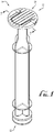
FIGURE 1 is a perspective view of a syringe plunger having a pivoting or hinged pressure flange according to an example embodiment of the present invention, the flange being positioned in a flat or collapsed configuration. -
FIGURE 2 shows the plunger ofFigure 1 , showing the flange positioned in an extended or upright configuration and showing a hook portion being looped through a portion of the flange for hanging the plunger (and syringe). -
FIGURE 3 shows a detailed view of a portion of the plunger ofFigure 2 . -
FIGURE 4 shows a detailed bottom perspective view of a portion of the plunger ofFigure 3 . -
FIGURE 5 shows a cross-sectional view of a portion of the plunger ofFigure 1 taken along line 5-5, showing interengagement of portions of the flange with an end plate of the plunger. -
FIGURE 6 shows a side view of the plunger ofFigures 3-4 , showing the flange positioned in the extended or upright configuration. -
FIGURE 7 shows a side view of the plunger with the flange positioned in a substantially flat or collapsed configuration, showing a hinge thereof being at least partially flexed. -
FIGURE 8 shows a side view of the plunger ofFigure 1 , showing the flange being positioned in a substantially flat or collapsed configuration wherein the hinge connecting the flange to the plunger is substantially unflexed and planar. -
FIGURE 9 shows a front perspective view of a syringe plunger having a pivoting or hinged pressure flange according to another example embodiment of the present invention, the flange being positioned in an extended or upright configuration. -
FIGURE 10 shows a rear perspective view of the syringe plunger ofFigure 9 , the flange being in a flat or collapsed configuration. -
FIGURE 11 shows a rear perspective view ofa portion of the syringe plunger ofFigure 9 . -
FIGURE 12 shows a perspective view of a syringe plunger having a pivoting or hinged pressure flange according to another example embodiment of the present invention, the flange being positioned in an extended or upright configuration. -
FIGURE 13 shows a rear perspective view of the syringe plunger ofFigure 12 , and showing the flange being positioned in a flat or collapsed configuration. -
FIGURE 14 shows the syringe plunger ofFigure 13 , showing the flange being positioned in an extended or upright configuration. -
FIGURE 15 shows a syringe plunger having an opening or engagement portion according to an example which does not embody the present invention. -
FIGURE 16 shows a detailed perspective view of the plunger ofFigure 15 . -
FIGURE 17 shows a syringe comprising the plunger ofFigure 1 movably mounted therein, and showing the syringe and plunger being engaged with a syringe pump according to an example embodiment of the present invention. -
FIGURE 18 shows a syringe comprising the plunger ofFigure 2 , and showing the flange thereof in an extended or upright configuration whereby a hook or other support engages the flange to suspend the syringe for use as a gravity feed system. -
FIGURE 19 shows a syringe comprising the plunger ofFigure 1 , and showing a user manually operating the plunger by depressing the pressure plate with the hinged flange in a flat or collapsed configuration. -
FIGURE 20 shows a syringe plunger having a contact face according to an example which does not embody the present invention. - The present invention may be understood more readily by reference to the following detailed description of the invention taken in connection with the accompanying drawing figures, which form a part of this disclosure. It is to be understood that this invention is not limited to the specific devices, methods, conditions or parameters described and/or shown herein, and that the terminology used herein is for the purpose of describing particular embodiments by way of example only and is not intended to be limiting of the claimed invention.
- Also, as used in the specification including the appended claims, the singular forms "a," "an," and "the" include the plural, and reference to a particular numerical value includes at least that particular value, unless the context clearly dictates otherwise. Ranges may be expressed herein as from "about" or "approximately" one particular value and/or to "about" or "approximately" another particular value. When such a range is expressed, another embodiment includes from the one particular value and/or to the other particular value. Similarly, when values are expressed as approximations, by use of the antecedent "about," it will be understood that the particular value forms another embodiment.
- With reference now to the drawing figures, wherein like reference numbers represent corresponding parts throughout the several views,
Figures 1-8 show a syringe plunger 10 according to an example embodiment of the present invention. In example forms, theplunger 10 is configured for sealingly engaging the interior containment cavity of a syringe barrel or body, for example, wherein advancement or retraction of theplunger 10 within the cavity of the syringe barrel varies the contained volume of the syringe to discharge or fill the syringe with fluid contents such as fluids for enteral delivery. - According to example forms, the syringe is optionally a vented syringe, having one or more vents allowing fluid passage between the syringe barrel and plunger, such that the plunger is movable between a vented position and a sealed/vacuum position.
U.S. Published Patent Application Serial No. 13/231,185 , Patent Application Publication No.US 2012/0071853 ;U.S. Published Patent Application Serial No. 14/224,297 , Patent Application Publication No.US 2014/0207098 ; andU.S. Published Patent Application Serial No. 14/614,156 , Patent Application Publication No.US 2015/0148753 show example vented syringes for use with gravity feed systems, the vented syringe barrels of which may be adapted to receive a syringe plunger having a hinged pressure flange according to example embodiments of the present invention. - In example embodiments, the
syringe plunger 10 comprises a first ordistal end 12 and a second orproximal end 14. Thedistal end 12 comprises a sealinghead 16 for tightly engaging an innerwall of a cavity of a syringe body with a fluid tight seal, and theproximal end 14 comprises a pressure plate, thumb pad orcontact face 20 to engage a depressor of a syringe pump (or permit user manipulation by hand operation). Amain body portion 22 of theplunger 10 generally connects thefirst end 12 to thesecond end 14. In example forms, themain body portion 22 generally comprises one or moreplanar ribs 24 connecting the sealinghead 16 to thecontact face 20. In one form, themain body portion 22 comprises generallyuniform ribs 24 having a cruciform cross-section in the shape of a plus (+) sign. Optionally, cross-sections of other desired shapes and configurations can be chosen as desired. As shown inFigure 2 and according to example embodiments, thecontact face 20 of thesyringe plunger 10 comprises a fixedportion 30 and a hinged orflange portion 50 generally mounted to move relative to the fixedportion 30. As depicted inFigure 1 , theribs 24 can comprise one or more cutouts, which reduce the overall diameter of the ribs to a size for engagement with the fixedportion 30 of thecontact face 20. Furthermore, one or more discs or supports 26 can be formed with one or more of theribs 24 along the length of themain body portion 22 for providing additional support. - As depicted in
Figures 1-4 , theflange portion 50 of thecontact face 20 of thesyringe plunger 10 is generally hinged to pivot relative to two generally symmetrical wings orarms 32 extending from opposite sides of the fixedportion 30. According to one example form, thecontact face 20 of theplunger 10 is generally disc-shaped or generally circular whereby the fixedportion 30 is generally T-shaped and theflange portion 50 is generally U-shaped, for example, wherein the ends of theU-shaped flange portion 50 are pivotally or hingedly mounted to upper horizontal ends 34 of the T-shaped fixed portion 30 (e.g., the arms 32), such that in a retracted or collapsed configuration (seeFigure 1 ) a central member orportion 40 of the T-shaped fixedportion 30 can be received in an 56 opening of theU-shaped flange portion 50 to form a generally flat anduniform contact face 20 adapted for manipulation by a user or a syringe pump. - In example embodiments, a living
hinge 60 is provided between the fixed andflange portions syringe plunger 10 such that the two portions are generally integrally formed together with a thin web of flexible material extending therebetween, allowing for hinged movement of theflange portion 50 relative to the fixedportion 30, for example, between a closed, flat, collapsed or retracted position (seeFigure 1 ), and an open, expanded, extended or upright configuration (seeFigures 2-4 ) for allowing a hook (e.g., IV hook) or other engagement member to extend through an opening formed in the flange portion for hanging the syringe and plunger in a substantially vertical orientation, for example, wherein the plunger is moved to a vented position to permit discharge of the fluid therein within a feeding tube and to the patient (seeFigure 18 ). For example, according to example embodiments, the livinghinge 60 is generally integrally connected between the upper horizontal ends 34 of the fixed portion 30 (seeFigure 3 ) and hinge connection faces 62 defined at the ends of thearms 52 of the flange portion 50 (seeFigure 4 ). Optionally, the livinghinge 60 can be provided on other portions of the fixed andflange portions flange portion 50 relative to the fixedportion 30 between the collapsed configuration (seeFigures 5 and8 ) and the upright configuration. - According to example embodiments, the
flange portion 50 comprises two end extensions orarms 52 that are generally offset from one another and a middle section orcentral connection portion 54 connecting together top portions of the twoarms 52, for example, to form a generally upside-down U-shaped member. In example forms, the contact face orpressure plate 20 is generally circular in shape, and thus, themiddle section 54 and outer portions of thearms 52 are generally arcuate or radiused to match the profile of the contact face. As depicted inFigures 4-5 , theflange portion 50 comprises at least one engagement or coupling feature for providing coupling engagement with a portion of the fixed member, for example, when the flexible member is moved to the collapsed configuration such thatupper surfaces flange portions ledge 64 is provided along interior portions of thearms 52 for providing removable engagement with portions of the fixed portion. - In example embodiments, opposite sides of the
central member 40 of the fixedportion 30 comprisechannels 42 for receiving and providing coupling interengagement with theledges 64 of thearms 52 of theflange portion 50. Generally, the features of the upper surfaces of the fixed and flange portions are matching such that in the retracted configuration the contact face is completed and can be used normally (e.g., for compressing in a pump or grasping for moving the plunger relative to the syringe barrel). In example embodiments, the upper surfaces of the fixed andflange portions portion 30 comprises one or more surface features 47 and the flange portion comprises surface features 72. Optionally, other surface features can be provided as desired. - In example embodiments, as shown in
Figures 6-8 , moving the flange portion to a retracted or closed position causes theflange portion 50 to become engaged with the fixedportion 30 such that theflange portion 50 is mounted at a position relative to the fixed portion to cause upward bulging or outwardly bowing of the living hinges 60 for example, such that the flange portion is generally positioned at least partially closer than the extension of the flange portion (seeFigure 7 ). As shown inFigures 7-8 , a user or feed pump may apply a force to thecontact face 20 to move theflange portion 50 outwardly relative to the fixedportion 30. In example embodiments, ends 36 of thearms 32 of the fixedportion 30 relative to ends of thearms 62 of theflange portion 50 comprises a length X of between about 0.1 to about 1 millimeters, more preferably between about 0.2 to about 0.8 millimeters, for example about 0.6 millimeters according to example embodiments. As desired, a user can move the flange portion from a closed position to an open position by pushing upwards on at least a portion of the flange portion while holding the fixed portion and/or the main body portion of the syringe plunger. In example embodiments, thecontact face 20 comprises a thickness T of between about 1.50 - 2.50 millimeters, for example between about 2.00 - 2.25 millimeters according to an example embodiment of the present invention. Optionally, other thicknesses T can be provided as desired. - Referring back to
Figure 6 , theflange portion 50 is in the upright configuration withflange portion 50 generally extending at an angle α relative to the fixedportion 30, for example, wherein α is generally between about 25 - 165 degrees, more particularly for example between about 45 - 135 degrees, for example about 90 degrees according to example embodiments. In example embodiments, theplunger 10 is formed by injection molding whereby theflange portion 50 is molded in the upright configuration with the angle α being about 90 degrees. Thus, in a relaxed or equilibrium state, theflange portion 50 generally extends at an angle of about 90 degrees relative to an upper surface of the fixed portion. As such, when the plunger is engaged with a syringe and with the flange portion in the upright configuration, an IV hook or other hook or engagement member can easily engage the flange portion by extending a portion thereof through anopening 56 formed between thearms 52 and thecentral connection portion 54 of theflange portion 50, and theupper surface 46 of the fixed portion 30 (seeFigure 18 ). -
Figures 9-11 show aplunger 100 according to another example embodiment of the present invention. As depicted, theplunger 100 is generally similarto theplunger 10 and comprises a first ordistal end 112 and a second orproximal end 114. Thedistal end 112 comprises a sealinghead 116 for tightly engaging an inner wall of a cavity of a syringe body with a fluid tight seal, and theproximal end 114 comprises a pressure plate, thumb pad orcontact face 120 to engage a depressor of a syringe pump (or permit user manipulation by hand operation). Amain body portion 122 of theplunger 100 generally connects thefirst end 112 to thesecond end 114. In example forms, themain body portion 122 generally comprises one or moreplanar ribs 124 connecting the sealinghead 116 to thecontact face 120. - In example embodiments, the
contact face 120 at thesecond end 114 comprises a fixedportion 130 and a hinged hangingflange portion 150 that is movable relative to the fixedportion 130. According to example forms, theflange portion 150 is connected to the fixedportion 130 by a plurality resiliently flexible living hinges 164, for example, about 9 separate hinges. Optionally, more or less hinges can be provided as desired. In example embodiments, the fixedportion 130 generally comprises a portion of a complete disc-shaped contact face, and theflange portion 150 comprises the other portion of the complete disc-shaped contact face, and wherein the flexible living hinges 164 generally extend between anend face 134 of the fixedportion 130 and anend face 166 of theflange portion 150, for example, such that theflange portion 150 is movable between the collapsed configuration (Figure 10 ) and the upright configuration (Figures 9 and11 ). - As shown in
Figure 11 , the fixedportion 130 comprises at least one interengagement feature 136 for coupling theflange portion 150 in the collapsed configuration, for example, such that thepressure plate 120 can be compatible for engagement with a syringe pump or for being pressed by a user's thumb (seeFigures 17- 19). In example embodiments, theinterengagement feature 136 comprises aplatform 140 having a pair ofengagement fingers 142 extending outwardly from theend face 134 of the fixed portion 130 (and thefingers 142 being generally laterally offset from the platform 140) for being received within a pair of spaced-apart channels orreceivers 162 formed in theflange portion 150. In example embodiments, thereceivers 162 comprise end engagement surfaces 163 for providing engagement with thefingers 142. For example, in example embodiments, thefingers 142 compriseend surfaces 143 for engaging the end engagement surfaces 163 of thereceivers 162 when theflange portion 150 is in the collapsed configuration. Furthermore, when theflange portion 150 is in the collapsed configuration and the end surfaces 143 of thefingers 142 are engaging the end engagement surfaces 163 of theflange portion 150, alower surface 156 of theflange portion 150 generally contacts theplatform 140. In example embodiments, theupper surfaces flange portions fingers 142 extending from the fixedportion 130 are generally extensions of two of the surface features 146. According to example embodiments, thefingers 142 generally extend a length such that there is at least some interference of the end surfaces 143 and the end engagement surfaces 163. Optionally, other engagement or coupling features can be provided for coupling theflange portion 130 in the collapsed configuration. - In example embodiments,
flange portion 130 can comprise one or more holes, slots orother openings 160 formed therein for receiving an IV hook or other engagement member for suspending the plunger and an attached syringe. In the depicted embodiment shown inFigure 11 , theflange portion 150 generally comprises a circular opening formed through theflange portion 150, for example, about at a midpoint defined therebetweeen. Alternatively, theopening 160 can be other shapes including polygonal, oval, or other shapes as desired. -
Figures 12-14 show asyringe plunger 200 according to another example embodiment of the present invention. As depicted and similarly described above, thecontact face 220 is generally disc-shaped and comprises a fixedportion 230 and aflange portion 250, and wherein theflange portion 250 is generally movably mounted to pivot relative to a portion of the fixedportion 230 about alinear pivot edge 232. According to example embodiments, asingle living hinge 264 pivotally joins theflange portion 250 to the fixedportion 230 across the width of thecontact face 220 of the syringe plunger. In example embodiments, a pair of generally elongate andradiused protrusions 262 of the flange portion are configured for coupling interengagement withengagement receivers 240 of aplatform 236 of the fixedportion 130. In example embodiments, thereceivers 240 and theprotrusions 262 are generally complementary in shape, for example, to provide for fitting interengagement therebetween. In example embodiments, the coupling engagement of thereceivers 240 andprotrusions 262 is such that at least some interference if provided therebetween, for example to ensure some amount of frictional engagement therebetween generally keeps theflange portion 150 in the collapsed configuration. To move the flange portion to the upright configuration, the user uses a finger or other tool to lift the flange portion relative to the fixed portion. In example embodiments, anend portion 238 of theplatform 236 comprises a larger radiused cutout (defined between the two engagement receivers 240) such that a portion of theflange portion 250 overhangs theplatform 136 and beyond theend portion 238. Thus, a finger, tool or other device can engage only a portion of theflange portion 250 to move theflange portion 250 from the collapsed configuration to the upright configuration. As similarly described above, an opening can be formed through theflange portion 250 for receiving an IV hook or other hanging support. In example forms, the top surfaces of the fixed portion and the flange portion comprise an array of protrudingribs -
Figures 15-16 show aplunger 300 according to an example which does embody the present invention. As depicted, theplunger 300 is generally similar to theplungers distal end 312 and a second orproximal end 314. Thedistal end 312 comprises a sealinghead 316 for tightly engaging an inner wall of a cavity of a syringe body with a fluid tight seal, and theproximal end 314 comprises acontact face 320 to engage a depressor of a syringe pump or permit user manipulation by hand operation. Amain body portion 322 of theplunger 300 generally connects thefirst end 312 to thesecond end 314. In example forms, themain body portion 322 generally comprises one or moreplanar ribs 324 connecting the sealinghead 316 to thecontact face 320. Anengagement feature 330 comprising a U-shaped connector or spaced-apartarms 332 connect themain body portion 322 to thecontact face 320. At least one pass-through oropening 334 is formed within theengagement feature 330 such that an IV hook or other hanging support can engage therewith for hanging the plunger (and syringe attached thereto). Thecontact face 320 is generally circular in shape and comprises a generally planar upper surface 340 having a plurality of spaced-apart ribs 342 protruding from the upper surface 340 thereof. - In use, the hinged portion of the contact flange of the syringe plunger is positioned in its flat or retracted position for use with a syringe S when using a syringe pump SP or for manual actuation of the syringe (see
Figures 17 and19 ). In example embodiments, the syringe S comprises a female connector FC (seeFigures 18-19 ) in the form of an ENFit compatible connector or coupling, for example, which can be connected with another ENFit compatible coupling (which can be connected to a feeding tube FT). In example embodiments, one or more syringe pump clamps C preferably engage the contact flange of the plunger to retain the contact flange up against the driving arm of the pump. As recited above, the thickness T of the contact flange is preferably between about 2 - 2.25 millimeters, for example, which provides a sufficient thickness for accommodating engagement with the syringe pump clamps C. Alternatively, the hinged portion of the contact flange of the syringe plunger is positioned in its upright or extended position for hanging a syringe S in gravity-feed applications, with an IV hook or other hanging support H extending through the opening in the hinged portion of the contact flange to hang the syringe (seeFigure 18 ). As described above according to some example embodiments, the syringe S comprises one or more vents V, for example, to utilize the syringe assembly in a gravity-feed system. Further, the vented syringe and plunger of the present invention can be used for manual manipulation or mounted for use with a syringe pump SP. - According to one example form, the packaged plunger (e.g., before being opened by an end user) is generally configured such that the hinged portion is in its flat or retracted position. According to example embodiments, for example in the case when the plunger is molded with the hinged portion in the upright or extended position, the home position of the hinged flange is generally in the flat, retracted position, for example, which can be manipulated with one or more fingers or thumb, and for compatible use with a metering pump. According to some example embodiments, after the manufacture thereof for example in the case where the plunger is plastic injection molded with the flange being in the upright configuration, one or more of the molded plungers can be directed to an assembly line or feeding machine whereby one or more machines and/or operators move the flange portion from the upright configuration to the collapsed configuration, for example, such that the plunger, when assembled individually or with the syringe, is packaged with the flange in the collapsed configuration. Alternatively, in the case where the plunger is assembled with the syringe prior to packaging of the assembly, the plunger with the flange in the upright configuration can be assembled with the syringe and then the assembly can be moved through an automated process whereby a portion of the syringe is captured by a machine or fixture which in turn performs one or more steps to move the flange portion of the contact face from the upright configuration to the collapsed configuration. Optionally, an individual can grab the assembled syringe and plunger and manually move the flange portion from the upright configuration to the collapsed configuration.
-
Figure 20 shows aplunger 400 according to an example which does not embody the present invention. As depicted, theplunger 400 comprises acontact face 420 comprising anupper surface 422 and optionally having a plurality of raised projections or other surface features, for example, as described above with respect to embodiments of the invention. Thecontact face 420 is generally a one piece circular disc having one ormore openings 430 extending through the entirety of thecontact face 420, for example such that an IV hook or other hanging support H can extend through at least one of theopenings 430 to provide for suspending or hanging of the syringe plunger 400 (and syringe barrel S connected with the plunger 400). The openings are generally circular in shape and sized for compatibility with the support H. Optionally, openings of other shapes and sizes can be provided as desired. One of the openings can be shaped and sized for compatibility with a first support type, hanger or feature, and the other openings can be sized and shaped for compatibility with another support type, hanger or feature, for example, wherein multiple supportive features can be used to hang the syringe therefrom. Optionally, the one or more openings can be sized and shaped for compatibility with a range of supports is various sizes and shapes. - While the invention has been described with reference to preferred and example embodiments, it will be understood by those skilled in the art that a variety of modifications, additions and deletions are within the scope of the invention, as defined by the following claims.
Claims (14)
- A syringe plunger (10) for movably mounting within a syringe barrel (S), the syringe plunger comprising a proximal end with a contact face (20), characterized in that the contact face comprises a hinged portion (50) and a fixed portion (30), wherein the hinged portion is pivotally coupled to the fixed portion and movable between an open configuration and a closed configuration, wherein in the open configuration an opening is accessible for receiving a hanging support member and wherein in the closed configuration the hinged portion is generally planar with respect to the fixed portion.
- The syringe plunger of Claim 1, wherein the contact face (20) is generally circular in shape.
- The syringe plunger of Claim 1 or 2, wherein the contact face (20) comprises a thickness of between about 2.00 - 2.25 millimeters.
- The syringe plunger of any preceding Claim, wherein in the closed configuration the contact face (20) is compatible for both manual manipulation and engagement and use with a syringe pump.
- The syringe plunger of any preceding Claim, wherein the plunger comprises a first end (12) and a second end (14), and a middle body portion (22) extending between the first and second ends, wherein a sealing head (16) is provided at the first end and the contact face is provided at the second end, wherein the fixed portion is mounted to the middle body portion and the hinged portion is mounted to the fixed portion, wherein the opening is formed in the hinged portion.
- The syringe plunger of any preceding Claim, wherein at least one living hinge connects the hinged portion to the fixed portion.
- The syringe plunger of Claim 6, wherein the at least one living hinge integrally connects the hinged portion to the fixed portion.
- The syringe plunger of any preceding Claim, wherein in the open configuration the flange portion is generally oriented perpendicular relative to the fixed portion.
- The syringe plunger of any preceding Claim, wherein the fixed portion comprises a pair of arms and a central member and wherein the hinged portion comprises a U-shaped portion comprising end extensions and a central connection portion.
- The syringe plunger of Claim 9, wherein each of the end extensions are movably mounted to the arms of the fixed portion by a living hinge.
- The syringe plunger of Claim 10, wherein the hinged portion comprises a central aperture defined between the end extensions and the central connection member for receiving the hanging support member.
- A syringe comprising a syringe barrel (S) and the syringe plunger (10) of any preceding Claim adapted to advance and retract within the syringe barrel.
- The syringe of Claim 12, wherein the syringe comprises at least one vent and an ENFit compatible coupling.
- The syringe of Claim 13, wherein the ENFit compatible coupling comprises a female connector.
Applications Claiming Priority (2)
| Application Number | Priority Date | Filing Date | Title |
|---|---|---|---|
| US201662299604P | 2016-02-25 | 2016-02-25 | |
| PCT/US2017/018957 WO2017147192A1 (en) | 2016-02-25 | 2017-02-22 | Syringe plunger with hinged flange |
Publications (2)
| Publication Number | Publication Date |
|---|---|
| EP3419696A1 EP3419696A1 (en) | 2019-01-02 |
| EP3419696B1 true EP3419696B1 (en) | 2020-09-09 |
Family
ID=58231741
Family Applications (1)
| Application Number | Title | Priority Date | Filing Date |
|---|---|---|---|
| EP17709267.3A Not-in-force EP3419696B1 (en) | 2016-02-25 | 2017-02-22 | Syringe plunger with hinged flange |
Country Status (4)
| Country | Link |
|---|---|
| US (2) | US10722432B2 (en) |
| EP (1) | EP3419696B1 (en) |
| CA (1) | CA3015874A1 (en) |
| WO (1) | WO2017147192A1 (en) |
Families Citing this family (7)
| Publication number | Priority date | Publication date | Assignee | Title |
|---|---|---|---|---|
| US11173248B2 (en) * | 2018-04-23 | 2021-11-16 | Kellida Inc. | Method and system for operating a plunger |
| US11998723B2 (en) | 2019-02-26 | 2024-06-04 | Becton, Dickinson & Company | Vented syringe |
| US11833340B2 (en) * | 2019-02-27 | 2023-12-05 | Born Life Hacks, LLC | Syringe and plunger clip for bottles |
| USD911519S1 (en) * | 2019-05-29 | 2021-02-23 | Radiometer Medical Aps | Syringe plunger |
| US20210093788A1 (en) * | 2019-09-29 | 2021-04-01 | F3 Biodesigns, Llc | Enteral feeding device and method of using the same |
| USD956205S1 (en) * | 2020-11-24 | 2022-06-28 | Takeda Pharmaceutical Company Limited | Pusher foot for a fluid delivery device |
| USD1056204S1 (en) * | 2022-05-25 | 2024-12-31 | Dna Genotek Inc. | Floater for a liquid collection device |
Family Cites Families (114)
| Publication number | Priority date | Publication date | Assignee | Title |
|---|---|---|---|---|
| US2051940A (en) * | 1934-08-15 | 1936-08-25 | Chichester-Mi Herbert G Wright | Bucket and pail |
| US3026872A (en) * | 1952-05-17 | 1962-03-27 | American Cyanamid Co | Hypodermic syringe |
| FR1126718A (en) | 1955-06-25 | 1956-11-29 | Maintained Orientation Syringe | |
| US3113873A (en) | 1961-09-01 | 1963-12-10 | Anaconda Aluminum Co | Food package |
| US3119541A (en) * | 1961-12-28 | 1964-01-28 | Celluplastics Inc | Hanging cap and container combination |
| US3341047A (en) * | 1966-05-10 | 1967-09-12 | Abbott Lab | Container and bail construction |
| US3581928A (en) * | 1968-10-14 | 1971-06-01 | American Hospital Supply Corp | Hanger construction for medical liquid container |
| DE2108381C3 (en) | 1971-01-29 | 1982-01-28 | Arthur 7530 Pforzheim Doller | Injection or suction ampoule |
| US3731684A (en) | 1971-04-08 | 1973-05-08 | Cenco Medical Health Supply Co | Closed irrigation and urinary drainage system apparatus |
| SE380975B (en) * | 1973-03-08 | 1975-11-24 | S Arlers | Syringe |
| US3885562A (en) | 1973-11-16 | 1975-05-27 | John C Lampkin | Syringe with writing surface |
| US3900184A (en) | 1973-12-13 | 1975-08-19 | Burron Medical Prod Inc | Roller clamp for tubing |
| US3880311A (en) | 1974-02-26 | 1975-04-29 | American Hospital Supply Corp | Collapsible medical liquid bottle with calibration and label orienting hanger structure |
| US4153056A (en) * | 1977-06-16 | 1979-05-08 | Jules Silver | Syringe with removable length adjusting member |
| US4356824A (en) | 1980-07-30 | 1982-11-02 | Vazquez Richard M | Multiple lumen gastrostomy tube |
| USD267536S (en) | 1980-11-10 | 1983-01-11 | Impact Products, Inc. | Combined scoop, funnel, and pourer |
| US4460143A (en) * | 1981-04-23 | 1984-07-17 | Fujisawa Pharmaceutical Co., Ltd. | Vial suspender |
| US4392851A (en) | 1981-11-23 | 1983-07-12 | Abbott Laboratories | In-line transfer unit |
| US4413741A (en) * | 1981-12-16 | 1983-11-08 | Baxter Travenol Laboratories, Inc. | Hanger assembly for bottles |
| USD282962S (en) | 1983-02-14 | 1986-03-11 | Gerber Albert J | Plastic tubing connector |
| USD282807S (en) | 1984-03-02 | 1986-03-04 | Hasse Patricia W | Guard funnel |
| USD288667S (en) * | 1984-07-11 | 1987-03-10 | Miner Container Printing, Inc. | Container closure |
| US4886495A (en) * | 1987-07-08 | 1989-12-12 | Duoject Medical Systems Inc. | Vial-based prefilled syringe system for one or two component medicaments |
| USD307795S (en) | 1987-06-16 | 1990-05-08 | Frantz Medical Development Ltd. | Combined disposable medical pump cassette and connectors for enteral fluid delivery pump systems |
| US4994048A (en) | 1988-09-19 | 1991-02-19 | Becton, Dickinson And Company | Apparatus and method for connecting a passageway and openings with a connector |
| USD330862S (en) | 1990-07-20 | 1992-11-10 | Charles Shibley | Combined formula mixer and container |
| US5137527A (en) | 1990-09-20 | 1992-08-11 | Clintec Nutrition Co. | Enteral-specific spike/bag port system |
| DE4032761A1 (en) | 1990-10-16 | 1992-04-23 | Schuckmann Alfred Von | CARTRIDGE FOR USE IN DISPENSER |
| USD332379S (en) * | 1991-12-09 | 1993-01-12 | Rubbermaid Incorporated | Lid for storage jar with handle |
| US5202533A (en) | 1992-01-28 | 1993-04-13 | Vandersteen Douglas G A | Drug injection apparatus for an animal |
| US5232112A (en) * | 1992-04-13 | 1993-08-03 | Ruco Products, Inc. | Molded lid for receiving handle |
| US5244113A (en) * | 1992-08-24 | 1993-09-14 | Northwestern Bottle Company | Container lid assembly |
| US5279566A (en) | 1992-12-23 | 1994-01-18 | Ronald S. Kline | Protective assembly for hypodermic syringes |
| US5460603A (en) | 1993-04-08 | 1995-10-24 | Massachusetts Institute Of Technology | Method and apparatus for preventing back flow in gastroenterological feeding system |
| US5832971A (en) | 1994-05-19 | 1998-11-10 | Becton, Dickinson And Company | Syringe filling and delivery device |
| US5746733A (en) | 1994-05-19 | 1998-05-05 | Becton, Dickinson And Company | Syringe filling and delivery device |
| US5611787A (en) | 1994-10-13 | 1997-03-18 | Methodist Hospital Of Indiana, Inc. | Method and device for gastric line insertion |
| US5549550A (en) | 1995-01-13 | 1996-08-27 | Abbott Laboratories | Method of adding marker dye to nutritional product during enteral tube feeding |
| US6036669A (en) | 1995-01-13 | 2000-03-14 | Abbott Laboratories | Apparatus for altering composition of nutritional product during enteral tube feeding |
| US5531682A (en) | 1995-01-13 | 1996-07-02 | Abbott Laboratories | Apparatus for adding marker dye to nutritional product during enternal tube feeding |
| US6277092B1 (en) | 1995-01-13 | 2001-08-21 | Abbott Laboratories | Apparatus for altering composition of nutritional product during enteral tube feeding |
| US5779668A (en) | 1995-03-29 | 1998-07-14 | Abbott Laboratories | Syringe barrel for lyophilization, reconstitution and administration |
| DE29617949U1 (en) | 1996-10-01 | 1997-04-30 | Schulz, Klaus, Dr.med., 50259 Pulheim | Syringe with a closable venting channel or venting gap |
| US5843042A (en) | 1996-11-06 | 1998-12-01 | Ren; Liang Chen | Oral medicine dispensing device having a metered syringe component and reservoir |
| US6029946A (en) | 1997-09-15 | 2000-02-29 | Tiva Medical Inc. | Needleless valve |
| US6019747A (en) | 1997-10-21 | 2000-02-01 | I-Flow Corporation | Spring-actuated infusion syringe |
| US6065649A (en) * | 1997-10-23 | 2000-05-23 | Scoggins; Lester E. | Dispensing container with top and bottom access ports and a dispensing manifold therefore |
| USD447797S1 (en) | 1998-10-13 | 2001-09-11 | Becton, Dickinson And Company | Syringe |
| US6245046B1 (en) | 1999-05-03 | 2001-06-12 | University Of New Mexico | Reciprocating syringes |
| IT1308678B1 (en) | 1999-12-21 | 2002-01-09 | Cane Srl | SYRINGE FOR INFUSION OF DRUGS. |
| JP4558130B2 (en) * | 2000-03-17 | 2010-10-06 | 株式会社トップ | Syringe |
| US6482170B1 (en) | 2000-09-18 | 2002-11-19 | Corpak, Inc. | Apparatus and method for relieving gastric pressure during enteral feeding |
| USD461243S1 (en) | 2000-12-04 | 2002-08-06 | Bracco Diagnostics Inc. | Ellipsoidal syringe barrel |
| JP2003088532A (en) | 2001-09-19 | 2003-03-25 | Olympus Optical Co Ltd | Operation instrument |
| US6752790B2 (en) | 2002-02-27 | 2004-06-22 | Karla Coombs | Dosage vessel for use with an indwelling feeding tube |
| USD474115S1 (en) * | 2002-03-20 | 2003-05-06 | Masterchem Industries, Inc. | Container |
| US6766917B1 (en) * | 2002-09-11 | 2004-07-27 | Blewitt, Iii John J. | Closure with hinged hook |
| US20040054350A1 (en) | 2002-09-17 | 2004-03-18 | Shaughnessy Michael C. | Enteral feeding unit having a reflux device and reflux method |
| USD511457S1 (en) * | 2004-01-29 | 2005-11-15 | Drug Plastics & Glass Company, Inc. | Container closure with handle |
| DE102004023078B3 (en) | 2004-05-11 | 2006-01-19 | Fresenius Kabi Deutschland Gmbh | Probe for enteral nutrition and probe system for enteral nutrition and gastric decompression or drainage |
| US20060264824A1 (en) | 2005-05-20 | 2006-11-23 | Swisher Kyle Y Iii | Disposable safety medical syringe assembly and method of manufacture |
| US7921847B2 (en) | 2005-07-25 | 2011-04-12 | Intubix, Llc | Device and method for placing within a patient an enteral tube after endotracheal intubation |
| US20070060898A1 (en) | 2005-09-07 | 2007-03-15 | Shaughnessy Michael C | Enteral medical treatment assembly having a safeguard against erroneous connection with an intravascular treatment system |
| US7846131B2 (en) | 2005-09-30 | 2010-12-07 | Covidien Ag | Administration feeding set and flow control apparatus with secure loading features |
| US20070123822A1 (en) | 2005-11-25 | 2007-05-31 | Biotop Holding Co., Ltd. | Safety syringe for taking blood |
| US20070265579A1 (en) | 2006-05-10 | 2007-11-15 | Gennady Kleyman | Dental syringe |
| WO2007095541A2 (en) | 2006-02-13 | 2007-08-23 | Gerald Moss | Plural lumen gastrostomy tube insert for placement into the duodenum and method of monitoring and managing feeding |
| USD578210S1 (en) | 2006-03-14 | 2008-10-07 | Hisamitsu Pharmaceutical Co., Inc. | Injector |
| US7955315B2 (en) | 2006-07-24 | 2011-06-07 | Ethicon, Inc. | Articulating laparoscopic device and method for delivery of medical fluid |
| US8540683B2 (en) | 2006-10-09 | 2013-09-24 | Acist Medical Systems, Inc. | Syringe device and injector system including a vent for relieving a vacuum within a syringe |
| US7560686B2 (en) | 2006-12-11 | 2009-07-14 | Tyco Healthcare Group Lp | Pump set and pump with electromagnetic radiation operated interlock |
| USD552773S1 (en) | 2006-12-20 | 2007-10-09 | Yafa Pen Company | Syringe flashlight |
| US20080183153A1 (en) | 2007-01-31 | 2008-07-31 | Benlan, Inc. | Enteral Feeding Tube Connector |
| US7842217B2 (en) | 2007-03-28 | 2010-11-30 | Benlan, Inc. | Enteral-only syringe and method of manufacturing same |
| WO2008124737A2 (en) | 2007-04-10 | 2008-10-16 | Mdesign International | Percutaneous delivery and retrieval systems for shape-changing orthopedic joint devices |
| EP1980282A1 (en) | 2007-04-10 | 2008-10-15 | F.Hoffmann-La Roche Ag | Medicine reservoir and device for automatic dispensing of a liquid medicine |
| US8034033B2 (en) | 2007-04-13 | 2011-10-11 | Yair Grinberg | Hypodermic syringe with vial attachment |
| US11191931B2 (en) | 2007-10-01 | 2021-12-07 | Pmt Partners, Llc | Methods for manually injecting/aspirating fluids through small diameter catheters and needles and manual injection/aspiration systems including small diameter catheters and needles |
| US7980131B2 (en) | 2008-01-07 | 2011-07-19 | Jody Barton | Bottomless measuring cup |
| US8162916B2 (en) | 2008-02-08 | 2012-04-24 | Codan Us Corporation | Enteral feeding safety reservoir and system |
| US8231597B2 (en) | 2008-02-08 | 2012-07-31 | Codan Us Corporation | Enteral feeding safety reservoir and system |
| US8366697B2 (en) | 2008-02-08 | 2013-02-05 | Codan Us Corporation | Enteral feeding safety reservoir and system |
| US20090287161A1 (en) | 2008-05-15 | 2009-11-19 | Allergan, Inc | Metered, multiple dose/aliquot syringe |
| WO2009141510A1 (en) | 2008-05-20 | 2009-11-26 | Sannier Gerard | Gel dispenser |
| DE102008035835B4 (en) | 2008-08-02 | 2015-02-19 | Walter Pobitschka | Method and device for transferring a substance between closed systems |
| EP2345441B1 (en) * | 2008-10-06 | 2018-11-21 | Terumo Kabushiki Kaisha | Syringe pump |
| WO2010054290A1 (en) | 2008-11-10 | 2010-05-14 | Delphi Technologies, Inc. | Syringe hanger |
| USD618347S1 (en) | 2009-06-04 | 2010-06-22 | Cynthia Bradshaw | Applicator suppository injector |
| US8715244B2 (en) | 2009-07-07 | 2014-05-06 | C. R. Bard, Inc. | Extensible internal bolster for a medical device |
| AU2010286385A1 (en) | 2009-08-24 | 2012-03-15 | Clinton Frederick Shahim | Closed wound drainage system |
| USD635249S1 (en) | 2009-11-10 | 2011-03-29 | Bruce Becker | Syringe |
| USD632144S1 (en) | 2009-11-19 | 2011-02-08 | Weisenbach Specialty Printing, Inc. | Spout |
| US20110270227A1 (en) | 2010-04-30 | 2011-11-03 | Baxa Corporation | Method and apparatus for the enteral dispensation of liquid medications |
| US9433562B2 (en) | 2010-07-27 | 2016-09-06 | Neomed, Inc. | System for aseptic collection and enteral delivery |
| USD654585S1 (en) | 2010-12-02 | 2012-02-21 | Neomed, Inc. | Enteral syringe |
| US8992488B2 (en) * | 2010-09-14 | 2015-03-31 | Neomed, Inc. | Enteral syringe |
| US9433729B2 (en) | 2010-09-14 | 2016-09-06 | Neomed, Inc. | Enteral syringe |
| USD654584S1 (en) | 2010-09-14 | 2012-02-21 | Neomed, Inc. | Enteral syringe |
| USD646531S1 (en) | 2010-09-25 | 2011-10-11 | Murphy Trisha A | Funnel measuring cup |
| US8777900B2 (en) | 2010-12-14 | 2014-07-15 | Kimberly-Clark Worldwide, Inc. | Ambulatory enteral feeding system |
| US20120150111A1 (en) | 2010-12-14 | 2012-06-14 | Hershey Adrienne A | Passive Enteral Venting System |
| CA2845392A1 (en) | 2011-09-08 | 2013-03-14 | Sanofi-Aventis Deutschland Gmbh | Securing means for a drug delivery device |
| US9333288B2 (en) | 2011-09-30 | 2016-05-10 | Becton Dickinson France, S.A.S. | Attachable plunger rod and associated packaging |
| US10159796B2 (en) | 2011-09-30 | 2018-12-25 | Becton Dickinson France, S.A.S. | Syringe assembly having a telescoping plunger rod |
| US9067023B2 (en) * | 2011-11-21 | 2015-06-30 | University Of Louisville Research Foundation, Inc. | Ergonomic syringe and adaptor |
| EP2879646A1 (en) | 2012-08-06 | 2015-06-10 | Neomed, Inc. | System and method for metered enteral feeding |
| USD703997S1 (en) * | 2012-09-13 | 2014-05-06 | La Termoplastic F.B.M. S.R.L. | Knob with a movable handle for use on cooking utensils and apparatus |
| US9301587B2 (en) | 2013-01-14 | 2016-04-05 | Stephen D'Amico | Hair color (or dye) storage, dispensing and measurement (or measuring) system |
| USD720218S1 (en) * | 2013-10-15 | 2014-12-30 | Confluence Beverages, LLC | Bottle cap |
| TWI580453B (en) * | 2013-11-26 | 2017-05-01 | 卡貝歐洲有限公司 | Housing blank and activation member blank for a medicament delivery device, a kit comprising such blanks, and a medicament delivery device |
| JP6427919B2 (en) * | 2014-03-31 | 2018-11-28 | 株式会社ジェイ・エム・エス | Syringe |
| USD759500S1 (en) * | 2014-04-28 | 2016-06-21 | Jab Distributors, Llc. | Jar package |
| USD742064S1 (en) * | 2015-06-23 | 2015-10-27 | The Hand Media, Inc. | Personal vaporizer compartment cover |
| USD853182S1 (en) * | 2018-01-12 | 2019-07-09 | Klean Kanteen, Inc. | Beverage container cap |
-
2017
- 2017-02-22 EP EP17709267.3A patent/EP3419696B1/en not_active Not-in-force
- 2017-02-22 WO PCT/US2017/018957 patent/WO2017147192A1/en not_active Ceased
- 2017-02-22 CA CA3015874A patent/CA3015874A1/en active Pending
- 2017-02-22 US US15/439,711 patent/US10722432B2/en active Active
-
2020
- 2020-06-22 US US16/907,777 patent/US11925791B2/en active Active
Non-Patent Citations (1)
| Title |
|---|
| None * |
Also Published As
| Publication number | Publication date |
|---|---|
| EP3419696A1 (en) | 2019-01-02 |
| US20170246087A1 (en) | 2017-08-31 |
| US20200315921A1 (en) | 2020-10-08 |
| US11925791B2 (en) | 2024-03-12 |
| WO2017147192A1 (en) | 2017-08-31 |
| US10722432B2 (en) | 2020-07-28 |
| CA3015874A1 (en) | 2017-08-31 |
Similar Documents
| Publication | Publication Date | Title |
|---|---|---|
| US11925791B2 (en) | Syringe plunger with hinged flange | |
| AU2023203762B2 (en) | Sanitizing caps for medical connectors | |
| US5637099A (en) | Needle handling apparatus and methods | |
| US10016587B2 (en) | Caps for needleless connectors | |
| US4966582A (en) | Injection site platform | |
| EP2616124B1 (en) | Enteral syringe | |
| US20060011506A1 (en) | Packaging for a kit, and related methods of use | |
| CN1392778A (en) | Ear piercing system with hinged hoop earrings | |
| EP2155570A1 (en) | Dual pack container | |
| US9433729B2 (en) | Enteral syringe | |
| EP1061858B1 (en) | Apparatus for the sterile transfer of fluids | |
| CA2929979A1 (en) | Enteral syringe | |
| CN222092259U (en) | Syringes and prefilled flush syringes | |
| JPH0670738U (en) | Infusion container | |
| HK1069744A (en) | Ear piercing systems with hinged hoop earrings | |
| HK1069743A (en) | Ear piercing systems with hinged hoop earrings |
Legal Events
| Date | Code | Title | Description |
|---|---|---|---|
| STAA | Information on the status of an ep patent application or granted ep patent |
Free format text: STATUS: UNKNOWN |
|
| STAA | Information on the status of an ep patent application or granted ep patent |
Free format text: STATUS: THE INTERNATIONAL PUBLICATION HAS BEEN MADE |
|
| PUAI | Public reference made under article 153(3) epc to a published international application that has entered the european phase |
Free format text: ORIGINAL CODE: 0009012 |
|
| STAA | Information on the status of an ep patent application or granted ep patent |
Free format text: STATUS: REQUEST FOR EXAMINATION WAS MADE |
|
| 17P | Request for examination filed |
Effective date: 20180918 |
|
| AK | Designated contracting states |
Kind code of ref document: A1 Designated state(s): AL AT BE BG CH CY CZ DE DK EE ES FI FR GB GR HR HU IE IS IT LI LT LU LV MC MK MT NL NO PL PT RO RS SE SI SK SM TR |
|
| AX | Request for extension of the european patent |
Extension state: BA ME |
|
| DAV | Request for validation of the european patent (deleted) | ||
| DAX | Request for extension of the european patent (deleted) | ||
| GRAP | Despatch of communication of intention to grant a patent |
Free format text: ORIGINAL CODE: EPIDOSNIGR1 |
|
| STAA | Information on the status of an ep patent application or granted ep patent |
Free format text: STATUS: GRANT OF PATENT IS INTENDED |
|
| INTG | Intention to grant announced |
Effective date: 20200415 |
|
| GRAS | Grant fee paid |
Free format text: ORIGINAL CODE: EPIDOSNIGR3 |
|
| GRAA | (expected) grant |
Free format text: ORIGINAL CODE: 0009210 |
|
| STAA | Information on the status of an ep patent application or granted ep patent |
Free format text: STATUS: THE PATENT HAS BEEN GRANTED |
|
| AK | Designated contracting states |
Kind code of ref document: B1 Designated state(s): AL AT BE BG CH CY CZ DE DK EE ES FI FR GB GR HR HU IE IS IT LI LT LU LV MC MK MT NL NO PL PT RO RS SE SI SK SM TR |
|
| REG | Reference to a national code |
Ref country code: GB Ref legal event code: FG4D |
|
| REG | Reference to a national code |
Ref country code: AT Ref legal event code: REF Ref document number: 1310761 Country of ref document: AT Kind code of ref document: T Effective date: 20200915 Ref country code: CH Ref legal event code: EP |
|
| REG | Reference to a national code |
Ref country code: IE Ref legal event code: FG4D |
|
| REG | Reference to a national code |
Ref country code: DE Ref legal event code: R096 Ref document number: 602017023259 Country of ref document: DE |
|
| REG | Reference to a national code |
Ref country code: LT Ref legal event code: MG4D |
|
| PG25 | Lapsed in a contracting state [announced via postgrant information from national office to epo] |
Ref country code: SE Free format text: LAPSE BECAUSE OF FAILURE TO SUBMIT A TRANSLATION OF THE DESCRIPTION OR TO PAY THE FEE WITHIN THE PRESCRIBED TIME-LIMIT Effective date: 20200909 Ref country code: FI Free format text: LAPSE BECAUSE OF FAILURE TO SUBMIT A TRANSLATION OF THE DESCRIPTION OR TO PAY THE FEE WITHIN THE PRESCRIBED TIME-LIMIT Effective date: 20200909 Ref country code: BG Free format text: LAPSE BECAUSE OF FAILURE TO SUBMIT A TRANSLATION OF THE DESCRIPTION OR TO PAY THE FEE WITHIN THE PRESCRIBED TIME-LIMIT Effective date: 20201209 Ref country code: GR Free format text: LAPSE BECAUSE OF FAILURE TO SUBMIT A TRANSLATION OF THE DESCRIPTION OR TO PAY THE FEE WITHIN THE PRESCRIBED TIME-LIMIT Effective date: 20201210 Ref country code: LT Free format text: LAPSE BECAUSE OF FAILURE TO SUBMIT A TRANSLATION OF THE DESCRIPTION OR TO PAY THE FEE WITHIN THE PRESCRIBED TIME-LIMIT Effective date: 20200909 Ref country code: NO Free format text: LAPSE BECAUSE OF FAILURE TO SUBMIT A TRANSLATION OF THE DESCRIPTION OR TO PAY THE FEE WITHIN THE PRESCRIBED TIME-LIMIT Effective date: 20201209 Ref country code: HR Free format text: LAPSE BECAUSE OF FAILURE TO SUBMIT A TRANSLATION OF THE DESCRIPTION OR TO PAY THE FEE WITHIN THE PRESCRIBED TIME-LIMIT Effective date: 20200909 |
|
| REG | Reference to a national code |
Ref country code: AT Ref legal event code: MK05 Ref document number: 1310761 Country of ref document: AT Kind code of ref document: T Effective date: 20200909 |
|
| REG | Reference to a national code |
Ref country code: NL Ref legal event code: MP Effective date: 20200909 |
|
| PG25 | Lapsed in a contracting state [announced via postgrant information from national office to epo] |
Ref country code: PL Free format text: LAPSE BECAUSE OF FAILURE TO SUBMIT A TRANSLATION OF THE DESCRIPTION OR TO PAY THE FEE WITHIN THE PRESCRIBED TIME-LIMIT Effective date: 20200909 Ref country code: RS Free format text: LAPSE BECAUSE OF FAILURE TO SUBMIT A TRANSLATION OF THE DESCRIPTION OR TO PAY THE FEE WITHIN THE PRESCRIBED TIME-LIMIT Effective date: 20200909 Ref country code: LV Free format text: LAPSE BECAUSE OF FAILURE TO SUBMIT A TRANSLATION OF THE DESCRIPTION OR TO PAY THE FEE WITHIN THE PRESCRIBED TIME-LIMIT Effective date: 20200909 |
|
| PG25 | Lapsed in a contracting state [announced via postgrant information from national office to epo] |
Ref country code: RO Free format text: LAPSE BECAUSE OF FAILURE TO SUBMIT A TRANSLATION OF THE DESCRIPTION OR TO PAY THE FEE WITHIN THE PRESCRIBED TIME-LIMIT Effective date: 20200909 Ref country code: PT Free format text: LAPSE BECAUSE OF FAILURE TO SUBMIT A TRANSLATION OF THE DESCRIPTION OR TO PAY THE FEE WITHIN THE PRESCRIBED TIME-LIMIT Effective date: 20210111 Ref country code: CZ Free format text: LAPSE BECAUSE OF FAILURE TO SUBMIT A TRANSLATION OF THE DESCRIPTION OR TO PAY THE FEE WITHIN THE PRESCRIBED TIME-LIMIT Effective date: 20200909 Ref country code: EE Free format text: LAPSE BECAUSE OF FAILURE TO SUBMIT A TRANSLATION OF THE DESCRIPTION OR TO PAY THE FEE WITHIN THE PRESCRIBED TIME-LIMIT Effective date: 20200909 Ref country code: SM Free format text: LAPSE BECAUSE OF FAILURE TO SUBMIT A TRANSLATION OF THE DESCRIPTION OR TO PAY THE FEE WITHIN THE PRESCRIBED TIME-LIMIT Effective date: 20200909 |
|
| PG25 | Lapsed in a contracting state [announced via postgrant information from national office to epo] |
Ref country code: ES Free format text: LAPSE BECAUSE OF FAILURE TO SUBMIT A TRANSLATION OF THE DESCRIPTION OR TO PAY THE FEE WITHIN THE PRESCRIBED TIME-LIMIT Effective date: 20200909 Ref country code: AT Free format text: LAPSE BECAUSE OF FAILURE TO SUBMIT A TRANSLATION OF THE DESCRIPTION OR TO PAY THE FEE WITHIN THE PRESCRIBED TIME-LIMIT Effective date: 20200909 Ref country code: AL Free format text: LAPSE BECAUSE OF FAILURE TO SUBMIT A TRANSLATION OF THE DESCRIPTION OR TO PAY THE FEE WITHIN THE PRESCRIBED TIME-LIMIT Effective date: 20200909 Ref country code: IS Free format text: LAPSE BECAUSE OF FAILURE TO SUBMIT A TRANSLATION OF THE DESCRIPTION OR TO PAY THE FEE WITHIN THE PRESCRIBED TIME-LIMIT Effective date: 20210109 |
|
| REG | Reference to a national code |
Ref country code: DE Ref legal event code: R097 Ref document number: 602017023259 Country of ref document: DE |
|
| PG25 | Lapsed in a contracting state [announced via postgrant information from national office to epo] |
Ref country code: SK Free format text: LAPSE BECAUSE OF FAILURE TO SUBMIT A TRANSLATION OF THE DESCRIPTION OR TO PAY THE FEE WITHIN THE PRESCRIBED TIME-LIMIT Effective date: 20200909 |
|
| PLBE | No opposition filed within time limit |
Free format text: ORIGINAL CODE: 0009261 |
|
| STAA | Information on the status of an ep patent application or granted ep patent |
Free format text: STATUS: NO OPPOSITION FILED WITHIN TIME LIMIT |
|
| 26N | No opposition filed |
Effective date: 20210610 |
|
| PG25 | Lapsed in a contracting state [announced via postgrant information from national office to epo] |
Ref country code: DK Free format text: LAPSE BECAUSE OF FAILURE TO SUBMIT A TRANSLATION OF THE DESCRIPTION OR TO PAY THE FEE WITHIN THE PRESCRIBED TIME-LIMIT Effective date: 20200909 Ref country code: SI Free format text: LAPSE BECAUSE OF FAILURE TO SUBMIT A TRANSLATION OF THE DESCRIPTION OR TO PAY THE FEE WITHIN THE PRESCRIBED TIME-LIMIT Effective date: 20200909 |
|
| REG | Reference to a national code |
Ref country code: DE Ref legal event code: R119 Ref document number: 602017023259 Country of ref document: DE |
|
| PG25 | Lapsed in a contracting state [announced via postgrant information from national office to epo] |
Ref country code: MC Free format text: LAPSE BECAUSE OF FAILURE TO SUBMIT A TRANSLATION OF THE DESCRIPTION OR TO PAY THE FEE WITHIN THE PRESCRIBED TIME-LIMIT Effective date: 20200909 |
|
| REG | Reference to a national code |
Ref country code: BE Ref legal event code: MM Effective date: 20210228 |
|
| PG25 | Lapsed in a contracting state [announced via postgrant information from national office to epo] |
Ref country code: CH Free format text: LAPSE BECAUSE OF NON-PAYMENT OF DUE FEES Effective date: 20210228 Ref country code: LI Free format text: LAPSE BECAUSE OF NON-PAYMENT OF DUE FEES Effective date: 20210228 Ref country code: LU Free format text: LAPSE BECAUSE OF NON-PAYMENT OF DUE FEES Effective date: 20210222 Ref country code: IT Free format text: LAPSE BECAUSE OF FAILURE TO SUBMIT A TRANSLATION OF THE DESCRIPTION OR TO PAY THE FEE WITHIN THE PRESCRIBED TIME-LIMIT Effective date: 20200909 |
|
| PG25 | Lapsed in a contracting state [announced via postgrant information from national office to epo] |
Ref country code: DE Free format text: LAPSE BECAUSE OF NON-PAYMENT OF DUE FEES Effective date: 20210901 Ref country code: IE Free format text: LAPSE BECAUSE OF NON-PAYMENT OF DUE FEES Effective date: 20210222 |
|
| PG25 | Lapsed in a contracting state [announced via postgrant information from national office to epo] |
Ref country code: BE Free format text: LAPSE BECAUSE OF NON-PAYMENT OF DUE FEES Effective date: 20210228 |
|
| P01 | Opt-out of the competence of the unified patent court (upc) registered |
Effective date: 20230518 |
|
| PG25 | Lapsed in a contracting state [announced via postgrant information from national office to epo] |
Ref country code: NL Free format text: LAPSE BECAUSE OF NON-PAYMENT OF DUE FEES Effective date: 20200923 Ref country code: CY Free format text: LAPSE BECAUSE OF FAILURE TO SUBMIT A TRANSLATION OF THE DESCRIPTION OR TO PAY THE FEE WITHIN THE PRESCRIBED TIME-LIMIT Effective date: 20200909 |
|
| REG | Reference to a national code |
Ref country code: GB Ref legal event code: 732E Free format text: REGISTERED BETWEEN 20230629 AND 20230705 |
|
| PG25 | Lapsed in a contracting state [announced via postgrant information from national office to epo] |
Ref country code: HU Free format text: LAPSE BECAUSE OF FAILURE TO SUBMIT A TRANSLATION OF THE DESCRIPTION OR TO PAY THE FEE WITHIN THE PRESCRIBED TIME-LIMIT; INVALID AB INITIO Effective date: 20170222 |
|
| PG25 | Lapsed in a contracting state [announced via postgrant information from national office to epo] |
Ref country code: MK Free format text: LAPSE BECAUSE OF FAILURE TO SUBMIT A TRANSLATION OF THE DESCRIPTION OR TO PAY THE FEE WITHIN THE PRESCRIBED TIME-LIMIT Effective date: 20200909 |
|
| PGFP | Annual fee paid to national office [announced via postgrant information from national office to epo] |
Ref country code: GB Payment date: 20240108 Year of fee payment: 8 |
|
| PGFP | Annual fee paid to national office [announced via postgrant information from national office to epo] |
Ref country code: FR Payment date: 20240103 Year of fee payment: 8 |
|
| PG25 | Lapsed in a contracting state [announced via postgrant information from national office to epo] |
Ref country code: TR Free format text: LAPSE BECAUSE OF FAILURE TO SUBMIT A TRANSLATION OF THE DESCRIPTION OR TO PAY THE FEE WITHIN THE PRESCRIBED TIME-LIMIT Effective date: 20200909 |
|
| PG25 | Lapsed in a contracting state [announced via postgrant information from national office to epo] |
Ref country code: MT Free format text: LAPSE BECAUSE OF FAILURE TO SUBMIT A TRANSLATION OF THE DESCRIPTION OR TO PAY THE FEE WITHIN THE PRESCRIBED TIME-LIMIT Effective date: 20200909 |
|
| GBPC | Gb: european patent ceased through non-payment of renewal fee |
Effective date: 20250222 |
|
| PG25 | Lapsed in a contracting state [announced via postgrant information from national office to epo] |
Ref country code: GB Free format text: LAPSE BECAUSE OF NON-PAYMENT OF DUE FEES Effective date: 20250222 |
|
| PG25 | Lapsed in a contracting state [announced via postgrant information from national office to epo] |
Ref country code: FR Free format text: LAPSE BECAUSE OF NON-PAYMENT OF DUE FEES Effective date: 20250228 |