EP3356702B1 - Device for mounting a ring gear of an epicyclic gear train - Google Patents
Device for mounting a ring gear of an epicyclic gear train Download PDFInfo
- Publication number
- EP3356702B1 EP3356702B1 EP16785207.8A EP16785207A EP3356702B1 EP 3356702 B1 EP3356702 B1 EP 3356702B1 EP 16785207 A EP16785207 A EP 16785207A EP 3356702 B1 EP3356702 B1 EP 3356702B1
- Authority
- EP
- European Patent Office
- Prior art keywords
- ring
- rollers
- axis
- pin
- designed
- Prior art date
- Legal status (The legal status is an assumption and is not a legal conclusion. Google has not performed a legal analysis and makes no representation as to the accuracy of the status listed.)
- Active
Links
- 241000287107 Passer Species 0.000 description 4
- 239000003638 chemical reducing agent Substances 0.000 description 3
- 238000003780 insertion Methods 0.000 description 3
- 230000037431 insertion Effects 0.000 description 3
- 238000005452 bending Methods 0.000 description 2
- 238000012423 maintenance Methods 0.000 description 2
- 239000003921 oil Substances 0.000 description 2
- 238000005119 centrifugation Methods 0.000 description 1
- 230000000694 effects Effects 0.000 description 1
- 235000015250 liver sausages Nutrition 0.000 description 1
- 239000010687 lubricating oil Substances 0.000 description 1
- 238000000034 method Methods 0.000 description 1
Images


Classifications
-
- F—MECHANICAL ENGINEERING; LIGHTING; HEATING; WEAPONS; BLASTING
- F16—ENGINEERING ELEMENTS AND UNITS; GENERAL MEASURES FOR PRODUCING AND MAINTAINING EFFECTIVE FUNCTIONING OF MACHINES OR INSTALLATIONS; THERMAL INSULATION IN GENERAL
- F16H—GEARING
- F16H57/00—General details of gearing
- F16H57/02—Gearboxes; Mounting gearing therein
- F16H57/023—Mounting or installation of gears or shafts in the gearboxes, e.g. methods or means for assembly
-
- B—PERFORMING OPERATIONS; TRANSPORTING
- B25—HAND TOOLS; PORTABLE POWER-DRIVEN TOOLS; MANIPULATORS
- B25B—TOOLS OR BENCH DEVICES NOT OTHERWISE PROVIDED FOR, FOR FASTENING, CONNECTING, DISENGAGING OR HOLDING
- B25B27/00—Hand tools, specially adapted for fitting together or separating parts or objects whether or not involving some deformation, not otherwise provided for
- B25B27/14—Hand tools, specially adapted for fitting together or separating parts or objects whether or not involving some deformation, not otherwise provided for for assembling objects other than by press fit or detaching same
-
- F—MECHANICAL ENGINEERING; LIGHTING; HEATING; WEAPONS; BLASTING
- F16—ENGINEERING ELEMENTS AND UNITS; GENERAL MEASURES FOR PRODUCING AND MAINTAINING EFFECTIVE FUNCTIONING OF MACHINES OR INSTALLATIONS; THERMAL INSULATION IN GENERAL
- F16H—GEARING
- F16H57/00—General details of gearing
- F16H57/08—General details of gearing of gearings with members having orbital motion
-
- B—PERFORMING OPERATIONS; TRANSPORTING
- B23—MACHINE TOOLS; METAL-WORKING NOT OTHERWISE PROVIDED FOR
- B23B—TURNING; BORING
- B23B31/00—Chucks; Expansion mandrels; Adaptations thereof for remote control
- B23B31/02—Chucks
- B23B31/10—Chucks characterised by the retaining or gripping devices or their immediate operating means
- B23B31/12—Chucks with simultaneously-acting jaws, whether or not also individually adjustable
- B23B31/1261—Chucks with simultaneously-acting jaws, whether or not also individually adjustable pivotally movable in a radial plane
-
- F—MECHANICAL ENGINEERING; LIGHTING; HEATING; WEAPONS; BLASTING
- F02—COMBUSTION ENGINES; HOT-GAS OR COMBUSTION-PRODUCT ENGINE PLANTS
- F02C—GAS-TURBINE PLANTS; AIR INTAKES FOR JET-PROPULSION PLANTS; CONTROLLING FUEL SUPPLY IN AIR-BREATHING JET-PROPULSION PLANTS
- F02C7/00—Features, components parts, details or accessories, not provided for in, or of interest apart form groups F02C1/00 - F02C6/00; Air intakes for jet-propulsion plants
- F02C7/36—Power transmission arrangements between the different shafts of the gas turbine plant, or between the gas-turbine plant and the power user
-
- F—MECHANICAL ENGINEERING; LIGHTING; HEATING; WEAPONS; BLASTING
- F05—INDEXING SCHEMES RELATING TO ENGINES OR PUMPS IN VARIOUS SUBCLASSES OF CLASSES F01-F04
- F05D—INDEXING SCHEME FOR ASPECTS RELATING TO NON-POSITIVE-DISPLACEMENT MACHINES OR ENGINES, GAS-TURBINES OR JET-PROPULSION PLANTS
- F05D2260/00—Function
- F05D2260/40—Transmission of power
- F05D2260/403—Transmission of power through the shape of the drive components
- F05D2260/4031—Transmission of power through the shape of the drive components as in toothed gearing
- F05D2260/40311—Transmission of power through the shape of the drive components as in toothed gearing of the epicyclical, planetary or differential type
-
- F—MECHANICAL ENGINEERING; LIGHTING; HEATING; WEAPONS; BLASTING
- F16—ENGINEERING ELEMENTS AND UNITS; GENERAL MEASURES FOR PRODUCING AND MAINTAINING EFFECTIVE FUNCTIONING OF MACHINES OR INSTALLATIONS; THERMAL INSULATION IN GENERAL
- F16H—GEARING
- F16H57/00—General details of gearing
- F16H2057/0062—Tools specially adapted for assembly of transmissions
-
- Y—GENERAL TAGGING OF NEW TECHNOLOGICAL DEVELOPMENTS; GENERAL TAGGING OF CROSS-SECTIONAL TECHNOLOGIES SPANNING OVER SEVERAL SECTIONS OF THE IPC; TECHNICAL SUBJECTS COVERED BY FORMER USPC CROSS-REFERENCE ART COLLECTIONS [XRACs] AND DIGESTS
- Y10—TECHNICAL SUBJECTS COVERED BY FORMER USPC
- Y10T—TECHNICAL SUBJECTS COVERED BY FORMER US CLASSIFICATION
- Y10T279/00—Chucks or sockets
- Y10T279/18—Pivoted jaw
Definitions
- the invention relates to a device for mounting a ring gear of an epicyclic gear train, and more particularly to an epicyclic gear train with herringbone gears.
- An epicyclic gear train is a system for transmitting power to a mechanical shaft.
- the input line comes from the engine of the turbomachine.
- the purpose of an epicyclic train is to reduce the rotational speed of the engine while transmitting the torque. In this case, the speeds and torques are very high, and high power epicyclic reducers are needed.
- epicyclic gear trains are used in particular as a speed reducer to reduce the speed of rotation of the rotor of the fan, regardless of the speed of rotation of the turbine.
- an epicyclic gearbox 1 comprises a planet carrier tool 11.
- the planet carrier comprises several locations 111 of a first type for the satellites 112, which are the gears around the gearbox.
- a second type of location 113 for a central pinion said solar is a second type of location 113 for a central pinion said solar.
- the satellites of this type of gear comprise teeth 1121 chevrons, that is to say a toothing that has an angle with respect to the axis of rotation of the satellite.
- This type of toothing makes it possible to equalize the axial loads. Due to the presence of chevron teeth, it is necessary for the assembly that one of the meshing elements of the train is in two parts.
- the gearbox 1 thus comprises a ring consisting of a first half-ring, called the front ring 21, and a second half-ring, called the rear ring 22.
- the front ring and the rear ring comprise teeth 23 on their periphery allowing to secure them relative to each other when they are in contact and thus form the gearbox crown.
- a fretted centering is performed whose result is visible to the figure 1C .
- WO2013 / 124590 discloses a device for recovering oil from a turbojet gearbox which is compatible with a gearbox and fixed outer ring gear.
- an epicyclic gearbox comprises a sun gear rotatable about an axis of rotation, planet gears driven by said sun gear and movable in rotation about satellite axes carried by a satellite gate, said gears satellites traveling on a fixed ring gear and said planet carrier being positioned axially laterally with respect to said ring gear, the gear formed by the planet gears and the ring being shaped to eject axially its lubricating oil after use, where the planet carrier comprises a surface portion positioned opposite said gear and forming means for guiding and deflecting said oil, from its axial direction to the radial direction, for ejection by centrifugation at its end.
- the invention aims to remedy all or part of the disadvantages of the state of the art identified above, and in particular to provide means to allow easy handling and maintenance of the elements constituting a ring gear of an epicyclic gear train in view of its assembly.
- the mounting device makes it easier to assemble the front and rear crowns and to assemble them with the satellites of a planet carrier.
- the crowns can be supported thanks to the guides, and to the supports front and back. They can translate along the guides thanks to the holes in the front and rear brackets. And they are maintained by the first and second holding means and rotation which also allow the crowns to rotate easily around their respective axes.
- This mounting device thus makes it easier to handle and mount a ring gear of an epicyclic gear train for an operator.
- the method / device according to the invention may have one or more additional characteristics among the following, considered individually or according to the technically possible combinations.
- the device comprises an orientation pin, said pin comprising a longitudinal tube adapted to fit both through a first hole of the front ring and a second hole of the rear ring.
- the figure 2 illustrates an epicyclic gear train extending along a first axis X1 in place in a mounting device of an epicyclic gear train.
- This mounting device of an epicyclic gear train comprises a mounting cradle 3 comprising a hollow portion 31 extending along a second axis X2.
- the hollow portion 31 receives a first portion of a planet carrier 11 of an epicyclic gear train.
- the planet carrier extends along a first axis X1 coincides with the second axis X2 on the figure 2 .
- the mounting cradle 3 on which the crown carrier 23, the front ring 21 and the rear ring 22 have been installed.
- the assembly of the crown composed of the front crowns 21 and the rear crown 22 is done at the end of the assembly of the train, once the satellites and the sun gear have been inserted in the planet carrier element.
- the crown carrier and the front crown should preferably be positioned on the cradle before the start of assembly of the other elements of the epicyclic gear train and in particular before the insertion of the planet carrier into the hollow portion of the mounting cradle.
- the diameter of the part of the planet carrier for the insertion of satellites is too high compared to that of the crown carrier and crowns.
- the mounting device it is no longer possible to insert the crown carrier and the front crown by the upper part of the train. Inserting them through the lower part of the train would need to bring out of the mounting device the elements already mounted, namely satellites in the planet carrier which is heavy and dangerous for an operator. It is therefore particularly advantageous for the mounting device to be able to position the crown carrier and the front crown prior to insertion of the planet carrier and satellite elements.
- the mounting cradle 3 of the planetary gear train cooperates with the device for mounting a ring of the epicyclic gear train to effect the assembly of the various elements constituting the epicyclic gear train. It is thus visible on the figure 2 that the mounting cradle 3 here comprises four longitudinal guides 34 which each extend in a direction parallel to the first axis X1 which extends the epicyclic gear train. The four guides 34 are positioned at the periphery of the mounting cradle.
- the device for mounting the crown of the planetary gear train comprises a front support 41.
- the front support 41 has four holes 411 (one of which is not visible) which allow the guides 34 to pass through them. Thus, the front support 41 It can translate along the guides 34.
- the front support 41 has a shape in a portion of a circle but is not completely circular preferably. Indeed, the space left allows an operator to more easily access the elements, including the front crown, if the front support 41 was completely circular.
- the front support 41 comprises four first means 412 for holding and rotating the front ring relative to its axis which coincides with the first axis X1.
- the first means 412 for holding and rotating comprise in this embodiment of the rollers which will be described in more detail with reference to the following figures.
- the mounting device of the epicyclic gear ring comprises a rear support 42.
- the rear support 42 has three holes 421 which allow the guides 34 to pass through. Thus, the rear support 42 can also translate along the guides 34.
- the rear support 42 has a shape in a portion of a circle but is not completely circular preferably. Indeed, the space left allows an operator to more easily access the elements, including the rear crown, if the rear support 42 was completely circular.
- the rear support 42 has four second means 422 for holding and rotating the rear ring relative to its axis which coincides with the first axis X1.
- the second means 422 for holding and rotating comprise in this embodiment of the rollers and a groove and a bracket which will be described in more detail with reference to the following figures.
- the front and rear supports have the function of stiffening the device between the guides and facilitate the translation of the rings along the guides by ensuring that the rollers move and that a roller does not remain at a position different from that of the other pebbles.
- the front and rear supports, and therefore the front and rear crowns are supported by the guides present on the mounting cradle.
- Several guides of the device comprise a first guide portion 341, a second guide portion 342 and a sleeve.
- a third end of the first guide portion may be inserted into a first end of the sleeve, and a fourth end of the second guide portion may be inserted into a second end of the sleeve.
- two sleeves 343 of the device are connected to each other by means of a support element 9.
- This support member 9 has a foot that can bear on a surface to prevent the guides 34 from bending because of the weight of the tool of the epicyclic train and in particular the front and rear crowns.
- the support element 9 can be positioned on the ground, is adjustable and allows an operator to resume the efforts to prevent bending of the assembly, and further to maintain the alignment between the rings, the teeth and the planet carrier.
- the figure 3A illustrates an adjustable roller 5 which can act as first 412 or second 422 means for maintaining rotation relative to its axis of the front or rear crown.
- the adjustable roller comprises a fixing rod 51 of the roller to the front support, or rear.
- the fixing rod 51 has an adjustable length L, the length of the adjustable roller rod being adjustable thanks to the knurled screw 53 which is on the fixing rod 51.
- the adjustable roller also comprises a ball pin 52 making it possible to make pass the roller from the first / third position, shown in Figure 4B , in the second / fourth position, illustrated in Figure 4A .
- the adjustable rollers have an adjustable length to adjust the position of the front / rear crown relative to the axis of the planet carrier.
- the figure 3B illustrates a single roller 6 which can act as first 412 or second 422 means for maintaining rotation relative to its axis of the front or rear crown.
- the single roller 6 comprises a ball pin 61 for moving the roller of the first / third position, illustrated in FIG. Figure 4B , in the second / fourth position, illustrated in Figure 4A .
- the single roller 6 also comprises a spring 62 for pressing the single roller on the front / rear crown.
- the adjustable / simple rollers are not retracted relative to the front / rear support 41, 42.
- the front / rear crown is supported and thus held in position by the non-retracted rollers.
- the rollers are rotatable about a third axis X3.
- the rollers support the crown before / back and the latter can rotate around its axis through the rotation of the rollers around their own axis.
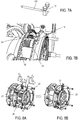
- the figure 5 illustrates the rear ring 22 on its rear support 42.
- the rear support 42 comprises, in this embodiment of the invention three holes 421 for the passage of guides, for translating the rear support 42 and thus the rear ring along said guides.
- the rear support also comprises a plurality of second means for holding and rotating the rear ring relative to its axis along the arrow F1.
- the second means comprise two adjustable rollers 5, a single roller 6, and a groove 7 and a fastening tab 8.
- the operation and the structure of the adjustable and simple rollers has been described with reference to the Figures 3A to 4B .
- the fastening tab 8 and the groove 7 serve to secure the position of the rear crown.
- the fastening tab 8 has a first end 81 which cooperates with the groove 7 and a second end 82 which cooperates with the rear ring so as to hold the latter.
- the groove 7 also serves to release the rotation of the crown back relative to its axis according to the arrow F1. With only the presence of a bracket, but without groove, the rotation of the rear crown would not be free.
- the figure 6 illustrates the front crown 21 on its front support 41.
- the front support 41 comprises, in this embodiment of the invention four holes 421 for the passage of guides, for translating the front support 41 and thus the crown before along said guides.
- the front support also comprises several first means for holding and rotating the front ring relative to its axis along the arrow F2.
- the first means comprise two adjustable rollers 5 and two single rollers 6. The operation and structure of the adjustable and simple rollers has been described with reference to the Figures 3A to 4B .
- the front ring 21 is clamped by four rollers, it is not necessary to secure its attachment to add a groove and a bracket.
- the Figure 7A illustrates an orientation pin 10 having a longitudinal tube 101.
- the tube 101 of the orientation pin is adapted to traverse, as shown in FIG. Figure 7B , screw holes of each of the crowns 21 and rear 22.
- the front and rear crowns have a mark on their periphery, the mark of the front crown to be opposite the mark of the rear crown.
- the figure 8A illustrates how the crown of the epicyclic gear train is mounted by translation and rotation of the front 21 and rear 22 crowns.
Landscapes
- Engineering & Computer Science (AREA)
- General Engineering & Computer Science (AREA)
- Mechanical Engineering (AREA)
- Retarders (AREA)
Description
L'invention se rapporte à un dispositif de montage d'une couronne d'un train épicycloïdal, et plus particulièrement d'un train épicycloïdal à dentures chevrons.The invention relates to a device for mounting a ring gear of an epicyclic gear train, and more particularly to an epicyclic gear train with herringbone gears.
Un train épicycloïdal est un système permettant de transmettre de la puissance sur un arbre mécanique. Dans le cas d'un train épicycloïdal pour turbomachine, la ligne d'entrée provient du moteur de la turbomachine. Le but d'un train épicycloïdal est de réduire la vitesse de rotation du moteur tout en transmettant le couple. Dans ce cas-là, les vitesses et couples sont très élevées, et des réducteurs épicycloïdaux de forte puissance sont nécessaires. Dans une turbomachine, des trains épicycloïdaux sont notamment utilisés en tant que réducteur de vitesse pour réduire la vitesse de rotation du rotor de la soufflante, indépendamment de la vitesse de rotation de la turbine.An epicyclic gear train is a system for transmitting power to a mechanical shaft. In the case of an epicyclic gear train for a turbomachine, the input line comes from the engine of the turbomachine. The purpose of an epicyclic train is to reduce the rotational speed of the engine while transmitting the torque. In this case, the speeds and torques are very high, and high power epicyclic reducers are needed. In a turbomachine, epicyclic gear trains are used in particular as a speed reducer to reduce the speed of rotation of the rotor of the fan, regardless of the speed of rotation of the turbine.
Tel qu'illustré aux
Les satellites de ce type de train comportent des dentures 1121 chevrons, c'est-à-dire une denture qui a un angle par rapport à l'axe de rotation du satellite. Ce type de denture permet d'égaliser les charges axiales. Du fait de la présence de dentures chevron, il est nécessaire pour le montage qu'un des éléments d'engrènement du train soit en deux parties.The satellites of this type of gear comprise
Le réducteur 1 comporte ainsi une couronne composée d'une première demi-couronne, dite couronne avant 21, et d'une deuxième demi-couronne, dite couronne arrière 22. La couronne avant et la couronne arrière comportent des dents 23 sur leur périphérie permettant de les solidariser l'une par rapport à l'autre lorsqu'elles sont en contact et d'ainsi former la couronne du réducteur. Pour ce qui est de l'assemblage de la couronne avant et de la couronne arrière de façon à former la couronne, un centrage fretté est effectué dont le résultat est visible à la
L'invention vise à remédier à tout ou partie des inconvénients de l'état de la technique identifiés ci-dessus, et notamment à proposer des moyens pour permettre de manipuler et maintenir facilement les éléments constituant une couronne d'un réducteur à train épicycloïdal en vue de son montage.The invention aims to remedy all or part of the disadvantages of the state of the art identified above, and in particular to provide means to allow easy handling and maintenance of the elements constituting a ring gear of an epicyclic gear train in view of its assembly.
Dans ce dessein, un aspect de l'invention se rapporte à un dispositif de montage d'une couronne d'un train épicycloïdal, ledit train épicycloïdal s'étendant selon un premier axe, ladite couronne comportant une couronne avant et une couronne arrière, ledit dispositif comportant :
- une pluralité de guides longitudinaux, chaque guide s'étendant selon une direction parallèle au premier axe ;
- un support avant en forme de portion de cercle pour la couronne avant, ledit support avant comportant :
- au moins deux trous pour le passage des guides ;
- une pluralité de premiers moyens de maintien et de rotation par rapport à son axe de la couronne avant, lesdits premiers moyens de maintien et de rotation étant mobiles entre une première position dans laquelle la couronne avant est maintenue et peut tourner par rapport à son axe et une deuxième position dans laquelle la couronne avant n'est pas maintenue ;
- un support arrière en forme de portion de cercle pour la couronne arrière, ledit support arrière comportant :
- au moins deux trous pour le passage des guides ;
- une pluralité de deuxièmes moyens de maintien et de rotation par rapport à son axe de la couronne arrière, lesdits deuxièmes moyens de maintien étant mobiles entre une troisième position dans laquelle la couronne arrière est maintenue et peut tourner par rapport à son axe et une quatrième position dans laquelle la couronne arrière n'est pas maintenue.
- a plurality of longitudinal guides, each guide extending in a direction parallel to the first axis;
- a front support in the form of a portion of a circle for the front crown, said front support comprising:
- at least two holes for the passage of the guides;
- a plurality of first holding and rotation means with respect to its axis of the front ring, said first holding and rotating means being movable between a first position in which the front ring is held and is rotatable relative to its axis and a second position in which the front crown is not maintained;
- a rear support in the form of a portion of a circle for the rear crown, said rear support comprising:
- at least two holes for the passage of the guides;
- a plurality of second means for holding and rotating relative to its axis of the rear ring, said second holding means being movable between a third position in which the rear ring is held and is rotatable relative to its axis and a fourth position in which the rear crown is not maintained.
Ainsi le dispositif de montage selon l'invention permet de faciliter l'assemblage des couronnes avant et arrière et leur montage avec les satellites d'un porte-satellites. En effet, les couronnes peuvent être soutenues grâce aux guides, et aux supports avant et arrière. Elles peuvent translater le long des guides grâce aux trous dans les supports avant et arrière. Et elles sont maintenues grâce aux premiers et deuxièmes moyens de maintien et de rotation qui permettent également aux couronnes de tourner facilement autour de leurs axes respectifs. Ce dispositif de montage permet ainsi de faciliter la manipulation et le montage d'une couronne d'un train épicycloïdal pour un opérateur.Thus, the mounting device according to the invention makes it easier to assemble the front and rear crowns and to assemble them with the satellites of a planet carrier. Indeed, the crowns can be supported thanks to the guides, and to the supports front and back. They can translate along the guides thanks to the holes in the front and rear brackets. And they are maintained by the first and second holding means and rotation which also allow the crowns to rotate easily around their respective axes. This mounting device thus makes it easier to handle and mount a ring gear of an epicyclic gear train for an operator.
Outre les caractéristiques principales qui viennent d'être mentionnées dans le paragraphe précédent, le procédé/dispositif selon l'invention peut présenter une ou plusieurs caractéristiques complémentaires parmi les suivantes, considérées individuellement ou selon les combinaisons techniquement possibles.In addition to the main features which have just been mentioned in the preceding paragraph, the method / device according to the invention may have one or more additional characteristics among the following, considered individually or according to the technically possible combinations.
De façon avantageuse, la pluralité de premiers moyens de maintiens comporte :
- deux galets réglables, lesdits galets réglables comportant une tige de fixation du galet au support avant, ladite tige ayant une longueur réglable et une broche à billes permettant de faire passer lesdits galets réglables de la première position à la deuxième position ; et
- deux galets simples, lesdits galets simples comportant un ressort et une broche à billes permettant de faire passer lesdits galets simples de la première position à la deuxième position, lesdits ressorts étant adaptés pour plaquer le galet contre la couronne avant dans la première position.
- two adjustable rollers, said adjustable rollers comprising a rod for fixing the roller to the front support, said rod having an adjustable length and a ball pin for passing said adjustable rollers from the first position to the second position; and
- two single rollers, said single rollers comprising a spring and a ball pin for passing said single rollers from the first position to the second position, said springs being adapted to press the roller against the front ring in the first position.
De façon avantageuse, la pluralité de deuxièmes moyens de maintiens comporte :
- deux galets réglables, lesdits galets réglables comportant une tige de fixation du galet au support arrière, ladite tige ayant une longueur réglable et une broche à billes permettant de faire passer lesdits galets réglables de la troisième position à la quatrième position ;
- un galet simple, ledit galet simple comportant un ressort et une broche à billes permettant de faire passer ledit galet simple de la troisième position à la deuxième position, ledit ressorts étant adapté pour plaquer le galet contre la couronne arrière dans la troisième position ; et
- une rainure et une patte de fixation, ladite pate de fixation comportant une première extrémité adaptée pour coopérer avec la rainure, ladite première extrémité étant mobile dans la rainure et une deuxième extrémité adaptée pour coopérer avec la couronne arrière de façon à maintenir la couronne arrière.
- two adjustable rollers, said adjustable rollers comprising a rod for fixing the roller to the rear support, said rod having an adjustable length and a ball pin for passing said adjustable rollers from the third position to the fourth position;
- a single roller, said single roller comprising a spring and a ball pin for passing said single roller from the third position to the second position, said springs being adapted to press the roller against the rear ring in the third position; and
- a groove and a fixing lug, said fixing dough having a first end adapted to cooperate with the groove, said first end being movable in the groove and a second end adapted to cooperate with the rear ring so as to maintain the rear ring.
De façon avantageuse, au moins deux guides de la pluralité de guides comportent chacun :
- un manchon comportant une première extrémité et une deuxième extrémité ;
- une première portion de guide, une troisième extrémité de la première portion étant adaptée pour s'insérer dans la première extrémité du manchon ;
- une deuxième portion de guide, une quatrième extrémité de la deuxième portion étant adaptée pour s'insérer dans la deuxième extrémité du manchon ;
- a sleeve having a first end and a second end;
- a first guide portion, a third end of the first portion being adapted to fit into the first end of the sleeve;
- a second guide portion, a fourth end of the second portion being adapted to be inserted into the second end of the sleeve;
De façon avantageuse, le dispositif comporte une broche d'orientation, ladite broche comportant un tube longitudinal adaptée pour s'insérer à la fois au travers d'un premier trou de la couronne avant et d'un deuxième trou de la couronne arrière.Advantageously, the device comprises an orientation pin, said pin comprising a longitudinal tube adapted to fit both through a first hole of the front ring and a second hole of the rear ring.
D'autres caractéristiques et avantages de l'invention ressortiront à la lecture de la description qui suit, en référence aux figures annexées, qui illustrent :
- la
figures 1A une vue schématique d'un train épicycloïdal ; - la
figure 1B , une vue de face du train de lafigure 1 ; - la
figure 1C , une vue en coupe d'une couronne avant et d'une couronne arrière du train de lafigure 1 ; - la
figure 2 , une vue schématique d'un berceau de montage d'un train épicycloïdal et d'un dispositif de montage d'une couronne d'un train selon un mode de réalisation de l'invention ; - les
figures 3A, 3B, 4A et 4B , des vues schématiques de moyens de maintien et de rotation d'un dispositif de montage d'une couronne d'un train selon un mode de réalisation de l'invention ; - la
figure 5 , une vue schématique d'une couronne arrière et d'un support arrière d'un dispositif de montage d'une couronne d'un train selon un mode de réalisation de l'invention ; - la
figure 6 , une vue schématique d'une couronne avant et d'un support avant d'un dispositif de montage d'une couronne d'un train selon un mode de réalisation de l'invention ; - la
figure 7A , une vue schématique d'une broche d'orientation d'un dispositif de montage d'une couronne d'un train selon un mode de réalisation de l'invention ; - la
figure 7B , une vue schématique d'une couronne avant, d'une couronne arrière et de la broche d'orientation de lafigure 7A ; - les
figures 8A et 8B , des vues schématiques d'un dispositif de montage d'une couronne d'un train selon un mode de réalisation de l'invention dans différentes positions.
- the
Figures 1A a schematic view of an epicyclic gear train; - the
Figure 1B , a front view of the train of thefigure 1 ; - the
figure 1C , a sectional view of a front crown and a rear crown of the train of thefigure 1 ; - the
figure 2 , a schematic view of a mounting cradle of an epicyclic gear train and a device for mounting a crown of a train according to one embodiment of the invention; - the
FIGS. 3A, 3B, 4A and 4B schematic views of means for holding and rotating a device for mounting a crown of a train according to one embodiment of the invention; - the
figure 5 , a schematic view of a rear crown and a rear support of a device for mounting a crown of a train according to one embodiment of the invention; - the
figure 6 , a schematic view of a front crown and a front support of a device for mounting a crown of a train according to one embodiment of the invention; - the
Figure 7A , a schematic view of an orientation pin of a device for mounting a crown of a train according to one embodiment of the invention; - the
Figure 7B , a schematic view of a front crown, a rear crown and the orientation pin of theFigure 7A ; - the
Figures 8A and 8B , schematic views of a device for mounting a ring of a train according to one embodiment of the invention in different positions.
Pour plus de clarté, les éléments identiques ou similaires sont repérés par des signes de référence identiques sur l'ensemble des figures.For the sake of clarity, identical or similar elements are marked with identical reference signs throughout the figures.
La
Sur la
Le berceau de montage 3 du train épicycloïdal coopère avec le dispositif de montage d'une couronne du train épicycloïdal pour effectuer l'assemblage des différents éléments constituant le train épicycloïdal. Il est ainsi visible sur la
Le dispositif de montage de la couronne du train épicycloïdal comporte un support avant 41. Le support avant 41 comporte quatre trous 411 (dont un non visible) qui permettent aux guides 34 de les traverser. Ainsi, le support avant 41 peut translater le long des guides 34. Le support avant 41 a une forme en portion de cercle mais n'est pas complètement circulaire de préférence. En effet, l'espace laissé permet à un opérateur d'accéder plus facilement aux éléments, notamment à la couronne avant, que si le support avant 41 était complètement circulaire. Le support avant 41 comporte quatre premiers moyens 412 de maintien et de rotation de la couronne avant par rapport à son axe qui est confondu avec le premier axe X1. Les premiers moyens 412 de maintien et de rotation comportent dans cet exemple de réalisation des galets qui seront décrits plus en détail en référence aux figures suivantes.The device for mounting the crown of the planetary gear train comprises a
Le dispositif de montage de la couronne du train épicycloïdal comporte un support arrière 42. Le support arrière 42 comporte trois trous 421 qui permettent aux guides 34 de traverser. Ainsi, le support arrière 42 peut translater également le long des guides 34. Le support arrière 42 a une forme en portion de cercle mais n'est pas complètement circulaire de préférence. En effet, l'espace laissé permet à un opérateur d'accéder plus facilement aux éléments, notamment à la couronne arrière, que si le support arrière 42 était complètement circulaire. Le support arrière 42 comporte quatre deuxième moyens 422 de maintien et de rotation de la couronne arrière par rapport à son axe qui est confondu avec le premier axe X1. Les deuxièmes moyens 422 de maintien et de rotation comportent dans cet exemple de réalisation des galets et une rainure et une patte de fixation qui seront décrits plus en détail en référence aux figures suivantes.The mounting device of the epicyclic gear ring comprises a
Les supports avant et arrière ont pour fonction de rigidifier le dispositif entre les guides et de faciliter la translation des couronnes le long des guides en s'assurant que les galets se déplacent et qu'un galet ne reste pas à une position différente de celle des autres galets.The front and rear supports have the function of stiffening the device between the guides and facilitate the translation of the rings along the guides by ensuring that the rollers move and that a roller does not remain at a position different from that of the other pebbles.
Les supports avant et arrière, et donc les couronnes avant et arrière sont supportés par les guides présents sur le berceau de montage. Plusieurs guides du dispositif comportent une première portion de guide 341, une deuxième portion de guide 342 et un manchon. Une troisième extrémité de la première portion de guide peut s'insérer dans une première extrémité du manchon, et une quatrième extrémité de la deuxième portion de guide peut s'insérer dans une deuxième extrémité du manchon. Il est visible sur la
La
La
Dans la deuxième/quatrième position illustrée à la
Dans la première/troisième position illustrée à la
La
La
La
La
Il convient de faire translater les couronnes avant 21 et arrière 22 l'une vers l'autre et vers les dentures des satellites du porte-satellites selon les flèches F3 et F4. La couronne avant 21 translate le long des guides 34 selon la flèche F3 et la couronne arrière 22 translate le long des guides 34 selon la flèche F4. Il faut s'assurer, qu'une fois qu'on arrive au quasi contact entre les dentures des couronnes avant et arrière, les trous des vis tombent les uns en face des autres, et notamment ceux permettant l'orientation. La broche d'orientation présentée aux
L'invention n'est pas limitée aux modes de réalisation précédemment décrits en référence aux figures et des variantes pourraient être envisagées sans sortir du cadre de l'invention.The invention is not limited to the embodiments previously described with reference to the figures and variants could be envisaged without departing from the scope of the invention.
Claims (5)
- Device for installing a ring of a planetary gear train (1), the said planetary gear train extending in a first axis (X1), the said ring including a front ring (21) and a rear ring (22), the said device containing:- a plurality of longitudinal guides (34), each guide extending in a direction parallel to the first axis;characterised in that the device comprises:- a front bracket (41) having the shape of an arc of a circle for the front ring, the said front bracket containing:- at least two holes (34) allowing the guides to pass through;- a plurality of first means (412) of holding the front ring and of rotating with respect to its axis, where the said first holding and rotation means can move between a first position in which the front ring is held, and can rotate around its axis, and a second position in which the front ring is not held in place;- a rear bracket (42) having the shape of an arc of a circle for the rear ring, the said rear bracket containing:- at least two holes (421) allowing the guides to pass through;- a plurality of second means (422) of holding the rear ring and of rotating with respect to its axis, where the said second holding means can move between a third position in which the rear ring is held, and can rotate around its axis, and a fourth position in which the rear ring is not held in place.
- Device according to the previous claim characterised by the fact that the plurality of first holding means contain:- two adjustable rollers (5), where the said adjustable rollers contain a pin (51) to attach the roller to the front bracket, where the length (L) of the said pin is adjustable and where a ball lock pin (52) enables the said adjustable rollers to be moved from the first position to the second position; and- two simple rollers (6), where the said simple rollers contain a spring (62) and a ball lock pin (61) enabling the said simple rollers to move from the first position to the second position, where the said springs are designed to press the roller against the front ring in the first position.
- Device according to any of the previous claims, characterised in that the plurality of second holding means include:- two adjustable rollers, where the said adjustable rollers contain a pin to attach the roller to the rear bracket, where the length of the said pin is adjustable and where a ball lock pin enables the said adjustable rollers to be moved from the third position to the fourth position;- a simple roller, where the said simple roller has a spring and a ball lock pin enabling the said simple roller to be moved from the third position to the second position, and where the said spring is designed to press the roller against the rear ring in the third position; and- a groove (7) and a retaining bracket (8), where the said retaining bracket contains a first end designed to work in tandem with the groove, where the said first end can move in the groove, and a second end designed to work in tandem with the rear ring to hold the rear ring in place.
- Device according to any of the previous claims, characterised by the fact that at least two of the plurality of guides each includes:- a sleeve tube (343) including a first end and a second end;- a first guide portion (341), where a third end of the first portion is designed to be inserted in the first end of the sleeve tube;- a second guide portion (342), where a fourth end of the second portion is designed to be inserted in the second end of the sleeve tube;each sleeve tube being connected to the other sleeve tube by means of a support element, the said support element containing a stand designed to rest on a surface.
- Device according to any of the previous claims, characterised by the fact that it contains a guide pin (10), the said pin containing a longitudinal tube (101) designed to be inserted simultaneously through a first hole of the front ring and a second hole of the rear ring.
Applications Claiming Priority (2)
| Application Number | Priority Date | Filing Date | Title |
|---|---|---|---|
| FR1559272A FR3041730B1 (en) | 2015-09-30 | 2015-09-30 | DEVICE FOR MOUNTING A CROWN OF AN EPICYCLOIDAL TRAIN |
| PCT/FR2016/052404 WO2017055713A1 (en) | 2015-09-30 | 2016-09-22 | Device for mounting a ring gear of an epicyclic gear train |
Publications (2)
| Publication Number | Publication Date |
|---|---|
| EP3356702A1 EP3356702A1 (en) | 2018-08-08 |
| EP3356702B1 true EP3356702B1 (en) | 2019-11-06 |
Family
ID=55025184
Family Applications (1)
| Application Number | Title | Priority Date | Filing Date |
|---|---|---|---|
| EP16785207.8A Active EP3356702B1 (en) | 2015-09-30 | 2016-09-22 | Device for mounting a ring gear of an epicyclic gear train |
Country Status (5)
| Country | Link |
|---|---|
| US (1) | US10974376B2 (en) |
| EP (1) | EP3356702B1 (en) |
| CN (1) | CN108138940B (en) |
| FR (1) | FR3041730B1 (en) |
| WO (1) | WO2017055713A1 (en) |
Families Citing this family (8)
| Publication number | Priority date | Publication date | Assignee | Title |
|---|---|---|---|---|
| FR3042568B1 (en) * | 2015-10-16 | 2017-11-10 | Hispano-Suiza | TOOTHED CROWN FOR EPICYCLOIDAL REDUCER |
| FR3068750B1 (en) | 2017-07-05 | 2020-02-07 | Safran Transmission Systems | EPICYCLOIDAL OR PLANETARY REDUCER CROWN FOR A TURBOMACHINE |
| FR3090061B1 (en) * | 2018-12-13 | 2021-01-29 | Safran Trans Systems | SATELLITE CARRIER FOR A SPEED REDUCER |
| DE102019006200A1 (en) * | 2019-03-30 | 2020-10-01 | Aerospace Transmission Technologies GmbH | Housing for a transmission and method for assembling a transmission designed as a planetary transmission |
| JP7582927B2 (en) * | 2021-11-18 | 2024-11-13 | 本田技研工業株式会社 | Wheel Retention Device |
| CN115041961A (en) * | 2022-06-29 | 2022-09-13 | 方盛车桥(柳州)有限公司 | Full-automatic multi-shaft gear splicing table |
| EP4325091A1 (en) * | 2022-08-18 | 2024-02-21 | Nordex Energy SE & Co. KG | Assembly for a gearbox for a wind turbine, arrangement, kit, gearbox for a wind turbine, method for transporting an assembly for a gearbox and method for assembling a wind turbine |
| TWI849813B (en) * | 2023-03-22 | 2024-07-21 | 鐵禾瑪精密有限公司 | Height-adjustable bicycle maintenance stand |
Family Cites Families (16)
| Publication number | Priority date | Publication date | Assignee | Title |
|---|---|---|---|---|
| US4202539A (en) * | 1978-11-15 | 1980-05-13 | Avco Corporation | Engine work stand |
| US4716271A (en) * | 1984-09-28 | 1987-12-29 | Welding Services, Inc. | Apparatus for positioning a tool with respect to a cylindrical work piece |
| US5282403A (en) * | 1992-07-30 | 1994-02-01 | Rouleau Georges O | Guide apparatus for an elongated workpiece |
| US5421623A (en) * | 1994-05-26 | 1995-06-06 | Cassin; Allen E. | Friction sealed coupling for pipe |
| JP3331485B2 (en) * | 1994-09-29 | 2002-10-07 | 株式会社ジオトップ | Construction method of foundation pile and ring holder device for foundation pile construction |
| US6386789B1 (en) * | 1999-09-24 | 2002-05-14 | Paul D. Chausse | Quick release ball type locking pin and production tool |
| US6168427B1 (en) * | 1999-10-05 | 2001-01-02 | Taiwan Semiconductor Manufacturing Co., Ltd | Apparatus for guiding the removal of a processing tube from a semiconductor furnace |
| US6901823B2 (en) * | 2003-10-17 | 2005-06-07 | Carl J. Ernesti | Reversible magnetic ratcheting spud wrench |
| TWI242639B (en) * | 2003-10-21 | 2005-11-01 | Ind Tech Res Inst | Humidity sensor element, device and method for manufacturing thereof |
| US8667688B2 (en) * | 2006-07-05 | 2014-03-11 | United Technologies Corporation | Method of assembly for gas turbine fan drive gear system |
| KR100765087B1 (en) * | 2006-12-01 | 2007-10-09 | 현대모비스 주식회사 | Vehicle steering angle sensor assembly |
| US8241160B2 (en) * | 2010-07-28 | 2012-08-14 | Mbi Co., Ltd | Transmission for use in a motor and a pedal-powered vehicle and transmission method thereof |
| JP5606471B2 (en) * | 2012-02-20 | 2014-10-15 | 株式会社東芝 | Substrate rotation holding device and substrate processing apparatus |
| EP2834503B1 (en) * | 2012-02-23 | 2018-04-11 | Safran Aircraft Engines | Device for recovering lubricating oil from an epicyclic reduction gear |
| CN104373517B (en) * | 2014-10-22 | 2016-08-31 | 北京航空航天大学 | A kind of box-like equal support method of eccentric shaft-connection rod set and reductor thereof |
| CN204115684U (en) * | 2014-10-24 | 2015-01-21 | 中国石油天然气集团公司 | A kind of elbow residual wall thickness pick-up unit |
-
2015
- 2015-09-30 FR FR1559272A patent/FR3041730B1/en active Active
-
2016
- 2016-09-22 CN CN201680056423.2A patent/CN108138940B/en active Active
- 2016-09-22 EP EP16785207.8A patent/EP3356702B1/en active Active
- 2016-09-22 WO PCT/FR2016/052404 patent/WO2017055713A1/en active Application Filing
- 2016-09-22 US US15/762,201 patent/US10974376B2/en active Active
Non-Patent Citations (1)
| Title |
|---|
| None * |
Also Published As
| Publication number | Publication date |
|---|---|
| EP3356702A1 (en) | 2018-08-08 |
| US20180290278A1 (en) | 2018-10-11 |
| CN108138940A (en) | 2018-06-08 |
| CN108138940B (en) | 2020-12-04 |
| FR3041730B1 (en) | 2018-12-07 |
| WO2017055713A1 (en) | 2017-04-06 |
| FR3041730A1 (en) | 2017-03-31 |
| US10974376B2 (en) | 2021-04-13 |
Similar Documents
| Publication | Publication Date | Title |
|---|---|---|
| EP3356702B1 (en) | Device for mounting a ring gear of an epicyclic gear train | |
| CA2751521C (en) | Lubrication and cooling of a reduction gear with epicyclic gear train | |
| FR3127269A1 (en) | AIRCRAFT TURBOMACHINE WITH OFF-AXIS PROPELLER | |
| EP3137740B1 (en) | Assembly for aircraft turbine engine and method for mounting same | |
| EP2734741B1 (en) | Anti-rotation device for a large-size nut | |
| EP3137741B1 (en) | Aircraft turbine engine with improved drawing of mechanical power | |
| EP3956555B1 (en) | Reduction gearbox of a turbomachine | |
| EP3649373B1 (en) | Ring gear for an epicyclic or planetary reduction gear of a turbomachine | |
| EP3740657B1 (en) | Oil collector for speed reducer, in particular of a turbomachine, and associated speed reducer and turbomachine | |
| EP3994341B1 (en) | Device for damping a rolling bearing, comprising a rigid support passing through a flexible cage | |
| FR2995053A1 (en) | TURBOMACHINE MOVEMENT GEAR BOX COMPRISING A GEAR-LINKED CINEMA CHAIN EXTENDING IN NON-PARALLEL PLANS | |
| EP3601747B1 (en) | Accessory gearbox for a gas turbine engine | |
| CA2981171C (en) | Turboshaft engine mountable in a reduction gearbox | |
| FR3025780A1 (en) | ROLLING TRAIN | |
| EP3416886B1 (en) | Reduction gear with input/output rotation reversal | |
| FR3064326A1 (en) | ROLLER GEAR ELEMENT | |
| FR3014141A1 (en) | FIXED TURBOMACHINE RECEIVER PART COMPRISING WITHIN A FIXED FIXTURE AN ASSEMBLY INCLUDING SERVITUDES | |
| EP3803159B1 (en) | Method for assembling a reduction gear and facility for implementing the method | |
| EP3721118B1 (en) | Planetary gear train | |
| FR3042012A1 (en) | DEVICE FOR MOUNTING AN EPICYCLOIDAL TRAIN | |
| EP4339099A1 (en) | Speed reducer for a device for driving a wheel of an aircraft landing gear | |
| EP4339097A1 (en) | Device for driving at least one wheel of an aircraft landing gear | |
| FR3125319A1 (en) | MECHANICAL ASSEMBLY AND MECHANICAL REDUCER OF AIRCRAFT TURBOMACHINE COMPRISING SUCH AN ASSEMBLY | |
| FR2878300A1 (en) | DEVICE AND METHOD FOR ASSEMBLING TWO COAXIAL TREES WITH INDEPENDENT ROTATION |
Legal Events
| Date | Code | Title | Description |
|---|---|---|---|
| STAA | Information on the status of an ep patent application or granted ep patent |
Free format text: STATUS: UNKNOWN |
|
| STAA | Information on the status of an ep patent application or granted ep patent |
Free format text: STATUS: THE INTERNATIONAL PUBLICATION HAS BEEN MADE |
|
| PUAI | Public reference made under article 153(3) epc to a published international application that has entered the european phase |
Free format text: ORIGINAL CODE: 0009012 |
|
| STAA | Information on the status of an ep patent application or granted ep patent |
Free format text: STATUS: REQUEST FOR EXAMINATION WAS MADE |
|
| 17P | Request for examination filed |
Effective date: 20180320 |
|
| AK | Designated contracting states |
Kind code of ref document: A1 Designated state(s): AL AT BE BG CH CY CZ DE DK EE ES FI FR GB GR HR HU IE IS IT LI LT LU LV MC MK MT NL NO PL PT RO RS SE SI SK SM TR |
|
| AX | Request for extension of the european patent |
Extension state: BA ME |
|
| DAV | Request for validation of the european patent (deleted) | ||
| DAX | Request for extension of the european patent (deleted) | ||
| GRAP | Despatch of communication of intention to grant a patent |
Free format text: ORIGINAL CODE: EPIDOSNIGR1 |
|
| STAA | Information on the status of an ep patent application or granted ep patent |
Free format text: STATUS: GRANT OF PATENT IS INTENDED |
|
| INTG | Intention to grant announced |
Effective date: 20190712 |
|
| GRAS | Grant fee paid |
Free format text: ORIGINAL CODE: EPIDOSNIGR3 |
|
| GRAA | (expected) grant |
Free format text: ORIGINAL CODE: 0009210 |
|
| STAA | Information on the status of an ep patent application or granted ep patent |
Free format text: STATUS: THE PATENT HAS BEEN GRANTED |
|
| AK | Designated contracting states |
Kind code of ref document: B1 Designated state(s): AL AT BE BG CH CY CZ DE DK EE ES FI FR GB GR HR HU IE IS IT LI LT LU LV MC MK MT NL NO PL PT RO RS SE SI SK SM TR |
|
| REG | Reference to a national code |
Ref country code: GB Ref legal event code: FG4D Free format text: NOT ENGLISH |
|
| REG | Reference to a national code |
Ref country code: CH Ref legal event code: EP Ref country code: AT Ref legal event code: REF Ref document number: 1199154 Country of ref document: AT Kind code of ref document: T Effective date: 20191115 |
|
| REG | Reference to a national code |
Ref country code: IE Ref legal event code: FG4D Free format text: LANGUAGE OF EP DOCUMENT: FRENCH |
|
| REG | Reference to a national code |
Ref country code: DE Ref legal event code: R096 Ref document number: 602016023943 Country of ref document: DE |
|
| REG | Reference to a national code |
Ref country code: NL Ref legal event code: MP Effective date: 20191106 |
|
| REG | Reference to a national code |
Ref country code: LT Ref legal event code: MG4D |
|
| PG25 | Lapsed in a contracting state [announced via postgrant information from national office to epo] |
Ref country code: NL Free format text: LAPSE BECAUSE OF FAILURE TO SUBMIT A TRANSLATION OF THE DESCRIPTION OR TO PAY THE FEE WITHIN THE PRESCRIBED TIME-LIMIT Effective date: 20191106 Ref country code: NO Free format text: LAPSE BECAUSE OF FAILURE TO SUBMIT A TRANSLATION OF THE DESCRIPTION OR TO PAY THE FEE WITHIN THE PRESCRIBED TIME-LIMIT Effective date: 20200206 Ref country code: PL Free format text: LAPSE BECAUSE OF FAILURE TO SUBMIT A TRANSLATION OF THE DESCRIPTION OR TO PAY THE FEE WITHIN THE PRESCRIBED TIME-LIMIT Effective date: 20191106 Ref country code: GR Free format text: LAPSE BECAUSE OF FAILURE TO SUBMIT A TRANSLATION OF THE DESCRIPTION OR TO PAY THE FEE WITHIN THE PRESCRIBED TIME-LIMIT Effective date: 20200207 Ref country code: BG Free format text: LAPSE BECAUSE OF FAILURE TO SUBMIT A TRANSLATION OF THE DESCRIPTION OR TO PAY THE FEE WITHIN THE PRESCRIBED TIME-LIMIT Effective date: 20200206 Ref country code: FI Free format text: LAPSE BECAUSE OF FAILURE TO SUBMIT A TRANSLATION OF THE DESCRIPTION OR TO PAY THE FEE WITHIN THE PRESCRIBED TIME-LIMIT Effective date: 20191106 Ref country code: LT Free format text: LAPSE BECAUSE OF FAILURE TO SUBMIT A TRANSLATION OF THE DESCRIPTION OR TO PAY THE FEE WITHIN THE PRESCRIBED TIME-LIMIT Effective date: 20191106 Ref country code: SE Free format text: LAPSE BECAUSE OF FAILURE TO SUBMIT A TRANSLATION OF THE DESCRIPTION OR TO PAY THE FEE WITHIN THE PRESCRIBED TIME-LIMIT Effective date: 20191106 Ref country code: LV Free format text: LAPSE BECAUSE OF FAILURE TO SUBMIT A TRANSLATION OF THE DESCRIPTION OR TO PAY THE FEE WITHIN THE PRESCRIBED TIME-LIMIT Effective date: 20191106 Ref country code: PT Free format text: LAPSE BECAUSE OF FAILURE TO SUBMIT A TRANSLATION OF THE DESCRIPTION OR TO PAY THE FEE WITHIN THE PRESCRIBED TIME-LIMIT Effective date: 20200306 |
|
| PG25 | Lapsed in a contracting state [announced via postgrant information from national office to epo] |
Ref country code: RS Free format text: LAPSE BECAUSE OF FAILURE TO SUBMIT A TRANSLATION OF THE DESCRIPTION OR TO PAY THE FEE WITHIN THE PRESCRIBED TIME-LIMIT Effective date: 20191106 Ref country code: HR Free format text: LAPSE BECAUSE OF FAILURE TO SUBMIT A TRANSLATION OF THE DESCRIPTION OR TO PAY THE FEE WITHIN THE PRESCRIBED TIME-LIMIT Effective date: 20191106 Ref country code: IS Free format text: LAPSE BECAUSE OF FAILURE TO SUBMIT A TRANSLATION OF THE DESCRIPTION OR TO PAY THE FEE WITHIN THE PRESCRIBED TIME-LIMIT Effective date: 20200306 |
|
| PG25 | Lapsed in a contracting state [announced via postgrant information from national office to epo] |
Ref country code: AL Free format text: LAPSE BECAUSE OF FAILURE TO SUBMIT A TRANSLATION OF THE DESCRIPTION OR TO PAY THE FEE WITHIN THE PRESCRIBED TIME-LIMIT Effective date: 20191106 |
|
| PG25 | Lapsed in a contracting state [announced via postgrant information from national office to epo] |
Ref country code: RO Free format text: LAPSE BECAUSE OF FAILURE TO SUBMIT A TRANSLATION OF THE DESCRIPTION OR TO PAY THE FEE WITHIN THE PRESCRIBED TIME-LIMIT Effective date: 20191106 Ref country code: ES Free format text: LAPSE BECAUSE OF FAILURE TO SUBMIT A TRANSLATION OF THE DESCRIPTION OR TO PAY THE FEE WITHIN THE PRESCRIBED TIME-LIMIT Effective date: 20191106 Ref country code: CZ Free format text: LAPSE BECAUSE OF FAILURE TO SUBMIT A TRANSLATION OF THE DESCRIPTION OR TO PAY THE FEE WITHIN THE PRESCRIBED TIME-LIMIT Effective date: 20191106 Ref country code: DK Free format text: LAPSE BECAUSE OF FAILURE TO SUBMIT A TRANSLATION OF THE DESCRIPTION OR TO PAY THE FEE WITHIN THE PRESCRIBED TIME-LIMIT Effective date: 20191106 Ref country code: EE Free format text: LAPSE BECAUSE OF FAILURE TO SUBMIT A TRANSLATION OF THE DESCRIPTION OR TO PAY THE FEE WITHIN THE PRESCRIBED TIME-LIMIT Effective date: 20191106 |
|
| REG | Reference to a national code |
Ref country code: DE Ref legal event code: R097 Ref document number: 602016023943 Country of ref document: DE |
|
| REG | Reference to a national code |
Ref country code: AT Ref legal event code: MK05 Ref document number: 1199154 Country of ref document: AT Kind code of ref document: T Effective date: 20191106 |
|
| PG25 | Lapsed in a contracting state [announced via postgrant information from national office to epo] |
Ref country code: SK Free format text: LAPSE BECAUSE OF FAILURE TO SUBMIT A TRANSLATION OF THE DESCRIPTION OR TO PAY THE FEE WITHIN THE PRESCRIBED TIME-LIMIT Effective date: 20191106 Ref country code: SM Free format text: LAPSE BECAUSE OF FAILURE TO SUBMIT A TRANSLATION OF THE DESCRIPTION OR TO PAY THE FEE WITHIN THE PRESCRIBED TIME-LIMIT Effective date: 20191106 |
|
| PLBE | No opposition filed within time limit |
Free format text: ORIGINAL CODE: 0009261 |
|
| STAA | Information on the status of an ep patent application or granted ep patent |
Free format text: STATUS: NO OPPOSITION FILED WITHIN TIME LIMIT |
|
| 26N | No opposition filed |
Effective date: 20200807 |
|
| PG25 | Lapsed in a contracting state [announced via postgrant information from national office to epo] |
Ref country code: SI Free format text: LAPSE BECAUSE OF FAILURE TO SUBMIT A TRANSLATION OF THE DESCRIPTION OR TO PAY THE FEE WITHIN THE PRESCRIBED TIME-LIMIT Effective date: 20191106 Ref country code: AT Free format text: LAPSE BECAUSE OF FAILURE TO SUBMIT A TRANSLATION OF THE DESCRIPTION OR TO PAY THE FEE WITHIN THE PRESCRIBED TIME-LIMIT Effective date: 20191106 |
|
| PGFP | Annual fee paid to national office [announced via postgrant information from national office to epo] |
Ref country code: IT Payment date: 20200824 Year of fee payment: 5 |
|
| REG | Reference to a national code |
Ref country code: CH Ref legal event code: PL |
|
| REG | Reference to a national code |
Ref country code: BE Ref legal event code: MM Effective date: 20200930 |
|
| PG25 | Lapsed in a contracting state [announced via postgrant information from national office to epo] |
Ref country code: LU Free format text: LAPSE BECAUSE OF NON-PAYMENT OF DUE FEES Effective date: 20200922 |
|
| PG25 | Lapsed in a contracting state [announced via postgrant information from national office to epo] |
Ref country code: BE Free format text: LAPSE BECAUSE OF NON-PAYMENT OF DUE FEES Effective date: 20200930 Ref country code: CH Free format text: LAPSE BECAUSE OF NON-PAYMENT OF DUE FEES Effective date: 20200930 Ref country code: LI Free format text: LAPSE BECAUSE OF NON-PAYMENT OF DUE FEES Effective date: 20200930 Ref country code: IE Free format text: LAPSE BECAUSE OF NON-PAYMENT OF DUE FEES Effective date: 20200922 |
|
| PG25 | Lapsed in a contracting state [announced via postgrant information from national office to epo] |
Ref country code: TR Free format text: LAPSE BECAUSE OF FAILURE TO SUBMIT A TRANSLATION OF THE DESCRIPTION OR TO PAY THE FEE WITHIN THE PRESCRIBED TIME-LIMIT Effective date: 20191106 Ref country code: MT Free format text: LAPSE BECAUSE OF FAILURE TO SUBMIT A TRANSLATION OF THE DESCRIPTION OR TO PAY THE FEE WITHIN THE PRESCRIBED TIME-LIMIT Effective date: 20191106 Ref country code: CY Free format text: LAPSE BECAUSE OF FAILURE TO SUBMIT A TRANSLATION OF THE DESCRIPTION OR TO PAY THE FEE WITHIN THE PRESCRIBED TIME-LIMIT Effective date: 20191106 |
|
| PG25 | Lapsed in a contracting state [announced via postgrant information from national office to epo] |
Ref country code: MK Free format text: LAPSE BECAUSE OF FAILURE TO SUBMIT A TRANSLATION OF THE DESCRIPTION OR TO PAY THE FEE WITHIN THE PRESCRIBED TIME-LIMIT Effective date: 20191106 Ref country code: MC Free format text: LAPSE BECAUSE OF FAILURE TO SUBMIT A TRANSLATION OF THE DESCRIPTION OR TO PAY THE FEE WITHIN THE PRESCRIBED TIME-LIMIT Effective date: 20191106 |
|
| PG25 | Lapsed in a contracting state [announced via postgrant information from national office to epo] |
Ref country code: IT Free format text: LAPSE BECAUSE OF NON-PAYMENT OF DUE FEES Effective date: 20210922 |
|
| PGFP | Annual fee paid to national office [announced via postgrant information from national office to epo] |
Ref country code: DE Payment date: 20240820 Year of fee payment: 9 |
|
| PGFP | Annual fee paid to national office [announced via postgrant information from national office to epo] |
Ref country code: GB Payment date: 20240820 Year of fee payment: 9 |
|
| PGFP | Annual fee paid to national office [announced via postgrant information from national office to epo] |
Ref country code: FR Payment date: 20240820 Year of fee payment: 9 |