EP3339891A1 - Method and apparatus for estimating position in wireless communication system - Google Patents
Method and apparatus for estimating position in wireless communication system Download PDFInfo
- Publication number
- EP3339891A1 EP3339891A1 EP16839636.4A EP16839636A EP3339891A1 EP 3339891 A1 EP3339891 A1 EP 3339891A1 EP 16839636 A EP16839636 A EP 16839636A EP 3339891 A1 EP3339891 A1 EP 3339891A1
- Authority
- EP
- European Patent Office
- Prior art keywords
- transmitter
- magnetic field
- field signal
- receiver
- terminal
- Prior art date
- Legal status (The legal status is an assumption and is not a legal conclusion. Google has not performed a legal analysis and makes no representation as to the accuracy of the status listed.)
- Ceased
Links
Images


Classifications
-
- H—ELECTRICITY
- H04—ELECTRIC COMMUNICATION TECHNIQUE
- H04W—WIRELESS COMMUNICATION NETWORKS
- H04W64/00—Locating users or terminals or network equipment for network management purposes, e.g. mobility management
- H04W64/003—Locating users or terminals or network equipment for network management purposes, e.g. mobility management locating network equipment
-
- H—ELECTRICITY
- H04—ELECTRIC COMMUNICATION TECHNIQUE
- H04W—WIRELESS COMMUNICATION NETWORKS
- H04W4/00—Services specially adapted for wireless communication networks; Facilities therefor
- H04W4/02—Services making use of location information
-
- G—PHYSICS
- G01—MEASURING; TESTING
- G01B—MEASURING LENGTH, THICKNESS OR SIMILAR LINEAR DIMENSIONS; MEASURING ANGLES; MEASURING AREAS; MEASURING IRREGULARITIES OF SURFACES OR CONTOURS
- G01B7/00—Measuring arrangements characterised by the use of electric or magnetic techniques
- G01B7/14—Measuring arrangements characterised by the use of electric or magnetic techniques for measuring distance or clearance between spaced objects or spaced apertures
-
- G—PHYSICS
- G01—MEASURING; TESTING
- G01C—MEASURING DISTANCES, LEVELS OR BEARINGS; SURVEYING; NAVIGATION; GYROSCOPIC INSTRUMENTS; PHOTOGRAMMETRY OR VIDEOGRAMMETRY
- G01C21/00—Navigation; Navigational instruments not provided for in groups G01C1/00 - G01C19/00
- G01C21/20—Instruments for performing navigational calculations
- G01C21/206—Instruments for performing navigational calculations specially adapted for indoor navigation
-
- G—PHYSICS
- G01—MEASURING; TESTING
- G01R—MEASURING ELECTRIC VARIABLES; MEASURING MAGNETIC VARIABLES
- G01R33/00—Arrangements or instruments for measuring magnetic variables
- G01R33/20—Arrangements or instruments for measuring magnetic variables involving magnetic resonance
- G01R33/44—Arrangements or instruments for measuring magnetic variables involving magnetic resonance using nuclear magnetic resonance [NMR]
- G01R33/48—NMR imaging systems
- G01R33/483—NMR imaging systems with selection of signals or spectra from particular regions of the volume, e.g. in vivo spectroscopy
- G01R33/4833—NMR imaging systems with selection of signals or spectra from particular regions of the volume, e.g. in vivo spectroscopy using spatially selective excitation of the volume of interest, e.g. selecting non-orthogonal or inclined slices
-
- G—PHYSICS
- G01—MEASURING; TESTING
- G01S—RADIO DIRECTION-FINDING; RADIO NAVIGATION; DETERMINING DISTANCE OR VELOCITY BY USE OF RADIO WAVES; LOCATING OR PRESENCE-DETECTING BY USE OF THE REFLECTION OR RERADIATION OF RADIO WAVES; ANALOGOUS ARRANGEMENTS USING OTHER WAVES
- G01S11/00—Systems for determining distance or velocity not using reflection or reradiation
- G01S11/12—Systems for determining distance or velocity not using reflection or reradiation using electromagnetic waves other than radio waves
-
- H—ELECTRICITY
- H04—ELECTRIC COMMUNICATION TECHNIQUE
- H04W—WIRELESS COMMUNICATION NETWORKS
- H04W4/00—Services specially adapted for wireless communication networks; Facilities therefor
- H04W4/02—Services making use of location information
- H04W4/029—Location-based management or tracking services
-
- H—ELECTRICITY
- H04—ELECTRIC COMMUNICATION TECHNIQUE
- H04W—WIRELESS COMMUNICATION NETWORKS
- H04W64/00—Locating users or terminals or network equipment for network management purposes, e.g. mobility management
Definitions
- the present disclosure generally relates to a method and apparatus for estimating a position in a communication system, and more particularly, to a method and apparatus for estimating a position of a terminal based on a magnetic field signal.
- the 5G communication system or the pre-5G communication system is called a beyond 4G network communication system after 4G network or a post LTE system after an LTE system.
- 5G communication systems are being considered for implementation in ultra-high frequency (mmWave) bands (for example, 60 GHz bands).
- mmWave ultra-high frequency
- FD-MIMO Full Dimensional MIMO
- array antenna analog beamforming, and large scale antenna technologies are being discussed.
- technologies such as an evolved small cell, an advanced small cell, a cloud radio access network (cloud RAN), an ultra-dense network, Device to Device communication (D2D), wireless backhaul, a moving network, cooperative communication, Coordinated Multi-Points (CoMP), interference cancellation, and the like are being developed.
- cloud RAN cloud radio access network
- D2D Device to Device communication
- wireless backhaul a moving network
- cooperative communication Coordinated Multi-Points (CoMP), interference cancellation, and the like are being developed.
- CoMP Coordinated Multi-Points
- Hybrid FSK and QAM Modulation FQAM and QAM Modulation
- SWSC Sliding Window Superposition Coding
- ACM Advanced Coding Modulation
- FBMC Filter Bank Multi-Carrier
- NOMA non-orthogonal multiple access
- SCMA sparse code multiple access
- IoT Internet of Things
- IoE Internet of Everything
- sensing technology wired/wireless communication
- network infrastructure service interface technology
- security technology is required.
- technologies such as sensor network, Machine to Machine (M2M), Machine Type Communication (MTC), etc.
- IoT can be provided that collects and analyzes data generated from connected objects to create new value in human life.
- IoT can be applied to fields such as smart home, smart building, smart city, smart car or connected car, smart grid, health care, smart home appliance, advanced medical service, etc., through the convergence and combination of existing information technology (IT) and various industries.
- 5G communication system to the IoT network.
- technologies such as a sensor network, M2M, MTC, etc.
- 5G communication technologies such as beamforming, MIMO, array antenna, etc.
- the application of the cloud RAN as the above-described big data processing technology may be an example of the convergence of 5G technology and IoT technology.
- the position estimation in an indoor environment can be utilized in various ways such as position awareness and route guidance of a terminal within a large building or shopping mall, guidance to the position of a parked car in a large parking lot, rescue inside a large building in case of disaster such as fire or earthquake, and the like.
- the accuracy of the position estimation of the terminal is highly likely to be degraded due to interference signals to people and surrounding obstacles. Therefore, in order to secure the accuracy of a short distance (for example, 5 m) in a communication system, a plurality of Access Points (APs) must be installed within a certain range (for example, 10 m). However, when a plurality of APs is installed in the communication system, the installation cost increases and an algorithm for estimating the position of the terminal may be complicated. Therefore, there is a need for a method of increasing the accuracy of the position estimation of a terminal using one AP in a communication system.
- APs Access Points
- a method and apparatus for estimating a position of a terminal based on a magnetic field signal are provided.
- a method and apparatus for estimating a position of a terminal including a coil for generating a magnetic field signal in a communication system using the terminal and an access point (AP) are provided.
- a method in which a transmitter performs position estimation in a communication system includes: transmitting a magnetic field signal generated from one coil included in the transmitter to a receiver; and receiving position information of the transmitter estimated based on a Received Signal Strength (RSS) of the magnetic field signal from the receiver.
- RSS Received Signal Strength
- a method in which a receiver performs position estimation in a communication system includes: receiving a magnetic field signal from a transmitter through three coils having directions orthogonal to each other; measuring an RSS of the magnetic field signal; estimating a position of the transmitter based on the RSS; and transmitting information about the estimated position to the transmitter.
- a transmitter of which a position is estimated in a communication system includes: a control unit that controls a magnetic field signal generated from one coil included in the transmitter to be transmitted to a receiver and ascertains position information estimated based on an RSS of the magnetic field signal received from the receiver; and a transmission/reception unit that transmits the magnetic field signal to the receiver and receives the position information from the receiver.
- a receiver that estimates a position of a transmitter in a communication system includes: a reception unit that receives a magnetic field signal through three coils having different directions; a control unit that measures an RSS of the magnetic field signal and estimates the position of the transmitter based on the RSS; and a transmission unit that transmits information about the estimated position to the transmitter.
- each of a transmitter and a receiver transmits and receives a magnetic field signal using a coil and the receiver estimates a position of a terminal (i.e., transmitter) based on Received Signal Strength (RSS) of the magnetic field signal.
- RSS Received Signal Strength
- FIG. 1 illustrates a configuration of a communication system according to an embodiment of the present disclosure.
- the communication system includes a terminal 100, an Access Point (AP) 130, and a server 150.
- the terminal 100 may be implemented as a transmitter, and the AP 130 and the server 150 may be implemented as a receiver as a single unit.
- the server 150 may be a position estimation server.
- the terminal 100 includes a coil (inductor) 110 for generating a magnetic field signal in an internal transmission module.
- the coil 110 is used for Near Field Communication (NFC) and Wireless Power Transfer (WPT), and resonates at a specific frequency f 0 .
- the terminal 100 may be a terminal capable of data and voice communication such as in a cellular phone, or a terminal (e.g., a tag type terminal) that performs only position estimation.
- the terminal 100 When detecting an event requesting position estimation, the terminal 100 transmits a magnetic field signal generated from the coil 110 to the AP 130.
- the terminal 100 may detect an event requesting the position estimation according to predetermined information. For example, when the terminal 100 recognizes that a specific application (app) requiring position estimation is executed or it has entered a specific place, the terminal 100 may detect an event requesting position estimation. As another example, when the terminal 100 is a tag type terminal only for position estimation, the terminal 100 may detect an event requesting position estimation every predetermined period.
- the terminal 100 may transmit the magnetic field signal to the AP 130, and at the same time, may also transmit information on an identifier of the terminal 100 to the AP 130.
- the terminal 100 may transmit the information on the identifier of the terminal 100 to the AP 130 before transmitting the magnetic field signal, and may transmit, when receiving a signal transmission request from the AP 130, the magnetic field signal to the AP 130.
- the AP 130 can identify the terminal 100 in a method other than the above-described method.
- the AP 130 receives the magnetic field signal from the terminal 100 through three coils 131, 133, and 135 having different orientations.
- each of the three coils 131, 133, and 135 may have one of x-axis direction, y-axis direction, and z-axis direction.
- one of the three coils 131, 133, and 135 may have an orientation orthogonal to the remaining two coils.
- the three coils 131, 133, and 135 may be included in the AP 130 or may be connected to (that is, attached to) the outside. Alternatively, only some of the three coils may be included in the AP 130 or may be connected to the outside.
- the AP 130 may calculate a received signal strength indication (RSSI) of the magnetic field signal received from the terminal 100 based on the magnetic field signals received from the respective directions. For example, the AP 130 may calculate the RSSI based on the magnetic field signals received in each direction as shown in Equation 1 below.
- H R denotes an RSSI of the magnetic field signal received from the terminal 100
- H x denotes a signal received through the coil in the x-axis direction
- Hy denotes a signal received through the coil in the y-axis direction
- H z denotes a signal received through the coil in the z-axis direction.
- the AP 130 transmits information about the RSSI to the server 150 or the terminal 100.
- the terminal 100 receives the RRSI information from the AP 130, it is possible to estimate the position of the terminal 100 in the same manner as that in the server 150.
- the server 150 receives the measured RSSI information from the AP 130 and calculates a distance between the terminal 100 and the AP 130 according to the received RSSI information. Next, the server 150 estimates the position of the terminal 100 using information about the calculated distance and information about a built-in map. Here, when estimating the position of the terminal 100, the server 150 may more accurately estimate the position of the terminal 100 using information for position estimation received from another AP other than the AP 130. The server 150 transmits information about the estimated position of the terminal 100 to the terminal 100.
- the RSSI information measured from Equation 1 in the AP 130 is information that does not consider a direction between the AP 130 and the terminal 100.
- the server 150 calculates the distance between the AP 130 and the terminal 100 using the RSSI information that does not consider the direction between the AP 130 and the terminal 100, an error may occur in calculating the distance.
- FIG. 2 is a graph illustrating distance information calculated in accordance with the orientation of a terminal according to an embodiment of the present disclosure.
- an angle (theta) between the terminal (i.e., transmitter) and the AP (i.e., receiver) varies depending on the orientation of the terminal.
- an embodiment of the present disclosure proposes a method and an apparatus in which the AP 130 measures an RSSI in consideration of a direction between the terminal 100 and the AP 130.
- objects through which a magnetic field signal cannot be transmitted in an indoor environment may be a ceiling and a floor.
- the AP 130 cannot receive the magnetic field signal transmitted by the terminal 100 as it is, but may receive the magnetic field signal deformed (i.e., including an interference signal) by the ceiling or floor in which the AP 130 is installed. That is, as shown in FIGS. 3 and 5 , when even the same terminal 100 is connected to the AP 130 in a different direction, the AP 130 may receive another magnetic field signal.
- FIGS. 3 and 6 show an example in which an AP receives a magnetic field signal according to the orientation of a terminal in a communication system according to an embodiment of the present disclosure.
- the AP includes only a coil in the z-axis direction.
- the magnetic field signal of the terminal 310 is transmitted to an AP 320 through an XY plane, so that the AP 320 can receive the magnetic field signal transmitted from the terminal 310 through the XY plane.
- the AP since the magnetic field signal transmitted from the terminal 310 does not pass through a z-axis plane, the AP does not receive interference caused by the ceiling above a certain threshold value. From this, when the terminal 310 is positioned perpendicular to the ceiling, the AP 320 may receive the magnetic field signal having a low deformation rate among the magnetic field signals transmitted from the terminal 310.
- the AP 320 calculates the RSSI using the magnetic field signal having a low deformation rate which is almost the same as the magnetic field signal from the terminal 310, a probability that an error occurs in the distance information calculated based on the RSSI may be lower than a predetermined threshold value.
- FIG. 4 is a graph illustrating an error of a distance calculated based on the RSSI by the AP when a terminal is positioned perpendicular to the ceiling in a door as shown in FIG. 3 .
- a beacon 401 performs the function of the AP.
- FIG. 4 shows an error calculated by measuring the position of the terminal between a table 405 and the beacon 401 at intervals of about 4 m in the x-axis and about 2.5 m in the y-axis.
- errors of the distance calculated by the beacon 401 based on the RSSI are all 5 m or less, except for one specific point 403.
- the magnetic field signal of the terminal 510 is transmitted to an AP 520 through an XZ plane or an YZ plane, so that the AP 520 may receive the magnetic field signal transmitted from the terminal 510 through the XZ plane or the YZ plane.
- the AP 520 may receive interference caused by the ceiling above a predetermined threshold value. From this, when the terminal 510 is positioned in parallel with the ceiling, the AP 520 may receive the magnetic field signal having a high deformation rate among the magnetic field signals transmitted from the terminal 510.
- a probability that an error occurs in the distance information calculated based on the RSSI may be higher than a predetermined threshold value.
- FIG. 6 is a graph illustrating an error of a distance calculated based on the RSSI by the AP when a terminal is positioned in parallel with the ceiling in a room as shown in FIG. 5 .
- a beacon 601 performs the function of the AP.
- the beacon 601 represents an error calculated by measuring the position of the terminal at intervals of about 4 m in the x-axis and about 2.5 m in the y-axis in the same manner as that in FIG. 4 .
- an error of a distance calculated based on the RSSI by the beacon 601 is 5 m or more at 50% or more of the number of measured terminals.
- the AP 520 may estimate an accurate position of the terminal 510 by measuring the RSSI after modifying the magnetic field signal received from the terminal 510 to be the same as the magnetic field signal transmitted by the terminal 510.
- FIG. 7 is a diagram illustrating an example in which three coils are attached to a ceiling existing in a room according to an embodiment of the present disclosure.
- a coil 701 in an x-axis direction and a coil 703 in a y-axis direction may be included in an AP 710, and a coil 705 in a z-axis direction may be connected to the outside of the AP 710.
- the coil 705 in the z-axis direction is a sheet type coil in the z-axis having a tile size of a ceiling, and may be configured to occupy a larger area than the AP 710.
- the coil 705 in the z-axis direction may be installed to be included in a ceiling tile or may be installed as a transparent sheet on a tile surface.
- the coil 705 in the z-axis direction may be attached to a ferrite sheet attached to the ceiling.
- the coil 701 in the x-axis direction and the coil 703 in the y-axis direction included in the AP 710 may be installed on each of two orthogonal ferrite rods.
- the AP 710 may receive a magnetic field signal from a terminal using the three coils configured as shown in the embodiment of FIG. 7 .
- the AP 710 measures the RSSI after modifying the magnetic field signal received from the terminal, taking into consideration that the magnetic field signal received from the terminal may be deformed.
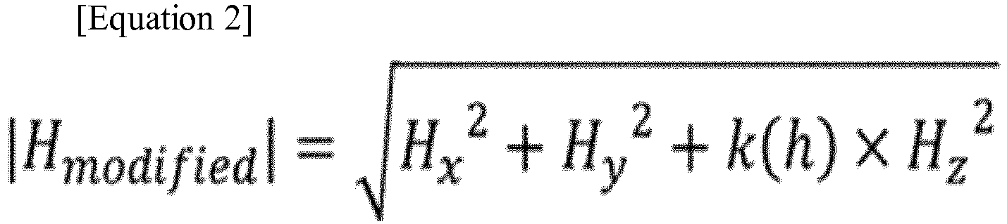
- the AP 710 may calculate the RSSI by applying, to a signal received from the coil in the z-axis direction, height information (h) from a specific position to an installation position of the AP 710 in order to modify the signal received from the coil in the z-axis direction, as shown in the following Equation 2.
- the specific position may be a position corresponding to, for example, the floor.
- H x 2 + H y 2 + k h ⁇ H z 2
- Equation 2 H modified denotes an RSSI for a magnetic field signal modified by the AP 710, k(h) denotes an empirical value according to the height information (h), which may be set differently depending on a place where the AP 710 is installed.
- the AP 710 may modify the magnetic field signal received from the terminal using the height information (h) from the specific position to the installation position of the AP and information about the orientation of the terminal, as shown in the following Equation 3.
- 1 + k h sin ⁇ ⁇
- H received denotes an RSSI for the magnetic field signal which the AP 710 receives from the terminal
- H modified denotes an RSSI for a magnetic field signal obtained such that the AP 710 modifies the height information (h) about the position of the API 710 and the information about the orientation of the terminal (i.e., horizontal level (degree) of the terminal and the ground).
- the AP 710 calculates the RSSI by modifying the magnetic field signal received from the terminal using Equation 2 and Equation 3, a probability that an error occurs in information about the calculated distance is lowered.
- FIG. 8 is a graph illustrating an error of a distance calculated by an AP based on an RSSI for the magnetic field signal modified according to FIG. 7 .
- a beacon 801 performs the function of the AP.
- the beacon 801 represents an error calculated by measuring the position of the terminal at intervals of about 4 m in the x-axis and about 2.5 m in the y-axis in the same manner as those in FIGS. 4 and 6 .
- the beacon 801 includes three coils as described above in FIG. 7 and calculates a modified RSSI using Equation 3.
- FIG. 9 shows a method in which a transmitter performs position estimation in a communication system according to an embodiment of the present disclosure.
- the transmitter may correspond to the terminal 100 requesting the position estimation.
- the transmitter detects an event requesting position estimation. For example, when recognizing that a specific application on which position estimation is required is executed or the transmitter enters a specific place, the transmitter may detect an event requesting position estimation. As another example, when the transmitter is a tag type terminal only for position estimation, the transmitter may detect an event requesting position estimation every predetermined period.
- the transmitter transmits a magnetic field signal generated from a coil to a receiver.
- the transmitter may transmit the magnetic field signal to the receiver, and at the same time, may also transmit information about an identifier of the transmitter to the receiver.
- the transmitter may transmit the information about the identifier of the transmitter to the receiver before transmitting the magnetic field signal, and may transmit, when receiving a signal transmission request from the receiver, the magnetic field signal to the receiver.
- the receiver can identify the transmitter in a method other than the above-described method.
- the transmitter receives a response message including the RSSI information and the position information from the receiver.
- the transmitter ascertains whether the RSSI information is included in the response message.
- the transmitter ascertains the position information included in the response message.
- the transmitter ascertains the RSSI information included in the response message, calculates a distance between the transmitter and the receiver based on the RSSI information, and performs position estimation according to the calculated distance information using a map stored therein.
- FIG. 10 shows a method in which a receiver performs position estimation in a communication system according to an embodiment of the present disclosure.
- the receiver may correspond to the AP 300 or the server 150 of FIG. 1 which receives a request for the position estimation.
- the receiver receives a magnetic field signal requesting position estimation from a transmitter.
- the magnetic field signal may be received through three coils included inside or outside the receiver, or may be received wirelessly from the three coils included in a separate infrastructure device (e.g., a beacon for localization).
- the receiver calculates an RSSI for the magnetic field signal using Equation 2 or Equation 3.
- the receiver has already received information (i.e., at least one piece of information of height information and orientation information) required in Equation 2 and Equation 3 from the transmitter.
- the receiver determines whether to transmit the measured RSSI information to the transmitter according to setting information of the communication system.
- the receiver transmits a response message including the measured RSSI information to the transmitter.
- the receiver calculates a distance between the transmitter and the receiver based on the measured RSSI information.
- the receiver estimates the position of the transmitter according to the calculated distance in a map stored therein. Accordingly, the receiver may transmit the response message including the estimated position information to the transmitter.
- the position estimation process between the receiver and the transmitter may be terminated when an end event for the position service is detected or when the transmitter leaves a specific place.
- FIG. 11 shows a detailed device configuration in which a transmitter according to an embodiment of the present disclosure performs position estimation.
- the transmitter may include a transmission unit 1111, a reception unit 1113, a control unit 1130, an input unit 1151, an output unit 1153, a storage unit 1170, and a signal generation unit 1190 in order to perform position estimation.
- the transmission unit 1111 and the reception unit 1113 may be configured as one transmission/reception unit 1110, and the input unit 1151 and the output unit 1153 may be also configured as one input/output unit 1150.
- the signal generation unit 1190 includes a coil having one axis according to an embodiment of the present disclosure.
- FIGS. 12A to 12C show a coil connected to a transmitter according to an embodiment of the present disclosure as one example.
- a coil 1201 is included in a metal frame 1203 configured outside the transmitter.
- the coil 1201 may connect a part of the coil 1201 to the metal frame 1203 to increase the area of the coil 1201 as shown in a section 1207 of FIG. 12B .
- the signal generation unit 1190 may further include a capacitor 1205 so that a magnetic field signal generated in the coil 1201 of the transmitter is accurately transmitted to the receiver.
- the capacitor 1205 is connected to the metal frame and operates as a repeater resonator to form a resonant loop at the same frequency F 0 as that of the coil 1201.
- the input unit 1151 detects an event requesting position estimation according to an embodiment of the present disclosure.
- the input unit 1151 may include a gyro sensor for measuring an angle between the transmitter and the receiver.
- the control unit 1130 controls the overall operation of the transmitter, and in particular, controls operations related to an operation of estimating the position by the transmitter according to an embodiment of the present disclosure.
- the operations related to the operation of estimating the position by the transmitter according to the embodiment of the present disclosure are the same as those described with reference to FIGS. 1 to 9 , and thus, a detailed description thereof will be omitted here.
- the transmission unit 1111 transmits various signals and various messages to the receiver under the control of the control unit 1130.
- the various signals and various messages transmitted by the transmission unit 1111 are the same as those described with reference to FIGS. 1 to 9 , and thus, a detailed description thereof will be omitted here.
- the reception unit 1113 receives various signals and various messages from the receiver under the control of the control unit 1130.
- the various signals and various messages received by the receiving unit 1113 are the same as those described with reference to FIGS. 1 to 9 , and thus, a detailed description thereof will be omitted here.
- the storage unit 1170 stores programs and a variety of information related to the operation of estimating the position by the transmitter according to the embodiment of the present disclosure under the control of the control unit 1130.
- the output unit 1153 outputs various signals and various messages related to the operation of estimating the position by the transmitter according to the embodiment of the present disclosure, under the control of the control unit 1130.
- the various signals and various messages output by the output unit 1153 are the same as those described with reference to FIGS. 1 to 9 , and thus, a detailed description thereof will be omitted here.
- FIG. 11 shows a case in which the transmitter is implemented with separate units such as the transmission/reception unit 1110, the control unit 1130, the input/output unit 1150, the storage unit 1170, and the signal generation unit 1190.
- the transmitter can be implemented in a form in which at least two of the transmission/reception unit 1110, the control unit 1130, the input/output unit 1150, the storage unit 1170, and the signal generation unit 1190 are integrated.
- the transmitter can be implemented as a single processor.
- FIG. 13 shows a detailed device configuration in which a receiver according to an embodiment of the present disclosure performs position estimation.
- the receiver may include a control unit 1310, a storage unit 1330, a transmission unit 1351, and a reception unit 1353 in order to receive a magnetic field signal from a transmitter and estimate the position of the transmitter.
- the transmission unit 1351 and the reception unit 1353 may be configured as one transmission/reception unit 1350.
- the control unit 1310 controls the overall operation of the receiver, and in particular, controls operations related to an operation of estimating the position by the receiver according to an embodiment of the present disclosure.
- the operations related to the operation of estimating the position by the receiver according to an embodiment of the present disclosure are those described with reference to FIGS. 1 to 10 , and thus a detailed description thereof will be omitted here.
- the transmission unit 1351 transmits various signals and various messages to the transmitter under the control of the control unit 1310.
- the various signals and various messages transmitted by the transmission unit 1351 are the same as those described with reference to FIGS. 1 to 10 , and thus, a detailed description thereof will be omitted here.
- reception unit 1353 receives various signals and various messages from the transmitter under the control of the control unit 1310.
- the various signals and various messages received by the reception unit 1353 are the same as those described with reference to FIGS. 1 to 10 , and thus, a detailed description thereof will be omitted here.
- the storage unit 1330 stores programs and a variety of information related to the operation of estimating the position by the receiver according to an embodiment of the present disclosure, under the control of the control unit 1310. In addition, the storage unit 1330 stores the various signals and various messages which the reception unit 1353 receives from the transmitter.
- FIG. 13 shows a case in which the receiver is implemented with separate units such as the transmission/reception unit 1350, the control unit 1310, and the storage unit 1330.
- the receiver can be implemented in a form in which at least two of the transmission/reception unit 1350, the control unit 1310, and the storage unit 1330 are integrated.
- the transmitter can be implemented as a single processor.
- the transmitter may be provided with position-based service information based on precisely estimated position information from the receiver according to the embodiment of the present disclosure.
- the position-based service includes an indoor navigation service, a position-based advertisement service, a product information service, an acquaintance finding service, and a missing child (distress) location finding service, and the like.
- the receiver according to the embodiment of the present disclosure can effectively provide an asset management service, a position-based service for staff management, and the like to a manager terminal managing the transmitter.
Landscapes
- Engineering & Computer Science (AREA)
- Physics & Mathematics (AREA)
- Computer Networks & Wireless Communication (AREA)
- Signal Processing (AREA)
- Radar, Positioning & Navigation (AREA)
- Remote Sensing (AREA)
- General Physics & Mathematics (AREA)
- Electromagnetism (AREA)
- Optics & Photonics (AREA)
- Spectroscopy & Molecular Physics (AREA)
- High Energy & Nuclear Physics (AREA)
- Condensed Matter Physics & Semiconductors (AREA)
- Automation & Control Theory (AREA)
- Position Fixing By Use Of Radio Waves (AREA)
- Mobile Radio Communication Systems (AREA)
Abstract
Description
- The present disclosure generally relates to a method and apparatus for estimating a position in a communication system, and more particularly, to a method and apparatus for estimating a position of a terminal based on a magnetic field signal.
- Efforts have been made to develop an improved 5th-Generation (5G) communication system or a pre-5G communication system to meet the increasing demand for wireless data traffic after the commercialization of 4th-Generation (4G) communication system. For this reason, the 5G communication system or the pre-5G communication system is called a beyond 4G network communication system after 4G network or a post LTE system after an LTE system.
- In order to achieve a higher data transmission rate, 5G communication systems are being considered for implementation in ultra-high frequency (mmWave) bands (for example, 60 GHz bands). In order to mitigate the path loss of radio waves in the ultra-high frequency bands and to increase the propagation distance of the radio waves, in the 5G communication system, beamforming, massive multi-input multi-output (massive MIMO), Full Dimensional MIMO (FD-MIMO), array antenna, analog beamforming, and large scale antenna technologies are being discussed.
- In addition, in order to improve the network of a system, in the 5G communication system, technologies such as an evolved small cell, an advanced small cell, a cloud radio access network (cloud RAN), an ultra-dense network, Device to Device communication (D2D), wireless backhaul, a moving network, cooperative communication, Coordinated Multi-Points (CoMP), interference cancellation, and the like are being developed.
- In addition in the 5G system, Hybrid FSK and QAM Modulation (FQAM) and Sliding Window Superposition Coding (SWSC), which are Advanced Coding Modulation (ACM) schemes, Filter Bank Multi-Carrier (FBMC), non-orthogonal multiple access (NOMA), and sparse code multiple access (SCMA), which are advanced access schemes, and the like are being developed.
- On the other hand, the Internet has evolved into an Internet of Things (IoT) network in which information is exchanged between distributed components such as objects, in a human-centered connection network where humans generate and consume information. Internet of Everything (IoE) technology, which combines IoT technology with big data processing technology through connection with cloud servers, is also emerging. In order to implement IoT, technology elements such as sensing technology, wired/wireless communication, network infrastructure, service interface technology, and security technology are required. In recent years, technologies such as sensor network, Machine to Machine (M2M), Machine Type Communication (MTC), etc., for connection between objects have been studied. In an IoT environment, an intelligent Internet Technology (IT) service can be provided that collects and analyzes data generated from connected objects to create new value in human life. IoT can be applied to fields such as smart home, smart building, smart city, smart car or connected car, smart grid, health care, smart home appliance, advanced medical service, etc., through the convergence and combination of existing information technology (IT) and various industries.
- Accordingly, various attempts have been made to apply the 5G communication system to the IoT network. For example, technologies such as a sensor network, M2M, MTC, etc., are implemented by the 5G communication technologies such as beamforming, MIMO, array antenna, etc. The application of the cloud RAN as the above-described big data processing technology may be an example of the convergence of 5G technology and IoT technology.
- Recently, position-based services using the position of a terminal have attracted much attention due to the rapid spread of smart terminals. The position estimation in an indoor environment can be utilized in various ways such as position awareness and route guidance of a terminal within a large building or shopping mall, guidance to the position of a parked car in a large parking lot, rescue inside a large building in case of disaster such as fire or earthquake, and the like.
- In such an indoor environment, the accuracy of the position estimation of the terminal is highly likely to be degraded due to interference signals to people and surrounding obstacles. Therefore, in order to secure the accuracy of a short distance (for example, 5 m) in a communication system, a plurality of Access Points (APs) must be installed within a certain range (for example, 10 m). However, when a plurality of APs is installed in the communication system, the installation cost increases and an algorithm for estimating the position of the terminal may be complicated. Therefore, there is a need for a method of increasing the accuracy of the position estimation of a terminal using one AP in a communication system.
- According to aspects of the present disclosure, a method and apparatus for estimating a position of a terminal based on a magnetic field signal are provided.
- In addition, according to aspects of the present disclosure, a method and apparatus for estimating a position of a terminal including a coil for generating a magnetic field signal in a communication system using the terminal and an access point (AP) are provided.
- In accordance with an aspect of the present disclosure, a method in which a transmitter performs position estimation in a communication system, includes: transmitting a magnetic field signal generated from one coil included in the transmitter to a receiver; and receiving position information of the transmitter estimated based on a Received Signal Strength (RSS) of the magnetic field signal from the receiver.
- In accordance with another aspect of the present disclosure, a method in which a receiver performs position estimation in a communication system, includes: receiving a magnetic field signal from a transmitter through three coils having directions orthogonal to each other; measuring an RSS of the magnetic field signal; estimating a position of the transmitter based on the RSS; and transmitting information about the estimated position to the transmitter.
- In accordance with still another aspect of the present disclosure, a transmitter of which a position is estimated in a communication system includes: a control unit that controls a magnetic field signal generated from one coil included in the transmitter to be transmitted to a receiver and ascertains position information estimated based on an RSS of the magnetic field signal received from the receiver; and a transmission/reception unit that transmits the magnetic field signal to the receiver and receives the position information from the receiver.
- In accordance with yet another aspect of the present disclosure, a receiver that estimates a position of a transmitter in a communication system includes: a reception unit that receives a magnetic field signal through three coils having different directions; a control unit that measures an RSS of the magnetic field signal and estimates the position of the transmitter based on the RSS; and a transmission unit that transmits information about the estimated position to the transmitter.
- The above and other aspects, features and advantages of the present disclosure will be more apparent from the following detailed description taken in conjunction with the accompanying drawings, in which:
-
FIG. 1 illustrates a configuration of a communication system according to an embodiment of the present disclosure; -
FIG. 2 is a graph illustrating distance information calculated in accordance with the orientation of a terminal according to an embodiment of the present disclosure; -
FIGS. 3 to 6 are diagrams illustrating an example in which an Access Point (AP) receives a magnetic field signal in accordance with the orientation of a terminal in a communication system according to an embodiment of the present disclosure; -
FIG. 7 is a diagram illustrating an example in which three coils are attached to a ceiling existing in a room according to an embodiment of the present disclosure; -
FIG. 8 is a diagram illustrating a probability that an error is generated in distance information when an AP measures a Received Signal Strength Indication (RSSI) by modifying a magnetic field signal received from a terminal according to an embodiment of the present disclosure; -
FIG. 9 is a diagram illustrating a method in which a transmitter performs position estimation in a communication system according to an embodiment of the present disclosure; -
FIG. 10 is a diagram illustrating a method in which a receiver performs position estimation in a communication system according to an embodiment of the present disclosure; -
FIG. 11 is a diagram illustrating a detailed device configuration in which a transmitter according to an embodiment of the present disclosure performs position estimation; -
FIGS. 12A to 12C are diagrams illustrating embodiments in which a coil is connected to a transmitter according to an embodiment of the present disclosure; and -
FIG. 13 is a diagram illustrating a detailed device configuration in which a receiver according to an embodiment of the present disclosure performs position estimation. - Hereinafter, an exemplary embodiment of the present disclosure will be described in detail with reference to the accompanying drawings. In the following description, it should be noted that only portions required for comprehension of operations according to the embodiments of the present disclosure will be described and descriptions of other portions will be omitted not to make subject matters of the present disclosure obscure.
- The main point of the present disclosure is that each of a transmitter and a receiver transmits and receives a magnetic field signal using a coil and the receiver estimates a position of a terminal (i.e., transmitter) based on Received Signal Strength (RSS) of the magnetic field signal.
- To this end, a method and apparatus for estimating a position of a terminal in a communication system according to an embodiment of the present disclosure will be described in detail.
-
FIG. 1 illustrates a configuration of a communication system according to an embodiment of the present disclosure. - Referring to
FIG. 1 , the communication system according to an embodiment of the present disclosure includes aterminal 100, an Access Point (AP) 130, and aserver 150. Here, theterminal 100 may be implemented as a transmitter, and the AP 130 and theserver 150 may be implemented as a receiver as a single unit. Theserver 150 may be a position estimation server. - The
terminal 100 includes a coil (inductor) 110 for generating a magnetic field signal in an internal transmission module. Here, thecoil 110 is used for Near Field Communication (NFC) and Wireless Power Transfer (WPT), and resonates at a specific frequency f0. Here, theterminal 100 may be a terminal capable of data and voice communication such as in a cellular phone, or a terminal (e.g., a tag type terminal) that performs only position estimation. - When detecting an event requesting position estimation, the
terminal 100 transmits a magnetic field signal generated from thecoil 110 to theAP 130. - At this time, the
terminal 100 may detect an event requesting the position estimation according to predetermined information. For example, when theterminal 100 recognizes that a specific application (app) requiring position estimation is executed or it has entered a specific place, theterminal 100 may detect an event requesting position estimation. As another example, when theterminal 100 is a tag type terminal only for position estimation, theterminal 100 may detect an event requesting position estimation every predetermined period. - In order to notify the
AP 130 that the magnetic field signal transmitted to theAP 130 belongs to theterminal 100, theterminal 100 may transmit the magnetic field signal to theAP 130, and at the same time, may also transmit information on an identifier of theterminal 100 to theAP 130. As another example, theterminal 100 may transmit the information on the identifier of theterminal 100 to theAP 130 before transmitting the magnetic field signal, and may transmit, when receiving a signal transmission request from theAP 130, the magnetic field signal to theAP 130. Obviously, the AP 130 can identify theterminal 100 in a method other than the above-described method. - The AP 130 receives the magnetic field signal from the
terminal 100 through threecoils coils coils coils AP 130 or may be connected to (that is, attached to) the outside. Alternatively, only some of the three coils may be included in theAP 130 or may be connected to the outside. - The
AP 130 may calculate a received signal strength indication (RSSI) of the magnetic field signal received from the terminal 100 based on the magnetic field signals received from the respective directions. For example, theAP 130 may calculate the RSSI based on the magnetic field signals received in each direction as shown inEquation 1 below.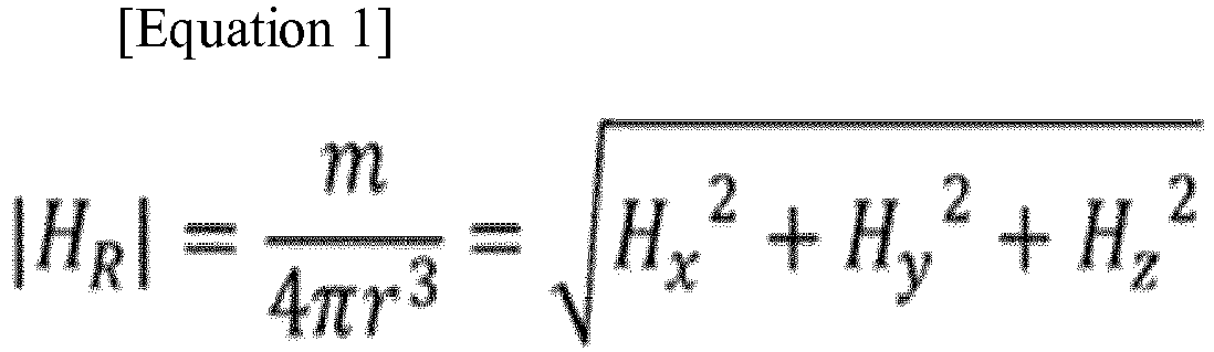
- In
Equation 1, HR denotes an RSSI of the magnetic field signal received from the terminal 100, Hx denotes a signal received through the coil in the x-axis direction, Hy denotes a signal received through the coil in the y-axis direction, and Hz denotes a signal received through the coil in the z-axis direction. - The
AP 130 transmits information about the RSSI to theserver 150 or the terminal 100. In this case, when the terminal 100 receives the RRSI information from theAP 130, it is possible to estimate the position of the terminal 100 in the same manner as that in theserver 150. - The
server 150 receives the measured RSSI information from theAP 130 and calculates a distance between the terminal 100 and theAP 130 according to the received RSSI information. Next, theserver 150 estimates the position of the terminal 100 using information about the calculated distance and information about a built-in map. Here, when estimating the position of the terminal 100, theserver 150 may more accurately estimate the position of the terminal 100 using information for position estimation received from another AP other than theAP 130. Theserver 150 transmits information about the estimated position of the terminal 100 to the terminal 100. - Meanwhile, the RSSI information measured from
Equation 1 in theAP 130 is information that does not consider a direction between theAP 130 and the terminal 100. When theserver 150 calculates the distance between theAP 130 and the terminal 100 using the RSSI information that does not consider the direction between theAP 130 and the terminal 100, an error may occur in calculating the distance. - For example,
FIG. 2 is a graph illustrating distance information calculated in accordance with the orientation of a terminal according to an embodiment of the present disclosure. - In
FIG. 2 , an angle (theta) between the terminal (i.e., transmitter) and the AP (i.e., receiver) varies depending on the orientation of the terminal. - Referring to
FIG. 2 , when a distance between theAP 130 and the terminal 100 is calculated by changing the orientation of the terminal, it can be confirmed that a distance error of up to 13 % may be generated according to the orientation of the terminal. Accordingly, in order to improve the accuracy of position estimation, an embodiment of the present disclosure proposes a method and an apparatus in which theAP 130 measures an RSSI in consideration of a direction between the terminal 100 and theAP 130. - For example, objects through which a magnetic field signal cannot be transmitted in an indoor environment may be a ceiling and a floor. In this case, the
AP 130 cannot receive the magnetic field signal transmitted by the terminal 100 as it is, but may receive the magnetic field signal deformed (i.e., including an interference signal) by the ceiling or floor in which theAP 130 is installed. That is, as shown inFIGS. 3 and5 , when even thesame terminal 100 is connected to theAP 130 in a different direction, theAP 130 may receive another magnetic field signal. -
FIGS. 3 and6 show an example in which an AP receives a magnetic field signal according to the orientation of a terminal in a communication system according to an embodiment of the present disclosure. InFIGS. 3 to 6 , the AP includes only a coil in the z-axis direction. - Referring to
FIG. 3 , when a terminal 310 is positioned perpendicular to the ceiling in a room, the magnetic field signal of the terminal 310 is transmitted to anAP 320 through an XY plane, so that theAP 320 can receive the magnetic field signal transmitted from the terminal 310 through the XY plane. In this case, since the magnetic field signal transmitted from the terminal 310 does not pass through a z-axis plane, the AP does not receive interference caused by the ceiling above a certain threshold value. From this, when the terminal 310 is positioned perpendicular to the ceiling, theAP 320 may receive the magnetic field signal having a low deformation rate among the magnetic field signals transmitted from the terminal 310. Accordingly, since theAP 320 calculates the RSSI using the magnetic field signal having a low deformation rate which is almost the same as the magnetic field signal from the terminal 310, a probability that an error occurs in the distance information calculated based on the RSSI may be lower than a predetermined threshold value. -
FIG. 4 is a graph illustrating an error of a distance calculated based on the RSSI by the AP when a terminal is positioned perpendicular to the ceiling in a door as shown inFIG. 3 . - In
FIG. 4 , abeacon 401 performs the function of the AP.FIG. 4 shows an error calculated by measuring the position of the terminal between a table 405 and thebeacon 401 at intervals of about 4 m in the x-axis and about 2.5 m in the y-axis. Referring toFIG. 4 , errors of the distance calculated by thebeacon 401 based on the RSSI are all 5 m or less, except for onespecific point 403. In other words, according to the present disclosure, it is possible to perform position estimation with an error of 5 m or less only using one receiver, that is, thebeacon 401, in an area of 27.5 m x 13.1 m. - However, as shown in
FIG. 5 , when the terminal 510 is positioned in parallel with the ceiling in a room, the magnetic field signal of the terminal 510 is transmitted to anAP 520 through an XZ plane or an YZ plane, so that theAP 520 may receive the magnetic field signal transmitted from the terminal 510 through the XZ plane or the YZ plane. In this case, since the magnetic field signal transmitted from the terminal 510 passes through a Z-axis plane, theAP 520 may receive interference caused by the ceiling above a predetermined threshold value. From this, when the terminal 510 is positioned in parallel with the ceiling, theAP 520 may receive the magnetic field signal having a high deformation rate among the magnetic field signals transmitted from the terminal 510. Accordingly, since theAP 520 calculates the RSSI using the magnetic field signal having a high deformation rate among the magnetic field signals transmitted from the terminal 510, a probability that an error occurs in the distance information calculated based on the RSSI may be higher than a predetermined threshold value. -
FIG. 6 is a graph illustrating an error of a distance calculated based on the RSSI by the AP when a terminal is positioned in parallel with the ceiling in a room as shown inFIG. 5 . - In
FIG. 6 , abeacon 601 performs the function of the AP. Thebeacon 601 represents an error calculated by measuring the position of the terminal at intervals of about 4 m in the x-axis and about 2.5 m in the y-axis in the same manner as that inFIG. 4 . Referring toFIG. 6 , an error of a distance calculated based on the RSSI by thebeacon 601 is 5 m or more at 50% or more of the number of measured terminals. - Accordingly, the
AP 520 according to the embodiment of the present disclosure may estimate an accurate position of the terminal 510 by measuring the RSSI after modifying the magnetic field signal received from the terminal 510 to be the same as the magnetic field signal transmitted by theterminal 510. - To this end, hereinafter, an example in which three coils are attached to a ceiling existing in a room will be described, and a method in which the
AP 520 calculates the RSSI by modifying the received magnetic field signal will be described. -
FIG. 7 is a diagram illustrating an example in which three coils are attached to a ceiling existing in a room according to an embodiment of the present disclosure. - In the embodiment of
FIG. 7 , it is assumed that the three coils are attached to the ceiling, but obviously, the embodiment of the present disclosure can be applied to a case in which the coils are attached to a floor. - Referring to
FIG. 7 , acoil 701 in an x-axis direction and acoil 703 in a y-axis direction may be included in an AP 710, and acoil 705 in a z-axis direction may be connected to the outside of the AP 710. - Specifically, the
coil 705 in the z-axis direction is a sheet type coil in the z-axis having a tile size of a ceiling, and may be configured to occupy a larger area than the AP 710. Thecoil 705 in the z-axis direction may be installed to be included in a ceiling tile or may be installed as a transparent sheet on a tile surface. As another example, thecoil 705 in the z-axis direction may be attached to a ferrite sheet attached to the ceiling. - The
coil 701 in the x-axis direction and thecoil 703 in the y-axis direction included in the AP 710 may be installed on each of two orthogonal ferrite rods. - The AP 710 may receive a magnetic field signal from a terminal using the three coils configured as shown in the embodiment of
FIG. 7 . - As described above, the AP 710 measures the RSSI after modifying the magnetic field signal received from the terminal, taking into consideration that the magnetic field signal received from the terminal may be deformed.
- As an example, the AP 710 according to the embodiment of the present disclosure may calculate the RSSI by applying, to a signal received from the coil in the z-axis direction, height information (h) from a specific position to an installation position of the AP 710 in order to modify the signal received from the coil in the z-axis direction, as shown in the following Equation 2. Here, the specific position may be a position corresponding to, for example, the floor.
- In Equation 2, Hmodified denotes an RSSI for a magnetic field signal modified by the AP 710, k(h) denotes an empirical value according to the height information (h), which may be set differently depending on a place where the AP 710 is installed.
- As another example, when the AP 710 according to the embodiment of the present disclosure receives, from the terminal, direction information (i.e., an angle) about the direction between the terminal and the AP 710, the AP 710 may modify the magnetic field signal received from the terminal using the height information (h) from the specific position to the installation position of the AP and information about the orientation of the terminal, as shown in the following Equation 3.

- In Equation 3, Hreceived denotes an RSSI for the magnetic field signal which the AP 710 receives from the terminal, Hmodified denotes an RSSI for a magnetic field signal obtained such that the AP 710 modifies the height information (h) about the position of the API 710 and the information about the orientation of the terminal (i.e., horizontal level (degree) of the terminal and the ground).
- As described above, when the AP 710 calculates the RSSI by modifying the magnetic field signal received from the terminal using Equation 2 and Equation 3, a probability that an error occurs in information about the calculated distance is lowered.
-
FIG. 8 is a graph illustrating an error of a distance calculated by an AP based on an RSSI for the magnetic field signal modified according toFIG. 7 . - In
FIG. 8 , abeacon 801 performs the function of the AP. Thebeacon 801 represents an error calculated by measuring the position of the terminal at intervals of about 4 m in the x-axis and about 2.5 m in the y-axis in the same manner as those inFIGS. 4 and6 . - The
beacon 801 includes three coils as described above inFIG. 7 and calculates a modified RSSI using Equation 3. - Referring to
FIG. 8 , when thebeacon 801 uses the RSSI information calculated from Equation 3, it can be seen that the error has been significantly reduced compared toFIG. 6 . -
FIG. 9 shows a method in which a transmitter performs position estimation in a communication system according to an embodiment of the present disclosure. Referring toFIG. 9 , the transmitter may correspond to the terminal 100 requesting the position estimation. - Referring to
FIG. 9 , inoperation 901, the transmitter detects an event requesting position estimation. For example, when recognizing that a specific application on which position estimation is required is executed or the transmitter enters a specific place, the transmitter may detect an event requesting position estimation. As another example, when the transmitter is a tag type terminal only for position estimation, the transmitter may detect an event requesting position estimation every predetermined period. - Next, in
operation 903, the transmitter transmits a magnetic field signal generated from a coil to a receiver. At this time, in order to notify the receiver that the transmitted magnetic field signal belongs to the transmitter, the transmitter may transmit the magnetic field signal to the receiver, and at the same time, may also transmit information about an identifier of the transmitter to the receiver. As another example, the transmitter may transmit the information about the identifier of the transmitter to the receiver before transmitting the magnetic field signal, and may transmit, when receiving a signal transmission request from the receiver, the magnetic field signal to the receiver. In addition, obviously, the receiver can identify the transmitter in a method other than the above-described method. - Next, in
operation 905, the transmitter receives a response message including the RSSI information and the position information from the receiver. Next, inoperation 907, the transmitter ascertains whether the RSSI information is included in the response message. Inoperation 909, when the RSSI information is not included in the response message (i.e., when the position information is included), the transmitter ascertains the position information included in the response message. On the other hand, inoperation 911, when the RSSI information is included in the response message, the transmitter ascertains the RSSI information included in the response message, calculates a distance between the transmitter and the receiver based on the RSSI information, and performs position estimation according to the calculated distance information using a map stored therein. -
FIG. 10 shows a method in which a receiver performs position estimation in a communication system according to an embodiment of the present disclosure. - Here, the receiver may correspond to the AP 300 or the
server 150 ofFIG. 1 which receives a request for the position estimation. - Referring to
FIG. 10 , inoperation 1001, the receiver receives a magnetic field signal requesting position estimation from a transmitter. Here, the magnetic field signal may be received through three coils included inside or outside the receiver, or may be received wirelessly from the three coils included in a separate infrastructure device (e.g., a beacon for localization). - Next, in
operation 1003, the receiver calculates an RSSI for the magnetic field signal using Equation 2 or Equation 3. Here, it is assumed that the receiver has already received information (i.e., at least one piece of information of height information and orientation information) required in Equation 2 and Equation 3 from the transmitter. - Next, in
operation 1005, the receiver determines whether to transmit the measured RSSI information to the transmitter according to setting information of the communication system. Inoperation 1007, when the receiver determines to transmit the measured RSSI information to the transmitter, the receiver transmits a response message including the measured RSSI information to the transmitter. On the other hand, inoperation 1009, when the receiver determines not to transmit the measured RSSI information to the transmitter, the receiver calculates a distance between the transmitter and the receiver based on the measured RSSI information. Next, inoperation 1011, the receiver estimates the position of the transmitter according to the calculated distance in a map stored therein. Accordingly, the receiver may transmit the response message including the estimated position information to the transmitter. - Meanwhile, the position estimation process between the receiver and the transmitter according to an embodiment of the present disclosure may be terminated when an end event for the position service is detected or when the transmitter leaves a specific place.
-
FIG. 11 shows a detailed device configuration in which a transmitter according to an embodiment of the present disclosure performs position estimation. - Referring to
FIG. 11 , the transmitter may include atransmission unit 1111, areception unit 1113, acontrol unit 1130, aninput unit 1151, anoutput unit 1153, astorage unit 1170, and asignal generation unit 1190 in order to perform position estimation. Here, thetransmission unit 1111 and thereception unit 1113 may be configured as one transmission/reception unit 1110, and theinput unit 1151 and theoutput unit 1153 may be also configured as one input/output unit 1150. - First, the
signal generation unit 1190 includes a coil having one axis according to an embodiment of the present disclosure. -
FIGS. 12A to 12C show a coil connected to a transmitter according to an embodiment of the present disclosure as one example. - Referring to
FIG. 12A , acoil 1201 is included in ametal frame 1203 configured outside the transmitter. Referring toFIG. 12B , thecoil 1201 may connect a part of thecoil 1201 to themetal frame 1203 to increase the area of thecoil 1201 as shown in asection 1207 ofFIG. 12B . In addition, referring toFIG. 12C , thesignal generation unit 1190 may further include acapacitor 1205 so that a magnetic field signal generated in thecoil 1201 of the transmitter is accurately transmitted to the receiver. Thecapacitor 1205 is connected to the metal frame and operates as a repeater resonator to form a resonant loop at the same frequency F0 as that of thecoil 1201. - The
input unit 1151 detects an event requesting position estimation according to an embodiment of the present disclosure. Theinput unit 1151 may include a gyro sensor for measuring an angle between the transmitter and the receiver. - The
control unit 1130 controls the overall operation of the transmitter, and in particular, controls operations related to an operation of estimating the position by the transmitter according to an embodiment of the present disclosure. Here, the operations related to the operation of estimating the position by the transmitter according to the embodiment of the present disclosure are the same as those described with reference toFIGS. 1 to 9 , and thus, a detailed description thereof will be omitted here. - The
transmission unit 1111 transmits various signals and various messages to the receiver under the control of thecontrol unit 1130. Here, the various signals and various messages transmitted by thetransmission unit 1111 are the same as those described with reference toFIGS. 1 to 9 , and thus, a detailed description thereof will be omitted here. - In addition, the
reception unit 1113 receives various signals and various messages from the receiver under the control of thecontrol unit 1130. Here, the various signals and various messages received by the receivingunit 1113 are the same as those described with reference toFIGS. 1 to 9 , and thus, a detailed description thereof will be omitted here. - The
storage unit 1170 stores programs and a variety of information related to the operation of estimating the position by the transmitter according to the embodiment of the present disclosure under the control of thecontrol unit 1130. - The
output unit 1153 outputs various signals and various messages related to the operation of estimating the position by the transmitter according to the embodiment of the present disclosure, under the control of thecontrol unit 1130. Here, the various signals and various messages output by theoutput unit 1153 are the same as those described with reference toFIGS. 1 to 9 , and thus, a detailed description thereof will be omitted here. - Meanwhile,
FIG. 11 shows a case in which the transmitter is implemented with separate units such as the transmission/reception unit 1110, thecontrol unit 1130, the input/output unit 1150, thestorage unit 1170, and thesignal generation unit 1190. However, obviously, the transmitter can be implemented in a form in which at least two of the transmission/reception unit 1110, thecontrol unit 1130, the input/output unit 1150, thestorage unit 1170, and thesignal generation unit 1190 are integrated. In addition, the transmitter can be implemented as a single processor. -
FIG. 13 shows a detailed device configuration in which a receiver according to an embodiment of the present disclosure performs position estimation. - Referring to
FIG. 13 , the receiver may include acontrol unit 1310, astorage unit 1330, atransmission unit 1351, and areception unit 1353 in order to receive a magnetic field signal from a transmitter and estimate the position of the transmitter. Here, thetransmission unit 1351 and thereception unit 1353 may be configured as one transmission/reception unit 1350. - The
control unit 1310 controls the overall operation of the receiver, and in particular, controls operations related to an operation of estimating the position by the receiver according to an embodiment of the present disclosure. The operations related to the operation of estimating the position by the receiver according to an embodiment of the present disclosure are those described with reference toFIGS. 1 to 10 , and thus a detailed description thereof will be omitted here. - The
transmission unit 1351 transmits various signals and various messages to the transmitter under the control of thecontrol unit 1310. Here, the various signals and various messages transmitted by thetransmission unit 1351 are the same as those described with reference toFIGS. 1 to 10 , and thus, a detailed description thereof will be omitted here. - In addition, the
reception unit 1353 receives various signals and various messages from the transmitter under the control of thecontrol unit 1310. The various signals and various messages received by thereception unit 1353 are the same as those described with reference toFIGS. 1 to 10 , and thus, a detailed description thereof will be omitted here. - The
storage unit 1330 stores programs and a variety of information related to the operation of estimating the position by the receiver according to an embodiment of the present disclosure, under the control of thecontrol unit 1310. In addition, thestorage unit 1330 stores the various signals and various messages which thereception unit 1353 receives from the transmitter. - Meanwhile,
FIG. 13 shows a case in which the receiver is implemented with separate units such as the transmission/reception unit 1350, thecontrol unit 1310, and thestorage unit 1330. However, obviously, the receiver can be implemented in a form in which at least two of the transmission/reception unit 1350, thecontrol unit 1310, and thestorage unit 1330 are integrated. In addition, obviously, the transmitter can be implemented as a single processor. - Therefore, the transmitter may be provided with position-based service information based on precisely estimated position information from the receiver according to the embodiment of the present disclosure. Here, the position-based service includes an indoor navigation service, a position-based advertisement service, a product information service, an acquaintance finding service, and a missing child (distress) location finding service, and the like. In addition, when the transmitter is composed of a tag, the receiver according to the embodiment of the present disclosure can effectively provide an asset management service, a position-based service for staff management, and the like to a manager terminal managing the transmitter.
- While the present disclosure has been shown and described with reference to certain embodiments thereof, it will be understood by those skilled in the art that various changes in form and details may be made therein without departing from the scope of the present disclosure. Therefore, the scope of the present disclosure should not be defined as being limited to the aforementioned embodiments, but should be defined by the appended claims and equivalents thereof.
Claims (14)
- A method in which a transmitter performs position estimation in a communication system, comprising:transmitting a magnetic field signal generated from one coil included in the transmitter to a receiver; andreceiving position information of the transmitter estimated based on a Received Signal Strength (RSS) of the magnetic field signal from the receiver.
- The method of claim 1, wherein the RSS is received and measured through three coils having directions in which the magnetic field signals are orthogonal to each other.
- The method of claim 1, wherein the RSS is modified based on a height of the receiver.
- The method of claim 3, wherein the RSS is modified based on information about a horizontal level between the transmitter and the ground.
- The method of claim 1, further comprising:
transmitting information about a horizontal level between the transmitter and the ground. - The method of claim 1, wherein the magnetic field signal is a signal generated from a capacitor provided between the coil and a metal frame configured outside the transmitter.
- The method of claim 6, wherein a resonance by the metal frame and the capacitor structure has the same resonance frequency as that of the coil.
- A method in which a receiver performs position estimation in a communication system, comprising:receiving a magnetic field signal from a transmitter through three coils having directions orthogonal to each other;measuring an RSS of the magnetic field signal;estimating a position of the transmitter based on the RSS; andtransmitting information about the estimated position to the transmitter.
- The method of claim 8, wherein the estimating of the position of the transmitter includes estimating the position of the transmitter by modifying the magnetic field signal based on a height in which the receiver is installed from a specific position.
- The method of claim 8, wherein the estimating of the position of the transmitter includes estimating the position of the transmitter by modifying the magnetic field signal based on information about a horizontal level between the transmitter and the ground.
- The method of claim 8, further comprising:
receiving information about a horizontal level between the transmitter and the ground. - The method of claim 8, wherein the magnetic field signal is a signal generated from a coil and a capacitor included in the transmitter.
- A transmitter that operates according to any one of claims 1 to 7.
- A receiver that operates according to any one of claims 8 to 12.
Applications Claiming Priority (2)
| Application Number | Priority Date | Filing Date | Title |
|---|---|---|---|
| KR1020150119641A KR102348926B1 (en) | 2015-08-25 | 2015-08-25 | Method and apparatus for estimating location in communication system |
| PCT/KR2016/009452 WO2017034348A1 (en) | 2015-08-25 | 2016-08-25 | Method and apparatus for estimating position in wireless communication system |
Publications (2)
| Publication Number | Publication Date |
|---|---|
| EP3339891A1 true EP3339891A1 (en) | 2018-06-27 |
| EP3339891A4 EP3339891A4 (en) | 2018-09-19 |
Family
ID=58100546
Family Applications (1)
| Application Number | Title | Priority Date | Filing Date |
|---|---|---|---|
| EP16839636.4A Ceased EP3339891A4 (en) | 2015-08-25 | 2016-08-25 | Method and apparatus for estimating position in wireless communication system |
Country Status (4)
| Country | Link |
|---|---|
| US (1) | US11089564B2 (en) |
| EP (1) | EP3339891A4 (en) |
| KR (1) | KR102348926B1 (en) |
| WO (1) | WO2017034348A1 (en) |
Family Cites Families (39)
| Publication number | Priority date | Publication date | Assignee | Title |
|---|---|---|---|---|
| JP2002340504A (en) | 2001-05-15 | 2002-11-27 | Japan Science & Technology Corp | Magnetic position detection method and device |
| AU2002365033A1 (en) * | 2001-10-25 | 2003-06-17 | The Johns Hopkins University | Wide area metal detection (wamd) system and method for security screening crowds |
| JP4531683B2 (en) * | 2005-11-16 | 2010-08-25 | パナソニック株式会社 | Wireless communication apparatus and ad hoc route information acquisition method |
| KR100848322B1 (en) * | 2006-12-08 | 2008-07-24 | 한국전자통신연구원 | Indoor wireless positioning device and method |
| JP2008224489A (en) * | 2007-03-14 | 2008-09-25 | Yamatake Corp | Position estimation device |
| KR20080105805A (en) * | 2007-06-01 | 2008-12-04 | 엘지전자 주식회사 | Position tracking system using magnetic field |
| WO2008146492A1 (en) * | 2007-06-01 | 2008-12-04 | Panasonic Corporation | Communication system, wireless communication terminal device, position estimation device, communication relay device and connecting station |
| JP5611710B2 (en) * | 2009-08-12 | 2014-10-22 | 株式会社東芝 | Magnetic resonance imaging system |
| DE102009049672A1 (en) * | 2009-10-16 | 2011-04-28 | Fraunhofer-Gesellschaft zur Förderung der angewandten Forschung e.V. | Concept for generating experiences to update a reference database |
| EP2504662B1 (en) * | 2009-11-24 | 2018-11-21 | Nokia Technologies Oy | Positioning a device relative to a magnetic signal source |
| JP4736070B2 (en) | 2009-11-25 | 2011-07-27 | アイチ・マイクロ・インテリジェント株式会社 | Portable navigation system |
| US9151822B2 (en) * | 2009-12-31 | 2015-10-06 | Optimal Ranging, Inc. | Precise positioning using a distributed sensor network |
| US9544868B2 (en) * | 2010-01-07 | 2017-01-10 | Nec Corporation | Radio communication system, radio terminal, radio network, radio communication method and program |
| EP2564403B1 (en) * | 2010-04-30 | 2016-09-21 | Powermat Technologies Ltd. | System and method for transfering power inductively over an extended region |
| KR101140338B1 (en) | 2010-11-01 | 2012-05-03 | 한국전기연구원 | Resonant coil structure for wireless power transfer |
| US9166562B2 (en) * | 2013-02-25 | 2015-10-20 | Qualcomm Incorporated | Impedance transformation network for improved driver circuit performance |
| US8855671B1 (en) * | 2011-03-28 | 2014-10-07 | Google Inc. | System and method for determining position |
| KR101833217B1 (en) | 2011-12-07 | 2018-03-05 | 삼성전자주식회사 | Mobile terminal device for positioning system based on magnetic map and positioning method using the device |
| FI124153B (en) | 2012-01-11 | 2014-04-15 | Indooratlas Oy | Use of magnetic field-based navigation |
| US8683707B1 (en) * | 2012-03-28 | 2014-04-01 | Mike Alexander Horton | Magnetically modulated location system |
| US20130282438A1 (en) * | 2012-04-24 | 2013-10-24 | Qualcomm Incorporated | System for delivering relevant user information based on proximity and privacy controls |
| KR20150024880A (en) * | 2012-06-05 | 2015-03-09 | 넥스트나브, 엘엘씨 | Systems and methods for location positioning of user device |
| KR101436031B1 (en) | 2012-10-22 | 2014-09-02 | (주)와이파이브 | System and method for position estimation using downlink access point |
| US9619017B2 (en) * | 2012-11-07 | 2017-04-11 | Qualcomm Incorporated | Techniques for utilizing a computer input device with multiple computers |
| AU2013344317B2 (en) * | 2012-11-07 | 2017-03-09 | Caterpillar Inc. | A proximity awareness safety device and system |
| US8988574B2 (en) * | 2012-12-27 | 2015-03-24 | Panasonic Intellectual Property Corporation Of America | Information communication method for obtaining information using bright line image |
| US9088360B2 (en) * | 2012-12-27 | 2015-07-21 | Panasonic Intellectual Property Corporation Of America | Information communication method |
| WO2015056331A1 (en) * | 2013-10-17 | 2015-04-23 | 株式会社アンカーエンターテイメント | Information sharing system and program |
| US20150247912A1 (en) * | 2014-03-02 | 2015-09-03 | Xueming Tang | Camera control for fast automatic object targeting |
| US20150308861A1 (en) * | 2014-04-25 | 2015-10-29 | Purdue Research Foundation | Wireless position sensing using magnetic field of two transmitters |
| JP6391446B2 (en) * | 2014-11-28 | 2018-09-19 | ローム株式会社 | Information collection system |
| WO2016135864A1 (en) * | 2015-02-24 | 2016-09-01 | 富士通株式会社 | Power transmitter, wireless power transfer system, and power receiver position information calculation method |
| EP3271739B1 (en) * | 2015-03-17 | 2020-09-23 | HERE Global B.V. | Enabling a validation of an estimated position of a mobile device |
| DE102015205220A1 (en) * | 2015-03-23 | 2016-09-29 | Osram Gmbh | Tracking system and method for tracking a carrier of a mobile communication unit |
| US10809352B2 (en) * | 2015-06-05 | 2020-10-20 | Sony Semiconductor Solutions Corporation | Signal processing device and method,and information processing device and method |
| JP6493024B2 (en) * | 2015-06-30 | 2019-04-03 | 株式会社デンソー | Display device, vehicle control device, and driving support system |
| CA2996040A1 (en) * | 2015-09-23 | 2017-03-30 | Halliburton Energy Services, Inc. | Optimization of electromagnetic telemetry in non-vertical wells |
| DE102015225388A1 (en) * | 2015-12-16 | 2017-06-22 | Osram Gmbh | METHOD AND SYSTEM FOR ANALYZING AN ENVIRONMENT OF A MOBILE TERMINAL |
| US20180138752A1 (en) * | 2016-11-17 | 2018-05-17 | Integrated Device Technology, Inc. | Long distance positioning guide for wireless power |
-
2015
- 2015-08-25 KR KR1020150119641A patent/KR102348926B1/en active Active
-
2016
- 2016-08-25 WO PCT/KR2016/009452 patent/WO2017034348A1/en not_active Ceased
- 2016-08-25 US US15/755,002 patent/US11089564B2/en not_active Expired - Fee Related
- 2016-08-25 EP EP16839636.4A patent/EP3339891A4/en not_active Ceased
Also Published As
| Publication number | Publication date |
|---|---|
| EP3339891A4 (en) | 2018-09-19 |
| US20200229123A1 (en) | 2020-07-16 |
| KR20170024408A (en) | 2017-03-07 |
| KR102348926B1 (en) | 2022-01-11 |
| WO2017034348A1 (en) | 2017-03-02 |
| US11089564B2 (en) | 2021-08-10 |
Similar Documents
| Publication | Publication Date | Title |
|---|---|---|
| US10149107B2 (en) | Method and apparatus for estimating position of terminal | |
| Zhang et al. | Real-time locating systems using active RFID for Internet of Things | |
| KR101478170B1 (en) | Sysem and method for position estimation using uplink access point | |
| US10368200B2 (en) | Device and method for position measurement in wireless communication system | |
| EP3990939B1 (en) | Method and apparatus for localization | |
| KR20200026928A (en) | Location determination method and device and user device for user device | |
| CN111712727A (en) | Collaborative Aided Position Estimation Technology | |
| CN103200058B (en) | Data processing method, telegon and node device | |
| CN104683945B (en) | A kind of localization method of mobile terminal, equipment and system | |
| US20220132461A1 (en) | Positioning Method | |
| CN104093202A (en) | An Environment-Adaptive Device-Free Object Location Method | |
| KR20120012942A (en) | Indoor and outdoor continuous real-time location tracking method and system using relay tag, location calculation reader, GPS signal and wireless communication | |
| CN114900888A (en) | Arrival angle positioning method and system of Bluetooth terminal | |
| Gani et al. | RSSI based indoor localization for smartphone using fixed and mobile wireless node | |
| KR101768685B1 (en) | Apparatus And Computer-Readable Recording Medium for Inferencing Location | |
| KR20070110574A (en) | Traffic information service system using near field communication and its method | |
| US11089564B2 (en) | Method and apparatus for estimating position in wireless communication system | |
| CN104113908A (en) | Fusion positioning method based on radio over fiber technology, and fusion positioning system based on radio over fiber technology | |
| US20250067834A1 (en) | Anchor node location dissemination | |
| CN115603839B (en) | Distributed wireless interference source positioning method facing railway communication | |
| US12407482B2 (en) | Radio communication apparatus, reference signal assignment method, and non-transitory computer readable medium | |
| JP2016156652A (en) | Wireless access point device, wireless client terminal, server device, wireless communication system, and position estimation method | |
| KR101313727B1 (en) | Position calculating method of positional recognition system by wireless communication | |
| CN111066351B (en) | Method and apparatus for determining position of base station in mobile communication system | |
| KR101513658B1 (en) | Emergency rescue method based on smart terminal location detection using wi-fi accesspoint scanning, and computer-readable record medium for the same |
Legal Events
| Date | Code | Title | Description |
|---|---|---|---|
| PUAI | Public reference made under article 153(3) epc to a published international application that has entered the european phase |
Free format text: ORIGINAL CODE: 0009012 |
|
| 17P | Request for examination filed |
Effective date: 20180323 |
|
| AK | Designated contracting states |
Kind code of ref document: A1 Designated state(s): AL AT BE BG CH CY CZ DE DK EE ES FI FR GB GR HR HU IE IS IT LI LT LU LV MC MK MT NL NO PL PT RO RS SE SI SK SM TR |
|
| AX | Request for extension of the european patent |
Extension state: BA ME |
|
| A4 | Supplementary search report drawn up and despatched |
Effective date: 20180817 |
|
| RIC1 | Information provided on ipc code assigned before grant |
Ipc: H04W 64/00 20090101ALI20180810BHEP Ipc: G01S 11/12 20060101AFI20180810BHEP Ipc: H04W 4/02 20180101ALI20180810BHEP Ipc: G01C 21/20 20060101ALI20180810BHEP |
|
| DAV | Request for validation of the european patent (deleted) | ||
| DAX | Request for extension of the european patent (deleted) | ||
| 17Q | First examination report despatched |
Effective date: 20190522 |
|
| REG | Reference to a national code |
Ref country code: DE Ref legal event code: R003 |
|
| STAA | Information on the status of an ep patent application or granted ep patent |
Free format text: STATUS: THE APPLICATION HAS BEEN REFUSED |
|
| 18R | Application refused |
Effective date: 20200625 |