EP3333118A1 - Industrial truck with a driver protection roof - Google Patents
Industrial truck with a driver protection roof Download PDFInfo
- Publication number
- EP3333118A1 EP3333118A1 EP17202664.3A EP17202664A EP3333118A1 EP 3333118 A1 EP3333118 A1 EP 3333118A1 EP 17202664 A EP17202664 A EP 17202664A EP 3333118 A1 EP3333118 A1 EP 3333118A1
- Authority
- EP
- European Patent Office
- Prior art keywords
- driver
- profile rail
- groove profile
- roof
- groove
- Prior art date
- Legal status (The legal status is an assumption and is not a legal conclusion. Google has not performed a legal analysis and makes no representation as to the accuracy of the status listed.)
- Granted
Links
Images


Classifications
-
- B—PERFORMING OPERATIONS; TRANSPORTING
- B66—HOISTING; LIFTING; HAULING
- B66F—HOISTING, LIFTING, HAULING OR PUSHING, NOT OTHERWISE PROVIDED FOR, e.g. DEVICES WHICH APPLY A LIFTING OR PUSHING FORCE DIRECTLY TO THE SURFACE OF A LOAD
- B66F9/00—Devices for lifting or lowering bulky or heavy goods for loading or unloading purposes
- B66F9/06—Devices for lifting or lowering bulky or heavy goods for loading or unloading purposes movable, with their loads, on wheels or the like, e.g. fork-lift trucks
- B66F9/075—Constructional features or details
- B66F9/07504—Accessories, e.g. for towing, charging, locking
-
- B—PERFORMING OPERATIONS; TRANSPORTING
- B60—VEHICLES IN GENERAL
- B60R—VEHICLES, VEHICLE FITTINGS, OR VEHICLE PARTS, NOT OTHERWISE PROVIDED FOR
- B60R11/00—Arrangements for holding or mounting articles, not otherwise provided for
- B60R11/02—Arrangements for holding or mounting articles, not otherwise provided for for radio sets, television sets, telephones, or the like; Arrangement of controls thereof
-
- B—PERFORMING OPERATIONS; TRANSPORTING
- B66—HOISTING; LIFTING; HAULING
- B66F—HOISTING, LIFTING, HAULING OR PUSHING, NOT OTHERWISE PROVIDED FOR, e.g. DEVICES WHICH APPLY A LIFTING OR PUSHING FORCE DIRECTLY TO THE SURFACE OF A LOAD
- B66F9/00—Devices for lifting or lowering bulky or heavy goods for loading or unloading purposes
- B66F9/06—Devices for lifting or lowering bulky or heavy goods for loading or unloading purposes movable, with their loads, on wheels or the like, e.g. fork-lift trucks
- B66F9/075—Constructional features or details
- B66F9/0759—Details of operating station, e.g. seats, levers, operator platforms, cabin suspension
-
- B—PERFORMING OPERATIONS; TRANSPORTING
- B60—VEHICLES IN GENERAL
- B60R—VEHICLES, VEHICLE FITTINGS, OR VEHICLE PARTS, NOT OTHERWISE PROVIDED FOR
- B60R11/00—Arrangements for holding or mounting articles, not otherwise provided for
- B60R2011/0042—Arrangements for holding or mounting articles, not otherwise provided for characterised by mounting means
- B60R2011/008—Adjustable or movable supports
- B60R2011/0084—Adjustable or movable supports with adjustment by linear movement in their operational position
Definitions
- the invention relates to an industrial truck with a driver's shelter roof and a driver's workplace arranged inside the driver's protection roof for an operator of the industrial truck and at least one component arranged in the driver's workplace.
- the front of the driver's workplace forms a dashboard or a so-called cockpit, are arranged on the required for the operation of the truck by the operator components.
- the front area of the driver's workplace is designed such that each component is fixedly arranged at a specific and defined place.
- the components are integrated into the dashboard or a cockpit panel. As a result, components can not or only partially be retrofitted.
- the disadvantage here is that the operator is bound to the fixed arrangement of the components in the front of the driver's workplace and thus is bound to the structure, which is predetermined by the dashboard and the cockpit of the driver's workplace.
- the retrofitting of additional or additional components is often problematic and expensive, since in known trucks no defined interfaces are provided in the driver's workplace, where components can be attached and arranged.
- the driver's workplace can not be adapted individually to the wishes of an operator with regard to the arrangement of the components and thus to the operator.
- a defective component often can not be replaced individually.
- the present invention has for its object to provide an industrial truck of the type mentioned in which the components can be individually positioned to the wishes of an operator in the driver's workplace, components can be easily retrofitted and defective components can be easily replaced.
- a Nutprofilschiene is arranged, which is provided with at least one groove, wherein the component is fastened by means of a fastening means inserted into the groove, in particular a sliding block or latching clip or latching hook on the Nutprofilschiene.
- a groove profile rail is thus arranged in the truck in the front region of the driver's workplace, which is provided with at least one groove.
- fastening means in particular a sliding block or a snap-in clip or a latching hook, which can be threaded into the at least one groove of the groove profile rail and are held undercut in the groove of the groove profile rail, components can be fastened to the groove profile rail.
- Such a groove profile rail makes it possible for any component or several components to be arbitrarily positioned and fastened along the groove.
- the groove profile rail provided with the at least one groove thus forms a standardized interface to which a multiplicity of components can be fastened in a simple manner and positioned as desired.
- the groove profile rail is arranged substantially horizontally and extends over the entire width of the driver's roof. This makes it possible to arrange one or more components over the entire width of the driver's protection roof in the front area of the driver's workplace along the groove profile rail.
- the groove profile rail between a left and a right vertical driver protection roof strut is arranged.
- the groove profile rail is fastened to the left and to the right vertical driver protection roof strut, a simple way of fastening the groove profile rail in the front area of the driver's workplace can be achieved.
- the groove profile rail is in this case preferably attached to the left and to the right vertical driver protection roof strut by means of screw or welded joints.
- the groove profile rail can be formed according to an advantageous embodiment of the invention as a cross member of the driver's roof and thus as a supporting structure of the driver's roof.
- the groove profile rail is arranged directly above a dashboard or formed as part of the dashboard. If the groove profile rail is formed as part of the dashboard, there are further advantages, since the groove profile rail can take over the function of the dashboard for attachment of components, so that no separate dashboard more for the attachment and arrangement of components in the front of the driver's workplace is more necessary.
- the groove profile rail can be arranged in the roof area of the driver's protection roof.
- the driver's protection roof is at least partially formed from Nutprofilschienen. This makes it possible to flexibly secure corresponding components to other parts of the driver's roof with corresponding fastening means, such as sliding blocks, which can be threaded into the grooves of the groove profile rails forming the driver's protection roof, and flexible in terms of positioning.
- the groove profile rail has at least two outer sides in each case a groove.
- the groove profile rail has at least two outer sides in each case a groove.
- the at least one component is advantageously of a holder of a display or a holder of a display and control unit or a holder of a terminal, such as a logistics terminal or a goods management system, or a mobile phone holder or a tool holder or a storage compartment or a reading lamp or a lighting device of Truck, such as a turn signal or a worklight, or a handle or a cup holder or a cup holder or an ashtray or a mirror, such as a rearview mirror, or a sun visor formed.
- a holder of a display or a holder of a display and control unit or a holder of a terminal such as a logistics terminal or a goods management system, or a mobile phone holder or a tool holder or a storage compartment or a reading lamp or a lighting device of Truck, such as a turn signal or a worklight, or a handle or a cup holder or a cup holder or an ashtray or a mirror, such as
- an interior lining of the driver's workplace can be fastened to the groove profile rail, for example by means of corresponding holders which are fastened to the groove profile rail via fastening means, for example sliding blocks, inserted into the groove of the groove profile rail.
- the driver's protection roof is provided with a pane, for example a windshield
- a pane for example a windshield
- the pane of the driver's shelter roof is secured to the groove profile rail, for example by means of corresponding holders which are fastened via fastening means inserted into the groove of the groove profile rail,
- fastening means inserted into the groove of the groove profile rail
- sliding blocks are attached to the groove profile rail.
- the truck is advantageously designed as a counterbalance forklift or as a tractor or as a platform truck.
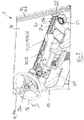
- FIG. 1 is designed as a tractor or platform truck inventive truck 1 shown in a side view.
- the truck 1 has a vehicle frame 2 on which front wheels 3 and rear wheels 4 are arranged. Between the front wheels 3 and the rear wheels 4, a battery compartment 4 is arranged, in which an electric traction battery is arranged.
- the truck 1 is provided in the front, front area with a driver's roof 10, within which a driver's workplace F is designed for an operator of the truck 1.
- the driver's workplace F may include a driver's seat 11 on which the operator sits during operation of the industrial truck 1.
- the truck In the longitudinal direction behind the driver's roof 10, the truck is provided with a loading platform 6, can be transported on the loads.
- the truck In the illustrated embodiment, the truck is provided in the rear, rear-side area with a trailer hitch 7, can be coupled to the trailer.
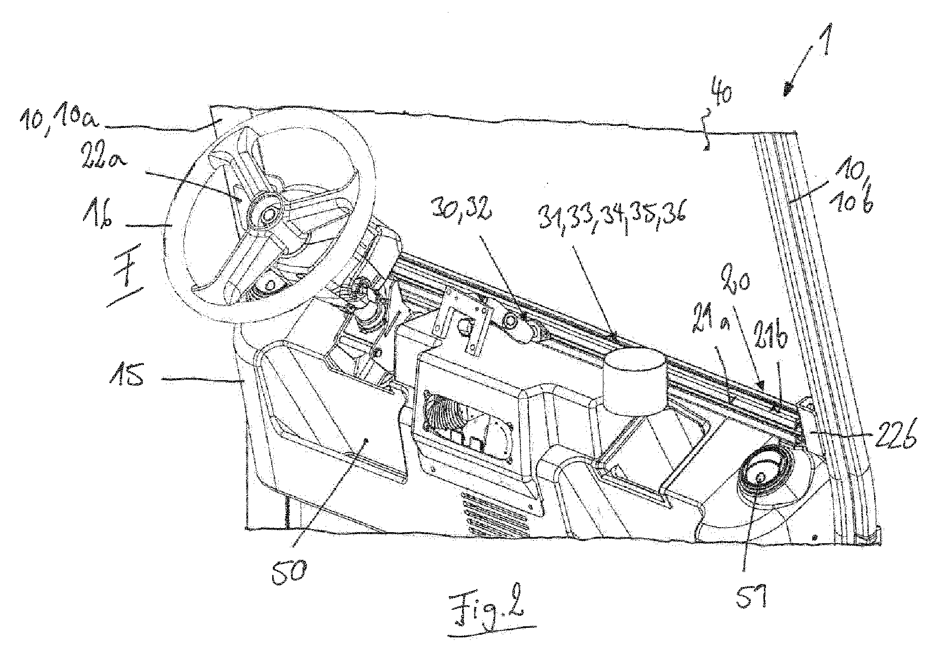
- the driver's protection roof 2 consists of a front left driver protection roof strut 10a, a front right driver protection roof strut 10b and at least one rear driver protection roof strut 10c.
- the driver protection roof struts 10a, 10b, 10c are arranged substantially vertically and connected to each other in the upper roof area of the driver's roof 10 by means of horizontally extending longitudinal struts 10d.
- transverse struts are provided between the left-hand rider struts 10a and the right-hand rider struts 10b.
- a dashboard 15 and a steering wheel 16 is located in the front area of the driver's workplace F within the driver's roof 10.
- a groove profile rail 20 which is provided with at least one groove 21a, 21b.
- the groove profile rail 20 is arranged in the front region of the driver's workplace 10, ie in the area in front of a seated in normal sitting position on the driver's seat 11 operator.
- a component 30 or a plurality of components 30, 31 are fastened by means not shown fastening means, such as nuts, which can be threaded into the groove 21a and the groove 21b.
- the grooves 21a, 21b are each formed as longitudinal grooves which extend in the longitudinal direction of the groove profile rail 20.
- the groove profile rail 20 has a quadrangular cross-section, wherein the groove 21a is disposed on an outer side facing the interior of the driver's roof 10 and the groove 21b on the outside of the groove profile rail 20 forming the upper side.
- the groove profile rail 20 is arranged substantially horizontally over extending in the vehicle transverse direction over the entire width of the driver's roof 10 and the truck 1.
- the groove profile rail 20 is preferably disposed between the front left driver's protection roof strut 10a and the front right driver's protection roof strut 10b.
- the groove profile rail 20 is in the illustrated embodiment of FIGS. 2 to 4 attached to the front left rider strut brace 10a and the front right rider cowl brace 10b.
- the holders 22a, 22b can be fastened to the driver's protection roof struts 10a, 10b by means of a screw connection or a welded connection.
- the groove profile rail 20 is arranged directly above the dashboard 16. It is understood that the groove profile rail 20 can also be arranged in the roof area of the driver's protection roof 10 in the area of the upper ends of the vertical driver protection roof struts 10a, 10b.
- the groove profile rail 20 is thus formed by the attachment to the two driver protection roof struts 10a, 10b as a horizontal, transverse to the vehicle transverse direction of the driver's roof 10.
- the component 30, which is fastened to the groove profile rail 20 by means of a fastening means, for example a sliding block, arranged in the groove 21a, is designed as a holder 32 on which a display or a display and control unit or a terminal or a mobile telephone can be attached.
- the component 31, which is fastened to the groove profile rail 20 by means of a fastening means arranged in the groove 21a, for example a sliding block, is designed as a storage compartment 33 or as a cup holder 34 or as a cup holder 35 or as an ashtray 36 in the illustrated embodiment. It is understood that by means of appropriate fastening means, for example corresponding sliding blocks, which are arranged in the groove 21 a or 21 b, further components can be attached to the groove profile rail 20, for example a reading lamp.
- an interior lining of the driver's workplace F are also fastened to the groove profile rail 20 via corresponding fastening means, for example, sliding blocks arranged in the grooves 21a and 21b.
- a disk 40 for example a windshield, of the driver's protection roof 10 can be fastened to the groove profile rail 20.
- corresponding fastening means arranged in the grooves 21a or 21b for example sliding blocks, or by inserting the disk 40 directly into a groove 21a, 21b.
- groove profile rail 20 may be formed as the only component carrier in the driver's workplace F, on which also arranged on the instrument panel 16 components, such as a storage compartment 50 and nozzles 51 a ventilation and heating device of the driver's workplace F, so that a separate dashboard 16 can be omitted.
- FIGS. 5a to 5c are cross sections of different groove profile rails 20 shown, which can be used in an inventive floor conveyor 1 for fastening components 30, 31.
- the groove profile rails 20 of the FIGS. 5a, 5b have a quadrangular cross section and have on each of the four outer sides in each case a groove 21a, 21b, 21c, 21d, in the fastening means, for example, sliding nuts, for fastening components can be threaded.
- the groove profile rail 20 of FIG. 5c has a substantially triangular cross-section with two straight sides and a rounded side, wherein the two straight sides are each provided with a groove 21a, 21b, can be threaded into the attachment means, such as sliding blocks for mounting components.
- the driver's shelter 10 is formed partially or completely from Nutprofilschienen 20.
- the vertical front driver protection roof struts 10a, 10b, the vertical rear driver protection roof struts 10c, and the horizontally extending longitudinal struts 10d are each formed from groove profile rails 20 with at least one groove 21.
- horizontal cross braces connecting right and left rider struts 10a, 10b may be formed from groove profile rails 20 having at least one groove 21.
- the groove profile rail 20 forms a standardized interface, on which, for example, formed as a sliding blocks fastener, which in the grooves 21 a, 21b, 21c, 21d of the groove profile rail 20 can be threaded, the most diverse components 30, 31 can be grown.
- the respective components 30, 31 may be individually positioned and positioned along the respective groove 21a-21d according to the operator's desire in the driver's seat F.
- the attachment of corresponding components 30, 31 in the grooves 21a-21d of the groove profile rail 20 by means of appropriate fasteners, such as nuts, allows easy attachment and fixation of the corresponding components 30, 31 and an individual adjustability and individual arrangement of the components 30, 31 to the Desire of the operator, so that the groove profile rail 20 of the operator allows an individually designable arrangement of the components 30, 31 in the driver's workplace F.
- the groove profile rail 20 allows an ergonomically favorable arrangement of the components for the respective operator.
- the groove profile rail 20 further allows a high degree of flexibility and a high freedom of design with regard to the arrangement of the components 30, 31.
- the groove profile rail 20 allows a simple implementation of customer requirements.
- the groove profile rail 20 allows easy replacement of defective components 30, 31 as well as easy retrofitting and retrofitting of components 30, 31.
Landscapes
- Engineering & Computer Science (AREA)
- Transportation (AREA)
- Structural Engineering (AREA)
- Mechanical Engineering (AREA)
- Civil Engineering (AREA)
- Life Sciences & Earth Sciences (AREA)
- Geology (AREA)
- Body Structure For Vehicles (AREA)
Abstract
Die Erfindung betrifft ein Flurförderzeug (1) mit einem Fahrerschutzdach (10) und einem innerhalb des Fahrerschutzdaches (10) angeordneten Fahrerarbeitsplatz (F) für eine Bedienperson des Flurförderzeugs (1) und mindestens einer im Fahrerarbeitsplatz (F) angeordneten Komponente (30, 31). Erfindungsgemäß ist im Frontbereich des Fahrerarbeitsplatzes (F) eine Nutprofilschiene (20) angeordnet, die mit zumindest einer Nut (21a; 21b; 21c; 21d) versehen ist, wobei die Komponente (30, 31) mittels eines in die Nut (21a; 21 b; 21c; 21d) eingesetzten Befestigungsmittels, insbesondere eines Nutensteins oder Einrastclips oder Rasthakens, an der Nutprofilschiene (20) befestigt ist.
Description
Die Erfindung betrifft ein Flurförderzeug mit einem Fahrerschutzdach und einem innerhalb des Fahrerschutzdaches angeordneten Fahrerarbeitsplatz für eine Bedienperson des Flurförderzeugs und mindestens einer im Fahrerarbeitsplatz angeordneten Komponente.The invention relates to an industrial truck with a driver's shelter roof and a driver's workplace arranged inside the driver's protection roof for an operator of the industrial truck and at least one component arranged in the driver's workplace.
Bei Flurförderzeugen mit einem innerhalb des Fahrerschutzdaches angeordneten Fahrerarbeitsplatz für eine Bedienperson bildet der Frontbereich des Fahrerarbeitsplatzes ein Armaturenbrett oder ein sogenanntes Cockpit, an dem für die Bedienung des Flurförderzeugs durch die Bedienperson erforderlichen Komponenten angeordnet sind. Bei bekannten Flurförderzeugen ist der Frontbereich des Fahrerarbeitsplatzes derart gestaltet, dass jede Komponente an einem bestimmten und definierten Platz fest angeordnet ist. In der Regel sind die Komponenten in das Armaturenbrett oder eine Cockpitverkleidung integriert. Dadurch können Komponenten nicht oder nur teilweise nachgerüstet werden.In industrial trucks with an arranged inside the driver's roof driver's workplace for an operator, the front of the driver's workplace forms a dashboard or a so-called cockpit, are arranged on the required for the operation of the truck by the operator components. In known industrial trucks, the front area of the driver's workplace is designed such that each component is fixedly arranged at a specific and defined place. In general, the components are integrated into the dashboard or a cockpit panel. As a result, components can not or only partially be retrofitted.
Nachteilig ist hierbei, dass die Bedienperson an die feste Anordnung der Komponenten im Frontbereich des Fahrerarbeitsplatzes gebunden ist und somit an die Struktur gebunden ist, die durch das Armaturenbrett bzw. das Cockpit des Fahrerarbeitsplatzes vorgegeben ist. Die Nachrüstung von weiteren oder zusätzlichen Komponenten ist oft problematisch und aufwändig, da bei bekannten Flurförderzeugen keine definierten Schnittstellen im Fahrerarbeitsplatz vorgesehen sind, an denen Komponenten befestigt und angeordnet werden können. Zudem kann bei bekannten Flurförderzeugen der Fahrerarbeitsplatz nicht individuell an die Wünsche einer Bedienperson hinsichtlich der Anordnung der Komponenten und somit an die Bedienperson angepasst werden. Bei einem integralen Einbau der Komponenten in das Armaturenbrett oder eine Cockpitverkleidung ist zudem nachteilig, dass eine defekte Komponente oft nicht einzeln ausgetauscht werden kann.The disadvantage here is that the operator is bound to the fixed arrangement of the components in the front of the driver's workplace and thus is bound to the structure, which is predetermined by the dashboard and the cockpit of the driver's workplace. The retrofitting of additional or additional components is often problematic and expensive, since in known trucks no defined interfaces are provided in the driver's workplace, where components can be attached and arranged. In addition, in known industrial trucks, the driver's workplace can not be adapted individually to the wishes of an operator with regard to the arrangement of the components and thus to the operator. In an integral installation of the components in the dashboard or a cockpit panel is also disadvantageous that a defective component often can not be replaced individually.
Der vorliegenden Erfindung liegt die Aufgabe zugrunde, ein Flurförderzeug der eingangs genannten Gattung zur Verfügung zu stellen, bei dem die Komponenten individuell an die Wünsche einer Bedienperson im Fahrerarbeitsplatz positioniert werden können, Komponenten einfach nachgerüstet und defekte Komponenten einfach ausgetauscht werden können.The present invention has for its object to provide an industrial truck of the type mentioned in which the components can be individually positioned to the wishes of an operator in the driver's workplace, components can be easily retrofitted and defective components can be easily replaced.
Diese Aufgabe wird erfindungsgemäß dadurch gelöst, dass im Frontbereich des Fahrerarbeitsplatzes eine Nutprofilschiene angeordnet ist, die mit zumindest einer Nut versehen ist, wobei die Komponente mittels eines in die Nut eingesetzten Befestigungsmittels, insbesondere eines Nutensteins oder Einrastclips oder Rasthakens, an der Nutprofilschiene befestigt ist. Erfindungsgemäß ist somit bei dem Flurförderzeug im Frontbereich des Fahrerarbeitsplatzes eine Nutprofilschiene angeordnet, die mit zumindest einer Nut versehen ist. Mit Befestigungsmitteln, insbesondere eines Nutensteins oder eines Einrastclips oder eines Rasthakens, die in die zumindest eine Nut der Nutprofilschiene eingefädelt werden können und in der Nut der Nutprofilschiene hinterschnittig gehalten werden, können an der Nutprofilschiene Komponenten befestigt werden. Eine derartige Nutprofilschiene ermöglicht es, dass entlang der Nut eine Komponente oder mehrere Komponenten beliebig positioniert und befestigt werden können. Die mit der zumindest einen Nut versehen Nutprofilschiene bildet somit eine standardisierte Schnittstelle, an der eine Vielzahl von Komponenten auf einfache Weise befestigt und beliebig positioniert werden können. Die Befestigung von Komponenten in der Nut der Nutprofilschiene mittels entsprechenden Befestigungsmitteln, beispielsweise Nutensteinen, ermöglicht eine einfache Umrüstung und Nachrüstung von Komponenten, eine individuelle an die Wünsche der Bedienperson angepasste Positionierung der Komponenten und somit eine fahrerindividuelle Gestaltung des Fahrerarbeitsplatzes, eine günstige Ergonomie durch eine ergonomisch günstige Anordnung und Anpassung der Komponenten an die jeweilige Bedienperson, einen einfachen Austausch von defekten Komponenten, eine hohe Flexibilität und einen hohen Gestaltungsfreiraum hinsichtlich der Anordnung der Komponenten und eine einfache Umsetzung von Kundenwünschen.This object is achieved in that in the front area of the driver's workplace a Nutprofilschiene is arranged, which is provided with at least one groove, wherein the component is fastened by means of a fastening means inserted into the groove, in particular a sliding block or latching clip or latching hook on the Nutprofilschiene. According to the invention, a groove profile rail is thus arranged in the truck in the front region of the driver's workplace, which is provided with at least one groove. With fastening means, in particular a sliding block or a snap-in clip or a latching hook, which can be threaded into the at least one groove of the groove profile rail and are held undercut in the groove of the groove profile rail, components can be fastened to the groove profile rail. Such a groove profile rail makes it possible for any component or several components to be arbitrarily positioned and fastened along the groove. The groove profile rail provided with the at least one groove thus forms a standardized interface to which a multiplicity of components can be fastened in a simple manner and positioned as desired. The attachment of components in the groove of the groove profile rail by means of appropriate fasteners, such as sliding blocks, allows easy retrofitting and retrofitting of components, an individual adapted to the wishes of the operator positioning of the components and thus a driver-individual design of the driver's workplace, a favorable ergonomics ergonomic favorable arrangement and adaptation of the components to the respective operator, a simple replacement of defective components, a high degree of flexibility and a high degree of design freedom with regard to the arrangement of the components and a simple implementation of customer requirements.
Gemäß einer vorteilhaften Ausgestaltungsform der Erfindung ist die Nutprofilschiene im Wesentlichen horizontal angeordnet und erstreckt sich über die gesamte Breite des Fahrerschutzdaches. Dies ermöglicht es, eine oder mehrere Komponenten über die gesamte Breite des Fahrerschutzdaches im Frontbereich des Fahrerarbeitsplatzes entlang der Nutprofilschiene anzuordnen.According to an advantageous embodiment of the invention, the groove profile rail is arranged substantially horizontally and extends over the entire width of the driver's roof. This makes it possible to arrange one or more components over the entire width of the driver's protection roof in the front area of the driver's workplace along the groove profile rail.
Vorteilhafterweise ist hierbei die Nutprofilschiene zwischen einer linken und einer rechten vertikalen Fahrerschutzdachstrebe angeordnet.Advantageously, in this case the groove profile rail between a left and a right vertical driver protection roof strut is arranged.
Sofern die Nutprofilschiene an der linken und an der rechten vertikalen Fahrerschutzdachstrebe befestigt ist, kann eine einfache Weise eine Befestigung der Nutprofilschiene im Frontbereich des Fahrerarbeitsplatzes erzielt werden. Die Nutprofilschiene ist hierbei bevorzugt an der linken und an der rechten vertikalen Fahrerschutzdachstrebe mittels Schraubverbindungen oder Schweißverbindungen befestigt.If the groove profile rail is fastened to the left and to the right vertical driver protection roof strut, a simple way of fastening the groove profile rail in the front area of the driver's workplace can be achieved. The groove profile rail is in this case preferably attached to the left and to the right vertical driver protection roof strut by means of screw or welded joints.
Die Nutprofilschiene kann gemäß einer vorteilhaften Weiterbildung der Erfindung als Querstrebe des Fahrerschutzdaches und somit als tragende Struktur des Fahrerschutzdaches ausgebildet sein.The groove profile rail can be formed according to an advantageous embodiment of the invention as a cross member of the driver's roof and thus as a supporting structure of the driver's roof.
Gemäß einer vorteilhaften Weiterbildung der Erfindung ist die Nutprofilschiene unmittelbar oberhalb eines Armaturenbretts angeordnet oder als Bestandteil des Armaturenbretts ausgebildet. Sofern die Nutprofilschiene als Bestandteil des Armaturenbretts ausgebildet ist, ergeben sich weitere Vorteile, da die Nutprofilschiene die Funktion des Armaturenbretts zur Befestigung von Komponenten übernehmen kann, so dass kein eigenständiges Armaturenbrett mehr für die Befestigung und Anordnung von Komponenten im Frontbereich des Fahrerarbeitsplatzes mehr erforderlich ist.According to an advantageous embodiment of the invention, the groove profile rail is arranged directly above a dashboard or formed as part of the dashboard. If the groove profile rail is formed as part of the dashboard, there are further advantages, since the groove profile rail can take over the function of the dashboard for attachment of components, so that no separate dashboard more for the attachment and arrangement of components in the front of the driver's workplace is more necessary.
Alternativ oder zusätzlich kann die Nutprofilschiene im Dachbereich des Fahrerschutzdaches angeordnet sein.Alternatively or additionally, the groove profile rail can be arranged in the roof area of the driver's protection roof.
Gemäß einer vorteilhaften Weiterbildung der Erfindung ist das Fahrerschutzdach zumindest teilweise aus Nutprofilschienen gebildet. Dies ermöglicht es, auch an anderen Stellen des Fahrerschutzdaches mit entsprechenden Befestigungsmitteln, beispielsweise Nutensteinen, die in die Nuten der das Fahrerschutzdach bildenden Nutprofilschienen eingefädelt werden können, entsprechende Komponenten einfach und hinsichtlich der Positionierung flexibel zu befestigen.According to an advantageous embodiment of the invention, the driver's protection roof is at least partially formed from Nutprofilschienen. This makes it possible to flexibly secure corresponding components to other parts of the driver's roof with corresponding fastening means, such as sliding blocks, which can be threaded into the grooves of the groove profile rails forming the driver's protection roof, and flexible in terms of positioning.
Besondere Vorteile ergeben sich, wenn gemäß einer Weiterbildung der Erfindung die Nutprofilschiene an zumindest zwei Außenseiten jeweils eine Nut aufweist. Dadurch ergeben sich weitere Vorteile hinsichtlich einer flexiblen und variablen Anordnung der Komponenten entlang der Nuten der Nutprofilschiene. Zudem lassen sich mit mehreren Nuten an der Nutprofilschiene eine hohe Anzahl von Komponenten befestigen und positionieren.Particular advantages arise when, according to an embodiment of the invention, the groove profile rail has at least two outer sides in each case a groove. Thereby There are further advantages in terms of a flexible and variable arrangement of the components along the grooves of the groove profile rail. In addition, a large number of components can be fastened and positioned on the groove profile rail with several grooves.
Die mindestens eine Komponente ist vorteilhafterweise von einem Halter eines Displays oder einem Halter einer Anzeige- und Bedieneinheit oder einem Halter eines Terminals, beispielsweise eines Logistik-Terminals oder eines Warenmanagementsystems, oder einem Mobiltelefonhalter oder einem Werkzeughalter oder einem Ablagefach oder einer Leselampe oder einer Beleuchtungseinrichtung des Flurförderzeugs, beispielsweise einem Blinker oder einem Arbeitsscheinwerfer, oder einem Haltegriff oder einem Becherhalter oder einem Getränkehalter oder einem Aschenbecher oder einem Spiegel, beispielsweise einem Rückspiegel, oder einer Sonnenblende gebildet.The at least one component is advantageously of a holder of a display or a holder of a display and control unit or a holder of a terminal, such as a logistics terminal or a goods management system, or a mobile phone holder or a tool holder or a storage compartment or a reading lamp or a lighting device of Truck, such as a turn signal or a worklight, or a handle or a cup holder or a cup holder or an ashtray or a mirror, such as a rearview mirror, or a sun visor formed.
Gemäß einer vorteilhaften Weiterbildung kann an der Nutprofilschiene eine Innenraumverkleidung des Fahrerarbeitsplatzes befestigt sein, beispielsweise mittels entsprechender Halter, die über in die Nut der Nutprofilschiene eingesetzte Befestigungsmittel, beispielsweise Nutensteine, an der Nutprofilschiene befestigt sind.According to an advantageous refinement, an interior lining of the driver's workplace can be fastened to the groove profile rail, for example by means of corresponding holders which are fastened to the groove profile rail via fastening means, for example sliding blocks, inserted into the groove of the groove profile rail.
Sofern das Fahrerschutzdach mit einer Scheibe versehen ist, beispielsweise einer Frontscheibe, ergeben sich weitere Vorteile, wenn gemäß einer vorteilhaften Weiterbildung der Erfindung an der Nutprofilschiene die Scheibe des Fahrerschutzdaches befestigt ist, beispielsweise mittels entsprechender Halter, die über in die Nut der Nutprofilschiene eingesetzte Befestigungsmittel, beispielsweise Nutensteine, an der Nutprofilschiene befestigt sind.If the driver's protection roof is provided with a pane, for example a windshield, further advantages result if, according to an advantageous embodiment of the invention, the pane of the driver's shelter roof is secured to the groove profile rail, for example by means of corresponding holders which are fastened via fastening means inserted into the groove of the groove profile rail, For example, sliding blocks are attached to the groove profile rail.
Das Flurförderzeug ist vorteilhafterweise als Gegengewichtsgabelstapler oder als Schlepper oder als Plattformwagen ausgebildet.The truck is advantageously designed as a counterbalance forklift or as a tractor or as a platform truck.
Weitere Vorteile und Einzelheiten der Erfindung werden anhand der in den schematischen Figuren dargestellten Ausführungsbeispiele näher erläutert. Hierbei zeigt
Figur 1- ein erfindungsgemäßes als Schlepper oder Plattformwagen ausgebildetes Flurförderzeug in einer Seitenansicht,
- Figur 2
- einen Ausschnitt des Frontbereichs des Fahrerarbeitsplatzes der
Figur 1 Figur 3- einen Ausschnitt der
Figur 3 Figur 4- die
Figur 2 in einer Ansicht von oben, - Figuren 5a bis 5c
- verschiedene Ausführungsformen einer erfindungsgemäßen Nutprofilschiene und
Figur 6- eine Weiterbildung eines erfindungsgemäßen Flurförderzeugs.
- FIG. 1
- an inventive trained as a tractor or platform truck truck in a side view,
- FIG. 2
- a section of the front area of the driver's workplace of
FIG. 1 in a perspective view, - FIG. 3
- a section of the
FIG. 3 in an enlarged view, - FIG. 4
- the
FIG. 2 in a view from above, - FIGS. 5a to 5c
- various embodiments of a groove profile rail according to the invention and
- FIG. 6
- a development of a truck according to the invention.
In der
Das Flurförderzeug 1 weist einen Fahrzeugrahmen 2 auf, an dem Vorderräder 3 und Hinterräder 4 angeordnet sind. Zwischen den Vorderrädern 3 und den Hinterrädern 4 ist ein Batteriefach 4 angeordnet, in dem eine elektrische Traktionsbatterie angeordnet ist.The
Das Flurförderzeug 1 ist im vorderen, frontseitigen Bereich mit einem Fahrerschutzdach 10 versehen, innerhalb dem ein Fahrerarbeitsplatz F für eine Bedienperson des Flurförderzeugs 1 ausgebildet ist. Der Fahrerarbeitsplatz F kann einen Fahrersitz 11 umfassen, auf dem die Bedienperson während des Betriebs des Flurförderzeugs 1 sitzt.The
In Längsrichtung hinter dem Fahrerschutzdach 10 ist das Flurförderzeug mit einer Ladeplattform 6 versehen, auf der Lasten transportiert werden können. Im dargestellten Ausführungsbeispiel ist das Flurförderzeug im hinteren, heckseitigen Bereich mit einer Anhängekupplung 7 versehen, an die Anhänger angekuppelt werden können.In the longitudinal direction behind the driver's
Das Fahrerschutzdach 2 besteht aus einer vorderen linken Fahrerschutzdachstrebe 10a, einer vorderen rechten Fahrerschutzdachstrebe 10b und zumindest einer hinteren Fahrerschutzdachstrebe 10c. Die Fahrerschutzdachstreben 10a, 10b, 10c sind im Wesentlichen vertikal angeordnet und im oberen Dachbereich des Fahrerschutzdaches 10 mittels horizontal verlaufender Längsstreben 10d miteinander verbunden. Zusätzlich sind Querstreben zwischen der linken Fahrerschutzdachstreben 10a und der rechten Fahrerschutzdachstreben 10b vorgesehen.The driver's protection roof 2 consists of a front left driver protection roof strut 10a, a front right driver protection roof strut 10b and at least one rear driver
Wie in den
Erfindungsgemäß ist - wie in den
In dem Ausführungsbeispiel der
Im Ausführungsbeispiel der
Im Ausführungsbeispiel der
Die Komponente 30, die mittels eines in der Nut 21a angeordneten Befestigungsmittels, beispielsweise eines Nutensteins, an der Nutprofilschiene 20 befestigt ist, ist im dargestellten Ausführungsbeispiel als Halter 32 ausgebildet, an dem ein Display oder eine Anzeige- und Bedieneinheit oder ein Terminal oder ein Mobiltelefon befestigt werden kann. Die Komponente 31, die mittels eines in der Nut 21a angeordneten Befestigungsmittels, beispielsweise eines Nutensteins, an der Nutprofilschiene 20 befestigt ist, ist im dargestellten Ausführungsbeispiel als Ablagefach 33 oder als Becherhalter 34 oder als Getränkehalter 35 oder als Aschenbecher 36 ausgebildet. Es versteht sich, dass mittels entsprechender Befestigungsmittel, beispielsweise entsprechender Nutensteine, die in der Nut 21 a oder 21b angeordnet sind, weitere Komponenten an der Nutprofilschiene 20 befestigt werden können, beispielsweise eine Leselampe.The component 30, which is fastened to the
Es versteht sich, dass an der Nutprofilschiene 20 auch über entsprechende in die Nuten 21a bzw. 21b angeordnete Befestigungsmittel, beispielsweise Nutensteine, eine Innenraumverkleidung des Fahrerarbeitsplatzes F befestigt werden.It is understood that an interior lining of the driver's workplace F are also fastened to the
Zudem kann an der Nutprofilschiene 20 eine Scheibe 40, beispielsweise eine Frontscheibe, des Fahrerschutzdaches 10 befestigt werden. Beispielsweise über entsprechende in die Nuten 21a bzw. 21b angeordnete Befestigungsmittel, beispielsweise Nutensteine, oder indem die Scheibe 40 direkt in eine Nut 21a, 21b hinein gesteckt wird.In addition, a
Es versteht sich weiterhin, dass die Nutprofilschiene 20 als einziger Komponententräger im Fahrerarbeitsplatz F ausgebildet sein kann, an dem auch die am Armaturenbrett 16 angeordneten Komponenten, beispielsweise ein Ablagefach 50 und Düsen 51 einer Lüftungs- und Heizungseinrichtung des Fahrerarbeitsplatzes F, befestigt werden können, so dass ein eigenes Armaturenbrett 16 entfallen kann.It is further understood that the
In den
In der
Die Nutprofilschiene 20 bildet eine standardisierte Schnittstelle, an der über beispielsweise als Nutensteine ausgebildete Befestigungsmittel, die in die Nuten 21a, 21b, 21c, 21d der Nutprofilschiene 20 eingefädelt werden können, die unterschiedlichsten Komponenten 30, 31 angebaut werden können. Die entsprechenden Komponenten 30, 31 können entlang der jeweiligen Nut 21a-21d individuell entsprechend des Wunsches der Bedienperson im Fahrerarbeitsplatz F angeordnet und positioniert werden.The
Die Befestigung von entsprechenden Komponenten 30, 31 in den Nuten 21a-21d der Nutprofilschiene 20 mittels entsprechenden Befestigungsmitteln, beispielsweise Nutensteinen, ermöglicht eine einfache Befestigung und Fixierung der entsprechenden Komponenten 30, 31 sowie eine individuelle Einstellbarkeit und individuelle Anordnung der Komponenten 30, 31 an den Wunsch der Bedienperson, so dass die Nutprofilschiene 20 der Bedienperson eine individuell gestaltbare Anordnung der Komponenten 30, 31 im Fahrerarbeitsplatz F ermöglicht. Zudem ermöglicht die Nutprofilschiene 20 eine ergonomisch günstige Anordnung der Komponenten für die jeweilige Bedienperson. Die Nutprofilschiene 20 ermöglicht weiterhin eine hohe Flexibilität und einen hohen Gestaltungsfreiraum hinsichtlich der Anordnung der Komponenten 30, 31. Zudem ermöglicht die Nutprofilschiene 20 eine einfache Umsetzung von Kundenwünschen. Weiterhin ermöglicht die Nutprofilschiene 20 einen einfachen Austausch von defekten Komponenten 30, 31 sowie eine einfache Umrüstung und Nachrüstung von Komponenten 30, 31.The attachment of corresponding components 30, 31 in the
Claims (13)
Applications Claiming Priority (1)
| Application Number | Priority Date | Filing Date | Title |
|---|---|---|---|
| DE102016123807.4A DE102016123807B4 (en) | 2016-12-08 | 2016-12-08 | Industrial truck with an overhead guard |
Publications (2)
| Publication Number | Publication Date |
|---|---|
| EP3333118A1 true EP3333118A1 (en) | 2018-06-13 |
| EP3333118B1 EP3333118B1 (en) | 2023-01-11 |
Family
ID=60421617
Family Applications (1)
| Application Number | Title | Priority Date | Filing Date |
|---|---|---|---|
| EP17202664.3A Active EP3333118B1 (en) | 2016-12-08 | 2017-11-21 | Industrial truck with a driver protection roof |
Country Status (2)
| Country | Link |
|---|---|
| EP (1) | EP3333118B1 (en) |
| DE (1) | DE102016123807B4 (en) |
Citations (5)
| Publication number | Priority date | Publication date | Assignee | Title |
|---|---|---|---|---|
| DE102010048096A1 (en) * | 2010-10-09 | 2011-06-01 | Daimler Ag | Fixing system for variable and detachable fixing of e.g. notebook in cockpit area of lorry, has holding device including electrical connecting device that provides electrical connection for accessory device arranged in holding device |
| DE102011016840A1 (en) * | 2011-03-30 | 2012-10-04 | Kion Warehouse Systems Gmbh | Industrial truck, particularly industrial pickup truck, has liftable and lowerable operator compartment and operator facility, particularly operator console, where operator facility is arranged on parapet wall |
| DE102011018802A1 (en) * | 2011-04-27 | 2012-10-31 | Still Gmbh | Industrial truck, particularly counterbalance forklift truck, for lifting or lowering of bulky or heavy goods for loading or unloading purposes, has multiple display devices for displaying of vehicle conditions or operating conditions |
| DE102015105689A1 (en) * | 2015-04-14 | 2016-10-20 | Linde Material Handling Gmbh | Fastening device for fastening at least one electrical or electronic attachment to a vehicle body of a mobile work machine |
| DE202016005501U1 (en) * | 2015-09-11 | 2016-11-21 | Hyster-Yale Group, Inc. | Accessory arm for a forklift |
-
2016
- 2016-12-08 DE DE102016123807.4A patent/DE102016123807B4/en active Active
-
2017
- 2017-11-21 EP EP17202664.3A patent/EP3333118B1/en active Active
Patent Citations (5)
| Publication number | Priority date | Publication date | Assignee | Title |
|---|---|---|---|---|
| DE102010048096A1 (en) * | 2010-10-09 | 2011-06-01 | Daimler Ag | Fixing system for variable and detachable fixing of e.g. notebook in cockpit area of lorry, has holding device including electrical connecting device that provides electrical connection for accessory device arranged in holding device |
| DE102011016840A1 (en) * | 2011-03-30 | 2012-10-04 | Kion Warehouse Systems Gmbh | Industrial truck, particularly industrial pickup truck, has liftable and lowerable operator compartment and operator facility, particularly operator console, where operator facility is arranged on parapet wall |
| DE102011018802A1 (en) * | 2011-04-27 | 2012-10-31 | Still Gmbh | Industrial truck, particularly counterbalance forklift truck, for lifting or lowering of bulky or heavy goods for loading or unloading purposes, has multiple display devices for displaying of vehicle conditions or operating conditions |
| DE102015105689A1 (en) * | 2015-04-14 | 2016-10-20 | Linde Material Handling Gmbh | Fastening device for fastening at least one electrical or electronic attachment to a vehicle body of a mobile work machine |
| DE202016005501U1 (en) * | 2015-09-11 | 2016-11-21 | Hyster-Yale Group, Inc. | Accessory arm for a forklift |
Also Published As
| Publication number | Publication date |
|---|---|
| EP3333118B1 (en) | 2023-01-11 |
| DE102016123807B4 (en) | 2025-03-20 |
| DE102016123807A1 (en) | 2018-06-14 |
Similar Documents
| Publication | Publication Date | Title |
|---|---|---|
| DE10062686B4 (en) | Air conditioning system for a vehicle, in particular for a bus | |
| EP1829747A2 (en) | Movable boot area for automotive vehicle, in particular for a passenger vehicle | |
| DE102011052250A1 (en) | Cockpit carrying structure of a motor vehicle | |
| EP1880926B1 (en) | Motor vehicle with a cockpit module | |
| DE10152242A1 (en) | Modular dashboard holding unit, in particular suitable for use in vehicle with single airbag like van or lorry | |
| DE102017119136A1 (en) | inner element | |
| DE102009005942B4 (en) | Mounting arrangement for a wiper system | |
| DE9017550U1 (en) | Collision protection for trucks, especially semi-trailers of articulated lorries | |
| EP3333118B1 (en) | Industrial truck with a driver protection roof | |
| DE102019129401B4 (en) | Bicycle rack attachment device, motor vehicle and motor vehicle trailer | |
| DE10315635A1 (en) | Vehicle roof for passenger car, has fixing devices at front and rear of roof structure for attachment of central console to underside of the roof | |
| DE10215971A1 (en) | Roof-mounted load carrier for motor vehicles consists of carrier elements sliding in guide units to extend telescopically outwards over rear roof edge, for suspended mounting of bicycles | |
| EP2900535B1 (en) | Bracket for connecting roof-mounted structures of a rail vehicle to the rail vehicle | |
| EP3333119A9 (en) | Industrial truck with a driver protection roof | |
| DE102008012647A1 (en) | Cockpit cross-member for passenger vehicle body, comprises multiple individual modules, where steering console is provided as individual module, and support elements are laterally connected on steering console | |
| EP2177424B1 (en) | Cross-member for a motor vehicle | |
| DE10105168A1 (en) | vehicle roof | |
| DE19855621B4 (en) | Body structure for a passenger car | |
| DE102006058105B4 (en) | Cockpit assembly and motor vehicle | |
| EP2957484A2 (en) | Mudguard for a vehicle, preferably commercial vehicle | |
| DE102019007572A1 (en) | Cladding of a roof structure of a driver's cab of a commercial vehicle | |
| DE102007039859B4 (en) | Cover arrangement and motor vehicle | |
| EP4613563A1 (en) | Commercial vehicle with an engine cover for reducing engine noise | |
| DE102024100695A1 (en) | Technology for producing a configurable operating area of an instrument panel of a motor vehicle | |
| DE102016010751A1 (en) | Connection module for attaching a hardtop to a motor vehicle, use and method for using such a connection module and with such a connection module equipped motor vehicle |
Legal Events
| Date | Code | Title | Description |
|---|---|---|---|
| PUAI | Public reference made under article 153(3) epc to a published international application that has entered the european phase |
Free format text: ORIGINAL CODE: 0009012 |
|
| STAA | Information on the status of an ep patent application or granted ep patent |
Free format text: STATUS: THE APPLICATION HAS BEEN PUBLISHED |
|
| AK | Designated contracting states |
Kind code of ref document: A1 Designated state(s): AL AT BE BG CH CY CZ DE DK EE ES FI FR GB GR HR HU IE IS IT LI LT LU LV MC MK MT NL NO PL PT RO RS SE SI SK SM TR |
|
| AX | Request for extension of the european patent |
Extension state: BA ME |
|
| STAA | Information on the status of an ep patent application or granted ep patent |
Free format text: STATUS: REQUEST FOR EXAMINATION WAS MADE |
|
| 17P | Request for examination filed |
Effective date: 20181204 |
|
| RBV | Designated contracting states (corrected) |
Designated state(s): AL AT BE BG CH CY CZ DE DK EE ES FI FR GB GR HR HU IE IS IT LI LT LU LV MC MK MT NL NO PL PT RO RS SE SI SK SM TR |
|
| RIC1 | Information provided on ipc code assigned before grant |
Ipc: B60R 11/00 20060101ALN20220823BHEP Ipc: B60R 11/02 20060101ALI20220823BHEP Ipc: B66F 9/075 20060101AFI20220823BHEP |
|
| GRAP | Despatch of communication of intention to grant a patent |
Free format text: ORIGINAL CODE: EPIDOSNIGR1 |
|
| STAA | Information on the status of an ep patent application or granted ep patent |
Free format text: STATUS: GRANT OF PATENT IS INTENDED |
|
| INTG | Intention to grant announced |
Effective date: 20221027 |
|
| RIC1 | Information provided on ipc code assigned before grant |
Ipc: B60R 11/00 20060101ALN20221017BHEP Ipc: B60R 11/02 20060101ALI20221017BHEP Ipc: B66F 9/075 20060101AFI20221017BHEP |
|
| GRAS | Grant fee paid |
Free format text: ORIGINAL CODE: EPIDOSNIGR3 |
|
| GRAA | (expected) grant |
Free format text: ORIGINAL CODE: 0009210 |
|
| STAA | Information on the status of an ep patent application or granted ep patent |
Free format text: STATUS: THE PATENT HAS BEEN GRANTED |
|
| AK | Designated contracting states |
Kind code of ref document: B1 Designated state(s): AL AT BE BG CH CY CZ DE DK EE ES FI FR GB GR HR HU IE IS IT LI LT LU LV MC MK MT NL NO PL PT RO RS SE SI SK SM TR |
|
| REG | Reference to a national code |
Ref country code: GB Ref legal event code: FG4D Free format text: NOT ENGLISH |
|
| REG | Reference to a national code |
Ref country code: CH Ref legal event code: EP |
|
| REG | Reference to a national code |
Ref country code: DE Ref legal event code: R096 Ref document number: 502017014315 Country of ref document: DE |
|
| REG | Reference to a national code |
Ref country code: IE Ref legal event code: FG4D Free format text: LANGUAGE OF EP DOCUMENT: GERMAN |
|
| REG | Reference to a national code |
Ref country code: AT Ref legal event code: REF Ref document number: 1543340 Country of ref document: AT Kind code of ref document: T Effective date: 20230215 |
|
| REG | Reference to a national code |
Ref country code: LT Ref legal event code: MG9D |
|
| REG | Reference to a national code |
Ref country code: NL Ref legal event code: MP Effective date: 20230111 |
|
| P01 | Opt-out of the competence of the unified patent court (upc) registered |
Effective date: 20230518 |
|
| PG25 | Lapsed in a contracting state [announced via postgrant information from national office to epo] |
Ref country code: NL Free format text: LAPSE BECAUSE OF FAILURE TO SUBMIT A TRANSLATION OF THE DESCRIPTION OR TO PAY THE FEE WITHIN THE PRESCRIBED TIME-LIMIT Effective date: 20230111 |
|
| PG25 | Lapsed in a contracting state [announced via postgrant information from national office to epo] |
Ref country code: RS Free format text: LAPSE BECAUSE OF FAILURE TO SUBMIT A TRANSLATION OF THE DESCRIPTION OR TO PAY THE FEE WITHIN THE PRESCRIBED TIME-LIMIT Effective date: 20230111 Ref country code: PT Free format text: LAPSE BECAUSE OF FAILURE TO SUBMIT A TRANSLATION OF THE DESCRIPTION OR TO PAY THE FEE WITHIN THE PRESCRIBED TIME-LIMIT Effective date: 20230511 Ref country code: NO Free format text: LAPSE BECAUSE OF FAILURE TO SUBMIT A TRANSLATION OF THE DESCRIPTION OR TO PAY THE FEE WITHIN THE PRESCRIBED TIME-LIMIT Effective date: 20230411 Ref country code: LV Free format text: LAPSE BECAUSE OF FAILURE TO SUBMIT A TRANSLATION OF THE DESCRIPTION OR TO PAY THE FEE WITHIN THE PRESCRIBED TIME-LIMIT Effective date: 20230111 Ref country code: LT Free format text: LAPSE BECAUSE OF FAILURE TO SUBMIT A TRANSLATION OF THE DESCRIPTION OR TO PAY THE FEE WITHIN THE PRESCRIBED TIME-LIMIT Effective date: 20230111 Ref country code: HR Free format text: LAPSE BECAUSE OF FAILURE TO SUBMIT A TRANSLATION OF THE DESCRIPTION OR TO PAY THE FEE WITHIN THE PRESCRIBED TIME-LIMIT Effective date: 20230111 Ref country code: ES Free format text: LAPSE BECAUSE OF FAILURE TO SUBMIT A TRANSLATION OF THE DESCRIPTION OR TO PAY THE FEE WITHIN THE PRESCRIBED TIME-LIMIT Effective date: 20230111 |
|
| PG25 | Lapsed in a contracting state [announced via postgrant information from national office to epo] |
Ref country code: SE Free format text: LAPSE BECAUSE OF FAILURE TO SUBMIT A TRANSLATION OF THE DESCRIPTION OR TO PAY THE FEE WITHIN THE PRESCRIBED TIME-LIMIT Effective date: 20230111 Ref country code: PL Free format text: LAPSE BECAUSE OF FAILURE TO SUBMIT A TRANSLATION OF THE DESCRIPTION OR TO PAY THE FEE WITHIN THE PRESCRIBED TIME-LIMIT Effective date: 20230111 Ref country code: IS Free format text: LAPSE BECAUSE OF FAILURE TO SUBMIT A TRANSLATION OF THE DESCRIPTION OR TO PAY THE FEE WITHIN THE PRESCRIBED TIME-LIMIT Effective date: 20230511 Ref country code: GR Free format text: LAPSE BECAUSE OF FAILURE TO SUBMIT A TRANSLATION OF THE DESCRIPTION OR TO PAY THE FEE WITHIN THE PRESCRIBED TIME-LIMIT Effective date: 20230412 Ref country code: FI Free format text: LAPSE BECAUSE OF FAILURE TO SUBMIT A TRANSLATION OF THE DESCRIPTION OR TO PAY THE FEE WITHIN THE PRESCRIBED TIME-LIMIT Effective date: 20230111 |
|
| REG | Reference to a national code |
Ref country code: DE Ref legal event code: R097 Ref document number: 502017014315 Country of ref document: DE |
|
| PG25 | Lapsed in a contracting state [announced via postgrant information from national office to epo] |
Ref country code: SM Free format text: LAPSE BECAUSE OF FAILURE TO SUBMIT A TRANSLATION OF THE DESCRIPTION OR TO PAY THE FEE WITHIN THE PRESCRIBED TIME-LIMIT Effective date: 20230111 Ref country code: RO Free format text: LAPSE BECAUSE OF FAILURE TO SUBMIT A TRANSLATION OF THE DESCRIPTION OR TO PAY THE FEE WITHIN THE PRESCRIBED TIME-LIMIT Effective date: 20230111 Ref country code: EE Free format text: LAPSE BECAUSE OF FAILURE TO SUBMIT A TRANSLATION OF THE DESCRIPTION OR TO PAY THE FEE WITHIN THE PRESCRIBED TIME-LIMIT Effective date: 20230111 Ref country code: DK Free format text: LAPSE BECAUSE OF FAILURE TO SUBMIT A TRANSLATION OF THE DESCRIPTION OR TO PAY THE FEE WITHIN THE PRESCRIBED TIME-LIMIT Effective date: 20230111 Ref country code: CZ Free format text: LAPSE BECAUSE OF FAILURE TO SUBMIT A TRANSLATION OF THE DESCRIPTION OR TO PAY THE FEE WITHIN THE PRESCRIBED TIME-LIMIT Effective date: 20230111 |
|
| PLBE | No opposition filed within time limit |
Free format text: ORIGINAL CODE: 0009261 |
|
| STAA | Information on the status of an ep patent application or granted ep patent |
Free format text: STATUS: NO OPPOSITION FILED WITHIN TIME LIMIT |
|
| PG25 | Lapsed in a contracting state [announced via postgrant information from national office to epo] |
Ref country code: SK Free format text: LAPSE BECAUSE OF FAILURE TO SUBMIT A TRANSLATION OF THE DESCRIPTION OR TO PAY THE FEE WITHIN THE PRESCRIBED TIME-LIMIT Effective date: 20230111 |
|
| 26N | No opposition filed |
Effective date: 20231012 |
|
| PG25 | Lapsed in a contracting state [announced via postgrant information from national office to epo] |
Ref country code: SI Free format text: LAPSE BECAUSE OF FAILURE TO SUBMIT A TRANSLATION OF THE DESCRIPTION OR TO PAY THE FEE WITHIN THE PRESCRIBED TIME-LIMIT Effective date: 20230111 |
|
| PG25 | Lapsed in a contracting state [announced via postgrant information from national office to epo] |
Ref country code: IT Free format text: LAPSE BECAUSE OF FAILURE TO SUBMIT A TRANSLATION OF THE DESCRIPTION OR TO PAY THE FEE WITHIN THE PRESCRIBED TIME-LIMIT Effective date: 20230111 |
|
| REG | Reference to a national code |
Ref country code: CH Ref legal event code: PL |
|
| PG25 | Lapsed in a contracting state [announced via postgrant information from national office to epo] |
Ref country code: MC Free format text: LAPSE BECAUSE OF FAILURE TO SUBMIT A TRANSLATION OF THE DESCRIPTION OR TO PAY THE FEE WITHIN THE PRESCRIBED TIME-LIMIT Effective date: 20230111 |
|
| PG25 | Lapsed in a contracting state [announced via postgrant information from national office to epo] |
Ref country code: LU Free format text: LAPSE BECAUSE OF NON-PAYMENT OF DUE FEES Effective date: 20231121 |
|
| PG25 | Lapsed in a contracting state [announced via postgrant information from national office to epo] |
Ref country code: CH Free format text: LAPSE BECAUSE OF NON-PAYMENT OF DUE FEES Effective date: 20231130 |
|
| GBPC | Gb: european patent ceased through non-payment of renewal fee |
Effective date: 20231121 |
|
| PG25 | Lapsed in a contracting state [announced via postgrant information from national office to epo] |
Ref country code: MC Free format text: LAPSE BECAUSE OF FAILURE TO SUBMIT A TRANSLATION OF THE DESCRIPTION OR TO PAY THE FEE WITHIN THE PRESCRIBED TIME-LIMIT Effective date: 20230111 Ref country code: LU Free format text: LAPSE BECAUSE OF NON-PAYMENT OF DUE FEES Effective date: 20231121 Ref country code: CH Free format text: LAPSE BECAUSE OF NON-PAYMENT OF DUE FEES Effective date: 20231130 |
|
| REG | Reference to a national code |
Ref country code: BE Ref legal event code: MM Effective date: 20231130 |
|
| REG | Reference to a national code |
Ref country code: IE Ref legal event code: MM4A |
|
| PG25 | Lapsed in a contracting state [announced via postgrant information from national office to epo] |
Ref country code: IE Free format text: LAPSE BECAUSE OF NON-PAYMENT OF DUE FEES Effective date: 20231121 |
|
| PG25 | Lapsed in a contracting state [announced via postgrant information from national office to epo] |
Ref country code: GB Free format text: LAPSE BECAUSE OF NON-PAYMENT OF DUE FEES Effective date: 20231121 |
|
| PG25 | Lapsed in a contracting state [announced via postgrant information from national office to epo] |
Ref country code: BE Free format text: LAPSE BECAUSE OF NON-PAYMENT OF DUE FEES Effective date: 20231130 |
|
| PG25 | Lapsed in a contracting state [announced via postgrant information from national office to epo] |
Ref country code: IE Free format text: LAPSE BECAUSE OF NON-PAYMENT OF DUE FEES Effective date: 20231121 Ref country code: GB Free format text: LAPSE BECAUSE OF NON-PAYMENT OF DUE FEES Effective date: 20231121 Ref country code: BE Free format text: LAPSE BECAUSE OF NON-PAYMENT OF DUE FEES Effective date: 20231130 |
|
| PG25 | Lapsed in a contracting state [announced via postgrant information from national office to epo] |
Ref country code: BG Free format text: LAPSE BECAUSE OF FAILURE TO SUBMIT A TRANSLATION OF THE DESCRIPTION OR TO PAY THE FEE WITHIN THE PRESCRIBED TIME-LIMIT Effective date: 20230111 |
|
| PG25 | Lapsed in a contracting state [announced via postgrant information from national office to epo] |
Ref country code: BG Free format text: LAPSE BECAUSE OF FAILURE TO SUBMIT A TRANSLATION OF THE DESCRIPTION OR TO PAY THE FEE WITHIN THE PRESCRIBED TIME-LIMIT Effective date: 20230111 |
|
| REG | Reference to a national code |
Ref country code: AT Ref legal event code: MM01 Ref document number: 1543340 Country of ref document: AT Kind code of ref document: T Effective date: 20231121 |
|
| PG25 | Lapsed in a contracting state [announced via postgrant information from national office to epo] |
Ref country code: AT Free format text: LAPSE BECAUSE OF NON-PAYMENT OF DUE FEES Effective date: 20231121 |
|
| PG25 | Lapsed in a contracting state [announced via postgrant information from national office to epo] |
Ref country code: AT Free format text: LAPSE BECAUSE OF NON-PAYMENT OF DUE FEES Effective date: 20231121 |
|
| PG25 | Lapsed in a contracting state [announced via postgrant information from national office to epo] |
Ref country code: CY Free format text: LAPSE BECAUSE OF FAILURE TO SUBMIT A TRANSLATION OF THE DESCRIPTION OR TO PAY THE FEE WITHIN THE PRESCRIBED TIME-LIMIT; INVALID AB INITIO Effective date: 20171121 |
|
| PG25 | Lapsed in a contracting state [announced via postgrant information from national office to epo] |
Ref country code: HU Free format text: LAPSE BECAUSE OF FAILURE TO SUBMIT A TRANSLATION OF THE DESCRIPTION OR TO PAY THE FEE WITHIN THE PRESCRIBED TIME-LIMIT; INVALID AB INITIO Effective date: 20171121 |
|
| PG25 | Lapsed in a contracting state [announced via postgrant information from national office to epo] |
Ref country code: TR Free format text: LAPSE BECAUSE OF FAILURE TO SUBMIT A TRANSLATION OF THE DESCRIPTION OR TO PAY THE FEE WITHIN THE PRESCRIBED TIME-LIMIT Effective date: 20230111 |
|
| PGFP | Annual fee paid to national office [announced via postgrant information from national office to epo] |
Ref country code: DE Payment date: 20251118 Year of fee payment: 9 |
|
| PGFP | Annual fee paid to national office [announced via postgrant information from national office to epo] |
Ref country code: FR Payment date: 20251120 Year of fee payment: 9 |