EP3312133A1 - Drinking water dispensing apparatus capable of producing carbonated water - Google Patents
Drinking water dispensing apparatus capable of producing carbonated water Download PDFInfo
- Publication number
- EP3312133A1 EP3312133A1 EP17197221.9A EP17197221A EP3312133A1 EP 3312133 A1 EP3312133 A1 EP 3312133A1 EP 17197221 A EP17197221 A EP 17197221A EP 3312133 A1 EP3312133 A1 EP 3312133A1
- Authority
- EP
- European Patent Office
- Prior art keywords
- water
- dispensing
- carbonator
- pump
- drinking water
- Prior art date
- Legal status (The legal status is an assumption and is not a legal conclusion. Google has not performed a legal analysis and makes no representation as to the accuracy of the status listed.)
- Granted
Links
Images

Classifications
-
- B—PERFORMING OPERATIONS; TRANSPORTING
- B67—OPENING, CLOSING OR CLEANING BOTTLES, JARS OR SIMILAR CONTAINERS; LIQUID HANDLING
- B67D—DISPENSING, DELIVERING OR TRANSFERRING LIQUIDS, NOT OTHERWISE PROVIDED FOR
- B67D1/00—Apparatus or devices for dispensing beverages on draught
- B67D1/0042—Details of specific parts of the dispensers
- B67D1/0057—Carbonators
- B67D1/0058—In-line carbonators
-
- B—PERFORMING OPERATIONS; TRANSPORTING
- B67—OPENING, CLOSING OR CLEANING BOTTLES, JARS OR SIMILAR CONTAINERS; LIQUID HANDLING
- B67D—DISPENSING, DELIVERING OR TRANSFERRING LIQUIDS, NOT OTHERWISE PROVIDED FOR
- B67D1/00—Apparatus or devices for dispensing beverages on draught
- B67D1/0042—Details of specific parts of the dispensers
- B67D1/0057—Carbonators
- B67D1/0061—Carbonators with cooling means
- B67D1/0066—Carbonators with cooling means outside the carbonator
-
- B—PERFORMING OPERATIONS; TRANSPORTING
- B67—OPENING, CLOSING OR CLEANING BOTTLES, JARS OR SIMILAR CONTAINERS; LIQUID HANDLING
- B67D—DISPENSING, DELIVERING OR TRANSFERRING LIQUIDS, NOT OTHERWISE PROVIDED FOR
- B67D1/00—Apparatus or devices for dispensing beverages on draught
- B67D1/0042—Details of specific parts of the dispensers
- B67D1/0057—Carbonators
- B67D1/0069—Details
- B67D1/0074—Automatic carbonation control
- B67D1/0076—Automatic carbonation control by sensing temperature
-
- B—PERFORMING OPERATIONS; TRANSPORTING
- B67—OPENING, CLOSING OR CLEANING BOTTLES, JARS OR SIMILAR CONTAINERS; LIQUID HANDLING
- B67D—DISPENSING, DELIVERING OR TRANSFERRING LIQUIDS, NOT OTHERWISE PROVIDED FOR
- B67D1/00—Apparatus or devices for dispensing beverages on draught
- B67D1/08—Details
- B67D1/12—Flow or pressure control devices or systems, e.g. valves, gas pressure control, level control in storage containers
- B67D1/1256—Anti-dripping devices
-
- B—PERFORMING OPERATIONS; TRANSPORTING
- B67—OPENING, CLOSING OR CLEANING BOTTLES, JARS OR SIMILAR CONTAINERS; LIQUID HANDLING
- B67D—DISPENSING, DELIVERING OR TRANSFERRING LIQUIDS, NOT OTHERWISE PROVIDED FOR
- B67D1/00—Apparatus or devices for dispensing beverages on draught
- B67D1/08—Details
- B67D1/12—Flow or pressure control devices or systems, e.g. valves, gas pressure control, level control in storage containers
- B67D1/14—Reducing valves or control taps
Definitions
- the present invention relates to an apparatus for dispensing drinking water, capable of producing carbonated water.
- Distribution devices of this type are well known and are described in particular in the French patent applications FR2938248 and FR3005044 .
- the carbonator or gasification device of this type of apparatus generally does not operate at a temperature allowing optimum production of carbonated water (ideally 4-5 ° C).
- the water dispensing apparatus of the US patent US9309103 proposes, in this regard, to immerse the carbonator in a refrigeration tank also receiving a coil disposed upstream of the carbonator and for cooling water to room temperature, before passing into the carbonator.
- the present invention generally relates to provisions to avoid these disadvantages and further leading to other advantages.
- the carbonator is in optimal conditions of production of gaseous water in terms of the operating temperature.
- the circulation of water in the cooling circuit before any dispensing of carbonated water at the distribution point makes it possible to evacuate water from the circuit for producing carbonated water at ambient temperature which could have stagnated in the circuit of production of sparkling water since the last drawing. It is thus also avoided to dispense gaseous water heated by ambient temperature while it is usually distributed at temperatures between 5 and 10 ° C.
- the gaseous water production circuit also comprises a flow control compensator disposed between the carbonator and the distribution point. This allows to regulate the output flow of carbonated water by maintaining a pressure in the carbonator, in order to improve the dissolution of the carbon dioxide in the water.
- the compensator is constantly open to the air through the distribution point, thus avoiding a drop by drop due to the residual pressure in the water / carbon dioxide mixture.
- the distribution point is formed by a jet-splitter connected to the compensator to avoid splashing during the distribution of water.
- this jetbreaker comprises two concentric tubes, the inner tube being closed at one end of the water distribution and having axial slots for the passage of water from the inner tube to the cylindrical space extending between the two tubes, this cylindrical space being open at the dispensing end and closed at its end opposite to that of distribution by connecting the inner tube to the outer tube.
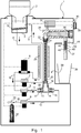
- the fountain 1 shown on the figure 1 is supplied with water by a spilled water canister 2 which feeds a refrigerated water tank 3 at the upper end of the fountain 1.
- the refrigeration of the water of the tank is obtained by means of an evaporator 34 and the tank 3 is removable in order to replace it for hygiene reasons.
- an electronic card 31 printed circuit board
- a pump 6 and a solenoid valve 7 By pressing the button of a selection switch 29 of the fountain 1, an electronic card 31 (printed circuit board) operates for a predetermined period of time, a pump 6 and a solenoid valve 7, to circulate water refrigerated from the tank 3 in a conduit 4 connecting the reservoir 3 to the pump 6, in this pump 6, the solenoid valve 7, then a conduit 5 which returns from the solenoid valve 7 to the tank 3.
- the ducts 4 and 5 form a cooling circuit and are plated, for this purpose, on a tube 20 of a static mixer 21 of a carbonator, to refrigerate it and are isolated, for this purpose, by an insulating sheath 23.
- a light 30 flashes during this predetermined period, during which the static mixer 21 is refrigerated and the water, which during a period of non-use has warmed upstream of the pump 6 in the conduit 4, is replaced by reference in the tank 3.
- This predetermined period of time may be fixed (for example of the order of a few seconds, in this case 5 seconds), or variable, for example depending on a temperature of the water detected in the static mixer 21.
- the indicator light 30 switches to steady light to indicate to the consumer the possibility of using by pressing again the button of the selector switch 29.
- the electronic card 31 will this time operate the pump 6 to make circulating the chilled water from the tank 3 in the conduit 4, a solenoid valve 8 also actuated at that time by the electronic card 31, a conduit 11 connecting the solenoid valve 8 to a carbonated water production chamber 28 of the carbonator 39
- the refrigerated water enters this chamber 28 forming a container for producing carbonated water by a connection 17 fixed to the chamber 28 and a calibrated injector 13 of this chamber 28.
- the pump 6 is regulated by this calibrated injector 13 to regulate the pressure and the flow of chilled water entering the static mixer 21, thus avoiding having to adjust the flow of water, thus facilitating the start-up of the apparatus.
- a solenoid valve 9 is also engaged to send carbon dioxide from a bottle 32 to the gaseous water production chamber 28 via an expander 33, a conduit 10 connecting this expander 33 to the solenoid valve 9, this solenoid valve 9, a duct 12 connecting this solenoid valve 9 to the gaseous water production chamber 28 via a fitting 15 fixed to this chamber 28 and a calibrated injector 14.
- This calibrated injector 14 allows to regulate the flow of carbon dioxide entering the gaseous water production chamber 28, the carbon dioxide pressure being here predetermined and not adjustable in order to facilitate the start-up of the apparatus.
- the refrigerated water and carbon dioxide mixture produced in the gaseous water production chamber 28 then passes through an outlet connection 19 of this chamber 28 into the tube 20 of the static mixer 21 and then through a connection 22 of the compensator 24, in this case. latest.
- this compensator is an adjustable cone 25 and its sealing is provided by an O-ring 26.
- a jetbreaker 27 is connected to the outlet of the compensator 24 to distribute the water to a cup 28.
- This static mixer comprises here a series of baffles arranged around the central axis of the tube 20.
- these baffles can be replaced by a single baffle or one or more fins.
- the compensator 24 which is placed at the outlet of the static mixer 21 makes it possible to regulate the outlet flow of carbonated water by virtue of the cone 25, while maintaining a pressure in the mixer 21 in order to improve the dissolution of the carbon dioxide in the water.
- the compensator 24 is open to the air (there is no outlet valve), which allows to avoid a phenomenon of drip due to a residual pressure present in the water / carbon dioxide mixture.
- the baffle 27 mounted on the outlet duct of the compensator 24 makes it possible to break the flow of carbon dioxide contained in the static mixer 21 in order to prevent this gas with a little water from causing a jet of high pressure. at the end of the distribution on the water contained in the cup 28, which could generate splashing.
- the inner tube 41 is connected to the outer tube 40 at its end facing the compensator 24 (proximal end) and is closed at its opposite end ( distal end). It comprises axial slots 42 for passing the gaseous water from the inner tube 41 to the cylindrical space extending between the two tubes 40, 41, this cylindrical space 43 being open at the end of dispensing carbonated water and closed at its opposite end (on the side of the compensator 24, because of the connection of the inner tube 41 to the outer tube 40).
- the inner tube 41 is of shorter length than that of the tube 40.
- the production of carbonated water is optimized in terms of the dissolution of carbon dioxide in water, the first glass of carbonated water dispensed is at a good temperature (between 5 and 10 ° C. in practice), and all this in a compact and easy to clean device.
- the present invention can also be used in the context of a fountain connected to a drinking water network.
- the tank 2 is replaced by a connection to the drinking water network being in the form of a tube 38 connected to a valve 36 of water supply network.
- a float 37 equipping this valve is also provided for filling the chilled water tank 3 and a lid 35 closes the tank 3.
- the electronic card 21 here forms the control means and the delay means defined above.
- the gaseous water production circuit defined above is formed by the ducts 4, 10, 11, 12, 16, the pump 6, the solenoid valves 8, 9, the carbonator 39 (formed by the chamber 28 and the mixer 21), the compensator 24 and the jetbreaker 27.
- the cooling circuit can be arranged in a heat exchange situation with the entire carbonator and not only the static mixer 21, as well as the compensator 24.
- the distribution of carbonated water may, instead of being carried out by a prolonged pressing of the button 29, as described above, be carried out by the distribution of a predefined volume by appropriate programming of the card electronic 31.
Landscapes
- Devices For Dispensing Beverages (AREA)
Abstract
Appareil de distribution d'eau gazeuse de boisson comportant : - un réservoir d'eau réfrigérée (3) amovible ; - un circuit de production d'eau gazeuse entre une sortie du réservoir (3) et un point de distribution, comportant une pompe (6) et un carbonateur (39) et disposé en aval de la pompe ; - un circuit de refroidissement (4, 5) s'étendant sur la partie du circuit de production allant du réservoir (3) à la pompe (6), puis de la pompe (6) à un point du circuit de production situé entre la pompe et le carbonateur, et de ce point au réservoir, le circuit de refroidissement étant disposé, sur une partie de sa longueur, en situation d'échange thermique avec une partie au moins du carbonateur, pour le refroidir ; et - des moyens de temporisation (31) pour faire circuler l'eau réfrigérée dans le circuit de refroidissement pendant une durée prédéterminée avant la production d'eau gazeuse.A carbonated beverage water dispensing apparatus comprising: - a refrigerated water tank (3) removable; - A circuit for producing carbonated water between an outlet of the tank (3) and a distribution point, comprising a pump (6) and a carbonator (39) and disposed downstream of the pump; a cooling circuit (4, 5) extending over the part of the production circuit going from the tank (3) to the pump (6), then from the pump (6) to a point of the production circuit situated between the pump and the carbonator, and from this point to the reservoir, the cooling circuit being disposed, over part of its length, in heat exchange with at least a portion of the carbonator, to cool it; and - Delay means (31) for circulating refrigerated water in the cooling circuit for a predetermined time before the production of carbonated water.
Description
La présente invention a trait à un appareil de distribution d'eau de boisson, apte à produire de l'eau gazeuse.The present invention relates to an apparatus for dispensing drinking water, capable of producing carbonated water.
Il s'agit plus particulièrement d'une fontaine de distribution d'eau alimentée par le réseau d'eau potable ou par une bombonne ou une bouteille interchangeable.It is more particularly a water fountain fed by the drinking water network or by an interchangeable bottle or bottle.
Les appareils de distribution de ce type sont bien connus et sont notamment décrits dans les demandes de brevet français
Le carbonateur ou dispositif de gazéification de ce genre d'appareil ne fonctionne généralement pas à une température permettant une production optimale d'eau gazeuse (idéalement 4-5°C).The carbonator or gasification device of this type of apparatus generally does not operate at a temperature allowing optimum production of carbonated water (ideally 4-5 ° C).
L'appareil de distribution d'eau du brevet américain
La mise en oeuvre de telles dispositions se fait au détriment de la compacité de l'appareil de distribution et est difficile, voire impossible, à mettre en oeuvre lorsque l'on utilise, pour des raisons d'hygiène, un réservoir amovible de production d'eau réfrigérée, tel que cela est le cas avec les appareils de distribution des demandes de brevet français précitées.The implementation of such provisions is detrimental to the compactness of the dispensing apparatus and is difficult if not impossible to implement when using, for hygienic reasons, a removable reservoir for the production of water. refrigerated water, as is the case with the dispensing apparatus of the aforementioned French patent applications.
La présente invention a, d'une manière générale, pour objet des dispositions permettant d'éviter ces inconvénients et conduisant en outre à d'autres avantages.The present invention generally relates to provisions to avoid these disadvantages and further leading to other advantages.
De manière plus précise, elle a pour objet un appareil de distribution d'eau de boisson, comportant :
- un réservoir d'eau réfrigérée amovible ;
- un circuit de production d'eau gazeuse, s'étendant entre une sortie du réservoir et un point de distribution de l'eau gazeuse, le circuit comportant une pompe et un carbonateur pour gazéifier de l'eau réfrigérée en provenance du réservoir et disposé en aval de la pompe dans la direction du point de distribution ;
- un circuit de refroidissement s'étendant sur la partie du circuit de production d'eau gazeuse allant du réservoir à la pompe, puis de la pompe à un point du circuit de production situé entre la pompe et le carbonateur, et de ce point au réservoir, le circuit de refroidissement étant disposé, sur une partie de sa longueur, en situation d'échange thermique avec une partie au moins du carbonateur, de manière à le refroidir ; et
- des moyens de temporisation adaptés à faire circuler l'eau réfrigérée dans le circuit de refroidissement pendant une durée prédéterminée avant la production d'eau gazeuse via le circuit de production d'eau gazeuse.
- a removable chilled water tank;
- a gaseous water production circuit, extending between an outlet of the tank and a distribution point of the carbonated water, the circuit comprising a pump and a carbonator for gasifying refrigerated water from the reservoir and disposed in downstream of the pump in the direction of the distribution point;
- a cooling circuit extending over the portion of the gaseous water production circuit from the tank to the pump, and then from the pump to a point in the production circuit located between the pump and the carbonator, and from this point to the reservoir , the cooling circuit being disposed, over part of its length, in heat exchange with at least a portion of the carbonator, so as to cool it; and
- timing means adapted to circulate refrigerated water in the cooling circuit for a predetermined time before the production of gaseous water via the gaseous water production circuit.
Grâce à ces dispositions, le carbonateur se trouve dans des conditions optimales de production d'eau gazeuse sur le plan de la température de fonctionnement. En outre, la mise en circulation d'eau dans le circuit de refroidissement avant toute distribution d'eau gazeuse au point de distribution, permet d'évacuer du circuit de production d'eau gazeuse de l'eau à température ambiante qui aurait pu stagner dans le circuit de production d'eau gazeuse depuis le dernier puisage. On évite ainsi également de distribuer de l'eau gazeuse réchauffée par la température ambiante alors qu'elle est usuellement distribuée à des températures comprises entre 5 et 10°C.Thanks to these provisions, the carbonator is in optimal conditions of production of gaseous water in terms of the operating temperature. In addition, the circulation of water in the cooling circuit before any dispensing of carbonated water at the distribution point makes it possible to evacuate water from the circuit for producing carbonated water at ambient temperature which could have stagnated in the circuit of production of sparkling water since the last drawing. It is thus also avoided to dispense gaseous water heated by ambient temperature while it is usually distributed at temperatures between 5 and 10 ° C.
Suivant une disposition particulière, le circuit de production d'eau gazeuse comporte également un compensateur de régulation de débit, disposé entre le carbonateur et le point de distribution. Celui-ci permet de réguler le débit de sortie d'eau gazeuse en maintenant une pression dans le carbonateur, afin d'améliorer la dissolution du dioxyde de carbone dans l'eau.According to a particular arrangement, the gaseous water production circuit also comprises a flow control compensator disposed between the carbonator and the distribution point. This allows to regulate the output flow of carbonated water by maintaining a pressure in the carbonator, in order to improve the dissolution of the carbon dioxide in the water.
Suivant une autre disposition particulière, le compensateur est constamment ouvert à l'air libre par l'intermédiaire du point de distribution, permettant ainsi d'éviter un goutte à goutte dû à la pression résiduelle dans le mélange eau / dioxyde de carbone.According to another particular arrangement, the compensator is constantly open to the air through the distribution point, thus avoiding a drop by drop due to the residual pressure in the water / carbon dioxide mixture.
Suivant encore une autre disposition particulière, le point de distribution est formé par un brise-jet raccordé au compensateur pour éviter les éclaboussures lors de la distribution d'eau.According to yet another particular provision, the distribution point is formed by a jet-splitter connected to the compensator to avoid splashing during the distribution of water.
Suivant un développement original en soi, ce brise-jet comporte deux tubes concentriques, le tube interne étant fermé à une extrémité de distribution d'eau et comportant des fentes axiales de passage d'eau du tube interne vers l'espace cylindrique s'étendant entre les deux tubes, cet espace cylindrique étant ouvert à l'extrémité de distribution et fermé à son extrémité opposée à celle de distribution par le raccordement du tube interne au tube externe.According to an original development in itself, this jetbreaker comprises two concentric tubes, the inner tube being closed at one end of the water distribution and having axial slots for the passage of water from the inner tube to the cylindrical space extending between the two tubes, this cylindrical space being open at the dispensing end and closed at its end opposite to that of distribution by connecting the inner tube to the outer tube.
Suivant d'autres dispositions particulières, pouvant éventuellement être combinées et choisies notamment pour des raisons de commodité de fabrication, de coût et/ou d'efficacité de fonctionnement :
- le carbonateur comporte une entrée de gaz reliée à une source de dioxyde de carbone via une électrovanne et une entrée d'eau réfrigérée reliée à la pompe via une électrovanne,
- le circuit de refroidissement comporte une électrovanne après son point de raccordement au circuit de production d'eau gazeuse,
- les entrées de dioxyde de carbone et d'eau réfrigérée forment deux extrémités opposées d'une chambre de production d'eau gazeuse en forme de Y ou de té,
- le carbonateur comporte un mélangeur statique raccordé à une sortie de la chambre de production d'eau gazeuse et pourvu d'au moins une ailette ou d'au moins une chicane disposée autour d'un axe central d'un tube,
- les parties du circuit de refroidissement et du carbonateur en situation d'échange thermique sont enveloppés dans une gaine isolante,
- l'appareil comporte un évaporateur entourant le réservoir amovible d'eau réfrigérée, pour la production de cette eau réfrigérée,
- l'appareil comporte des moyens de commande pour actionner les électrovannes, la pompe et comportant les moyens de temporisation,
- le carbonateur comporte des entrées d'eau réfrigérée et de gaz munies d'injecteurs calibrés.
- the carbonator comprises a gas inlet connected to a source of carbon dioxide via a solenoid valve and a refrigerated water inlet connected to the pump via a solenoid valve,
- the cooling circuit comprises a solenoid valve after its point of connection to the circuit for producing carbonated water,
- the entrances of carbon dioxide and chilled water form two opposite ends of a chamber for producing carbonated water in the form of Y or tee,
- the carbonator comprises a static mixer connected to an outlet of the gaseous water production chamber and provided with at least one fin or at least one baffle arranged around a central axis of a tube,
- the parts of the cooling circuit and the carbonator in a heat exchange situation are wrapped in an insulating sheath,
- the apparatus comprises an evaporator surrounding the removable tank of chilled water, for the production of this refrigerated water,
- the apparatus comprises control means for actuating the solenoid valves, the pump and including the delay means,
- the carbonator comprises refrigerated water and gas inlets provided with calibrated injectors.
D'autres caractéristiques et avantages de l'invention ressortiront de la description de modes de réalisation de l'invention qui suivent, faite à titre illustratif et nullement limitatif, en se référant aux dessins schématiques ci-annexés sur lesquels :
- la
figure 1 est une vue schématique d'un appareil de distribution de boisson conforme à un premier mode de réalisation de la présente invention et - la
figure 2 est une vue schématique d'un deuxième mode de réalisation de cette invention.
- the
figure 1 is a schematic view of a beverage dispensing apparatus according to a first embodiment of the present invention and - the
figure 2 is a schematic view of a second embodiment of this invention.
La fontaine 1 représentée sur la
En appuyant sur le bouton d'un contacteur de sélection 29 de la fontaine 1, une carte électronique 31 (carte à circuit imprimé) actionne pendant une période de temps prédéterminée, une pompe 6 et une électrovanne 7, pour faire circuler de l'eau réfrigérée provenant du réservoir 3 dans un conduit 4 reliant ce réservoir 3 à la pompe 6, dans cette pompe 6, l'électrovanne 7, puis un conduit 5 qui retourne depuis l'électrovanne 7 au réservoir 3.By pressing the button of a
Les conduits 4 et 5 forment un circuit de refroidissement et sont plaqués, à cet effet, sur un tube 20 d'un mélangeur statique 21 d'un carbonateur, pour le réfrigérer et sont isolés, pour ce faire, par une gaine isolante 23.The
Un voyant 30 clignote pendant cette période prédéterminée, lors de laquelle le mélangeur statique 21 est réfrigéré et l'eau, qui pendant une période de non-utilisation se serait réchauffée en amont de la pompe 6 dans le conduit 4, est remplacée par renvoi dans le réservoir 3.A
Cette période de temps prédéterminée peut être fixe (par exemple de l'ordre de quelques secondes, ici 5 secondes), ou variable, par exemple fonction d'une température de l'eau détectée au sein du mélangeur statique 21.This predetermined period of time may be fixed (for example of the order of a few seconds, in this
A la fin de cette période programmée, le voyant 30 passe en lumière fixe pour indiquer au consommateur la possibilité de se servir en appuyant à nouveau sur le bouton du contacteur de sélection 29. La carte électronique 31 va cette fois actionner la pompe 6 pour faire circuler l'eau réfrigérée provenant du réservoir 3 dans le conduit 4, une électrovanne 8 également actionnée à ce moment-là par la carte électronique 31, un conduit 11 reliant cette électrovanne 8 à une chambre de production d'eau gazeuse 28 du carbonateur 39. L'eau réfrigérée pénètre dans cette chambre 28 formant un récipient de production d'eau gazeuse par un raccord 17 fixé à la chambre 28 puis un injecteur calibré 13 de cette chambre 28. La pompe 6 est régulée par cet injecteur calibré 13 pour régler la pression et le débit d'eau réfrigérée entrant dans le mélangeur statique 21, évitant ainsi d'avoir à régler le débit d'eau, facilitant ainsi la mise en route de l'appareil.At the end of this programmed period, the
Dans le même temps, une électrovanne 9 est également enclenchée pour envoyer du dioxyde de carbone d'une bouteille 32 à la chambre de production d'eau gazeuse 28 via un détendeur 33, un conduit 10 reliant ce détendeur 33 à l'électrovanne 9, cette électrovanne 9, un conduit 12 reliant cette électrovanne 9 à la chambre de production d'eau gazeuse 28 via un raccord 15 fixé à cette chambre 28 et un injecteur calibré 14. Cet injecteur calibré 14 permet de régler le débit de dioxyde de carbone entrant dans la chambre de production d'eau gazeuse 28, la pression de dioxyde de carbone étant, ici, prédéfinie et non réglable afin de faciliter la mise en route de l'appareil.At the same time, a
Le mélange eau réfrigérée et dioxyde de carbone réalisé dans la chambre de production d'eau gazeuse 28 passe alors par un raccord 19 de sortie de cette chambre 28 dans le tube 20 du mélangeur statique 21 puis par un raccord 22 du compensateur 24, dans ce dernier. Dans ce compensateur se trouve un cône 25 réglable et son étanchéité est assurée par un joint torique 26.The refrigerated water and carbon dioxide mixture produced in the gaseous
Un brise-jet 27 est relié à la sortie du compensateur 24 pour distribuer l'eau à un gobelet 28.A
On observera encore que les trois raccords 15, 17 et 19 de la chambre de production d'eau gazeuse 28 sont chacun fixés à une extrémité d'un té formant cette chambre 28. Dans cette chambre, l'eau est atomisée en particules microscopiques, ce qui permet d'augmenter de manière significative l'interaction entre l'eau et le dioxyde de carbone. Le mélange en résultant se déplace ensuite dans le tube 20 du mélangeur statique 21, où un mélange supplémentaire a lieu.It will be observed that the three
Ce mélangeur statique comporte ici une série de chicanes disposées autour de l'axe central du tube 20. En variante, ces chicanes peuvent être remplacées par une seule chicane ou une ou plusieurs ailettes.This static mixer comprises here a series of baffles arranged around the central axis of the
Le compensateur 24 qui est placé en sortie du mélangeur statique 21 permet de réguler le débit de sortie d'eau gazeuse grâce au cône 25, tout en maintenant une pression dans le mélangeur 21 afin d'améliorer la dissolution du dioxyde de carbone dans l'eau. En outre, lorsque la distribution d'eau gazeuse est réalisée, il n'y a plus d'eau dans le carbonateur 39 grâce au fait que le dioxyde de carbone pénétrant à la fin de l'opération de gazéification dans le carbonateur 39 entraîne le reste d'eau vers la sortie de l'appareil. Par ailleurs, le compensateur 24 est ouvert à l'air (il n'y a pas de vanne en sortie), ce qui permet d'éviter un phénomène de goutte à goutte dû à une pression résiduelle présente dans le mélange eau / dioxyde de carbone.The
Le brise-jet 27 monté sur le conduit de sortie du compensateur 24 permet de casser le flux de dioxyde de carbone contenu dans le mélangeur statique 21 afin d'éviter que ce gaz avec un peu d'eau ne vienne provoquer un jet de forte pression à la fin de la distribution sur l'eau contenue dans le gobelet 28, qui pourrait générer des éclaboussures.The
Il s'agit ici d'un brise-jet spécifique comportant deux tubes concentriques 40, 41. Le tube interne 41 est raccordé au tube externe 40 à son extrémité tournée vers le compensateur 24 (extrémité proximale) et est fermé à son extrémité opposée (extrémité distale).
Il comporte des fentes axiales 42 de passage de l'eau gazeuse du tube interne 41 vers l'espace cylindrique s'étendant entre les deux tubes 40, 41, cet espace cylindrique 43 étant ouvert à l'extrémité de distribution d'eau gazeuse et fermé à son extrémité opposée (du côté du compensateur 24, du fait du raccordement du tube interne 41 au tube externe 40). On notera également que le tube interne 41 est ici de longueur inférieure à celui du tube 40.This is a specific jetbreaker comprising two
It comprises
Grâce à la présente invention, la production d'eau gazeuse est optimisée en termes de dissolution du dioxyde de carbone dans l'eau, le premier verre d'eau gazeuse distribuée est à bonne température (entre 5 et 10°C en pratique), et tout cela dans un appareil compact et facile à nettoyer.Thanks to the present invention, the production of carbonated water is optimized in terms of the dissolution of carbon dioxide in water, the first glass of carbonated water dispensed is at a good temperature (between 5 and 10 ° C. in practice), and all this in a compact and easy to clean device.
Comme illustré sur la
On notera encore que la carte électronique 21 forme ici les moyens de commande et les moyens de temporisation définis supra.It will also be noted that the
Le circuit de production d'eau gazeuse défini supra est formé par les conduits 4, 10, 11, 12, 16, la pompe 6, les électrovannes 8, 9, le carbonateur 39 (formé par la chambre 28 et le mélangeur 21), le compensateur 24 et le brise-jet 27.The gaseous water production circuit defined above is formed by the
Bien entendu, la présente invention n'est pas limitée aux modes de réalisation illustrés sur ces figures, mais englobe toute variante de réalisation à la portée de l'homme du métier.Of course, the present invention is not limited to the embodiments illustrated in these figures, but encompasses any variant within the scope of those skilled in the art.
En particulier, seul le conduit 5 pourrait être utilisé pour réfrigérer le carbonateur. Plus généralement, le circuit de refroidissement peut être disposé en situation d'échange thermique avec l'ensemble du carbonateur et pas seulement le mélangeur statique 21, ainsi que le compensateur 24.In particular, only the
En outre, la distribution d'eau gazeuse peut, au lieu d'être effectuée par un appui prolongé sur le bouton 29, comme décrit ci-dessus, être réalisée par la distribution d'un volume prédéfini grâce à une programmation appropriée de la carte électronique 31.In addition, the distribution of carbonated water may, instead of being carried out by a prolonged pressing of the
- 1- Fontaine d'eau à bouteille1- Bottled water fountain
- 2- Bombonne d'eau2- Fountain of water
- 3- Réservoir d'eau réfrigérée3- Refrigerated water tank
-
4- Conduit d'eau réfrigérée vers la pompe 64- Refrigerated water pipe to the
pump 6 -
5- Conduit d'eau en retour de l'électrovanne 7 vers le réservoir 35- Water conduit back from the
solenoid valve 7 to the tank 3 - 6- Pompe électrique de surpression pour l'eau6- Electric booster pump for water
- 7- Electrovanne de retour d'eau réfrigérée7- Refrigerated water return solenoid valve
- 8- Electrovanne d'entrée d'eau réfrigérée8- Refrigerated water inlet solenoid valve
- 9- Electrovanne de gaz carbonique9- Carbon dioxide solenoid valve
- 10- Conduit de gaz10- Gas duct
- 11- Conduit d'eau11- Water pipe
- 12- Conduit de gaz12- Gas duct
- 13- Injecteur d'eau13- Water injector
- 14- Injecteur de dioxyde de carbone14- Carbon dioxide injector
- 15- Raccord rapide15- Quick coupling
- 16- Conduit16- Conduit
- 17- Raccord rapide17- Quick coupling
- 18- Té d'injection18- Injection tee
- 19- Raccord rapide19- Quick coupling
- 20-Tube20-Tube
- 21- Mélangeur statique21- Static mixer
- 22- Raccord rapide du compensateur22- Quick coupling of the compensator
- 23- Gaine isolante23- Insulating sheath
- 24- Compensateur24- Compensator
- 25- Cône du compensateur réglable25- Adjustable compensator cone
- 26- Joint torique26- O-ring
- 27- Brise-jet27- Jet burster
- 28- Chambre de production d'eau gazeuse28- Chamber of production of sparkling water
- 29- Contacteur de sélection29- Selection contactor
- 30- Voyant30- Seeing
- 31- Carte électronique31- Electronic card
- 32- Bouteille de dioxyde de carbone32- Bottle of carbon dioxide
- 33- Détendeur de gaz avec manomètre33- Gas pressure regulator with manometer
- 34- Evaporateur du réservoir d'eau34- Evaporator of the water tank
- 35- Couvercle de réservoir35- Tank lid
- 36- Vanne arrivée eau du réseau36- Water supply valve of the network
- 37- Flotteur vanne arrivée eau37- Float valve inlet water
- 38- Tube arrivée eau du réseau38- Tube network water inlet
- 39- Carbonateur39- Carbonator
- 40-Tube40-Tube
- 41- Tube41- Tube
- 42- Fentes axiales42- Axial slots
- 43- Espace cylindrique43- Cylindrical space
Claims (15)
Applications Claiming Priority (1)
| Application Number | Priority Date | Filing Date | Title |
|---|---|---|---|
| FR1660138A FR3057564B1 (en) | 2016-10-19 | 2016-10-19 | APPARATUS FOR DISPENSING DRINKING WATER FOR PRODUCING GASOLINE WATER |
Publications (2)
| Publication Number | Publication Date |
|---|---|
| EP3312133A1 true EP3312133A1 (en) | 2018-04-25 |
| EP3312133B1 EP3312133B1 (en) | 2021-05-19 |
Family
ID=57750200
Family Applications (1)
| Application Number | Title | Priority Date | Filing Date |
|---|---|---|---|
| EP17197221.9A Active EP3312133B1 (en) | 2016-10-19 | 2017-10-19 | Drinking water dispensing apparatus capable of producing carbonated water |
Country Status (2)
| Country | Link |
|---|---|
| EP (1) | EP3312133B1 (en) |
| FR (1) | FR3057564B1 (en) |
Cited By (4)
| Publication number | Priority date | Publication date | Assignee | Title |
|---|---|---|---|---|
| CN114630706A (en) * | 2019-11-08 | 2022-06-14 | 弗里奇奥股份公司 | Method and apparatus for producing carbonated beverages |
| US11479455B2 (en) | 2019-05-17 | 2022-10-25 | Pepsico, Inc. | Water dispensing station |
| WO2025172727A3 (en) * | 2024-02-14 | 2025-11-06 | The Greater Good Fresh Brewing Co Ltd | Systems and methods for producing gas-infused beverages |
| WO2026008959A1 (en) * | 2024-07-02 | 2026-01-08 | Diageo Great Britain Limited | A gas infusion device for a beverage dispense system |
Citations (5)
| Publication number | Priority date | Publication date | Assignee | Title |
|---|---|---|---|---|
| US2517083A (en) * | 1946-11-05 | 1950-08-01 | John W Carlson | Discharge device |
| FR2938248A1 (en) | 2008-11-07 | 2010-05-14 | Robert Liccioni | Water e.g. cold water, dispenser, has distribution taps arranged above refrigeration container that is arranged in refrigeration unit, and removable container made of synthetic material with silver ions |
| US20140263406A1 (en) * | 2013-03-14 | 2014-09-18 | The Coca-Cola Company | Beverage Dispenser with Integrated Carbonator and a Potable Water/Ice Slurry Refrigeration System |
| FR3005044A1 (en) | 2013-04-29 | 2014-10-31 | Trefle Groupe | INTEGRATED FILTER RESERVOIR AND BEVERAGE DISPENSING APPARATUS COMPRISING SUCH A RESERVOIR |
| US9309103B2 (en) | 2010-05-03 | 2016-04-12 | Cgp Water Systems, Llc | Water dispenser system |
Family Cites Families (1)
| Publication number | Priority date | Publication date | Assignee | Title |
|---|---|---|---|---|
| JPS6146686U (en) * | 1984-08-31 | 1986-03-28 | サンデン株式会社 | beverage vending machine |
-
2016
- 2016-10-19 FR FR1660138A patent/FR3057564B1/en active Active
-
2017
- 2017-10-19 EP EP17197221.9A patent/EP3312133B1/en active Active
Patent Citations (5)
| Publication number | Priority date | Publication date | Assignee | Title |
|---|---|---|---|---|
| US2517083A (en) * | 1946-11-05 | 1950-08-01 | John W Carlson | Discharge device |
| FR2938248A1 (en) | 2008-11-07 | 2010-05-14 | Robert Liccioni | Water e.g. cold water, dispenser, has distribution taps arranged above refrigeration container that is arranged in refrigeration unit, and removable container made of synthetic material with silver ions |
| US9309103B2 (en) | 2010-05-03 | 2016-04-12 | Cgp Water Systems, Llc | Water dispenser system |
| US20140263406A1 (en) * | 2013-03-14 | 2014-09-18 | The Coca-Cola Company | Beverage Dispenser with Integrated Carbonator and a Potable Water/Ice Slurry Refrigeration System |
| FR3005044A1 (en) | 2013-04-29 | 2014-10-31 | Trefle Groupe | INTEGRATED FILTER RESERVOIR AND BEVERAGE DISPENSING APPARATUS COMPRISING SUCH A RESERVOIR |
Cited By (6)
| Publication number | Priority date | Publication date | Assignee | Title |
|---|---|---|---|---|
| US11479455B2 (en) | 2019-05-17 | 2022-10-25 | Pepsico, Inc. | Water dispensing station |
| CN114630706A (en) * | 2019-11-08 | 2022-06-14 | 弗里奇奥股份公司 | Method and apparatus for producing carbonated beverages |
| CN114630706B (en) * | 2019-11-08 | 2024-11-12 | 弗里奇奥股份公司 | Method and apparatus for producing carbonated beverages |
| WO2025172727A3 (en) * | 2024-02-14 | 2025-11-06 | The Greater Good Fresh Brewing Co Ltd | Systems and methods for producing gas-infused beverages |
| WO2026008959A1 (en) * | 2024-07-02 | 2026-01-08 | Diageo Great Britain Limited | A gas infusion device for a beverage dispense system |
| WO2026008963A1 (en) * | 2024-07-02 | 2026-01-08 | Diageo Great Britain Limited | Beverage dispensing nozzle with a streamlined insert |
Also Published As
| Publication number | Publication date |
|---|---|
| EP3312133B1 (en) | 2021-05-19 |
| FR3057564B1 (en) | 2018-12-07 |
| FR3057564A1 (en) | 2018-04-20 |
Similar Documents
| Publication | Publication Date | Title |
|---|---|---|
| EP3312133B1 (en) | Drinking water dispensing apparatus capable of producing carbonated water | |
| EP0376823B2 (en) | Process and device for the flow rate control of liquid CO2, and their use in a cooling tunnel | |
| EP2370344A1 (en) | Dispensing part for a water cooler, and water cooler comprising such a part | |
| EP0905084A1 (en) | Apparatus for dispensing liquids, especially beverages | |
| CA2679351A1 (en) | Device and method for cooling beverages | |
| CH626788A5 (en) | ||
| FR2672960A1 (en) | COUPLING FOR VACUUM INSULATED PIPES OR PIPES IN PARTICULAR FOR FILLING LIQUID HYDROGEN IN VEHICLE TANKS. | |
| EP2584294B1 (en) | Cold-gas supply device for a nmr-appliance | |
| EP0744578B1 (en) | Apparatus for injecting pressurized liquid in a vessel | |
| FR2533632A1 (en) | FEEDING SYSTEM FORMING GASEOUS FUEL, WATER VAPOR AND AIR MIXTURE FOR INTERNAL COMBUSTION ENGINES | |
| EP0683886B1 (en) | Snow gun | |
| WO2007006987A1 (en) | Liquid mist fire extinguisher and use thereof | |
| FR2781037A1 (en) | INSTALLATION OF FUNCTIONAL CONTROL OF A CARBON DIOXIDE STORAGE-DISTRIBUTION UNIT | |
| FR3034133A1 (en) | DEVICE FOR GENERATING ELECTRICAL ENERGY | |
| FR2482577A1 (en) | Refrigerated drink dispensing machine - has dispensing tube coiled around refrigerating medium coil around beverage container inside sleeve in insulation block | |
| FR2649687A1 (en) | Device which can be adapted to any container and level for collecting and drawing off, unstopping and heating any flow | |
| FR2938248A1 (en) | Water e.g. cold water, dispenser, has distribution taps arranged above refrigeration container that is arranged in refrigeration unit, and removable container made of synthetic material with silver ions | |
| FR3050511A1 (en) | MIXING UNIT AND MIXER TAP COMPRISING SUCH A MIXING UNIT | |
| FR2812717A1 (en) | DEVICE FOR SUPPLYING AND DISTRIBUTING WATER TO A HOT WATER BALLOON AND BALLOON COMPRISING THIS DEVICE | |
| BE530375A (en) | ||
| FR2652152A1 (en) | Device for cooling liquids with two simultaneous modes of operation | |
| BE393545A (en) | ||
| BE605087A (en) | ||
| FR3134732A1 (en) | MIXING AND DISPENSING NOZZLE FOR BEVERAGE DISPENSER, DRINK DISPENSER | |
| FR2458229A1 (en) | METHOD AND DEVICE FOR MANUFACTURING GASEOUS DRINKS, PRODUCT OBTAINED |
Legal Events
| Date | Code | Title | Description |
|---|---|---|---|
| PUAI | Public reference made under article 153(3) epc to a published international application that has entered the european phase |
Free format text: ORIGINAL CODE: 0009012 |
|
| STAA | Information on the status of an ep patent application or granted ep patent |
Free format text: STATUS: THE APPLICATION HAS BEEN PUBLISHED |
|
| AK | Designated contracting states |
Kind code of ref document: A1 Designated state(s): AL AT BE BG CH CY CZ DE DK EE ES FI FR GB GR HR HU IE IS IT LI LT LU LV MC MK MT NL NO PL PT RO RS SE SI SK SM TR |
|
| AX | Request for extension of the european patent |
Extension state: BA ME |
|
| STAA | Information on the status of an ep patent application or granted ep patent |
Free format text: STATUS: REQUEST FOR EXAMINATION WAS MADE |
|
| 17P | Request for examination filed |
Effective date: 20180517 |
|
| RBV | Designated contracting states (corrected) |
Designated state(s): AL AT BE BG CH CY CZ DE DK EE ES FI FR GB GR HR HU IE IS IT LI LT LU LV MC MK MT NL NO PL PT RO RS SE SI SK SM TR |
|
| GRAP | Despatch of communication of intention to grant a patent |
Free format text: ORIGINAL CODE: EPIDOSNIGR1 |
|
| STAA | Information on the status of an ep patent application or granted ep patent |
Free format text: STATUS: GRANT OF PATENT IS INTENDED |
|
| INTG | Intention to grant announced |
Effective date: 20201202 |
|
| GRAS | Grant fee paid |
Free format text: ORIGINAL CODE: EPIDOSNIGR3 |
|
| GRAA | (expected) grant |
Free format text: ORIGINAL CODE: 0009210 |
|
| STAA | Information on the status of an ep patent application or granted ep patent |
Free format text: STATUS: THE PATENT HAS BEEN GRANTED |
|
| AK | Designated contracting states |
Kind code of ref document: B1 Designated state(s): AL AT BE BG CH CY CZ DE DK EE ES FI FR GB GR HR HU IE IS IT LI LT LU LV MC MK MT NL NO PL PT RO RS SE SI SK SM TR |
|
| REG | Reference to a national code |
Ref country code: GB Ref legal event code: FG4D Free format text: NOT ENGLISH |
|
| REG | Reference to a national code |
Ref country code: CH Ref legal event code: EP |
|
| REG | Reference to a national code |
Ref country code: DE Ref legal event code: R096 Ref document number: 602017038750 Country of ref document: DE |
|
| REG | Reference to a national code |
Ref country code: AT Ref legal event code: REF Ref document number: 1393790 Country of ref document: AT Kind code of ref document: T Effective date: 20210615 |
|
| REG | Reference to a national code |
Ref country code: IE Ref legal event code: FG4D Free format text: LANGUAGE OF EP DOCUMENT: FRENCH |
|
| REG | Reference to a national code |
Ref country code: LT Ref legal event code: MG9D |
|
| REG | Reference to a national code |
Ref country code: AT Ref legal event code: MK05 Ref document number: 1393790 Country of ref document: AT Kind code of ref document: T Effective date: 20210519 |
|
| REG | Reference to a national code |
Ref country code: NL Ref legal event code: MP Effective date: 20210519 |
|
| PG25 | Lapsed in a contracting state [announced via postgrant information from national office to epo] |
Ref country code: LT Free format text: LAPSE BECAUSE OF FAILURE TO SUBMIT A TRANSLATION OF THE DESCRIPTION OR TO PAY THE FEE WITHIN THE PRESCRIBED TIME-LIMIT Effective date: 20210519 Ref country code: FI Free format text: LAPSE BECAUSE OF FAILURE TO SUBMIT A TRANSLATION OF THE DESCRIPTION OR TO PAY THE FEE WITHIN THE PRESCRIBED TIME-LIMIT Effective date: 20210519 Ref country code: AT Free format text: LAPSE BECAUSE OF FAILURE TO SUBMIT A TRANSLATION OF THE DESCRIPTION OR TO PAY THE FEE WITHIN THE PRESCRIBED TIME-LIMIT Effective date: 20210519 Ref country code: BG Free format text: LAPSE BECAUSE OF FAILURE TO SUBMIT A TRANSLATION OF THE DESCRIPTION OR TO PAY THE FEE WITHIN THE PRESCRIBED TIME-LIMIT Effective date: 20210819 Ref country code: HR Free format text: LAPSE BECAUSE OF FAILURE TO SUBMIT A TRANSLATION OF THE DESCRIPTION OR TO PAY THE FEE WITHIN THE PRESCRIBED TIME-LIMIT Effective date: 20210519 |
|
| PG25 | Lapsed in a contracting state [announced via postgrant information from national office to epo] |
Ref country code: GR Free format text: LAPSE BECAUSE OF FAILURE TO SUBMIT A TRANSLATION OF THE DESCRIPTION OR TO PAY THE FEE WITHIN THE PRESCRIBED TIME-LIMIT Effective date: 20210820 Ref country code: IS Free format text: LAPSE BECAUSE OF FAILURE TO SUBMIT A TRANSLATION OF THE DESCRIPTION OR TO PAY THE FEE WITHIN THE PRESCRIBED TIME-LIMIT Effective date: 20210919 Ref country code: LV Free format text: LAPSE BECAUSE OF FAILURE TO SUBMIT A TRANSLATION OF THE DESCRIPTION OR TO PAY THE FEE WITHIN THE PRESCRIBED TIME-LIMIT Effective date: 20210519 Ref country code: RS Free format text: LAPSE BECAUSE OF FAILURE TO SUBMIT A TRANSLATION OF THE DESCRIPTION OR TO PAY THE FEE WITHIN THE PRESCRIBED TIME-LIMIT Effective date: 20210519 Ref country code: SE Free format text: LAPSE BECAUSE OF FAILURE TO SUBMIT A TRANSLATION OF THE DESCRIPTION OR TO PAY THE FEE WITHIN THE PRESCRIBED TIME-LIMIT Effective date: 20210519 Ref country code: PL Free format text: LAPSE BECAUSE OF FAILURE TO SUBMIT A TRANSLATION OF THE DESCRIPTION OR TO PAY THE FEE WITHIN THE PRESCRIBED TIME-LIMIT Effective date: 20210519 Ref country code: PT Free format text: LAPSE BECAUSE OF FAILURE TO SUBMIT A TRANSLATION OF THE DESCRIPTION OR TO PAY THE FEE WITHIN THE PRESCRIBED TIME-LIMIT Effective date: 20210920 Ref country code: NO Free format text: LAPSE BECAUSE OF FAILURE TO SUBMIT A TRANSLATION OF THE DESCRIPTION OR TO PAY THE FEE WITHIN THE PRESCRIBED TIME-LIMIT Effective date: 20210819 |
|
| PG25 | Lapsed in a contracting state [announced via postgrant information from national office to epo] |
Ref country code: NL Free format text: LAPSE BECAUSE OF FAILURE TO SUBMIT A TRANSLATION OF THE DESCRIPTION OR TO PAY THE FEE WITHIN THE PRESCRIBED TIME-LIMIT Effective date: 20210519 |
|
| PG25 | Lapsed in a contracting state [announced via postgrant information from national office to epo] |
Ref country code: DK Free format text: LAPSE BECAUSE OF FAILURE TO SUBMIT A TRANSLATION OF THE DESCRIPTION OR TO PAY THE FEE WITHIN THE PRESCRIBED TIME-LIMIT Effective date: 20210519 Ref country code: EE Free format text: LAPSE BECAUSE OF FAILURE TO SUBMIT A TRANSLATION OF THE DESCRIPTION OR TO PAY THE FEE WITHIN THE PRESCRIBED TIME-LIMIT Effective date: 20210519 Ref country code: CZ Free format text: LAPSE BECAUSE OF FAILURE TO SUBMIT A TRANSLATION OF THE DESCRIPTION OR TO PAY THE FEE WITHIN THE PRESCRIBED TIME-LIMIT Effective date: 20210519 Ref country code: RO Free format text: LAPSE BECAUSE OF FAILURE TO SUBMIT A TRANSLATION OF THE DESCRIPTION OR TO PAY THE FEE WITHIN THE PRESCRIBED TIME-LIMIT Effective date: 20210519 Ref country code: ES Free format text: LAPSE BECAUSE OF FAILURE TO SUBMIT A TRANSLATION OF THE DESCRIPTION OR TO PAY THE FEE WITHIN THE PRESCRIBED TIME-LIMIT Effective date: 20210519 Ref country code: SK Free format text: LAPSE BECAUSE OF FAILURE TO SUBMIT A TRANSLATION OF THE DESCRIPTION OR TO PAY THE FEE WITHIN THE PRESCRIBED TIME-LIMIT Effective date: 20210519 Ref country code: SM Free format text: LAPSE BECAUSE OF FAILURE TO SUBMIT A TRANSLATION OF THE DESCRIPTION OR TO PAY THE FEE WITHIN THE PRESCRIBED TIME-LIMIT Effective date: 20210519 |
|
| REG | Reference to a national code |
Ref country code: DE Ref legal event code: R097 Ref document number: 602017038750 Country of ref document: DE |
|
| PLBE | No opposition filed within time limit |
Free format text: ORIGINAL CODE: 0009261 |
|
| STAA | Information on the status of an ep patent application or granted ep patent |
Free format text: STATUS: NO OPPOSITION FILED WITHIN TIME LIMIT |
|
| 26N | No opposition filed |
Effective date: 20220222 |
|
| REG | Reference to a national code |
Ref country code: CH Ref legal event code: PL |
|
| PG25 | Lapsed in a contracting state [announced via postgrant information from national office to epo] |
Ref country code: IS Free format text: LAPSE BECAUSE OF FAILURE TO SUBMIT A TRANSLATION OF THE DESCRIPTION OR TO PAY THE FEE WITHIN THE PRESCRIBED TIME-LIMIT Effective date: 20210919 Ref country code: AL Free format text: LAPSE BECAUSE OF FAILURE TO SUBMIT A TRANSLATION OF THE DESCRIPTION OR TO PAY THE FEE WITHIN THE PRESCRIBED TIME-LIMIT Effective date: 20210519 |
|
| REG | Reference to a national code |
Ref country code: BE Ref legal event code: MM Effective date: 20211031 |
|
| GBPC | Gb: european patent ceased through non-payment of renewal fee |
Effective date: 20211019 |
|
| PG25 | Lapsed in a contracting state [announced via postgrant information from national office to epo] |
Ref country code: MC Free format text: LAPSE BECAUSE OF FAILURE TO SUBMIT A TRANSLATION OF THE DESCRIPTION OR TO PAY THE FEE WITHIN THE PRESCRIBED TIME-LIMIT Effective date: 20210519 |
|
| PG25 | Lapsed in a contracting state [announced via postgrant information from national office to epo] |
Ref country code: LU Free format text: LAPSE BECAUSE OF NON-PAYMENT OF DUE FEES Effective date: 20211019 Ref country code: GB Free format text: LAPSE BECAUSE OF NON-PAYMENT OF DUE FEES Effective date: 20211019 Ref country code: BE Free format text: LAPSE BECAUSE OF NON-PAYMENT OF DUE FEES Effective date: 20211031 |
|
| PG25 | Lapsed in a contracting state [announced via postgrant information from national office to epo] |
Ref country code: LI Free format text: LAPSE BECAUSE OF NON-PAYMENT OF DUE FEES Effective date: 20211031 Ref country code: CH Free format text: LAPSE BECAUSE OF NON-PAYMENT OF DUE FEES Effective date: 20211031 |
|
| PG25 | Lapsed in a contracting state [announced via postgrant information from national office to epo] |
Ref country code: IE Free format text: LAPSE BECAUSE OF NON-PAYMENT OF DUE FEES Effective date: 20211019 |
|
| PG25 | Lapsed in a contracting state [announced via postgrant information from national office to epo] |
Ref country code: HU Free format text: LAPSE BECAUSE OF FAILURE TO SUBMIT A TRANSLATION OF THE DESCRIPTION OR TO PAY THE FEE WITHIN THE PRESCRIBED TIME-LIMIT; INVALID AB INITIO Effective date: 20171019 |
|
| PG25 | Lapsed in a contracting state [announced via postgrant information from national office to epo] |
Ref country code: CY Free format text: LAPSE BECAUSE OF FAILURE TO SUBMIT A TRANSLATION OF THE DESCRIPTION OR TO PAY THE FEE WITHIN THE PRESCRIBED TIME-LIMIT Effective date: 20210519 |
|
| PG25 | Lapsed in a contracting state [announced via postgrant information from national office to epo] |
Ref country code: MK Free format text: LAPSE BECAUSE OF FAILURE TO SUBMIT A TRANSLATION OF THE DESCRIPTION OR TO PAY THE FEE WITHIN THE PRESCRIBED TIME-LIMIT Effective date: 20210519 |
|
| PG25 | Lapsed in a contracting state [announced via postgrant information from national office to epo] |
Ref country code: MT Free format text: LAPSE BECAUSE OF FAILURE TO SUBMIT A TRANSLATION OF THE DESCRIPTION OR TO PAY THE FEE WITHIN THE PRESCRIBED TIME-LIMIT Effective date: 20210519 |
|
| PG25 | Lapsed in a contracting state [announced via postgrant information from national office to epo] |
Ref country code: TR Free format text: LAPSE BECAUSE OF FAILURE TO SUBMIT A TRANSLATION OF THE DESCRIPTION OR TO PAY THE FEE WITHIN THE PRESCRIBED TIME-LIMIT Effective date: 20210519 |
|
| PGFP | Annual fee paid to national office [announced via postgrant information from national office to epo] |
Ref country code: DE Payment date: 20251029 Year of fee payment: 9 |
|
| PGFP | Annual fee paid to national office [announced via postgrant information from national office to epo] |
Ref country code: IT Payment date: 20251029 Year of fee payment: 9 |
|
| PGFP | Annual fee paid to national office [announced via postgrant information from national office to epo] |
Ref country code: FR Payment date: 20251027 Year of fee payment: 9 |