EP3305348A2 - Autoinjector - Google Patents
Autoinjector Download PDFInfo
- Publication number
- EP3305348A2 EP3305348A2 EP17197256.5A EP17197256A EP3305348A2 EP 3305348 A2 EP3305348 A2 EP 3305348A2 EP 17197256 A EP17197256 A EP 17197256A EP 3305348 A2 EP3305348 A2 EP 3305348A2
- Authority
- EP
- European Patent Office
- Prior art keywords
- shroud
- case
- needle
- cap
- autoinjector
- Prior art date
- Legal status (The legal status is an assumption and is not a legal conclusion. Google has not performed a legal analysis and makes no representation as to the accuracy of the status listed.)
- Granted
Links
Images


Classifications
-
- A—HUMAN NECESSITIES
- A61—MEDICAL OR VETERINARY SCIENCE; HYGIENE
- A61M—DEVICES FOR INTRODUCING MEDIA INTO, OR ONTO, THE BODY; DEVICES FOR TRANSDUCING BODY MEDIA OR FOR TAKING MEDIA FROM THE BODY; DEVICES FOR PRODUCING OR ENDING SLEEP OR STUPOR
- A61M5/00—Devices for bringing media into the body in a subcutaneous, intra-vascular or intramuscular way; Accessories therefor, e.g. filling or cleaning devices, arm-rests
- A61M5/178—Syringes
- A61M5/31—Details
- A61M5/315—Pistons; Piston-rods; Guiding, blocking or restricting the movement of the rod or piston; Appliances on the rod for facilitating dosing ; Dosing mechanisms
- A61M5/31565—Administration mechanisms, i.e. constructional features, modes of administering a dose
- A61M5/31576—Constructional features or modes of drive mechanisms for piston rods
- A61M5/31583—Constructional features or modes of drive mechanisms for piston rods based on rotational translation, i.e. movement of piston rod is caused by relative rotation between the user activated actuator and the piston rod
- A61M5/31585—Constructional features or modes of drive mechanisms for piston rods based on rotational translation, i.e. movement of piston rod is caused by relative rotation between the user activated actuator and the piston rod performed by axially moving actuator, e.g. an injection button
-
- A—HUMAN NECESSITIES
- A61—MEDICAL OR VETERINARY SCIENCE; HYGIENE
- A61M—DEVICES FOR INTRODUCING MEDIA INTO, OR ONTO, THE BODY; DEVICES FOR TRANSDUCING BODY MEDIA OR FOR TAKING MEDIA FROM THE BODY; DEVICES FOR PRODUCING OR ENDING SLEEP OR STUPOR
- A61M5/00—Devices for bringing media into the body in a subcutaneous, intra-vascular or intramuscular way; Accessories therefor, e.g. filling or cleaning devices, arm-rests
- A61M5/178—Syringes
- A61M5/20—Automatic syringes, e.g. with automatically actuated piston rod, with automatic needle injection, filling automatically
- A61M5/2033—Spring-loaded one-shot injectors with or without automatic needle insertion
-
- A—HUMAN NECESSITIES
- A61—MEDICAL OR VETERINARY SCIENCE; HYGIENE
- A61M—DEVICES FOR INTRODUCING MEDIA INTO, OR ONTO, THE BODY; DEVICES FOR TRANSDUCING BODY MEDIA OR FOR TAKING MEDIA FROM THE BODY; DEVICES FOR PRODUCING OR ENDING SLEEP OR STUPOR
- A61M5/00—Devices for bringing media into the body in a subcutaneous, intra-vascular or intramuscular way; Accessories therefor, e.g. filling or cleaning devices, arm-rests
- A61M5/178—Syringes
- A61M5/31—Details
- A61M5/32—Needles; Details of needles pertaining to their connection with syringe or hub; Accessories for bringing the needle into, or holding the needle on, the body; Devices for protection of needles
- A61M5/3202—Devices for protection of the needle before use, e.g. caps
-
- A—HUMAN NECESSITIES
- A61—MEDICAL OR VETERINARY SCIENCE; HYGIENE
- A61M—DEVICES FOR INTRODUCING MEDIA INTO, OR ONTO, THE BODY; DEVICES FOR TRANSDUCING BODY MEDIA OR FOR TAKING MEDIA FROM THE BODY; DEVICES FOR PRODUCING OR ENDING SLEEP OR STUPOR
- A61M5/00—Devices for bringing media into the body in a subcutaneous, intra-vascular or intramuscular way; Accessories therefor, e.g. filling or cleaning devices, arm-rests
- A61M5/178—Syringes
- A61M5/20—Automatic syringes, e.g. with automatically actuated piston rod, with automatic needle injection, filling automatically
- A61M2005/206—With automatic needle insertion
-
- A—HUMAN NECESSITIES
- A61—MEDICAL OR VETERINARY SCIENCE; HYGIENE
- A61M—DEVICES FOR INTRODUCING MEDIA INTO, OR ONTO, THE BODY; DEVICES FOR TRANSDUCING BODY MEDIA OR FOR TAKING MEDIA FROM THE BODY; DEVICES FOR PRODUCING OR ENDING SLEEP OR STUPOR
- A61M5/00—Devices for bringing media into the body in a subcutaneous, intra-vascular or intramuscular way; Accessories therefor, e.g. filling or cleaning devices, arm-rests
- A61M5/178—Syringes
- A61M5/31—Details
- A61M5/32—Needles; Details of needles pertaining to their connection with syringe or hub; Accessories for bringing the needle into, or holding the needle on, the body; Devices for protection of needles
- A61M5/3205—Apparatus for removing or disposing of used needles or syringes, e.g. containers; Means for protection against accidental injuries from used needles
- A61M5/321—Means for protection against accidental injuries by used needles
- A61M5/3243—Means for protection against accidental injuries by used needles being axially-extensible, e.g. protective sleeves coaxially slidable on the syringe barrel
- A61M5/3245—Constructional features thereof, e.g. to improve manipulation or functioning
- A61M2005/3247—Means to impede repositioning of protection sleeve from needle covering to needle uncovering position
-
- A—HUMAN NECESSITIES
- A61—MEDICAL OR VETERINARY SCIENCE; HYGIENE
- A61M—DEVICES FOR INTRODUCING MEDIA INTO, OR ONTO, THE BODY; DEVICES FOR TRANSDUCING BODY MEDIA OR FOR TAKING MEDIA FROM THE BODY; DEVICES FOR PRODUCING OR ENDING SLEEP OR STUPOR
- A61M5/00—Devices for bringing media into the body in a subcutaneous, intra-vascular or intramuscular way; Accessories therefor, e.g. filling or cleaning devices, arm-rests
- A61M5/178—Syringes
- A61M5/31—Details
- A61M5/32—Needles; Details of needles pertaining to their connection with syringe or hub; Accessories for bringing the needle into, or holding the needle on, the body; Devices for protection of needles
- A61M5/3205—Apparatus for removing or disposing of used needles or syringes, e.g. containers; Means for protection against accidental injuries from used needles
- A61M5/321—Means for protection against accidental injuries by used needles
- A61M5/3243—Means for protection against accidental injuries by used needles being axially-extensible, e.g. protective sleeves coaxially slidable on the syringe barrel
- A61M5/326—Fully automatic sleeve extension, i.e. in which triggering of the sleeve does not require a deliberate action by the user
- A61M2005/3267—Biased sleeves where the needle is uncovered by insertion of the needle into a patient's body
Definitions
- the invention relates to an autoinjector.
- Administering an injection is a process which presents a number of risks and challenges for users and healthcare professionals, both mental and physical.
- Injection devices typically fall into two categories - manual devices and autoinjectors.
- manual force is required to drive a medicament through a needle. This is typically done by some form of button / plunger that has to be continuously pressed during the injection.
- button / plunger that has to be continuously pressed during the injection.
- There are numerous disadvantages associated with this approach For example, if the button / plunger is released prematurely, the injection will stop and may not deliver an intended dose. Further, the force required to push the button / plunger may be too high (e.g., if the user is elderly or a child). And, aligning the injection device, administering the injection and keeping the injection device still during the injection may require dexterity which some patients (e.g., elderly patients, children, arthritic patients, etc.) may not have.
- Autoinjector devices aim to make self-injection easier for patients.
- a conventional autoinjector may provide the force for administering the injection by a spring, and trigger button or other mechanism may be used to activate the injection.
- Autoinjectors may be single-use or reusable devices.
- an autoinjector comprises a case adapted to hold a medicament container having a needle, a needle shroud telescopically coupled to the case and movable between a first extended position relative to the case in which the needle is covered and a retracted position relative to the case in which the needle is exposed, and a plunger rotationally and slidably disposed in the case.
- the plunger is rotatable relative to the case between a first rotational position in which the plunger is engaged to the case and a second rotational position in which the plunger disengages the case.
- the needle shroud is operably coupled to the plunger. When the needle shroud translates from the first extended position to the retracted position, the plunger rotates from the first rotational position to the second rotational position.
- the needle shroud is movable from the retracted position to a second extended position relative to the case in which the needle is covered and the needle shroud cannot translate relative to the case.
- the autoinjector further comprises a cap removably coupled to the case.
- the cap may include an element adapted to engage a protective needle sheath removably disposed on the needle.
- the cap may include at least one compliant beam adapted to releasably engage at least one radial aperture in the needle shroud.
- the at least one complaint beam engages the at least one radial aperture in the needle shroud and radially abuts the case.
- the at least one complaint beam disengages the at least one radial aperture in the needle shroud and no longer radially abuts the case.
- the autoinjector further comprises a shroud spring biasing the needle shroud in a distal direction relative to the case.
- the autoinjector further comprises a drive spring biasing the plunger in a distal direction relative to the case.
- the plunger translates relative to the case under force of the drive spring when the plunger is in the second rotational position and the needle shroud is in the retracted position.
- the plunger may be at least partially hollow and the drive spring may be at least partially disposed within the plunger.
- the needle shroud includes at least one complaint shroud beam radially abutting the case when the needle shroud is in the first extended position and the retracted position, and the at least one complaint shroud beam deflects radially when the needle shroud is in the second extended position and axially abuts the case.
- the plunger includes a first plunger boss adapted to engage a shroud rib disposed on the needle shroud and a second plunger boss adapted to engage a case slot in the case.
- first plunger boss engages the shroud rib and the second plunger boss engages the case slot.
- the plunger rotates from the first rotational position to the second rotational position and the second plunger boss disengages the case slot.
- the shroud rib maintains the plunger in the first rotational position when the needle shroud is in the first extended position.
- the needle shroud may include a receiving element adapted to receive the first plunger boss when the needle shroud is in the retracted position and the plunger is in the second rotational position.
- the shroud rib engages a plunger rib to rotate the plunger from the first rotational position to the second rotational position.
- the plunger rib may be disposed at an angle relative to a longitudinal axis of the case.
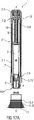
- FIG 1A is a longitudinal section of an exemplary embodiment of an autoinjector 1 according to the present invention during assembly.
- the autoinjector 1 comprises a case 2 comprising a front case 2.1 and a rear case 2.2.
- the case 2 is adapted to hold a medicament container, such as a syringe 3.
- the syringe 3 may be a pre-filled syringe and have a needle 4 arranged at a distal end.
- a protective needle sheath 5 may be removably coupled to the needle 4.
- the protective needle sheath 5 may be a rubber needle sheath or a rigid needle sheath (which is composed of rubber and a full or partial plastic shell).
- a stopper 6 is arranged for sealing the syringe 3 proximally and for displacing a medicament M contained in the syringe 3 through the needle 4.
- the medicament container may be a cartridge which includes the medicament M and engages a removable needle (e.g., by threads, snaps, friction, etc.).
- a cap 11 may be removably disposed at a distal end of the case 2.
- the cap 11 may include an element (e.g., a barb, a hook, a narrowed section, etc.) arranged to engage the protective needle sheath 5, the case 2 and/or a needle shroud 7 telescoped within the case 2.
- the cap 11 may comprise grip features 11.5 for facilitating removal of the cap 11 (e.g., by twisting and/or pulling the cap 11.5 relative to the case 2).
- a shroud spring 8 is arranged to bias the needle shroud 7 in a distal direction D against the case 2.
- a drive spring 9 is arranged within the case 2.
- a plunger 10 serves for forwarding a force of the drive spring 9 to the stopper 6.
- the plunger 10 is hollow and the drive spring 9 is arranged within the plunger 10 biasing the plunger 10 in the distal direction D against the case 2.
- the plunger 10 may be solid and the drive spring 9 may engage a proximal end of the plunger 10.
- a plunger release mechanism 12 is arranged for preventing release of the plunger 10 prior to retraction of the needle shroud 7 relative to the case 2 and for releasing the plunger 10 once the needle shroud 7 is sufficiently retracted.
- a first shroud lock mechanism 14 is arranged to prevent retraction of the needle shroud 7 relative to the case 2 when the cap 11 is in place, thereby avoiding unintentional activation of the autoinjector 1 (e.g., if dropped, during shipping or packaging, etc.).
- the first shroud lock mechanism 14 may comprise one or more compliant beams 11.3 on the cap 11 and a respective number of apertures 7.6 in the needle shroud 7 adapted to receive each of the compliant beams 11.3.
- the compliant beams 11.3 abut a radial stop 2.15 on the case 2 which prevents the compliant beams 11.3 from disengaging the apertures 7.6.
- the compliant beams 11.3 may abut an edge of the aperture 7.6 and deflect to disengage the aperture 7.6, allowing for removal of the cap 11 and the protective needle sheath 5 attached thereto.
- the compliant beams 11.3 and/or the apertures 7.6 may be ramped to reduce force necessary to disengage the compliant beams 11.3 from the apertures 7.6.
- Figure 1B is a schematic side view of an exemplary embodiment of the autoinjector 1 according to the prevent invention during assembly.
- the case 2 is removed for clarity.
- Figure 1B and Figure 2 show a second shroud lock mechanism 15 that is adapted to lock the needle shroud 7 in an axial position relative to the case 2 after the autoinjector 1 has been removed from the injection site.
- the second shroud lock mechanism 15 comprises at least one compliant shroud beam 7.1 on the needle shroud 7 adapted to proximally abut a stop 2.12 on the case 2 after the autoinjector 1 has been removed from the injection site.
- the abutment of the shroud beam 7.1 on the stop 2.12 prevents translation of the needle shroud 7 in the proximal direction P relative to the case 2.
- the cap 11 Prior to use, when the cap 11 is attached to the autoinjector 1, the cap 11 is adapted to engage and deflect the compliant shroud beam 7.1 radially inward, allowing the shroud beam 7.1 to pass the stop 2.12 in the proximal direction P so that the needle shroud 7 can translate in the proximal direction P relative to the case 2.
- the autoinjector 1 may formed from at least two subassemblies, e.g., a control subassembly 1.1 and a drive subassembly 1.2, to allow for flexibility as to the time and location of manufacture of the subassemblies 1.1, 1.2 and final assembly with the syringe 3.
- FIG 3 is a perspective exploded view of an exemplary embodiment of a control subassembly 1.1 of an autoinjector 1 according to the present invention.
- the control subassembly 1.1 comprises the cap 11, the needle shroud 7, the shroud spring 8 and the front case 2.1.
- the shroud spring 8 is inserted into the needle shroud 7, and the needle shroud 7 with the shroud spring 8 is inserted into the front case 2.1.
- the cap 11 is arranged over the distal end of the needle shroud 7.
- FIG. 4 is a perspective exploded view of an exemplary embodiment of a drive subassembly 1.2 of an autoinjector 1 according to the present invention.
- the drive subassembly 1.2 the plunger 10, the drive spring 9 and the rear case 2.2.
- the drive spring 9 is inserted into the plunger 10 and the plunger 10 is inserted in the rear case 2.2 in the proximal direction P thereby compressing the drive spring 9.
- the plunger 10 and the drive spring 9 reach a compressed position it is rotated by an angle, e.g. approximately 30° relative to the rear case 2.2, to engage the plunger 10 to the rear case 2.2.
- the rear case 2.2 may have a cam surface to engage the plunger 10 to induce this rotation prior to the plunger 10 and the drive spring 9 reaching the compressed position.
- FIG. 5 is a perspective view of an exemplary embodiment of a needle sheath removal mechanism 13 of an autoinjector 1 according to the present invention.
- the needle sheath removal mechanism 13 comprises an opening 11.1 axially arranged in the cap 11.
- the opening 11.1 is approximately sized and shaped to receive the protective needle sheath 5.
- One or more bosses 11.2 may be disposed on a proximal end of the cap 11 and adapted to abut the protective needle sheath 5. For example, when the protective needle sheath 5 is inserted into the opening 11.1, the protective needle sheath 5 may deform around the bosses 11.2.
- the bosses 11.2 may be ramped to reduce force necessary to insert the protective needle sheath 5 into the opening 11.1.
- the bosses 11.2 may abut a proximal end of the protective needle sheath 5 to prevent translation of the protective needle sheath 5 in the proximal direction P relative to the cap 11.
- the bosses 11.2 on the cap 11 may abut the proximal end of the protective needle sheath 5 and push the protective needle sheath 5 in the distal direction D off of the needle 4. with their non-ramped distal face.
- Figure 6 is a schematic view of an exemplary embodiment of a plunger release mechanism 12 of the autoinjector 1 according to the present invention during assembly.
- the plunger release mechanism 12 is arranged for preventing release of the plunger 10 prior to retraction of the needle shroud 7 relative to the case 2 and for releasing the plunger 10 once the needle shroud 7 is sufficiently retracted.
- the plunger release mechanism 12 comprises the plunger 10, the rear case 2.2, and the needle shroud 7 interacting with each other.
- the needle shroud 7 is limited to axial movement relative to the case 2, and the plunger 10 can translate axially and rotate relative to the case 2.
- the plunger 10 comprises a first plunger boss 10.1 adapted to engage a shroud rib 7.7 on the needle shroud 7, a second plunger boss 10.2 adapted to engage a case slot 2.3 in the case 2, and a plunger rib 10.3 adapted to engage the shroud rib 7.7 on the needle shroud 7.
- the shroud rib 7.7 comprises a proximal face 7.8 adapted to engage the plunger rib 10.3, and a distal face 7.9 and a longitudinal face 7.10 adapted to engage the first plunger boss 10.1.
- a receiving element may be formed on the needle shroud 7 distal of the longitudinal face 7.10 of the shroud rib 7.7.
- the case slot 2.3 comprises a first angled surface 2.9 adapted to apply a rotational force in a first rotational direction R1 to the second plunger boss 10.2, a wall 2.10 adapted to abut the second plunger boss 10.2 to limit rotation of the plunger 10 relative to the case 2 in the first rotational direction R1, and a second angled surface 2.11 adapted to apply a rotational force in a second rotational direction R2, opposite the first rotational direction R1, to the second plunger boss 10.2.
- the plunger 10 with the drive spring 9 is inserted into the rear case 2.2.
- the plunger 10 is rotated in the first rotational direction R1 until the second plunger boss 10.2 is moved into the case slot 2.3 until it abuts the wall 2.10.
- the first angled surface 2.9 prevents the second plunger boss 10.2 from moving in the second rotational direction R2, and thus prevents the plunger 10 from rotating relative to the case 2.
- a pair of resilient beams 2.13 (shown in Figure 1 B) on the rear case 2.2 is adapted to snap into recesses 2.14 (shown in Figure 3 ) in the front case 2.1 to lock the drive subassembly 1.2 to the control subassembly 1.1.
- the needle shroud 7 translates proximally (e.g., by use of an assembly jig) causing the shroud rib 7.7 to abut the plunger rib 10.3.
- the angle of the plunger rib 10.3 causes the plunger 10 to rotate relative to the case 2 in the second rotational direction R2, and the second plunger boss 10.2 rides along the first angled surface 2.9 onto the second angled surface 2.11.
- the force of the drive spring 9 imparts a rotational force on the plunger 10 in the second rotational direction R2 due to the angle of the second angled surface 2.11.
- the needle shroud 7 when the needle shroud 7 is released (e.g., by removing the assembly jig), the needle shroud 7 translates in the distal direction D relative to the case 2 under the force the shroud spring 8 until the shroud rib 7.7 abuts the first plunger boss 10.1.
- the distal face 7.9 of the shroud rib 7.7 may abut the first plunger boss 10.1 and maintain the needle shroud 7 in an axial position relative to the case 2.
- the second plunger boss 10.2 is prevented from disengaging the case slot 2.3, because the shroud rib 7.7 prevents the plunger 10 from rotating in the second rotational direction R2 relative to the case 2.
- the longitudinal face 7.10 of the shroud rib 7.7 abuts the first plunger boss 10.1 to prevent rotation of the plunger 10.
- Figure 9 shows an exemplary embodiment of the first shroud lock mechanism 14 for an autoinjector 1 according to the present invention after assembly of the control subassembly 1.1.
- the compliant beam 11.3 on the cap is engaged in the aperture 7.6 within the needle shroud 7.
- the radial stop 2.15 is axially spaced from the compliant beam 11.3.
- Figure 10 shows an exemplary embodiment of the first shroud lock mechanism 14 for an autoinjector 1 according to the present invention during insertion of the syringe 3 into the control subassembly 1.1 for engaging the protective needle sheath 5 to the cap 11.
- the aperture 7.6 provides some clearance allowing a movement of the needle shroud 7 relative to the cap 11 in the distal direction D.
- the front case 2.1 is also moved in the distal direction D relative to the cap 11 axially aligning the radial stop 2.15 with the compliant beam 11.3 preventing the cap 11 from disengaging the needle shroud 7.
- Figure 11 shows an exemplary embodiment of the first shroud lock mechanism 14 for an autoinjector 1 according to the present invention, wherein after insertion of the syringe 3, the needle shroud 7 is moved further in the proximal direction P relative to the front case 2.1 by an assembly jig (not illustrated).
- the drive subassembly 1.2 may be assembled to the control subassembly 1.1.
- the compliant beam 11.3 remains engaged in the aperture 7.6 and the radial stop 2.15 prevents them from disengaging.
- the assembly jig is removed allowing the needle shroud 7 to move back in the distal direction D relative to the front case 2.1 under the force of the shroud spring 8 arriving again in the state illustrated in figure 10 .
- the needle shroud 7 is prevented from moving in the proximal direction P relative to the case 2, because the radial stop 2.15 prevents the compliant beam 11.3 from disengaging the aperture 7.6 and the rib 11.4 on the cap 11 proximally abuts the front case 2.1.
- Figure 12 shows an exemplary embodiment of the second shroud lock mechanism 15 for an autoinjector 1 according to the present invention after assembly of the control subassembly 1.1.
- the needle shroud 7 is partially inserted into the cap 11.
- the shroud beam 7.1 is in a non-deflected position proximally abutting the stop 2.12 in the front case 2.1. This prevents the needle shroud 7 from moving further in the proximal direction P relative to the front case 2.1 and keeps the control subassembly 1.1 locked together.
- Figure 13 shows an exemplary embodiment of the second shroud lock mechanism 15 for an autoinjector 1 according to the present invention during insertion of the syringe 3 into the control subassembly 1.1, wherein the needle shroud 7 is moved further in the distal direction D into the cap 11 such that the cap 11 radially inwardly deflects the shroud beam 7.1 out of its abutment with the stop 2.12.
- the needle shroud 7 is thus free to move in the proximal direction P relative to the front case 2.1.
- Figure 14 shows an exemplary embodiment of the second shroud lock mechanism 15 for an autoinjector 1 according to the present invention after final assembly of the drive subassembly 1.2 to the control subassembly 1.1.
- the needle shroud 7 has been moved further in the proximal direction P relative the front case 2.1 by an assembly jig (not illustrated).
- the drive subassembly 1.2 may be assembled to the control subassembly 1.1.
- the assembly jig is removed and the needle shroud 7 translates in the distal direction D relative to the front case 2.1 under the force of the shroud spring 8 until the shroud rib 7.7 abuts the first plunger boss 10.1.
- the shroud beam 7.1 is prevented from deflecting radially outward by the stop 2.12 in the front case 2.1.
- Figure 15A is a longitudinal section of an exemplary embodiment of an autoinjector 1 according to the present invention after final assembly
- Figure 15B is a schematic side view of an exemplary embodiment of an autoinjector 1 according to the present invention after final assembly, wherein the case 2 is removed for clarity.
- the autoinjector 1 may be kept in temperature controlled environment (e.g., cold chain storage) to, for example, reduce creep in highly stressed components, e.g. under load from the drive spring 9.
- temperature controlled environment e.g., cold chain storage
- the autoinjector 1 is removed from the packaging.
- the medicament in the syringe 3 may be visually inspected through a viewing window (not shown), which can be a transparent part of the case 2 or a cut-out in the case 2 aligned with the syringe 3.
- the cap 11 is removed by pulling it in the distal direction D away from the case 2.
- the bosses 11.2 on the cap 11 frictionally engage the protective needle sheath 5 and pull it off the needle 4 as the cap 11 is pulled in the distal direction D, and the compliant beam 11.3 disengages the aperture 7.6 in the needle shroud 7, as shown in Figure 16 .
- the compliant beam 11.3 translates distally within the aperture 7.6 until it is no longer abutted radially by the radial stop 2.15 and engages a proximal surface of the aperture 7.6 (which may be ramped) and deflects radially to disengage the aperture 7.6.
- the syringe 3 is fixed in position relative to the case 2, so pulling the cap 11 in the distal direction D does not cause any axial movement of the syringe 3.
- the syringe 3 is also fixedly rotationally relative to the case 2 (e.g., by an interference fit with the case 2 and/or the needle shroud 7).
- Figure 17A is a longitudinal section of an exemplary embodiment of the autoinjector 1 according to the present invention prior to use.
- Figure 17B is a schematic side view of an exemplary embodiment of the autoinjector 1 according to the present invention prior to use, wherein the case 2 is removed for clarity.
- the needle shroud 7 When the cap 11 is removed, the needle shroud 7 is in a first extended position FEP relative to the case 2, protruding from the case 2 in the distal direction D.
- the first extended position FEP is defined by the first plunger boss 10.1 abutting the shroud rib 7.7.
- Figure 18A is a longitudinal section of an exemplary embodiment of the autoinjector 1 according to the present invention during use.
- Figure 18B is a schematic side view of an exemplary embodiment of the autoinjector 1 according to the present invention during use, wherein the case 2 is removed for clarity.
- the needle shroud 7 When the autoinjector 1 is pressed against an injection site, the needle shroud 7 translates proximally relative to the case 2 against the biasing force of the shroud spring 8 from the first extended position FEP to a retracted position RP, as shown in Figures 18A and 18B .
- Figure 19 shows an exemplary embodiment of the plunger release mechanism 12 when the needle shroud 7 is in the retracted position RP.
- the needle shroud 7 translates distally causing the first plunger boss 10.1 to, starting from the position shown in figure 8 , ride along the shroud rib 7.7 until it is distal of the shroud rib 7.7.
- the plunger 10 is no longer prevented from rotating in the second rotational direction R2 relative to the case 2.
- the needle shroud 7 may include an aperture, a recess or a slot proximal of the shroud rib 7.7 to accommodate the first plunger boss 10.1 when the needle shroud 7 is in the retracted position RP and the plunger 10 rotates relative to the case 2.
- the shroud rib 7.7 may include a resistance feature (e.g., a projection, a ramp, a recess, etc.) adapted to abut the first plunger boss 10.1 as the needle shroud 7 translates from the first extended position FEP to the retracted position RP.
- a resistance feature e.g., a projection, a ramp, a recess, etc.
- a tactile feedback is provided in the form of increased resistance to pressing the autoinjector 1 against the injection site. The tactile feedback may be used to indicate that needle 4 will be inserted into the injection site upon further depression of the autoinjector 1 against the injection site.
- the needle shroud and reposition as the needle shroud 7 will re-extend to its initial position under the force of the shroud spring 8.
- the needle shroud 7 is in the retracted position RP, the needle 4 has been inserted into the injection site.
- a penetration depth of the needle 4 may be varied by, for example, limiting retraction of the needle shroud 7 relative to the case 2, modifying an axial position of the syringe 3 relative to the case 2, modifying a length of the needle 4, etc.
- the autoinjector 1 of the present invention may be used for sub-cutaneous, intra-dermal and/or intra-muscular injection.
- Figure 20A is a longitudinal section of an exemplary embodiment of the autoinjector 1 according to the present invention during use.
- Figure 20B is a schematic side view of an exemplary embodiment of the autoinjector 1 according to the present invention during use, wherein the case 2 is removed for clarity.
- the plunger 10 When the plunger 10 has rotated a sufficient distance in the second rotational direction R2 such that the second plunger boss 10.2 disengages the case slot 2.3, the plunger 10 is free to translate axially, under the force of the drive spring 9, relative to the case 2 to push the stopper 6 to deliver the medicament M from the syringe 3 through the needle 4.
- disengagement of the first plunger boss 10.1 from the shroud rib 7.7 and/or the second plunger boss 10.2 from the case slot 2.3 may provide an audible feedback indicating that delivery of the medicament M has started.
- a viewing window in the case 2 may allow for a visual feedback that the plunger 10 is advancing within the syringe 3 for assessing the progress of displacement of the medicament M.
- Figure 21A is a longitudinal section of an exemplary embodiment of the autoinjector 1 according to the present invention after use.
- Figure 21B is a schematic side view of an exemplary embodiment of the autoinjector 1 according to the present invention after use, wherein the case 2 is removed for clarity.
- the needle shroud 7 When the autoinjector 1 is removed from the injection site, the needle shroud 7 translates distally relative to the case 2 from the retracted position RP to a second extended position SEP under the biasing force of the shroud spring 8.
- the needle shroud 7 In the second extended position SEP, the needle shroud 7 extends beyond a distal tip of the needle 4 and locks in an axial position relative to the case 2.
- the second extended position SEP prevents needle-stick injury and may also indicate that the autoinjector 1 has been used (because the needle shroud 7 cannot move proximally from the second extended position SEP).
- the needle shroud 7 protrudes further, e.g. 2 mm, from the case 2 than in the first extended position FEP.
- the needle shroud 7 may include an indicia (e.g., a red ring, text, a graphic) on a portion which is visually accessible when the needle shroud 7 is in the second extended position SEP but not in the first extended position FEP.
- the indicia may indicate that the autoinjector 1 has been used.
- FIG 22 is a schematic view of an exemplary embodiment of the second shroud lock mechanism 15 according to the present invention.
- the shroud beam 7.1 passes the stop 2.12 in the distal direction D and relaxes radially outwards which is possible as the cap 11 is no longer present.
- the needle shroud 7 cannot translate proximally relative to the case 2, because the shroud beam 7.1 abuts the stop 2.12. The needle shroud 7 is thus locked in the second extended position SEP.
- Extension of the needle shroud 7 distally beyond the second extended position SEP may be prevented by a shroud boss 7.2 on the needle shroud 7 that abuts a case boss 2.8 on the case 2 (see Figure 1 ).
- Figures 23A to 23E are schematic views of another exemplary embodiment of a plunger release mechanism 12 of the autoinjector 1 according to the present invention.
- the plunger release mechanism 12 is arranged for preventing release of the plunger 10 prior to retraction of the needle shroud 7 relative to the case 2 and for releasing the plunger 10 once the needle shroud 7 is sufficiently retracted.
- the plunger release mechanism 12 comprises the plunger 10, the rear case 2.2, and the needle shroud 7.
- the needle shroud 7 is limited to axial movement relative to the case 2, and the plunger 10 can translate axially and rotate relative to the case 2.
- the plunger 10 comprises a first plunger boss 10.1 adapted to engage a shroud rib 7.7 on the needle shroud 7, a second plunger boss 10.2 adapted to engage a case slot 2.3 in the case 2, and a plunger rib 10.3 adapted to engage the shroud rib 7.7 on the needle shroud 7.
- the shroud rib 7.7 is disposed in a plane substantially perpendicular to a longitudinal axis of the case 2.
- the shroud 7.7 comprises a proximal face 7.8 adapted to engage the plunger rib 10.3, and a distal face 7.9 adapted to engage the first plunger boss 10.1.
- the case slot 2.3 comprises a first angled surface 2.9 adapted to apply a rotational force in a first rotational direction R1 to the second plunger boss 10.2, a wall 2.10 adapted to abut the second plunger boss 10.2 to limit rotation of the plunger 10 relative to the case 2 in the first rotational direction R1, and a transversal surface 2.16 disposed in a plane substantially perpendicular to a longitudinal axis of the case 2.
- Figure 23A is a schematic view of an exemplary embodiment of the plunger release mechanism 12 of the autoinjector 1 according to the present invention during assembly of the drive subassembly 1.2.
- the plunger 10 with the drive spring 9 is inserted into the rear case 2.2.
- the plunger 10 is rotated in the first rotational direction R1 until the second plunger boss 10.2 is moved into the case slot 2.3 until it abuts the wall 2.10.
- the first angled surface 2.9 prevents the second plunger boss 10.2 from moving in the second rotational direction R2, and thus prevents the plunger 10 from rotating relative to the case 2.
- a pair of resilient beams 2.13 (shown in Figure 1 B) on the rear case 2.2 is adapted to snap into recesses 2.14 (shown in Figure 3 ) in the front case 2.1 to lock the drive subassembly 1.2 to the control subassembly 1.1.
- Figure 23B shows the drive assembly 1.2 being coupled to the control subassembly 1.1, wherein the needle shroud 7 translates proximally (e.g., by use of an assembly jig) causing the shroud rib 7.7 to abut the plunger rib 10.3.
- the angle of the plunger rib 10.3 causes the plunger 10 to rotate relative to the case 2 in the second rotational direction R2, and the second plunger boss 10.2 rides along the first angled surface 2.9 onto the transversal surface 2.16.
- the needle shroud 7 when the needle shroud 7 is released (e.g., by removing the assembly jig), the needle shroud 7 translates in the distal direction D relative to the case 2 under the force of the shroud spring 8 until the shroud rib 7.7 abuts the first plunger boss 10.1.
- the distal face 7.9 of the shroud rib 7.7 may abut the first plunger boss 10.1 and maintain the needle shroud 7 in an axial position relative to the case 2.
- the second plunger boss 10.2 is prevented from disengaging the case slot 2.3 as it abuts the transversal surface 2.16 in the distal direction D.
- Figure 23E shows an exemplary embodiment of the plunger release mechanism 12 when the needle shroud 7 is in the retracted position RP.
- the needle shroud 7 translates distally causing the shroud rib 7.7 to, starting from the position shown in figure 23D , ride along the plunger rib 10.3 thereby rotating the second plunger boss 10.2 in the second rotational direction R2 along the transversal surface 2.16 until the second plunger boss 10.2 disengages the case slot 2.3 thus releasing the plunger 10.
- the plunger 10 translates axially relative to the case 2 to deliver the medicament M from the syringe 3.
- a tactile feedback may be provided in the form of an increase in resistance when the needle shroud 7 abuts and pushes against the plunger rib 10.3.
- the tactile feedback may indicate that needle insertion will commence or medicament delivery will be initiated if the autoinjector 1 is pressed further against the injection site.
- transversal surface 2.16 could be replaced by or comprise a concave shape for preventing inadvertent release of the plunger 10.
- the plunger 10 may not have the first plunger boss 10.1, the plunger rib 10.3 may be disposed at different angle than as described above, and the case slot 2.3 may not be angled relative to a transverse axis of the case 2.
- the plunger 10 when the autoinjector 1 is assembled, the plunger 10 is maintained in axial position relative to the case 2, because the second plunger boss 10.2 engages the case slot 2.3.
- case slot 2.3 may not impart any rotational force on the second plunger boss 10.2 (or, in another exemplary embodiment, the case slot 2.3 may be angled to impart a rotational force on the second plunger boss 10.2 in the first rotational direction R1 to ensure that the second plunger boss 10.2 does not disengage the case slot 2.3 inadvertently).
- a tamper strip (not shown) may be arranged between the cap 11 and the front case 2.1 when the control subassembly 1.1 is assembled.
- the tamper strip may be useful for quality assurance.
- a force required to press the needle shroud 7 may be approximately 2-12 N.
- the syringe 3 used in the autoinjector 1 may be a syringe capable of containing approximately 1mL of the medicament M. In another exemplary embodiment, the syringe 3 used in the autoinjector 1 may be a syringe capable of containing approximately 2mL of the medicament M.
- the autoinjector 1 according to the present invention may have an increased shelf-life compared to conventional autoinjectors, because, for example, only the plunger 10 is subjected to the relatively high force of the drive spring 9.
- the autoinjector 1 according to the present invention may be used as a platform as the drive spring 9 can be changed to alter a force applied to the plunger 10, e.g., for delivering medicaments with different viscosities drugs or reconstituted medicaments, or changing a time required to inject a dose of the medicament.
- drug or “medicament”, as used herein, means a pharmaceutical formulation containing at least one pharmaceutically active compound, wherein in one embodiment the pharmaceutically active compound has a molecular weight up to 1500 Da and/or is a peptide, a proteine, a polysaccharide, a vaccine, a DNA, a RNA, an enzyme, an antibody or a fragment thereof, a hormone or an oligonucleotide, or a mixture of the above-mentioned pharmaceutically active compound, wherein in a further embodiment the pharmaceutically active compound is useful for the treatment and/or prophylaxis of diabetes mellitus or complications associated with diabetes mellitus such as diabetic retinopathy, thromboembolism disorders such as deep vein or pulmonary thromboembolism, acute coronary syndrome (ACS), angina, myocardial infarction, cancer, macular degeneration, inflammation, hay fever, atherosclerosis and/or rheumatoid arthritis, wherein in a further
- Insulin analogues are for example Gly(A21), Arg(B31), Arg(B32) human insulin; Lys(B3), Glu(B29) human insulin; Lys(B28), Pro(B29) human insulin; Asp(B28) human insulin; human insulin, wherein proline in position B28 is replaced by Asp, Lys, Leu, Val or Ala and wherein in position B29 Lys may be replaced by Pro; Ala(B26) human insulin; Des(B28-B30) human insulin; Des(B27) human insulin and Des(B30) human insulin.
- Insulin derivates are for example B29-N-myristoyl-des(B30) human insulin; B29-N-palmitoyl-des(B30) human insulin; B29-N-myristoyl human insulin; B29-N-palmitoyl human insulin; B28-N-myristoyl LysB28ProB29 human insulin; B28-N-palmitoyl-LysB28ProB29 human insulin; B30-N-myristoyl-ThrB29LysB30 human insulin; B30-N-palmitoyl- ThrB29LysB30 human insulin; B29-N-(N-palmitoyl-Y-glutamyl)-des(B30) human insulin; B29-N-(N-lithocholyl-Y-glutamyl)-des(B30) human insulin; B29-N-( ⁇ -carboxyheptadecanoyl)-des(B30) human insulin and B29-N-( ⁇ -carbox
- Exendin-4 for example means Exendin-4(1-39), a peptide of the sequence H-His-Gly-Glu-Gly-Thr-Phe-Thr-Ser-Asp-Leu-Ser-Lys-Gln-Met-Glu-Glu-Glu-Ala-Val-Arg-Leu-Phe-Ile-Glu-Trp-Leu-Lys-Asn-Gly-Gly-Pro-Ser-Ser-Gly-Ala-Pro-Pro-Pro-Ser-NH2.
- Exendin-4 derivatives are for example selected from the following list of compounds:
- Hormones are for example hypophysis hormones or hypothalamus hormones or regulatory active peptides and their antagonists as listed in Rote Liste, ed. 2008, Chapter 50 , such as Gonadotropine (Follitropin, Lutropin, Choriongonadotropin, Menotropin), Somatropine (Somatropin), Desmopressin, Terlipressin, Gonadorelin, Triptorelin, Leuprorelin, Buserelin, Nafarelin, Goserelin.
- Gonadotropine Follitropin, Lutropin, Choriongonadotropin, Menotropin
- Somatropine Somatropin
- Desmopressin Terlipressin
- Gonadorelin Triptorelin
- Leuprorelin Buserelin
- Nafarelin Goserelin.
- a polysaccharide is for example a glucosaminoglycane, a hyaluronic acid, a heparin, a low molecular weight heparin or an ultra low molecular weight heparin or a derivative thereof, or a sulphated, e.g. a poly-sulphated form of the above-mentioned polysaccharides, and/or a pharmaceutically acceptable salt thereof.
- An example of a pharmaceutically acceptable salt of a poly-sulphated low molecular weight heparin is enoxaparin sodium.
- Antibodies are globular plasma proteins ( ⁇ 150 kDa) that are also known as immunoglobulins which share a basic structure. As they have sugar chains added to amino acid residues, they are glycoproteins.
- the basic functional unit of each antibody is an immunoglobulin (Ig) monomer (containing only one Ig unit); secreted antibodies can also be dimeric with two Ig units as with IgA, tetrameric with four Ig units like teleost fish IgM, or pentameric with five Ig units, like mammalian IgM.
- Ig immunoglobulin
- the Ig monomer is a "Y"-shaped molecule that consists of four polypeptide chains; two identical heavy chains and two identical light chains connected by disulfide bonds between cysteine residues. Each heavy chain is about 440 amino acids long; each light chain is about 220 amino acids long. Heavy and light chains each contain intrachain disulfide bonds which stabilize their folding. Each chain is composed of structural domains called Ig domains. These domains contain about 70-110 amino acids and are classified into different categories (for example, variable or V, and constant or C) according to their size and function. They have a characteristic immunoglobulin fold in which two ⁇ sheets create a "sandwich" shape, held together by interactions between conserved cysteines and other charged amino acids.
- Ig heavy chain There are five types of mammalian Ig heavy chain denoted by ⁇ , ⁇ , ⁇ , ⁇ , and ⁇ .
- the type of heavy chain present defines the isotype of antibody; these chains are found in IgA, IgD, IgE, IgG, and IgM antibodies, respectively.
- Distinct heavy chains differ in size and composition; ⁇ and ⁇ contain approximately 450 amino acids and ⁇ approximately 500 amino acids, while ⁇ and ⁇ have approximately 550 amino acids.
- Each heavy chain has two regions, the constant region (C H ) and the variable region (V H ).
- the constant region is essentially identical in all antibodies of the same isotype, but differs in antibodies of different isotypes.
- Heavy chains ⁇ , ⁇ and ⁇ have a constant region composed of three tandem Ig domains, and a hinge region for added flexibility; heavy chains ⁇ and ⁇ have a constant region composed of four immunoglobulin domains.
- the variable region of the heavy chain differs in antibodies produced by different B cells, but is the same for all antibodies produced by a single B cell or B cell clone.
- the variable region of each heavy chain is approximately 110 amino acids long and is composed of a single Ig domain.
- a light chain has two successive domains: one constant domain (CL) and one variable domain (VL).
- CL constant domain
- VL variable domain
- the approximate length of a light chain is 211 to 217 amino acids.
- Each antibody contains two light chains that are always identical; only one type of light chain, ⁇ or ⁇ , is present per antibody in mammals.
- variable (V) regions are responsible for binding to the antigen, i.e. for its antigen specificity.
- VL variable light
- VH variable heavy chain
- CDRs Complementarity Determining Regions
- an "antibody fragment” contains at least one antigen binding fragment as defined above, and exhibits essentially the same function and specificity as the complete antibody of which the fragment is derived from.
- Limited proteolytic digestion with papain cleaves the Ig prototype into three fragments. Two identical amino terminal fragments, each containing one entire L chain and about half an H chain, are the antigen binding fragments (Fab).
- the Fc contains carbohydrates, complement-binding, and FcR-binding sites.
- F(ab')2 is divalent for antigen binding.
- the disulfide bond of F(ab')2 may be cleaved in order to obtain Fab'.
- the variable regions of the heavy and light chains can be fused together to form a single chain variable fragment (scFv).
- Pharmaceutically acceptable salts are for example acid addition salts and basic salts.
- Acid addition salts are e.g. HCl or HBr salts.
- Basic salts are e.g. salts having a cation selected from alkali or alkaline, e.g. Na+, or K+, or Ca2+, or an ammonium ion N+(R1)(R2)(R3)(R4), wherein R1 to R4 independently of each other mean: hydrogen, an optionally substituted C1-C6-alkyl group, an optionally substituted C2-C6-alkenyl group, an optionally substituted C6-C10-aryl group, or an optionally substituted C6-C10-heteroaryl group.
- solvates are for example hydrates.
- An autoinjector (1) comprising:
- the autoinjector (1) with the features of embodiment 1, wherein the needle shroud (7) is movable from the retracted position (RP) to a second extended position (SEP) relative to the case (2) in which the needle (4) is covered and the needle shroud (7) cannot translate relative to the case (2).
- RP retracted position
- SEP second extended position
- the autoinjector (1) with the features of embodiment 1 or 2, further comprising:
- the autoinjector (1) with the features of embodiment 3, wherein the cap (11) includes an element adapted to engage a protective needle sheath (5) removably disposed on the needle (4).
- the autoinjector (1) with the features of embodiment 3, wherein the cap (11) includes at least one compliant beam (11.3) adapted to releasably engage at least one radial aperture (7.6) in the needle shroud (7).
- the autoinjector (1) with the features of embodiment 5, wherein, when the cap (11) is coupled to the case (2), the at least one complaint beam (11.3) engages the at least one radial aperture (7.6) in the needle shroud (7) and radially abuts the case (2).
- the autoinjector (1) with the features of embodiment 5, wherein, when the cap (11) is removed from the case (2), the at least one complaint beam (11.3) disengages the at least one radial aperture (7.6) in the needle shroud (7) and no longer radially abuts the case (2).
- the autoinjector (1) with the features of any one of embodiments 1 to 7, further comprising:
- the autoinjector (1) with the features of any one of embodiments 1 to 8, further comprising:
- the autoinjector (1) with the features of embodiment 9, wherein the plunger (10) translates relative to the case (2) under force of the drive spring (9) when the plunger (10) is in the second rotational position and the needle shroud (7) is in the retracted position (RP).
- the autoinjector (1) with the features of embodiment 9, wherein the plunger (10) is at least partially hollow and the drive spring (9) is at least partially disposed within the plunger (10).
- the needle shroud (7) includes at least one complaint shroud beam (7.1) radially abutting the case (2) when the needle shroud (7) is in the first extended position (FEP) and the retracted position (RP), wherein the at least one complaint shroud beam (7.1) deflects radially when the needle shroud (7) is in the second extended position (SEP) and axially abuts the case (2).
- the autoinjector (1) with the features of any one of embodiments 1 to 12, wherein the plunger (10) includes a first plunger boss (10.1) adapted to engage a shroud rib (7.7) disposed on the needle shroud (7) and a second plunger boss (10.2) adapted to engage a case slot (2.3) in the case (2).
- the plunger (10) includes a first plunger boss (10.1) adapted to engage a shroud rib (7.7) disposed on the needle shroud (7) and a second plunger boss (10.2) adapted to engage a case slot (2.3) in the case (2).
- the autoinjector (1) with the features of embodiment 13, wherein, when the plunger (10) is in the first rotational position and the needle shroud (7) is in the first extended position (FEP), the first plunger boss (10.1) engages the shroud rib (7.7) and the second plunger boss (10.2) engages the case slot (2.3).
- the autoinjector (1) with the features of embodiment 14, wherein, when the needle shroud (7) translates from the first extended position (FEP) to the retracted position (RP), the plunger (10) rotates from the first rotational position to the second rotational position and the second plunger boss (10.2) disengages the case slot (2.3).
- the autoinjector (1) with the features of embodiment 15, wherein the shroud rib (7.7) maintains the plunger (10) in the first rotational position when the needle shroud (7) is in the first extended position (FEP).
- the autoinjector (1) with the features of embodiment 16, wherein the needle shroud (7) includes a receiving element adapted to receive the first plunger boss (10.1) when the needle shroud (7) is in the retracted position (RP) and the plunger (10) is in the second rotational position.
- the autoinjector (1) with the features of embodiment 15, wherein, when the needle shroud (7) translates from the first extended position (FEP) to the retracted position (RP), the shroud rib (7.7) engages a plunger rib (10.3) to rotate the plunger (10) from the first rotational position to the second rotational position.
- the autoinjector (1) with the features of embodiment 15, wherein the plunger rib (10.3) is disposed at an angle relative to a longitudinal axis of the case (2).
Landscapes
- Health & Medical Sciences (AREA)
- Vascular Medicine (AREA)
- Engineering & Computer Science (AREA)
- Anesthesiology (AREA)
- Biomedical Technology (AREA)
- Heart & Thoracic Surgery (AREA)
- Hematology (AREA)
- Life Sciences & Earth Sciences (AREA)
- Animal Behavior & Ethology (AREA)
- General Health & Medical Sciences (AREA)
- Public Health (AREA)
- Veterinary Medicine (AREA)
- Infusion, Injection, And Reservoir Apparatuses (AREA)
Abstract
Description
- The invention relates to an autoinjector.
- Administering an injection is a process which presents a number of risks and challenges for users and healthcare professionals, both mental and physical. Injection devices typically fall into two categories - manual devices and autoinjectors. In a conventional manual device, manual force is required to drive a medicament through a needle. This is typically done by some form of button / plunger that has to be continuously pressed during the injection. There are numerous disadvantages associated with this approach. For example, if the button / plunger is released prematurely, the injection will stop and may not deliver an intended dose. Further, the force required to push the button / plunger may be too high (e.g., if the user is elderly or a child). And, aligning the injection device, administering the injection and keeping the injection device still during the injection may require dexterity which some patients (e.g., elderly patients, children, arthritic patients, etc.) may not have.
- Autoinjector devices aim to make self-injection easier for patients. A conventional autoinjector may provide the force for administering the injection by a spring, and trigger button or other mechanism may be used to activate the injection. Autoinjectors may be single-use or reusable devices.
- There remains a need for an improved autoinjector.
- It is an object of the present invention to provide an improved autoinjector.
- In an exemplary embodiment, an autoinjector according to the present invention comprises a case adapted to hold a medicament container having a needle, a needle shroud telescopically coupled to the case and movable between a first extended position relative to the case in which the needle is covered and a retracted position relative to the case in which the needle is exposed, and a plunger rotationally and slidably disposed in the case. The plunger is rotatable relative to the case between a first rotational position in which the plunger is engaged to the case and a second rotational position in which the plunger disengages the case. The needle shroud is operably coupled to the plunger. When the needle shroud translates from the first extended position to the retracted position, the plunger rotates from the first rotational position to the second rotational position.
- In an exemplary embodiment, the needle shroud is movable from the retracted position to a second extended position relative to the case in which the needle is covered and the needle shroud cannot translate relative to the case.
- In an exemplary embodiment, the autoinjector further comprises a cap removably coupled to the case. The cap may include an element adapted to engage a protective needle sheath removably disposed on the needle. The cap may include at least one compliant beam adapted to releasably engage at least one radial aperture in the needle shroud. When the cap is coupled to the case the at least one complaint beam engages the at least one radial aperture in the needle shroud and radially abuts the case. When the cap is removed from the case, the at least one complaint beam disengages the at least one radial aperture in the needle shroud and no longer radially abuts the case.
- In an exemplary embodiment, the autoinjector further comprises a shroud spring biasing the needle shroud in a distal direction relative to the case.
- In an exemplary embodiment, the autoinjector further comprises a drive spring biasing the plunger in a distal direction relative to the case. The plunger translates relative to the case under force of the drive spring when the plunger is in the second rotational position and the needle shroud is in the retracted position. The plunger may be at least partially hollow and the drive spring may be at least partially disposed within the plunger.
- In an exemplary embodiment, the needle shroud includes at least one complaint shroud beam radially abutting the case when the needle shroud is in the first extended position and the retracted position, and the at least one complaint shroud beam deflects radially when the needle shroud is in the second extended position and axially abuts the case.
- In an exemplary embodiment, the plunger includes a first plunger boss adapted to engage a shroud rib disposed on the needle shroud and a second plunger boss adapted to engage a case slot in the case. When the plunger is in the first rotational position and the needle shroud is in the first extended position, the first plunger boss engages the shroud rib and the second plunger boss engages the case slot. When the needle shroud translates from the first extended position to the retracted position, the plunger rotates from the first rotational position to the second rotational position and the second plunger boss disengages the case slot. The shroud rib maintains the plunger in the first rotational position when the needle shroud is in the first extended position. The needle shroud may include a receiving element adapted to receive the first plunger boss when the needle shroud is in the retracted position and the plunger is in the second rotational position.
- In an exemplary embodiment, when the needle shroud translates from the first extended position to the retracted position, the shroud rib engages a plunger rib to rotate the plunger from the first rotational position to the second rotational position. The plunger rib may be disposed at an angle relative to a longitudinal axis of the case.
- Further scope of applicability of the present invention will become apparent from the detailed description given hereinafter. However, it should be understood that the detailed description and specific examples, while indicating preferred embodiments of the invention, are given by way of illustration only, since various changes and modifications within the spirit and scope of the invention will become apparent to those skilled in the art from this detailed description.
- The present invention will become more fully understood from the detailed description given hereinbelow and the accompanying drawings which are given by way of illustration only, and thus, are not limitive of the present invention, and wherein:
- Figure 1A
- is a longitudinal section of an exemplary embodiment of an autoinjector according to the present invention during assembly,
- Figure 1B
- is a schematic side view of an exemplary embodiment of an autoinjector according to the present invention during assembly,
- Figure 2
- is a schematic view of an exemplary embodiment of a shroud lock mechanism of an exemplary embodiment of an autoinjector according to the present invention,
- Figure 3
- is a perspective exploded view of an exemplary embodiment of a control subassembly of an exemplary embodiment of an autoinjector according to the present invention,
- Figure 4
- is a perspective exploded view of an exemplary embodiment of a drive subassembly of an exemplary embodiment of an autoinjector according to the present invention,
- Figure 5
- is a perspective view of an exemplary embodiment of a needle sheath removal mechanism of an exemplary embodiment of an autoinjector according to the present invention,
- Figure 6
- is a schematic view of an exemplary embodiment of a plunger release mechanism of an exemplary embodiment of an autoinjector according to the present invention,
- Figure 7
- is a schematic view of an exemplary embodiment of a plunger release mechanism of an exemplary embodiment of an autoinjector according to the present invention during assembly,
- Figure 8
- is a schematic view of an exemplary embodiment of a plunger release mechanism of an exemplary embodiment of an autoinjector according to the present invention after assembly,
- Figure 9
- is a schematic view of an exemplary embodiment of a shroud lock mechanism of an exemplary embodiment of an autoinjector according to the present invention after assembly,
- Figure 10
- is a schematic view of an exemplary embodiment of shroud lock mechanism of an exemplary embodiment of an autoinjector according to the present invention during assembly,
- Figure 11
- is a schematic view of an exemplary embodiment of shroud lock mechanism of an exemplary embodiment of an autoinjector according to the present invention during assembly,
- Figure 12
- is a schematic view of an exemplary embodiment of shroud lock mechanism of an exemplary embodiment of an autoinjector according to the present invention during assembly,
- Figure 13
- is a schematic view of an exemplary embodiment of shroud lock mechanism of an exemplary embodiment of an autoinjector according to the present invention during assembly,
- Figure 14
- is a schematic view of an exemplary embodiment of shroud lock mechanism of an exemplary embodiment of an autoinjector according to the present invention after assembly,
- Figure 15A
- is a longitudinal section of an exemplary embodiment of an autoinjector according to the present invention after assembly,
- Figure 15B
- is a schematic side view of an exemplary embodiment of an autoinjector according to the present invention after assembly,
- Figure 16
- is a schematic view of an exemplary embodiment of a shroud lock mechanism an exemplary embodiment of an autoinjector according to the present invention prior to use,
- Figure 17A
- is a longitudinal section of an exemplary embodiment of a shroud lock mechanism an exemplary embodiment of an autoinjector according to the present invention prior to use,
- Figure 17B
- is a schematic side view of an exemplary embodiment of a shroud lock mechanism an exemplary embodiment of an autoinjector according to the present invention prior to use,
- Figure 18A
- is a longitudinal section of an exemplary embodiment of an autoinjector according to the present invention during use,
- Figure 18B
- is a schematic side view of an exemplary embodiment of an autoinjector according to the present invention during use,
- Figure 19
- is a schematic view of an exemplary embodiment of a plunger release mechanism of an exemplary embodiment of an autoinjector according to the present invention during use,
- Figure 20A
- is a longitudinal section of an exemplary embodiment of an autoinjector according to the present invention during use,
- Figure 20B
- is a schematic side view of an exemplary embodiment of an autoinjector according to the present invention during use,
- Figure 21A
- is a longitudinal section of an exemplary embodiment of an autoinjector according to the present invention after use,
- Figure 21B
- is a schematic side view of an exemplary embodiment of an autoinjector according to the present invention after use,
- Figure 22
- is a schematic view of an exemplary embodiment of a shroud lock mechanism of an exemplary embodiment of an autoinjector according to the present invention after use, and
- Figures 23A-E
- is a schematic view of another exemplary embodiment of a plunger release mechanism during assembly and before, during and after use.
- Corresponding parts are marked with the same reference symbols in all figures.
-
Figure 1A is a longitudinal section of an exemplary embodiment of an autoinjector 1 according to the present invention during assembly. The autoinjector 1 comprises acase 2 comprising a front case 2.1 and a rear case 2.2. Thecase 2 is adapted to hold a medicament container, such as asyringe 3. Thesyringe 3 may be a pre-filled syringe and have aneedle 4 arranged at a distal end. When the autoinjector 1 and/or thesyringe 3 are assembled, aprotective needle sheath 5 may be removably coupled to theneedle 4. Theprotective needle sheath 5 may be a rubber needle sheath or a rigid needle sheath (which is composed of rubber and a full or partial plastic shell). Astopper 6 is arranged for sealing thesyringe 3 proximally and for displacing a medicament M contained in thesyringe 3 through theneedle 4. In other exemplary embodiments, the medicament container may be a cartridge which includes the medicament M and engages a removable needle (e.g., by threads, snaps, friction, etc.). - In an exemplary embodiment, a
cap 11 may be removably disposed at a distal end of thecase 2. Thecap 11 may include an element (e.g., a barb, a hook, a narrowed section, etc.) arranged to engage theprotective needle sheath 5, thecase 2 and/or aneedle shroud 7 telescoped within thecase 2. Thecap 11 may comprise grip features 11.5 for facilitating removal of the cap 11 (e.g., by twisting and/or pulling the cap 11.5 relative to the case 2). - In an exemplary embodiment, a
shroud spring 8 is arranged to bias theneedle shroud 7 in a distal direction D against thecase 2. - In an exemplary embodiment, a
drive spring 9 is arranged within thecase 2. Aplunger 10 serves for forwarding a force of thedrive spring 9 to thestopper 6. In an exemplary embodiment, theplunger 10 is hollow and thedrive spring 9 is arranged within theplunger 10 biasing theplunger 10 in the distal direction D against thecase 2. In another exemplary embodiment, theplunger 10 may be solid and thedrive spring 9 may engage a proximal end of theplunger 10. - In an exemplary embodiment, a
plunger release mechanism 12 is arranged for preventing release of theplunger 10 prior to retraction of theneedle shroud 7 relative to thecase 2 and for releasing theplunger 10 once theneedle shroud 7 is sufficiently retracted. - In an exemplary embodiment, a first
shroud lock mechanism 14 is arranged to prevent retraction of theneedle shroud 7 relative to thecase 2 when thecap 11 is in place, thereby avoiding unintentional activation of the autoinjector 1 (e.g., if dropped, during shipping or packaging, etc.). The firstshroud lock mechanism 14 may comprise one or more compliant beams 11.3 on thecap 11 and a respective number of apertures 7.6 in theneedle shroud 7 adapted to receive each of the compliant beams 11.3. When thecap 11 is attached to the autoinjector 1, the compliant beams 11.3 abut a radial stop 2.15 on thecase 2 which prevents the compliant beams 11.3 from disengaging the apertures 7.6. When thecap 11 is attached to the autoinjector 1, axial movement of thecap 11 in the proximal direction P relative thecase 2 is limited by a rib 11.4 on thecap 11 abutting thecase 2. When thecap 11 is pulled in the distal direction D relative to thecase 2, the compliant beams 11.3 may abut an edge of the aperture 7.6 and deflect to disengage the aperture 7.6, allowing for removal of thecap 11 and theprotective needle sheath 5 attached thereto. In an exemplary embodiment, the compliant beams 11.3 and/or the apertures 7.6 may be ramped to reduce force necessary to disengage the compliant beams 11.3 from the apertures 7.6. -
Figure 1B is a schematic side view of an exemplary embodiment of the autoinjector 1 according to the prevent invention during assembly. In the exemplary embodiment inFigure 1B , thecase 2 is removed for clarity.Figure 1B andFigure 2 show a secondshroud lock mechanism 15 that is adapted to lock theneedle shroud 7 in an axial position relative to thecase 2 after the autoinjector 1 has been removed from the injection site. In an exemplary embodiment, the secondshroud lock mechanism 15 comprises at least one compliant shroud beam 7.1 on theneedle shroud 7 adapted to proximally abut a stop 2.12 on thecase 2 after the autoinjector 1 has been removed from the injection site. The abutment of the shroud beam 7.1 on the stop 2.12 prevents translation of theneedle shroud 7 in the proximal direction P relative to thecase 2. Prior to use, when thecap 11 is attached to the autoinjector 1, thecap 11 is adapted to engage and deflect the compliant shroud beam 7.1 radially inward, allowing the shroud beam 7.1 to pass the stop 2.12 in the proximal direction P so that theneedle shroud 7 can translate in the proximal direction P relative to thecase 2. - In an exemplary embodiment, the autoinjector 1 may formed from at least two subassemblies, e.g., a control subassembly 1.1 and a drive subassembly 1.2, to allow for flexibility as to the time and location of manufacture of the subassemblies 1.1, 1.2 and final assembly with the
syringe 3. -
Figure 3 is a perspective exploded view of an exemplary embodiment of a control subassembly 1.1 of an autoinjector 1 according to the present invention. In an exemplary embodiment, the control subassembly 1.1 comprises thecap 11, theneedle shroud 7, theshroud spring 8 and the front case 2.1. To assemble the control subassembly 1.1, theshroud spring 8 is inserted into theneedle shroud 7, and theneedle shroud 7 with theshroud spring 8 is inserted into the front case 2.1. Thecap 11 is arranged over the distal end of theneedle shroud 7. -
Figure 4 is a perspective exploded view of an exemplary embodiment of a drive subassembly 1.2 of an autoinjector 1 according to the present invention. In an exemplary embodiment, the drive subassembly 1.2 theplunger 10, thedrive spring 9 and the rear case 2.2. Those of skill in the art will understand that if the viscosity or volume, for example, of the medicament M in thesyringe 3 is changed, only parts of the drive subassembly 1.2 may need to be changed. To assemble the drive subassembly 1.2, thedrive spring 9 is inserted into theplunger 10 and theplunger 10 is inserted in the rear case 2.2 in the proximal direction P thereby compressing thedrive spring 9. Once theplunger 10 and thedrive spring 9 reach a compressed position it is rotated by an angle, e.g. approximately 30° relative to the rear case 2.2, to engage theplunger 10 to the rear case 2.2. In an exemplary embodiment, the rear case 2.2 may have a cam surface to engage theplunger 10 to induce this rotation prior to theplunger 10 and thedrive spring 9 reaching the compressed position. -
Figure 5 is a perspective view of an exemplary embodiment of a needlesheath removal mechanism 13 of an autoinjector 1 according to the present invention. The needlesheath removal mechanism 13 comprises an opening 11.1 axially arranged in thecap 11. The opening 11.1 is approximately sized and shaped to receive theprotective needle sheath 5. One or more bosses 11.2 may be disposed on a proximal end of thecap 11 and adapted to abut theprotective needle sheath 5. For example, when theprotective needle sheath 5 is inserted into the opening 11.1, theprotective needle sheath 5 may deform around the bosses 11.2. The bosses 11.2 may be ramped to reduce force necessary to insert theprotective needle sheath 5 into the opening 11.1. Once theprotective needle sheath 5 has passed the bosses 11.2 in the distal direction D, the bosses 11.2 may abut a proximal end of theprotective needle sheath 5 to prevent translation of theprotective needle sheath 5 in the proximal direction P relative to thecap 11. For example, during removal of thecap 11 from the autoinjector 1, the bosses 11.2 on thecap 11 may abut the proximal end of theprotective needle sheath 5 and push theprotective needle sheath 5 in the distal direction D off of theneedle 4. with their non-ramped distal face. Those of skill in the art will understand that a number of parameters can be varied, e.g. a radial height of the boss 11.2, an axial length of the boss 11.2, an angle of the ramp of the boss 11.2, a durometer of theprotective needle sheath 5, a surface finish of the boss 11.2, etc., which could increase or decrease assembly forces, cap removal forces, etc. -
Figure 6 is a schematic view of an exemplary embodiment of aplunger release mechanism 12 of the autoinjector 1 according to the present invention during assembly. Theplunger release mechanism 12 is arranged for preventing release of theplunger 10 prior to retraction of theneedle shroud 7 relative to thecase 2 and for releasing theplunger 10 once theneedle shroud 7 is sufficiently retracted. In an exemplary embodiment, theplunger release mechanism 12 comprises theplunger 10, the rear case 2.2, and theneedle shroud 7 interacting with each other. In an exemplary embodiment, theneedle shroud 7 is limited to axial movement relative to thecase 2, and theplunger 10 can translate axially and rotate relative to thecase 2. - In an exemplary embodiment, the
plunger 10 comprises a first plunger boss 10.1 adapted to engage a shroud rib 7.7 on theneedle shroud 7, a second plunger boss 10.2 adapted to engage a case slot 2.3 in thecase 2, and a plunger rib 10.3 adapted to engage the shroud rib 7.7 on theneedle shroud 7. In an exemplary embodiment, the shroud rib 7.7 comprises a proximal face 7.8 adapted to engage the plunger rib 10.3, and a distal face 7.9 and a longitudinal face 7.10 adapted to engage the first plunger boss 10.1. A receiving element (e.g., a recess, a hole, etc.) may be formed on theneedle shroud 7 distal of the longitudinal face 7.10 of the shroud rib 7.7. In an exemplary embodiment, the case slot 2.3 comprises a first angled surface 2.9 adapted to apply a rotational force in a first rotational direction R1 to the second plunger boss 10.2, a wall 2.10 adapted to abut the second plunger boss 10.2 to limit rotation of theplunger 10 relative to thecase 2 in the first rotational direction R1, and a second angled surface 2.11 adapted to apply a rotational force in a second rotational direction R2, opposite the first rotational direction R1, to the second plunger boss 10.2. - In an exemplary embodiment of an assembly process of the drive subassembly 1.2, the
plunger 10 with thedrive spring 9 is inserted into the rear case 2.2. When the second plunger boss 10.2 is axially aligned with the case slot 2.3, theplunger 10 is rotated in the first rotational direction R1 until the second plunger boss 10.2 is moved into the case slot 2.3 until it abuts the wall 2.10. In this position, the first angled surface 2.9 prevents the second plunger boss 10.2 from moving in the second rotational direction R2, and thus prevents theplunger 10 from rotating relative to thecase 2. - After a syringe 3 (with the
protective needle sheath 5 disposed on the needle 4) is inserted into the control assembly 1.1, the drive subassembly 1.2 is coupled to the control subassembly 1.1. In an exemplary embodiment, a pair of resilient beams 2.13 (shown inFigure 1 B) on the rear case 2.2 is adapted to snap into recesses 2.14 (shown inFigure 3 ) in the front case 2.1 to lock the drive subassembly 1.2 to the control subassembly 1.1. As the drive assembly 1.2 is coupled to the control subassembly 1.1, theneedle shroud 7 translates proximally (e.g., by use of an assembly jig) causing the shroud rib 7.7 to abut the plunger rib 10.3. As shown inFigure 7 , as the shroud rib 7.7 pushes plunger rib 10.3, the angle of the plunger rib 10.3 causes theplunger 10 to rotate relative to thecase 2 in the second rotational direction R2, and the second plunger boss 10.2 rides along the first angled surface 2.9 onto the second angled surface 2.11. When the second plunger boss 10.2 is disposed on the second angled surface 2.11, the force of thedrive spring 9 imparts a rotational force on theplunger 10 in the second rotational direction R2 due to the angle of the second angled surface 2.11. - As shown in
Figure 8 , when theneedle shroud 7 is released (e.g., by removing the assembly jig), theneedle shroud 7 translates in the distal direction D relative to thecase 2 under the force theshroud spring 8 until the shroud rib 7.7 abuts the first plunger boss 10.1. For example, the distal face 7.9 of the shroud rib 7.7 may abut the first plunger boss 10.1 and maintain theneedle shroud 7 in an axial position relative to thecase 2. The second plunger boss 10.2 is prevented from disengaging the case slot 2.3, because the shroud rib 7.7 prevents theplunger 10 from rotating in the second rotational direction R2 relative to thecase 2. For example, the longitudinal face 7.10 of the shroud rib 7.7 abuts the first plunger boss 10.1 to prevent rotation of theplunger 10. -
Figure 9 shows an exemplary embodiment of the firstshroud lock mechanism 14 for an autoinjector 1 according to the present invention after assembly of the control subassembly 1.1. The compliant beam 11.3 on the cap is engaged in the aperture 7.6 within theneedle shroud 7. The radial stop 2.15 is axially spaced from the compliant beam 11.3. -
Figure 10 shows an exemplary embodiment of the firstshroud lock mechanism 14 for an autoinjector 1 according to the present invention during insertion of thesyringe 3 into the control subassembly 1.1 for engaging theprotective needle sheath 5 to thecap 11. The aperture 7.6 provides some clearance allowing a movement of theneedle shroud 7 relative to thecap 11 in the distal direction D. The front case 2.1 is also moved in the distal direction D relative to thecap 11 axially aligning the radial stop 2.15 with the compliant beam 11.3 preventing thecap 11 from disengaging theneedle shroud 7. -
Figure 11 shows an exemplary embodiment of the firstshroud lock mechanism 14 for an autoinjector 1 according to the present invention, wherein after insertion of thesyringe 3, theneedle shroud 7 is moved further in the proximal direction P relative to the front case 2.1 by an assembly jig (not illustrated). In this state, the drive subassembly 1.2 may be assembled to the control subassembly 1.1. The compliant beam 11.3 remains engaged in the aperture 7.6 and the radial stop 2.15 prevents them from disengaging. - After assembly of the drive subassembly 1.2 to the control subassembly 1.1, the assembly jig is removed allowing the
needle shroud 7 to move back in the distal direction D relative to the front case 2.1 under the force of theshroud spring 8 arriving again in the state illustrated infigure 10 . In this configuration, theneedle shroud 7 is prevented from moving in the proximal direction P relative to thecase 2, because the radial stop 2.15 prevents the compliant beam 11.3 from disengaging the aperture 7.6 and the rib 11.4 on thecap 11 proximally abuts the front case 2.1. -
Figure 12 shows an exemplary embodiment of the secondshroud lock mechanism 15 for an autoinjector 1 according to the present invention after assembly of the control subassembly 1.1. Theneedle shroud 7 is partially inserted into thecap 11. The shroud beam 7.1 is in a non-deflected position proximally abutting the stop 2.12 in the front case 2.1. This prevents theneedle shroud 7 from moving further in the proximal direction P relative to the front case 2.1 and keeps the control subassembly 1.1 locked together. -
Figure 13 shows an exemplary embodiment of the secondshroud lock mechanism 15 for an autoinjector 1 according to the present invention during insertion of thesyringe 3 into the control subassembly 1.1, wherein theneedle shroud 7 is moved further in the distal direction D into thecap 11 such that thecap 11 radially inwardly deflects the shroud beam 7.1 out of its abutment with the stop 2.12. Theneedle shroud 7 is thus free to move in the proximal direction P relative to the front case 2.1. -
Figure 14 shows an exemplary embodiment of the secondshroud lock mechanism 15 for an autoinjector 1 according to the present invention after final assembly of the drive subassembly 1.2 to the control subassembly 1.1. Theneedle shroud 7 has been moved further in the proximal direction P relative the front case 2.1 by an assembly jig (not illustrated). In this state, the drive subassembly 1.2 may be assembled to the control subassembly 1.1. Subsequently, the assembly jig is removed and theneedle shroud 7 translates in the distal direction D relative to the front case 2.1 under the force of theshroud spring 8 until the shroud rib 7.7 abuts the first plunger boss 10.1. The shroud beam 7.1 is prevented from deflecting radially outward by the stop 2.12 in the front case 2.1. -
Figure 15A is a longitudinal section of an exemplary embodiment of an autoinjector 1 according to the present invention after final assembly, andFigure 15B is a schematic side view of an exemplary embodiment of an autoinjector 1 according to the present invention after final assembly, wherein thecase 2 is removed for clarity. - In an exemplary embodiment, after the final assembly of the drive subassembly 1.2 to the control subassembly 1.1, the autoinjector 1 may be kept in temperature controlled environment (e.g., cold chain storage) to, for example, reduce creep in highly stressed components, e.g. under load from the
drive spring 9. - An exemplary sequence of operation of an exemplary embodiment of the autoinjector 1 is as follows:
- If applicable, the autoinjector 1 is removed from the packaging. The medicament in the
syringe 3 may be visually inspected through a viewing window (not shown), which can be a transparent part of thecase 2 or a cut-out in thecase 2 aligned with thesyringe 3. - The
cap 11 is removed by pulling it in the distal direction D away from thecase 2. As thecap 11 translates distally relative to thecase 2, the bosses 11.2 on thecap 11 frictionally engage theprotective needle sheath 5 and pull it off theneedle 4 as thecap 11 is pulled in the distal direction D, and the compliant beam 11.3 disengages the aperture 7.6 in theneedle shroud 7, as shown inFigure 16 . The compliant beam 11.3 translates distally within the aperture 7.6 until it is no longer abutted radially by the radial stop 2.15 and engages a proximal surface of the aperture 7.6 (which may be ramped) and deflects radially to disengage the aperture 7.6. Thesyringe 3 is fixed in position relative to thecase 2, so pulling thecap 11 in the distal direction D does not cause any axial movement of thesyringe 3. In an exemplary embodiment, thesyringe 3 is also fixedly rotationally relative to the case 2 (e.g., by an interference fit with thecase 2 and/or the needle shroud 7). -
Figure 17A is a longitudinal section of an exemplary embodiment of the autoinjector 1 according to the present invention prior to use.Figure 17B is a schematic side view of an exemplary embodiment of the autoinjector 1 according to the present invention prior to use, wherein thecase 2 is removed for clarity. - When the
cap 11 is removed, theneedle shroud 7 is in a first extended position FEP relative to thecase 2, protruding from thecase 2 in the distal direction D. The first extended position FEP is defined by the first plunger boss 10.1 abutting the shroud rib 7.7. -
Figure 18A is a longitudinal section of an exemplary embodiment of the autoinjector 1 according to the present invention during use.Figure 18B is a schematic side view of an exemplary embodiment of the autoinjector 1 according to the present invention during use, wherein thecase 2 is removed for clarity. - When the autoinjector 1 is pressed against an injection site, the
needle shroud 7 translates proximally relative to thecase 2 against the biasing force of theshroud spring 8 from the first extended position FEP to a retracted position RP, as shown inFigures 18A and18B . -
Figure 19 shows an exemplary embodiment of theplunger release mechanism 12 when theneedle shroud 7 is in the retracted position RP. As theneedle shroud 7 translates from the first extended position FEP to the retracted position RP, theneedle shroud 7 translates distally causing the first plunger boss 10.1 to, starting from the position shown infigure 8 , ride along the shroud rib 7.7 until it is distal of the shroud rib 7.7. When the first plunger boss 10.1 is distal of the shroud rib 7.7 and may be accommodated by the receiving element, theplunger 10 is no longer prevented from rotating in the second rotational direction R2 relative to thecase 2. Thus, the force of thedrive spring 9 on theplunger 10 and the engagement of the second plunger boss 10.2 on the second angled surface 2.11 in the case slot 2.3, causes theplunger 10 to rotate relative to thecase 2. In an exemplary embodiment, theneedle shroud 7 may include an aperture, a recess or a slot proximal of the shroud rib 7.7 to accommodate the first plunger boss 10.1 when theneedle shroud 7 is in the retracted position RP and theplunger 10 rotates relative to thecase 2. - In an exemplary embodiment, the shroud rib 7.7 (e.g., on the longitudinal face 7.10) may include a resistance feature (e.g., a projection, a ramp, a recess, etc.) adapted to abut the first plunger boss 10.1 as the
needle shroud 7 translates from the first extended position FEP to the retracted position RP. When the first plunger boss 10.1 abuts the resistance feature, a tactile feedback is provided in the form of increased resistance to pressing the autoinjector 1 against the injection site. The tactile feedback may be used to indicate thatneedle 4 will be inserted into the injection site upon further depression of the autoinjector 1 against the injection site. Prior to theneedle shroud 7 reaching the retracted position RP, if the autoinjector 1 is removed from the injection site, the needle shroud and reposition as theneedle shroud 7 will re-extend to its initial position under the force of theshroud spring 8. When theneedle shroud 7 is in the retracted position RP, theneedle 4 has been inserted into the injection site. Those of skill in the art will understand that a penetration depth of theneedle 4 may be varied by, for example, limiting retraction of theneedle shroud 7 relative to thecase 2, modifying an axial position of thesyringe 3 relative to thecase 2, modifying a length of theneedle 4, etc. Thus, the autoinjector 1 of the present invention may be used for sub-cutaneous, intra-dermal and/or intra-muscular injection. -
Figure 20A is a longitudinal section of an exemplary embodiment of the autoinjector 1 according to the present invention during use.Figure 20B is a schematic side view of an exemplary embodiment of the autoinjector 1 according to the present invention during use, wherein thecase 2 is removed for clarity. - When the
plunger 10 has rotated a sufficient distance in the second rotational direction R2 such that the second plunger boss 10.2 disengages the case slot 2.3, theplunger 10 is free to translate axially, under the force of thedrive spring 9, relative to thecase 2 to push thestopper 6 to deliver the medicament M from thesyringe 3 through theneedle 4. - In an exemplary embodiment, disengagement of the first plunger boss 10.1 from the shroud rib 7.7 and/or the second plunger boss 10.2 from the case slot 2.3 may provide an audible feedback indicating that delivery of the medicament M has started. A viewing window in the
case 2 may allow for a visual feedback that theplunger 10 is advancing within thesyringe 3 for assessing the progress of displacement of the medicament M. -
Figure 21A is a longitudinal section of an exemplary embodiment of the autoinjector 1 according to the present invention after use.Figure 21B is a schematic side view of an exemplary embodiment of the autoinjector 1 according to the present invention after use, wherein thecase 2 is removed for clarity. - When the autoinjector 1 is removed from the injection site, the
needle shroud 7 translates distally relative to thecase 2 from the retracted position RP to a second extended position SEP under the biasing force of theshroud spring 8. In the second extended position SEP, theneedle shroud 7 extends beyond a distal tip of theneedle 4 and locks in an axial position relative to thecase 2. The second extended position SEP prevents needle-stick injury and may also indicate that the autoinjector 1 has been used (because theneedle shroud 7 cannot move proximally from the second extended position SEP). In an exemplary embodiment, in the second extended position SEP, theneedle shroud 7 protrudes further, e.g. 2 mm, from thecase 2 than in the first extended position FEP. Theneedle shroud 7 may include an indicia (e.g., a red ring, text, a graphic) on a portion which is visually accessible when theneedle shroud 7 is in the second extended position SEP but not in the first extended position FEP. The indicia may indicate that the autoinjector 1 has been used. -
Figure 22 is a schematic view of an exemplary embodiment of the secondshroud lock mechanism 15 according to the present invention. As theneedle shroud 7 translates from the retracted position RP toward the second extended position SEP, the shroud beam 7.1 passes the stop 2.12 in the distal direction D and relaxes radially outwards which is possible as thecap 11 is no longer present. In the second extended position SEP, theneedle shroud 7 cannot translate proximally relative to thecase 2, because the shroud beam 7.1 abuts the stop 2.12. Theneedle shroud 7 is thus locked in the second extended position SEP. Extension of theneedle shroud 7 distally beyond the second extended position SEP may be prevented by a shroud boss 7.2 on theneedle shroud 7 that abuts a case boss 2.8 on the case 2 (seeFigure 1 ). -
Figures 23A to 23E are schematic views of another exemplary embodiment of aplunger release mechanism 12 of the autoinjector 1 according to the present invention. Theplunger release mechanism 12 is arranged for preventing release of theplunger 10 prior to retraction of theneedle shroud 7 relative to thecase 2 and for releasing theplunger 10 once theneedle shroud 7 is sufficiently retracted. In an exemplary embodiment, theplunger release mechanism 12 comprises theplunger 10, the rear case 2.2, and theneedle shroud 7. In this exemplary embodiment, theneedle shroud 7 is limited to axial movement relative to thecase 2, and theplunger 10 can translate axially and rotate relative to thecase 2. - In the exemplary embodiment shown in
Figures 23A-E , theplunger 10 comprises a first plunger boss 10.1 adapted to engage a shroud rib 7.7 on theneedle shroud 7, a second plunger boss 10.2 adapted to engage a case slot 2.3 in thecase 2, and a plunger rib 10.3 adapted to engage the shroud rib 7.7 on theneedle shroud 7. In an exemplary embodiment, the shroud rib 7.7 is disposed in a plane substantially perpendicular to a longitudinal axis of thecase 2. The shroud 7.7 comprises a proximal face 7.8 adapted to engage the plunger rib 10.3, and a distal face 7.9 adapted to engage the first plunger boss 10.1. In an exemplary embodiment, the case slot 2.3 comprises a first angled surface 2.9 adapted to apply a rotational force in a first rotational direction R1 to the second plunger boss 10.2, a wall 2.10 adapted to abut the second plunger boss 10.2 to limit rotation of theplunger 10 relative to thecase 2 in the first rotational direction R1, and a transversal surface 2.16 disposed in a plane substantially perpendicular to a longitudinal axis of thecase 2. -
Figure 23A is a schematic view of an exemplary embodiment of theplunger release mechanism 12 of the autoinjector 1 according to the present invention during assembly of the drive subassembly 1.2. During assembly of the drive subassembly 1.2, theplunger 10 with thedrive spring 9 is inserted into the rear case 2.2. When the second plunger boss 10.2 is axially aligned with the case slot 2.3, theplunger 10 is rotated in the first rotational direction R1 until the second plunger boss 10.2 is moved into the case slot 2.3 until it abuts the wall 2.10. In this position, the first angled surface 2.9 prevents the second plunger boss 10.2 from moving in the second rotational direction R2, and thus prevents theplunger 10 from rotating relative to thecase 2. - After a syringe 3 (with the
protective needle sheath 5 disposed on the needle 4) is inserted into the control assembly 1.1, the drive subassembly 1.2 is coupled to the control subassembly 1.1. In an exemplary embodiment, a pair of resilient beams 2.13 (shown inFigure 1 B) on the rear case 2.2 is adapted to snap into recesses 2.14 (shown inFigure 3 ) in the front case 2.1 to lock the drive subassembly 1.2 to the control subassembly 1.1.Figure 23B shows the drive assembly 1.2 being coupled to the control subassembly 1.1, wherein theneedle shroud 7 translates proximally (e.g., by use of an assembly jig) causing the shroud rib 7.7 to abut the plunger rib 10.3. As shown inFigure 23C , as the needle shroud rib 7.7 pushes the plunger rib 10.3, the angle of the plunger rib 10.3 causes theplunger 10 to rotate relative to thecase 2 in the second rotational direction R2, and the second plunger boss 10.2 rides along the first angled surface 2.9 onto the transversal surface 2.16. - As shown in
Figure 23D , when theneedle shroud 7 is released (e.g., by removing the assembly jig), theneedle shroud 7 translates in the distal direction D relative to thecase 2 under the force of theshroud spring 8 until the shroud rib 7.7 abuts the first plunger boss 10.1. For example, the distal face 7.9 of the shroud rib 7.7 may abut the first plunger boss 10.1 and maintain theneedle shroud 7 in an axial position relative to thecase 2. The second plunger boss 10.2 is prevented from disengaging the case slot 2.3 as it abuts the transversal surface 2.16 in the distal direction D. -
Figure 23E shows an exemplary embodiment of theplunger release mechanism 12 when theneedle shroud 7 is in the retracted position RP. As theneedle shroud 7 translates from the first extended position FEP to the retracted position RP, theneedle shroud 7 translates distally causing the shroud rib 7.7 to, starting from the position shown infigure 23D , ride along the plunger rib 10.3 thereby rotating the second plunger boss 10.2 in the second rotational direction R2 along the transversal surface 2.16 until the second plunger boss 10.2 disengages the case slot 2.3 thus releasing theplunger 10. Then, under the force of thedrive spring 9, theplunger 10 translates axially relative to thecase 2 to deliver the medicament M from thesyringe 3. In this exemplary embodiment, a tactile feedback may be provided in the form of an increase in resistance when theneedle shroud 7 abuts and pushes against the plunger rib 10.3. The tactile feedback may indicate that needle insertion will commence or medicament delivery will be initiated if the autoinjector 1 is pressed further against the injection site. - In an exemplary embodiment the transversal surface 2.16 could be replaced by or comprise a concave shape for preventing inadvertent release of the
plunger 10. - In another exemplary embodiment, the
plunger 10 may not have the first plunger boss 10.1, the plunger rib 10.3 may be disposed at different angle than as described above, and the case slot 2.3 may not be angled relative to a transverse axis of thecase 2. In this exemplary embodiment, when the autoinjector 1 is assembled, theplunger 10 is maintained in axial position relative to thecase 2, because the second plunger boss 10.2 engages the case slot 2.3. However, the case slot 2.3 may not impart any rotational force on the second plunger boss 10.2 (or, in another exemplary embodiment, the case slot 2.3 may be angled to impart a rotational force on the second plunger boss 10.2 in the first rotational direction R1 to ensure that the second plunger boss 10.2 does not disengage the case slot 2.3 inadvertently). - In an exemplary embodiment, a tamper strip (not shown) may be arranged between the
cap 11 and the front case 2.1 when the control subassembly 1.1 is assembled. The tamper strip may be useful for quality assurance. - In an exemplary embodiment, a force required to press the
needle shroud 7 may be approximately 2-12 N. - In an exemplary embodiment, the
syringe 3 used in the autoinjector 1 may be a syringe capable of containing approximately 1mL of the medicament M. In another exemplary embodiment, thesyringe 3 used in the autoinjector 1 may be a syringe capable of containing approximately 2mL of the medicament M. - The autoinjector 1 according to the present invention may have an increased shelf-life compared to conventional autoinjectors, because, for example, only the
plunger 10 is subjected to the relatively high force of thedrive spring 9. - The autoinjector 1 according to the present invention may be used as a platform as the
drive spring 9 can be changed to alter a force applied to theplunger 10, e.g., for delivering medicaments with different viscosities drugs or reconstituted medicaments, or changing a time required to inject a dose of the medicament.
The term "drug" or "medicament", as used herein, means a pharmaceutical formulation containing at least one pharmaceutically active compound,
wherein in one embodiment the pharmaceutically active compound has a molecular weight up to 1500 Da and/or is a peptide, a proteine, a polysaccharide, a vaccine, a DNA, a RNA, an enzyme, an antibody or a fragment thereof, a hormone or an oligonucleotide, or a mixture of the above-mentioned pharmaceutically active compound,
wherein in a further embodiment the pharmaceutically active compound is useful for the treatment and/or prophylaxis of diabetes mellitus or complications associated with diabetes mellitus such as diabetic retinopathy, thromboembolism disorders such as deep vein or pulmonary thromboembolism, acute coronary syndrome (ACS), angina, myocardial infarction, cancer, macular degeneration, inflammation, hay fever, atherosclerosis and/or rheumatoid arthritis,
wherein in a further embodiment the pharmaceutically active compound comprises at least one peptide for the treatment and/or prophylaxis of diabetes mellitus or complications associated with diabetes mellitus such as diabetic retinopathy,
wherein in a further embodiment the pharmaceutically active compound comprises at least one human insulin or a human insulin analogue or derivative, glucagon-like peptide (GLP-1) or an analogue or derivative thereof, or exendin-3 or exendin-4 or an analogue or derivative of exendin-3 or exendin-4. - Insulin analogues are for example Gly(A21), Arg(B31), Arg(B32) human insulin; Lys(B3), Glu(B29) human insulin; Lys(B28), Pro(B29) human insulin; Asp(B28) human insulin; human insulin, wherein proline in position B28 is replaced by Asp, Lys, Leu, Val or Ala and wherein in position B29 Lys may be replaced by Pro; Ala(B26) human insulin; Des(B28-B30) human insulin; Des(B27) human insulin and Des(B30) human insulin.
- Insulin derivates are for example B29-N-myristoyl-des(B30) human insulin; B29-N-palmitoyl-des(B30) human insulin; B29-N-myristoyl human insulin; B29-N-palmitoyl human insulin; B28-N-myristoyl LysB28ProB29 human insulin; B28-N-palmitoyl-LysB28ProB29 human insulin; B30-N-myristoyl-ThrB29LysB30 human insulin; B30-N-palmitoyl- ThrB29LysB30 human insulin; B29-N-(N-palmitoyl-Y-glutamyl)-des(B30) human insulin; B29-N-(N-lithocholyl-Y-glutamyl)-des(B30) human insulin; B29-N-(ω-carboxyheptadecanoyl)-des(B30) human insulin and B29-N-(ω-carboxyheptadecanoyl) human insulin.
- Exendin-4 for example means Exendin-4(1-39), a peptide of the sequence H-His-Gly-Glu-Gly-Thr-Phe-Thr-Ser-Asp-Leu-Ser-Lys-Gln-Met-Glu-Glu-Glu-Ala-Val-Arg-Leu-Phe-Ile-Glu-Trp-Leu-Lys-Asn-Gly-Gly-Pro-Ser-Ser-Gly-Ala-Pro-Pro-Pro-Ser-NH2.
- Exendin-4 derivatives are for example selected from the following list of compounds:
- H-(Lys)4-des Pro36, des Pro37 Exendin-4(1-39)-NH2,
- H-(Lys)5-des Pro36, des Pro37 Exendin-4(1-39)-NH2,
- des Pro36 Exendin-4(1-39),
- des Pro36 [Asp28] Exendin-4(1-39),
- des Pro36 [IsoAsp28] Exendin-4(1-39),
- des Pro36 [Met(O)14, Asp28] Exendin-4(1-39),
- des Pro36 [Met(O)14, IsoAsp28] Exendin-4(1-39),
- des Pro36 [Trp(O2)25, Asp28] Exendin-4(1-39),
- des Pro36 [Trp(O2)25, IsoAsp28] Exendin-4(1-39),
- des Pro36 [Met(O)14 Trp(O2)25, Asp28] Exendin-4(1-39),
- des Pro36 [Met(O)14 Trp(O2)25, IsoAsp28] Exendin-4(1-39); or
- des Pro36 [Asp28] Exendin-4(1-39),
- des Pro36 [IsoAsp28] Exendin-4(1-39),
- des Pro36 [Met(O)14, Asp28] Exendin-4(1-39),
- des Pro36 [Met(O)14, IsoAsp28] Exendin-4(1-39),
- des Pro36 [Trp(O2)25, Asp28] Exendin-4(1-39),
- des Pro36 [Trp(O2)25, IsoAsp28] Exendin-4(1-39),
- des Pro36 [Met(O)14 Trp(O2)25, Asp28] Exendin-4(1-39),
- des Pro36 [Met(O)14 Trp(O2)25, IsoAsp28] Exendin-4(1-39),
- wherein the group -Lys6-NH2 may be bound to the C-terminus of the Exendin-4 derivative;
- or an Exendin-4 derivative of the sequence
- des Pro36 Exendin-4(1-39)-Lys6-NH2 (AVE0010),
- H-(Lys)6-des Pro36 [Asp28] Exendin-4(1-39)-Lys6-NH2,
- des Asp28 Pro36, Pro37, Pro38Exendin-4(1-39)-NH2,
- H-(Lys)6-des Pro36, Pro38 [Asp28] Exendin-4(1-39)-NH2,
- H-Asn-(Glu)5des Pro36, Pro37, Pro38 [Asp28] Exendin-4(1-39)-NH2,
- des Pro36, Pro37, Pro38 [Asp28] Exendin-4(1-39)-(Lys)6-NH2,
- H-(Lys)6-des Pro36, Pro37, Pro38 [Asp28] Exendin-4(1-39)-(Lys)6-NH2,
- H-Asn-(Glu)5-des Pro36, Pro37, Pro38 [Asp28] Exendin-4(1-39)-(Lys)6-NH2,
- H-(Lys)6-des Pro36 [Trp(O2)25, Asp28] Exendin-4(1-39)-Lys6-NH2,
- H-des Asp28 Pro36, Pro37, Pro38 [Trp(O2)25] Exendin-4(1-39)-NH2,
- H-(Lys)6-des Pro36, Pro37, Pro38 [Trp(O2)25, Asp28] Exendin-4(1-39)-NH2,
- H-Asn-(Glu)5-des Pro36, Pro37, Pro38 [Trp(O2)25, Asp28] Exendin-4(1-39)-NH2,
- des Pro36, Pro37, Pro38 [Trp(O2)25, Asp28] Exendin-4(1-39)-(Lys)6-NH2,
- H-(Lys)6-des Pro36, Pro37, Pro38 [Trp(O2)25, Asp28] Exendin-4(1-39)-(Lys)6-NH2,
- H-Asn-(Glu)5-des Pro36, Pro37, Pro38 [Trp(O2)25, Asp28] Exendin-4(1-39)-(Lys)6-NH2,
- H-(Lys)6-des Pro36 [Met(O)14, Asp28] Exendin-4(1-39)-Lys6-NH2,
- des Met(O)14 Asp28 Pro36, Pro37, Pro38 Exendin-4(1-39)-NH2,
- H-(Lys)6-desPro36, Pro37, Pro38 [Met(O)14, Asp28] Exendin-4(1-39)-NH2,
- H-Asn-(Glu)5-des Pro36, Pro37, Pro38 [Met(O)14, Asp28] Exendin-4(1-39)-NH2,
- des Pro36, Pro37, Pro38 [Met(O)14, Asp28] Exendin-4(1-39)-(Lys)6-NH2,
- H-(Lys)6-des Pro36, Pro37, Pro38 [Met(O)14, Asp28] Exendin-4(1-39)-(Lys)6-NH2,
- H-Asn-(Glu)5 des Pro36, Pro37, Pro38 [Met(O)14, Asp28] Exendin-4(1-39)-(Lys)6-NH2,
- H-Lys6-des Pro36 [Met(O)14, Trp(O2)25, Asp28] Exendin-4(1-39)-Lys6-NH2,
- H-des Asp28 Pro36, Pro37, Pro38 [Met(O)14, Trp(O2)25] Exendin-4(1-39)-NH2,
- H-(Lys)6-des Pro36, Pro37, Pro38 [Met(O)14, Asp28] Exendin-4(1-39)-NH2,
- H-Asn-(Glu)5-des Pro36, Pro37, Pro38 [Met(O)14, Trp(O2)25, Asp28] Exendin-4(1-39)-NH2,
- des Pro36, Pro37, Pro38 [Met(O)14, Trp(O2)25, Asp28] Exendin-4(1-39)-(Lys)6-NH2,


- or a pharmaceutically acceptable salt or solvate of any one of the afore-mentioned Exendin-4 derivative.
- Hormones are for example hypophysis hormones or hypothalamus hormones or regulatory active peptides and their antagonists as listed in Rote Liste, ed. 2008, Chapter 50, such as Gonadotropine (Follitropin, Lutropin, Choriongonadotropin, Menotropin), Somatropine (Somatropin), Desmopressin, Terlipressin, Gonadorelin, Triptorelin, Leuprorelin, Buserelin, Nafarelin, Goserelin.
- A polysaccharide is for example a glucosaminoglycane, a hyaluronic acid, a heparin, a low molecular weight heparin or an ultra low molecular weight heparin or a derivative thereof, or a sulphated, e.g. a poly-sulphated form of the above-mentioned polysaccharides, and/or a pharmaceutically acceptable salt thereof. An example of a pharmaceutically acceptable salt of a poly-sulphated low molecular weight heparin is enoxaparin sodium.
- Antibodies are globular plasma proteins (∼150 kDa) that are also known as immunoglobulins which share a basic structure. As they have sugar chains added to amino acid residues, they are glycoproteins. The basic functional unit of each antibody is an immunoglobulin (Ig) monomer (containing only one Ig unit); secreted antibodies can also be dimeric with two Ig units as with IgA, tetrameric with four Ig units like teleost fish IgM, or pentameric with five Ig units, like mammalian IgM.
- The Ig monomer is a "Y"-shaped molecule that consists of four polypeptide chains; two identical heavy chains and two identical light chains connected by disulfide bonds between cysteine residues. Each heavy chain is about 440 amino acids long; each light chain is about 220 amino acids long. Heavy and light chains each contain intrachain disulfide bonds which stabilize their folding. Each chain is composed of structural domains called Ig domains. These domains contain about 70-110 amino acids and are classified into different categories (for example, variable or V, and constant or C) according to their size and function. They have a characteristic immunoglobulin fold in which two β sheets create a "sandwich" shape, held together by interactions between conserved cysteines and other charged amino acids.
- There are five types of mammalian Ig heavy chain denoted by α, δ, ε, γ, and µ. The type of heavy chain present defines the isotype of antibody; these chains are found in IgA, IgD, IgE, IgG, and IgM antibodies, respectively.
- Distinct heavy chains differ in size and composition; α and γ contain approximately 450 amino acids and δ approximately 500 amino acids, while µ and ε have approximately 550 amino acids. Each heavy chain has two regions, the constant region (CH) and the variable region (VH). In one species, the constant region is essentially identical in all antibodies of the same isotype, but differs in antibodies of different isotypes. Heavy chains γ, α and δ have a constant region composed of three tandem Ig domains, and a hinge region for added flexibility; heavy chains µ and ε have a constant region composed of four immunoglobulin domains. The variable region of the heavy chain differs in antibodies produced by different B cells, but is the same for all antibodies produced by a single B cell or B cell clone. The variable region of each heavy chain is approximately 110 amino acids long and is composed of a single Ig domain.
- In mammals, there are two types of immunoglobulin light chain denoted by λ and κ. A light chain has two successive domains: one constant domain (CL) and one variable domain (VL). The approximate length of a light chain is 211 to 217 amino acids. Each antibody contains two light chains that are always identical; only one type of light chain, κ or λ, is present per antibody in mammals.
- Although the general structure of all antibodies is very similar, the unique property of a given antibody is determined by the variable (V) regions, as detailed above. More specifically, variable loops, three each the light (VL) and three on the heavy (VH) chain, are responsible for binding to the antigen, i.e. for its antigen specificity. These loops are referred to as the Complementarity Determining Regions (CDRs). Because CDRs from both VH and VL domains contribute to the antigen-binding site, it is the combination of the heavy and the light chains, and not either alone, that determines the final antigen specificity.
- An "antibody fragment" contains at least one antigen binding fragment as defined above, and exhibits essentially the same function and specificity as the complete antibody of which the fragment is derived from. Limited proteolytic digestion with papain cleaves the Ig prototype into three fragments. Two identical amino terminal fragments, each containing one entire L chain and about half an H chain, are the antigen binding fragments (Fab). The third fragment, similar in size but containing the carboxyl terminal half of both heavy chains with their interchain disulfide bond, is the crystalizable fragment (Fc). The Fc contains carbohydrates, complement-binding, and FcR-binding sites. Limited pepsin digestion yields a single F(ab')2 fragment containing both Fab pieces and the hinge region, including the H-H interchain disulfide bond. F(ab')2 is divalent for antigen binding. The disulfide bond of F(ab')2 may be cleaved in order to obtain Fab'. Moreover, the variable regions of the heavy and light chains can be fused together to form a single chain variable fragment (scFv).
- Pharmaceutically acceptable salts are for example acid addition salts and basic salts. Acid addition salts are e.g. HCl or HBr salts. Basic salts are e.g. salts having a cation selected from alkali or alkaline, e.g. Na+, or K+, or Ca2+, or an ammonium ion N+(R1)(R2)(R3)(R4), wherein R1 to R4 independently of each other mean: hydrogen, an optionally substituted C1-C6-alkyl group, an optionally substituted C2-C6-alkenyl group, an optionally substituted C6-C10-aryl group, or an optionally substituted C6-C10-heteroaryl group. Further examples of pharmaceutically acceptable salts are described in "Remington's Pharmaceutical Sciences" 17. ed. Alfonso R. Gennaro (Ed.), Mark Publishing Company, Easton, Pa., U.S.A., 1985 and in Encyclopedia of Pharmaceutical Technology.
- Pharmaceutically acceptable solvates are for example hydrates.
- Those of skill in the art will understand that modifications (additions and/or removals) of various components of the apparatuses, methods and/or systems and embodiments described herein may be made without departing from the full scope and spirit of the present invention, which encompass such modifications and any and all equivalents thereof.
- It follows a list of further embodiments:
- An autoinjector (1) comprising:
- a case (2) adapted to hold a medicament container having a needle (4);
- a needle shroud (7) telescopically coupled to the case (2) and movable between a first extended position (FEP) relative to the case (2) in which the needle (4) is covered and a retracted position (RP) relative to the case (2) in which the needle (4) is exposed;and
- a plunger (10) rotationally and slidably disposed in the case (2), the plunger (10) rotatable relative to the case (2) between a first rotational position in which the plunger (10) is engaged to the case (2) and a second rotational position in which the plunger (10) disengages the case (2),
- wherein, the needle shroud (7) is operably coupled to the plunger (10), and
- wherein, when the needle shroud (7) translates from the first extended position (FEP) to the retracted position (RP), the plunger (10) rotates from the first rotational position to the second rotational position.
- The autoinjector (1) with the features of embodiment 1, wherein the needle shroud (7) is movable from the retracted position (RP) to a second extended position (SEP) relative to the case (2) in which the needle (4) is covered and the needle shroud (7) cannot translate relative to the case (2).
- The autoinjector (1) with the features of
embodiment 1 or 2, further comprising: - a cap (11) removably coupled to the case (2).
- The autoinjector (1) with the features of
embodiment 3, wherein the cap (11) includes an element adapted to engage a protective needle sheath (5) removably disposed on the needle (4). - The autoinjector (1) with the features of
embodiment 3, wherein the cap (11) includes at least one compliant beam (11.3) adapted to releasably engage at least one radial aperture (7.6) in the needle shroud (7). - The autoinjector (1) with the features of
embodiment 5, wherein, when the cap (11) is coupled to the case (2), the at least one complaint beam (11.3) engages the at least one radial aperture (7.6) in the needle shroud (7) and radially abuts the case (2). - The autoinjector (1) with the features of
embodiment 5, wherein, when the cap (11) is removed from the case (2), the at least one complaint beam (11.3) disengages the at least one radial aperture (7.6) in the needle shroud (7) and no longer radially abuts the case (2). - The autoinjector (1) with the features of any one of embodiments 1 to 7, further comprising:
- a shroud spring (8) biasing the needle shroud (7) in a distal direction (D) relative to the case (2).
- The autoinjector (1) with the features of any one of embodiments 1 to 8, further comprising:
- a drive spring (9) biasing the plunger (10) in a distal direction (D) relative to the case (2).
- The autoinjector (1) with the features of
embodiment 9, wherein the plunger (10) translates relative to the case (2) under force of the drive spring (9) when the plunger (10) is in the second rotational position and the needle shroud (7) is in the retracted position (RP). - The autoinjector (1) with the features of
embodiment 9, wherein the plunger (10) is at least partially hollow and the drive spring (9) is at least partially disposed within the plunger (10). - The autoinjector (1) with the features of any one of
embodiments 2 to 11, wherein the needle shroud (7) includes at least one complaint shroud beam (7.1) radially abutting the case (2) when the needle shroud (7) is in the first extended position (FEP) and the retracted position (RP), wherein the at least one complaint shroud beam (7.1) deflects radially when the needle shroud (7) is in the second extended position (SEP) and axially abuts the case (2). - The autoinjector (1) with the features of any one of embodiments 1 to 12, wherein the plunger (10) includes a first plunger boss (10.1) adapted to engage a shroud rib (7.7) disposed on the needle shroud (7) and a second plunger boss (10.2) adapted to engage a case slot (2.3) in the case (2).
- The autoinjector (1) with the features of
embodiment 13, wherein, when the plunger (10) is in the first rotational position and the needle shroud (7) is in the first extended position (FEP), the first plunger boss (10.1) engages the shroud rib (7.7) and the second plunger boss (10.2) engages the case slot (2.3). - The autoinjector (1) with the features of
embodiment 14, wherein, when the needle shroud (7) translates from the first extended position (FEP) to the retracted position (RP), the plunger (10) rotates from the first rotational position to the second rotational position and the second plunger boss (10.2) disengages the case slot (2.3). - The autoinjector (1) with the features of
embodiment 15, wherein the shroud rib (7.7) maintains the plunger (10) in the first rotational position when the needle shroud (7) is in the first extended position (FEP). - The autoinjector (1) with the features of embodiment 16, wherein the needle shroud (7) includes a receiving element adapted to receive the first plunger boss (10.1) when the needle shroud (7) is in the retracted position (RP) and the plunger (10) is in the second rotational position.
- The autoinjector (1) with the features of
embodiment 15, wherein, when the needle shroud (7) translates from the first extended position (FEP) to the retracted position (RP), the shroud rib (7.7) engages a plunger rib (10.3) to rotate the plunger (10) from the first rotational position to the second rotational position. - The autoinjector (1) with the features of
embodiment 15, wherein the plunger rib (10.3) is disposed at an angle relative to a longitudinal axis of the case (2).
Claims (15)
- An autoinjector (1) comprising:a case (2) adapted to hold a medicament container having a needle (4);a needle shroud (7) telescopically coupled to the case (2) and movable between a first extended position (FEP) relative to the case (2) in which the needle (4) is covered and a retracted position (RP) relative to the case (2) in which the needle (4) is exposed;a cap (11) removably coupled to the case (2); anda first shroud lock mechanism (14) arranged to prevent retraction of the needle shroud (7) relative to the case (2) when the cap (11) is in place.
- The autoinjector (1) of claim 1, wherein the first shroud lock mechanism (14) comprises one or more compliant beams (11.3) on the cap (11) and a respective number of apertures (7.6) in the needle shroud (7) adapted to receive each of the compliant beams (11.3).
- The autoinjector (1) of claim 2, wherein when the cap (11) is attached to the autoinjector (1), the compliant beams (11.3) abut a radial stop (2.15) on the case (2) which prevents the compliant beams (11.3) from disengaging the apertures (7.6).
- The autoinjector (1) according to claim 2 or 3, wherein when the cap (11) is attached to the autoinjector (1), axial movement of the cap (11) in the proximal direction (P) relative the case (2) is limited by a rib (11.4) on the cap (11) abutting the case (2).
- The autoinjector (1) according to any one of claims 2 to 4, wherein a protective needle sheath (5) is removably coupled to the needle (4), wherein when the cap (11) is pulled in the distal direction (D) relative to the case (2), the compliant beams (11.3) abut an edge of the aperture (7.6) and deflect to disengage the aperture (7.6), allowing for removal of the cap (11) and the protective needle sheath (5) attached thereto.
- The autoinjector (1) according to any one of claims 2 to 5, wherein the compliant beams (11.3) and/or the apertures (7.6) may be ramped to reduce force necessary to disengage the compliant beams (11.3) from the apertures (7.6).
- The autoinjector (1) according to any one of the preceding claims, wherein the case (2) comprises a front case (2.1) and a rear case (2.2), wherein the autoinjector (1) comprises a drive subassembly (1.2) and a control subassembly (1.1), wherein the control subassembly (1.1) comprises the cap (11) arranged over the distal end of the needle shroud (7), the needle shroud (7), a shroud spring (8) arranged to bias the needle shroud (7) in a distal direction (D) against the case (2), and the front case (2.1), wherein the control subassembly (1.1) is assembled by inserting the shroud spring (8) into the needle shroud (7), and by inserting the needle shroud (7) with the shroud spring (8) into the front case (2.1), wherein after assembly of the control subassembly (1.1), the compliant beam (11.3) on the cap is engaged in the aperture (7.6) within the needle shroud (7) and the radial stop (2.15) is axially spaced from the compliant beam (11.3).
- The autoinjector (1) according to claim 7, wherein the medicament container is a syringe (3), wherein during insertion of the syringe (3) into the control subassembly (1.1) for engaging the protective needle sheath (5) to the cap (11), the aperture (7.6) provides some clearance allowing a movement of the needle shroud (7) relative to the cap (11) in the distal direction (D) and the front case (2.1) is also moved in the distal direction (D) relative to the cap (11) axially aligning the radial stop (2.15) with the compliant beam (11.3) preventing the cap (11) from disengaging the needle shroud (7).
- The autoinjector (1) according to claim 8, wherein after insertion of the syringe (3), the needle shroud (7) is moved further in the proximal direction (P) relative to the front case (2.1) by an assembly jig, wherein the compliant beam (11.3) remains engaged in the aperture (7.6) and the radial stop (2.15) prevents them from disengaging.
- The autoinjector (1) according to claim 9, wherein after assembly of the drive subassembly (1.2) to the control subassembly (1.1), the assembly jig is removed allowing the needle shroud (7) to move back in the distal direction (D) relative to the front case (2.1) under the force of the shroud spring (8), wherein in this configuration, the needle shroud (7) is prevented from moving in the proximal direction (P) relative to the case (2), because of the radial stop (2.15) preventing the compliant beam (11.3) from disengaging the aperture (7.6) and the rib (11.4) on the cap (11) proximally abutting the front case (2.1).
- A method for assembling a control subassembly (1.1), comprising: inserting a shroud spring (8) into a needle shroud (7), inserting the needle shroud (7) with the shroud spring (8) into a front case (2.1) having a radial stop (2.15), so that the shroud spring (8) biases the needle shroud (7) in a distal direction (D) against the front case (2.1), attaching a cap (11) having one or more compliant beams (11.3) to the front case (2.1), wherein the compliant beams (11.3) engage in an aperture (7.6) within the needle shroud (7) a radial stop (2.15) is axially spaced from the compliant beam (11.3), wherein axial movement of the cap (11) in the proximal direction (P) relative the front case (2.1) is limited by a rib (11.4) on the cap (11) abutting the front case (2.1).
- A method for assembling an autoinjector (1), comprising the method of claim 11, wherein a syringe (3) is inserted into the control subassembly (1.1) for engaging a protective needle sheath (5), removably coupled to the needle (4), to the cap (11), whereby the aperture (7.6) provides some clearance allowing a movement of the needle shroud (7) relative to the cap (11) in the distal direction (D), wherein the front case (2.1) is also moved in the distal direction (D) relative to the cap (11) axially aligning the radial stop (2.15) with the compliant beam (11.3) preventing the cap (11) from disengaging the needle shroud (7).
- The method of claim 12, wherein after insertion of the syringe (3), the needle shroud (7) is moved further in the proximal direction (P) relative to the front case (2.1) by an assembly jig, wherein the compliant beam (11.3) remains engaged in the aperture (7.6) and the radial stop (2.15) prevents them from disengaging.
- The method of claim 13, wherein after assembly of a drive subassembly (1.2) to the control subassembly (1.1), the assembly jig is removed allowing the needle shroud (7) to move back in the distal direction (D) relative to the front case (2.1) under the force of the shroud spring (8), wherein in this configuration, the needle shroud (7) is prevented from moving in the proximal direction (P) relative to the case (2), because of the radial stop (2.15) preventing the compliant beam (11.3) from disengaging the aperture (7.6) and the rib (11.4) on the cap (11) proximally abutting the front case (2.1).
- A control subassembly (1.1) for an autoinjector(1), comprising a cap (11), a needle shroud (7), a shroud spring (8) and a front case (2.1), wherein the shroud spring (8) is inserted in the needle shroud (7), the needle shroud (7) with the shroud spring (8) is inserted in the front case (2.1) and the cap (11) is arranged over a distal end of the needle shroud (7), a first shroud lock mechanism (14) arranged to prevent retraction of the needle shroud (7) relative to the front case (2.1) when the cap (11) is in place.
Priority Applications (1)
| Application Number | Priority Date | Filing Date | Title |
|---|---|---|---|
| EP24189659.6A EP4467178A3 (en) | 2013-07-09 | 2014-07-07 | Autoinjector |
Applications Claiming Priority (3)
| Application Number | Priority Date | Filing Date | Title |
|---|---|---|---|
| EP13175664.5A EP2823841A1 (en) | 2013-07-09 | 2013-07-09 | Autoinjector |
| EP14745095.1A EP3019220B1 (en) | 2013-07-09 | 2014-07-07 | Autoinjector |
| PCT/EP2014/064427 WO2015004052A1 (en) | 2013-07-09 | 2014-07-07 | Autoinjector |
Related Parent Applications (2)
| Application Number | Title | Priority Date | Filing Date |
|---|---|---|---|
| EP14745095.1A Division EP3019220B1 (en) | 2013-07-09 | 2014-07-07 | Autoinjector |
| EP14745095.1A Division-Into EP3019220B1 (en) | 2013-07-09 | 2014-07-07 | Autoinjector |
Related Child Applications (2)
| Application Number | Title | Priority Date | Filing Date |
|---|---|---|---|
| EP24189659.6A Division-Into EP4467178A3 (en) | 2013-07-09 | 2014-07-07 | Autoinjector |
| EP24189659.6A Division EP4467178A3 (en) | 2013-07-09 | 2014-07-07 | Autoinjector |
Publications (3)
| Publication Number | Publication Date |
|---|---|
| EP3305348A2 true EP3305348A2 (en) | 2018-04-11 |
| EP3305348A3 EP3305348A3 (en) | 2018-06-13 |
| EP3305348B1 EP3305348B1 (en) | 2024-08-28 |
Family
ID=48747446
Family Applications (4)
| Application Number | Title | Priority Date | Filing Date |
|---|---|---|---|
| EP13175664.5A Withdrawn EP2823841A1 (en) | 2013-07-09 | 2013-07-09 | Autoinjector |
| EP14745095.1A Active EP3019220B1 (en) | 2013-07-09 | 2014-07-07 | Autoinjector |
| EP24189659.6A Pending EP4467178A3 (en) | 2013-07-09 | 2014-07-07 | Autoinjector |
| EP17197256.5A Active EP3305348B1 (en) | 2013-07-09 | 2014-07-07 | Autoinjector |
Family Applications Before (3)
| Application Number | Title | Priority Date | Filing Date |
|---|---|---|---|
| EP13175664.5A Withdrawn EP2823841A1 (en) | 2013-07-09 | 2013-07-09 | Autoinjector |
| EP14745095.1A Active EP3019220B1 (en) | 2013-07-09 | 2014-07-07 | Autoinjector |
| EP24189659.6A Pending EP4467178A3 (en) | 2013-07-09 | 2014-07-07 | Autoinjector |
Country Status (18)
| Country | Link |
|---|---|
| US (5) | US10398848B2 (en) |
| EP (4) | EP2823841A1 (en) |
| JP (1) | JP6498189B2 (en) |
| KR (1) | KR102265926B1 (en) |
| CN (2) | CN105517599B (en) |
| AR (1) | AR096836A1 (en) |
| AU (2) | AU2014289352B2 (en) |
| DK (2) | DK3019220T3 (en) |
| ES (1) | ES2660297T3 (en) |
| HU (1) | HUE035943T2 (en) |
| IL (1) | IL243225B (en) |
| MX (1) | MX368904B (en) |
| NO (1) | NO3019220T3 (en) |
| PL (1) | PL3019220T3 (en) |
| RU (1) | RU2678374C2 (en) |
| TR (1) | TR201802806T4 (en) |
| TW (1) | TW201513909A (en) |
| WO (1) | WO2015004052A1 (en) |
Families Citing this family (85)
| Publication number | Priority date | Publication date | Assignee | Title |
|---|---|---|---|---|
| EP2399635A1 (en) | 2010-06-28 | 2011-12-28 | Sanofi-Aventis Deutschland GmbH | Auto-injector |
| EP2606924A1 (en) | 2011-12-21 | 2013-06-26 | Sanofi-Aventis Deutschland GmbH | Autoinjector having a retracting syringe carrier |
| EP2823841A1 (en) | 2013-07-09 | 2015-01-14 | Sanofi-Aventis Deutschland GmbH | Autoinjector |
| EP2923714A1 (en) | 2014-03-28 | 2015-09-30 | Sanofi-Aventis Deutschland GmbH | Autoinjector triggered by skin contact |
| GB2537638A (en) * | 2015-04-21 | 2016-10-26 | Consort Medical Plc | Medicament delivery device |
| TW201711713A (en) * | 2015-06-03 | 2017-04-01 | 賽諾菲阿凡提斯德意志有限公司 | Drug delivery device |
| TW201707740A (en) | 2015-06-03 | 2017-03-01 | 賽諾菲阿凡提斯德意志有限公司 | Drug delivery device (4) |
| TW201707737A (en) | 2015-06-03 | 2017-03-01 | 賽諾菲阿凡提斯德意志有限公司 | Drug delivery device (1) |
| TW201700118A (en) | 2015-06-03 | 2017-01-01 | 賽諾菲阿凡提斯德意志有限公司 | Drug delivery device (3) |
| TW201709940A (en) | 2015-06-03 | 2017-03-16 | 賽諾菲阿凡提斯德意志有限公司 | Sound indicator (1) |
| TW201709941A (en) | 2015-06-03 | 2017-03-16 | 賽諾菲阿凡提斯德意志有限公司 | Sound indicator (2) |
| TW201707738A (en) | 2015-06-03 | 2017-03-01 | 賽諾菲阿凡提斯德意志有限公司 | Syringe holder and autoinjector (2) |
| TW201707741A (en) * | 2015-06-03 | 2017-03-01 | 賽諾菲阿凡提斯德意志有限公司 | Needle guard gripper, lid, autoinjector and method of making the same |
| TW201711716A (en) * | 2015-06-03 | 2017-04-01 | 賽諾菲阿凡提斯德意志有限公司 | Shield lock |
| EP3117855A1 (en) * | 2015-07-15 | 2017-01-18 | Sanofi-Aventis Deutschland GmbH | Cap and cap removal device |
| EP3207952A1 (en) * | 2016-02-16 | 2017-08-23 | Carebay Europe Ltd. | An automatic feedback mechanism and a medicament delivery device with user feedback capability |
| US20230166046A1 (en) * | 2016-02-29 | 2023-06-01 | Shl Medical Ag | Delivery device |
| JP2019516490A (en) | 2016-05-18 | 2019-06-20 | サノフィ−アベンティス・ドイチュラント・ゲゼルシャフト・ミット・ベシュレンクテル・ハフツング | SEASLIMBA and its assembling method |
| CH712753A2 (en) | 2016-07-28 | 2018-01-31 | Tecpharma Licensing Ag | Separating a needle cap from a product container and method of mounting an injection device. |
| US11219716B2 (en) | 2016-08-30 | 2022-01-11 | Sanofi-Aventis Deutschland Gmbh | Supplementary device for an injection device |
| WO2018141993A1 (en) | 2017-02-06 | 2018-08-09 | Sanofi-Aventis Deutschland Gmbh | Assembly nest for a pen injection device with locking function |
| WO2018166985A1 (en) * | 2017-03-13 | 2018-09-20 | Sanofi-Aventis Deutschland Gmbh | Drug delivery device |
| EP3406283B1 (en) * | 2017-05-26 | 2024-11-20 | Embecta Corp. | Pen needle |
| DK3703785T3 (en) * | 2017-11-03 | 2025-08-04 | Sanofi Sa | DRUG ADMINISTRATION DEVICE |
| EP3713622A1 (en) * | 2017-11-21 | 2020-09-30 | Sanofi | Drive subassembly for a drug delivery device |
| EP3492126A1 (en) | 2017-12-01 | 2019-06-05 | Sanofi | Injector device |
| GB2570319B (en) | 2018-01-19 | 2021-01-06 | Consort Medical Plc | A medicament delivery device |
| EP3752229B1 (en) * | 2018-02-16 | 2024-01-10 | Becton Dickinson France | Medical injection device for supporting a medical container filled with a pharmaceutical composition |
| SI3801694T1 (en) | 2018-06-08 | 2026-01-30 | Antares Pharma, Inc. | Auto-insert injector |
| CN112566683B (en) * | 2018-08-13 | 2023-04-07 | 赛诺菲 | injection device |
| BR112021016519A2 (en) | 2019-02-26 | 2021-10-26 | Becton Dickinson France | AUTOINJECTOR WITH LID |
| USD921897S1 (en) * | 2019-07-02 | 2021-06-08 | Tom Chi | Acupuncture needle |
| BR112022005814A2 (en) | 2019-09-30 | 2022-06-21 | Amgen Inc | drug delivery device |
| JP2022549687A (en) * | 2019-09-30 | 2022-11-28 | アムジエン・インコーポレーテツド | drug delivery device |
| US12102808B2 (en) * | 2019-09-30 | 2024-10-01 | Amgen Inc. | Drug delivery device |
| CA3167233A1 (en) * | 2020-02-14 | 2021-08-19 | Taisei Kako Co., Ltd. | Injection device |
| AU2022232292A1 (en) * | 2021-03-08 | 2023-08-31 | Amgen Inc. | Manufacturing process for hollow plunger rod |
| EP4112097A1 (en) | 2021-07-01 | 2023-01-04 | Phillips-Medisize A/S | Auto injector and cassette system with index ring in the cassette |
| EP4112098A1 (en) * | 2021-07-01 | 2023-01-04 | Phillips-Medisize A/S | Auto injector and cassette system with a cap removal mechanism |
| EP4112101A1 (en) | 2021-07-01 | 2023-01-04 | Phillips-Medisize A/S | Auto injector with release clutch function |
| EP4112100A1 (en) * | 2021-07-01 | 2023-01-04 | Phillips-Medisize A/S | Cassette with syringe holder lid |
| EP4112099A1 (en) * | 2021-07-01 | 2023-01-04 | Phillips-Medisize A/S | Smart auto injector and cassette system |
| EP4147787A1 (en) * | 2021-09-10 | 2023-03-15 | Aptar Radolfzell GmbH | Liquid dispenser |
| CA3235380A1 (en) | 2021-10-20 | 2023-04-27 | Elizabeth Laws | Methods for treating prurigo nodularis by administering an il-4r antagonist |
| EP4448055A1 (en) | 2021-12-15 | 2024-10-23 | Sanofi | Drug delivery device with adjustable injection depth |
| US20250041535A1 (en) | 2021-12-15 | 2025-02-06 | Sanofi | Drug Delivery Arrangement |
| WO2023110884A1 (en) | 2021-12-15 | 2023-06-22 | Sanofi | Drug delivery arrangement comprising a skin pinching mechanism |
| CN118434465A (en) | 2021-12-15 | 2024-08-02 | 赛诺菲 | Assembly for an injection device, injection device comprising such an assembly, medicament container for such an assembly and method for producing such a medicament container |
| US20250065056A1 (en) | 2021-12-15 | 2025-02-27 | Sanofi | Drug delivery device with improved needle cover |
| JP2024546915A (en) | 2021-12-15 | 2024-12-26 | サノフイ | Drug delivery mechanisms including tissue receiving elements - Patent Application 20070123633 |
| WO2023110904A1 (en) | 2021-12-15 | 2023-06-22 | Sanofi | Assembly for an injection device and an injection device |
| KR20240135618A (en) | 2021-12-30 | 2024-09-11 | 리제너론 파아마슈티컬스, 인크. | Methods for Attenuating the Atopic March by Administering IL-4/IL-13 Antagonists |
| WO2023215267A1 (en) | 2022-05-02 | 2023-11-09 | Regeneron Pharmaceuticals, Inc. | Anti-interleukin-4 receptor (il-4r) antibody formulations |
| US20240117021A1 (en) | 2022-06-15 | 2024-04-11 | Bioverativ Usa Inc. | Anti-complement c1s antibody formulation |
| WO2023250507A1 (en) | 2022-06-24 | 2023-12-28 | Bioverativ Usa Inc. | Methods for treating complement-mediated diseases |
| IL318016A (en) | 2022-07-08 | 2025-02-01 | Regeneron Pharma | Methods for treating pediatric eosinophilic esophagitis by administering an il-4r antagonist |
| EP4611847A1 (en) | 2022-10-31 | 2025-09-10 | Sanofi | Container holder and drug delivery device comprising the container holder |
| EP4611846A1 (en) | 2022-10-31 | 2025-09-10 | Sanofi | Plunger for expelling a drug, drug delivery device, rear sub-assembly and corresponding methods |
| EP4611853A1 (en) | 2022-10-31 | 2025-09-10 | Sanofi | Assembly for a drug delivery device |
| WO2024094698A1 (en) | 2022-10-31 | 2024-05-10 | Sanofi | Front sub-assembly for a drug delivery device |
| CN120129549A (en) | 2022-10-31 | 2025-06-10 | 赛诺菲 | Drug delivery device with two-part user indicator |
| EP4611855A1 (en) | 2022-10-31 | 2025-09-10 | Sanofi | Audible indicator, indicator holder and method of assembling an audible indicator |
| EP4611850A1 (en) | 2022-10-31 | 2025-09-10 | Sanofi | Arrangement for a drug delivery device, drug delivery device and method for assembly |
| WO2024094700A1 (en) | 2022-10-31 | 2024-05-10 | Sanofi | Method for assembling an assembly for a drug delivery device and drug delivery device. |
| WO2024094702A1 (en) | 2022-10-31 | 2024-05-10 | Sanofi | Device body for a drug delivery device, assembly for a drug delivery device and drug delivery device |
| WO2024094707A1 (en) | 2022-10-31 | 2024-05-10 | Sanofi | Drug delivery device with feedback element and method for providing a user of a drug delivery device feedback regarding a dose dispensing process |
| US20240141051A1 (en) | 2022-11-01 | 2024-05-02 | Regeneron Pharmaceuticals, Inc. | Methods for treating hand and foot dermatitis by administering an il-4r antagonist |
| JP2025541690A (en) | 2022-11-23 | 2025-12-23 | リジェネロン・ファーマシューティカルズ・インコーポレイテッド | Methods for improving bone growth by administering an IL-4R antagonist |
| EP4651922A1 (en) | 2023-01-17 | 2025-11-26 | SHL Medical AG | A subassembly of a medicament delivery device |
| EP4655025A1 (en) * | 2023-01-24 | 2025-12-03 | SHL Medical AG | Medicament delivery device |
| EP4655031A1 (en) * | 2023-01-24 | 2025-12-03 | SHL Medical AG | Medicament delivery device |
| WO2024156432A1 (en) * | 2023-01-24 | 2024-08-02 | Shl Medical Ag | Medicament delivery device |
| WO2024197119A1 (en) | 2023-03-22 | 2024-09-26 | Sanofi Biotechnology | Methods for treating chronic obstructive pulmonary disease (copd) by administering an il-4r antagonist |
| TW202502820A (en) | 2023-03-27 | 2025-01-16 | 美商再生元醫藥公司 | Methods for treating eosinophilic gastroenteritis by administering an il-4r antagonist |
| WO2024213774A1 (en) | 2023-04-14 | 2024-10-17 | Kymab Limited | Pharmaceutical formulations containing anti-ox40l antibodies |
| WO2024251796A1 (en) | 2023-06-05 | 2024-12-12 | Sanofi | Drug delivery device having two drug delivery arrangements |
| GB2633605B (en) * | 2023-09-15 | 2025-11-26 | Owen Mumford Ltd | Autoinjector with anti-activation feature |
| TW202525306A (en) | 2023-09-15 | 2025-07-01 | 美商健臻公司 | Treatment of hemophilia a with fitusiran |
| EP4552673A1 (en) | 2023-11-07 | 2025-05-14 | Ypsomed AG | Injection device with reduced amount of parts |
| WO2025162926A1 (en) | 2024-01-29 | 2025-08-07 | Sanofi | Needle arrangement, drug delivery device comprising the needle arrangement and method for operating the drug delivery device |
| WO2025162928A1 (en) | 2024-01-29 | 2025-08-07 | Sanofi | Needle shroud unlock device for a medicament delivery device |
| WO2025162927A1 (en) | 2024-01-29 | 2025-08-07 | Sanofi | Purifying device, system and method for purifying a needle for delivering a medicament |
| WO2025171279A1 (en) | 2024-02-09 | 2025-08-14 | Genzyme Corporation | Treatment of hemophilia with fitusiran |
| WO2025212516A1 (en) | 2024-04-01 | 2025-10-09 | Genzyme Corporation | Treatment of factor x deficiency with fitusiran |
| WO2025221640A1 (en) | 2024-04-15 | 2025-10-23 | Sanofi Biotechnology | Methods for treating chronic rhinosinusitis without nasal polyps by administering an il-4r antagonist |
Citations (14)
| Publication number | Priority date | Publication date | Assignee | Title |
|---|---|---|---|---|
| US5295965A (en) | 1992-01-07 | 1994-03-22 | Survival Technology, Inc. | Automatic injectors |
| WO1994011041A1 (en) | 1992-11-19 | 1994-05-26 | R G S.A.S. Di Rosaria Galli & C. | Disposable auto-injector for prefilled syringes |
| US5658259A (en) | 1995-10-19 | 1997-08-19 | Meridian Medical Technologies, Inc. | Dental cartridge assembly auto-injector with protective needle cover |
| WO1999022790A1 (en) | 1997-10-22 | 1999-05-14 | Elan Corporation, Plc | An improved automatic syringe |
| WO1999037343A1 (en) | 1998-01-24 | 1999-07-29 | Medico Development Investment Company | Injection device |
| EP0956873B1 (en) | 1998-05-15 | 2005-08-17 | Tecpharma Licensing AG | Automatic injection device |
| WO2006079064A1 (en) | 2005-01-24 | 2006-07-27 | Antares Pharma, Inc. | Prefilled needle assisted jet injector |
| WO2007131025A1 (en) | 2006-05-03 | 2007-11-15 | Antares Pharma, Inc. | Injector with adjustable dosing |
| WO2009101591A1 (en) | 2008-02-15 | 2009-08-20 | The Procter & Gamble Company | Absorbent article |
| WO2009114542A1 (en) | 2008-03-10 | 2009-09-17 | Antares Pharma, Inc. | Injector safety device |
| WO2010017650A1 (en) | 2008-08-11 | 2010-02-18 | Tecpharma Licensing Ag | Automatic injection device for administering a fixed dose |
| US20100152659A1 (en) | 2007-03-22 | 2010-06-17 | Ursina Streit | Injection device with anti-trigger locks |
| WO2010108116A1 (en) | 2009-03-20 | 2010-09-23 | Antares Pharma, Inc. | Hazardous agent injection system |
| WO2014009705A1 (en) | 2012-07-09 | 2014-01-16 | Oval Medical Technologies Limited | Injector device with mechanism for preventing accidental activation |
Family Cites Families (214)
| Publication number | Priority date | Publication date | Assignee | Title |
|---|---|---|---|---|
| GB8926825D0 (en) | 1989-11-28 | 1990-01-17 | Glaxo Group Ltd | Device |
| US5709662A (en) * | 1996-08-23 | 1998-01-20 | Becton Dickinson France, S.A. | Cartridge for an injection device |
| US5693023A (en) | 1996-11-15 | 1997-12-02 | Adventec, Inc. | Syringe with retractable needle assembly |
| KR100574630B1 (en) | 1998-01-30 | 2006-04-27 | 노보 노르디스크 에이/에스 | Injection syringe |
| GB9808408D0 (en) | 1998-04-18 | 1998-06-17 | Owen Mumford Ltd | Improvements relating to injection devices |
| SE9803662D0 (en) | 1998-10-26 | 1998-10-26 | Pharmacia & Upjohn Ab | autoinjector |
| US6277099B1 (en) | 1999-08-06 | 2001-08-21 | Becton, Dickinson And Company | Medication delivery pen |
| US6673035B1 (en) | 1999-10-22 | 2004-01-06 | Antares Pharma, Inc. | Medical injector and medicament loading system for use therewith |
| US6663602B2 (en) | 2000-06-16 | 2003-12-16 | Novo Nordisk A/S | Injection device |
| WO2002017996A1 (en) | 2000-08-29 | 2002-03-07 | Novo Nordisk A/S | Automatic injection device with torsion function for retraction of needle |
| SE518981C2 (en) | 2000-12-14 | 2002-12-17 | Shl Medical Ab | autoinjector |
| DE60218452T2 (en) | 2001-05-16 | 2007-11-15 | Eli Lilly And Co., Indianapolis | MEDICAMENT INJECTION DEVICE WITH RESERVATION OF SIMILAR DRIVE ARRANGEMENT |
| US20030105430A1 (en) | 2001-11-30 | 2003-06-05 | Elan Pharma International Limited Wil House | Automatic injector |
| US20050033230A1 (en) * | 2002-02-15 | 2005-02-10 | Alchas Paul G. | Prefillable intradermal delivery device with hidden needle and passive shielding |
| DE10237258B4 (en) | 2002-08-14 | 2006-09-21 | Tecpharma Licensing Ag | injection device |
| GB0229345D0 (en) | 2002-12-17 | 2003-01-22 | Safe T Ltd | Hollow needle applicators |
| US7252651B2 (en) | 2003-01-07 | 2007-08-07 | Becton, Dickinson And Company | Disposable injection device |
| GB0304822D0 (en) | 2003-03-03 | 2003-04-09 | Dca Internat Ltd | Improvements in and relating to a pen-type injector |
| US7500963B2 (en) | 2003-07-22 | 2009-03-10 | Safety Syringes, Inc. | Systems and methods for automatic medical injection with safeguard |
| US20050027255A1 (en) | 2003-07-31 | 2005-02-03 | Sid Technologies, Llc | Automatic injector |
| ES2721548T3 (en) | 2003-08-12 | 2019-08-01 | Lilly Co Eli | Medication dispensing device with triple screw threads for a mechanical advantage |
| US7635348B2 (en) | 2003-11-04 | 2009-12-22 | Meridian Medical Technologies, Inc. | Container for medicament automatic injector and automatic injector adapted therefor |
| US20050101919A1 (en) | 2003-11-07 | 2005-05-12 | Lennart Brunnberg | Device for an injector |
| EP1541185A1 (en) | 2003-12-08 | 2005-06-15 | Novo Nordisk A/S | Automatic syringe with priming mechanism |
| EP1715903B1 (en) | 2004-01-23 | 2007-10-24 | The Medical House Plc | Injection device |
| GB2410188B (en) | 2004-01-23 | 2006-01-25 | Medical House Plc | Injection device |
| US20050222539A1 (en) * | 2004-03-30 | 2005-10-06 | Pediamed Pharmaceuticals, Inc. | Automatic injection device |
| GB2414401B (en) | 2004-05-28 | 2009-06-17 | Cilag Ag Int | Injection device |
| US8048035B2 (en) * | 2004-08-06 | 2011-11-01 | Meridian Medical Technologies, Inc. | Automatic injector with needle cover |
| JP4990151B2 (en) | 2004-10-21 | 2012-08-01 | ノボ・ノルデイスク・エー/エス | Syringe with internal dose indicator |
| CN101084028B (en) | 2004-10-21 | 2010-06-09 | 诺和诺德公司 | Injection device with torsion spring and rotatable display |
| EP2438948B1 (en) | 2004-11-24 | 2016-03-30 | SHL Group AB | Tubular rotator for a medicament injection device, and medicament injection device |
| DE102004063644A1 (en) | 2004-12-31 | 2006-07-20 | Tecpharma Licensing Ag | Device for the dosed administration of a fluid product with torsion spring drive |
| JP4903160B2 (en) | 2005-01-18 | 2012-03-28 | ウォックハート アメリカズ インコーポレイテッド | Pen-type drug injection device |
| CA2594764C (en) | 2005-01-21 | 2014-01-14 | Novo Nordisk A/S | An automatic injection device with a top release mechanism |
| DE602005008404D1 (en) | 2005-06-01 | 2008-09-04 | Shl Medical Ab | Drug delivery device |
| US9011386B2 (en) | 2005-06-01 | 2015-04-21 | Shl Group Ab | Device for delivering medicament |
| EP1904126B1 (en) | 2005-07-08 | 2011-08-10 | Novo Nordisk A/S | Injection device |
| GB2433032A (en) | 2005-12-08 | 2007-06-13 | Owen Mumford Ltd | Syringe with dose adjustment means |
| US20070173770A1 (en) * | 2006-01-23 | 2007-07-26 | The Medical House Plc | Injection device |
| GB0601309D0 (en) | 2006-01-23 | 2006-03-01 | Medical House The Plc | Injection device |
| EP1991294A1 (en) | 2006-03-03 | 2008-11-19 | SHL Medical AB | Medical device with orientation sensitive priming mechanism |
| FR2899482A1 (en) | 2006-04-11 | 2007-10-12 | Becton Dickinson France Soc Pa | Automatic medicament/product injection device for patient, has safety shield coupled to housing, and provided in active state at end of needle insertion step before which product/medicament injection step is not started |
| WO2007131013A1 (en) * | 2006-05-03 | 2007-11-15 | Antares Pharma, Inc. | Two-stage reconstituting injector |
| WO2007129324A2 (en) | 2006-05-09 | 2007-11-15 | Gil Yigal | A disposable injecting device with auto-retraction mechanism |
| GB2438592B (en) | 2006-06-01 | 2011-04-06 | Cilag Gmbh Int | Injection device |
| DE102006038103B4 (en) | 2006-08-14 | 2017-02-23 | Tecpharma Licensing Ag | Injection device with variable thread guide |
| CN101588830A (en) | 2006-09-15 | 2009-11-25 | 特克法马许可公司 | Splash-resistant injection device |
| FR2908753B1 (en) | 2006-11-16 | 2011-11-11 | Becton Dickinson France | DEVICE FOR AUTOMATICALLY DELIVERING SUCCESSIVE PRODUCT DOSES |
| ATE514443T1 (en) | 2006-12-13 | 2011-07-15 | Shl Group Ab | AUTOINJECTOR |
| GB0704351D0 (en) * | 2007-03-07 | 2007-04-11 | Medical House Plc The | Improved autoinjector |
| US20080228147A1 (en) | 2007-03-15 | 2008-09-18 | Bristol-Myers Squibb Company | Injector for use with pre-filled syringes and method of assembly |
| EP2129415B1 (en) * | 2007-03-22 | 2018-10-24 | Tecpharma Licensing AG | Injection device with controlled needle retraction |
| DE102007016811A1 (en) | 2007-04-05 | 2008-10-09 | Tecpharma Licensing Ag | Device for administering a fluid substance from a multi-chamber ampoule |
| JP5128658B2 (en) | 2007-04-05 | 2013-01-23 | テクファーマ・ライセンシング・アクチェンゲゼルシャフト | Administration device with functional drive element |
| ATE501752T1 (en) | 2007-06-19 | 2011-04-15 | Shl Group Ab | DEVICE FOR MEDICATION ADMINISTRATION |
| EP2155296B1 (en) | 2007-06-20 | 2019-08-28 | Unomedical A/S | Cannula insertion device with automatic needle retraction comprising only one spring |
| JP5400770B2 (en) | 2007-07-06 | 2014-01-29 | ノボ・ノルデイスク・エー/エス | Automatic syringe |
| GB2451663B (en) | 2007-08-08 | 2012-09-26 | Cilag Gmbh Int | Injection device |
| AU2008300703B2 (en) | 2007-09-18 | 2011-03-17 | Shl Group Ab | Automatic injection device with needle insertion |
| EP2211944B1 (en) | 2007-09-25 | 2019-05-22 | Becton Dickinson France | Autoinjector with deshielder comprising tamper evidence means |
| JP5264916B2 (en) * | 2007-09-25 | 2013-08-14 | ベクトン・ディキンソン・フランス・エス.エー.エス. | Automatic syringe with deactivating means movable by safety shield |
| WO2009040602A1 (en) | 2007-09-25 | 2009-04-02 | Becton Dickinson France | Autoinject0r with deactivating means moveable by a safety shield |
| EP2224979B1 (en) | 2007-11-12 | 2018-01-17 | Medicom Innovation Partner a/s | Auto injector with a rotatable release shaft |
| PL2234661T3 (en) | 2007-12-20 | 2013-09-30 | Novo Nordisk As | Injection device for delivering a fixed dose of liquid drug |
| US8992484B2 (en) | 2008-01-23 | 2015-03-31 | Novo Nordisk A/S | Device for injecting apportioned doses of liquid drug |
| EP2254624B1 (en) | 2008-02-12 | 2014-07-02 | SHL Group AB | Auto-injector |
| DE102008011885A1 (en) | 2008-02-29 | 2009-09-10 | Tecpharma Licensing Ag | Dual function spring |
| GB2460398A (en) | 2008-05-20 | 2009-12-02 | Owen Mumford Ltd | Auto-injector having a magnetic injection indicator and a needle sheath retainer |
| US7811261B2 (en) | 2008-06-02 | 2010-10-12 | Sta-Med, Llc | Needle cover assembly for a syringe |
| JP5611208B2 (en) | 2008-08-05 | 2014-10-22 | アンタレス・ファーマ・インコーポレーテッド | Multiple dose injection device |
| CN102186521B (en) * | 2008-09-18 | 2013-07-24 | 贝克顿·迪金森公司 | Medical injector with dose knob activation for automated reconstitution |
| US8323238B2 (en) | 2008-09-18 | 2012-12-04 | Becton, Dickinson And Company | Medical injector with rotatable body portions |
| EP2362792B1 (en) | 2008-09-29 | 2017-11-01 | Becton Dickinson France | Autoinjector with audible indication of completed delivery |
| WO2010035059A1 (en) | 2008-09-29 | 2010-04-01 | Becton Dickinson France | Automatic injection device with audible indicator of completed injection |
| EP2355866B1 (en) | 2008-10-01 | 2014-01-08 | SHL Group AB | Medicament delivery device powered by volute spring |
| CN102245230B (en) | 2008-12-12 | 2013-07-03 | Shl集团有限责任公司 | Medicament delivery device |
| US8968258B2 (en) | 2008-12-12 | 2015-03-03 | Sanofi-Aventis Deutschland Gmbh | Resettable drive mechanism for a medication delivery device and medication delivery device |
| US8840591B2 (en) | 2008-12-12 | 2014-09-23 | Sanofi-Aventis Deutschland Gmbh | Drive mechanism for a medication delivery device and medication delivery device |
| EP2196233A1 (en) | 2008-12-12 | 2010-06-16 | Sanofi-Aventis Deutschland GmbH | Resettable drive mechanism for a medication delivery device and medication delivery device |
| US9089652B2 (en) | 2008-12-12 | 2015-07-28 | Sanofi-Aventis Deutschland Gmbh | Drive mechanism for a medication delivery device and medication delivery device |
| CN102281909B (en) | 2008-12-12 | 2014-05-21 | 赛诺菲-安万特德国有限公司 | Resettable drive mechanism for a medication delivery device and medication delivery device |
| GB0900930D0 (en) | 2009-01-20 | 2009-03-04 | Future Injection Technologies Ltd | Injection device |
| EP2208503A1 (en) | 2009-01-20 | 2010-07-21 | Sanofi-Aventis Deutschland GmbH | Drive assembly and medication delivery device |
| CN102307606B (en) | 2009-02-05 | 2013-12-18 | 赛诺菲-安万特德国有限公司 | Medicament delivery devices |
| AU2010210163B2 (en) | 2009-02-05 | 2014-09-11 | Sanofi-Aventis Deutschland Gmbh | Medicament delivery devices |
| EP2401009B1 (en) | 2009-02-26 | 2012-11-28 | Tecpharma Licensing AG | Product container holder for an injection device and for receiving a product container |
| CN102348476B (en) | 2009-03-13 | 2014-06-25 | 伊莱利利公司 | Apparatus for injecting a pharmaceutical with automatic syringe retraction following injection |
| WO2010112376A1 (en) | 2009-03-31 | 2010-10-07 | Sanofi-Aventis Deutschland Gmbh | Improvements in and relating to medicament delivery devices |
| NZ595885A (en) * | 2009-04-29 | 2014-05-30 | Abbvie Biotechnology Ltd | Automatic injection device |
| DK3184138T3 (en) | 2009-05-26 | 2023-05-15 | Shl Medical Ag | NEEDLE HOUSING ASSEMBLY |
| EP2954914B1 (en) | 2009-05-29 | 2018-11-21 | TecPharma Licensing AG | Injection device, especially auto-injector, comprising an anti-pricking mechanism and/or overload protection for a product container |
| WO2010136077A1 (en) | 2009-05-29 | 2010-12-02 | Tecpharma Licensing Ag | Injection device, especially auto-injector comprising a switching device for a needle protection sleeve |
| EP2588163B1 (en) | 2009-06-05 | 2025-12-03 | SHL Medical AG | Medicament delivery device |
| GB0913385D0 (en) | 2009-07-31 | 2009-09-16 | Medical House The Plc | Improved autoinjector |
| CN102665801B (en) | 2009-10-08 | 2015-06-17 | Shl集团有限责任公司 | Medicament delivery device |
| US9233213B2 (en) | 2009-10-16 | 2016-01-12 | Janssen Biotech, Inc. | Palm activated drug delivery device |
| US9216256B2 (en) | 2009-10-16 | 2015-12-22 | Janssen Biotech, Inc. | Palm activated drug delivery device |
| GB0918145D0 (en) | 2009-10-16 | 2009-12-02 | Owen Mumford Ltd | Injector apparatus |
| CN102686255B (en) * | 2009-10-23 | 2014-11-26 | 邦奥鲁夫森梅迪康股份有限公司 | Auto injector with automatic needle shielding |
| WO2011053225A1 (en) | 2009-10-26 | 2011-05-05 | Shl Group Ab | Medicament delivery device |
| DK2509663T3 (en) | 2009-12-07 | 2015-04-27 | Sanofi Aventis Deutschland | DRIVING FOR A DRUG SUPPLY AND PHARMACEUTICAL DRIVING DEVICE |
| EP2515973B1 (en) | 2009-12-23 | 2018-02-21 | Tecpharma Licensing AG | Injection device comprising a needle protection sleeve |
| CN102821801B (en) * | 2010-02-09 | 2014-10-01 | Shl集团有限责任公司 | Medicament delivery device |
| WO2011101377A1 (en) | 2010-02-18 | 2011-08-25 | Sanofi-Aventis Deutschland Gmbh | Auto-injector |
| WO2011101375A1 (en) | 2010-02-18 | 2011-08-25 | Sanofi-Aventis Deutschland Gmbh | Auto-injector with a torsion spring |
| CA2789561A1 (en) | 2010-02-18 | 2011-08-25 | Sanofi-Aventis Deutschland Gmbh | Finger guard for an injection device |
| DK2536452T3 (en) | 2010-02-18 | 2019-01-02 | Sanofi Aventis Deutschland | autoinjector |
| EP2538997B1 (en) | 2010-02-22 | 2019-05-01 | Sanofi-Aventis Deutschland GmbH | Force transmission arrangement for auto-injector |
| WO2011101382A1 (en) | 2010-02-22 | 2011-08-25 | Sanofi-Aventis Deutschland Gmbh | Auto - injector with needle shroud and needle protection cap |
| EP2538993B1 (en) | 2010-02-22 | 2016-10-26 | Sanofi-Aventis Deutschland GmbH | Auto-Injector with gearbox |
| US9061104B2 (en) | 2010-03-09 | 2015-06-23 | Shl Group Ab | Medicament injection device |
| EP2364740A1 (en) | 2010-03-09 | 2011-09-14 | Sanofi-Aventis Deutschland GmbH | Arrangement for transferring a translation of a drive means to a plunger |
| IT1398501B1 (en) | 2010-03-10 | 2013-03-01 | Menarini Int Operations Lu Sa | AUTOINECTOR DEVICE FOR TWO DRUG DOSES |
| KR101725580B1 (en) | 2010-03-31 | 2017-04-10 | 에스에이치엘 그룹 에이비 | Medicament delivery device |
| JP5722992B2 (en) | 2010-04-07 | 2015-05-27 | エス・ホー・エル・グループ・アクチボラゲットShl Group Ab | Drug delivery device |
| US9446201B2 (en) | 2010-04-26 | 2016-09-20 | Shl Group Ab | Medicament delivery device |
| WO2011139212A1 (en) | 2010-05-07 | 2011-11-10 | Shl Group Ab | Medicament delivery device |
| US8961473B2 (en) | 2010-06-11 | 2015-02-24 | Sanofi-Aventis Deutschland Gmbh | Drive mechanism for a drug delivery device and drug delivery device |
| DK2579927T3 (en) | 2010-06-11 | 2018-06-06 | Sanofi Aventis Deutschland | DRIVE MECHANISM FOR A PHARMACEUTICAL DISPENSER AND MEDICINE DISPENSER |
| JP5873485B2 (en) | 2010-06-11 | 2016-03-01 | サノフィ−アベンティス・ドイチュラント・ゲゼルシャフト・ミット・ベシュレンクテル・ハフツング | Drive mechanism for drug delivery device and drug delivery device |
| WO2011163511A1 (en) | 2010-06-23 | 2011-12-29 | Tcb Medical Devices, Llc | Injector for auto-injection of medication and associated method of use |
| EP2399631A1 (en) | 2010-06-28 | 2011-12-28 | Sanofi-Aventis Deutschland GmbH | Auto-injector with injection damper |
| EP2399633A1 (en) | 2010-06-28 | 2011-12-28 | Sanofi-Aventis Deutschland GmbH | Needle safety arrangement and method for operating it |
| JP6165055B2 (en) | 2010-06-28 | 2017-07-19 | サノフィ−アベンティス・ドイチュラント・ゲゼルシャフト・ミット・ベシュレンクテル・ハフツング | Automatic syringe |
| EP2399634A1 (en) | 2010-06-28 | 2011-12-28 | Sanofi-Aventis Deutschland GmbH | Needle safety arrangement and method for operating it |
| EP2399635A1 (en) | 2010-06-28 | 2011-12-28 | Sanofi-Aventis Deutschland GmbH | Auto-injector |
| PL2555820T3 (en) | 2010-07-02 | 2015-08-31 | Carebay Holding Ltd Company No 681498 | Preservative-free follicle stimulating hormone solution delivery device |
| BR112012033616A2 (en) | 2010-07-02 | 2016-11-22 | Sanofi Aventis Deutschland | safety device for a filled syringe and injection device |
| EP2605814B1 (en) | 2010-08-19 | 2018-04-18 | Novo Nordisk A/S | Medical auto-injection device for manual needle insertion having needle shield, damping mechanism and audible and tactile feedback |
| EP2624882B1 (en) | 2010-10-06 | 2021-04-28 | Ypsomed AG | Locking and retaining mechanism for the needle guard sleeve of an injection device |
| EP2438942A1 (en) | 2010-10-08 | 2012-04-11 | Sanofi-Aventis Deutschland GmbH | Auto-injector |
| EP2438944A1 (en) | 2010-10-08 | 2012-04-11 | Sanofi-Aventis Deutschland GmbH | Auto-injector |
| EP2452711A1 (en) | 2010-11-12 | 2012-05-16 | Sanofi-Aventis Deutschland GmbH | Drive mechanism for a drug delivery device and drug delivery device |
| TWI459984B (en) | 2010-11-18 | 2014-11-11 | Shl Group Ab | Medicament delivery device |
| US9220846B2 (en) | 2010-11-26 | 2015-12-29 | Sanofi-Aventis Deutschland Gmbh | Medicated module for an ophthalmic drug delivery device |
| GB201020475D0 (en) | 2010-12-02 | 2011-01-19 | Oval Medical Technologies Ltd | Delivery mechanism for an autoinjector |
| GB201020472D0 (en) | 2010-12-02 | 2011-01-19 | Oval Medical Technologies Ltd | A drive assembly for an autoinjector |
| EP2468335A1 (en) | 2010-12-21 | 2012-06-27 | Sanofi-Aventis Deutschland GmbH | Auto-injector |
| EP2468334A1 (en) | 2010-12-21 | 2012-06-27 | Sanofi-Aventis Deutschland GmbH | Auto-injector |
| EP2468337A1 (en) | 2010-12-21 | 2012-06-27 | Sanofi-Aventis Deutschland GmbH | Back-end device for an auto-injector and auto-injector |
| EP2468333A1 (en) | 2010-12-21 | 2012-06-27 | Sanofi-Aventis Deutschland GmbH | Auto-injector |
| EP2468329A1 (en) | 2010-12-21 | 2012-06-27 | Sanofi-Aventis Deutschland GmbH | Auto injector with a torsion spring |
| EP2468330A1 (en) | 2010-12-21 | 2012-06-27 | Sanofi-Aventis Deutschland GmbH | Auto-injector |
| EP2468332A1 (en) | 2010-12-21 | 2012-06-27 | Sanofi-Aventis Deutschland GmbH | Auto-injector |
| EP2468342A1 (en) | 2010-12-21 | 2012-06-27 | Sanofi-Aventis Deutschland GmbH | Front end for an auto-injector |
| EP2468336A1 (en) | 2010-12-21 | 2012-06-27 | Sanofi-Aventis Deutschland GmbH | Auto-injector |
| EP2468331A1 (en) | 2010-12-21 | 2012-06-27 | Sanofi-Aventis Deutschland GmbH | Auto-injector |
| GB201021717D0 (en) | 2010-12-22 | 2011-02-02 | Owen Mumford Ltd | Autoinjectors |
| GB201021767D0 (en) | 2010-12-22 | 2011-02-02 | Owen Mumford Ltd | Autoinjectors |
| EP2474332A1 (en) | 2011-01-07 | 2012-07-11 | Sanofi-Aventis Deutschland GmbH | Cartridge holder for an injection device |
| EP2489387A1 (en) | 2011-02-18 | 2012-08-22 | Sanofi-Aventis Deutschland GmbH | Auto-injector |
| EP2489389A1 (en) | 2011-02-18 | 2012-08-22 | Sanofi-Aventis Deutschland GmbH | Detent mechanism |
| EP2489386A1 (en) | 2011-02-18 | 2012-08-22 | Sanofi-Aventis Deutschland GmbH | Auto-injector |
| EP2489380A1 (en) | 2011-02-18 | 2012-08-22 | Sanofi-Aventis Deutschland GmbH | Injection device |
| EP2489384A1 (en) * | 2011-02-18 | 2012-08-22 | Sanofi-Aventis Deutschland GmbH | Auto-injector |
| EP2489390A1 (en) | 2011-02-18 | 2012-08-22 | Sanofi-Aventis Deutschland GmbH | Detent mechanism |
| EP2489381A1 (en) | 2011-02-18 | 2012-08-22 | Sanofi-Aventis Deutschland GmbH | Auto-injector |
| EP2489385A1 (en) | 2011-02-18 | 2012-08-22 | Sanofi-Aventis Deutschland GmbH | Auto-injector |
| EP2489382A1 (en) | 2011-02-18 | 2012-08-22 | Sanofi-Aventis Deutschland GmbH | Auto-injector |
| EP2489388A1 (en) | 2011-02-18 | 2012-08-22 | Sanofi-Aventis Deutschland GmbH | Auto-injector |
| EP2489383A1 (en) | 2011-02-18 | 2012-08-22 | Sanofi-Aventis Deutschland GmbH | Auto-injector |
| WO2012122643A1 (en) * | 2011-03-11 | 2012-09-20 | University Of Saskatchewan | Injection assist device and method |
| CN103547304B (en) | 2011-03-24 | 2016-08-17 | Shl集团有限责任公司 | drug delivery device |
| BR112013032569B1 (en) | 2011-06-17 | 2020-12-29 | Shl Medical Ag | injection device |
| USRE50441E1 (en) | 2011-06-17 | 2025-05-27 | Shl Medical Ag | Injection device |
| EP2540329A1 (en) | 2011-06-28 | 2013-01-02 | Sanofi-Aventis Deutschland GmbH | Needle assembly attachment and removal device |
| US8496619B2 (en) | 2011-07-15 | 2013-07-30 | Antares Pharma, Inc. | Injection device with cammed ram assembly |
| CH705345A2 (en) | 2011-08-04 | 2013-02-15 | Tecpharma Licensing Ag | Injector with needle protection device. |
| ITFI20110194A1 (en) | 2011-09-08 | 2013-03-09 | Menarini Int Operations Lu Sa | MEDICINE DOSES SELF-INJECTION DEVICE |
| ITFI20110193A1 (en) * | 2011-09-08 | 2013-03-09 | Menarini Int Operations Lu Sa | DEVICE FOR AUTOMATIC INJECTION OF TWO DRUG DOSES |
| WO2013034986A2 (en) | 2011-09-09 | 2013-03-14 | Merck Patent Gmbh | An auto-injector for epinephrine injection |
| CA2850105C (en) * | 2011-09-27 | 2017-01-17 | Mattias Daniel | Medical delivery device with an initial locked state, intermediate priming state and a medicament delivery state |
| CA2852187A1 (en) | 2011-10-17 | 2013-04-25 | Shl Group Ab | Device for removing delivery member shields |
| EP2583705A1 (en) | 2011-10-21 | 2013-04-24 | Sanofi-Aventis Deutschland GmbH | Indicator arrangement for an auto-injector |
| EP2583706A1 (en) | 2011-10-21 | 2013-04-24 | Sanofi-Aventis Deutschland GmbH | Auto-injector |
| CH705692A2 (en) * | 2011-11-03 | 2013-05-15 | Tecpharma Licensing Ag | Delivery device for mixing an active substance with a solution liquid. |
| EP2782624B1 (en) | 2011-11-25 | 2020-04-29 | SHL Medical AG | Medicament delivery device |
| US9867940B2 (en) | 2011-12-15 | 2018-01-16 | Shl Group Ab | Auto-injection device |
| EP2606925A1 (en) | 2011-12-21 | 2013-06-26 | Sanofi-Aventis Deutschland GmbH | Autoinjector |
| EP2606924A1 (en) * | 2011-12-21 | 2013-06-26 | Sanofi-Aventis Deutschland GmbH | Autoinjector having a retracting syringe carrier |
| EP2633874A1 (en) | 2012-03-02 | 2013-09-04 | Sanofi-Aventis Deutschland GmbH | Fixed-dose medicament delivery device |
| WO2013169804A1 (en) * | 2012-05-07 | 2013-11-14 | Antares Pharma, Inc. | Needle assisted jet injection device having reduced trigger force |
| GB2501897B (en) | 2012-05-09 | 2014-09-03 | Owen Mumford Ltd | Injection devices |
| CN104428019B (en) | 2012-05-25 | 2017-06-27 | 阿普塔尔法国简易股份公司 | Automatic injector |
| CN104334214B (en) | 2012-05-30 | 2017-09-05 | 赛诺菲-安万特德国有限公司 | Piston rod for delivery device and the delivery device including piston rod |
| AU2013269824B2 (en) | 2012-05-31 | 2015-12-24 | Carebay Europe Ltd | Medicament delivery device |
| CH705992A2 (en) | 2012-10-11 | 2013-06-14 | Tecpharma Licensing Ag | Injection device for injecting e.g. liquid medication to tissue, has trigger unit that is movable in relation to housing to cause holding sleeve to release drive unit such that drive unit is triggered by distal movement of trigger unit |
| JP6436397B2 (en) | 2012-10-17 | 2018-12-12 | オーバル メディカル テクノロジーズ リミテッド | Automatic drug delivery device |
| US8652100B1 (en) | 2013-03-08 | 2014-02-18 | Teva Pharmaceutical Industries, Ltd. | Re-useable injector device for syringe |
| EP2781230B2 (en) | 2013-03-22 | 2025-05-14 | Ypsomed AG | Substance dispensing device with a signaling device |
| RU2015147855A (en) | 2013-04-10 | 2017-05-23 | Санофи | INJECTION DEVICE |
| AR095808A1 (en) | 2013-04-10 | 2015-11-11 | Sanofi Sa | INJECTION DEVICE |
| US9956350B2 (en) | 2013-04-10 | 2018-05-01 | Sanofi | Injection device |
| EP2983739B1 (en) | 2013-04-10 | 2020-04-01 | Sanofi | Drive mechanism of a drug delivery device |
| EP2823841A1 (en) | 2013-07-09 | 2015-01-14 | Sanofi-Aventis Deutschland GmbH | Autoinjector |
| EP2823839A1 (en) | 2013-07-09 | 2015-01-14 | Sanofi-Aventis Deutschland GmbH | Autoinjector |
| EP2823836A1 (en) | 2013-07-09 | 2015-01-14 | Sanofi-Aventis Deutschland GmbH | Autoinjector |
| EP2823838A1 (en) | 2013-07-09 | 2015-01-14 | Sanofi-Aventis Deutschland GmbH | Autoinjector |
| GB201313782D0 (en) | 2013-08-01 | 2013-09-18 | Oval Medical Technologies Ltd | Drug delivery device |
| WO2015026737A1 (en) | 2013-08-19 | 2015-02-26 | Dr. Reddy's Laboratories, Ltd. | Selectable single dose auto-injector and methods of making and using same |
| FR3011186B1 (en) | 2013-09-30 | 2017-12-08 | Rexam Healthcare La Verpillier | RECEPTION DEVICE FOR AN INJECTION SYRINGE COMPRISING A NEEDLE PROTECTIVE CAP |
| WO2015118550A2 (en) | 2014-02-10 | 2015-08-13 | Elcam Medical Agricultural Cooperative Association Ltd. | Semi disposable auto injector |
| CH707216A2 (en) | 2014-03-06 | 2014-04-30 | Tecpharma Licensing Ag | Injection device i.e. auto injector, for injecting e.g. insulin to patient, has piston rod and drive spring distally displaced, and holding device distally driven by rod and spring by distal movement of release button |
| EP2923714A1 (en) | 2014-03-28 | 2015-09-30 | Sanofi-Aventis Deutschland GmbH | Autoinjector triggered by skin contact |
| CH707898A2 (en) | 2014-07-29 | 2014-10-15 | Tecpharma Licensing Ag | Autoinjector with adjustable dose. |
| TW201711716A (en) | 2015-06-03 | 2017-04-01 | 賽諾菲阿凡提斯德意志有限公司 | Shield lock |
| CH711240A2 (en) | 2015-06-23 | 2016-12-30 | Tecpharma Licensing Ag | Auto injection device. |
| SI3801694T1 (en) | 2018-06-08 | 2026-01-30 | Antares Pharma, Inc. | Auto-insert injector |
| KR102651644B1 (en) | 2019-07-18 | 2024-03-27 | 에스에이치엘 메디컬 아게 | Support structures, drug delivery devices, and assembly methods |
| WO2021160540A1 (en) | 2020-02-11 | 2021-08-19 | Ypsomed Ag | Auto-injector comprising a needle protection sleeve |
| CH717267A2 (en) | 2020-03-30 | 2021-09-30 | Ypsomed Ag | Auto-injector with a multi-chamber product container. |
| CH717905A2 (en) | 2020-09-30 | 2022-03-31 | Ypsomed Ag | Auto-injector with pouring stop. |
| CH717046A2 (en) | 2021-03-04 | 2021-07-15 | Ypsomed Ag | Auto-injector with a needle protection sleeve. |
-
2013
- 2013-07-09 EP EP13175664.5A patent/EP2823841A1/en not_active Withdrawn
-
2014
- 2014-07-07 KR KR1020167002897A patent/KR102265926B1/en active Active
- 2014-07-07 ES ES14745095.1T patent/ES2660297T3/en active Active
- 2014-07-07 US US14/903,359 patent/US10398848B2/en active Active
- 2014-07-07 RU RU2016103901A patent/RU2678374C2/en active
- 2014-07-07 CN CN201480048985.3A patent/CN105517599B/en active Active
- 2014-07-07 EP EP14745095.1A patent/EP3019220B1/en active Active
- 2014-07-07 DK DK14745095.1T patent/DK3019220T3/en active
- 2014-07-07 TR TR2018/02806T patent/TR201802806T4/en unknown
- 2014-07-07 TW TW103123257A patent/TW201513909A/en unknown
- 2014-07-07 EP EP24189659.6A patent/EP4467178A3/en active Pending
- 2014-07-07 PL PL14745095T patent/PL3019220T3/en unknown
- 2014-07-07 JP JP2016524776A patent/JP6498189B2/en active Active
- 2014-07-07 CN CN201911066019.5A patent/CN111001060B/en active Active
- 2014-07-07 EP EP17197256.5A patent/EP3305348B1/en active Active
- 2014-07-07 WO PCT/EP2014/064427 patent/WO2015004052A1/en not_active Ceased
- 2014-07-07 MX MX2016000310A patent/MX368904B/en active IP Right Grant
- 2014-07-07 NO NO14745095A patent/NO3019220T3/no unknown
- 2014-07-07 AU AU2014289352A patent/AU2014289352B2/en active Active
- 2014-07-07 DK DK17197256.5T patent/DK3305348T3/en active
- 2014-07-07 AR ARP140102515A patent/AR096836A1/en unknown
- 2014-07-07 HU HUE14745095A patent/HUE035943T2/en unknown
-
2015
- 2015-12-24 IL IL243225A patent/IL243225B/en active IP Right Grant
-
2018
- 2018-11-26 AU AU2018271229A patent/AU2018271229B2/en active Active
-
2019
- 2019-07-24 US US16/521,266 patent/US11541188B2/en active Active
-
2022
- 2022-12-15 US US18/082,253 patent/US20230126164A1/en active Pending
-
2024
- 2024-03-11 US US18/601,200 patent/US12156996B2/en active Active
- 2024-03-11 US US18/601,243 patent/US12161847B2/en active Active
Patent Citations (14)
| Publication number | Priority date | Publication date | Assignee | Title |
|---|---|---|---|---|
| US5295965A (en) | 1992-01-07 | 1994-03-22 | Survival Technology, Inc. | Automatic injectors |
| WO1994011041A1 (en) | 1992-11-19 | 1994-05-26 | R G S.A.S. Di Rosaria Galli & C. | Disposable auto-injector for prefilled syringes |
| US5658259A (en) | 1995-10-19 | 1997-08-19 | Meridian Medical Technologies, Inc. | Dental cartridge assembly auto-injector with protective needle cover |
| WO1999022790A1 (en) | 1997-10-22 | 1999-05-14 | Elan Corporation, Plc | An improved automatic syringe |
| WO1999037343A1 (en) | 1998-01-24 | 1999-07-29 | Medico Development Investment Company | Injection device |
| EP0956873B1 (en) | 1998-05-15 | 2005-08-17 | Tecpharma Licensing AG | Automatic injection device |
| WO2006079064A1 (en) | 2005-01-24 | 2006-07-27 | Antares Pharma, Inc. | Prefilled needle assisted jet injector |
| WO2007131025A1 (en) | 2006-05-03 | 2007-11-15 | Antares Pharma, Inc. | Injector with adjustable dosing |
| US20100152659A1 (en) | 2007-03-22 | 2010-06-17 | Ursina Streit | Injection device with anti-trigger locks |
| WO2009101591A1 (en) | 2008-02-15 | 2009-08-20 | The Procter & Gamble Company | Absorbent article |
| WO2009114542A1 (en) | 2008-03-10 | 2009-09-17 | Antares Pharma, Inc. | Injector safety device |
| WO2010017650A1 (en) | 2008-08-11 | 2010-02-18 | Tecpharma Licensing Ag | Automatic injection device for administering a fixed dose |
| WO2010108116A1 (en) | 2009-03-20 | 2010-09-23 | Antares Pharma, Inc. | Hazardous agent injection system |
| WO2014009705A1 (en) | 2012-07-09 | 2014-01-16 | Oval Medical Technologies Limited | Injector device with mechanism for preventing accidental activation |
Non-Patent Citations (1)
| Title |
|---|
| "Remington's Pharmaceutical Sciences", 1985, MARK PUBLISHING COMPANY |
Also Published As
Similar Documents
| Publication | Publication Date | Title |
|---|---|---|
| US12156996B2 (en) | Autoinjector | |
| US12233244B2 (en) | Autoinjector | |
| US20200121862A1 (en) | Autoinjector | |
| EP2823839A1 (en) | Autoinjector | |
| EP2823836A1 (en) | Autoinjector | |
| HK40106057A (en) | Autoinjector | |
| HK40016975B (en) | Autoinjector | |
| HK40016975A (en) | Autoinjector | |
| HK1220929B (en) | Autoinjector | |
| HK1228815A1 (en) | Autoinjector triggered by skin contact | |
| HK1228815B (en) | Autoinjector triggered by skin contact |
Legal Events
| Date | Code | Title | Description |
|---|---|---|---|
| PUAI | Public reference made under article 153(3) epc to a published international application that has entered the european phase |
Free format text: ORIGINAL CODE: 0009012 |
|
| STAA | Information on the status of an ep patent application or granted ep patent |
Free format text: STATUS: THE APPLICATION HAS BEEN PUBLISHED |
|
| AC | Divisional application: reference to earlier application |
Ref document number: 3019220 Country of ref document: EP Kind code of ref document: P |
|
| AK | Designated contracting states |
Kind code of ref document: A2 Designated state(s): AL AT BE BG CH CY CZ DE DK EE ES FI FR GB GR HR HU IE IS IT LI LT LU LV MC MK MT NL NO PL PT RO RS SE SI SK SM TR |
|
| AX | Request for extension of the european patent |
Extension state: BA ME |
|
| PUAL | Search report despatched |
Free format text: ORIGINAL CODE: 0009013 |
|
| AK | Designated contracting states |
Kind code of ref document: A3 Designated state(s): AL AT BE BG CH CY CZ DE DK EE ES FI FR GB GR HR HU IE IS IT LI LT LU LV MC MK MT NL NO PL PT RO RS SE SI SK SM TR |
|
| AX | Request for extension of the european patent |
Extension state: BA ME |
|
| RIC1 | Information provided on ipc code assigned before grant |
Ipc: A61M 5/315 20060101ALI20180504BHEP Ipc: A61M 5/32 20060101ALI20180504BHEP Ipc: A61M 5/20 20060101AFI20180504BHEP |
|
| STAA | Information on the status of an ep patent application or granted ep patent |
Free format text: STATUS: REQUEST FOR EXAMINATION WAS MADE |
|
| 17P | Request for examination filed |
Effective date: 20181213 |
|
| RAX | Requested extension states of the european patent have changed |
Extension state: BA Payment date: 20181213 Extension state: ME Payment date: 20181213 |
|
| RBV | Designated contracting states (corrected) |
Designated state(s): AL AT BE BG CH CY CZ DE DK EE ES FI FR GB GR HR HU IE IS IT LI LT LU LV MC MK MT NL NO PL PT RO RS SE SI SK SM TR |
|
| TPAC | Observations filed by third parties |
Free format text: ORIGINAL CODE: EPIDOSNTIPA |
|
| STAA | Information on the status of an ep patent application or granted ep patent |
Free format text: STATUS: EXAMINATION IS IN PROGRESS |
|
| 17Q | First examination report despatched |
Effective date: 20190318 |
|
| TPAC | Observations filed by third parties |
Free format text: ORIGINAL CODE: EPIDOSNTIPA |
|
| TPAC | Observations filed by third parties |
Free format text: ORIGINAL CODE: EPIDOSNTIPA |
|
| GRAP | Despatch of communication of intention to grant a patent |
Free format text: ORIGINAL CODE: EPIDOSNIGR1 |
|
| STAA | Information on the status of an ep patent application or granted ep patent |
Free format text: STATUS: GRANT OF PATENT IS INTENDED |
|
| INTG | Intention to grant announced |
Effective date: 20240319 |
|
| P01 | Opt-out of the competence of the unified patent court (upc) registered |
Effective date: 20240508 |
|
| GRAS | Grant fee paid |
Free format text: ORIGINAL CODE: EPIDOSNIGR3 |
|
| GRAA | (expected) grant |
Free format text: ORIGINAL CODE: 0009210 |
|
| STAA | Information on the status of an ep patent application or granted ep patent |
Free format text: STATUS: THE PATENT HAS BEEN GRANTED |
|
| AC | Divisional application: reference to earlier application |
Ref document number: 3019220 Country of ref document: EP Kind code of ref document: P |
|
| AK | Designated contracting states |
Kind code of ref document: B1 Designated state(s): AL AT BE BG CH CY CZ DE DK EE ES FI FR GB GR HR HU IE IS IT LI LT LU LV MC MK MT NL NO PL PT RO RS SE SI SK SM TR |
|
| REG | Reference to a national code |
Ref country code: GB Ref legal event code: FG4D |
|
| REG | Reference to a national code |
Ref country code: CH Ref legal event code: EP |
|
| REG | Reference to a national code |
Ref country code: DE Ref legal event code: R096 Ref document number: 602014090783 Country of ref document: DE |
|
| REG | Reference to a national code |
Ref country code: IE Ref legal event code: FG4D |
|
| REG | Reference to a national code |
Ref country code: DK Ref legal event code: T3 Effective date: 20241114 |
|
| REG | Reference to a national code |
Ref country code: LT Ref legal event code: MG9D |
|
| PG25 | Lapsed in a contracting state [announced via postgrant information from national office to epo] |
Ref country code: NO Free format text: LAPSE BECAUSE OF FAILURE TO SUBMIT A TRANSLATION OF THE DESCRIPTION OR TO PAY THE FEE WITHIN THE PRESCRIBED TIME-LIMIT Effective date: 20241128 |
|
| REG | Reference to a national code |
Ref country code: AT Ref legal event code: MK05 Ref document number: 1717272 Country of ref document: AT Kind code of ref document: T Effective date: 20240828 |
|
| PG25 | Lapsed in a contracting state [announced via postgrant information from national office to epo] |
Ref country code: PL Free format text: LAPSE BECAUSE OF FAILURE TO SUBMIT A TRANSLATION OF THE DESCRIPTION OR TO PAY THE FEE WITHIN THE PRESCRIBED TIME-LIMIT Effective date: 20240828 Ref country code: PT Free format text: LAPSE BECAUSE OF FAILURE TO SUBMIT A TRANSLATION OF THE DESCRIPTION OR TO PAY THE FEE WITHIN THE PRESCRIBED TIME-LIMIT Effective date: 20241230 Ref country code: NL Free format text: LAPSE BECAUSE OF FAILURE TO SUBMIT A TRANSLATION OF THE DESCRIPTION OR TO PAY THE FEE WITHIN THE PRESCRIBED TIME-LIMIT Effective date: 20240828 Ref country code: FI Free format text: LAPSE BECAUSE OF FAILURE TO SUBMIT A TRANSLATION OF THE DESCRIPTION OR TO PAY THE FEE WITHIN THE PRESCRIBED TIME-LIMIT Effective date: 20240828 Ref country code: GR Free format text: LAPSE BECAUSE OF FAILURE TO SUBMIT A TRANSLATION OF THE DESCRIPTION OR TO PAY THE FEE WITHIN THE PRESCRIBED TIME-LIMIT Effective date: 20241129 |
|
| PG25 | Lapsed in a contracting state [announced via postgrant information from national office to epo] |
Ref country code: BG Free format text: LAPSE BECAUSE OF FAILURE TO SUBMIT A TRANSLATION OF THE DESCRIPTION OR TO PAY THE FEE WITHIN THE PRESCRIBED TIME-LIMIT Effective date: 20240828 |
|
| PG25 | Lapsed in a contracting state [announced via postgrant information from national office to epo] |
Ref country code: LV Free format text: LAPSE BECAUSE OF FAILURE TO SUBMIT A TRANSLATION OF THE DESCRIPTION OR TO PAY THE FEE WITHIN THE PRESCRIBED TIME-LIMIT Effective date: 20240828 |
|
| REG | Reference to a national code |
Ref country code: NL Ref legal event code: MP Effective date: 20240828 |
|
| PG25 | Lapsed in a contracting state [announced via postgrant information from national office to epo] |
Ref country code: AT Free format text: LAPSE BECAUSE OF FAILURE TO SUBMIT A TRANSLATION OF THE DESCRIPTION OR TO PAY THE FEE WITHIN THE PRESCRIBED TIME-LIMIT Effective date: 20240828 Ref country code: IS Free format text: LAPSE BECAUSE OF FAILURE TO SUBMIT A TRANSLATION OF THE DESCRIPTION OR TO PAY THE FEE WITHIN THE PRESCRIBED TIME-LIMIT Effective date: 20241228 |
|
| PG25 | Lapsed in a contracting state [announced via postgrant information from national office to epo] |
Ref country code: HR Free format text: LAPSE BECAUSE OF FAILURE TO SUBMIT A TRANSLATION OF THE DESCRIPTION OR TO PAY THE FEE WITHIN THE PRESCRIBED TIME-LIMIT Effective date: 20240828 |
|
| PG25 | Lapsed in a contracting state [announced via postgrant information from national office to epo] |
Ref country code: ES Free format text: LAPSE BECAUSE OF FAILURE TO SUBMIT A TRANSLATION OF THE DESCRIPTION OR TO PAY THE FEE WITHIN THE PRESCRIBED TIME-LIMIT Effective date: 20240828 Ref country code: RS Free format text: LAPSE BECAUSE OF FAILURE TO SUBMIT A TRANSLATION OF THE DESCRIPTION OR TO PAY THE FEE WITHIN THE PRESCRIBED TIME-LIMIT Effective date: 20241128 |
|
| PG25 | Lapsed in a contracting state [announced via postgrant information from national office to epo] |
Ref country code: RS Free format text: LAPSE BECAUSE OF FAILURE TO SUBMIT A TRANSLATION OF THE DESCRIPTION OR TO PAY THE FEE WITHIN THE PRESCRIBED TIME-LIMIT Effective date: 20241128 Ref country code: PT Free format text: LAPSE BECAUSE OF FAILURE TO SUBMIT A TRANSLATION OF THE DESCRIPTION OR TO PAY THE FEE WITHIN THE PRESCRIBED TIME-LIMIT Effective date: 20241230 Ref country code: PL Free format text: LAPSE BECAUSE OF FAILURE TO SUBMIT A TRANSLATION OF THE DESCRIPTION OR TO PAY THE FEE WITHIN THE PRESCRIBED TIME-LIMIT Effective date: 20240828 Ref country code: NO Free format text: LAPSE BECAUSE OF FAILURE TO SUBMIT A TRANSLATION OF THE DESCRIPTION OR TO PAY THE FEE WITHIN THE PRESCRIBED TIME-LIMIT Effective date: 20241128 Ref country code: NL Free format text: LAPSE BECAUSE OF FAILURE TO SUBMIT A TRANSLATION OF THE DESCRIPTION OR TO PAY THE FEE WITHIN THE PRESCRIBED TIME-LIMIT Effective date: 20240828 Ref country code: LV Free format text: LAPSE BECAUSE OF FAILURE TO SUBMIT A TRANSLATION OF THE DESCRIPTION OR TO PAY THE FEE WITHIN THE PRESCRIBED TIME-LIMIT Effective date: 20240828 Ref country code: IS Free format text: LAPSE BECAUSE OF FAILURE TO SUBMIT A TRANSLATION OF THE DESCRIPTION OR TO PAY THE FEE WITHIN THE PRESCRIBED TIME-LIMIT Effective date: 20241228 Ref country code: HR Free format text: LAPSE BECAUSE OF FAILURE TO SUBMIT A TRANSLATION OF THE DESCRIPTION OR TO PAY THE FEE WITHIN THE PRESCRIBED TIME-LIMIT Effective date: 20240828 Ref country code: GR Free format text: LAPSE BECAUSE OF FAILURE TO SUBMIT A TRANSLATION OF THE DESCRIPTION OR TO PAY THE FEE WITHIN THE PRESCRIBED TIME-LIMIT Effective date: 20241129 Ref country code: FI Free format text: LAPSE BECAUSE OF FAILURE TO SUBMIT A TRANSLATION OF THE DESCRIPTION OR TO PAY THE FEE WITHIN THE PRESCRIBED TIME-LIMIT Effective date: 20240828 Ref country code: ES Free format text: LAPSE BECAUSE OF FAILURE TO SUBMIT A TRANSLATION OF THE DESCRIPTION OR TO PAY THE FEE WITHIN THE PRESCRIBED TIME-LIMIT Effective date: 20240828 Ref country code: BG Free format text: LAPSE BECAUSE OF FAILURE TO SUBMIT A TRANSLATION OF THE DESCRIPTION OR TO PAY THE FEE WITHIN THE PRESCRIBED TIME-LIMIT Effective date: 20240828 Ref country code: AT Free format text: LAPSE BECAUSE OF FAILURE TO SUBMIT A TRANSLATION OF THE DESCRIPTION OR TO PAY THE FEE WITHIN THE PRESCRIBED TIME-LIMIT Effective date: 20240828 |
|
| PG25 | Lapsed in a contracting state [announced via postgrant information from national office to epo] |
Ref country code: SM Free format text: LAPSE BECAUSE OF FAILURE TO SUBMIT A TRANSLATION OF THE DESCRIPTION OR TO PAY THE FEE WITHIN THE PRESCRIBED TIME-LIMIT Effective date: 20240828 Ref country code: RO Free format text: LAPSE BECAUSE OF FAILURE TO SUBMIT A TRANSLATION OF THE DESCRIPTION OR TO PAY THE FEE WITHIN THE PRESCRIBED TIME-LIMIT Effective date: 20240828 |
|
| PG25 | Lapsed in a contracting state [announced via postgrant information from national office to epo] |
Ref country code: EE Free format text: LAPSE BECAUSE OF FAILURE TO SUBMIT A TRANSLATION OF THE DESCRIPTION OR TO PAY THE FEE WITHIN THE PRESCRIBED TIME-LIMIT Effective date: 20240828 |
|
| PG25 | Lapsed in a contracting state [announced via postgrant information from national office to epo] |
Ref country code: CZ Free format text: LAPSE BECAUSE OF FAILURE TO SUBMIT A TRANSLATION OF THE DESCRIPTION OR TO PAY THE FEE WITHIN THE PRESCRIBED TIME-LIMIT Effective date: 20240828 |
|
| PG25 | Lapsed in a contracting state [announced via postgrant information from national office to epo] |
Ref country code: IT Free format text: LAPSE BECAUSE OF FAILURE TO SUBMIT A TRANSLATION OF THE DESCRIPTION OR TO PAY THE FEE WITHIN THE PRESCRIBED TIME-LIMIT Effective date: 20240828 Ref country code: SK Free format text: LAPSE BECAUSE OF FAILURE TO SUBMIT A TRANSLATION OF THE DESCRIPTION OR TO PAY THE FEE WITHIN THE PRESCRIBED TIME-LIMIT Effective date: 20240828 |
|
| REG | Reference to a national code |
Ref country code: DE Ref legal event code: R097 Ref document number: 602014090783 Country of ref document: DE |
|
| PLBE | No opposition filed within time limit |
Free format text: ORIGINAL CODE: 0009261 |
|
| STAA | Information on the status of an ep patent application or granted ep patent |
Free format text: STATUS: NO OPPOSITION FILED WITHIN TIME LIMIT |
|
| PGFP | Annual fee paid to national office [announced via postgrant information from national office to epo] |
Ref country code: GB Payment date: 20250529 Year of fee payment: 12 |
|
| PGFP | Annual fee paid to national office [announced via postgrant information from national office to epo] |
Ref country code: FR Payment date: 20250610 Year of fee payment: 12 |
|
| 26N | No opposition filed |
Effective date: 20250530 |
|
| PG25 | Lapsed in a contracting state [announced via postgrant information from national office to epo] |
Ref country code: SE Free format text: LAPSE BECAUSE OF FAILURE TO SUBMIT A TRANSLATION OF THE DESCRIPTION OR TO PAY THE FEE WITHIN THE PRESCRIBED TIME-LIMIT Effective date: 20240828 |
|
| PGFP | Annual fee paid to national office [announced via postgrant information from national office to epo] |
Ref country code: DK Payment date: 20250714 Year of fee payment: 12 Ref country code: DE Payment date: 20250604 Year of fee payment: 12 |
|
| PGFP | Annual fee paid to national office [announced via postgrant information from national office to epo] |
Ref country code: CH Payment date: 20250801 Year of fee payment: 12 |