EP3303435B1 - Hydrofluoroolefins and methods of using same - Google Patents
Hydrofluoroolefins and methods of using same Download PDFInfo
- Publication number
- EP3303435B1 EP3303435B1 EP16804087.1A EP16804087A EP3303435B1 EP 3303435 B1 EP3303435 B1 EP 3303435B1 EP 16804087 A EP16804087 A EP 16804087A EP 3303435 B1 EP3303435 B1 EP 3303435B1
- Authority
- EP
- European Patent Office
- Prior art keywords
- carbon atoms
- catenated
- nitrogen
- working fluid
- optionally include
- Prior art date
- Legal status (The legal status is an assumption and is not a legal conclusion. Google has not performed a legal analysis and makes no representation as to the accuracy of the status listed.)
- Active
Links
- 0 *C(N(*)*)=C(*)O Chemical compound *C(N(*)*)=C(*)O 0.000 description 8
- NKLAWEPJOVNSCP-FPLPWBNLSA-N CC(CC(C1)C(F)(F)F)CN1/C(/F)=C(/C(F)(F)F)\F Chemical compound CC(CC(C1)C(F)(F)F)CN1/C(/F)=C(/C(F)(F)F)\F NKLAWEPJOVNSCP-FPLPWBNLSA-N 0.000 description 1
- GYTDJFNXZVSKGX-NSCUHMNNSA-N CN(C(F)(F)F)/C(/F)=C/F Chemical compound CN(C(F)(F)F)/C(/F)=C/F GYTDJFNXZVSKGX-NSCUHMNNSA-N 0.000 description 1
- HKEHTCNTTFZUFC-UHFFFAOYSA-N CN(CC1)CCN1C(F)=C Chemical compound CN(CC1)CCN1C(F)=C HKEHTCNTTFZUFC-UHFFFAOYSA-N 0.000 description 1
- SIICIGSZGIIGNA-UHFFFAOYSA-N CNC(C1F)(C1F)C(F)(F)F Chemical compound CNC(C1F)(C1F)C(F)(F)F SIICIGSZGIIGNA-UHFFFAOYSA-N 0.000 description 1
- VPCFSYVFTPYWAW-AATRIKPKSA-N FC(/C=C(/N1CCCC1)\F)(F)F Chemical compound FC(/C=C(/N1CCCC1)\F)(F)F VPCFSYVFTPYWAW-AATRIKPKSA-N 0.000 description 1
- UCRXCYFUNYYMDA-UPHRSURJSA-N FC(/C=C(\N(I)I)/F)(F)F Chemical compound FC(/C=C(\N(I)I)/F)(F)F UCRXCYFUNYYMDA-UPHRSURJSA-N 0.000 description 1
- NZCZWOFCLXPXAB-FNORWQNLSA-N FC(C(CC1)CCN1/C(/F)=C/C(F)(F)F)(F)F Chemical compound FC(C(CC1)CCN1/C(/F)=C/C(F)(F)F)(F)F NZCZWOFCLXPXAB-FNORWQNLSA-N 0.000 description 1
- RCADWZUONLPSQG-UHFFFAOYSA-N FC(C(N1CCCC1)=C(F)F)(F)F Chemical compound FC(C(N1CCCC1)=C(F)F)(F)F RCADWZUONLPSQG-UHFFFAOYSA-N 0.000 description 1
Classifications
-
- C—CHEMISTRY; METALLURGY
- C07—ORGANIC CHEMISTRY
- C07C—ACYCLIC OR CARBOCYCLIC COMPOUNDS
- C07C211/00—Compounds containing amino groups bound to a carbon skeleton
- C07C211/01—Compounds containing amino groups bound to a carbon skeleton having amino groups bound to acyclic carbon atoms
- C07C211/20—Compounds containing amino groups bound to a carbon skeleton having amino groups bound to acyclic carbon atoms of an acyclic unsaturated carbon skeleton
- C07C211/24—Compounds containing amino groups bound to a carbon skeleton having amino groups bound to acyclic carbon atoms of an acyclic unsaturated carbon skeleton the carbon skeleton being further substituted by halogen atoms or by nitro or nitroso groups
-
- C—CHEMISTRY; METALLURGY
- C07—ORGANIC CHEMISTRY
- C07D—HETEROCYCLIC COMPOUNDS
- C07D207/00—Heterocyclic compounds containing five-membered rings not condensed with other rings, with one nitrogen atom as the only ring hetero atom
- C07D207/02—Heterocyclic compounds containing five-membered rings not condensed with other rings, with one nitrogen atom as the only ring hetero atom with only hydrogen or carbon atoms directly attached to the ring nitrogen atom
- C07D207/04—Heterocyclic compounds containing five-membered rings not condensed with other rings, with one nitrogen atom as the only ring hetero atom with only hydrogen or carbon atoms directly attached to the ring nitrogen atom having no double bonds between ring members or between ring members and non-ring members
- C07D207/10—Heterocyclic compounds containing five-membered rings not condensed with other rings, with one nitrogen atom as the only ring hetero atom with only hydrogen or carbon atoms directly attached to the ring nitrogen atom having no double bonds between ring members or between ring members and non-ring members with hetero atoms or with carbon atoms having three bonds to hetero atoms with at the most one bond to halogen, e.g. ester or nitrile radicals, directly attached to ring carbon atoms
-
- C—CHEMISTRY; METALLURGY
- C07—ORGANIC CHEMISTRY
- C07D—HETEROCYCLIC COMPOUNDS
- C07D265/00—Heterocyclic compounds containing six-membered rings having one nitrogen atom and one oxygen atom as the only ring hetero atoms
- C07D265/28—1,4-Oxazines; Hydrogenated 1,4-oxazines
- C07D265/30—1,4-Oxazines; Hydrogenated 1,4-oxazines not condensed with other rings
-
- C—CHEMISTRY; METALLURGY
- C08—ORGANIC MACROMOLECULAR COMPOUNDS; THEIR PREPARATION OR CHEMICAL WORKING-UP; COMPOSITIONS BASED THEREON
- C08J—WORKING-UP; GENERAL PROCESSES OF COMPOUNDING; AFTER-TREATMENT NOT COVERED BY SUBCLASSES C08B, C08C, C08F, C08G or C08H
- C08J9/00—Working-up of macromolecular substances to porous or cellular articles or materials; After-treatment thereof
- C08J9/0014—Use of organic additives
- C08J9/0019—Use of organic additives halogenated
-
- C—CHEMISTRY; METALLURGY
- C08—ORGANIC MACROMOLECULAR COMPOUNDS; THEIR PREPARATION OR CHEMICAL WORKING-UP; COMPOSITIONS BASED THEREON
- C08J—WORKING-UP; GENERAL PROCESSES OF COMPOUNDING; AFTER-TREATMENT NOT COVERED BY SUBCLASSES C08B, C08C, C08F, C08G or C08H
- C08J9/00—Working-up of macromolecular substances to porous or cellular articles or materials; After-treatment thereof
- C08J9/04—Working-up of macromolecular substances to porous or cellular articles or materials; After-treatment thereof using blowing gases generated by a previously added blowing agent
- C08J9/12—Working-up of macromolecular substances to porous or cellular articles or materials; After-treatment thereof using blowing gases generated by a previously added blowing agent by a physical blowing agent
- C08J9/14—Working-up of macromolecular substances to porous or cellular articles or materials; After-treatment thereof using blowing gases generated by a previously added blowing agent by a physical blowing agent organic
- C08J9/143—Halogen containing compounds
- C08J9/144—Halogen containing compounds containing carbon, halogen and hydrogen only
-
- H10P72/0431—
-
- C—CHEMISTRY; METALLURGY
- C08—ORGANIC MACROMOLECULAR COMPOUNDS; THEIR PREPARATION OR CHEMICAL WORKING-UP; COMPOSITIONS BASED THEREON
- C08J—WORKING-UP; GENERAL PROCESSES OF COMPOUNDING; AFTER-TREATMENT NOT COVERED BY SUBCLASSES C08B, C08C, C08F, C08G or C08H
- C08J2203/00—Foams characterized by the expanding agent
- C08J2203/16—Unsaturated hydrocarbons
- C08J2203/162—Halogenated unsaturated hydrocarbons, e.g. H2C=CF2
-
- C—CHEMISTRY; METALLURGY
- C08—ORGANIC MACROMOLECULAR COMPOUNDS; THEIR PREPARATION OR CHEMICAL WORKING-UP; COMPOSITIONS BASED THEREON
- C08J—WORKING-UP; GENERAL PROCESSES OF COMPOUNDING; AFTER-TREATMENT NOT COVERED BY SUBCLASSES C08B, C08C, C08F, C08G or C08H
- C08J2325/00—Characterised by the use of homopolymers or copolymers of compounds having one or more unsaturated aliphatic radicals, each having only one carbon-to-carbon double bond, and at least one being terminated by an aromatic carbocyclic ring; Derivatives of such polymers
- C08J2325/02—Homopolymers or copolymers of hydrocarbons
- C08J2325/04—Homopolymers or copolymers of styrene
-
- C—CHEMISTRY; METALLURGY
- C08—ORGANIC MACROMOLECULAR COMPOUNDS; THEIR PREPARATION OR CHEMICAL WORKING-UP; COMPOSITIONS BASED THEREON
- C08J—WORKING-UP; GENERAL PROCESSES OF COMPOUNDING; AFTER-TREATMENT NOT COVERED BY SUBCLASSES C08B, C08C, C08F, C08G or C08H
- C08J2361/00—Characterised by the use of condensation polymers of aldehydes or ketones; Derivatives of such polymers
- C08J2361/04—Condensation polymers of aldehydes or ketones with phenols only
-
- C—CHEMISTRY; METALLURGY
- C08—ORGANIC MACROMOLECULAR COMPOUNDS; THEIR PREPARATION OR CHEMICAL WORKING-UP; COMPOSITIONS BASED THEREON
- C08J—WORKING-UP; GENERAL PROCESSES OF COMPOUNDING; AFTER-TREATMENT NOT COVERED BY SUBCLASSES C08B, C08C, C08F, C08G or C08H
- C08J2375/00—Characterised by the use of polyureas or polyurethanes; Derivatives of such polymers
- C08J2375/04—Polyurethanes
Definitions
- the present disclosure relates to hydrofluoroolefins and methods of making and using the same, and to working fluids that include the same.
- a hydrofluoroolefin compound is provided.
- the hydrofluoroolefin is represented by the following general formula (A): in which, Rf 1 and Rf 2 are (i) independently linear or branched fluoroalkyl groups having with 1-8 carbon atoms and optionally include one or more catenated heteroatoms; or (ii) bonded together to form a ring structure having 4-8 carbon atoms and optionally include one or more catenated heteroatoms; ⁇ is CF 3 , F, H; ⁇ is F or H; ⁇ is CF 3 , F, CF 2 H, CFH 2 , or CH 3 , and the compound includes a total of 1-4 H atoms; and with the provisos that at least one of ⁇ and ⁇ is F or H; when ⁇ is CF 3 or F, at least one of ⁇ and ⁇ is H; when ⁇ is CH 3 , at least one of ⁇ and ⁇ is F, and when ⁇ is CF
- a hydrofluoroolefin compound is provided.
- the hydrofluoroolefin is represented by the following general formula (I): in which, Rf' 1 and Rf' 2 are (i) independently linear or branched fluoroalkyl groups having 1-8 carbon atoms and optionally include one or more catenated heteroatoms; or (ii) bonded together to form a ring structure having 4-8 carbon atoms and optionally include one or more catenated heteroatoms, and ⁇ and ⁇ are H or F, with the proviso that at least one of ⁇ and ⁇ is H, and wherein at least one of Rf' 1 and Rf' 2 have two or more carbon atoms.
- Rf' 1 and Rf' 2 are (i) independently linear or branched fluoroalkyl groups having 1-8 carbon atoms and optionally include one or more catenated heteroatoms; or (ii) bonded together to form a ring structure having 4-8 carbon atoms and optionally include one or more
- a hydrofluoroolefin compound is provided.
- the hydrofluoroolefin is represented by the following general formula (II): in which, where Rf' 1 and Rf" 2 are (i) independently linear or branched fluoroalkyl groups having with 1-8 carbon atoms and optionally include one or more catenated heteroatoms; or (ii) bonded together to form a ring structure having 4-8 carbon atoms and optionally include one or more catenated heteroatoms; and wherein at least one of Rf" 1 and Rf" 2 have two or more carbon atoms.
- a hydrofluoroolefin compound is provided.
- the hydrofluoroolefin is represented by the following general formula (III): in which, Rf" 1 and Rf'" 2 are (i) independently linear or branched fluoroalkyl groups having with 1-8 carbon atoms and optionally include one or more catenated heteroatoms; or (ii) bonded together to form a ring structure having 4-8 carbon atoms and optionally include one or more catenated heteroatoms; and the elements ⁇ , ⁇ , ⁇ , ⁇ , and ⁇ are H or F; and with the proviso that at least one of ⁇ , ⁇ , ⁇ , ⁇ and ⁇ is H.
- HFEs hydrofluoroethers
- HFCs hydrofluorocarbons
- PFCs perfluorocarbons
- HCFCs hydrochlorofluorocarbons
- the present disclosure provides a new class of fluorinated compounds useful as working fluids.
- the new fluorinated compounds are nitrogen-containing hydrofluoroolefins (HFOs), which provide similar physical properties to existing fluorinated fluids, but generally exhibit lower global warming potentials and favorable toxicity profiles.
- HFOs nitrogen-containing hydrofluoroolefins
- certain hydrofluoroolefins of the present invention provide low Log KOWs, indicating a reduced tendency to bioaccumulate in animal tissues.
- the new nitrogen-containing hydrofluoroolefins can be readily prepared in high yield via a simple, low cost, process involving hydride reduction of the corresponding nitrogen-containing perfluorinated olefins.
- the nitrogen-containing perfluorinated olefin precursor compounds are relatively low cost intermediates available from the corresponding perfluorinated acid fluoride precursors, which are readily made by electrochemical fluorination.
- the nitrogen-containing hydrofluoroolefins described in the present disclosure represent a new class of useful and potentially low cost hydrofluoroolefins that offer potential advantages in a variety of applications including cleaning, solvent-based coating deposition, heat transfer, foam blowing, and battery electrolyte applications.
- catenated heteroatom means an atom other than carbon (for example, oxygen, nitrogen, or sulfur) that is bonded to at least two carbon atoms in a carbon chain (linear or branched or within a ring) so as to form a carbon-heteroatom-carbon linkage.
- fluoro- for example, in reference to a group or moiety, such as in the case of "fluoroalkylene” or “fluoroalkyl” or “fluorocarbon" or “fluorinated” means (i) partially fluorinated such that there is at least one carbon-bonded hydrogen atom, or (ii) perfluorinated.
- perfluoro- for example, in reference to a group or moiety, such as in the case of "perfluoroalkylene” or “perfluoroalkyl” or “perfluorocarbon" or “perfluorinated” means completely fluorinated such that, except as may be otherwise indicated, there are no carbon-bonded hydrogen atoms replaceable with fluorine.
- substituted in reference to a group or moiety means that at least one carbon-bonded hydrogen atom is replaced with a halogen atom.
- Halogen atoms may include F, Cl, Br, and I.
- the present disclosure is directed to hydrofluoroolefin compounds represented by the following general formula (A):
- Rf 1 and Rf 2 have two or more carbon atoms. In some embodiments, either or both of Rf 1 and Rf 2 are perfluorinated.
- the present disclosure is directed to hydrofluoroolefin compounds represented by the following general formula (I):
- ⁇ is H and ⁇ is F. In another embodiment, both of ⁇ and ⁇ are H. In some embodiments, at least one of Rf' 1 and Rf 2 have two or more carbon atoms. In some embodiments, either or both of Rf' 1 and Rf 2 are perfluorinated.
- the present disclosure is directed to hydrofluoroolefin compounds represented by the following general formula (II): where Rf" 1 and Rf" 2 are (i) independently linear or branched fluoroalkyl groups having with 1 - 8, 1 - 6, or 1 - 4 carbon atoms and optionally include one or more catenated heteroatoms (e.g., O, N, or S); or (ii) bonded together to form a ring structure having 4 - 8 or 4 - 6 carbon atoms and optionally include one or more catenated heteroatoms (e.g., O, N, or S).
- at least one of Rf" 1 and Rf" 2 have two or more carbon atoms.
- either or both of Rf" 1 and Rf" 2 are perfluorinated.
- the present disclosure is directed to hydrofluoroolefin compounds represented by the following general formula (III):
- ⁇ , ⁇ , and ⁇ are F atoms, and ⁇ and ⁇ are H.
- ⁇ , ⁇ , and ⁇ are F atoms, one of ⁇ and ⁇ is H, and the other of ⁇ and ⁇ is F.
- ⁇ , ⁇ , and ⁇ are H atoms, and ⁇ and ⁇ are F.
- either or both of Rf'" 1 and Rf'" 2 are perfluorinated.
- any of the above discussed catentated heteroatoms may be secondary O heteroatoms wherein the O is bonded to two carbon atoms.
- any of the above discussed catenated heteroatoms may be tertiary N heteroatoms wherein the N is bonded to three perfluorinated carbon atoms.
- any of the above discussed catenated heteroatoms may be secondary S heteroatoms wherein the S is bonded to two perfluorinated carbon atoms, and the remaining valences on S, if present, are occupied by F.
- the fluorine content in the hydrofluoroolefin compounds of the present disclosure may be sufficient to make the compounds non-flammable according to ASTM D-3278-96 e-1 test method ("Flash Point of Liquids by Small Scale Closed Cup Apparatus").
- representative examples of the compounds of general formula (I) include the following:
- representative examples of the compounds of general formula (II) include the following:
- representative examples of the compounds of general formula (III) include the following:
- hydrofluoroolefin compounds may include the E isomer, the Z isomer, or a mixture of the E and Z isomers, irrespective of what is depicted in any of the general formulas or chemical structures.
- the hydrofluoroolefin compounds of the present disclosure may be hydrophobic, relatively chemically unreactive, and thermally stable.
- the hydrofluoroolefin compounds may have a low environmental impact.
- the hydrofluoroolefin compounds of the present disclosure may have a global warming potential (GWP) of less than 500, 300, 200, 100 or even less than 10.
- GWP is a relative measure of the global warming potential of a compound based on the structure of the compound.
- the GWP of a compound is calculated as the warming due to the release of 1 kilogram of a compound relative to the warming due to the release of 1 kilogram of CO 2 over a specified integration time horizon (ITH).
- IPCC Intergovernmental Panel on Climate Change
- a i is the radiative forcing per unit mass increase of a compound in the atmosphere (the change in the flux of radiation through the atmosphere due to the IR absorbance of that compound),
- C is the atmospheric concentration of a compound
- ⁇ is the atmospheric lifetime of a compound
- t is time
- i is the compound of interest.
- the commonly accepted ITH is 100 years representing a compromise between short-term effects (20 years) and longer-term effects (500 years or longer).
- the concentration of an organic compound, i in the atmosphere is assumed to follow pseudo first order kinetics (i.e., exponential decay).
- the concentration of CO 2 over that same time interval incorporates a more complex model for the exchange and removal of CO 2 from the atmosphere (the Bern carbon cycle model).
- hydrofluoroolefin compounds represented by general formula (I) can be prepared by reduction of a perfluorinated vinyl amine precursor with common hydride reducing agents, as illustrated in Scheme 1.
- reaction of Scheme 1 can be controlled to selectively produce either the mono-hydride or the di-hydride (shown in Scheme 1) as the major product depending upon reaction conditions, stoichiometry, solvent system, and the hydride reducing agent chosen.
- the hydride reduction reaction shown in Scheme 1 can be effected by combining the perfluorinated vinyl amine starting compound with a hydride reducing agent in a solvent.
- Useful hydride reducing agents include, for example, NaBH 4 , LiBH 4 , (CH 3 ) 4 NBH 4 , LiAlH 4 , NaAlH 4 , NaAlH 2 (OCH 2 CH 2 OCH 3 ) 2 , LiAlH(OC(CH 3 ) 3 ) 3 , LiAlH(OCH 3 ) 3 , NaBH 3 F, NaBH 3 CN, BH 3 , BH 3 -THF, B 2 H 6 , AlH 3 , AlH 3 -THF, ((CH 3 ) 2 CHCH 2 ) 2 AlH, and the like, and mixtures thereof.
- Solvents for this reaction may be aqueous or nonaqueous, protic or aprotic, and may include water, ethers, alcohols, and various other organic solvents, including mixtures thereof, that are sufficiently stable to the chosen hydride reducing agent.
- the reactants can be combined in a reactor (for example, a glass reactor or a metal pressure reactor) in any order, and the reaction can be run at a desired temperature (for example, from about -80°C to about 100°C) under the above described conditions with agitation.
- a non-reactive, polar organic solvent for example, tetrahydrofuran, methyl-tetrahydrofuran, diethyl ether, methyl-t-butyl ether, cyclopentyl methyl ether, glyme, diglyme, triglyme, tetraglyme, i-propanol, or a mixture of two or more thereof
- a non-reactive, polar organic solvent for example, tetrahydrofuran, methyl-tetrahydrofuran, diethyl ether, methyl-t-butyl ether, cyclopentyl methyl ether, glyme, diglyme, triglyme, tetraglyme, i-propanol, or a mixture of two or more thereof
- the major product formed is generally determined by the choice of hydride reducing agent and solvent and reaction conditions.
- a strong hydride reducing agent, protic solvents, high reaction temperatures and long reaction times typically favor the dihydride product, whereas a weak hydride reducing agent, aprotic solvents, low reaction temperatures, and short reaction times typically favor the monohydride product.
- the perfluorinated vinyl amine starting compounds can be prepared by electrochemical perfluorination of the appropriate nitrogen containing hydrocarbon carboxylate derivatives followed by decarboxylation of the perfluorinated nitrogen-containing carboxylates using procedures that are known in the art, such as described in T. Abe, E. Hayashi, H. Baba, H. Fukaya, J. Fluorine Chem. 48 (1990) 257 ; T. Abe, E. Hayashi, H. Fukaya, H. Baba, J. Fluorine Chem. 50 (1990) 173 ; T. Abe, E. Hayashi, T. Shimizu, Chem. Lett. 1989, 905 ; T. Abe, U.S.
- the hydrofluoroolefin compounds represented by general formula (II) can be prepared by reduction of a perfluorinated 1-propenyl amine precursor with common hydride reducing agents (as described above), as illustrated in Scheme 2.
- the reaction described in Scheme 2 can be controlled to selectively produce the mono-hydride product shown through choice of reaction conditions, stoichiometry, solvent, and hydride reducing agent.
- the hydride reduction reaction shown in Scheme 2 can be effected using the same hydride reducing agents, the same solvents, and the same general processes and reaction conditions described for Scheme 1, except that the fluorinated starting compound (or precursor) is a perfluorinated 1-propenyl amine.
- the perfluorinated 1-propenyl amine starting compounds can be prepared by electrochemical perfluorination of the appropriate nitrogen containing hydrocarbon carboxylate derivatives followed by decarboxylation of the perfluorinated nitrogen-containing carboxylates using procedures that are known in the art, including those described by T. Abe, JP 01070444A and T. Abe, JP 0107445A .
- perfluorinated 1-propenyl amines useful as starting compounds for preparing the nitrogen-containing HFO compositions of general formula II include, but are not limited to,the following:
- the hydrofluoroolefin compounds represented by general formula (III) can be prepared by reduction of a perfluorinated 2-propenyl amine precursor with common hydride reducing agents (described above), as illustrated in Scheme 3. Although up to 5 of the fluorine atoms (associated with the 2-propenyl group) of the 2-propenyl amine can in theory be replaced with hydrogen via the reaction shown in Scheme 3, only the major mono-hydride, di-hydride, and tri-hydride isomers are shown, for purposes of illustration.
- the degree of fluorine replacement by hydrogen in Scheme 3 can be controlled by choice of reaction conditions, stoichiometry, solvent, and the hydride reducing agent.
- the hydride reduction reaction shown in Scheme 3 can be effected using the same hydride reducing agents, the same solvents, and the same general processes and reaction conditions described for Scheme 1, except that the fluorinated starting compound (or precursor) is a perfluorinated 2-propenyl amine.
- the perfluorinated 2-propenyl amine starting compounds can be prepared by electrochemical perfluorination of the appropriate nitrogen containing hydrocarbon carboxylate derivatives followed by decarboxylation of the perfluorinated nitrogen-containing carboxylates using procedures that are known in the art, including those described by T.
- perfluorinated 2-propenyl amines useful as starting compounds for preparing the nitrogen-containing HFO compositions of general formula (III) include, but are not limited to, the following:
- hydrofluoroolefins of the present disclosure may be prepared by alternate methods that are known in the art, including reaction of the corresponding perfluorinated olefins (shown above) via a series of alternating catalytic hydrogenation (with H 2 ) and dehydrofluorination steps.
- Such hydrogenation and dehydrofluorination steps can be conducted in a conventional batch reactor or in a continuous flow reactor in the presence of one or more catalysts known to be active for the hydrogenation of fluorinated olefins or the dehydrofluorination of hydrofluorocarbons.
- the present disclosure is further directed to working fluids that include the above-described hydrofluoroolefin compounds as a major component.
- the working fluids may include at least 25%, at least 50%, at least 70%, at least 80%, at least 90%, at least 95%, or at least 99% by weight of the above-described hydrofluoroolefin compounds based on the total weight of the working fluid.
- the working fluids may include a total of up to 75%, up to 50%, up to 30%, up to 20%, up to 10%, or up to 5% by weight of one or more of the following components: alcohols, ethers, alkanes, alkenes, haloalkenes, perfluorocarbons, perfluorinated tertiary amines, perfluoroethers, cycloalkanes, esters, ketones, oxiranes, aromatics, siloxanes, hydrochlorocarbons, hydrochlorofluorocarbons, hydrofluorocarbons, hydrofluoroolefins, hydrochloroolefins, hydrochlorofluoroolefins, hydrofluoroethers, or mixtures thereof, based on the total weight of the working fluid.
- Such additional components can be chosen to modify or enhance the properties of a composition for a particular use.
- the present disclosure is further directed to an apparatus for heat transfer that includes a device and a mechanism for transferring heat to or from the device.
- the mechanism for transferring heat may include a heat transfer working fluid that includes a hydrofluoroolefin compounds of the present disclosure.
- the provided apparatus for heat transfer may include a device.
- the device may be a component, work-piece, assembly, etc. to be cooled, heated or maintained at a predetermined temperature or temperature range.
- Such devices include electrical components, mechanical components and optical components.
- Examples of devices of the present disclosure include, but are not limited to microprocessors, wafers used to manufacture semiconductor devices, power control semiconductors, electrical distribution switch gear, power transformers, circuit boards, multi-chip modules, packaged and unpackaged semiconductor devices, lasers, chemical reactors, fuel cells, and electrochemical cells.
- the device can include a chiller, a heater, or a combination thereof.
- the devices can include electronic devices, such as processors, including microprocessors. As these electronic devices become more powerful, the amount of heat generated per unit time increases. Therefore, the mechanism of heat transfer plays an important role in processor performance.
- the heat-transfer fluid typically has good heat transfer performance, good electrical compatibility (even if used in "indirect contact” applications such as those employing cold plates), as well as low toxicity, low (or non-) flammability and low environmental impact. Good electrical compatibility suggests that the heat-transfer fluid candidate exhibit high dielectric strength, high volume resistivity, and poor solvency for polar materials. Additionally, the heat-transfer fluid should exhibit good mechanical compatibility, that is, it should not affect typical materials of construction in an adverse manner.
- the provided apparatus may include a mechanism for transferring heat.
- the mechanism may include a heat transfer fluid.
- the heat transfer fluid may include one or more hydrofluoroolefin compounds of the present disclosure.
- Heat may be transferred by placing the heat transfer mechanism in thermal contact with the device.
- the heat transfer mechanism when placed in thermal contact with the device, removes heat from the device or provides heat to the device, or maintains the device at a selected temperature or temperature range.
- the direction of heat flow (from device or to device) is determined by the relative temperature difference between the device and the heat transfer mechanism.
- the heat transfer mechanism may include facilities for managing the heat-transfer fluid, including, but not limited to pumps, valves, fluid containment systems, pressure control systems, condensers, heat exchangers, heat sources, heat sinks, refrigeration systems, active temperature control systems, and passive temperature control systems.
- suitable heat transfer mechanisms include, but are not limited to, temperature controlled wafer chucks in plasma enhanced chemical vapor deposition (PECVD) tools, temperature-controlled test heads for die performance testing, temperature-controlled work zones within semiconductor process equipment, thermal shock test bath liquid reservoirs, and constant temperature baths.
- PECVD plasma enhanced chemical vapor deposition
- the upper desired operating temperature may be as high as 170°C, as high as 200°C, or even as high as 230°C.
- Heat can be transferred by placing the heat transfer mechanism in thermal contact with the device.
- the heat transfer mechanism when placed in thermal contact with the device, removes heat from the device or provides heat to the device, or maintains the device at a selected temperature or temperature range.
- the direction of heat flow is determined by the relative temperature difference between the device and the heat transfer mechanism.
- the provided apparatus can also include refrigeration systems, cooling systems, testing equipment and machining equipment.
- the provided apparatus can be a constant temperature bath or a thermal shock test bath.
- the present disclosure is directed to a fire extinguishing composition.
- the composition may include one or more hydrofluoroolefin compounds of the present disclosure and one or more co-extinguishing agents.
- the co-extinguishing agent may include hydrofluorocarbons, hydrochlorofluorocarbons, perfluorocarbons, perfluoropolyethers, hydrofluoroethers, hydrofluoropolyethers, chlorofluorocarbons, bromofluorocarbons, bromochlorofluorocarbons, hydrobromocarbons, iodofluorocarbons, fluorinated ketones, hydrofluorocarbons, hydrochlorofluorocarbons, perfluorocarbons, perfluoropolyethers, hydrofluoroethers, hydrofluoropolyethers, chlorofluorocarbons, bromofluorocarbons, bromochlorofluorocarbons, iodofluorocarbons, hydrobromofluorocarbons, fluorinated ketones, hydrobromocarbons, fluorinated olefins, hydrofluoroolefins,
- co-extinguishing agents can be chosen to enhance the extinguishing capabilities or modify the physical properties (e.g., modify the rate of introduction by serving as a propellant) of an extinguishing composition for a particular type (or size or location) of fire and can preferably be utilized in ratios (of co-extinguishing agent to hydrofluoroolefin compound) such that the resulting composition does not form flammable mixtures in air.
- the hydrofluoroolefin compounds and the co-extinguishing agent may be present in the fire extinguishing composition in amounts sufficient to suppress or extinguish a fire.
- the hydrofluoroolefin compounds and the co-extinguishing agent can be in a weight ratio of from about 9:1 to about 1:9.
- the present disclosure is directed to an apparatus for converting thermal energy into mechanical energy in a Rankine cycle.
- the apparatus may include a working fluid that includes one or more hydrofluoroolefin compounds of the present disclosure.
- the apparatus may further include a heat source to vaporize the working fluid and form a vaporized working fluid, a turbine through which the vaporized working fluid is passed thereby converting thermal energy into mechanical energy, a condenser to cool the vaporized working fluid after it is passed through the turbine, and a pump to recirculate the working fluid.
- the present disclosure relates to a process for converting thermal energy into mechanical energy in a Rankine cycle.
- the process may include using a heat source to vaporize a working fluid that includes one or more hydrofluoroolefin compounds of the present disclosure to form a vaporized working fluid.
- the heat is transferred from the heat source to the working fluid in an evaporator or boiler.
- the vaporized working fluid may pressurized and can be used to do work by expansion.
- the heat source can be of any form such as from fossil fuels, e.g., oil, coal, or natural gas. Additionally, in some embodiments, the heat source can come from nuclear power, solar power, or fuel cells.
- the heat can be "waste heat” from other heat transfer systems that would otherwise be lost to the atmosphere.
- the "waste heat,” in some embodiments, can be heat that is recovered from a second Rankine cycle system from the condenser or other cooling device in the second Rankine cycle.
- the vaporized working fluid may expanded though a device that can convert the pressurized working fluid into mechanical energy.
- the vaporized working fluid is expanded through a turbine which can cause a shaft to rotate from the pressure of the vaporized working fluid expanding.
- the turbine can then be used to do mechanical work such as, in some embodiments, operate a generator, thus generating electricity.
- the turbine can be used to drive belts, wheels, gears, or other devices that can transfer mechanical work or energy for use in attached or linked devices.
- the vaporized (and now expanded) working fluid can be condensed using a cooling source to liquefy for reuse.
- the heat released by the condenser can be used for other purposes including being recycled into the same or another Rankine cycle system, thus saving energy.
- the condensed working fluid can be pumped by way of a pump back into the boiler or evaporator for reuse in a closed system.
- thermodynamic characteristics of organic Rankine cycle working fluids are well known to those of ordinary skill and are discussed, for example, in U.S. Pat. Appl. Publ. No. 2010/0139274 (Zyhowski et al. ).
- the thermodynamic efficiency is influenced by matching the working fluid to the heat source temperature. The closer the evaporating temperature of the working fluid to the source temperature, the higher the efficiency of the system.
- Toluene can be used, for example, in the temperature range of 79°C to about 260°C, however toluene has toxicological and flammability concerns.
- Fluids such as 1,1-dichloro-2,2,2-trifluoroethane and 1,1,1,3,3-pentafluoropropane can be used in this temperature range as an alternative.
- 1,1-dichloro-2,2,2-trifluoroethane can form toxic compounds below 300°C and need to be limited to an evaporating temperature of about 93°C to about 121°C.
- source temperatures such as gas turbine and internal combustion engine exhaust can be better matched to the working fluid.
- the present disclosure relates to the use of the hydrofluoroolefin compounds of the present disclosure as nucleating agents in the production of polymeric foams and in particular in the production of polyurethane foams and phenolic foams.
- the present disclosure is directed to a foamable composition that includes one or more blowing agents, one or more foamable polymers or precursor compositions thereof, and one or more nucleating agents that include a hydrofluoroolefin compound of the present disclosure.
- blowing agents may be used in the provided foamable compositions including liquid or gaseous blowing agents that are vaporized in order to foam the polymer or gaseous blowing agents that are generated in situ in order to foam the polymer.
- blowing agents include hydrochlorofluorocarbons (HCFCs), hydrofluorocarbons (HFCs), hydrochlorocarbons (HCCs), iodofluorocarbons (IFCs), hydrocarbons, hydrofluoroolefins (HFOs) and hydrofluoroethers (HFEs).
- the blowing agent for use in the provided foamable compositions can have a boiling point of from about -45°C to about 100°C at atmospheric pressure.
- blowing agent typically has a boiling point of at least about 15°C, more typically between about 20°C and about 80°C.
- the blowing agent can have a boiling point of between about 30°C and about 65°C.
- blowing agents that can be used in the invention include aliphatic and cycloaliphatic hydrocarbons having about 5 to about 7 carbon atoms, such as n-pentane and cyclopentane, esters such as methyl formate, HFCs such as CF 3 CF 2 CHFCHFCF 3 , CF 3 CH 2 CF 2 H, CF 3 CH 2 CF 2 CH 3 , CF 3 CF 2 H, CH 3 CF 2 H (HFC-152a), CF 3 CH 2 CH 2 CF 3 and CHF 2 CF 2 CH 2 F, HCFCs such as CH 3 CCl 2 F, CF 3 CHCl 2 , and CF 2 HC, HCCs such as 2-chloropropane, and I
- the provided foamable composition may also include one or more foamable polymers or a precursor composition thereof.
- Foamable polymers suitable for use in the provided foamable compositions include, for example, polyolefins, e.g., polystyrene, poly(vinyl chloride), and polyethylene. Foams can be prepared from styrene polymers using conventional extrusion methods. The blowing agent composition can be injected into a heat-plastified styrene polymer stream within an extruder and admixed therewith prior to extrusion to form foam.
- Suitable styrene polymers include, for example, the solid homopolymers of styrene, ⁇ -methylstyrene, ring-alkylated styrenes, and ring-halogenated styrenes, as well as copolymers of these monomers with minor amounts of other readily copolymerizable olefinic monomers, e.g., methyl methacrylate, acrylonitrile, maleic anhydride, citraconic anhydride, itaconic anhydride, acrylic acid, N-vinylcarbazole, butadiene, and divinylbenzene.
- methyl methacrylate acrylonitrile
- maleic anhydride citraconic anhydride
- itaconic anhydride acrylic acid
- N-vinylcarbazole butadiene
- divinylbenzene divinylbenzene
- Suitable vinyl chloride polymers include, for example, vinyl chloride homopolymer and copolymers of vinyl chloride with other vinyl monomers. Ethylene homopolymers and copolymers of ethylene with, e.g., 2-butene, acrylic acid, propylene, or butadiene may also be useful. Mixtures of different types of polymers can be employed.
- the foamable compositions of the present disclosure may have a molar ratio of nucleating agent to blowing agent of no more than 1:50, 1:25, 1:9, or 1:7, 1:3, or 1:2.
- foam formulations can, optionally, be present in the foamable compositions of the present disclosure.
- foam-stabilizing agents or surfactants can be utilized.
- Other possible components include fillers (e.g., carbon black), colorants, fungicides, bactericides, antioxidants, reinforcing agents, antistatic agents, and other additives or processing aids.
- polymeric foams can be prepared by vaporizing at least one liquid or gaseous blowing agent or generating at least one gaseous blowing agent in the presence of at least one foamable polymer or a precursor composition thereof and a nucleating agent as described above.
- polymeric foams can be prepared using the provided foamable compositions by vaporizing (e.g., by utilizing the heat of precursor reaction) at least one blowing agent in the presence of a nucleating agent as described above, at least one organic polyisocyanate and at least one compound containing at least two reactive hydrogen atoms.
- the polyisocyanate, reactive hydrogen-containing compound, and blowing agent composition can generally be combined, thoroughly mixed (using, e.g., any of the various known types of mixing head and spray apparatus), and permitted to expand and cure into a cellular polymer. It is often convenient, but not necessary, to preblend certain of the components of the foamable composition prior to reaction of the polyisocyanate and the reactive hydrogen-containing compound. For example, it is often useful to first blend the reactive hydrogen-containing compound, blowing agent composition, and any other components (e.g., surfactant) except the polyisocyanate, and to then combine the resulting mixture with the polyisocyanate. Alternatively, all components of the foamable composition can be introduced separately. It is also possible to pre-react all or a portion of the reactive hydrogen-containing compound with the polyisocyanate to form a prepolymer.
- the present disclosure is directed to dielectric fluids that include one or more hydrofluoroolefin compounds of the present disclosure, as well as to electrical devices (e.g., capacitors, switchgear, transformers, or electric cables or buses) that include such dielectric fluids.
- dielectric fluid is inclusive of both liquid dielectrics and gaseous dielectrics. The physical state of the fluid, gaseous or liquid, is determined at the operating conditions of temperature and pressure of the electrical device in which it is used.
- the dielectric fluids include one or more hydrofluoroolefin compounds of the present disclosure and, optionally, one or more second dielectric fluids.
- Suitable second dielectric fluids include, for example, air, nitrogen, helium, argon, and carbon dioxide, or combinations thereof.
- the second dielectric fluid may be a non-condensable gas or an inert gas.
- the second dielectric fluid may be used in amounts such that vapor pressure is at least 70 kPa at 25°C, or at the operating temperature of the electrical device.
- the dielectric fluids of the present application are useful for electrical insulation and for arc quenching and current interruption equipment used in the transmission and distribution of electrical energy.
- the fluids of the present disclosure can be used: (1) gas-insulated circuit breakers and current-interruption equipment, (2) gas-insulated transmission lines, and (3) gas-insulated transformers.
- gas-insulated equipment is a major component of power transmission and distribution systems.
- the present disclosure provides electrical devices, such as capacitors, comprising metal electrodes spaced from each other such that the gaseous dielectric fills the space between the electrodes.
- the interior space of the electrical device may also comprise a reservoir of the liquid dielectric fluid which is in equilibrium with the gaseous dielectric fluid. Thus, the reservoir may replenish any losses of the dielectric fluid.
- the present disclosure relates to coating compositions that include a solvent composition that one or more hydrofluoroolefin compounds of the present disclosure, and one or more coating materials which are soluble or dispersible in the solvent composition.
- the coating materials of the coating compositions may include pigments, lubricants, stabilizers, adhesives, anti-oxidants, dyes, polymers, pharmaceuticals, release agents, inorganic oxides, and the like, and combinations thereof.
- coating materials may include perfluoropolyether, hydrocarbon, and silicone lubricants; amorphous copolymers of tetrafluoroethylene; polytetrafluoroethylene; or combinations thereof.
- suitable coating materials include titanium dioxide, iron oxides, magnesium oxide, perfluoropolyethers, polysiloxanes, stearic acid, acrylic adhesives, polytetrafluoroethylene, amorphous copolymers of tetrafluoroethylene, or combinations thereof.
- the above-described coating compositions can be useful in coating deposition, where the hydrofluoroolefin compounds function as a carrier for a coating material to enable deposition of the material on the surface of a substrate.
- the present disclosure further relates to a process for depositing a coating on a substrate surface using the coating composition.
- the process comprises the step of applying to at least a portion of at least one surface of a substrate a coating of a liquid coating composition comprising (a) a solvent composition containing one or more of the hydrofluoroolefin compounds; and (b) one or more coating materials which are soluble or dispersible in the solvent composition.
- the solvent composition can further comprise one or more co-dispersants or co-solvents and/or one or more additives (e.g., surfactants, coloring agents, stabilizers, anti-oxidants, flame retardants, and the like).
- the process further comprises the step of removing the solvent composition from the coating by, e.g., allowing evaporation (which can be aided by the application of, e.g., heat or vacuum).
- the components of the coating composition i.e., the hydrofluoroolefin compound(s), the coating material(s), and any co-dispersant(s) or co-solvent(s) utilized
- the components of the coating composition can be combined by any conventional mixing technique used for dissolving, dispersing, or emulsifying coating materials, e.g., by mechanical agitation, ultrasonic agitation, manual agitation, and the like.
- the solvent composition and the coating material(s) can be combined in any ratio depending upon the desired thickness of the coating.
- the coating material(s) may constitute from about 0.1 to about 10 weight percent of the coating composition.
- the deposition process of the disclosure can be carried out by applying the coating composition to a substrate by any conventional technique.
- the composition can be brushed or sprayed (e.g., as an aerosol) onto the substrate, or the substrate can be spin-coated.
- the substrate may be coated by immersion in the composition. Immersion can be carried out at any suitable temperature and can be maintained for any convenient length of time. If the substrate is a tubing, such as a catheter, and it is desired to ensure that the composition coats the lumen wall, the composition may be drawn into the lumen by the application of reduced pressure.
- the solvent composition can be removed from the coating (e.g., by evaporation). If desired, the rate of evaporation can be accelerated by application of reduced pressure or mild heat.
- the coating can be of any convenient thickness, and, in practice, the thickness will be determined by such factors as the viscosity of the coating material, the temperature at which the coating is applied, and the rate of withdrawal (if immersion is utilized).
- Both organic and inorganic substrates can be coated by the processes of the present disclosure.
- Representative examples of the substrates include metals, ceramics, glass, polycarbonate, polystyrene, acrylonitrile-butadiene-styrene copolymer, natural fibers (and fabrics derived therefrom) such as cotton, silk, fur, suede, leather, linen, and wool, synthetic fibers (and fabrics) such as polyester, rayon, acrylics, nylon, or blends thereof, fabrics including a blend of natural and synthetic fibers, and composites of the foregoing materials.
- substrates that may be coated include, for example, magnetic hard disks or electrical connectors with perfluoropolyether lubricants or medical devices with silicone lubricants.
- the present disclosure relates to cleaning compositions that include one or more hydrofluoroolefin compounds of the present disclosure, and one or more co-solvents.
- the hydrofluoroolefin compounds may be present in an amount greater than 50 weight percent, greater than 60 weight percent, greater than 70 weight percent, or greater than 80 weight percent based upon the total weight of the hydrofluoroolefin compounds and the co-solvent(s).
- the cleaning composition may further comprise a surfactant.
- Suitable surfactants include those surfactants that are sufficiently soluble in the fluorinated olefin, and which promote soil removal by dissolving, dispersing or displacing the soil.
- One useful class of surfactants are those nonionic surfactants that have a hydrophilic-lipophilic balance (HLB) value of less than about 14. Examples include ethoxylated alcohols, ethoxylatedalkyl phenols, ethoxylated fatty acids, alkylarysulfonates, glycerol esters, ethoxylated fluoroalcohols, and fluorinated sulfonamides.
- HLB hydrophilic-lipophilic balance
- surfactants having complementary properties may be used in which one surfactant is added to the cleaning composition to promote oily soil removal and another added to promote water-soluble oil removal.
- the surfactant if used, can be added in an amount sufficient to promote soil removal.
- surfactant is added in amounts from about 0.1 to 5.0 wt. %, preferably in amounts from about 0.2 to 2.0 wt. % of the cleaning composition.
- the co-solvent may include alcohols, ethers, alkanes, alkenes, haloalkenes, perfluorocarbons, perfluorinated tertiary amines, perfluoroethers, cycloalkanes, esters, ketones, oxiranes, aromatics, haloaromatics, siloxanes, hydrochlorocarbons, hydrochlorofluorocarbons, hydrofluorocarbons, hydrofluoroolefins, hydrochloroolefins, hydrochlorofluoroolefins, hydrofluoroethers, or mixtures thereof.
- co-solvents which can be used in the cleaning composition include methanol, ethanol, isopropanol, t-butyl alcohol, methyl t-butyl ether, methyl t-amyl ether, 1,2-dimethoxyethane, cyclohexane, 2,2,4-trimethylpentane, n-decane, terpenes (e.g., a-pinene, camphene, and limonene), trans-1,2-dichloroethylene, cis-1,2-dichloroethylene, methylcyclopentane, decalin, methyl decanoate, t-butyl acetate, ethyl acetate, diethyl phthalate, 2-butanone, methyl isobutyl ketone, naphthalene, toluene, p-chlorobenzotrifluoride, trifluorotoluene, bis(trifluoromethyl)benz
- the present disclosure relates to a process for cleaning a substrate.
- the cleaning process can be carried out by contacting a contaminated substrate with a cleaning composition as discussed above.
- the hydrofluoroolefin compounds can be utilized alone or in admixture with each other or with other commonly-used cleaning solvents, e.g., alcohols, ethers, alkanes, alkenes, haloalkenes, perfluorocarbons, perfluorinated tertiary amines, perfluoroethers, cycloalkanes, esters, ketones, oxiranes, aromatics, haloaromatics, siloxanes, hydrochlorocarbons, hydrochlorofluorocarbons, hydrofluorocarbons, hydrofluoroolefins, hydrochloroolefins, hydrochlorofluoroolefins, hydrofluoroethers, or mixtures thereof.
- Such co-solvents can be chosen to modify or enhance the solvency properties of a cleaning composition for a particular use and can be utilized in ratios (of co-solvent to hydrofluoroolefin compounds) such that the resulting composition has no flash point.
- the cleaning composition can further contain one or more dissolved or dispersed gaseous, liquid, or solid additives (for example, carbon dioxide gas, surfactants, stabilizers, antioxidants, or activated carbon).
- the present disclosure relates to cleaning compositions that include one or more hydrofluoroolefin compounds of the present disclosure and optionally one or more surfactants.
- Suitable surfactants include those surfactants that are sufficiently soluble in the hydrofluoroolefin compounds, and which promote soil removal by dissolving, dispersing or displacing the soil.
- One useful class of surfactants are those nonionic surfactants that have a hydrophilic-lipophilic balance (HLB) value of less than about 14.
- Examples include ethoxylated alcohols, ethoxylated alkylphenols, ethoxylated fatty acids, alkylaryl sulfonates, glycerol esters, ethoxylated fluoroalcohols, and fluorinated sulfonamides.
- Mixtures of surfactants having complementary properties may be used in which one surfactant is added to the cleaning composition to promote oily soil removal and another added to promote water-soluble soil removal.
- the surfactant if used, can be added in an amount sufficient to promote soil removal.
- surfactant may be added in amounts from 0.1 to 5.0 wt. % or from 0.2 to 2.0 wt. % of the cleaning composition.
- the cleaning processes of the disclosure can also be used to dissolve or remove most contaminants from the surface of a substrate.
- materials such as light hydrocarbon contaminants; higher molecular weight hydrocarbon contaminants such as mineral oils and greases; fluorocarbon contaminants such as perfluoropolyethers, bromotrifluoroethylene oligomers (gyroscope fluids), and chlorotrifluoroethylene oligomers (hydraulic fluids, lubricants); silicone oils and greases; solder fluxes; particulates; water; and other contaminants encountered in precision, electronic, metal, and medical device cleaning can be removed.
- the cleaning compositions can be used in either the gaseous or the liquid state (or both), and any of known or future techniques for "contacting" a substrate can be utilized.
- a liquid cleaning composition can be sprayed or brushed onto the substrate, a gaseous cleaning composition can be blown across the substrate, or the substrate can be immersed in either a gaseous or a liquid composition. Elevated temperatures, ultrasonic energy, and/or agitation can be used to facilitate the cleaning.
- Various different solvent cleaning techniques are described by B. N. Ellis in Cleaning and Contamination of Electronics Components and Assemblies, Electrochemical Publications Limited, Ayr, Scotland, pages 182-94 (1986 ).
- Both organic and inorganic substrates can be cleaned by the processes of the present disclosure.
- Representative examples of the substrates include metals; ceramics; glass; polycarbonate; polystyrene; acrylonitrile-butadiene-styrene copolymer; natural fibers (and fabrics derived therefrom) such as cotton, silk, fur, suede, leather, linen, and wool; synthetic fibers (and fabrics) such as polyester, rayon, acrylics, nylon, or blends thereof; fabrics comprising a blend of natural and synthetic fibers; and composites of the foregoing materials.
- the process may be used in the precision cleaning of electronic components (e.g., circuit boards), optical or magnetic media, or medical devices.
- the present disclosure further relates to electrolyte compositions that include one or more hydrofluoroolefin compounds of the present disclosure.
- the electrolyte compositions may comprise (a) a solvent composition including one or more of the hydrofluoroolefin compounds; and (b) at least one electrolyte salt.
- the electrolyte compositions of the present disclosure exhibit excellent oxidative stability, and when used in high voltage electrochemical cells (such as rechargeable lithium ion batteries) provide outstanding cycle life and calendar life. For example, when such electrolyte compositions are used in an electrochemical cell with a graphitized carbon electrode, the electrolytes provide stable cycling to a maximum charge voltage of at least 4.5V and up to 6.0V vs. Li/Li + .
- Electrolyte salts that are suitable for use in preparing the electrolyte compositions of the present disclosure include those salts that comprise at least one cation and at least one weakly coordinating anion (the conjugate acid of the anion having an acidity greater than or equal to that of a hydrocarbon sulfonic acid (for example, a bis(perfluoroalkanesulfonyl)imide anion); that are at least partially soluble in a selected hydrofluoroolefin compound (or in a blend thereof with one or more other hydrofluoroolefin compounds or one or more conventional electrolyte solvents); and that at least partially dissociate to form a conductive electrolyte composition.
- a hydrocarbon sulfonic acid for example, a bis(perfluoroalkanesulfonyl)imide anion
- a selected hydrofluoroolefin compound or in a blend thereof with one or more other hydrofluoroolefin compounds or one or more conventional electro
- the salts may be stable over a range of operating voltages, are non-corrosive, and are thermally and hydrolytically stable.
- Suitable cations include alkali metal, alkaline earth metal, Group IIB metal, Group IIIB metal, transition metal, rare earth metal, and ammonium (for example, tetraalkylammonium or trialkylammonium) cations, as well as a proton.
- cations for battery use include alkali metal and alkaline earth metal cations.
- Suitable anions include fluorine-containing inorganic anions such as (FSO 2 ) 2 N - , BF 4 - , PF 6 - , AsF 6 - , and SbF 6 - ; CIO 4 - ; HSO 4 - ; H 2 PO 4 - ; organic anions such as alkane, aryl, and alkaryl sulfonates; fluorine-containing and nonfluorinated tetraarylborates; carboranes and halogen-, alkyl-, or haloalkylsubstituted carborane anions including metallocarborane anions; and fluorine-containing organic anions such as perfluoroalkanesulfonates, cyanoperfluoroalkanesulfonylamides, bis(cyano)perfluoroalkanesulfonylmethides, bis(perfluoroalkanesulfonyl)imides, bis(
- Preferred anions for battery use include fluorine-containing inorganic anions (for example, (FSO 2 ) 2 N - , BF 4 - , PF 6 - , and AsF 6 - ) and fluorine-containing organic anions (for example, perfluoroalkanesulfonates, bis(perfluoroalkanesulfonyl)imides, and tris(perfluoroalkanesulfonyl)methides).
- the fluorine-containing organic anions can be either fully fluorinated, that is perfluorinated, or partially fluorinated (within the organic portion thereof).
- the fluorine-containing organic anion is at least about 80 percent fluorinated (that is, at least about 80 percent of the carbon-bonded substituents of the anion are fluorine atoms).
- the anion is perfluorinated (that is, fully fluorinated, where all of the carbon-bonded substituents are fluorine atoms).
- the anions, including the perfluorinated anions can contain one or more catenary heteroatoms such as, for example, nitrogen, oxygen, or sulfur.
- fluorine-containing organic anions include perfluoroalkanesulfonates, bis(perfluoroalkanesulfonyl)imides, and tris(perfluoroalkanesulfonyl)methides.
- the electrolyte salts may include lithium salts.
- Suitable lithium salts include, for example, lithium hexafluorophosphate, lithium bis(trifluoromethanesulfonyl)imide, lithium bis(perfluoroethanesulfonyl)imide, lithium tetrafluoroborate, lithium perchlorate, lithium hexafluoroarsenate, lithium trifluoromethanesulfonate, lithium tris(trifluoromethanesulfonyl)methide, lithium bis(fluorosulfonyl)imide (Li-FSI), and mixtures of two or more thereof.
- Li-FSI lithium bis(fluorosulfonyl)imide
- the electrolyte compositions of the present disclosure can be prepared by combining at least one electrolyte salt and a solvent composition including at least one hydrofluoroolefin compound of the present disclosure, such that the salt is at least partially dissolved in the solvent composition at the desired operating temperature.
- the hydrofluoroolefin compounds (or a normally liquid composition including, consisting, or consisting essentially thereof) can be used in such preparation.
- the electrolyte salt is employed in the electrolyte composition at a concentration such that the conductivity of the electrolyte composition is at or near its maximum value (typically, for example, at a Li molar concentration of around 0.1 - 4.0 M, or 1. 0 - 2.0 M, for electrolytes for lithium batteries), although a wide range of other concentrations may also be employed.
- one or more conventional electrolyte solvents are mixed with the hydrofluoroolefin compound(s) (for example, such that the hydrofluoroolefin(s) constitute from about 1 to about 80 or 90 percent of the resulting solvent composition).
- Useful conventional electrolyte solvents include, for example, organic and fluorine-containing electrolyte solvents (for example, propylene carbonate, ethylene carbonate, dimethyl carbonate, diethyl carbonate, ethyl methyl carbonate, dimethoxyethane, 7-butyrolactone, diglyme (that is, diethylene glycol dimethyl ether), tetraglyme (that is, tetraethylene glycol dimethyl ether), monofluoroethylene carbonate, vinylene carbonate, ethyl acetate, methyl butyrate, tetrahydrofuran, alkyl-substituted tetrahydrofuran, 1, 3-dioxolane, alkyl-substituted 1, 3-dioxolane, tetrahydropyran, alkyl-substituted tetrahydropyran, and the like, and mixtures thereof).
- organic and fluorine-containing electrolyte solvents for example
- the present disclosure further relates to electrochemical cells (e.g., fuel cells, batteries, capacitors, electrochromic windows) that include the above-described electrolyte compositions.
- electrochemical cells e.g., fuel cells, batteries, capacitors, electrochromic windows
- Such an electrochemical cell may include a positive electrode, a negative electrode, a separator, and the above-described electrolyte composition.
- negative and positive electrodes may be employed in the electrochemical cells.
- Representative negative electrodes include graphitic carbons e. g. , those having a spacing between (002) crystallographic planes, d 002 , of 3.45 A > d 002 > 3.354 A and existing in forms such as powders, flakes, fibers or spheres (e. g. , mesocarbon microbeads); Li 4/3 Ti 5/3 0 4 the lithium alloy compositions described in U. S. Pat. No. 6, 203, 944 (Turner '944) entitled "ELECTRODE FOR A LITHIUM BATTERY" and PCT Published Patent Application No.
- WO 00103444 entitled "ELECTRODE MATERIAL AND COMPOSITIONS"; and combinations thereof.
- Representative positive electrodes include LiFePO 4 , LiMnPO 4 , LiCoPO 4 , LiMn 2 O 4 , LiCoO 2 and combinations thereof.
- the negative or positive electrode may contain additives such as will be familiar to those skilled in the art, e. g. , carbon black for negative electrodes and carbon black, flake graphite and the like for positive electrodes.
- the electrochemical devices of the invention can be used in various electronic articles such as computers, power tools, automobiles, telecommunication devices, and the like.
- Log KOWs (octanol/water partition coefficients), were determined by HPLC using the method described in OECD Method 117. Atmospheric lifetimes were experimentally determined using a relative rate method to determine the hydroxyl radical rate constant.
- the reaction mixture was stirred for an additional 10 minutes at 0-5°C and then allowed to gradually warm to room temperature with stirring. Once stirring was stopped (at room temperature), the dense fluorinated product phase separated from the upper aqueous diglyme solution as a clear lower liquid phase. This two-phase mixture was transferred to a 1.0L separatory funnel to allow separation and isolation of the lower product phase. The crude fluorinated product was then washed with three 500mL portions of DI water, using some concentrated NaCl brine to break the emulsion formed during each wash step.
- the distilled product was a clear, non-viscous, colorless liquid.
- the density of the fractionally distilled product was determined to be 1.61 g/mL at 20°C (Anton Paar DMA 5000M density meter) and the specific heat capacity was 27.97 Joules/g°C (by DSC).
- the product mixture had an average Log KOW (octanol/water partition coefficient measured by HPLC) of 4.57.
- the material was filtered through a 10 micron polyethylene disposable fritted filter to remove molecular sieves and NaF, then transferred to a 100mL 3-necked round bottom flask.
- An additional 6.4g of fresh NaF powder plus a magnetic stir bar were charged to the flask and the material was fractionally distilled with stirring at atmospheric pressure under a nitrogen atmosphere using a 40-plate concentric tube distillation column equipped with a liquid splitter distillation head and a water cooled condenser.
- the desired product was collected at a head temperature of 93.1-99.2°C (B.P.) over 13 cuts. No cuts were greater than 95.3% pure, so the fractions were recombined and azeotropically distilled from >10x molar excess of acetone in an attempt to better isolate the desired mono-hydride product from trace perfluorinated starting material and dihydride impurities.
- the collected acetone/product distillate was water washed to remove acetone yielding 80.22g crude desired product.
- the crude product was treated with MgSO 4 overnight to remove trace water.
- the distilled product was a clear, non-viscous, colorless liquid.
- the purest cut (30.30 g, 97.81% pure) contained trace amounts of tributylamine.
- Anhydrous diglyme solvent (200mL) was batch charged to a 1.0 L, 3-necked flask equipped with a mechanical stirrer, ice bath, thermocouple probe, addition funnel, Claisen adapter, and a chiller-cooled condenser equipped with a nitrogen inlet.
- the diglyme in the flask was chilled to 0°C using an ice bath and the condenser was chilled to -20°C.
- sodium borohydride powder 13.021g, 0.3442mol was batch charged to the cold diglyme with stirring to give a fluid suspension.
- the crude fluorinated product (103.9g) was combined with excess acetone (114.0g) and fresh NaF powder (2.3g) in a 250mL, 3-necked, round bottomed flask and this mixture was then fractionally distilled with magnetic stirring at atmospheric pressure under a nitrogen atmosphere using a 40-plate concentric tube distillation column equipped with a liquid splitter distillation head and a condenser chilled to -20°C.
- the distilled product/acetone mixtures collected in distillate fractions 3 and 4 were combined, transferred to a 250mL separatory funnel, and washed with three 200mL portions of cold deionized water to remove residual acetone. Addition of some concentrated NaCl brine was necessary during each water-wash step to break the emulsion that formed.
- the density of the fractionally distilled product was determined to be 1.54 g/mL at 20°C (Anton Paar DMA 5000M density meter).
- the product mixture had an average Log KOW (octanol/water partition coefficient measured by HPLC) of 4.12. An atmospheric lifetime of 1.3 years was measured for this compound.
- Example 7 Synthesis of 2,2,3,3,5,5,6,6-octafluoro-1-(perfluoroethyl)-4-(E&Z)-(1,3,3,3-tetrafluoroprop-1-en-1-yl)piperazine.
- the crude product was filtered through a 10 micron polyethylene fritted disposable filter funnel to remove molecular sieves and NaF, then transferred to a 50mL, 3-necked, round bottom flask.
- An additional 0.63g of fresh NaF powder plus a magnetic stir bar were charged to the flask and the product was fractionally distilled with stirring at atmospheric pressure under a nitrogen atmosphere using a 40-plate concentric tube distillation column equipped with a liquid splitter distillation head and a water cooled condenser.
- the structure of the desired product was confirmed by GC/MS and 1 H and 19 F NMR with an overall purity of 97.8%.
- Example 12 Synthesis of 2,2,3,3,5,5,6,6-octafluoro-4-(3,3,3-trifluoroprop-1-en-2-yl)morpholine.
- Sodium borohydride (7.1 g, 190 mmol) was charged to a 3-neck, 500 mL round-bottom flask equipped with a magnetic stir bar, water-cooled condenser, addition funnel, and temperature probe. The flask was then evacuated and back-filled with N 2 three times before the addition of tetraglyme (60 g). The addition funnel was then charged with 2,3,3,3-tetrafluoro-2-(perfluoromorpholino)propanoyl fluoride (49.9 g, 132 mmol) which was subsequently added dropwise to the tetraglyme/sodium borohydride mixture over the course of 1 h. The internal temperature of the reaction mixture was not allowed to reach higher than 50°C.
Landscapes
- Chemical & Material Sciences (AREA)
- Organic Chemistry (AREA)
- Engineering & Computer Science (AREA)
- Materials Engineering (AREA)
- Health & Medical Sciences (AREA)
- Chemical Kinetics & Catalysis (AREA)
- Medicinal Chemistry (AREA)
- Polymers & Plastics (AREA)
- Organic Low-Molecular-Weight Compounds And Preparation Thereof (AREA)
- Heterocyclic Carbon Compounds Containing A Hetero Ring Having Nitrogen And Oxygen As The Only Ring Hetero Atoms (AREA)
- Pyrrole Compounds (AREA)
- Physics & Mathematics (AREA)
- Condensed Matter Physics & Semiconductors (AREA)
- General Physics & Mathematics (AREA)
- Manufacturing & Machinery (AREA)
- Computer Hardware Design (AREA)
- Microelectronics & Electronic Packaging (AREA)
- Power Engineering (AREA)
Description
- The present disclosure relates to hydrofluoroolefins and methods of making and using the same, and to working fluids that include the same.
- Various hydrofluoroolefin compounds are described in, for example, Paul L. Coe, et. al., J. Chem. Soc. Perkin Trans. 1, Organic and Bioorganic Chemistry, 1974, 1732-1736; A. E. Tipping, et. al., J. Chem. Soc. [Section] C: Organic (1971), (22), 3289; M. G. Barlow, Chem. Commun, (1966), (19), 703; A. E. Tipping et. al., J. Chem. Soc. Perkin Trans. 1: Organic and Bio-Organic Chemistry (1972), (15), 1877; and A. E. Tipping, et. al., J. Chem. Soc. [Section] C: Organic (1968), (4), 398.
WO2015/013155 describes nitrogen containing hydrofluoroether compounds and their use in processes for transferring heat. - In some embodiments, a hydrofluoroolefin compound is provided. The hydrofluoroolefin is represented by the following general formula (A):

- In some embodiments, a hydrofluoroolefin compound is provided. The hydrofluoroolefin is represented by the following general formula (I):

- In some embodiments, a hydrofluoroolefin compound is provided. The hydrofluoroolefin is represented by the following general formula (II):

- In some embodiments, a hydrofluoroolefin compound is provided. The hydrofluoroolefin is represented by the following general formula (III):

with the proviso that at least one of ζ, η, θ, λ and µ is H. - The above summary of the present disclosure is not intended to describe each embodiment of the present disclosure. The details of one or more embodiments of the disclosure are also set forth in the description below. Other features, objects, and advantages of the disclosure will be apparent from the description and from the claims.
- In view of an increasing demand for environmentally friendly and lox toxicity chemical compounds, it is recognized that there exists an ongoing need for new working fluids that provide further reductions in environmental impact and toxicity, and which can meet the performance requirements (e.g., nonflammability, solvency, and operating temperature range) of a variety of different applications (e.g., heat transfer, solvent cleaning, deposition coating solvents, and electrolyte solvents and additives), and be manufactured cost-effectively. Currently, the materials used in these applications are fluorinated fluids, such as hydrofluoroethers (HFEs), hydrofluorocarbons (HFCs), perfluorocarbons (PFCs), and hydrochlorofluorocarbons (HCFCs).
- Generally, the present disclosure provides a new class of fluorinated compounds useful as working fluids. The new fluorinated compounds are nitrogen-containing hydrofluoroolefins (HFOs), which provide similar physical properties to existing fluorinated fluids, but generally exhibit lower global warming potentials and favorable toxicity profiles. In addition, certain hydrofluoroolefins of the present invention provide low Log KOWs, indicating a reduced tendency to bioaccumulate in animal tissues. Surprisingly, the new nitrogen-containing hydrofluoroolefins can be readily prepared in high yield via a simple, low cost, process involving hydride reduction of the corresponding nitrogen-containing perfluorinated olefins. The nitrogen-containing perfluorinated olefin precursor compounds are relatively low cost intermediates available from the corresponding perfluorinated acid fluoride precursors, which are readily made by electrochemical fluorination. Thus, the nitrogen-containing hydrofluoroolefins described in the present disclosure represent a new class of useful and potentially low cost hydrofluoroolefins that offer potential advantages in a variety of applications including cleaning, solvent-based coating deposition, heat transfer, foam blowing, and battery electrolyte applications.
- As used herein, "catenated heteroatom" means an atom other than carbon (for example, oxygen, nitrogen, or sulfur) that is bonded to at least two carbon atoms in a carbon chain (linear or branched or within a ring) so as to form a carbon-heteroatom-carbon linkage.
- As used herein, "fluoro-" (for example, in reference to a group or moiety, such as in the case of "fluoroalkylene" or "fluoroalkyl" or "fluorocarbon") or "fluorinated" means (i) partially fluorinated such that there is at least one carbon-bonded hydrogen atom, or (ii) perfluorinated.
- As used herein, "perfluoro-" (for example, in reference to a group or moiety, such as in the case of "perfluoroalkylene" or "perfluoroalkyl" or "perfluorocarbon") or "perfluorinated" means completely fluorinated such that, except as may be otherwise indicated, there are no carbon-bonded hydrogen atoms replaceable with fluorine.
- As used herein, "substituted" (in reference to a group or moiety) means that at least one carbon-bonded hydrogen atom is replaced with a halogen atom. Halogen atoms may include F, Cl, Br, and I.
- As used herein, the singular forms "a", "an", and "the" include plural referents unless the content clearly dictates otherwise. As used in this specification and the appended embodiments, the term "or" is generally employed in its sense including "and/or" unless the content clearly dictates otherwise.
- As used herein, the recitation of numerical ranges by endpoints includes all numbers subsumed within that range (e.g. 1 to 5 includes 1, 1.5, 2, 2.75, 3, 3.8, 4, and 5).
- Unless otherwise indicated, all numbers expressing quantities or ingredients, measurement of properties and so forth used in the specification and embodiments are to be understood as being modified in all instances by the term "about." Accordingly, unless indicated to the contrary, the numerical parameters set forth in the foregoing specification and attached listing of embodiments can vary depending upon the desired properties sought to be obtained by those skilled in the art utilizing the teachings of the present disclosure. At the very least, and not as an attempt to limit the application of the doctrine of equivalents to the scope of the claimed embodiments, each numerical parameter should at least be construed in light of the number of reported significant digits and by applying ordinary rounding techniques.
- In some embodiments, the present disclosure is directed to hydrofluoroolefin compounds represented by the following general formula (A):

- where Rf1 and Rf2 are (i) independently linear or branched fluoroalkyl groups having 1 - 8, 1 - 6, or 1 - 4 carbon atoms and optionally include one or more catenated heteroatoms (e.g., oxygen (O), nitrogen (N), or sulfur (S)); or (ii) bonded together to form a ring structure having 4 - 8 or 4 - 6 carbon atoms and optionally include one or more catenated heteroatoms (e.g., O, N, or S);
- α is CF3, fluorine (F), or hydrogen (H);
- β is F or H;
- γ is CF3, F, CF2H, CFH2, or CH3, and
- the compound includes a total of 1-4, 1-3, or 1-2 H atoms; and
- with the provisos that at least one of α and γ is F or H;
- when γ is CF3 or F, at least one of α and β is H;
- when γ is CH3, at least one of α and β is F, and
- when α is CF3, then β is H and γ is F.
- In some embodiments, at least one of Rf1 and Rf2 have two or more carbon atoms. In some embodiments, either or both of Rf1 and Rf2 are perfluorinated.
- In some embodiments, the present disclosure is directed to hydrofluoroolefin compounds represented by the following general formula (I):
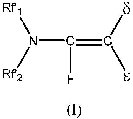
- where Rf'1 and Rf'2 are (i) independently linear or branched fluoroalkyl groups having 1-8, 1 - 6, or 1 - 4 carbon atoms and optionally include one or more catenated heteroatoms (e.g., O, N, or S); or (ii) bonded together to form a ring structure having 4 - 8 or 4 - 6 carbon atoms and optionally include one or more catenated heteroatoms (e.g., O, N, or S), and
- δ and ε are H or F,
- with the proviso that at least one of δ and ε is H.
- In some embodiments, δ is H and ε is F. In another embodiment, both of δ and ε are H. In some embodiments, at least one of Rf'1and Rf2 have two or more carbon atoms. In some embodiments, either or both of Rf'1 and Rf2 are perfluorinated.
- In some embodiments, the present disclosure is directed to hydrofluoroolefin compounds represented by the following general formula (II):

- In some embodiments, the present disclosure is directed to hydrofluoroolefin compounds represented by the following general formula (III):

- where Rf"'1 and Rf"'2 are (i) independently linear or branched fluoroalkyl groups having 1 - 8, 1 - 6, or 1 - 4 carbon atoms and optionally include one or more catenated heteroatoms (e.g., O, N, or S); or (ii) bonded together to form a ring structure having 4 - 8 or 4 - 6 carbon atoms and optionally include one or more catenated heteroatoms (e.g., O, N, or S), and
- the elements ζ, η, θ, λ, and µ may be H or F,
- with the proviso that at least one of ζ, η, θ, λ and µ is H.
- In some embodiments, ζ, η, and θ are F atoms, and λ and µ are H. In another embodiment ζ, η, and θ are F atoms, one of λ and µ is H, and the other of λ and µ is F. In yet another embodiment, ζ, η, and θ are H atoms, and λ and µ are F. In some embodiments, either or both of Rf'" 1 and Rf'"2 are perfluorinated.
- In some embodiments, any of the above discussed catentated heteroatoms may be secondary O heteroatoms wherein the O is bonded to two carbon atoms. In some embodiments, any of the above discussed catenated heteroatoms may be tertiary N heteroatoms wherein the N is bonded to three perfluorinated carbon atoms. In some embodiments, any of the above discussed catenated heteroatoms may be secondary S heteroatoms wherein the S is bonded to two perfluorinated carbon atoms, and the remaining valences on S, if present, are occupied by F.
- In some embodiments, the fluorine content in the hydrofluoroolefin compounds of the present disclosure may be sufficient to make the compounds non-flammable according to ASTM D-3278-96 e-1 test method ("Flash Point of Liquids by Small Scale Closed Cup Apparatus").
- In various embodiments, representative examples of the compounds of general formula (I) include the following:


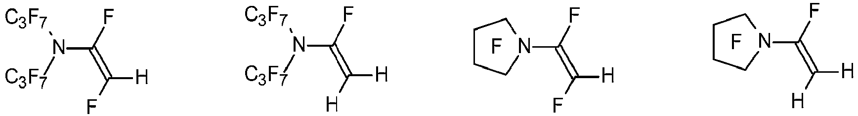

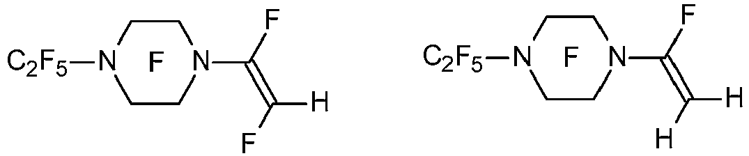
- In various embodiments, representative examples of the compounds of general formula (II) include the following:


- In various embodiments, representative examples of the compounds of general formula (III) include the following:


- For purposes of the present disclosure, it is to be appreciated that the hydrofluoroolefin compounds may include the E isomer, the Z isomer, or a mixture of the E and Z isomers, irrespective of what is depicted in any of the general formulas or chemical structures.
- In some embodiments, the hydrofluoroolefin compounds of the present disclosure may be hydrophobic, relatively chemically unreactive, and thermally stable. The hydrofluoroolefin compounds may have a low environmental impact. In this regard, the hydrofluoroolefin compounds of the present disclosure may have a global warming potential (GWP) of less than 500, 300, 200, 100 or even less than 10. As used herein, GWP is a relative measure of the global warming potential of a compound based on the structure of the compound. The GWP of a compound, as defined by the Intergovernmental Panel on Climate Change (IPCC) in 1990 and updated in 2007, is calculated as the warming due to the release of 1 kilogram of a compound relative to the warming due to the release of 1 kilogram of CO2 over a specified integration time horizon (ITH).

- In this equation ai is the radiative forcing per unit mass increase of a compound in the atmosphere (the change in the flux of radiation through the atmosphere due to the IR absorbance of that compound), C is the atmospheric concentration of a compound, τ is the atmospheric lifetime of a compound, t is time, and i is the compound of interest. The commonly accepted ITH is 100 years representing a compromise between short-term effects (20 years) and longer-term effects (500 years or longer). The concentration of an organic compound, i, in the atmosphere is assumed to follow pseudo first order kinetics (i.e., exponential decay). The concentration of CO2 over that same time interval incorporates a more complex model for the exchange and removal of CO2 from the atmosphere (the Bern carbon cycle model).
- In this equation ai is the radiative forcing per unit mass increase of a compound in the atmosphere (the change in the flux of radiation through the atmosphere due to the IR absorbance of that compound), C is the atmospheric concentration of a compound, τ is the atmospheric lifetime of a compound, t is time, and i is the compound of interest. The commonly accepted ITH is 100 years representing a compromise between short-term effects (20 years) and longer-term effects (500 years or longer). The concentration of an organic compound, i, in the atmosphere is assumed to follow pseudo first order kinetics (i.e., exponential decay). The concentration of CO2 over that same time interval incorporates a more complex model for the exchange and removal of CO2 from the atmosphere (the Bern carbon cycle model).
- In some embodiments, the hydrofluoroolefin compounds represented by general formula (I) can be prepared by reduction of a perfluorinated vinyl amine precursor with common hydride reducing agents, as illustrated in Scheme 1.

- Generally, the reaction of Scheme 1 can be controlled to selectively produce either the mono-hydride or the di-hydride (shown in Scheme 1) as the major product depending upon reaction conditions, stoichiometry, solvent system, and the hydride reducing agent chosen. The hydride reduction reaction shown in Scheme 1 can be effected by combining the perfluorinated vinyl amine starting compound with a hydride reducing agent in a solvent. Useful hydride reducing agents include, for example, NaBH4, LiBH4, (CH3)4NBH4, LiAlH4, NaAlH4, NaAlH2(OCH2CH2OCH3)2, LiAlH(OC(CH3)3)3, LiAlH(OCH3)3, NaBH3F, NaBH3CN, BH3, BH3-THF, B2H6, AlH3, AlH3-THF, ((CH3)2CHCH2)2AlH, and the like, and mixtures thereof. Solvents for this reaction may be aqueous or nonaqueous, protic or aprotic, and may include water, ethers, alcohols, and various other organic solvents, including mixtures thereof, that are sufficiently stable to the chosen hydride reducing agent. The reactants can be combined in a reactor (for example, a glass reactor or a metal pressure reactor) in any order, and the reaction can be run at a desired temperature (for example, from about -80°C to about 100°C) under the above described conditions with agitation. Generally, however, use of a non-reactive, polar organic solvent (for example, tetrahydrofuran, methyl-tetrahydrofuran, diethyl ether, methyl-t-butyl ether, cyclopentyl methyl ether, glyme, diglyme, triglyme, tetraglyme, i-propanol, or a mixture of two or more thereof) may be employed. The major product formed (mono-hydride or dihydride) is generally determined by the choice of hydride reducing agent and solvent and reaction conditions. A strong hydride reducing agent, protic solvents, high reaction temperatures and long reaction times typically favor the dihydride product, whereas a weak hydride reducing agent, aprotic solvents, low reaction temperatures, and short reaction times typically favor the monohydride product.
- In some embodiments, the perfluorinated vinyl amine starting compounds can be prepared by electrochemical perfluorination of the appropriate nitrogen containing hydrocarbon carboxylate derivatives followed by decarboxylation of the perfluorinated nitrogen-containing carboxylates using procedures that are known in the art, such as described in T. Abe, E. Hayashi, H. Baba, H. Fukaya, J. Fluorine Chem. 48 (1990) 257; T. Abe, E. Hayashi, H. Fukaya, H. Baba, J. Fluorine Chem. 50 (1990) 173; T. Abe, E. Hayashi, T. Shimizu, Chem. Lett. 1989, 905;
T. Abe, U.S. Patent 4,782,148 ; and T. Abe, E. Hayashi, Chem. Lett. 1988, 1887 Representative examples of perfluorinated vinyl amines useful as starting compounds for preparing the hydrofluoroolefin compounds represented by general formula (I) include, but are not limited to, the following structures: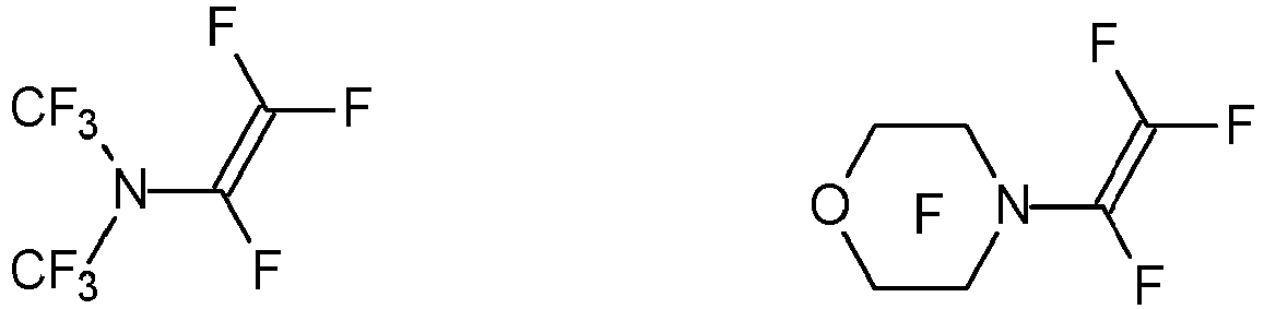

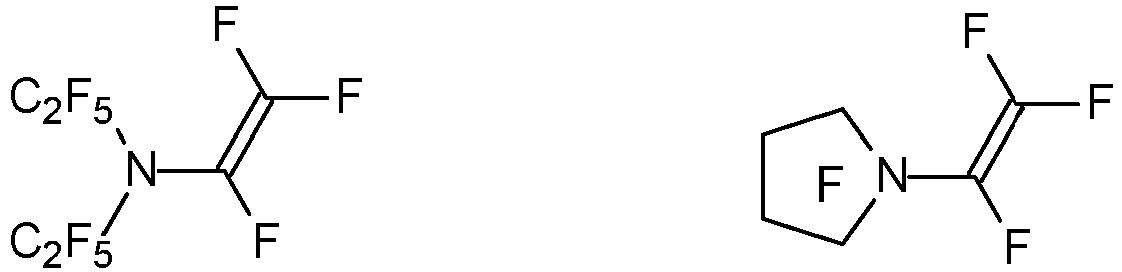

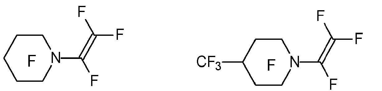

- In some embodiments, the hydrofluoroolefin compounds represented by general formula (II) can be prepared by reduction of a perfluorinated 1-propenyl amine precursor with common hydride reducing agents (as described above), as illustrated in Scheme 2.


JP 01070444A JP 0107445A - Representative examples of perfluorinated 1-propenyl amines useful as starting compounds for preparing the nitrogen-containing HFO compositions of general formula II include, but are not limited to,the following:
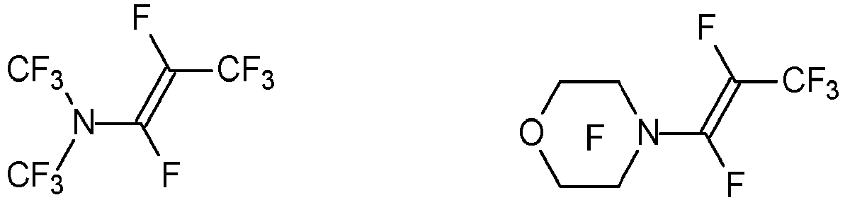


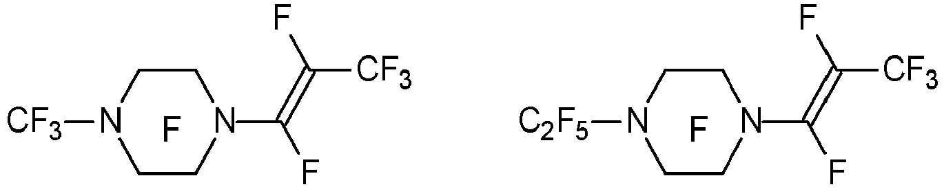
- In some embodiments, the hydrofluoroolefin compounds represented by general formula (III) can be prepared by reduction of a perfluorinated 2-propenyl amine precursor with common hydride reducing agents (described above), as illustrated in Scheme 3. Although up to 5 of the fluorine atoms (associated with the 2-propenyl group) of the 2-propenyl amine can in theory be replaced with hydrogen via the reaction shown in Scheme 3, only the major mono-hydride, di-hydride, and tri-hydride isomers are shown, for purposes of illustration.

- Generally, the degree of fluorine replacement by hydrogen in Scheme 3 can be controlled by choice of reaction conditions, stoichiometry, solvent, and the hydride reducing agent. The hydride reduction reaction shown in Scheme 3 can be effected using the same hydride reducing agents, the same solvents, and the same general processes and reaction conditions described for Scheme 1, except that the fluorinated starting compound (or precursor) is a perfluorinated 2-propenyl amine. The perfluorinated 2-propenyl amine starting compounds can be prepared by electrochemical perfluorination of the appropriate nitrogen containing hydrocarbon carboxylate derivatives followed by decarboxylation of the perfluorinated nitrogen-containing carboxylates using procedures that are known in the art, including those described by T. Abe,
JP 01070444A JP 01 07445A 


- Additionally, the hydrofluoroolefins of the present disclosure (general formulas I, II, and III) may be prepared by alternate methods that are known in the art, including reaction of the corresponding perfluorinated olefins (shown above) via a series of alternating catalytic hydrogenation (with H2) and dehydrofluorination steps. Such hydrogenation and dehydrofluorination steps can be conducted in a conventional batch reactor or in a continuous flow reactor in the presence of one or more catalysts known to be active for the hydrogenation of fluorinated olefins or the dehydrofluorination of hydrofluorocarbons. Such hydrogenation and dehydrofluorination catalysts and processes are well known in the art, and have been widely applied to fluorinated substrates, as described in
U.S. patents 7,560,602 ,5,986,151 ,5,396,000 ,6,369,284 , and8,530,708 . - In some embodiments, the present disclosure is further directed to working fluids that include the above-described hydrofluoroolefin compounds as a major component. For example, the working fluids may include at least 25%, at least 50%, at least 70%, at least 80%, at least 90%, at least 95%, or at least 99% by weight of the above-described hydrofluoroolefin compounds based on the total weight of the working fluid. In addition to the hydrofluoroolefin compounds, the working fluids may include a total of up to 75%, up to 50%, up to 30%, up to 20%, up to 10%, or up to 5% by weight of one or more of the following components: alcohols, ethers, alkanes, alkenes, haloalkenes, perfluorocarbons, perfluorinated tertiary amines, perfluoroethers, cycloalkanes, esters, ketones, oxiranes, aromatics, siloxanes, hydrochlorocarbons, hydrochlorofluorocarbons, hydrofluorocarbons, hydrofluoroolefins, hydrochloroolefins, hydrochlorofluoroolefins, hydrofluoroethers, or mixtures thereof, based on the total weight of the working fluid. Such additional components can be chosen to modify or enhance the properties of a composition for a particular use.
- In some embodiments, the present disclosure is further directed to an apparatus for heat transfer that includes a device and a mechanism for transferring heat to or from the device. The mechanism for transferring heat may include a heat transfer working fluid that includes a hydrofluoroolefin compounds of the present disclosure.
- The provided apparatus for heat transfer may include a device. The device may be a component, work-piece, assembly, etc. to be cooled, heated or maintained at a predetermined temperature or temperature range. Such devices include electrical components, mechanical components and optical components. Examples of devices of the present disclosure include, but are not limited to microprocessors, wafers used to manufacture semiconductor devices, power control semiconductors, electrical distribution switch gear, power transformers, circuit boards, multi-chip modules, packaged and unpackaged semiconductor devices, lasers, chemical reactors, fuel cells, and electrochemical cells. In some embodiments, the device can include a chiller, a heater, or a combination thereof.
- In yet other embodiments, the devices can include electronic devices, such as processors, including microprocessors. As these electronic devices become more powerful, the amount of heat generated per unit time increases. Therefore, the mechanism of heat transfer plays an important role in processor performance. The heat-transfer fluid typically has good heat transfer performance, good electrical compatibility (even if used in "indirect contact" applications such as those employing cold plates), as well as low toxicity, low (or non-) flammability and low environmental impact. Good electrical compatibility suggests that the heat-transfer fluid candidate exhibit high dielectric strength, high volume resistivity, and poor solvency for polar materials. Additionally, the heat-transfer fluid should exhibit good mechanical compatibility, that is, it should not affect typical materials of construction in an adverse manner.
- The provided apparatus may include a mechanism for transferring heat. The mechanism may include a heat transfer fluid. The heat transfer fluid may include one or more hydrofluoroolefin compounds of the present disclosure. Heat may be transferred by placing the heat transfer mechanism in thermal contact with the device. The heat transfer mechanism, when placed in thermal contact with the device, removes heat from the device or provides heat to the device, or maintains the device at a selected temperature or temperature range. The direction of heat flow (from device or to device) is determined by the relative temperature difference between the device and the heat transfer mechanism.
- The heat transfer mechanism may include facilities for managing the heat-transfer fluid, including, but not limited to pumps, valves, fluid containment systems, pressure control systems, condensers, heat exchangers, heat sources, heat sinks, refrigeration systems, active temperature control systems, and passive temperature control systems. Examples of suitable heat transfer mechanisms include, but are not limited to, temperature controlled wafer chucks in plasma enhanced chemical vapor deposition (PECVD) tools, temperature-controlled test heads for die performance testing, temperature-controlled work zones within semiconductor process equipment, thermal shock test bath liquid reservoirs, and constant temperature baths. In some systems, such as etchers, ashers, PECVD chambers, vapor phase soldering devices, and thermal shock testers, the upper desired operating temperature may be as high as 170°C, as high as 200°C, or even as high as 230°C.
- Heat can be transferred by placing the heat transfer mechanism in thermal contact with the device. The heat transfer mechanism, when placed in thermal contact with the device, removes heat from the device or provides heat to the device, or maintains the device at a selected temperature or temperature range. The direction of heat flow (from device or to device) is determined by the relative temperature difference between the device and the heat transfer mechanism. The provided apparatus can also include refrigeration systems, cooling systems, testing equipment and machining equipment. In some embodiments, the provided apparatus can be a constant temperature bath or a thermal shock test bath.
- In some embodiments, the present disclosure is directed to a fire extinguishing composition. The composition may include one or more hydrofluoroolefin compounds of the present disclosure and one or more co-extinguishing agents.
- In illustrative embodiments, the co-extinguishing agent may include hydrofluorocarbons, hydrochlorofluorocarbons, perfluorocarbons, perfluoropolyethers, hydrofluoroethers, hydrofluoropolyethers, chlorofluorocarbons, bromofluorocarbons, bromochlorofluorocarbons, hydrobromocarbons, iodofluorocarbons, fluorinated ketones, hydrofluorocarbons, hydrochlorofluorocarbons, perfluorocarbons, perfluoropolyethers, hydrofluoroethers, hydrofluoropolyethers, chlorofluorocarbons, bromofluorocarbons, bromochlorofluorocarbons, iodofluorocarbons, hydrobromofluorocarbons, fluorinated ketones, hydrobromocarbons, fluorinated olefins, hydrofluoroolefins, fluorinated sulfones, fluorinated vinylethers, unsaturated fluoro-ethers, bromofluoroolefins, chlorofluorolefins, iodofluoroolefins , fluorinated vinyl amines, fluorinated aminopropenes and mixtures thereof.
- Such co-extinguishing agents can be chosen to enhance the extinguishing capabilities or modify the physical properties (e.g., modify the rate of introduction by serving as a propellant) of an extinguishing composition for a particular type (or size or location) of fire and can preferably be utilized in ratios (of co-extinguishing agent to hydrofluoroolefin compound) such that the resulting composition does not form flammable mixtures in air.
- In some embodiments, the hydrofluoroolefin compounds and the co-extinguishing agent may be present in the fire extinguishing composition in amounts sufficient to suppress or extinguish a fire. The hydrofluoroolefin compounds and the co-extinguishing agent can be in a weight ratio of from about 9:1 to about 1:9.
- In some embodiments, the present disclosure is directed to an apparatus for converting thermal energy into mechanical energy in a Rankine cycle. The apparatus may include a working fluid that includes one or more hydrofluoroolefin compounds of the present disclosure. The apparatus may further include a heat source to vaporize the working fluid and form a vaporized working fluid, a turbine through which the vaporized working fluid is passed thereby converting thermal energy into mechanical energy, a condenser to cool the vaporized working fluid after it is passed through the turbine, and a pump to recirculate the working fluid.
- In some embodiments, the present disclosure relates to a process for converting thermal energy into mechanical energy in a Rankine cycle. The process may include using a heat source to vaporize a working fluid that includes one or more hydrofluoroolefin compounds of the present disclosure to form a vaporized working fluid. In some embodiments, the heat is transferred from the heat source to the working fluid in an evaporator or boiler. The vaporized working fluid may pressurized and can be used to do work by expansion. The heat source can be of any form such as from fossil fuels, e.g., oil, coal, or natural gas. Additionally, in some embodiments, the heat source can come from nuclear power, solar power, or fuel cells. In other embodiments, the heat can be "waste heat" from other heat transfer systems that would otherwise be lost to the atmosphere. The "waste heat," in some embodiments, can be heat that is recovered from a second Rankine cycle system from the condenser or other cooling device in the second Rankine cycle.
- An additional source of "waste heat" can be found at landfills where methane gas is flared off. In order to prevent methane gas from entering the environment and thus contributing to global warming, the methane gas generated by the landfills can be burned by way of "flares" producing carbon dioxide and water which are both less harmful to the environment in terms of global warming potential than methane. Other sources of "waste heat" that can be useful in the provided processes are geothermal sources and heat from other types of engines such as gas turbine engines that give off significant heat in their exhaust gases and to cooling liquids such as water and lubricants.
- In the provided process, the vaporized working fluid may expanded though a device that can convert the pressurized working fluid into mechanical energy. In some embodiments, the vaporized working fluid is expanded through a turbine which can cause a shaft to rotate from the pressure of the vaporized working fluid expanding. The turbine can then be used to do mechanical work such as, in some embodiments, operate a generator, thus generating electricity. In other embodiments, the turbine can be used to drive belts, wheels, gears, or other devices that can transfer mechanical work or energy for use in attached or linked devices.
- After the vaporized working fluid has been converted to mechanical energy the vaporized (and now expanded) working fluid can be condensed using a cooling source to liquefy for reuse. The heat released by the condenser can be used for other purposes including being recycled into the same or another Rankine cycle system, thus saving energy. Finally, the condensed working fluid can be pumped by way of a pump back into the boiler or evaporator for reuse in a closed system.
- The desired thermodynamic characteristics of organic Rankine cycle working fluids are well known to those of ordinary skill and are discussed, for example, in
U.S. Pat. Appl. Publ. No. 2010/0139274 (Zyhowski et al. ). The greater the difference between the temperature of the heat source and the temperature of the condensed liquid or a provided heat sink after condensation, the higher the Rankine cycle thermodynamic efficiency. The thermodynamic efficiency is influenced by matching the working fluid to the heat source temperature. The closer the evaporating temperature of the working fluid to the source temperature, the higher the efficiency of the system. Toluene can be used, for example, in the temperature range of 79°C to about 260°C, however toluene has toxicological and flammability concerns. Fluids such as 1,1-dichloro-2,2,2-trifluoroethane and 1,1,1,3,3-pentafluoropropane can be used in this temperature range as an alternative. But 1,1-dichloro-2,2,2-trifluoroethane can form toxic compounds below 300°C and need to be limited to an evaporating temperature of about 93°C to about 121°C. Thus, there is a desire for other environmentally-friendly Rankine cycle working fluids with higher critical temperatures so that source temperatures such as gas turbine and internal combustion engine exhaust can be better matched to the working fluid. - In some embodiments, the present disclosure relates to the use of the hydrofluoroolefin compounds of the present disclosure as nucleating agents in the production of polymeric foams and in particular in the production of polyurethane foams and phenolic foams. In this regard, in some embodiments, the present disclosure is directed to a foamable composition that includes one or more blowing agents, one or more foamable polymers or precursor compositions thereof, and one or more nucleating agents that include a hydrofluoroolefin compound of the present disclosure.
- In some embodiments, a variety of blowing agents may be used in the provided foamable compositions including liquid or gaseous blowing agents that are vaporized in order to foam the polymer or gaseous blowing agents that are generated in situ in order to foam the polymer. Illustrative examples of blowing agents include hydrochlorofluorocarbons (HCFCs), hydrofluorocarbons (HFCs), hydrochlorocarbons (HCCs), iodofluorocarbons (IFCs), hydrocarbons, hydrofluoroolefins (HFOs) and hydrofluoroethers (HFEs). The blowing agent for use in the provided foamable compositions can have a boiling point of from about -45°C to about 100°C at atmospheric pressure. Typically, at atmospheric pressure the blowing agent has a boiling point of at least about 15°C, more typically between about 20°C and about 80°C. The blowing agent can have a boiling point of between about 30°C and about 65°C. Further illustrative examples of blowing agents that can be used in the invention include aliphatic and cycloaliphatic hydrocarbons having about 5 to about 7 carbon atoms, such as n-pentane and cyclopentane, esters such as methyl formate, HFCs such as CF3CF2CHFCHFCF3, CF3CH2CF2H, CF3CH2CF2CH3, CF3CF2H, CH3CF2H (HFC-152a), CF3CH2CH2CF3 and CHF2CF2CH2F, HCFCs such as CH3CCl2F, CF3CHCl2, and CF2HC, HCCs such as 2-chloropropane, and IFCs such as CF3I, and HFEs such as C4F9OCH3 and HFOs such as CF3CF=CH2, CF3CH=CHF, CF3CH=CHCl and CF3CH=CHCF3 In certain formulations CO2 generated from the reaction of water with foam precursor such as an isocyanate can be used as a blowing agent.
- In various embodiments, the provided foamable composition may also include one or more foamable polymers or a precursor composition thereof. Foamable polymers suitable for use in the provided foamable compositions include, for example, polyolefins, e.g., polystyrene, poly(vinyl chloride), and polyethylene. Foams can be prepared from styrene polymers using conventional extrusion methods. The blowing agent composition can be injected into a heat-plastified styrene polymer stream within an extruder and admixed therewith prior to extrusion to form foam. Representative examples of suitable styrene polymers include, for example, the solid homopolymers of styrene, α-methylstyrene, ring-alkylated styrenes, and ring-halogenated styrenes, as well as copolymers of these monomers with minor amounts of other readily copolymerizable olefinic monomers, e.g., methyl methacrylate, acrylonitrile, maleic anhydride, citraconic anhydride, itaconic anhydride, acrylic acid, N-vinylcarbazole, butadiene, and divinylbenzene. Suitable vinyl chloride polymers include, for example, vinyl chloride homopolymer and copolymers of vinyl chloride with other vinyl monomers. Ethylene homopolymers and copolymers of ethylene with, e.g., 2-butene, acrylic acid, propylene, or butadiene may also be useful. Mixtures of different types of polymers can be employed.
- In various embodiments, the foamable compositions of the present disclosure may have a molar ratio of nucleating agent to blowing agent of no more than 1:50, 1:25, 1:9, or 1:7, 1:3, or 1:2.
- Other conventional components of foam formulations can, optionally, be present in the foamable compositions of the present disclosure. For example, cross-linking or chain-extending agents, foam-stabilizing agents or surfactants, catalysts and fire-retardants can be utilized. Other possible components include fillers (e.g., carbon black), colorants, fungicides, bactericides, antioxidants, reinforcing agents, antistatic agents, and other additives or processing aids.
- In some embodiments, polymeric foams can be prepared by vaporizing at least one liquid or gaseous blowing agent or generating at least one gaseous blowing agent in the presence of at least one foamable polymer or a precursor composition thereof and a nucleating agent as described above. In further embodiments, polymeric foams can be prepared using the provided foamable compositions by vaporizing (e.g., by utilizing the heat of precursor reaction) at least one blowing agent in the presence of a nucleating agent as described above, at least one organic polyisocyanate and at least one compound containing at least two reactive hydrogen atoms. In making a polyisocyanate-based foam, the polyisocyanate, reactive hydrogen-containing compound, and blowing agent composition can generally be combined, thoroughly mixed (using, e.g., any of the various known types of mixing head and spray apparatus), and permitted to expand and cure into a cellular polymer. It is often convenient, but not necessary, to preblend certain of the components of the foamable composition prior to reaction of the polyisocyanate and the reactive hydrogen-containing compound. For example, it is often useful to first blend the reactive hydrogen-containing compound, blowing agent composition, and any other components (e.g., surfactant) except the polyisocyanate, and to then combine the resulting mixture with the polyisocyanate. Alternatively, all components of the foamable composition can be introduced separately. It is also possible to pre-react all or a portion of the reactive hydrogen-containing compound with the polyisocyanate to form a prepolymer.
- In some embodiments, the present disclosure is directed to dielectric fluids that include one or more hydrofluoroolefin compounds of the present disclosure, as well as to electrical devices (e.g., capacitors, switchgear, transformers, or electric cables or buses) that include such dielectric fluids. For purposes of the present application, the term "dielectric fluid" is inclusive of both liquid dielectrics and gaseous dielectrics. The physical state of the fluid, gaseous or liquid, is determined at the operating conditions of temperature and pressure of the electrical device in which it is used.
- In some embodiments, the dielectric fluids include one or more hydrofluoroolefin compounds of the present disclosure and, optionally, one or more second dielectric fluids. Suitable second dielectric fluids include, for example, air, nitrogen, helium, argon, and carbon dioxide, or combinations thereof. The second dielectric fluid may be a non-condensable gas or an inert gas. Generally, the second dielectric fluid may be used in amounts such that vapor pressure is at least 70 kPa at 25°C, or at the operating temperature of the electrical device.
- The dielectric fluids of the present application are useful for electrical insulation and for arc quenching and current interruption equipment used in the transmission and distribution of electrical energy. Generally, there are three major types of electrical devices in which the fluids of the present disclosure can be used: (1) gas-insulated circuit breakers and current-interruption equipment, (2) gas-insulated transmission lines, and (3) gas-insulated transformers. Such gas-insulated equipment is a major component of power transmission and distribution systems.
- In some embodiments, the present disclosure provides electrical devices, such as capacitors, comprising metal electrodes spaced from each other such that the gaseous dielectric fills the space between the electrodes. The interior space of the electrical device may also comprise a reservoir of the liquid dielectric fluid which is in equilibrium with the gaseous dielectric fluid. Thus, the reservoir may replenish any losses of the dielectric fluid.
- In some embodiments, the present disclosure relates to coating compositions that include a solvent composition that one or more hydrofluoroolefin compounds of the present disclosure, and one or more coating materials which are soluble or dispersible in the solvent composition.
- In various embodiments, the coating materials of the coating compositions may include pigments, lubricants, stabilizers, adhesives, anti-oxidants, dyes, polymers, pharmaceuticals, release agents, inorganic oxides, and the like, and combinations thereof. For example, coating materials may include perfluoropolyether, hydrocarbon, and silicone lubricants; amorphous copolymers of tetrafluoroethylene; polytetrafluoroethylene; or combinations thereof. Further examples of suitable coating materials include titanium dioxide, iron oxides, magnesium oxide, perfluoropolyethers, polysiloxanes, stearic acid, acrylic adhesives, polytetrafluoroethylene, amorphous copolymers of tetrafluoroethylene, or combinations thereof.
- In some embodiments, the above-described coating compositions can be useful in coating deposition, where the hydrofluoroolefin compounds function as a carrier for a coating material to enable deposition of the material on the surface of a substrate. In this regard, the present disclosure further relates to a process for depositing a coating on a substrate surface using the coating composition. The process comprises the step of applying to at least a portion of at least one surface of a substrate a coating of a liquid coating composition comprising (a) a solvent composition containing one or more of the hydrofluoroolefin compounds; and (b) one or more coating materials which are soluble or dispersible in the solvent composition. The solvent composition can further comprise one or more co-dispersants or co-solvents and/or one or more additives (e.g., surfactants, coloring agents, stabilizers, anti-oxidants, flame retardants, and the like). Preferably, the process further comprises the step of removing the solvent composition from the coating by, e.g., allowing evaporation (which can be aided by the application of, e.g., heat or vacuum).
- In various embodiments, to form a coating composition, the components of the coating composition (i.e., the hydrofluoroolefin compound(s), the coating material(s), and any co-dispersant(s) or co-solvent(s) utilized) can be combined by any conventional mixing technique used for dissolving, dispersing, or emulsifying coating materials, e.g., by mechanical agitation, ultrasonic agitation, manual agitation, and the like. The solvent composition and the coating material(s) can be combined in any ratio depending upon the desired thickness of the coating. For example, the coating material(s) may constitute from about 0.1 to about 10 weight percent of the coating composition.
- In illustrative embodiments, the deposition process of the disclosure can be carried out by applying the coating composition to a substrate by any conventional technique. For example, the composition can be brushed or sprayed (e.g., as an aerosol) onto the substrate, or the substrate can be spin-coated. In some embodiments, the substrate may be coated by immersion in the composition. Immersion can be carried out at any suitable temperature and can be maintained for any convenient length of time. If the substrate is a tubing, such as a catheter, and it is desired to ensure that the composition coats the lumen wall, the composition may be drawn into the lumen by the application of reduced pressure.
- In various embodiments, after a coating is applied to a substrate, the solvent composition can be removed from the coating (e.g., by evaporation). If desired, the rate of evaporation can be accelerated by application of reduced pressure or mild heat. The coating can be of any convenient thickness, and, in practice, the thickness will be determined by such factors as the viscosity of the coating material, the temperature at which the coating is applied, and the rate of withdrawal (if immersion is utilized).
- Both organic and inorganic substrates can be coated by the processes of the present disclosure. Representative examples of the substrates include metals, ceramics, glass, polycarbonate, polystyrene, acrylonitrile-butadiene-styrene copolymer, natural fibers (and fabrics derived therefrom) such as cotton, silk, fur, suede, leather, linen, and wool, synthetic fibers (and fabrics) such as polyester, rayon, acrylics, nylon, or blends thereof, fabrics including a blend of natural and synthetic fibers, and composites of the foregoing materials. In some embodiments, substrates that may be coated include, for example, magnetic hard disks or electrical connectors with perfluoropolyether lubricants or medical devices with silicone lubricants.
- In some embodiments, the present disclosure relates to cleaning compositions that include one or more hydrofluoroolefin compounds of the present disclosure, and one or more co-solvents.
- In some embodiments, the hydrofluoroolefin compounds may be present in an amount greater than 50 weight percent, greater than 60 weight percent, greater than 70 weight percent, or greater than 80 weight percent based upon the total weight of the hydrofluoroolefin compounds and the co-solvent(s).
- In various embodiments, the cleaning composition may further comprise a surfactant. Suitable surfactants include those surfactants that are sufficiently soluble in the fluorinated olefin, and which promote soil removal by dissolving, dispersing or displacing the soil. One useful class of surfactants are those nonionic surfactants that have a hydrophilic-lipophilic balance (HLB) value of less than about 14. Examples include ethoxylated alcohols, ethoxylatedalkyl phenols, ethoxylated fatty acids, alkylarysulfonates, glycerol esters, ethoxylated fluoroalcohols, and fluorinated sulfonamides. Mixtures of surfactants having complementary properties may be used in which one surfactant is added to the cleaning composition to promote oily soil removal and another added to promote water-soluble oil removal. The surfactant, if used, can be added in an amount sufficient to promote soil removal. Typically, surfactant is added in amounts from about 0.1 to 5.0 wt. %, preferably in amounts from about 0.2 to 2.0 wt. % of the cleaning composition.
- In illustrative embodiments, the co-solvent may include alcohols, ethers, alkanes, alkenes, haloalkenes, perfluorocarbons, perfluorinated tertiary amines, perfluoroethers, cycloalkanes, esters, ketones, oxiranes, aromatics, haloaromatics, siloxanes, hydrochlorocarbons, hydrochlorofluorocarbons, hydrofluorocarbons, hydrofluoroolefins, hydrochloroolefins, hydrochlorofluoroolefins, hydrofluoroethers, or mixtures thereof. Representative examples of co-solvents which can be used in the cleaning composition include methanol, ethanol, isopropanol, t-butyl alcohol, methyl t-butyl ether, methyl t-amyl ether, 1,2-dimethoxyethane, cyclohexane, 2,2,4-trimethylpentane, n-decane, terpenes (e.g., a-pinene, camphene, and limonene), trans-1,2-dichloroethylene, cis-1,2-dichloroethylene, methylcyclopentane, decalin, methyl decanoate, t-butyl acetate, ethyl acetate, diethyl phthalate, 2-butanone, methyl isobutyl ketone, naphthalene, toluene, p-chlorobenzotrifluoride, trifluorotoluene, bis(trifluoromethyl)benzenes, hexamethyl disiloxane, octamethyl trisiloxane, perfluorohexane, perfluoroheptane, perfluorooctane, perfluorotributylamine, perfluoro-N-methyl morpholine, perfluoro-2-butyl oxacyclopentane, methylene chloride, chlorocyclohexane, 1-chlorobutane, 1,1-dichloro-1-fluoroethane, 1,1,1-trifluoro-2,2-dichloroethane, 1,1,1,2,2-pentafluoro-3,3-dichloropropane, 1,1,2,2,3-pentafluoro-1,3-dichloropropane, 2,3-dihydroperfluoropentane, 1,1,1,2,2,4-hexafluorobutane, 1-trifluoromethyl-1,2,2-trifluorocyclobutane, 3-methyl-1,1,2,2-tetrafluorocyclobutane, 1-hydropentadecafluoroheptane, or mixtures thereof.
- In some embodiments, the present disclosure relates to a process for cleaning a substrate. The cleaning process can be carried out by contacting a contaminated substrate with a cleaning composition as discussed above. The hydrofluoroolefin compounds can be utilized alone or in admixture with each other or with other commonly-used cleaning solvents, e.g., alcohols, ethers, alkanes, alkenes, haloalkenes, perfluorocarbons, perfluorinated tertiary amines, perfluoroethers, cycloalkanes, esters, ketones, oxiranes, aromatics, haloaromatics, siloxanes, hydrochlorocarbons, hydrochlorofluorocarbons, hydrofluorocarbons, hydrofluoroolefins, hydrochloroolefins, hydrochlorofluoroolefins, hydrofluoroethers, or mixtures thereof. Such co-solvents can be chosen to modify or enhance the solvency properties of a cleaning composition for a particular use and can be utilized in ratios (of co-solvent to hydrofluoroolefin compounds) such that the resulting composition has no flash point. If desirable for a particular application, the cleaning composition can further contain one or more dissolved or dispersed gaseous, liquid, or solid additives (for example, carbon dioxide gas, surfactants, stabilizers, antioxidants, or activated carbon).
- In some embodiments, the present disclosure relates to cleaning compositions that include one or more hydrofluoroolefin compounds of the present disclosure and optionally one or more surfactants. Suitable surfactants include those surfactants that are sufficiently soluble in the hydrofluoroolefin compounds, and which promote soil removal by dissolving, dispersing or displacing the soil. One useful class of surfactants are those nonionic surfactants that have a hydrophilic-lipophilic balance (HLB) value of less than about 14. Examples include ethoxylated alcohols, ethoxylated alkylphenols, ethoxylated fatty acids, alkylaryl sulfonates, glycerol esters, ethoxylated fluoroalcohols, and fluorinated sulfonamides. Mixtures of surfactants having complementary properties may be used in which one surfactant is added to the cleaning composition to promote oily soil removal and another added to promote water-soluble soil removal. The surfactant, if used, can be added in an amount sufficient to promote soil removal. Typically, surfactant may be added in amounts from 0.1 to 5.0 wt. % or from 0.2 to 2.0 wt. % of the cleaning composition.
- The cleaning processes of the disclosure can also be used to dissolve or remove most contaminants from the surface of a substrate. For example, materials such as light hydrocarbon contaminants; higher molecular weight hydrocarbon contaminants such as mineral oils and greases; fluorocarbon contaminants such as perfluoropolyethers, bromotrifluoroethylene oligomers (gyroscope fluids), and chlorotrifluoroethylene oligomers (hydraulic fluids, lubricants); silicone oils and greases; solder fluxes; particulates; water; and other contaminants encountered in precision, electronic, metal, and medical device cleaning can be removed.
- The cleaning compositions can be used in either the gaseous or the liquid state (or both), and any of known or future techniques for "contacting" a substrate can be utilized. For example, a liquid cleaning composition can be sprayed or brushed onto the substrate, a gaseous cleaning composition can be blown across the substrate, or the substrate can be immersed in either a gaseous or a liquid composition. Elevated temperatures, ultrasonic energy, and/or agitation can be used to facilitate the cleaning. Various different solvent cleaning techniques are described by B. N. Ellis in Cleaning and Contamination of Electronics Components and Assemblies, Electrochemical Publications Limited, Ayr, Scotland, pages 182-94 (1986).
- Both organic and inorganic substrates can be cleaned by the processes of the present disclosure. Representative examples of the substrates include metals; ceramics; glass; polycarbonate; polystyrene; acrylonitrile-butadiene-styrene copolymer; natural fibers (and fabrics derived therefrom) such as cotton, silk, fur, suede, leather, linen, and wool; synthetic fibers (and fabrics) such as polyester, rayon, acrylics, nylon, or blends thereof; fabrics comprising a blend of natural and synthetic fibers; and composites of the foregoing materials. In some embodiments, the process may be used in the precision cleaning of electronic components (e.g., circuit boards), optical or magnetic media, or medical devices.
- In some embodiments, the present disclosure further relates to electrolyte compositions that include one or more hydrofluoroolefin compounds of the present disclosure. The electrolyte compositions may comprise (a) a solvent composition including one or more of the hydrofluoroolefin compounds; and (b) at least one electrolyte salt. The electrolyte compositions of the present disclosure exhibit excellent oxidative stability, and when used in high voltage electrochemical cells (such as rechargeable lithium ion batteries) provide outstanding cycle life and calendar life. For example, when such electrolyte compositions are used in an electrochemical cell with a graphitized carbon electrode, the electrolytes provide stable cycling to a maximum charge voltage of at least 4.5V and up to 6.0V vs. Li/Li+.
- Electrolyte salts that are suitable for use in preparing the electrolyte compositions of the present disclosure include those salts that comprise at least one cation and at least one weakly coordinating anion (the conjugate acid of the anion having an acidity greater than or equal to that of a hydrocarbon sulfonic acid (for example, a bis(perfluoroalkanesulfonyl)imide anion); that are at least partially soluble in a selected hydrofluoroolefin compound (or in a blend thereof with one or more other hydrofluoroolefin compounds or one or more conventional electrolyte solvents); and that at least partially dissociate to form a conductive electrolyte composition. The salts may be stable over a range of operating voltages, are non-corrosive, and are thermally and hydrolytically stable. Suitable cations include alkali metal, alkaline earth metal, Group IIB metal, Group IIIB metal, transition metal, rare earth metal, and ammonium (for example, tetraalkylammonium
or trialkylammonium) cations, as well as a proton. In some embodiments, cations for battery use include alkali metal and alkaline earth metal cations. Suitable anions include fluorine-containing inorganic anions such as (FSO2)2N-, BF4 -, PF6 -, AsF6 -, and SbF6 -; CIO4 -; HSO4 -; H2PO4 -; organic anions such as alkane, aryl, and alkaryl sulfonates; fluorine-containing and nonfluorinated tetraarylborates; carboranes and halogen-, alkyl-, or haloalkylsubstituted carborane anions including metallocarborane anions; and fluorine-containing organic anions such as perfluoroalkanesulfonates, cyanoperfluoroalkanesulfonylamides, bis(cyano)perfluoroalkanesulfonylmethides, bis(perfluoroalkanesulfonyl)imides, bis(perfluoroalkanesulfonyl)methides, and tris(perfluoroalkanesulfonyl)methides; and the like. Preferred anions for battery use include fluorine-containing inorganic anions (for example, (FSO2)2N-, BF4 -, PF6 -, and AsF6 -) and fluorine-containing organic anions (for example, perfluoroalkanesulfonates, bis(perfluoroalkanesulfonyl)imides, and tris(perfluoroalkanesulfonyl)methides). The fluorine-containing organic anions can be either fully fluorinated, that is perfluorinated, or partially fluorinated (within the organic portion thereof). In some embodiments, the fluorine-containing organic anion is at least about 80 percent fluorinated (that is, at least about 80 percent of the carbon-bonded substituents of the anion are fluorine atoms). In some embodiments, the anion is perfluorinated (that is, fully fluorinated, where all of the carbon-bonded substituents are fluorine atoms). The anions, including the perfluorinated anions, can contain one or more catenary heteroatoms such as, for example, nitrogen, oxygen, or sulfur. In some embodiments, fluorine-containing organic anions include perfluoroalkanesulfonates, bis(perfluoroalkanesulfonyl)imides, and tris(perfluoroalkanesulfonyl)methides. - In some embodiments, the electrolyte salts may include lithium salts. Suitable lithium salts include, for example, lithium hexafluorophosphate, lithium bis(trifluoromethanesulfonyl)imide, lithium bis(perfluoroethanesulfonyl)imide, lithium tetrafluoroborate, lithium perchlorate, lithium hexafluoroarsenate, lithium trifluoromethanesulfonate, lithium tris(trifluoromethanesulfonyl)methide, lithium bis(fluorosulfonyl)imide (Li-FSI), and mixtures of two or more thereof.
- The electrolyte compositions of the present disclosure can be prepared by combining at least one electrolyte salt and a solvent composition including at least one hydrofluoroolefin compound of the present disclosure, such that the salt is at least partially dissolved in the solvent composition at the desired operating temperature. The hydrofluoroolefin compounds (or a normally liquid composition including, consisting, or consisting essentially thereof) can be used in such preparation.
- In some embodiments, the electrolyte salt is employed in the electrolyte composition at a concentration such that the conductivity of the electrolyte composition is at or near its maximum value (typically, for example, at a Li molar concentration of around 0.1 - 4.0 M, or 1. 0 - 2.0 M, for electrolytes for lithium batteries), although a wide range of other concentrations may also be employed.
- In some embodiments, one or more conventional electrolyte solvents are mixed with the hydrofluoroolefin compound(s) (for example, such that the hydrofluoroolefin(s) constitute from about 1 to about 80 or 90 percent of the resulting solvent composition). Useful conventional electrolyte solvents include, for example, organic and fluorine-containing electrolyte solvents (for example, propylene carbonate, ethylene carbonate, dimethyl carbonate, diethyl carbonate, ethyl methyl carbonate, dimethoxyethane, 7-butyrolactone, diglyme (that is, diethylene glycol dimethyl ether), tetraglyme (that is, tetraethylene glycol dimethyl ether), monofluoroethylene carbonate, vinylene carbonate, ethyl acetate, methyl butyrate, tetrahydrofuran, alkyl-substituted tetrahydrofuran, 1, 3-dioxolane, alkyl-substituted 1, 3-dioxolane, tetrahydropyran, alkyl-substituted tetrahydropyran, and the like, and mixtures thereof). Other conventional electrolyte additives (for example, a surfactant) can also be present, if desired.
- The present disclosure further relates to electrochemical cells (e.g., fuel cells, batteries, capacitors, electrochromic windows) that include the above-described electrolyte compositions. Such an electrochemical cell may include a positive electrode, a negative electrode, a separator, and the above-described electrolyte composition.
- A variety of negative and positive electrodes may be employed in the electrochemical cells. Representative negative electrodes include graphitic carbons e. g. , those having a spacing between (002) crystallographic planes, d002, of 3.45 A > d002 > 3.354 A and existing in forms such as powders, flakes, fibers or spheres (e. g. , mesocarbon microbeads); Li4/3Ti5/304 the lithium alloy compositions described in
U. S. Pat. No. 6, 203, 944 (Turner '944) entitled "ELECTRODE FOR A LITHIUM BATTERY" andPCT Published Patent Application No. WO 00103444 - The electrochemical devices of the invention can be used in various electronic articles such as computers, power tools, automobiles, telecommunication devices, and the like.
- The operation of the present disclosure will be further described with regard to the following detailed examples. These examples are offered to further illustrate various embodiments and techniques. It should be understood, however, that many variations and modifications may be made while remaining within the scope of the present disclosure.
-
Liste of Materials: Name Description Source Sodium Borohydride NaBH4 Aldrich, USA Diglyme (Anhydrous) CH3OCH2CH2OCH2CH2OCH3 Aldrich, USA Phosphoric Acid H3PO4 Aldrich, USA Sodium Fluoride Powder NaF Mallinckrodt, USA Acetone CH3COCH3 EMD Millipore, USA Tributylamine (n-C4H9)3N Aldrich, USA Magnesium sulfate MgSO4 EMD Millipore, USA Tetraglyme CH3O(CH2CH2O)4CH3 Aldrich, USA 2-Propanol CH3CHOHCH3 Aldrich, USA Methanol CH3OH JT Baker, USA Sulfuric acid H2SO4 Aldrich, USA Novec 7100 C4F9OCH3 3M Co., USA Titanium(IV) chloride TiCl4 Alfa Aesar, USA Zinc Dust Zn Aldrich, USA - In these Examples, Log KOWs, (octanol/water partition coefficients), were determined by HPLC using the method described in OECD Method 117. Atmospheric lifetimes were experimentally determined using a relative rate method to determine the hydroxyl radical rate constant.
-

- Sodium borohydride (6.560g, 0.1734mol) was charged to a 1.0 L, 3-necked flask equipped with magnetic stirrer, ice bath, thermocouple probe, addition funnel, and a water cooled condenser equipped with a nitrogen inlet. Anhydrous diglyme solvent (188mL) was then batch charged to the reactor flask. After the reaction mixture was chilled to near 0°C, the perfluorinated propenyl amine, (C2F5)(CF3)N-CF=CFCF3 (110,00g, 0.3303mol), was charged to the addition funnel and added dropwise with stirring to the reaction mixture while maintaining cooling in ice bath. The dropwise addition was conducted over a 2.4hr period such that the reaction temperature never exceeded 8°C. Once all the perfluorinated propenyl amine starting material was added, the reaction was allowed to proceed for an additional 2 hours with stirring near 0°C. Then, the reaction mixture was quenched by the gradual addition of deionized water (363mL, added dropwise initially) with stirring between 0-12°C. Once water addition was complete, 34.4 wt% H3PO4(aq) (52.8g) was added dropwise (to minimize exotherm and foaming) with stirring between 0-6°C to adjust the pH of the reaction solution and destroy residual borohydride reagent. Once all the H3PO4(aq) was added, the reaction mixture was stirred for an additional 10 minutes at 0-5°C and then allowed to gradually warm to room temperature with stirring. Once stirring was stopped (at room temperature), the dense fluorinated product phase separated from the upper aqueous diglyme solution as a clear lower liquid phase. This two-phase mixture was transferred to a 1.0L separatory funnel to allow separation and isolation of the lower product phase. The crude fluorinated product was then washed with three 500mL portions of DI water, using some concentrated NaCl brine to break the emulsion formed during each wash step. Then the water-washed lower liquid phase was drained to a 250mL Erlenmeyer flask giving 74.4g (71.5% of theory) of crude product. GC and GC-MS analysis of this material revealed that it contained 96% (C2F5)(CF3)N-CF=CHCF3 (MW = 315) as a mixture of E and Z isomers. This material was dried over activated 3A molecular sieves (10g) and treated with a small amount of powdered NaF (1.0g) as well (to remove possible residual HF), in preparation for purification by fractional distillation.
- Two lots of crude product (totaling 108.1 grams) prepared essentially as described above were combined, filtered to remove molecular sieves and NaF and transferred to a 100mL 2-necked round bottomed flask. To the filtrate was added 3.8g of fresh NaF powder plus a magnetic stir bar and this mixture was then fractionally distilled with stirring at atmospheric pressure under a nitrogen atmosphere using a 40-plate concentric tube distillation column equipped with a liquid splitter distillation head and a condenser chilled to -10°C. The desired product was collected at a head temperature of 64.8-65.8°C (B.P.) yielding a total of 79.2g of (C2F5)(CF3)N-CF=CHCF3 (mixture of E and Z isomers) with an overall GC purity of 98%. The distilled product was a clear, non-viscous, colorless liquid. This material was further analyzed by quantitative 1H and 19F NMR spectroscopy revealing that it comprised 76.4 absolute wt% E-(C2F5)(CF3)N-CF=CHCF3 and 21.2 absolute wt% Z-(C2F5)(CF3)N-CF=CHCF3 (97.6 absolute wt% purity overall). The major impurities were identified as Z-(C2F5)(CF3)N-CH=CHCF3 (MW = 297) and two other isomers (totaling 1.13 absolute wt%). The density of the fractionally distilled product was determined to be 1.61 g/mL at 20°C (Anton Paar DMA 5000M density meter) and the specific heat capacity was 27.97 Joules/g°C (by DSC). The product mixture had an average Log KOW (octanol/water partition coefficient measured by HPLC) of 4.57.
-

- Sodium borohydride (10.69g, 0.2825mol) was charged to a 1.0 L, 3-necked flask equipped with overhead stirring, ice bath, thermocouple probe, addition funnel, and a water cooled condenser equipped with a nitrogen inlet. Anhydrous diglyme solvent (320mL) was then batch charged to the reactor flask. After the reaction mixture was chilled to near 0°C, the perfluorinated propenyl amine, O(CZF4)2N-CF=CFCF3 (200.00g, 0.5539mol), was charged to the addition funnel and added dropwise with stirring to the reaction mixture while maintaining cooling in ice bath. The dropwise addition was conducted over a 4hr period such that the reaction temperature never exceeded 8.1°C. Once all of the perfluorinated propenyl amine starting material was added, the reaction was allowed to proceed for an additional 15 minutes with stirring near 0°C. Then, the reaction mixture was quenched by the gradual addition of deionized water (350mL, added dropwise initially) with stirring between 0-12°C. Once water addition was complete, 34.4 wt% H3PO4(aq) (68.9g) was added dropwise (to minimize exotherm and foaming) with stirring between 0-6°C to adjust the pH of the reaction solution and destroy residual borohydride reagent. The stirring was stopped, and the reaction mixture was transferred to a 1.0L separatory funnel while still cold to allow separation and isolation of the dense fluorinated product phase. The crude fluorinated product was then washed with three 350mL portions of DI water. The water-washed lower liquid phase was drained to a 250mL Erlenmeyer flask giving 158.5g (83.4% of theory) of crude product. GC and GC-MS analysis of this material revealed that it contained 86% O(C2F4)2N-CF=CHCF3 (MW = 343) as a mixture of E and Z isomers. This material was dried over activated 3A molecular sieves (6.2g) and treated with a small amount of powdered NaF (4.0g) as well (to remove possible residual HF), in preparation for purification by fractional distillation. After drying, the material was filtered through a 10 micron polyethylene disposable fritted filter to remove molecular sieves and NaF, then transferred to a 100mL 3-necked round bottom flask. An additional 6.4g of fresh NaF powder plus a magnetic stir bar were charged to the flask and the material was fractionally distilled with stirring at atmospheric pressure under a nitrogen atmosphere using a 40-plate concentric tube distillation column equipped with a liquid splitter distillation head and a water cooled condenser.
- The desired product was collected at a head temperature of 93.1-99.2°C (B.P.) over 13 cuts. No cuts were greater than 95.3% pure, so the fractions were recombined and azeotropically distilled from >10x molar excess of acetone in an attempt to better isolate the desired mono-hydride product from trace perfluorinated starting material and dihydride impurities. The collected acetone/product distillate was water washed to remove acetone yielding 80.22g crude desired product. The crude product was treated with MgSO4 overnight to remove trace water. The mixture was filtered to remove MgSO4 and charged to a 100mL 3 neck RB flask where it was combined with tributylamine (20.0g, 0.108mol) and fractionally distilled one final time yielding a total of 56.5g of O(C2F4)2N-CF=CHCF3 (mixture of E and Z isomers) with an overall GC purity of 97.4% in the heart cuts (B.P = 94.8-95.5°C). The distilled product was a clear, non-viscous, colorless liquid. The purest cut (30.30 g, 97.81% pure) contained trace amounts of tributylamine. This cut was washed with 1.023N HCl(aq) (10.0g) to remove the amine impurity. Acid washed material was washed twice with water then dried over molecular sieves before being submitted for GC-MS, NMR, and COA under request M14-2499. The isolated desired product was verified to be a 97.1% pure mixture of E and Z isomers by NMR. The product mixture had an average Log KOW (octanol/water partition coefficient measured by HPLC) of 4.80. A toxicity screening study in rats indicated that the 4 Hr Inhalation LC50 of this compound was > 10,390 ppm. An atmospheric lifetime of 0.89 years was measured for this compound.
-

- Anhydrous diglyme solvent (200mL) was batch charged to a 1.0 L, 3-necked flask equipped with a mechanical stirrer, ice bath, thermocouple probe, addition funnel, Claisen adapter, and a chiller-cooled condenser equipped with a nitrogen inlet. The diglyme in the flask was chilled to 0°C using an ice bath and the condenser was chilled to -20°C. Then, sodium borohydride powder (13.021g, 0.3442mol) was batch charged to the cold diglyme with stirring to give a fluid suspension. While holding the reaction mixture near 0°C in ice bath, the perfluorinated propenyl amine, (CF3)2N-CF=CFCF3 (185.50g, 0.6554mol), was charged to the addition funnel and then added dropwise with stirring to the cold reaction mixture. The dropwise addition was conducted over a 5.2hr period such that the reaction temperature never exceeded 8°C. Once all the perfluorinated propenyl amine starting material was added, the reaction was allowed to proceed for an additional 2.5 hours with stirring near 0°C. Then, the reaction mixture was quenched by the gradual addition of deionized water (385mL, added dropwise initially) with stirring between 0-7°C. Once water addition was complete, 34.4 wt% H3PO4(aq) (115.24g) was added dropwise (to minimize exotherm and foaming) with stirring between 0-5°C to adjust the pH of the reaction solution and destroy residual borohydride reagent. Once all the H3PO4(aq) was added, the reaction mixture was stirred for an additional 30 minutes at 0-5°C and then allowed to gradually warm to room temperature overnight with stirring. Once stirring was stopped (at room temperature), a dense fluorinated product phase separated from the upper aqueous diglyme solution as a clear lower liquid phase. This two-phase mixture was chilled again to 0°C and then transferred to a 1.0L separatory funnel to allow separation and isolation of the lower fluorinated product phase. The crude fluorinated product was then washed with three 475mL portions of cold DI water, using some concentrated NaCl brine to break the emulsion formed during each water-wash step. After the final water wash, the lower liquid fluorochemical phase was drained to a 125mL HDPE polybottle, giving 117.5g (67.6% of theory) of crude product. GC and GC-MS analysis of this material revealed that it contained 92.1% (CF3)2N-CF=CHCF3 (MW = 265) as a mixture of E and Z isomers. In preparation for purification by fractional distillation, this material was dried over activated 3A molecular sieves (7g) for 1 week and then filtered and treated with powdered NaF (5.2g) for another week to remove possible residual HF.
- After a final filtration, the crude fluorinated product (103.9g) was combined with excess acetone (114.0g) and fresh NaF powder (2.3g) in a 250mL, 3-necked, round bottomed flask and this mixture was then fractionally distilled with magnetic stirring at atmospheric pressure under a nitrogen atmosphere using a 40-plate concentric tube distillation column equipped with a liquid splitter distillation head and a condenser chilled to -20°C. The desired product distilled as an azeotrope with acetone and the highest purity fractions (fractions 3 and 4) were collected at a head temperature of 43.1-45.6°C yielding a total of 76.9g of (CF3)2N-CF=CHCF3 (mixture of E and Z isomers) plus acetone. The distilled product/acetone mixtures collected in distillate fractions 3 and 4 were combined, transferred to a 250mL separatory funnel, and washed with three 200mL portions of cold deionized water to remove residual acetone. Addition of some concentrated NaCl brine was necessary during each water-wash step to break the emulsion that formed. Analysis of the final water washed product by GC-FID indicated that virtually all the acetone had been removed and the final product was 99.4% pure (E&Z)-(CF3)2N-CF=CHCF3. This material was dried over MgSO4 (2.0g) for a few days and then filtered through a 0.2 micron PVDF syringe filter to yield 59.0g of high purity product as a clear, non-viscous, colorless liquid. This material was further analyzed by GC-MS and quantitative one-dimensional and two-dimensional 1H and 19F NMR spectroscopy revealing that it comprised 76.0 absolute wt% (E)-(CF3)2N-CF=CHCF3 (MW=265) and 22.7 absolute wt% (Z)-(CF3)2N-CF=CHCF3 (MW=265), corresponding to 98.7 absolute wt% purity overall of desired product. The major impurities identified included 0.31 absolute wt% (E)-(CF3)2N-CH=CHCF3 (MW = 247), 0.45 absolute wt% (Z)-(CF3)2N-CH=CFCF3 (MW = 265), and 0.14 absolute wt% (E)-(CF3)2N-CH=CFCF3 (MW = 265). The density of the fractionally distilled product was determined to be 1.54 g/mL at 20°C (Anton Paar DMA 5000M density meter). The product mixture had an average Log KOW (octanol/water partition coefficient measured by HPLC) of 4.12. An atmospheric lifetime of 1.3 years was measured for this compound.
-

- In a jacketed 1000mL, 3-necked, round bottom flask equipped with overhead stirring, cold water condenser, dry nitrogen bubbler and an addition funnel, sodium borohydride (10.4 g, 0.265 mol) and diglyme (180g) were combined. The mixture was cooled using a setpoint on the chiller of -10°C to bring down the solution temperature to about 0°C. Then 2,2,3,3,5,5,6,6-octafluoro-4-(1,2,2-trifluorovinyl)morpholine (165 g , 0.530 mol) was added dropwise to the reaction mixture while adjusting the chiller temperature lower to keep the reaction temperature inside the flask at around 0°C. After the addition of the 2,2,3,3,5,5,6,6-octafluoro-4-(1,2,2-trifluorovinyl)morpholine was complete the reaction was stirred for 30 minutes and then quenched with water. After quenching with water, 35% (w/w) phosphoric acid was added to adjust the pH to approximately 3 and dissolve any solids. The lower fluorochemical phase was separated from the aqueous phase and washed with water, then dried with anhydrous magnesium sulfate. The total weight of crude product collected was 149g, corresponding to an isolated yield of 86.5%. This material was purified by fractional distillation. The boiling point of the product, measured by distillation, was 79°C. The structure was confirmed by GC/MS and 1H and 19F NMR to be that of the desired product. The purity as measured by NMR was 97.6%. The Log KOW was measured to be 4.31. A toxicity screening study in rats indicated that the 4 Hr Inhalation LC50 of this compound was > 10,000 ppm. An atmospheric lifetime of 0.078 years was measured for this compound.
-

- In a 3-necked, 1000mL, round bottom flask equipped with overhead stirring, thermocouple, cold water condenser, dry nitrogen bubbler and an addition funnel, sodium borohydride (19.5 g, 0.515 mol), tetraglyme (91 g) and 2-propanol (15.5 g, 0.258 mol) were charged. The reaction was stirred and kept cool using a cold water bath. Then 2,2,3,3,4,4,5,5-octafluoro-1-(1,2,2-trifluorovinyl)pyrrolidine (150 g, 0.50 mol) was added via the addition funnel over a period of about 2 hours. After the addition was complete the reaction was stirred for 18 hours at 50 °C. The reaction was then quenched with methanol followed by the addition of water and concentrated sulfuric acid. The lower fluorochemical phase was separated and 64g of crude product was collected. Analysis by GC/MS confirmed that the desired product structure was one of the major components of the mixture.
-

- In a 300mL round bottom flask equipped with magnetic stirring, cold water condenser, dry N2 bubbler, thermocouple, and addition funnel, sodium borohydride (7.9 g , 0.210 mol) and tetraglyme (50g) were charged. The mixture was stirred and 2,2,3,3,5,5,6,6-octafluoro-4-(1,2,2-trifluorovinyl)morpholine (39.5 g, 0.127 mol) was added via the addition funnel to the mixture. Once the addition was complete the reaction mixture was heated to 70 °C for 16 hours. The remaining borohydride was quenched with methanol followed by water and concentrated sulfuric acid. The lower fluorochemical phase was then isolated and dried over anhydrous magnesium sulfate. A total of 15g of crude product was isolated, which when analyzed by GC and GC/MS was shown to contain about 70% of the desired product. The structure was confirmed by GC/MS and 1H and 19F NMR to be that of the desired product. The boiling point of the product was 73 °C. The log KOW was measured to be 4.33. A toxicity screening study in rats indicated that the 4 Hr Inhalation LC50 of this compound was > 10,000 ppm. An atmospheric lifetime of 0.095 years was measured for this compound.
-

- In a 500mL round bottom flask equipped with overhead stirring, thermocouple, cold water condenser, dry N2 bubbler and a 250mL addition funnel sodium borohydride (6.5 g, 170 mmol) and diglyme (122g) were charged. The mixture was stirred and cooled to 0°C using a water/dry ice bath. Then 2,2,3,3,5,5,6,6-octafluoro-1-(1,1,2,2,2-pentafluoroethyl)-4-(1,2,3,3,3-pentafluoroprop-1-enyl)piperazine (156 g, 326.31 mmol) was added via the addition funnel while maintaining the temperature below 5°C by controlling the addition rate. After 1 hour, the borohydride was quenched with water followed by adjustment of the pH to 3 using 35% (w/w) phosphoric acid. The lower fluorochemical product phase was isolated, washed with water and then dried with anhydrous magnesium sulfate. The recovered 138g of fluorochemical was about 90% pure by GC. This was then further purified by fractional distillation. The boiling point of the distilled product was 137-138 °C. The structure was confirmed by GC/MS to be that of the desired product. The purity of the isolated material was 95% as measured by GC.
-

- In a 1000mL 3-neck jacketed round bottom flask equipped with overhead stirring, thermocouple, cold water condenser, dry N2 bubbler and an addition funnel, sodium borohydride (15.16 g, 400.7 mmol) and diglyme (150g) were combined. The solution was stirred and cooled to 0°C and then the 1,1,2,2,3,3,3-heptafluoro-N-(1,1,2,2,2-pentafluoroethyl)-N-(1,2,2-trifluorovinyl)propan-1-amine (307 g, 801.4mmol) was charged via an addition funnel over about 2 hours. Once the addition was complete, the reaction was stirred for about 30 minutes and then quenched with water followed by acidification with 35% (w/w) phosphoric acid to about pH 3. The lower fluorochemical product phase was isolated and then washed with water and dried over anhydrous magnesium sulfate. A total of 263g of crude product was recovered with a GC purity of about 90%. The material was further purified by fractional distillation. Its boiling point was measured to be 93°C. The structure was confirmed by GC/MS to be that of the desired product. The purity of the isolated material was 90% as measured by GC-TCD. The log KOW was measured to be 4.97.
-

- In a 250mL 3-neck round bottom flask equipped with magnetic stirring, thermocouple, cold water condenser, dry N2 bubbler and an addition funnel, sodium borohydride (6.5 g, 164 mmol) and diglyme (103g) were combined. The solution was stirred at 22°C and then the 1,1,2,2,3,3,3-heptafluoro-N-(1,1,2,2,2-pentafluoroethyl)-N-(1,2,2-trifluorovinyl)propan-1-amine (62 g, 164 mmol) was charged via an addition funnel over about 2 hours. Once the addition was complete, the reaction was stirred at a temperature of 70 °C for 24 hours and then quenched with water followed by acidification with 35% (w/w) phosphoric acid to about pH 3. The product was then washed with water and dried over anhydrous magnesium sulfate. A total of 24.6g of crude product was isolated, which when analyzed by GC and GC/MS was shown to contain about 39% of the desired di-hydride product. The structure was confirmed by GC/MS to be that of the desired product.
-
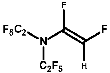
- Sodium borohydride (5.111g, 0.1351mol) was charged to a 500mL, 3-necked flask equipped with overhead stirring, ice bath, thermocouple probe, addition funnel, and a water cooled condenser equipped with a nitrogen inlet. Anhydrous diglyme solvent (135mL) was then batch charged to the reactor flask. After the reaction mixture was chilled to near 0°C, the perfluorinated vinyl amine, (C2F5)2N-CF=CF2 (90.00g, 0.2702mol), was charged to the addition funnel and added dropwise with stirring to the reaction mixture while maintaining cooling in ice bath. The dropwise addition was conducted over a 70min period. Once all of the perfluorinated vinyl amine starting material was added, the reaction was allowed to proceed for an additional 15 minutes with stirring near 0°C. Then the reaction mixture was quenched by the gradual addition of deionized water (140mL, added dropwise initially) with stirring. Once water addition was complete, 34.4 wt% H3PO4(aq) (22.43g) was added dropwise (to minimize exotherm and foaming) with stirring between 0-6°C to adjust the pH of the reaction solution and destroy residual borohydride reagent. The stirring was stopped, and the reaction mixture was transferred to a 1.0L separatory funnel while still cold to allow separation and isolation of the dense fluorinated product phase. The crude fluorinated product was then washed with five 150mL portions of DI water. The final water-washed lower liquid phase was drained to a 100mL Erlenmeyer flask giving 59.25g (69.6% of theory) of crude product. This material was dried over activated 3A molecular sieves (6.2g) and treated with a small amount of powdered NaF (4.0g) in preparation for purification by fractional distillation.
- After drying, the crude product was filtered through a 10 micron polyethylene fritted disposable filter funnel to remove molecular sieves and NaF, then transferred to a 50mL, 3-necked, round bottom flask. An additional 0.63g of fresh NaF powder plus a magnetic stir bar were charged to the flask and the product was fractionally distilled with stirring at atmospheric pressure under a nitrogen atmosphere using a 40-plate concentric tube distillation column equipped with a liquid splitter distillation head and a water cooled condenser. The desired product was collected at a head temperature of 70.5-71.1°C (B.P.) yielding a total of 40.8g (47.9% of theory) (C2F5)2N-CF=CHF (mixture of E and Z isomers). The structure of the desired product was confirmed by GC/MS and 1H and 19F NMR with an overall purity of 97.8%.
-

- In a 50mL, 3-neck round bottom flask equipped with magnetic stirring, cold water condenser, N2 bubbler, thermocouple probe, and addition funnel, sodium borohydride (0.55 g, 14.5 mmol) and diglyme (15g, 111.8 mmol) were charged. The mixture was stirred and cooled to approximately 0°C in an ice bath. 4-[2,2-difluoro-1-(trifluoromethyl)vinyl]-2,2,3,3,5,5,6,6-octofluoromorpholine (10.0g, 27.7 mmol) was added dropwise with stirring via the addition funnel to the reaction mixture. The starting fluorochemical was charged at approximately ½ drop/second to control the reaction exotherm. Addition was completed over 40 minutes during which time the maximum temperature of the reaction mixture reached 20.2°C. Once the addition was complete, the reaction mixture was stirred at room temperature for an additional 60 minutes before the reaction was quenched with 25mL of water and then acidified to a pH of 3 using 34.4% phosphoric acid. The lower fluorochemical phase was then isolated and washed with an additional 40g of water. After phase separation from the aqueous phase, the isolated mass of crude fluorochemical product was 7.36g. The crude product was submitted for GC/MS analysis and 1H, 13C and 19F NMR spectroscopy. GC-MS analysis revealed that the product contained a mixture of mono-, di-, and tri-hydrido substituted products. 1H, 13C and 19F NMR analysis allowed assignment of the main constituents of the fluorochemical product mixture as 2,2,3,3,5,5,6,6-octafluoro-4-[(E&Z)-2-fluoro-1-trifluoromethyl)vinyl]morpholine (26.6 wt%, combined E&Z isomers), 2,2,3,3,5,5,6,6-octafluoro-4-[1-trifluoromethyl)vinyl]morpholine (22.7 wt%), and 4-(2,2-difluoro-1-methyl-vinyl)-2,2,3,3,5,5,6,6-octafluoro-morpholine (20.9 wt%).
- Other embodiments of the invention are within the scope of the appended claims.
-

- Sodium borohydride (7.1 g, 190 mmol) was charged to a 3-neck, 500 mL round-bottom flask equipped with a magnetic stir bar, water-cooled condenser, addition funnel, and temperature probe. The flask was then evacuated and back-filled with N2 three times before the addition of tetraglyme (60 g). The addition funnel was then charged with 2,3,3,3-tetrafluoro-2-(perfluoromorpholino)propanoyl fluoride (49.9 g, 132 mmol) which was subsequently added dropwise to the tetraglyme/sodium borohydride mixture over the course of 1 h. The internal temperature of the reaction mixture was not allowed to reach higher than 50°C. After complete addition, the internal reaction temperature was raised to 80°C. After stirring overnight, the reaction mixture was allowed to cool to room temperature followed by the dropwise addition of methanol (80mL) and then water (50 mL). The fluorous phase was collected and purified via single-plate vacuum distillation (0.1 torr, 27.5 °C head temperature) to give 2,3,3,3-tetrafluoro-2-(perfluoromorpholino)propan-1-ol (26.4 g, 55% yield) as a colorless liquid. The afforded product was used in the next step.
- A 3-neck, 200 mL round bottom flask equipped with a short path distillation head and overhead stirrer was evacuated and backfilled with N2 three times before the addition of titanium(IV) chloride (5.6 mL, 51 mmol) followed by the slow addition of 2,3,3,3-tetrafluoro-2-(perfluoromorpholino)propan-1-ol (12 g, 33 mmol). The internal temperature was raised to 40 °C followed by a 30 min stir. The mixture was then cooled by ice bath followed by the slow addition of tetraglyme (50 g). Initial addition of tetraglyme produced exotherms resulting in internal temperature spikes of up to 30°C. After complete addition, the flask was removed from the ice bath and allowed to reach room temperature. Zinc dust (7.1 g, 110 mmol) was then added in one portion and the resultant mixture was heated to 85°C. After stirring for 3 hours, the temperature was slowly raised to 210°C at which point the desired product was distilled out of the reaction mixture. The structure was confirmed by GC/MS and 1H, 19F, and 13C NMR spectroscopy to be that of the desired product.
Claims (14)
- A hydrofluoroolefin compound represented by the following general formula (A):
 in which, Rf1 and Rf2 are(i) independently linear or branched fluoroalkyl groups having 1 to 8 carbon atoms and optionally include one or more catenated heteroatoms; or(ii) bonded together to form a ring structure having 4 to 8 carbon atoms and optionally include one or more catenated heteroatoms;α is CF3, F, or H;β is F or H;γ is CF3, F, CF2H, CFH2, or CH3, andthe compound includes a total of 1 to 4 H atoms; andwith the provisos that at least one of α and γ is F or H;when γ is CF3 or F, at least one of α and P is H;when γ is CH3, at least one of α and β is F; andwhen α is CF3, then β is H and γ is F;wherein at least one of Rf1 and Rf2 have two or more carbon atoms;wherein the heteroatom in the catenated heteroatom is selected from oxygen, nitrogen, and sulfur and a catenated nitrogen atom, if present, is a tertiary nitrogen wherein the nitrogen atom is bonded to three perfluorinated carbon atoms.
 - A hydrofluoroolefin compound represented by the following general formula (I):
 in which, Rf'1 and Rf'2 are(i) independently linear or branched fluoroalkyl groups having 1 to 8 carbon atoms and optionally include one or more catenated heteroatoms; or(ii) bonded together to form a ring structure having 4 to 8 carbon atoms and optionally include one or more catenated heteroatoms, andδ and ε are H or F;with the proviso that at least one of δ and ε is H, and wherein at least one of Rf'1 and Rf'2 have two or more carbon atoms;wherein the heteroatom in the catenated heteroatom is selected from oxygen, nitrogen, and sulfur and a catenated nitrogen atom, if present, is a tertiary nitrogen wherein the nitrogen atom is bonded to three perfluorinated carbon atoms.
 - The hydrofluoroolefin compound of claim 2, wherein δ is H and ε is F.
- The hydrofluoroolefin compound of claim 2, wherein δ is H and ε is H.
- A hydrofluoroolefin compound represented by the following general formula (II):
 in which, where Rf"1 and Rf'2 are(i) independently linear or branched fluoroalkyl groups having 1 to 8 carbon atoms and optionally include one or more catenated heteroatoms; or(ii) bonded together to form a ring structure having 4 to 8 carbon atoms and optionally include one or more catenated heteroatoms; andwherein at least one of Rf"1 and Rf'2 have two or more carbon atoms;wherein the heteroatom in the catenated heteroatom is selected from oxygen, nitrogen, and sulfur and a catenated nitrogen atom, if present, is a tertiary nitrogen wherein the nitrogen atom is bonded to three perfluorinated carbon atoms.
 - The hydrofluoroolefin compound of claim 1, wherein the hydrofluoroolefin compound comprises one or more of the following compounds:


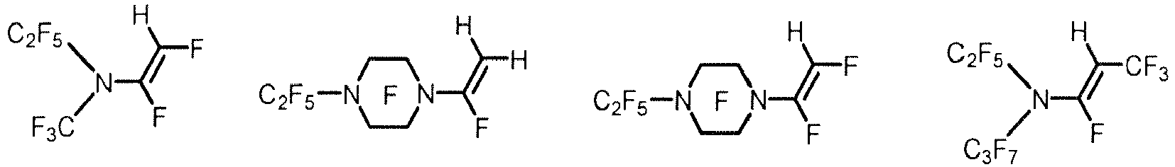

- A working fluid comprising a hydrofluoroolefin compound according to any of claims 1 to 6, wherein the hydrofluoolefin compound is present in the working fluid at an amount of at least 25% by weight based on the total weight of the working fluid.
- A working fluid comprising a hydrofluoroolefin compound represented by the following general formula (A):
 in which, Rf1 and Rf2 are(i) independently linear or branched fluoroalkyl groups having 1 to 8 carbon atoms and optionally include one or more catenated heteroatoms; or(ii) bonded together to form a ring structure having 4 to 8 carbon atoms and optionally include one or more catenated heteroatoms;α is CF3, F, or H;β is F or H;γ is CF3, F, CF2H, CFH2, or CH3; andthe compound includes a total of 1 to 4 H atoms; andwith the provisos that at least one of α and γ is F or H;when γ is CF3 or F, at least one of α and β is H;when γ is CH3, at least one of α and β is F; andwhen α is CF3, then β is H and γ is F;wherein the heteroatom in the catenated heteroatom is selected from oxygen, nitrogen, and sulfur and a catenated nitrogen atom, if present, is a tertiary nitrogen wherein the nitrogen atom is bonded to three perfluorinated carbon atoms;wherein the hydrofluoroolefin compound is present in the working fluid at an amount of at least 25% by weight based on the total weight of the working fluid.
 - A working fluid comprising a hydrofluoroolefin compound represented by the following general formula (I):
 in which, Rf'1 and Rf'2 are(i) independently linear or branched fluoroalkyl groups having 1 to 8 carbon atoms and optionally include one or more catenated heteroatoms; or(ii) bonded together to form a ring structure having 4 to 8 carbon atoms and optionally include one or more catenated heteroatoms; andδ and ε are H or F;with the proviso that at least one of δ and ε is H;wherein the heteroatom in the catenated heteroatom is selected from oxygen, nitrogen, and sulfur and a catenated nitrogen atom, if present, is a tertiary nitrogen wherein the nitrogen atom is bonded to three perfluorinated carbon atoms;wherein the hydrofluoroolefin compound is present in the working fluid at an amount of at least 25% by weight based on the total weight of the working fluid.
 - A working fluid comprising a hydrofluoroolefin compound represented by the following general formula (II):
 in which, where Rf"1 and Rf"2 are(i) independently linear or branched fluoroalkyl groups having 1 to 8 carbon atoms and optionally include one or more catenated heteroatoms; or(ii) bonded together to form a ring structure having 4 to 8 carbon atoms and optionally include one or more catenated heteroatoms;wherein the heteroatom in the catenated heteroatom is selected from oxygen, nitrogen, and sulfur and a catenated nitrogen atom, if present, is a tertiary nitrogen wherein the nitrogen atom is bonded to three perfluorinated carbon atoms;wherein the hydrofluoroolefin compound is present in the working fluid at an amount of at least 25% by weight based on the total weight of the working fluid.
 - An apparatus for heat transfer comprising:a device; anda mechanism for transferring heat to or from the device, the mechanism comprising a heat transfer fluid that comprises a hydrofluoroolefin compound according to any of claims 1 to 6.
- An apparatus for heat transfer according to claim 11, wherein the device is selected from a microprocessor, a semiconductor wafer used to manufacture a semiconductor device, a power control semiconductor, an electrochemical cell, an electrical distribution switch gear, a power transformer, a circuit board, a multi-chip module, a packaged or unpackaged semiconductor device, a fuel cell, and a laser.
- An apparatus for heat transfer according to claim 11, wherein the mechanism for transferring heat is a component in a system for maintaining a temperature or temperature range of an electronic device.
- A method of transferring heat comprising:providing a device; andtransferring heat to or from the device using a heat transfer fluid that comprises a hydrofluoroolefin compound according to any of claims 1 to 6.
Applications Claiming Priority (2)
| Application Number | Priority Date | Filing Date | Title |
|---|---|---|---|
| US201562171446P | 2015-06-05 | 2015-06-05 | |
| PCT/US2016/034514 WO2016196240A1 (en) | 2015-06-05 | 2016-05-27 | Hydrofluoroolefins and methods of using same |
Publications (3)
| Publication Number | Publication Date |
|---|---|
| EP3303435A1 EP3303435A1 (en) | 2018-04-11 |
| EP3303435A4 EP3303435A4 (en) | 2019-02-20 |
| EP3303435B1 true EP3303435B1 (en) | 2020-11-25 |
Family
ID=57442094
Family Applications (1)
| Application Number | Title | Priority Date | Filing Date |
|---|---|---|---|
| EP16804087.1A Active EP3303435B1 (en) | 2015-06-05 | 2016-05-27 | Hydrofluoroolefins and methods of using same |
Country Status (7)
| Country | Link |
|---|---|
| US (1) | US10738001B2 (en) |
| EP (1) | EP3303435B1 (en) |
| JP (1) | JP6749347B2 (en) |
| KR (1) | KR102580755B1 (en) |
| CN (1) | CN107614560A (en) |
| TW (1) | TWI718152B (en) |
| WO (1) | WO2016196240A1 (en) |
Cited By (1)
| Publication number | Priority date | Publication date | Assignee | Title |
|---|---|---|---|---|
| WO2023281421A1 (en) * | 2021-07-07 | 2023-01-12 | 3M Innovative Properties Company | Hydrofluoroolefins and uses thereof |
Families Citing this family (19)
| Publication number | Priority date | Publication date | Assignee | Title |
|---|---|---|---|---|
| JP6738837B2 (en) * | 2015-06-05 | 2020-08-12 | スリーエム イノベイティブ プロパティズ カンパニー | Hydrofluoroolefin and method of using the same |
| WO2017095732A1 (en) | 2015-12-02 | 2017-06-08 | 3M Innovative Properties Company | Allylic terminally unsaturated hydrofluoroamine and allylic terminally unsaturated hydrofluoroether compounds and methods of using the same |
| EP3390464B1 (en) | 2015-12-17 | 2020-10-21 | 3M Innovative Properties Company | Aqueous dispersions of amine-containing fluorinated polymers and methods of making and using the same |
| WO2017195070A1 (en) * | 2016-05-09 | 2017-11-16 | 3M Innovative Properties Company | Hydrofluoroolefins and methods of using same |
| WO2018039096A1 (en) | 2016-08-22 | 2018-03-01 | 3M Innovative Properties Company | Propenylamines and methods of making and using same |
| EP3515886A4 (en) * | 2016-09-26 | 2020-05-06 | 3M Innovative Properties Company | Nitrogen and/or oxygen-containing hydrofluoroolefins and methods of making and using the same |
| JP7120713B2 (en) * | 2016-12-21 | 2022-08-17 | スリーエム イノベイティブ プロパティズ カンパニー | Hydrofluoroolefin and its use |
| CN109072054B (en) * | 2017-03-21 | 2021-10-19 | 3M创新有限公司 | Heat transfer fluid and method of use |
| EP3634931B1 (en) | 2017-06-07 | 2024-12-11 | 3M Innovative Properties Company | Immersion cooling |
| WO2019220293A1 (en) * | 2018-05-15 | 2019-11-21 | 3M Innovative Properties Company | Perfluoroaminoolefins and methods of making and using the same |
| JP7624921B2 (en) * | 2018-12-20 | 2025-01-31 | スリーエム イノベイティブ プロパティズ カンパニー | Hydrofluoroolefins and methods for using same |
| CN113796173B (en) | 2018-12-21 | 2025-04-08 | 霍尼韦尔国际公司 | Heat transfer methods, systems and fluids |
| WO2020136533A1 (en) * | 2018-12-26 | 2020-07-02 | 3M Innovative Properties Company | Hydrochlorofluoroolefins and methods of using same |
| US11932589B2 (en) * | 2019-02-19 | 2024-03-19 | 3M Innovative Properties Company | Hydrofluoroolefins and methods of using same |
| WO2020187839A1 (en) * | 2019-03-18 | 2020-09-24 | Solvay Specialty Polymers Italy S.P.A. | Heat exchange method using fluorinated compounds having a low gwp |
| KR102853204B1 (en) * | 2019-06-12 | 2025-08-29 | 쓰리엠 이노베이티브 프로퍼티즈 컴파니 | Fluorinated aromatic substances and methods of using the same |
| CN116348968A (en) | 2020-10-22 | 2023-06-27 | Agc株式会社 | Electrical Equipment |
| US20230402680A1 (en) | 2020-11-03 | 2023-12-14 | 3M Innovative Properties Company | Fluids for immersion cooling of electronic components |
| JPWO2022131226A1 (en) * | 2020-12-16 | 2022-06-23 |
Family Cites Families (32)
| Publication number | Priority date | Publication date | Assignee | Title |
|---|---|---|---|---|
| US4782148A (en) | 1985-07-23 | 1988-11-01 | Agency Of Industrial Science & Technology | Method for production of perfluoro N-(vinyl)amines |
| JPS6470444A (en) | 1987-09-10 | 1989-03-15 | Agency Ind Science Techn | Novel perfluoroalkenylamine and production thereof |
| JPS6470445A (en) | 1988-07-23 | 1989-03-15 | Agency Ind Science Techn | Novel perfluoroalkenylamine and production thereof |
| US5396000A (en) | 1993-05-24 | 1995-03-07 | E. I. Du Pont De Nemours And Company | Process for the manufacture of 1,1,1,2,3,-pentafluoropropane |
| JP4031052B2 (en) | 1997-01-31 | 2008-01-09 | イー・アイ・デュポン・ドウ・ヌムール・アンド・カンパニー | Contact production of pentafluoropropene |
| US5986151A (en) | 1997-02-05 | 1999-11-16 | Alliedsignal Inc. | Fluorinated propenes from pentafluoropropane |
| US6203944B1 (en) | 1998-03-26 | 2001-03-20 | 3M Innovative Properties Company | Electrode for a lithium battery |
| EP1234261A4 (en) | 1999-07-07 | 2003-02-19 | Michael T Rossides | Expected value methods and systems for paying and qualifying |
| US9994750B2 (en) * | 2002-10-25 | 2018-06-12 | Honeywell International Inc. | Compositions containing fluorine substituted olefins and methods and systems using same |
| US7279451B2 (en) * | 2002-10-25 | 2007-10-09 | Honeywell International Inc. | Compositions containing fluorine substituted olefins |
| US9085504B2 (en) * | 2002-10-25 | 2015-07-21 | Honeywell International Inc. | Solvent compositions containing fluorine substituted olefins and methods and systems using same |
| US8530708B2 (en) | 2003-07-25 | 2013-09-10 | Honeywell International Inc. | Processes for selective dehydrohalogenation of halogenated alkanes |
| US9499729B2 (en) * | 2006-06-26 | 2016-11-22 | Honeywell International Inc. | Compositions and methods containing fluorine substituted olefins |
| US7560602B2 (en) | 2005-11-03 | 2009-07-14 | Honeywell International Inc. | Process for manufacture of fluorinated olefins |
| US8193397B2 (en) | 2006-12-06 | 2012-06-05 | 3M Innovative Properties Company | Hydrofluoroether compounds and processes for their preparation and use |
| WO2009019219A2 (en) | 2007-08-03 | 2009-02-12 | Solvay (Société Anonyme) | Methods of using a solvent or a foam blowing agent |
| US8820079B2 (en) | 2008-12-05 | 2014-09-02 | Honeywell International Inc. | Chloro- and bromo-fluoro olefin compounds useful as organic rankine cycle working fluids |
| US8261560B2 (en) * | 2009-11-02 | 2012-09-11 | 3M Innovative Properties Company | Methods of using hydrofluoroethers as heat transfer fluids |
| US9796691B2 (en) * | 2011-06-10 | 2017-10-24 | 3M Innovative Properties | Partially fluorinated ketones and methods of making and using the same |
| CN105452208B (en) * | 2013-07-25 | 2018-05-01 | 3M创新有限公司 | Nitrogen-containing hydrofluoroether and its preparation method |
| KR102309799B1 (en) * | 2013-12-20 | 2021-10-08 | 쓰리엠 이노베이티브 프로퍼티즈 컴파니 | Fluorinated olefins as working fluids and methods of using same |
| US10030185B2 (en) * | 2014-07-16 | 2018-07-24 | 3M Innovative Properties Company | Hydrofluoroether olefins and methods of using same |
| EP3197945B1 (en) * | 2014-09-23 | 2020-10-21 | 3M Innovative Properties Company | Nitrogen containing hydrofluoroethers and methods of using same |
| WO2016064585A1 (en) * | 2014-10-24 | 2016-04-28 | 3M Innovative Properties Company | Segregated fluorinated esters |
| US20160262490A1 (en) * | 2015-03-13 | 2016-09-15 | Honeywell International Inc. | Foams, foamable compositions and methods of making integral skin foams |
| JP6738837B2 (en) * | 2015-06-05 | 2020-08-12 | スリーエム イノベイティブ プロパティズ カンパニー | Hydrofluoroolefin and method of using the same |
| WO2017095732A1 (en) * | 2015-12-02 | 2017-06-08 | 3M Innovative Properties Company | Allylic terminally unsaturated hydrofluoroamine and allylic terminally unsaturated hydrofluoroether compounds and methods of using the same |
| EP3390464B1 (en) * | 2015-12-17 | 2020-10-21 | 3M Innovative Properties Company | Aqueous dispersions of amine-containing fluorinated polymers and methods of making and using the same |
| US10301293B2 (en) * | 2016-03-11 | 2019-05-28 | 3M Innovative Properties Company | Amine-containing cyclic hydrofluoroethers and methods of using the same |
| CN108713014A (en) * | 2016-03-11 | 2018-10-26 | 3M创新有限公司 | Amine-containing acyclic hydrofluoroethers and methods of use thereof |
| WO2017195070A1 (en) * | 2016-05-09 | 2017-11-16 | 3M Innovative Properties Company | Hydrofluoroolefins and methods of using same |
| EP3515886A4 (en) * | 2016-09-26 | 2020-05-06 | 3M Innovative Properties Company | Nitrogen and/or oxygen-containing hydrofluoroolefins and methods of making and using the same |
-
2016
- 2016-05-27 CN CN201680032493.4A patent/CN107614560A/en active Pending
- 2016-05-27 KR KR1020187000130A patent/KR102580755B1/en active Active
- 2016-05-27 US US15/578,280 patent/US10738001B2/en active Active
- 2016-05-27 EP EP16804087.1A patent/EP3303435B1/en active Active
- 2016-05-27 JP JP2017562981A patent/JP6749347B2/en active Active
- 2016-05-27 WO PCT/US2016/034514 patent/WO2016196240A1/en not_active Ceased
- 2016-06-03 TW TW105117671A patent/TWI718152B/en active
Non-Patent Citations (1)
| Title |
|---|
| None * |
Cited By (1)
| Publication number | Priority date | Publication date | Assignee | Title |
|---|---|---|---|---|
| WO2023281421A1 (en) * | 2021-07-07 | 2023-01-12 | 3M Innovative Properties Company | Hydrofluoroolefins and uses thereof |
Also Published As
| Publication number | Publication date |
|---|---|
| EP3303435A4 (en) | 2019-02-20 |
| US20180141893A1 (en) | 2018-05-24 |
| TWI718152B (en) | 2021-02-11 |
| JP2018525327A (en) | 2018-09-06 |
| KR102580755B1 (en) | 2023-09-19 |
| US10738001B2 (en) | 2020-08-11 |
| TW201714879A (en) | 2017-05-01 |
| KR20180015719A (en) | 2018-02-13 |
| WO2016196240A1 (en) | 2016-12-08 |
| EP3303435A1 (en) | 2018-04-11 |
| JP6749347B2 (en) | 2020-09-02 |
| CN107614560A (en) | 2018-01-19 |
Similar Documents
| Publication | Publication Date | Title |
|---|---|---|
| EP3303435B1 (en) | Hydrofluoroolefins and methods of using same | |
| EP3197945B1 (en) | Nitrogen containing hydrofluoroethers and methods of using same | |
| EP3455322B1 (en) | Hydrofluoroolefins and methods of using same | |
| EP3169745B1 (en) | Hydrofluoroether olefins and methods of using same | |
| US10266472B2 (en) | Hydrofluoroolefins and methods of using same | |
| US11858875B2 (en) | Propenylamines and methods of making and using same | |
| US11046677B2 (en) | Hydrofluoroolefins and methods of using same | |
| US10577335B2 (en) | Allylic terminally unsaturated hydrofluoroamine and allylic terminally unsaturated hydrofluoroether compounds and methods of using the same |
Legal Events
| Date | Code | Title | Description |
|---|---|---|---|
| STAA | Information on the status of an ep patent application or granted ep patent |
Free format text: STATUS: THE INTERNATIONAL PUBLICATION HAS BEEN MADE |
|
| PUAI | Public reference made under article 153(3) epc to a published international application that has entered the european phase |
Free format text: ORIGINAL CODE: 0009012 |
|
| STAA | Information on the status of an ep patent application or granted ep patent |
Free format text: STATUS: REQUEST FOR EXAMINATION WAS MADE |
|
| 17P | Request for examination filed |
Effective date: 20171205 |
|
| AK | Designated contracting states |
Kind code of ref document: A1 Designated state(s): AL AT BE BG CH CY CZ DE DK EE ES FI FR GB GR HR HU IE IS IT LI LT LU LV MC MK MT NL NO PL PT RO RS SE SI SK SM TR |
|
| AX | Request for extension of the european patent |
Extension state: BA ME |
|
| DAV | Request for validation of the european patent (deleted) | ||
| DAX | Request for extension of the european patent (deleted) | ||
| A4 | Supplementary search report drawn up and despatched |
Effective date: 20190123 |
|
| RIC1 | Information provided on ipc code assigned before grant |
Ipc: C14C 1/00 20060101ALI20190114BHEP Ipc: C07D 207/10 20060101ALI20190114BHEP Ipc: C07C 211/24 20060101ALI20190114BHEP Ipc: C08G 18/48 20060101AFI20190114BHEP Ipc: C08J 9/00 20060101ALI20190114BHEP Ipc: C07D 265/30 20060101ALI20190114BHEP |
|
| GRAP | Despatch of communication of intention to grant a patent |
Free format text: ORIGINAL CODE: EPIDOSNIGR1 |
|
| STAA | Information on the status of an ep patent application or granted ep patent |
Free format text: STATUS: GRANT OF PATENT IS INTENDED |
|
| INTG | Intention to grant announced |
Effective date: 20200603 |
|
| GRAS | Grant fee paid |
Free format text: ORIGINAL CODE: EPIDOSNIGR3 |
|
| GRAA | (expected) grant |
Free format text: ORIGINAL CODE: 0009210 |
|
| STAA | Information on the status of an ep patent application or granted ep patent |
Free format text: STATUS: THE PATENT HAS BEEN GRANTED |
|
| AK | Designated contracting states |
Kind code of ref document: B1 Designated state(s): AL AT BE BG CH CY CZ DE DK EE ES FI FR GB GR HR HU IE IS IT LI LT LU LV MC MK MT NL NO PL PT RO RS SE SI SK SM TR |
|
| REG | Reference to a national code |
Ref country code: GB Ref legal event code: FG4D |
|
| REG | Reference to a national code |
Ref country code: CH Ref legal event code: EP |
|
| REG | Reference to a national code |
Ref country code: DE Ref legal event code: R096 Ref document number: 602016048696 Country of ref document: DE |
|
| REG | Reference to a national code |
Ref country code: AT Ref legal event code: REF Ref document number: 1338221 Country of ref document: AT Kind code of ref document: T Effective date: 20201215 |
|
| REG | Reference to a national code |
Ref country code: IE Ref legal event code: FG4D |
|
| REG | Reference to a national code |
Ref country code: AT Ref legal event code: MK05 Ref document number: 1338221 Country of ref document: AT Kind code of ref document: T Effective date: 20201125 |
|
| REG | Reference to a national code |
Ref country code: NL Ref legal event code: MP Effective date: 20201125 |
|
| PG25 | Lapsed in a contracting state [announced via postgrant information from national office to epo] |
Ref country code: NO Free format text: LAPSE BECAUSE OF FAILURE TO SUBMIT A TRANSLATION OF THE DESCRIPTION OR TO PAY THE FEE WITHIN THE PRESCRIBED TIME-LIMIT Effective date: 20210225 Ref country code: PT Free format text: LAPSE BECAUSE OF FAILURE TO SUBMIT A TRANSLATION OF THE DESCRIPTION OR TO PAY THE FEE WITHIN THE PRESCRIBED TIME-LIMIT Effective date: 20210325 Ref country code: RS Free format text: LAPSE BECAUSE OF FAILURE TO SUBMIT A TRANSLATION OF THE DESCRIPTION OR TO PAY THE FEE WITHIN THE PRESCRIBED TIME-LIMIT Effective date: 20201125 Ref country code: FI Free format text: LAPSE BECAUSE OF FAILURE TO SUBMIT A TRANSLATION OF THE DESCRIPTION OR TO PAY THE FEE WITHIN THE PRESCRIBED TIME-LIMIT Effective date: 20201125 Ref country code: GR Free format text: LAPSE BECAUSE OF FAILURE TO SUBMIT A TRANSLATION OF THE DESCRIPTION OR TO PAY THE FEE WITHIN THE PRESCRIBED TIME-LIMIT Effective date: 20210226 |
|
| PG25 | Lapsed in a contracting state [announced via postgrant information from national office to epo] |
Ref country code: SE Free format text: LAPSE BECAUSE OF FAILURE TO SUBMIT A TRANSLATION OF THE DESCRIPTION OR TO PAY THE FEE WITHIN THE PRESCRIBED TIME-LIMIT Effective date: 20201125 Ref country code: BG Free format text: LAPSE BECAUSE OF FAILURE TO SUBMIT A TRANSLATION OF THE DESCRIPTION OR TO PAY THE FEE WITHIN THE PRESCRIBED TIME-LIMIT Effective date: 20210225 Ref country code: PL Free format text: LAPSE BECAUSE OF FAILURE TO SUBMIT A TRANSLATION OF THE DESCRIPTION OR TO PAY THE FEE WITHIN THE PRESCRIBED TIME-LIMIT Effective date: 20201125 Ref country code: LV Free format text: LAPSE BECAUSE OF FAILURE TO SUBMIT A TRANSLATION OF THE DESCRIPTION OR TO PAY THE FEE WITHIN THE PRESCRIBED TIME-LIMIT Effective date: 20201125 Ref country code: IS Free format text: LAPSE BECAUSE OF FAILURE TO SUBMIT A TRANSLATION OF THE DESCRIPTION OR TO PAY THE FEE WITHIN THE PRESCRIBED TIME-LIMIT Effective date: 20210325 Ref country code: AT Free format text: LAPSE BECAUSE OF FAILURE TO SUBMIT A TRANSLATION OF THE DESCRIPTION OR TO PAY THE FEE WITHIN THE PRESCRIBED TIME-LIMIT Effective date: 20201125 |
|
| REG | Reference to a national code |
Ref country code: LT Ref legal event code: MG9D |
|
| PG25 | Lapsed in a contracting state [announced via postgrant information from national office to epo] |
Ref country code: HR Free format text: LAPSE BECAUSE OF FAILURE TO SUBMIT A TRANSLATION OF THE DESCRIPTION OR TO PAY THE FEE WITHIN THE PRESCRIBED TIME-LIMIT Effective date: 20201125 |
|
| PG25 | Lapsed in a contracting state [announced via postgrant information from national office to epo] |
Ref country code: EE Free format text: LAPSE BECAUSE OF FAILURE TO SUBMIT A TRANSLATION OF THE DESCRIPTION OR TO PAY THE FEE WITHIN THE PRESCRIBED TIME-LIMIT Effective date: 20201125 Ref country code: CZ Free format text: LAPSE BECAUSE OF FAILURE TO SUBMIT A TRANSLATION OF THE DESCRIPTION OR TO PAY THE FEE WITHIN THE PRESCRIBED TIME-LIMIT Effective date: 20201125 Ref country code: LT Free format text: LAPSE BECAUSE OF FAILURE TO SUBMIT A TRANSLATION OF THE DESCRIPTION OR TO PAY THE FEE WITHIN THE PRESCRIBED TIME-LIMIT Effective date: 20201125 Ref country code: SM Free format text: LAPSE BECAUSE OF FAILURE TO SUBMIT A TRANSLATION OF THE DESCRIPTION OR TO PAY THE FEE WITHIN THE PRESCRIBED TIME-LIMIT Effective date: 20201125 Ref country code: SK Free format text: LAPSE BECAUSE OF FAILURE TO SUBMIT A TRANSLATION OF THE DESCRIPTION OR TO PAY THE FEE WITHIN THE PRESCRIBED TIME-LIMIT Effective date: 20201125 Ref country code: RO Free format text: LAPSE BECAUSE OF FAILURE TO SUBMIT A TRANSLATION OF THE DESCRIPTION OR TO PAY THE FEE WITHIN THE PRESCRIBED TIME-LIMIT Effective date: 20201125 |
|
| REG | Reference to a national code |
Ref country code: DE Ref legal event code: R097 Ref document number: 602016048696 Country of ref document: DE |
|
| PG25 | Lapsed in a contracting state [announced via postgrant information from national office to epo] |
Ref country code: DK Free format text: LAPSE BECAUSE OF FAILURE TO SUBMIT A TRANSLATION OF THE DESCRIPTION OR TO PAY THE FEE WITHIN THE PRESCRIBED TIME-LIMIT Effective date: 20201125 |
|
| PLBE | No opposition filed within time limit |
Free format text: ORIGINAL CODE: 0009261 |
|
| STAA | Information on the status of an ep patent application or granted ep patent |
Free format text: STATUS: NO OPPOSITION FILED WITHIN TIME LIMIT |
|
| PG25 | Lapsed in a contracting state [announced via postgrant information from national office to epo] |
Ref country code: IT Free format text: LAPSE BECAUSE OF FAILURE TO SUBMIT A TRANSLATION OF THE DESCRIPTION OR TO PAY THE FEE WITHIN THE PRESCRIBED TIME-LIMIT Effective date: 20201125 Ref country code: AL Free format text: LAPSE BECAUSE OF FAILURE TO SUBMIT A TRANSLATION OF THE DESCRIPTION OR TO PAY THE FEE WITHIN THE PRESCRIBED TIME-LIMIT Effective date: 20201125 Ref country code: NL Free format text: LAPSE BECAUSE OF FAILURE TO SUBMIT A TRANSLATION OF THE DESCRIPTION OR TO PAY THE FEE WITHIN THE PRESCRIBED TIME-LIMIT Effective date: 20201125 |
|
| 26N | No opposition filed |
Effective date: 20210826 |
|
| PG25 | Lapsed in a contracting state [announced via postgrant information from national office to epo] |
Ref country code: SI Free format text: LAPSE BECAUSE OF FAILURE TO SUBMIT A TRANSLATION OF THE DESCRIPTION OR TO PAY THE FEE WITHIN THE PRESCRIBED TIME-LIMIT Effective date: 20201125 |
|
| REG | Reference to a national code |
Ref country code: CH Ref legal event code: PL |
|
| GBPC | Gb: european patent ceased through non-payment of renewal fee |
Effective date: 20210527 |
|
| PG25 | Lapsed in a contracting state [announced via postgrant information from national office to epo] |
Ref country code: ES Free format text: LAPSE BECAUSE OF FAILURE TO SUBMIT A TRANSLATION OF THE DESCRIPTION OR TO PAY THE FEE WITHIN THE PRESCRIBED TIME-LIMIT Effective date: 20201125 Ref country code: CH Free format text: LAPSE BECAUSE OF NON-PAYMENT OF DUE FEES Effective date: 20210531 Ref country code: LI Free format text: LAPSE BECAUSE OF NON-PAYMENT OF DUE FEES Effective date: 20210531 Ref country code: MC Free format text: LAPSE BECAUSE OF FAILURE TO SUBMIT A TRANSLATION OF THE DESCRIPTION OR TO PAY THE FEE WITHIN THE PRESCRIBED TIME-LIMIT Effective date: 20201125 Ref country code: LU Free format text: LAPSE BECAUSE OF NON-PAYMENT OF DUE FEES Effective date: 20210527 |
|
| REG | Reference to a national code |
Ref country code: BE Ref legal event code: MM Effective date: 20210531 |
|
| PG25 | Lapsed in a contracting state [announced via postgrant information from national office to epo] |
Ref country code: IE Free format text: LAPSE BECAUSE OF NON-PAYMENT OF DUE FEES Effective date: 20210527 Ref country code: GB Free format text: LAPSE BECAUSE OF NON-PAYMENT OF DUE FEES Effective date: 20210527 |
|
| PG25 | Lapsed in a contracting state [announced via postgrant information from national office to epo] |
Ref country code: IS Free format text: LAPSE BECAUSE OF FAILURE TO SUBMIT A TRANSLATION OF THE DESCRIPTION OR TO PAY THE FEE WITHIN THE PRESCRIBED TIME-LIMIT Effective date: 20210325 Ref country code: FR Free format text: LAPSE BECAUSE OF NON-PAYMENT OF DUE FEES Effective date: 20210531 |
|
| PG25 | Lapsed in a contracting state [announced via postgrant information from national office to epo] |
Ref country code: BE Free format text: LAPSE BECAUSE OF NON-PAYMENT OF DUE FEES Effective date: 20210531 |
|
| PG25 | Lapsed in a contracting state [announced via postgrant information from national office to epo] |
Ref country code: HU Free format text: LAPSE BECAUSE OF FAILURE TO SUBMIT A TRANSLATION OF THE DESCRIPTION OR TO PAY THE FEE WITHIN THE PRESCRIBED TIME-LIMIT; INVALID AB INITIO Effective date: 20160527 |
|
| PG25 | Lapsed in a contracting state [announced via postgrant information from national office to epo] |
Ref country code: CY Free format text: LAPSE BECAUSE OF FAILURE TO SUBMIT A TRANSLATION OF THE DESCRIPTION OR TO PAY THE FEE WITHIN THE PRESCRIBED TIME-LIMIT Effective date: 20201125 |
|
| P01 | Opt-out of the competence of the unified patent court (upc) registered |
Effective date: 20230530 |
|
| PG25 | Lapsed in a contracting state [announced via postgrant information from national office to epo] |
Ref country code: MK Free format text: LAPSE BECAUSE OF FAILURE TO SUBMIT A TRANSLATION OF THE DESCRIPTION OR TO PAY THE FEE WITHIN THE PRESCRIBED TIME-LIMIT Effective date: 20201125 |
|
| PG25 | Lapsed in a contracting state [announced via postgrant information from national office to epo] |
Ref country code: MT Free format text: LAPSE BECAUSE OF FAILURE TO SUBMIT A TRANSLATION OF THE DESCRIPTION OR TO PAY THE FEE WITHIN THE PRESCRIBED TIME-LIMIT Effective date: 20201125 |
|
| PGFP | Annual fee paid to national office [announced via postgrant information from national office to epo] |
Ref country code: DE Payment date: 20250423 Year of fee payment: 10 |
|
| PG25 | Lapsed in a contracting state [announced via postgrant information from national office to epo] |
Ref country code: TR Free format text: LAPSE BECAUSE OF FAILURE TO SUBMIT A TRANSLATION OF THE DESCRIPTION OR TO PAY THE FEE WITHIN THE PRESCRIBED TIME-LIMIT Effective date: 20201125 |