EP3302142B1 - Shoe soles for midfoot impact region - Google Patents
Shoe soles for midfoot impact region Download PDFInfo
- Publication number
- EP3302142B1 EP3302142B1 EP15745590.8A EP15745590A EP3302142B1 EP 3302142 B1 EP3302142 B1 EP 3302142B1 EP 15745590 A EP15745590 A EP 15745590A EP 3302142 B1 EP3302142 B1 EP 3302142B1
- Authority
- EP
- European Patent Office
- Prior art keywords
- region
- hardness
- cushioning element
- sole
- midfoot
- Prior art date
- Legal status (The legal status is an assumption and is not a legal conclusion. Google has not performed a legal analysis and makes no representation as to the accuracy of the status listed.)
- Active
Links
- 210000000452 mid-foot Anatomy 0.000 title claims description 126
- 210000004744 fore-foot Anatomy 0.000 claims description 111
- 230000003014 reinforcing effect Effects 0.000 claims description 23
- 210000002683 foot Anatomy 0.000 claims description 18
- 238000010276 construction Methods 0.000 claims description 9
- 235000019589 hardness Nutrition 0.000 claims 35
- 210000000474 heel Anatomy 0.000 description 93
- 239000000463 material Substances 0.000 description 16
- 238000010521 absorption reaction Methods 0.000 description 10
- 238000005096 rolling process Methods 0.000 description 10
- 230000035939 shock Effects 0.000 description 9
- 210000000459 calcaneus Anatomy 0.000 description 4
- 230000005021 gait Effects 0.000 description 4
- 238000013016 damping Methods 0.000 description 3
- 239000006260 foam Substances 0.000 description 3
- 229920005830 Polyurethane Foam Polymers 0.000 description 2
- 230000000295 complement effect Effects 0.000 description 2
- 239000005038 ethylene vinyl acetate Substances 0.000 description 2
- 239000000835 fiber Substances 0.000 description 2
- 210000003205 muscle Anatomy 0.000 description 2
- 229920003225 polyurethane elastomer Polymers 0.000 description 2
- 239000011496 polyurethane foam Substances 0.000 description 2
- 239000007779 soft material Substances 0.000 description 2
- 229920001875 Ebonite Polymers 0.000 description 1
- 206010060820 Joint injury Diseases 0.000 description 1
- 206010061223 Ligament injury Diseases 0.000 description 1
- 208000029549 Muscle injury Diseases 0.000 description 1
- 239000004677 Nylon Substances 0.000 description 1
- 208000021945 Tendon injury Diseases 0.000 description 1
- 238000005299 abrasion Methods 0.000 description 1
- 238000004026 adhesive bonding Methods 0.000 description 1
- 239000002131 composite material Substances 0.000 description 1
- 230000007423 decrease Effects 0.000 description 1
- 230000001419 dependent effect Effects 0.000 description 1
- 230000000368 destabilizing effect Effects 0.000 description 1
- 239000013013 elastic material Substances 0.000 description 1
- 210000003041 ligament Anatomy 0.000 description 1
- 210000001872 metatarsal bone Anatomy 0.000 description 1
- VNWKTOKETHGBQD-UHFFFAOYSA-N methane Chemical class C VNWKTOKETHGBQD-UHFFFAOYSA-N 0.000 description 1
- 238000000465 moulding Methods 0.000 description 1
- 230000003387 muscular Effects 0.000 description 1
- 229920001778 nylon Polymers 0.000 description 1
- 230000001737 promoting effect Effects 0.000 description 1
- 230000000284 resting effect Effects 0.000 description 1
Images


Classifications
-
- A—HUMAN NECESSITIES
- A43—FOOTWEAR
- A43B—CHARACTERISTIC FEATURES OF FOOTWEAR; PARTS OF FOOTWEAR
- A43B13/00—Soles; Sole-and-heel integral units
- A43B13/14—Soles; Sole-and-heel integral units characterised by the constructive form
- A43B13/143—Soles; Sole-and-heel integral units characterised by the constructive form provided with wedged, concave or convex end portions, e.g. for improving roll-off of the foot
- A43B13/145—Convex portions, e.g. with a bump or projection, e.g. 'Masai' type shoes
-
- A—HUMAN NECESSITIES
- A43—FOOTWEAR
- A43B—CHARACTERISTIC FEATURES OF FOOTWEAR; PARTS OF FOOTWEAR
- A43B13/00—Soles; Sole-and-heel integral units
- A43B13/14—Soles; Sole-and-heel integral units characterised by the constructive form
- A43B13/18—Resilient soles
- A43B13/181—Resiliency achieved by the structure of the sole
- A43B13/186—Differential cushioning region, e.g. cushioning located under the ball of the foot
-
- A—HUMAN NECESSITIES
- A43—FOOTWEAR
- A43B—CHARACTERISTIC FEATURES OF FOOTWEAR; PARTS OF FOOTWEAR
- A43B13/00—Soles; Sole-and-heel integral units
- A43B13/02—Soles; Sole-and-heel integral units characterised by the material
- A43B13/12—Soles with several layers of different materials
- A43B13/125—Soles with several layers of different materials characterised by the midsole or middle layer
-
- A—HUMAN NECESSITIES
- A43—FOOTWEAR
- A43B—CHARACTERISTIC FEATURES OF FOOTWEAR; PARTS OF FOOTWEAR
- A43B13/00—Soles; Sole-and-heel integral units
- A43B13/14—Soles; Sole-and-heel integral units characterised by the constructive form
- A43B13/18—Resilient soles
- A43B13/187—Resiliency achieved by the features of the material, e.g. foam, non liquid materials
- A43B13/188—Differential cushioning regions
Definitions
- the field relates generally to articles of footwear and, more specifically, to shoe soles for use in articles of footwear designed for a midfoot impact region.
- Articles of footwear such as shoes, generally include a shoe sole and an upper affixed to the shoe sole which surrounds a foot resting on the sole.
- Some known shoe soles are designed to provide a rolling action on a user's foot, and tend to have a destabilizing effect, requiring a more active or "dynamic" response from the user's muscular and skeletal systems as compared to passive walking or running.
- Active walking as compared to passive walking, provides numerous benefits, including training muscles that are typically neglected in passive walking, improving posture and gait pattern, and alleviating back, hip, leg, and foot ailments as well as joint, muscle, ligament, and tendon injuries.
- shoe soles are designed to provide a rolling action during walking, and generally include a relatively soft material in the heel region of the shoe sole.
- shoe soles designed for walking may provide less than optimal rolling action for running, as well as less than optimal cushioning and support for running.
- An example of such a shoe sole is disclosed in WO2009/061103A1 .
- some known shoe soles designed for running include a soft element located in the heel region of the sole.
- U.S. Patent No. 6,341,432 to Muller issued January 29, 2002 , describes a shoe sole having a soft material disposed in a recess of the shoe sole in a heel area of the sole.
- the outer sole of the shoe has a relatively flat contour, and thus promotes an impact region along the heel of the sole.
- the shoe sole may provide less than optimal cushioning and support for runners having a midfoot strike.
- the invention relates to a shoe sole for an article of footwear as specified in appended independent claim 1. Preferred embodiments of the invention are disclosed in the dependent claims.
- an article of footwear shown in the form of a running shoe is indicated generally in its entirety by the reference numeral 20.
- the article of footwear includes a shoe sole, indicated generally by the reference numeral 100, and a shoe upper 22.
- the shoe sole 100 is fixed to the shoe upper 22 by suitable attachment means, such as adhesive bonding, to form the article of footwear 20.
- the shoe upper 22 is used to secure the article of footwear 20 and the shoe sole 100 to a wearer's foot using suitable fasteners including, for example and without limitation, shoelaces, buckles, straps, hook and loop fasteners, and any other mechanical fasteners that enable the shoe upper 22 and shoe sole 100 to be secured to a wearer's foot.
- the shoe upper 22 is constructed from a relatively lightweight, breathable material, such as a mesh material. In other embodiments, the shoe upper 22 may be constructed from materials other than lightweight, breathable materials.
- the shoe sole 100 extends in a walking or longitudinal direction 102 from a heel region 110, through a metatarsal or midfoot region 112, to a ball and toe or forefoot region 114.
- the heel region 110, the midfoot region 112, and the forefoot region 114 each extend in the longitudinal direction 102 over approximately one-third of the length of the shoe sole 100.
- the heel region 110 adjoins the midfoot region 112, and extends rearward in the longitudinal direction 102 from the midfoot region 112 to a heel 116 of the shoe sole 100.
- the forefoot region 114 adjoins the midfoot region 112, and extends forward in the longitudinal direction 102 from the midfoot region 112 to a toe 118 of the shoe sole 100.
- each of the heel region 110, the midfoot region 112, and the forefoot region 114 have a respective width measured in a transverse direction 104 oriented perpendicular to the longitudinal direction 102.
- the sole 100 also includes a lateral side 120 and a medial side 122 disposed on transversely opposite sides of the sole 100.
- the lateral side 120 of the sole 100 generally refers to the outside of the sole 100 that faces outward and away from a wearer when worn on the wearer's foot
- the medial side 122 generally refers to the inner side of the sole 100 that faces towards the wearer's body when worn on the wearer's foot.
- the thicknesses of the sole 100 and components thereof are measured along a vertical direction 106 oriented perpendicular to both the longitudinal direction 102 and the transverse direction 104.
- the shoe sole 100 generally includes a midsole 124 and an outsole 126.
- the midsole 124 extends from the heel 116 of the sole 100 to the toe 118 of the sole 100, and includes an upper surface 128 for attachment to at least one of an insole (not shown) and the shoe upper 22 ( Figure 1 ), and a lower surface 130 disposed opposite the upper surface 128.
- the outsole 126 is disposed along the lower surface 130 of the midsole 124, and extends from the heel region 110 to the forefoot region 114.
- the outsole 126 defines a ground-contacting surface 140 of the sole 100, and is constructed from a relatively hard, abrasion-resistant material.
- Suitable materials from which the outsole 126 may be constructed include, for example and without limitation, hard rubber.
- the outsole 126 is co-molded with the lower surface 130 of the midsole 124 to provide a relatively lightweight construction, and to provide a balance of wear and flexibility.
- the midsole 124 has a three-piece construction including a forefoot cushioning element 132, a midfoot cushioning element 134, and a heel cushioning element 136.
- the forefoot cushioning element 132 extends from the forefoot region 114 through the midfoot region 112 to the heel region 110, and defines the upper surface 128 of the midsole. In the example embodiment, the forefoot cushioning element 132 extends the entire length of the shoe sole 100 from the heel 116 to the toe 118. The forefoot cushioning element 132 adjoins the outsole 126 along the forefoot region 114 of the sole 100, and is spaced from the outsole 126 in the midfoot region 112 and heel region 110.
- the forefoot cushioning element 132 extends a thickness in the vertical direction 106 in the forefoot region 114 from the upper surface 128 of the midsole 124 to the lower surface of the midsole 124. That is, the forefoot cushioning element 132 fills the entire volume of the midsole 124 in the forefoot region 114.
- the forefoot cushioning element 132 also includes a thin portion or segment extending from the forefoot region 114 rearward to the heel 116 of the sole 100.
- the midfoot cushioning element 134 is disposed within the midfoot region 112, and adjoins the outsole 126 along the midfoot region 112.
- the midfoot cushioning element 134 is disposed vertically between the forefoot cushioning element 132 (specifically, the rearward extending thin segment) and the outsole 126, and horizontally between the forefoot cushioning element 132 and the heel cushioning element 136.
- the heel cushioning element 136 is disposed within the heel region 110 of the sole 100 and vertically between the forefoot cushioning element 132 and the outsole 126. Moreover, the heel cushioning element 136 is disposed vertically between the midfoot cushioning element 134 and the outsole 126. The heel cushioning element 136 adjoins each of the forefoot cushioning element 132 and the outsole 126 in the heel region 110 of the sole 100.
- the forefoot cushioning element 132 and the heel cushioning element 136 cooperatively define a recess 138 in the midfoot region 112 of the sole 100.
- the midfoot cushioning element 134 is disposed within the recess 138, and vertically and horizontally between the forefoot cushioning element 132 and the heel cushioning element 136.
- the midfoot cushioning element 134 adjoins the forefoot cushioning element 132 along an upper surface of the midfoot cushioning element 134, and adjoins the heel cushioning element 136 along a lower surface of the midfoot cushioning element 134.
- Each component of the midsole 124 is constructed from a relatively soft, flexible material as compared to the outsole 126 to provide a desired amount of damping.
- Suitable materials from which the components of the midsole 124 may be constructed include, for example and without limitation, polyurethane elastomer foams, open-celled foams, such as open-celled polyurethane foam, ethylene vinyl acetate (EVA), and combinations thereof.
- the forefoot cushioning element 132 and the heel cushioning element 136 are constructed from relatively firm materials as compared to the midfoot cushioning element 134 to provide a low to moderate level of damping and shock absorption.
- the midfoot cushioning element 134 is constructed from a relatively soft, elastic, and highly deformable material as compared to the forefoot cushioning element 132 and the heel cushioning element 136 to provide a high amount of damping and shock absorption.
- Suitable materials from which the midfoot cushioning element 134 may be constructed include, for example and without limitation, open-celled foams, such as open-celled polyurethane foam.
- the midfoot cushioning element 134 has a lower density and a lower hardness than each of the forefoot cushioning element 132 and the heel cushioning element 136.
- the heel cushioning element 136 is constructed from a relatively soft, elastic, and highly deformable material as compared to the forefoot cushioning element 132 and the midfoot cushioning element 134, and is the softest cushioning element in the midsole 124.
- the heel cushioning element 136 has a lower density and a lower hardness than each of the forefoot cushioning element 132 and the midfoot cushioning element 134.
- the forefoot cushioning element 132, the midfoot cushioning element 134, and the heel cushioning element 136 are each constructed from separate pieces of material, although in other embodiments, two or more of the forefoot cushioning element 132, the midfoot cushioning element 134, and the heel cushioning element 136 may have a monolithic or unitary construction.
- the shoe sole 100 has a continuously upward convex bottom profile.
- the bottom profile of the shoe sole 100 is sized and shaped such that an impact region 142 of the sole 100 is defined within the midfoot region 112 of the sole 100.
- the term "impact region” generally refers to the point or area along the ground-contacting surface 140 of the shoe sole 100 that initially strikes or contacts a ground surface during running.
- the bottom profile of the shoe sole 100 curves generally upward from the midfoot region 112 to each of the heel region 110 and the forefoot region 114.
- the heel region 110 (specifically, the outsole 126 within the heel region 110) curves upward from the midfoot region 112 at a first radius of curvature 144 of between about 220 millimeters (mm) and about 460 mm, and, more suitably, between about 240 mm and about 350 mm.
- the forefoot region 114 (specifically, the outsole 126 within the forefoot region 114) curves upward from the midfoot region 112 at a second radius of curvature 146 of between about 220 mm and about 440 mm, and, more suitably, between about 240 mm and about 320 mm.
- the midfoot region 112 has a third radius of curvature 148 of between about 800 mm and about 1040 mm, and, more suitably, between about 840 mm and about 1000 mm.
- the radii of curvature of the heel region 110, the midfoot region 112, and the forefoot region 114 may vary depending on the size of the shoe and the intended application of the shoe. In some embodiments, the ratio between the radius of curvature of the heel region 110, the midfoot region 112, and the forefoot region 114 is between about 1.0:2.0:1.0 and about 1.1:3.5:1.0.
- the heel region 110, the midfoot region 112, and the forefoot region 114 may have any suitable radii of curvature that enables the shoe sole 100 to function as described herein.
- the bottom profile of the shoe sole 100 may have a single, continuous radius of curvature extending from the heel region 110, through the midfoot region 112, and into the forefoot region 114.
- the bottom profile of the sole 100 results in the impact region 142 being the lowest point on the shoe sole 100 as measured in the vertical direction 106 when the sole 100 is in an unloaded condition (i.e., at rest) on a flat, reference ground plane (i.e., a plane oriented perpendicular to the vertical direction 106), indicated at 150 in Figure 4 .
- the condition of the shoe sole 100 illustrated in Figure 4 is also referred to herein as a reference condition.
- the heel 116 of the sole 100 is spaced a vertical distance 152 above the impact region 142
- the toe 118 is spaced a vertical distance 154 above the impact region 142.
- the vertical distance 152 between the heel 116 and the impact region 142 is at least about 15 mm, more suitably, at least about 25 mm, and even more suitably, at least about 35 mm.
- the vertical distance 154 between the toe 118 and the impact region 142 is at least about 25 mm, more suitably, at least about 45 mm, and even more suitably, at least about 50 mm.
- the shoe sole 100 also has a thickness profile that promotes a midfoot impact region 142. Specifically, the thickness of the sole 100, measured from the upper surface 128 of the midsole 124 to the outsole 126 along a vertical axis parallel to the vertical direction 106, gradually increases from the heel region 110 to the midfoot region 112, and gradually decreases from the midfoot region 112 to the forefoot region 114. Moreover, in some embodiments (e.g., Figure 13 ), the thickest portion of the sole 100 is in the midfoot region 112, and is generally aligned with the impact region 142. That is, the sole 100 has a thickness in the midsole region 112 that is greater than the thickness of the sole 100 in the heel region 110 and the forefoot region 114.
- the thickness of the sole 100 includes the midsole 124 and the outsole 126, and is measured from the upper surface 128 of the midsole 124 to the ground-contacting surface 140 of the sole 100 along the vertical direction 106 (i.e., a direction normal to the longitudinal direction 102 of the sole 100, and, when in the reference condition (shown in Figure 4 ), normal to the ground or reference plane 150).
- the thickness of the sole 100 in the heel region 110 (specifically, the portion of the sole 100 that sits directly beneath the calcaneus of the foot when the sole is worn on a user's foot) is between about 13 mm and about 23 mm, and, more suitably, between about 16 mm and about 20 mm; the maximum thickness of the sole in the midfoot region 112 is between about 20 mm and about 30 mm, and, more suitably, between about 22 mm and about 26 mm; and the thickness of the sole 100 in the forefoot region 114 is between about 13 mm and about 23 mm, and, more suitably, between about 16 mm and about 20 mm.
- the thickness of the sole 100 in the heel region 110 is between about 27 mm and about 37 mm, and, more suitably, between about 30 mm and about 34 mm; the maximum thickness of the sole in the midfoot region 112 is between about 26 mm and about 36 mm, and, more suitably, between about 28 mm and about 32 mm; and the thickness of the sole 100 in the forefoot region 114 is between about 15 mm and about 25 mm, and, more suitably, between about 17 mm and about 23 mm.
- the thickness of the sole 100 in the heel region 110 is between about 31 mm and about 42 mm, and, more suitably, between about 33 mm and about 39 mm; the maximum thickness of the sole in the midfoot region 112 is between about 33 mm and about 44 mm, and, more suitably, between about 36 mm and about 41 mm; and the thickness of the sole 100 in the forefoot region 114 is between about 22 mm and about 32 mm, and, more suitably, between about 24 mm and about 30 mm.
- the midfoot region 112 is between about 1 mm and about 4 mm thicker than the heel region 110 (specifically, the portion of the sole 100 that sits directly beneath the calcaneus of the foot when the sole is worn on a user's foot).
- the exact thickness of the sole 100 in the heel region 110, the midfoot region 112, and the forefoot region 114 may vary depending on the size of the shoe and the intended application of the shoe. In some embodiments, the ratio between the thickness of the sole 100 in the heel region 110, the midfoot region 112, and the forefoot region 114 is between about 1.0:1.1:1.0 and about 1.0:1.7:1.0. In other embodiments, the ratio between the thickness of the sole 100 in the heel region 110, the midfoot region 112, and the forefoot region 114 is between about 1.3:1.3:1.0 and about 1.7:1.6:1.0. In yet other embodiments, the ratio between the thickness of the sole 100 in the heel region 110, the midfoot region 112, and the forefoot region 114 is between about 1.2:1.25:1.0 and about 1.4:1.5:1.0.
- components of the shoe sole 100 are designed to provide optimal cushioning and shock absorption, as well as promote a dynamic, rolling action during running, based on the impact region 142 being located in the midfoot region 112 of the sole 100.
- the outsole 126 has a relatively stiffer construction along the midfoot region 112 to form a pivot axis 156 about which the heel region 110 and the forefoot region 114 pivot during use.
- the outsole 126 is relatively stiffer along the pivot axis 156 as compared to portions of the outsole 126 forward and rearward of the pivot axis 156 to provide a rigid area about which the sole 100 can pivot.
- the outsole 126 may be constructed from a relatively stiffer material and/or include stiffening elements, such as fibers, along the pivot axis 156 to provide an increased stiffness along the pivot axis 156.
- the pivot axis 156 is oriented substantially parallel to the transverse direction 104, and substantially perpendicular to the longitudinal direction 102.
- the pivot axis 156 is within the impact region 142 of the sole 100, and thereby facilitates a continuous gait roll from the initial point of impact to toe-off, and promotes active rolling with each step.
- the pivot axis 156 is located along the middle third of shoe sole 100 in the longitudinal direction 102, and, more specifically, is located at a longitudinal distance of about 40% to about 60% of the length of the shoe sole 100 from the heel 116.
- the midfoot cushioning element 134 is configured to provide optimal impact absorption during running and to return energy to the user's foot as the user's weight shifts from the midfoot region 112 to the forefoot region 114.
- the midfoot cushioning element 134 is disposed within the midfoot region 112, and directly above (i.e., immediately adjacent to and vertically above) the impact region 142 and pivot axis 156.
- the midfoot cushioning element 134 adjoins the outsole 126 along the impact region 142 of the sole such that the midfoot cushioning element 134 absorbs energy from an initial impact of the sole 100 along the impact region 142, and transfers energy to a user's foot upon the sole 100 pivoting about the pivot axis 156.
- the midfoot cushioning element 134 has a thickness measured in the vertical direction 106 that gradually increases from the heel region 110 to a maximum thickness in the midfoot region 112. The midfoot cushioning element 134 thereby provides some cushioning and shock absorption in the heel region 110, while providing a majority of cushioning and shock absorption along the midfoot region 112 and impact region 142. Further, as shown in Figures 6 and 7 , the midfoot cushioning element 134 extends in the transverse direction 104 from the lateral side 120 to the medial side 122 to provide cushioning and shock absorption across the entire width of the sole 100.
- the midsole 124 of the illustrated embodiment has a three-piece construction, including the forefoot cushioning element 132, the midfoot cushioning element 134, and the heel cushioning element 136.
- the forefoot cushioning element 132, the midfoot cushioning element 134, and the heel cushioning element 136 have different hardness values to provide a desired hardness distribution or profile along the longitudinal direction 102 of the sole 100.
- the sole 100 has a tri-hardness configuration along the longitudinal direction 102 of the sole 100 that promotes a dynamic, rolling action during running, and also facilitates optimal shock absorption and energy transfer.
- the forefoot cushioning element 132, the heel cushioning element 136, and the midfoot cushioning element 134 have different hardness values such that the forefoot region 114 of the sole 100 has a first hardness, the heel region 110 has a second hardness less than the first hardness, and the midfoot region 112 has a third hardness that is less than both the first hardness and the second hardness.
- the forefoot cushioning element 132, the heel cushioning element 136, and the midfoot cushioning element 134 have different hardness values such that the hardness of the heel region 110 (i.e., the second hardness) is less than both the hardness of the forefoot region 114 (i.e., the first hardness) and the hardness of the midfoot region 112 (i.e., the third hardness), and the hardness of the midfoot region 112 is less than the hardness of the forefoot region 114.
- the forefoot cushioning element 132 has the first hardness
- the heel cushioning element 136 has the second hardness
- the midfoot cushioning element 134 has the third hardness.
- the forefoot cushioning element 132, the heel cushioning element 136, and the midfoot cushioning element 134 have different hardness values such that the resulting combination of hardness values in the forefoot region 114, the midfoot region 112, and the heel region 110 are the first hardness, the second hardness, and the third hardness, respectively.
- the ratio between the first hardness value in the forefoot region 114, the second hardness value in the heel region 110, and the third hardness value in the midfoot region 112 is between about 1.0:1.0:1.0 and about 2.0:1.75:1.0, and, more suitably, between about 1.2:1.1:1.0 and about 1.6:1.4:1.0. In one particular embodiment, the ratio between the first hardness value in the forefoot region 114, the second hardness value in the heel region 110, and the third hardness value in the midfoot region 112 is about 1.22:1.11:1.0. In another particular embodiment, the ratio between the first hardness value in the forefoot region 114, the second hardness value in the heel region 110, and the third hardness value in the midfoot region 112 is about 1.33:1.11:1.0.
- the forefoot region 114 (specifically, the forefoot cushioning element 132) has a hardness of between about 50 and 70 as measured on the Asker Type C hardness scale (hereinafter "Asker C"), and, more suitably between about 50 and 65 Asker C;
- the heel region 110 (specifically, the heel cushioning element 136) has a hardness of between about 40 and 60 Asker C, and, more suitably, between about 45 and 55 Asker C;
- the midfoot region 112 (specifically, the midfoot cushioning element 134) has a hardness of between about 35 and 55 Asker C, and, more suitably, between about 40 and 50 Asker C.
- the forefoot region 114 has a hardness of about 55 Asker C
- the heel region 110 has a hardness of about 50 Asker C
- the midfoot region 112 has a hardness of about 45 Asker C.
- the forefoot region 114 has a hardness of about 60 Asker C
- the heel region 110 has a hardness of about 50 Asker C
- the midfoot region 112 has a hardness of about 45 Asker C.
- the shoe sole 100 of the illustrated embodiment also includes a reinforcing element 160 embedded within the midsole 124 (specifically, the forefoot cushioning element 132).
- the reinforcing element 160 is constructed from suitably rigid, elastic materials that provide both flexibility and structural support (i.e., rigidity) within the midsole 124. Suitable materials from which 160 the reinforcing element 160 may be constructed include, for example and without limitation, fiber-reinforced ethylene-vinyl acetate (EVA), carbon-fiber composites, fiber-reinforced polyurethane elastomers (TPU), glass-reinforced composites, nylon, and combinations thereof.
- EVA fiber-reinforced ethylene-vinyl acetate
- TPU fiber-reinforced polyurethane elastomers
- the reinforcing element 160 may be embedded in the midsole 124, for example, by molding the midsole 124 around the reinforcing element.
- the reinforcing element 160 has a generally u-shaped cross-section, and includes a first prong 162 and a second prong 164 connected to one another in the heel region 110 of the sole 100.
- Each of the first prong 162 and the second prong 164 extend in the longitudinal direction 102 from the heel region 110 to at least the midfoot region 112 to provide stiffness in the longitudinal direction 102.
- each of the first prong 162 and the second prong 164 extend in the longitudinal direction 102 from the heel region 110, through the midfoot region 112 and into the forefoot region 114.
- Figure 9 is a top plan view of another shoe sole 900 illustrating another embodiment of a reinforcing element 902 suitable for use in the shoe sole 100 of Figures 1-8 .
- the reinforcing element 902 shown in Figure 9 is substantially similar to the reinforcing element 160 shown in Figure 8 , except the reinforcing element 902 includes cross-members 904 providing stiffness in the transverse direction 104. Accordingly, like elements are labeled with like reference numerals.
- the reinforcing element 902 includes cross-members 904 extending between and interconnecting the first prong 162 and the second prong 164.
- the illustrated reinforcing element 902 includes three cross-members 904, although other embodiments may include more than or less than three cross-members 904.
- One of the cross-members 904 is disposed in a heel region 910 of the sole 900, one of the cross-members 904 is disposed in a midfoot region 912 of the sole 900, and one of the cross-members 904 is disposed in a forefoot region 914 of the sole 900.
- the cross-members 904 located in the heel region 910 and the midfoot region 912 each extend in a direction parallel to the transverse direction 104, and thus provide additional stiffness in the transverse direction 104 in the heel region 910 and the midfoot region 912.
- the cross-member 904 located in the forefoot region 914 extends at an oblique angle of between about 25 degrees and about 40 degrees with respect to the transverse direction 104, and thus provides additional stiffness in both the longitudinal direction 102 and the transverse direction 104 in the forefoot region 914.
- the reinforcing element 902 shown in Figure 9 is particularly well suited for use in a shoe sole having relatively soft heel and midfoot regions, such as the shoe sole 100 shown in Figures 1-8 .
- Figure 10 is a top plan view of a shoe sole 1000 illustrating another embodiment of a reinforcing element 1002 suitable for use in the shoe sole 100 of Figures 1-8 .
- the reinforcing element 1002 includes a first prong 1004 and a second prong 1006 connected to one another by a u-shaped connector 1008 in a heel region 1010 of the sole 1000.
- Each of the first prong 1004 and the second prong 1006 extend in the longitudinal direction 102 from the heel region 1010 to a midfoot region 1012, but do not extend into a forefoot region 1014 of the sole 1000.
- the first prong 1004 is shaped complementary to a medial side 1016 of the sole 1000
- the second prong 1006 is shaped complementary to a lateral side 1018 of the sole 1000.
- the first prong 1004 and the second prong 1006 are spaced transversely inward from respective medial and lateral sides 1016, 1018 of the sole 1000.
- the reinforcing element 1002 also includes a plurality of cross-members 1020 extending between and interconnecting the first prong 1004 and the second prong 1006.
- the illustrated embodiment includes four cross-members 1020, although other embodiments may include more than or less than four cross-members 1020.
- two of the cross-members 1020 extend at an oblique angle with respect to the transverse direction 104, and intersect one another approximately midway between the first prong 1004 and the second prong 1006.
- the reinforcing element 1002 also includes forward projecting members 1022 that extend forward in the longitudinal direction 102 from the cross-member 1020 located at the front of the first prong 1004 and the second prong 1006.
- the forward projecting members 1022 are spaced transversely inward from respective medial and lateral sides 1016, 1018 of the sole 1000, and are also spaced transversely inward from the first prong 1004 and the second prong 1006.
- the forward projecting members 1022 thereby provide flexibility in the longitudinal direction 102 along transversely outward portions of the sole 1000 in the forefoot region 1014.
- the reinforcing element 1002 also includes forefoot cross-members 1024 located in the forefoot region 1014.
- Each of the forefoot cross-members 1024 extend across both of the forward projecting members 1022, and beyond the forward projecting members 1022 in the transverse direction 104.
- the forefoot cross-members 1024 thereby provide stiffness in the transverse direction 104 along transversely outward portions of the sole 1000 in the forefoot region 1014.
- the illustrated embodiment includes three forefoot cross-members 1024, although other embodiments may include more than or less than three forefoot cross-members 1024.
- Figures 11-13 are various views of another suitable embodiment of a shoe sole 1100 having a midfoot impact region.
- the shoe sole 1100 is substantially identical to the shoe sole 100 shown in Figures 1-8 , except for dimensional variations. Accordingly, like elements are labeled with like reference numerals.
- the shoe sole 1100 illustrated in Figures 11-13 has a more pronounced midfoot region 112 as compared to the sole 100 of Figures 1-8 .
- the heel region 110 (specifically, the outsole 126 within the heel region 110) of the shoe sole 1100 curves upward from the midfoot region 112 at a first radius of curvature 144 less than the first radius of curvature 144 of the shoe sole 100 of Figures 1-8
- the forefoot region 114 (specifically, the outsole 126 within the forefoot region 114) curves upward from the midfoot region 112 at a second radius of curvature 146 less than the second radius of curvature 146 of the shoe sole 100 of Figures 1-8 .
- the thickness of the sole 1100 in the heel region 110 is between about 17 mm and about 27 mm, and, more suitably, between about 20 mm and about 24 mm.
- the maximum thickness of the sole 1100 in the midfoot region 112 is between about 33 mm and about 44 mm, and, more suitably, between about 36 mm and about 41 mm.
- the thickness of the sole 1100 in the forefoot region 114 is between about 10 mm and about 20 mm, and, more suitably, between about 13 mm and about 17 mm.
- the ratio between the thickness of the sole 1100 in the heel region 110, the midfoot region 112, and the forefoot region 114 is between about 1.4:2.5:1.0 and about 1.5:2.6:1.0.
- Figures 14-16 are various views of another suitable embodiment of a shoe sole 1400 having a midfoot impact region.
- the shoe sole 1400 extends in a walking or longitudinal direction 1402 from a heel region 1410, through a midfoot region 1412, to a forefoot region 1414 .
- the shoe sole 1400 illustrated in Figures 14-16 includes a midsole 1416 and an outsole 1418.
- the midsole 1416 includes an upper surface 1420 for attachment to at least one of an insole and a shoe upper, and a lower surface 1422 disposed opposite the upper surface 1420.
- the outsole 1418 is disposed along the lower surface 1422 of the midsole 1416, and extends from the heel region 1410 to the forefoot region 1414.
- the midsole 1416 has a unitary construction. That is, the midsole 1416 of the shoe sole 1400 is not formed from separate parts or components. Moreover, in the embodiment illustrated in Figures 14-16 , the midsole 1416 does not include a separate cushioning element. That is, the midsole 1416 is free of separate cushioning elements, although the midsole 1416 may act as a cushioning element depending on the hardness of the midsole 1416.
- the shoe sole 1400 has a continuously upward convex bottom profile such that an impact region 1424 of the sole 1400 is defined within the midfoot region 1412 of the sole 1400.
- the heel region 1410 (specifically, the outsole 1418 within the heel region 1410) curves upward from the midfoot region 1412 at a first radius of curvature 1426 of between about 390 mm and about 450 mm
- the forefoot region 1414 (specifically, the outsole 1418 within the forefoot region 1414) curves upward from the midfoot region 1412 at a second radius of curvature 1428 of between about 360 mm and about 420 mm
- the midfoot region 1412 has a third radius of curvature 1430 of between about 970 mm and about 1030 mm.
- the outsole 1418 has a relatively stiffer construction along the midfoot region 1412 to form a pivot axis 1432 about which the heel region 1410 and the forefoot region 1414 pivot during use.
- the outsole 1418 is relatively stiffer along the pivot axis 1432 as compared to portions of the outsole 1418 forward and rearward of the pivot axis 1432 to provide a rigid area about which the sole 1400 can pivot.
- the outsole 1418 may be constructed from a relatively stiffer material and/or include stiffening elements, such as fibers, along the pivot axis 1432 to provide an increased stiffness along the pivot axis 1432.
- the pivot axis 1432 is oriented substantially parallel to a transverse direction 1404 of the sole 1400 ( Figure 15 ), and substantially perpendicular to the longitudinal direction 1402. As shown in Figure 16 , the pivot axis 1432 is within the impact region 1424 of the sole 1400, and thereby facilitates a continuous gait roll from the initial point of impact to toe-off, and promotes active rolling with each step.
- Embodiments of the shoe soles described are particularly well suited for running, and provide several advantages over known running shoe soles.
- embodiments of the shoes soles described herein have a bottom profile that is contoured and shaped to promote an impact or strike point along the midfoot region of the sole, rather than the heel region.
- the shoe soles described herein are generally convex, and curve upward from the midfoot region to each of the heel and forefoot regions. The shoe soles thereby promote a dynamic, rolling action during running as a user's weight shifts from the heel region to the forefoot region.
- the shoe soles described herein include a midfoot pivot axis disposed along the impact region of the sole, thereby promoting a continuous gait roll from the initial strike or impact point to toe-off.
- the shoe soles described herein include a relatively thick cushioning element arranged in the midfoot region of the sole directly above the impact region of the sole. The shoe soles thereby provide enhanced cushioning and a soft landing with excellent shock absorption during midfoot strike as compared to running shoes having an impact region or cushioning element in the heel region of the sole.
- the shoe soles described herein also have a three-piece construction and provide a tri-hardness configuration that promotes a dynamic, rolling action during running, and also facilitates optimal shock absorption and energy transfer.
Landscapes
- Chemical & Material Sciences (AREA)
- Engineering & Computer Science (AREA)
- Materials Engineering (AREA)
- Footwear And Its Accessory, Manufacturing Method And Apparatuses (AREA)
Description
- The field relates generally to articles of footwear and, more specifically, to shoe soles for use in articles of footwear designed for a midfoot impact region.
- Articles of footwear, such as shoes, generally include a shoe sole and an upper affixed to the shoe sole which surrounds a foot resting on the sole. Some known shoe soles are designed to provide a rolling action on a user's foot, and tend to have a destabilizing effect, requiring a more active or "dynamic" response from the user's muscular and skeletal systems as compared to passive walking or running. Active walking, as compared to passive walking, provides numerous benefits, including training muscles that are typically neglected in passive walking, improving posture and gait pattern, and alleviating back, hip, leg, and foot ailments as well as joint, muscle, ligament, and tendon injuries.
- Some known shoe soles are designed to provide a rolling action during walking, and generally include a relatively soft material in the heel region of the shoe sole. However, shoe soles designed for walking may provide less than optimal rolling action for running, as well as less than optimal cushioning and support for running. An example of such a shoe sole is disclosed in
WO2009/061103A1 . - Additionally, some known shoe soles designed for running include a soft element located in the heel region of the sole. For example,
U.S. Patent No. 6,341,432 to Muller, issued January 29, 2002 , describes a shoe sole having a soft material disposed in a recess of the shoe sole in a heel area of the sole. However, the outer sole of the shoe has a relatively flat contour, and thus promotes an impact region along the heel of the sole. As a result, the shoe sole may provide less than optimal cushioning and support for runners having a midfoot strike. - Accordingly, a need exists for a shoe sole designed to provide a dynamic, rolling action during running.
- This Background section is intended to introduce the reader to various aspects of art that may be related to various aspects of the present disclosure, which are described and/or claimed below. This discussion is believed to be helpful in providing the reader with background information to facilitate a better understanding of the various aspects of the present disclosure. Accordingly, it should be understood that these statements are to be read in this light, and not as admissions of prior art.
- The invention relates to a shoe sole for an article of footwear as specified in appended independent claim 1. Preferred embodiments of the invention are disclosed in the dependent claims.
- Various refinements exist of the features noted in relation to the above-mentioned aspects. Further features may also be incorporated in the above-mentioned aspects as well. These refinements and additional features may exist individually or in any combination. For instance, various features discussed below in relation to any of the illustrated embodiments may be incorporated into any of the above-described aspects, alone or in any combination.
-
-
Figure 1 is a lateral side view of an article of footwear including an example embodiment of a shoe sole; -
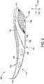
Figure 2 is a medial side view of the shoe sole ofFigure 1 ; -
Figure 3 is a bottom plan view of the shoe sole ofFigure 1 ; -
Figure 4 is a cross-section of the shoe sole ofFigure 1 taken along line 4-4 inFigure 3 ; -
Figure 5 is a cross-section of the shoe sole ofFigure 1 taken along line 5-5 inFigure 3 ; -
Figure 6 is a cross-section of the shoe sole ofFigure 1 taken along line 6-6 inFigure 3 ; -
Figure 7 is a cross-section of the shoe sole ofFigure 1 taken along line 7-7 inFigure 3 ; -
Figure 8 is a top plan view of the shoe sole ofFigure 1 illustrating one embodiment of a reinforcing element suitable for use with the shoe sole ofFigures 1-8 ; -
Figure 9 is a top plan view of another shoe sole illustrating another embodiment of a reinforcing element suitable for use with the shoe sole ofFigures 1-8 ; -
Figure 10 is a top plan view of another shoe sole illustrating another embodiment of a reinforcing element suitable for use with the shoe sole ofFigures 1-8 ; -
Figure 11 is a lateral side view of another embodiment of a shoe sole; -
Figure 12 is a bottom plan view of the shoe sole ofFigure 11 ; -
Figure 13 is a cross-section of the shoe sole ofFigure 11 taken along line 13-13 inFigure 12 ; -
Figure 14 is a lateral side view of another embodiment of a shoe sole; -
Figure 15 is a bottom plan view of the shoe sole ofFigure 14 ; and -
Figure 16 is a cross-section of the shoe sole ofFigure 14 taken along line 16-16 inFigure 15 . - Corresponding reference characters indicate corresponding parts throughout the several views of the drawings.
- Referring to
Figure 1 , an article of footwear shown in the form of a running shoe is indicated generally in its entirety by thereference numeral 20. The article of footwear includes a shoe sole, indicated generally by thereference numeral 100, and a shoe upper 22. Theshoe sole 100 is fixed to the shoe upper 22 by suitable attachment means, such as adhesive bonding, to form the article offootwear 20. The shoe upper 22 is used to secure the article offootwear 20 and the shoe sole 100 to a wearer's foot using suitable fasteners including, for example and without limitation, shoelaces, buckles, straps, hook and loop fasteners, and any other mechanical fasteners that enable the shoe upper 22 and shoe sole 100 to be secured to a wearer's foot. In one embodiment, the shoe upper 22 is constructed from a relatively lightweight, breathable material, such as a mesh material. In other embodiments, the shoe upper 22 may be constructed from materials other than lightweight, breathable materials. - With additional reference to
Figures 2-8 , theshoe sole 100 extends in a walking orlongitudinal direction 102 from aheel region 110, through a metatarsal ormidfoot region 112, to a ball and toe orforefoot region 114. Theheel region 110, themidfoot region 112, and theforefoot region 114 each extend in thelongitudinal direction 102 over approximately one-third of the length of theshoe sole 100. Theheel region 110 adjoins themidfoot region 112, and extends rearward in thelongitudinal direction 102 from themidfoot region 112 to aheel 116 of theshoe sole 100. Theforefoot region 114 adjoins themidfoot region 112, and extends forward in thelongitudinal direction 102 from themidfoot region 112 to atoe 118 of theshoe sole 100. - As shown in
Figures 3 and5-7 , each of theheel region 110, themidfoot region 112, and theforefoot region 114 have a respective width measured in atransverse direction 104 oriented perpendicular to thelongitudinal direction 102. The sole 100 also includes alateral side 120 and amedial side 122 disposed on transversely opposite sides of the sole 100. Thelateral side 120 of the sole 100 generally refers to the outside of the sole 100 that faces outward and away from a wearer when worn on the wearer's foot, and themedial side 122 generally refers to the inner side of the sole 100 that faces towards the wearer's body when worn on the wearer's foot. The thicknesses of the sole 100 and components thereof are measured along avertical direction 106 oriented perpendicular to both thelongitudinal direction 102 and thetransverse direction 104. - As shown in
Figures 1-4 , theshoe sole 100 generally includes amidsole 124 and anoutsole 126. As shown inFigure 4 , themidsole 124 extends from theheel 116 of the sole 100 to thetoe 118 of the sole 100, and includes anupper surface 128 for attachment to at least one of an insole (not shown) and the shoe upper 22 (Figure 1 ), and alower surface 130 disposed opposite theupper surface 128. Theoutsole 126 is disposed along thelower surface 130 of themidsole 124, and extends from theheel region 110 to theforefoot region 114. Theoutsole 126 defines a ground-contactingsurface 140 of the sole 100, and is constructed from a relatively hard, abrasion-resistant material. Suitable materials from which theoutsole 126 may be constructed include, for example and without limitation, hard rubber. In some embodiments, theoutsole 126 is co-molded with thelower surface 130 of themidsole 124 to provide a relatively lightweight construction, and to provide a balance of wear and flexibility. - In the example embodiment, the
midsole 124 has a three-piece construction including aforefoot cushioning element 132, amidfoot cushioning element 134, and aheel cushioning element 136. - The
forefoot cushioning element 132 extends from theforefoot region 114 through themidfoot region 112 to theheel region 110, and defines theupper surface 128 of the midsole. In the example embodiment, theforefoot cushioning element 132 extends the entire length of the shoe sole 100 from theheel 116 to thetoe 118. Theforefoot cushioning element 132 adjoins theoutsole 126 along theforefoot region 114 of the sole 100, and is spaced from theoutsole 126 in themidfoot region 112 andheel region 110. - The
forefoot cushioning element 132 extends a thickness in thevertical direction 106 in theforefoot region 114 from theupper surface 128 of themidsole 124 to the lower surface of themidsole 124. That is, theforefoot cushioning element 132 fills the entire volume of themidsole 124 in theforefoot region 114. Theforefoot cushioning element 132 also includes a thin portion or segment extending from theforefoot region 114 rearward to theheel 116 of the sole 100. - The
midfoot cushioning element 134 is disposed within themidfoot region 112, and adjoins theoutsole 126 along themidfoot region 112. Themidfoot cushioning element 134 is disposed vertically between the forefoot cushioning element 132 (specifically, the rearward extending thin segment) and theoutsole 126, and horizontally between theforefoot cushioning element 132 and theheel cushioning element 136. - The
heel cushioning element 136 is disposed within theheel region 110 of the sole 100 and vertically between theforefoot cushioning element 132 and theoutsole 126. Moreover, theheel cushioning element 136 is disposed vertically between themidfoot cushioning element 134 and theoutsole 126. Theheel cushioning element 136 adjoins each of theforefoot cushioning element 132 and theoutsole 126 in theheel region 110 of the sole 100. - As shown in
Figure 4 , theforefoot cushioning element 132 and theheel cushioning element 136 cooperatively define arecess 138 in themidfoot region 112 of the sole 100. Themidfoot cushioning element 134 is disposed within therecess 138, and vertically and horizontally between theforefoot cushioning element 132 and theheel cushioning element 136. Themidfoot cushioning element 134 adjoins theforefoot cushioning element 132 along an upper surface of themidfoot cushioning element 134, and adjoins theheel cushioning element 136 along a lower surface of themidfoot cushioning element 134. - Each component of the
midsole 124 is constructed from a relatively soft, flexible material as compared to theoutsole 126 to provide a desired amount of damping. Suitable materials from which the components of themidsole 124 may be constructed include, for example and without limitation, polyurethane elastomer foams, open-celled foams, such as open-celled polyurethane foam, ethylene vinyl acetate (EVA), and combinations thereof. In the example embodiment, theforefoot cushioning element 132 and theheel cushioning element 136 are constructed from relatively firm materials as compared to themidfoot cushioning element 134 to provide a low to moderate level of damping and shock absorption. Themidfoot cushioning element 134 is constructed from a relatively soft, elastic, and highly deformable material as compared to theforefoot cushioning element 132 and theheel cushioning element 136 to provide a high amount of damping and shock absorption. Suitable materials from which themidfoot cushioning element 134 may be constructed include, for example and without limitation, open-celled foams, such as open-celled polyurethane foam. Generally, themidfoot cushioning element 134 has a lower density and a lower hardness than each of theforefoot cushioning element 132 and theheel cushioning element 136. - In another embodiment, the
heel cushioning element 136 is constructed from a relatively soft, elastic, and highly deformable material as compared to theforefoot cushioning element 132 and themidfoot cushioning element 134, and is the softest cushioning element in themidsole 124. In such embodiments, theheel cushioning element 136 has a lower density and a lower hardness than each of theforefoot cushioning element 132 and themidfoot cushioning element 134. - In the example embodiment, the
forefoot cushioning element 132, themidfoot cushioning element 134, and theheel cushioning element 136 are each constructed from separate pieces of material, although in other embodiments, two or more of theforefoot cushioning element 132, themidfoot cushioning element 134, and theheel cushioning element 136 may have a monolithic or unitary construction. - As shown in
Figures 1 ,2 , and4 , theshoe sole 100 has a continuously upward convex bottom profile. The bottom profile of theshoe sole 100 is sized and shaped such that animpact region 142 of the sole 100 is defined within themidfoot region 112 of the sole 100. The term "impact region" generally refers to the point or area along the ground-contactingsurface 140 of the shoe sole 100 that initially strikes or contacts a ground surface during running. - The bottom profile of the shoe sole 100 curves generally upward from the
midfoot region 112 to each of theheel region 110 and theforefoot region 114. - In some embodiments, the heel region 110 (specifically, the
outsole 126 within the heel region 110) curves upward from themidfoot region 112 at a first radius ofcurvature 144 of between about 220 millimeters (mm) and about 460 mm, and, more suitably, between about 240 mm and about 350 mm. The forefoot region 114 (specifically, theoutsole 126 within the forefoot region 114) curves upward from themidfoot region 112 at a second radius ofcurvature 146 of between about 220 mm and about 440 mm, and, more suitably, between about 240 mm and about 320 mm. Themidfoot region 112 has a third radius ofcurvature 148 of between about 800 mm and about 1040 mm, and, more suitably, between about 840 mm and about 1000 mm. The radii of curvature of theheel region 110, themidfoot region 112, and theforefoot region 114 may vary depending on the size of the shoe and the intended application of the shoe. In some embodiments, the ratio between the radius of curvature of theheel region 110, themidfoot region 112, and theforefoot region 114 is between about 1.0:2.0:1.0 and about 1.1:3.5:1.0. In other embodiments, theheel region 110, themidfoot region 112, and theforefoot region 114 may have any suitable radii of curvature that enables the shoe sole 100 to function as described herein. In yet other embodiments, the bottom profile of the shoe sole 100 may have a single, continuous radius of curvature extending from theheel region 110, through themidfoot region 112, and into theforefoot region 114. - The bottom profile of the sole 100 results in the
impact region 142 being the lowest point on the shoe sole 100 as measured in thevertical direction 106 when the sole 100 is in an unloaded condition (i.e., at rest) on a flat, reference ground plane (i.e., a plane oriented perpendicular to the vertical direction 106), indicated at 150 inFigure 4 . The condition of the shoe sole 100 illustrated inFigure 4 is also referred to herein as a reference condition. - As shown in
Figure 4 , when theshoe sole 100 is in the reference condition, theheel 116 of the sole 100 is spaced avertical distance 152 above theimpact region 142, and thetoe 118 is spaced avertical distance 154 above theimpact region 142. In some embodiments, thevertical distance 152 between theheel 116 and theimpact region 142 is at least about 15 mm, more suitably, at least about 25 mm, and even more suitably, at least about 35 mm. Further, in some embodiments, thevertical distance 154 between thetoe 118 and theimpact region 142 is at least about 25 mm, more suitably, at least about 45 mm, and even more suitably, at least about 50 mm. - The shoe sole 100 also has a thickness profile that promotes a
midfoot impact region 142. Specifically, the thickness of the sole 100, measured from theupper surface 128 of themidsole 124 to theoutsole 126 along a vertical axis parallel to thevertical direction 106, gradually increases from theheel region 110 to themidfoot region 112, and gradually decreases from themidfoot region 112 to theforefoot region 114. Moreover, in some embodiments (e.g.,Figure 13 ), the thickest portion of the sole 100 is in themidfoot region 112, and is generally aligned with theimpact region 142. That is, the sole 100 has a thickness in themidsole region 112 that is greater than the thickness of the sole 100 in theheel region 110 and theforefoot region 114. The thickness of the sole 100 includes themidsole 124 and theoutsole 126, and is measured from theupper surface 128 of themidsole 124 to the ground-contactingsurface 140 of the sole 100 along the vertical direction 106 (i.e., a direction normal to thelongitudinal direction 102 of the sole 100, and, when in the reference condition (shown inFigure 4 ), normal to the ground or reference plane 150). - In one embodiment, the thickness of the sole 100 in the heel region 110 (specifically, the portion of the sole 100 that sits directly beneath the calcaneus of the foot when the sole is worn on a user's foot) is between about 13 mm and about 23 mm, and, more suitably, between about 16 mm and about 20 mm; the maximum thickness of the sole in the
midfoot region 112 is between about 20 mm and about 30 mm, and, more suitably, between about 22 mm and about 26 mm; and the thickness of the sole 100 in theforefoot region 114 is between about 13 mm and about 23 mm, and, more suitably, between about 16 mm and about 20 mm. - In another embodiment, the thickness of the sole 100 in the heel region 110 (specifically, the portion of the sole 100 that sits directly beneath the calcaneus of the foot when the sole is worn on a user's foot) is between about 27 mm and about 37 mm, and, more suitably, between about 30 mm and about 34 mm; the maximum thickness of the sole in the
midfoot region 112 is between about 26 mm and about 36 mm, and, more suitably, between about 28 mm and about 32 mm; and the thickness of the sole 100 in theforefoot region 114 is between about 15 mm and about 25 mm, and, more suitably, between about 17 mm and about 23 mm. - In yet another embodiment, the thickness of the sole 100 in the heel region 110 (specifically, the portion of the sole 100 that sits directly beneath the calcaneus of the foot when the sole is worn on a user's foot) is between about 31 mm and about 42 mm, and, more suitably, between about 33 mm and about 39 mm; the maximum thickness of the sole in the
midfoot region 112 is between about 33 mm and about 44 mm, and, more suitably, between about 36 mm and about 41 mm; and the thickness of the sole 100 in theforefoot region 114 is between about 22 mm and about 32 mm, and, more suitably, between about 24 mm and about 30 mm. In one particular embodiment, themidfoot region 112 is between about 1 mm and about 4 mm thicker than the heel region 110 (specifically, the portion of the sole 100 that sits directly beneath the calcaneus of the foot when the sole is worn on a user's foot). - The exact thickness of the sole 100 in the
heel region 110, themidfoot region 112, and theforefoot region 114 may vary depending on the size of the shoe and the intended application of the shoe. In some embodiments, the ratio between the thickness of the sole 100 in theheel region 110, themidfoot region 112, and theforefoot region 114 is between about 1.0:1.1:1.0 and about 1.0:1.7:1.0. In other embodiments, the ratio between the thickness of the sole 100 in theheel region 110, themidfoot region 112, and theforefoot region 114 is between about 1.3:1.3:1.0 and about 1.7:1.6:1.0. In yet other embodiments, the ratio between the thickness of the sole 100 in theheel region 110, themidfoot region 112, and theforefoot region 114 is between about 1.2:1.25:1.0 and about 1.4:1.5:1.0. - The bottom profile of the
shoe sole 100 and, more specifically, the curvature and thickness profile of theshoe sole 100, promote a midfoot impact region. As described in more detail herein, components of the shoe sole 100 are designed to provide optimal cushioning and shock absorption, as well as promote a dynamic, rolling action during running, based on theimpact region 142 being located in themidfoot region 112 of the sole 100. - The
outsole 126 has a relatively stiffer construction along themidfoot region 112 to form apivot axis 156 about which theheel region 110 and theforefoot region 114 pivot during use. In particular, theoutsole 126 is relatively stiffer along thepivot axis 156 as compared to portions of theoutsole 126 forward and rearward of thepivot axis 156 to provide a rigid area about which the sole 100 can pivot. Theoutsole 126 may be constructed from a relatively stiffer material and/or include stiffening elements, such as fibers, along thepivot axis 156 to provide an increased stiffness along thepivot axis 156. Thepivot axis 156 is oriented substantially parallel to thetransverse direction 104, and substantially perpendicular to thelongitudinal direction 102. - As shown in
Figure 4 , thepivot axis 156 is within theimpact region 142 of the sole 100, and thereby facilitates a continuous gait roll from the initial point of impact to toe-off, and promotes active rolling with each step. In the example embodiment, thepivot axis 156 is located along the middle third of shoe sole 100 in thelongitudinal direction 102, and, more specifically, is located at a longitudinal distance of about 40% to about 60% of the length of the shoe sole 100 from theheel 116. - The
midfoot cushioning element 134 is configured to provide optimal impact absorption during running and to return energy to the user's foot as the user's weight shifts from themidfoot region 112 to theforefoot region 114. In particular, themidfoot cushioning element 134 is disposed within themidfoot region 112, and directly above (i.e., immediately adjacent to and vertically above) theimpact region 142 andpivot axis 156. Moreover, themidfoot cushioning element 134 adjoins theoutsole 126 along theimpact region 142 of the sole such that themidfoot cushioning element 134 absorbs energy from an initial impact of the sole 100 along theimpact region 142, and transfers energy to a user's foot upon the sole 100 pivoting about thepivot axis 156. Additionally, themidfoot cushioning element 134 has a thickness measured in thevertical direction 106 that gradually increases from theheel region 110 to a maximum thickness in themidfoot region 112. Themidfoot cushioning element 134 thereby provides some cushioning and shock absorption in theheel region 110, while providing a majority of cushioning and shock absorption along themidfoot region 112 andimpact region 142. Further, as shown inFigures 6 and7 , themidfoot cushioning element 134 extends in thetransverse direction 104 from thelateral side 120 to themedial side 122 to provide cushioning and shock absorption across the entire width of the sole 100. - As noted above, the
midsole 124 of the illustrated embodiment has a three-piece construction, including theforefoot cushioning element 132, themidfoot cushioning element 134, and theheel cushioning element 136. In some embodiments, theforefoot cushioning element 132, themidfoot cushioning element 134, and theheel cushioning element 136 have different hardness values to provide a desired hardness distribution or profile along thelongitudinal direction 102 of the sole 100. In the example embodiment, the sole 100 has a tri-hardness configuration along thelongitudinal direction 102 of the sole 100 that promotes a dynamic, rolling action during running, and also facilitates optimal shock absorption and energy transfer. In particular, theforefoot cushioning element 132, theheel cushioning element 136, and themidfoot cushioning element 134 have different hardness values such that theforefoot region 114 of the sole 100 has a first hardness, theheel region 110 has a second hardness less than the first hardness, and themidfoot region 112 has a third hardness that is less than both the first hardness and the second hardness. In another suitable embodiment, theforefoot cushioning element 132, theheel cushioning element 136, and themidfoot cushioning element 134 have different hardness values such that the hardness of the heel region 110 (i.e., the second hardness) is less than both the hardness of the forefoot region 114 (i.e., the first hardness) and the hardness of the midfoot region 112 (i.e., the third hardness), and the hardness of themidfoot region 112 is less than the hardness of theforefoot region 114. - In some embodiments, the
forefoot cushioning element 132 has the first hardness, theheel cushioning element 136 has the second hardness, and themidfoot cushioning element 134 has the third hardness. In other embodiments, theforefoot cushioning element 132, theheel cushioning element 136, and themidfoot cushioning element 134 have different hardness values such that the resulting combination of hardness values in theforefoot region 114, themidfoot region 112, and theheel region 110 are the first hardness, the second hardness, and the third hardness, respectively. - In some embodiments, the ratio between the first hardness value in the
forefoot region 114, the second hardness value in theheel region 110, and the third hardness value in themidfoot region 112 is between about 1.0:1.0:1.0 and about 2.0:1.75:1.0, and, more suitably, between about 1.2:1.1:1.0 and about 1.6:1.4:1.0. In one particular embodiment, the ratio between the first hardness value in theforefoot region 114, the second hardness value in theheel region 110, and the third hardness value in themidfoot region 112 is about 1.22:1.11:1.0. In another particular embodiment, the ratio between the first hardness value in theforefoot region 114, the second hardness value in theheel region 110, and the third hardness value in themidfoot region 112 is about 1.33:1.11:1.0. - In some embodiments, the forefoot region 114 (specifically, the forefoot cushioning element 132) has a hardness of between about 50 and 70 as measured on the Asker Type C hardness scale (hereinafter "Asker C"), and, more suitably between about 50 and 65 Asker C; the heel region 110 (specifically, the heel cushioning element 136) has a hardness of between about 40 and 60 Asker C, and, more suitably, between about 45 and 55 Asker C; and the midfoot region 112 (specifically, the midfoot cushioning element 134) has a hardness of between about 35 and 55 Asker C, and, more suitably, between about 40 and 50 Asker C. In one particular embodiment, the
forefoot region 114 has a hardness of about 55 Asker C, theheel region 110 has a hardness of about 50 Asker C, and themidfoot region 112 has a hardness of about 45 Asker C. In another particular embodiment, theforefoot region 114 has a hardness of about 60 Asker C, theheel region 110 has a hardness of about 50 Asker C, and themidfoot region 112 has a hardness of about 45 Asker C. - As shown in
Figure 8 , theshoe sole 100 of the illustrated embodiment also includes a reinforcingelement 160 embedded within the midsole 124 (specifically, the forefoot cushioning element 132). The reinforcingelement 160 is constructed from suitably rigid, elastic materials that provide both flexibility and structural support (i.e., rigidity) within themidsole 124. Suitable materials from which 160 the reinforcingelement 160 may be constructed include, for example and without limitation, fiber-reinforced ethylene-vinyl acetate (EVA), carbon-fiber composites, fiber-reinforced polyurethane elastomers (TPU), glass-reinforced composites, nylon, and combinations thereof. The reinforcingelement 160 may be embedded in themidsole 124, for example, by molding themidsole 124 around the reinforcing element. - In the embodiment illustrated in
Figure 8 , the reinforcingelement 160 has a generally u-shaped cross-section, and includes afirst prong 162 and asecond prong 164 connected to one another in theheel region 110 of the sole 100. Each of thefirst prong 162 and thesecond prong 164 extend in thelongitudinal direction 102 from theheel region 110 to at least themidfoot region 112 to provide stiffness in thelongitudinal direction 102. In the embodiment illustrated inFigure 8 , each of thefirst prong 162 and thesecond prong 164 extend in thelongitudinal direction 102 from theheel region 110, through themidfoot region 112 and into theforefoot region 114. -
Figure 9 is a top plan view of another shoe sole 900 illustrating another embodiment of a reinforcingelement 902 suitable for use in theshoe sole 100 ofFigures 1-8 . The reinforcingelement 902 shown inFigure 9 is substantially similar to the reinforcingelement 160 shown inFigure 8 , except the reinforcingelement 902 includescross-members 904 providing stiffness in thetransverse direction 104. Accordingly, like elements are labeled with like reference numerals. As shown inFigure 9 , the reinforcingelement 902 includescross-members 904 extending between and interconnecting thefirst prong 162 and thesecond prong 164. The illustrated reinforcingelement 902 includes threecross-members 904, although other embodiments may include more than or less than three cross-members 904. One of the cross-members 904 is disposed in aheel region 910 of the sole 900, one of the cross-members 904 is disposed in amidfoot region 912 of the sole 900, and one of the cross-members 904 is disposed in aforefoot region 914 of the sole 900. The cross-members 904 located in theheel region 910 and themidfoot region 912 each extend in a direction parallel to thetransverse direction 104, and thus provide additional stiffness in thetransverse direction 104 in theheel region 910 and themidfoot region 912. The cross-member 904 located in theforefoot region 914 extends at an oblique angle of between about 25 degrees and about 40 degrees with respect to thetransverse direction 104, and thus provides additional stiffness in both thelongitudinal direction 102 and thetransverse direction 104 in theforefoot region 914. The reinforcingelement 902 shown inFigure 9 is particularly well suited for use in a shoe sole having relatively soft heel and midfoot regions, such as the shoe sole 100 shown inFigures 1-8 . -
Figure 10 is a top plan view of a shoe sole 1000 illustrating another embodiment of a reinforcingelement 1002 suitable for use in theshoe sole 100 ofFigures 1-8 . In the embodiment illustrated inFigure 10 , the reinforcingelement 1002 includes afirst prong 1004 and asecond prong 1006 connected to one another by au-shaped connector 1008 in aheel region 1010 of the sole 1000. Each of thefirst prong 1004 and thesecond prong 1006 extend in thelongitudinal direction 102 from theheel region 1010 to amidfoot region 1012, but do not extend into aforefoot region 1014 of the sole 1000. - The
first prong 1004 is shaped complementary to amedial side 1016 of the sole 1000, and thesecond prong 1006 is shaped complementary to alateral side 1018 of the sole 1000. Thefirst prong 1004 and thesecond prong 1006 are spaced transversely inward from respective medial andlateral sides - The reinforcing
element 1002 also includes a plurality of cross-members 1020 extending between and interconnecting thefirst prong 1004 and thesecond prong 1006. The illustrated embodiment includes four cross-members 1020, although other embodiments may include more than or less than four cross-members 1020. In the embodiment illustrated inFigure 10 , two of the cross-members 1020 extend at an oblique angle with respect to thetransverse direction 104, and intersect one another approximately midway between thefirst prong 1004 and thesecond prong 1006. - The reinforcing
element 1002 also includes forward projectingmembers 1022 that extend forward in thelongitudinal direction 102 from the cross-member 1020 located at the front of thefirst prong 1004 and thesecond prong 1006. Theforward projecting members 1022 are spaced transversely inward from respective medial andlateral sides first prong 1004 and thesecond prong 1006. Theforward projecting members 1022 thereby provide flexibility in thelongitudinal direction 102 along transversely outward portions of the sole 1000 in theforefoot region 1014. - The reinforcing
element 1002 also includesforefoot cross-members 1024 located in theforefoot region 1014. Each of theforefoot cross-members 1024 extend across both of theforward projecting members 1022, and beyond the forward projectingmembers 1022 in thetransverse direction 104. Theforefoot cross-members 1024 thereby provide stiffness in thetransverse direction 104 along transversely outward portions of the sole 1000 in theforefoot region 1014. The illustrated embodiment includes threeforefoot cross-members 1024, although other embodiments may include more than or less than threeforefoot cross-members 1024. -
Figures 11-13 are various views of another suitable embodiment of a shoe sole 1100 having a midfoot impact region. Theshoe sole 1100 is substantially identical to the shoe sole 100 shown inFigures 1-8 , except for dimensional variations. Accordingly, like elements are labeled with like reference numerals. - The shoe sole 1100 illustrated in
Figures 11-13 has a more pronouncedmidfoot region 112 as compared to the sole 100 ofFigures 1-8 . For example, the heel region 110 (specifically, theoutsole 126 within the heel region 110) of the shoe sole 1100 curves upward from themidfoot region 112 at a first radius ofcurvature 144 less than the first radius ofcurvature 144 of theshoe sole 100 ofFigures 1-8 , and the forefoot region 114 (specifically, theoutsole 126 within the forefoot region 114) curves upward from themidfoot region 112 at a second radius ofcurvature 146 less than the second radius ofcurvature 146 of theshoe sole 100 ofFigures 1-8 . - Additionally, in the embodiment illustrated in
Figures 11-13 , the thickness of the sole 1100 in theheel region 110 is between about 17 mm and about 27 mm, and, more suitably, between about 20 mm and about 24 mm. The maximum thickness of the sole 1100 in themidfoot region 112 is between about 33 mm and about 44 mm, and, more suitably, between about 36 mm and about 41 mm. The thickness of the sole 1100 in theforefoot region 114 is between about 10 mm and about 20 mm, and, more suitably, between about 13 mm and about 17 mm. The ratio between the thickness of the sole 1100 in theheel region 110, themidfoot region 112, and theforefoot region 114 is between about 1.4:2.5:1.0 and about 1.5:2.6:1.0. -
Figures 14-16 are various views of another suitable embodiment of a shoe sole 1400 having a midfoot impact region. Theshoe sole 1400 extends in a walking orlongitudinal direction 1402 from aheel region 1410, through amidfoot region 1412, to aforefoot region 1414 . - The shoe sole 1400 illustrated in
Figures 14-16 includes amidsole 1416 and anoutsole 1418. As shown inFigure 16 , themidsole 1416 includes anupper surface 1420 for attachment to at least one of an insole and a shoe upper, and alower surface 1422 disposed opposite theupper surface 1420. Theoutsole 1418 is disposed along thelower surface 1422 of themidsole 1416, and extends from theheel region 1410 to theforefoot region 1414. - In the embodiment illustrated in
Figures 14-16 , themidsole 1416 has a unitary construction. That is, themidsole 1416 of theshoe sole 1400 is not formed from separate parts or components. Moreover, in the embodiment illustrated inFigures 14-16 , themidsole 1416 does not include a separate cushioning element. That is, themidsole 1416 is free of separate cushioning elements, although themidsole 1416 may act as a cushioning element depending on the hardness of themidsole 1416. - Similar to the shoe sole of
Figures 1-8 , theshoe sole 1400 has a continuously upward convex bottom profile such that animpact region 1424 of the sole 1400 is defined within themidfoot region 1412 of the sole 1400. - In the embodiment illustrated in
Figures 14-16 , the heel region 1410 (specifically, theoutsole 1418 within the heel region 1410) curves upward from themidfoot region 1412 at a first radius ofcurvature 1426 of between about 390 mm and about 450 mm, the forefoot region 1414 (specifically, theoutsole 1418 within the forefoot region 1414) curves upward from themidfoot region 1412 at a second radius ofcurvature 1428 of between about 360 mm and about 420 mm, and themidfoot region 1412 has a third radius ofcurvature 1430 of between about 970 mm and about 1030 mm. - Additionally, the
outsole 1418 has a relatively stiffer construction along themidfoot region 1412 to form apivot axis 1432 about which theheel region 1410 and theforefoot region 1414 pivot during use. In particular, theoutsole 1418 is relatively stiffer along thepivot axis 1432 as compared to portions of theoutsole 1418 forward and rearward of thepivot axis 1432 to provide a rigid area about which the sole 1400 can pivot. Theoutsole 1418 may be constructed from a relatively stiffer material and/or include stiffening elements, such as fibers, along thepivot axis 1432 to provide an increased stiffness along thepivot axis 1432. Thepivot axis 1432 is oriented substantially parallel to atransverse direction 1404 of the sole 1400 (Figure 15 ), and substantially perpendicular to thelongitudinal direction 1402. As shown inFigure 16 , thepivot axis 1432 is within theimpact region 1424 of the sole 1400, and thereby facilitates a continuous gait roll from the initial point of impact to toe-off, and promotes active rolling with each step. - Embodiments of the shoe soles described are particularly well suited for running, and provide several advantages over known running shoe soles. For example, embodiments of the shoes soles described herein have a bottom profile that is contoured and shaped to promote an impact or strike point along the midfoot region of the sole, rather than the heel region. Moreover, the shoe soles described herein are generally convex, and curve upward from the midfoot region to each of the heel and forefoot regions. The shoe soles thereby promote a dynamic, rolling action during running as a user's weight shifts from the heel region to the forefoot region. Additionally, the shoe soles described herein include a midfoot pivot axis disposed along the impact region of the sole, thereby promoting a continuous gait roll from the initial strike or impact point to toe-off. Moreover, the shoe soles described herein include a relatively thick cushioning element arranged in the midfoot region of the sole directly above the impact region of the sole. The shoe soles thereby provide enhanced cushioning and a soft landing with excellent shock absorption during midfoot strike as compared to running shoes having an impact region or cushioning element in the heel region of the sole. Further, the shoe soles described herein also have a three-piece construction and provide a tri-hardness configuration that promotes a dynamic, rolling action during running, and also facilitates optimal shock absorption and energy transfer.
- When introducing elements of the present invention or the embodiment(s) thereof, the articles "a", "an", "the" and "said" are intended to mean that there are one or more of the elements. The terms "comprising", "including" and "having" are intended to be inclusive and mean that there may be additional elements other than the listed elements.
Claims (15)
- A shoe sole (100) for an article of footwear (20), the sole extending in a longitudinal direction from a heel region (110), through a midfoot region (112), to a forefoot region (114), the sole comprising:a midsole having an upper surface for attachment to at least one of an insole and a shoe upper (22), and a lower surface (130) disposed opposite the upper surface, the midsole including a forefoot cushioning element (132), a midfoot cushioning element (134), and a heel cushioning element (134), the forefoot cushioning element and the heel cushioning element cooperatively defining a recess in the midfoot region of the shoe sole; andan outsole (126) disposed along the lower surface of the midsole and defining a ground-contacting surface of the sole;wherein the sole has an upwardly convex bottom profile such that an impact region of the sole is defined within the midfoot region, the midfoot cushioning element disposed within the recess, vertically and horizontally between the forefoot cushioning element and the heel cushioning element, and directly above the impact region of the sole.
- The shoe sole of claim 1, wherein the outsole has a relatively stiff construction along the midfoot region thereby forming a pivot axis (156) within the impact region about which the heel region and the forefoot region pivot, the midfoot cushioning element disposed directly above the pivot axis.
- The shoe sole of claim 2, wherein the midfoot cushioning element adjoins the outsole along the impact region of the sole, whereby the midfoot cushioning element is configured to absorb energy from an initial impact of the sole along the impact region and transfer energy to a user's foot upon the sole pivoting about the pivot axis.
- The shoe sole of any one of claims 1-3, wherein the forefoot cushioning element extends a thickness in the forefoot region from the upper surface of the midsole to the lower surface of the midsole, the forefoot cushioning element adjoining the outsole along the forefoot region of the sole and extending from the forefoot region to the heel region, wherein the heel cushioning element is disposed vertically between the forefoot cushioning element and the outsole, the heel cushioning element adjoining each of the forefoot cushioning element and the outsole in the heel region of the sole.
- The shoe sole of any one of claims 1-3, wherein the midfoot cushioning element has a hardness less than a hardness of each of the forefoot cushioning element and the heel cushioning element.
- The shoe sole of claim 5, wherein the forefoot cushioning element has a first hardness, the heel cushioning element has a second hardness less than the first hardnesss, and the midfoot cushioning element has a third hardness, the second hardness greater than the third hardness.
- The shoe sole of any one of claims 1-3, wherein the forefoot cushioning element has a first hardness, the heel cushioning element has a second hardness, and the midfoot cushioning element has a third hardness, wherein the first hardness is greater than the third hardness, and wherein the second hardness is less than both the first hardness and the third hardness.
- The shoe sole of any one of claims 1-3, wherein the shoe sole includes a lateral side (120) and an opposing medial side (122), the midfoot cushioning element extending from the lateral side to the medial side.
- The shoe sole of any one of claims 1-3, further comprising a reinforcing element (160) embedded in the midsole, the reinforcing element (160) being generally u-shaped and including a first prong (162, 1004) and a second prong (164, 1006) connected to one another in the heel region of the sole, each of the first prong and the second prong extending in the longitudinal direction from the heel region to at least the midfoot region to provide stiffness in the longitudinal direction.
- An article of footwear comprising the shoe sole of any one of claims 1-3 and an upper secured to the midsole.
- The shoe sole of any one of claims 1-3, 4, 8, 9 wherein-the midsole has a first hardness in the forefoot region, a second hardness in the heel region less than the first hardness, and a third hardness in the midfoot region above the impact region less than both the first hardness and the second hardness.
- The shoe sole of claim 11, wherein the forefoot cushioning element has the first hardness, the heel cushioning element has the second hardness, and the midfoot cushioning element has the third hardness, wherein the forefoot cushioning element extends from the forefoot region to the heel region.
- The shoe sole of claim 12, wherein the forefoot cushioning element has the first hardness, the heel cushioning element has the second hardness, and the midfoot cushioning element has the third hardness, and wherein the midfoot cushioning element has a hardness of between about 35 Asker C and about 55 Asker C.
- The shoe sole of any one of claims 11 - 14, wherein a ratio between the first hardness, the second hardness, and the third hardness is between about 1.0:1.0:1.0 and about 2.0:1.75:1.0.
- The shoe sole of claim 14, wherein the ratio between the first hardness, the second hardness, and the third hardness is between about 1.2:1.1:1.0 and about 1.6:1.4:1.0.
Applications Claiming Priority (2)
| Application Number | Priority Date | Filing Date | Title |
|---|---|---|---|
| US14/724,973 US20160345668A1 (en) | 2015-05-29 | 2015-05-29 | Articles of footwear and shoe soles for midfoot impact region |
| PCT/US2015/033709 WO2016195661A1 (en) | 2015-05-29 | 2015-06-02 | Articles of footwear and shoe soles for midfoot impact region |
Publications (2)
| Publication Number | Publication Date |
|---|---|
| EP3302142A1 EP3302142A1 (en) | 2018-04-11 |
| EP3302142B1 true EP3302142B1 (en) | 2019-10-02 |
Family
ID=53783288
Family Applications (1)
| Application Number | Title | Priority Date | Filing Date |
|---|---|---|---|
| EP15745590.8A Active EP3302142B1 (en) | 2015-05-29 | 2015-06-02 | Shoe soles for midfoot impact region |
Country Status (15)
| Country | Link |
|---|---|
| US (1) | US20160345668A1 (en) |
| EP (1) | EP3302142B1 (en) |
| JP (1) | JP6751139B2 (en) |
| KR (1) | KR20180015165A (en) |
| CN (1) | CN108135321A (en) |
| AU (1) | AU2015397192A1 (en) |
| BR (1) | BR112017025431A2 (en) |
| CA (1) | CA2987391A1 (en) |
| DK (1) | DK3302142T3 (en) |
| ES (1) | ES2760012T3 (en) |
| HK (1) | HK1256585A1 (en) |
| IL (1) | IL255704A (en) |
| RU (1) | RU2017145598A (en) |
| TW (1) | TW201711586A (en) |
| WO (1) | WO2016195661A1 (en) |
Families Citing this family (25)
| Publication number | Priority date | Publication date | Assignee | Title |
|---|---|---|---|---|
| IT201700075302A1 (en) * | 2017-07-05 | 2019-01-05 | U Invest S R L | ENERGIZING SAFETY SHOE. |
| US10149513B1 (en) * | 2018-01-31 | 2018-12-11 | Nike, Inc. | Sole structure for article of footwear |
| US11452334B2 (en) | 2018-01-31 | 2022-09-27 | Nike, Inc. | Airbag for article of footwear |
| IT201800003863A1 (en) * | 2018-03-22 | 2019-09-22 | Pietro Galifi | DEVICE FOR DETERMINING MOVEMENT IN VIRTUAL OR REAL SPACES. |
| US11026476B2 (en) | 2018-07-17 | 2021-06-08 | Nike, Inc. | Airbag for article of footwear |
| US10524540B1 (en) | 2018-07-17 | 2020-01-07 | Nike, Inc. | Airbag for article of footwear |
| FR3087096B1 (en) * | 2018-10-15 | 2020-10-23 | Jet Green | FOOTWEAR ADVANTAGEALLY INTENDED FOR THE PRACTICE OF PHYSICAL ACTIVITIES |
| BR112021000401B1 (en) * | 2018-12-28 | 2023-01-24 | Asics Corporation | SHOE AND SHOE SOLE |
| EP3905915B1 (en) * | 2018-12-31 | 2023-07-05 | NIKE Innovate C.V. | Sole structure having differing hardness regions |
| WO2020163531A1 (en) * | 2019-02-06 | 2020-08-13 | Fuerst Group, Inc. | Footwear article for walking |
| US12279669B2 (en) | 2019-02-06 | 2025-04-22 | Keen, Inc. | Footwear article for walking |
| US11490679B2 (en) * | 2019-09-25 | 2022-11-08 | Nike, Inc. | Foot support components for articles of footwear |
| US11297897B2 (en) * | 2019-11-27 | 2022-04-12 | Cole Haan Llc | Shoe with multiple material sole |
| NO346239B1 (en) * | 2019-12-06 | 2022-05-02 | Gaitline As | Shoe with sole providing a dynamic foot arch support |
| US12317951B2 (en) | 2020-01-03 | 2025-06-03 | Nike, Inc. | Sole structure for article of footwear |
| JP7330237B2 (en) * | 2020-07-23 | 2023-08-21 | プーマ エス イー | Sole structures, footwear devices and assemblies |
| WO2023277146A1 (en) * | 2021-07-01 | 2023-01-05 | 株式会社タイカ | Shoe cushion structure, and shoes and shoe insole provided with same |
| JP7428691B2 (en) * | 2021-12-27 | 2024-02-06 | 美津濃株式会社 | shoe sole |
| US12102170B2 (en) * | 2022-02-25 | 2024-10-01 | Acushnet Company | Article of footwear with midsole having variable stiffness |
| US12102175B2 (en) * | 2022-02-28 | 2024-10-01 | Puma SE | Article of footwear having a sole plate with spikes |
| JP7654616B2 (en) * | 2022-11-18 | 2025-04-01 | 美津濃株式会社 | Shoe sole |
| US20240268519A1 (en) * | 2023-02-13 | 2024-08-15 | Xelero Technology, LLC | Footwear Sole Assembly |
| NL2034893B1 (en) | 2023-05-23 | 2024-12-05 | Bv Nimco Schoenfabriek J Verschuur & Co | Balance footwear with shank. |
| US20250040655A1 (en) * | 2023-08-01 | 2025-02-06 | Nike, Inc. | Sole structure for article of footwear |
| JP7779891B2 (en) * | 2023-10-20 | 2025-12-03 | 美津濃株式会社 | Shoe soles |
Family Cites Families (20)
| Publication number | Priority date | Publication date | Assignee | Title |
|---|---|---|---|---|
| US2810213A (en) * | 1956-05-17 | 1957-10-22 | Jerry J Jonas | Footgear |
| JPS60156403A (en) * | 1983-09-12 | 1985-08-16 | 株式会社アシックス | footwear sole |
| DK0999764T3 (en) | 1997-07-17 | 2003-08-25 | Negort Ag | Shoe |
| UA66877C2 (en) * | 1999-08-28 | 2004-06-15 | Негорт Аг | Footwear for a dynamic rolling walking |
| US6684532B2 (en) * | 2001-11-21 | 2004-02-03 | Nike, Inc. | Footwear with removable foot-supporting member |
| US8146272B2 (en) * | 2008-05-30 | 2012-04-03 | Nike, Inc. | Outsole having grooves forming discrete lugs |
| JP2008523882A (en) * | 2004-12-15 | 2008-07-10 | リー,ホ−ヒュン | Midsole to be worn on the sports shoes |
| US7665229B2 (en) * | 2006-03-31 | 2010-02-23 | Converse Inc. | Foot-supporting structures for articles of footwear and other foot-receiving devices |
| WO2009061103A1 (en) * | 2007-11-08 | 2009-05-14 | Ryn Korea. Co., Ltd. | Masai walking footwear |
| HUP0800101A2 (en) * | 2008-02-18 | 2011-11-28 | Laszlo Solymosi | Shoes with unstable sole construction |
| SI2105058T1 (en) * | 2008-03-29 | 2012-04-30 | Masai Marketing & Trading Ag | Walking device |
| JP5394806B2 (en) * | 2009-04-17 | 2014-01-22 | アキレス株式会社 | Sole structure |
| JP5761899B2 (en) * | 2009-04-17 | 2015-08-12 | 吉岡 好三 | Footwear with a walking promotion effect |
| US20100299969A1 (en) * | 2009-05-29 | 2010-12-02 | Liliana Paez | Layered footwear assembly with an arcuate undersurface |
| EP2305057A1 (en) * | 2009-10-02 | 2011-04-06 | Masai Marketing & Trading AG | Walker base |
| ITTV20090208A1 (en) * | 2009-10-22 | 2011-04-23 | A C Studio S N C Di Armando Ciett O & C | INTERSULATION STRUCTURE, PARTICULARLY FOR FOOTWEAR. |
| EP2361520A1 (en) * | 2010-02-23 | 2011-08-31 | Masai Marketing & Trading AG | Shoe sole with air circulation |
| US9204680B2 (en) * | 2011-11-18 | 2015-12-08 | Nike, Inc. | Footwear having corresponding outsole and midsole shapes |
| CN104918509A (en) * | 2012-08-31 | 2015-09-16 | 斯彭科医疗公司 | Basketball insole |
| US9516919B2 (en) * | 2014-09-16 | 2016-12-13 | Nike, Inc. | Sole structure with bladder for article of footwear and method of manufacturing the same |
-
2015
- 2015-05-29 US US14/724,973 patent/US20160345668A1/en not_active Abandoned
- 2015-06-02 BR BR112017025431A patent/BR112017025431A2/en not_active Application Discontinuation
- 2015-06-02 DK DK15745590.8T patent/DK3302142T3/en active
- 2015-06-02 KR KR1020177036988A patent/KR20180015165A/en not_active Withdrawn
- 2015-06-02 RU RU2017145598A patent/RU2017145598A/en unknown
- 2015-06-02 EP EP15745590.8A patent/EP3302142B1/en active Active
- 2015-06-02 HK HK18115691.0A patent/HK1256585A1/en unknown
- 2015-06-02 CA CA2987391A patent/CA2987391A1/en not_active Abandoned
- 2015-06-02 JP JP2018514772A patent/JP6751139B2/en not_active Expired - Fee Related
- 2015-06-02 CN CN201580082043.1A patent/CN108135321A/en active Pending
- 2015-06-02 ES ES15745590T patent/ES2760012T3/en active Active
- 2015-06-02 AU AU2015397192A patent/AU2015397192A1/en not_active Abandoned
- 2015-06-02 WO PCT/US2015/033709 patent/WO2016195661A1/en not_active Ceased
-
2016
- 2016-05-27 TW TW105116737A patent/TW201711586A/en unknown
-
2017
- 2017-11-15 IL IL255704A patent/IL255704A/en unknown
Non-Patent Citations (1)
| Title |
|---|
| None * |
Also Published As
| Publication number | Publication date |
|---|---|
| CA2987391A1 (en) | 2016-12-08 |
| KR20180015165A (en) | 2018-02-12 |
| RU2017145598A (en) | 2019-07-02 |
| US20160345668A1 (en) | 2016-12-01 |
| AU2015397192A1 (en) | 2017-12-07 |
| HK1256585A1 (en) | 2019-09-27 |
| BR112017025431A2 (en) | 2018-08-07 |
| IL255704A (en) | 2018-01-31 |
| CN108135321A (en) | 2018-06-08 |
| EP3302142A1 (en) | 2018-04-11 |
| ES2760012T3 (en) | 2020-05-12 |
| TW201711586A (en) | 2017-04-01 |
| DK3302142T3 (en) | 2020-01-02 |
| WO2016195661A1 (en) | 2016-12-08 |
| JP2018516733A (en) | 2018-06-28 |
| JP6751139B2 (en) | 2020-09-02 |
Similar Documents
| Publication | Publication Date | Title |
|---|---|---|
| EP3302142B1 (en) | Shoe soles for midfoot impact region | |
| US11622601B2 (en) | Footwear with flexible cage and wedge | |
| EP3412255B1 (en) | Sole assembly for article of footwear with plural cushioning members | |
| US10492564B1 (en) | Footwear construction | |
| US10470521B2 (en) | Sole structure for shoes and shoe with the sole structure | |
| US4542598A (en) | Athletic type shoe for tennis and other court games | |
| US9210967B2 (en) | Sole structure with traction elements | |
| RU2489069C2 (en) | Sole for low shoe, in particular - training shoe | |
| US11825903B2 (en) | Shoe sole and shoe | |
| US20150351492A1 (en) | Article of Footwear | |
| CN112770646B (en) | Footwear with molded sole | |
| US20010032400A1 (en) | Footwear outsole having arcuate inner-structure | |
| JP2021053376A (en) | Sole element | |
| RU2524894C2 (en) | Health footwear and method of its manufacturing | |
| US20170143074A1 (en) | High-heel shank and high-heeled shoes using same | |
| US12201181B2 (en) | Shoe sole and shoe | |
| KR100979261B1 (en) | A running shoes for sports | |
| CN120859245A (en) | Sole of running shoes | |
| IE55374B1 (en) | Athletic type shoe for tennis and other court games |
Legal Events
| Date | Code | Title | Description |
|---|---|---|---|
| STAA | Information on the status of an ep patent application or granted ep patent |
Free format text: STATUS: THE INTERNATIONAL PUBLICATION HAS BEEN MADE |
|
| PUAI | Public reference made under article 153(3) epc to a published international application that has entered the european phase |
Free format text: ORIGINAL CODE: 0009012 |
|
| STAA | Information on the status of an ep patent application or granted ep patent |
Free format text: STATUS: REQUEST FOR EXAMINATION WAS MADE |
|
| 17P | Request for examination filed |
Effective date: 20171129 |
|
| AK | Designated contracting states |
Kind code of ref document: A1 Designated state(s): AL AT BE BG CH CY CZ DE DK EE ES FI FR GB GR HR HU IE IS IT LI LT LU LV MC MK MT NL NO PL PT RO RS SE SI SK SM TR |
|
| AX | Request for extension of the european patent |
Extension state: BA ME |
|
| STAA | Information on the status of an ep patent application or granted ep patent |
Free format text: STATUS: EXAMINATION IS IN PROGRESS |
|
| 17Q | First examination report despatched |
Effective date: 20181220 |
|
| GRAP | Despatch of communication of intention to grant a patent |
Free format text: ORIGINAL CODE: EPIDOSNIGR1 |
|
| STAA | Information on the status of an ep patent application or granted ep patent |
Free format text: STATUS: GRANT OF PATENT IS INTENDED |
|
| RAP1 | Party data changed (applicant data changed or rights of an application transferred) |
Owner name: MASAI INTERNATIONAL PTE LTD. |
|
| RIN1 | Information on inventor provided before grant (corrected) |
Inventor name: SMOTRYCZ, ZENON Inventor name: SING, ANDY CHAW CHONG Inventor name: DYER, ROBERT |
|
| INTG | Intention to grant announced |
Effective date: 20190409 |
|
| GRAS | Grant fee paid |
Free format text: ORIGINAL CODE: EPIDOSNIGR3 |
|
| GRAA | (expected) grant |
Free format text: ORIGINAL CODE: 0009210 |
|
| STAA | Information on the status of an ep patent application or granted ep patent |
Free format text: STATUS: THE PATENT HAS BEEN GRANTED |
|
| AK | Designated contracting states |
Kind code of ref document: B1 Designated state(s): AL AT BE BG CH CY CZ DE DK EE ES FI FR GB GR HR HU IE IS IT LI LT LU LV MC MK MT NL NO PL PT RO RS SE SI SK SM TR |
|
| AX | Request for extension of the european patent |
Extension state: BA ME |
|
| REG | Reference to a national code |
Ref country code: GB Ref legal event code: FG4D |
|
| REG | Reference to a national code |
Ref country code: CH Ref legal event code: EP Ref country code: AT Ref legal event code: REF Ref document number: 1185229 Country of ref document: AT Kind code of ref document: T Effective date: 20191015 |
|
| REG | Reference to a national code |
Ref country code: DE Ref legal event code: R096 Ref document number: 602015039055 Country of ref document: DE |
|
| REG | Reference to a national code |
Ref country code: IE Ref legal event code: FG4D |
|
| REG | Reference to a national code |
Ref country code: CH Ref legal event code: NV Representative=s name: ISLER AND PEDRAZZINI AG, CH |
|
| REG | Reference to a national code |
Ref country code: DK Ref legal event code: T3 Effective date: 20191217 |
|
| REG | Reference to a national code |
Ref country code: SE Ref legal event code: TRGR |
|
| REG | Reference to a national code |
Ref country code: NL Ref legal event code: FP |
|
| REG | Reference to a national code |
Ref country code: NO Ref legal event code: T2 Effective date: 20191002 |
|
| REG | Reference to a national code |
Ref country code: LT Ref legal event code: MG4D |
|
| REG | Reference to a national code |
Ref country code: AT Ref legal event code: MK05 Ref document number: 1185229 Country of ref document: AT Kind code of ref document: T Effective date: 20191002 |
|
| PG25 | Lapsed in a contracting state [announced via postgrant information from national office to epo] |
Ref country code: BG Free format text: LAPSE BECAUSE OF FAILURE TO SUBMIT A TRANSLATION OF THE DESCRIPTION OR TO PAY THE FEE WITHIN THE PRESCRIBED TIME-LIMIT Effective date: 20200102 Ref country code: LT Free format text: LAPSE BECAUSE OF FAILURE TO SUBMIT A TRANSLATION OF THE DESCRIPTION OR TO PAY THE FEE WITHIN THE PRESCRIBED TIME-LIMIT Effective date: 20191002 Ref country code: PL Free format text: LAPSE BECAUSE OF FAILURE TO SUBMIT A TRANSLATION OF THE DESCRIPTION OR TO PAY THE FEE WITHIN THE PRESCRIBED TIME-LIMIT Effective date: 20191002 Ref country code: GR Free format text: LAPSE BECAUSE OF FAILURE TO SUBMIT A TRANSLATION OF THE DESCRIPTION OR TO PAY THE FEE WITHIN THE PRESCRIBED TIME-LIMIT Effective date: 20200103 Ref country code: LV Free format text: LAPSE BECAUSE OF FAILURE TO SUBMIT A TRANSLATION OF THE DESCRIPTION OR TO PAY THE FEE WITHIN THE PRESCRIBED TIME-LIMIT Effective date: 20191002 Ref country code: AT Free format text: LAPSE BECAUSE OF FAILURE TO SUBMIT A TRANSLATION OF THE DESCRIPTION OR TO PAY THE FEE WITHIN THE PRESCRIBED TIME-LIMIT Effective date: 20191002 Ref country code: PT Free format text: LAPSE BECAUSE OF FAILURE TO SUBMIT A TRANSLATION OF THE DESCRIPTION OR TO PAY THE FEE WITHIN THE PRESCRIBED TIME-LIMIT Effective date: 20200203 |
|
| REG | Reference to a national code |
Ref country code: ES Ref legal event code: FG2A Ref document number: 2760012 Country of ref document: ES Kind code of ref document: T3 Effective date: 20200512 |
|
| PG25 | Lapsed in a contracting state [announced via postgrant information from national office to epo] |
Ref country code: CZ Free format text: LAPSE BECAUSE OF FAILURE TO SUBMIT A TRANSLATION OF THE DESCRIPTION OR TO PAY THE FEE WITHIN THE PRESCRIBED TIME-LIMIT Effective date: 20191002 Ref country code: IS Free format text: LAPSE BECAUSE OF FAILURE TO SUBMIT A TRANSLATION OF THE DESCRIPTION OR TO PAY THE FEE WITHIN THE PRESCRIBED TIME-LIMIT Effective date: 20200224 Ref country code: RS Free format text: LAPSE BECAUSE OF FAILURE TO SUBMIT A TRANSLATION OF THE DESCRIPTION OR TO PAY THE FEE WITHIN THE PRESCRIBED TIME-LIMIT Effective date: 20191002 Ref country code: HR Free format text: LAPSE BECAUSE OF FAILURE TO SUBMIT A TRANSLATION OF THE DESCRIPTION OR TO PAY THE FEE WITHIN THE PRESCRIBED TIME-LIMIT Effective date: 20191002 |
|
| PG25 | Lapsed in a contracting state [announced via postgrant information from national office to epo] |
Ref country code: AL Free format text: LAPSE BECAUSE OF FAILURE TO SUBMIT A TRANSLATION OF THE DESCRIPTION OR TO PAY THE FEE WITHIN THE PRESCRIBED TIME-LIMIT Effective date: 20191002 |
|
| REG | Reference to a national code |
Ref country code: DE Ref legal event code: R097 Ref document number: 602015039055 Country of ref document: DE |
|
| PG2D | Information on lapse in contracting state deleted |
Ref country code: IS |
|
| PG25 | Lapsed in a contracting state [announced via postgrant information from national office to epo] |
Ref country code: EE Free format text: LAPSE BECAUSE OF FAILURE TO SUBMIT A TRANSLATION OF THE DESCRIPTION OR TO PAY THE FEE WITHIN THE PRESCRIBED TIME-LIMIT Effective date: 20191002 Ref country code: RO Free format text: LAPSE BECAUSE OF FAILURE TO SUBMIT A TRANSLATION OF THE DESCRIPTION OR TO PAY THE FEE WITHIN THE PRESCRIBED TIME-LIMIT Effective date: 20191002 Ref country code: IS Free format text: LAPSE BECAUSE OF FAILURE TO SUBMIT A TRANSLATION OF THE DESCRIPTION OR TO PAY THE FEE WITHIN THE PRESCRIBED TIME-LIMIT Effective date: 20200202 |
|
| PGFP | Annual fee paid to national office [announced via postgrant information from national office to epo] |
Ref country code: FI Payment date: 20200629 Year of fee payment: 6 Ref country code: IE Payment date: 20200629 Year of fee payment: 6 Ref country code: DK Payment date: 20200629 Year of fee payment: 6 Ref country code: NO Payment date: 20200629 Year of fee payment: 6 Ref country code: FR Payment date: 20200625 Year of fee payment: 6 |
|
| PLBE | No opposition filed within time limit |
Free format text: ORIGINAL CODE: 0009261 |
|
| STAA | Information on the status of an ep patent application or granted ep patent |
Free format text: STATUS: NO OPPOSITION FILED WITHIN TIME LIMIT |
|
| PG25 | Lapsed in a contracting state [announced via postgrant information from national office to epo] |
Ref country code: SM Free format text: LAPSE BECAUSE OF FAILURE TO SUBMIT A TRANSLATION OF THE DESCRIPTION OR TO PAY THE FEE WITHIN THE PRESCRIBED TIME-LIMIT Effective date: 20191002 Ref country code: SK Free format text: LAPSE BECAUSE OF FAILURE TO SUBMIT A TRANSLATION OF THE DESCRIPTION OR TO PAY THE FEE WITHIN THE PRESCRIBED TIME-LIMIT Effective date: 20191002 |
|
| PGFP | Annual fee paid to national office [announced via postgrant information from national office to epo] |
Ref country code: NL Payment date: 20200626 Year of fee payment: 6 Ref country code: BE Payment date: 20200629 Year of fee payment: 6 Ref country code: SE Payment date: 20200629 Year of fee payment: 6 Ref country code: IT Payment date: 20200619 Year of fee payment: 6 |
|
| 26N | No opposition filed |
Effective date: 20200703 |
|
| PGFP | Annual fee paid to national office [announced via postgrant information from national office to epo] |
Ref country code: ES Payment date: 20200701 Year of fee payment: 6 |
|
| PG25 | Lapsed in a contracting state [announced via postgrant information from national office to epo] |
Ref country code: SI Free format text: LAPSE BECAUSE OF FAILURE TO SUBMIT A TRANSLATION OF THE DESCRIPTION OR TO PAY THE FEE WITHIN THE PRESCRIBED TIME-LIMIT Effective date: 20191002 |
|
| PGFP | Annual fee paid to national office [announced via postgrant information from national office to epo] |
Ref country code: CH Payment date: 20200702 Year of fee payment: 6 |
|
| REG | Reference to a national code |
Ref country code: DE Ref legal event code: R119 Ref document number: 602015039055 Country of ref document: DE |
|
| PG25 | Lapsed in a contracting state [announced via postgrant information from national office to epo] |
Ref country code: MC Free format text: LAPSE BECAUSE OF FAILURE TO SUBMIT A TRANSLATION OF THE DESCRIPTION OR TO PAY THE FEE WITHIN THE PRESCRIBED TIME-LIMIT Effective date: 20191002 |
|
| GBPC | Gb: european patent ceased through non-payment of renewal fee |
Effective date: 20200602 |
|
| PG25 | Lapsed in a contracting state [announced via postgrant information from national office to epo] |
Ref country code: LU Free format text: LAPSE BECAUSE OF NON-PAYMENT OF DUE FEES Effective date: 20200602 |
|
| PG25 | Lapsed in a contracting state [announced via postgrant information from national office to epo] |
Ref country code: GB Free format text: LAPSE BECAUSE OF NON-PAYMENT OF DUE FEES Effective date: 20200602 |
|
| PG25 | Lapsed in a contracting state [announced via postgrant information from national office to epo] |
Ref country code: DE Free format text: LAPSE BECAUSE OF NON-PAYMENT OF DUE FEES Effective date: 20210101 |
|
| VS25 | Lapsed in a validation state [announced via postgrant information from nat. office to epo] |
Ref country code: MA Free format text: LAPSE BECAUSE OF FAILURE TO SUBMIT A TRANSLATION OF THE DESCRIPTION OR TO PAY THE FEE WITHIN THE PRESCRIBED TIME-LIMIT Effective date: 20191002 |
|
| REG | Reference to a national code |
Ref country code: FI Ref legal event code: MAE |
|
| REG | Reference to a national code |
Ref country code: NO Ref legal event code: MMEP Ref country code: DK Ref legal event code: EBP Effective date: 20210630 |
|
| REG | Reference to a national code |
Ref country code: SE Ref legal event code: EUG |
|
| PG25 | Lapsed in a contracting state [announced via postgrant information from national office to epo] |
Ref country code: FI Free format text: LAPSE BECAUSE OF NON-PAYMENT OF DUE FEES Effective date: 20210602 |
|
| REG | Reference to a national code |
Ref country code: CH Ref legal event code: PL |
|
| REG | Reference to a national code |
Ref country code: NL Ref legal event code: MM Effective date: 20210701 |
|
| REG | Reference to a national code |
Ref country code: BE Ref legal event code: MM Effective date: 20210630 |
|
| PG25 | Lapsed in a contracting state [announced via postgrant information from national office to epo] |
Ref country code: LI Free format text: LAPSE BECAUSE OF NON-PAYMENT OF DUE FEES Effective date: 20210630 Ref country code: IE Free format text: LAPSE BECAUSE OF NON-PAYMENT OF DUE FEES Effective date: 20210602 Ref country code: CH Free format text: LAPSE BECAUSE OF NON-PAYMENT OF DUE FEES Effective date: 20210630 |
|
| PG25 | Lapsed in a contracting state [announced via postgrant information from national office to epo] |
Ref country code: TR Free format text: LAPSE BECAUSE OF FAILURE TO SUBMIT A TRANSLATION OF THE DESCRIPTION OR TO PAY THE FEE WITHIN THE PRESCRIBED TIME-LIMIT Effective date: 20191002 Ref country code: SE Free format text: LAPSE BECAUSE OF NON-PAYMENT OF DUE FEES Effective date: 20210603 Ref country code: NO Free format text: LAPSE BECAUSE OF NON-PAYMENT OF DUE FEES Effective date: 20210630 Ref country code: NL Free format text: LAPSE BECAUSE OF NON-PAYMENT OF DUE FEES Effective date: 20210701 Ref country code: MT Free format text: LAPSE BECAUSE OF FAILURE TO SUBMIT A TRANSLATION OF THE DESCRIPTION OR TO PAY THE FEE WITHIN THE PRESCRIBED TIME-LIMIT Effective date: 20191002 Ref country code: FR Free format text: LAPSE BECAUSE OF NON-PAYMENT OF DUE FEES Effective date: 20210630 Ref country code: CY Free format text: LAPSE BECAUSE OF FAILURE TO SUBMIT A TRANSLATION OF THE DESCRIPTION OR TO PAY THE FEE WITHIN THE PRESCRIBED TIME-LIMIT Effective date: 20191002 |
|
| PG25 | Lapsed in a contracting state [announced via postgrant information from national office to epo] |
Ref country code: MK Free format text: LAPSE BECAUSE OF FAILURE TO SUBMIT A TRANSLATION OF THE DESCRIPTION OR TO PAY THE FEE WITHIN THE PRESCRIBED TIME-LIMIT Effective date: 20191002 |
|
| PG25 | Lapsed in a contracting state [announced via postgrant information from national office to epo] |
Ref country code: IT Free format text: LAPSE BECAUSE OF NON-PAYMENT OF DUE FEES Effective date: 20210602 Ref country code: DK Free format text: LAPSE BECAUSE OF NON-PAYMENT OF DUE FEES Effective date: 20210630 Ref country code: BE Free format text: LAPSE BECAUSE OF NON-PAYMENT OF DUE FEES Effective date: 20210630 |
|
| REG | Reference to a national code |
Ref country code: ES Ref legal event code: FD2A Effective date: 20220803 |
|
| PG25 | Lapsed in a contracting state [announced via postgrant information from national office to epo] |
Ref country code: ES Free format text: LAPSE BECAUSE OF NON-PAYMENT OF DUE FEES Effective date: 20210603 |