EP3192964B1 - Method for producing hydrocarbons comprising a productivity index of wells under thermal effect - Google Patents
Method for producing hydrocarbons comprising a productivity index of wells under thermal effect Download PDFInfo
- Publication number
- EP3192964B1 EP3192964B1 EP16306686.3A EP16306686A EP3192964B1 EP 3192964 B1 EP3192964 B1 EP 3192964B1 EP 16306686 A EP16306686 A EP 16306686A EP 3192964 B1 EP3192964 B1 EP 3192964B1
- Authority
- EP
- European Patent Office
- Prior art keywords
- model
- permeability
- pressure
- well
- eff
- Prior art date
- Legal status (The legal status is an assumption and is not a legal conclusion. Google has not performed a legal analysis and makes no representation as to the accuracy of the status listed.)
- Active
Links
Images


Classifications
-
- E—FIXED CONSTRUCTIONS
- E21—EARTH OR ROCK DRILLING; MINING
- E21B—EARTH OR ROCK DRILLING; OBTAINING OIL, GAS, WATER, SOLUBLE OR MELTABLE MATERIALS OR A SLURRY OF MINERALS FROM WELLS
- E21B43/00—Methods or apparatus for obtaining oil, gas, water, soluble or meltable materials or a slurry of minerals from wells
- E21B43/16—Enhanced recovery methods for obtaining hydrocarbons
- E21B43/24—Enhanced recovery methods for obtaining hydrocarbons using heat, e.g. steam injection
-
- E—FIXED CONSTRUCTIONS
- E21—EARTH OR ROCK DRILLING; MINING
- E21B—EARTH OR ROCK DRILLING; OBTAINING OIL, GAS, WATER, SOLUBLE OR MELTABLE MATERIALS OR A SLURRY OF MINERALS FROM WELLS
- E21B43/00—Methods or apparatus for obtaining oil, gas, water, soluble or meltable materials or a slurry of minerals from wells
-
- E—FIXED CONSTRUCTIONS
- E21—EARTH OR ROCK DRILLING; MINING
- E21B—EARTH OR ROCK DRILLING; OBTAINING OIL, GAS, WATER, SOLUBLE OR MELTABLE MATERIALS OR A SLURRY OF MINERALS FROM WELLS
- E21B49/00—Testing the nature of borehole walls; Formation testing; Methods or apparatus for obtaining samples of soil or well fluids, specially adapted to earth drilling or wells
-
- G—PHYSICS
- G06—COMPUTING OR CALCULATING; COUNTING
- G06F—ELECTRIC DIGITAL DATA PROCESSING
- G06F17/00—Digital computing or data processing equipment or methods, specially adapted for specific functions
- G06F17/10—Complex mathematical operations
- G06F17/11—Complex mathematical operations for solving equations, e.g. nonlinear equations, general mathematical optimization problems
-
- G—PHYSICS
- G06—COMPUTING OR CALCULATING; COUNTING
- G06F—ELECTRIC DIGITAL DATA PROCESSING
- G06F30/00—Computer-aided design [CAD]
- G06F30/20—Design optimisation, verification or simulation
- G06F30/23—Design optimisation, verification or simulation using finite element methods [FEM] or finite difference methods [FDM]
-
- G—PHYSICS
- G06—COMPUTING OR CALCULATING; COUNTING
- G06F—ELECTRIC DIGITAL DATA PROCESSING
- G06F2111/00—Details relating to CAD techniques
- G06F2111/10—Numerical modelling
Definitions
- the present invention relates to the field of the exploitation of underground environments crossed by drilled wells, and in particular the exploitation of underground deposits containing hydrocarbons.
- the production method according to the invention implements an optimized model from the point of view of the determination of the indices, or index, of productivity.
- the present invention proposes to remedy this problem.
- This invention takes better account of thermal effects, and more particularly thermal effects in the environment of wells. By integrating these thermal effects for the determination of productivity indices of wells, one can obtain a more precise reservoir model and lead to results, and production estimates closer to reality.
- said functions of dependencies in pressure and temperature of the permeabilities taken into account in said model include multipliers of permeability Mult i ( T, P ).
- said multipliers are determined using the modifications of the porosity as a function of the temperature and the pressure.
- the method is applied to a thermal drainage process.
- the productivity index can be determined for the cells of said digital model impacted by said well.
- the invention relates to a computer program product downloadable from a communication network and / or recorded on a computer-readable medium and / or executable by a processor, comprising program code instructions for implementing the Method according to one of the preceding claims, when said program is executed on a computer forming part of the operation of an underground formation.
- the present invention relates to the field of the exploitation of underground environments.
- This invention makes it possible to better take into account thermal effects and more particularly thermal effects near wells by integrating these effects into the IP productivity indexes of wells. This therefore makes it possible to obtain a more precise reservoir model. In particular, this invention provides more precise production results.
- IP productivity index defines the production capacity of a well. This productivity index can be used to predict the equipment of a well for a determined flow rate or the pressure drop that must be imposed on a well.
- the first step in these exploitation studies consists in creating a numerical model which best represents the geological and petrophysical data of the porous medium, for example the facies, the permeabilities, or the porosities of the reservoir rock.
- the position of the wells drilled as well as their operating mode flow rate, pressure, fluids injected, nature of the products injected, ...
- the second step is to define the thermal effects.
- temperature and pressure dependencies are added to the permeabilities: K ( T, P ).
- the factors Mult (T, P) can be obtained by physical or empirical laws, for example as according to Touhidi-Baghini (1998).
- the present invention makes it possible to take into account these effects on the productivity indices (IP) by first choosing a method of calculating IP as a function of permeability, for example, the known method of "Peaceman", or the method projection (based on the "Peaceman” method), or other.
- a method of calculating IP as a function of permeability
- the known method of "Peaceman” or the method projection (based on the "Peaceman” method)
- the permeability of the mesh perforated by a well necessarily has an impact on the productivity index of the well.
- the productivity indices of the wells IP ( T, P ) are then calculated for at least one mesh, and preferably for each mesh perforated by the wells, using the permeability updated in the second step: K eff ( T, P ) , that is to say taking into account the permeability multiplier, or the temperature and pressure dependence of the permeability.
- This first step consists in building, using a computer and modeling software, a reservoir model comprising a mesh, petrophysical properties applied to the meshes, as well as positions and trajectories of the wells.
- the reservoir model represents the underground formation.
- Physical properties may include, in particular, permeability and porosity.
- the second step is to define the thermal effects. Conventionally, temperature and pressure dependencies are added to the permeabilities: K i ( T, P ) where i represents the direction (x, y or z). The permeability K i ( T, P ) is obtained in the reservoir model constructed in the previous step.
- the factors Mult (T, P) can be obtained by physical or empirical laws (for example Touhidi-Baghini (1998)).
- the Mult factors (T, P) can be obtained by means of a reservoir simulator, for example the PumaFlow® software (IFP Energys Plant, France).
- a relationship is determined (also called a model or calculation method) between the productivity indices and the permeability.
- a relationship is determined (also called a model or calculation method) between the productivity indices and the permeability.
- the present invention is based on taking into account the thermal effects on the productivity indexes of the wells, taking into account the thermal effects on the permeability by the exhibition of the permeability multiplier in the formula of PI.
- the specialists can determine several operating diagrams corresponding to different possible configurations for operating the underground reservoir: location of the producing and / or injector wells, values targets for flow rates per well and / or for the reservoir, the type of tools used, the fluids used, injected and / or recovered ...
- These production schemes can be simulated using a flow simulator and the tank model.
- the reservoir is then exploited according to the defined operating scheme, for example by drilling new wells (producer or injector), modifying the tools used, modifying the flow rates and / or the nature of the fluids injected ...
- the invention also relates to a computer program product downloadable from a communication network and / or recorded on a computer-readable medium and / or executable by a processor.
- This program includes program code instructions for implementing the method as described above, when the program is executed on a computer forming part of the operating process of an underground formation.
- SAGD Steam-assisted gravity drainage
- the figure 1 shows the cumulative oil production curves (COS) as a function of time (T) for all these cases.
- the figure 2a shows the surface oil flow as a function of time. It is observed that taking into account the geomechanical effects for the productivity indices influences the oil flow in the producing well. As a result, the cumulative oil production (COS) at the end of the period is modified ( figure 2b ). Indeed, the temperature tends to increase the permeability of the medium, for example, by the activation of micro-fractures and consequently, it also increases the value of the productivity index. Taking into account thermal IP (curve K eff ( T, P ) and IP ( T, P )) according to the invention accelerates the arrival of water to the producer, and therefore a fall in oil productivity ( Figure 2a ) around 750 days.
- thermal IP curve K eff ( T, P ) and IP ( T, P )
- the PIs ( T, P ) obtained according to this present invention make it possible to better estimate the production and to optimize a production process. Consequently, it is important to take into account variations in PI caused by variations in temperature to properly estimate production, especially in cases where the temperature changes significantly.
Landscapes
- Engineering & Computer Science (AREA)
- Physics & Mathematics (AREA)
- Mining & Mineral Resources (AREA)
- Geology (AREA)
- Life Sciences & Earth Sciences (AREA)
- Environmental & Geological Engineering (AREA)
- Geochemistry & Mineralogy (AREA)
- General Life Sciences & Earth Sciences (AREA)
- Fluid Mechanics (AREA)
- General Physics & Mathematics (AREA)
- Theoretical Computer Science (AREA)
- Mathematical Physics (AREA)
- Data Mining & Analysis (AREA)
- General Engineering & Computer Science (AREA)
- Pure & Applied Mathematics (AREA)
- Computational Mathematics (AREA)
- Mathematical Analysis (AREA)
- Mathematical Optimization (AREA)
- Operations Research (AREA)
- Algebra (AREA)
- Databases & Information Systems (AREA)
- Software Systems (AREA)
- Geometry (AREA)
- Computer Hardware Design (AREA)
- Evolutionary Computation (AREA)
- Management, Administration, Business Operations System, And Electronic Commerce (AREA)
Description
La présente invention concerne le domaine de l'exploitation de milieux souterrains traversés par des puits forés, et en particulier l'exploitation de gisements souterrains contenant des hydrocarbures.The present invention relates to the field of the exploitation of underground environments crossed by drilled wells, and in particular the exploitation of underground deposits containing hydrocarbons.
Pour exploiter au mieux les milieux souterrains, les industries pétrolières définissent des modèles numériques des zones réservoirs afin de piloter le processus d'exploitation des champs pétroliers. Le procédé de production selon l'invention met en œuvre un modèle optimisé du point de vue de la détermination des indices, ou index, de productivité.To make the best use of underground environments, the petroleum industries define digital models of reservoir zones in order to steer the process of exploiting oil fields. The production method according to the invention implements an optimized model from the point of view of the determination of the indices, or index, of productivity.
La technique qui consiste à prendre en compte les effets thermiques au niveau de la perméabilité prise en compte dans les modèles de réservoir, en mettant à jour ladite perméabilité en fonction de la pression, température, variation de la porosité et de contraintes volumiques est connue. D'ailleurs, une telle technique a été proposée par Ojagbohunmi et al. (2012) où la perméabilité est fonction de la porosité, qui est elle-même fonction de la pression et de la température (Tran et al., 2004).The technique which consists in taking into account the thermal effects at the level of the permeability taken into account in the reservoir models, by updating said permeability as a function of the pressure, temperature, variation of the porosity and of volume constraints is known. Moreover, such a technique has been proposed by Ojagbohunmi et al. (2012) where permeability is a function of porosity, which is itself a function of pressure and temperature (Tran et al., 2004).
D'autre part, il existe des méthodes de calcul des indices de productivité des puits (IP). En particulier, ces indices de productivité peuvent être estimés en fonction de la perméabilité des mailles sous-jacentes par les méthodes de Peaceman (1983) ou Mochizuki (1995) pour ne citer que les plus connues.
-
S. Ojagbohunmi, R. Chalaturnyk, J. Leung, Coupling of stress dependent relative permeability and reservoir simulation. SPE 154083, 2012 -
D. Tran, A. Settari, L. Nghiem, New iterative coupling between a reservoir simulator and a geomechanics module. SPE 2004 -
D.W. Peaceman, Interpretation of well-block pressures in numerical reservoir simulation with nonsquare grid blocks and anisotropic permeability. SPE, 1983 -
S. Mochizuki, Well productivity for arbitrarily inclined well. SPE 029133, 1995
-
S. Ojagbohunmi, R. Chalaturnyk, J. Leung, Coupling of stress dependent relative permeability and reservoir simulation. SPE 154083, 2012 -
D. Tran, A. Settari, L. Nghiem, New iterative coupling between a reservoir simulator and a geomechanics module. SPE 2004 -
DW Peaceman, Interpretation of well-block pressures in numerical reservoir simulation with nonsquare grid blocks and anisotropic permeability. SPE, 1983 -
S. Mochizuki, Well productivity for arbitrarily inclined well. SPE 029133, 1995
Dans la littérature, on trouve des méthodes qui combinent les deux techniques et prennent en compte les effets de la pression sur les indices de productivité, en les faisant dépendre de la perméabilité, dépendante de la porosité, elle-même fonction de la pression.In the literature, we find methods that combine the two techniques and take into account the effects of pressure on productivity indices, making them depend on permeability, dependent on porosity, itself a function of pressure.
Toutefois, on ne trouve pas dans la littérature de méthode où les index de productivité des puits sont fonction de la perméabilité qui serait elle-même fonction de la pression, et aussi plus particulièrement de la température. En effet, la porosité n'est généralement pas dépendante de la température. Cela sous-entend que dans tous les cas, si les effets thermiques peuvent être pris en compte dans la perméabilité au niveau du champ, ils ne sont pas pris en compte spécifiquement au niveau des puits forés, ce qui induit une importante incertitude sur la production d'hydrocarbures des puits par l'intermédiaire du calcul de l'index de production IP. Le document
La présente invention propose de remédier à ce problème. Cette invention prend mieux en compte les effets thermiques, et plus particulièrement les effets thermiques dans l'environnement des puits. En intégrant ces effets thermiques pour la détermination d'indices de productivité des puits, on peut obtenir un modèle de réservoir plus précis et aboutir à des résultats, et des estimations de production plus proches de la réalité.The present invention proposes to remedy this problem. This invention takes better account of thermal effects, and more particularly thermal effects in the environment of wells. By integrating these thermal effects for the determination of productivity indices of wells, one can obtain a more precise reservoir model and lead to results, and production estimates closer to reality.
Ainsi la présente invention concerne un procédé de production d'hydrocarbures contenus dans une formation souterraine traversée par au moins un puits. Pour ce procédé, on réalise les étapes suivantes :
- on construit à l'aide d'un ordinateur un modèle numérique de ladite formation souterraine comportant un maillage, et prenant en compte au moins des données pétrophysiques appliquées aux mailles, et les caractéristiques d'au moins un puits traversant ladite formation souterraine,
- on détermine une fonction de dépendances en pression et température des perméabilités prises en compte dans ledit modèle,
- on détermine un modèle d'indice de productivité fonction de la perméabilité desdites mailles,
- on détermine pour au moins une maille dudit modèle un indice de productivité en dépendance de la pression et de la température, en prenant en compte lesdites fonctions de dépendances en pression et température des perméabilités, ainsi que ledit modèle d'indice de productivité, et - on exploite ladite formation souterraine en fonction dudit indice de productivité.
- a digital model of said underground formation comprising a mesh is constructed using a computer, taking into account at least petrophysical data applied to the meshes, and the characteristics of at least one well crossing said underground formation,
- a function of pressure and temperature dependencies of the permeabilities taken into account in said model is determined,
- a productivity index model is determined as a function of the permeability of said meshes,
- a productivity index depending on pressure and temperature is determined for at least one mesh of said model, taking into account said functions of pressure and temperature dependencies of the permeabilities, as well as said productivity index model, and - said underground formation is exploited as a function of said productivity index.
Selon l'invention, lesdites fonctions de dépendances en pression et température des perméabilités prises en compte dans ledit modèle comportent des multiplicateurs de perméabilité Multi (T,P).According to the invention, said functions of dependencies in pressure and temperature of the permeabilities taken into account in said model include multipliers of permeability Mult i ( T, P ).
Conformément à un mode de réalisation de l'invention, lesdits multiplicateurs sont déterminés en utilisant les modifications de la porosité en fonction de la température et la pression.According to an embodiment of the invention, said multipliers are determined using the modifications of the porosity as a function of the temperature and the pressure.
Selon l'invention, le calcul de l'indice de productivité est effectué selon : 
Selon un mode de réalisation de l'invention, le procédé est appliqué à un procédé de drainage thermique.According to one embodiment of the invention, the method is applied to a thermal drainage process.
Avantageusement, on peut déterminer l'indice de productivité pour les mailles dudit modèle numérique impactés par ledit puits.Advantageously, the productivity index can be determined for the cells of said digital model impacted by said well.
En outre, l'invention concerne un produit programme d'ordinateur téléchargeable depuis un réseau de communication et/ou enregistré sur un support lisible par ordinateur et/ou exécutable par un processeur, comprenant des instructions de code de programme pour la mise en œuvre du procédé selon l'une des revendications précédentes, lorsque ledit programme est exécuté sur un ordinateur faisant partie de l'exploitation d'une formation souterraine.In addition, the invention relates to a computer program product downloadable from a communication network and / or recorded on a computer-readable medium and / or executable by a processor, comprising program code instructions for implementing the Method according to one of the preceding claims, when said program is executed on a computer forming part of the operation of an underground formation.
L'invention sera mieux comprise à la lecture qui suit de la description et d'un exemple, nullement limitatif, et illustré par les figures ci-après annexées, notamment :
- la
figure 1 montre les courbes de production cumulée en fonction du temps dans les trois cas suivant : - sans les effets géomécaniques, - avec effet de la pression seul sur les perméabilités et sur l'IP, - avec les effets thermiques et de pression sur les perméabilités et sur l'IP ; - les
figures 2a et 2b donnent les débits de production pour les mêmes trois cas et leurs cumuls de production.
- the
figure 1 shows the cumulative production curves as a function of time in the following three cases: - without the geomechanical effects, - with the effect of pressure alone on the permeabilities and on the IP, - with the thermal and pressure effects on the permeabilities and on the IP ; - the
Figures 2a and 2b give the production rates for the same three cases and their cumulative production.
La présente invention concerne le domaine de l'exploitation de milieux souterrains. Cette invention permet de mieux prendre en compte les effets thermiques et plus particlulièrement les effets thermiques proches puits en intégrant ces effets aux index de productivité IP des puits. Cela permet donc d'obtenir un modèle de réservoir plus précis. En particulier, cette invention permet d'obtenir des résultats de production plus précis.The present invention relates to the field of the exploitation of underground environments. This invention makes it possible to better take into account thermal effects and more particularly thermal effects near wells by integrating these effects into the IP productivity indexes of wells. This therefore makes it possible to obtain a more precise reservoir model. In particular, this invention provides more precise production results.
On rappelle qu'un indice (ou index) de productivité IP définit la capacité de production d'un puits. Cet indice de productivité peut permettre de prévoir l'équipement d'un puits pour un débit déterminé ou la perte de charge qu'il faut imposer à un puits.Remember that an IP productivity index (or index) defines the production capacity of a well. This productivity index can be used to predict the equipment of a well for a determined flow rate or the pressure drop that must be imposed on a well.
Afin d'exploiter au mieux les milieux souterrains, les industries pétrolières définissent des modèles numériques permettant de mieux piloter et exploiter les champs pétroliers.In order to make the best use of underground environments, the petroleum industries are defining digital models allowing better control and exploitation of the oil fields.
La première étape de ces études d'exploitation consiste à créer un modèle numérique qui représente au mieux les données géologiques et pétrophysiques du milieu poreux, par exemple les facies, les perméabilités, ou les porosités de la roche réservoir. On définit aussi dans ce modèle, la position des puits forés ainsi que leur mode de fonctionnement : débit, pression, fluides injectés, nature des produits injectés,...The first step in these exploitation studies consists in creating a numerical model which best represents the geological and petrophysical data of the porous medium, for example the facies, the permeabilities, or the porosities of the reservoir rock. We also define in this model, the position of the wells drilled as well as their operating mode: flow rate, pressure, fluids injected, nature of the products injected, ...
La deuxième étape consiste à définir les effets thermiques. Classiquement, on ajoute aux perméabilités des dépendances en température et pression : K(T,P). Afin de ne pas devoir changer les perméabilités définies à l'étape première, on prend en compte les effets thermiques en définissant un multiplicateur de perméabilité Mult(T,P) afin d'avoir une perméabilité effective Keff (T,P) = Mult(T,P) ∗ K(T,P). De cette manière les effets thermiques sont pris en compte sur toutes les mailles du modèle, mais ne sont pas pris en compte sur les index de productivité des puits. Les facteurs Mult(T, P) peuvent être obtenus par des lois physiques ou empiriques, par exemple comme selon Touhidi-Baghini (1998).The second step is to define the thermal effects. Conventionally, temperature and pressure dependencies are added to the permeabilities: K ( T, P ). In order not to have to change the permeabilities defined in the first step, thermal effects are taken into account by defining a permeability multiplier Mult ( T, P ) in order to have an effective permeability K eff ( T, P ) = Mult ( T, P ) ∗ K ( T, P ). In this way the thermal effects are taken into account on all the meshes of the model, but are not taken into account on the indexes well productivity. The factors Mult (T, P) can be obtained by physical or empirical laws, for example as according to Touhidi-Baghini (1998).
-
La présente invention permet de prendre en compte ces effets sur les indices de productivité (IP) en choisissant tout d'abord une méthode de calcul d'IP fonction de la perméabilité, par exemple, la méthode connue de « Peaceman », ou la méthode de projection (basée sur la méthode de « Peaceman »), ou autre. En effet, physiquement, la perméabilité de la maille perforée par un puits a obligatoirement un impact sur l'indice de productivité du puits.The present invention makes it possible to take into account these effects on the productivity indices (IP) by first choosing a method of calculating IP as a function of permeability, for example, the known method of "Peaceman", or the method projection (based on the "Peaceman" method), or other. In fact, physically, the permeability of the mesh perforated by a well necessarily has an impact on the productivity index of the well.
On calcule alors les indices de productivité des puits IP(T,P) pour au moins une maille, et de préférence pour chaque maille perforée par les puits en utilisant la perméabilité mise à jour dans la deuxième étape : Keff (T,P), c'est-à-dire en tenant compte du multiplicateur de perméabilité, ou de la dépendance en température et pression de la perméabilité.The productivity indices of the wells IP ( T, P ) are then calculated for at least one mesh, and preferably for each mesh perforated by the wells, using the permeability updated in the second step: K eff ( T, P ) , that is to say taking into account the permeability multiplier, or the temperature and pressure dependence of the permeability.
La méthode de « Peaceman » citée plus haut peut notamment être retrouvée décrite dans les documents suivants :
-
Peaceman, D.W.: "Interpretation of Well-Block Pressures in Numerical Reservoir Simulation", paper SPE 6893, presented at the SPE-AIME 52nd Annual Fall Technical Conference and Exhibition, Denver, Oct 9-12, 1977 -
Peaceman, D.W.: "Interpretation of Well-Block Pressures in Numerical Reservoir Simulation With Nonsquare Grid Blocks and Anisotropic Permeability", paper SPE 10528, presented at the 1982 SPE Symposium on Reservoir Simulation, New Orleans, Jan 31-Feb 3 -
Peaceman, D.W.: "Interpretation of Wellblock Pressures in Numerical Reservoir Simulation: Part3 - Off-Center and Multiple Wells Within a Wellblock", paper SPE 16976, presented at the 1987 SPE Annual Technical Conference and Exhibition, Dallas, Sept 27-30
-
Peaceman, DW: "Interpretation of Well-Block Pressures in Numerical Reservoir Simulation", paper SPE 6893, presented at the SPE-AIME 52nd Annual Fall Technical Conference and Exhibition, Denver, Oct 9-12, 1977 -
Peaceman, DW: "Interpretation of Well-Block Pressures in Numerical Reservoir Simulation With Nonsquare Grid Blocks and Anisotropic Permeability", paper SPE 10528, presented at the 1982 SPE Symposium on Reservoir Simulation, New Orleans, Jan 31-Feb 3 -
Peaceman, DW: "Interpretation of Wellblock Pressures in Numerical Reservoir Simulation: Part3 - Off-Center and Multiple Wells Within a Wellblock", paper SPE 16976, presented at the 1987 SPE Annual Technical Conference and Exhibition, Dallas, Sept 27-30
Selon la présente invention, le procédé de production d'hydrocarbures contenus dans une formation souterraine, par exemple une roche réservoir, traversée par au moins un puits foré consiste en une méthode comportant les cinq étapes suivantes :
- 1 Génération d'un modèle numérique du réservoir ;
- 2 Définition des dépendances en température de la perméabilité ;
- 3 Choix d'une modèle des indices de productivité des puits avec dépendance à la perméabilité de la maille perforée ;
- 4 Calcul des indices de productivité des puits en utilisant les perméabilités dépendantes de la température obtenues à l'étape 2 ;
- 5 Exploitation du réservoir
- 1 Generation of a digital model of the reservoir;
- 2 Definition of the temperature dependencies of the permeability;
- 3 Choice of a model of the productivity indices of the wells with dependence on the permeability of the perforated mesh;
- 4 Calculation of the productivity indices of the wells using the temperature-dependent permeabilities obtained in step 2;
- 5 Operation of the reservoir
Cette première étape consiste à construire à l'aide d'un ordinateur et d'un logiciel de modélisation, un modèle de réservoir comprenant un maillage, des propriétés pétrophysiques appliquées aux mailles, ainsi que des positions et trajectoires des puits. Ainsi, le modèle de réservoir représente la formation souterraine. Les propriétés physiques peuvent comprendre notamment la perméabilité et porosité.This first step consists in building, using a computer and modeling software, a reservoir model comprising a mesh, petrophysical properties applied to the meshes, as well as positions and trajectories of the wells. Thus, the reservoir model represents the underground formation. Physical properties may include, in particular, permeability and porosity.
La deuxième étape consiste à définir les effets thermiques. Classiquement, on ajoute aux perméabilités des dépendances en température et pression : Ki (T,P) ou i représente la direction (x, y ou z). La perméabilité Ki (T,P) est obtenue dans le modèle de réservoir construit à l'étape précédente.The second step is to define the thermal effects. Conventionally, temperature and pressure dependencies are added to the permeabilities: K i ( T, P ) where i represents the direction (x, y or z). The permeability K i ( T, P ) is obtained in the reservoir model constructed in the previous step.
Selon l'invention, afin de modifier les perméabilités initiales définies à l'étape 1 dans le modèle géologique, on prend en compte les effets thermiques en introduisant un multiplicateur de perméabilité Multi (T,P) afin d'avoir une perméabilité effective Keff (T,P) = Multi (T,P) ∗ Ki. According to the invention, in order to modify the initial permeabilities defined in step 1 in the geological model, thermal effects are taken into account by introducing a permeability multiplier Mult i ( T, P ) in order to have an effective permeability K eff ( T, P ) = Mult i ( T, P) ∗ K i .
Conformément à une variante de réalisation de l'invention, les facteurs Mult(T, P) peuvent être obtenus par des lois physiques ou empiriques (par exemple Touhidi-Baghini (1998)).According to an alternative embodiment of the invention, the factors Mult (T, P) can be obtained by physical or empirical laws (for example Touhidi-Baghini (1998)).
Selon une variante de réalisation de l'invention, les facteurs Mult(T, P) peuvent être obtenus au moyen d'un simulateur de réservoir, par exemple le logiciel PumaFlow ® (IFP Energies nouvelles, France).According to an alternative embodiment of the invention, the Mult factors (T, P) can be obtained by means of a reservoir simulator, for example the PumaFlow® software (IFP Energies nouvelles, France).
Lors de cette étape on détermine une relation (appelé également modèle ou méthode de calcul) entre les indices de productivité et la perméabilité. On fait le choix d'un modèle faisant intervenir la perméabilité dite effective.During this step, a relationship is determined (also called a model or calculation method) between the productivity indices and the permeability. We choose a model involving so-called effective permeability.
Selon l'invention, l'indice de productivité pour un puits vertical est estimé par la formule de Peaceman : 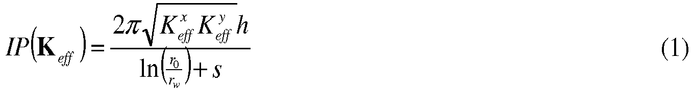
Avec : l'épaisseur perpendiculaire à l'écoulement h , rayon de puits rw , rayon de drainage r 0 et « skin factor » (qui est un facteur sans dimension qui traduit les pertes de charge engendrées par une restriction de débit à proximité des puits) s .With: the thickness perpendicular to the flow h , well radius r w , drainage radius r 0 and “skin factor” (which is a dimensionless factor which translates the pressure losses generated by a flow restriction near the well) s .
On remarque que r 0 est une fonction de la perméabilité : 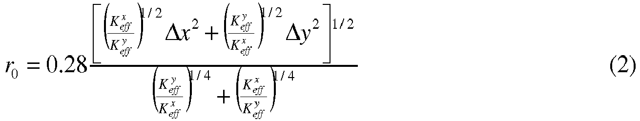
On calcule alors au moins un indice de productivité des puits IP(T,P) pour au moins une maille du modèle de réservoir, et de préférence pour chaque maille du modèle de réservoir perforée par le(s) puits en utilisant les perméabilités effectives mises à jour dans l'étape 2 : ![]()
![]()
![]()
![]()
![]()
![]()
En utilisant les formules de « Peaceman » (1, 2) et l'expression de Keff (T,P), on obtient l'indice de productivité en fonction de T et P ![]()
![]()

![]()
![]()
La présente invention est basée sur la prise en compte des effets thermiques sur les index de productivité des puits en tenant compte des effets thermiques sur la perméabilité par l'exhibition du multiplicateur de perméabilité dans la formule d'IP.The present invention is based on taking into account the thermal effects on the productivity indexes of the wells, taking into account the thermal effects on the permeability by the exhibition of the permeability multiplier in the formula of PI.
Lors de cette étape, on exploite la formation souterraine, c'est-à-dire on produit des hydrocarbures, en fonction des indices de productivité de puits déterminés à l'étape précédente.During this stage, the underground formation is exploited, that is to say hydrocarbons are produced, as a function of the well productivity indices determined in the preceding stage.
Selon un mode de réalisation de l'invention, à partir des indices de productivité des puits, les spécialistes peuvent déterminer plusieurs schémas d'exploitation correspondant à différentes configurations possibles d'exploitation du réservoir souterrain : emplacement des puits producteurs et/ou injecteurs, valeurs cibles pour les débits par puits et/ou pour le réservoir, le type d'outils utilisés, les fluides utilisés, injectés et/ou récupérés... Ces schémas de production peuvent être simulés au moyen d'un simulateur d'écoulement et du modèle de réservoir.According to one embodiment of the invention, on the basis of the productivity indices of the wells, the specialists can determine several operating diagrams corresponding to different possible configurations for operating the underground reservoir: location of the producing and / or injector wells, values targets for flow rates per well and / or for the reservoir, the type of tools used, the fluids used, injected and / or recovered ... These production schemes can be simulated using a flow simulator and the tank model.
A partir des indices de productivité des puits, et des éventuelles simulations d'écoulement, les spécialistes peuvent par comparaison choisir le schéma d'exploitation qui leur semble le plus pertinent. Par exemple :
- en comparant le maximum du volume d'huile récupéré, on peut déterminer le schéma de production susceptible de fournir le maximum de récupération ou d'être le plus rentable.
- en comparant l'écart type du volume d'huile récupéré, on peut déterminer le schéma de production le moins risqué.
- by comparing the maximum of the volume of oil recovered, one can determine the production scheme likely to provide the maximum recovery or to be the most profitable.
- by comparing the standard deviation of the volume of oil recovered, we can determine the least risky production scheme.
On exploite alors le réservoir selon le schéma d'exploitation défini par exemple en forant de nouveaux puits (producteur ou injecteur), en modifiant les outils utilisés, en modifiant les débits et/ou la nature de fluides injectés...The reservoir is then exploited according to the defined operating scheme, for example by drilling new wells (producer or injector), modifying the tools used, modifying the flow rates and / or the nature of the fluids injected ...
L'invention concerne par ailleurs un produit programme d'ordinateur téléchargeable depuis un réseau de communication et/ou enregistré sur un support lisible par ordinateur et/ou exécutable par un processeur. Ce programme comprend des instructions de code de programme pour la mise en œuvre du procédé tel que décrit ci-dessus, lorsque le programme est exécuté sur un ordinateur faisant partie du processus d'exploitation d'une formation souterraine.The invention also relates to a computer program product downloadable from a communication network and / or recorded on a computer-readable medium and / or executable by a processor. This program includes program code instructions for implementing the method as described above, when the program is executed on a computer forming part of the operating process of an underground formation.
Afin de montrer l'intérêt de cette méthode pour la simulation de production, on l'applique sur un cas simplifié de production de réservoir.In order to show the interest of this method for the production simulation, we apply it to a simplified case of reservoir production.
On utilise un modèle de simulation de SAGD (Steam-assisted gravity drainage) avec un puits producteur et un puits injecteur. D'abord, on préchauffe les puits fermés, ensuite on ouvre les puits pour équilibrer la pression. On injecte la vapeur dans le puits injecteur et on observe la production d'huile dans le puits producteur. Les variations de la température et de la pression sont très importantes dans ce processus ce qui permettra de mettre en évidence leurs rôles dans les effets géomécaniques.We use a SAGD (Steam-assisted gravity drainage) simulation model with a producer well and an injector well. First, preheat the closed wells, then open the wells to balance the pressure. Steam is injected into the injector well and oil production is observed in the producing well. The variations of temperature and pressure are very important in this process which will make it possible to highlight their roles in geomechanical effects.
On va démontrer l'influence de la prise en compte de la variation de perméabilité avec la température et la pression sur la production. Pour cela on compare des résultats des simulations :
- sans les effets géomécaniques, selon l'art antérieur (noté AA),
- seulement avec les effets de la pression sur les perméabilités et sur l'IP, selon l'art antérieur (noté Keff (P) et IP(P)) ; et
- avec les effets thermiques et de pression sur les perméabilités et sur l'IP selon l'invention (noté Keff (T,P) et IP(T,P)).
- without the geomechanical effects, according to the prior art (noted AA),
- only with the effects of pressure on the permeabilities and on the IP, according to the prior art (noted K eff ( P ) and IP ( P )); and
- with the thermal and pressure effects on the permeabilities and on the IP according to the invention (denoted K eff ( T, P ) and IP ( T, P )).
Les perméabilités initiales sont Kx = Ky = 2000 mD et Kz=1000 mD. Les multiplicateurs sont calculés en utilisant les modifications de la porosité en fonction de la température et la pression ![]()
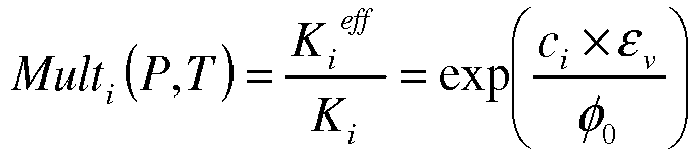
avec cx, cy et cz paramètres du matériau et εv une contrainte volumique calculée en considérant les variations de la porosité ainsi que de la température, εv = φ 0 cp(P-P 0) + 3αd (T-T 0) avec αd coefficient d'expansion thermique drainée.The initial permeabilities are K x = K y = 2000 mD and K z = 1000 mD. Multipliers are calculated using changes in porosity as a function of temperature and pressure ![]()
with c x , c y and c z parameters of the material and ε v a volumetric stress calculated by considering the variations of the porosity as well as the temperature, ε v = φ 0 c p (P - P 0 ) + 3α d ( T - T 0 ) with α d coefficient of drained thermal expansion.
Leurs valeurs sont données dans les tableaux 1 et 2, les multiplicateurs sont dépendants de la direction considérée horizontale ou verticale. Pour cet exemple illustratif et non limitatif, les facteurs Mult(T, P) sont obtenus par des lois physiques ou empiriques, telles que décrites dans le document Touhidi-Baghini (1998).
-
Touhidi-Baghini, A.: "Absolute Permeability of McMurray Formation Oil Sands at Low Confining Stress, Departement of Civil and Environmental Engineering, University of Alberta, Ph.D. Dissertation, 1998
-
Touhidi-Baghini, A .: "Absolute Permeability of McMurray Formation Oil Sands at Low Confining Stress, Department of Civil and Environmental Engineering, University of Alberta, Ph.D. Dissertation, 1998
La
En considérant une perméabilité et des IP variables en fonction de la température et de la pression, Keff (T,P) et IP(T,P), par la méthode selon l'invention définie ci-dessus (courbe (-■-)), on obtient l'estimation de la production significativement différente par rapport au cas sans les effets thermiques Keff (P) et IP(P) (courbe (--□--)) selon l'art antérieur. Dans un premier temps, l'effet de la hausse de la température augmente les perméabilités et les IP. Ce qui amène à produire plus rapidement que dans la cas sans effet de la température. L'huile étant produite plus rapidement, on assiste à une baisse de production après 700 jours.By considering a permeability and variable PIs as a function of temperature and pressure, K eff ( T, P ) and PI ( T, P ), by the method according to the invention defined above (curve (- ■ - )), we obtain the estimate of production significantly different from the case without the thermal effects K eff ( P ) and IP ( P ) (curve (- □ -)) according to the prior art. Initially, the effect of the rise in temperature increases the permeabilities and the PIs. Which leads to produce faster than in the case without temperature effect. As the oil is produced more quickly, there is a drop in production after 700 days.
La
Claims (5)
- Production method for hydrocarbons contained in an underground formation passed through by at least one well, characterized in that the following steps are carried out:- a computer is used to construct a numerical model of said underground formation comprising a meshing, and by taking into account at least petrophysical data applied to the meshes, and the characteristics of at least one well passing through said underground formation,- a function of pressure and temperature dependencies of the permeabilities taken into account in said model is determined, said function of pressure and temperature dependencies of the permeabilities taken into account in said model comprising permeability multipliers Multi(T,P), in order to have an effective permeability
 - a model of productivity index as a function of the permeability of said meshes is determined, according to:
 - for at least one mesh of said model, a pressure and temperature dependent productivity index is determined, by taking into account said functions of pressure and temperature dependencies of the permeabilities, and said productivity index model, and- said underground formation is exploited as a function of said productivity index.
 - Hydrocarbon production method according to Claim 1, in which said multipliers are determined by using the modifications of the porosity as a function of temperature and pressure.
- Hydrocarbon production method according to either of Claims 1 and 2, applied to a thermal drainage method.
- Hydrocarbon production method according to one of the preceding claims, in which the productivity index is determined for the meshes of said numerical model affected by said well.
- Computer program product that can be downloaded from a communication network and/or stored on a computer-readable medium and/or that can be executed by a processor, comprising program code instructions for implementing the method according to one of the preceding claims, when said program is run on a computer which forms part of the process of exploitation of an underground formation.
Applications Claiming Priority (1)
| Application Number | Priority Date | Filing Date | Title |
|---|---|---|---|
| FR1650309A FR3046810B1 (en) | 2016-01-15 | 2016-01-15 | PROCESS FOR PRODUCING HYDROCARBONS COMPRISING A THERMAL EFFECT WELL PRODUCTIVITY INDEX |
Publications (2)
| Publication Number | Publication Date |
|---|---|
| EP3192964A1 EP3192964A1 (en) | 2017-07-19 |
| EP3192964B1 true EP3192964B1 (en) | 2020-05-13 |
Family
ID=55759796
Family Applications (1)
| Application Number | Title | Priority Date | Filing Date |
|---|---|---|---|
| EP16306686.3A Active EP3192964B1 (en) | 2016-01-15 | 2016-12-15 | Method for producing hydrocarbons comprising a productivity index of wells under thermal effect |
Country Status (4)
| Country | Link |
|---|---|
| US (1) | US10538995B2 (en) |
| EP (1) | EP3192964B1 (en) |
| CA (1) | CA2954354C (en) |
| FR (1) | FR3046810B1 (en) |
Families Citing this family (3)
| Publication number | Priority date | Publication date | Assignee | Title |
|---|---|---|---|---|
| CN109408838B (en) * | 2017-08-16 | 2021-12-07 | 中国石油化工股份有限公司 | Method and system for rapidly analyzing residual oil of fracture-cavity oil reservoir |
| CN110632677B (en) * | 2019-09-26 | 2020-09-15 | 中石化石油工程技术服务有限公司 | A classification method for carbonate geothermal reservoirs |
| CN120150215B (en) * | 2025-05-16 | 2025-09-02 | 国网江西省电力有限公司经济技术研究院 | Energy storage planning method and system considering the evolution path of renewable energy proportion |
Family Cites Families (4)
| Publication number | Priority date | Publication date | Assignee | Title |
|---|---|---|---|---|
| US6549879B1 (en) * | 1999-09-21 | 2003-04-15 | Mobil Oil Corporation | Determining optimal well locations from a 3D reservoir model |
| US8280709B2 (en) * | 2008-10-03 | 2012-10-02 | Schlumberger Technology Corporation | Fully coupled simulation for fluid flow and geomechanical properties in oilfield simulation operations |
| EP2599023B1 (en) * | 2010-07-29 | 2019-10-23 | Exxonmobil Upstream Research Company | Methods and systems for machine-learning based simulation of flow |
| CA2820742A1 (en) * | 2013-07-04 | 2013-09-20 | IOR Canada Ltd. | Improved hydrocarbon recovery process exploiting multiple induced fractures |
-
2016
- 2016-01-15 FR FR1650309A patent/FR3046810B1/en active Active
- 2016-12-15 EP EP16306686.3A patent/EP3192964B1/en active Active
-
2017
- 2017-01-10 CA CA2954354A patent/CA2954354C/en active Active
- 2017-01-13 US US15/406,351 patent/US10538995B2/en active Active
Non-Patent Citations (1)
| Title |
|---|
| None * |
Also Published As
| Publication number | Publication date |
|---|---|
| CA2954354C (en) | 2023-07-11 |
| US10538995B2 (en) | 2020-01-21 |
| CA2954354A1 (en) | 2017-07-15 |
| FR3046810A1 (en) | 2017-07-21 |
| EP3192964A1 (en) | 2017-07-19 |
| FR3046810B1 (en) | 2018-01-26 |
| US20170204706A1 (en) | 2017-07-20 |
Similar Documents
| Publication | Publication Date | Title |
|---|---|---|
| EP2253797B1 (en) | Method of exploitation of a porous medium by modelling of fluid flows | |
| EP2072752B1 (en) | Method for optimising the exploitation of a fluid reservoir by taking into consideration a geological and transitional exchange term between matrix blocks and fractures | |
| EP3144468B1 (en) | Method for characterising the network of fractures of a fractured deposit and method for exploiting same | |
| Alpak et al. | The impact of fine-scale turbidite channel architecture on deep-water reservoir performance | |
| FR2823877A1 (en) | METHOD FOR CONSTRAINING BY DYNAMIC PRODUCTION DATA A FINE MODEL REPRESENTATIVE OF THE DISTRIBUTION IN THE DEPOSIT OF A CHARACTERISTIC PHYSICAL SIZE OF THE BASEMENT STRUCTURE | |
| CA2746900C (en) | Method for developing an oil field using a reservoir model that is gradually distorted through co-simulations | |
| EP3719251A1 (en) | Method for exploiting a fractured oil reservoir having a heterogeneous pore size | |
| CA2821099C (en) | Production process for a geological reservoir based on a stock reservoir by calculating an analytical conditional distribution law of uncertain parameters of the model | |
| EP2963235B1 (en) | Method for exploiting an oil deposit based on a technique for positioning wells to be drilled | |
| CA2812095C (en) | Selection process for positioning wells to be drilled for an oil deposit operation | |
| EP2813668B1 (en) | Method for optimising the exploitation of a fluid reservoir by taking into consideration a geological and transitional exchange term between matrix blocks and cracks | |
| EP2770162B1 (en) | Method for exploiting a geological reservoir by means of a wedge model of the reservoir that is consistent with the flow properties | |
| FR3045868A1 (en) | METHOD FOR CHARACTERIZING AND EXPLOITING UNDERGROUND FORMATION COMPRISING A FRACTURE NETWORK | |
| EP3192964B1 (en) | Method for producing hydrocarbons comprising a productivity index of wells under thermal effect | |
| FR3059443A1 (en) | METHOD OF OPERATING A HYDROCARBON STORAGE BY SETTING PRODUCTION HISTORY FUNCTION OF DIAGENESIS | |
| EP3199749A1 (en) | Method for exploiting a fluid reservoir having fractures passing through same by means of a flow simulation based on an exchange flow and a corrective factor | |
| CA2732474C (en) | Method of history matching of a geological model equipped with a network of sub-seismic faults | |
| FR3048300A1 (en) | 3D GEOCELLULAR HYBRID REPRESENTATION OF SELECTED NATURAL FRACTURE NETWORK SUBASSEMBLIES | |
| US11867862B2 (en) | Method for validating rock formations compaction parameters using geomechanical modeling | |
| Parvizi et al. | Hydraulic fracturing performance evaluation in tight sand gas reservoirs with high perm streaks and natural fractures | |
| Al-Khazraji et al. | Development of heterogeneous immature Brownfield with Waterdrive using dynamic opportunity index: a case study from Iraqi oilfields | |
| Joslin et al. | Viability of eor processes in the bakken under geological and economic uncertainty | |
| EP3626929A1 (en) | Method for operating a hydrocarbon reservoir by injecting a polymer | |
| Mata et al. | Modeling the Influence of Pressure Depletion in Fracture Propagation and Quantifying the Impact of Asymmetric Fracture Wings in Ultimate Recovery | |
| Ghadami et al. | Robust chemical EOR modelling from coreflood to full field scale in a Brown Field, Offshore |
Legal Events
| Date | Code | Title | Description |
|---|---|---|---|
| PUAI | Public reference made under article 153(3) epc to a published international application that has entered the european phase |
Free format text: ORIGINAL CODE: 0009012 |
|
| STAA | Information on the status of an ep patent application or granted ep patent |
Free format text: STATUS: THE APPLICATION HAS BEEN PUBLISHED |
|
| AK | Designated contracting states |
Kind code of ref document: A1 Designated state(s): AL AT BE BG CH CY CZ DE DK EE ES FI FR GB GR HR HU IE IS IT LI LT LU LV MC MK MT NL NO PL PT RO RS SE SI SK SM TR |
|
| AX | Request for extension of the european patent |
Extension state: BA ME |
|
| RAP1 | Party data changed (applicant data changed or rights of an application transferred) |
Owner name: IFP ENERGIES NOUVELLES |
|
| STAA | Information on the status of an ep patent application or granted ep patent |
Free format text: STATUS: REQUEST FOR EXAMINATION WAS MADE |
|
| 17P | Request for examination filed |
Effective date: 20180119 |
|
| RBV | Designated contracting states (corrected) |
Designated state(s): AL AT BE BG CH CY CZ DE DK EE ES FI FR GB GR HR HU IE IS IT LI LT LU LV MC MK MT NL NO PL PT RO RS SE SI SK SM TR |
|
| STAA | Information on the status of an ep patent application or granted ep patent |
Free format text: STATUS: EXAMINATION IS IN PROGRESS |
|
| 17Q | First examination report despatched |
Effective date: 20181126 |
|
| GRAP | Despatch of communication of intention to grant a patent |
Free format text: ORIGINAL CODE: EPIDOSNIGR1 |
|
| STAA | Information on the status of an ep patent application or granted ep patent |
Free format text: STATUS: GRANT OF PATENT IS INTENDED |
|
| INTG | Intention to grant announced |
Effective date: 20191219 |
|
| GRAS | Grant fee paid |
Free format text: ORIGINAL CODE: EPIDOSNIGR3 |
|
| GRAA | (expected) grant |
Free format text: ORIGINAL CODE: 0009210 |
|
| STAA | Information on the status of an ep patent application or granted ep patent |
Free format text: STATUS: THE PATENT HAS BEEN GRANTED |
|
| AK | Designated contracting states |
Kind code of ref document: B1 Designated state(s): AL AT BE BG CH CY CZ DE DK EE ES FI FR GB GR HR HU IE IS IT LI LT LU LV MC MK MT NL NO PL PT RO RS SE SI SK SM TR |
|
| REG | Reference to a national code |
Ref country code: GB Ref legal event code: FG4D Free format text: NOT ENGLISH |
|
| REG | Reference to a national code |
Ref country code: CH Ref legal event code: EP |
|
| REG | Reference to a national code |
Ref country code: DE Ref legal event code: R096 Ref document number: 602016036315 Country of ref document: DE |
|
| REG | Reference to a national code |
Ref country code: AT Ref legal event code: REF Ref document number: 1270519 Country of ref document: AT Kind code of ref document: T Effective date: 20200615 |
|
| REG | Reference to a national code |
Ref country code: NO Ref legal event code: T2 Effective date: 20200513 |
|
| REG | Reference to a national code |
Ref country code: LT Ref legal event code: MG4D |
|
| REG | Reference to a national code |
Ref country code: NL Ref legal event code: MP Effective date: 20200513 |
|
| PG25 | Lapsed in a contracting state [announced via postgrant information from national office to epo] |
Ref country code: IS Free format text: LAPSE BECAUSE OF FAILURE TO SUBMIT A TRANSLATION OF THE DESCRIPTION OR TO PAY THE FEE WITHIN THE PRESCRIBED TIME-LIMIT Effective date: 20200913 Ref country code: GR Free format text: LAPSE BECAUSE OF FAILURE TO SUBMIT A TRANSLATION OF THE DESCRIPTION OR TO PAY THE FEE WITHIN THE PRESCRIBED TIME-LIMIT Effective date: 20200814 Ref country code: PT Free format text: LAPSE BECAUSE OF FAILURE TO SUBMIT A TRANSLATION OF THE DESCRIPTION OR TO PAY THE FEE WITHIN THE PRESCRIBED TIME-LIMIT Effective date: 20200914 Ref country code: FI Free format text: LAPSE BECAUSE OF FAILURE TO SUBMIT A TRANSLATION OF THE DESCRIPTION OR TO PAY THE FEE WITHIN THE PRESCRIBED TIME-LIMIT Effective date: 20200513 Ref country code: LT Free format text: LAPSE BECAUSE OF FAILURE TO SUBMIT A TRANSLATION OF THE DESCRIPTION OR TO PAY THE FEE WITHIN THE PRESCRIBED TIME-LIMIT Effective date: 20200513 Ref country code: SE Free format text: LAPSE BECAUSE OF FAILURE TO SUBMIT A TRANSLATION OF THE DESCRIPTION OR TO PAY THE FEE WITHIN THE PRESCRIBED TIME-LIMIT Effective date: 20200513 |
|
| PG25 | Lapsed in a contracting state [announced via postgrant information from national office to epo] |
Ref country code: LV Free format text: LAPSE BECAUSE OF FAILURE TO SUBMIT A TRANSLATION OF THE DESCRIPTION OR TO PAY THE FEE WITHIN THE PRESCRIBED TIME-LIMIT Effective date: 20200513 Ref country code: HR Free format text: LAPSE BECAUSE OF FAILURE TO SUBMIT A TRANSLATION OF THE DESCRIPTION OR TO PAY THE FEE WITHIN THE PRESCRIBED TIME-LIMIT Effective date: 20200513 Ref country code: RS Free format text: LAPSE BECAUSE OF FAILURE TO SUBMIT A TRANSLATION OF THE DESCRIPTION OR TO PAY THE FEE WITHIN THE PRESCRIBED TIME-LIMIT Effective date: 20200513 Ref country code: BG Free format text: LAPSE BECAUSE OF FAILURE TO SUBMIT A TRANSLATION OF THE DESCRIPTION OR TO PAY THE FEE WITHIN THE PRESCRIBED TIME-LIMIT Effective date: 20200813 |
|
| REG | Reference to a national code |
Ref country code: AT Ref legal event code: MK05 Ref document number: 1270519 Country of ref document: AT Kind code of ref document: T Effective date: 20200513 |
|
| PG25 | Lapsed in a contracting state [announced via postgrant information from national office to epo] |
Ref country code: AL Free format text: LAPSE BECAUSE OF FAILURE TO SUBMIT A TRANSLATION OF THE DESCRIPTION OR TO PAY THE FEE WITHIN THE PRESCRIBED TIME-LIMIT Effective date: 20200513 Ref country code: NL Free format text: LAPSE BECAUSE OF FAILURE TO SUBMIT A TRANSLATION OF THE DESCRIPTION OR TO PAY THE FEE WITHIN THE PRESCRIBED TIME-LIMIT Effective date: 20200513 |
|
| PG25 | Lapsed in a contracting state [announced via postgrant information from national office to epo] |
Ref country code: DK Free format text: LAPSE BECAUSE OF FAILURE TO SUBMIT A TRANSLATION OF THE DESCRIPTION OR TO PAY THE FEE WITHIN THE PRESCRIBED TIME-LIMIT Effective date: 20200513 Ref country code: ES Free format text: LAPSE BECAUSE OF FAILURE TO SUBMIT A TRANSLATION OF THE DESCRIPTION OR TO PAY THE FEE WITHIN THE PRESCRIBED TIME-LIMIT Effective date: 20200513 Ref country code: AT Free format text: LAPSE BECAUSE OF FAILURE TO SUBMIT A TRANSLATION OF THE DESCRIPTION OR TO PAY THE FEE WITHIN THE PRESCRIBED TIME-LIMIT Effective date: 20200513 Ref country code: RO Free format text: LAPSE BECAUSE OF FAILURE TO SUBMIT A TRANSLATION OF THE DESCRIPTION OR TO PAY THE FEE WITHIN THE PRESCRIBED TIME-LIMIT Effective date: 20200513 Ref country code: CZ Free format text: LAPSE BECAUSE OF FAILURE TO SUBMIT A TRANSLATION OF THE DESCRIPTION OR TO PAY THE FEE WITHIN THE PRESCRIBED TIME-LIMIT Effective date: 20200513 Ref country code: EE Free format text: LAPSE BECAUSE OF FAILURE TO SUBMIT A TRANSLATION OF THE DESCRIPTION OR TO PAY THE FEE WITHIN THE PRESCRIBED TIME-LIMIT Effective date: 20200513 Ref country code: SM Free format text: LAPSE BECAUSE OF FAILURE TO SUBMIT A TRANSLATION OF THE DESCRIPTION OR TO PAY THE FEE WITHIN THE PRESCRIBED TIME-LIMIT Effective date: 20200513 Ref country code: IT Free format text: LAPSE BECAUSE OF FAILURE TO SUBMIT A TRANSLATION OF THE DESCRIPTION OR TO PAY THE FEE WITHIN THE PRESCRIBED TIME-LIMIT Effective date: 20200513 |
|
| REG | Reference to a national code |
Ref country code: DE Ref legal event code: R097 Ref document number: 602016036315 Country of ref document: DE |
|
| PG25 | Lapsed in a contracting state [announced via postgrant information from national office to epo] |
Ref country code: PL Free format text: LAPSE BECAUSE OF FAILURE TO SUBMIT A TRANSLATION OF THE DESCRIPTION OR TO PAY THE FEE WITHIN THE PRESCRIBED TIME-LIMIT Effective date: 20200513 Ref country code: SK Free format text: LAPSE BECAUSE OF FAILURE TO SUBMIT A TRANSLATION OF THE DESCRIPTION OR TO PAY THE FEE WITHIN THE PRESCRIBED TIME-LIMIT Effective date: 20200513 |
|
| PLBE | No opposition filed within time limit |
Free format text: ORIGINAL CODE: 0009261 |
|
| STAA | Information on the status of an ep patent application or granted ep patent |
Free format text: STATUS: NO OPPOSITION FILED WITHIN TIME LIMIT |
|
| 26N | No opposition filed |
Effective date: 20210216 |
|
| PG25 | Lapsed in a contracting state [announced via postgrant information from national office to epo] |
Ref country code: SI Free format text: LAPSE BECAUSE OF FAILURE TO SUBMIT A TRANSLATION OF THE DESCRIPTION OR TO PAY THE FEE WITHIN THE PRESCRIBED TIME-LIMIT Effective date: 20200513 |
|
| REG | Reference to a national code |
Ref country code: DE Ref legal event code: R119 Ref document number: 602016036315 Country of ref document: DE |
|
| REG | Reference to a national code |
Ref country code: CH Ref legal event code: PL |
|
| PG25 | Lapsed in a contracting state [announced via postgrant information from national office to epo] |
Ref country code: MC Free format text: LAPSE BECAUSE OF FAILURE TO SUBMIT A TRANSLATION OF THE DESCRIPTION OR TO PAY THE FEE WITHIN THE PRESCRIBED TIME-LIMIT Effective date: 20200513 |
|
| REG | Reference to a national code |
Ref country code: BE Ref legal event code: MM Effective date: 20201231 |
|
| PG25 | Lapsed in a contracting state [announced via postgrant information from national office to epo] |
Ref country code: IE Free format text: LAPSE BECAUSE OF NON-PAYMENT OF DUE FEES Effective date: 20201215 Ref country code: LU Free format text: LAPSE BECAUSE OF NON-PAYMENT OF DUE FEES Effective date: 20201215 |
|
| PG25 | Lapsed in a contracting state [announced via postgrant information from national office to epo] |
Ref country code: DE Free format text: LAPSE BECAUSE OF NON-PAYMENT OF DUE FEES Effective date: 20210701 Ref country code: CH Free format text: LAPSE BECAUSE OF NON-PAYMENT OF DUE FEES Effective date: 20201231 Ref country code: LI Free format text: LAPSE BECAUSE OF NON-PAYMENT OF DUE FEES Effective date: 20201231 |
|
| PG25 | Lapsed in a contracting state [announced via postgrant information from national office to epo] |
Ref country code: TR Free format text: LAPSE BECAUSE OF FAILURE TO SUBMIT A TRANSLATION OF THE DESCRIPTION OR TO PAY THE FEE WITHIN THE PRESCRIBED TIME-LIMIT Effective date: 20200513 Ref country code: MT Free format text: LAPSE BECAUSE OF FAILURE TO SUBMIT A TRANSLATION OF THE DESCRIPTION OR TO PAY THE FEE WITHIN THE PRESCRIBED TIME-LIMIT Effective date: 20200513 Ref country code: CY Free format text: LAPSE BECAUSE OF FAILURE TO SUBMIT A TRANSLATION OF THE DESCRIPTION OR TO PAY THE FEE WITHIN THE PRESCRIBED TIME-LIMIT Effective date: 20200513 |
|
| PG25 | Lapsed in a contracting state [announced via postgrant information from national office to epo] |
Ref country code: MK Free format text: LAPSE BECAUSE OF FAILURE TO SUBMIT A TRANSLATION OF THE DESCRIPTION OR TO PAY THE FEE WITHIN THE PRESCRIBED TIME-LIMIT Effective date: 20200513 |
|
| PG25 | Lapsed in a contracting state [announced via postgrant information from national office to epo] |
Ref country code: BE Free format text: LAPSE BECAUSE OF NON-PAYMENT OF DUE FEES Effective date: 20201231 |
|
| PGFP | Annual fee paid to national office [announced via postgrant information from national office to epo] |
Ref country code: NO Payment date: 20241219 Year of fee payment: 9 |
|
| PGFP | Annual fee paid to national office [announced via postgrant information from national office to epo] |
Ref country code: GB Payment date: 20241217 Year of fee payment: 9 |
|
| PGFP | Annual fee paid to national office [announced via postgrant information from national office to epo] |
Ref country code: FR Payment date: 20241227 Year of fee payment: 9 |