EP3154464B1 - Apparatus for rapid and selective tissue ablation with cooling - Google Patents
Apparatus for rapid and selective tissue ablation with cooling Download PDFInfo
- Publication number
- EP3154464B1 EP3154464B1 EP15806855.1A EP15806855A EP3154464B1 EP 3154464 B1 EP3154464 B1 EP 3154464B1 EP 15806855 A EP15806855 A EP 15806855A EP 3154464 B1 EP3154464 B1 EP 3154464B1
- Authority
- EP
- European Patent Office
- Prior art keywords
- electrode
- temperature
- target tissue
- arm
- cooling
- Prior art date
- Legal status (The legal status is an assumption and is not a legal conclusion. Google has not performed a legal analysis and makes no representation as to the accuracy of the status listed.)
- Active
Links
Images


Classifications
-
- A—HUMAN NECESSITIES
- A61—MEDICAL OR VETERINARY SCIENCE; HYGIENE
- A61B—DIAGNOSIS; SURGERY; IDENTIFICATION
- A61B18/00—Surgical instruments, devices or methods for transferring non-mechanical forms of energy to or from the body
- A61B18/04—Surgical instruments, devices or methods for transferring non-mechanical forms of energy to or from the body by heating
- A61B18/12—Surgical instruments, devices or methods for transferring non-mechanical forms of energy to or from the body by heating by passing a current through the tissue to be heated, e.g. high-frequency current
- A61B18/14—Probes or electrodes therefor
-
- A—HUMAN NECESSITIES
- A61—MEDICAL OR VETERINARY SCIENCE; HYGIENE
- A61B—DIAGNOSIS; SURGERY; IDENTIFICATION
- A61B17/00—Surgical instruments, devices or methods
- A61B17/08—Wound clamps or clips, i.e. not or only partly penetrating the tissue ; Devices for bringing together the edges of a wound
-
- A—HUMAN NECESSITIES
- A61—MEDICAL OR VETERINARY SCIENCE; HYGIENE
- A61B—DIAGNOSIS; SURGERY; IDENTIFICATION
- A61B18/00—Surgical instruments, devices or methods for transferring non-mechanical forms of energy to or from the body
- A61B18/04—Surgical instruments, devices or methods for transferring non-mechanical forms of energy to or from the body by heating
- A61B18/12—Surgical instruments, devices or methods for transferring non-mechanical forms of energy to or from the body by heating by passing a current through the tissue to be heated, e.g. high-frequency current
- A61B18/1206—Generators therefor
-
- A—HUMAN NECESSITIES
- A61—MEDICAL OR VETERINARY SCIENCE; HYGIENE
- A61B—DIAGNOSIS; SURGERY; IDENTIFICATION
- A61B18/00—Surgical instruments, devices or methods for transferring non-mechanical forms of energy to or from the body
- A61B18/04—Surgical instruments, devices or methods for transferring non-mechanical forms of energy to or from the body by heating
- A61B18/12—Surgical instruments, devices or methods for transferring non-mechanical forms of energy to or from the body by heating by passing a current through the tissue to be heated, e.g. high-frequency current
- A61B18/14—Probes or electrodes therefor
- A61B18/1442—Probes having pivoting end effectors, e.g. forceps
-
- A—HUMAN NECESSITIES
- A61—MEDICAL OR VETERINARY SCIENCE; HYGIENE
- A61B—DIAGNOSIS; SURGERY; IDENTIFICATION
- A61B18/00—Surgical instruments, devices or methods for transferring non-mechanical forms of energy to or from the body
- A61B2018/00005—Cooling or heating of the probe or tissue immediately surrounding the probe
-
- A—HUMAN NECESSITIES
- A61—MEDICAL OR VETERINARY SCIENCE; HYGIENE
- A61B—DIAGNOSIS; SURGERY; IDENTIFICATION
- A61B18/00—Surgical instruments, devices or methods for transferring non-mechanical forms of energy to or from the body
- A61B2018/00315—Surgical instruments, devices or methods for transferring non-mechanical forms of energy to or from the body for treatment of particular body parts
- A61B2018/00452—Skin
- A61B2018/00458—Deeper parts of the skin, e.g. treatment of vascular disorders or port wine stains
- A61B2018/00464—Subcutaneous fat, e.g. liposuction, lipolysis
-
- A—HUMAN NECESSITIES
- A61—MEDICAL OR VETERINARY SCIENCE; HYGIENE
- A61B—DIAGNOSIS; SURGERY; IDENTIFICATION
- A61B18/00—Surgical instruments, devices or methods for transferring non-mechanical forms of energy to or from the body
- A61B2018/00571—Surgical instruments, devices or methods for transferring non-mechanical forms of energy to or from the body for achieving a particular surgical effect
- A61B2018/00613—Irreversible electroporation
-
- A—HUMAN NECESSITIES
- A61—MEDICAL OR VETERINARY SCIENCE; HYGIENE
- A61B—DIAGNOSIS; SURGERY; IDENTIFICATION
- A61B18/00—Surgical instruments, devices or methods for transferring non-mechanical forms of energy to or from the body
- A61B2018/00636—Sensing and controlling the application of energy
- A61B2018/00642—Sensing and controlling the application of energy with feedback, i.e. closed loop control
-
- A—HUMAN NECESSITIES
- A61—MEDICAL OR VETERINARY SCIENCE; HYGIENE
- A61B—DIAGNOSIS; SURGERY; IDENTIFICATION
- A61B18/00—Surgical instruments, devices or methods for transferring non-mechanical forms of energy to or from the body
- A61B2018/00636—Sensing and controlling the application of energy
- A61B2018/00696—Controlled or regulated parameters
- A61B2018/00702—Power or energy
-
- A—HUMAN NECESSITIES
- A61—MEDICAL OR VETERINARY SCIENCE; HYGIENE
- A61B—DIAGNOSIS; SURGERY; IDENTIFICATION
- A61B18/00—Surgical instruments, devices or methods for transferring non-mechanical forms of energy to or from the body
- A61B2018/00636—Sensing and controlling the application of energy
- A61B2018/00773—Sensed parameters
- A61B2018/00779—Power or energy
-
- A—HUMAN NECESSITIES
- A61—MEDICAL OR VETERINARY SCIENCE; HYGIENE
- A61B—DIAGNOSIS; SURGERY; IDENTIFICATION
- A61B18/00—Surgical instruments, devices or methods for transferring non-mechanical forms of energy to or from the body
- A61B2018/00636—Sensing and controlling the application of energy
- A61B2018/00773—Sensed parameters
- A61B2018/00791—Temperature
-
- A—HUMAN NECESSITIES
- A61—MEDICAL OR VETERINARY SCIENCE; HYGIENE
- A61B—DIAGNOSIS; SURGERY; IDENTIFICATION
- A61B90/00—Instruments, implements or accessories specially adapted for surgery or diagnosis and not covered by any of the groups A61B1/00 - A61B50/00, e.g. for luxation treatment or for protecting wound edges
- A61B90/06—Measuring instruments not otherwise provided for
- A61B2090/061—Measuring instruments not otherwise provided for for measuring dimensions, e.g. length
Definitions
- the embodiments described herein relate generally to medical devices for therapeutic electrical energy delivery, and more particularly to systems for delivering electrical energy in the context of ablating tissue rapidly and selectively by the application of suitably timed pulsed voltages that generate irreversible electroporation of cell membranes, in conjunction with the application of suitable regional cooling to enhance electroporation selectivity and efficacy.
- the electroporation is irreversible and the pores remain open, permitting exchange of material across the membrane and leading to apoptosis or cell death. Subsequently the tissue heals in a natural process.
- Some known processes of adipose tissue reduction by freezing also known as cryogenically induced lipolysis, can involve a significant length of therapy time.
- the action of irreversible electroporation can be much more rapid.
- Some known tissue ablation methods employing irreversible electroporation involve destroying a significant mass of tissue, and one concern the temperature increase in the tissue resulting from this ablation process.
- the embodiments described herein address the need for tools for rapid and selective application of irreversible electroporation therapy as well as pulse generation and control methods.
- the process of irreversible electroporation can be induced even without the flow of current when a polarizing high voltage is applied to generate a suitably large electric field in a region of interest.
- the embodiments described herein can result in well-controlled and specific delivery of electroporation in an efficacious manner.
- an apparatus includes a voltage pulse generator configured to produce a pulsed voltage waveform, and an electrode controller.
- the electrode controller is configured to be operably coupled to the voltage pulse generator and a medical clamp.
- the medical clamp includes a plurality of electrodes.
- the electrode controller is implemented in at least one of a memory or a processor, and includes a feedback module, a cooling module and a pulse delivery module.
- the feedback module is configured to determine a temperature of a target tissue to which the medical clamp is coupled.
- the cooling module is configured to produce a signal to a cooling unit of the medical clamp to maintain a portion of the target tissue at a target temperature.
- the pulse delivery module is configured to deliver an output signal associated with the pulsed voltage waveform to the plurality of electrodes.
- a method includes receiving, at a feedback module of an electrode controller, a signal associated with a temperature of a target tissue to which a medical clamp is coupled.
- the medical clamp includes a plurality of electrodes.
- a signal based at least in part on the temperature of the target tissue is produced.
- the signal is then delivered to a cooling unit of the medical clamp to maintain a portion of the target tissue at a target temperature.
- the method includes delivering an output signal associated with the pulsed voltage waveform to the plurality of electrodes when the target tissue is at the target temperature.
- an irreversible electroporation system includes a DC voltage/signal generator and a controller capable of being configured to apply voltages to a selected multiplicity of electrodes. Further, the controller is capable of applying control inputs whereby selected pairs of anode-cathode subsets of electrodes can be sequentially updated based on a pre-determined sequence. In some embodiments, the controller can further receive at least one temperature input, and based on a temperature input the controller can modify or update a control parameter that can help to maintain a temperature value near a region of interest.
- the generator can output waveforms that can be selected to generate a sequence of voltage pulses in either monophasic or biphasic forms and with either constant or progressively changing amplitudes.
- the system can include a means for sensing electrode separation, and the electrode voltage applied can be determined based on a sensed separation or distance measure. This determination can be fully or partially automatic, or manual.
- a system uses temperature to selectively ablate tissue as the threshold of irreversible electroporation is temperature-dependent, utilizing means such as the suitable use of cooling fluid or solid state cooling methods to locally raise the irreversible electroporation threshold electric field value and thereby selecting the predominant tissue type or region it is desired to ablate.
- adipose tissue reduction by freezing also known as cryogenically induced lipolysis, which uses lower temperatures to directly freeze adipose tissue
- the lowered temperatures assist in the selective action of irreversible electroporation, a much more rapid process than freezing.
- an irreversible electroporation system includes a DC voltage/signal generator and a controller that is configured to apply voltages to a selected multiplicity or a subset of electrodes.
- a temperature measurement device such as a thermistor measures temperature at or near a portion of an electrode device.
- the controller is capable of applying control inputs whereby the temperature at or near a portion of the device is maintained within a narrow range of desired values.
- the temperature at or near an electrode or electrode head surface contacting a patient anatomy is maintained at or near a value that is lower than body temperature.
- the application of DC voltage pulses is made only when the temperature is within a narrow range of values around a desired value.
- At least one control input for temperature control takes the form of rate of flow of a cooling fluid, while in another embodiment, the control input is a voltage that drives a thermoelectric heat pump. Further, in some embodiments, the electrode clamp device disclosed here incorporates a sensor to measure a separation distance, based on which the electroporation voltage value is selected.
- a DC voltage for electroporation can be applied to subsets of electrodes identified as anode and cathode respectively on opposite sides of an anatomical region it is desired to ablate.
- the DC voltage is applied in brief pulses sufficient to cause irreversible electroporation and can preferably be in the range of 0.5 kV to 60 kV and more preferably in the range 1 kV to 10 kV, so that an appropriate threshold electric field value of at least around 800 Volts/cm is effectively achieved in the tissue (for example, adipose tissue) to be ablated.
- the DC voltage generator setting for irreversible electroporation is automatically identified by the electroporation system based on a sensed distance measuring the spatial separation between electrodes of opposing polarities.
- the DC voltage value is selected directly by a user from a suitable dial, slider, touch screen, or any other user interface.
- transient currents may be induced in the tissue upon voltage application or removal, there are no other (steady state) currents as the electrodes are insulated from the subject anatomy.
- a region or volume of tissue where the electric field is sufficiently large for irreversible electroporation to occur is ablated during the DC voltage pulse application.
- the application of surface cooling raises the electroporation threshold of tissue near the surface and prevents the occurrence of irreversible electroporation in this surface layer.
- the terms "about” and “approximately” generally mean plus or minus 10% of the value stated. For example, about 0.5 would include 0.45 and 0.55, about 10 would include 9 to 11, about 1000 would include 900 to 1100.
- FIG. 1A A schematic diagram of the electroporation system according to an embodiment is shown in FIG. 1A .
- the system includes a DC voltage/signal generator 23 is driven by a controller unit 21 that interfaces with a computer device 24 by means of a two-way communication link 29.
- the controller can perform channel selection and routing functions for applying DC voltages to appropriate electrodes that have been selected by a user or by the computer 24, and apply the voltages via a multiplicity of leads (shown collectively as 26) to an electrode device 22.
- the electrode device 22, and any of the electrode devices described herein can be similar to the ablation catheters described in PCT Publication No. WO2014/025394, entitled “Catheters, Catheter Systems, and Methods for Puncturing Through a Tissue Structure," filed on March 14, 2013 ("the '394 PCT Application).
- the leads 26 from the controller 21 can also carry control signals to adjust temperature at or near the electrode device.
- the control signals from the controller 21 can be routed to a different unit (not shown) such as a cooling pump for example, to control cooling fluid flow rate).
- the electrode device 22 can also send information and/or signals to the controller 21, such as temperature data from sensors mounted on or near the electrode device. Such feedback signals are indicated by the data stream 25, which can be sent via separate leads. While the DC voltage generator 23 sends a DC voltage to the controller 21 through leads 27, the voltage generator is driven by control and timing inputs 28 from the controller unit 21.
- the electrode controller can include one or more modules and can automatically control the temperature of a target tissue, adjust a characteristic of the voltage waveform based on the spacing between adjacent electrodes, or the like.
- FIG. 1B shows an electroporation system according to an embodiment that includes an electrode controller 900 and a signal generator 925.
- the electrode controller 900 is coupled to a computer 920 or other input / output device, and is configured to be operably coupled to a medical device 930.
- the medical device 930 can be one or more of the medical clamps of the types shown and described herein. Further the medical device 930 can be coupled to, disposed about and/or in contact with a target tissue T. In this manner, as described herein, the electroporation system, including the electrode controller 900 and the signal generator 925, can deliver voltage pulses to the target tissue for therapeutic purposes.
- the controller 900 can include a memory 911, a processor 910, and an input / output module (or interface) 901.
- the controller 900 can also include a temperature control module 902, a feedback module 905, and a pulse delivery module 908.
- the electrode controller 900 is coupled to a computer 920 or other input / output device via the input / output module (or interface) 901.
- the processor 910 can be any processor configured to, for example, write data into and read data from the memory 911, and execute the instructions and/or methods stored within the memory 911. Furthermore, the processor 910 can be configured to control operation of the other modules within the controller (e.g., the temperature control module 902, the feedback module 905, and the pulse delivery module 908). Specifically, the processor 910 can receive a signal including user input, temperature data, distance measurements or the like and determine a set of electrodes to which voltage pulses should be applied, the desired timing and sequence of the voltage pulses and the like. In other embodiments, the processor 910 can be, for example, an application-specific integrated circuit (ASIC) or a combination of ASICs, which are designed to perform one or more specific functions. In yet other embodiments, the microprocessor can be an analog or digital circuit, or a combination of multiple circuits.
- ASIC application-specific integrated circuit
- the microprocessor can be an analog or digital circuit, or a combination of multiple circuits.
- the memory device 911 can be any suitable device such as, for example, a read only memory (ROM) component, a random access memory (RAM) component, electronically programmable read only memory (EPROM), erasable electronically programmable read only memory (EEPROM), registers, cache memory, and/or flash memory. Any of the modules (the temperature control module 902, the feedback module 905, and the pulse delivery module 908) can be implemented by the processor 910 and/or stored within the memory 911.
- ROM read only memory
- RAM random access memory
- EPROM electronically programmable read only memory
- EEPROM erasable electronically programmable read only memory
- the electrode controller 900 operably coupled to the signal generator 925.
- the signal generator includes circuitry, components and/or code to produce a series of DC voltage pulses for delivery to electrodes included within the medical device 930.
- the signal generator 925 can be configured to produce a biphasic waveform having a pre-polarizing pulse followed by a polarizing pulse.
- the signal generator 925 can be any suitable signal generator of the types shown and described herein.
- the pulse delivery module 908 of the electrode controller 900 includes circuitry, components and/or code to deliver an output signal associated with the pulsed voltage waveform produced by the signal generator 925.
- This signal (shown as signal 909) can be any signal of the types shown and described herein, and can be of a type and/or have characteristics to be therapeutically effective.
- the pulse delivery module 908 receives input from other portions of the system, and can therefore send the signal 909 to the appropriate subset of electrodes, as described herein.
- the electrode controller 900 includes the temperature control module 902.
- the temperature control module 902 includes circuitry, components and/or code to produce a control signal (identified as signal 903) that can be delivered to the cooling unit (not shown) of the medical device 930 to facilitate cooling of a portion of the tissue T.
- the ablation controller and signal generator can be mounted on a rolling trolley, and the user can control the device using a touchscreen interface that could possibly be in the sterile field.
- the touchscreen can be for example an LCD touchscreen in a plastic housing mountable to a standard medical rail or post and can be used to select the electrodes for ablation and to ready the device to fire.
- the interface can for example be covered with a clear sterile plastic drape.
- the operator can select the electrodes involved in an automated sequence, if any.
- the touch screen graphically shows the catheters that are attached to the controller. In one example the operator can select electrodes from the touchscreen with appropriate graphical buttons.
- the ablation sequence can be initiated by holding down a hand-held trigger button that is possibly in a sterile field.
- the hand-held trigger button can be illuminated red to indicate that the device is "armed” and ready to ablate.
- the trigger button can be compatible for use in a sterile field and when attached to the controller can be illuminated a different color, for example white.
- the "armed" state of the trigger can depend on whether the electrode temperature is within a desired range of values; if not, an appropriate control signal is applied to bring the temperature back to the desired range.
- the trigger button flashes in sequence with the pulse delivery in a specific color such as red. The waveform of each delivered pulse is displayed on the touchscreen interface.
- the waveforms for the various electrodes can be displayed and recorded on the case monitor and simultaneously outputted to a standard data acquisition system. With the high voltages involved with the device, the outputs to the data acquisition system are protected from voltage and/or current surges.
- the waveform amplitude, period, duty cycle, and delay can all be modified, for example via a suitable Ethernet connection.
- the pulses can generally be delivered in bursts, such as for example a sequence of between 2 and 10 pulses interrupted by pauses of between 1 ms and 1000 ms.
- the multiplexer controller is capable of running an automated sequence to deliver the impulses/impulse trains (from the DC voltage signal/impulse generator) to the tissue target as a sequence of pulses over electrodes.
- the controller system is capable of switching between subsets of electrodes located on the electrode device.
- a train of multiple DC voltage pulses can be applied to ensure that sufficient tissue ablation has occurred. Further, the user can repeat the delivery of irreversible electroporation over several successive pulse trains for further confidence.
- FIG. 9 schematically illustrates a thermoelectric or Peltier cooling unit, a multiplicity of which can be arranged to form a Peltier cooling module.
- the thermoelectric unit comprises a p-type semiconductor 401 (such as for example Lead Telluride) electrically in series with an n-type semiconductor 402 (such as for example Bismuth Telluride) and connected by a metallic connection 404.
- the semiconductors 401 and 402 are thermally connected in parallel.
- the disjoint ends of the p-type semiconductor and the n-type semiconductor are connected to metallic terminal electrodes 406 and 407 respectively with negative and positive electric polarities or voltages respectively, and the electrodes 406 and 407 abut a ceramic cover 408.
- Thermoelectric heat pump modules are commercially available, for example from sources such as TE Technology, Inc. of Traverse City, Michigan, USA and appropriate configurations convenient for the electrode clamp devices according to an embodiment can be arrived at by those skilled in the art.
- the transmitter and receiver sensors for distance determination were located at a separation away from the electrode heads to mitigate electromagnetic interference with the metallic electrodes
- the transmitter and receiver sensors could be integrated within an electrode head, as shown schematically in FIG. 15 .
- the transmitter 352 is incorporated in electrode head 315 of lower electrode arm 302
- receiver sensor 350 is incorporated in electrode head 305 of upper electrode arm 301.
- other electrode heads 306, 307, 316 and 317 are also shown.
- the applied voltage to the electrode heads is then correspondingly determined based on a desired irreversible electroporation threshold value.
- a desired irreversible electroporation threshold value is an electric field of 800 Volts/cm
- Some examples described herein relate to a computer storage product with a non-transitory computer-readable medium (also can be referred to as a non-transitory processor-readable medium) having instructions or computer code thereon for performing various computer-implemented operations.
- the computer-readable medium or processor-readable medium
- the media and computer code may be those designed and constructed for the specific purpose or purposes.
- non-transitory computer-readable media include, but are not limited to: magnetic storage media such as hard disks, floppy disks, and magnetic tape; optical storage media such as Compact Disc/Digital Video Discs (CD/DVDs), Compact Disc-Read Only Memories (CD-ROMs), and holographic devices; magneto-optical storage media such as optical disks; carrier wave signal processing modules; and hardware devices that are specially configured to store and execute program code, such as Application-Specific Integrated Circuits (ASICs), Programmable Logic Devices (PLDs), Read-Only Memory (ROM) and Random-Access Memory (RAM) devices.
- ASICs Application-Specific Integrated Circuits
- PLDs Programmable Logic Devices
- ROM Read-Only Memory
- RAM Random-Access Memory
- Examples of computer code include, but are not limited to, micro-code or micro-instructions, machine instructions, such as produced by a compiler, code used to produce a web service, and files containing higher-level instructions that are executed by a computer using an interpreter.
- embodiments may be implemented using imperative programming languages (e.g., C, Fortran, etc.), functional programming languages (Haskell, Erlang, etc.), logical programming languages (e.g., Prolog), object-oriented programming languages (e.g., Java, C++, etc.) or other suitable programming languages and/or development tools.
- Additional examples of computer code include, but are not limited to, control signals, encrypted code, and compressed code.
Landscapes
- Health & Medical Sciences (AREA)
- Surgery (AREA)
- Life Sciences & Earth Sciences (AREA)
- Engineering & Computer Science (AREA)
- Biomedical Technology (AREA)
- Nuclear Medicine, Radiotherapy & Molecular Imaging (AREA)
- Heart & Thoracic Surgery (AREA)
- Medical Informatics (AREA)
- Molecular Biology (AREA)
- Animal Behavior & Ethology (AREA)
- General Health & Medical Sciences (AREA)
- Public Health (AREA)
- Veterinary Medicine (AREA)
- Otolaryngology (AREA)
- Plasma & Fusion (AREA)
- Physics & Mathematics (AREA)
- Surgical Instruments (AREA)
Description
- This application claims benefit of priority to
U.S. Provisional Application Serial No. 61/997,869, entitled "Methods and Apparatus for Rapid and Selective Tissue Ablation with Cooling," filed June 12, 2014 - The embodiments described herein relate generally to medical devices for therapeutic electrical energy delivery, and more particularly to systems for delivering electrical energy in the context of ablating tissue rapidly and selectively by the application of suitably timed pulsed voltages that generate irreversible electroporation of cell membranes, in conjunction with the application of suitable regional cooling to enhance electroporation selectivity and efficacy.
- In the past decade or two the technique of electroporation has advanced from the laboratory to clinical applications, while the effects of brief pulses of high voltages and large electric fields on tissue has been investigated for the past forty years or more. It has been known that the application of brief high DC voltages to tissue, thereby generating locally high electric fields typically in the range of hundreds of Volts/centimeter can disrupt cell membranes by generating pores in the cell membrane. While the precise mechanism of this electrically-driven pore generation or electroporation is not well understood, it is thought that the application of relatively large electric fields generates instabilities in the lipid bilayers in cell membranes, causing the occurrence of a distribution of local gaps or pores in the membrane. If the applied electric field at the membrane is larger than a threshold value, the electroporation is irreversible and the pores remain open, permitting exchange of material across the membrane and leading to apoptosis or cell death. Subsequently the tissue heals in a natural process.
- Some known processes of adipose tissue reduction by freezing, also known as cryogenically induced lipolysis, can involve a significant length of therapy time. In contrast, the action of irreversible electroporation can be much more rapid. Some known tissue ablation methods employing irreversible electroporation, however, involve destroying a significant mass of tissue, and one concern the temperature increase in the tissue resulting from this ablation process.
- While pulsed DC voltages are known to drive irreversible electroporation under the right circumstances, the examples of electroporation applications in medicine and delivery methods described in the prior art do not sufficiently discuss specificity and rapidity of action, or methods to treat a local region of tissue with irreversible electroporation while not applying electroporation to adjoining regions of tissue.
- Thus, there is a need for selective energy delivery for electroporation and its modulation in various tissue types as well as pulses that permit rapid action and completion of therapy delivery. There is also a need for more effective generation of voltage pulses and control methods, as well as appropriate devices or tools addressing a variety of specific clinical applications. Such more selective and effective electroporation delivery methods can broaden the areas of clinical application of irreversible electroporation including therapeutic treatment to reduce the volume of adipose or fat tissue and the treatment of tumors of various types.
US 2012/316557 discloses a septoplasty instrument.
US 5810762 discloses an electroporation system with voltage control feedback for clinical applications.
US 2010/023004 discloses systems and methods for cardiac tissue electroporation ablation.
EP 2532320 discloses apparatus for reducing sweat production. DocumentsWO 2014/008489 A1 andUS 2009/062792 A1 disclose further relevant background art. - The embodiments described herein address the need for tools for rapid and selective application of irreversible electroporation therapy as well as pulse generation and control methods. The process of irreversible electroporation can be induced even without the flow of current when a polarizing high voltage is applied to generate a suitably large electric field in a region of interest. The embodiments described herein can result in well-controlled and specific delivery of electroporation in an efficacious manner.
- In accordance with one aspect of the invention, there is provided an apparatus as defined in claim 1. Optional features are defined in the dependent claims. The methods described hereinafter are exemplary only and do not form part of the invention. Brief Description of the Drawings
-
FIG. 1A is a schematic illustration of an irreversible electroporation system that includes a DC voltage/signal generator, a controller capable of being configured to apply voltages to selected subsets of electrodes, and one or more medical devices connected to the controller. -
FIG. 1B is a schematic illustration of an irreversible electroporation system that includes a DC voltage/signal generator and a controller according to an embodiment. -
FIG. 2 is a schematic illustration of a waveform generated by the irreversible electroporation system according to an embodiment, showing a balanced rectangular wave. -
FIG. 3 is a schematic illustration of a waveform generated by the irreversible electroporation system according to an embodiment, showing a balanced biphasic rectangular wave. -
FIG. 4 is a schematic illustration of a waveform generated by the irreversible electroporation system according to an embodiment, showing a progressive balanced biphasic rectangular wave. -
FIG. 5 is a schematic illustration of a fat ablation electrode clamp device according to an embodiment, where an electrode system is schematically shown clamped around target tissue. -
FIG. 6 is a schematic illustration of a fat ablation electrode clamp device according to an embodiment, where different parts of the electrode system are shown schematically. -
FIG. 7 is a schematic illustration of a fat ablation electrode clamp device according to an embodiment, where multiple electrodes are shown on each clamp, the electrode heads incorporating means for solid state cooling, and including a means for adjusting the separation between electrode clamps. -
FIG. 8 is a schematic illustration of an electrode head design according to an embodiment incorporating means for solid state cooling. -
FIG. 9 is a schematic illustration of an individual thermoelectric cooling unit. -
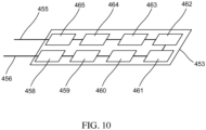
FIG. 10 is a schematic illustration of a thermoelectric cooling module according to an embodiment incorporating a multiplicity of thermoelectric cooling units. -
FIG. 11 is a schematic illustration of electrode clamp device placement geometry in relation to patient anatomy, according to an embodiment. -
FIG. 12 is a schematic illustration of an electrode clamp device according to an embodiment showing electrode heads with large aspect ratio. -
FIG. 13 is a schematic illustration of electrode clamps according to an embodiment with large aspect ratio electrode heads showing overall placement geometry in relation to patient anatomy. -
FIG. 14 is a schematic illustration of an electrode clamp device for irreversible electroporation according to an embodiment, further incorporating means for sensing separation or distance in the form of suitable sensors mounted away from the electrode heads. -
FIG. 15 is a schematic illustration of an electrode clamp device for irreversible electroporation according to an embodiment, further incorporating means for sensing separation or distance in the form of suitable sensors mounted on the electrode heads. - Medical systems, tools and methods are disclosed for the selective and rapid application of DC voltage to drive electroporation. In some embodiments, an apparatus includes a clamp, a first electrode head and a second electrode head. The clamp includes a first arm and a second arm, each configured to exert opposing forces to maintain a target tissue disposed therebetween. The first electrode head is coupled to the first arm. The first electrode head includes a first electrically insulating contact surface, a first electrode and a first cooling unit. The first contact surface is configured to contact a first portion of the target tissue. The first cooling unit is configured to maintain the first portion of the target tissue at a first target temperature. The second electrode head is coupled to the second arm, and includes a second electrically insulating contact surface, a second electrode and a second cooling unit. The second contact surface is configured to contact a second portion of the target tissue. The second cooling unit is configured to maintain the second portion of the target tissue at a second target temperature. The first electrode and the second electrode are collectively configured to deliver a voltage pulse to the target tissue.
- In some embodiments, an apparatus includes a voltage pulse generator configured to produce a pulsed voltage waveform, and an electrode controller. The electrode controller is configured to be operably coupled to the voltage pulse generator and a medical clamp. The medical clamp includes a plurality of electrodes. The electrode controller is implemented in at least one of a memory or a processor, and includes a feedback module, a cooling module and a pulse delivery module. The feedback module is configured to determine a temperature of a target tissue to which the medical clamp is coupled. The cooling module is configured to produce a signal to a cooling unit of the medical clamp to maintain a portion of the target tissue at a target temperature. The pulse delivery module is configured to deliver an output signal associated with the pulsed voltage waveform to the plurality of electrodes.
- In some examples, a non-transitory processor readable medium storing code representing instructions to be executed by a processor includes code to cause the processor to determine a temperature of a target tissue to which a medical clamp is coupled. The medical clamp includes a plurality of electrodes. The code further includes code to produce a signal based at least in part on the temperature of the target tissue. The signal is delivered to a cooling unit of the medical clamp to maintain a portion of the target tissue at a target temperature. The code further includes code to deliver an output signal associated with the pulsed voltage waveform to the plurality of electrodes when the target tissue is at the target temperature.
- In some examples, a method includes receiving, at a feedback module of an electrode controller, a signal associated with a temperature of a target tissue to which a medical clamp is coupled. The medical clamp includes a plurality of electrodes. A signal based at least in part on the temperature of the target tissue is produced. The signal is then delivered to a cooling unit of the medical clamp to maintain a portion of the target tissue at a target temperature. The method includes delivering an output signal associated with the pulsed voltage waveform to the plurality of electrodes when the target tissue is at the target temperature.
- In some embodiments, an irreversible electroporation system includes a DC voltage/signal generator and a controller capable of being configured to apply voltages to a selected multiplicity of electrodes. Further, the controller is capable of applying control inputs whereby selected pairs of anode-cathode subsets of electrodes can be sequentially updated based on a pre-determined sequence. In some embodiments, the controller can further receive at least one temperature input, and based on a temperature input the controller can modify or update a control parameter that can help to maintain a temperature value near a region of interest. The generator can output waveforms that can be selected to generate a sequence of voltage pulses in either monophasic or biphasic forms and with either constant or progressively changing amplitudes.
- Devices are disclosed for the selective electroporation ablation of particular tissue type (e.g., adipose tissue) while preserving surrounding tissue of other types. In some embodiments, the system can include a means for sensing electrode separation, and the electrode voltage applied can be determined based on a sensed separation or distance measure. This determination can be fully or partially automatic, or manual.
- In some embodiments, a system uses temperature to selectively ablate tissue as the threshold of irreversible electroporation is temperature-dependent, utilizing means such as the suitable use of cooling fluid or solid state cooling methods to locally raise the irreversible electroporation threshold electric field value and thereby selecting the predominant tissue type or region it is desired to ablate. In contrast to the process of adipose tissue reduction by freezing, also known as cryogenically induced lipolysis, which uses lower temperatures to directly freeze adipose tissue, the lowered temperatures according to an embodiment assist in the selective action of irreversible electroporation, a much more rapid process than freezing.
- In some embodiments, an irreversible electroporation system includes a DC voltage/signal generator and a controller that is configured to apply voltages to a selected multiplicity or a subset of electrodes. In some embodiments, a temperature measurement device such as a thermistor measures temperature at or near a portion of an electrode device. The controller is capable of applying control inputs whereby the temperature at or near a portion of the device is maintained within a narrow range of desired values. Preferably, the temperature at or near an electrode or electrode head surface contacting a patient anatomy is maintained at or near a value that is lower than body temperature. In some embodiments, the application of DC voltage pulses is made only when the temperature is within a narrow range of values around a desired value. In some embodiments, at least one control input for temperature control takes the form of rate of flow of a cooling fluid, while in another embodiment, the control input is a voltage that drives a thermoelectric heat pump. Further, in some embodiments, the electrode clamp device disclosed here incorporates a sensor to measure a separation distance, based on which the electroporation voltage value is selected.
- A DC voltage for electroporation can be applied to subsets of electrodes identified as anode and cathode respectively on opposite sides of an anatomical region it is desired to ablate. The DC voltage is applied in brief pulses sufficient to cause irreversible electroporation and can preferably be in the range of 0.5 kV to 60 kV and more preferably in the range 1 kV to 10 kV, so that an appropriate threshold electric field value of at least around 800 Volts/cm is effectively achieved in the tissue (for example, adipose tissue) to be ablated. In some embodiments, the DC voltage generator setting for irreversible electroporation is automatically identified by the electroporation system based on a sensed distance measuring the spatial separation between electrodes of opposing polarities. In an alternate embodiment, the DC voltage value is selected directly by a user from a suitable dial, slider, touch screen, or any other user interface. In some embodiments, while transient currents may be induced in the tissue upon voltage application or removal, there are no other (steady state) currents as the electrodes are insulated from the subject anatomy. A region or volume of tissue where the electric field is sufficiently large for irreversible electroporation to occur is ablated during the DC voltage pulse application. At the same time, the application of surface cooling raises the electroporation threshold of tissue near the surface and prevents the occurrence of irreversible electroporation in this surface layer.
- As used in this specification, the singular forms "a," "an" and "the" include plural referents unless the context clearly dictates otherwise. Thus, for example, the term "a member" is intended to mean a single member or a combination of members, "a material" is intended to mean one or more materials, "a processor" is intended to mean a single processor or multiple processors; and "memory" is intended to mean one or more memories, or a combination thereof.
- As used herein, the terms "about" and "approximately" generally mean plus or minus 10% of the value stated. For example, about 0.5 would include 0.45 and 0.55, about 10 would include 9 to 11, about 1000 would include 900 to 1100.
- A schematic diagram of the electroporation system according to an embodiment is shown in
FIG. 1A . The system includes a DC voltage/signal generator 23 is driven by acontroller unit 21 that interfaces with acomputer device 24 by means of a two-way communication link 29. The controller can perform channel selection and routing functions for applying DC voltages to appropriate electrodes that have been selected by a user or by thecomputer 24, and apply the voltages via a multiplicity of leads (shown collectively as 26) to anelectrode device 22. Theelectrode device 22, and any of the electrode devices described herein can be similar to the ablation catheters described inPCT Publication No. WO2014/025394, entitled "Catheters, Catheter Systems, and Methods for Puncturing Through a Tissue Structure," filed on March 14, 2013 ("the '394 PCT Application). - Some of the
leads 26 from thecontroller 21 can also carry control signals to adjust temperature at or near the electrode device. In an alternate embodiment, the control signals from thecontroller 21 can be routed to a different unit (not shown) such as a cooling pump for example, to control cooling fluid flow rate). Theelectrode device 22 can also send information and/or signals to thecontroller 21, such as temperature data from sensors mounted on or near the electrode device. Such feedback signals are indicated by thedata stream 25, which can be sent via separate leads. While theDC voltage generator 23 sends a DC voltage to thecontroller 21 throughleads 27, the voltage generator is driven by control and timinginputs 28 from thecontroller unit 21. - In some embodiments, the electrode controller can include one or more modules and can automatically control the temperature of a target tissue, adjust a characteristic of the voltage waveform based on the spacing between adjacent electrodes, or the like. For example,
FIG. 1B shows an electroporation system according to an embodiment that includes anelectrode controller 900 and asignal generator 925. Theelectrode controller 900 is coupled to acomputer 920 or other input / output device, and is configured to be operably coupled to amedical device 930. Themedical device 930 can be one or more of the medical clamps of the types shown and described herein. Further themedical device 930 can be coupled to, disposed about and/or in contact with a target tissue T. In this manner, as described herein, the electroporation system, including theelectrode controller 900 and thesignal generator 925, can deliver voltage pulses to the target tissue for therapeutic purposes. - The
controller 900 can include amemory 911, aprocessor 910, and an input / output module (or interface) 901. Thecontroller 900 can also include atemperature control module 902, afeedback module 905, and apulse delivery module 908. Theelectrode controller 900 is coupled to acomputer 920 or other input / output device via the input / output module (or interface) 901. - The
processor 910 can be any processor configured to, for example, write data into and read data from thememory 911, and execute the instructions and/or methods stored within thememory 911. Furthermore, theprocessor 910 can be configured to control operation of the other modules within the controller (e.g., thetemperature control module 902, thefeedback module 905, and the pulse delivery module 908). Specifically, theprocessor 910 can receive a signal including user input, temperature data, distance measurements or the like and determine a set of electrodes to which voltage pulses should be applied, the desired timing and sequence of the voltage pulses and the like. In other embodiments, theprocessor 910 can be, for example, an application-specific integrated circuit (ASIC) or a combination of ASICs, which are designed to perform one or more specific functions. In yet other embodiments, the microprocessor can be an analog or digital circuit, or a combination of multiple circuits. - The
memory device 911 can be any suitable device such as, for example, a read only memory (ROM) component, a random access memory (RAM) component, electronically programmable read only memory (EPROM), erasable electronically programmable read only memory (EEPROM), registers, cache memory, and/or flash memory. Any of the modules (thetemperature control module 902, thefeedback module 905, and the pulse delivery module 908) can be implemented by theprocessor 910 and/or stored within thememory 911. - As shown, the
electrode controller 900 operably coupled to thesignal generator 925. The signal generator includes circuitry, components and/or code to produce a series of DC voltage pulses for delivery to electrodes included within themedical device 930. For example, in some embodiments, thesignal generator 925 can be configured to produce a biphasic waveform having a pre-polarizing pulse followed by a polarizing pulse. Thesignal generator 925 can be any suitable signal generator of the types shown and described herein. - The
pulse delivery module 908 of theelectrode controller 900 includes circuitry, components and/or code to deliver an output signal associated with the pulsed voltage waveform produced by thesignal generator 925. This signal (shown as signal 909) can be any signal of the types shown and described herein, and can be of a type and/or have characteristics to be therapeutically effective. In some embodiments, thepulse delivery module 908 receives input from other portions of the system, and can therefore send thesignal 909 to the appropriate subset of electrodes, as described herein. - The
electrode controller 900 includes thetemperature control module 902. Thetemperature control module 902 includes circuitry, components and/or code to produce a control signal (identified as signal 903) that can be delivered to the cooling unit (not shown) of themedical device 930 to facilitate cooling of a portion of the tissue T. - In some examples, the ablation controller and signal generator can be mounted on a rolling trolley, and the user can control the device using a touchscreen interface that could possibly be in the sterile field. The touchscreen can be for example an LCD touchscreen in a plastic housing mountable to a standard medical rail or post and can be used to select the electrodes for ablation and to ready the device to fire. The interface can for example be covered with a clear sterile plastic drape. The operator can select the electrodes involved in an automated sequence, if any. The touch screen graphically shows the catheters that are attached to the controller. In one example the operator can select electrodes from the touchscreen with appropriate graphical buttons. The ablation sequence can be initiated by holding down a hand-held trigger button that is possibly in a sterile field. The hand-held trigger button can be illuminated red to indicate that the device is "armed" and ready to ablate. The trigger button can be compatible for use in a sterile field and when attached to the controller can be illuminated a different color, for example white. In someexamples, the "armed" state of the trigger can depend on whether the electrode temperature is within a desired range of values; if not, an appropriate control signal is applied to bring the temperature back to the desired range. When the device is firing, the trigger button flashes in sequence with the pulse delivery in a specific color such as red. The waveform of each delivered pulse is displayed on the touchscreen interface.
- The waveforms for the various electrodes can be displayed and recorded on the case monitor and simultaneously outputted to a standard data acquisition system. With the high voltages involved with the device, the outputs to the data acquisition system are protected from voltage and/or current surges. The waveform amplitude, period, duty cycle, and delay can all be modified, for example via a suitable Ethernet connection.
- In some embodiments, a system (generator and controller) according to an embodiment can deliver rectangular-wave pulses with a peak maximum voltage of up to about 10 kV into a load with an impedance in the range of 30 Ohm to 3000 Ohm for a maximum duration of 200 µs. In some embodiments the maximum duration can be 100 µs. The load can be part of the electrode circuitry, so that power is harmlessly dissipated in the load. Pulses can be delivered in a multiplexed and synchronized manner to a multi-electrode device with a duty cycle of up to 50 % (for short bursts). The pulses can generally be delivered in bursts, such as for example a sequence of between 2 and 10 pulses interrupted by pauses of between 1 ms and 1000 ms. In one embodiment, the multiplexer controller is capable of running an automated sequence to deliver the impulses/impulse trains (from the DC voltage signal/impulse generator) to the tissue target as a sequence of pulses over electrodes. The controller system is capable of switching between subsets of electrodes located on the electrode device.
- In some embodiments, the controller can have several pulse sequence configurations that provide the operator with at least some variety of programming options. In one configuration, the controller can switch electrode configurations of a bipolar set of electrodes (cathode and anode) sequentially along the length of an electrode clamp device. The user can control the application of DC voltage with a single handheld switch. A sterile catheter or catheters can be connected to the voltage output of the generator via a connector cable. In oneexample, the user activates the device with a touch screen. The generator can remain in a standby mode until the user is ready to apply pulses at which point the user/assistant can put the generator into a ready mode via the touchscreen interface. Subsequently the user can select the sequence and the active electrodes.
- In some embodiments, any of the systems described herein can select an appropriate voltage value based on a distance measurement between electrodes of opposing polarities. In this manner, the system can ensure that an electric field sufficient to cause irreversible electroporation is applied up to the desired depth.
- The controller and generator can output waveforms that can be selected to generate a sequence of voltage pulses in either monophasic or biphasic forms and with either constant or progressively changing amplitudes.
FIG. 2 shows a square or rectangular wave pulse train where thepulses 101 have a uniform height or maximum voltage.FIG. 3 shows an example of a balanced biphasic rectangular pulse train, where each positive voltage pulse such as 103 is immediately followed by a negative voltage pulse such as 104 of equal amplitude and opposite sign. While in this example the biphasic pulses are balanced with equal amplitudes of the positive and negative voltages, in other embodiments an unbalanced biphasic waveform could also be used as may be convenient for a given application. - A train of multiple DC voltage pulses can be applied to ensure that sufficient tissue ablation has occurred. Further, the user can repeat the delivery of irreversible electroporation over several successive pulse trains for further confidence.
- Yet another example of a waveform or pulse shape that can be generated by any of the systems described herein is illustrated in
FIG. 4 , which shows a progressive balanced rectangular pulse train. In this pulse train, each distinct biphasic pulse has equal-amplitude positive and negative voltages, but each pulse such as 107 is larger in amplitude than itsimmediate predecessor 106. Other variations such as a progressive unbalanced rectangular pulse train, or indeed a wide variety of other variations of pulse amplitude with respect to time can be conceived and implemented by those skilled in the art based on the teachings herein. - The time duration of each irreversible electroporation rectangular voltage pulse could lie in the range from 1 nanosecond to 10 milliseconds, with the range 10 microseconds to 1 millisecond being more preferable and the range 50 microseconds to 300 microseconds being still more preferable. The time interval between successive pulses of a pulse train could be in the range of 10 microseconds to 1 millisecond, with the range 50 microseconds to 300 microseconds being more preferable. The number of pulses applied in a single pulse train (with delays between individual pulses lying in the ranges just mentioned) can range from 1 to 100, with the range 1 to 10 being more preferable. As described in the foregoing, a pulse train can be driven by a user-controlled switch or button, in one example preferably mounted on a hand-held joystick-like device. In one mode of operation a pulse train can be generated for every push of such a control button, while in an alternate mode of operation pulse trains can be generated repeatedly during the refractory periods of a set of successive cardiac cycles, for as long as the user-controlled switch or button is engaged by the user.
- All of these parameters can be determined by the design of the signal generator, and in various embodiments could also be determined by user control as may be convenient for a given clinical application. The specific examples and descriptions herein are exemplary in nature and variations can be developed by those skilled in the art based on the material taught herein without departing from the scope according to an embodiment, which is limited only by the attached claims.
- In some embodiments, an irreversible electroporation ablation system of the type shown and described herein can be used for adipose tissue (or fat) ablation for the reduction or elimination of adipose tissue. As mentioned earlier, various tissue or cell types have different irreversible electroporation thresholds. Fat cells typically have an irreversible electroporation threshold in the range of 800 Volts/cm.
FIG. 5 shows an electrode clamp device that externally clamps onto a fold of skin on a patient anatomy, with electrode clamparms 211 connected to aclamp head 210 including springs, screw or other tightening mechanisms for firmly positioning the electrodes in a clamped position. The electrode clamp arms end in electrode heads 212 that incorporate coolingcoils 219 that carry a cooling fluid at a temperature sufficient to cool and maintain the skin temperature at about approximately 13 degrees Celsius (50 degrees Fahrenheit). A cooling system and drive pump (not shown) with a controllable fluid flow rate supply coolant to maintain the electrode temperature at or near a suitably low value (such as, for example, 13 degrees Celsius (50 degrees Fahrenheit)). The electrodes are shown clamping on to tissue in the form of a layer ofskin 215 withfatty tissue 214 beneath the skin. Each electrode itself is located internally within its electrode head and the latter is made of insulating material, so that no conductor touches the patient surface.FIG. 5 shows an example ofelectric field lines 217 generated in the tissue when a DC voltage is applied across the electrodes. - As shown in
FIG. 5 , since the patient-contacting surfaces are insulators, there is no steady state charge transfer or direct current within the tissue. However, the polarizing electric field applied in pulses can generate irreversible electroporation in the tissue and generate induced or transient currents in the tissue. The irreversible electroporation threshold of tissue increases as temperature decreases. Thus, by cooling the electrodes and the layer of skin, the skin tissue's electroporation threshold can be increased beyond the approximately 800 V/cm threshold value of fat tissue. When a DC electric field of suitable strength is applied, fat (indicated by 214 inFIG. 5 ) can therefore be selectively ablated by electroporation while maintaining the integrity of skin tissue (indicated by 215 inFIG. 5 ) as long as the applied electric field is in the range between the irreversible electroporation thresholds of adipose tissue and the cooled skin tissue. -
FIG. 6 is a schematic illustration of an electrode head of the electrode clamp device showing the electrodes or electroporation probes 233 situated within anouter casing 231. Coolant coils 235 within each electrode head keep the electrode head surface cold and maintain the skin temperature at approximately 13 degrees Celsius (50 degrees Fahrenheit). The patient-contactingsurface 239 of each electrode head is an insulator, so that there is no direct current transfer between the electrodes. The parallel electrodes act like capacitor plates for very brief periods as DC voltage pulses are applied for irreversible electroporation. Theelectric field 237 generated between the electrodes in the tissue region serves to polarize the tissue and generate irreversible electroporation in the fat or adipose tissue. The voltage pulses induce brief transient currents in the tissue when the field changes but no steady state direct current. Thus with this device, inductive irreversible electroporation can be generated. The applied DC voltage can be made to depend on the distance between the electrodes. In one embodiment, the electrode clamp can have a discrete number of possible relative positions of the electrodes with pre-determined separation distances. Based on the separation, a sufficient voltage that generates at least an approximately 800 Volts/cm electric field between the electrodes can be computed by the electroporation system and applied for the selective irreversible electroporation of adipose tissue. -
FIG. 7 shows an electrode clamp device that externally clamps onto a fold of skin on a patient anatomy, with electrode clamparms clamp head 314 including ascrew mechanism 319 for firmly positioning the electrodes in a clamped position around a portion of patient anatomy, with a fixed distance between electrode arms. Thetop electrode arm 301 has disposed along it electrode heads 305, 306 and 307 respectively aligned with electrode heads 315, 316 and 317 on thebottom electrode arm 302. InFIG. 7 , thelower electrode arm 302 is fixed to a mount (not shown) and the screw mechanism allows for the vertical motion ofelectrode arm 301 relative toelectrode arm 302, thereby permitting adjustment of the separation distance between the arms over a range of values. In some embodiments, the electrode heads can incorporate thermoelectric cooling modules for keeping the patient-contacting face of each electrode at a cooled temperature significantly below body temperature (for example, the patient contacting face of the electrode can be maintained in a narrow range around 13 degrees Celsius (50 degrees Fahrenheit)). This can be done with a thermoelectric or solid state cooling module by applying an appropriate voltage or current to the cooling module. Solid state cooling has the advantage of having no moving parts with corresponding convenience of design and implementation. - As an example, referring to
FIG. 7 bipolar leads 310, 311 and 312 attach to electrodeheads thermistor 297 shown attached to leads 298 onelectrode arm 302. The data from the temperature sensing unit is read by the controller (not shown inFIG. 7 ) or to a computer where the temperature data is utilized to generate an appropriate control signal for the purpose of maintaining electrode face temperature by using any of a range of control schemes or methods, for example PID (Proportional-Integral-Derivative) control. -
FIG. 8 is a schematic illustration of an electrode head incorporating means for solid state or thermoelectric cooling. Ametal electrode 332 for high voltage DC application abuts aceramic cover 333 on one side (with the outside face of the ceramic cover being a patient contacting face) and a thermoelectric orPeltier cooling module 331 on the other. The top face of thecooling module 331 is adjacent to aceramic cover 330, so that the entire electrode head has ceramic faces on both top and bottom faces. -
FIG. 9 schematically illustrates a thermoelectric or Peltier cooling unit, a multiplicity of which can be arranged to form a Peltier cooling module. The thermoelectric unit comprises a p-type semiconductor 401 (such as for example Lead Telluride) electrically in series with an n-type semiconductor 402 (such as for example Bismuth Telluride) and connected by ametallic connection 404. At the same time, thesemiconductors terminal electrodes electrodes ceramic cover 408. When a voltage is applied to the terminal electrodes (so that terminal 406 is at a negative electric potential relative to terminal 407), a current flows from the n-type semiconductor 402 through theseries connection 404 and through the p-type semiconductor 401. The respective charge carriers in each semiconductor move from the top to the bottom, and correspondingly there is a heat flux that transports heat from thetop face 404 of the Peltier cooling unit to thebottom face 408. Correspondingly 404 is turned into the "cold" or lower temperature face and 408 into the "hot" or higher temperature face of the Peltier cooling unit. -
FIG. 10 schematically depicts a chain of Peltier cooling units connected to form a thermoelectric cooling module. In this example, themodule 453 comprisesPeltier cooling units - Thermoelectric heat pump modules are commercially available, for example from sources such as TE Technology, Inc. of Traverse City, Michigan, USA and appropriate configurations convenient for the electrode clamp devices according to an embodiment can be arrived at by those skilled in the art.
-
FIG. 11 schematically illustrates one geometry of use of the electrode clamp device, wherein aportion 347 of skin andadipose tissue 342 disposed around apatient anatomy 341 is clamped betweenelectrode arms FIG. 12 is an illustration of an electrode clamp device withelectrode arms FIG. 13 , such an arrangement could be used to clamp, in a lengthwise disposition, a portion of skin andadipose tissue 342 disposed around apatient anatomy 341 betweenelectrode arms - In some embodiments, the time for which a cold temperature is maintained at the patient contacting surface of the electrode head is monitored and varied, so that the cooling control is applied in time in a pulse-like format. This is done in order to maintain a surface layer of tissue at a suitably low or cold temperature, while ensuring that deeper regions of tissue undergo no more than marginal cooling. The thermal diffusivity D of skin tissue is known to be in the range of 0.11 mm2/s. From standard heat diffusion theory, in a time T the depth x to which a temperature change applied at the surface is propagated is given (in two dimensions) by

-
FIG. 14 illustrates schematically one embodiment, where the electrode clamp device withelectrode arms electromagnetic transmitter 352 onelectrode arm 302 and anelectromagnetic receiver coil 350 onelectrode arm 301.Leads receiver 350 andtransmitter 352. Based on the signal intensity received by thereceiver 350, the distance of separation d indicated by 355 in the FIG. can be measured. For example, if the axes and centers of the transmitter and receiver sensors are aligned, and a current I flows through the transmitter (of radius a), the magnetic field B at the center of the receiver is given by

- While in
FIG. 14 the transmitter and receiver sensors for distance determination were located at a separation away from the electrode heads to mitigate electromagnetic interference with the metallic electrodes, in an alternate embodiment, the transmitter and receiver sensors could be integrated within an electrode head, as shown schematically inFIG. 15 . InFIG. 15 , thetransmitter 352 is incorporated inelectrode head 315 oflower electrode arm 302, whilereceiver sensor 350 is incorporated inelectrode head 305 ofupper electrode arm 301. Also shown are other electrode heads 306, 307, 316 and 317. With this arrangement, the induced voltage at the receiver is calibrated over a range of separations of the electrode arms, in effect generating a lookup table. The electromagnetic interference of the electrode heads is implicitly accounted for by this calibration process; subsequently, given a measured induced voltage at the receiver, the separation distance can be determined from the calibration data. - While the foregoing described one method of separation distance determination based on an electromagnetic scheme purely for illustrative and exemplary purposes, it should be apparent that a variety of other methods are available for this purpose such as for example schemes based on the use of ultrasound transmitters and receivers or infrared transmitters and receivers. Based on the teachings herein, those skilled in the art could arrive at an implementation that may be convenient for a specific application.
- With a separation distance between electrode heads thus determined, the applied voltage to the electrode heads is then correspondingly determined based on a desired irreversible electroporation threshold value. For example, if the distance between electrode heads is measured to be 4 cm, and the desired irreversible electroporation threshold value is an electric field of 800 Volts/cm, it is clear that a voltage of at least 3.2 kV (desired electric field times distance) needs to be applied between the electrodes in order to meet or exceed the threshold value for irreversible electroporation.
- Some examples described herein relate to a computer storage product with a non-transitory computer-readable medium (also can be referred to as a non-transitory processor-readable medium) having instructions or computer code thereon for performing various computer-implemented operations. The computer-readable medium (or processor-readable medium) is non-transitory in the sense that it does not include transitory propagating signals per se (e.g., a propagating electromagnetic wave carrying information on a transmission medium such as space or a cable). The media and computer code (also can be referred to as code) may be those designed and constructed for the specific purpose or purposes. Examples of non-transitory computer-readable media include, but are not limited to: magnetic storage media such as hard disks, floppy disks, and magnetic tape; optical storage media such as Compact Disc/Digital Video Discs (CD/DVDs), Compact Disc-Read Only Memories (CD-ROMs), and holographic devices; magneto-optical storage media such as optical disks; carrier wave signal processing modules; and hardware devices that are specially configured to store and execute program code, such as Application-Specific Integrated Circuits (ASICs), Programmable Logic Devices (PLDs), Read-Only Memory (ROM) and Random-Access Memory (RAM) devices.
- Examples of computer code include, but are not limited to, micro-code or micro-instructions, machine instructions, such as produced by a compiler, code used to produce a web service, and files containing higher-level instructions that are executed by a computer using an interpreter. For example, embodiments may be implemented using imperative programming languages (e.g., C, Fortran, etc.), functional programming languages (Haskell, Erlang, etc.), logical programming languages (e.g., Prolog), object-oriented programming languages (e.g., Java, C++, etc.) or other suitable programming languages and/or development tools. Additional examples of computer code include, but are not limited to, control signals, encrypted code, and compressed code.
- While various specific examples and embodiments of systems and tools for selective tissue ablation with irreversible electroporation were described in the foregoing for illustrative and exemplary purposes, it should be clear that a wide variety of variations and alternate embodiments could be conceived or constructed by those skilled in the art based on the teachings according to the disclosure. While specific methods of control and DC voltage application from a generator capable of selective excitation of sets of electrodes were disclosed together with temperature control, persons skilled in the art would recognize that any of a wide variety of other control or user input methods can be implemented. Likewise, while the foregoing described a range of specific tools or devices for more effective and selective DC voltage application for irreversible electroporation through an externally applied electrode clamp device, other device constructions or variations could be implemented by one skilled in the art by employing the principles and teachings disclosed herein in the treatment of excessive adipose tissue, tumor ablation, or a variety of other medical applications.
- Furthermore, while the present disclosure describes specific embodiments and tools involving the use of temperature to selectively ablate tissue by taking advantage of the temperature-dependence of the threshold of irreversible electroporation and the application of specific cooling methodologies for exemplary purposes, it should be clear to one skilled in the art that a variety of methods and devices for fluid pumping and control, for tissue or electrode cooling, or even for tissue heating through the delivery of focused kinetic energy or electromagnetic radiation could be implemented utilizing the methods and principles taught herein.
- Accordingly, while many variations of methods and tools disclosed here can be constructed, the scope of the invention is limited only by the appended claims.
Claims (15)
- An apparatus, comprising:a clamp including a first arm (211) and a second arm (211), the first arm and the second arm configured to exert opposing forces to maintain a target tissue disposed between the first arm and the second arm;a first electrode head (212) coupled to the first arm, the first electrode head including a first electrically insulating contact surface (239), a first electrode (233) and a first cooling unit (219), the first contact surface configured to contact a first portion of the target tissue, the first cooling unit configured to maintain the first portion of the target tissue at a first target temperature; anda second electrode head (212) coupled to the second arm, the second electrode head including a second electrically insulating contact surface (239), a second electrode (233) and a second cooling unit (219), the second contact surface configured to contact a second portion of the target tissue, the second cooling unit configured to maintain the second portion of the target tissue at a second target temperature, characterized in thatthe first electrode and the second electrode collectively configured to deliver a DC voltage pulse waveform configured to irreversibly electroporate the target tissue with no direct current transfer between the electrodes.
- The apparatus of claim 1, wherein at least one of the first target temperature or the second target temperature is about 13 degrees Celsius (55 degrees Fahrenheit) or less.
- The apparatus of claim 1, wherein at least one of the first cooling unit or the second cooling unit is any one of a cooling coil, a thermo-electric cooler or a heat pump.
- The apparatus of claim 1, wherein the first electrode head includes a sensor configured to measure a temperature of the first portion of the target tissue.
- The apparatus of claim 1, wherein the clamp is configured to maintain a distance between the first electrode head and the second electrode head within a predetermined range.
- The apparatus of claim 1, wherein the clamp includes an adjustment member configured to adjust a distance between the first electrode head and the second electrode head.
- The apparatus of claim 1, further comprising:
a sensor configured to produce a distance signal associated with a distance between the first electrode head and the second electrode head. - The apparatus of claim 7, wherein the sensor is any one of an electromagnetic sensor or an ultrasound sensor.
- The apparatus of claim 1, wherein the first electrode head includes a temperature sensor configured to measure a temperature of the first portion of the target tissue, the apparatus further comprising:
a sensor configured to produce a distance signal associated with a distance between the first electrode head and the second electrode head. - The apparatus of claim 1, wherein the first arm and the second arm define a volume to receive a target tissue, the first cooling unit is configured to cool the first portion of the target tissue to the first temperature below a body temperature and the second cooling unit is configured to cool the second portion of the target tissue to the second temperature below the body temperature.
- The apparatus of claim 1, further comprising:a voltage pulse generator (23, 925) configured to produce a pulsed voltage waveform; andan electrode controller (21, 900) configured to be operably coupled to the voltage pulse generator and the clamp, the electrode controller implemented in at least one of a memory (911) or a processor (910), the electrode controller including a feedback module (905), a cooling module (902) and a pulse delivery module (908),the feedback module configured to determine a temperature of the target tissue to which the clamp is coupled, the cooling module configured to produce a signal to the first and second cooling units of the clamp to maintain the first and second portions of the target tissue at the first and second target temperatures, respectively, the pulse delivery module configured to deliver an output signal associated with the pulsed voltage waveform to the first and second electrodes.
- The apparatus of claim 11, wherein the electrode controller is configured to interface with an external device to program at least one of an amplitude of the output signal, a period of the output signal, or a duration of the output signal.
- The apparatus of claim 11, wherein the cooling module is configured to produce the signal based at least in part on the temperature of the target tissue.
- The apparatus of claim 11, wherein:the first arm is spaced apart from the second arm by a distance;the feedback module is configured to receive a distance signal associated with the distance; andthe pulse delivery module is configured to adjust a characteristic of the output signal based on the distance.
- The apparatus of claim 14, wherein the characteristic of the output signal is any one of an amplitude of the output signal, a period of the output signal, or duration of the output signal.
Priority Applications (1)
| Application Number | Priority Date | Filing Date | Title |
|---|---|---|---|
| EP25154836.8A EP4559428A3 (en) | 2014-06-12 | 2015-06-12 | Method and apparatus for rapid and selective tissue ablation with cooling |
Applications Claiming Priority (2)
| Application Number | Priority Date | Filing Date | Title |
|---|---|---|---|
| US201461997869P | 2014-06-12 | 2014-06-12 | |
| PCT/US2015/035582 WO2015192018A1 (en) | 2014-06-12 | 2015-06-12 | Method and apparatus for rapid and selective tissue ablation with cooling |
Related Child Applications (2)
| Application Number | Title | Priority Date | Filing Date |
|---|---|---|---|
| EP25154836.8A Division-Into EP4559428A3 (en) | 2014-06-12 | 2015-06-12 | Method and apparatus for rapid and selective tissue ablation with cooling |
| EP25154836.8A Division EP4559428A3 (en) | 2014-06-12 | 2015-06-12 | Method and apparatus for rapid and selective tissue ablation with cooling |
Publications (3)
| Publication Number | Publication Date |
|---|---|
| EP3154464A1 EP3154464A1 (en) | 2017-04-19 |
| EP3154464A4 EP3154464A4 (en) | 2018-01-24 |
| EP3154464B1 true EP3154464B1 (en) | 2025-03-12 |
Family
ID=54834407
Family Applications (2)
| Application Number | Title | Priority Date | Filing Date |
|---|---|---|---|
| EP15806855.1A Active EP3154464B1 (en) | 2014-06-12 | 2015-06-12 | Apparatus for rapid and selective tissue ablation with cooling |
| EP25154836.8A Pending EP4559428A3 (en) | 2014-06-12 | 2015-06-12 | Method and apparatus for rapid and selective tissue ablation with cooling |
Family Applications After (1)
| Application Number | Title | Priority Date | Filing Date |
|---|---|---|---|
| EP25154836.8A Pending EP4559428A3 (en) | 2014-06-12 | 2015-06-12 | Method and apparatus for rapid and selective tissue ablation with cooling |
Country Status (3)
| Country | Link |
|---|---|
| US (3) | US10624693B2 (en) |
| EP (2) | EP3154464B1 (en) |
| WO (1) | WO2015192018A1 (en) |
Families Citing this family (54)
| Publication number | Priority date | Publication date | Assignee | Title |
|---|---|---|---|---|
| AU2012221758B2 (en) | 2011-02-24 | 2017-05-04 | Eximo Medical Ltd. | Hybrid catheter for tissue resection |
| WO2014025394A1 (en) | 2012-08-09 | 2014-02-13 | University Of Iowa Research Foundation | Catheters, catheter systems, and methods for puncturing through a tissue structure |
| US12514456B2 (en) | 2013-01-31 | 2026-01-06 | Eximo Medical Ltd. | System and methods for lesion characterization in blood vessels |
| EP3091921B1 (en) | 2014-01-06 | 2019-06-19 | Farapulse, Inc. | Apparatus for renal denervation ablation |
| EP4670627A2 (en) | 2014-05-07 | 2025-12-31 | Boston Scientific Scimed, Inc. | METHOD AND DEVICE FOR SELECTIVE TISSUE ABSORPTION |
| EP3142584A1 (en) | 2014-05-16 | 2017-03-22 | Iowa Approach Inc. | Methods and apparatus for multi-catheter tissue ablation |
| WO2015177790A1 (en) | 2014-05-18 | 2015-11-26 | Eximo Medical Ltd. | System for tissue ablation using pulsed laser |
| EP3154464B1 (en) | 2014-06-12 | 2025-03-12 | Boston Scientific Scimed, Inc. | Apparatus for rapid and selective tissue ablation with cooling |
| WO2015192027A1 (en) | 2014-06-12 | 2015-12-17 | Iowa Approach Inc. | Method and apparatus for rapid and selective transurethral tissue ablation |
| WO2016060983A1 (en) | 2014-10-14 | 2016-04-21 | Iowa Approach Inc. | Method and apparatus for rapid and safe pulmonary vein cardiac ablation |
| EP3331604B1 (en) | 2015-08-06 | 2021-09-29 | Medtronic, Inc. | Cardiac pulsed field ablation |
| US12144541B2 (en) | 2016-01-05 | 2024-11-19 | Boston Scientific Scimed, Inc. | Systems, apparatuses and methods for delivery of ablative energy to tissue |
| US10130423B1 (en) | 2017-07-06 | 2018-11-20 | Farapulse, Inc. | Systems, devices, and methods for focal ablation |
| US10172673B2 (en) | 2016-01-05 | 2019-01-08 | Farapulse, Inc. | Systems devices, and methods for delivery of pulsed electric field ablative energy to endocardial tissue |
| EP3399933B1 (en) * | 2016-01-05 | 2021-09-01 | Farapulse, Inc. | Systems for delivery of pulsed electric field ablative energy to endocardial tissue |
| US10660702B2 (en) | 2016-01-05 | 2020-05-26 | Farapulse, Inc. | Systems, devices, and methods for focal ablation |
| US20170189097A1 (en) | 2016-01-05 | 2017-07-06 | Iowa Approach Inc. | Systems, apparatuses and methods for delivery of ablative energy to tissue |
| CN109414292A (en) | 2016-05-05 | 2019-03-01 | 爱克斯莫医疗有限公司 | Device and method for cutting off and/or melting unwanted tissue |
| EP3471631A4 (en) | 2016-06-16 | 2020-03-04 | Farapulse, Inc. | GUIDE WIRE DISTRIBUTION SYSTEMS, APPARATUSES AND METHODS |
| EP3474760B1 (en) | 2016-06-27 | 2023-01-11 | Galvanize Therapeutics, Inc. | Generator and a catheter with an electrode for treating a lung passageway |
| US12403305B2 (en) | 2016-06-27 | 2025-09-02 | Galvanize Therapeutics, Inc. | Immunostimulation in the treatment of viral infection |
| KR102599298B1 (en) * | 2016-09-23 | 2023-11-07 | 이노비오 파마수티컬즈, 인크. | Method and device for minimally invasive in vivo transfection of adipose tissue using electroporation |
| WO2018167877A1 (en) * | 2017-03-15 | 2018-09-20 | オリンパス株式会社 | Energy source device |
| US9987081B1 (en) | 2017-04-27 | 2018-06-05 | Iowa Approach, Inc. | Systems, devices, and methods for signal generation |
| US10617867B2 (en) | 2017-04-28 | 2020-04-14 | Farapulse, Inc. | Systems, devices, and methods for delivery of pulsed electric field ablative energy to esophageal tissue |
| CN111065327B (en) | 2017-09-12 | 2023-01-06 | 波士顿科学医学有限公司 | Systems, devices, and methods for ventricular focal ablation |
| WO2019108664A2 (en) | 2017-11-28 | 2019-06-06 | St. Jude Medical, Cardiology Division, Inc. | Controllable expandable catheter |
| EP4275738B1 (en) | 2018-02-08 | 2025-12-17 | Boston Scientific Scimed, Inc. | Apparatus for controlled delivery of pulsed electric field ablative energy to tissue |
| US20190336198A1 (en) * | 2018-05-03 | 2019-11-07 | Farapulse, Inc. | Systems, devices, and methods for ablation using surgical clamps |
| CN112118798B (en) | 2018-05-07 | 2024-09-20 | 波士顿科学医学有限公司 | Systems, devices and methods for filtering high voltage noise induced by pulsed electric field ablation |
| EP3790485B1 (en) | 2018-05-07 | 2024-06-26 | Boston Scientific Scimed, Inc. | Epicardial ablation catheter |
| CN112087980B (en) | 2018-05-07 | 2023-01-10 | 波士顿科学医学有限公司 | Systems, devices, and methods for delivering ablation energy to tissue |
| CN119184833A (en) | 2018-09-20 | 2024-12-27 | 波士顿科学医学有限公司 | Systems, devices, and methods for delivering pulsed electric field ablation energy to endocardial tissue |
| US10625080B1 (en) | 2019-09-17 | 2020-04-21 | Farapulse, Inc. | Systems, apparatuses, and methods for detecting ectopic electrocardiogram signals during pulsed electric field ablation |
| US11065047B2 (en) | 2019-11-20 | 2021-07-20 | Farapulse, Inc. | Systems, apparatuses, and methods for protecting electronic components from high power noise induced by high voltage pulses |
| US11497541B2 (en) | 2019-11-20 | 2022-11-15 | Boston Scientific Scimed, Inc. | Systems, apparatuses, and methods for protecting electronic components from high power noise induced by high voltage pulses |
| US10842572B1 (en) | 2019-11-25 | 2020-11-24 | Farapulse, Inc. | Methods, systems, and apparatuses for tracking ablation devices and generating lesion lines |
| JP7547500B2 (en) * | 2020-04-09 | 2024-09-09 | バード・ペリフェラル・バスキュラー・インコーポレーテッド | Systems and methods for using a multi-probe integrated electro-thermal module (ETM) device for tumor ablation - Patents.com |
| EP4157124A1 (en) * | 2020-06-02 | 2023-04-05 | Pulse Biosciences, Inc. | High-voltage minimally invasive applicator devices for sub-microsecond pulsing |
| WO2022020478A1 (en) | 2020-07-24 | 2022-01-27 | Boston Scientific Scimed Inc | Electric field application for single shot cardiac ablation by irreversible electroporation |
| US12310652B2 (en) | 2020-07-24 | 2025-05-27 | Boston Scientific Scimed, Inc. | Hybrid electroporation ablation catheter |
| US12076071B2 (en) | 2020-08-14 | 2024-09-03 | Kardium Inc. | Systems and methods for treating tissue with pulsed field ablation |
| US12376904B1 (en) | 2020-09-08 | 2025-08-05 | Angiodynamics, Inc. | Dynamic laser stabilization and calibration system |
| JP7617250B2 (en) | 2020-09-08 | 2025-01-17 | ボストン サイエンティフィック サイムド,インコーポレイテッド | Contoured electrodes for pulsed electric field ablation and systems, devices and methods thereof - Patents.com |
| JP7564353B2 (en) | 2020-09-30 | 2024-10-08 | ボストン サイエンティフィック サイムド,インコーポレイテッド | Pretreatment waveforms for irreversible electroporation |
| JP7764483B2 (en) | 2021-01-27 | 2025-11-05 | ボストン サイエンティフィック サイムド,インコーポレイテッド | Voltage-controlled pulse sequences for irreversible electroporation ablation |
| CA3214189A1 (en) | 2021-04-07 | 2022-10-13 | Vojtech NEDVED | Pulsed field ablation device and method |
| WO2023280822A1 (en) | 2021-07-06 | 2023-01-12 | Btl Medical Technologies S.R.O. | Pulsed field ablation device and method |
| US20230079700A1 (en) * | 2021-09-13 | 2023-03-16 | Intelis Instruments Ltd. | Double Monopolar RF Body Contouring |
| US12038322B2 (en) * | 2022-06-21 | 2024-07-16 | Eximo Medical Ltd. | Devices and methods for testing ablation systems |
| CN115501485A (en) * | 2022-09-20 | 2022-12-23 | 威脉清通医疗科技(无锡)有限公司 | Radio frequency system and radio frequency processing method |
| JP2025533070A (en) | 2022-10-05 | 2025-10-03 | ビーティーエル メディカル デベロップメント エー.エス. | Pulsed field ablation device and method |
| WO2025212782A1 (en) | 2024-04-03 | 2025-10-09 | Field Medical, Inc. | Systems and methods for affecting a target tissue via a pulsed field |
| CN119157629B (en) * | 2024-09-18 | 2025-10-03 | 深圳市同源生物医疗科技有限公司 | Medical electrode clamp power indication method, device and medical electrode clamp |
Citations (2)
| Publication number | Priority date | Publication date | Assignee | Title |
|---|---|---|---|---|
| US20090062792A1 (en) * | 2007-08-31 | 2009-03-05 | Ethicon Endo-Surgery, Inc. | Electrical ablation surgical instruments |
| WO2014008489A1 (en) * | 2012-07-04 | 2014-01-09 | Cibiem, Inc. | Devices and systems for carotid body ablation |
Family Cites Families (587)
| Publication number | Priority date | Publication date | Assignee | Title |
|---|---|---|---|---|
| US4200104A (en) | 1977-11-17 | 1980-04-29 | Valleylab, Inc. | Contact area measurement apparatus for use in electrosurgery |
| US4470407A (en) | 1982-03-11 | 1984-09-11 | Laserscope, Inc. | Endoscopic device |
| US4739759A (en) | 1985-02-26 | 1988-04-26 | Concept, Inc. | Microprocessor controlled electrosurgical generator |
| US5547467A (en) | 1988-01-21 | 1996-08-20 | Massachusettes Institute Of Technology | Method for rapid temporal control of molecular transport across tissue |
| US5344435A (en) | 1988-07-28 | 1994-09-06 | Bsd Medical Corporation | Urethral inserted applicator prostate hyperthermia |
| FR2639238B1 (en) | 1988-11-21 | 1991-02-22 | Technomed Int Sa | APPARATUS FOR SURGICAL TREATMENT OF TISSUES BY HYPERTHERMIA, PREFERABLY THE PROSTATE, COMPRISING MEANS OF THERMAL PROTECTION COMPRISING PREFERABLY RADIOREFLECTIVE SCREEN MEANS |
| US5257635A (en) | 1988-11-25 | 1993-11-02 | Sensor Electronics, Inc. | Electrical heating catheter |
| US5749914A (en) | 1989-01-06 | 1998-05-12 | Advanced Coronary Intervention | Catheter for obstructed stent |
| US5342301A (en) | 1992-08-13 | 1994-08-30 | Advanced Polymers Incorporated | Multi-lumen balloons and catheters made therewith |
| WO1992021285A1 (en) | 1991-05-24 | 1992-12-10 | Ep Technologies, Inc. | Combination monophasic action potential/ablation catheter and high-performance filter system |
| US6029671A (en) | 1991-07-16 | 2000-02-29 | Heartport, Inc. | System and methods for performing endovascular procedures |
| US5697281A (en) | 1991-10-09 | 1997-12-16 | Arthrocare Corporation | System and method for electrosurgical cutting and ablation |
| US5524338A (en) | 1991-10-22 | 1996-06-11 | Pi Medical Corporation | Method of making implantable microelectrode |
| US5304214A (en) | 1992-01-21 | 1994-04-19 | Med Institute, Inc. | Transurethral ablation catheter |
| US5306296A (en) | 1992-08-21 | 1994-04-26 | Medtronic, Inc. | Annuloplasty and suture rings |
| US5242441A (en) | 1992-02-24 | 1993-09-07 | Boaz Avitall | Deflectable catheter with rotatable tip electrode |
| US5281213A (en) * | 1992-04-16 | 1994-01-25 | Implemed, Inc. | Catheter for ice mapping and ablation |
| US5443463A (en) | 1992-05-01 | 1995-08-22 | Vesta Medical, Inc. | Coagulating forceps |
| US20050222632A1 (en) | 1992-05-17 | 2005-10-06 | Obino Stan F | Device and method for the treatment of cardiac disorders |
| US5341807A (en) | 1992-06-30 | 1994-08-30 | American Cardiac Ablation Co., Inc. | Ablation catheter positioning system |
| US5313943A (en) | 1992-09-25 | 1994-05-24 | Ep Technologies, Inc. | Catheters and methods for performing cardiac diagnosis and treatment |
| US5700243A (en) | 1992-10-30 | 1997-12-23 | Pdt Systems, Inc. | Balloon perfusion catheter |
| US5334193A (en) | 1992-11-13 | 1994-08-02 | American Cardiac Ablation Co., Inc. | Fluid cooled ablation catheter |
| US6068653A (en) | 1992-11-13 | 2000-05-30 | Scimed Life Systems, Inc. | Electrophysiology catheter device |
| US5545161A (en) | 1992-12-01 | 1996-08-13 | Cardiac Pathways Corporation | Catheter for RF ablation having cooled electrode with electrically insulated sleeve |
| US6749604B1 (en) | 1993-05-10 | 2004-06-15 | Arthrocare Corporation | Electrosurgical instrument with axially-spaced electrodes |
| US5531685A (en) | 1993-06-11 | 1996-07-02 | Catheter Research, Inc. | Steerable variable stiffness device |
| FR2708860B1 (en) | 1993-08-11 | 1995-10-13 | Ela Medical Sa | Protection circuit for implantable electronic device. |
| US5545193A (en) | 1993-10-15 | 1996-08-13 | Ep Technologies, Inc. | Helically wound radio-frequency emitting electrodes for creating lesions in body tissue |
| US5722400A (en) | 1995-02-16 | 1998-03-03 | Daig Corporation | Guiding introducers for use in the treatment of left ventricular tachycardia |
| US5921924A (en) | 1993-12-03 | 1999-07-13 | Avitall; Boaz | Mapping and ablation catheter system utilizing multiple control elements |
| US5454370A (en) | 1993-12-03 | 1995-10-03 | Avitall; Boaz | Mapping and ablation electrode configuration |
| US5928269A (en) | 1994-04-04 | 1999-07-27 | Alt; Eckhard | Apparatus and method for temporary atrial defibrillation with external defibrillator and implanted transvenous catheter and electrodes |
| US5578040A (en) | 1994-06-14 | 1996-11-26 | Smith; Albert C. | Ocular repair system and apparatus |
| US5617854A (en) | 1994-06-22 | 1997-04-08 | Munsif; Anand | Shaped catheter device and method |
| US6071274A (en) | 1996-12-19 | 2000-06-06 | Ep Technologies, Inc. | Loop structures for supporting multiple electrode elements |
| US5885278A (en) | 1994-10-07 | 1999-03-23 | E.P. Technologies, Inc. | Structures for deploying movable electrode elements |
| US5836947A (en) | 1994-10-07 | 1998-11-17 | Ep Technologies, Inc. | Flexible structures having movable splines for supporting electrode elements |
| US5876336A (en) | 1994-10-11 | 1999-03-02 | Ep Technologies, Inc. | Systems and methods for guiding movable electrode elements within multiple-electrode structure |
| US5722402A (en) | 1994-10-11 | 1998-03-03 | Ep Technologies, Inc. | Systems and methods for guiding movable electrode elements within multiple-electrode structures |
| US5624430A (en) | 1994-11-28 | 1997-04-29 | Eton; Darwin | Magnetic device to assist transcorporeal guidewire placement |
| US5647871A (en) * | 1995-03-10 | 1997-07-15 | Microsurge, Inc. | Electrosurgery with cooled electrodes |
| US5810762A (en) * | 1995-04-10 | 1998-09-22 | Genetronics, Inc. | Electroporation system with voltage control feedback for clinical applications |
| US6090104A (en) | 1995-06-07 | 2000-07-18 | Cordis Webster, Inc. | Catheter with a spirally wound flat ribbon electrode |
| US20060024359A1 (en) | 1995-06-07 | 2006-02-02 | Walker Jeffrey P | Drug delivery system and method |
| US5702438A (en) | 1995-06-08 | 1997-12-30 | Avitall; Boaz | Expandable recording and ablation catheter system |
| US5788692A (en) | 1995-06-30 | 1998-08-04 | Fidus Medical Technology Corporation | Mapping ablation catheter |
| US6023638A (en) | 1995-07-28 | 2000-02-08 | Scimed Life Systems, Inc. | System and method for conducting electrophysiological testing using high-voltage energy pulses to stun tissue |
| US5706823A (en) | 1995-08-18 | 1998-01-13 | Quinton Instrument Company | Electrophysiology filtering system |
| US5836875A (en) | 1995-10-06 | 1998-11-17 | Cordis Webster, Inc. | Split tip electrode catheter |
| DE29519651U1 (en) | 1995-12-14 | 1996-02-01 | Muntermann, Axel, 35583 Wetzlar | Device for linear radio frequency catheter ablation of endomyocardial tissue |
| BR9612395A (en) | 1995-12-29 | 1999-07-13 | Gyrus Medical Ltd | Electrosurgical instrument and an electrosurgical electrode set |
| US7141049B2 (en) | 1999-03-09 | 2006-11-28 | Thermage, Inc. | Handpiece for treatment of tissue |
| US5836874A (en) | 1996-04-08 | 1998-11-17 | Ep Technologies, Inc. | Multi-function electrode structures for electrically analyzing and heating body tissue |
| CA2243595A1 (en) | 1996-01-19 | 1997-07-24 | Ep Technologies, Inc. | Multi-function electrode structures for electrically analyzing and heating body tissue |
| US5868736A (en) | 1996-04-12 | 1999-02-09 | Ep Technologies, Inc. | Systems and methods to control tissue heating or ablation with porous electrode structures |
| US5800482A (en) | 1996-03-06 | 1998-09-01 | Cardiac Pathways Corporation | Apparatus and method for linear lesion ablation |
| US5830224A (en) | 1996-03-15 | 1998-11-03 | Beth Israel Deaconess Medical Center | Catheter apparatus and methodology for generating a fistula on-demand between closely associated blood vessels at a pre-chosen anatomic site in-vivo |
| US5779699A (en) | 1996-03-29 | 1998-07-14 | Medtronic, Inc. | Slip resistant field focusing ablation catheter electrode |
| US5836942A (en) | 1996-04-04 | 1998-11-17 | Minnesota Mining And Manufacturing Company | Biomedical electrode with lossy dielectric properties |
| US5863291A (en) | 1996-04-08 | 1999-01-26 | Cardima, Inc. | Linear ablation assembly |
| US5904709A (en) | 1996-04-17 | 1999-05-18 | The United States Of America As Represented By The Administrator Of The National Aeronautics And Space Administration | Microwave treatment for cardiac arrhythmias |
| US5672170A (en) | 1996-06-20 | 1997-09-30 | Cynosure, Inc. | Laser transmyocardial revascularization arrangement |
| US6006131A (en) | 1996-08-13 | 1999-12-21 | Uab Research Foundation | Dual current pathway atrial defibrillation apparatus |
| EP0832602B1 (en) | 1996-09-27 | 2004-03-17 | Sulzer Osypka GmbH | Device for carrying out diagnostic and/or therapeutic heart procedures with a catheter |
| US6464697B1 (en) | 1998-02-19 | 2002-10-15 | Curon Medical, Inc. | Stomach and adjoining tissue regions in the esophagus |
| US7052493B2 (en) | 1996-10-22 | 2006-05-30 | Epicor Medical, Inc. | Methods and devices for ablation |
| US6805128B1 (en) | 1996-10-22 | 2004-10-19 | Epicor Medical, Inc. | Apparatus and method for ablating tissue |
| US6311692B1 (en) | 1996-10-22 | 2001-11-06 | Epicor, Inc. | Apparatus and method for diagnosis and therapy of electrophysiological disease |
| US6096036A (en) | 1998-05-05 | 2000-08-01 | Cardiac Pacemakers, Inc. | Steerable catheter with preformed distal shape and method for use |
| US6216704B1 (en) * | 1997-08-13 | 2001-04-17 | Surx, Inc. | Noninvasive devices, methods, and systems for shrinking of tissues |
| US6002955A (en) | 1996-11-08 | 1999-12-14 | Medtronic, Inc. | Stabilized electrophysiology catheter and method for use |
| US6035238A (en) * | 1997-08-13 | 2000-03-07 | Surx, Inc. | Noninvasive devices, methods, and systems for shrinking of tissues |
| US6076012A (en) | 1996-12-19 | 2000-06-13 | Ep Technologies, Inc. | Structures for supporting porous electrode elements |
| US5913854A (en) | 1997-02-04 | 1999-06-22 | Medtronic, Inc. | Fluid cooled ablation catheter and method for making |
| US5916213A (en) | 1997-02-04 | 1999-06-29 | Medtronic, Inc. | Systems and methods for tissue mapping and ablation |
| US6039757A (en) | 1997-03-12 | 2000-03-21 | Cardiosynopsis, Inc. | In situ formed fenestrated stent |
| US6223085B1 (en) | 1997-05-06 | 2001-04-24 | Urologix, Inc. | Device and method for preventing restenosis |
| US6012457A (en) | 1997-07-08 | 2000-01-11 | The Regents Of The University Of California | Device and method for forming a circumferential conduction block in a pulmonary vein |
| US5849028A (en) | 1997-05-16 | 1998-12-15 | Irvine Biomedical, Inc. | Catheter and method for radiofrequency ablation of cardiac tissue |
| US5978704A (en) | 1997-06-03 | 1999-11-02 | Uab Research Foundation | Method and apparatus for treating cardiac arrhythmia |
| US5938660A (en) | 1997-06-27 | 1999-08-17 | Daig Corporation | Process and device for the treatment of atrial arrhythmia |
| US6164283A (en) | 1997-07-08 | 2000-12-26 | The Regents Of The University Of California | Device and method for forming a circumferential conduction block in a pulmonary vein |
| US6245064B1 (en) | 1997-07-08 | 2001-06-12 | Atrionix, Inc. | Circumferential ablation device assembly |
| US6966908B2 (en) | 1997-07-08 | 2005-11-22 | Atrionix, Inc. | Tissue ablation device assembly and method for electrically isolating a pulmonary vein ostium from an atrial wall |
| AU741167B2 (en) | 1997-07-08 | 2001-11-22 | Atrionix, Inc. | Circumferential ablation device assembly and method |
| US6009351A (en) | 1997-07-14 | 1999-12-28 | Urologix, Inc. | System and method for transurethral heating with rectal cooling |
| US6014579A (en) | 1997-07-21 | 2000-01-11 | Cardiac Pathways Corp. | Endocardial mapping catheter with movable electrode |
| WO1999004851A1 (en) | 1997-07-22 | 1999-02-04 | Emed Corporation | Iontophoretic delivery of an agent into cardiac tissue |
| US6216034B1 (en) | 1997-08-01 | 2001-04-10 | Genetronics, Inc. | Method of programming an array of needle electrodes for electroporation therapy of tissue |
| US5895404A (en) | 1997-09-29 | 1999-04-20 | Ruiz; Carlos E. | Apparatus and methods for percutaneously forming a passageway between adjacent vessels or portions of a vessel |
| US6645200B1 (en) | 1997-10-10 | 2003-11-11 | Scimed Life Systems, Inc. | Method and apparatus for positioning a diagnostic or therapeutic element within the body and tip electrode for use with same |
| US6071281A (en) | 1998-05-05 | 2000-06-06 | Ep Technologies, Inc. | Surgical method and apparatus for positioning a diagnostic or therapeutic element within the body and remote power control unit for use with same |
| US6464699B1 (en) | 1997-10-10 | 2002-10-15 | Scimed Life Systems, Inc. | Method and apparatus for positioning a diagnostic or therapeutic element on body tissue and mask element for use with same |
| JP2001521774A (en) | 1997-10-31 | 2001-11-13 | シー・アール・バード・インコーポレーテッド | Ring-shaped electrode structure for diagnostic and ablation catheters |
| US6120500A (en) | 1997-11-12 | 2000-09-19 | Daig Corporation | Rail catheter ablation and mapping system |
| US5928270A (en) | 1997-12-02 | 1999-07-27 | Cardiocommand, Inc. | Method and apparatus for incremental cardioversion or defibrillation |
| US6517534B1 (en) | 1998-02-11 | 2003-02-11 | Cosman Company, Inc. | Peri-urethral ablation |
| US6447505B2 (en) | 1998-02-11 | 2002-09-10 | Cosman Company, Inc. | Balloon catheter method for intra-urethral radio-frequency urethral enlargement |
| US20020095175A1 (en) | 1998-02-24 | 2002-07-18 | Brock David L. | Flexible instrument |
| US6167291A (en) | 1998-03-12 | 2000-12-26 | Cardima, Inc. | Protected pin connector for an electrophysiology catheter |
| DE19817553A1 (en) | 1998-04-15 | 1999-10-21 | Biotronik Mess & Therapieg | Ablation arrangement |
| US6030384A (en) | 1998-05-01 | 2000-02-29 | Nezhat; Camran | Bipolar surgical instruments having focused electrical fields |
| US6045550A (en) | 1998-05-05 | 2000-04-04 | Cardiac Peacemakers, Inc. | Electrode having non-joined thermocouple for providing multiple temperature-sensitive junctions |
| US6592581B2 (en) | 1998-05-05 | 2003-07-15 | Cardiac Pacemakers, Inc. | Preformed steerable catheter with movable outer sleeve and method for use |
| US6171305B1 (en) | 1998-05-05 | 2001-01-09 | Cardiac Pacemakers, Inc. | RF ablation apparatus and method having high output impedance drivers |
| US6146381A (en) | 1998-05-05 | 2000-11-14 | Cardiac Pacemakers, Inc. | Catheter having distal region for deflecting axial forces |
| US6527767B2 (en) | 1998-05-20 | 2003-03-04 | New England Medical Center | Cardiac ablation system and method for treatment of cardiac arrhythmias and transmyocardial revascularization |
| US6231518B1 (en) | 1998-05-26 | 2001-05-15 | Comedicus Incorporated | Intrapericardial electrophysiological procedures |
| US6287306B1 (en) | 1998-06-22 | 2001-09-11 | Daig Corporation | Even temperature linear lesion ablation catheter |
| US6251107B1 (en) | 1998-06-25 | 2001-06-26 | Cardima, Inc. | Ep catheter |
| US6322559B1 (en) | 1998-07-06 | 2001-11-27 | Vnus Medical Technologies, Inc. | Electrode catheter having coil structure |
| US6623480B1 (en) | 1998-07-24 | 2003-09-23 | University Of Kentucky Research Foundation | Flexible recording/high energy electrode catheter with anchor for ablation of atrial flutter by radio frequency energy |
| US7435247B2 (en) | 1998-08-11 | 2008-10-14 | Arthrocare Corporation | Systems and methods for electrosurgical tissue treatment |
| US6251128B1 (en) | 1998-09-01 | 2001-06-26 | Fidus Medical Technology Corporation | Microwave ablation catheter with loop configuration |
| US8308719B2 (en) | 1998-09-21 | 2012-11-13 | St. Jude Medical, Atrial Fibrillation Division, Inc. | Apparatus and method for ablating tissue |
| US6807447B2 (en) | 1998-09-25 | 2004-10-19 | Ep Medsystems, Inc. | Triple array defibrillation catheter and method of using the same |
| US6033403A (en) | 1998-10-08 | 2000-03-07 | Irvine Biomedical, Inc. | Long electrode catheter system and methods thereof |
| US6638278B2 (en) | 1998-11-23 | 2003-10-28 | C. R. Bard, Inc. | Intracardiac grasp catheter |
| IT1302900B1 (en) | 1998-12-04 | 2000-10-10 | Riccardo Fenici | AMAGNETIC CATHETER FOR THE SINGLE-CATHETER REGISTRATION OF MULTIPLE SINGLE-PHASE ACTION POTENTIALS, LOCABLE THREE-DIMENSIONALLY AND |
| US20070066972A1 (en) | 2001-11-29 | 2007-03-22 | Medwaves, Inc. | Ablation catheter apparatus with one or more electrodes |
| US6219582B1 (en) | 1998-12-30 | 2001-04-17 | Daig Corporation | Temporary atrial cardioversion catheter |
| US6206831B1 (en) | 1999-01-06 | 2001-03-27 | Scimed Life Systems, Inc. | Ultrasound-guided ablation catheter and methods of use |
| US6702811B2 (en) | 1999-04-05 | 2004-03-09 | Medtronic, Inc. | Ablation catheter assembly with radially decreasing helix and method of use |
| US20010007070A1 (en) | 1999-04-05 | 2001-07-05 | Medtronic, Inc. | Ablation catheter assembly and method for isolating a pulmonary vein |
| US6325797B1 (en) | 1999-04-05 | 2001-12-04 | Medtronic, Inc. | Ablation catheter and method for isolating a pulmonary vein |
| US6270476B1 (en) | 1999-04-23 | 2001-08-07 | Cryocath Technologies, Inc. | Catheter |
| US6272384B1 (en) | 1999-05-27 | 2001-08-07 | Urologix, Inc. | Microwave therapy apparatus |
| US7171263B2 (en) | 1999-06-04 | 2007-01-30 | Impulse Dynamics Nv | Drug delivery device |
| US6391024B1 (en) | 1999-06-17 | 2002-05-21 | Cardiac Pacemakers, Inc. | RF ablation apparatus and method having electrode/tissue contact assessment scheme and electrocardiogram filtering |
| US6300108B1 (en) | 1999-07-21 | 2001-10-09 | The Regents Of The University Of California | Controlled electroporation and mass transfer across cell membranes |
| DE19938558A1 (en) | 1999-08-17 | 2001-02-22 | Axel Muntermann | Catheters with improved electrical properties and treatment methods for improving the electrical properties of catheters |
| US6607520B2 (en) | 1999-09-15 | 2003-08-19 | The General Hospital Corporation | Coiled ablation catheter system |
| US6370412B1 (en) | 1999-10-07 | 2002-04-09 | Massachusetts Institute Of Technology | Method and apparatus for guiding ablative therapy of abnormal biological electrical excitation |
| US6613062B1 (en) | 1999-10-29 | 2003-09-02 | Medtronic, Inc. | Method and apparatus for providing intra-pericardial access |
| US6529756B1 (en) | 1999-11-22 | 2003-03-04 | Scimed Life Systems, Inc. | Apparatus for mapping and coagulating soft tissue in or around body orifices |
| US6892091B1 (en) | 2000-02-18 | 2005-05-10 | Biosense, Inc. | Catheter, method and apparatus for generating an electrical map of a chamber of the heart |
| DE10008918A1 (en) | 2000-02-25 | 2001-08-30 | Biotronik Mess & Therapieg | Ablation catheter to create linear lesions in cardiac muscle tissue |
| US6743227B2 (en) | 2000-03-31 | 2004-06-01 | Medtronic, Inc. | Intraluminal visualization system with deflectable mechanism |
| US7497844B2 (en) | 2000-03-31 | 2009-03-03 | Medtronic, Inc. | System and method for positioning implantable medical devices within coronary veins |
| US6652517B1 (en) | 2000-04-25 | 2003-11-25 | Uab Research Foundation | Ablation catheter, system, and method of use thereof |
| US6546935B2 (en) | 2000-04-27 | 2003-04-15 | Atricure, Inc. | Method for transmural ablation |
| US20020107514A1 (en) * | 2000-04-27 | 2002-08-08 | Hooven Michael D. | Transmural ablation device with parallel jaws |
| US6932811B2 (en) | 2000-04-27 | 2005-08-23 | Atricure, Inc. | Transmural ablation device with integral EKG sensor |
| US6743239B1 (en) | 2000-05-25 | 2004-06-01 | St. Jude Medical, Inc. | Devices with a bendable tip for medical procedures |
| WO2002032335A1 (en) | 2000-07-25 | 2002-04-25 | Rita Medical Systems Inc. | Apparatus for detecting and treating tumors using localized impedance measurement |
| US8251986B2 (en) | 2000-08-17 | 2012-08-28 | Angiodynamics, Inc. | Method of destroying tissue cells by eletroporation |
| US6728563B2 (en) | 2000-11-29 | 2004-04-27 | St. Jude Medical, Daig Division, Inc. | Electrophysiology/ablation catheter having “halo” configuration |
| US7081114B2 (en) | 2000-11-29 | 2006-07-25 | St. Jude Medical, Atrial Fibrillation Division, Inc. | Electrophysiology/ablation catheter having lariat configuration of variable radius |
| AU2002248196A1 (en) | 2000-12-15 | 2002-08-12 | Tony R. Brown | Atrial fibrillation rf treatment device and method |
| US6620157B1 (en) | 2000-12-28 | 2003-09-16 | Senorx, Inc. | High frequency power source |
| DE10102089C1 (en) | 2001-01-18 | 2002-07-25 | Wolf Gmbh Richard | Surgical instrument |
| DE10102254A1 (en) | 2001-01-19 | 2002-08-08 | Celon Ag Medical Instruments | Device for the electrothermal treatment of the human or animal body |
| US6743226B2 (en) | 2001-02-09 | 2004-06-01 | Cosman Company, Inc. | Adjustable trans-urethral radio-frequency ablation |
| US7229402B2 (en) | 2001-02-09 | 2007-06-12 | Cardiac Output Technologies, Inc. | Minimally invasive ventricular assist technology and method |
| US7137975B2 (en) | 2001-02-13 | 2006-11-21 | Aciont, Inc. | Method for increasing the battery life of an alternating current iontophoresis device using a barrier-modifying agent |
| US6666862B2 (en) | 2001-03-01 | 2003-12-23 | Cardiac Pacemakers, Inc. | Radio frequency ablation system and method linking energy delivery with fluid flow |
| US6666863B2 (en) | 2001-03-01 | 2003-12-23 | Scimed Life Systems, Inc. | Device and method for percutaneous myocardial revascularization |
| US6743225B2 (en) | 2001-03-27 | 2004-06-01 | Uab Research Foundation | Electrophysiologic measure of endpoints for ablation lesions created in fibrillating substrates |
| US6619291B2 (en) | 2001-04-24 | 2003-09-16 | Edwin J. Hlavka | Method and apparatus for catheter-based annuloplasty |
| US7300438B2 (en) | 2001-04-27 | 2007-11-27 | C.R. Bard, Inc. | Electrophysiology catheter for mapping and/or ablation |
| US6972016B2 (en) | 2001-05-01 | 2005-12-06 | Cardima, Inc. | Helically shaped electrophysiology catheter |
| US6771996B2 (en) | 2001-05-24 | 2004-08-03 | Cardiac Pacemakers, Inc. | Ablation and high-resolution mapping catheter system for pulmonary vein foci elimination |
| US6685702B2 (en) | 2001-07-06 | 2004-02-03 | Rodolfo C. Quijano | Device for treating tissue and methods thereof |
| US20030018374A1 (en) | 2001-07-16 | 2003-01-23 | Paulos Lonnie E. | Treatment probe using RF energy |
| US6994706B2 (en) | 2001-08-13 | 2006-02-07 | Minnesota Medical Physics, Llc | Apparatus and method for treatment of benign prostatic hyperplasia |
| US8623012B2 (en) | 2001-08-15 | 2014-01-07 | Nuortho Surgical, Inc. | Electrosurgical plenum |
| JP2005532832A (en) | 2001-09-24 | 2005-11-04 | ノヴォスト コーポレイション | Method and apparatus using ionizing radiation for the treatment of arrhythmias |
| AU2002327779B2 (en) | 2001-09-28 | 2008-06-26 | Angiodynamics, Inc. | Impedance controlled tissue ablation apparatus and method |
| US7285116B2 (en) | 2004-05-15 | 2007-10-23 | Irvine Biomedical Inc. | Non-contact tissue ablation device and methods thereof |
| US8175680B2 (en) | 2001-11-09 | 2012-05-08 | Boston Scientific Scimed, Inc. | Systems and methods for guiding catheters using registered images |
| US6669693B2 (en) | 2001-11-13 | 2003-12-30 | Mayo Foundation For Medical Education And Research | Tissue ablation device and methods of using |
| US7542807B2 (en) | 2001-12-04 | 2009-06-02 | Endoscopic Technologies, Inc. | Conduction block verification probe and method of use |
| US6740084B2 (en) | 2001-12-18 | 2004-05-25 | Ethicon, Inc. | Method and device to enhance RF electrode performance |
| WO2003053289A1 (en) | 2001-12-21 | 2003-07-03 | Simcha Milo | Implantation system for annuloplasty rings |
| US7493156B2 (en) | 2002-01-07 | 2009-02-17 | Cardiac Pacemakers, Inc. | Steerable guide catheter with pre-shaped rotatable shaft |
| US8062251B2 (en) | 2002-02-01 | 2011-11-22 | Vascular Designs, Inc. | Multi-function catheter and use thereof |
| US6926714B1 (en) | 2002-02-05 | 2005-08-09 | Jasbir S. Sra | Method for pulmonary vein isolation and catheter ablation of other structures in the left atrium in atrial fibrillation |
| US6932816B2 (en) * | 2002-02-19 | 2005-08-23 | Boston Scientific Scimed, Inc. | Apparatus for converting a clamp into an electrophysiology device |
| US6733499B2 (en) | 2002-02-28 | 2004-05-11 | Biosense Webster, Inc. | Catheter having circular ablation assembly |
| US6869414B2 (en) | 2002-03-22 | 2005-03-22 | Cardiac Pacemakers, Inc. | Pre-shaped catheter with proximal articulation and pre-formed distal end |
| US7617005B2 (en) | 2002-04-08 | 2009-11-10 | Ardian, Inc. | Methods and apparatus for thermally-induced renal neuromodulation |
| US7756583B2 (en) | 2002-04-08 | 2010-07-13 | Ardian, Inc. | Methods and apparatus for intravascularly-induced neuromodulation |
| US7653438B2 (en) | 2002-04-08 | 2010-01-26 | Ardian, Inc. | Methods and apparatus for renal neuromodulation |
| US8774913B2 (en) | 2002-04-08 | 2014-07-08 | Medtronic Ardian Luxembourg S.A.R.L. | Methods and apparatus for intravasculary-induced neuromodulation |
| US8347891B2 (en) | 2002-04-08 | 2013-01-08 | Medtronic Ardian Luxembourg S.A.R.L. | Methods and apparatus for performing a non-continuous circumferential treatment of a body lumen |
| US6764486B2 (en) | 2002-04-24 | 2004-07-20 | Biotronik Mess- und Therapieger{haeck over (a)}te GmbH & Co. Ingenieurbüro Berlin | Ablation device for cardiac tissue, especially for forming a circular lesion around a vessel orifice in the heart |
| DE10218427A1 (en) | 2002-04-24 | 2003-11-06 | Biotronik Mess & Therapieg | Ablation device for cardiac tissue, in particular for creating a circular lesion around a vascular mouth in the heart |
| US20030204161A1 (en) | 2002-04-25 | 2003-10-30 | Bozidar Ferek-Petric | Implantable electroporation therapy device and method for using same |
| US6780178B2 (en) | 2002-05-03 | 2004-08-24 | The Board Of Trustees Of The Leland Stanford Junior University | Method and apparatus for plasma-mediated thermo-electrical ablation |
| US8216219B2 (en) | 2002-05-27 | 2012-07-10 | Celon Ag | Device for electrosurgically destroying body tissue |
| US20030229379A1 (en) | 2002-06-06 | 2003-12-11 | Maynard Ramsey | Method for cardioversion or defibrillation using electrical impulses at pacing strength |
| US7367974B2 (en) | 2004-09-20 | 2008-05-06 | Wisconsin Alumni Research Foundation | Electrode array for tissue ablation |
| US20040082859A1 (en) | 2002-07-01 | 2004-04-29 | Alan Schaer | Method and apparatus employing ultrasound energy to treat body sphincters |
| US7001383B2 (en) | 2002-10-21 | 2006-02-21 | Biosense, Inc. | Real-time monitoring and mapping of ablation lesion formation in the heart |
| US20040082947A1 (en) | 2002-10-25 | 2004-04-29 | The Regents Of The University Of Michigan | Ablation catheters |
| US9819747B2 (en) | 2008-11-24 | 2017-11-14 | MeshDynamics | Chirp networks |
| US9730100B2 (en) | 2002-10-28 | 2017-08-08 | MeshDynamics | Terse message networks |
| AU2003290806A1 (en) | 2002-11-15 | 2004-06-15 | The Government Of The United States As Represented By The Secretary Of The Department Of Health And Human Services | Variable curve catheter |
| US20060167448A1 (en) | 2002-11-15 | 2006-07-27 | Kozel Peter D | Electrophysiology catheter with ablation electrode |
| US7195628B2 (en) | 2002-12-11 | 2007-03-27 | St. Jude Medical, Atrial Fibrillation Division, Inc. | Atrial fibrillation therapy with pulmonary vein support |
| WO2004058326A2 (en) | 2002-12-20 | 2004-07-15 | Cardiac Inventions Unlimited, Inc. | Left ventricular pacing lead and implantation method |
| US6984232B2 (en) | 2003-01-17 | 2006-01-10 | St. Jude Medical, Daig Division, Inc. | Ablation catheter assembly having a virtual electrode comprising portholes |
| US6960207B2 (en) | 2003-01-21 | 2005-11-01 | St Jude Medical, Daig Division, Inc. | Ablation catheter having a virtual electrode comprising portholes and a porous conductor |
| US7387629B2 (en) | 2003-01-21 | 2008-06-17 | St. Jude Medical, Atrial Fibrillation Division, Inc. | Catheter design that facilitates positioning at tissue to be diagnosed or treated |
| US8192425B2 (en) | 2006-09-29 | 2012-06-05 | Baylis Medical Company Inc. | Radiofrequency perforation apparatus |
| US7622172B2 (en) | 2003-02-19 | 2009-11-24 | Erick Keenan | Composite flexible and conductive catheter electrode |
| US20070276361A1 (en) | 2003-03-28 | 2007-11-29 | Debbie Stevens-Wright | Method and apparatus for adjusting electrode dimensions |
| US6985776B2 (en) | 2003-04-25 | 2006-01-10 | Medtronic, Inc. | Method and apparatus for coronary sinus cannulation |
| US7147638B2 (en) * | 2003-05-01 | 2006-12-12 | Sherwood Services Ag | Electrosurgical instrument which reduces thermal damage to adjacent tissue |
| US6980843B2 (en) | 2003-05-21 | 2005-12-27 | Stereotaxis, Inc. | Electrophysiology catheter |
| US7163537B2 (en) | 2003-06-02 | 2007-01-16 | Biosense Webster, Inc. | Enhanced ablation and mapping catheter and method for treating atrial fibrillation |
| US7044946B2 (en) * | 2003-06-10 | 2006-05-16 | Cryocath Technologies Inc. | Surgical clamp having treatment elements |
| US7540853B2 (en) | 2003-06-30 | 2009-06-02 | Cardiac Pacemakers, Inc. | Method and apparatus for diverting blood flow during ablation procedures |
| US6973339B2 (en) | 2003-07-29 | 2005-12-06 | Biosense, Inc | Lasso for pulmonary vein mapping and ablation |
| US20060009755A1 (en) | 2003-09-04 | 2006-01-12 | Sra Jasbir S | Method and system for ablation of atrial fibrillation and other cardiac arrhythmias |
| US7229437B2 (en) | 2003-09-22 | 2007-06-12 | St. Jude Medical, Atrial Fibrillation Division, Inc. | Medical device having integral traces and formed electrodes |
| US8147486B2 (en) | 2003-09-22 | 2012-04-03 | St. Jude Medical, Atrial Fibrillation Division, Inc. | Medical device with flexible printed circuit |
| US7435248B2 (en) | 2003-09-26 | 2008-10-14 | Boston Scientific Scimed, Inc. | Medical probes for creating and diagnosing circumferential lesions within or around the ostium of a vessel |
| US7179256B2 (en) | 2003-10-24 | 2007-02-20 | Biosense Webster, Inc. | Catheter with ablation needle and mapping assembly |
| US7207989B2 (en) | 2003-10-27 | 2007-04-24 | Biosense Webster, Inc. | Method for ablating with needle electrode |
| FR2861997A1 (en) | 2003-11-06 | 2005-05-13 | Fred Zacouto | Cardiac muscle stimulation device e.g. defibrillator, for use during tachycardia treatment, has impulse generator that sends stimulation pulse without delay at end of refractory period |
| US7666203B2 (en) | 2003-11-06 | 2010-02-23 | Nmt Medical, Inc. | Transseptal puncture apparatus |
| US7896873B2 (en) | 2003-12-01 | 2011-03-01 | Biotronik Crm Patent Ag | Electrode catheter for the electrotherapy of cardiac tissue |
| AU2004311842C1 (en) | 2003-12-24 | 2011-01-06 | The Regents Of The University Of California | Tissue ablation with irreversible electroporation |
| US20050187545A1 (en) | 2004-02-20 | 2005-08-25 | Hooven Michael D. | Magnetic catheter ablation device and method |
| EP1720480A1 (en) | 2004-03-05 | 2006-11-15 | Hansen Medical, Inc. | Robotic catheter system |
| US7974681B2 (en) | 2004-03-05 | 2011-07-05 | Hansen Medical, Inc. | Robotic catheter system |
| US8548583B2 (en) | 2004-03-10 | 2013-10-01 | Impulse Dynamics Nv | Protein activity modification |
| US7282057B2 (en) | 2004-03-30 | 2007-10-16 | Wilson-Cook Medical, Inc. | Pediatric atresia magnets |
| US20050261672A1 (en) | 2004-05-18 | 2005-11-24 | Mark Deem | Systems and methods for selective denervation of heart dysrhythmias |
| US7250049B2 (en) | 2004-05-27 | 2007-07-31 | St. Jude Medical, Atrial Fibrillation Division, Inc. | Ablation catheter with suspension system incorporating rigid and flexible components |
| EP1750607A2 (en) | 2004-06-02 | 2007-02-14 | Medtronic, Inc. | Loop ablation apparatus and method |
| US7527625B2 (en) | 2004-08-04 | 2009-05-05 | Olympus Corporation | Transparent electrode for the radiofrequency ablation of tissue |
| US7556627B2 (en) | 2004-09-13 | 2009-07-07 | Ethicon Endo-Surgery, Inc. | Mucosal ablation device |
| US7282049B2 (en) | 2004-10-08 | 2007-10-16 | Sherwood Services Ag | Electrosurgical system employing multiple electrodes and method thereof |
| US20060089637A1 (en) | 2004-10-14 | 2006-04-27 | Werneth Randell L | Ablation catheter |
| FR2877207B1 (en) | 2004-10-29 | 2007-02-23 | Jacques Hamou | DEVICE FOR RESECTING ORGANIC TISSUE USED IN PARTICULAR IN UROLOGY OR HYSTEROSCOPY |
| US8409191B2 (en) | 2004-11-04 | 2013-04-02 | Boston Scientific Scimed, Inc. | Preshaped ablation catheter for ablating pulmonary vein ostia within the heart |
| US7468062B2 (en) | 2004-11-24 | 2008-12-23 | Ablation Frontiers, Inc. | Atrial ablation catheter adapted for treatment of septal wall arrhythmogenic foci and method of use |
| US7429261B2 (en) | 2004-11-24 | 2008-09-30 | Ablation Frontiers, Inc. | Atrial ablation catheter and method of use |
| US7731715B2 (en) | 2004-12-10 | 2010-06-08 | Edwards Lifesciences Corporation | Ablative treatment of atrial fibrillation via the coronary sinus |
| US7869865B2 (en) | 2005-01-07 | 2011-01-11 | Biosense Webster, Inc. | Current-based position sensing |
| US20070225589A1 (en) | 2005-01-11 | 2007-09-27 | Viswanathan Raju R | Single catheter diagnosis, navigation and treatment of arrhythmias |
| RU2401067C2 (en) | 2005-01-31 | 2010-10-10 | Конинклейке Филипс Электроникс Н.В. | Catheter guide wire and guiding technique in electrophysiological examinations |
| US9821158B2 (en) | 2005-02-17 | 2017-11-21 | Metacure Limited | Non-immediate effects of therapy |
| US7578816B2 (en) | 2005-04-22 | 2009-08-25 | Abl Technologies, Llc | Method and system of increasing safety of cardiac ablation procedures |
| US7588567B2 (en) | 2005-04-22 | 2009-09-15 | Abl Technologies, Llc | Method and system of stopping energy delivery of an ablation procedure with a computer based device for increasing safety of ablation procedures |
| US7512447B2 (en) | 2005-04-25 | 2009-03-31 | Medtronic, Inc. | Medical electrical electrodes with conductive polymer |
| US20060264752A1 (en) | 2005-04-27 | 2006-11-23 | The Regents Of The University Of California | Electroporation controlled with real time imaging |
| US8571635B2 (en) | 2005-04-28 | 2013-10-29 | Boston Scientific Scimed, Inc. | Automated activation/deactivation of imaging device based on tracked medical device position |
| US8932208B2 (en) | 2005-05-26 | 2015-01-13 | Maquet Cardiovascular Llc | Apparatus and methods for performing minimally-invasive surgical procedures |
| US20060270900A1 (en) | 2005-05-26 | 2006-11-30 | Chin Albert K | Apparatus and methods for performing ablation |
| US9861836B2 (en) | 2005-06-16 | 2018-01-09 | Biosense Webster, Inc. | Less invasive methods for ablation of fat pads |
| EP2759276A1 (en) | 2005-06-20 | 2014-07-30 | Medtronic Ablation Frontiers LLC | Ablation catheter |
| US20060293730A1 (en) | 2005-06-24 | 2006-12-28 | Boris Rubinsky | Methods and systems for treating restenosis sites using electroporation |
| US20060293731A1 (en) | 2005-06-24 | 2006-12-28 | Boris Rubinsky | Methods and systems for treating tumors using electroporation |
| US20070005053A1 (en) | 2005-06-30 | 2007-01-04 | Dando Jeremy D | Ablation catheter with contoured openings in insulated electrodes |
| ATE424879T1 (en) | 2005-07-06 | 2009-03-15 | Vascular Pathways Inc | INTRAVENOUS CATHETER INSERTION DEVICE AND METHOD OF USE |
| US20070021744A1 (en) | 2005-07-07 | 2007-01-25 | Creighton Francis M Iv | Apparatus and method for performing ablation with imaging feedback |
| AU2006268238A1 (en) | 2005-07-11 | 2007-01-18 | Medtronic Ablation Frontiers Llc | Low power tissue ablation system |
| ITBO20050495A1 (en) | 2005-07-22 | 2007-01-23 | Fiab Spa | EXOGUE PIPELINE |
| US7681579B2 (en) | 2005-08-02 | 2010-03-23 | Biosense Webster, Inc. | Guided procedures for treating atrial fibrillation |
| US8657814B2 (en) | 2005-08-22 | 2014-02-25 | Medtronic Ablation Frontiers Llc | User interface for tissue ablation system |
| US7416552B2 (en) | 2005-08-22 | 2008-08-26 | St. Jude Medical, Atrial Fibrillation Division, Inc. | Multipolar, multi-lumen, virtual-electrode catheter with at least one surface electrode and method for ablation |
| AU2006287633A1 (en) * | 2005-09-07 | 2007-03-15 | The Foundry, Inc. | Apparatus and method for disrupting subcutaneous structures |
| US7623899B2 (en) | 2005-09-16 | 2009-11-24 | Biosense Webster, Inc. | Catheter with flexible pre-shaped tip section |
| WO2007063443A2 (en) | 2005-12-02 | 2007-06-07 | Koninklijke Philips Electronics, N.V. | Automating the ablation procedure to minimize the need for manual intervention |
| US8406866B2 (en) | 2005-12-06 | 2013-03-26 | St. Jude Medical, Atrial Fibrillation Division, Inc. | System and method for assessing coupling between an electrode and tissue |
| US8449535B2 (en) | 2005-12-06 | 2013-05-28 | St. Jude Medical, Atrial Fibrillation Division, Inc. | System and method for assessing coupling between an electrode and tissue |
| US9492226B2 (en) | 2005-12-06 | 2016-11-15 | St. Jude Medical, Atrial Fibrillation Division, Inc. | Graphical user interface for real-time RF lesion depth display |
| US8603084B2 (en) | 2005-12-06 | 2013-12-10 | St. Jude Medical, Atrial Fibrillation Division, Inc. | System and method for assessing the formation of a lesion in tissue |
| US10362959B2 (en) | 2005-12-06 | 2019-07-30 | St. Jude Medical, Atrial Fibrillation Division, Inc. | System and method for assessing the proximity of an electrode to tissue in a body |
| US8403925B2 (en) | 2006-12-06 | 2013-03-26 | St. Jude Medical, Atrial Fibrillation Division, Inc. | System and method for assessing lesions in tissue |
| US8137342B2 (en) | 2005-12-24 | 2012-03-20 | Crossman Arthur W | Circumferential ablation guide wire system and related method of using the same |
| US20090240248A1 (en) | 2005-12-30 | 2009-09-24 | C.R. Bard , Inc | Methods and Apparatus for Ablation of Cardiac Tissue |
| US7857809B2 (en) | 2005-12-30 | 2010-12-28 | Biosense Webster, Inc. | Injection molded irrigated tip electrode and catheter having the same |
| US7879029B2 (en) | 2005-12-30 | 2011-02-01 | Biosense Webster, Inc. | System and method for selectively energizing catheter electrodes |
| US20070167740A1 (en) | 2005-12-30 | 2007-07-19 | Grunewald Debby E | Magnetic stabilization of catheter location sensor |
| US20070156135A1 (en) | 2006-01-03 | 2007-07-05 | Boris Rubinsky | System and methods for treating atrial fibrillation using electroporation |
| US7513896B2 (en) | 2006-01-24 | 2009-04-07 | Covidien Ag | Dual synchro-resonant electrosurgical apparatus with bi-directional magnetic coupling |
| US7374567B2 (en) | 2006-01-25 | 2008-05-20 | Heuser Richard R | Catheter system for connecting adjacent blood vessels |
| US7918850B2 (en) | 2006-02-17 | 2011-04-05 | Biosense Wabster, Inc. | Lesion assessment by pacing |
| US8535304B2 (en) | 2006-03-31 | 2013-09-17 | Ablacor Medical Corporation | System and method for advancing, orienting, and immobilizing on internal body tissue a catheter or other therapeutic device |
| US7615044B2 (en) | 2006-05-03 | 2009-11-10 | Greatbatch Ltd. | Deflectable sheath handle assembly and method therefor |
| US20070270792A1 (en) | 2006-05-08 | 2007-11-22 | Willard Hennemann | Interferometric characterization of ablated tissue |
| US20140276782A1 (en) | 2013-03-15 | 2014-09-18 | Larry D. Paskar | Catheter system |
| US7515954B2 (en) | 2006-06-13 | 2009-04-07 | Rhythmia Medical, Inc. | Non-contact cardiac mapping, including moving catheter and multi-beat integration |
| US7729752B2 (en) | 2006-06-13 | 2010-06-01 | Rhythmia Medical, Inc. | Non-contact cardiac mapping, including resolution map |
| US7783352B1 (en) | 2006-06-23 | 2010-08-24 | Pacesetter, Inc. | Optimizing anti-tachycardia pacing for terminating atrial fibrillation |
| US9119633B2 (en) | 2006-06-28 | 2015-09-01 | Kardium Inc. | Apparatus and method for intra-cardiac mapping and ablation |
| US8920411B2 (en) | 2006-06-28 | 2014-12-30 | Kardium Inc. | Apparatus and method for intra-cardiac mapping and ablation |
| US8328752B2 (en) | 2006-06-30 | 2012-12-11 | Cvdevices, Llc | Devices, systems, and methods for promotion of infarct healing and reinforcement of border zone |
| EP2037828A2 (en) | 2006-07-12 | 2009-03-25 | Les Hôpitaux Universitaires De Geneve | Medical device for tissue ablation |
| US20080033426A1 (en) | 2006-07-27 | 2008-02-07 | Machell Charles H | Catheter system and method of use thereof |
| US7731717B2 (en) * | 2006-08-08 | 2010-06-08 | Covidien Ag | System and method for controlling RF output during tissue sealing |
| US8273081B2 (en) | 2006-09-08 | 2012-09-25 | Stereotaxis, Inc. | Impedance-based cardiac therapy planning method with a remote surgical navigation system |
| US8417343B2 (en) | 2006-10-13 | 2013-04-09 | Apnex Medical, Inc. | Obstructive sleep apnea treatment devices, systems and methods |
| AU2007231704B2 (en) | 2006-11-29 | 2011-02-24 | Cathrx Ltd | Heat treating a biological site in a patient's body |
| US20080132884A1 (en) | 2006-12-01 | 2008-06-05 | Boris Rubinsky | Systems for treating tissue sites using electroporation |
| US20080132885A1 (en) | 2006-12-01 | 2008-06-05 | Boris Rubinsky | Methods for treating tissue sites using electroporation |
| JP5404416B2 (en) | 2006-12-22 | 2014-01-29 | コーニンクレッカ フィリップス エヌ ヴェ | Transmission line for magnetic resonance system |
| US7883508B2 (en) | 2006-12-29 | 2011-02-08 | St. Jude Medical, Atrial Fibrillation Division, Inc. | Contact-sensitive pressure-sensitive conductive composite electrode and method for ablation |
| US8449537B2 (en) | 2006-12-29 | 2013-05-28 | St. Jude Medical, Atrial Fibrillation Division, Inc. | Ablation catheter with thermally mediated catheter body for mitigating blood coagulation and creating larger lesion |
| US8226648B2 (en) | 2007-12-31 | 2012-07-24 | St. Jude Medical, Atrial Fibrillation Division, Inc. | Pressure-sensitive flexible polymer bipolar electrode |
| US8108069B2 (en) | 2007-01-10 | 2012-01-31 | Hansen Medical, Inc. | Robotic catheter system and methods |
| US9924998B2 (en) | 2007-01-12 | 2018-03-27 | Atricure, Inc. | Ablation system, clamp and method of use |
| US20080200913A1 (en) | 2007-02-07 | 2008-08-21 | Viswanathan Raju R | Single Catheter Navigation for Diagnosis and Treatment of Arrhythmias |
| US7655004B2 (en) | 2007-02-15 | 2010-02-02 | Ethicon Endo-Surgery, Inc. | Electroporation ablation apparatus, system, and method |
| WO2008118737A1 (en) | 2007-03-22 | 2008-10-02 | University Of Virginia Patent Foundation | Electrode catheter for ablation purposes and related method thereof |
| US11058354B2 (en) | 2007-03-19 | 2021-07-13 | University Of Virginia Patent Foundation | Access needle with direct visualization and related methods |
| US9468396B2 (en) | 2007-03-19 | 2016-10-18 | University Of Virginia Patent Foundation | Systems and methods for determining location of an access needle in a subject |
| JP5336465B2 (en) | 2007-03-26 | 2013-11-06 | ボストン サイエンティフィック リミテッド | High resolution electrophysiology catheter |
| US8597288B2 (en) | 2008-10-01 | 2013-12-03 | St. Jude Medical, Artial Fibrillation Division, Inc. | Vacuum-stabilized ablation system |
| WO2008131302A2 (en) * | 2007-04-19 | 2008-10-30 | The Foundry, Inc. | Methods and apparatus for reducing sweat production |
| EP2139416B1 (en) | 2007-05-09 | 2015-08-19 | Irvine Biomedical, Inc. | Basket catheter having multiple electrodes |
| US8588885B2 (en) | 2007-05-09 | 2013-11-19 | St. Jude Medical, Atrial Fibrillation Division, Inc. | Bendable catheter arms having varied flexibility |
| US8641704B2 (en) | 2007-05-11 | 2014-02-04 | Medtronic Ablation Frontiers Llc | Ablation therapy system and method for treating continuous atrial fibrillation |
| US8100900B2 (en) | 2007-05-11 | 2012-01-24 | Board Of Trustees Of The Leland Stanford Junior University | System for delivering therapy |
| US8216221B2 (en) | 2007-05-21 | 2012-07-10 | Estech, Inc. | Cardiac ablation systems and methods |
| US7742810B2 (en) | 2007-05-23 | 2010-06-22 | Boston Scientific Neuromodulation Corporation | Short duration pre-pulsing to reduce stimulation-evoked side-effects |
| US10220187B2 (en) | 2010-06-16 | 2019-03-05 | St. Jude Medical, Llc | Ablation catheter having flexible tip with multiple flexible electrode segments |
| US8160690B2 (en) | 2007-06-14 | 2012-04-17 | Hansen Medical, Inc. | System and method for determining electrode-tissue contact based on amplitude modulation of sensed signal |
| US20090024084A1 (en) | 2007-07-16 | 2009-01-22 | Peritec Biosciences Ltd. | Multi-lumen catheter assembly and method of providing relative motion thereto |
| US20090062788A1 (en) | 2007-08-31 | 2009-03-05 | Long Gary L | Electrical ablation surgical instruments |
| US8579897B2 (en) | 2007-11-21 | 2013-11-12 | Ethicon Endo-Surgery, Inc. | Bipolar forceps |
| US20090076500A1 (en) | 2007-09-14 | 2009-03-19 | Lazure Technologies, Llc | Multi-tine probe and treatment by activation of opposing tines |
| EP2197533B1 (en) | 2007-09-14 | 2015-04-01 | Lazure Technologies, LLC | Prostate cancer ablation |
| US8308763B2 (en) | 2007-10-05 | 2012-11-13 | Coaptus Medical Corporation | Systems and methods for transeptal cardiac procedures, including separable guidewires |
| US8500697B2 (en) | 2007-10-19 | 2013-08-06 | Pressure Products Medical Supplies, Inc. | Transseptal guidewire |
| WO2009061860A1 (en) | 2007-11-05 | 2009-05-14 | Stereotaxis, Inc. | Magnetically guided energy delivery apparatus |
| WO2009062061A1 (en) | 2007-11-09 | 2009-05-14 | University Of Virginia Patent Foundation | Steerable epicardial pacing catheter system placed via the subxiphoid process |
| US8906011B2 (en) | 2007-11-16 | 2014-12-09 | Kardium Inc. | Medical device for use in bodily lumens, for example an atrium |
| US9717501B2 (en) | 2007-11-21 | 2017-08-01 | St. Jude Medical, Atrial Fibrillation Division, Inc. | Methods and systems for occluding vessels during cardiac ablation including optional electroanatomical guidance |
| US9452288B2 (en) | 2007-12-06 | 2016-09-27 | Boston Scientific Neuromodulation Corporation | Multimodal neurostimulation systems and methods |
| EP2231029B1 (en) | 2007-12-21 | 2023-08-16 | GT Metabolic Solutions, Inc. | Devices for endoscopically creating an anastomosis |
| US8353907B2 (en) * | 2007-12-21 | 2013-01-15 | Atricure, Inc. | Ablation device with internally cooled electrodes |
| US8562600B2 (en) | 2007-12-27 | 2013-10-22 | St. Jude Medical, Atrial Fibrillation Division, Inc. | Integration of control software with a medical device and system |
| US9204927B2 (en) | 2009-05-13 | 2015-12-08 | St. Jude Medical, Atrial Fibrillation Division, Inc. | System and method for presenting information representative of lesion formation in tissue during an ablation procedure |
| WO2009089415A1 (en) | 2008-01-09 | 2009-07-16 | Mayo Foundation For Medical Education And Research | Mapping and ablation catheter system |
| BRPI0906703A2 (en) | 2008-01-16 | 2019-09-24 | Catheter Robotics Inc | remotely controlled catheter insertion system |
| US8235988B2 (en) | 2008-01-24 | 2012-08-07 | Coherex Medical, Inc. | Systems and methods for reduction of atrial fibrillation |
| US8617145B2 (en) | 2008-01-25 | 2013-12-31 | Intrepid Medical, Inc. | Methods of treating a cardiac arrhythmia by thoracoscopic production of a Cox maze III lesion set |
| US20090228003A1 (en) | 2008-03-04 | 2009-09-10 | Prorhythm, Inc. | Tissue ablation device using radiofrequency and high intensity focused ultrasound |
| US9011425B2 (en) | 2008-03-12 | 2015-04-21 | Afreeze Gmbh | Ablation system |
| US20100004623A1 (en) | 2008-03-27 | 2010-01-07 | Angiodynamics, Inc. | Method for Treatment of Complications Associated with Arteriovenous Grafts and Fistulas Using Electroporation |
| US8538509B2 (en) | 2008-04-02 | 2013-09-17 | Rhythmia Medical, Inc. | Intracardiac tracking system |
| US9867652B2 (en) | 2008-04-29 | 2018-01-16 | Virginia Tech Intellectual Properties, Inc. | Irreversible electroporation using tissue vasculature to treat aberrant cell masses or create tissue scaffolds |
| US11254926B2 (en) | 2008-04-29 | 2022-02-22 | Virginia Tech Intellectual Properties, Inc. | Devices and methods for high frequency electroporation |
| US10117707B2 (en) | 2008-04-29 | 2018-11-06 | Virginia Tech Intellectual Properties, Inc. | System and method for estimating tissue heating of a target ablation zone for electrical-energy based therapies |
| US8992517B2 (en) | 2008-04-29 | 2015-03-31 | Virginia Tech Intellectual Properties Inc. | Irreversible electroporation to treat aberrant cell masses |
| US8926606B2 (en) | 2009-04-09 | 2015-01-06 | Virginia Tech Intellectual Properties, Inc. | Integration of very short electric pulses for minimally to noninvasive electroporation |
| US9198733B2 (en) | 2008-04-29 | 2015-12-01 | Virginia Tech Intellectual Properties, Inc. | Treatment planning for electroporation-based therapies |
| US10702326B2 (en) | 2011-07-15 | 2020-07-07 | Virginia Tech Intellectual Properties, Inc. | Device and method for electroporation based treatment of stenosis of a tubular body part |
| US20090281477A1 (en) | 2008-05-09 | 2009-11-12 | Angiodynamics, Inc. | Electroporation device and method |
| US9474574B2 (en) | 2008-05-21 | 2016-10-25 | Atricure, Inc. | Stabilized ablation systems and methods |
| US20090306651A1 (en) | 2008-06-09 | 2009-12-10 | Clint Schneider | Catheter assembly with front-loaded tip |
| US8206385B2 (en) | 2008-06-09 | 2012-06-26 | St. Jude Medical, Atrial Fibrillation Division, Inc. | Catheter assembly with front-loaded tip and multi-contact connector |
| EP2317952A1 (en) | 2008-07-17 | 2011-05-11 | Maestroheart SA | Medical device for tissue ablation |
| US8585695B2 (en) | 2008-07-22 | 2013-11-19 | Hue-Teh Shih | Systems and methods for noncontact ablation |
| US8221411B2 (en) | 2008-07-28 | 2012-07-17 | Medtronic, Inc. | Systems and methods for cardiac tissue electroporation ablation |
| JP4545210B2 (en) | 2008-09-11 | 2010-09-15 | 日本ライフライン株式会社 | Defibrillation catheter |
| US9119533B2 (en) | 2008-10-07 | 2015-09-01 | Mc10, Inc. | Systems, methods, and devices having stretchable integrated circuitry for sensing and delivering therapy |
| EP2349452B1 (en) | 2008-10-21 | 2016-05-11 | Microcube, LLC | Microwave treatment devices |
| US8137343B2 (en) | 2008-10-27 | 2012-03-20 | Rhythmia Medical, Inc. | Tracking system using field mapping |
| US9220924B2 (en) | 2008-10-30 | 2015-12-29 | Vytronus, Inc. | System and method for energy delivery to tissue while monitoring position, lesion depth, and wall motion |
| US9192789B2 (en) | 2008-10-30 | 2015-11-24 | Vytronus, Inc. | System and method for anatomical mapping of tissue and planning ablation paths therein |
| US8414508B2 (en) | 2008-10-30 | 2013-04-09 | Vytronus, Inc. | System and method for delivery of energy to tissue while compensating for collateral tissue |
| US9192769B2 (en) | 2008-10-31 | 2015-11-24 | Medtronic, Inc. | Shunt-current reduction techniques for an implantable therapy system |
| US9795442B2 (en) | 2008-11-11 | 2017-10-24 | Shifamed Holdings, Llc | Ablation catheters |
| US8475445B2 (en) | 2008-12-01 | 2013-07-02 | Daniel Soroff | Spectral analysis of intracardiac electrograms to predict identification of radiofrequency ablation sites |
| US8475450B2 (en) | 2008-12-30 | 2013-07-02 | Biosense Webster, Inc. | Dual-purpose lasso catheter with irrigation |
| US8361066B2 (en) | 2009-01-12 | 2013-01-29 | Ethicon Endo-Surgery, Inc. | Electrical ablation devices |
| US20100191232A1 (en) | 2009-01-27 | 2010-07-29 | Boveda Marco Medical Llc | Catheters and methods for performing electrophysiological interventions |
| WO2010093692A2 (en) | 2009-02-10 | 2010-08-19 | Hobbs Eamonn P | Irreversible electroporation and tissue regeneration |
| WO2010093603A1 (en) | 2009-02-11 | 2010-08-19 | Boston Scientific Scimed, Inc. | Insulated ablation catheter devices and methods of use |
| WO2010091701A1 (en) | 2009-02-12 | 2010-08-19 | Umc Utrecht Holding B.V. | Ablation catheter and method for electrically isolating cardiac tissue |
| JP2012518470A (en) | 2009-02-20 | 2012-08-16 | ボストン サイエンティフィック サイムド,インコーポレイテッド | Asymmetric bi-directional movable catheter sheath |
| US8747297B2 (en) | 2009-03-02 | 2014-06-10 | Olympus Corporation | Endoscopic heart surgery method |
| EP2413833A1 (en) | 2009-03-31 | 2012-02-08 | AngioDynamics, Inc. | System and method for estimating a treatment region for a medical treatment device and for interactively planning a treatment of a patient |
| US8632534B2 (en) | 2009-04-03 | 2014-01-21 | Angiodynamics, Inc. | Irreversible electroporation (IRE) for congestive obstructive pulmonary disease (COPD) |
| US11382681B2 (en) | 2009-04-09 | 2022-07-12 | Virginia Tech Intellectual Properties, Inc. | Device and methods for delivery of high frequency electrical pulses for non-thermal ablation |
| US11638603B2 (en) | 2009-04-09 | 2023-05-02 | Virginia Tech Intellectual Properties, Inc. | Selective modulation of intracellular effects of cells using pulsed electric fields |
| US8287532B2 (en) | 2009-04-13 | 2012-10-16 | Biosense Webster, Inc. | Epicardial mapping and ablation catheter |
| US8709006B2 (en) | 2009-04-14 | 2014-04-29 | Old Dominion Research Foundation | System and method for applying plasma sparks to tissue |
| US9566107B2 (en) | 2009-04-22 | 2017-02-14 | St. Jude Medical, Atrial Fibrillation Division, Inc. | Method and apparatus for radiofrequency ablation with increased depth and/or decreased volume of ablated tissue |
| CN104605928B (en) | 2009-05-08 | 2018-01-05 | 圣犹达医疗用品国际控股有限公司 | System for controlling lesion size in catheter-based ablation therapy |
| US8571647B2 (en) | 2009-05-08 | 2013-10-29 | Rhythmia Medical, Inc. | Impedance based anatomy generation |
| US8103338B2 (en) | 2009-05-08 | 2012-01-24 | Rhythmia Medical, Inc. | Impedance based anatomy generation |
| US8551096B2 (en) | 2009-05-13 | 2013-10-08 | Boston Scientific Scimed, Inc. | Directional delivery of energy and bioactives |
| US8430875B2 (en) | 2009-05-19 | 2013-04-30 | Estech, Inc. (Endoscopic Technologies, Inc.) | Magnetic navigation systems and methods |
| WO2010138919A2 (en) | 2009-05-28 | 2010-12-02 | Angiodynamics, Inc. | System and method for synchronizing energy delivery to the cardiac rhythm |
| US9259290B2 (en) | 2009-06-08 | 2016-02-16 | MRI Interventions, Inc. | MRI-guided surgical systems with proximity alerts |
| GB2472216A (en) | 2009-07-28 | 2011-02-02 | Gyrus Medical Ltd | Bipolar electrosurgical instrument with four electrodes |
| US20110028962A1 (en) | 2009-07-31 | 2011-02-03 | Randell Werneth | Adjustable pulmonary vein ablation catheter |
| CN102639071B (en) | 2009-08-05 | 2016-01-20 | Scr有限公司 | For system, apparatus and method by ablation heart |
| US9042969B2 (en) | 2009-08-12 | 2015-05-26 | Angel Medical Systems, Inc. | Heart rate correction system and methods for the detection of cardiac events |
| US20110054487A1 (en) | 2009-09-02 | 2011-03-03 | Circulite, Inc. | Coaxial transseptal guide-wire and needle assembly |
| US20150321021A1 (en) | 2009-09-03 | 2015-11-12 | The Johns Hopkins University | Method and device for treating cardiac arrhythmias |
| US9642534B2 (en) | 2009-09-11 | 2017-05-09 | University Of Virginia Patent Foundation | Systems and methods for determining location of an access needle in a subject |
| US20110098694A1 (en) | 2009-10-28 | 2011-04-28 | Ethicon Endo-Surgery, Inc. | Methods and instruments for treating cardiac tissue through a natural orifice |
| US9861438B2 (en) | 2009-12-11 | 2018-01-09 | Biosense Webster (Israel), Ltd. | Pre-formed curved ablation catheter |
| US8608735B2 (en) | 2009-12-30 | 2013-12-17 | Biosense Webster (Israel) Ltd. | Catheter with arcuate end section |
| US9005198B2 (en) | 2010-01-29 | 2015-04-14 | Ethicon Endo-Surgery, Inc. | Surgical instrument comprising an electrode |
| US20110190727A1 (en) | 2010-02-02 | 2011-08-04 | Boston Scientific Scimed, Inc. | Intervascular catheter, system and method |
| US9743980B2 (en) | 2010-02-24 | 2017-08-29 | Safepass Vascular Ltd | Method and system for assisting a wire guide to cross occluded ducts |
| US8556891B2 (en) | 2010-03-03 | 2013-10-15 | Medtronic Ablation Frontiers Llc | Variable-output radiofrequency ablation power supply |
| US20120046570A1 (en) | 2010-03-08 | 2012-02-23 | Alpha Orthopaedics, Inc. | Methods and devices for real time monitoring of collagen content and for altering collagen status |
| AU2011237659B2 (en) | 2010-04-08 | 2015-05-21 | The Regents Of The University Of California | Methods, system and apparatus for the detection, diagnosis and treatment of biological rhythm disorders |
| CA2796269A1 (en) | 2010-04-13 | 2011-10-20 | Sentreheart, Inc. | Methods and devices for accessing and delivering devices to a heart |
| CN103096963B (en) | 2010-04-13 | 2016-02-17 | 森特里心脏股份有限公司 | Methods and devices for pericardial access |
| US9943363B2 (en) | 2010-04-28 | 2018-04-17 | Biosense Webster, Inc. | Irrigated ablation catheter with improved fluid flow |
| US9510894B2 (en) | 2010-04-28 | 2016-12-06 | Biosense Webster (Israel) Ltd. | Irrigated ablation catheter having irrigation ports with reduced hydraulic resistance |
| US9924997B2 (en) | 2010-05-05 | 2018-03-27 | Ablacor Medical Corporation | Anchored ablation catheter |
| ES2940658T3 (en) | 2010-05-05 | 2023-05-10 | Electrophysiology Frontiers S P A | Anchored Cardiac Ablation Catheter |
| US9655677B2 (en) | 2010-05-12 | 2017-05-23 | Shifamed Holdings, Llc | Ablation catheters including a balloon and electrodes |
| JP5870694B2 (en) | 2010-06-08 | 2016-03-01 | 東レ株式会社 | Potential measurement catheter |
| ITRM20100314A1 (en) | 2010-06-09 | 2011-12-10 | Luca Viviana De | CATHETER WITH REVERSIBLE STABILITY, FOR STABILIZATION DURING THE ABLATION TRANSCATETERE BY MEANS OF RADIO FREQUENCY. |
| JP5936610B2 (en) | 2010-06-28 | 2016-06-22 | コリブリ ハート バルブ エルエルシーColibri Heart Valve Llc | Device for intracavity delivery of an intravascular injection device |
| EP2598066B8 (en) | 2010-07-30 | 2017-10-18 | St. Jude Medical Atrial Fibrillation Division Inc. | Generator and combination of a generator and a catheter for providing an electrical pulse |
| US20120029512A1 (en) | 2010-07-30 | 2012-02-02 | Willard Martin R | Balloon with surface electrodes and integral cooling for renal nerve ablation |
| JP2012050538A (en) | 2010-08-31 | 2012-03-15 | Terumo Corp | Ablation device |
| US9289606B2 (en) | 2010-09-02 | 2016-03-22 | St. Jude Medical, Atrial Fibrillation Division, Inc. | System for electroporation therapy |
| US20120089089A1 (en) | 2010-10-12 | 2012-04-12 | Ethicon Endo-Surgery, Inc. | Methods of magnetically guiding and axially aligning distal ends of surgical devices |
| EP2627274B1 (en) | 2010-10-13 | 2022-12-14 | AngioDynamics, Inc. | System for electrically ablating tissue of a patient |
| TW201221165A (en) | 2010-10-20 | 2012-06-01 | Medtronic Ardian Luxembourg | Catheter apparatuses having expandable mesh structures for renal neuromodulation and associated systems and methods |
| JP6046631B2 (en) | 2010-11-19 | 2016-12-21 | ボストン サイエンティフィック サイムド,インコーポレイテッドBoston Scientific Scimed,Inc. | Renal nerve detection and excision device |
| US9877781B2 (en) | 2010-11-19 | 2018-01-30 | St. Jude Medical, Atrial Fibrillation Division, Inc. | Electrode catheter device with indifferent electrode for direct current tissue therapies |
| US20120158021A1 (en) | 2010-12-19 | 2012-06-21 | Mitralign, Inc. | Steerable guide catheter having preformed curved shape |
| WO2012088149A2 (en) | 2010-12-20 | 2012-06-28 | Virginia Tech Intellectual Properties, Inc. | High-frequency electroporation for cancer therapy |
| US9308041B2 (en) | 2010-12-22 | 2016-04-12 | Biosense Webster (Israel) Ltd. | Lasso catheter with rotating ultrasound transducer |
| DE102010064101B4 (en) | 2010-12-23 | 2017-02-23 | Siemens Healthcare Gmbh | Pair of endocardial and epicardial catheters and catheters |
| US20120303019A1 (en) | 2010-12-25 | 2012-11-29 | Xue Zhao | Kind of cardiac ablation catheter with guide-wire |
| WO2012092275A1 (en) | 2010-12-27 | 2012-07-05 | Endosense S.A. | Prediction of atrial wall electrical reconnection based on contact force measured during rf ablation |
| US9149327B2 (en) | 2010-12-27 | 2015-10-06 | St. Jude Medical Luxembourg Holding S.À.R.L. | Prediction of atrial wall electrical reconnection based on contact force measured during RF ablation |
| US9572620B2 (en) | 2010-12-29 | 2017-02-21 | Kyungmoo Ryu | System and method for treating arrhythmias in the heart using information obtained from heart wall motion |
| US9044245B2 (en) | 2011-01-05 | 2015-06-02 | Medtronic Ablation Frontiers Llc | Multipolarity epicardial radiofrequency ablation |
| US9095262B2 (en) | 2011-01-05 | 2015-08-04 | Mehdi Razavi | Guided ablation devices, systems, and methods |
| US9002442B2 (en) | 2011-01-13 | 2015-04-07 | Rhythmia Medical, Inc. | Beat alignment and selection for cardiac mapping |
| US9480525B2 (en) | 2011-01-21 | 2016-11-01 | Kardium, Inc. | High-density electrode-based medical device system |
| CA2764494A1 (en) | 2011-01-21 | 2012-07-21 | Kardium Inc. | Enhanced medical device for use in bodily cavities, for example an atrium |
| US9314620B2 (en) | 2011-02-28 | 2016-04-19 | Ethicon Endo-Surgery, Inc. | Electrical ablation devices and methods |
| US9937002B2 (en) | 2011-03-08 | 2018-04-10 | Nexus Control Systems, Llc | Ablation catheter system with safety features |
| CA2842302C (en) | 2011-03-08 | 2019-09-10 | Todd J. Cohen | Ablation catheter system with safety features |
| AU2012242590B2 (en) | 2011-04-13 | 2016-08-04 | Auris Health, Inc. | Integrated ablation and mapping system |
| KR20140070502A (en) | 2011-05-02 | 2014-06-10 | 더 리젠츠 오브 더 유니버시티 오브 캘리포니아 | System and method for targeting heart rhythm disorders using shaped ablation |
| KR101248959B1 (en) | 2011-05-12 | 2013-04-01 | 신경민 | Electrode device having flexible tube for high frequency thermotherapy |
| US9072518B2 (en) | 2011-05-31 | 2015-07-07 | Atricure, Inc. | High-voltage pulse ablation systems and methods |
| US20120310230A1 (en) | 2011-06-01 | 2012-12-06 | Angiodynamics, Inc. | Coaxial dual function probe and method of use |
| US20120316557A1 (en) * | 2011-06-08 | 2012-12-13 | Tyco Healthcare Group Lp | Septoplasty Instrument |
| EP2720751B1 (en) | 2011-06-15 | 2015-04-15 | Max-Planck-Gesellschaft zur Förderung der Wissenschaften e.V. | Apparatus for and method of terminating a high frequency arrhythmic electric state of a biological tissue |
| CA2841388A1 (en) | 2011-07-05 | 2013-01-10 | Cardioinsight Technologies, Inc. | Localization for electrocardiographic mapping |
| WO2013013099A1 (en) | 2011-07-19 | 2013-01-24 | Adagio Medical, Inc. | Methods and devices for the treatment of atrial fibrillation |
| US20130030430A1 (en) | 2011-07-29 | 2013-01-31 | Stewart Mark T | Intracardiac tools and methods for delivery of electroporation therapies |
| DE102011082307A1 (en) * | 2011-09-07 | 2013-03-07 | Celon Ag Medical Instruments | Electrosurgical instrument, electrosurgical device and related methods |
| WO2013055815A1 (en) | 2011-10-11 | 2013-04-18 | Boston Scientific Scimed, Inc. | Off -wall electrode device for nerve modulation |
| WO2013096199A1 (en) | 2011-12-20 | 2013-06-27 | Cardiac Pacemakers, Inc. | Ectopic-triggered para-his stimulation |
| US8825130B2 (en) | 2011-12-30 | 2014-09-02 | St. Jude Medical, Atrial Fibrillation Division, Inc. | Electrode support structure assemblies |
| US9687289B2 (en) | 2012-01-04 | 2017-06-27 | Biosense Webster (Israel) Ltd. | Contact assessment based on phase measurement |
| CN104039257A (en) | 2012-01-10 | 2014-09-10 | 波士顿科学医学有限公司 | Electrophysiology system |
| US9414881B2 (en) | 2012-02-08 | 2016-08-16 | Angiodynamics, Inc. | System and method for increasing a target zone for electrical ablation |
| US8808273B2 (en) | 2012-02-10 | 2014-08-19 | Biosense Webster (Israel) Ltd. | Electrophysiology catheter with mechanical use limiter |
| US9095350B2 (en) | 2012-05-01 | 2015-08-04 | Medtronic Ablation Frontiers Llc | Impedance detection of venous placement of multi-electrode catheters |
| US9179972B2 (en) | 2012-05-04 | 2015-11-10 | St. Jude Medical, Atrial Fibrillation Division, Inc. | System and method for controlling delivery of ablation energy to tissue |
| US9017321B2 (en) | 2012-05-21 | 2015-04-28 | Kardium, Inc. | Systems and methods for activating transducers |
| US9554847B2 (en) | 2012-07-02 | 2017-01-31 | Biosense Webster (Israel) Ltd. | Real time assessment of ablation from electrocardiogram signals |
| US9101374B1 (en) | 2012-08-07 | 2015-08-11 | David Harris Hoch | Method for guiding an ablation catheter based on real time intracardiac electrical signals and apparatus for performing the method |
| WO2014025394A1 (en) | 2012-08-09 | 2014-02-13 | University Of Iowa Research Foundation | Catheters, catheter systems, and methods for puncturing through a tissue structure |
| US20140052216A1 (en) | 2012-08-15 | 2014-02-20 | Ethicon Endo-Surgery, Inc. | Methods for promoting wound healing |
| US9277957B2 (en) | 2012-08-15 | 2016-03-08 | Ethicon Endo-Surgery, Inc. | Electrosurgical devices and methods |
| US9801681B2 (en) | 2012-08-17 | 2017-10-31 | Medtronic Ablation Frontiers Llc | Catheters and methods for intracardiac electrical mapping |
| US9168004B2 (en) | 2012-08-20 | 2015-10-27 | Biosense Webster (Israel) Ltd. | Machine learning in determining catheter electrode contact |
| WO2014031800A1 (en) | 2012-08-22 | 2014-02-27 | Energize Medical Llc | Therapeutic energy systems |
| EP2890292B1 (en) | 2012-08-31 | 2021-01-13 | Acutus Medical, Inc. | Catheter system for the heart |
| JP2014054430A (en) | 2012-09-13 | 2014-03-27 | Nippon Koden Corp | Catheter |
| US11096741B2 (en) | 2012-10-10 | 2021-08-24 | Biosense Webster (Israel) Ltd. | Ablation power control based on contact force |
| US9827036B2 (en) | 2012-11-13 | 2017-11-28 | Pulnovo Medical (Wuxi) Co., Ltd. | Multi-pole synchronous pulmonary artery radiofrequency ablation catheter |
| US9757185B2 (en) | 2012-11-29 | 2017-09-12 | Gyrus Acmi, Inc. | Quadripolar forceps |
| WO2014089373A1 (en) | 2012-12-05 | 2014-06-12 | University Of Rochester | Catheter with integrated transeptal puncture needle |
| US9023036B2 (en) | 2012-12-07 | 2015-05-05 | Biosense Webster (Israel) Ltd. | Lasso catheter with tip electrode |
| US9474850B2 (en) | 2012-12-11 | 2016-10-25 | Biosense Webster (Israel) Ltd. | Lasso catheter with guide wire |
| US9078667B2 (en) | 2012-12-11 | 2015-07-14 | St. Jude Medical, Atrial Fibrillation Division, Inc. | Catheter having reduced force concentration at tissue contact site |
| WO2014100579A1 (en) | 2012-12-21 | 2014-06-26 | David Anderson | Functional gain measurement technique and representation |
| US9204820B2 (en) | 2012-12-31 | 2015-12-08 | Biosense Webster (Israel) Ltd. | Catheter with combined position and pressure sensing structures |
| US10537286B2 (en) | 2013-01-08 | 2020-01-21 | Biosense Webster (Israel) Ltd. | Catheter with multiple spines of different lengths arranged in one or more distal assemblies |
| US20160008059A1 (en) | 2013-01-31 | 2016-01-14 | Renal Dynamics Ltd. | Ablation catheter with insulation |
| US9031642B2 (en) | 2013-02-21 | 2015-05-12 | Medtronic, Inc. | Methods for simultaneous cardiac substrate mapping using spatial correlation maps between neighboring unipolar electrograms |
| US9474486B2 (en) | 2013-03-08 | 2016-10-25 | St. Jude Medical, Atrial Fibrillation Division, Inc. | Basket for a multi-electrode array catheter |
| US9519021B2 (en) | 2013-03-11 | 2016-12-13 | Covidien Lp | Systems and methods for detecting abnormalities within a circuit of an electrosurgical generator |
| US9486272B2 (en) | 2013-03-12 | 2016-11-08 | Biosense Webster (Israel) Ltd. | Force feedback device and method for catheters |
| EP2967738A1 (en) | 2013-03-15 | 2016-01-20 | Medtronic Ardian Luxembourg S.à.r.l. | Treatment device with electrode contact surface configured for enhancing uniformity of electrical energy distribution and associated devices and methods |
| CA3205904A1 (en) | 2013-03-27 | 2014-10-02 | Autonomix Medical, Inc. | Systems and methods for neurological traffic and/or receptor functional evaluation and/or modification |
| AU2014251039B2 (en) | 2013-04-08 | 2018-12-06 | Apama Medical, Inc. | Cardiac ablation catheters and methods of use thereof |
| US10575743B2 (en) | 2013-04-11 | 2020-03-03 | Biosense Webster (Israel) Ltd. | High electrode density basket catheter |
| EP3003192A1 (en) | 2013-06-05 | 2016-04-13 | Tel HaShomer Medical Research Infrastructure and Services Ltd. | Myocardial ablation by irreversible electroporation |
| US10709491B2 (en) | 2013-08-06 | 2020-07-14 | Memorial Sloan-Kettering Cancer Center | System, method and computer-accessible medium for in-vivo tissue ablation and/or damage |
| AU2014311594A1 (en) | 2013-08-29 | 2016-03-10 | Boston Scientific Neuromodulation Corporation | Systems for adjusting the compliance voltage in a neuromodulation device |
| US9931046B2 (en) | 2013-10-25 | 2018-04-03 | Ablative Solutions, Inc. | Intravascular catheter with peri-vascular nerve activity sensors |
| CN105636514B (en) | 2013-11-01 | 2020-06-05 | 波士顿科学医学有限公司 | Cardiac Mapping Using Delay Interpolation |
| CA2929660A1 (en) * | 2013-11-19 | 2015-05-28 | Ethicon, Inc. | Thoracoscopic methods for treatment of bronchial disease |
| CN105873536A (en) | 2013-11-20 | 2016-08-17 | 波士顿科学医学有限公司 | Ablation medical devices and methods for making and using ablation medical devices |
| US10568686B2 (en) | 2013-11-21 | 2020-02-25 | Biosense Webster (Israel) Ltd. | Multi-electrode balloon catheter with circumferential and point electrodes |
| US20150173828A1 (en) | 2013-12-23 | 2015-06-25 | Boaz Avitall | Small loop ablation catheter |
| US20160324564A1 (en) | 2013-12-27 | 2016-11-10 | Empire Technology Development Llc | Devices and techniques for ablative treatment |
| JP6611722B2 (en) | 2014-01-06 | 2019-11-27 | ファラパルス,インコーポレイテッド | Devices and methods for delivering therapeutic electrical impulses |
| EP3091921B1 (en) | 2014-01-06 | 2019-06-19 | Farapulse, Inc. | Apparatus for renal denervation ablation |
| JP6779133B2 (en) | 2014-02-11 | 2020-11-04 | セント・ジュード・メディカル,カーディオロジー・ディヴィジョン,インコーポレイテッド | Ablation catheter |
| AU2015218223B2 (en) | 2014-02-17 | 2019-05-16 | Children's National Medical Center | Delivery tool and method for devices in the pericardial space |
| CN105960201B (en) | 2014-02-25 | 2020-03-17 | 圣犹达医疗用品心脏病学部门有限公司 | System and method for local electrophysiological characterization of cardiac substrates using multi-electrode catheters |
| SG11201706466SA (en) | 2014-03-20 | 2017-09-28 | Atricath S P A | Ablation catheter and ablation apparatus |
| WO2015143327A1 (en) | 2014-03-21 | 2015-09-24 | Mayo Foundation For Medical Education And Research | Multi-electrode epicardial pacing |
| US9956035B2 (en) | 2014-03-27 | 2018-05-01 | Biosense Webster (Israel) Ltd. | Temperature measurement in catheter |
| US20150289923A1 (en) | 2014-04-14 | 2015-10-15 | Virginia Tech Intellectual Properties, Inc. | Treatment planning for electrical-energy based therapies based on cell characteristics |
| US10136942B1 (en) * | 2014-10-21 | 2018-11-27 | Cosman Instruments, Llc | Electrosurgical system |
| US10342606B2 (en) | 2014-05-06 | 2019-07-09 | Cosman Instruments, Llc | Electrosurgical generator |
| EP4670627A2 (en) | 2014-05-07 | 2025-12-31 | Boston Scientific Scimed, Inc. | METHOD AND DEVICE FOR SELECTIVE TISSUE ABSORPTION |
| EP3142584A1 (en) | 2014-05-16 | 2017-03-22 | Iowa Approach Inc. | Methods and apparatus for multi-catheter tissue ablation |
| JP2017516588A (en) | 2014-06-04 | 2017-06-22 | ボストン サイエンティフィック サイムド,インコーポレイテッドBoston Scientific Scimed,Inc. | Electrode assembly |
| EP3154464B1 (en) | 2014-06-12 | 2025-03-12 | Boston Scientific Scimed, Inc. | Apparatus for rapid and selective tissue ablation with cooling |
| WO2015192027A1 (en) | 2014-06-12 | 2015-12-17 | Iowa Approach Inc. | Method and apparatus for rapid and selective transurethral tissue ablation |
| US12114911B2 (en) | 2014-08-28 | 2024-10-15 | Angiodynamics, Inc. | System and method for ablating a tissue site by electroporation with real-time pulse monitoring |
| EP3206612B1 (en) | 2014-10-13 | 2022-06-29 | Boston Scientific Scimed Inc. | Tissue diagnosis and treatment using mini-electrodes |
| WO2016059027A1 (en) | 2014-10-13 | 2016-04-21 | Dr Philippe Debruyne Bvba | Limited ablation for the treatment of sick sinus syndrome and other inappropriate sinus bradycardias |
| WO2016060983A1 (en) | 2014-10-14 | 2016-04-21 | Iowa Approach Inc. | Method and apparatus for rapid and safe pulmonary vein cardiac ablation |
| US10231778B2 (en) | 2014-10-20 | 2019-03-19 | Biosense Webster (Israel) Ltd. | Methods for contemporaneous assessment of renal denervation |
| CN106604675B (en) | 2014-10-24 | 2020-01-10 | 波士顿科学医学有限公司 | Medical device having a flexible electrode assembly coupled to an ablation tip |
| CA2967824A1 (en) | 2014-11-19 | 2016-05-26 | Advanced Cardiac Therapeutics, Inc. | Ablation devices, systems and methods of using a high-resolution electrode assembly |
| WO2016090175A1 (en) | 2014-12-03 | 2016-06-09 | Metavention, Inc. | Systems and methods for modulating nerves or other tissue |
| US10271893B2 (en) | 2014-12-15 | 2019-04-30 | Medtronic Ablation Frontiers Llc | Timed energy delivery |
| CN106999080B (en) | 2014-12-18 | 2020-08-18 | 波士顿科学医学有限公司 | Real-time morphological analysis for lesion assessment |
| WO2016109207A1 (en) | 2014-12-31 | 2016-07-07 | St. Jude Medical, Cardiology Division, Inc. | Filter circuit for electrophysiology system |
| US9782099B2 (en) | 2014-12-31 | 2017-10-10 | Biosense Webster (Israel) Ltd. | Basket catheter with improved spine flexibility |
| JP6854015B2 (en) | 2015-05-12 | 2021-04-07 | ナショナル ユニバーシティ オブ アイルランド ゴールウェイ | Devices and related methods and systems for therapeutic nasal nerve regulation |
| CN107635496B (en) | 2015-05-12 | 2021-08-17 | 圣犹达医疗用品电生理部门有限公司 | Asymmetrically balanced waveforms for irreversible electroporation of the AC heart |
| US20160338770A1 (en) | 2015-05-19 | 2016-11-24 | Biosense Webster (Israel) Ltd. | Woven foldable catheter |
| WO2016201264A1 (en) | 2015-06-11 | 2016-12-15 | Massachusetts Institute Of Technology | Methods for inducing electroporation and tissue ablation |
| US9949656B2 (en) | 2015-06-29 | 2018-04-24 | Biosense Webster (Israel) Ltd. | Catheter with stacked spine electrode assembly |
| US10583294B2 (en) | 2015-07-02 | 2020-03-10 | Dirk De Ridder | Methods and apparatus for sensing cross-frequency coupling and neuromodulation |
| EP3331604B1 (en) | 2015-08-06 | 2021-09-29 | Medtronic, Inc. | Cardiac pulsed field ablation |
| US9931487B2 (en) | 2015-08-06 | 2018-04-03 | Boston Scientific Scimed, Inc. | Bidirectional steering control apparatus for a catheter |
| US20170071543A1 (en) | 2015-09-14 | 2017-03-16 | Biosense Webster (Israel) Ltd. | Convertible basket catheter |
| EP3397334A4 (en) | 2015-10-06 | 2019-08-07 | Halcyon Medical, Inc. | DETECTION OF AORTICORENAL GANGLION |
| US20170105793A1 (en) | 2015-10-15 | 2017-04-20 | Boston Scientific Scimed, Inc. | Energy delivery devices and related methods of use |
| US20180360531A1 (en) | 2015-10-27 | 2018-12-20 | Mayo Foundation For Medical Education And Research | Devices and methods for ablation of tissue |
| WO2017079459A2 (en) | 2015-11-04 | 2017-05-11 | Boston Scientific Scimed, Inc. | Medical device and related methods |
| CN108601616B (en) | 2015-12-01 | 2022-04-12 | 苏州信迈医疗器械有限公司 | System and method for mapping functional nerves innervating arterial wall, and 3D mapping method and catheter capable of realizing same |
| US20170189097A1 (en) | 2016-01-05 | 2017-07-06 | Iowa Approach Inc. | Systems, apparatuses and methods for delivery of ablative energy to tissue |
| US10130423B1 (en) | 2017-07-06 | 2018-11-20 | Farapulse, Inc. | Systems, devices, and methods for focal ablation |
| EP3399933B1 (en) | 2016-01-05 | 2021-09-01 | Farapulse, Inc. | Systems for delivery of pulsed electric field ablative energy to endocardial tissue |
| US10172673B2 (en) | 2016-01-05 | 2019-01-08 | Farapulse, Inc. | Systems devices, and methods for delivery of pulsed electric field ablative energy to endocardial tissue |
| US10660702B2 (en) | 2016-01-05 | 2020-05-26 | Farapulse, Inc. | Systems, devices, and methods for focal ablation |
| EP4026506B1 (en) | 2016-01-05 | 2023-10-04 | Farapulse, Inc. | Systems for delivery of ablative energy to tissue |
| US10555769B2 (en) * | 2016-02-22 | 2020-02-11 | Ethicon Llc | Flexible circuits for electrosurgical instrument |
| US10548665B2 (en) | 2016-02-29 | 2020-02-04 | Pulse Biosciences, Inc. | High-voltage analog circuit pulser with feedback control |
| US10874451B2 (en) | 2016-02-29 | 2020-12-29 | Pulse Biosciences, Inc. | High-voltage analog circuit pulser and pulse generator discharge circuit |
| WO2017192480A2 (en) | 2016-05-02 | 2017-11-09 | Affera, Inc. | Therapeutic catheter with imaging |
| JP7035026B2 (en) | 2016-05-19 | 2022-03-14 | サンタ アナ テック エルエルシー | Catheter with double-balloon structure for creating heated excision zones and applying to tissue |
| EP3471631A4 (en) | 2016-06-16 | 2020-03-04 | Farapulse, Inc. | GUIDE WIRE DISTRIBUTION SYSTEMS, APPARATUSES AND METHODS |
| EP3474760B1 (en) | 2016-06-27 | 2023-01-11 | Galvanize Therapeutics, Inc. | Generator and a catheter with an electrode for treating a lung passageway |
| WO2018087601A1 (en) | 2016-11-11 | 2018-05-17 | National University Of Ireland, Galway | Devices, systems, and methods for specializing, monitoring, and/or evaluating therapeutic nasal neuromodulation |
| EP3554406A1 (en) | 2016-12-19 | 2019-10-23 | Boston Scientific Scimed Inc. | Distally-facing electrode array with longitudinally mounted splines |
| US20180184982A1 (en) | 2017-01-05 | 2018-07-05 | Biosense Webster (Israel) Ltd. | Hybrid balloon basket catheter |
| US10912609B2 (en) | 2017-01-06 | 2021-02-09 | St. Jude Medical, Cardiology Division, Inc. | Pulmonary vein isolation balloon catheter |
| US20180280080A1 (en) | 2017-03-31 | 2018-10-04 | Biosense Webster (Israel) Ltd. | Balloon catheter with large area electrodes |
| EP3576839B1 (en) | 2017-04-10 | 2022-10-26 | St. Jude Medical, Cardiology Division, Inc. | Electroporation system and method of preconditioning tissue for electroporation therapy |
| WO2018191149A1 (en) | 2017-04-10 | 2018-10-18 | St. Jude Medical, Cardiology Division, Inc. | Electroporation system and method of energizing a catheter |
| EP3612103B1 (en) | 2017-04-20 | 2022-02-09 | Medtronic, Inc. | Stabilization of a transseptal delivery device |
| US9987081B1 (en) | 2017-04-27 | 2018-06-05 | Iowa Approach, Inc. | Systems, devices, and methods for signal generation |
| US10617867B2 (en) | 2017-04-28 | 2020-04-14 | Farapulse, Inc. | Systems, devices, and methods for delivery of pulsed electric field ablative energy to esophageal tissue |
| US12029545B2 (en) | 2017-05-30 | 2024-07-09 | Biosense Webster (Israel) Ltd. | Catheter splines as location sensors |
| US11426233B2 (en) | 2017-06-06 | 2022-08-30 | Cardiac Pacemakers, Inc. | Ablation delivery using a catheter having a semipermeable inflatable balloon structure |
| US20180360534A1 (en) | 2017-06-19 | 2018-12-20 | St. Jude Medical, Cardiology Division, Inc. | Apparatuses and methods for high-density sensing and ablation during a medical procedure |
| US11109788B2 (en) | 2017-07-17 | 2021-09-07 | Biosense Webster (Israel) Ltd. | Catheter with Fibonacci distributed electrodes |
| US11052246B2 (en) | 2017-07-28 | 2021-07-06 | Medtronic, Inc. | Expandable elements for delivery of electric fields |
| US11633121B2 (en) | 2017-08-04 | 2023-04-25 | Medtronic, Inc. | Ablation check pulse routine and integration for electroporation |
| US10850095B2 (en) | 2017-08-08 | 2020-12-01 | Pulse Biosciences, Inc. | Treatment of tissue by the application of energy |
| US20190125439A1 (en) | 2017-10-26 | 2019-05-02 | Boston Scientific Scimed Inc. | Use of electromagnetic fields in ire device delivery and therapy monitoring |
| EP3723845B1 (en) | 2017-12-11 | 2025-01-22 | Mayo Foundation for Medical Education and Research | Systems for electroporation |
| US20190175263A1 (en) | 2017-12-12 | 2019-06-13 | Biosense Webster (Israel) Ltd. | Balloon catheter with reverse spiral guidewire |
| WO2019126260A1 (en) | 2017-12-19 | 2019-06-27 | St. Jude Medical, Cardiology Division, Inc. | Methods of assessing contact between an electrode and tissue using complex impedance measurements |
| US20190183567A1 (en) | 2017-12-19 | 2019-06-20 | Biosense Webster (Israel) Ltd. | Balloon Catheter with Bulbous Shaped Radiofrequency (RF) Ablation Electrodes |
| EP3731772B1 (en) | 2017-12-26 | 2024-04-17 | Galvanize Therapeutics, Inc. | Systems for the treatment of disease states and disorders |
| US20190223948A1 (en) | 2018-01-22 | 2019-07-25 | Medtronic, Inc. | Energy delivery return path devices and methods |
| US20190336198A1 (en) | 2018-05-03 | 2019-11-07 | Farapulse, Inc. | Systems, devices, and methods for ablation using surgical clamps |
| CN112087980B (en) | 2018-05-07 | 2023-01-10 | 波士顿科学医学有限公司 | Systems, devices, and methods for delivering ablation energy to tissue |
| EP4230165A1 (en) | 2018-05-21 | 2023-08-23 | St. Jude Medical, Cardiology Division, Inc. | Radio-frequency ablation and direct current electroporation catheters |
| EP3578124A1 (en) | 2018-06-05 | 2019-12-11 | National University of Ireland Galway | Electrophysiology apparatus |
-
2015
- 2015-06-12 EP EP15806855.1A patent/EP3154464B1/en active Active
- 2015-06-12 EP EP25154836.8A patent/EP4559428A3/en active Pending
- 2015-06-12 WO PCT/US2015/035582 patent/WO2015192018A1/en not_active Ceased
-
2016
- 2016-11-17 US US15/354,475 patent/US10624693B2/en active Active
-
2020
- 2020-04-02 US US16/838,617 patent/US11622803B2/en active Active
-
2023
- 2023-04-10 US US18/298,251 patent/US20230301708A1/en active Pending
Patent Citations (2)
| Publication number | Priority date | Publication date | Assignee | Title |
|---|---|---|---|---|
| US20090062792A1 (en) * | 2007-08-31 | 2009-03-05 | Ethicon Endo-Surgery, Inc. | Electrical ablation surgical instruments |
| WO2014008489A1 (en) * | 2012-07-04 | 2014-01-09 | Cibiem, Inc. | Devices and systems for carotid body ablation |
Also Published As
| Publication number | Publication date |
|---|---|
| US20200397498A1 (en) | 2020-12-24 |
| US10624693B2 (en) | 2020-04-21 |
| WO2015192018A1 (en) | 2015-12-17 |
| EP3154464A1 (en) | 2017-04-19 |
| EP4559428A2 (en) | 2025-05-28 |
| EP3154464A4 (en) | 2018-01-24 |
| US20170065330A1 (en) | 2017-03-09 |
| US20230301708A1 (en) | 2023-09-28 |
| EP4559428A3 (en) | 2025-08-20 |
| US11622803B2 (en) | 2023-04-11 |
Similar Documents
| Publication | Publication Date | Title |
|---|---|---|
| US20230301708A1 (en) | Method and apparatus for rapid and selective tissue ablation with cooling | |
| US20250359924A1 (en) | Method and apparatus for rapid and safe pulmonary vein cardiac ablation | |
| US20250064511A1 (en) | Methods and apparatus for multi-catheter tissue ablation | |
| CN111227926B (en) | Pulser for irreversible electroporation | |
| JP7483628B2 (en) | Systems, devices and methods for ablation using surgical clamps - Patents.com | |
| US9113911B2 (en) | Ablation device and method for electroporating tissue cells | |
| JP5766163B2 (en) | Tissue ablation by irreversible electroporation | |
| CN108472071A (en) | Methods, systems and devices for tissue ablation using pulse shape design | |
| JP2007516792A5 (en) | ||
| CN112568989B (en) | Pulser for irreversible electroporation | |
| JP2024524338A (en) | SYSTEMS AND METHODS FOR DELIVERING A TUMOR TREATMENT FIELD (TTFIELD) AND MEASURING IMPEDANCE - Patent application | |
| JP2022162997A (en) | Pulse generator for irreversible electroporation with switchable pulse application | |
| TW202404658A (en) | Using interleaved cooling periods to increase the peak intensity of tumor treating fields | |
| US12377280B2 (en) | Selecting values of parameters for treatment using tumor treating fields (TTFields) | |
| Kurata et al. | Irreversible electroporation: Medical application of intense electric pulses for sustainable health |
Legal Events
| Date | Code | Title | Description |
|---|---|---|---|
| STAA | Information on the status of an ep patent application or granted ep patent |
Free format text: STATUS: THE INTERNATIONAL PUBLICATION HAS BEEN MADE |
|
| PUAI | Public reference made under article 153(3) epc to a published international application that has entered the european phase |
Free format text: ORIGINAL CODE: 0009012 |
|
| STAA | Information on the status of an ep patent application or granted ep patent |
Free format text: STATUS: REQUEST FOR EXAMINATION WAS MADE |
|
| 17P | Request for examination filed |
Effective date: 20161117 |
|
| AK | Designated contracting states |
Kind code of ref document: A1 Designated state(s): AL AT BE BG CH CY CZ DE DK EE ES FI FR GB GR HR HU IE IS IT LI LT LU LV MC MK MT NL NO PL PT RO RS SE SI SK SM TR |
|
| AX | Request for extension of the european patent |
Extension state: BA ME |
|
| RIN1 | Information on inventor provided before grant (corrected) |
Inventor name: ZINGELER, ALLAN Inventor name: MICKELSEN, STEVEN R. Inventor name: VISWANATHAN, RAJU |
|
| DAV | Request for validation of the european patent (deleted) | ||
| DAX | Request for extension of the european patent (deleted) | ||
| A4 | Supplementary search report drawn up and despatched |
Effective date: 20180103 |
|
| RIC1 | Information provided on ipc code assigned before grant |
Ipc: A61B 18/00 20060101ALN20171220BHEP Ipc: A61N 1/30 20060101ALI20171220BHEP Ipc: A61B 18/14 20060101AFI20171220BHEP |
|
| RAP1 | Party data changed (applicant data changed or rights of an application transferred) |
Owner name: FARAPULSE, INC. |
|
| 111Z | Information provided on other rights and legal means of execution |
Free format text: AL AT BE BG CH CY CZ DE DK EE ES FI FR GB GR HR HU IE IS IT LT LU LV MC MK MT NL NO PL PT RO RS SE SI SK SM TR Effective date: 20210129 |
|
| STAA | Information on the status of an ep patent application or granted ep patent |
Free format text: STATUS: EXAMINATION IS IN PROGRESS |
|
| 17Q | First examination report despatched |
Effective date: 20210604 |
|
| RAP1 | Party data changed (applicant data changed or rights of an application transferred) |
Owner name: BOSTON SCIENTIFIC SCIMED, INC. |
|
| GRAP | Despatch of communication of intention to grant a patent |
Free format text: ORIGINAL CODE: EPIDOSNIGR1 |
|
| STAA | Information on the status of an ep patent application or granted ep patent |
Free format text: STATUS: GRANT OF PATENT IS INTENDED |
|
| RIC1 | Information provided on ipc code assigned before grant |
Ipc: A61B 90/00 20160101ALN20240923BHEP Ipc: A61B 18/00 20060101ALN20240923BHEP Ipc: A61B 18/14 20060101AFI20240923BHEP |
|
| INTG | Intention to grant announced |
Effective date: 20241004 |
|
| RIN1 | Information on inventor provided before grant (corrected) |
Inventor name: ZINGELER, ALLAN Inventor name: VISWANATHAN, RAJU Inventor name: MICKELSEN, STEVEN R. |
|
| GRAS | Grant fee paid |
Free format text: ORIGINAL CODE: EPIDOSNIGR3 |
|
| GRAA | (expected) grant |
Free format text: ORIGINAL CODE: 0009210 |
|
| STAA | Information on the status of an ep patent application or granted ep patent |
Free format text: STATUS: THE PATENT HAS BEEN GRANTED |
|
| AK | Designated contracting states |
Kind code of ref document: B1 Designated state(s): AL AT BE BG CH CY CZ DE DK EE ES FI FR GB GR HR HU IE IS IT LI LT LU LV MC MK MT NL NO PL PT RO RS SE SI SK SM TR |
|
| P01 | Opt-out of the competence of the unified patent court (upc) registered |
Free format text: CASE NUMBER: APP_5792/2025 Effective date: 20250204 |
|
| REG | Reference to a national code |
Ref country code: GB Ref legal event code: FG4D |
|
| REG | Reference to a national code |
Ref country code: CH Ref legal event code: EP |
|
| REG | Reference to a national code |
Ref country code: DE Ref legal event code: R096 Ref document number: 602015091196 Country of ref document: DE |
|
| REG | Reference to a national code |
Ref country code: IE Ref legal event code: FG4D |
|
| PGFP | Annual fee paid to national office [announced via postgrant information from national office to epo] |
Ref country code: NL Payment date: 20250520 Year of fee payment: 11 |
|
| REG | Reference to a national code |
Ref country code: NL Ref legal event code: FP |
|
| PG25 | Lapsed in a contracting state [announced via postgrant information from national office to epo] |
Ref country code: RS Free format text: LAPSE BECAUSE OF FAILURE TO SUBMIT A TRANSLATION OF THE DESCRIPTION OR TO PAY THE FEE WITHIN THE PRESCRIBED TIME-LIMIT Effective date: 20250612 |
|
| PG25 | Lapsed in a contracting state [announced via postgrant information from national office to epo] |
Ref country code: FI Free format text: LAPSE BECAUSE OF FAILURE TO SUBMIT A TRANSLATION OF THE DESCRIPTION OR TO PAY THE FEE WITHIN THE PRESCRIBED TIME-LIMIT Effective date: 20250312 |
|
| PGFP | Annual fee paid to national office [announced via postgrant information from national office to epo] |
Ref country code: DE Payment date: 20250520 Year of fee payment: 11 |
|
| PG25 | Lapsed in a contracting state [announced via postgrant information from national office to epo] |
Ref country code: ES Free format text: LAPSE BECAUSE OF FAILURE TO SUBMIT A TRANSLATION OF THE DESCRIPTION OR TO PAY THE FEE WITHIN THE PRESCRIBED TIME-LIMIT Effective date: 20250312 |
|
| PGFP | Annual fee paid to national office [announced via postgrant information from national office to epo] |
Ref country code: GB Payment date: 20250520 Year of fee payment: 11 |
|
| REG | Reference to a national code |
Ref country code: LT Ref legal event code: MG9D |
|
| PG25 | Lapsed in a contracting state [announced via postgrant information from national office to epo] |
Ref country code: NO Free format text: LAPSE BECAUSE OF FAILURE TO SUBMIT A TRANSLATION OF THE DESCRIPTION OR TO PAY THE FEE WITHIN THE PRESCRIBED TIME-LIMIT Effective date: 20250612 |
|
| PG25 | Lapsed in a contracting state [announced via postgrant information from national office to epo] |
Ref country code: HR Free format text: LAPSE BECAUSE OF FAILURE TO SUBMIT A TRANSLATION OF THE DESCRIPTION OR TO PAY THE FEE WITHIN THE PRESCRIBED TIME-LIMIT Effective date: 20250312 |
|
| PG25 | Lapsed in a contracting state [announced via postgrant information from national office to epo] |
Ref country code: LV Free format text: LAPSE BECAUSE OF FAILURE TO SUBMIT A TRANSLATION OF THE DESCRIPTION OR TO PAY THE FEE WITHIN THE PRESCRIBED TIME-LIMIT Effective date: 20250312 |
|
| PG25 | Lapsed in a contracting state [announced via postgrant information from national office to epo] |
Ref country code: GR Free format text: LAPSE BECAUSE OF FAILURE TO SUBMIT A TRANSLATION OF THE DESCRIPTION OR TO PAY THE FEE WITHIN THE PRESCRIBED TIME-LIMIT Effective date: 20250613 Ref country code: BG Free format text: LAPSE BECAUSE OF FAILURE TO SUBMIT A TRANSLATION OF THE DESCRIPTION OR TO PAY THE FEE WITHIN THE PRESCRIBED TIME-LIMIT Effective date: 20250312 |
|
| REG | Reference to a national code |
Ref country code: AT Ref legal event code: MK05 Ref document number: 1774371 Country of ref document: AT Kind code of ref document: T Effective date: 20250312 |
|
| PG25 | Lapsed in a contracting state [announced via postgrant information from national office to epo] |
Ref country code: SE Free format text: LAPSE BECAUSE OF FAILURE TO SUBMIT A TRANSLATION OF THE DESCRIPTION OR TO PAY THE FEE WITHIN THE PRESCRIBED TIME-LIMIT Effective date: 20250312 |
|
| PG25 | Lapsed in a contracting state [announced via postgrant information from national office to epo] |
Ref country code: SM Free format text: LAPSE BECAUSE OF FAILURE TO SUBMIT A TRANSLATION OF THE DESCRIPTION OR TO PAY THE FEE WITHIN THE PRESCRIBED TIME-LIMIT Effective date: 20250312 |
|
| PG25 | Lapsed in a contracting state [announced via postgrant information from national office to epo] |
Ref country code: PT Free format text: LAPSE BECAUSE OF FAILURE TO SUBMIT A TRANSLATION OF THE DESCRIPTION OR TO PAY THE FEE WITHIN THE PRESCRIBED TIME-LIMIT Effective date: 20250714 |
|
| PG25 | Lapsed in a contracting state [announced via postgrant information from national office to epo] |
Ref country code: PL Free format text: LAPSE BECAUSE OF FAILURE TO SUBMIT A TRANSLATION OF THE DESCRIPTION OR TO PAY THE FEE WITHIN THE PRESCRIBED TIME-LIMIT Effective date: 20250312 Ref country code: IT Free format text: LAPSE BECAUSE OF FAILURE TO SUBMIT A TRANSLATION OF THE DESCRIPTION OR TO PAY THE FEE WITHIN THE PRESCRIBED TIME-LIMIT Effective date: 20250312 |
|
| PG25 | Lapsed in a contracting state [announced via postgrant information from national office to epo] |
Ref country code: AT Free format text: LAPSE BECAUSE OF FAILURE TO SUBMIT A TRANSLATION OF THE DESCRIPTION OR TO PAY THE FEE WITHIN THE PRESCRIBED TIME-LIMIT Effective date: 20250312 |
|
| PG25 | Lapsed in a contracting state [announced via postgrant information from national office to epo] |
Ref country code: EE Free format text: LAPSE BECAUSE OF FAILURE TO SUBMIT A TRANSLATION OF THE DESCRIPTION OR TO PAY THE FEE WITHIN THE PRESCRIBED TIME-LIMIT Effective date: 20250312 Ref country code: CZ Free format text: LAPSE BECAUSE OF FAILURE TO SUBMIT A TRANSLATION OF THE DESCRIPTION OR TO PAY THE FEE WITHIN THE PRESCRIBED TIME-LIMIT Effective date: 20250312 |
|
| PG25 | Lapsed in a contracting state [announced via postgrant information from national office to epo] |
Ref country code: RO Free format text: LAPSE BECAUSE OF FAILURE TO SUBMIT A TRANSLATION OF THE DESCRIPTION OR TO PAY THE FEE WITHIN THE PRESCRIBED TIME-LIMIT Effective date: 20250312 |
|
| PG25 | Lapsed in a contracting state [announced via postgrant information from national office to epo] |
Ref country code: SK Free format text: LAPSE BECAUSE OF FAILURE TO SUBMIT A TRANSLATION OF THE DESCRIPTION OR TO PAY THE FEE WITHIN THE PRESCRIBED TIME-LIMIT Effective date: 20250312 |
|
| PG25 | Lapsed in a contracting state [announced via postgrant information from national office to epo] |
Ref country code: IS Free format text: LAPSE BECAUSE OF FAILURE TO SUBMIT A TRANSLATION OF THE DESCRIPTION OR TO PAY THE FEE WITHIN THE PRESCRIBED TIME-LIMIT Effective date: 20250712 |
|
| REG | Reference to a national code |
Ref country code: DE Ref legal event code: R097 Ref document number: 602015091196 Country of ref document: DE |
|
| PG25 | Lapsed in a contracting state [announced via postgrant information from national office to epo] |
Ref country code: DK Free format text: LAPSE BECAUSE OF FAILURE TO SUBMIT A TRANSLATION OF THE DESCRIPTION OR TO PAY THE FEE WITHIN THE PRESCRIBED TIME-LIMIT Effective date: 20250312 |
|
| PLBE | No opposition filed within time limit |
Free format text: ORIGINAL CODE: 0009261 |
|
| STAA | Information on the status of an ep patent application or granted ep patent |
Free format text: STATUS: NO OPPOSITION FILED WITHIN TIME LIMIT |
|
| REG | Reference to a national code |
Ref country code: CH Ref legal event code: L10 Free format text: ST27 STATUS EVENT CODE: U-0-0-L10-L00 (AS PROVIDED BY THE NATIONAL OFFICE) Effective date: 20260121 |
|
| REG | Reference to a national code |
Ref country code: CH Ref legal event code: H13 Free format text: ST27 STATUS EVENT CODE: U-0-0-H10-H13 (AS PROVIDED BY THE NATIONAL OFFICE) Effective date: 20260127 |
|
| PG25 | Lapsed in a contracting state [announced via postgrant information from national office to epo] |
Ref country code: MC Free format text: LAPSE BECAUSE OF FAILURE TO SUBMIT A TRANSLATION OF THE DESCRIPTION OR TO PAY THE FEE WITHIN THE PRESCRIBED TIME-LIMIT Effective date: 20250312 |