EP3121389B1 - Gasturbinesteuerungsverfahren mit korrekturmassnahme im falle einer erkennung eines potenziellen wellenfehlers - Google Patents
Gasturbinesteuerungsverfahren mit korrekturmassnahme im falle einer erkennung eines potenziellen wellenfehlers Download PDFInfo
- Publication number
- EP3121389B1 EP3121389B1 EP16172890.2A EP16172890A EP3121389B1 EP 3121389 B1 EP3121389 B1 EP 3121389B1 EP 16172890 A EP16172890 A EP 16172890A EP 3121389 B1 EP3121389 B1 EP 3121389B1
- Authority
- EP
- European Patent Office
- Prior art keywords
- value
- rotational speed
- gas turbine
- fuel supply
- turbine engine
- Prior art date
- Legal status (The legal status is an assumption and is not a legal conclusion. Google has not performed a legal analysis and makes no representation as to the accuracy of the status listed.)
- Active
Links
Images


Classifications
-
- F—MECHANICAL ENGINEERING; LIGHTING; HEATING; WEAPONS; BLASTING
- F02—COMBUSTION ENGINES; HOT-GAS OR COMBUSTION-PRODUCT ENGINE PLANTS
- F02C—GAS-TURBINE PLANTS; AIR INTAKES FOR JET-PROPULSION PLANTS; CONTROLLING FUEL SUPPLY IN AIR-BREATHING JET-PROPULSION PLANTS
- F02C9/00—Controlling gas-turbine plants; Controlling fuel supply in air- breathing jet-propulsion plants
- F02C9/48—Control of fuel supply conjointly with another control of the plant
- F02C9/56—Control of fuel supply conjointly with another control of the plant with power transmission control
-
- F—MECHANICAL ENGINEERING; LIGHTING; HEATING; WEAPONS; BLASTING
- F01—MACHINES OR ENGINES IN GENERAL; ENGINE PLANTS IN GENERAL; STEAM ENGINES
- F01D—NON-POSITIVE DISPLACEMENT MACHINES OR ENGINES, e.g. STEAM TURBINES
- F01D21/00—Shutting-down of machines or engines, e.g. in emergency; Regulating, controlling, or safety means not otherwise provided for
- F01D21/04—Shutting-down of machines or engines, e.g. in emergency; Regulating, controlling, or safety means not otherwise provided for responsive to undesired position of rotor relative to stator or to breaking-off of a part of the rotor, e.g. indicating such position
-
- F—MECHANICAL ENGINEERING; LIGHTING; HEATING; WEAPONS; BLASTING
- F02—COMBUSTION ENGINES; HOT-GAS OR COMBUSTION-PRODUCT ENGINE PLANTS
- F02C—GAS-TURBINE PLANTS; AIR INTAKES FOR JET-PROPULSION PLANTS; CONTROLLING FUEL SUPPLY IN AIR-BREATHING JET-PROPULSION PLANTS
- F02C7/00—Features, components parts, details or accessories, not provided for in, or of interest apart form groups F02C1/00 - F02C6/00; Air intakes for jet-propulsion plants
- F02C7/26—Starting; Ignition
- F02C7/262—Restarting after flame-out
-
- F—MECHANICAL ENGINEERING; LIGHTING; HEATING; WEAPONS; BLASTING
- F02—COMBUSTION ENGINES; HOT-GAS OR COMBUSTION-PRODUCT ENGINE PLANTS
- F02C—GAS-TURBINE PLANTS; AIR INTAKES FOR JET-PROPULSION PLANTS; CONTROLLING FUEL SUPPLY IN AIR-BREATHING JET-PROPULSION PLANTS
- F02C9/00—Controlling gas-turbine plants; Controlling fuel supply in air- breathing jet-propulsion plants
- F02C9/26—Control of fuel supply
- F02C9/28—Regulating systems responsive to plant or ambient parameters, e.g. temperature, pressure, rotor speed
-
- F—MECHANICAL ENGINEERING; LIGHTING; HEATING; WEAPONS; BLASTING
- F05—INDEXING SCHEMES RELATING TO ENGINES OR PUMPS IN VARIOUS SUBCLASSES OF CLASSES F01-F04
- F05D—INDEXING SCHEME FOR ASPECTS RELATING TO NON-POSITIVE-DISPLACEMENT MACHINES OR ENGINES, GAS-TURBINES OR JET-PROPULSION PLANTS
- F05D2270/00—Control
- F05D2270/01—Purpose of the control system
- F05D2270/02—Purpose of the control system to control rotational speed (n)
-
- F—MECHANICAL ENGINEERING; LIGHTING; HEATING; WEAPONS; BLASTING
- F05—INDEXING SCHEMES RELATING TO ENGINES OR PUMPS IN VARIOUS SUBCLASSES OF CLASSES F01-F04
- F05D—INDEXING SCHEME FOR ASPECTS RELATING TO NON-POSITIVE-DISPLACEMENT MACHINES OR ENGINES, GAS-TURBINES OR JET-PROPULSION PLANTS
- F05D2270/00—Control
- F05D2270/30—Control parameters, e.g. input parameters
- F05D2270/301—Pressure
- F05D2270/3015—Pressure differential pressure
-
- F—MECHANICAL ENGINEERING; LIGHTING; HEATING; WEAPONS; BLASTING
- F05—INDEXING SCHEMES RELATING TO ENGINES OR PUMPS IN VARIOUS SUBCLASSES OF CLASSES F01-F04
- F05D—INDEXING SCHEME FOR ASPECTS RELATING TO NON-POSITIVE-DISPLACEMENT MACHINES OR ENGINES, GAS-TURBINES OR JET-PROPULSION PLANTS
- F05D2270/00—Control
- F05D2270/30—Control parameters, e.g. input parameters
- F05D2270/303—Temperature
Definitions
- This invention relates to a gas turbine engine fuel control methods and related apparatus.
- a gas turbine engine fundamentally consists of one or more compressors, combustion chambers, and one or more turbines, all displaced along an axis of rotation.
- Shafts connect the turbines to corresponding compressors, thereby providing a mechanism to transmit the mechanical power required to operate the compressor.
- at least one shaft connects one of the turbines to a fan that provides propulsive thrust to the aircraft.
- One rare mode of failure in a gas turbine engine is a failure of one or more of the shafts.
- the load on the turbine driving the shaft can be substantially reduced, thereby resulting in a turbine overspeed.
- the turbine overspeed can undesirably result in disc burst or high energy blade release. Accordingly, the industry has developed strategies for addressing the risk of disc or blade release failures subsequent to a shaft failure.
- the above described object is achieved by a control scheme that employs extensions of current control methods to quickly detect potential shaft failure signatures and perform graduated corrective action upon initial detection.
- the use of graduated corrective action allows for immediate mitigation even before shaft failure has been fully confirmed.
- a first embodiment is a method for performing a preliminary protective action prior to detection of shaft failure in a gas turbine engine, the method controlling the fuel supply to a gas turbine engine at least in part using a fuel supply limit determined as a first function of a rotational speed of a shaft of the gas turbine engine.
- the method also includes obtaining a first value representative of a rotational speed of the shaft, and differentiating the first value within a processing unit.
- the processing unit determines an adjusted fuel supply limit as an adjusted function of the first value.
- the adjusted function is based on the first function and the differentiated first value.
- the method further includes controlling the fuel supply to the gas turbine engine at least in part using the adjusted fuel supply limit.
- This embodiment effectively adjusts the model for the fuel supply limit as a function of a sudden change in rotational speed.
- the amount of fuel supplied to the engine can be even more greatly reduced as the rotational speed of the turbine increases than it would have been under the normal operational model. This additional reduction thus offers greater protection in the event of a shaft failure than would have been possible using the normal fuel supply limit model whilst ensuring no risk of spurious shutdown.
- Another embodiment involves adjusting a fuel supply derate value that is otherwise used to protect a gas turbine engine upon fast windmill restart.
- the fuel supply derate value is calculated as previously known.
- the fuel supply derate value is increased.
- a model for estimating rotational speed in the absence of a properly operating speed sensor includes an adjusted portion that artificially lowers the estimated speed.
- the adjusted portion of the model coincides with conditions associated with possible shaft failure.
- the artificially lowered estimated speed in possible shaft failure conditions
- Fig. 1 shows a representative, fragmentary cross-section of a ducted fan gas turbine engine generally indicated at 10. Only the top half of the engine 10 is illustrated for clarity of exposition.
- the engine 10 comprises a fan 11 contained within a fan duct 12, intermediate and high pressure compressors 13 and 14 respectively, combustion apparatus 15, high, intermediate and low pressure turbines 16, 17 and 18 respectively and an exhaust nozzle 19.
- a first shaft 20 couples the high pressure turbine 16 to the high pressure compressor 14, a second shaft 21 couples the intermediate pressure turbine 17 to the intermediate pressure compressor 13, and a third shaft 22 couples the low pressure turbines 18 to the fan 11.
- the gas turbine engine 10 functions in the conventional manner so that air drawn into the engine 10 by the fan 11 is divided into two flows.
- the first flow is exhausted through the fan duct 12 to provide propulsive thrust.
- the second flow is directed into the intermediate pressure compressor 13 where compression of the air takes place.
- the air then passes into the high pressure compressor 14 where additional compression takes place prior to the air being directed into the combustion apparatus 15.
- There the air is mixed with fuel and the mixture combusted.
- the resultant combustion products then expand through, and thereby drive, the high, intermediate and low pressure turbines 16, 17 and 18 respectively before being exhausted through the nozzle 19 to provide additional propulsive thrust.
- the shafts 20, 21 and 22 are hollow and concentric, and transmit torque from the turbine sections 16, 17 and 18 to components 14, 13 and 11, respectively.
- the gas turbine engine 10 includes a pressure sensor 31 operably coupled to the fan duct 12 upstream of the fan 11 to measure an inlet pressure value P20. Other similar pressure sensors, not shown, are positioned in same axial location but at different annular positions.
- the gas turbine engine 10 includes a temperature sensor 32 operably affixed to the fan duct 12 upstream of the fan 11 to measure the inlet temperature T20 . Other similar temperature sensors, not shown, are positioned in same axial location but at different annular positions.
- the gas turbine engine 10 includes a pressure sensor 33 operably coupled to an inlet of the combustion chamber 15 to measure the pressure P30 at the outlet of the high pressure compressor 14. Other similar pressure sensors, not shown, are positioned in same axial location but at different annular positions.
- Fig. 2 shows a fragmentary cutaway view of the upper half of the combustion apparatus 15.
- the combustion apparatus 15 is of generally conventional configuration comprising an annular combustion chamber 24 having a plurality of air inlets 25 at its upstream end.
- a fuel injector 26 is provided in each air inlet 25 to direct fuel into the combustion chamber interior where the combustion process takes place.
- the combustion chamber 24 is surrounded in radially spaced apart relationship by a part 28 of the casing of the engine 10.
- the thermocouple 23 which is one of three such similar thermocouples, is located in the casing part 28 so as to protrude into the annular space 29 defined between the casing part 28 and the combustion chamber 24.
- the remaining two thermocouples (not shown) are similarly located to protrude into the annular space 29 so that all three thermocouples are equally circumferentially spaced apart from each other.
- the thermocouples 23 measure the temperature T30 of the air which operationally flows through the annular space 29 in order to provide cooling of the combustion chamber 24.
- Apertures 30 in the combustion chamber 24 wall permit air from the space 29 to flow into the combustion chamber 27 to provide further cooling and to take part in the combustion process.
- the air which flows into the annular space 29 is part of the air flow exhausted from the high pressure compressor 14 and most of it flows into the combustion chamber 24 through its apertures 30. The remainder of the air flows, as previously stated, into the combustion chamber 24 through its upstream end air inlets 25. Consequently the air flowing through the annular space 29 is representative, in terms of the temperature, of the air which is exhausted from the downstream end of the high pressure compressor 14. Therefore, the output signal T30 from the thermocouple 23 will be representative of that air temperature.
- Fig. 3 shows a schematic representation of a controller 100 for the gas turbine engine 10, located on the aircraft, not shown, in which the gas turbine engine 10 is located.
- the controller 100 includes processing elements configured to control the amount of fuel delivered to the engine 10 as a function of various inputs. As will be discussed below, these inputs can include the temperature values T20, T30, and pressure values P20, P30, among others.
- the controller 100 includes a digital processor. In such cases, the controller 100 also includes a memory 101 that stores control programs and/or software that carry out the operations attributed to the controller 100 herein.
- the memory 101 may be any suitable memory device, or combination of memory devices, such as RAM and/or non-volatile memory devices. It will be appreciated that the controller 100 may suitably include digital and/or analog components.
- the controller 100 includes pressure sensor inputs 102, temperature sensor inputs 104, engine speed sensor inputs 106, other sensor inputs 108.
- the controller 100 may also include a set point input 110 for receiving a signal indicative of a desired aircraft speed (or desired acceleration/deceleration) and/or a desired engine speed corresponding to a desired aircraft speed.
- the controller 100 may also include bleed valve control outputs 112, variable stator vane actuation outputs 113, and fuel metering valve outputs 114.
- the controller 100 employs the various inputs 102, 104, 106, 108 and 110 to generate control signals for the bleed valve control outputs 112, variable stator vane outputs 113, and the fuel metering valve outputs 114.
- the bleed valve control outputs 112 are operably connected to one or more bleed valves, not shown, but which are used to redirect air from the engine to other components of the engine 10 and/or aircraft for various reasons known in the art.
- the control of bleed valves is well known.
- the speed sensor inputs 106 are operably connected to speed sensors 124.
- the speed sensors 124 are operably connected to detect the rotational speed of one or more of the shafts 20, 21, 22 and/or turbines 16, 17 and 18 or other hardware connected to the rotating shafts. In one embodiment, the speed sensors 124 provide measurements NH, NI, and NL of rotational speeds of the respective shafts 20, 21 and 22.
- the fuel metering valve outputs 114 are operably coupled to fuel valve actuators 120 that control the amount of fuel delivered to the combustion apparatus 15 of Figs. 1 and 2 via the fuel injectors 26.
- the general control of fuel metering valves to achieve desired aircraft and/or engine speed is known in the art.
- the fuel supply can be controlled to limit or avoid stalling upon restart of the engine.
- Other necessary control schemes for "surge" and other conditions are known.
- certain existing control schemes are modified or altered to perform a separate function of providing early detection and remediation of a possible shaft failure scenario (failure of any of the shafts 20, 21 and 22).
- these schemes are implemented in conjunction with the prior art protection scheme of shutting off the fuel to the engine upon conventional detection of a shaft failure.
- the modified control schemes discussed herein perform a preliminary protective operation prior to conventional detection of shaft failure. In the event that shaft failure is ultimately detected, the preliminary protective operation helps reduce the possibility of disc burst prior to conventional detection of the shaft failure. In the event that the shaft has not failed, then the engine 10 may recover and premature shut down of the engine is avoided.
- one of the known control schemes monitors the rotational speed NH of shaft 20 to employ a maximum fuel level WFmax based on that shaft speed.
- the controller 100 employs a fuel supply limit as a function of speed to limit compressor operating line migration during engine transients.
- one embodiment of the invention performs an adjustment on the operation of the fuel supply limit function based on the possible detection of a shaft break.
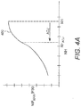
- Fig. 4A shows a graphical representation of the fuel supply limit model 400 with the vertical axis representative of the maximum fuel level as a function of pressure of the air exhausted from the high pressure compressor, WF max /P30, and the horizontal axis representative of rotational shaft speed NH.
- the speed NH is obtained from speed sensors 124, which may suitably be disposed just in front of the HP shaft thrust bearing, not shown, at the front of the high pressure compressor 14. However, in other applications, the speed sensor 124 may be placed in an accessory gearbox, not shown, but which would be known to those of ordinary skill in the art, where the speed sensor 124 is operably coupled to measure speed from a driven component, for example, a permanent magnet generator (PMG). In accordance with an embodiment of the present invention, however, this known model 400 may be adjusted upon detection of a possible shaft break.
- PMG permanent magnet generator
- a shaft break is typically characterized by a sudden decrease in rotational speed of the compressor and released hardware (due to the disconnection of the shaft from the drive/turbine).
- the controller 100 effectively adjusts the NH value used to determine WF max in the model 400 depicted in Fig. 4A .
- the controller 100 preferably stores information representative of the model 400 in memory 101.
- Fig. 4B shows an exemplary set of operations that may be carried out by the controller 100 to implement this operation.
- the controller 100 obtains the rotational speed value NH from the sensor(s) shown in Figure 3 .
- the controller 100 differentiates the value NH to obtain the value ⁇ NH. The differentiation may be carried out digitally or via analog processes.
- the controller identifies any adjustment value ADJ that corresponds to the value ⁇ NH.
- the graph of Fig. 4C may be employed, which shows ADJ as a function of reduction of ⁇ NH. Information representative of the relationship depicted in Fig. 4C may also be stored in memory 101.
- the controller 100 employs the ADJ value to modify the perceived NH speed and thereby reduces the maximum fuel limit function 400 of Fig. 4A .
- the controller 100 may suitably subtract the adjustment value ADJ from the actual speed value NH to obtain an adjusted speed value NH ADJ , and identify the value WF max that corresponds with the value NH ADJ using the function 400 of Fig. 4A . As shown in Fig. 4A , this adjustment results in a lower WF max than would normally occur at the speed NH.
- the controller 100 thereafter in step 410 controls the fuel supplied to the fuel valve actuators 120 using the maximum fuel limit value WF max identified in step 408.
- Fig. 4B merely illustrates the generalized operations carried out by the controller 100 to perform the preliminary shaft failure detection and remediation, and is not intended to define the detailed software (or hardware) operations of the controller 100.
- the operations of Fig. 4B are repeated in an ongoing manner, which allows for possible recovery if the speed value NH recovers. If a shaft failure is subsequently detected by other, conventional means, then the controller 100 may completely cut off the fuel supply.
- the controller 100 in this embodiment first obtains a first value (e.g. NH ) representative of a rotational speed of one or more of the shafts of a turbine.
- the controller 100 differentiates the first value to obtain the rate of change.
- the controller 100 then adjusts the model of Fig. 4A based on the differentiated first value.
- the controller 100 thereafter carries out its normal control mechanisms, such as controlling fuel supply based on the adjusted version of NH based on the model in Fig. 4A .
- the controller 100 may suitably move the speed value back (or curve of Fig. 4A forward) by a value corresponding to the differentiated first value.
- the curve 400 will effectively move to the right by a value corresponding to the deceleration rate. This results in the fuel supply limit being even lower (at any particular rotational speed NH ) than would result from normal operation at that rotational speed NH.
- another known control feature may be manipulated to provide a preliminary detection and response to a possible shaft break.
- the controller 100 in this embodiment employs a known control scheme that limits the amount of fuel that can be supplied to an engine upon restart.
- a fast windmill restart can cause issues due to residual heat in components within the engine.
- it is known to control the fuel supply such that during conditions indicative of a fast windmill restart, the amount of fuel is limited to the engine.
- the details of an exemplary embodiment of this control scheme are shown and discussed in U.S. Patent 5,628,185 .
- the start bias control scheme is modified to provide even further fuel feed reduction when excessively high temperatures, those typically not associated with fast windmill restart, are detected. Such excessively high temperatures can be indicative of a shaft failure. Accordingly, the modified start bias control scheme provides early detection and mitigation of a possible shaft failure without completely shutting off the fuel.
- Fig. 5 a modified version of the start bias control scheme described in U.S. Patent 5,628,185 , which is incorporated by reference, is shown.
- the control scheme of Fig. 5 which is carried out by the controller 100, provides start bias (fuel modifier) control similar to that of the prior art, but also provides early detection and response to a possible shaft failure.
- the controller 100 reduces the fuel to a degree which will avoid overheating issues as the engine restarts and begins to push cooler fresh air through the heated components. If, however, conditions indicate that a shaft 20, 21, 22 may have failed, then the controller 100 reduces the fuel to a greater degree to reduce the probability of disc burst or high energy blade release. Nevertheless, the fuel is not completely cut off and the engine 10 may recover if it is ultimately determined that the shaft has not failed.
- This relationship is depicted as 534 in Fig. 5 .
- This processing of the input signals T20, P30 and P20 provides an output signal 535 of T30 synth / T20. That output 535 is then processed by the multiplication unit 536 which also has T20 as an input signal to provide an output signal 537 which is representative of T30 synth .
- the T30 synth output signal 537 is then directed to a summing and subtraction unit 538 which is adapted to provide an output signal 539 which equals the difference between two input signals.
- the second input signal to the unit 538 is the output signal T30 of the thermocouples 23, which is representative of the actual temperature of the air exhausted from the downstream end of the high pressure compressor 14.
- the output signal from the thermocouple 23 is designated T30 meas .
- the output signal 539 of the unit 538 which is designated ⁇ T30 equals T30 meas -T30 synth .
- the signal ⁇ T30 is therefore representative of the difference between the actual temperature of the air exhausted from the downstream end of the high pressure compressor 14 and the theoretical temperature of the air which would be expected under normal engine running conditions. As will be discussed below, within a first range of values, this differential could be due to temperature increase resulting from a compressor stall. However, within a second range of values, a much greater difference could be due to a temperature increase and other parameter changes that are indicative of a shaft failure.
- the ⁇ T30 signal 539 is employed to determine a fuel derate value, WF / P30 derate , as depicted in the relationship at 540.
- WF is representative of the rate of flow of fuel to the engine 10 and P30 is, as previously stated, representative of the pressure of the air exhausted from the high pressure compressor 14.
- the derate value relationship depicted at 540 is selected such that if ⁇ T30 does not exceed a minimum threshold, then there is no WF / P30 derate output. However, if ⁇ T30 exceeds the minimum threshold, then there is a WF / P30 derate output signal 541 which increases with ⁇ T30 up to an intermediate maximum or constant derate value.
- the minimum to maximum threshold range represents the probable range relating to a restart after an engine stall (called a quick windmill relight) or other low idle condition. In accordance with the present invention, however, if ⁇ T30 further exceeds the maximum threshold, then the WF/P30 derate signal increases even further. The choice of this threshold for the start of the second range of increase may be altered, but in general is intended to exceed any change in compressor temperature typically associated with quick windmill restart.
- the WF / P30 derate signal 541 is then directed into a multiplication unit 542 which multiplies the signal 541 by a derate factor signal 543.
- the derate factor signal 543 is derived from a relationship depicted at 544 between derate factor and NH / ⁇ 20 which is an expression representative of the speed of rotation of the engine 10. Essentially, if the rotational speed of the engine is less than 50% of what it should be under cruise conditions, then the derate factor is 1. Consequently, under these circumstances the output signal 545 of the multiplication device is the same as the input signal 541 which is WF / P30 derate However, as the engine speed increases to 60% of cruise, the derate factor 543 progressively decreases to zero. Consequently, if the speed of the engine 10 is greater than 60% of cruise speed (where 60% NH is representative of the minimum idle speed for the representative application), the output 545 from the multiplication unit 542 is set to zero.
- the output 545 of the multiplication unit 542 is directed into a summing and subtraction unit 546 which subtracts the output 545 from 1.0 to provide a final output signal 547.
- the final output signal 547 is then directed to the main fuel control function 548 of the controller 100.
- the control function 548 then adjusts the normal fuel control signal provided to the FV actuators 120 of Fig. 3 by multiplying that signal by the final output signal 547.
- the various "units" 536, 538, 542 and 546 may be simply mathematical operations carried out by a programmed processor within the controller 100, or may be carried out by analog circuitry.
- information representative of the relationships 534, 540, and 544 may be stored in any suitable format (e.g. piece-wise linear equation, mathematical function, or look-up table) in memory 101 associated with the controller 100, shown in Fig 3 .
- the relationships may also be implemented purely in software steps.
- the derate factor signal 543 will be zero and so, consequently will be the multiplication device output signal 545. This results in the final output signal 547 being 1.0 and therefore having no effect upon the operation of the main fuel control function 548.
- the final output signal 547 is now less than 1.0, it has an effect upon the operation of the main fuel control function 548 so that the rate at which fuel is supplied to the engine 10 is reduced by that proportion.
- the amount by which the rate of fuel supply is reduced is arranged to be sufficient to change the stall characteristics of the high pressure compressor 14. The stall characteristics are changed to such an extent that during the engine 10 restarting procedure, the high pressure compressor 14 does not stall, thereby in turn permitting effective engine 10 restarting.
- the engine rotational speed increases, thereby in turn increasing the value of NH / ⁇ 20 so that the derate factor signal 543 decreases to zero.
- This in turn leads to the output signal 545 from the multiplication device 542 also decreasing to zero, thereby causing the final output signal 547 to return to its original value of 1.0.
- the main fuel control unit 548 reverts to supplying fuel to the engine 10 at a normal rate, thereby permitting normal engine operation.
- One advantageous aspect of the control scheme of Fig. 5 is the alteration of the fuel rate to ⁇ T30 relationship 540 such that it has two distinct zones - one associated with fast windmill restart and the other associated with possible shaft failure.
- the derate value increases at a first average rate as a function of the differential temperature value up until a point, at which point the derate value stays constant (or at least increases at lesser rate) for a range of differential temperature values.
- fast windmill restart can be hindered.
- the WF/P30 d erate remains at the same value throughout the rest of the range of temperatures associated with fast windmill restart.
- the derate value increases again at a more aggressive average rate with respect to the differential temperature value.
- the more aggressive rate may be similar to the first average rate.
- the Z-shaped curve of the relationship 540 allows for two-different control objectives to be obtained within the same control topology.
- ⁇ T30 would increase through the range of 60° K to 180° K into the range well beyond that associated with windmill restart. As the ⁇ T30 exceeds 300° K (or other suitable range above that associated with fast windmill restart), the WF / P30 derate signal 545 begins increasing again to even higher values, beyond the intermediate constant FWRM, further reducing the fuel rate.
- the controller 100 otherwise operates in the manner described above.
- the controller 100 when shaft failure is confirmed by other means, the controller 100 causes the fuel to be completely cut-off from the engine 10. If, however, a shaft failure has not occurred, and the ⁇ T30 is due other factors, then the engine 10 may gracefully recover without shutting off the fuel completely.
- the shaft rotational speed sensor signal may not be available.
- shaft failure and other events can involve failure of the shaft rotational speed sensor 124. (See Fig. 3 ). Because rotational speed sensors can fail, it is known to employ logic in the controller 100 that estimates rotational speed NH based on other engine operating parameters. The controller 100 then uses the estimated speed for its control operations.
- Fig. 6 shows a model 600 of estimated rotational speed as a function of the sensed pressure value P30, which is obtained from the sensor 33 located near the inlet of the combustor 15.
- the estimated speed NH est expressed as a percentage of shaft design speed, is shown as a function of the ratio of P30 to a value ⁇ P20.
- the value ⁇ P20 is a normalizing parameter based on the Buckingham Pie theorem/principle, which in this embodiment is equal to P20 /14.696.
- the solid line 602 represents the true estimated correlation between the pressures sensor values P30 / ⁇ P20 and the corrected rotational speed of the shaft (e.g. shaft 20, 21 or 22), NH / ⁇ 20.
- the model 600 has a first portion 604 that consists of a part of the solid line 602, thereby representing the proper correlation between the pressure sensor values P30 / ⁇ P20 and rotational speed NH of the shaft.
- the model 600 has a second portion 606, represented by the dashed line, that differs from the actual correlation 602.
- the estimated rotational speed NH est of the first model in the second portion is less than a rotational speed of the shaft for the corresponding pressure sensor value
- the controller 100 operates with an estimated speed value NH est that is lower than the actual speed that would be expected for that pressure value.
- the controller 100 can employ control mechanism such as those shown in Figs. 4A , 4B , 4C or 5 , using the artificially lowered speed value NHest.
- the artificially reduced estimated speed NH est moves backward in the model 400 to a lower maximum fuel rate WF max .
- the model 600 is adjusted in very low pressure value areas (e.g. between P30 1 and P30 2 ) that are more likely to be associated with shaft failure. This again limits the fuel in the event of a possible shaft break, thereby limiting the risk of disc burst or blade release.
- the controller 100 receives a speed sensor fault signal. As a consequence of receiving the fault signal, the controller 100 employs an estimated speed signal NH est for various control operations. To this end, the controller 100 uses the adjusted model 600 of Fig. 6 (with the segment 606) in its various control schemes.
- the controller 100 performs the maximum fuel limit control such as shown in Fig. 4B , or the operations of Fig. 5 , using the estimated value NH est .
- the pressure P30 will rapidly decrease into the zone between P30 1 and P30 2 .
- the controller 100 will use an estimated speed NH est that is below what would normally be expected for the pressure level value.
- the controller 100 executing the operations of Fig. 5 will use an NH / ⁇ 20 value with the lower NH est value in determining the derate factor 543. This results in the derate factor more rapidly increasing to 1.0.
- the controller 100 can resume operating the engine 10 normally without the extreme precautionary measure of shutting the engine down completely, as would traditionally occur when a shaft break is detected.
Landscapes
- Engineering & Computer Science (AREA)
- Chemical & Material Sciences (AREA)
- Combustion & Propulsion (AREA)
- Mechanical Engineering (AREA)
- General Engineering & Computer Science (AREA)
- Supercharger (AREA)
- Control Of Positive-Displacement Air Blowers (AREA)
Claims (14)
- Verfahren zum Ausführen einer vorläufigen Schutzmaßnahme vor der Erkennung eines Wellenfehlers in einem Gasturbinentriebwerk (10), wobei das Verfahren Folgendes umfasst:a) Steuern der Kraftstoffversorgung eines Gasturbinentriebwerks (10) mindestens teilweise unter Verwendung einer Kraftstoffversorgungsgrenze, die als eine erste Funktion von einer Drehzahl, NH, NI, NL, einer Welle (20, 21, 22) eines Gasturbinentriebwerks (10) bestimmt wurde;b) Abrufen (402) eines ersten Wertes, der für eine Drehzahl, NH, NI, NL, der Welle (20, 21, 22) repräsentativ ist;c) Differenzieren (404) des ersten Wertes innerhalb einer Verarbeitungseinheit;d) Einsetzen (408) der Verarbeitungseinheit, um eine angepasste Kraftstoffversorgungsgrenze als eine angepasste Funktion des ersten Wertes zu bestimmen, wobei die angepasste Funktion auf der ersten Funktion und auf dem differenzierten ersten Wert basiert; unde) Steuern (410) der Kraftstoffversorgung des Gasturbinentriebwerks (10) mindestens teilweise unter Verwendung der angepassten Kraftstoffversorgungsgrenze.
- Verfahren nach Anspruch 1, wobei Schritt d) ferner Folgendes umfasst:d1) Bestimmen (406) eines Anpassungswertes auf der Grundlage des differenzierten ersten Wertes;d2) Bestimmen (408) der angepassten Kraftstoffversorgungsgrenze als eine Funktion einer Kombination von dem Anpassungswert und dem ersten Wert.
- Verfahren nach Anspruch 1, wobei Schritt b) ferner ein Abrufen des ersten Wertes auf der Grundlage eines Drehzahlsensorwertes (106) umfasst.
- Verfahren nach Anspruch 1, wobei Schritt b) ferner Folgendes umfasst:b1) Abrufen mindestens eines Drucksensorwertes, P20, P30, der repräsentativ für eine Druckdifferenz über mindestens einen Verdichter (13, 14) ist;b2) Anwenden eines ersten Modells (600) zum Bestimmen der Drehzahl, NH, NI, NL, auf der Grundlage des mindestens einen Drucksensorwertes, P20, P30, wobei das erste Modell (600) einen ersten Abschnitt (604) aufweist, der eine Korrelation zwischen einem Drucksensorwert, P20, P30, und einer Drehzahl, NH, NI, NL, repräsentiert, und einen zweiten Abschnitt (606), der sich von der Korrelation unterscheidet.
- Verfahren nach Anspruch 4, wobei das erste Modell (600) ferner so konfiguriert ist, dass die Drehzahl, NH, NI, NL, des ersten Modells in dem zweiten Abschnitt kleiner als eine Drehzahl, NH, NI, NL, der Welle (20, 21, 22) ist, die mit dem entsprechenden Drucksensorwert, P20, P30, korreliert.
- Verfahren zum Ausführen einer vorläufigen Schutzmaßnahme vor der Erkennung eines Wellenfehlers in einem Gasturbinentriebwerk (10), wobei das Verfahren Folgendes umfasst:a) Abrufen mindestens eines Drucksensorwertes, P20, P30, der repräsentativ für eine Druckdifferenz über mindestens einen Verdichter (13, 14) eines Gasturbinentriebwerks (10) ist;b) Anwenden eines ersten Modells (600) zum Bestimmen einer geschätzten Drehzahl einer Welle (20, 21, 22) des Gasturbinentriebwerks (10) auf der Grundlage mindestens eines Drucksensorwertes (102), wobei das erste Modell einen ersten Abschnitt (604) aufweist, der eine Korrelation zwischen einem Drucksensorwert, P20, P30, und einer Drehzahl, NH, NI, NL, der Welle (20, 21, 22) repräsentiert, und einen zweiten Abschnitt (606), der sich von der Korrelation unterscheidet, sodass die geschätzte Drehzahl des ersten Modells in dem zweiten Abschnitt kleiner als eine Drehzahl der Welle für den entsprechenden Drucksensorwert ist; undc) Bestimmen einer Kraftstoffversorgungsgrenze (400) als eine Funktion der geschätzten Drehzahl, NH, NI, NL; undd) Steuern der Kraftstoffversorgung zu dem Gasturbinentriebwerk (10), mindestens teilweise unter Anwendung der Kraftstoffversorgungsgrenze.
- Verfahren nach Anspruch 6, ferner umfassend, vor Schritt a)i) Bestimmen einer ersten Kraftstoffversorgungsgrenze (400) als eine Funktion eines Wertes (106) von einem Drehzahlsensor (124);ii) Steuern der Kraftstoffversorgung des Gasturbinentriebwerks (10) mindestens teilweise unter Anwendung der Kraftstoffversorgungsgrenze (400); undiii) in Reaktion auf das Empfangen eines Signals, das bezeichnend für einen Fehler des Drehzahlsensors (124) ist, Ausführen der Schritte a, b, c und d.
- Verfahren nach Anspruch 6, ferner umfassend ein Speichern von Informationen, die das erste Modell (600) in einer Speichervorrichtung (101) definieren.
- Verfahren zum Ausführen einer vorläufigen Schutzmaßnahme vor der Erkennung eines Wellenfehlers in einem Gasturbinentriebwerk (10), wobei das Verfahren Folgendes umfasst:a) Steuern der Kraftstoffversorgung eines Gasturbinentriebwerks (10) auf der Grundlage gemessener Werte (102, 104, 106, 108), um einen Kraftstoffversorgungswert zu generieren;b) Abrufen eines Differenztemperaturwertes (539), der repräsentativ für eine Differenz zwischen einer erwarteten Temperatur an einem Ausgang eines Verdichters (14) eines Gasturbinentriebwerks (10) und einer gemessenen Temperatur an dem Ausgang ist;c) Generieren eines Reduktionswertes (541), wenn der Differenztemperaturwert (539) eine erste Schwelle überschreitet, wobei der Reduktionswert (541) als eine Funktion (540) des Differenztemperaturwertes (539) bestimmt wird, wobei sich der Reduktionswert in einer ersten durchschnittlichen Rate als eine Funktion des Differenztemperaturwertes erhöht, wenn der Differenztemperaturwert kleiner als eine zweite Schwelle ist, sich der Reduktionswert in einer zweiten durchschnittlichen Rate, die kleiner als eine erste durchschnittliche Rate ist, erhöht, wenn der Differenztemperaturwert größer als die zweite Schwelle und kleiner als eine dritte Schwelle ist, und sich der Reduktionswert in einer dritten durchschnittlichen Rate, die größer als eine zweite durchschnittliche Rate ist, erhöht, wenn der Differenztemperaturwert größer als die dritte Schwelle ist;d) Verwenden einer Steuerung (100, 548) zur Reduzierung des Kraftstoffversorgungswertes mindestens teilweise auf der Grundlage des Reduktionswertes (541).
- Verfahren nach Anspruch 9, wobei die dritte Schwelle einem Schwellendifferenztemperaturwert entspricht, der Differenztemperaturwerte überschreitet, die einem Neustart des Gasturbinentriebwerks nach einem Herunterfahren oder Flammabriss zugeordnet sind.
- Verfahren nach Anspruch 9, wobei die zweite Durchschnittsrate im Wesentlichen null ist.
- Verfahren nach Anspruch 9, wobei Schritt d) ferner ein Verwenden einer Steuerung (100, 548) zum Reduzieren des Kraftstoffversorgungswertes umfasst, das ferner auf einem Wert (543) basiert, der repräsentativ für eine Drehzahl, NH, NI, NL, einer Welle (20, 21, 22) des Gasturbinentriebwerks (10) ist.
- Verfahren nach Anspruch 12, wobei Schritt d) ferner das Abrufen des Wertes, der repräsentativ für die Drehzahl, NH, NI, NL, ist, von einem Drehzahlsensor (124) umfasst.
- Verfahren nach Anspruch 12, wobei Schritt d) ferner ein Beschaffen des Wertes umfasst, der repräsentativ für die Drehzahl, NH, NI, NL, ist:Beschaffen mindestens eines Drucksensorwertes, der repräsentativ für eine Druckdifferenz über mindestens einen Verdichter (13, 14) ist;Anwenden eines ersten Modells (600) zum Bestimmen der Drehzahl, NH, NI, NL, auf der Grundlage des mindestens einen Drucksensorwertes (102), wobei das erste Modell einen ersten Abschnitt (604) aufweist, der eine Korrelation zwischen einem Drucksensorwert und einer Drehzahl repräsentiert, und einen zweiten Abschnitt (606), der sich von der Korrelation unterscheidet.
Applications Claiming Priority (1)
| Application Number | Priority Date | Filing Date | Title |
|---|---|---|---|
| US201562194582P | 2015-07-20 | 2015-07-20 |
Publications (2)
| Publication Number | Publication Date |
|---|---|
| EP3121389A1 EP3121389A1 (de) | 2017-01-25 |
| EP3121389B1 true EP3121389B1 (de) | 2019-11-20 |
Family
ID=56418359
Family Applications (1)
| Application Number | Title | Priority Date | Filing Date |
|---|---|---|---|
| EP16172890.2A Active EP3121389B1 (de) | 2015-07-20 | 2016-06-03 | Gasturbinesteuerungsverfahren mit korrekturmassnahme im falle einer erkennung eines potenziellen wellenfehlers |
Country Status (2)
| Country | Link |
|---|---|
| US (1) | US9982607B2 (de) |
| EP (1) | EP3121389B1 (de) |
Families Citing this family (16)
| Publication number | Priority date | Publication date | Assignee | Title |
|---|---|---|---|---|
| US9909508B2 (en) * | 2014-06-26 | 2018-03-06 | General Electric Company | Automatic combustion system characterization |
| US10371002B2 (en) * | 2016-06-14 | 2019-08-06 | General Electric Company | Control system for a gas turbine engine |
| US10865646B2 (en) | 2017-05-04 | 2020-12-15 | Rolls-Royce Corporation | Turbine assembly with auxiliary wheel |
| US10968744B2 (en) | 2017-05-04 | 2021-04-06 | Rolls-Royce Corporation | Turbine rotor assembly having a retaining collar for a bayonet mount |
| US10774678B2 (en) | 2017-05-04 | 2020-09-15 | Rolls-Royce Corporation | Turbine assembly with auxiliary wheel |
| US11280683B2 (en) | 2017-05-31 | 2022-03-22 | Pratt & Whitney Canada Corp. | Method and system for detecting high turbine temperature operations |
| US11293353B2 (en) | 2017-05-31 | 2022-04-05 | Raytheon Technologies Corporation | Transient control to extend part life in gas turbine engine |
| GB201908494D0 (en) | 2019-06-13 | 2019-07-31 | Rolls Royce Plc | Computer-implemented methods for training a machine learning algorithm |
| GB201908496D0 (en) | 2019-06-13 | 2019-07-31 | Rolls Royce Plc | Computer-implemented methods for determining compressor operability |
| GB201908497D0 (en) * | 2019-06-13 | 2019-07-31 | Rolls Royce Plc | Computer-implemented methods for controlling a gas turbine engine |
| US11333035B2 (en) * | 2019-07-24 | 2022-05-17 | Pratt & Whitney Canada Corp. | Shaft shear detection in a gas turbine engine |
| EP3789603B1 (de) * | 2019-08-12 | 2025-01-08 | RTX Corporation | Elektrische hilfskraftunterstützung für motorneustart im flug |
| CN110657031B (zh) * | 2019-09-30 | 2020-10-23 | 山东超越数控电子股份有限公司 | 飞机发动机喘振识别方法 |
| US11658594B2 (en) | 2019-10-21 | 2023-05-23 | General Electric Company | System and method to detect low speed in a gas turbine generator |
| IT202000028520A1 (it) | 2020-11-26 | 2022-05-26 | Ge Avio Srl | Sistema e metodo per la mitigazione di velocita' eccessiva di rotore |
| CN113294246B (zh) * | 2021-06-30 | 2022-11-04 | 中国航发动力股份有限公司 | 一种燃气轮机可转导叶控制方法 |
Family Cites Families (13)
| Publication number | Priority date | Publication date | Assignee | Title |
|---|---|---|---|---|
| GB9410760D0 (en) | 1994-05-27 | 1994-07-27 | Rolls Royce Plc | Gas turbine engine fuel control system |
| US6176074B1 (en) | 1998-06-05 | 2001-01-23 | Pratt & Whitney Canada Corp. | Shaft decouple logic for gas turbine |
| US6915639B1 (en) | 2000-10-13 | 2005-07-12 | General Electric Company | Method and apparatus for gas turbine over-speed protection |
| US6619027B1 (en) | 2000-10-13 | 2003-09-16 | General Electric Company | Gas turbine having rotor overspeed and overboost protection |
| US7043896B2 (en) | 2003-11-21 | 2006-05-16 | Pratt & Whitney Canada Corp. | Method and apparatus for controlling fuel flow to an engine |
| JP4434815B2 (ja) | 2004-03-31 | 2010-03-17 | 本田技研工業株式会社 | ガスタービン・エンジンの制御装置 |
| FR2907839B1 (fr) | 2006-10-25 | 2011-06-17 | Snecma | Methode pour reduire la vitesse en cas de rupture d'arbre de turbine de moteur a turbine a gaz |
| US8224552B2 (en) | 2008-07-10 | 2012-07-17 | General Electric Company | Methods and systems to facilitate over-speed protection |
| US8321119B2 (en) | 2008-07-10 | 2012-11-27 | General Electric Company | Methods and systems to facilitate over-speed protection |
| US8381510B2 (en) | 2009-04-30 | 2013-02-26 | General Electric Company | Method and systems for controlling engine thrust using variable trim |
| JP5356949B2 (ja) | 2009-08-24 | 2013-12-04 | 本田技研工業株式会社 | ガスタービン・エンジンの過回転防止装置 |
| JP2011043136A (ja) | 2009-08-24 | 2011-03-03 | Honda Motor Co Ltd | ガスタービン・エンジンの始動時燃料制御装置 |
| GB201121639D0 (en) * | 2011-12-16 | 2012-01-25 | Rolls Royce Plc | Shaft break detection |
-
2016
- 2016-05-09 US US15/149,256 patent/US9982607B2/en active Active
- 2016-06-03 EP EP16172890.2A patent/EP3121389B1/de active Active
Non-Patent Citations (1)
| Title |
|---|
| None * |
Also Published As
| Publication number | Publication date |
|---|---|
| US9982607B2 (en) | 2018-05-29 |
| US20170022907A1 (en) | 2017-01-26 |
| EP3121389A1 (de) | 2017-01-25 |
Similar Documents
| Publication | Publication Date | Title |
|---|---|---|
| EP3121389B1 (de) | Gasturbinesteuerungsverfahren mit korrekturmassnahme im falle einer erkennung eines potenziellen wellenfehlers | |
| US4117668A (en) | Stall detector for gas turbine engine | |
| EP3284932B1 (de) | Kraftstoffpumpenzustandüberwachung | |
| EP3464834B1 (de) | Turbinenmotor und betriebsverfahren | |
| EP1444428B1 (de) | Verfahren und vorrichtung zur vermeidung des pumpens in einer gasturbine | |
| US7584618B2 (en) | Controlling air flow to a turbine shroud for thermal control | |
| US10371002B2 (en) | Control system for a gas turbine engine | |
| EP3392485B1 (de) | Kraftstoffregelungssystem | |
| EP1069296B1 (de) | Verfahren zur Anzeige der Ausgangsleistung einer Turbine | |
| EP4528110A1 (de) | Verfahren zur erkennung und meldung des strömungsabrisses eines gasturbinentriebwerks | |
| US9447735B2 (en) | Method of controlling a turbomachine | |
| CN114945734B (zh) | 用于控制高压涡轮的间隙以降低egt超调影响的控制方法和单元 | |
| US10619573B2 (en) | Method of starting a gas turbine engine | |
| CA2959659A1 (en) | Controlling a compressor of a gas turbine engine | |
| EP3409926B1 (de) | Verfahren und system zur detektion eines hochtemperaturzustands einer gasturbine | |
| US10150569B2 (en) | Method of stopping a rotorcraft engine in overspeed, and a system and a rotorcraft associated therewith | |
| US10309249B2 (en) | Control apparatus for a gas-turbine aeroengine | |
| CA2929833C (en) | Shaft failure detection using passive control methods | |
| EP2458179B1 (de) | Verfahren zur Überwachung einer elektronischen Motorsteuerung zur Erkennung der Verschmutzung eines Kraftstofffilters | |
| US20050262825A1 (en) | Apparatus and a method for regulating the flow rate of fuel to a turboshaft engine in acceleration or in deceleration | |
| US9938906B2 (en) | Combustion stability logic during off-load transients | |
| EP4368500A1 (de) | Systeme und verfahren zur steuerung des fluiddrucks einer propellersteuereinheit | |
| EP4148256A1 (de) | Ausgangsleistungsverwaltung für motoren | |
| EP4553310A1 (de) | Referenzbeschleunigungssteuerungsarchitektur für gemischte n-punkt- und verhältniseinheit für gasturbinenmotor |
Legal Events
| Date | Code | Title | Description |
|---|---|---|---|
| PUAI | Public reference made under article 153(3) epc to a published international application that has entered the european phase |
Free format text: ORIGINAL CODE: 0009012 |
|
| STAA | Information on the status of an ep patent application or granted ep patent |
Free format text: STATUS: THE APPLICATION HAS BEEN PUBLISHED |
|
| AK | Designated contracting states |
Kind code of ref document: A1 Designated state(s): AL AT BE BG CH CY CZ DE DK EE ES FI FR GB GR HR HU IE IS IT LI LT LU LV MC MK MT NL NO PL PT RO RS SE SI SK SM TR |
|
| AX | Request for extension of the european patent |
Extension state: BA ME |
|
| STAA | Information on the status of an ep patent application or granted ep patent |
Free format text: STATUS: REQUEST FOR EXAMINATION WAS MADE |
|
| 17P | Request for examination filed |
Effective date: 20170725 |
|
| RBV | Designated contracting states (corrected) |
Designated state(s): AL AT BE BG CH CY CZ DE DK EE ES FI FR GB GR HR HU IE IS IT LI LT LU LV MC MK MT NL NO PL PT RO RS SE SI SK SM TR |
|
| GRAP | Despatch of communication of intention to grant a patent |
Free format text: ORIGINAL CODE: EPIDOSNIGR1 |
|
| STAA | Information on the status of an ep patent application or granted ep patent |
Free format text: STATUS: GRANT OF PATENT IS INTENDED |
|
| INTG | Intention to grant announced |
Effective date: 20190614 |
|
| GRAS | Grant fee paid |
Free format text: ORIGINAL CODE: EPIDOSNIGR3 |
|
| GRAA | (expected) grant |
Free format text: ORIGINAL CODE: 0009210 |
|
| STAA | Information on the status of an ep patent application or granted ep patent |
Free format text: STATUS: THE PATENT HAS BEEN GRANTED |
|
| AK | Designated contracting states |
Kind code of ref document: B1 Designated state(s): AL AT BE BG CH CY CZ DE DK EE ES FI FR GB GR HR HU IE IS IT LI LT LU LV MC MK MT NL NO PL PT RO RS SE SI SK SM TR |
|
| REG | Reference to a national code |
Ref country code: GB Ref legal event code: FG4D |
|
| REG | Reference to a national code |
Ref country code: CH Ref legal event code: EP |
|
| REG | Reference to a national code |
Ref country code: IE Ref legal event code: FG4D |
|
| REG | Reference to a national code |
Ref country code: DE Ref legal event code: R096 Ref document number: 602016024536 Country of ref document: DE |
|
| REG | Reference to a national code |
Ref country code: AT Ref legal event code: REF Ref document number: 1204435 Country of ref document: AT Kind code of ref document: T Effective date: 20191215 |
|
| REG | Reference to a national code |
Ref country code: NL Ref legal event code: MP Effective date: 20191120 |
|
| REG | Reference to a national code |
Ref country code: LT Ref legal event code: MG4D |
|
| PG25 | Lapsed in a contracting state [announced via postgrant information from national office to epo] |
Ref country code: LV Free format text: LAPSE BECAUSE OF FAILURE TO SUBMIT A TRANSLATION OF THE DESCRIPTION OR TO PAY THE FEE WITHIN THE PRESCRIBED TIME-LIMIT Effective date: 20191120 Ref country code: SE Free format text: LAPSE BECAUSE OF FAILURE TO SUBMIT A TRANSLATION OF THE DESCRIPTION OR TO PAY THE FEE WITHIN THE PRESCRIBED TIME-LIMIT Effective date: 20191120 Ref country code: LT Free format text: LAPSE BECAUSE OF FAILURE TO SUBMIT A TRANSLATION OF THE DESCRIPTION OR TO PAY THE FEE WITHIN THE PRESCRIBED TIME-LIMIT Effective date: 20191120 Ref country code: NL Free format text: LAPSE BECAUSE OF FAILURE TO SUBMIT A TRANSLATION OF THE DESCRIPTION OR TO PAY THE FEE WITHIN THE PRESCRIBED TIME-LIMIT Effective date: 20191120 Ref country code: GR Free format text: LAPSE BECAUSE OF FAILURE TO SUBMIT A TRANSLATION OF THE DESCRIPTION OR TO PAY THE FEE WITHIN THE PRESCRIBED TIME-LIMIT Effective date: 20200221 Ref country code: NO Free format text: LAPSE BECAUSE OF FAILURE TO SUBMIT A TRANSLATION OF THE DESCRIPTION OR TO PAY THE FEE WITHIN THE PRESCRIBED TIME-LIMIT Effective date: 20200220 Ref country code: BG Free format text: LAPSE BECAUSE OF FAILURE TO SUBMIT A TRANSLATION OF THE DESCRIPTION OR TO PAY THE FEE WITHIN THE PRESCRIBED TIME-LIMIT Effective date: 20200220 Ref country code: FI Free format text: LAPSE BECAUSE OF FAILURE TO SUBMIT A TRANSLATION OF THE DESCRIPTION OR TO PAY THE FEE WITHIN THE PRESCRIBED TIME-LIMIT Effective date: 20191120 |
|
| PG25 | Lapsed in a contracting state [announced via postgrant information from national office to epo] |
Ref country code: HR Free format text: LAPSE BECAUSE OF FAILURE TO SUBMIT A TRANSLATION OF THE DESCRIPTION OR TO PAY THE FEE WITHIN THE PRESCRIBED TIME-LIMIT Effective date: 20191120 Ref country code: RS Free format text: LAPSE BECAUSE OF FAILURE TO SUBMIT A TRANSLATION OF THE DESCRIPTION OR TO PAY THE FEE WITHIN THE PRESCRIBED TIME-LIMIT Effective date: 20191120 Ref country code: IS Free format text: LAPSE BECAUSE OF FAILURE TO SUBMIT A TRANSLATION OF THE DESCRIPTION OR TO PAY THE FEE WITHIN THE PRESCRIBED TIME-LIMIT Effective date: 20200320 |
|
| PG25 | Lapsed in a contracting state [announced via postgrant information from national office to epo] |
Ref country code: AL Free format text: LAPSE BECAUSE OF FAILURE TO SUBMIT A TRANSLATION OF THE DESCRIPTION OR TO PAY THE FEE WITHIN THE PRESCRIBED TIME-LIMIT Effective date: 20191120 |
|
| PG25 | Lapsed in a contracting state [announced via postgrant information from national office to epo] |
Ref country code: CZ Free format text: LAPSE BECAUSE OF FAILURE TO SUBMIT A TRANSLATION OF THE DESCRIPTION OR TO PAY THE FEE WITHIN THE PRESCRIBED TIME-LIMIT Effective date: 20191120 Ref country code: RO Free format text: LAPSE BECAUSE OF FAILURE TO SUBMIT A TRANSLATION OF THE DESCRIPTION OR TO PAY THE FEE WITHIN THE PRESCRIBED TIME-LIMIT Effective date: 20191120 Ref country code: DK Free format text: LAPSE BECAUSE OF FAILURE TO SUBMIT A TRANSLATION OF THE DESCRIPTION OR TO PAY THE FEE WITHIN THE PRESCRIBED TIME-LIMIT Effective date: 20191120 Ref country code: PT Free format text: LAPSE BECAUSE OF FAILURE TO SUBMIT A TRANSLATION OF THE DESCRIPTION OR TO PAY THE FEE WITHIN THE PRESCRIBED TIME-LIMIT Effective date: 20200412 Ref country code: EE Free format text: LAPSE BECAUSE OF FAILURE TO SUBMIT A TRANSLATION OF THE DESCRIPTION OR TO PAY THE FEE WITHIN THE PRESCRIBED TIME-LIMIT Effective date: 20191120 Ref country code: ES Free format text: LAPSE BECAUSE OF FAILURE TO SUBMIT A TRANSLATION OF THE DESCRIPTION OR TO PAY THE FEE WITHIN THE PRESCRIBED TIME-LIMIT Effective date: 20191120 |
|
| REG | Reference to a national code |
Ref country code: AT Ref legal event code: MK05 Ref document number: 1204435 Country of ref document: AT Kind code of ref document: T Effective date: 20191120 |
|
| REG | Reference to a national code |
Ref country code: DE Ref legal event code: R097 Ref document number: 602016024536 Country of ref document: DE |
|
| PG25 | Lapsed in a contracting state [announced via postgrant information from national office to epo] |
Ref country code: SK Free format text: LAPSE BECAUSE OF FAILURE TO SUBMIT A TRANSLATION OF THE DESCRIPTION OR TO PAY THE FEE WITHIN THE PRESCRIBED TIME-LIMIT Effective date: 20191120 Ref country code: SM Free format text: LAPSE BECAUSE OF FAILURE TO SUBMIT A TRANSLATION OF THE DESCRIPTION OR TO PAY THE FEE WITHIN THE PRESCRIBED TIME-LIMIT Effective date: 20191120 |
|
| PLBE | No opposition filed within time limit |
Free format text: ORIGINAL CODE: 0009261 |
|
| STAA | Information on the status of an ep patent application or granted ep patent |
Free format text: STATUS: NO OPPOSITION FILED WITHIN TIME LIMIT |
|
| 26N | No opposition filed |
Effective date: 20200821 |
|
| PG25 | Lapsed in a contracting state [announced via postgrant information from national office to epo] |
Ref country code: AT Free format text: LAPSE BECAUSE OF FAILURE TO SUBMIT A TRANSLATION OF THE DESCRIPTION OR TO PAY THE FEE WITHIN THE PRESCRIBED TIME-LIMIT Effective date: 20191120 Ref country code: PL Free format text: LAPSE BECAUSE OF FAILURE TO SUBMIT A TRANSLATION OF THE DESCRIPTION OR TO PAY THE FEE WITHIN THE PRESCRIBED TIME-LIMIT Effective date: 20191120 Ref country code: SI Free format text: LAPSE BECAUSE OF FAILURE TO SUBMIT A TRANSLATION OF THE DESCRIPTION OR TO PAY THE FEE WITHIN THE PRESCRIBED TIME-LIMIT Effective date: 20191120 |
|
| REG | Reference to a national code |
Ref country code: DE Ref legal event code: R119 Ref document number: 602016024536 Country of ref document: DE |
|
| PG25 | Lapsed in a contracting state [announced via postgrant information from national office to epo] |
Ref country code: IT Free format text: LAPSE BECAUSE OF FAILURE TO SUBMIT A TRANSLATION OF THE DESCRIPTION OR TO PAY THE FEE WITHIN THE PRESCRIBED TIME-LIMIT Effective date: 20191120 Ref country code: MC Free format text: LAPSE BECAUSE OF FAILURE TO SUBMIT A TRANSLATION OF THE DESCRIPTION OR TO PAY THE FEE WITHIN THE PRESCRIBED TIME-LIMIT Effective date: 20191120 |
|
| REG | Reference to a national code |
Ref country code: CH Ref legal event code: PL |
|
| GBPC | Gb: european patent ceased through non-payment of renewal fee |
Effective date: 20200603 |
|
| PG25 | Lapsed in a contracting state [announced via postgrant information from national office to epo] |
Ref country code: LU Free format text: LAPSE BECAUSE OF NON-PAYMENT OF DUE FEES Effective date: 20200603 |
|
| REG | Reference to a national code |
Ref country code: BE Ref legal event code: MM Effective date: 20200630 |
|
| PG25 | Lapsed in a contracting state [announced via postgrant information from national office to epo] |
Ref country code: LI Free format text: LAPSE BECAUSE OF NON-PAYMENT OF DUE FEES Effective date: 20200630 Ref country code: CH Free format text: LAPSE BECAUSE OF NON-PAYMENT OF DUE FEES Effective date: 20200630 Ref country code: IE Free format text: LAPSE BECAUSE OF NON-PAYMENT OF DUE FEES Effective date: 20200603 Ref country code: GB Free format text: LAPSE BECAUSE OF NON-PAYMENT OF DUE FEES Effective date: 20200603 |
|
| PG25 | Lapsed in a contracting state [announced via postgrant information from national office to epo] |
Ref country code: DE Free format text: LAPSE BECAUSE OF NON-PAYMENT OF DUE FEES Effective date: 20210101 Ref country code: BE Free format text: LAPSE BECAUSE OF NON-PAYMENT OF DUE FEES Effective date: 20200630 |
|
| PG25 | Lapsed in a contracting state [announced via postgrant information from national office to epo] |
Ref country code: TR Free format text: LAPSE BECAUSE OF FAILURE TO SUBMIT A TRANSLATION OF THE DESCRIPTION OR TO PAY THE FEE WITHIN THE PRESCRIBED TIME-LIMIT Effective date: 20191120 Ref country code: MT Free format text: LAPSE BECAUSE OF FAILURE TO SUBMIT A TRANSLATION OF THE DESCRIPTION OR TO PAY THE FEE WITHIN THE PRESCRIBED TIME-LIMIT Effective date: 20191120 Ref country code: CY Free format text: LAPSE BECAUSE OF FAILURE TO SUBMIT A TRANSLATION OF THE DESCRIPTION OR TO PAY THE FEE WITHIN THE PRESCRIBED TIME-LIMIT Effective date: 20191120 |
|
| PG25 | Lapsed in a contracting state [announced via postgrant information from national office to epo] |
Ref country code: MK Free format text: LAPSE BECAUSE OF FAILURE TO SUBMIT A TRANSLATION OF THE DESCRIPTION OR TO PAY THE FEE WITHIN THE PRESCRIBED TIME-LIMIT Effective date: 20191120 |
|
| P01 | Opt-out of the competence of the unified patent court (upc) registered |
Effective date: 20230528 |
|
| PGFP | Annual fee paid to national office [announced via postgrant information from national office to epo] |
Ref country code: FR Payment date: 20250624 Year of fee payment: 10 |