EP3102254B1 - Injection device - Google Patents
Injection device Download PDFInfo
- Publication number
- EP3102254B1 EP3102254B1 EP15701676.7A EP15701676A EP3102254B1 EP 3102254 B1 EP3102254 B1 EP 3102254B1 EP 15701676 A EP15701676 A EP 15701676A EP 3102254 B1 EP3102254 B1 EP 3102254B1
- Authority
- EP
- European Patent Office
- Prior art keywords
- latching
- injection device
- injection
- setting
- housing
- Prior art date
- Legal status (The legal status is an assumption and is not a legal conclusion. Google has not performed a legal analysis and makes no representation as to the accuracy of the status listed.)
- Active
Links
- 238000002347 injection Methods 0.000 title claims description 186
- 239000007924 injection Substances 0.000 title claims description 186
- 230000008878 coupling Effects 0.000 claims description 46
- 238000010168 coupling process Methods 0.000 claims description 46
- 238000005859 coupling reaction Methods 0.000 claims description 46
- 239000012530 fluid Substances 0.000 claims description 11
- 230000013011 mating Effects 0.000 claims 2
- 230000036316 preload Effects 0.000 claims 2
- 239000007788 liquid Substances 0.000 description 45
- 238000003825 pressing Methods 0.000 description 9
- 238000000034 method Methods 0.000 description 8
- 230000037452 priming Effects 0.000 description 6
- 238000004519 manufacturing process Methods 0.000 description 3
- 238000002560 therapeutic procedure Methods 0.000 description 3
- DJQYKWDYUQPOOE-OGRLCSSISA-N (2s,3s)-2-[4-[(1s)-1-amino-3-methylbutyl]triazol-1-yl]-1-[4-[4-[4-[(2s,3s)-2-[4-[(1s)-1-amino-3-methylbutyl]triazol-1-yl]-3-methylpentanoyl]piperazin-1-yl]-6-[2-[2-(2-prop-2-ynoxyethoxy)ethoxy]ethylamino]-1,3,5-triazin-2-yl]piperazin-1-yl]-3-methylpentan- Chemical compound Cl.N1([C@@H]([C@@H](C)CC)C(=O)N2CCN(CC2)C=2N=C(NCCOCCOCCOCC#C)N=C(N=2)N2CCN(CC2)C(=O)[C@H]([C@@H](C)CC)N2N=NC(=C2)[C@@H](N)CC(C)C)C=C([C@@H](N)CC(C)C)N=N1 DJQYKWDYUQPOOE-OGRLCSSISA-N 0.000 description 2
- 238000010276 construction Methods 0.000 description 2
- 238000006073 displacement reaction Methods 0.000 description 2
- 230000006835 compression Effects 0.000 description 1
- 238000007906 compression Methods 0.000 description 1
- 238000001125 extrusion Methods 0.000 description 1
- 238000001746 injection moulding Methods 0.000 description 1
- 239000000463 material Substances 0.000 description 1
- 239000007787 solid Substances 0.000 description 1
Images


Classifications
-
- A—HUMAN NECESSITIES
- A61—MEDICAL OR VETERINARY SCIENCE; HYGIENE
- A61M—DEVICES FOR INTRODUCING MEDIA INTO, OR ONTO, THE BODY; DEVICES FOR TRANSDUCING BODY MEDIA OR FOR TAKING MEDIA FROM THE BODY; DEVICES FOR PRODUCING OR ENDING SLEEP OR STUPOR
- A61M5/00—Devices for bringing media into the body in a subcutaneous, intra-vascular or intramuscular way; Accessories therefor, e.g. filling or cleaning devices, arm-rests
- A61M5/178—Syringes
- A61M5/31—Details
- A61M5/315—Pistons; Piston-rods; Guiding, blocking or restricting the movement of the rod or piston; Appliances on the rod for facilitating dosing ; Dosing mechanisms
- A61M5/31533—Dosing mechanisms, i.e. setting a dose
- A61M5/31545—Setting modes for dosing
- A61M5/31548—Mechanically operated dose setting member
- A61M5/3155—Mechanically operated dose setting member by rotational movement of dose setting member, e.g. during setting or filling of a syringe
- A61M5/31551—Mechanically operated dose setting member by rotational movement of dose setting member, e.g. during setting or filling of a syringe including axial movement of dose setting member
-
- A—HUMAN NECESSITIES
- A61—MEDICAL OR VETERINARY SCIENCE; HYGIENE
- A61M—DEVICES FOR INTRODUCING MEDIA INTO, OR ONTO, THE BODY; DEVICES FOR TRANSDUCING BODY MEDIA OR FOR TAKING MEDIA FROM THE BODY; DEVICES FOR PRODUCING OR ENDING SLEEP OR STUPOR
- A61M5/00—Devices for bringing media into the body in a subcutaneous, intra-vascular or intramuscular way; Accessories therefor, e.g. filling or cleaning devices, arm-rests
- A61M5/178—Syringes
- A61M5/31—Details
- A61M5/315—Pistons; Piston-rods; Guiding, blocking or restricting the movement of the rod or piston; Appliances on the rod for facilitating dosing ; Dosing mechanisms
- A61M5/31533—Dosing mechanisms, i.e. setting a dose
- A61M5/31545—Setting modes for dosing
- A61M5/31548—Mechanically operated dose setting member
- A61M5/31556—Accuracy improving means
- A61M5/31558—Accuracy improving means using scaling up or down transmissions, e.g. gearbox
-
- A—HUMAN NECESSITIES
- A61—MEDICAL OR VETERINARY SCIENCE; HYGIENE
- A61M—DEVICES FOR INTRODUCING MEDIA INTO, OR ONTO, THE BODY; DEVICES FOR TRANSDUCING BODY MEDIA OR FOR TAKING MEDIA FROM THE BODY; DEVICES FOR PRODUCING OR ENDING SLEEP OR STUPOR
- A61M5/00—Devices for bringing media into the body in a subcutaneous, intra-vascular or intramuscular way; Accessories therefor, e.g. filling or cleaning devices, arm-rests
- A61M5/178—Syringes
- A61M5/31—Details
- A61M5/315—Pistons; Piston-rods; Guiding, blocking or restricting the movement of the rod or piston; Appliances on the rod for facilitating dosing ; Dosing mechanisms
- A61M5/31533—Dosing mechanisms, i.e. setting a dose
- A61M5/31545—Setting modes for dosing
- A61M5/31548—Mechanically operated dose setting member
- A61M5/3156—Mechanically operated dose setting member using volume steps only adjustable in discrete intervals, i.e. individually distinct intervals
-
- A—HUMAN NECESSITIES
- A61—MEDICAL OR VETERINARY SCIENCE; HYGIENE
- A61M—DEVICES FOR INTRODUCING MEDIA INTO, OR ONTO, THE BODY; DEVICES FOR TRANSDUCING BODY MEDIA OR FOR TAKING MEDIA FROM THE BODY; DEVICES FOR PRODUCING OR ENDING SLEEP OR STUPOR
- A61M5/00—Devices for bringing media into the body in a subcutaneous, intra-vascular or intramuscular way; Accessories therefor, e.g. filling or cleaning devices, arm-rests
- A61M5/178—Syringes
- A61M5/31—Details
- A61M5/315—Pistons; Piston-rods; Guiding, blocking or restricting the movement of the rod or piston; Appliances on the rod for facilitating dosing ; Dosing mechanisms
- A61M5/31565—Administration mechanisms, i.e. constructional features, modes of administering a dose
- A61M5/31576—Constructional features or modes of drive mechanisms for piston rods
- A61M5/31578—Constructional features or modes of drive mechanisms for piston rods based on axial translation, i.e. components directly operatively associated and axially moved with plunger rod
- A61M5/3158—Constructional features or modes of drive mechanisms for piston rods based on axial translation, i.e. components directly operatively associated and axially moved with plunger rod performed by axially moving actuator operated by user, e.g. an injection button
-
- A—HUMAN NECESSITIES
- A61—MEDICAL OR VETERINARY SCIENCE; HYGIENE
- A61M—DEVICES FOR INTRODUCING MEDIA INTO, OR ONTO, THE BODY; DEVICES FOR TRANSDUCING BODY MEDIA OR FOR TAKING MEDIA FROM THE BODY; DEVICES FOR PRODUCING OR ENDING SLEEP OR STUPOR
- A61M5/00—Devices for bringing media into the body in a subcutaneous, intra-vascular or intramuscular way; Accessories therefor, e.g. filling or cleaning devices, arm-rests
- A61M5/178—Syringes
- A61M5/20—Automatic syringes, e.g. with automatically actuated piston rod, with automatic needle injection, filling automatically
- A61M2005/2026—Semi-automatic, e.g. user activated piston is assisted by additional source of energy
-
- A—HUMAN NECESSITIES
- A61—MEDICAL OR VETERINARY SCIENCE; HYGIENE
- A61M—DEVICES FOR INTRODUCING MEDIA INTO, OR ONTO, THE BODY; DEVICES FOR TRANSDUCING BODY MEDIA OR FOR TAKING MEDIA FROM THE BODY; DEVICES FOR PRODUCING OR ENDING SLEEP OR STUPOR
- A61M2205/00—General characteristics of the apparatus
- A61M2205/58—Means for facilitating use, e.g. by people with impaired vision
- A61M2205/581—Means for facilitating use, e.g. by people with impaired vision by audible feedback
-
- A—HUMAN NECESSITIES
- A61—MEDICAL OR VETERINARY SCIENCE; HYGIENE
- A61M—DEVICES FOR INTRODUCING MEDIA INTO, OR ONTO, THE BODY; DEVICES FOR TRANSDUCING BODY MEDIA OR FOR TAKING MEDIA FROM THE BODY; DEVICES FOR PRODUCING OR ENDING SLEEP OR STUPOR
- A61M2205/00—General characteristics of the apparatus
- A61M2205/58—Means for facilitating use, e.g. by people with impaired vision
- A61M2205/582—Means for facilitating use, e.g. by people with impaired vision by tactile feedback
-
- A—HUMAN NECESSITIES
- A61—MEDICAL OR VETERINARY SCIENCE; HYGIENE
- A61M—DEVICES FOR INTRODUCING MEDIA INTO, OR ONTO, THE BODY; DEVICES FOR TRANSDUCING BODY MEDIA OR FOR TAKING MEDIA FROM THE BODY; DEVICES FOR PRODUCING OR ENDING SLEEP OR STUPOR
- A61M5/00—Devices for bringing media into the body in a subcutaneous, intra-vascular or intramuscular way; Accessories therefor, e.g. filling or cleaning devices, arm-rests
- A61M5/178—Syringes
- A61M5/24—Ampoule syringes, i.e. syringes with needle for use in combination with replaceable ampoules or carpules, e.g. automatic
-
- A—HUMAN NECESSITIES
- A61—MEDICAL OR VETERINARY SCIENCE; HYGIENE
- A61M—DEVICES FOR INTRODUCING MEDIA INTO, OR ONTO, THE BODY; DEVICES FOR TRANSDUCING BODY MEDIA OR FOR TAKING MEDIA FROM THE BODY; DEVICES FOR PRODUCING OR ENDING SLEEP OR STUPOR
- A61M5/00—Devices for bringing media into the body in a subcutaneous, intra-vascular or intramuscular way; Accessories therefor, e.g. filling or cleaning devices, arm-rests
- A61M5/178—Syringes
- A61M5/31—Details
- A61M5/315—Pistons; Piston-rods; Guiding, blocking or restricting the movement of the rod or piston; Appliances on the rod for facilitating dosing ; Dosing mechanisms
- A61M5/31533—Dosing mechanisms, i.e. setting a dose
- A61M5/31545—Setting modes for dosing
- A61M5/31548—Mechanically operated dose setting member
- A61M5/3155—Mechanically operated dose setting member by rotational movement of dose setting member, e.g. during setting or filling of a syringe
Definitions
- the invention relates to an injection device of the type specified in the preamble of claim 1.
- the metering member is rotatably and axially fixed in the housing.
- the metering member rotates when setting a quantity of injection liquid to be pressed out in a first direction of rotation and when the injection liquid is pressed in the opposite direction.
- Between the metering and the housing acts a locking device.
- An injection device which has a dosing member, which is held by a threaded connection in the housing.
- the dosing member moves in the distal direction and rotates relative to the housing due to the threaded connection.
- the dosing moves in the proximal direction and rotates in the opposite direction.
- an injection device which has a scale tube as adjustment.
- the scale tube moves in the distal direction.
- the scale tube moves in the opposite direction.
- the scale tube is connected via a threaded connection with the housing, so that the scale tube in addition to the movement in the distal or proximal direction also rotates with respect to the housing.
- the injection device also has a locking device which acts between a threaded part and the housing. When adjusting the amount of injection liquid to be squeezed, the threaded part rotates relative to the housing. When squeezing the amount of injection liquid to be squeezed, the threaded part in the housing is guided in the axial direction, so that the locking device is not effective when squeezing a dose and no clicks of the locking device can be heard.
- known injection device has fixed dosing. If, for example, amounts of injection fluid of 0.20 ml and 0.25 ml to be adjusted are required for a therapy, then known injection devices are designed so that dosing steps of at most 0.05 ml can be set. This means, on the one hand, that the user has to overcome several rest steps until he reaches the smallest dose intended for the therapy. On the other hand, with a smallest solid dosing step of, for example, 0.05 ml, the amount of injection liquid to be discarded during the priming process is comparatively high. Therefore, for the priming process would be much smaller dosing steps desirable. However, this leads to a significantly increased number of locking positions, which the operator must overcome when setting the dose.
- the present invention has for its object to provide an injection device of the generic type, which allows the arrangement of several locking positions at different distances.
- each detent position is assigned a unique rotational position of the adjustment member relative to the housing.
- the required locking positions can be arranged with different distances from each other.
- an injection device could be provided for the therapy described at the outset by way of example, which provides exactly three detent positions at 0.01 ml for the priming procedure and 0.20 ml and 0.25 ml for the doses to be injected. This considerably simplifies the operation of the injection device. Characterized in that the Zuixieil, the slider and the adjusting member are moved via different threaded connections in the axial direction, different axial paths are possible for the setting part and slide and Zudorfil.
- the injection device can be designed so that the injection can be performed manually by the operator so that the operator can control the injection speed himself.
- the latching device acts between the adjustment part and the housing.
- the latching device need not be formed by the setting part and the housing, but may also be arranged on components which are non-rotatably connected to the setting part or the housing.
- the latching device is therefore formed by the setting part or a rotatably connected to the setting member and the housing or a rotatably connected to the housing component.
- each detent position is assigned a unique rotational position of the adjustment part relative to the housing.
- the locking positions can be arranged at different distances from each other. For example, detent positions that are not assigned to intended quantities of injection liquid omitted.
- the latching device comprises a latching part, which is displaceable independently of the adjusting part in the direction of the longitudinal center axis of the injection device and which is non-rotatably connected to the housing.
- At least one first latching element is advantageously arranged on the latching part.
- the locking element By arranging the locking element on an axially displaceable locking part, the locking element can be brought by displacement in the direction of the longitudinal central axis of the injection device in a position in which it is not effective.
- At least one second latching element is advantageously arranged on the setting part.
- the at least one first latching element and the at least one second latching element advantageously define the at least one latching position in a first axial position of the latching part and the adjusting element and are disengaged from the relative rotary position of the adjusting part relative to the latching part in at least one second axial position of latching part and adjusting part.
- the adjusting part can be set back relative to the locking part when squeezing out an amount of injection liquid to be squeezed out, without the locking positions being audible and noticeable to the user and to be overcome by the user.
- the injection device has a spring which biases the locking part in the direction of the first axial position.
- the adjusting member rotatably connected to the slide.
- the slider advantageously acts on the feed part in such a way that the slider shifts the feed part in the proximal direction during a movement in the proximal direction.
- the metering is advantageously rotatably held in the housing.
- the adjusting part, slider and infeed part advantageously rotate relative to the housing via their respective threaded connection.
- the feed part is advantageously guided in a rotationally fixed manner and, due to its movement in the proximal direction, moves the dosing piston with it.
- the adjusting part and the slide turn back to their original position when pressing out the amount of injection liquid to be squeezed out.
- the injection device has a driver, which is rotatably connected to the Zuixieil.
- the driver and the feed part are advantageously movable relative to each other.
- the injection device has a coupling which rotatably connects the adjusting member in a first position with a driver, and in a second position permits a relative rotation of the adjusting member relative to the driver.
- the driver is advantageous rotatably connected to the Zuixieil.
- the adjustment of the coupling from the first position to the second position is advantageously carried out by moving an actuating knob of the injection device in the proximal direction.
- the locking part in the direction of the longitudinal central axis is coupled to the actuating button such that a movement of the actuating knob in the proximal direction causes a movement of the locking part in the proximal direction.
- the injection device advantageously has a setting sleeve.
- the adjusting sleeve is firmly connected to the setting part.
- the adjusting sleeve is in particular integrally connected to the setting part.
- the actuating knob acts via a pressure piece on the locking part, wherein the pressure piece is rotatable relative to the actuating button and is non-rotatably connected to the setting part.
- the adjusting member is advantageously connected to the adjusting sleeve via an annular web, which has at least one opening through which a pressure ridge of the pressure piece protrudes.
- the actuating knob When squeezing out the amount of injection liquid to be squeezed, the actuating knob is advantageously guided in a rotationally fixed manner.
- the adjusting part rotates together with the adjusting sleeve back to its original position.
- the pressure piece can rotate with the adjusting part and the adjusting sleeve relative to the operating knob.
- the infeed part is connected to the housing via a second latching device, wherein the latching device comprises at least one longitudinal web on which the infeed part is guided when a set amount of injection liquid is pressed out.
- the second locking device ensures that the ZuGermanil and the rotatably connected to the Zudorfil operating button when pressing the set amount of injection liquid does not rotate relative to the housing and thereby can reduce the amount of injection liquid to be squeezed out.
- the second locking device is advantageously designed very weak compared to the first locking device between setting and locking part.
- the latching steps of the second latching device are designed so that all the dose values to be set correspond to the multiple of the latching steps.
- the dose for the priming process advantageously corresponds at least to the latching step of the second latching device.
- the adjusting sleeve is firmly connected to the actuating button.
- the injection device has a second clutch, which allows in the distal position of the actuating knob relative rotation of the driver relative to the locking part and rotatably connected in a proximal position of the actuating knob the driver with the locking part.
- a simple construction of the second coupling results when the driver and the locking member each one Own gearing.
- a coupling part is advantageously arranged, which carries a counter-toothing. In the distal position of the actuating knob, the counter-toothing interacts with only one of the teeth.
- the coupling part is rotatable relative to the adjusting part and held stationary in the direction of the longitudinal center axis on the adjusting part.
- the coupling part can be slightly axially displaceable relative to the adjustment.
- the coupling part must be held so stationary on the adjusting that it is ensured that the coupling member is rotatably connected in the proximal position of the actuating knob both with the teeth on the driver and with the teeth on the locking member and in the distal position of the operating knob with only one of gearing.
- a simple structure results when the coupling part cooperates in the distal position of the control knob only with the teeth of the locking part.
- the injection device has a spring which acts between the slider and the housing and which biases the slider in the second direction of rotation.
- the spring is in particular a torsion spring.
- the bias of the slider in the second direction of rotation causes the slider is due to the spring force back to the next low detent position of the first locking device, if no intended amount of injection liquid is set.
- the spring helps to squeeze out the set amount of injection liquid.
- the Figures 1 and 2 show an injection device 1, which has a housing 2.
- the housing 2 comprises an upper housing part 3 and a lower housing part 4 Fig. 2 shows, a container 5 is arranged with injection liquid in the lower housing part 4.
- the injection device 1 serves to set an intended amount of injection liquid and from the container 5 by the in Fig. 1 shown, held at the proximal end of the injection device 1 injection needle 12.
- the injection needle 12 is connected to an in Fig. 3 shown fastening thread 11 of the injection device 1 releasably attached.
- the proximal end of the injection device 1 is the end on which the injection needle 12 is arranged.
- the distal end of the injection device 1 is that of the injection needle 12 opposite end.
- the term "proximal” refers to the side of the injection device 1 that faces the puncture site during an injection and “distal" to the side facing away from the puncture site.
- the proximal direction designates the injection direction, that is to say the direction toward the injection needle 12 or the direction in which the injection liquid is pressed out of the container 5.
- the distal direction denotes the opposite direction, ie away from the injection needle 12.
- the injection device 1 has an operating element 6, which is designed in several parts in the embodiment and an adjusting sleeve 7 and an operating knob 8 has.
- the Figures 1 and 2 show the injection device 1 in the zero position, in which no amount of injection liquid to be squeezed out is set.
- the operator turns the setting sleeve 7 about a longitudinal central axis 10 of the injection device 1 in a first direction of rotation, in the exemplary embodiment in a clockwise direction.
- the operating element 6 moves in the distal direction.
- To express the set amount of injection liquid the user presses the operating knob 8 in the proximal direction until the adjusting sleeve 7 in its in Fig. 1 reached starting position has arrived.
- Fig. 2 shows the structure of the injection device 1 in detail.
- the operating knob 8 is fixedly connected to a driver 13.
- the operating knob 8 and the driver 13 are integrally formed.
- the driver 13 is sleeve-shaped and protrudes into the interior of the injection device 1.
- the driver 13 is rotatably connected to a Zuixieil 18. In the direction of the longitudinal central axis 10 of the driver 13 relative to the Zuêtil 18 is movable.
- the feed part 18 is connected via a first threaded connection 19 with the piston rod 15 of a metering piston 14.
- the metering piston 14 has on its proximal side a piston disc 16 which bears against a plug 17 of the container 5. For expressing injection liquid, the metering piston 14 is displaced in the proximal direction and thereby moves the plug 17 in the proximal direction, whereby injection liquid is squeezed out of the container 5.
- the piston rod 15 is rotatably held in the housing 2 via a held between the upper housing part 3 and the lower housing part 4 piston guide 31.
- the piston guide 31 is rotatably connected to the upper housing part 3.
- the driver 13 is connected via a coupling 24 with a setting part 22.
- the adjusting member 22 is fixedly connected to the adjusting sleeve 7, in the embodiment in one piece with this executed.
- the clutch 24 is closed and connects the driver 13 rotatably connected to the adjusting part 22.
- a slider 20 is arranged, which is held in the housing 2 via a second threaded connection 21.
- the adjusting member 22 is arranged in the embodiment on the outer circumference of the slider 20.
- the slider 20 and the adjusting member 22 are rotatably connected to each other.
- a threaded portion 30 is fixed.
- the threaded portion 30 is connected via a third threaded connection 23 with the adjusting part 22.
- the threaded portion 30 could also be designed as part of the housing 2, since the threaded portion 30 rotatably and axially fixed in the housing 2 is held. Due to the multi-part design results in a simplified production.
- a spring 29 acts, which is advantageously designed as a torsion spring.
- the spring 29 biases the slider 20 in the direction of the in the Figures 1 and 2 shown zero position.
- the spring 29 is tensioned.
- the spring 29 assists the user and reduces the force needed to squeeze out the injection fluid.
- a locking part 26 rotatably and axially displaceably arranged.
- the injection device 1 has a first latching device 25 which acts between the latching part 26 and the adjusting part 22.
- a pressure piece 27 is arranged, whose function will be explained in more detail below.
- the locking part 26 is biased by a spring 28 which is formed as a compression spring in the direction of its distal position.
- FIGS. 3 and 4 show the injection device 1 in a position in which the maximum dose is set.
- the viewing window 9 is a display of the maximum dose a "2" recognizable.
- the operator rotates the adjusting sleeve 7.
- the driver 13 rotates with the operating knob 8, and the rotatable connection between the driver 13 and Zudorfil 18 also turns the Zuixieil 18.
- Due to the first threaded connection 19 moves the Zuillonil 18 simultaneously in the direction of arrow 33 in the distal direction.
- a second latching device 32 is formed between the Zuixieil 18 and the piston guide 31, a second latching device 32 is formed.
- weak clicks can be felt and heard due to the second latching device 32.
- the adjusting member 22 moves during rotation of the adjusting sleeve 7 due to the third threaded connection 23 in the direction of the arrow 33 in the distal direction.
- the pitch of the third threaded connection 23 can be significantly greater than that of the first threaded connection 19.
- the scale is applied, which is visible through the viewing window 9.
- the slider 20 Due to the rotationally fixed connection between the adjusting part 22 and slider 20, the slider 20 also rotates. Due to the second threaded connection 21, the slider 21 additionally moves in the direction of the arrow 33 in the distal direction.
- the pitch of the second threaded connection 21 is advantageously at least as great as the pitch of the first threaded connection 19, so that the movement of the Zuixieils 18 in the distal direction is not hindered by the slider 20.
- a receptacle 36 is formed, in which the pressure piece 27th is arranged.
- the pressure piece 27 has pressure ribs 37 which project in the proximal direction to the latching part 26.
- the adjusting sleeve 7 is connected via an annular web 34 with the sleeve-shaped base body of the adjusting member 22.
- the latching elements of the first latching device 25 are disengaged. This position is in the FIGS. 5 and 6 shown. Due to the fact that the latching device 25 no longer prevents the adjusting sleeve 7 from being turned back, the operator can move the actuating button 8 further in the direction of the arrow 38 in the proximal direction together with the adjusting sleeve 7. As a result, the adjusting sleeve 7 moves in the proximal direction back to its original position and rotates together with the adjusting member 22 due to the third threaded connection 23. The slider 20 also rotates back and moves in the proximal direction to its original position. As Fig.
- the slider 20 has a shoulder 68 which rests against a shoulder 89 of the Zuixieils 18.
- the slide 20 takes in its movement in the proximal direction on the paragraphs 68 and 89 with the Zuixieil 18 and thereby shifts it also in the proximal direction.
- the feed member 18 is rotatably connected to the operating knob 8 and can not rotate, but is, guided by the second locking device 32, moved in the longitudinal direction of the injection device 1. Since the piston rod 15 is rotatably held in the housing 2, the piston rod 15 is taken over the first threaded connection 19 and moves the plug 17 in the proximal direction. As a result, the set amount of injection liquid is squeezed out of the container 5.
- Fig. 6 is also a provided on the piston rod 15 external thread 90 visible, which is part of the first threaded connection 19.
- the FIGS. 7 to 10 show the design of the first locking device 25 in detail.
- the first latching device 25 comprises a latching arm 39 on the latching part 26 on which the in Fig. 8 shown latching element 40 is formed.
- the locking element 40 of the locking member 26 cooperates with locking elements 41, 42, 43 and 44 on the adjustment member 22 and forms with these the first latch 25.
- Die FIGS. 7 and 8 show the arrangement in zero position with unactuated actuator button 8. This position of the injection device 1 is in the Figures 1 and 2 also shown.
- Fig. 7 also shows the scale 46 arranged on the outer circumference of the adjusting part 22 as well as the external thread 47 which is part of the third threaded connection 23.
- the locking member 26 has longitudinal grooves 48, with which the latching member 26 rotatably but axially displaceable in the upper housing part 3 (FIGS. Fig. 2 ) is guided.
- Fig. 8 shows the arrangement in zero position. Latches the locking element 40 on the locking element 42 of the adjustment member 22, so the priming position is reached. Upon further rotation of the adjusting member 22 is a further detent position, which is associated with a first dose, on the locking element 43 and a further detent position, which is associated with a second dose, which is also the maximum dose, reaches the locking element 44.
- the locking elements 41, 42, 43 and 44 have different distances in the circumferential direction to each other.
- the locking elements 40 to 44 are formed so that the adjusting member 22 with active latching device 25, ie in the in the FIGS. 7 and 8 shown relative axial position of adjusting member 22 and locking member 26, only in the first direction of rotation 45 can be rotated. After reaching a detent position, a reset is no longer possible. If the adjusting sleeve 7 is released while the adjusting member 22 is between two detent positions, the spring 29 rotates the slider 20 and thus also the non-rotatably connected to the slide 20 adjusting member 22 back to the next low detent position is reached. As a result, the pressing out of a quantity of injection liquid, which is assigned no detent position of the first latching device 25, is avoided.
- FIGS. 9 and 10 show the arrangement after pressing the operating knob 8, as shown in the FIGS. 5 and 6 is shown.
- the locking member 26 is displaced in the proximal direction.
- the latching arm 39 with the latching element 40 is disengaged from the latching elements 41 to 44 on the adjusting part 22.
- the adjusting member 22 may rotate in one of the first direction of rotation 45 oppositely directed second direction of rotation 51 back to its original position. The set amount of injection liquid is squeezed out.
- each locking element has a guide edge 49 which extends comparatively flat to the outer periphery of the adjusting member 22, and a locking edge 50, the steep, in the exemplary embodiment approximately perpendicular to the outer periphery of the adjusting member 22 extends.
- the different inclination angle of the guide flank 49 and latching edge 50 ensures that the latching positions are easily reached, but that the adjustment member 22 can not be returned from a latching position to a lower dose.
- it can also be provided to form the latching elements 40 to 44 such that the latching edge 50 can be overcome by turning the adjustment part 22 in the second direction of rotation 51 and the adjustment part 22 can be reset.
- the adjusting member 22 has on its inside a toothing 52.
- the toothing 52 is part of the coupling 24 and arranged in the embodiment approximately at the height of the adjusting sleeve 7.
- a stop 53 is formed for the actuating button 8.
- the actuating button 8 is in fully pressed into the Stellhülse7 state on the stopper 53 at.
- the adjusting part 22 has on the inner circumference two longitudinal grooves 54, which are arranged opposite one another and serve for the rotationally fixed connection of the adjusting part 22 with the slider 20.
- a retaining edge 60 is provided which holds the operating knob 8.
- Fig. 16 shows the ring land 34. Like Fig. 16 shows, four openings 55 are formed on the annular web 34, through which the pressure webs 37 (FIG. Fig. 6 ) of the pressure piece 27 protrude. The openings 55 are formed in an arc around the longitudinal central axis 10.
- the locking member 26 is shown in detail.
- the locking arm 39 is adjacent to the proximal end of the locking member 26 disposed in a recess 56.
- the locking element 40 has a guide edge 57 which is slightly inclined to the circumferential direction, and a steeply aligned latching edge 58, which is designed to latch behind a latching edge 50 of the latching elements 41 to 44.
- the locking element 39 is resiliently formed radially inwardly, due to the inherent elasticity of the material.
- the locking part 26 made of plastic.
- four longitudinal grooves 48 are provided for rotationally fixed connection with the upper housing part 3 evenly distributed on the outer circumference.
- FIGS. 22 to 25 show the pressure piece 27 in detail.
- the pressure piece 27 has a ring portion 59, on which the operating knob 8 rests on the distal side. In the proximal direction of the ring portion 59 project four pressure webs 37, which are each formed in a circular arc. The pressure ribs 37 protrude in the unactuated state of the actuating knob 8 through the openings 55 of the annular web 34 (FIG. Fig. 16 ), but not or only slightly therethrough.
- FIGS. 26 to 28 show the driver 13 with the molded-on actuator button 8 in detail.
- the actuating knob 8 on an outwardly projecting retaining edge 61.
- the retaining edge 61 is in the unactuated state of the operating knob 8 on the retaining edge 60 of the adjustment member 22 and thereby secures the operation knob 8 in the distal direction, such as Fig. 4 shows.
- the driver 13 has on its outer circumference teeth 62.
- two groups of three teeth 62 are arranged opposite each other on the outer circumference of the driver 13. Also, a different number of teeth 62 may be advantageous.
- the teeth 62 cooperate with the toothing 52 of the adjusting member 22 and form with this the coupling 24. If the teeth 62 are arranged in the toothing 52, then the coupling 24 is closed. This is in the FIGS. 1 to 4 shown. If the operating button 8 is pressed, then arrive the teeth 62 out of engagement with the teeth 52. This position of the injection device 2 is in the FIGS. 5 and 6 shown. In this position, the adjusting member 22 relative to the driver 13 is rotatable.
- the driver 13 has in its inner periphery 4 longitudinal webs 63.
- the longitudinal webs 63 are used for non-rotatable connection with the Zuschreibil 18th
- FIGS. 29 to 32 show the slider 20 in detail.
- the slider 20 carries an external thread 67.
- the slider 20 on its outer circumference on two oppositely arranged longitudinal webs 64, which serve for the rotationally fixed connection with the adjusting member 22.
- the longitudinal webs 64 protrude into the longitudinal grooves 54 of the adjusting part 22.
- the slider 20 On the distal side of the external thread 67, the slider 20 has an outwardly projecting arm 65.
- the arm 65 has an opening 66 in which the spring 29 is mounted.
- Fig. 30 shows, the slider 20 has adjacent to its proximal end on its inside the shoulder 68th Wie Fig. 32 shows, on the arm 65, a first stop 140 for determining the zero position and a second stop 141 for determining the maximum adjustable dose is provided.
- the function of the stops 140 and 141 will be described in more detail below.
- FIGS. 33 to 37 show the structure of the upper housing part 3 in detail.
- the upper housing part 3 has approximately at the level of the viewing window 6 two mutually oppositely disposed detents 69.
- the upper housing part 3 In its distal region, the upper housing part 3 four longitudinal webs 70 which project into the longitudinal grooves 48 of the locking member 26 and the locking member 26 rotatably and axially displaceable hold in the upper housing part 3.
- the upper housing part 3 has an inwardly projecting annular web 71, on which an internal thread 72 is formed.
- the internal thread 72 cooperates with the external thread 67 of the slider 20 and forms with it the second threaded connection 21.
- Wie Fig. 37 shows, the ring land 71 has two openings 79, which serve for the rotationally fixed fixing of the piston guide 31.
- the threaded portion 30 has two oppositely arranged latching openings 75 for receiving the detents 69 of the upper housing part 3.
- the detents 69 fix the threaded portion 30 in the upper housing part 3.
- the threaded portion 30 has an internal thread 74 which is connected to the external thread 47th the adjusting member 22 cooperates and forms with this the third threaded connection 23.
- the threaded portion 30 also has a viewing window 73, which is arranged in register with the viewing window 9 and through which the scale 46 is visible on the adjustment member 22 for the operator.
- the threaded portion 30 has a receptacle 76 for one end of the spring 29th
- Fig. 43 shows the spring 29.
- the spring 29 has a first end 77 which is to be arranged in the opening 66 of the slider 20, and a second end 78 which projects in operation into the receptacle 76 of the threaded portion 30 and thereby the second end 78 of the spring 29 fixed in the housing.
- FIGS. 44 to 47 show the piston guide 31 in detail.
- the piston guide 31 has two arms 82 and 83 passing through the in Fig. 37 shown openings 79 of the upper housing part 3 protrude.
- the arm 82 is formed longer than the arm 83.
- the arm 82 has a first stop 98 and a second stop 99.
- the first stop 98 acts in operation with the in Fig. 32 shown first stop 140 of the slider 20 together and determines with this the zero position of the injection device.
- the second stop 99 cooperates with the second stop 141 of the slider 20 to determine the maximum position.
- the piston guide 31 has a latching structure 84, which is formed by a plurality of parallel to the longitudinal central axis 10 extending longitudinal webs 85.
- the piston guide 31 also has an opening 80, which has two oppositely disposed flats 81.
- the piston rod 15 has corresponding flats 91.
- the piston rod 15 rotatably held in the piston guide 31, which in turn is rotatably connected via the arms 82 and 83 to the upper housing part 3.
- the piston rod 15 can not rotate relative to the housing 2.
- FIGS. 48 to 51 show the Zuixieil 18 in detail.
- the feed part 18 has at its proximal end two latching arms 35, at the end of each of which an outwardly projecting latching element 87 is arranged.
- the latching elements 87 cooperate with the latching structure 84 of the piston guide 31 and form with this the second latching device 32. Since the delivery member 18 rotates when setting a dose relative to the housing 3 and guided in the extrusion of the dose to the longitudinal webs 85 in the direction of the longitudinal central axis 10 is, the relative position of the locking elements 87 changes to the housing 2 after each injection process.
- the latching structure 84 is designed so that the latching positions defined here form a divider for all latching positions that can be set with the latching device 25.
- the locking positions of the second locking device 32 are also significantly less noticeable and audible than that of the first latching device 25, so that it is clearly visible to the operator when an allowable dose is set.
- the longitudinal webs 85 of the latching structure 84 are formed symmetrically, so that the second latching device 32 can be reset.
- the second detent 32 is designed such that the torque stored in the spring 29 is sufficient to overcome the force of the second detent 32 and return the adjustment member 22 to the next lowest allowable dose when an inadmissible dose has been set.
- the feed part 18 has in its distal region four evenly distributed on the circumference of longitudinal grooves 86.
- the longitudinal grooves 86 projecting the longitudinal webs 63 of the driver 13.
- the driver 13 is rotatably connected to the Zuixieil 18.
- the feed part 18 has an internal thread 88 which cooperates with the external thread 90 of the piston rod 15 and forms with it the first threaded connection 19.
- 51 also shows the paragraph 89 of the Zuixieils 18, where the slider 20 is applied.
- FIGS. 52 to 61 show a further embodiment of setting and locking part of the injection device 1.
- the same elements are provided with the same reference numerals and corresponding elements with a dash.
- FIGS. 52 and 53 show an adjustment 22 'with a locking part 26'.
- the detent member 26 ' is located in a distal position that can not be reached during operation to better visualize the elements.
- the locking member 26 ' has on its distal end face 97 locking elements 93, 94, 95 and 96.
- the locking element 93 is associated with the zero position, the locking element 94 of the priming position, the locking element 95 of a first dose and the locking element 96 a second, maximum adjustable Dose.
- the spring 28 biases the latching part 26 'in the distal direction.
- the adjusting part 22 'on the annular web 34 has a latching element 92. Die FIGS.
- each locking element has a guide edge 57 and a locking edge 58.
- the locking edges 57 are flat, while the locking edge 58 is steep, approximately parallel to the longitudinal central axis 10.
- the locking element 92 has a guide edge 49 and a locking edge 50.
- the guide edge 49 is flat, while the locking edge 50 is steep.
- a reset of a once set allowable amount of injection liquid is not possible.
- the in the FIGS. 52 to 61 shown locking device is active when the locking member 26 is in its distal position.
- the operation button 8 Fig. 1
- the pressure piece 27 Fig. 2
- the latching member 26 moves in the proximal direction
- the latching elements 93 to 96 come out of engagement with the latching element 92.
- the adjusting part 22 'can then return to its initial position.
- the locking elements 92 to 96 act in the axial direction, while the locking elements 40 to 44 act in the radial direction.
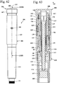
- FIGS. 62 to 96 show an embodiment of an injection device 101.
- the same reference numerals as in the preceding figures indicate like elements.
- the injection device 101 is in the Figures 62 and 63 shown in zero position.
- the injection device 101 has a housing 102 which comprises an upper housing part 103 and a lower housing part 104 arranged on the proximal side of the upper housing part 103.
- a container 105 is arranged with injection liquid, in which a plug 117 is arranged.
- the upper housing part 103 has a viewing window 109, through which a scale is visible.
- an operating element 106 is arranged, which comprises an adjusting sleeve 107 and an actuating knob 108, which are firmly connected to each other.
- adjusting sleeve 107 and actuator button 108 are integrally formed with each other in the embodiment.
- the operating element 106 is also formed in one piece with a driver 113.
- the operating element 106 has an inwardly projecting retaining edge 161, which bears against a retaining edge 160 of an adjustment part 122.
- the operating element 106 is arranged on the distal side of a latching part 126, which is biased by a spring 128 in the distal direction.
- the spring 128 also acts on the operating element 106 via the latching part 126.
- the holder edges 160 and 161 prevent further movement of the operating element 106 in the distal direction.
- the injection device 101 has a longitudinal center axis 110. At the distal end of the injection device 101, a fastening thread 111 is provided for an injection needle.
- the driver 113 is rotatably connected to a feed member 118 which is connected via a first threaded connection 119 with a piston rod 115 of a metering piston 114.
- the metering piston 114 carries on its proximal side a piston disc 116 which bears against the stopper 117 of the container 105.
- the piston rod 115 is rotatably held in a piston guide 131 relative to the housing 102.
- the feed part 118 has the shoulder 89, against which the shoulder 68 of a slide 120 rests.
- the slider 120 is connected to the housing 102 via a second threaded connection 121.
- the slider 120 is non-rotatably connected to an adjusting part 122, which is connected via a third threaded connection 123 with the housing 103.
- the third threaded connection 123 is formed between a threaded part 130 held firmly in the housing 102 and the adjusting part 122.
- the spring 128 is guided.
- a second spring 129 which is designed as a torsion spring and biases the slider 120 in the direction of the zero position of the injection device 101.
- a latching device 125 acts between the locking part 126 and the adjusting part 122.
- a first clutch 124 is provided, which in the Fig. 63 shown zero position is closed. If the adjusting sleeve 107 is rotated, the setting member 122 is entrained via the driver 113 and the first clutch 124. Between the operating element 106 and the latching part 126, a second clutch 127 is provided, which comprises a coupling part 132, and in the in Fig. 63 shown zero position is open. In this position, the operating element 106 can be rotated relative to the latching part 126.
- the coupling part 132 is held axially fixed to the setting part 122 between retaining edges 136 and 137 of the adjusting part 122.
- the coupling part 132 can be axially movable relative to the adjusting part 122.
- the coupling part 132 is rotatably connected to the locking part 126.
- the coupling member 132 is rotatably connected to the housing 102.
- the coupling member 132 is completely within the locking member 126.
- the coupling member 132 is in this position of the second clutch 127 against the control element 106 rotatable.
- the coupling part 132 can also be advantageous for the coupling part 132 to be located completely within the operating element 106 in the open position of the coupling 127 and to be connected in a rotationally fixed manner to the operating element 106 and to be rotatable relative to the detent part 126 and the housing 102.
- the operator rotates the adjusting sleeve 107.
- the adjusting part 122 which is also moved in the direction of the arrow 33 in the distal direction due to the third threaded connection 123, also moves via the non-rotatable connection with the adjusting part 122.
- the spring 128 presses the latching part 126 and the control element 106 against the retaining edge 160 of the adjustment part 122 and guides these components in the distal movement of the adjustment part 122.
- the feed part 118 is rotated and moves due to the first threaded connection 119 in the distal direction.
- the slider 120 is entrained by the adjusting member 122 and moves due to the second threaded connection 121 also in the distal direction.
- the Figures 64 and 65 show the arrangement after setting the maximum dose.
- the number "2" is displayed in the embodiment.
- the locking part 126 has moved partially out of the upper housing part 103.
- the relative axial position of setting member 122 and locking member 126 has not changed, so that the latching device 125 is active during the entire adjustment process.
- the spring 129 is tensioned during the adjustment process due to the relative rotation of slide 120 and housing 103.
- the operation knob 108 is to be displaced in the direction of the arrow 38 in the proximal direction.
- the proximal position of the operating knob 108 is in the FIGS. 66 and 67 shown.
- the operation button 108 can be pushed until the stopper 53 of the adjustment member 122 abuts the operation knob 108.
- the holder edges 160 and 161 have a distance from each other in this position.
- the control element 106 has at its proximal side a pressure edge 112 which bears against the latching part 126. When moving the actuating knob in the proximal direction of the pressure edge 112 acts on the locking member 126 and moves the locking member 126 in the proximal direction.
- the pressure edge 112 comes into the region of the coupling part 132, and the second coupling 127 is closed.
- the coupling part 132 is rotatably connected in this position both with the operating element 106 and with the locking part 126.
- the actuating knob 108 is held against rotation relative to the housing 102.
- the slider 120 acts on the Paragraphs 68 and 89 on the Zuudgeil 118 and moves the Zuudgeil 118 in the proximal direction. Due to the closed second coupling 127, the feed part 118 is connected in a rotationally fixed manner to the housing 102 via the driver 113, the operating element 106, the coupling part 132 and the latching part 126. The slider 120 moves the feed part 118 together with the piston rod 115, which is also secured against rotation relative to the housing 102, in the proximal direction, thereby forcing injection liquid out of the container 5.
- the second coupling 127 of the injection device 101 prevents rotation of the feed part 118 relative to the housing 102 during an injection.
- the second coupling 127 of the injection device 101 replaces the latching device 32 of the injection device 1 (see, for example Fig. 6 ).
- the Figures 68 to 71 show the second clutch 127 in detail.
- Fig. 69 shows, when the clutch 127 is open, the latch 125 is active.
- the first clutch 124 is closed.
- Fig. 71 shows, in the proximal position of the control knob 108, the first clutch 124 is opened and the second clutch 127 is closed.
- the latching device 125 is not active because the locking elements on locking part 126 and adjusting 122 are out of engagement with each other. Actuating knob 108 and locking member 126 are rotatably connected to each other.
- the Figures 72 to 76 show the adjusting part 122 in detail.
- the adjusting part 122 has the latching elements 41 to 44.
- the toothing 52 of the first clutch 124 is arranged on the inner circumference of the adjusting part 122.
- the Figures 77 to 82 show the locking part 126.
- the locking part 126 differs from the locking part 26 by the internal teeth 135 on the distal side of the locking part 126th
- the Figures 83 to 85 show the coupling part 132.
- the coupling part 132 is formed as a ring having an outer toothing 133 on its outer periphery.
- the external toothing 133 cooperates with the internal toothing 135 of the latching part 126, so that the coupling part 132 is held in a rotationally fixed manner in the latching part 126.
- FIGS. 86 to 89 show the driver 113.
- the driver 113 has at the pressure edge 112 an internal toothing 134 which corresponds to the internal toothing 135 of the locking part 126.
- the coupling part 132 protrudes into the internal toothing 134 and thereby rotatably connects the detent part 126 to the driver 113.
- the driver 113 and thus also the feed part 118 are secured against rotation with respect to the housing 102.
- the retaining edge 161 is disposed on the distal side of the toothing 134.
- the Figures 88 and 89 also show the longitudinal webs 63 and teeth 62 of the driver 113th
- the Figures 90 to 93 show the piston guide 131 with the opening 80. Like the FIGS. 91 and 93 show, no latching structure is provided on the piston guide 131. Between the Zuticianil 118 and the piston guide 131 no locking device is necessary, since the Zu Industriesil 118 is pressed with pressed button 108 and closed second clutch 127 via the driver 113 and the second clutch 127 rotatably connected to the locking member 126 and thus to the housing 102. A rotation of the actuating knob 108 and thus the slider 118 when squeezing a set amount of injection liquid is thereby reliably prevented. As the Figures 94 and 96 show the Zuixieil 118 according to no latching arms.
- the feed part 118 is sleeve-shaped and has the longitudinal grooves 86 and the internal thread 88.
- FIGS. 97 to 106 show an embodiment of an injection device 201, the structure of which substantially corresponds to that of the injection device 101.
- the same reference numerals as in the previous figures characterize the same elements.
- the injection device 201 has a housing 202 and an operating element 206.
- the operating element 206 has an actuating button 208.
- Fig. 98 shows, in the housing 202, a locking part 226 via longitudinal grooves 48 and longitudinal webs 70 rotatably and held in the direction of its longitudinal central axis 210 slidably.
- the injection device 201 also has an adjusting part 222, which is arranged radially inside the locking part 226 in the embodiment.
- the latching device 225 comprises a locking element 40 formed on the adjusting part 222, which is resiliently held on a latching arm 39, and latching elements 41, 42, 43 and 44 on the latching part 226.
- FIGS. 99 to 103 show the design of the locking member 226 in detail.
- the latching part 226 In its distal region, the latching part 226 has an internal toothing 135 for the rotationally fixed connection to an external toothing 133 of a coupling part 132.
- the latching elements 41 to 44 are arranged on the inner periphery of the latching part 226 Figures 100 and 102 demonstrate.
- the locking elements 41 to 44 formed as ramp-shaped elevations on the inner circumference of the locking part 226.
- Fig. 103 shows the internal toothing 135, which is interrupted in the embodiment by a plurality of interruptions 235.
- FIGS. 104 to 106 show the adjusting 222 in detail.
- the adjusting part 222 carries in the proximal region on its outer circumference an external thread 47.
- the adjusting part 222 has a toothing 252.
- the toothing 252 is part of a coupling which corresponds to the coupling 124 and serves for the rotationally fixed connection to the operating element 206.
- the operating element 206 carries a not shown, the teeth 252 associated teeth on its inside.
- the latching arm 39 is provided with the latching element 40.
- the function of the injection device 201 corresponds to the function described for the injection device 101.
- the arrangement of the fixed latching elements 41 to 44 on the latching part 226 and the arrangement of the latching arm 39 with the latching element 40 on the adjusting part 222, the demolding of the adjusting member 222 from an injection molding tool in the manufacture of the adjusting member 222 is simplified. If other dose settings and thus other detent positions are desired for an injection device 201, then only the position of the detent elements 41 to 44 on the detent part 226 has to be changed. The complicated to produce adjusting part 222 may remain unchanged.
- the stop for in the Figures 97 and 98 shown zero position between the locking element 40 and the locking element 41 is formed. However, it can also be provided not to form the stop for the zero position between the latching part 226 and the adjusting part 222, but between the slide 120 (FIG. Fig. 63 ) and the housing 202.
- the stop may be formed, for example, by an axial protrusion on the slider 120, which cooperates with a corresponding elevation or a recess on the housing 201.
- the latching device 25, 125, 225 acts in each case between the non-rotatably held in the housing 2, 102, 202 latching part 26, 26 ', 126, 226 and the adjusting part 22, 22', 122, 222, the rotates when setting the dose in the first direction of rotation 45 and when expressing the dose in the opposite direction of rotation 51. Due to the fact that the adjustment part 22, 22 ', 122, 222 turns back when the dose is pressed out, each detent position is assigned a defined position of the adjustment part 22, 22', 122, 222 relative to the detent part 26, 126, 226. As a result, different distances between the locking positions can be provided.
- the operator only has to override intended detent positions. Only in the injection device 1, but not in the injection devices 101, 201 provided second latching device 32 intermediate steps of a latching device are to be overcome, the resistance of which, however, is significantly lower than that of the latching device 25. This results in an ergonomic, easy operation.
Landscapes
- Health & Medical Sciences (AREA)
- Vascular Medicine (AREA)
- Engineering & Computer Science (AREA)
- Anesthesiology (AREA)
- Biomedical Technology (AREA)
- Heart & Thoracic Surgery (AREA)
- Hematology (AREA)
- Life Sciences & Earth Sciences (AREA)
- Animal Behavior & Ethology (AREA)
- General Health & Medical Sciences (AREA)
- Public Health (AREA)
- Veterinary Medicine (AREA)
- Infusion, Injection, And Reservoir Apparatuses (AREA)
Description
Die Erfindung betrifft ein Injektionsgerät der im Oberbegriff des Anspruchs 1 angegebenen Gattung.The invention relates to an injection device of the type specified in the preamble of
Aus der
Aus der
Aus der
Das aus der
Der vorliegenden Erfindung liegt die Aufgabe zugrunde, ein Injektionsgerät der gattungsgemäßen Art zu schaffen, das die Anordnung mehrerer Raststellungen in unterschiedlichen Abständen ermöglicht.The present invention has for its object to provide an injection device of the generic type, which allows the arrangement of several locking positions at different distances.
Diese Aufgabe wird durch ein Injektionsgerät mit den Merkmalen des Anspruchs 1 gelöst.This object is achieved by an injection device having the features of
Die vorliegende Erfindung sieht vor, dass jeder Raststellung eine eindeutige Drehlage des Einstellteils gegenüber dem Gehäuse zugeordnet ist. Dadurch können die benötigten Raststellungen mit unterschiedlichen Abständen zueinander angeordnet werden. Beispielsweise könnte für die eingangs beispielhaft beschriebene Therapie ein Injektionsgerät vorgesehen werden, das genau drei Raststellungen bei 0,01 ml für den Priming-Vorgang und 0,20 ml und 0,25 ml für die zu injizierenden Dosen bereitstellt. Dadurch wird die Bedienung des Injektionsgeräts erheblich vereinfacht. Dadurch, dass das Zustellteil, der Schieber und das Einstellteil über unterschiedliche Gewindeverbindungen in axialer Richtung bewegt werden, sind für das Einstellteil und Schieber und Zustellteil unterschiedliche axiale Wege möglich. Das Injektionsgerät kann so ausgelegt werden, dass die Injektion vom Bediener manuell durchgeführt werden kann, so dass der Bediener die Injektionsgeschwindigkeit selbst steuern kann.The present invention provides that each detent position is assigned a unique rotational position of the adjustment member relative to the housing. As a result, the required locking positions can be arranged with different distances from each other. For example, an injection device could be provided for the therapy described at the outset by way of example, which provides exactly three detent positions at 0.01 ml for the priming procedure and 0.20 ml and 0.25 ml for the doses to be injected. This considerably simplifies the operation of the injection device. Characterized in that the Zustellteil, the slider and the adjusting member are moved via different threaded connections in the axial direction, different axial paths are possible for the setting part and slide and Zustellteil. The injection device can be designed so that the injection can be performed manually by the operator so that the operator can control the injection speed himself.
Die Rasteinrichtung wirkt zwischen dem Einstellteil und dem Gehäuse. Dabei muss die Rasteinrichtung nicht von dem Einstellteil und dem Gehäuse gebildet sein, sondern kann auch an Bauteilen angeordnet sein, die drehfest mit dem Einstellteil bzw. dem Gehäuse verbunden sind. Die Rasteinrichtung ist demnach von dem Einstellteil oder einem drehfest mit dem Einstellteil verbundenen Bauteil und von dem Gehäuse oder einem drehfest mit dem Gehäuse verbundenen Bauteil gebildet.The latching device acts between the adjustment part and the housing. In this case, the latching device need not be formed by the setting part and the housing, but may also be arranged on components which are non-rotatably connected to the setting part or the housing. The latching device is therefore formed by the setting part or a rotatably connected to the setting member and the housing or a rotatably connected to the housing component.
Bei dem Injektionsgerät gemäß der
Vorteilhaft umfasst die Rasteinrichtung ein Rastteil, das unabhängig vom Einstellteil in Richtung der Längsmittelachse des Injektionsgeräts verschiebbar ist und das drehfest mit dem Gehäuse verbunden ist. Vorteilhaft ist an dem Rastteil mindestens ein erstes Rastelement angeordnet. Durch die Anordnung des Rastelements an einem axial verschiebbaren Rastteil kann das Rastelement durch Verschieben in Richtung der Längsmittelachse des Injektionsgeräts in eine Stellung gebracht werden, in der es nicht wirksam ist. An dem Einstellteil ist vorteilhaft mindestens ein zweites Rastelement angeordnet. Das mindestens eine erste Rastelement und das mindestens eine zweite Rastelement definieren vorteilhaft in einer ersten axialen Stellung von Rastteil und Einstellteil die mindestens eine Raststellung und sind in mindestens einer zweiten axialen Stellung von Rastteil und Einstellteil unabhängig von der relativen Drehlage des Einstellteils zum Rastteil außer Eingriff. Dadurch kann sich das Einstellteil gegenüber dem Rastteil beim Auspressen einer auszupressenden Menge an Injektionsflüssigkeit zurückstellen, ohne dass die Raststellungen hörbar und spürbar für den Benutzer sind und vom Benutzer zu überwinden sind. Dadurch ergibt sich eine einfache und ergonomische Bedienung. Vorteilhaft besitzt das Injektionsgerät eine Feder, die das Rastteil in Richtung auf die erste axiale Stellung vorspannt.Advantageously, the latching device comprises a latching part, which is displaceable independently of the adjusting part in the direction of the longitudinal center axis of the injection device and which is non-rotatably connected to the housing. At least one first latching element is advantageously arranged on the latching part. By arranging the locking element on an axially displaceable locking part, the locking element can be brought by displacement in the direction of the longitudinal central axis of the injection device in a position in which it is not effective. At least one second latching element is advantageously arranged on the setting part. The at least one first latching element and the at least one second latching element advantageously define the at least one latching position in a first axial position of the latching part and the adjusting element and are disengaged from the relative rotary position of the adjusting part relative to the latching part in at least one second axial position of latching part and adjusting part. As a result, the adjusting part can be set back relative to the locking part when squeezing out an amount of injection liquid to be squeezed out, without the locking positions being audible and noticeable to the user and to be overcome by the user. This results in a simple and ergonomic Service. Advantageously, the injection device has a spring which biases the locking part in the direction of the first axial position.
Vorteilhaft ist das Einstellteil drehfest mit dem Schieber verbunden. Der Schieber wirkt beim Auspressen von Injektionsflüssigkeit aus dem Behälter vorteilhaft derart auf das Zustellteil, dass der Schieber bei einer Bewegung in proximale Richtung das Zustellteil in proximaler Richtung verschiebt. Der Dosierkolben ist vorteilhaft drehfest im Gehäuse gehalten. Beim Einstellen einer auszupressenden Menge an Injektionsflüssigkeit drehen sich Einstellteil, Schieber und Zustellteil vorteilhaft gegenüber dem Gehäuse über ihre jeweilige Gewindeverbindung. Beim Auspressen einer auszupressenden Menge an Injektionsflüssigkeit ist das Zustellteil vorteilhaft drehfest geführt und bewegt aufgrund seiner Bewegung in proximale Richtung den Dosierkolben mit. Das Einstellteil und der Schieber drehen sich beim Auspressen der auszupressenden Menge an Injektionsflüssigkeit zurück in ihre Ausgangslage.Advantageously, the adjusting member rotatably connected to the slide. When the injection liquid is pressed out of the container, the slider advantageously acts on the feed part in such a way that the slider shifts the feed part in the proximal direction during a movement in the proximal direction. The metering is advantageously rotatably held in the housing. When setting a quantity of injection liquid to be squeezed out, the adjusting part, slider and infeed part advantageously rotate relative to the housing via their respective threaded connection. When squeezing out an amount of injection liquid to be squeezed, the feed part is advantageously guided in a rotationally fixed manner and, due to its movement in the proximal direction, moves the dosing piston with it. The adjusting part and the slide turn back to their original position when pressing out the amount of injection liquid to be squeezed out.
Vorteilhaft besitzt das Injektionsgerät einen Mitnehmer, der drehfest mit dem Zustellteil verbunden ist. In Richtung der Längsmittelachse des Injektionsgeräts sind Mitnehmer und Zustellteil vorteilhaft relativ zueinander beweglich. Insbesondere besitzt das Injektionsgerät eine Kupplung, die in einer ersten Stellung das Einstellteil drehfest mit einem Mitnehmer verbindet, und in einer zweiten Stellung eine Relativdrehung des Einstellteils gegenüber dem Mitnehmer zulässt. Der Mitnehmer ist vorteilhaft drehfest mit dem Zustellteil verbunden. Das Verstellen der Kupplung von der ersten Stellung in die zweite Stellung erfolgt vorteilhaft durch Verschieben eines Betätigungsknopfes des Injektionsgerätes in proximale Richtung. Vorteilhaft ist das Rastteil in Richtung der Längsmittelachse derart an den Betätigungsknopf gekoppelt, dass eine Bewegung des Betätigungsknopfes in proximale Richtung eine Bewegung des Rastteils in proximale Richtung bewirkt.Advantageously, the injection device has a driver, which is rotatably connected to the Zustellteil. In the direction of the longitudinal center axis of the injection device, the driver and the feed part are advantageously movable relative to each other. In particular, the injection device has a coupling which rotatably connects the adjusting member in a first position with a driver, and in a second position permits a relative rotation of the adjusting member relative to the driver. The driver is advantageous rotatably connected to the Zustellteil. The adjustment of the coupling from the first position to the second position is advantageously carried out by moving an actuating knob of the injection device in the proximal direction. Advantageously, the locking part in the direction of the longitudinal central axis is coupled to the actuating button such that a movement of the actuating knob in the proximal direction causes a movement of the locking part in the proximal direction.
Zum Einstellen der auszupressenden Menge an Injektionsflüssigkeit besitzt das Injektionsgerät vorteilhaft eine Stellhülse. Bei einer ersten Ausführungsform des Injektionsgeräts ist die Stellhülse fest mit dem Einstellteil verbunden. Die Stellhülse ist insbesondere einteilig mit dem Einstellteil verbunden. Vorteilhaft wirkt der Betätigungsknopf über ein Druckstück auf das Rastteil, wobei das Druckstück drehbar gegenüber dem Betätigungsknopf ist und drehfest mit dem Einstellteil verbunden ist. Das Einstellteil ist mit der Stellhülse vorteilhaft über einen Ringsteg verbunden, der mindestens eine Öffnung besitzt, durch die ein Drucksteg des Druckstücks ragt. Beim Auspressen der auszupressenden Menge an Injektionsflüssigkeit ist der Betätigungsknopf vorteilhaft drehfest geführt. Das Einstellteil dreht sich zusammen mit der Stellhülse zurück in seine Ausgangslage. Das Druckstück kann mit dem Einstellteil und der Stellhülse gegenüber dem Betätigungsknopf rotieren. Dadurch ergibt sich ein einfacher Aufbau. Vorteilhaft ist das Zustellteil über eine zweite Rasteinrichtung mit dem Gehäuse verbunden, wobei die Rasteinrichtung mindestens einen Längssteg umfasst, an dem das Zustellteil beim Auspressen einer eingestellten Menge an Injektionsflüssigkeit geführt ist. Die zweite Rasteinrichtung stellt sicher, dass sich das Zustellteil und der drehfest mit dem Zustellteil verbundene Betätigungsknopf beim Auspressen der eingestellten Menge an Injektionsflüssigkeit nicht gegenüber dem Gehäuse drehen und dadurch die auszupressende Menge an Injektionsflüssigkeit verringern können. Die zweite Rasteinrichtung ist gegenüber der ersten Rasteinrichtung zwischen Einstellteil und Rastteil vorteilhaft sehr schwach ausgelegt. Die Rastschritte der zweiten Rasteinrichtung sind so ausgelegt, dass alle einzustellenden Dosiswerte dem Vielfachen der Rastschritte entsprechen. Die Dosis für den Priming-Vorgang entspricht vorteilhaft mindestens dem Rastschritt der zweiten Rasteinrichtung.To set the amount of injection liquid to be squeezed, the injection device advantageously has a setting sleeve. In a first embodiment of the Injection device, the adjusting sleeve is firmly connected to the setting part. The adjusting sleeve is in particular integrally connected to the setting part. Advantageously, the actuating knob acts via a pressure piece on the locking part, wherein the pressure piece is rotatable relative to the actuating button and is non-rotatably connected to the setting part. The adjusting member is advantageously connected to the adjusting sleeve via an annular web, which has at least one opening through which a pressure ridge of the pressure piece protrudes. When squeezing out the amount of injection liquid to be squeezed, the actuating knob is advantageously guided in a rotationally fixed manner. The adjusting part rotates together with the adjusting sleeve back to its original position. The pressure piece can rotate with the adjusting part and the adjusting sleeve relative to the operating knob. This results in a simple structure. Advantageously, the infeed part is connected to the housing via a second latching device, wherein the latching device comprises at least one longitudinal web on which the infeed part is guided when a set amount of injection liquid is pressed out. The second locking device ensures that the Zustellteil and the rotatably connected to the Zustellteil operating button when pressing the set amount of injection liquid does not rotate relative to the housing and thereby can reduce the amount of injection liquid to be squeezed out. The second locking device is advantageously designed very weak compared to the first locking device between setting and locking part. The latching steps of the second latching device are designed so that all the dose values to be set correspond to the multiple of the latching steps. The dose for the priming process advantageously corresponds at least to the latching step of the second latching device.
Bei einer weiteren Ausführungsvariante kann vorgesehen sein, dass die Stellhülse fest mit dem Betätigungsknopf verbunden ist. Vorteilhaft besitzt das Injektionsgerät eine zweite Kupplung, die in der distalen Position des Betätigungsknopfes eine Relativdrehung des Mitnehmers gegenüber dem Rastteil zulässt und in einer proximalen Position des Betätigungsknopfes den Mitnehmer drehfest mit dem Rastteil verbindet. Dadurch ergibt sich ein einfacher Aufbau des Injektionsgerätes. Ein einfacher Aufbau der zweiten Kupplung ergibt sich, wenn der Mitnehmer und das Rastteil jeweils eine Verzahnung besitzen. Am Einstellteil ist vorteilhaft ein Kupplungsteil angeordnet, das eine Gegenverzahnung trägt. In der distalen Position des Betätigungsknopfes wirkt die Gegenverzahnung nur mit einer der Verzahnungen zusammen. In der proximalen Position des Betätigungsknopfes ist die Gegenverzahnung mit beiden Verzahnungen drehfest verbunden und verbindet dadurch Mitnehmer und Rastteil drehfest miteinander. Vorteilhaft ist das Kupplungsteil gegenüber dem Einstellteil drehbar und in Richtung der Längsmittelachse ortsfest am Einstellteil gehalten. Das Kupplungsteil kann dabei gegenüber dem Einstellteil geringfügig axial verschiebbar sein. Das Kupplungsteil muss derart ortsfest am Einstellteil gehalten sein, dass sichergestellt ist, dass das Kupplungsteil in der proximalen Position des Betätigungsknopfes sowohl mit der Verzahnung am Mitnehmer als auch mit der Verzahnung am Rastteil drehfest verbunden ist und in der distalen Position des Betätigungsknopfs nur mit einer der Verzahnungen. Ein einfacher Aufbau ergibt sich, wenn das Kupplungsteil in der distalen Position des Bedienknopfes nur mit der Verzahnung des Rastteils zusammenwirkt.In a further embodiment, it can be provided that the adjusting sleeve is firmly connected to the actuating button. Advantageously, the injection device has a second clutch, which allows in the distal position of the actuating knob relative rotation of the driver relative to the locking part and rotatably connected in a proximal position of the actuating knob the driver with the locking part. This results in a simple construction of the injection device. A simple construction of the second coupling results when the driver and the locking member each one Own gearing. On adjusting part, a coupling part is advantageously arranged, which carries a counter-toothing. In the distal position of the actuating knob, the counter-toothing interacts with only one of the teeth. In the proximal position of the actuating knob, the counter-toothing is rotatably connected to both gears and thereby connects driver and locking member rotatably together. Advantageously, the coupling part is rotatable relative to the adjusting part and held stationary in the direction of the longitudinal center axis on the adjusting part. The coupling part can be slightly axially displaceable relative to the adjustment. The coupling part must be held so stationary on the adjusting that it is ensured that the coupling member is rotatably connected in the proximal position of the actuating knob both with the teeth on the driver and with the teeth on the locking member and in the distal position of the operating knob with only one of gearing. A simple structure results when the coupling part cooperates in the distal position of the control knob only with the teeth of the locking part.
Vorteilhaft besitzt das Injektionsgerät eine Feder, die zwischen dem Schieber und dem Gehäuse wirkt und die den Schieber in der zweiten Drehrichtung vorspannt. Die Feder ist insbesondere eine Torsionsfeder. Die Vorspannung des Schiebers in der zweiten Drehrichtung bewirkt, dass sich der Schieber aufgrund der Federkraft zurück zur nächst niedrigen Raststellung der ersten Rasteinrichtung stellt, wenn keine vorgesehene Menge an Injektionsflüssigkeit eingestellt ist. Dadurch wird das Einstellen einer nicht vorgesehenen Menge an Injektionsflüssigkeit, der keine Raststellung zugeordnet ist, auf einfache Weise verhindert. Gleichzeitig unterstützt die Feder das Auspressen der eingestellten Menge an Injektionsflüssigkeit.Advantageously, the injection device has a spring which acts between the slider and the housing and which biases the slider in the second direction of rotation. The spring is in particular a torsion spring. The bias of the slider in the second direction of rotation causes the slider is due to the spring force back to the next low detent position of the first locking device, if no intended amount of injection liquid is set. As a result, the setting of an unintended amount of injection liquid, which is assigned no detent position, prevented in a simple manner. At the same time, the spring helps to squeeze out the set amount of injection liquid.
Ausführungsbeispiele der Erfindung werden im Folgenden anhand der Zeichnung erläutert. Es zeigen:
- Fig. 1
- eine Seitenansicht eines Injektionsgerätes,
- Fig. 2
- einen Schnitt durch das Injektionsgerät aus
Fig. 1 entlang der Linie II-II inFig. 1 , - Fig. 3
- das Injektionsgerät aus
Fig. 1 nach dem Einstellen der Maximaldosis, - Fig. 4
- einen Schnitt entlang der Linie IV-IV in
Fig. 3 , - Fig. 5
- das Injektionsgerät aus
Fig. 1 bei eingestellter Maximaldosis nach dem Verschieben des Betätigungsknopfes in proximale Richtung, - Fig. 6
- einen Schnitt entlang der Linie VI-VI in
Fig. 5 , - Fig. 7
- eine Seitenansicht von Rastteil und Einstellteil in der in
Fig. 1 gezeigten Stellung des Injektionsgerätes, - Fig. 8
- einen Schnitt entlang der Linie VIII-VIII in
Fig. 7 , - Fig. 9
- eine Seitenansicht von Einstellteil und Rastteil nach dem Betätigen des Betätigungsknopfes,
- Fig. 10
- einen Schnitt entlang der Linie X-X in
Fig. 9 , - Fig. 11
- eine Seitenansicht des Einstellteils,
- Fig. 12
- einen Schnitt entlang der Linie XII-XII in
Fig. 11 , - Fig. 13
- eine Seitenansicht auf das Einstellteil in Richtung des Pfeils XIII in
Fig. 11 , - Fig. 14
- einen Schnitt durch das Einstellteil entlang der Linie XIV-XIV in
Fig. 11 , - Fig. 15
- einen Schnitt durch das Einstellteil entlang der Linie XV-XV in
Fig. 14 , - Fig. 16
- eine Draufsicht auf das Einstellteil in Richtung des Pfeils XVI in
Fig. 13 , - Fig. 17
und 18 - perspektivische Darstellungen des Rastteils,
- Fig. 19
- eine Seitenansicht des Rastteils aus
den Figuren 17 ,und 18 - Fig. 20
- eine Seitenansicht des Rastteils in Richtung des Pfeils XX in
Fig. 19 , - Fig. 21
- einen Schnitt durch das Rastteil entlang der Linie XXI-XXI in
Fig. 20 , - Fig. 22
und 23 - perspektivische Darstellungen des Druckstücks,
- Fig. 24
- eine Seitenansicht des Druckstücks,
- Fig. 25
- eine Ansicht des Druckstücks in Richtung des Pfeils XXV in
Fig. 24 , - Fig. 26
- eine Seitenansicht des Mitnehmers,
- Fig. 27
- einen Schnitt entlang der Linie XXVII-XXVII in
Fig. 26 , - Fig. 28
- einen Schnitt entlang der Linie XXVIII-XXVIII in
Fig. 26 , - Fig. 29
und 30 - perspektivische Darstellungen des Schiebers,
- Fig. 31
- eine Seitenansicht des Schiebers,
- Fig. 32
- eine Ansicht des Schiebers in Richtung des Pfeils XXXII in
Fig. 31 , - Fig. 33
- eine Seitenansicht des oberen Gehäuseteils des Injektionsgerätes,
- Fig. 34
- einen Schnitt entlang der Linie XXXIV-XXXIV in
Fig. 33 , - Fig. 35
- einen Schnitt entlang der Linie XXXV-XXXV in
Fig. 34 , - Fig. 36
- einen Schnitt entlang der Linie XXXVI-XXXVI in
Fig. 33 , - Fig. 37
- einen Schnitt entlang der Linie XXXVII-XXXVII in
Fig. 33 , - Fig. 38
und 39 - perspektivische Darstellungen des Gewindeteils des Injektionsgeräts,
- Fig. 40
- eine Ansicht auf das Gewindeteil von oben,
- Fig. 41
- eine Seitenansicht des Gewindeteils,
- Fig. 42
- einen Schnitt durch das Gewindeteil entlang der Linie XLII-XLII in
Fig. 41 , - Fig. 43
- eine Seitenansicht der Feder des Injektionsgerätes,
- Fig. 44
und 45 - perspektivische Darstellungen der Kolbenführung,
- Fig. 46
- eine Seitenansicht der Kolbenführung,
- Fig. 47
- eine Ansicht der Kolbenführung in Richtung des Pfeils XLVII in
Fig. 46 , - Fig. 48
- eine Seitenansicht des Zustellteils,
- Fig. 49
- einen Schnitt entlang der Linie XLIX-XLIX in
Fig. 48 , - Fig. 50
- einen Schnitt entlang der Linie L-L in
Fig. 48 , - Fig. 51
- einen Schnitt entlang der Linie LI-LI in
Fig. 48 , - Fig. 52
- Einstellteil und Rastteil eines Ausführungsbeispiels des Injektionsgerätes in perspektivischer, auseinandergezogener Darstellung,
- Fig. 53
- die Anordnung aus
Fig. 52 in Seitenansicht, - Fig. 54
- einen Schnitt entlang der Linie LIV-LIV in
Fig. 53 , - Fig. 55
- einen Schnitt entlang der Linie LV-LV in
Fig. 53 , - Fig. 56
- eine perspektivische Darstellung des Rastteils aus
Fig. 52 , - Fig. 57
- eine Draufsicht auf das Rastteil aus
Fig. 56 , - Fig. 58
- eine Seitenansicht des Rastteils aus
Fig. 56 , - Fig. 59
- eine Seitenansicht des Einstellteils aus
Fig. 52 , - Fig. 60
- eine Ansicht des Einstellteils in Richtung des Pfeils LX in
Fig. 59 , - Fig. 61
- einen Schnitt entlang der Linie LXI-LXI in
Fig. 59 , - Fig. 62
- eine Seitenansicht eines Ausführungsbeispiels eines Injektionsgerätes,
- Fig. 63
- einen Schnitt entlang der Linie LXIII-LXIII in
Fig. 62 , - Fig. 64
- das Injektionsgerät aus
Fig. 62 nach dem Einstellen der Maximaldosis, - Fig. 65
- einen Schnitt entlang der Linie LXV-LXV in
Fig. 64 , - Fig. 66
- das Injektionsgerät aus
Fig. 64 nach dem Verschieben des Betätigungsknopfes in proximale Richtung, - Fig. 67
- einen Schnitt entlang der Linie LXVII-LXVII in
Fig. 66 , - Fig. 68
- Einstellteil, Rastteil und Feder des Injektionsgerätes aus
Fig. 64 in Seitenansicht, - Fig. 69
- einen Schnitt entlang der Linie LXIX-LXIX in
Fig. 68 , - Fig. 70
- die Anordnung aus
Fig. 68 nach dem Verschieben des Betätigungsknopfes in proximale Richtung, - Fig. 71
- einen Schnitt entlang der Linie LXXI-LXXI in
Fig. 70 , - Fig. 72
- eine perspektivische Darstellung des Einstellteils des Injektionsgeräts aus
Fig. 62 , - Fig. 73
- eine Seitenansicht des Einstellteils aus
Fig. 72 , - Fig. 74
- einen Schnitt entlang der Linie LXXIV-LXXIV in
Fig. 73 , - Fig. 75
- einen Schnitt entlang der Linie LXXV-LXXV in
Fig. 73 , - Fig. 76
- einen Schnitt entlang der Linie LXXVI-LXXVI in
Fig. 74 , - Fig. 77
und 78 - perspektivische Darstellungen des Rastteils des Injektionsgerätes aus
Fig. 62 , - Fig. 79
- eine Seitenansicht des Rastteils aus
Fig. 77 , - Fig. 80
- einen Schnitt entlang der Linie LXXX-LXXX in
Fig. 79 , - Fig. 81
- einen Schnitt entlang der Linie LXXXI-LXXXI in
Fig. 79 , - Fig. 82
- einen Schnitt entlang der Linie LXXXII-LXXXII in
Fig. 79 , - Fig. 83
- das Kupplungsteil des Injektionsgeräts aus
Fig. 62 in perspektivischer Darstellung, - Fig. 84
und 85 - Seitenansichten des Kupplungsteils aus
Fig. 83 , - Fig. 86
- eine Seitenansicht des Mitnehmers des Injektionsgerätes aus
Fig. 62 , - Fig. 87
- einen Schnitt entlang der Linie LXXXVII-LXXXVII in
Fig. 86 , - Fig. 88
- eine Ansicht des Mitnehmers in Richtung des Pfeils LXXXVIII in
Fig. 87 , - Fig. 89
- einen Schnitt entlang der Linie LXXXIX-LXXXIX in
Fig. 86 , - Fig. 90
und 91 - perspektivische Darstellungen der Kolbenführung des Injektionsgeräts aus
Fig. 62 , - Fig. 92
- eine Seitenansicht der Kolbenführung aus
Fig. 90 , - Fig. 93
- eine Ansicht der Kolbenführung in Richtung des Pfeils XCIII in
Fig. 92 , - Fig. 94
- eine Seitenansicht des Zustellteils des Injektionsgeräts aus
Fig. 62 , - Fig. 95
- einen Schnitt entlang der Linie XCV-XCV in
Fig. 94 , - Fig. 96
- einen Schnitt entlang der Linie XCVI-XCVI in
Fig. 94 , - Fig. 97
- eine Seitenansicht eines Ausführungsbeispiels eines Injektionsgerätes,
- Fig. 98
- einen Schnitt entlang der Linie XCVIII-XCVIII in
Fig. 101 , - Fig. 99 und 100
- perspektivische Darstellungen eines Rastteils des Injektionsgeräts aus
Fig. 97 , - Fig. 101
- eine Seitenansicht des Rastteils aus
Fig. 99 , - Fig. 102
- einen Schnitt entlang der Linie CII-CII in
Fig. 101 , - Fig. 103
- einen Schnitt entlang der Linie CIII-CIII in
Fig. 101 , - Fig. 104
- eine perspektivische Darstellung eines Einstellteils des Injektionsgeräts aus
Fig. 97 , - Fig. 105
- eine Seitenansicht des Einstellteils aus
Fig. 104 , - Fig. 106
- eine Schnitt entlang der Linie CVI-CVI in
Fig. 105 .
- Fig. 1
- a side view of an injection device,
- Fig. 2
- a section through the injection device
Fig. 1 along the line II-II inFig. 1 . - Fig. 3
- the injection device off
Fig. 1 after setting the maximum dose, - Fig. 4
- a section along the line IV-IV in
Fig. 3 . - Fig. 5
- the injection device off
Fig. 1 at set maximum dose after moving the actuating knob in the proximal direction, - Fig. 6
- a section along the line VI-VI in
Fig. 5 . - Fig. 7
- a side view of locking part and adjustment in the in
Fig. 1 shown position of the injection device, - Fig. 8
- a section along the line VIII-VIII in
Fig. 7 . - Fig. 9
- a side view of setting and locking part after pressing the operating knob,
- Fig. 10
- a section along the line XX in
Fig. 9 . - Fig. 11
- a side view of the adjustment,
- Fig. 12
- a section along the line XII-XII in
Fig. 11 . - Fig. 13
- a side view of the adjustment in the direction of arrow XIII in
Fig. 11 . - Fig. 14
- a section through the adjustment along the line XIV-XIV in
Fig. 11 . - Fig. 15
- a section through the adjustment along the line XV-XV in
Fig. 14 . - Fig. 16
- a plan view of the adjustment in the direction of arrow XVI in
Fig. 13 . - FIGS. 17 and 18
- perspective views of the locking part,
- Fig. 19
- a side view of the locking part of the
FIGS. 17 and 18 . - Fig. 20
- a side view of the locking part in the direction of arrow XX in
Fig. 19 . - Fig. 21
- a section through the locking part along the line XXI-XXI in
Fig. 20 . - FIGS. 22 and 23
- perspective views of the pressure piece,
- Fig. 24
- a side view of the pressure piece,
- Fig. 25
- a view of the pressure piece in the direction of arrow XXV in
Fig. 24 . - Fig. 26
- a side view of the driver,
- Fig. 27
- a section along the line XXVII-XXVII in
Fig. 26 . - Fig. 28
- a section along the line XXVIII-XXVIII in
Fig. 26 . - FIGS. 29 and 30
- perspective views of the slide,
- Fig. 31
- a side view of the slider,
- Fig. 32
- a view of the slider in the direction of arrow XXXII in
Fig. 31 . - Fig. 33
- a side view of the upper housing part of the injection device,
- Fig. 34
- a section along the line XXXIV-XXXIV in
Fig. 33 . - Fig. 35
- a section along the line XXXV-XXXV in
Fig. 34 . - Fig. 36
- a section along the line XXXVI-XXXVI in
Fig. 33 . - Fig. 37
- a section along the line XXXVII-XXXVII in
Fig. 33 . - FIGS. 38 and 39
- perspective views of the threaded portion of the injection device,
- Fig. 40
- a view of the threaded part from above,
- Fig. 41
- a side view of the threaded part,
- Fig. 42
- a section through the threaded portion along the line XLII-XLII in
Fig. 41 . - Fig. 43
- a side view of the spring of the injection device,
- FIGS. 44 and 45
- perspective views of the piston guide,
- Fig. 46
- a side view of the piston guide,
- Fig. 47
- a view of the piston guide in the direction of arrow XLVII in
Fig. 46 . - Fig. 48
- a side view of the delivery part,
- Fig. 49
- a section along the line XLIX-XLIX in
Fig. 48 . - Fig. 50
- a section along the line LL in
Fig. 48 . - 51
- a section along the line LI-LI in
Fig. 48 . - Fig. 52
- Setting part and locking part of an embodiment of the injection device in a perspective, exploded view,
- Fig. 53
- the arrangement
Fig. 52 in side view, - Fig. 54
- a section along the line LIV-LIV in
Fig. 53 . - Fig. 55
- a section along the line LV-LV in
Fig. 53 . - Fig. 56
- a perspective view of the locking part
Fig. 52 . - Fig. 57
- a plan view of the locking part
Fig. 56 . - Fig. 58
- a side view of the locking part
Fig. 56 . - Fig. 59
- a side view of the adjustment of
Fig. 52 . - Fig. 60
- a view of the adjustment in the direction of arrow LX in
Fig. 59 . - Fig. 61
- a section along the line LXI-LXI in
Fig. 59 . - Fig. 62
- a side view of an embodiment of an injection device,
- Fig. 63
- a section along the line LXIII-LXIII in
Fig. 62 . - Fig. 64
- the injection device off
Fig. 62 after setting the maximum dose, - Fig. 65
- a section along the line LXV-LXV in
Fig. 64 . - Fig. 66
- the injection device off
Fig. 64 after moving the actuating knob in the proximal direction, - Fig. 67
- a section along the line LXVII-LXVII in
Fig. 66 . - Fig. 68
- Setting part, locking part and spring of the injection device off
Fig. 64 in side view, - Fig. 69
- a section along the line LXIX-LXIX in
Fig. 68 . - Fig. 70
- the arrangement
Fig. 68 after moving the actuating knob in the proximal direction, - Fig. 71
- a section along the line LXXI-LXXI in
Fig. 70 . - Fig. 72
- a perspective view of the adjustment of the injection device
Fig. 62 . - Fig. 73
- a side view of the adjustment of
Fig. 72 . - Fig. 74
- a section along the line LXXIV-LXXIV in
Fig. 73 . - Fig. 75
- a section along the line LXXV-LXXV in
Fig. 73 . - Fig. 76
- a section along the line LXXVI-LXXVI in
Fig. 74 . - FIGS. 77 and 78
- perspective views of the locking part of the injection device
Fig. 62 . - Fig. 79
- a side view of the locking part
Fig. 77 . - Fig. 80
- a section along the line LXXX-LXXX in
Fig. 79 . - Fig. 81
- a section along the line LXXXI-LXXXI in
Fig. 79 . - Fig. 82
- a section along the line LXXXII-LXXXII in
Fig. 79 . - Fig. 83
- the coupling part of the injection device
Fig. 62 in perspective, - FIGS. 84 and 85
- Side views of the coupling part
Fig. 83 . - Fig. 86
- a side view of the driver of the injection device
Fig. 62 . - Fig. 87
- a section along the line LXXXVII-LXXXVII in
Fig. 86 . - Fig. 88
- a view of the driver in the direction of arrow LXXXVIII in
Fig. 87 . - Fig. 89
- a section along the line LXXXIX-LXXXIX in
Fig. 86 . - Figs. 90 and 91
- perspective views of the piston guide of the injection device
Fig. 62 . - Fig. 92
- a side view of the piston guide
Fig. 90 . - Fig. 93
- a view of the piston guide in the direction of arrow XCIII in
Fig. 92 . - Fig. 94
- a side view of the Zustellteils of the injection device
Fig. 62 . - Fig. 95
- a section along the line XCV-XCV in
Fig. 94 . - Fig. 96
- a section along the line XCVI-XCVI in
Fig. 94 . - Fig. 97
- a side view of an embodiment of an injection device,
- Fig. 98
- a section along the line XCVIII-XCVIII in
Fig. 101 . - FIGS. 99 and 100
- perspective views of a locking part of the injection device
Fig. 97 . - Fig. 101
- a side view of the locking part
Fig. 99 . - Fig. 102
- a section along the line CII-CII in
Fig. 101 . - Fig. 103
- a section along the line CIII-CIII in
Fig. 101 . - Fig. 104
- a perspective view of an adjustment of the injection device
Fig. 97 . - Fig. 105
- a side view of the adjustment of
Fig. 104 . - Fig. 106
- a section along the line CVI-CVI in
Fig. 105 ,
Die
Das proximale Ende des Injektionsgerätes 1 ist das Ende, an dem die Injektionsnadel 12 angeordnet ist. Das distale Ende des Injektionsgerätes 1 ist das der Injektionsnadel 12 abgewandt liegende Ende. Mit "proximal" wird die Seite des Injektionsgerätes 1 bezeichnet, die bei einer Injektion der Einstichstelle zugewandt liegt und mit "distal" die Seite, die der Einstichstelle abgewandt liegt. Die proximale Richtung bezeichnet die Injektionsrichtung, also die Richtung zur Injektionsnadel 12 hin bzw. die Richtung, in der die Injektionsflüssigkeit aus dem Behälter 5 ausgepresst wird. Die distale Richtung bezeichnet die entgegengesetzte Richtung, also von der Injektionsnadel 12 weg.The proximal end of the
Das Injektionsgerät 1 besitzt ein Bedienelement 6, das im Ausführungsbeispiel mehrteilig ausgebildet ist und eine Stellhülse 7 und einen Betätigungsknopf 8 besitzt. Am oberen Gehäuseteil 3 ist ein Sichtfenster 9 vorgesehen, durch das eine Skala sichtbar ist. Die
Die Kolbenstange 15 ist über eine zwischen dem oberen Gehäuseteil 3 und dem unteren Gehäuseteil 4 gehaltene Kolbenführung 31 drehfest im Gehäuse 2 gehalten. Die Kolbenführung 31 ist dabei drehfest mit dem oberen Gehäuseteil 3 verbunden. Der Mitnehmer 13 ist über eine Kupplung 24 mit einem Einstellteil 22 verbunden. Das Einstellteil 22 ist fest mit der Stellhülse 7 verbunden, im Ausführungsbeispiel einteilig mit dieser ausgeführt. In der in
Zwischen dem Gewindeteil 30 bzw. dem Gehäuse 2 und dem Schieber 20 wirkt eine Feder 29, die vorteilhaft als Torsionsfeder ausgebildet ist. Die Feder 29 spannt den Schieber 20 in Richtung auf die in den
Im oberen Gehäuseteil 3 ist ein Rastteil 26 drehfest und axial verschiebbar angeordnet. Das Injektionsgerät 1 besitzt eine erste Rasteinrichtung 25, die zwischen dem Rastteil 26 und dem Einstellteil 22 wirkt. In axialer Richtung zwischen dem Betätigungsknopf 8 und dem Rastteil 26 ist ein Druckstück 27 angeordnet, dessen Funktion im Folgenden noch näher erläutert wird. Das Rastteil 26 ist von einer Feder 28, die als Druckfeder ausgebildet ist, in Richtung auf seine distale Position vorgespannt.In the
Die
Das Einstellteil 22 bewegt sich beim Drehen der Stellhülse 7 aufgrund der dritten Gewindeverbindung 23 in Richtung des Pfeils 33 in distale Richtung. Die Steigung der dritten Gewindeverbindung 23 kann dabei deutlich größer als die der ersten Gewindeverbindung 19 sein. Am Außenumfang des Einstellteils 22 ist die Skala aufgebracht, die durch das Sichtfenster 9 sichtbar ist. Aufgrund der drehfesten Verbindung zwischen Einstellteil 22 und Schieber 20 dreht sich auch der Schieber 20 mit. Aufgrund der zweiten Gewindeverbindung 21 bewegt sich der Schieber 21 zusätzlich in Richtung des Pfeils 33 in distale Richtung. Die Steigung der zweiten Gewindeverbindung 21 ist dabei vorteilhaft mindestens so groß wie die Steigung der ersten Gewindeverbindung 19, so dass die Bewegung des Zustellteils 18 in distale Richtung durch den Schieber 20 nicht behindert wird.The adjusting
Nach dem Einstellen der auszupressenden Menge an Injektionsflüssigkeit muss der Bediener den Betätigungsknopf 8 in Richtung des Pfeils 38, also in proximale Richtung, drücken. In der Stellhülse 7 ist eine Aufnahme 36 ausgebildet, in der das Druckstück 27 angeordnet ist. Das Druckstück 27 besitzt Druckstege 37, die in proximale Richtung zum Rastteil 26 ragen. Die Stellhülse 7 ist über einen Ringsteg 34 mit dem hülsenförmigen Grundkörper des Einstellteils 22 verbunden. Beim Drücken des Betätigungsknopfes 8 werden die Druckstege 37 durch in
Die
Beim Einstellen einer einzustellenden Menge an Injektionsflüssigkeit wird das Einstellteil 22 in der in
Die
Die
Wie
In den
Die
Die
Wie
Die
Die
Die
Die
Wie
Die
Wie
Die
Die
Wie
Die
Der Mitnehmer 113 ist mit einem Zustellteil 118 drehfest verbunden, das über eine erste Gewindeverbindung 119 mit einer Kolbenstange 115 eines Dosierkolbens 114 verbunden ist. Der Dosierkolben 114 trägt an seiner proximalen Seite eine Kolbenscheibe 116, die am Stopfen 117 des Behälters 105 anliegt. Die Kolbenstange 115 ist in einer Kolbenführung 131 drehfest gegenüber dem Gehäuse 102 gehalten. Das Zustellteil 118 besitzt den Absatz 89, an dem der Absatz 68 eines Schiebers 120 anliegt. Der Schieber 120 ist über eine zweite Gewindeverbindung 121 mit dem Gehäuse 102 verbunden. Der Schieber 120 ist drehfest mit einem Einstellteil 122 verbunden, das über eine dritte Gewindeverbindung 123 mit dem Gehäuse 103 verbunden ist. Die dritte Gewindeverbindung 123 ist zwischen einem im Gehäuse 102 fest gehaltenen Gewindeteil 130 und dem Einstellteil 122 ausgebildet. Am Außenumfang des Gewindeteils 130 ist die Feder 128 geführt. Zwischen dem Gewindeteil 130 und dem Schieber 120 wirkt eine zweite Feder 129, die als Torsionsfeder ausgebildet ist und die den Schieber 120 in Richtung auf die Nullstellung des Injektionsgeräts 101 vorspannt. Zwischen dem Rastteil 126 und dem Einstellteil 122 wirkt eine Rasteinrichtung 125.The
Zwischen dem Einstellteil 122 und dem Mitnehmer 113 ist eine erste Kupplung 124 vorgesehen, die in der
Beim Einstellen einer auszupressenden Menge an Injektionsflüssigkeit dreht der Bediener die Stellhülse 107. Über die drehfeste Verbindung mit dem Einstellteil 122 bewegt sich auch das Einstellteil 122, das aufgrund der dritten Gewindeverbindung 123 auch in Richtung des Pfeils 33 in distale Richtung bewegt wird. Die Feder 128 drückt Rastteil 126 und Bedienelement 106 gegen den Halterand 160 des Einstellteils 122 und führt diese Komponenten bei der distalen Bewegung des Einstellteils 122 nach. Über die drehfeste Verbindung von Mitnehmer 113 und Zustellteil 118 wird das Zustellteil 118 gedreht und bewegt sich aufgrund der ersten Gewindeverbindung 119 in distale Richtung. Der Schieber 120 wird vom Einstellteil 122 mitgenommen und bewegt sich aufgrund der zweiten Gewindeverbindung 121 ebenfalls in distale Richtung.When setting an amount of injection liquid to be squeezed out, the operator rotates the adjusting
Die
Zum Auspressen der eingestellten Menge an Injektionsflüssigkeit ist der Betätigungsknopf 108 in Richtung des Pfeils 38 in proximale Richtung zu verschieben. Die proximale Position des Betätigungsknopfs 108 ist in den
Beim Verschieben des Betätigungsknopfes 108 in proximale Richtung wird auch die erste Kupplung 124 zwischen Mitnehmer 113 und Einstellteil 122 gelöst. Dadurch ist das Einstellteil 122 gegenüber Betätigungsknopf 108, Kupplungsteil 132 und Rastteil 126 drehbar. Bei weiterem Verschieben des Betätigungsknopfes 108 wird das Einstellteil 122 in proximale Richtung verschoben. Dabei dreht sich das Einstellteil 122 gegenüber dem Gehäuse 102 aufgrund der dritten Gewindeverbindung 123 und nimmt den Schieber 120 mit, der sich ebenfalls um die Längsmittelachse 110 dreht und in proximale Richtung bewegt, und zwar aufgrund der zweiten Gewindeverbindung 121. Der Schieber 120 wirkt über die Absätze 68 und 89 auf das Zustellteil 118 und verschiebt das Zustellteil 118 in proximale Richtung. Das Zustellteil 118 ist dabei aufgrund der geschlossenen zweiten Kupplung 127 über den Mitnehmer 113, das Bedienelement 106, das Kupplungsteil 132 und das Rastteil 126 drehfest mit dem Gehäuse 102 verbunden. Der Schieber 120 bewegt das Zustellteil 118 zusammen mit der ebenfalls gegenüber dem Gehäuse 102 verdrehgesicherten Kolbenstange 115 in proximale Richtung und drückt dadurch Injektionsflüssigkeit aus dem Behälter 5 aus.When moving the
Die zweite Kupplung 127 des Injektionsgeräts 101 verhindert während einer Injektion ein Drehen des Zustellteils 118 gegenüber dem Gehäuse 102. Insoweit ersetzt die zweite Kupplung 127 des Injektionsgeräts 101 die Rasteinrichtung 32 des Injektionsgeräts 1 (siehe beispielsweise
Die
Die
Die
Die
Die
Die
Die
Die
Die
Die Funktion des Injektionsgeräts 201 entspricht der zum Injektionsgerät 101 beschriebenen Funktion. Durch die Anordnung der festen Rastelemente 41 bis 44 am Rastteil 226 und die Anordnung des Rastarms 39 mit dem Rastelement 40 am Einstellteil 222 ist die Entformung des Einstellteils 222 aus einem Spritzgusswerkzeug bei der Herstellung des Einstellteils 222 vereinfacht. Werden andere Dosiseinstellungen und damit andere Raststellungen für ein Injektionsgerät 201 gewünscht, so muss lediglich die Position der Rastelemente 41 bis 44 am Rastteil 226 geändert werden. Das aufwändiger herzustellende Einstellteil 222 kann unverändert bleiben.The function of the
Beim Injektionsgerät 201 ist der Anschlag für die in den
Bei den Injektionsgeräten 1, 101 und 201 wirkt die Rasteinrichtung 25, 125, 225 jeweils zwischen dem drehfest im Gehäuse 2, 102, 202 gehaltenen Rastteil 26, 26', 126, 226 und dem Einstellteil 22, 22', 122, 222, das sich beim Einstellen der Dosis in der ersten Drehrichtung 45 und beim Auspressen der Dosis in entgegen gerichteter Drehrichtung 51 dreht. Dadurch, dass sich das Einstellteil 22, 22', 122, 222 beim Auspressen der Dosis zurückdreht, ist jeder Raststellung eine definierte Stellung des Einstellteils 22, 22', 122, 222 gegenüber dem Rastteil 26, 126, 226 zugeordnet. Dadurch können unterschiedliche Abstände zwischen den Raststellungen vorgesehen werden. Zum Einstellen einer Dosis muss der Bediener lediglich vorgesehene Raststellungen überdrücken. Lediglich bei der beim Injektionsgerät 1, nicht aber bei den Injektionsgeräten 101, 201 vorgesehenen zweiten Rasteinrichtung 32 sind zusätzlich Zwischenschritte einer Rasteinrichtung zu überwinden, deren Widerstand jedoch deutlich geringer als der der Rasteinrichtung 25 ist. Dadurch ergibt sich eine ergonomische, einfache Bedienung.In the
Claims (16)
- Injection device with a housing (2, 102, 202), with a dosing piston (14, 114) for expressing injection fluid from a container (5, 105), with a feed part (18, 118) connected to the dosing piston (14, 114) via a first threaded connection (19, 119), with a slide (20, 120) supporting a thread of a second threaded connection (21, 121), and with a setting part (22, 22', 122, 222) supporting a thread of a third threaded connection (23, 123), wherein the setting part (22, 22', 122, 222), when setting a quantity of injection fluid to be expressed from the injection device (1, 101, 201), rotates with respect to the housing (2, 102, 202) in a first direction of rotation (45) about a longitudinal central axis (10, 110, 210) of the injection device (1, 101, 201) and moves in the distal direction by virtue of the third threaded connection (23, 123), and wherein the setting part (22, 22', 122, 222),, when expressing the injection fluid from the container (5, 105), rotates in a second direction of rotation (51) counter to the first direction of rotation (45) and moves in the proximal direction, and with a latching device (25, 125, 225) defining at least one latching position of the setting part (22, 22', 122, 222), wherein the latching device (25, 125, 225) acts between the setting part (22, 22', 122, 222) and the housing (2, 102, 202) and wherein the latching device (25, 125, 225) is active at least when setting the quantity of injection fluid to be expressed from the container (5, 105),
characterised in that each latching position is assigned an unequivocal rotational position of the setting part (22, 22', 122, 222) with respect to the housing (2, 102, 202). - Injection device according to claim 1,
characterised in that the latching device (25, 125, 225) comprises a latching part (26, 26', 126, 226), which is displaceable in the direction of the longitudinal central axis (10, 110, 210) independently of the setting part (22, 22', 122, 222) and which is non-rotatably connected to the housing (2, 102, 202), wherein at least one first latching element (40, 41, 42, 43, 44, 93, 94, 95, 96) of the latching device (25, 125, 225) is located on the latching part (26, 26', 126, 226). - Injection device according to claim 2,
characterised in that at least one second latching element (40, 41, 42, 43, 44, 93) is located on the setting part (22, 22', 122, 222), wherein the at least one first latching element (40, 41, 42, 43, 44, 93, 94, 95, 96) and the at least one second latching element (40, 41, 42, 43, 44, 93) define in a first axial position of the latching part (26, 26', 126, 226) and the setting part (22, 22', 122, 222) the at least one latching position and are in at least one second axial position of the latching part (26, 26', 126, 226) and the setting part (22, 22', 122, 222) out of engagement independently of the rotational position of the setting part (22, 22', 122, 222) relative to the latching part (26, 26', 126, 226). - Injection device according to claim 3,
characterised in that the injection device (1, 101, 201) has a spring (28, 128), which preloads the latching part (26, 26', 126, 226) towards the first axial position. - Injection device according to any of claims 2 to 4,
characterised in that the setting part (22, 22', 122, 222) is non-rotatably connected to the slide (20, 120), in that the slide (20, 120), when expressing injection fluid from the container (5, 105), acts on the feed part (18, 118) in such a way that the slide (20, 120), when moving in the proximal direction, displaces the feed part (18, 118) in the proximal direction, and in that the dosing piston (14, 114) is non-rotatably held in the housing (2, 102, 202). - Injection device according to any of claims 2 to 5,
characterised in that the injection device (1, 101, 201) has an entrainer (13, 113), which is non-rotatably connected to the feed part (18, 118), in that the injection device (1, 101, 201) has a coupling (24, 124), which is non-rotatably connects the setting part (22, 22', 122, 222) to the entrainer (13, 113) in a first position and permits a rotation of the setting part (22, 22', 122, 222) relative to the entrainer (13, 113) in a second position, and in that the coupling (24, 124) is moved from the first position to the second position by displacing an actuation button (8, 108, 208) of the injection device (1, 101, 201) in the proximal direction. - Injection device according to claim 6,
characterised in that the latching part (26, 26', 126, 226) is coupled to the actuation button (8, 108, 208) in the direction of the longitudinal central axis (10, 110, 210) in such a way that a movement of the actuation button (8, 108, 208) in the proximal direction causes a movement of the latching part (26, 26', 126, 226) in the proximal direction. - Injection device according to claim 7,
characterised in that the injection device (1) has an adjustment sleeve (7) permanently connected to the setting part (22, 22') for setting the quantity of injection fluid to be expressed. - Injection device according to claim 8,
characterised in that the actuation button (8) acts on the latching part (26, 26') by way of a pressure member (27), wherein the pressure member (27) is rotatable with respect to the actuation button (8) and non-rotatably connected to the setting part (22, 22'). - Injection device according to claim 9,
characterised in that the setting part (22, 22') is connected to the adjustment sleeve (7) via an annular web (34), which has at least one opening (55), through which a pressure web (37) of the pressure member (27) protrudes. - Injection device according to any of claims 1 to 10,
characterised in that the feed part (18) is connected to the housing (2) via a second latching device (32), wherein the second latching device (32) comprises at least one longitudinal web (85), along which the feed part (18) is guided when expressing injection fluid. - Injection device according to claim 6 or 7,
characterised in that the injection device (101, 201) has an adjustment sleeve (107) permanently connected to the actuation button (108, 208) for setting the quantity of injection fluid to be expressed. - Injection device according to claim 12,
characterised in that the injection device (101, 201) has a second coupling (127), which permits a rotation of the entrainer (113) relative to the latching part (126, 226) in the distal position of the actuation button (108, 208) and connects the entrainer (113) non-rotatably to the latching part (126, 226) in a proximal position of the actuation button (108, 208). - Injection device according to claim 13,
characterised in that the entrainer (113) and the latching part (126, 226) have a toothing each, and in that a coupling part (132) having a mating toothing is located on the setting part (122, 222), wherein the mating toothing acts together with only one of the toothings of the entrainer (113) and the latching part (126, 226) in the distal position of the actuation button (108, 208) and is non-rotatably connected both to the toothing on the entrainer (113) and to the toothing on the latching part (126, 226) in the proximal position of the actuation button (108, 208). - Injection device according to claim 14,
characterised in that the coupling part (132) is rotatable with respect to the setting part (122, 222), and in that the coupling part (132) is held stationary on the setting part (122, 222) in the direction of the longitudinal central axis (110, 210). - Injection device according to any of claims 1 to 15,
characterised in that the injection device (1, 101, 201) has a spring (29, 129), which acts between the slide (20, 120) and the housing (2, 102, 202) and preloads the slide (20, 120) in the second direction of rotation (51).
Priority Applications (1)
| Application Number | Priority Date | Filing Date | Title |
|---|---|---|---|
| PL15701676T PL3102254T3 (en) | 2014-02-05 | 2015-01-31 | Injection device |
Applications Claiming Priority (2)
| Application Number | Priority Date | Filing Date | Title |
|---|---|---|---|
| DE202014001136.2U DE202014001136U1 (en) | 2014-02-05 | 2014-02-05 | injection device |
| PCT/EP2015/000184 WO2015117741A1 (en) | 2014-02-05 | 2015-01-31 | Injection device |
Publications (2)
| Publication Number | Publication Date |
|---|---|
| EP3102254A1 EP3102254A1 (en) | 2016-12-14 |
| EP3102254B1 true EP3102254B1 (en) | 2019-10-02 |
Family
ID=52434732
Family Applications (1)
| Application Number | Title | Priority Date | Filing Date |
|---|---|---|---|
| EP15701676.7A Active EP3102254B1 (en) | 2014-02-05 | 2015-01-31 | Injection device |
Country Status (11)
| Country | Link |
|---|---|
| US (2) | US10493211B2 (en) |
| EP (1) | EP3102254B1 (en) |
| JP (1) | JP6412946B2 (en) |
| CN (1) | CN106163592B (en) |
| BR (1) | BR112016015666B1 (en) |
| CA (1) | CA2938713C (en) |
| DE (1) | DE202014001136U1 (en) |
| DK (1) | DK3102254T3 (en) |
| PL (1) | PL3102254T3 (en) |
| RU (1) | RU2672523C1 (en) |
| WO (1) | WO2015117741A1 (en) |
Families Citing this family (13)
| Publication number | Priority date | Publication date | Assignee | Title |
|---|---|---|---|---|
| DE202015006845U1 (en) | 2015-09-30 | 2016-01-15 | Haselmeier Ag | injection device |
| DE202015006844U1 (en) * | 2015-09-30 | 2016-01-15 | Haselmeier Ag | injection device |
| DE202015006842U1 (en) | 2015-09-30 | 2016-01-15 | Haselmeier Ag | injection device |
| DE202015006841U1 (en) | 2015-09-30 | 2016-01-15 | Haselmeier Ag | injection device |
| EP3634547B1 (en) | 2017-06-09 | 2021-08-18 | Sanofi | Assembly for a drug delivery device and drug delivery device |
| US10688247B2 (en) | 2017-07-13 | 2020-06-23 | Haselmeier Ag | Injection device with flexible dose selection |
| JP7398372B2 (en) * | 2017-11-27 | 2023-12-14 | サノフイ | Ratchet system for drug delivery devices |
| WO2019162222A1 (en) | 2018-02-26 | 2019-08-29 | Haselmeier Ag | Dosage determination using electrical conductivity in an injection device |
| US11969583B2 (en) | 2018-07-17 | 2024-04-30 | Medmix Switzerland Ag | Injection device with dose interruption fail safe |
| WO2020035217A1 (en) | 2018-08-16 | 2020-02-20 | Haselmeier Ag | Microwire enabled medical devices |
| CN109125858B (en) * | 2018-09-25 | 2023-08-08 | 昆山翰尔西医疗器械有限公司 | Push device and syringe |
| EP3999150A1 (en) | 2019-10-08 | 2022-05-25 | medmix Switzerland AG | Keyed connectors for medicament delivery devices |
| WO2021099415A1 (en) | 2019-11-18 | 2021-05-27 | Haselmeier Ag | Drug delivery device |
Family Cites Families (20)
| Publication number | Priority date | Publication date | Assignee | Title |
|---|---|---|---|---|
| IE52621B1 (en) | 1981-02-12 | 1988-01-06 | Turner Robert Charles | Dose metering plunger devices for use with syringes |
| DE3638984C3 (en) | 1986-11-14 | 1993-11-18 | Haselmeier Wilhelm Fa | Injection device |
| DK166948B1 (en) * | 1988-02-10 | 1993-08-09 | Dcp Af 1988 As | DOSING UNIT FOR DOSING A NUMBER OF MEASURED QUANTITIES OF A FLUID, SUCH AS INSULIN, FROM A GLASS STUBLE |
| GB8809115D0 (en) * | 1988-04-18 | 1988-05-18 | Turner R C | Syringes |
| DE19730999C1 (en) * | 1997-07-18 | 1998-12-10 | Disetronic Licensing Ag | Injection pen dosing selected volume of fluid, especially insulin |
| US5968019A (en) * | 1998-07-14 | 1999-10-19 | Tun Huang International Development And Investment Co., Ltd. | Safety syringe |
| DE10229138B4 (en) * | 2002-06-28 | 2008-01-31 | Tecpharma Licensing Ag | Product diverter with piston rod emergency reset |
| GB0304823D0 (en) | 2003-03-03 | 2003-04-09 | Dca Internat Ltd | Improvements in and relating to a pen-type injector |
| GB0304824D0 (en) * | 2003-03-03 | 2003-04-09 | Dca Internat Ltd | Improvements in and relating to a pen-type injector |
| DE20317377U1 (en) * | 2003-11-03 | 2005-03-17 | B D Medico S A R L | injection device |
| DE10351873B4 (en) | 2003-11-06 | 2012-07-26 | Pilz Gmbh & Co. Kg | Device and method for fail-safe switching off an inductive load |
| JP5178202B2 (en) * | 2004-12-01 | 2013-04-10 | ノボ・ノルデイスク・エー/エス | Injection device |
| DE102005060928A1 (en) * | 2005-12-20 | 2007-06-28 | Tecpharma Licensing Ag | Injection device with axially overlapping metering or display element |
| DE102007019124A1 (en) * | 2007-04-23 | 2008-11-06 | Tecpharma Licensing Ag | Reversible metering device for an injection device |
| DE102007026083A1 (en) * | 2007-05-25 | 2008-11-27 | Haselmeier S.A.R.L. | injection device |
| US8647309B2 (en) * | 2008-05-02 | 2014-02-11 | Sanofi-Aventis Deutschland Gmbh | Medication delivery device |
| ES2672668T3 (en) * | 2009-02-26 | 2018-06-15 | Shl Group Ab | Dose adjustment mechanism |
| EP3858404A1 (en) | 2010-02-17 | 2021-08-04 | Sanofi-Aventis Deutschland GmbH | Injection device |
| DE202012001411U1 (en) * | 2012-02-10 | 2013-05-13 | Haselmeier Gmbh | injection device |
| CN203043167U (en) * | 2013-01-22 | 2013-07-10 | 纪柏 | Automatic pen-type insulin syringe with dose memory function |
-
2014
- 2014-02-05 DE DE202014001136.2U patent/DE202014001136U1/en not_active Expired - Lifetime
-
2015
- 2015-01-31 CA CA2938713A patent/CA2938713C/en active Active
- 2015-01-31 WO PCT/EP2015/000184 patent/WO2015117741A1/en active Application Filing
- 2015-01-31 EP EP15701676.7A patent/EP3102254B1/en active Active
- 2015-01-31 BR BR112016015666-8A patent/BR112016015666B1/en active IP Right Grant
- 2015-01-31 PL PL15701676T patent/PL3102254T3/en unknown
- 2015-01-31 DK DK15701676.7T patent/DK3102254T3/en active
- 2015-01-31 CN CN201580007322.1A patent/CN106163592B/en active Active
- 2015-01-31 JP JP2016548290A patent/JP6412946B2/en active Active
- 2015-01-31 RU RU2016134716A patent/RU2672523C1/en active
-
2016
- 2016-08-05 US US15/230,026 patent/US10493211B2/en active Active
-
2017
- 2017-08-11 US US15/675,428 patent/US10898654B2/en active Active
Non-Patent Citations (1)
| Title |
|---|
| None * |
Also Published As
| Publication number | Publication date |
|---|---|
| US10493211B2 (en) | 2019-12-03 |
| CA2938713C (en) | 2018-10-02 |
| DK3102254T3 (en) | 2020-01-13 |
| US20180001031A1 (en) | 2018-01-04 |
| CA2938713A1 (en) | 2015-08-13 |
| PL3102254T3 (en) | 2020-03-31 |
| EP3102254A1 (en) | 2016-12-14 |
| US20160361499A1 (en) | 2016-12-15 |
| BR112016015666B1 (en) | 2022-05-03 |
| CN106163592B (en) | 2020-02-21 |
| JP6412946B2 (en) | 2018-10-24 |
| DE202014001136U1 (en) | 2015-05-06 |
| US10898654B2 (en) | 2021-01-26 |
| JP2017505177A (en) | 2017-02-16 |
| BR112016015666A2 (en) | 2017-08-08 |
| WO2015117741A1 (en) | 2015-08-13 |
| RU2672523C1 (en) | 2018-11-15 |
| CN106163592A (en) | 2016-11-23 |
Similar Documents
| Publication | Publication Date | Title |
|---|---|---|
| EP3102254B1 (en) | Injection device | |
| EP3284498B1 (en) | Injection device | |
| EP0581788B1 (en) | Injection device | |
| EP3102256B1 (en) | Injection device | |
| EP3355965B1 (en) | Autoinjector with metering device | |
| WO1997036626A1 (en) | Injection device | |
| WO2007071080A1 (en) | Injection device with axially overlapping dosing or display member | |
| EP3102257B1 (en) | Injection device | |
| WO1997036625A1 (en) | Injection device | |
| WO2013117332A1 (en) | Injection device | |
| WO2002005878A1 (en) | Reservoir comprising a dosing device for dosing an injectable product to be supplied to an injection appliance | |
| DE20112501U1 (en) | Locking lock for connecting housing parts of an injection or infusion device | |
| EP3355967B1 (en) | Injection apparatus | |
| EP2812054B1 (en) | Injection device | |
| DE102019203846A1 (en) | Drip chamber arrangement for a medical infusion device | |
| EP3355964A1 (en) | Injection apparatus | |
| EP3355963B1 (en) | Injection apparatus | |
| WO1998001171A1 (en) | Injection device for injection of liquid | |
| EP3365048B1 (en) | Injection device | |
| DE7315915U (en) | DIVISIBLE PISTON SYRINGE |
Legal Events
| Date | Code | Title | Description |
|---|---|---|---|
| PUAI | Public reference made under article 153(3) epc to a published international application that has entered the european phase |
Free format text: ORIGINAL CODE: 0009012 |
|
| STAA | Information on the status of an ep patent application or granted ep patent |
Free format text: STATUS: REQUEST FOR EXAMINATION WAS MADE |
|
| 17P | Request for examination filed |
Effective date: 20160716 |
|
| AK | Designated contracting states |
Kind code of ref document: A1 Designated state(s): AL AT BE BG CH CY CZ DE DK EE ES FI FR GB GR HR HU IE IS IT LI LT LU LV MC MK MT NL NO PL PT RO RS SE SI SK SM TR |
|
| AX | Request for extension of the european patent |
Extension state: BA ME |
|
| DAX | Request for extension of the european patent (deleted) | ||
| REG | Reference to a national code |
Ref country code: DE Ref legal event code: R079 Ref document number: 502015010512 Country of ref document: DE Free format text: PREVIOUS MAIN CLASS: A61M0005240000 Ipc: A61M0005200000 |
|
| RIC1 | Information provided on ipc code assigned before grant |
Ipc: A61M 5/20 20060101AFI20181129BHEP Ipc: A61M 5/315 20060101ALI20181129BHEP Ipc: A61M 5/24 20060101ALI20181129BHEP |
|
| GRAP | Despatch of communication of intention to grant a patent |
Free format text: ORIGINAL CODE: EPIDOSNIGR1 |
|
| STAA | Information on the status of an ep patent application or granted ep patent |
Free format text: STATUS: GRANT OF PATENT IS INTENDED |
|
| INTG | Intention to grant announced |
Effective date: 20190308 |
|
| GRAJ | Information related to disapproval of communication of intention to grant by the applicant or resumption of examination proceedings by the epo deleted |
Free format text: ORIGINAL CODE: EPIDOSDIGR1 |
|
| STAA | Information on the status of an ep patent application or granted ep patent |
Free format text: STATUS: REQUEST FOR EXAMINATION WAS MADE |
|
| INTC | Intention to grant announced (deleted) | ||
| GRAP | Despatch of communication of intention to grant a patent |
Free format text: ORIGINAL CODE: EPIDOSNIGR1 |
|
| STAA | Information on the status of an ep patent application or granted ep patent |
Free format text: STATUS: GRANT OF PATENT IS INTENDED |
|
| GRAS | Grant fee paid |
Free format text: ORIGINAL CODE: EPIDOSNIGR3 |
|
| GRAA | (expected) grant |
Free format text: ORIGINAL CODE: 0009210 |
|
| STAA | Information on the status of an ep patent application or granted ep patent |
Free format text: STATUS: THE PATENT HAS BEEN GRANTED |
|
| INTG | Intention to grant announced |
Effective date: 20190812 |
|
| AK | Designated contracting states |
Kind code of ref document: B1 Designated state(s): AL AT BE BG CH CY CZ DE DK EE ES FI FR GB GR HR HU IE IS IT LI LT LU LV MC MK MT NL NO PL PT RO RS SE SI SK SM TR |
|
| REG | Reference to a national code |
Ref country code: GB Ref legal event code: FG4D Free format text: NOT ENGLISH |
|
| REG | Reference to a national code |
Ref country code: CH Ref legal event code: EP Ref country code: CH Ref legal event code: NV Representative=s name: ISLER AND PEDRAZZINI AG, CH Ref country code: AT Ref legal event code: REF Ref document number: 1185503 Country of ref document: AT Kind code of ref document: T Effective date: 20191015 |
|
| REG | Reference to a national code |
Ref country code: DE Ref legal event code: R096 Ref document number: 502015010512 Country of ref document: DE |
|
| REG | Reference to a national code |
Ref country code: IE Ref legal event code: FG4D Free format text: LANGUAGE OF EP DOCUMENT: GERMAN |
|
| REG | Reference to a national code |
Ref country code: DK Ref legal event code: T3 Effective date: 20200107 |
|
| REG | Reference to a national code |
Ref country code: SE Ref legal event code: TRGR |
|
| REG | Reference to a national code |
Ref country code: NL Ref legal event code: MP Effective date: 20191002 |
|
| REG | Reference to a national code |
Ref country code: LT Ref legal event code: MG4D |
|
| PG25 | Lapsed in a contracting state [announced via postgrant information from national office to epo] |
Ref country code: NL Free format text: LAPSE BECAUSE OF FAILURE TO SUBMIT A TRANSLATION OF THE DESCRIPTION OR TO PAY THE FEE WITHIN THE PRESCRIBED TIME-LIMIT Effective date: 20191002 Ref country code: LT Free format text: LAPSE BECAUSE OF FAILURE TO SUBMIT A TRANSLATION OF THE DESCRIPTION OR TO PAY THE FEE WITHIN THE PRESCRIBED TIME-LIMIT Effective date: 20191002 Ref country code: GR Free format text: LAPSE BECAUSE OF FAILURE TO SUBMIT A TRANSLATION OF THE DESCRIPTION OR TO PAY THE FEE WITHIN THE PRESCRIBED TIME-LIMIT Effective date: 20200103 Ref country code: ES Free format text: LAPSE BECAUSE OF FAILURE TO SUBMIT A TRANSLATION OF THE DESCRIPTION OR TO PAY THE FEE WITHIN THE PRESCRIBED TIME-LIMIT Effective date: 20191002 Ref country code: PT Free format text: LAPSE BECAUSE OF FAILURE TO SUBMIT A TRANSLATION OF THE DESCRIPTION OR TO PAY THE FEE WITHIN THE PRESCRIBED TIME-LIMIT Effective date: 20200203 Ref country code: BG Free format text: LAPSE BECAUSE OF FAILURE TO SUBMIT A TRANSLATION OF THE DESCRIPTION OR TO PAY THE FEE WITHIN THE PRESCRIBED TIME-LIMIT Effective date: 20200102 Ref country code: NO Free format text: LAPSE BECAUSE OF FAILURE TO SUBMIT A TRANSLATION OF THE DESCRIPTION OR TO PAY THE FEE WITHIN THE PRESCRIBED TIME-LIMIT Effective date: 20200102 Ref country code: FI Free format text: LAPSE BECAUSE OF FAILURE TO SUBMIT A TRANSLATION OF THE DESCRIPTION OR TO PAY THE FEE WITHIN THE PRESCRIBED TIME-LIMIT Effective date: 20191002 Ref country code: LV Free format text: LAPSE BECAUSE OF FAILURE TO SUBMIT A TRANSLATION OF THE DESCRIPTION OR TO PAY THE FEE WITHIN THE PRESCRIBED TIME-LIMIT Effective date: 20191002 |
|
| PG25 | Lapsed in a contracting state [announced via postgrant information from national office to epo] |
Ref country code: IS Free format text: LAPSE BECAUSE OF FAILURE TO SUBMIT A TRANSLATION OF THE DESCRIPTION OR TO PAY THE FEE WITHIN THE PRESCRIBED TIME-LIMIT Effective date: 20200224 Ref country code: HR Free format text: LAPSE BECAUSE OF FAILURE TO SUBMIT A TRANSLATION OF THE DESCRIPTION OR TO PAY THE FEE WITHIN THE PRESCRIBED TIME-LIMIT Effective date: 20191002 Ref country code: RS Free format text: LAPSE BECAUSE OF FAILURE TO SUBMIT A TRANSLATION OF THE DESCRIPTION OR TO PAY THE FEE WITHIN THE PRESCRIBED TIME-LIMIT Effective date: 20191002 |
|
| PG25 | Lapsed in a contracting state [announced via postgrant information from national office to epo] |
Ref country code: AL Free format text: LAPSE BECAUSE OF FAILURE TO SUBMIT A TRANSLATION OF THE DESCRIPTION OR TO PAY THE FEE WITHIN THE PRESCRIBED TIME-LIMIT Effective date: 20191002 |
|
| REG | Reference to a national code |
Ref country code: DE Ref legal event code: R097 Ref document number: 502015010512 Country of ref document: DE |
|
| PG2D | Information on lapse in contracting state deleted |
Ref country code: IS |
|
| PG25 | Lapsed in a contracting state [announced via postgrant information from national office to epo] |
Ref country code: EE Free format text: LAPSE BECAUSE OF FAILURE TO SUBMIT A TRANSLATION OF THE DESCRIPTION OR TO PAY THE FEE WITHIN THE PRESCRIBED TIME-LIMIT Effective date: 20191002 Ref country code: RO Free format text: LAPSE BECAUSE OF FAILURE TO SUBMIT A TRANSLATION OF THE DESCRIPTION OR TO PAY THE FEE WITHIN THE PRESCRIBED TIME-LIMIT Effective date: 20191002 Ref country code: IS Free format text: LAPSE BECAUSE OF FAILURE TO SUBMIT A TRANSLATION OF THE DESCRIPTION OR TO PAY THE FEE WITHIN THE PRESCRIBED TIME-LIMIT Effective date: 20200202 |
|
| PLBE | No opposition filed within time limit |
Free format text: ORIGINAL CODE: 0009261 |
|
| STAA | Information on the status of an ep patent application or granted ep patent |
Free format text: STATUS: NO OPPOSITION FILED WITHIN TIME LIMIT |
|
| PG25 | Lapsed in a contracting state [announced via postgrant information from national office to epo] |
Ref country code: MC Free format text: LAPSE BECAUSE OF FAILURE TO SUBMIT A TRANSLATION OF THE DESCRIPTION OR TO PAY THE FEE WITHIN THE PRESCRIBED TIME-LIMIT Effective date: 20191002 Ref country code: SK Free format text: LAPSE BECAUSE OF FAILURE TO SUBMIT A TRANSLATION OF THE DESCRIPTION OR TO PAY THE FEE WITHIN THE PRESCRIBED TIME-LIMIT Effective date: 20191002 Ref country code: SM Free format text: LAPSE BECAUSE OF FAILURE TO SUBMIT A TRANSLATION OF THE DESCRIPTION OR TO PAY THE FEE WITHIN THE PRESCRIBED TIME-LIMIT Effective date: 20191002 |
|
| 26N | No opposition filed |
Effective date: 20200703 |
|
| REG | Reference to a national code |
Ref country code: BE Ref legal event code: MM Effective date: 20200131 |
|
| PG25 | Lapsed in a contracting state [announced via postgrant information from national office to epo] |
Ref country code: LU Free format text: LAPSE BECAUSE OF NON-PAYMENT OF DUE FEES Effective date: 20200131 |
|
| REG | Reference to a national code |
Ref country code: DE Ref legal event code: R082 Ref document number: 502015010512 Country of ref document: DE Representative=s name: MANITZ FINSTERWALD PATENT- UND RECHTSANWALTSPA, DE Ref country code: DE Ref legal event code: R082 Ref document number: 502015010512 Country of ref document: DE |
|
| PG25 | Lapsed in a contracting state [announced via postgrant information from national office to epo] |
Ref country code: SI Free format text: LAPSE BECAUSE OF FAILURE TO SUBMIT A TRANSLATION OF THE DESCRIPTION OR TO PAY THE FEE WITHIN THE PRESCRIBED TIME-LIMIT Effective date: 20191002 Ref country code: BE Free format text: LAPSE BECAUSE OF NON-PAYMENT OF DUE FEES Effective date: 20200131 |
|
| REG | Reference to a national code |
Ref country code: DE Ref legal event code: R082 Ref document number: 502015010512 Country of ref document: DE Representative=s name: MANITZ FINSTERWALD PATENT- UND RECHTSANWALTSPA, DE |
|
| PG25 | Lapsed in a contracting state [announced via postgrant information from national office to epo] |
Ref country code: IE Free format text: LAPSE BECAUSE OF NON-PAYMENT OF DUE FEES Effective date: 20200131 |
|
| REG | Reference to a national code |
Ref country code: AT Ref legal event code: MM01 Ref document number: 1185503 Country of ref document: AT Kind code of ref document: T Effective date: 20200131 |
|
| PG25 | Lapsed in a contracting state [announced via postgrant information from national office to epo] |
Ref country code: AT Free format text: LAPSE BECAUSE OF NON-PAYMENT OF DUE FEES Effective date: 20200131 |
|
| REG | Reference to a national code |
Ref country code: GB Ref legal event code: 732E Free format text: REGISTERED BETWEEN 20211216 AND 20211222 |
|
| REG | Reference to a national code |
Ref country code: DE Ref legal event code: R081 Ref document number: 502015010512 Country of ref document: DE Owner name: MEDMIX SWITZERLAND AG, CH Free format text: FORMER OWNER: HASELMEIER AG, ST. GALLEN, CH Ref country code: DE Ref legal event code: R081 Ref document number: 502015010512 Country of ref document: DE Owner name: SULZER MIXPAC AG, CH Free format text: FORMER OWNER: HASELMEIER AG, ST. GALLEN, CH |
|
| PG25 | Lapsed in a contracting state [announced via postgrant information from national office to epo] |
Ref country code: TR Free format text: LAPSE BECAUSE OF FAILURE TO SUBMIT A TRANSLATION OF THE DESCRIPTION OR TO PAY THE FEE WITHIN THE PRESCRIBED TIME-LIMIT Effective date: 20191002 Ref country code: MT Free format text: LAPSE BECAUSE OF FAILURE TO SUBMIT A TRANSLATION OF THE DESCRIPTION OR TO PAY THE FEE WITHIN THE PRESCRIBED TIME-LIMIT Effective date: 20191002 Ref country code: CY Free format text: LAPSE BECAUSE OF FAILURE TO SUBMIT A TRANSLATION OF THE DESCRIPTION OR TO PAY THE FEE WITHIN THE PRESCRIBED TIME-LIMIT Effective date: 20191002 |
|
| PG25 | Lapsed in a contracting state [announced via postgrant information from national office to epo] |
Ref country code: MK Free format text: LAPSE BECAUSE OF FAILURE TO SUBMIT A TRANSLATION OF THE DESCRIPTION OR TO PAY THE FEE WITHIN THE PRESCRIBED TIME-LIMIT Effective date: 20191002 |
|
| REG | Reference to a national code |
Ref country code: DE Ref legal event code: R081 Ref document number: 502015010512 Country of ref document: DE Owner name: MEDMIX SWITZERLAND AG, CH Free format text: FORMER OWNER: SULZER MIXPAC AG, SENNWALD, CH |
|
| P01 | Opt-out of the competence of the unified patent court (upc) registered |
Effective date: 20230504 |
|
| PGFP | Annual fee paid to national office [announced via postgrant information from national office to epo] |
Ref country code: PL Payment date: 20231221 Year of fee payment: 10 |
|
| PGFP | Annual fee paid to national office [announced via postgrant information from national office to epo] |
Ref country code: DE Payment date: 20240119 Year of fee payment: 10 Ref country code: CZ Payment date: 20240119 Year of fee payment: 10 Ref country code: CH Payment date: 20240202 Year of fee payment: 10 Ref country code: GB Payment date: 20240119 Year of fee payment: 10 |
|
| PGFP | Annual fee paid to national office [announced via postgrant information from national office to epo] |
Ref country code: SE Payment date: 20240119 Year of fee payment: 10 Ref country code: IT Payment date: 20240129 Year of fee payment: 10 Ref country code: FR Payment date: 20240124 Year of fee payment: 10 Ref country code: DK Payment date: 20240124 Year of fee payment: 10 |