EP3093558A1 - Method and device for greatly increasing irradiation range of street lamp - Google Patents
Method and device for greatly increasing irradiation range of street lamp Download PDFInfo
- Publication number
- EP3093558A1 EP3093558A1 EP14872591.4A EP14872591A EP3093558A1 EP 3093558 A1 EP3093558 A1 EP 3093558A1 EP 14872591 A EP14872591 A EP 14872591A EP 3093558 A1 EP3093558 A1 EP 3093558A1
- Authority
- EP
- European Patent Office
- Prior art keywords
- light
- distribution
- ray
- angle
- incident
- Prior art date
- Legal status (The legal status is an assumption and is not a legal conclusion. Google has not performed a legal analysis and makes no representation as to the accuracy of the status listed.)
- Granted
Links
- 238000000034 method Methods 0.000 title claims abstract description 11
- 230000003287 optical effect Effects 0.000 claims abstract description 65
- 238000005286 illumination Methods 0.000 claims abstract description 23
- 238000010586 diagram Methods 0.000 description 12
- 240000003380 Passiflora rubra Species 0.000 description 2
- 230000000694 effects Effects 0.000 description 2
- 238000005516 engineering process Methods 0.000 description 2
- 241000239290 Araneae Species 0.000 description 1
- 230000002411 adverse Effects 0.000 description 1
- 230000000454 anti-cipatory effect Effects 0.000 description 1
- 230000009286 beneficial effect Effects 0.000 description 1
- 238000005094 computer simulation Methods 0.000 description 1
- 230000004907 flux Effects 0.000 description 1
- 230000004313 glare Effects 0.000 description 1
- 238000005375 photometry Methods 0.000 description 1
Images


Classifications
-
- F—MECHANICAL ENGINEERING; LIGHTING; HEATING; WEAPONS; BLASTING
- F21—LIGHTING
- F21V—FUNCTIONAL FEATURES OR DETAILS OF LIGHTING DEVICES OR SYSTEMS THEREOF; STRUCTURAL COMBINATIONS OF LIGHTING DEVICES WITH OTHER ARTICLES, NOT OTHERWISE PROVIDED FOR
- F21V5/00—Refractors for light sources
- F21V5/04—Refractors for light sources of lens shape
-
- F—MECHANICAL ENGINEERING; LIGHTING; HEATING; WEAPONS; BLASTING
- F21—LIGHTING
- F21S—NON-PORTABLE LIGHTING DEVICES; SYSTEMS THEREOF; VEHICLE LIGHTING DEVICES SPECIALLY ADAPTED FOR VEHICLE EXTERIORS
- F21S8/00—Lighting devices intended for fixed installation
- F21S8/08—Lighting devices intended for fixed installation with a standard
- F21S8/085—Lighting devices intended for fixed installation with a standard of high-built type, e.g. street light
- F21S8/086—Lighting devices intended for fixed installation with a standard of high-built type, e.g. street light with lighting device attached sideways of the standard, e.g. for roads and highways
-
- F—MECHANICAL ENGINEERING; LIGHTING; HEATING; WEAPONS; BLASTING
- F21—LIGHTING
- F21W—INDEXING SCHEME ASSOCIATED WITH SUBCLASSES F21K, F21L, F21S and F21V, RELATING TO USES OR APPLICATIONS OF LIGHTING DEVICES OR SYSTEMS
- F21W2131/00—Use or application of lighting devices or systems not provided for in codes F21W2102/00-F21W2121/00
- F21W2131/10—Outdoor lighting
- F21W2131/103—Outdoor lighting of streets or roads
-
- F—MECHANICAL ENGINEERING; LIGHTING; HEATING; WEAPONS; BLASTING
- F21—LIGHTING
- F21Y—INDEXING SCHEME ASSOCIATED WITH SUBCLASSES F21K, F21L, F21S and F21V, RELATING TO THE FORM OR THE KIND OF THE LIGHT SOURCES OR OF THE COLOUR OF THE LIGHT EMITTED
- F21Y2115/00—Light-generating elements of semiconductor light sources
- F21Y2115/10—Light-emitting diodes [LED]
Definitions
- the present invention relates to a lighting technology, in particular relates to a method and a device capable of realizing road illumination to at least 6 lanes and at an interval of less than 45m through one single light source or high-pole lamp illumination by virtue of a light distribution technology, and specifically relates to a method and a device for greatly increasing the irradiation range of a lamp.
- the existing LED high-pole lamps for plaza illumination are often mounted at a large elevation angle so that light can be projected onto the ground on the opposite side of a lamp pole, whereby lots of light rays are directly projected to the sky to cause light pollution.
- the high-pole lamps for plaza illuminations are all high in power and a large number of lamps are required to be circumferentially mounted on one lamp pole by 360 degrees, strong glare is generated by the lamps and directly emitted to the sky to produce adverse effects on airplanes flying at high altitudes (pilots may erroneously identify it as navigation lights); besides, the strong light emitted to the sky illuminates the clouds and the formed noisy background light covers the starlight, so that the primary color of the night sky is changed, and therefore, the quiet atmosphere of the night is weakened.
- secondary optical lenses of the existing LED street lamps for road illumination are substantially designed according to the requirement of 2-5 lanes.
- the own deflection angles of the optical lenses are substantially within the range of 30 to 50 degrees. Due to the insufficient deflection angles, the light produced by the optical lenses cannot reach so far as 6-7 lanes and fails in meeting the road illumination requirement of 6-7 lanes.
- the present invention is to invent a method and a device for greatly increasing the irradiation range of a lamp, aiming at the problem that the existing LED illuminating street lamps are incapable of satisfying the illumination of street lamps on one single side to more than 6 lanes or plaza illumination due to unreasonable design of the secondary optical lenses.
- the diameter of the COB module LED area light source is smaller than 30mm.
- the street lamp lens or the high-pole lamp lens capable of greatly increasing the irradiation range of the street lamp of claim 1, wherein the light-distribution free curved surface (12) is 102.2092285mm in width and 50.8887939mm in height, and the errors of all the dimensions are +/-1mm.
- the structural schematic diagram of the double lens with secondary light distribution of the present invention is as shown in Fig. 1 . It is composed of the bottom goose-egg-shaped incident concave surface 11, the light-distribution free curved surface 12 arranged above, a bottom plane 13, and a square platform 14 for mounting. Its sectional drawing in the Y-Y direction and the X-X direction is as shown in Fig. 2 .
- the incident concave surface 11 is deeper on one side and shallower on the other side, while the light-distribution free curved surface 12 is relatively inclined on one side in a direction opposite to the incident concave surface and relatively convex on the other side.
- the optical axis OZ passes the center of a COB module LED light-emitting surface and is vertical to the COB module LED light-emitting surface, and deviates toward the relatively inclined side of the light-distribution free curved surface 12.
- the so-called COB module LED represents Chips on board in English, namely, an integrated light source with a lot of chips integrated on the same printed circuit board; the diameter of the light-emitting surface is within ⁇ 30mm, and preferably, the diameter of the light-emitting surface is ⁇ 28mm herein.
- the size of the square platform 14 for mounting is not limited, and preferably, the length and width are 112mm*117mm and each of the four corners is provided with an R30mm chamfer herein.
- the light-distribution free curved surface 12 is as shown in Fig. 1 , which is less than 120mm in length and width and less than 55mm in height.
- the light-distribution free curved surface 12 is 102.2092285mm in width and 50.8887939mm in height, and the errors of all the dimensions are +/-1mm.
- the light distribution principle of the secondary optical lens of the present invention in the Y-Y section is as shown in Fig. 3 .
- All the light rays emitted from the center point O of the COB module LED light-emitting surface is refracted by the concave surface 11 and distributed through the free light-distribution curve 12 arranged above, and the emergent rays after light distribution are distributed within a range of an included angle between - ⁇ 1 and ⁇ 2 with the optical axis, wherein - ⁇ 1 is greater than or equal to -75 degrees and less than or equal to -65 degrees, while ⁇ 2 is greater than or equal to 55 degrees and less than or equal to 65 degrees; preferably in the embodiment, - ⁇ 1 is -72.5 degrees, while ⁇ 2 is 62.5 degrees.
- Light distribution of the secondary optical lens of the present invention to one single light ray in the Y-Y section is as shown in Fig. 4 .
- the light ray OP emitted from the center point O of the COB module LED is incident into the concave surface 11; the refracted ray PQ is distributed through the light-distribution free curved surface 12 arranged above, and emergent as the light ray QS after light distribution.
- the positive and negative signs of the angles are herein defined as follows: the light ray deflecting toward the left of the optical axis OZ is negative, while the light ray deflecting toward the right of the optical axis OZ is positive.
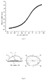
- the relation curve between the emergent angle ⁇ 2 and the incident angle ⁇ is as shown in Fig. 5 .
- the coordinate value of each point (X,Y) on the Y-Y section profile line of the light-distribution free curved surface 12 can be calculated by use of the prior art and according to the light distribution condition; to increase the speed, computer programming can be adopted. The higher the value of ⁇ is, the higher the precision of the fitted curve is and the better the light distribution effect is.
- the incident concave surface 11 of the present invention is of a goose-egg-shaped structure as a whole, and the view of the incident concave surface 11 in the Y-Y section and the bottom surface is as shown in Fig. 6 .
- the line segment A-B-C of the incident concave surface 11 in the contour line of the Y-Y section is a segment of inclined elliptical arc with the long axis of OC and the short axis of OB; the value of OC is 1-1.5 times the diameter of the COB module LED area light source; the ratio OC/OB of the long axis to the short axis is between 1.2-2.5, preferably 1.6 herein.
- the short axis OB has an inclination angle and the included angle between the short axis OB and the optical axis OZ is ⁇ of which the numerical area can be between 15 and 20 degrees; preferably in the invention, the inclination angle ⁇ is 17.5 degrees.
- the line segment CD is a segment of arc centered on the point O, and is tangent with the inclined elliptical arc A-B-C at the point C.
- the diagonal lines OL and OF, on a side close to A, of the incident concave surface 11 are longer, while the diagonal lines OJ and OH, on a side close to D, of the same are shorter, and the ratio OL/OJ ranges from 1.1 to 1.3, preferably 1.2.
- the light distribution principle of the secondary optical lens of the present invention in the X-X section is as shown in Fig. 7 .
- All the light rays emitted from the center point O of the COB module LED light-emitting surface are refracted by the concave surface 11 and then distributed through the free light-distribution curve 12 arranged above, and the emergent rays after light distribution are distributed within a range of an included angle between - ⁇ and + ⁇ with the optical axis, wherein ⁇ is greater than or equal to 60 degrees and less than or equal to 75 degrees, preferably 70 degrees.
- Light distribution of the secondary optical lens of the present invention to one single light ray in the X-X section is as shown in Fig. 8 .
- the light ray OU emitted from the center point O of the COB module LED is incident into the concave surface 11; the refracted light UV is distributed through the light-distribution free curved surface 12 arranged above, and is emergent as the emergent ray VW after light distribution.
- the positive and negative signs of the light angles are defined as the same herein: the light ray deflecting toward the left of the optical axis OZ is negative, while the light ray deflecting toward the right of the optical axis OZ is positive.
- the relation curve between the light distribution angle ⁇ 1 and the incident angle ⁇ is as shown in Fig. 9 .
- the coordinate value of each point (X,Y) on the X-X section profile line of the light-distribution free curved surface 12 can be calculated according to the above light distribution condition, based on computer programming and by use of a mathematical iterative method.
- the fitted section line of the curved surface 12 as shown in Fig. 4 and the section line of the incident surface 11 as shown in Fig. 4 are scanned on the fitted curves as shown in Fig. 8 , and then the desired incident concave surface 11 and the light-distribution free curved surface 12 can be established; the formed light spots are also substantially square.
- Fig. 10 shows the ray tracing of a specific embodiment of the secondary optical lens of the present invention. It can be seen that the beam divergence angle of the lens in the X-X direction (as shown in the left figure) is very large, but in the Y-Y direction (as shown in the right figure), the light of the lens is projected slantwise at a large angle. Fig.
- Fig. 11 shows the light spot shape and the illumination distribution of the specific embodiment of the secondary optical lens of the present invention at the distance of 10m; a spot diagram is in asymmetrical distribution and the center of each spot is not in the intersection position of spider lines.
- Fig. 12 shows the light distribution curve of the specific embodiment of the secondary optical lens of the present invention. It can be seen that the light distribution curve is in batwing distribution in the X-X direction with the beam angle of +/-70.4451648489361450 degrees (the full beam angle is about 140 degrees), and in the Y-Y direction, the light distribution curve has a very large deflection angle and deviates from the axis by about 68 degrees at the position of the maximum peak intensity; as a result, an anticipatory goal is achieved.
Landscapes
- Engineering & Computer Science (AREA)
- General Engineering & Computer Science (AREA)
- Non-Portable Lighting Devices Or Systems Thereof (AREA)
- Led Device Packages (AREA)
Abstract
Description
- The present invention relates to a lighting technology, in particular relates to a method and a device capable of realizing road illumination to at least 6 lanes and at an interval of less than 45m through one single light source or high-pole lamp illumination by virtue of a light distribution technology, and specifically relates to a method and a device for greatly increasing the irradiation range of a lamp.
- At present, as the required illumination distance is at least 75m and a light-distribution deflection angle of an optical lens or a reflecting cup is insufficient, the existing LED high-pole lamps for plaza illumination are often mounted at a large elevation angle so that light can be projected onto the ground on the opposite side of a lamp pole, whereby lots of light rays are directly projected to the sky to cause light pollution. As the high-pole lamps for plaza illuminations are all high in power and a large number of lamps are required to be circumferentially mounted on one lamp pole by 360 degrees, strong glare is generated by the lamps and directly emitted to the sky to produce adverse effects on airplanes flying at high altitudes (pilots may erroneously identify it as navigation lights); besides, the strong light emitted to the sky illuminates the clouds and the formed noisy background light covers the starlight, so that the primary color of the night sky is changed, and therefore, the quiet atmosphere of the night is weakened.
- In addition, secondary optical lenses of the existing LED street lamps for road illumination are substantially designed according to the requirement of 2-5 lanes. In a direction vertical to the road, the own deflection angles of the optical lenses are substantially within the range of 30 to 50 degrees. Due to the insufficient deflection angles, the light produced by the optical lenses cannot reach so far as 6-7 lanes and fails in meeting the road illumination requirement of 6-7 lanes.
- The present invention is to invent a method and a device for greatly increasing the irradiation range of a lamp, aiming at the problem that the existing LED illuminating street lamps are incapable of satisfying the illumination of street lamps on one single side to more than 6 lanes or plaza illumination due to unreasonable design of the secondary optical lenses.
- One of the technical solutions of the present invention is as follows:
- A method for greatly increasing an irradiation range of a street lamp or a high-pole lamp is characterized as follows:
- firstly, a COB module LED area light source is adopted as a light source;
- secondly, the LED area light source is put into an incident concave surface to be covered by the same, so that the LED point light source is primarily refracted by the incident concave surface;
- thirdly, a light-distribution free curved surface is further arranged to cover the incident concave surface, so that the light ray primarily refracted by the incident concave surface is subsequently refracted by the light-distribution free curved surface to deflect by a large angle; after two refractions, an included angle between a position, perpendicular to an extension direction of a road, of the peak intensity and an optical axis ranges from 60 to 75 degrees and a light distribution angle in a direction in accordance with the extension direction of the road ranges from 120 to 150 degrees, whereby the illumination of one single COB module LED point light source to at least 6 lanes and illumination at an interval of at least 35m or long-distance illumination of a high-pole lamp are realized;

- wherein θ2 represents an included angle between an emergent ray and an optical axis OZ when the included angle between an incident ray OP and the optical axis OZ is α; OP represents the light ray OP emitted from the center point O of the COB module LED and incident into the incident concave surface (11); OZ represents an axis passing the center point O of the COB module LED and perpendicular to a mounting bottom surface thereof; a refracted ray PQ passes the light-distribution free curved surface (12) for light distribution and is emergent as a light ray QS after light distribution;
- -ξ1 and ξ2 represent the maximum deflection angles expected to be obtained at the maximum light distribution angle of a marginal ray when the incident angle α is -90 degrees and +90 degrees, and the absolute values of the maximum deflection angles range from 60 to 75 degrees; the light distribution angle θ2 of the deflected emergent ray QS falls into a range of -ξ1 to ξ2; the positive and negative signs of the angles are herein defined as follows: a light ray deflecting toward the left of the optical axis OZ is negative, while a light ray deflecting toward the right of the optical axis OZ is positive; the numerical area of α ranges from -ξ1 to ξ2;

- The diameter of the COB module LED area light source is smaller than 30mm.
- The other one of the technical solutions of the present invention is as follows:
- A street lamp lens or a high-pole lamp lens capable of greatly increasing the irradiation range of a street lamp, comprising a COB module LED light source, wherein the COB module LED light source is covered with a primary incident concave lens which is covered with a light-distribution curved lens; in a direction (Y-Y) perpendicular to a road, an included angle between a direction of a deflection angle of a light distribution curve of the light-distribution curved lens in a position of the peak intensity, and an optical axis ranges from 60 to 75 degrees, and in a direction (X-X) along the road, a light distribution angle of the light-distribution curved lens ranges from 120 to 150 degrees; the coordinate value of each point (x,y) on a section profile line, extending in the direction perpendicular to the extension direction of the road and passing the COB module LED point light source, of the light-distribution curved lens is determined by the following light distribution condition of one single light ray:

- wherein θ2 represents an included angle between an emergent ray and an optical axis OZ when the included angle between an incident ray OP and the optical axis OZ is α; OP represents the light ray OP emitted from the center point O of the COB module LED and incident into an incident concave surface (11); OZ represents an axis passing the center point O of the COB module LED and perpendicular to a mounting bottom surface thereof; a refracted ray PQ passes a light-distribution free curved surface (12) for light distribution and is emergent as a light ray QS after light distribution;
- -ξ1 and ξ2 represent the maximum deflection angles expected to be obtained at the maximum light distribution angle of a marginal ray when the incident angle α is -90 degrees and +90 degrees, and the absolute values of the maximum deflection angles range from 60 to 75 degrees; the light distribution angle θ2 of the deflected emergent ray QS falls into a range of -ξ1 to ξ2; the positive and negative signs of the angles are herein defined as follows: a light ray deflecting toward the left of the optical axis OZ is negative, while a light ray deflecting toward the right of the optical axis OZ is positive; the numerical area of α ranges from -ξ1 to ξ2;
the primary incident concave lens and the light-distribution curved lens are formed by scanning the sectional curve along a curve determined according to the following condition:
- wherein ψ represents the maximum light distribution angle of the edge ray required when the incident angle β of the incident concave surface (11) is +/-90 degrees; the light distribution angle θ1 falls into a range from the included angle of the optical axis and +/-ψ; the positive and negative signs of the light angles are defined as the same herein: the light ray deflecting toward the left of the optical axis OZ is negative, while the light ray deflecting toward the right of the optical axis OZ is positive.
- 4. The street lamp lens or the high-pole lamp lens capable of greatly increasing the irradiation range of the street lamp of claim 1, wherein the light-distribution free curved surface (12) is 102.2092285mm in width and 50.8887939mm in height, and the errors of all the dimensions are +/-1mm.
- The present invention has the following beneficial effects:
- It is realized in the present invention that the light distribution curve of the lens in the direction (Y-Y) vertical to the road has a very large deflection angle and the included angle between the position of the peak intensity of the lens and the optical axis ranges from 60 to 75 degrees; when the lens is mounted on a high-pole lamp with a height of 20m, it is capable of uniformly illuminating the ground above a range of 40-50m. In the direction (X-X) along the road, the light distribution curve of the lens is in a batwing shape and its light distribution angle ranges from 120 to 150 degrees; hence, it is capable of illuminating by the width of 6-7 lanes, and also capable of meeting the requirement of road illumination at an interval of 35m between the lamp poles along the road; as a result, therefore the lens is applicable to road illumination of 6-7 lanes.
-
-
Fig. 1 is a structural schematic diagram of the present invention. -
Fig. 2 is a sectional drawing of the street lamp as shown inFig. 1 in the Y-Y direction and the X-X direction. -
Fig. 3 is a schematic diagram of a light distribution principle of the street lamp as shown inFig. 1 in the Y-Y section. -
Fig. 4 is a schematic diagram of light distribution of the street lamp as shown inFig. 1 to one single light ray in the Y-Y section. -
Fig. 5 is a schematic diagram of a relation curve between an emergent angle θ2 and an incident angle α during light distribution of the street lamp as shown inFig. 1 to one single light ray in the Y-Y direction. -
Fig. 6 shows a sectional drawing and a bottom view of the incidentconcave surface 11 of the present invention in the Y-Y direction. -
Fig. 7 is a schematic diagram of a section of the street lamp as shown inFig. 1 in the X-X direction and a light distribution principle. -
Fig. 8 is a schematic diagram of light distribution of one single light ray inFig. 7 . -
Fig. 9 is a schematic diagram of a relation curve between an emergent angle θ1 and an incident angle β during light distribution of the one single light ray as shown inFig. 8 . -
Fig. 10 is a schematic diagram of ray tracing of the street lamp of the present invention. -
Fig. 11 is a schematic diagram of a light spot shape at a distance of 10m and illumination distribution of the street lamp as shown inFig. 1 . -
Fig. 12 is a schematic diagram of the light distribution curve (the far-end angle distribution of the light intensity) of the present invention. - The present invention is further described below by combining the accompanying drawings and embodiments.
- The structural schematic diagram of the double lens with secondary light distribution of the present invention is as shown in
Fig. 1 . It is composed of the bottom goose-egg-shaped incidentconcave surface 11, the light-distribution freecurved surface 12 arranged above, abottom plane 13, and asquare platform 14 for mounting. Its sectional drawing in the Y-Y direction and the X-X direction is as shown inFig. 2 . The incidentconcave surface 11 is deeper on one side and shallower on the other side, while the light-distribution freecurved surface 12 is relatively inclined on one side in a direction opposite to the incident concave surface and relatively convex on the other side. The optical axis OZ passes the center of a COB module LED light-emitting surface and is vertical to the COB module LED light-emitting surface, and deviates toward the relatively inclined side of the light-distribution freecurved surface 12. The so-called COB module LED represents Chips on board in English, namely, an integrated light source with a lot of chips integrated on the same printed circuit board; the diameter of the light-emitting surface is within ϕ30mm, and preferably, the diameter of the light-emitting surface is ϕ28mm herein. The size of thesquare platform 14 for mounting is not limited, and preferably, the length and width are 112mm*117mm and each of the four corners is provided with an R30mm chamfer herein. The light-distribution freecurved surface 12 is as shown inFig. 1 , which is less than 120mm in length and width and less than 55mm in height. Preferably, the light-distribution freecurved surface 12 is 102.2092285mm in width and 50.8887939mm in height, and the errors of all the dimensions are +/-1mm. - The light distribution principle of the secondary optical lens of the present invention in the Y-Y section is as shown in
Fig. 3 . All the light rays emitted from the center point O of the COB module LED light-emitting surface is refracted by theconcave surface 11 and distributed through the free light-distribution curve 12 arranged above, and the emergent rays after light distribution are distributed within a range of an included angle between -ξ1 and ξ2 with the optical axis, wherein -ξ1 is greater than or equal to -75 degrees and less than or equal to -65 degrees, while ξ2 is greater than or equal to 55 degrees and less than or equal to 65 degrees; preferably in the embodiment, -ξ1 is -72.5 degrees, while ξ2 is 62.5 degrees. - Light distribution of the secondary optical lens of the present invention to one single light ray in the Y-Y section is as shown in
Fig. 4 . The light ray OP emitted from the center point O of the COB module LED is incident into theconcave surface 11; the refracted ray PQ is distributed through the light-distribution freecurved surface 12 arranged above, and emergent as the light ray QS after light distribution. Assumed that the included angle between the incident ray OP and the optical axis OZ is α and the included angle between the emergent ray and the optical axis OZ is θ2, the emergent angle θ2 and the incident angle α satisfy the following light distribution condition:
Fig. 5 . The coordinate value of each point (X,Y) on the Y-Y section profile line of the light-distribution freecurved surface 12 can be calculated by use of the prior art and according to the light distribution condition; to increase the speed, computer programming can be adopted. The higher the value of α is, the higher the precision of the fitted curve is and the better the light distribution effect is. - It can be seen from
Fig. 1 andFig. 6 that the incidentconcave surface 11 of the present invention is of a goose-egg-shaped structure as a whole, and the view of the incidentconcave surface 11 in the Y-Y section and the bottom surface is as shown inFig. 6 . The line segment A-B-C of the incidentconcave surface 11 in the contour line of the Y-Y section is a segment of inclined elliptical arc with the long axis of OC and the short axis of OB; the value of OC is 1-1.5 times the diameter of the COB module LED area light source; the ratio OC/OB of the long axis to the short axis is between 1.2-2.5, preferably 1.6 herein. The short axis OB has an inclination angle and the included angle between the short axis OB and the optical axis OZ is τ of which the numerical area can be between 15 and 20 degrees; preferably in the invention, the inclination angle τ is 17.5 degrees. The line segment CD is a segment of arc centered on the point O, and is tangent with the inclined elliptical arc A-B-C at the point C. In a bottom view on the right side ofFig. 6 , the diagonal lines OL and OF, on a side close to A, of the incidentconcave surface 11 are longer, while the diagonal lines OJ and OH, on a side close to D, of the same are shorter, and the ratio OL/OJ ranges from 1.1 to 1.3, preferably 1.2. - The light distribution principle of the secondary optical lens of the present invention in the X-X section is as shown in
Fig. 7 . All the light rays emitted from the center point O of the COB module LED light-emitting surface are refracted by theconcave surface 11 and then distributed through the free light-distribution curve 12 arranged above, and the emergent rays after light distribution are distributed within a range of an included angle between -ψ and +ψ with the optical axis, wherein ψ is greater than or equal to 60 degrees and less than or equal to 75 degrees, preferably 70 degrees. - Light distribution of the secondary optical lens of the present invention to one single light ray in the X-X section is as shown in
Fig. 8 . The light ray OU emitted from the center point O of the COB module LED is incident into theconcave surface 11; the refracted light UV is distributed through the light-distribution freecurved surface 12 arranged above, and is emergent as the emergent ray VW after light distribution. Assumed that the included angle between the incident ray OU and the optical axis OZ is β and the included angle between the emergent ray VW and the optical axis OZ is θ1, the emergent angle θ1 and the incident angle β satisfy the following light distribution condition:
formula 2, ψ represents the maximum light distribution angle of the edge ray required when the incident angle β is +/-90 degrees as shown inFig. 7 , and ψ is preferably 70 degrees in the present invention; the light distribution angle θ1 of the emergent ray VW after light distribution falls into a range of an included angle between -ψ and +ψ with the optical axis. The positive and negative signs of the light angles are defined as the same herein: the light ray deflecting toward the left of the optical axis OZ is negative, while the light ray deflecting toward the right of the optical axis OZ is positive. According toformula 2, the relation curve between the light distribution angle θ1 and the incident angle β is as shown inFig. 9 . The coordinate value of each point (X,Y) on the X-X section profile line of the light-distribution freecurved surface 12 can be calculated according to the above light distribution condition, based on computer programming and by use of a mathematical iterative method. The higher the value of β is, the higher the precision of the fitted section curve of thecurved surface 12 as shown inFig. 7 is. It can be seen fromFigs. 7 and 8 that the section curve of thecurved surface 11 is an arc line of which the diameter is equal to OC. - The fitted section line of the
curved surface 12 as shown inFig. 4 and the section line of theincident surface 11 as shown inFig. 4 are scanned on the fitted curves as shown inFig. 8 , and then the desired incidentconcave surface 11 and the light-distribution freecurved surface 12 can be established; the formed light spots are also substantially square. - Computer simulation and photometric analysis of the secondary optical lens of the present invention are described below under the following assumptions: the COB module LED is 250W with the luminous flux of 25000 lumens, the size of the light-emitting surface is ϕ28mm, the elevation angle of the lens is 0 degree and the screen is placed at the distance of 10m.
Fig. 10 shows the ray tracing of a specific embodiment of the secondary optical lens of the present invention. It can be seen that the beam divergence angle of the lens in the X-X direction (as shown in the left figure) is very large, but in the Y-Y direction (as shown in the right figure), the light of the lens is projected slantwise at a large angle.Fig. 11 shows the light spot shape and the illumination distribution of the specific embodiment of the secondary optical lens of the present invention at the distance of 10m; a spot diagram is in asymmetrical distribution and the center of each spot is not in the intersection position of spider lines.Fig. 12 shows the light distribution curve of the specific embodiment of the secondary optical lens of the present invention. It can be seen that the light distribution curve is in batwing distribution in the X-X direction with the beam angle of +/-70.4451648489361450 degrees (the full beam angle is about 140 degrees), and in the Y-Y direction, the light distribution curve has a very large deflection angle and deviates from the axis by about 68 degrees at the position of the maximum peak intensity; as a result, an anticipatory goal is achieved. - Parts not involved in the present invention all are the same as the prior art or can be implemented by use of the prior art.
Claims (4)
- A method for greatly increasing the irradiation range of a street lamp or a high-pole lamp, wherein firstly, a COB module LED area light source is adopted as a light source; secondly, the LED area light source is firstly put into an incident concave surface (11) to be covered by the same, so that the LED point light source is primarily refracted by the incident concave surface (11); thirdly, a light-distribution free curved surface (12) is further arranged to cover the incident concave surface (11), so that the light ray primarily refracted by the incident concave surface (11) is subsequently refracted by the light-distribution free curved surface (12) to deflect by a large angle; after two refractions, an included angle between a position, perpendicular to an extension direction of a road, of the peak intensity and an optical axis ranges from 60 to 75 degrees and a light distribution angle in a direction in accordance with the extension direction of the road ranges from 120 to 150 degrees, whereby the illumination of one single COB module LED point light source to at least 6 lanes and illumination at an interval of at least 35m or long-distance illumination of a high-pole lamp are realized; the coordinate value of each point (x,y) on a section profile line, extending in the direction perpendicular to the extension direction of the road and passing the COB module LED point light source, of the light-distribution free curved surface (12) is determined by the following light distribution condition of one single light ray:


- The method of claim 1, wherein the diameter of the COB module LED area light source is smaller than 30mm.
- A street lamp lens or a high-pole lamp lens capable of greatly increasing the irradiation range of a street lamp, comprising a COB module LED light source, wherein the COB module LED light source is covered with a primary incident concave lens which is covered with a light-distribution curved lens; in a direction (Y-Y) perpendicular to a road, an included angle between a direction of a deflection angle of a light distribution curve of the light-distribution curved lens in a position of the peak intensity, and an optical axis ranges from 60 to 75 degrees, and in a direction (X-X) along the road, a light distribution angle of the light-distribution curved lens ranges from 120 to 150 degrees; the coordinate value of each point (x,y) on a section profile line, extending in the direction perpendicular to the extension direction of the road and passing the COB module LED point light source, of the light-distribution curved lens is determined by the following light distribution condition of one single light ray:


- The street lamp lens or the high-pole lamp lens capable of greatly increasing the irradiation range of the street lamp of claim 1, wherein the light-distribution free curved surface (12) is 102.2092285mm in width and 50.8887939mm in height, and the errors of all the dimensions are +/-1mm
Applications Claiming Priority (2)
| Application Number | Priority Date | Filing Date | Title |
|---|---|---|---|
| CN201310690220.7A CN103644532B (en) | 2013-12-16 | 2013-12-16 | Increase substantially method and the device of Street Light Illumination scope |
| PCT/CN2014/092328 WO2015090134A1 (en) | 2013-12-16 | 2014-11-27 | Method and device for greatly increasing irradiation range of street lamp |
Publications (3)
| Publication Number | Publication Date |
|---|---|
| EP3093558A1 true EP3093558A1 (en) | 2016-11-16 |
| EP3093558A4 EP3093558A4 (en) | 2017-08-02 |
| EP3093558B1 EP3093558B1 (en) | 2018-02-21 |
Family
ID=50249788
Family Applications (1)
| Application Number | Title | Priority Date | Filing Date |
|---|---|---|---|
| EP14872591.4A Not-in-force EP3093558B1 (en) | 2013-12-16 | 2014-11-27 | Method and device for greatly increasing irradiation range of street lamp |
Country Status (6)
| Country | Link |
|---|---|
| US (1) | US9784429B2 (en) |
| EP (1) | EP3093558B1 (en) |
| CN (1) | CN103644532B (en) |
| AU (1) | AU2014366126B2 (en) |
| CA (1) | CA2924790C (en) |
| WO (1) | WO2015090134A1 (en) |
Cited By (1)
| Publication number | Priority date | Publication date | Assignee | Title |
|---|---|---|---|---|
| TWI684803B (en) * | 2019-08-16 | 2020-02-11 | 賀喜能源股份有限公司 | Lens, light emitting element, and street light |
Families Citing this family (15)
| Publication number | Priority date | Publication date | Assignee | Title |
|---|---|---|---|---|
| CN103644532B (en) * | 2013-12-16 | 2015-08-26 | 宏力照明集团有限公司 | Increase substantially method and the device of Street Light Illumination scope |
| CN103982802B (en) * | 2014-05-28 | 2017-06-06 | 深圳市九洲光电科技有限公司 | A kind of LED blackboard lightses |
| US10032969B2 (en) | 2014-12-26 | 2018-07-24 | Nichia Corporation | Light emitting device |
| CN104534405B (en) * | 2014-12-31 | 2017-07-21 | 东莞市汉龙礼品有限公司 | LED lens |
| CN105020678B (en) * | 2015-08-04 | 2017-10-13 | 珠海金晟照明科技有限公司 | Lens unit, lens subassembly and road lamp cap |
| CN107036021A (en) * | 2017-06-07 | 2017-08-11 | 成都恒坤光电科技有限公司 | A kind of multiple light courcess high beam |
| CN109268735B (en) * | 2018-09-10 | 2021-09-07 | 广东工业大学 | A kind of fishery auxiliary lighting device |
| US10677419B1 (en) | 2019-05-01 | 2020-06-09 | Lumileds Holding B.V. | Selectively frosted optical element for beam shaping |
| CN111765435B (en) * | 2020-07-14 | 2022-05-06 | 广东视康照明科技有限公司 | Method for improving vertical illumination uniformity of blackboard lamp |
| CN113339755B (en) * | 2021-06-05 | 2022-12-27 | 长春希达电子技术有限公司 | Integrated large-space lighting optical device and installation method thereof |
| CN114562706B (en) * | 2022-04-08 | 2024-04-05 | 杭州罗莱迪思科技股份有限公司 | Anti-dazzle low-level street lamp lens integrally molded and application thereof |
| CN115325470B (en) * | 2022-08-08 | 2023-06-16 | 重庆绿色科技开发(集团)有限公司 | Manufacturing five-primary-color full-spectrum multi-color temperature light source by red, green, blue, yellow and white LED light mixing technology |
| CN115307110A (en) * | 2022-08-18 | 2022-11-08 | 杭州星野光学科技有限公司 | Anti-dazzle high-uniformity lens group for LED and LED lamp |
| KR102578782B1 (en) * | 2022-11-17 | 2023-09-20 | 주식회사 마루라이팅 | Lens for lighting apparatus and lighting apparatus including same |
| WO2025043755A1 (en) * | 2023-09-02 | 2025-03-06 | 叶月连 | Large-plate glass lens |
Family Cites Families (15)
| Publication number | Priority date | Publication date | Assignee | Title |
|---|---|---|---|---|
| JP5213383B2 (en) * | 2007-08-09 | 2013-06-19 | シャープ株式会社 | LIGHT EMITTING DEVICE AND LIGHTING DEVICE EQUIPPED WITH THE SAME |
| TW201007082A (en) * | 2008-08-08 | 2010-02-16 | Genius Electronic Optical Co Ltd | Optical lens of polarizing illumination |
| CN101660705A (en) * | 2008-08-27 | 2010-03-03 | 玉晶光电股份有限公司 | Optical lens body for polarized light illumination |
| TW201109585A (en) * | 2009-09-04 | 2011-03-16 | Genius Electronic Optical Co Ltd | Optical lens |
| TW201200798A (en) * | 2010-06-25 | 2012-01-01 | Alliance Optotek Co Ltd | Optic element of lighting device and design method thereof |
| CN101915391A (en) * | 2010-08-10 | 2010-12-15 | 深圳万润科技股份有限公司 | Polarization LED light distribution lens and LED street lamp |
| JP2012186019A (en) * | 2011-03-04 | 2012-09-27 | Sharp Corp | Lighting device and, lighting fixture equipped with lighting device |
| WO2013094599A1 (en) * | 2011-12-20 | 2013-06-27 | ナルックス株式会社 | Optical element, illumination device including optical element and illumination module using illumination device |
| CN103307548B (en) * | 2012-03-09 | 2018-08-10 | 欧司朗股份有限公司 | Lens and lighting device with the lens |
| CN103375769A (en) * | 2012-12-25 | 2013-10-30 | 深圳市斯派克光电科技有限公司 | Polarized lens unit and lens module for LED streetlights |
| CN203147627U (en) * | 2012-12-25 | 2013-08-21 | 深圳市斯派克光电科技有限公司 | Polarized light lens unit and polarized light lens module for LED street lamp |
| CN203323002U (en) * | 2013-07-26 | 2013-12-04 | 苏州东山精密制造股份有限公司 | LED street lamp lens and LED street lamp system |
| CN103644532B (en) | 2013-12-16 | 2015-08-26 | 宏力照明集团有限公司 | Increase substantially method and the device of Street Light Illumination scope |
| CN203797558U (en) * | 2013-12-16 | 2014-08-27 | 宏力照明集团有限公司 | Streetlamp lens or high-pole lamp lens capable of greatly widening irradiation range of streetlamp |
| CN103807806B (en) * | 2014-01-22 | 2016-01-20 | 宏力照明集团有限公司 | The light distributing method of the COB module LED street lamp lens in 3,5 tracks can be irradiated to |
-
2013
- 2013-12-16 CN CN201310690220.7A patent/CN103644532B/en active Active
-
2014
- 2014-11-27 CA CA2924790A patent/CA2924790C/en active Active
- 2014-11-27 WO PCT/CN2014/092328 patent/WO2015090134A1/en active Application Filing
- 2014-11-27 US US14/913,405 patent/US9784429B2/en active Active
- 2014-11-27 EP EP14872591.4A patent/EP3093558B1/en not_active Not-in-force
- 2014-11-27 AU AU2014366126A patent/AU2014366126B2/en not_active Ceased
Cited By (1)
| Publication number | Priority date | Publication date | Assignee | Title |
|---|---|---|---|---|
| TWI684803B (en) * | 2019-08-16 | 2020-02-11 | 賀喜能源股份有限公司 | Lens, light emitting element, and street light |
Also Published As
| Publication number | Publication date |
|---|---|
| US20170254505A1 (en) | 2017-09-07 |
| AU2014366126B2 (en) | 2016-07-28 |
| CN103644532B (en) | 2015-08-26 |
| US9784429B2 (en) | 2017-10-10 |
| CA2924790A1 (en) | 2015-06-25 |
| EP3093558B1 (en) | 2018-02-21 |
| AU2014366126A1 (en) | 2016-03-10 |
| WO2015090134A1 (en) | 2015-06-25 |
| CN103644532A (en) | 2014-03-19 |
| CA2924790C (en) | 2018-02-27 |
| EP3093558A4 (en) | 2017-08-02 |
Similar Documents
| Publication | Publication Date | Title |
|---|---|---|
| EP3093558B1 (en) | Method and device for greatly increasing irradiation range of street lamp | |
| US8434912B2 (en) | LED device for wide beam generation | |
| US8414161B2 (en) | LED device for wide beam generation | |
| CN203797558U (en) | Streetlamp lens or high-pole lamp lens capable of greatly widening irradiation range of streetlamp | |
| US10895364B2 (en) | Energy reduction optics | |
| EP2802920A1 (en) | Improved optical systems and led luminaires | |
| CN210107217U (en) | Cut-off type low street lamp | |
| CN110274192A (en) | Light chopping low level street lamp and preparation method thereof | |
| CN105953175B (en) | Projecting lamp lens, have light-emitting module and projecting lamp of this projecting lamp lens | |
| AU2012268832B2 (en) | An improved led device for wide beam generation | |
| CN107940258A (en) | A kind of light high density line reflection LED lamp |
Legal Events
| Date | Code | Title | Description |
|---|---|---|---|
| PUAI | Public reference made under article 153(3) epc to a published international application that has entered the european phase |
Free format text: ORIGINAL CODE: 0009012 |
|
| 17P | Request for examination filed |
Effective date: 20160212 |
|
| AK | Designated contracting states |
Kind code of ref document: A1 Designated state(s): AL AT BE BG CH CY CZ DE DK EE ES FI FR GB GR HR HU IE IS IT LI LT LU LV MC MK MT NL NO PL PT RO RS SE SI SK SM TR |
|
| AX | Request for extension of the european patent |
Extension state: BA ME |
|
| DAX | Request for extension of the european patent (deleted) | ||
| A4 | Supplementary search report drawn up and despatched |
Effective date: 20170630 |
|
| RIC1 | Information provided on ipc code assigned before grant |
Ipc: F21Y 115/10 20160101ALN20170626BHEP Ipc: F21V 5/04 20060101AFI20170626BHEP Ipc: F21S 8/08 20060101ALI20170626BHEP Ipc: F21Y 101/00 20160101ALI20170626BHEP Ipc: F21W 131/103 20060101ALI20170626BHEP |
|
| RIC1 | Information provided on ipc code assigned before grant |
Ipc: F21V 5/04 20060101AFI20170907BHEP Ipc: F21W 131/103 20060101ALI20170907BHEP Ipc: F21Y 101/00 20160101ALI20170907BHEP Ipc: F21Y 115/10 20160101ALN20170907BHEP Ipc: F21S 8/08 20060101ALI20170907BHEP |
|
| RIC1 | Information provided on ipc code assigned before grant |
Ipc: F21Y 101/00 20160101ALI20170914BHEP Ipc: F21Y 115/10 20160101ALN20170914BHEP Ipc: F21V 5/04 20060101AFI20170914BHEP Ipc: F21W 131/103 20060101ALI20170914BHEP Ipc: F21S 8/08 20060101ALI20170914BHEP |
|
| GRAP | Despatch of communication of intention to grant a patent |
Free format text: ORIGINAL CODE: EPIDOSNIGR1 |
|
| STAA | Information on the status of an ep patent application or granted ep patent |
Free format text: STATUS: GRANT OF PATENT IS INTENDED |
|
| INTG | Intention to grant announced |
Effective date: 20171020 |
|
| GRAS | Grant fee paid |
Free format text: ORIGINAL CODE: EPIDOSNIGR3 |
|
| GRAA | (expected) grant |
Free format text: ORIGINAL CODE: 0009210 |
|
| STAA | Information on the status of an ep patent application or granted ep patent |
Free format text: STATUS: THE PATENT HAS BEEN GRANTED |
|
| GRAT | Correction requested after decision to grant or after decision to maintain patent in amended form |
Free format text: ORIGINAL CODE: EPIDOSNCDEC |
|
| AK | Designated contracting states |
Kind code of ref document: B1 Designated state(s): AL AT BE BG CH CY CZ DE DK EE ES FI FR GB GR HR HU IE IS IT LI LT LU LV MC MK MT NL NO PL PT RO RS SE SI SK SM TR |
|
| REG | Reference to a national code |
Ref country code: GB Ref legal event code: FG4D |
|
| REG | Reference to a national code |
Ref country code: CH Ref legal event code: EP |
|
| REG | Reference to a national code |
Ref country code: AT Ref legal event code: REF Ref document number: 972146 Country of ref document: AT Kind code of ref document: T Effective date: 20180315 |
|
| REG | Reference to a national code |
Ref country code: IE Ref legal event code: FG4D |
|
| REG | Reference to a national code |
Ref country code: DE Ref legal event code: R096 Ref document number: 602014021481 Country of ref document: DE |
|
| REG | Reference to a national code |
Ref country code: NL Ref legal event code: MP Effective date: 20180221 |
|
| REG | Reference to a national code |
Ref country code: LT Ref legal event code: MG4D |
|
| REG | Reference to a national code |
Ref country code: AT Ref legal event code: MK05 Ref document number: 972146 Country of ref document: AT Kind code of ref document: T Effective date: 20180221 |
|
| PG25 | Lapsed in a contracting state [announced via postgrant information from national office to epo] |
Ref country code: HR Free format text: LAPSE BECAUSE OF FAILURE TO SUBMIT A TRANSLATION OF THE DESCRIPTION OR TO PAY THE FEE WITHIN THE PRESCRIBED TIME-LIMIT Effective date: 20180221 Ref country code: LT Free format text: LAPSE BECAUSE OF FAILURE TO SUBMIT A TRANSLATION OF THE DESCRIPTION OR TO PAY THE FEE WITHIN THE PRESCRIBED TIME-LIMIT Effective date: 20180221 Ref country code: CY Free format text: LAPSE BECAUSE OF FAILURE TO SUBMIT A TRANSLATION OF THE DESCRIPTION OR TO PAY THE FEE WITHIN THE PRESCRIBED TIME-LIMIT Effective date: 20180221 Ref country code: NL Free format text: LAPSE BECAUSE OF FAILURE TO SUBMIT A TRANSLATION OF THE DESCRIPTION OR TO PAY THE FEE WITHIN THE PRESCRIBED TIME-LIMIT Effective date: 20180221 Ref country code: NO Free format text: LAPSE BECAUSE OF FAILURE TO SUBMIT A TRANSLATION OF THE DESCRIPTION OR TO PAY THE FEE WITHIN THE PRESCRIBED TIME-LIMIT Effective date: 20180521 Ref country code: FI Free format text: LAPSE BECAUSE OF FAILURE TO SUBMIT A TRANSLATION OF THE DESCRIPTION OR TO PAY THE FEE WITHIN THE PRESCRIBED TIME-LIMIT Effective date: 20180221 Ref country code: ES Free format text: LAPSE BECAUSE OF FAILURE TO SUBMIT A TRANSLATION OF THE DESCRIPTION OR TO PAY THE FEE WITHIN THE PRESCRIBED TIME-LIMIT Effective date: 20180221 |
|
| PG25 | Lapsed in a contracting state [announced via postgrant information from national office to epo] |
Ref country code: RS Free format text: LAPSE BECAUSE OF FAILURE TO SUBMIT A TRANSLATION OF THE DESCRIPTION OR TO PAY THE FEE WITHIN THE PRESCRIBED TIME-LIMIT Effective date: 20180221 Ref country code: AT Free format text: LAPSE BECAUSE OF FAILURE TO SUBMIT A TRANSLATION OF THE DESCRIPTION OR TO PAY THE FEE WITHIN THE PRESCRIBED TIME-LIMIT Effective date: 20180221 Ref country code: LV Free format text: LAPSE BECAUSE OF FAILURE TO SUBMIT A TRANSLATION OF THE DESCRIPTION OR TO PAY THE FEE WITHIN THE PRESCRIBED TIME-LIMIT Effective date: 20180221 Ref country code: SE Free format text: LAPSE BECAUSE OF FAILURE TO SUBMIT A TRANSLATION OF THE DESCRIPTION OR TO PAY THE FEE WITHIN THE PRESCRIBED TIME-LIMIT Effective date: 20180221 Ref country code: BG Free format text: LAPSE BECAUSE OF FAILURE TO SUBMIT A TRANSLATION OF THE DESCRIPTION OR TO PAY THE FEE WITHIN THE PRESCRIBED TIME-LIMIT Effective date: 20180521 Ref country code: GR Free format text: LAPSE BECAUSE OF FAILURE TO SUBMIT A TRANSLATION OF THE DESCRIPTION OR TO PAY THE FEE WITHIN THE PRESCRIBED TIME-LIMIT Effective date: 20180522 |
|
| PG25 | Lapsed in a contracting state [announced via postgrant information from national office to epo] |
Ref country code: EE Free format text: LAPSE BECAUSE OF FAILURE TO SUBMIT A TRANSLATION OF THE DESCRIPTION OR TO PAY THE FEE WITHIN THE PRESCRIBED TIME-LIMIT Effective date: 20180221 Ref country code: RO Free format text: LAPSE BECAUSE OF FAILURE TO SUBMIT A TRANSLATION OF THE DESCRIPTION OR TO PAY THE FEE WITHIN THE PRESCRIBED TIME-LIMIT Effective date: 20180221 Ref country code: IT Free format text: LAPSE BECAUSE OF FAILURE TO SUBMIT A TRANSLATION OF THE DESCRIPTION OR TO PAY THE FEE WITHIN THE PRESCRIBED TIME-LIMIT Effective date: 20180221 Ref country code: PL Free format text: LAPSE BECAUSE OF FAILURE TO SUBMIT A TRANSLATION OF THE DESCRIPTION OR TO PAY THE FEE WITHIN THE PRESCRIBED TIME-LIMIT Effective date: 20180221 Ref country code: AL Free format text: LAPSE BECAUSE OF FAILURE TO SUBMIT A TRANSLATION OF THE DESCRIPTION OR TO PAY THE FEE WITHIN THE PRESCRIBED TIME-LIMIT Effective date: 20180221 |
|
| REG | Reference to a national code |
Ref country code: DE Ref legal event code: R097 Ref document number: 602014021481 Country of ref document: DE |
|
| PG25 | Lapsed in a contracting state [announced via postgrant information from national office to epo] |
Ref country code: SK Free format text: LAPSE BECAUSE OF FAILURE TO SUBMIT A TRANSLATION OF THE DESCRIPTION OR TO PAY THE FEE WITHIN THE PRESCRIBED TIME-LIMIT Effective date: 20180221 Ref country code: SM Free format text: LAPSE BECAUSE OF FAILURE TO SUBMIT A TRANSLATION OF THE DESCRIPTION OR TO PAY THE FEE WITHIN THE PRESCRIBED TIME-LIMIT Effective date: 20180221 Ref country code: DK Free format text: LAPSE BECAUSE OF FAILURE TO SUBMIT A TRANSLATION OF THE DESCRIPTION OR TO PAY THE FEE WITHIN THE PRESCRIBED TIME-LIMIT Effective date: 20180221 Ref country code: CZ Free format text: LAPSE BECAUSE OF FAILURE TO SUBMIT A TRANSLATION OF THE DESCRIPTION OR TO PAY THE FEE WITHIN THE PRESCRIBED TIME-LIMIT Effective date: 20180221 |
|
| PLBE | No opposition filed within time limit |
Free format text: ORIGINAL CODE: 0009261 |
|
| STAA | Information on the status of an ep patent application or granted ep patent |
Free format text: STATUS: NO OPPOSITION FILED WITHIN TIME LIMIT |
|
| 26N | No opposition filed |
Effective date: 20181122 |
|
| PG25 | Lapsed in a contracting state [announced via postgrant information from national office to epo] |
Ref country code: SI Free format text: LAPSE BECAUSE OF FAILURE TO SUBMIT A TRANSLATION OF THE DESCRIPTION OR TO PAY THE FEE WITHIN THE PRESCRIBED TIME-LIMIT Effective date: 20180221 |
|
| REG | Reference to a national code |
Ref country code: CH Ref legal event code: PL |
|
| GBPC | Gb: european patent ceased through non-payment of renewal fee |
Effective date: 20181127 |
|
| PG25 | Lapsed in a contracting state [announced via postgrant information from national office to epo] |
Ref country code: MC Free format text: LAPSE BECAUSE OF FAILURE TO SUBMIT A TRANSLATION OF THE DESCRIPTION OR TO PAY THE FEE WITHIN THE PRESCRIBED TIME-LIMIT Effective date: 20180221 Ref country code: LU Free format text: LAPSE BECAUSE OF NON-PAYMENT OF DUE FEES Effective date: 20181127 |
|
| REG | Reference to a national code |
Ref country code: BE Ref legal event code: MM Effective date: 20181130 |
|
| REG | Reference to a national code |
Ref country code: IE Ref legal event code: MM4A |
|
| PG25 | Lapsed in a contracting state [announced via postgrant information from national office to epo] |
Ref country code: CH Free format text: LAPSE BECAUSE OF NON-PAYMENT OF DUE FEES Effective date: 20181130 Ref country code: LI Free format text: LAPSE BECAUSE OF NON-PAYMENT OF DUE FEES Effective date: 20181130 |
|
| PG25 | Lapsed in a contracting state [announced via postgrant information from national office to epo] |
Ref country code: IE Free format text: LAPSE BECAUSE OF NON-PAYMENT OF DUE FEES Effective date: 20181127 |
|
| PG25 | Lapsed in a contracting state [announced via postgrant information from national office to epo] |
Ref country code: BE Free format text: LAPSE BECAUSE OF NON-PAYMENT OF DUE FEES Effective date: 20181130 |
|
| PG25 | Lapsed in a contracting state [announced via postgrant information from national office to epo] |
Ref country code: GB Free format text: LAPSE BECAUSE OF NON-PAYMENT OF DUE FEES Effective date: 20181127 |
|
| PG25 | Lapsed in a contracting state [announced via postgrant information from national office to epo] |
Ref country code: MT Free format text: LAPSE BECAUSE OF NON-PAYMENT OF DUE FEES Effective date: 20181127 |
|
| PG25 | Lapsed in a contracting state [announced via postgrant information from national office to epo] |
Ref country code: TR Free format text: LAPSE BECAUSE OF FAILURE TO SUBMIT A TRANSLATION OF THE DESCRIPTION OR TO PAY THE FEE WITHIN THE PRESCRIBED TIME-LIMIT Effective date: 20180221 |
|
| PG25 | Lapsed in a contracting state [announced via postgrant information from national office to epo] |
Ref country code: PT Free format text: LAPSE BECAUSE OF FAILURE TO SUBMIT A TRANSLATION OF THE DESCRIPTION OR TO PAY THE FEE WITHIN THE PRESCRIBED TIME-LIMIT Effective date: 20180221 |
|
| PG25 | Lapsed in a contracting state [announced via postgrant information from national office to epo] |
Ref country code: MK Free format text: LAPSE BECAUSE OF NON-PAYMENT OF DUE FEES Effective date: 20180221 Ref country code: HU Free format text: LAPSE BECAUSE OF FAILURE TO SUBMIT A TRANSLATION OF THE DESCRIPTION OR TO PAY THE FEE WITHIN THE PRESCRIBED TIME-LIMIT; INVALID AB INITIO Effective date: 20141127 |
|
| PG25 | Lapsed in a contracting state [announced via postgrant information from national office to epo] |
Ref country code: IS Free format text: LAPSE BECAUSE OF FAILURE TO SUBMIT A TRANSLATION OF THE DESCRIPTION OR TO PAY THE FEE WITHIN THE PRESCRIBED TIME-LIMIT Effective date: 20180621 |
|
| PGFP | Annual fee paid to national office [announced via postgrant information from national office to epo] |
Ref country code: DE Payment date: 20211215 Year of fee payment: 8 Ref country code: FR Payment date: 20211115 Year of fee payment: 8 |
|
| REG | Reference to a national code |
Ref country code: DE Ref legal event code: R119 Ref document number: 602014021481 Country of ref document: DE |
|
| PG25 | Lapsed in a contracting state [announced via postgrant information from national office to epo] |
Ref country code: DE Free format text: LAPSE BECAUSE OF NON-PAYMENT OF DUE FEES Effective date: 20230601 |
|
| PG25 | Lapsed in a contracting state [announced via postgrant information from national office to epo] |
Ref country code: FR Free format text: LAPSE BECAUSE OF NON-PAYMENT OF DUE FEES Effective date: 20221130 |