EP3061175B1 - Wireless power transmitter - Google Patents
Wireless power transmitter Download PDFInfo
- Publication number
- EP3061175B1 EP3061175B1 EP14852170.1A EP14852170A EP3061175B1 EP 3061175 B1 EP3061175 B1 EP 3061175B1 EP 14852170 A EP14852170 A EP 14852170A EP 3061175 B1 EP3061175 B1 EP 3061175B1
- Authority
- EP
- European Patent Office
- Prior art keywords
- wireless power
- wireless
- transmitting unit
- wireless transmitting
- power transmitter
- Prior art date
- Legal status (The legal status is an assumption and is not a legal conclusion. Google has not performed a legal analysis and makes no representation as to the accuracy of the status listed.)
- Active
Links
Images


Classifications
-
- H—ELECTRICITY
- H02—GENERATION; CONVERSION OR DISTRIBUTION OF ELECTRIC POWER
- H02J—CIRCUIT ARRANGEMENTS OR SYSTEMS FOR SUPPLYING OR DISTRIBUTING ELECTRIC POWER; SYSTEMS FOR STORING ELECTRIC ENERGY
- H02J50/00—Circuit arrangements or systems for wireless supply or distribution of electric power
- H02J50/40—Circuit arrangements or systems for wireless supply or distribution of electric power using two or more transmitting or receiving devices
- H02J50/402—Circuit arrangements or systems for wireless supply or distribution of electric power using two or more transmitting or receiving devices the two or more transmitting or the two or more receiving devices being integrated in the same unit, e.g. power mats with several coils or antennas with several sub-antennas
-
- H—ELECTRICITY
- H02—GENERATION; CONVERSION OR DISTRIBUTION OF ELECTRIC POWER
- H02J—CIRCUIT ARRANGEMENTS OR SYSTEMS FOR SUPPLYING OR DISTRIBUTING ELECTRIC POWER; SYSTEMS FOR STORING ELECTRIC ENERGY
- H02J50/00—Circuit arrangements or systems for wireless supply or distribution of electric power
- H02J50/005—Mechanical details of housing or structure aiming to accommodate the power transfer means, e.g. mechanical integration of coils, antennas or transducers into emitting or receiving devices
-
- H—ELECTRICITY
- H02—GENERATION; CONVERSION OR DISTRIBUTION OF ELECTRIC POWER
- H02J—CIRCUIT ARRANGEMENTS OR SYSTEMS FOR SUPPLYING OR DISTRIBUTING ELECTRIC POWER; SYSTEMS FOR STORING ELECTRIC ENERGY
- H02J50/00—Circuit arrangements or systems for wireless supply or distribution of electric power
- H02J50/10—Circuit arrangements or systems for wireless supply or distribution of electric power using inductive coupling
- H02J50/12—Circuit arrangements or systems for wireless supply or distribution of electric power using inductive coupling of the resonant type
-
- H02J7/70—
-
- H02J7/731—
-
- H—ELECTRICITY
- H04—ELECTRIC COMMUNICATION TECHNIQUE
- H04B—TRANSMISSION
- H04B5/00—Near-field transmission systems, e.g. inductive or capacitive transmission systems
- H04B5/70—Near-field transmission systems, e.g. inductive or capacitive transmission systems specially adapted for specific purposes
- H04B5/79—Near-field transmission systems, e.g. inductive or capacitive transmission systems specially adapted for specific purposes for data transfer in combination with power transfer
-
- H—ELECTRICITY
- H02—GENERATION; CONVERSION OR DISTRIBUTION OF ELECTRIC POWER
- H02J—CIRCUIT ARRANGEMENTS OR SYSTEMS FOR SUPPLYING OR DISTRIBUTING ELECTRIC POWER; SYSTEMS FOR STORING ELECTRIC ENERGY
- H02J50/00—Circuit arrangements or systems for wireless supply or distribution of electric power
- H02J50/20—Circuit arrangements or systems for wireless supply or distribution of electric power using microwaves or radio frequency waves
Definitions
- the embodiment relates to a wireless power charging system, and more particularly, to a wireless power transmitter for a wireless power charging system.
- various kinds of electronic appliances employ batteries and are driven by using the power charged in the batteries.
- the battery of an electron appliance may be exchanged or may be recharged.
- the electronic appliance may include a contact terminal for making contact with an external charging apparatus in order to charge the battery. That is, the electronic appliance is electrically connected to the charging apparatus through the contact terminal.
- the contact terminal may be exposed to an outside of the electronic appliance, so that the contact terminal may be contaminated or shot-circuited due to moisture. In this case, a contact error may be generated between the contact terminal and the charging apparatus, so that the battery of the electronic appliance may not be charged.
- the wireless power charging system includes a wireless power transmitter for wirelessly supplying power to an electronic appliance.
- the electronic appliance receives power according to a preset charging scheme.
- the wireless power transmitter in order to charge the electronic appliance, the wireless power transmitter must supply power to the electronic appliance in the same charging scheme as that of the electronic appliance. That is, when the wireless power transmitter is set in a charging scheme different from that of the electronic appliance, the wireless power transmitter does not charge the electronic appliance.
- WO2010/093723A1 proposes to use a plurality of coils in different spatial orientation to charge a plurality of different device inside a container like a bag or a toolbox.
- US2009/106567A1 shows a charging station with several charging coils of different size all being arranged in single plane on the front side and the backside of the charging station allowing for charging of different electronic devices.
- WO2011/091528A1 describes a charger with coil structures at the back and bottom sides of a groove shaped receptacle of an electronic device.
- the embodiment provides a wireless power transmitter for effectively charging an electronic appliance.
- a wireless power transmitter for charging a wireless power receiver which includes a first wireless transmitting unit disposed at a rear surface of the wireless power receiver and having a first charging scheme; and a second wireless transmitting unit disposed on at least one of side surfaces of the wireless power receiver and having a second charging scheme different from the first charging scheme.
- the wireless power transmitter further includes a control unit for transmitting power through the first wireless transmitting unit or the second wireless transmitting unit according to a charging scheme of the wireless power receiver.
- the second wireless transmitting unit is inclined from the first wireless power transmitter.
- the second wireless transmitting unit is perpendicular to the first wireless transmitting unit.
- a center of the second wireless transmitting unit is aligned on a same axis with a center of the wireless power receiver.
- the wireless power transmitter includes the first and second wireless power transmitting units and may charge the wireless power receiver in various charging schemes.
- the wireless power transmitter may more efficiently charge the wireless power receiver.
- the first and second wireless power transmitting units of the wireless power transmitter can be spaced apart from each other and overlap areas of the first and second wireless power transmitting units with respect to the wireless power receiver may be secured.
- the charging efficiency of the wireless power transmitter to the wireless power receiver may be more improved.
- FIG. 1 is a block diagram showing a wireless power charging system according to an embodiment.
- a wireless power charging system 10 includes a power supply 110, a wireless power transmitter 120, a wireless power receiver 130 and a load 140.
- the power supply 110 and the wireless power transmitter 120 may be implemented in a single configuration.
- the wireless power receiver 130 and the load 140 may be implemented in a single configuration such as an electronic appliance.
- the power supply 110 supplies power to the wireless power transmitter 120.
- the power supply 110 may supply AC power to the wireless power transmitter 120.
- the power supply 110 may generate a DC voltage.
- the power supply 110 may convert the DC voltage into a preset reference value. Meanwhile, the power supply 110 may generate an AC signal having a predetermined frequency.
- the power supply 110 may generate AC power by using the DC voltage and the AC signal.
- the wireless power transmitter 120 receives power from the power supply 110 and wirelessly transmits power.
- the wireless power transmitter 120 transmits power in various charging schemes.
- the charging schemes include an electromagnetic induction scheme, a resonance scheme and an RF/micro wave radiation scheme. That is, a plurality of charging schemes may be set to the wireless power transmitter 120.
- the wireless power transmitter 120 may transmit power by using one of the charging schemes.
- the wireless power transmitter 120 may select one from the charging schemes corresponding to the wireless power receiver 130.
- the wireless power receiver 130 receives power from the wireless power transmitter 120 and transfers the power to the load 140.
- the wireless power receiver 130 receives power in a preset charging scheme.
- the charging scheme of the wireless power receiver 130 may be one of the electromagnetic induction scheme, the resonance scheme and the RF/micro wave radiation scheme.
- the load 140 receives power from the wireless power receiver 130 and is substantially charged.
- the load 140 is driven by using the power. That is, the load 140 may store the power and if necessary, the load 140 may use the power.
- the load 140 may include a storage unit such as a battery.
- FIG. 2 is a block diagram showing a wireless power transmitter according to an embodiment.
- FIG. 3 is a view showing examples of configurations of the wireless transmitting units in FIG. 2 .
- FIG. 4 is a circuit view showing equivalent circuit diagrams of the wireless transmitting units in FIG. 2 , where (a) is an equivalent circuit diagram of a first wireless transmitting unit and (b) is an equivalent circuit diagram of a second wireless transmitting unit .
- the wireless power transmitter 120 includes an interface unit 210, a wireless transmitting unit 220, a memory 240, a control unit 250 and an input unit 260.
- the interface unit 210 provides an interface between the wireless power transmitter 120 and the power supply 110. That is, the interface unit 210 is electrically connected to the power supply 110. The interface unit 210 receives power from the power supply 110.
- the wireless transmitting unit 220 wirelessly transmits power to the wireless power transmitter 120.
- the wireless transmitting unit 220 transmits power in various charging schemes.
- the charging schemes include the electromagnetic induction scheme, the resonance scheme and the RF/micro wave radiation scheme.
- the wireless transmitting unit 220 includes first and second wireless transmitting units 231 and 233.
- the first and second transmitting units 231 and 233 have mutually different charging schemes.
- One of the first and second transmitting units 231 and 233 is selectively driven to transmit power.
- Each of the first and second transmitting units 231 and 233 may include at least one coil.
- the coil may be implemented as shown in FIG. 3 . That is, the coil is a plane type and can be formed by winding wires clockwise or counterclockwise.
- one end and the opposite end of the wire may protrude from an inside of the coil to an outside of the coil in parallel with each other. To this end, one end of the wire may cross an upper or low portion of the coil.
- the first wireless transmitting unit 231 has a first charging scheme.
- the first charging scheme may be the electromagnetic induction scheme.
- the first wireless transmitting unit 231 may be configured as shown in (a) of FIG. 4 . That is, the first wireless transmitting unit 231 includes a first inductor L1 and a first capacitor C1 which may be connected in parallel with each other. Thus, the first wireless transmitting unit 231 may transmit power to the wireless power receiver 130 in the first charging scheme, that is, the electromagnetic induction scheme.
- the second wireless transmitting unit 233 has a second charging scheme.
- the second charging scheme may be the resonance scheme.
- the second wireless transmitting unit 233 may be configured as shown in (b) of FIG. 4 . That is, the second wireless transmitting unit 233 includes a transmission induction coil 235 and a transmission resonant coil 237.
- the transmission induction coil 235 includes a second inductor L2 and a second capacitor C2 which may be connected in parallel with each other.
- the transmission resonant coil 237 includes a third inductor L3 and a third capacitor C3 which may be connected in parallel with each other.
- the second wireless transmitting unit 233 may transmit power to the wireless power receiver 130 in the second charging scheme, that is, the resonance scheme.
- the transmission induction coil 235 may transmit power to the transmission resonant coil 237 in the electromagnetic induction scheme and the transmission resonant coil 237 may transmit power to the wireless power receiver 130 in the resonance scheme.
- the memory 240 includes a program memory and a data memory.
- the program memory stores programs for controlling an operation of the wireless power transmitter 120.
- the program memory may stores for transmitting power in various charging schemes.
- the data memory stores data generated while the programs are executed.
- the data memory may store mapping information of the first wireless transmitting unit 231 with the first charging scheme and mapping information of the second wireless transmitting unit 231 with the second charging scheme.
- the control unit 250 controls an entire operation of the wireless power transmitter 120.
- the control unit 250 controls the wireless transmitting unit 220 to transmit power in various charging schemes. That is, the control unit 250 may transmit power by using one of the charging schemes. In this case, the control unit 250 may select one from the charging schemes corresponding to the wireless power receiver 130 to drive the wireless transmitting unit 220. For example, when the wireless power receiver 130 is set into the first charging scheme, the control unit 250 may drive the first wireless transmitting unit 231 to transmit power in the first charging scheme. When the wireless power receiver 130 is set into the second charging scheme, the control unit 250 may drive the second wireless transmitting unit 233 to transmit power in the second charging scheme.
- the input unit 260 generates an event for setting or executing a function of the wireless power transmitter 120.
- the input unit 160 may an event showing a charging scheme of the wireless power receiver 130.
- FIG. 5 is a perspective view showing a wireless power transmitter according to a first example.
- FIG. 6 shows sectional views taken along line A-A' of FIG. 5 , where (a) shows one example of a wireless power transmitter and (b) shows another example of a wireless power transmitter.
- the wireless power transmitter 120 of the example further includes a housing 270.
- the wireless transmitting unit 220 is accommodated in the housing 270.
- the housing 270 allows a position and a posture of the wireless transmitting unit 220 to be fixed in the wireless power transmitter 120.
- the wireless power receiver 130 is supported in the housing 270. That is, the housing 270 fixes a position and a posture of the wireless power receiver 130 in the wireless power transmitter 120.
- the wireless transmitting unit 220 is disposed on a rear surface of the wireless power receiver 130.
- the receiving groove 271 may be formed in the housing 270.
- the housing 270 may receive the wireless power receiver 130 through the receiving groove 271.
- An upper portion of the housing 271 may be recessed to form the receiving groove 271.
- a size of the receiving groove 271 may excess a size of the wireless power receiver 130.
- the housing 270 may include a bottom surface 272 and inner side surfaces 273, 274, 275 and 276 in the receiving groove 271.
- the bottom surface 272 may be disposed on the rear surface of the wireless power receiver 130, and the inner side surfaces 273, 274, 275 and 276 may be disposed on side surfaces of the wireless power receiver 130. That is, the wireless transmitting unit 220 may be disposed on the bottom surface 272 at an inside of the housing 270.
- the first and second wireless transmitting units 231 and 233 may be vertically stacked as shown in (a) of FIG. 6 .
- the first wireless transmitting unit 231 may be stacked on the second wireless transmitting unit 233.
- the first wireless transmitting unit 231 may be closer to the wireless power receiver 130 as compared with the second wireless transmitting unit 233.
- interference may occur between the first and second wireless transmitting units 231 and 233. For this reason, the charging efficiency of the wireless power receiver 130 may be deteriorated due to the wireless power transmitter 120.
- the first and second wireless transmitting units 231 and 233 may be disposed in parallel with each other as shown in (b) of FIG. 6 .
- the first and second wireless transmitting units 231 and 233 may be disposed on the rear surface of the wireless power receiver 130 separately from each other.
- the first wireless transmitting unit 231 may be disposed in an area of the rear surface of the wireless power receiver 130 and the second wireless transmitting unit 233 may be disposed in the remaining area of the rear surface of the wireless power receiver 130.
- the first and second wireless transmitting units 231 and 233 are disposed on the rear surface of the wireless power receiver 130 separately from each other, an overlap area of the first wireless transmitting unit 231 and the wireless power receiver 130 and an overlap area of the second wireless transmitting unit 233 and the wireless power receiver 130 are reduced. For this reason, the charging efficiency in the wireless power transmitter 120 for the wireless power receiver 130 may be deteriorated.
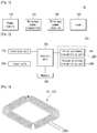
- FIG. 7 is a perspective view showing a wireless power transmitter according to an embodiment.
- FIG. 8 is a sectional view taken along line B-B' of FIG. 7 .
- FIG. 9 illustrates perspective views showing modified examples of a wireless power transmitter according to an embodiment.
- the wireless power transmitter 120 further includes a housing 270. Since the housing 270 according to the embodiment is similar to the above-described housing 270, the details will be omitted.
- the wireless transmitting unit 220 is disposed on at least one side surface as well as the rear surface of the wireless power receiver 130.
- the wireless transmitting unit may be disposed on the rear surface of the wireless power receiver 130 and in addition, at least one of the side surfaces of the wireless power receiver 130.
- the wireless transmitting unit 220 may be disposed on least one of the inner side surfaces 273, 274, 275 and 276 at an inside of the bottom surface 272 of the housing 270.
- the first wireless transmitting unit 231 may be disposed on the rear surface of the wireless power receiver 130. That is, the first wireless transmitting unit 231 may be disposed on the inner side surface at the inside of the housing 270.
- the second wireless transmitter 233 is disposed two of the side surfaces of the wireless power receiver 130. That is, the second wireless transmitting unit 233 may be disposed on two of the inner side surfaces 273, 274, 275 and 276 of the housing 270.
- the second wireless transmitting unit 233 may be disposed on two of the inner side surfaces 273, 274, 275 and 276, which face each other.
- the second wireless transmitting unit 233 may be disposed on an upper portion based on the first wireless transmitting unit 231.
- the second wireless transmitting unit 233 may be inclined to the first wireless transmitting unit 231.
- a center of the second wireless transmitting unit 233 may be aligned on the same axis with a center of the wireless power receiver 130.
- the first and second wireless transmitting units 231 and 233 are spaced apart from each other. For this reason, any interference does not occur between the first and second wireless transmitters 231 and 233.
- An overlap area of the first wireless transmitting unit 231 and the wireless power receiver 130 and an overlap area of the second wireless transmitting unit 233 and the wireless power receiver 130 extend and are secured. For this reason, the charging efficiency in the wireless power transmitter 120 for the wireless power receiver 130 may be improved.
- a position and a posture of the second wireless transmitting unit 233 are variously changeable. That is, as shown in (a) of FIG. 9 , the second wireless transmitting unit 233 may be disposed on the remaining two of the inner side surfaces 273, 274, 275 and 276, which face each other. Further, as shown in (b) and (c) of FIG. 9 , the second wireless transmitting unit 233 may be disposed on one of the inner side surfaces 273, 274, 275 and 276. Although not shown, the second wireless transmitting unit 233 may be disposed on three or four of the inner side surfaces 273, 274, 275 and 276. As shown in (a) of FIG.
- the second wireless transmitting unit 233 may be disposed in perpendicular to the first wireless transmitting unit 231. As shown in (b) of FIG. 10 , the second wireless transmitting unit 233 may be disposed at a lower portion based on the first wireless transmitting unit 231. In this case, as shown in (c) of FIG. 10 , the housing 270 may be implemented without the receiving groove 271.
- FIG. 10 (b) and (c) are illustrative examples which do not belong to the embodiment.
- the wireless power transmitter 120 may include the first and second wireless transmitting units 231 and 233, such that the wireless power receiver 130 may be charged according to various charging schemes. For this reason, the wireless power transmitter 120 may more efficiently charge the wireless power receiver 130.
- the first and second wireless power transmitting units 231 and 233 of the wireless power transmitter 120 may be spaced apart from each other and the overlap areas of each of the first and second wireless power transmitting units 231 and 233 with respect to the wireless power receiver 120 may be secured.
- the charging efficiency of the wireless power transmitter 120 to the wireless power receiver may be more improved.
- the first wireless transmitting unit 231 is installed on an inner top surface of the housing, so the overlap area between the first wireless transmitting unit 231 and the wireless power receiver 130 may be enlarged.
- the first wireless transmitting unit 231 may include an induction coil.
- the second wireless transmitting unit 233 is inclined with respect to the inner side surfaces of the housing, 5 the wireless power transmitter 120 may transmit wireless power to the wireless power receiver 130 at the high charging efficiency even if the reception coil of the wireless power receiver is disposed perpendicularly or horizontally to the top surface of the housing of the wireless power transmitter 120.
- the second wireless transmitting unit 233 may include a resonant coil.
- the first and second wireless transmitting units 231 and 233 may be disposed in a 3D space while being inclined with respect to each other such that the first and second wireless transmitting units 231 and 233 may not be perpendicular or horizontal to each other, so the degree of freedom may be maximized when charging various types of the wireless power receiver 130.
Landscapes
- Engineering & Computer Science (AREA)
- Computer Networks & Wireless Communication (AREA)
- Power Engineering (AREA)
- Signal Processing (AREA)
- Charge And Discharge Circuits For Batteries Or The Like (AREA)
- Telephone Set Structure (AREA)
Description
- The embodiment relates to a wireless power charging system, and more particularly, to a wireless power transmitter for a wireless power charging system.
- Generally, various kinds of electronic appliances employ batteries and are driven by using the power charged in the batteries. In this case, the battery of an electron appliance may be exchanged or may be recharged. The electronic appliance may include a contact terminal for making contact with an external charging apparatus in order to charge the battery. That is, the electronic appliance is electrically connected to the charging apparatus through the contact terminal. However, the contact terminal may be exposed to an outside of the electronic appliance, so that the contact terminal may be contaminated or shot-circuited due to moisture. In this case, a contact error may be generated between the contact terminal and the charging apparatus, so that the battery of the electronic appliance may not be charged.
- To solve the problems, there has been proposed a wireless power charging system for wirelessly charging an electronic appliance. The wireless power charging system includes a wireless power transmitter for wirelessly supplying power to an electronic appliance. In this case, the electronic appliance receives power according to a preset charging scheme. For this reason, in order to charge the electronic appliance, the wireless power transmitter must supply power to the electronic appliance in the same charging scheme as that of the electronic appliance. That is, when the wireless power transmitter is set in a charging scheme different from that of the electronic appliance, the wireless power transmitter does not charge the electronic appliance.
-
WO2010/093723A1 proposes to use a plurality of coils in different spatial orientation to charge a plurality of different device inside a container like a bag or a toolbox. -
US2009/106567A1 shows a charging station with several charging coils of different size all being arranged in single plane on the front side and the backside of the charging station allowing for charging of different electronic devices. -
WO2011/091528A1 describes a charger with coil structures at the back and bottom sides of a groove shaped receptacle of an electronic device. - Therefore, the embodiment provides a wireless power transmitter for effectively charging an electronic appliance.
- According to the embodiment, there is provided a wireless power transmitter for charging a wireless power receiver, which includes a first wireless transmitting unit disposed at a rear surface of the wireless power receiver and having a first charging scheme; and a second wireless transmitting unit disposed on at least one of side surfaces of the wireless power receiver and having a second charging scheme different from the first charging scheme.
- The wireless power transmitter further includes a control unit for transmitting power through the first wireless transmitting unit or the second wireless transmitting unit according to a charging scheme of the wireless power receiver.
- The second wireless transmitting unit is inclined from the first wireless power transmitter.
- The second wireless transmitting unit is perpendicular to the first wireless transmitting unit.
- A center of the second wireless transmitting unit is aligned on a same axis with a center of the wireless power receiver.
- According to the embodiment, the wireless power transmitter includes the first and second wireless power transmitting units and may charge the wireless power receiver in various charging schemes. Thus, the wireless power transmitter may more efficiently charge the wireless power receiver. In this case, the first and second wireless power transmitting units of the wireless power transmitter can be spaced apart from each other and overlap areas of the first and second wireless power transmitting units with respect to the wireless power receiver may be secured. Thus, the charging efficiency of the wireless power transmitter to the wireless power receiver may be more improved.
-
-
FIG. 1 is a block diagram showing a wireless power charging system according to an embodiment. -
FIG. 2 is a block diagram showing a wireless power transmitter according to an embodiment. -
FIG. 3 is a view showing examples of configurations of the wireless transmitting units inFIG. 2 . -
FIG. 4 is a circuit view showing equivalent circuit diagrams of the wireless transmitting units inFIG. 2 . -
FIG. 5 is a perspective view showing a wireless power transmitter according to an example. -
FIG. 6 shows sectional views taken along line A-A' ofFIG. 5 . -
FIG. 7 is a perspective view showing a wireless power transmitter according to an embodiment. -
FIG. 8 is a sectional view taken along line B-B' ofFIG. 7 . -
FIG. 9 illustrates perspective views showing modified examples of a wireless power transmitter according to an embodiment. -
FIG. 10 illustrates sectional views showing modified examples of a wireless power transmitter partially according to an embodiment. - Hereinafter, embodiments will be described with reference to accompanying drawings. In the following description, for the illustrative purpose, the same components will be assigned with the same reference numerals. If it is determined that description about well known functions or configurations may make the subject matter of the embodiments unclear, the details thereof will be omitted.
-
FIG. 1 is a block diagram showing a wireless power charging system according to an embodiment. - Referring to
FIG. 1 , a wirelesspower charging system 10 according to the embodiment includes apower supply 110, awireless power transmitter 120, awireless power receiver 130 and aload 140. In this case, thepower supply 110 and thewireless power transmitter 120 may be implemented in a single configuration. In addition, thewireless power receiver 130 and theload 140 may be implemented in a single configuration such as an electronic appliance. - The
power supply 110 supplies power to thewireless power transmitter 120. Thepower supply 110 may supply AC power to thewireless power transmitter 120. Thepower supply 110 may generate a DC voltage. Thepower supply 110 may convert the DC voltage into a preset reference value. Meanwhile, thepower supply 110 may generate an AC signal having a predetermined frequency. Thepower supply 110 may generate AC power by using the DC voltage and the AC signal. - The
wireless power transmitter 120 receives power from thepower supply 110 and wirelessly transmits power. Thewireless power transmitter 120 transmits power in various charging schemes. In this case, the charging schemes include an electromagnetic induction scheme, a resonance scheme and an RF/micro wave radiation scheme. That is, a plurality of charging schemes may be set to thewireless power transmitter 120. Thewireless power transmitter 120 may transmit power by using one of the charging schemes. Thewireless power transmitter 120 may select one from the charging schemes corresponding to thewireless power receiver 130. - The
wireless power receiver 130 receives power from thewireless power transmitter 120 and transfers the power to theload 140. In this case, thewireless power receiver 130 receives power in a preset charging scheme. The charging scheme of thewireless power receiver 130 may be one of the electromagnetic induction scheme, the resonance scheme and the RF/micro wave radiation scheme. - The
load 140 receives power from thewireless power receiver 130 and is substantially charged. Theload 140 is driven by using the power. That is, theload 140 may store the power and if necessary, theload 140 may use the power. For example, theload 140 may include a storage unit such as a battery. -
FIG. 2 is a block diagram showing a wireless power transmitter according to an embodiment.FIG. 3 is a view showing examples of configurations of the wireless transmitting units inFIG. 2 .FIG. 4 is a circuit view showing equivalent circuit diagrams of the wireless transmitting units inFIG. 2 , where (a) is an equivalent circuit diagram of a first wireless transmitting unit and (b) is an equivalent circuit diagram of a second wireless transmitting unit. - Referring to
FIG. 2 , thewireless power transmitter 120 includes aninterface unit 210, awireless transmitting unit 220, amemory 240, acontrol unit 250 and aninput unit 260. - The
interface unit 210 provides an interface between thewireless power transmitter 120 and thepower supply 110. That is, theinterface unit 210 is electrically connected to thepower supply 110. Theinterface unit 210 receives power from thepower supply 110. - The
wireless transmitting unit 220 wirelessly transmits power to thewireless power transmitter 120. Thewireless transmitting unit 220 transmits power in various charging schemes. The charging schemes include the electromagnetic induction scheme, the resonance scheme and the RF/micro wave radiation scheme. Thewireless transmitting unit 220 includes first and secondwireless transmitting units units units units FIG. 3 . That is, the coil is a plane type and can be formed by winding wires clockwise or counterclockwise. In addition, one end and the opposite end of the wire may protrude from an inside of the coil to an outside of the coil in parallel with each other. To this end, one end of the wire may cross an upper or low portion of the coil. - That is, the first
wireless transmitting unit 231 has a first charging scheme. The first charging scheme may be the electromagnetic induction scheme. The firstwireless transmitting unit 231 may be configured as shown in (a) ofFIG. 4 . That is, the firstwireless transmitting unit 231 includes a first inductor L1 and a first capacitor C1 which may be connected in parallel with each other. Thus, the firstwireless transmitting unit 231 may transmit power to thewireless power receiver 130 in the first charging scheme, that is, the electromagnetic induction scheme. - In addition, the second
wireless transmitting unit 233 has a second charging scheme. The second charging scheme may be the resonance scheme. The secondwireless transmitting unit 233 may be configured as shown in (b) ofFIG. 4 . That is, the secondwireless transmitting unit 233 includes atransmission induction coil 235 and a transmissionresonant coil 237. Thetransmission induction coil 235 includes a second inductor L2 and a second capacitor C2 which may be connected in parallel with each other. The transmissionresonant coil 237 includes a third inductor L3 and a third capacitor C3 which may be connected in parallel with each other. Thus, the secondwireless transmitting unit 233 may transmit power to thewireless power receiver 130 in the second charging scheme, that is, the resonance scheme. In detail, thetransmission induction coil 235 may transmit power to the transmissionresonant coil 237 in the electromagnetic induction scheme and the transmissionresonant coil 237 may transmit power to thewireless power receiver 130 in the resonance scheme. - The
memory 240 includes a program memory and a data memory. The program memory stores programs for controlling an operation of thewireless power transmitter 120. The program memory may stores for transmitting power in various charging schemes. The data memory stores data generated while the programs are executed. The data memory may store mapping information of the firstwireless transmitting unit 231 with the first charging scheme and mapping information of the secondwireless transmitting unit 231 with the second charging scheme. - The
control unit 250 controls an entire operation of thewireless power transmitter 120. Thecontrol unit 250 controls thewireless transmitting unit 220 to transmit power in various charging schemes. That is, thecontrol unit 250 may transmit power by using one of the charging schemes. In this case, thecontrol unit 250 may select one from the charging schemes corresponding to thewireless power receiver 130 to drive thewireless transmitting unit 220. For example, when thewireless power receiver 130 is set into the first charging scheme, thecontrol unit 250 may drive the firstwireless transmitting unit 231 to transmit power in the first charging scheme. When thewireless power receiver 130 is set into the second charging scheme, thecontrol unit 250 may drive the secondwireless transmitting unit 233 to transmit power in the second charging scheme. - The
input unit 260 generates an event for setting or executing a function of thewireless power transmitter 120. In this case, the input unit 160 may an event showing a charging scheme of thewireless power receiver 130. -
FIG. 5 is a perspective view showing a wireless power transmitter according to a first example.FIG. 6 shows sectional views taken along line A-A' ofFIG. 5 , where (a) shows one example of a wireless power transmitter and (b) shows another example of a wireless power transmitter. - Referring to
FIGS. 5 and 6 , thewireless power transmitter 120 of the example further includes ahousing 270. - At least a part of the
wireless power transmitter 120 is accommodated in thehousing 270. Thewireless transmitting unit 220 is accommodated in thehousing 270. Thehousing 270 allows a position and a posture of thewireless transmitting unit 220 to be fixed in thewireless power transmitter 120. In addition, thewireless power receiver 130 is supported in thehousing 270. That is, thehousing 270 fixes a position and a posture of thewireless power receiver 130 in thewireless power transmitter 120. Thewireless transmitting unit 220 is disposed on a rear surface of thewireless power receiver 130. - In this case, the receiving
groove 271 may be formed in thehousing 270. Thehousing 270 may receive thewireless power receiver 130 through the receivinggroove 271. An upper portion of thehousing 271 may be recessed to form the receivinggroove 271. A size of the receivinggroove 271 may excess a size of thewireless power receiver 130. Thehousing 270 may include abottom surface 272 and inner side surfaces 273, 274, 275 and 276 in the receivinggroove 271. Thebottom surface 272 may be disposed on the rear surface of thewireless power receiver 130, and the inner side surfaces 273, 274, 275 and 276 may be disposed on side surfaces of thewireless power receiver 130. That is, thewireless transmitting unit 220 may be disposed on thebottom surface 272 at an inside of thehousing 270. - The first and second
wireless transmitting units FIG. 6 . The firstwireless transmitting unit 231 may be stacked on the secondwireless transmitting unit 233. In other words, the firstwireless transmitting unit 231 may be closer to thewireless power receiver 130 as compared with the secondwireless transmitting unit 233. However, as the first and secondwireless transmitting units wireless transmitting units wireless power receiver 130 may be deteriorated due to thewireless power transmitter 120. - Meanwhile, the first and second
wireless transmitting units FIG. 6 . The first and secondwireless transmitting units wireless power receiver 130 separately from each other. In other words, the firstwireless transmitting unit 231 may be disposed in an area of the rear surface of thewireless power receiver 130 and the secondwireless transmitting unit 233 may be disposed in the remaining area of the rear surface of thewireless power receiver 130. However, as the first and secondwireless transmitting units wireless power receiver 130 separately from each other, an overlap area of the firstwireless transmitting unit 231 and thewireless power receiver 130 and an overlap area of the secondwireless transmitting unit 233 and thewireless power receiver 130 are reduced. For this reason, the charging efficiency in thewireless power transmitter 120 for thewireless power receiver 130 may be deteriorated. -
FIG. 7 is a perspective view showing a wireless power transmitter according to an embodiment.FIG. 8 is a sectional view taken along line B-B' ofFIG. 7 .FIG. 9 illustrates perspective views showing modified examples of a wireless power transmitter according to an embodiment. - Referring to
FIGS. 7 and 8 , thewireless power transmitter 120 further includes ahousing 270. Since thehousing 270 according to the embodiment is similar to the above-describedhousing 270, the details will be omitted. - However, in the
housing 270 of the embodiment, thewireless transmitting unit 220 is disposed on at least one side surface as well as the rear surface of thewireless power receiver 130. In this case, the wireless transmitting unit may be disposed on the rear surface of thewireless power receiver 130 and in addition, at least one of the side surfaces of thewireless power receiver 130. Thewireless transmitting unit 220 may be disposed on least one of the inner side surfaces 273, 274, 275 and 276 at an inside of thebottom surface 272 of thehousing 270. - In this case, the first
wireless transmitting unit 231 may be disposed on the rear surface of thewireless power receiver 130. That is, the firstwireless transmitting unit 231 may be disposed on the inner side surface at the inside of thehousing 270. Thesecond wireless transmitter 233 is disposed two of the side surfaces of thewireless power receiver 130. That is, the secondwireless transmitting unit 233 may be disposed on two of the inner side surfaces 273, 274, 275 and 276 of thehousing 270. The secondwireless transmitting unit 233 may be disposed on two of the inner side surfaces 273, 274, 275 and 276, which face each other. Thus, the secondwireless transmitting unit 233 may be disposed on an upper portion based on the firstwireless transmitting unit 231. The secondwireless transmitting unit 233 may be inclined to the firstwireless transmitting unit 231. A center of the secondwireless transmitting unit 233 may be aligned on the same axis with a center of thewireless power receiver 130. - Thus, in the
housing 270 of the embodiment, the first and secondwireless transmitting units second wireless transmitters wireless transmitting unit 231 and thewireless power receiver 130 and an overlap area of the secondwireless transmitting unit 233 and thewireless power receiver 130 extend and are secured. For this reason, the charging efficiency in thewireless power transmitter 120 for thewireless power receiver 130 may be improved. - Meanwhile, in the
wireless power transmitter 120 of the embodiment, a position and a posture of the secondwireless transmitting unit 233 are variously changeable. That is, as shown in (a) ofFIG. 9 , the secondwireless transmitting unit 233 may be disposed on the remaining two of the inner side surfaces 273, 274, 275 and 276, which face each other. Further, as shown in (b) and (c) ofFIG. 9 , the secondwireless transmitting unit 233 may be disposed on one of the inner side surfaces 273, 274, 275 and 276. Although not shown, the secondwireless transmitting unit 233 may be disposed on three or four of the inner side surfaces 273, 274, 275 and 276. As shown in (a) ofFIG. 10 , the secondwireless transmitting unit 233 may be disposed in perpendicular to the firstwireless transmitting unit 231. As shown in (b) ofFIG. 10 , the secondwireless transmitting unit 233 may be disposed at a lower portion based on the firstwireless transmitting unit 231. In this case, as shown in (c) ofFIG. 10 , thehousing 270 may be implemented without the receivinggroove 271.FIG. 10 (b) and (c) are illustrative examples which do not belong to the embodiment. - According to the embodiment, the
wireless power transmitter 120 may include the first and secondwireless transmitting units wireless power receiver 130 may be charged according to various charging schemes. For this reason, thewireless power transmitter 120 may more efficiently charge thewireless power receiver 130. In this case, the first and second wirelesspower transmitting units wireless power transmitter 120 may be spaced apart from each other and the overlap areas of each of the first and second wirelesspower transmitting units wireless power receiver 120 may be secured. Thus, the charging efficiency of thewireless power transmitter 120 to the wireless power receiver may be more improved. - According to the embodiment, the first
wireless transmitting unit 231 is installed on an inner top surface of the housing, so the overlap area between the firstwireless transmitting unit 231 and thewireless power receiver 130 may be enlarged. In this case, the firstwireless transmitting unit 231 may include an induction coil. In addition, since the secondwireless transmitting unit 233 is inclined with respect to the inner side surfaces of the housing, 5 thewireless power transmitter 120 may transmit wireless power to thewireless power receiver 130 at the high charging efficiency even if the reception coil of the wireless power receiver is disposed perpendicularly or horizontally to the top surface of the housing of thewireless power transmitter 120. In this case, the secondwireless transmitting unit 233 may include a resonant coil. - 0 [0051] In other words, the first and second
wireless transmitting units wireless transmitting units wireless power receiver 130.
Claims (10)
- A wireless power transmitter (120) for charging a wireless power receiver (130), the wireless power transmitter (120) comprising:a housing (270) having a receiving groove (271) for receiving the wireless power receiver (130),a first wireless transmitting unit (231) disposed at a rear surface of the wireless power receiver (130) and having a first charging scheme;a second wireless transmitting unit (233) disposed on at least one of side surfaces of the wireless power receiver (130) and having a second charging scheme different from the first charging scheme,a control unit (250) configured to select a charging scheme corresponding to the wireless power receiver (130), and selecting one from the first wireless transmitting unit (231) or the second wireless transmitting unit (233) according to the selected charging scheme of the wireless power receiver (130), and to transmit power through the selected wireless transmitting unit,wherein the first wireless transmitting unit (231) and the second wireless transmitting unit (233) are accommodated in the housing (270),wherein the receiving groove (271) has a bottom surface and an inner side surface that is inclined from the bottom surface,wherein the first wireless transmitting unit (231) is disposed at the bottom surface (272) of the receiving groove (271), and the second wireless transmitting unit (233) is disposed at the inclined inner side surface from the bottom surface.
- The wireless power transmitter (120) of claim 1, wherein the second wireless transmitting unit (233) is inclined from the first wireless power transmitting unit (231.
- The wireless power transmitter (120) of claim 1, wherein the second wireless transmitting unit (233) is perpendicular to the first wireless transmitting unit (231).
- The wireless power transmitter (120) of claim 1, wherein a center of the second wireless transmitting unit (233) is aligned on a same axis with a center of the wireless power receiver (130).
- The wireless power transmitter (120) of claim 1, wherein the first charging scheme is an electromagnetic induction scheme.
- The wireless power transmitter (120) of claim 1, wherein the second charging scheme is a resonance scheme.
- The wireless power transmitter (120) of claim 1, wherein the wireless power receiver (130) is received in the housing (270).
- The wireless power transmitter (120) of claim 1, wherein the housing (270) comprising a bottom surface (272) and inner side surfaces (273, 274, 275, 276);
the first wireless transmitting unit (231) disposed on the inner side at the bottom surface (272) of the housing (270), and
the second wireless transmitting unit (233) disposed on the inner side at the inner side surfaces (273, 274, 275, 276). - The wireless power transmitter (120) of claim 8, wherein the second wireless transmitter (232) is disposed two of the side surfaces of the wireless power receiver (130).
- The wireless power transmitter (120) of claim 1, wherein the first wireless transmitting unit (231) and second wireless transmitting units (233) are spaced apart from each other.
Applications Claiming Priority (2)
| Application Number | Priority Date | Filing Date | Title |
|---|---|---|---|
| KR1020130120504A KR20150052367A (en) | 2013-10-10 | 2013-10-10 | Wireless apparatus for transmitting power |
| PCT/KR2014/009495 WO2015053567A1 (en) | 2013-10-10 | 2014-10-09 | Wireless power transmitter |
Publications (3)
| Publication Number | Publication Date |
|---|---|
| EP3061175A1 EP3061175A1 (en) | 2016-08-31 |
| EP3061175A4 EP3061175A4 (en) | 2017-06-28 |
| EP3061175B1 true EP3061175B1 (en) | 2019-05-01 |
Family
ID=52809139
Family Applications (1)
| Application Number | Title | Priority Date | Filing Date |
|---|---|---|---|
| EP14852170.1A Active EP3061175B1 (en) | 2013-10-10 | 2014-10-09 | Wireless power transmitter |
Country Status (6)
| Country | Link |
|---|---|
| US (2) | US9553478B2 (en) |
| EP (1) | EP3061175B1 (en) |
| JP (1) | JP6450377B2 (en) |
| KR (1) | KR20150052367A (en) |
| CN (1) | CN105594090B (en) |
| WO (1) | WO2015053567A1 (en) |
Families Citing this family (8)
| Publication number | Priority date | Publication date | Assignee | Title |
|---|---|---|---|---|
| KR20150052367A (en) * | 2013-10-10 | 2015-05-14 | 엘지이노텍 주식회사 | Wireless apparatus for transmitting power |
| KR102428009B1 (en) * | 2015-06-08 | 2022-08-02 | 주식회사 위츠 | Wireless power transmitter |
| CN107925250B (en) * | 2015-08-28 | 2021-03-19 | Tdk株式会社 | Contactless power supply device and contactless power transmission device |
| KR102584842B1 (en) * | 2015-09-03 | 2023-10-05 | 엘지이노텍 주식회사 | Chair for sensing pressure |
| KR20170076170A (en) * | 2015-12-24 | 2017-07-04 | 엘지이노텍 주식회사 | Wireless Power Transmitter Providing Multi-Mode |
| EP3565087B1 (en) * | 2017-02-22 | 2021-03-31 | Samsung Electronics Co., Ltd. | Wireless power transmitter |
| CN112152334B (en) * | 2020-09-09 | 2022-06-03 | 湖北工业大学 | Anti-deviation coupling mechanism for wireless power transmission |
| US20240159427A1 (en) * | 2022-11-11 | 2024-05-16 | Rheem Manufacturing Company | Systems and methods for powering water heating devices using wireless power transmissions |
Family Cites Families (26)
| Publication number | Priority date | Publication date | Assignee | Title |
|---|---|---|---|---|
| JP3719510B2 (en) | 2002-04-08 | 2005-11-24 | アルプス電気株式会社 | Storage room with contactless charger |
| JP4036813B2 (en) * | 2003-09-30 | 2008-01-23 | シャープ株式会社 | Non-contact power supply system |
| JP5363494B2 (en) * | 2007-10-17 | 2013-12-11 | アクセス ビジネス グループ インターナショナル リミテッド ライアビリティ カンパニー | Wireless power supply system for laptops and portable electronic devices |
| JP2010193701A (en) | 2009-01-22 | 2010-09-02 | Sanyo Electric Co Ltd | Noncontact charger |
| TW201042880A (en) * | 2009-02-10 | 2010-12-01 | Qualcomm Inc | Wireless power transfer for furnishings and building elements |
| US9312924B2 (en) * | 2009-02-10 | 2016-04-12 | Qualcomm Incorporated | Systems and methods relating to multi-dimensional wireless charging |
| US9407327B2 (en) * | 2009-02-13 | 2016-08-02 | Qualcomm Incorporated | Wireless power for chargeable and charging devices |
| JP5347708B2 (en) * | 2009-05-18 | 2013-11-20 | トヨタ自動車株式会社 | Coil unit, non-contact power transmission device, non-contact power feeding system, and vehicle |
| RU2540896C2 (en) * | 2009-07-24 | 2015-02-10 | Эксесс Бизнесс Груп Интернешнл Ллс | Power supply |
| US8373388B2 (en) | 2009-12-11 | 2013-02-12 | Electronics And Telecommunications Research Institute | Portable device and battery charging method thereof |
| KR20110066827A (en) * | 2009-12-11 | 2011-06-17 | 한국전자통신연구원 | Mobile device and its battery charging method |
| CA2788091C (en) * | 2010-01-27 | 2017-01-03 | Cynetic Designs Ltd. | Modular pocket with inductive power and data |
| KR101830734B1 (en) | 2010-11-03 | 2018-02-21 | 엘지전자 주식회사 | Wireless power transmission method and apparatus |
| US8754351B2 (en) | 2010-11-30 | 2014-06-17 | Bose Corporation | Induction cooking |
| JP5439416B2 (en) * | 2011-03-04 | 2014-03-12 | 株式会社東芝 | Wireless power transmission device |
| JPWO2013005415A1 (en) | 2011-07-04 | 2015-02-23 | 日本電気株式会社 | Wireless power transmission apparatus and method, and repeater |
| KR101811292B1 (en) | 2011-07-06 | 2017-12-26 | 엘지전자 주식회사 | Wireless power transmitter and wireless power receiver having fuction of resonance frequency control |
| KR20130024757A (en) | 2011-08-29 | 2013-03-08 | 주식회사 케이더파워 | The wireless charging system with the different charging ways |
| KR101114601B1 (en) | 2011-09-02 | 2012-02-24 | 한국과학기술원 | Power supply device for electric vehicle |
| KR101305579B1 (en) * | 2011-09-09 | 2013-09-09 | 엘지이노텍 주식회사 | Wireless power relay apparatus and wireless power transmission system |
| JP5890170B2 (en) | 2011-09-29 | 2016-03-22 | 日立マクセル株式会社 | Non-contact power transmission apparatus and non-contact power transmission method |
| JP5895449B2 (en) * | 2011-10-28 | 2016-03-30 | 日立化成株式会社 | Non-contact power transmission device and non-contact power transmission system |
| JP2013106428A (en) * | 2011-11-14 | 2013-05-30 | Panasonic Corp | Charging base for contactless charging |
| WO2014055658A2 (en) * | 2012-10-02 | 2014-04-10 | Witricity Corporation | Wireless power transfer |
| KR101787796B1 (en) * | 2013-05-03 | 2017-10-18 | 삼성전자주식회사 | Wireless power transmitter, wireless power receiver and method for controlling each thereof |
| KR20150052367A (en) * | 2013-10-10 | 2015-05-14 | 엘지이노텍 주식회사 | Wireless apparatus for transmitting power |
-
2013
- 2013-10-10 KR KR1020130120504A patent/KR20150052367A/en not_active Ceased
-
2014
- 2014-10-09 JP JP2016521987A patent/JP6450377B2/en not_active Expired - Fee Related
- 2014-10-09 WO PCT/KR2014/009495 patent/WO2015053567A1/en not_active Ceased
- 2014-10-09 US US14/510,752 patent/US9553478B2/en active Active - Reinstated
- 2014-10-09 EP EP14852170.1A patent/EP3061175B1/en active Active
- 2014-10-09 CN CN201480054828.3A patent/CN105594090B/en not_active Expired - Fee Related
-
2016
- 2016-12-12 US US15/375,280 patent/US9837851B2/en not_active Expired - Fee Related
Non-Patent Citations (1)
| Title |
|---|
| None * |
Also Published As
| Publication number | Publication date |
|---|---|
| EP3061175A4 (en) | 2017-06-28 |
| WO2015053567A1 (en) | 2015-04-16 |
| US20170104360A1 (en) | 2017-04-13 |
| EP3061175A1 (en) | 2016-08-31 |
| KR20150052367A (en) | 2015-05-14 |
| CN105594090A (en) | 2016-05-18 |
| US9553478B2 (en) | 2017-01-24 |
| CN105594090B (en) | 2019-03-22 |
| JP6450377B2 (en) | 2019-01-09 |
| US9837851B2 (en) | 2017-12-05 |
| US20150102773A1 (en) | 2015-04-16 |
| JP2016539610A (en) | 2016-12-15 |
Similar Documents
| Publication | Publication Date | Title |
|---|---|---|
| EP3061175B1 (en) | Wireless power transmitter | |
| US10784720B2 (en) | Transmission coil module for wireless power transmitter | |
| US9667085B2 (en) | Wireless charger for electronic device | |
| US9866058B2 (en) | Power feeding device, power receiving device, and wireless power transmission device | |
| KR101305579B1 (en) | Wireless power relay apparatus and wireless power transmission system | |
| US9337691B2 (en) | Wireless charging set | |
| US20140091636A1 (en) | Wireless power transfer | |
| US11133706B2 (en) | Wireless power transmitter | |
| WO2012067522A1 (en) | A wirelessly rechargeable battery and power transmitter | |
| US11742687B2 (en) | Wirelessly powered battery pack for retrofit in legacy devices | |
| US10090717B2 (en) | Power receiving device and power feeding device | |
| KR101684109B1 (en) | Wireless apparatus for transmitting power | |
| KR101522572B1 (en) | Wireless Charger System for Mobile Battery Device | |
| KR101756677B1 (en) | Wireless charger matrix core and wireless charging system using the same | |
| KR20160050445A (en) | Wireless power charging apparatus | |
| KR20170002247A (en) | Wireless charging device | |
| KR102019074B1 (en) | Wireless apparatus for transmitting power | |
| KR20130123082A (en) | Wireless power transmitter and wireless power receiver | |
| US20220352755A1 (en) | Wirelessly Powered Battery Pack For Retrofit In Battery Powered Devices | |
| EP4331079A1 (en) | Wirelessly powered battery pack for retrofit in legacy devices |
Legal Events
| Date | Code | Title | Description |
|---|---|---|---|
| PUAI | Public reference made under article 153(3) epc to a published international application that has entered the european phase |
Free format text: ORIGINAL CODE: 0009012 |
|
| 17P | Request for examination filed |
Effective date: 20160412 |
|
| AK | Designated contracting states |
Kind code of ref document: A1 Designated state(s): AL AT BE BG CH CY CZ DE DK EE ES FI FR GB GR HR HU IE IS IT LI LT LU LV MC MK MT NL NO PL PT RO RS SE SI SK SM TR |
|
| AX | Request for extension of the european patent |
Extension state: BA ME |
|
| DAX | Request for extension of the european patent (deleted) | ||
| RAP3 | Party data changed (applicant data changed or rights of an application transferred) |
Owner name: LG INNOTEK CO., LTD. |
|
| RAP1 | Party data changed (applicant data changed or rights of an application transferred) |
Owner name: LG INNOTEK CO., LTD. |
|
| A4 | Supplementary search report drawn up and despatched |
Effective date: 20170531 |
|
| RIC1 | Information provided on ipc code assigned before grant |
Ipc: H02J 50/40 20160101ALI20170524BHEP Ipc: H02J 50/12 20160101AFI20170524BHEP Ipc: H02J 7/02 20160101ALI20170524BHEP Ipc: H02J 7/00 20060101ALI20170524BHEP |
|
| REG | Reference to a national code |
Ref country code: DE Ref legal event code: R079 Ref document number: 602014045988 Country of ref document: DE Free format text: PREVIOUS MAIN CLASS: H02J0050000000 Ipc: H02J0050120000 |
|
| GRAP | Despatch of communication of intention to grant a patent |
Free format text: ORIGINAL CODE: EPIDOSNIGR1 |
|
| STAA | Information on the status of an ep patent application or granted ep patent |
Free format text: STATUS: GRANT OF PATENT IS INTENDED |
|
| RIC1 | Information provided on ipc code assigned before grant |
Ipc: H02J 7/02 20160101ALI20181031BHEP Ipc: H02J 50/40 20160101ALI20181031BHEP Ipc: H02J 50/12 20160101AFI20181031BHEP Ipc: H02J 7/00 20060101ALI20181031BHEP |
|
| INTG | Intention to grant announced |
Effective date: 20181121 |
|
| GRAS | Grant fee paid |
Free format text: ORIGINAL CODE: EPIDOSNIGR3 |
|
| GRAA | (expected) grant |
Free format text: ORIGINAL CODE: 0009210 |
|
| STAA | Information on the status of an ep patent application or granted ep patent |
Free format text: STATUS: THE PATENT HAS BEEN GRANTED |
|
| AK | Designated contracting states |
Kind code of ref document: B1 Designated state(s): AL AT BE BG CH CY CZ DE DK EE ES FI FR GB GR HR HU IE IS IT LI LT LU LV MC MK MT NL NO PL PT RO RS SE SI SK SM TR |
|
| REG | Reference to a national code |
Ref country code: GB Ref legal event code: FG4D |
|
| REG | Reference to a national code |
Ref country code: CH Ref legal event code: EP Ref country code: AT Ref legal event code: REF Ref document number: 1128222 Country of ref document: AT Kind code of ref document: T Effective date: 20190515 |
|
| REG | Reference to a national code |
Ref country code: DE Ref legal event code: R096 Ref document number: 602014045988 Country of ref document: DE |
|
| REG | Reference to a national code |
Ref country code: IE Ref legal event code: FG4D |
|
| REG | Reference to a national code |
Ref country code: NL Ref legal event code: MP Effective date: 20190501 |
|
| REG | Reference to a national code |
Ref country code: LT Ref legal event code: MG4D |
|
| PG25 | Lapsed in a contracting state [announced via postgrant information from national office to epo] |
Ref country code: ES Free format text: LAPSE BECAUSE OF FAILURE TO SUBMIT A TRANSLATION OF THE DESCRIPTION OR TO PAY THE FEE WITHIN THE PRESCRIBED TIME-LIMIT Effective date: 20190501 Ref country code: HR Free format text: LAPSE BECAUSE OF FAILURE TO SUBMIT A TRANSLATION OF THE DESCRIPTION OR TO PAY THE FEE WITHIN THE PRESCRIBED TIME-LIMIT Effective date: 20190501 Ref country code: NL Free format text: LAPSE BECAUSE OF FAILURE TO SUBMIT A TRANSLATION OF THE DESCRIPTION OR TO PAY THE FEE WITHIN THE PRESCRIBED TIME-LIMIT Effective date: 20190501 Ref country code: LT Free format text: LAPSE BECAUSE OF FAILURE TO SUBMIT A TRANSLATION OF THE DESCRIPTION OR TO PAY THE FEE WITHIN THE PRESCRIBED TIME-LIMIT Effective date: 20190501 Ref country code: NO Free format text: LAPSE BECAUSE OF FAILURE TO SUBMIT A TRANSLATION OF THE DESCRIPTION OR TO PAY THE FEE WITHIN THE PRESCRIBED TIME-LIMIT Effective date: 20190801 Ref country code: PT Free format text: LAPSE BECAUSE OF FAILURE TO SUBMIT A TRANSLATION OF THE DESCRIPTION OR TO PAY THE FEE WITHIN THE PRESCRIBED TIME-LIMIT Effective date: 20190901 Ref country code: FI Free format text: LAPSE BECAUSE OF FAILURE TO SUBMIT A TRANSLATION OF THE DESCRIPTION OR TO PAY THE FEE WITHIN THE PRESCRIBED TIME-LIMIT Effective date: 20190501 Ref country code: AL Free format text: LAPSE BECAUSE OF FAILURE TO SUBMIT A TRANSLATION OF THE DESCRIPTION OR TO PAY THE FEE WITHIN THE PRESCRIBED TIME-LIMIT Effective date: 20190501 Ref country code: SE Free format text: LAPSE BECAUSE OF FAILURE TO SUBMIT A TRANSLATION OF THE DESCRIPTION OR TO PAY THE FEE WITHIN THE PRESCRIBED TIME-LIMIT Effective date: 20190501 |
|
| PG25 | Lapsed in a contracting state [announced via postgrant information from national office to epo] |
Ref country code: LV Free format text: LAPSE BECAUSE OF FAILURE TO SUBMIT A TRANSLATION OF THE DESCRIPTION OR TO PAY THE FEE WITHIN THE PRESCRIBED TIME-LIMIT Effective date: 20190501 Ref country code: GR Free format text: LAPSE BECAUSE OF FAILURE TO SUBMIT A TRANSLATION OF THE DESCRIPTION OR TO PAY THE FEE WITHIN THE PRESCRIBED TIME-LIMIT Effective date: 20190802 Ref country code: RS Free format text: LAPSE BECAUSE OF FAILURE TO SUBMIT A TRANSLATION OF THE DESCRIPTION OR TO PAY THE FEE WITHIN THE PRESCRIBED TIME-LIMIT Effective date: 20190501 Ref country code: BG Free format text: LAPSE BECAUSE OF FAILURE TO SUBMIT A TRANSLATION OF THE DESCRIPTION OR TO PAY THE FEE WITHIN THE PRESCRIBED TIME-LIMIT Effective date: 20190801 |
|
| REG | Reference to a national code |
Ref country code: AT Ref legal event code: MK05 Ref document number: 1128222 Country of ref document: AT Kind code of ref document: T Effective date: 20190501 |
|
| PG25 | Lapsed in a contracting state [announced via postgrant information from national office to epo] |
Ref country code: IS Free format text: LAPSE BECAUSE OF FAILURE TO SUBMIT A TRANSLATION OF THE DESCRIPTION OR TO PAY THE FEE WITHIN THE PRESCRIBED TIME-LIMIT Effective date: 20190901 |
|
| PG25 | Lapsed in a contracting state [announced via postgrant information from national office to epo] |
Ref country code: RO Free format text: LAPSE BECAUSE OF FAILURE TO SUBMIT A TRANSLATION OF THE DESCRIPTION OR TO PAY THE FEE WITHIN THE PRESCRIBED TIME-LIMIT Effective date: 20190501 Ref country code: CZ Free format text: LAPSE BECAUSE OF FAILURE TO SUBMIT A TRANSLATION OF THE DESCRIPTION OR TO PAY THE FEE WITHIN THE PRESCRIBED TIME-LIMIT Effective date: 20190501 Ref country code: EE Free format text: LAPSE BECAUSE OF FAILURE TO SUBMIT A TRANSLATION OF THE DESCRIPTION OR TO PAY THE FEE WITHIN THE PRESCRIBED TIME-LIMIT Effective date: 20190501 Ref country code: AT Free format text: LAPSE BECAUSE OF FAILURE TO SUBMIT A TRANSLATION OF THE DESCRIPTION OR TO PAY THE FEE WITHIN THE PRESCRIBED TIME-LIMIT Effective date: 20190501 Ref country code: SK Free format text: LAPSE BECAUSE OF FAILURE TO SUBMIT A TRANSLATION OF THE DESCRIPTION OR TO PAY THE FEE WITHIN THE PRESCRIBED TIME-LIMIT Effective date: 20190501 Ref country code: DK Free format text: LAPSE BECAUSE OF FAILURE TO SUBMIT A TRANSLATION OF THE DESCRIPTION OR TO PAY THE FEE WITHIN THE PRESCRIBED TIME-LIMIT Effective date: 20190501 |
|
| REG | Reference to a national code |
Ref country code: DE Ref legal event code: R097 Ref document number: 602014045988 Country of ref document: DE |
|
| PG25 | Lapsed in a contracting state [announced via postgrant information from national office to epo] |
Ref country code: IT Free format text: LAPSE BECAUSE OF FAILURE TO SUBMIT A TRANSLATION OF THE DESCRIPTION OR TO PAY THE FEE WITHIN THE PRESCRIBED TIME-LIMIT Effective date: 20190501 Ref country code: SM Free format text: LAPSE BECAUSE OF FAILURE TO SUBMIT A TRANSLATION OF THE DESCRIPTION OR TO PAY THE FEE WITHIN THE PRESCRIBED TIME-LIMIT Effective date: 20190501 |
|
| PLBE | No opposition filed within time limit |
Free format text: ORIGINAL CODE: 0009261 |
|
| STAA | Information on the status of an ep patent application or granted ep patent |
Free format text: STATUS: NO OPPOSITION FILED WITHIN TIME LIMIT |
|
| PG25 | Lapsed in a contracting state [announced via postgrant information from national office to epo] |
Ref country code: TR Free format text: LAPSE BECAUSE OF FAILURE TO SUBMIT A TRANSLATION OF THE DESCRIPTION OR TO PAY THE FEE WITHIN THE PRESCRIBED TIME-LIMIT Effective date: 20190501 |
|
| 26N | No opposition filed |
Effective date: 20200204 |
|
| PG25 | Lapsed in a contracting state [announced via postgrant information from national office to epo] |
Ref country code: PL Free format text: LAPSE BECAUSE OF FAILURE TO SUBMIT A TRANSLATION OF THE DESCRIPTION OR TO PAY THE FEE WITHIN THE PRESCRIBED TIME-LIMIT Effective date: 20190501 |
|
| PG25 | Lapsed in a contracting state [announced via postgrant information from national office to epo] |
Ref country code: SI Free format text: LAPSE BECAUSE OF FAILURE TO SUBMIT A TRANSLATION OF THE DESCRIPTION OR TO PAY THE FEE WITHIN THE PRESCRIBED TIME-LIMIT Effective date: 20190501 Ref country code: MC Free format text: LAPSE BECAUSE OF FAILURE TO SUBMIT A TRANSLATION OF THE DESCRIPTION OR TO PAY THE FEE WITHIN THE PRESCRIBED TIME-LIMIT Effective date: 20190501 |
|
| REG | Reference to a national code |
Ref country code: CH Ref legal event code: PL |
|
| PG25 | Lapsed in a contracting state [announced via postgrant information from national office to epo] |
Ref country code: LU Free format text: LAPSE BECAUSE OF NON-PAYMENT OF DUE FEES Effective date: 20191009 Ref country code: CH Free format text: LAPSE BECAUSE OF NON-PAYMENT OF DUE FEES Effective date: 20191031 Ref country code: LI Free format text: LAPSE BECAUSE OF NON-PAYMENT OF DUE FEES Effective date: 20191031 |
|
| REG | Reference to a national code |
Ref country code: BE Ref legal event code: MM Effective date: 20191031 |
|
| PG25 | Lapsed in a contracting state [announced via postgrant information from national office to epo] |
Ref country code: BE Free format text: LAPSE BECAUSE OF NON-PAYMENT OF DUE FEES Effective date: 20191031 |
|
| GBPC | Gb: european patent ceased through non-payment of renewal fee |
Effective date: 20191009 |
|
| PG25 | Lapsed in a contracting state [announced via postgrant information from national office to epo] |
Ref country code: IE Free format text: LAPSE BECAUSE OF NON-PAYMENT OF DUE FEES Effective date: 20191009 Ref country code: FR Free format text: LAPSE BECAUSE OF NON-PAYMENT OF DUE FEES Effective date: 20191031 Ref country code: GB Free format text: LAPSE BECAUSE OF NON-PAYMENT OF DUE FEES Effective date: 20191009 |
|
| REG | Reference to a national code |
Ref country code: DE Ref legal event code: R082 Ref document number: 602014045988 Country of ref document: DE Representative=s name: PETERREINS SCHLEY PATENT- UND RECHTSANWAELTE P, DE |
|
| REG | Reference to a national code |
Ref country code: DE Ref legal event code: R081 Ref document number: 602014045988 Country of ref document: DE Owner name: NERA INNOVATIONS LTD., IE Free format text: FORMER OWNER: LG INNOTEK CO., LTD, SEOUL, KR Ref country code: DE Ref legal event code: R082 Ref document number: 602014045988 Country of ref document: DE Representative=s name: PETERREINS SCHLEY PATENT- UND RECHTSANWAELTE P, DE Ref country code: DE Ref legal event code: R081 Ref document number: 602014045988 Country of ref document: DE Owner name: SCRAMOGE TECHNOLOGY LIMITED, IE Free format text: FORMER OWNER: LG INNOTEK CO., LTD, SEOUL, KR |
|
| PG25 | Lapsed in a contracting state [announced via postgrant information from national office to epo] |
Ref country code: CY Free format text: LAPSE BECAUSE OF FAILURE TO SUBMIT A TRANSLATION OF THE DESCRIPTION OR TO PAY THE FEE WITHIN THE PRESCRIBED TIME-LIMIT Effective date: 20190501 |
|
| PG25 | Lapsed in a contracting state [announced via postgrant information from national office to epo] |
Ref country code: MT Free format text: LAPSE BECAUSE OF FAILURE TO SUBMIT A TRANSLATION OF THE DESCRIPTION OR TO PAY THE FEE WITHIN THE PRESCRIBED TIME-LIMIT Effective date: 20190501 Ref country code: HU Free format text: LAPSE BECAUSE OF FAILURE TO SUBMIT A TRANSLATION OF THE DESCRIPTION OR TO PAY THE FEE WITHIN THE PRESCRIBED TIME-LIMIT; INVALID AB INITIO Effective date: 20141009 |
|
| PG25 | Lapsed in a contracting state [announced via postgrant information from national office to epo] |
Ref country code: MK Free format text: LAPSE BECAUSE OF FAILURE TO SUBMIT A TRANSLATION OF THE DESCRIPTION OR TO PAY THE FEE WITHIN THE PRESCRIBED TIME-LIMIT Effective date: 20190501 |
|
| REG | Reference to a national code |
Ref country code: DE Ref legal event code: R081 Ref document number: 602014045988 Country of ref document: DE Owner name: NERA INNOVATIONS LTD., IE Free format text: FORMER OWNER: SCRAMOGE TECHNOLOGY LIMITED, DUBLIN, IE |
|
| PGFP | Annual fee paid to national office [announced via postgrant information from national office to epo] |
Ref country code: DE Payment date: 20250919 Year of fee payment: 12 |