EP3028821A1 - Control method for a hand-held machine tool - Google Patents
Control method for a hand-held machine tool Download PDFInfo
- Publication number
- EP3028821A1 EP3028821A1 EP14196019.5A EP14196019A EP3028821A1 EP 3028821 A1 EP3028821 A1 EP 3028821A1 EP 14196019 A EP14196019 A EP 14196019A EP 3028821 A1 EP3028821 A1 EP 3028821A1
- Authority
- EP
- European Patent Office
- Prior art keywords
- working axis
- tool
- acceleration
- setpoint
- absorber
- Prior art date
- Legal status (The legal status is an assumption and is not a legal conclusion. Google has not performed a legal analysis and makes no representation as to the accuracy of the status listed.)
- Withdrawn
Links
- 238000000034 method Methods 0.000 title claims description 4
- 239000006096 absorbing agent Substances 0.000 claims abstract description 20
- 230000007246 mechanism Effects 0.000 claims abstract description 17
- 230000001133 acceleration Effects 0.000 claims abstract description 16
- 238000009527 percussion Methods 0.000 claims abstract description 9
- 230000035559 beat frequency Effects 0.000 description 5
- 238000013016 damping Methods 0.000 description 5
- 230000000737 periodic effect Effects 0.000 description 5
- 230000009467 reduction Effects 0.000 description 5
- 230000008859 change Effects 0.000 description 2
- 230000005284 excitation Effects 0.000 description 2
- 230000009471 action Effects 0.000 description 1
- 230000006399 behavior Effects 0.000 description 1
- 230000006835 compression Effects 0.000 description 1
- 238000007906 compression Methods 0.000 description 1
- 230000008878 coupling Effects 0.000 description 1
- 238000010168 coupling process Methods 0.000 description 1
- 238000005859 coupling reaction Methods 0.000 description 1
- 230000003247 decreasing effect Effects 0.000 description 1
- 230000001419 dependent effect Effects 0.000 description 1
- 230000000694 effects Effects 0.000 description 1
- 210000003746 feather Anatomy 0.000 description 1
- 244000052769 pathogen Species 0.000 description 1
- 230000001717 pathogenic effect Effects 0.000 description 1
- 239000000758 substrate Substances 0.000 description 1
Images

Classifications
-
- B—PERFORMING OPERATIONS; TRANSPORTING
- B25—HAND TOOLS; PORTABLE POWER-DRIVEN TOOLS; MANIPULATORS
- B25D—PERCUSSIVE TOOLS
- B25D17/00—Details of, or accessories for, portable power-driven percussive tools
- B25D17/24—Damping the reaction force
-
- F—MECHANICAL ENGINEERING; LIGHTING; HEATING; WEAPONS; BLASTING
- F16—ENGINEERING ELEMENTS AND UNITS; GENERAL MEASURES FOR PRODUCING AND MAINTAINING EFFECTIVE FUNCTIONING OF MACHINES OR INSTALLATIONS; THERMAL INSULATION IN GENERAL
- F16F—SPRINGS; SHOCK-ABSORBERS; MEANS FOR DAMPING VIBRATION
- F16F7/00—Vibration-dampers; Shock-absorbers
- F16F7/10—Vibration-dampers; Shock-absorbers using inertia effect
- F16F7/104—Vibration-dampers; Shock-absorbers using inertia effect the inertia member being resiliently mounted
-
- B—PERFORMING OPERATIONS; TRANSPORTING
- B25—HAND TOOLS; PORTABLE POWER-DRIVEN TOOLS; MANIPULATORS
- B25D—PERCUSSIVE TOOLS
- B25D2211/00—Details of portable percussive tools with electromotor or other motor drive
- B25D2211/06—Means for driving the impulse member
- B25D2211/068—Crank-actuated impulse-driving mechanisms
-
- B—PERFORMING OPERATIONS; TRANSPORTING
- B25—HAND TOOLS; PORTABLE POWER-DRIVEN TOOLS; MANIPULATORS
- B25D—PERCUSSIVE TOOLS
- B25D2216/00—Details of portable percussive machines with superimposed rotation, the rotational movement of the output shaft of a motor being modified to generate axial impacts on the tool bit
- B25D2216/0007—Details of percussion or rotation modes
- B25D2216/0038—Tools having a rotation-only mode
-
- B—PERFORMING OPERATIONS; TRANSPORTING
- B25—HAND TOOLS; PORTABLE POWER-DRIVEN TOOLS; MANIPULATORS
- B25D—PERCUSSIVE TOOLS
- B25D2217/00—Details of, or accessories for, portable power-driven percussive tools
- B25D2217/0073—Arrangements for damping of the reaction force
- B25D2217/0076—Arrangements for damping of the reaction force by use of counterweights
- B25D2217/0092—Arrangements for damping of the reaction force by use of counterweights being spring-mounted
-
- B—PERFORMING OPERATIONS; TRANSPORTING
- B25—HAND TOOLS; PORTABLE POWER-DRIVEN TOOLS; MANIPULATORS
- B25D—PERCUSSIVE TOOLS
- B25D2250/00—General details of portable percussive tools; Components used in portable percussive tools
- B25D2250/005—Adjustable tool components; Adjustable parameters
-
- B—PERFORMING OPERATIONS; TRANSPORTING
- B25—HAND TOOLS; PORTABLE POWER-DRIVEN TOOLS; MANIPULATORS
- B25D—PERCUSSIVE TOOLS
- B25D2250/00—General details of portable percussive tools; Components used in portable percussive tools
- B25D2250/175—Phase shift of tool components
-
- B—PERFORMING OPERATIONS; TRANSPORTING
- B25—HAND TOOLS; PORTABLE POWER-DRIVEN TOOLS; MANIPULATORS
- B25D—PERCUSSIVE TOOLS
- B25D2250/00—General details of portable percussive tools; Components used in portable percussive tools
- B25D2250/195—Regulation means
- B25D2250/201—Regulation means for speed, e.g. drilling or percussion speed
-
- B—PERFORMING OPERATIONS; TRANSPORTING
- B25—HAND TOOLS; PORTABLE POWER-DRIVEN TOOLS; MANIPULATORS
- B25D—PERCUSSIVE TOOLS
- B25D2250/00—General details of portable percussive tools; Components used in portable percussive tools
- B25D2250/221—Sensors
Definitions
- the present invention relates to a control method for a portable power tool with a damper for damping periodic vibrations.
- US8434565 BB describes a rotary hammer whose percussion drive a chisel with a striking frequency in a subsoil.
- the vibrations occurring with the beat frequency are damped by a damper.
- the absorber has a freely suspended oscillator, which can oscillate back and forth along the direction of impact from a rest position. Feathers drive the oscillator back to the rest position after a deflection.
- the mass of the vibrator and the spring strength of the springs are tuned to the beat frequency.
- the hand tool has a tool holder for holding a tool on a working axis.
- a striking mechanism has a racket that moves periodically on the working axis.
- a drive control of the impact mechanism controls the stroke rate to a setpoint.
- An absorber has a longitudinally movable about the working axis about a rest position oscillator and one or more the oscillator to the rest position driving back springs.
- a calibration phase comprises the following steps: detecting an acceleration with the acceleration sensor, determining a minimum of the acceleration by varying the beat number in a range between 90% and 110% of the target value and setting the target value to the beat number associated with the determined minimum.
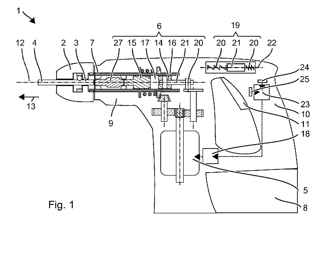
- Fig. 1 shows as an example of a hand tool machine schematically a hammer drill 1.
- the hammer drill 1 has a tool holder 2, in which a shank end 3 of a tool, for example one of the drill 4, can be used.
- a primary drive of the hammer drill 1 is a motor 5, which drives a striking mechanism 6 and an output shaft 7 .
- a battery pack 8 or a power line supplies the motor 5 with power.
- the pneumatic impact mechanism 6, and preferably the further drive components are disposed within a machine housing. 9
- a user can guide the hammer drill 1 by means of a handle 10 , which is fixed to the machine housing 9 .
- the motor 5 and thus the hammer drill 1 can be taken by means of a system switch 11 in operation. In operation, the hammer drill 1 rotates the drill 4 continuously about a working axis 12 and can beat the drill 4 in the direction of impact 13 along the working axis 12 in a substrate.
- the pneumatic percussion 6 has a pathogen 14 and a racket 15, which are guided in a guide tube 16 along the working axis 12 movable.
- the exciter 14 and the racket 15 complete a pneumatic chamber 17 between them.
- the exciter 14 is periodically moved back and forth by the motor 5 on the working axis 12 .
- the pneumatic chamber 17 forms an air spring, which binds the racket 15 to the movement of the exciter 14 .
- the period is determined by the forced movement of the exciter 14 .
- a motor controller 18 controls the speed of the motor 5 to a target value.
- the speed specifies the period duration.
- the desired value of the speed is designed with regard to an efficient pneumatic coupling of the racket 15 to the exciter 14 .
- the impact number of impact mechanism 6 is the inverse of the period and is typically in the range between 10 Hz and 100 Hz.
- the periodic movements of the exciter 14 and the racket 15 impart vibrations to the machine housing 9 which are transmitted to the handle 10 .
- the user senses in particular the acceleration of the racket 15 in the compression point.
- a damper 19 in the machine housing 9 reduces the amplitude of the vibrations.
- the absorber 19 has a vibrator 21 suspended from one or more springs 20 Inertia of the vibrator 21 causes a relative movement of the vibrator 21 relative to the vibrating machine housing 9.
- the periodic vibrations of the percussion mechanism 6 along the working axis 12 lead to a periodic deflection of the vibrator 21 relative to a rest position in the machine housing 9.
- Only the springs 20 couple the Oscillator 21 to the machine housing 9 and handle 10 and exert on the vibrator 21 at a deflection of a restoring force in the rest position.
- the oscillator 21 oscillates between a tool-near reversal point and a tool-remote reversal point.
- the periodicity is equal to the beat frequency of the periodic excitation.
- the amplitude of the deflection depends on the amplitude of the vibrations and the beat frequency.
- the exemplary absorber 19 has a guided in a linear bearing along an axis 22 oscillator 21.
- the axis 22 is parallel or inclined by less than 30 degrees relative to the working axis 12 .
- the springs 20 are, for example, helical springs with which the oscillator 21 is supported along the axis 22 on the machine housing 9 .
- An alternative absorber has a vibrator guided on a curved path.
- the oscillator is suspended by a pendulum arm on the machine housing 9 .
- the pendulum arm is a spiral spring, which is arranged perpendicular to the working axis.
- the vibrating absorber 19 causes a reduction in the vibrations transmitted to the handle 10 .
- the reduction is not effected by a dissipative effect of the absorber 19. Rather, the absorber 19 forms with the percussion mechanism 6 a continuous oscillating system with a vibration node.
- the system is tuned so that the connection point of the system to the machine housing 9 and the handle 10 coincides with the vibration node.
- the optimal reduction is achieved when the beat frequency is equal to the natural frequency of the absorber 19 .
- the natural frequency is the frequency with which the absorber 19 oscillates after a single deflection without further excitation.
- the natural frequency is determined by the mass of the vibrator 21 and the rigidity of the springs 20 .
- the natural frequency can change over the lifetime, in particular the effective stiffness of the springs 20 changes.
- the absorber 19 has a damping control 23, which varies the speed of the motor 5 in order to optimize the reduction of the vibrations by the absorber 19 .
- the damping control 23 has an acceleration sensor 24 which detects accelerations or vibrations on the handle 10 or the machine housing 9 along the working axis 12 .
- the damping control 23 adjusts the speed of the motor 5 to the absorber 19 during a calibration phase.
- the exemplary Dämpfregelung 23 has a data memory 25, in which a last certain desired value for the impact rate of the hammer mechanism 6 or target speed of the engine 5 is stored.
- the desired value preferably corresponds to the natural frequency of the absorber 19 or is just below it, for example between 90% and 100% of the natural frequency, preferably between 95% and 100% of the natural frequency.
- a natural frequency setpoint specified in accordance with the specifications of the absorber 19 can be stored in the data memory 25 .
- the setpoint for the beat number and the setpoint speed of the motor 5 differ only by a fixed predetermined by a gear reduction factor.
- the motor 5 is accelerated when switching on the hammer drill 1, for example by pressing the system switch 11 to the desired value.
- the damping control 23 can perform the calibration immediately after switching on.
- An exemplary calibration provides to reduce the speed of the hammer drill 1 gradually or continuously compared to the target speed.
- the Dämpfregelung 23 detects the amplitude of the acceleration detected by the acceleration sensor 24 during the lowering of the speed.
- the vibrations change due to the percussion mechanism 6 and the absorber 19.
- the striking mechanism 6 forms the source of the vibrations.
- a reduced performance of the impact mechanism 6 requires correspondingly less vibration.
- any lowering is not desirable, but the impact mechanism 6 should be operated at maximum impact and low vibration.
- the speed is reduced so far, due to the decreasing effect of the absorber 19, the vibrations increase again.
- the lowering of the speed is stopped.
- the speed at which the minimum of the vibrations has been set, new setpoint is stored in the data memory 25 .
- the calibration is finished.
- the speed of the motor 5 is adjusted to the new setpoint.
- the lowering of the speed is stopped when a minimum speed has been exceeded, without setting a local minimum of the vibrations.
- the minimum speed is 90% of the setpoint.
- a further lowering of the speed proves unfavorable.
- the calibration increases the speed from the setpoint.
- the impactor 6 typically generates more vibrations with increasing speed.
- the action of the absorber 19 typically dominates the vibration behavior.
- the speed is increased until a drop in the vibrations and a subsequent increase in the vibrations are detected.
- the speed at the determined minimum is stored new setpoint.
- the calibration is finished. Increasing the speed is stopped if the speed exceeds a maximum speed.
- the maximum speed is 110% of the setpoint.
Landscapes
- Engineering & Computer Science (AREA)
- Mechanical Engineering (AREA)
- General Engineering & Computer Science (AREA)
- Percussive Tools And Related Accessories (AREA)
Abstract
Die Handwerkzeugmaschine hat einen Werkzeughalter (2) zum Haltern eines Werkzeugs (4) auf einer Arbeitsachse (12). Ein Schlagwerk (6) hat einen mit einer Schlagzahl periodisch auf der Arbeitsachse bewegten Schläger (15). Eine Antriebssteuerung (18) des Schlagwerks (6) regelt die Schlagzahl auf einen Sollwert. Ein Tilger (19) hat einen längs der Arbeitsachse (12) um eine Ruhelage beweglichen Schwinger (21) und ein oder mehrere den Schwinger (21) in die Ruhelage rücktreibende Federn (20). Eine Kalibierphase beinhaltet folgende Schritte: Erfassen einer Beschleunigung mit dem Beschleunigungssensor (24), Ermitteln eines Minimums der Beschleunigung durch Variation der Schlagzahl in einem Bereich zwischen 90 % und 110 % des Sollwerts und Festlegen des Sollwerts auf die zu dem ermittelten Minimum gehörige Schlagzahl.
Description
Die vorliegende Erfindung betrifft ein Steuerungsverfahren für eine Handwerkzeugmaschine mit einem Tilger zum Dämpfen periodischer Schwingungen.The present invention relates to a control method for a portable power tool with a damper for damping periodic vibrations.
Steuerungsverfahren für eine Handwerkzeugmaschine. Die Handwerkzeugmaschine hat einen Werkzeughalter zum Haltern eines Werkzeugs auf einer Arbeitsachse. Ein Schlagwerk hat einen mit einer Schlagzahl periodisch auf der Arbeitsachse bewegten Schläger. Eine Antriebssteuerung des Schlagwerks regelt die Schlagzahl auf einen Sollwert. Ein Tilger hat einen längs der Arbeitsachse um eine Ruhelage beweglichen Schwinger und ein oder mehrere den Schwinger in die Ruhelage rücktreibende Federn. Eine Kalibierphase beinhaltet folgende Schritte: Erfassen einer Beschleunigung mit dem Beschleunigungssensor, Ermitteln eines Minimums der Beschleunigung durch Variation der Schlagzahl in einem Bereich zwischen 90 % und 110 % des Sollwerts und Festlegen des Sollwerts auf die zu dem ermittelten Minimum gehörige Schlagzahl.Control method for a hand tool. The hand tool has a tool holder for holding a tool on a working axis. A striking mechanism has a racket that moves periodically on the working axis. A drive control of the impact mechanism controls the stroke rate to a setpoint. An absorber has a longitudinally movable about the working axis about a rest position oscillator and one or more the oscillator to the rest position driving back springs. A calibration phase comprises the following steps: detecting an acceleration with the acceleration sensor, determining a minimum of the acceleration by varying the beat number in a range between 90% and 110% of the target value and setting the target value to the beat number associated with the determined minimum.
Die nachfolgende Beschreibung erläutert die Erfindung anhand von exemplarischen Ausführungsformen und Figuren. In den Figuren zeigen:
-
Fig. 1 einen Bohrhammer
Gleiche oder funktionsgleiche Elemente werden durch gleiche Bezugszeichen in den Figuren indiziert, soweit nicht anders angegeben.
-
Fig. 1 a hammer drill
Identical or functionally identical elements are indicated by the same reference numerals in the figures, unless stated otherwise.
Das pneumatische Schlagwerk 6 hat einen Erreger 14 und einen Schläger 15, die in einem Führungsrohr 16 längs der Arbeitsachse 12 beweglich geführt sind. Der Erreger 14 und der Schläger 15 schließen zwischen sich eine pneumatische Kammer 17 ab. Der Erreger 14 wird von dem Motor 5 periodisch auf der Arbeitsachse 12 vor- und zurückbewegt. Die pneumatische Kammer 17 bildet eine Luftfeder, welche den Schläger 15 an die Bewegung des Erregers 14 anbindet. Die Periodendauer ist durch die erzwungene Bewegung des Erregers 14 vorgeben. Eine Motorsteuerung 18 regelt die Drehzahl des Motors 5 auf einen Sollwert. Die Drehzahl gibt die Periodendauer vor. Der Sollwert der Drehzahl ist in Hinblick auf eine effiziente pneumatische Kopplung des Schlägers 15 an den Erreger 14 ausgelegt. Die Schlagzahl des Schlagwerks 6 ist das Inverse der Periodendauer und liegt typischerweise im Bereich zwischen 10 Hz und 100 Hz.The
Die periodischen Bewegungen des Erregers 14 und des Schlägers 15 prägen Vibrationen in das Maschinengehäuse 9 ein, welche sich auf den Handgriff 10 übertragen. Der Anwender spürt insbesondere die Beschleunigung des Schlägers 15 im Kompressionspunkt.The periodic movements of the
Ein Tilger 19 in dem Maschinengehäuse 9 verringert die Amplitude der Vibrationen. Der Tilger 19 hat einen an einer oder mehreren Federn 20 aufgehängten Schwinger 21. Die Trägheit des Schwingers 21 bewirkt eine relative Bewegung des Schwingers 21 gegenüber dem vibrierenden Maschinengehäuse 9. Die periodischen Vibrationen des Schlagwerks 6 längs der Arbeitsachse 12 führen zu einer periodischen Auslenkung des Schwingers 21 relativ zu einer Ruhelage in dem Maschinengehäuse 9. Nur die Federn 20 koppeln den Schwinger 21 an das Maschinengehäuse 9 bzw. Handgriff 10 an und üben auf den Schwinger 21 bei einer Auslenkung eine in die Ruhelage rückstellende Kraft aus. Der Schwinger 21 oszilliert zwischen einem werkzeugnahen Umkehrpunkt und einem werkzeugfernen Umkehrpunkt. Die Periodizität ist gleich der Schlagfrequenz der periodischen Anregung. Die Amplitude der Auslenkung ist abhängig von der Amplitude der Vibrationen und der Schlagfrequenz.A
Der beispielhafte Tilger 19 hat einen in einem Linearlager längs einer Achse 22 geführten Schwinger 21. Die Achse 22 ist parallel oder um weniger als 30 Grad gegenüber der Arbeitsachse 12 geneigt. Die Federn 20 sind beispielsweise Schraubenfedern mit denen der Schwinger 21 sich längs der Achse 22 an dem Maschinengehäuse 9 abstützt. Ein alternativer Tilger hat einen auf einer gebogenen Bahn geführten Schwinger. Der Schwinger ist über einen Pendelarm an dem Maschinengehäuse 9 aufgehängt. Der Pendelarm ist eine Biegefeder, die senkrecht zu der Arbeitsachse angeordnet ist.The
Der schwingende Tilger 19 bewirkt eine Reduktion der auf den Handgriff 10 übertragengen Vibrationen. Die Reduktion erfolgt nicht durch eine dissipative Wirkung des Tilgers 19. Vielmehr bildet der Tilger 19 mit dem Schlagwerk 6 ein zusammenhängendes schwingendes System mit einem Schwingungsknoten. Das System ist so abgestimmt, dass der Anbindungspunkts des Systems an das Maschinengehäuse 9 bzw. den Handgriff 10 mit dem Schwingungsknoten zusammenfällt. Die optimale Reduktion wird erreicht, wenn die Schlagfrequenz gleich der Eigenfrequenz des Tilgers 19 ist. Die Eigenfrequenz ist die Frequenz mit welcher der Tilger 19 nach einmaliger Auslenkung ohne weitere Anregung schwingt. Die Eigenfrequenz ist durch die Masse des Schwingers 21 und die Steifigkeit der Federn 20 vorgeben. Die Eigenfrequenz kann sich über die Lebensdauer ändern, insbesondere ändert sich die effektive Steifigkeit der Federn 20. The vibrating absorber 19 causes a reduction in the vibrations transmitted to the
Der Tilger 19 hat eine Dämpfregelung 23, welche die Drehzahl des Motors 5 verändert, um die Reduktion der Vibrationen durch den Tilger 19 zu optimieren. Die Dämpfregelung 23 hat einen Beschleunigungssensor 24, der Beschleunigungen oder Vibrationen an dem Handgriff 10 oder dem Maschinengehäuse 9 längs der Arbeitsachse 12 erfasst. Die Dämpfregelung 23 passt während einer Kalibrierungsphase die Drehzahl des Motors 5 an den Tilger 19 an.The
Die beispielhafte Dämpfregelung 23 hat einen Datenspeicher 25, in welchem ein zuletzt bestimmter Sollwert für die Schlagzahl des Schlagwerks 6 oder Solldrehzahl des Motors 5 abgelegt ist. Der Sollwert entspricht vorzugsweise der Eigenfrequenz des Tilgers 19 oder ist knapp darunter, z.B. zwischen 90 % und 100 % der Eigenfrequenz, vorzugsweise zwischen 95 % und 100 % der Eigenfrequenz. Bei einem Neugerät kann eine den Spezifikationen des Tilgers 19 vorgegebene Eigenfrequenz Sollwert in dem Datenspeicher 25 abgelegt sein. Der Sollwert für die Schlagzahl und die Solldrehzahl des Motors 5 unterscheiden sich nur durch einen festen durch eine Getriebeuntersetzung vorgegebenen Faktor.The
Der Motor 5 wird beim Einschalten des Bohrhammers 1 z.B. durch Betätigen des Systemschalters 11 auf den Sollwert beschleunigt. Die Dämpfregelung 23 kann die Kalibrierung unmittelbar nach dem Einschalten durchführen.The
Eine beispielhafte Kalibrierung sieht vor, die Drehzahl des Bohrhammers 1 schrittweise oder kontinuierlich gegenüber der Solldrehzahl zu verringern. Die Dämpfregelung 23 erfasst während dem Verringern der Drehzahl die Amplitude der von dem Beschleunigungssensor 24 erfassten Beschleunigung. Die Vibrationen ändern sich aufgrund des Schlagwerks 6 und des Tilgers 19. Das Schlagwerk 6 bildet die Quelle für die Vibrationen. Eine verringerte Leistung des Schlagwerks 6 bedingt entsprechend weniger Vibrationen. Allerdings ist ein beliebiges Absenken nicht erwünscht, sondern das Schlagwerk 6 soll bei maximaler Schlagleistung und geringen Vibrationen betrieben werden. Es erweist sich, dass die stark frequenzabhängige Wirkung des Tilgers 19 für eine Anpassung des Tilgers 19 genutzt werden kann. Die Drehzahl wird soweit reduziert, bis aufgrund der nachlassenden Wirkung des Tilgers 19 die Vibrationen wieder zunehmen. Das Absenken der Drehzahl wird beendet. Die Drehzahl, bei welcher sich das Minimum der Vibrationen eingestellt hat, wird neuer Sollwert in dem Datenspeicher 25 abgelegt. Die Kalibrierung ist beendet. Die Drehzahl des Motors 5 wird auf den neuen Sollwert ausgeregelt.An exemplary calibration provides to reduce the speed of the
Das Absenken der Drehzahl wird gestoppt, wenn eine minimale Drehzahl unterschritten wurde, ohne dass sich ein lokales Minimum der Vibrationen einstellt. Die minimale Drehzahl liegt beispielsweise bei 90 % des Sollwerts. Ein weiteres Absenken der Drehzahl erweist sich ungünstig. Die Kalibrierung erhöht die Drehzahl ausgehend von dem Sollwert. Das Schlagwerk 6 erzeugt typischerweise mit ansteigender Drehzahl mehr Vibrationen. Die Wirkung des Tilgers 19 dominiert typischerweise das Vibrationsverhalten. Die Drehzahl wird solange erhöht, bis ein Abfall der Vibrationen und ein nachfolgender Anstieg der Vibrationen erfasst werden. Die Drehzahl bei dem ermittelten Minimum wird neuer Sollwert abgelegt.The lowering of the speed is stopped when a minimum speed has been exceeded, without setting a local minimum of the vibrations. For example, the minimum speed is 90% of the setpoint. A further lowering of the speed proves unfavorable. The calibration increases the speed from the setpoint. The
Die Kalibrierung ist beendet. Das Erhöhen der Drehzahl wird abgebrochen, falls die Drehzahl eine maximale Drehzahl überschreitet. Die maximale Drehzahl liegt bei 110 % des Sollwerts.The calibration is finished. Increasing the speed is stopped if the speed exceeds a maximum speed. The maximum speed is 110% of the setpoint.
Claims (1)
Priority Applications (5)
| Application Number | Priority Date | Filing Date | Title |
|---|---|---|---|
| EP14196019.5A EP3028821A1 (en) | 2014-12-03 | 2014-12-03 | Control method for a hand-held machine tool |
| PCT/EP2015/078176 WO2016087426A1 (en) | 2014-12-03 | 2015-12-01 | Control method for a hand-held power tool |
| US15/532,597 US10493611B2 (en) | 2014-12-03 | 2015-12-01 | Control method for a hand-held power tool |
| CN201580065577.3A CN107000183B (en) | 2014-12-03 | 2015-12-01 | Control method for hand-held tool device |
| EP15804391.9A EP3227058B1 (en) | 2014-12-03 | 2015-12-01 | Control method for a hand-held power tool |
Applications Claiming Priority (1)
| Application Number | Priority Date | Filing Date | Title |
|---|---|---|---|
| EP14196019.5A EP3028821A1 (en) | 2014-12-03 | 2014-12-03 | Control method for a hand-held machine tool |
Publications (1)
| Publication Number | Publication Date |
|---|---|
| EP3028821A1 true EP3028821A1 (en) | 2016-06-08 |
Family
ID=52023220
Family Applications (2)
| Application Number | Title | Priority Date | Filing Date |
|---|---|---|---|
| EP14196019.5A Withdrawn EP3028821A1 (en) | 2014-12-03 | 2014-12-03 | Control method for a hand-held machine tool |
| EP15804391.9A Active EP3227058B1 (en) | 2014-12-03 | 2015-12-01 | Control method for a hand-held power tool |
Family Applications After (1)
| Application Number | Title | Priority Date | Filing Date |
|---|---|---|---|
| EP15804391.9A Active EP3227058B1 (en) | 2014-12-03 | 2015-12-01 | Control method for a hand-held power tool |
Country Status (4)
| Country | Link |
|---|---|
| US (1) | US10493611B2 (en) |
| EP (2) | EP3028821A1 (en) |
| CN (1) | CN107000183B (en) |
| WO (1) | WO2016087426A1 (en) |
Families Citing this family (9)
| Publication number | Priority date | Publication date | Assignee | Title |
|---|---|---|---|---|
| GB2576314A (en) * | 2018-08-13 | 2020-02-19 | Black & Decker Inc | Power tool |
| CN213259295U (en) | 2017-10-20 | 2021-05-25 | 米沃奇电动工具公司 | Impact tool for excavation operations on workpieces with chisels |
| CN214723936U (en) | 2018-01-26 | 2021-11-16 | 米沃奇电动工具公司 | Impact tool |
| EP3774187A4 (en) * | 2018-04-04 | 2022-04-06 | Milwaukee Electric Tool Corporation | Rotary hammer |
| EP3959036A4 (en) | 2019-06-12 | 2023-03-29 | Milwaukee Electric Tool Corporation | Rotary power tool |
| US11498198B2 (en) * | 2019-08-20 | 2022-11-15 | The Boeing Company | Ergonomic handle for a power tool |
| EP3822034A1 (en) | 2019-11-14 | 2021-05-19 | Hilti Aktiengesellschaft | Method for controlling and regulating a machine tool |
| EP3822032A1 (en) | 2019-11-14 | 2021-05-19 | Hilti Aktiengesellschaft | Method for controlling and regulating a machine tool and handle for machine tool |
| JP7704580B2 (en) * | 2021-06-10 | 2025-07-08 | 株式会社マキタ | Rotary impact tool |
Citations (4)
| Publication number | Priority date | Publication date | Assignee | Title |
|---|---|---|---|---|
| EP2189249A1 (en) * | 2008-11-25 | 2010-05-26 | Robert Bosch GmbH | Handheld machine-tool device and handheld machine-tool |
| US20110024149A1 (en) * | 2008-03-12 | 2011-02-03 | Joachim Hecht | Hand-held power tool |
| US20120279741A1 (en) * | 2009-11-25 | 2012-11-08 | Robert Bosch Gmbh | Variation of the natural frequency of vibratory means in electric tools |
| DE102012221517A1 (en) * | 2012-11-26 | 2014-05-28 | Robert Bosch Gmbh | Hand machine tool apparatus of powered hand tool e.g. drilling and/or percussion hammer, has sensor unit that is provided for detection of characteristic variable at portion of compensation unit |
Family Cites Families (43)
| Publication number | Priority date | Publication date | Assignee | Title |
|---|---|---|---|---|
| US2875731A (en) * | 1956-03-23 | 1959-03-03 | Buckeye Steel Castings Co | Vibration absorbers for reciprocating tools |
| US3845827A (en) * | 1971-08-05 | 1974-11-05 | Stihl Maschf Andreas | Portable implement,especially motor chain saw |
| US4014392A (en) * | 1973-03-01 | 1977-03-29 | Ross Frederick W | Stabilized piston-cylinder impact device |
| JPS54127080A (en) * | 1978-03-25 | 1979-10-02 | Makoto Nandate | Vibration isolation device in handle of machine in which vibration is formed |
| US4316512A (en) * | 1979-04-04 | 1982-02-23 | Sps Technologies, Inc. | Impact wrench |
| DE3122979A1 (en) * | 1981-06-10 | 1983-01-05 | Hilti AG, 9494 Schaan | DRILLING OR CHISEL HAMMER |
| CH679953A5 (en) * | 1989-12-07 | 1992-05-15 | Proceq Sa | |
| ATE176413T1 (en) * | 1993-08-30 | 1999-02-15 | Mv Marketing & Vertriebs Gmbh | DEVICE FOR REPAIRING DAMAGE TO CAR BODY PARTS |
| WO2002071078A1 (en) * | 2001-03-01 | 2002-09-12 | Gebr. Schmidt Fabrik für Feinmechanik GmbH & Co. KG | Shock pulse sensor |
| DE10130548B4 (en) * | 2001-06-25 | 2008-01-03 | Robert Bosch Gmbh | Additional handle |
| DE10255162A1 (en) * | 2002-11-22 | 2004-06-03 | Hilti Ag | Vibration-decoupled hammer mechanism assembly |
| DE10254813A1 (en) * | 2002-11-23 | 2004-06-03 | Hilti Ag | Electric hand machine tool with vibration-decoupled hammer mechanism assembly |
| DE10309012B3 (en) * | 2003-03-01 | 2004-08-12 | Hilti Ag | Control method for hand-held electric hammer drill using microcontroller for repetitive opening and closing of clutch between electric motor and tool chuck |
| DE10316844A1 (en) * | 2003-04-11 | 2004-11-04 | Hilti Ag | Control of an electric hand machine tool |
| US7204322B2 (en) * | 2003-07-31 | 2007-04-17 | Makita Corporation | Power tool having pneumatic vibration dampening |
| US20060102365A1 (en) * | 2003-12-12 | 2006-05-18 | Alan Phillips | Fastener system |
| US7604071B2 (en) * | 2004-04-30 | 2009-10-20 | Makita Corporation | Power tool with vibration reducing means |
| FI116968B (en) * | 2004-07-02 | 2006-04-28 | Sandvik Tamrock Oy | Procedure for control of impactor, program product and impactor |
| JP4647957B2 (en) * | 2004-08-27 | 2011-03-09 | 株式会社マキタ | Work tools |
| DE102004051465A1 (en) * | 2004-10-22 | 2006-04-27 | Robert Bosch Gmbh | Hand tool with vibration damped pistol handle |
| GB2429675A (en) * | 2005-06-23 | 2007-03-07 | Black & Decker Inc | Vibration dampening mechanism |
| US7383895B2 (en) * | 2005-08-19 | 2008-06-10 | Makita Corporation | Impact power tool |
| AU2007223472B2 (en) * | 2006-03-07 | 2010-04-01 | Hitachi Koki Co., Ltd. | Electrical power tool |
| DE102006000374A1 (en) * | 2006-07-27 | 2008-01-31 | Hilti Ag | Hand tool with decoupling arrangement |
| US8196673B2 (en) * | 2006-08-02 | 2012-06-12 | Paul William Wallace | Method and apparatus for determining when a threaded fastener has been tightened to a predetermined tightness |
| JP4863942B2 (en) * | 2006-08-24 | 2012-01-25 | 株式会社マキタ | Impact tool |
| DE102007000056A1 (en) * | 2007-01-31 | 2008-09-18 | Hilti Aktiengesellschaft | Vibration damper for hand tool |
| US7806201B2 (en) * | 2007-07-24 | 2010-10-05 | Makita Corporation | Power tool with dynamic vibration damping |
| DE102007055792A1 (en) * | 2007-12-13 | 2009-06-18 | Hilti Aktiengesellschaft | Electric hand tool machine with vibration compensator |
| DE102007055843A1 (en) * | 2007-12-17 | 2009-06-25 | Hilti Aktiengesellschaft | Hand tool with vibration compensator |
| JP5214343B2 (en) * | 2008-06-19 | 2013-06-19 | 株式会社マキタ | Work tools |
| DE102009008190A1 (en) * | 2009-01-30 | 2010-08-05 | Hilti Aktiengesellschaft | Pneumatic percussion |
| JP5405864B2 (en) * | 2009-03-23 | 2014-02-05 | 株式会社マキタ | Impact tool |
| DE102010029915A1 (en) * | 2010-06-10 | 2011-12-15 | Hilti Aktiengesellschaft | Machine tool and control method |
| JP5486435B2 (en) * | 2010-08-17 | 2014-05-07 | パナソニック株式会社 | Impact rotary tool |
| DE102010043032A1 (en) * | 2010-10-28 | 2012-05-03 | Hilti Aktiengesellschaft | Control method for a machine tool and a machine tool |
| JP6008319B2 (en) * | 2012-10-12 | 2016-10-19 | パナソニックIpマネジメント株式会社 | Impact rotary tool |
| US10232500B2 (en) * | 2012-12-17 | 2019-03-19 | Swerea Ivf Ab | Impact machine |
| DE102013200602B4 (en) * | 2013-01-16 | 2023-07-13 | Robert Bosch Gmbh | Power tool with improved usability |
| US8813537B1 (en) * | 2013-09-20 | 2014-08-26 | Perfecto D. Diego | Vehicle body repair device |
| DE102014209009A1 (en) * | 2014-01-27 | 2015-07-30 | Robert Bosch Gmbh | Machine tool device |
| EP3028820A1 (en) * | 2014-12-03 | 2016-06-08 | HILTI Aktiengesellschaft | Hand-held machine tool and control method therefor |
| EP3181303A1 (en) * | 2015-12-14 | 2017-06-21 | HILTI Aktiengesellschaft | Control method and handheld machine tool |
-
2014
- 2014-12-03 EP EP14196019.5A patent/EP3028821A1/en not_active Withdrawn
-
2015
- 2015-12-01 CN CN201580065577.3A patent/CN107000183B/en active Active
- 2015-12-01 US US15/532,597 patent/US10493611B2/en active Active
- 2015-12-01 WO PCT/EP2015/078176 patent/WO2016087426A1/en not_active Ceased
- 2015-12-01 EP EP15804391.9A patent/EP3227058B1/en active Active
Patent Citations (5)
| Publication number | Priority date | Publication date | Assignee | Title |
|---|---|---|---|---|
| US20110024149A1 (en) * | 2008-03-12 | 2011-02-03 | Joachim Hecht | Hand-held power tool |
| US8434565B2 (en) | 2008-03-12 | 2013-05-07 | Robert Bosch Gmbh | Hand-held power tool |
| EP2189249A1 (en) * | 2008-11-25 | 2010-05-26 | Robert Bosch GmbH | Handheld machine-tool device and handheld machine-tool |
| US20120279741A1 (en) * | 2009-11-25 | 2012-11-08 | Robert Bosch Gmbh | Variation of the natural frequency of vibratory means in electric tools |
| DE102012221517A1 (en) * | 2012-11-26 | 2014-05-28 | Robert Bosch Gmbh | Hand machine tool apparatus of powered hand tool e.g. drilling and/or percussion hammer, has sensor unit that is provided for detection of characteristic variable at portion of compensation unit |
Also Published As
| Publication number | Publication date |
|---|---|
| US10493611B2 (en) | 2019-12-03 |
| US20170361447A1 (en) | 2017-12-21 |
| EP3227058B1 (en) | 2018-07-18 |
| WO2016087426A1 (en) | 2016-06-09 |
| EP3227058A1 (en) | 2017-10-11 |
| CN107000183A (en) | 2017-08-01 |
| CN107000183B (en) | 2019-08-27 |
Similar Documents
| Publication | Publication Date | Title |
|---|---|---|
| EP3227058B1 (en) | Control method for a hand-held power tool | |
| EP1952950A2 (en) | Portable power tool with an oscillation damper | |
| EP3227057B1 (en) | Hand-held power tool and control method therefor | |
| DE10130088C2 (en) | Striking electric hand tool device with active vibration damping | |
| EP1151827B1 (en) | Hand tool with electrical percussion system | |
| DE102007055843A1 (en) | Hand tool with vibration compensator | |
| EP1952952B1 (en) | Oscillation mass damper for hand tools | |
| DE102007060636A1 (en) | Electric hand tool, in particular a drill and / or chisel hammer, with a Tilgereinheit | |
| DE102007055792A1 (en) | Electric hand tool machine with vibration compensator | |
| EP2047952A1 (en) | Handtool machine with vibration balancing mass | |
| DE102009046348A1 (en) | Damping device, machine tool with a damping device and method for producing a damping device | |
| DE2403074C3 (en) | Pneumatic impact tool | |
| DE102009027422A1 (en) | Device for reducing and / or compensating vibrations, in particular for a handheld power tool and for use in handheld power tools | |
| DE102008000908A1 (en) | Against vibrator | |
| JP6265718B2 (en) | Vibration control device | |
| EP2452782B1 (en) | Hand tool | |
| DE102012221517A1 (en) | Hand machine tool apparatus of powered hand tool e.g. drilling and/or percussion hammer, has sensor unit that is provided for detection of characteristic variable at portion of compensation unit | |
| EP2910813B1 (en) | Damping system with energy recovery for a motor vehicle and drive device using such a damping system | |
| DE102009027423A1 (en) | Device for reducing and / or compensating vibrations, in particular for a handheld power tool and for use in handheld power tools | |
| US1386329A (en) | Mechanism for converting rotary into reciprocatory motion | |
| DE10052447A1 (en) | The vibration of a masonry impact tool is countered in the handle by cams moving guided rods connecting the handle to the tool through elastomeric means. | |
| DE102011101075A1 (en) | Powered hand tool e.g. electric tool has vibration damping device that is formed with inertial mass exciter which is driven by actuator so that natural frequency of inertial mass exciter is below to-be-damped vibration frequency | |
| DE102010062450A1 (en) | Hand-held power tool device i.e. drilling hammer, has damper unit comprising spring element that is formed as leaf spring element, and rigid transmission element connecting damper mass and leaf spring element | |
| DE102015103097A1 (en) | Handheld oscillating tool | |
| DE1043247B (en) | Drilling device for mining with a boring bar set in vibration by a crank drive with the interposition of springs |
Legal Events
| Date | Code | Title | Description |
|---|---|---|---|
| PUAI | Public reference made under article 153(3) epc to a published international application that has entered the european phase |
Free format text: ORIGINAL CODE: 0009012 |
|
| AK | Designated contracting states |
Kind code of ref document: A1 Designated state(s): AL AT BE BG CH CY CZ DE DK EE ES FI FR GB GR HR HU IE IS IT LI LT LU LV MC MK MT NL NO PL PT RO RS SE SI SK SM TR |
|
| AX | Request for extension of the european patent |
Extension state: BA ME |
|
| 18D | Application deemed to be withdrawn |
Effective date: 20161209 |
|
| STAA | Information on the status of an ep patent application or granted ep patent |
Free format text: STATUS: THE APPLICATION IS DEEMED TO BE WITHDRAWN |