EP2988691B1 - Electrode assembly for catheter system - Google Patents
Electrode assembly for catheter system Download PDFInfo
- Publication number
- EP2988691B1 EP2988691B1 EP14726829.6A EP14726829A EP2988691B1 EP 2988691 B1 EP2988691 B1 EP 2988691B1 EP 14726829 A EP14726829 A EP 14726829A EP 2988691 B1 EP2988691 B1 EP 2988691B1
- Authority
- EP
- European Patent Office
- Prior art keywords
- electrode assembly
- strut
- struts
- proximal end
- electrode
- Prior art date
- Legal status (The legal status is an assumption and is not a legal conclusion. Google has not performed a legal analysis and makes no representation as to the accuracy of the status listed.)
- Not-in-force
Links
Images


Classifications
-
- A—HUMAN NECESSITIES
- A61—MEDICAL OR VETERINARY SCIENCE; HYGIENE
- A61B—DIAGNOSIS; SURGERY; IDENTIFICATION
- A61B18/00—Surgical instruments, devices or methods for transferring non-mechanical forms of energy to or from the body
- A61B18/04—Surgical instruments, devices or methods for transferring non-mechanical forms of energy to or from the body by heating
- A61B18/12—Surgical instruments, devices or methods for transferring non-mechanical forms of energy to or from the body by heating by passing a current through the tissue to be heated, e.g. high-frequency current
- A61B18/14—Probes or electrodes therefor
- A61B18/1492—Probes or electrodes therefor having a flexible, catheter-like structure, e.g. for heart ablation
-
- A—HUMAN NECESSITIES
- A61—MEDICAL OR VETERINARY SCIENCE; HYGIENE
- A61B—DIAGNOSIS; SURGERY; IDENTIFICATION
- A61B18/00—Surgical instruments, devices or methods for transferring non-mechanical forms of energy to or from the body
- A61B2018/00053—Mechanical features of the instrument of device
- A61B2018/0016—Energy applicators arranged in a two- or three dimensional array
-
- A—HUMAN NECESSITIES
- A61—MEDICAL OR VETERINARY SCIENCE; HYGIENE
- A61B—DIAGNOSIS; SURGERY; IDENTIFICATION
- A61B18/00—Surgical instruments, devices or methods for transferring non-mechanical forms of energy to or from the body
- A61B2018/00053—Mechanical features of the instrument of device
- A61B2018/00214—Expandable means emitting energy, e.g. by elements carried thereon
- A61B2018/00267—Expandable means emitting energy, e.g. by elements carried thereon having a basket shaped structure
-
- A—HUMAN NECESSITIES
- A61—MEDICAL OR VETERINARY SCIENCE; HYGIENE
- A61B—DIAGNOSIS; SURGERY; IDENTIFICATION
- A61B18/00—Surgical instruments, devices or methods for transferring non-mechanical forms of energy to or from the body
- A61B2018/00315—Surgical instruments, devices or methods for transferring non-mechanical forms of energy to or from the body for treatment of particular body parts
- A61B2018/00345—Vascular system
- A61B2018/00351—Heart
- A61B2018/00357—Endocardium
-
- A—HUMAN NECESSITIES
- A61—MEDICAL OR VETERINARY SCIENCE; HYGIENE
- A61B—DIAGNOSIS; SURGERY; IDENTIFICATION
- A61B18/00—Surgical instruments, devices or methods for transferring non-mechanical forms of energy to or from the body
- A61B2018/00315—Surgical instruments, devices or methods for transferring non-mechanical forms of energy to or from the body for treatment of particular body parts
- A61B2018/00345—Vascular system
- A61B2018/00404—Blood vessels other than those in or around the heart
-
- A—HUMAN NECESSITIES
- A61—MEDICAL OR VETERINARY SCIENCE; HYGIENE
- A61B—DIAGNOSIS; SURGERY; IDENTIFICATION
- A61B18/00—Surgical instruments, devices or methods for transferring non-mechanical forms of energy to or from the body
- A61B2018/00315—Surgical instruments, devices or methods for transferring non-mechanical forms of energy to or from the body for treatment of particular body parts
- A61B2018/00434—Neural system
-
- A—HUMAN NECESSITIES
- A61—MEDICAL OR VETERINARY SCIENCE; HYGIENE
- A61B—DIAGNOSIS; SURGERY; IDENTIFICATION
- A61B18/00—Surgical instruments, devices or methods for transferring non-mechanical forms of energy to or from the body
- A61B2018/00571—Surgical instruments, devices or methods for transferring non-mechanical forms of energy to or from the body for achieving a particular surgical effect
- A61B2018/00577—Ablation
-
- A—HUMAN NECESSITIES
- A61—MEDICAL OR VETERINARY SCIENCE; HYGIENE
- A61B—DIAGNOSIS; SURGERY; IDENTIFICATION
- A61B18/00—Surgical instruments, devices or methods for transferring non-mechanical forms of energy to or from the body
- A61B18/04—Surgical instruments, devices or methods for transferring non-mechanical forms of energy to or from the body by heating
- A61B18/12—Surgical instruments, devices or methods for transferring non-mechanical forms of energy to or from the body by heating by passing a current through the tissue to be heated, e.g. high-frequency current
- A61B18/14—Probes or electrodes therefor
- A61B2018/1467—Probes or electrodes therefor using more than two electrodes on a single probe
Definitions
- the present disclosure relates generally to a catheter system for use in a human body, and more particularly to a multi-electrode catheter system, and even more particularly to an electrode assembly for a multi-electrode catheter system.
- Typical catheter systems are well known in the art for use in medical procedures, such as diagnostic, therapeutic and ablative procedures.
- Typical catheter systems generally include an elongate catheter extending from a handle. A physician manipulates the catheter through the patient's vasculature to an intended site within the patient.
- the catheter typically carries one or more working components, such as electrodes or other diagnostic, therapeutic or ablative devices for carrying out the procedures.
- One or more controls or actuators may be provided on the handle for selectively adjusting one or more characteristics of the working components.
- WO2011/060339 discloses an ablation catheter that comprises a catheter body extending longitudinally between a proximal end and a distal end along a longitudinal axis; and an ablation element assembly comprising ablation elements connected to the catheter body, each ablation element is said to be energized to produce an ablation zone.
- the ablation elements are distributed in a staggered configuration such that the ablation zones of the ablation elements span one or more open arc segments around the longitudinal axis, but the ablation zones of all ablation elements projected longitudinally onto any lateral plane which is perpendicular to the longitudinal axis span a substantially closed loop around the longitudinal axis.
- the ablation zones do not form a closed loop, the risk of renal artery/vein stenosis is intended to be reduced or eliminated. Since the ablation zones of all ablation elements projected longitudinally onto any lateral plane span a substantially closed loop, it is intended that substantially complete renal denervation is achieved.
- a multi-electrode catheter system is an ablative catheter system in which the working component is a multi-electrode component carried at the distal end of a flexible catheter.
- a control wire extends within the catheter from the multi-electrode component to the handle to operatively connect the multi-electrode component to an actuator on the handle. Manipulating the actuator acts on the control wire to configure the multi-electrode component into a desired configuration for carrying out the ablative procedure.
- the multi-electrode component is an electrode assembly in the general form of a basket.
- manipulating the actuator associated with the handle pulls on the control wire to reconfigure the electrode basket from a collapsed configuration to an expanded configuration in which the electrodes are intended to be in apposition with a surface, such as an arterial wall of the patient. It is thus desirable to facilitate apposition of as many of the electrodes of the electrode basket as possible against the arterial wall of the patient when the electrode basket is expanded to achieve optimal performance of the multi-electrode catheter system.
- a catheter system generally comprises a handle, an elongate shaft extending from the handle, and an electrode assembly carried by the shaft and having a longitudinal axis, a proximal end and a distal end.
- the electrode assembly generally comprises a first strut extending from the proximal end to the distal end of the electrode assembly.
- the first strut has a first hinge at a first longitudinal distance from the proximal end of the electrode assembly to facilitate bending of the strut at the first hinge.
- a second strut different from the first strut extends coextensively with the first strut from the proximal end to the distal end of the electrode assembly.
- the second strut has a second hinge at a second longitudinal distance from the proximal end of the electrode assembly to facilitate bending of the second strut at the second hinge, the second longitudinal distance being different from the first longitudinal distance of the first hinge.
- the electrode assembly is configurable between a collapsed configuration in which the first and second hinges are at a first transverse distance relative to the longitudinal axis of the electrode assembly, and an expanded configuration in which the first and second hinges are transversely spaced a second transverse distance relative to the longitudinal axis of the electrode assembly, the second transverse distance being greater than the first transverse distance.
- An actuator associated with the handle is operatively connected to the electrode assembly for selectively configuring the electrode assembly from its collapsed configuration to its expanded configuration.
- an electrode assembly for an electrode catheter system has a longitudinal axis, a proximal end and a distal end.
- the electrode assembly generally comprises a plurality of struts extending coextensively with each other from the proximal end to the distal end of the electrode assembly.
- Each strut has a corresponding electrode disposed thereon and spaced longitudinally from the proximal end of the electrode assembly.
- the longitudinal spacing of one of the electrodes from the proximal end of the electrode assembly is different from the longitudinal spacing of at least another one of the electrodes from the proximal end of the electrode assembly.
- the electrode assembly is configurable between a collapsed configuration and an expanded configuration, with the electrodes being transversely spaced from the longitudinal axis of the electrode assembly a greater distance in the expanded configuration than in the collapsed configuration.
- the electrodes are transversely spaced from the longitudinal axis of the electrode assembly approximately the same distance.
- Each strut comprises a longer leg and a shorter leg, the hinge of the strut being intermediate the longer leg and the shorter leg, the longer leg of at least one of the struts extending from the proximal end of the electrode assembly to the hinge and the shorter leg of said at least one of the struts extending from the distal end of the electrode assembly to the hinge.
- the struts circumferentially alternate which of the longer or shorter legs extends from the proximal end of the electrode assembly to facilitate the struts being capable of a closely spaced relationship with each other upon compressing down of the electrode assembly.
- an electrode assembly for an electrode catheter system has a longitudinal axis, a proximal end and a distal end, and is configurable between a collapsed configuration and an expanded configuration.
- the electrode assembly generally comprises a plurality of struts extending coextensively from the proximal end to the distal end of the electrode assembly.
- Each strut has a length and a respective hinge along its length to facilitate bending of the strut at the respective hinge upon configuration of the electrode assembly from its collapsed configuration to its expanded configuration.
- Each strut has a first width at the respective hinge, and a second width longitudinally adjacent the respective hinge wherein the first width is substantially less than the second width to define the respective hinge of the strut.
- a catheter system 21 includes a flexible catheter 23, a handle 25 to which the catheter is connected, and a conductor assembly 27 for electrically connecting the catheter system to a suitable power supply (not shown).
- the catheter system 21 illustrated and described herein is suitably constructed for use as an ablation system, such as a renal or heart ablation system. More particularly, the illustrated catheter system 21 is a multi-electrode renal denervation system.
- an ablation system such as a renal or heart ablation system.
- the illustrated catheter system 21 is a multi-electrode renal denervation system.
- EnligHTN One example of such a catheter system 21 is currently made by St. Jude Medical, Inc. under the trade name EnligHTN.
- catheter system 21 may be used for any other suitable treatment or purpose without departing from the scope of this disclosure. Additionally, while the catheter system 21 is illustrated and described herein as including a flexible catheter 23, the system may further include other components used, for example, to guide the flexible catheter into the patient - such as, without limitation, a relatively more rigid guide catheter (not shown).
- the catheter 23 includes an elongate, flexible hollow shaft 29 connected to the handle 25 at or near a proximal or rear end of the catheter shaft (not shown because it is hidden by a connector at the front end of the handle 25), and an electrode assembly 33 disposed at or near a distal or front end 35 of the catheter shaft. It is understood, however, that the electrode assembly 33 may be disposed anywhere along the catheter shaft 29 intermediate the proximal end and the distal end 35 thereof without departing from the scope of this disclosure.
- proximal and front, and distal and rear are used with reference to the orientation of the catheter system 21 illustrated in the various drawings and for the purpose of describing the various embodiments set forth herein, and are not intended as limiting the catheter system and related components to having any particular orientation upon assembly or during operation thereof.
- proximal and rear refer to a longitudinal position that is relatively nearer to the handle 25 while the terms distal and front refer to a longitudinal position that is relatively further from the handle.
- the illustrated electrode assembly 33 is in the form of what may be referred to as an electrode basket and is suitably configurable between a collapsed configuration ( Figure 1 ) for maneuvering and positioning the electrode assembly in the patient, and an expanded configuration ( Figure 3 ) for operation of the electrode assembly to perform a desired procedure such as an ablation procedure.
- An annular (e.g., ringshaped) actuator 37 is mounted on the handle 25 for rotation relative thereto and is operatively connected to the electrode assembly 33 for selectively configuring the electrode assembly between its collapsed and expanded configurations.
- another suitable actuator e.g., slide, push button, lever, etc.
- the electrode assembly 33 may be selectively adjustable between an infinite number of configurations (e.g., degrees of expansion) between its collapsed and expanded configurations using the actuator 37.
- a control line such as a suitable cable or pull wire 41( Fig. 3 ) extends from the electrode assembly 33 within the hollow catheter shaft 29 and into the handle 25 for operative connection with the actuator to thereby operatively connect the actuator 37 with the electrode assembly.
- a suitable cable or pull wire 41 ( Fig. 3 ) extends from the electrode assembly 33 within the hollow catheter shaft 29 and into the handle 25 for operative connection with the actuator to thereby operatively connect the actuator 37 with the electrode assembly.
- two or more pull wires, cables or other suitable control lines may be used for selectively configuring the electrode assembly 33.
- the control line 41 may be any suitable control line other than a pull wire, such as a cable, string, tie, compression member or other suitable control to operatively connect the electrode assembly 33 to the actuator 37.
- a suitable twisted electrical wire bundle (not shown) also extends through the hollow catheter shaft 29 from the handle to the electrode assembly to deliver power to the electrode assembly.
- the electrode assembly 33 has a proximal end 51 at which the assembly is connected to the catheter shaft 29 (e.g., to the distal end 35 of the catheter shaft in the embodiment of Figures 1 and 2 ), a distal end 53 that in the illustrated embodiment also defines a distal end, or tip, of the catheter 23, and a longitudinal axis X.
- the illustrated electrode assembly 33 comprises a set of four struts 55a-d, extending coextensively with each other from the proximal end 51 to the distal end 53 of the electrode assembly in circumferentially equal spaced relationship with each other about the longitudinal axis X of the electrode assembly.
- the electrode assembly 33 may comprise more or less than four struts 55a-d without departing from the scope of this disclosure. It is also contemplated that the struts 55a-d may be other than equally spaced from each other circumferentially, and/or the struts may be other than coextensive with each other, and remain within the scope of this disclosure.
- Each of the struts 55a-d carries at least one electrode 57 disposed at a respective longitudinal position along the strut, i.e., at a respective longitudinal distance along the longitudinal axis X from the proximal end of the electrode assembly.
- each of the electrodes 57 is at a different longitudinal position. It is understood, however, that two, three or all of the electrodes 57 may be at the same longitudinal position. It is also understood that multiple electrodes 57 may be carried by any one or all of the struts 55a-d, e.g., with the electrodes on any given strut spaced longitudinally from each other along the strut.
- one or more suitable sheathing or sleeves constructed of a polymeric material, circumferentially enclose each of the struts along their respective lengths.
- the segment of the control line 41 that extends from the proximal end to the distal end of the electrode assembly may likewise be circumferentially enclosed by a suitable polymeric sheathing or sleeve.
- the struts 55a-d terminate at, and in one embodiment for making the electrode assembly (which is described in further detail later herein) are formed integrally with, a connecting ring 61 having a central opening 63 that is coaxial with the longitudinal axis X of the electrode assembly.
- Multiple holes 65 are formed in the sidewall of the connecting ring 61 in spaced relationship with each other about the circumference of the connecting ring and are open to the central opening 63 of the connector.
- Suitable polymeric sheathing may surround the connecting ring 61 to cover the holes 65 following assembly of the electrode assembly 33.
- a blunt tip 67 includes a cylindrical body 69 having a longitudinal channel extending therethrough, and a rounded head 71 formed integrally with the body at the longitudinally outer end of the body so as to close the longitudinal channel.
- the control line 41 extends generally along the longitudinal axis X of the electrode assembly 33 into the longitudinal channel of the body 69 of the tip 67 where it is secured to the tip by braising, adhesive, or other suitable securement technique.
- the tip body 69 is sized in transverse cross-section, e.g., outer diameter, to be received through and seat within the central opening 63 of the connecting ring 61 with the head 71 of the tip 67 abutting against the end of the connecting ring.
- the holes 65 spaced about the circumference of the connecting ring 61 allow a suitable adhesive to be supplied through the holes for securing the tip 67 on the connecting ring - thereby connecting the distal end 53 of the electrode assembly 33 to the control line 41 for operative connection with the actuator 37 on the handle 25.
- the struts 55a-d may be retained at the distal end 53 of the electrode assembly 33 in another suitable manner and remain within the scope of this disclosure. It is also contemplated that the struts 55a-d and connecting ring 61 may be formed separate from each other and subsequently secured together by any suitable securement technique.
- the bushing 81 includes a cylindrical body 83 having a longitudinal channel 85 through which the control line 41 extends from the catheter shaft 29 to the electrode assembly 33.
- An annular flange 87 extends radially outward from the longitudinally outer end of the bushing 81.
- the flange 87 has four slots 89 (corresponding to the respective longitudinal end segments 59 of the struts 55a-d) extending longitudinally therethrough radially outward of the cylindrical body 83 of the bushing 81 and in circumferentially spaced relationship with each other.
- the longitudinal end segments 59 of the struts 55a-d extend through the respective slots 89 and along the outer surface of the cylindrical body 83 of the bushing 81.
- the body 83 of the bushing 81 (along with the longitudinal end segments 59 of the struts 55a-d) is fitted with a polyimide sleeve 91 filled with suitable adhesive to secure the sleeve and longitudinal end segments of the struts to the bushing.
- the bushing 81, struts 55a-d and polyimide sleeve 91 are inserted into the distal end 35 of the hollow catheter shaft 29 and secured to the catheter shaft by suitable adhesive to secure the proximal end 51 of the electrode assembly 33 to the distal end of the catheter shaft.
- the struts 55a-d may be connected to the catheter shaft 29 by any other suitable connection that allows the electrode assembly 33 to function in the manner described herein.
- the electrode assembly 33 thus has a length defined by the distance along the longitudinal axis X from the proximal end 51 to the distal end 53 of the electrode assembly.
- rotation of the actuator 37 relative to the handle 25 operatively pulls on the control wire 41 to thereby pull the tip (i.e., the distal end 53) of the electrode assembly toward the proximal end 51 of the electrode assembly along the longitudinal axis X thereof.
- the struts 55a-d are longitudinally compressed and thus forced to bend, or flex transversely outward away from the longitudinal axis X of the electrode assembly to form the expanded configuration of the electrode assembly.
- the expanded configuration of the electrode assembly refers to any transverse movement of the struts 55a-d outward from the collapsed configuration of the electrode assembly, and may be variably adjusted. Accordingly, it is understood that in the expanded configuration the electrode assembly 33 may be expanded more or less than as illustrated in the various embodiments herein.
- each of the struts 55a-d has a hinge 101a-d adjacent the respective electrode 57 carried by the strut to facilitate bending of the strut at the hinge upon configuration of the electrode assembly 33 toward its expanded configuration.
- This provides a predictable bending of the struts 55a-d and thus a predictable and repeatable positioning of the electrodes 57 in the expanded configuration of the electrode assembly.
- the electrodes 57 (as discussed above and illustrated in Fig. 3 ) are at different longitudinal positions along the length of the electrode assembly 33, the hinges 101a-d for the struts 55a-d are likewise at different longitudinal positions along the length of the electrode assembly.
- each strut 55a-d By facilitating bending of the struts 55a-d at the respective hinges 101a-d, in the expanded configuration of the electrode assembly 33 the hinge of each strut is transversely spaced from the longitudinal axis X a distance greater than any other point or segment along the strut.
- the hinge 101a-d allows the electrode 57 carried by the strut to be positioned transversely outward away from the longitudinal axis X as much as possible in the expanded configuration of the electrode assembly 33, irrespective of the longitudinal position of the electrode relative to the proximal end 51 of the electrode assembly.
- each strut includes a respective longer leg 103a-d and a shorter leg 105a-d - with the respective hinge 101a-d of the strut being disposed at the junction of the longer leg with the shorter leg.
- the topmost strut 55a in Figure 6 has the longer leg 103a extending from the proximal end 51 of the electrode assembly 33 to the hinge 101a for that strut, and the shorter leg 105a extending from the distal end 53 of the electrode assembly to the hinge.
- the strut 55b that in the electrode assembly 33 is circumferentially adjacent to the strut 55a has the longer leg 103b extending from the distal end 53 of the electrode assembly 33 to the hinge 101b for that strut and the shorter leg 105b extending from the proximal end 51 of the electrode assembly to the hinge.
- the struts 55a-d circumferentially alternate which of the longer or shorter legs 103a-d, 105a-d extends from the proximal end 51 of the electrode assembly 33.
- the struts 55a-d may be arranged circumferentially about the electrode assembly 33 in any arrangement of which of the longer legs 103a-d or shorter legs 105a-d extend from the proximal end 51 of the electrode assembly.
- the longer legs 103a-d of the struts 55a-d may all extend from the proximal end 51 of the electrode assembly 33, or all extend from the distal end 53 of the electrode assembly, without departing from the scope of this disclosure.
- the electrodes 57 carried by the struts 55a-d are each disposed on the longer legs 103a-d of the struts adjacent the respective hinge 101a-d.
- the electrodes are disposed on the longer legs 103a-d of the struts 55a-d within about 0.03 inches (0.762 mm) of the respective hinge 101a-d.
- the longer leg 103a-d of each strut has a width that decreases continuously (e.g., narrows) from a first end 111 adjacent the hinge 101a of the strut to a second end 113 opposite the first end.
- the longer leg 103a of the strut 55a of Figure 7a has a width W L1 adjacent the hinge 101a and tapers down to a narrower width W L2 at the opposite end 113 adjacent the proximal end 51 of the electrode assembly 33.
- the shorter leg 105a of each strut 55a also has a width that decreases continuously from a first end 115 adjacent the hinge 101a of the strut to a second end 117 opposite the first end.
- the shorter leg 105a has a width W S1 adjacent the hinge 101a and tapers to a narrower width W S2 at the opposite end 117 adjacent the distal end 53 of the electrode assembly 33.
- the larger width W S1 of the shorter leg 105a (e.g. adjacent the hinge 101a) is substantially equal to the larger width W L1 of the longer leg 103a.
- the smaller width W S2 of the shorter leg 105a is substantially less than the smaller width W L2 of the longer leg 103a.
- Each strut (as illustrated on the strut 55a in Figure 7b ) has a substantially narrowed width Wz to define the hinge 101a of the strut.
- the width Wz of the strut 55a-d at the hinge 101a-d is defined as a reduced total width of the strut material transversely across the strut.
- each hinge 101a has U-shaped cut-outs on opposite sides of the respective strut so that the strut material is continuous across along a narrowed width Wz of the hinge. The rounded contour of each of the cut-outs reduces the stress at the hinge 101a upon bending of the strut 55a.
- the cut-outs may be other than U-shaped, such as V-shaped or other suitable shape and remain within the scope of this disclosure.
- the hinge 101a may alternatively be formed by cutting an opening (not shown) between the side edges of the strut 55a at the hinge so that the narrowed width Wz of the strut at the hinge is defined by the combined widths of the webs of strut material remaining on both sides of the opening.
- each of the longer legs 103a-d has a width W L1 (as illustrated in Figures 7a and 7b ) adjacent the respective hinge 101a-d of about 0.03 inches (0.762 mm).
- Each of the shorter legs 105a-d has a width W S1 adjacent the hinge 101a-d that is approximately equal to the width W L1 of the longer leg 103a-d.
- the width Wz (as illustrated in Figure 7b ) of each strut 55a-d at the respective hinge 101a-d is about 0.01 inches.
- the width of the longer leg 103a-d at the end 113 away from the hinge 101a-d is about 0.02 inches (0.508 mm), while the width of the shorter leg 105a-d at the end 117 away from the hinge is about 0.01 inches (0.254 mm). It is understood, however, that the relative widths of the longer legs 103a-d, the shorter legs 105a-d and/or the hinges 101a-d may be other than as set forth above and remain within the scope of this disclosure.
- the illustrated tube 121 has an outer diameter of about 0.0505 inches and an inner diameter of about 0.042 inches.
- the dimensions of the tube 121 as well as the material or materials from which it is constructed may be other than as set forth above and remain with the scope of this disclosure.
- the desired pattern of struts 55a-d is then laser cut into the tube 121.
- the tube 121 is initially longer than the length of the finished electrode assembly 33 (as illustrated in Figure 3 ).
- the electrode assembly 33 illustrated in Figure 6 is representative of the tube 121 (although cut lengthwise and laid flat) as initially formed.
- an initial slight amount of preset bend at the respective hinges 101a-d - is formed in the tube 121 following laser cutting using an internal and external die assembly and then heat set to give the tube its shape memory. Additional preset bending may be heat set into the struts 55a-d adjacent the proximal and/ or distal ends 51, 53 of the electrode assembly 33 to further facilitate predictable bending of the struts into their desired configurations in the expanded configuration of the electrode assembly.
- an alignment member 123 is formed on each strut 55a-d during the laser cutting process longitudinally outward of the ends of the struts near what eventually becomes the proximal end 51 of the electrode assembly 33.
- the tube 21 is cut adjacent the alignment members 123 to define the longitudinal end segments 59 of the struts 55a-d for connecting the struts to the bushing 81 and subsequently to the catheter shaft 29 in the manner described previously.
- the tip 67 is secured to the distal end 53 of the electrode assembly 33 (e.g., to the connecting ring 61) in the manner described previously.
- Figures 10 and 11 illustrate another embodiment of an electrode assembly 133 suitable for use with a catheter system such as the catheter system 21 illustrated in Figures 1 and 2 .
- the longer legs 203a-d of each of the struts 155a-d are configured to be similar to the longer legs 103a-d of the struts 55a-d of Figs. 3-9 in that the width W L1 of each longer leg is greater adjacent the hinge 201a-d than the width W L2 at its end opposite the hinge.
- the longer leg 203a-d may be shaped slightly different adjacent the hinge 201a-d than the longer leg 103a-d of each strut 55a-d of the previous embodiment.
- the longer leg 203a-d adjacent the hinge 201a-d may be shaped substantially the same as the longer leg 103a-d of each strut 55a-d of the previous embodiment, or it may be shaped in any other manner that allows the struts to function in the manner described herein.
- the shorter leg 205a-d of each strut 155a-d is configured to have a uniform width W S1 , W S2 along its length, including adjacent the hinge 201a-d.
- the width W S1 of the shorter leg 205a-d adjacent the hinge 201a-d is equal to the width Wz of the strut 155a-d at the hinge.
- joinder references do not necessarily infer that two elements are directly connected and in fixed relation to each other. It is intended that all matter contained in the above description or shown in the accompanying drawings shall be interpreted as illustrative only and not limiting. Changes in detail or structure may be made without departing from the disclosure as defined in the appended claims.
Landscapes
- Health & Medical Sciences (AREA)
- Life Sciences & Earth Sciences (AREA)
- Surgery (AREA)
- Engineering & Computer Science (AREA)
- Plasma & Fusion (AREA)
- Medical Informatics (AREA)
- Otolaryngology (AREA)
- Physics & Mathematics (AREA)
- Cardiology (AREA)
- Biomedical Technology (AREA)
- Heart & Thoracic Surgery (AREA)
- Nuclear Medicine, Radiotherapy & Molecular Imaging (AREA)
- Molecular Biology (AREA)
- Animal Behavior & Ethology (AREA)
- General Health & Medical Sciences (AREA)
- Public Health (AREA)
- Veterinary Medicine (AREA)
- Surgical Instruments (AREA)
- Media Introduction/Drainage Providing Device (AREA)
Description
- The present disclosure relates generally to a catheter system for use in a human body, and more particularly to a multi-electrode catheter system, and even more particularly to an electrode assembly for a multi-electrode catheter system.
- Catheter systems are well known in the art for use in medical procedures, such as diagnostic, therapeutic and ablative procedures. Typical catheter systems generally include an elongate catheter extending from a handle. A physician manipulates the catheter through the patient's vasculature to an intended site within the patient. The catheter typically carries one or more working components, such as electrodes or other diagnostic, therapeutic or ablative devices for carrying out the procedures. One or more controls or actuators may be provided on the handle for selectively adjusting one or more characteristics of the working components.
-
WO2011/060339 discloses an ablation catheter that comprises a catheter body extending longitudinally between a proximal end and a distal end along a longitudinal axis; and an ablation element assembly comprising ablation elements connected to the catheter body, each ablation element is said to be energized to produce an ablation zone. The ablation elements are distributed in a staggered configuration such that the ablation zones of the ablation elements span one or more open arc segments around the longitudinal axis, but the ablation zones of all ablation elements projected longitudinally onto any lateral plane which is perpendicular to the longitudinal axis span a substantially closed loop around the longitudinal axis. Since the ablation zones do not form a closed loop, the risk of renal artery/vein stenosis is intended to be reduced or eliminated. Since the ablation zones of all ablation elements projected longitudinally onto any lateral plane span a substantially closed loop, it is intended that substantially complete renal denervation is achieved. - One particular example of a multi-electrode catheter system is an ablative catheter system in which the working component is a multi-electrode component carried at the distal end of a flexible catheter. A control wire extends within the catheter from the multi-electrode component to the handle to operatively connect the multi-electrode component to an actuator on the handle. Manipulating the actuator acts on the control wire to configure the multi-electrode component into a desired configuration for carrying out the ablative procedure. For example, in one such ablative catheter system made by St. Jude Medical, Inc. under the trade name EnligHTN, the multi-electrode component is an electrode assembly in the general form of a basket. Upon locating the electrode basket at a desired location within the patient, manipulating the actuator associated with the handle pulls on the control wire to reconfigure the electrode basket from a collapsed configuration to an expanded configuration in which the electrodes are intended to be in apposition with a surface, such as an arterial wall of the patient. It is thus desirable to facilitate apposition of as many of the electrodes of the electrode basket as possible against the arterial wall of the patient when the electrode basket is expanded to achieve optimal performance of the multi-electrode catheter system.
- In an example, a catheter system generally comprises a handle, an elongate shaft extending from the handle, and an electrode assembly carried by the shaft and having a longitudinal axis, a proximal end and a distal end. The electrode assembly generally comprises a first strut extending from the proximal end to the distal end of the electrode assembly. The first strut has a first hinge at a first longitudinal distance from the proximal end of the electrode assembly to facilitate bending of the strut at the first hinge. A second strut different from the first strut extends coextensively with the first strut from the proximal end to the distal end of the electrode assembly. The second strut has a second hinge at a second longitudinal distance from the proximal end of the electrode assembly to facilitate bending of the second strut at the second hinge, the second longitudinal distance being different from the first longitudinal distance of the first hinge. The electrode assembly is configurable between a collapsed configuration in which the first and second hinges are at a first transverse distance relative to the longitudinal axis of the electrode assembly, and an expanded configuration in which the first and second hinges are transversely spaced a second transverse distance relative to the longitudinal axis of the electrode assembly, the second transverse distance being greater than the first transverse distance. An actuator associated with the handle is operatively connected to the electrode assembly for selectively configuring the electrode assembly from its collapsed configuration to its expanded configuration.
- In an embodiment, an electrode assembly for an electrode catheter system has a longitudinal axis, a proximal end and a distal end. The electrode assembly generally comprises a plurality of struts extending coextensively with each other from the proximal end to the distal end of the electrode assembly. Each strut has a corresponding electrode disposed thereon and spaced longitudinally from the proximal end of the electrode assembly. The longitudinal spacing of one of the electrodes from the proximal end of the electrode assembly is different from the longitudinal spacing of at least another one of the electrodes from the proximal end of the electrode assembly. The electrode assembly is configurable between a collapsed configuration and an expanded configuration, with the electrodes being transversely spaced from the longitudinal axis of the electrode assembly a greater distance in the expanded configuration than in the collapsed configuration. In the expanded configuration, the electrodes are transversely spaced from the longitudinal axis of the electrode assembly approximately the same distance. Each strut comprises a longer leg and a shorter leg, the hinge of the strut being intermediate the longer leg and the shorter leg, the longer leg of at least one of the struts extending from the proximal end of the electrode assembly to the hinge and the shorter leg of said at least one of the struts extending from the distal end of the electrode assembly to the hinge. The struts circumferentially alternate which of the longer or shorter legs extends from the proximal end of the electrode assembly to facilitate the struts being capable of a closely spaced relationship with each other upon compressing down of the electrode assembly.
- In an example, an electrode assembly for an electrode catheter system has a longitudinal axis, a proximal end and a distal end, and is configurable between a collapsed configuration and an expanded configuration. The electrode assembly generally comprises a plurality of struts extending coextensively from the proximal end to the distal end of the electrode assembly. Each strut has a length and a respective hinge along its length to facilitate bending of the strut at the respective hinge upon configuration of the electrode assembly from its collapsed configuration to its expanded configuration. Each strut has a first width at the respective hinge, and a second width longitudinally adjacent the respective hinge wherein the first width is substantially less than the second width to define the respective hinge of the strut.
- The foregoing and other aspects, features, details, utilities and advantages of the present disclosure will be apparent from reading the following description and claims, and from reviewing the accompanying drawings.
-
-
Figure 1 is a perspective view of one embodiment of a catheter system including a handle, a catheter and an electrode assembly having multiple electrodes, with the electrode assembly being in a collapsed configuration; -
Figure 2 is a side elevation of the catheter system ofFigure 1 , with the electrode assembly being in an expanded configuration resulting from rotation of a rotatable actuator; -
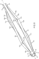
Figure 3 is a perspective view of the electrode assembly ofFigure 1 separated from the catheter, with a plurality of coextensive struts carrying the multiple electrodes; -
Figure 4 is a longitudinal cross-section of the electrode assembly ofFigure 3 ; -
Figure 5 is a perspective view similar toFigure 3 , with the electrodes, a tip and a coupling of the electrode assembly omitted; -
Figure 6 is a schematic view of the electrode assembly at one stage of manufacturing thereof at which the electrode assembly is in the form of a tube with portions of the tube cut away to form struts of the electrode assembly - the tube being in a longitudinally opened and laid flat orientation for illustrative purposes; -
Figure 7a is an enlarged schematic view of one strut of the electrode assembly ofFigure 6 ; -
Figure 7b is an enlarged schematic of a hinge of the strut ofFigure 7a ; -
Figure 8 is a perspective view similar toFigure 3 but with the electrode assembly illustrated in its expanded configuration; -
Figure 9 is a longitudinal cross-section of the electrode assembly ofFigure 8 ; -
Figure 10 is a perspective view of another embodiment of an electrode assembly for use with the catheter system ofFigure 1 ; and -
Figure 11 is a top plan view of one strut of the electrode assembly ofFigure 10 , with the strut laid flat for illustrative purposes. - Corresponding reference characters indicate corresponding parts throughout the several views of the drawings.
- Referring now to the drawings, and in particular to
Figures 1 and2 , one embodiment of acatheter system 21 includes aflexible catheter 23, ahandle 25 to which the catheter is connected, and aconductor assembly 27 for electrically connecting the catheter system to a suitable power supply (not shown). As one example, thecatheter system 21 illustrated and described herein is suitably constructed for use as an ablation system, such as a renal or heart ablation system. More particularly, the illustratedcatheter system 21 is a multi-electrode renal denervation system. One example of such acatheter system 21 is currently made by St. Jude Medical, Inc. under the trade name EnligHTN. General operation of a multi-electrode renal denervation system is known to those of skill in the art and is not described further herein except to the extent necessary to describe the present embodiments. It is also understood that thecatheter system 21 may be used for any other suitable treatment or purpose without departing from the scope of this disclosure. Additionally, while thecatheter system 21 is illustrated and described herein as including aflexible catheter 23, the system may further include other components used, for example, to guide the flexible catheter into the patient - such as, without limitation, a relatively more rigid guide catheter (not shown). - The
catheter 23 includes an elongate, flexiblehollow shaft 29 connected to thehandle 25 at or near a proximal or rear end of the catheter shaft (not shown because it is hidden by a connector at the front end of the handle 25), and anelectrode assembly 33 disposed at or near a distal orfront end 35 of the catheter shaft. It is understood, however, that theelectrode assembly 33 may be disposed anywhere along thecatheter shaft 29 intermediate the proximal end and thedistal end 35 thereof without departing from the scope of this disclosure. As used herein, the terms proximal and front, and distal and rear, are used with reference to the orientation of thecatheter system 21 illustrated in the various drawings and for the purpose of describing the various embodiments set forth herein, and are not intended as limiting the catheter system and related components to having any particular orientation upon assembly or during operation thereof. In particular, the terms proximal and rear refer to a longitudinal position that is relatively nearer to thehandle 25 while the terms distal and front refer to a longitudinal position that is relatively further from the handle. - The illustrated
electrode assembly 33 is in the form of what may be referred to as an electrode basket and is suitably configurable between a collapsed configuration (Figure 1 ) for maneuvering and positioning the electrode assembly in the patient, and an expanded configuration (Figure 3 ) for operation of the electrode assembly to perform a desired procedure such as an ablation procedure. An annular (e.g., ringshaped)actuator 37 is mounted on thehandle 25 for rotation relative thereto and is operatively connected to theelectrode assembly 33 for selectively configuring the electrode assembly between its collapsed and expanded configurations. It is understood that another suitable actuator (e.g., slide, push button, lever, etc.) may be used instead of the rotatingactuator 37 to selectively configure theelectrode assembly 33 without departing from the scope of this disclosure. In some embodiments, theelectrode assembly 33 may be selectively adjustable between an infinite number of configurations (e.g., degrees of expansion) between its collapsed and expanded configurations using theactuator 37. - A control line, such as a suitable cable or pull wire 41(
Fig. 3 ) extends from theelectrode assembly 33 within thehollow catheter shaft 29 and into thehandle 25 for operative connection with the actuator to thereby operatively connect theactuator 37 with the electrode assembly. In some embodiments two or more pull wires, cables or other suitable control lines may be used for selectively configuring theelectrode assembly 33. It is also understood that thecontrol line 41 may be any suitable control line other than a pull wire, such as a cable, string, tie, compression member or other suitable control to operatively connect theelectrode assembly 33 to theactuator 37. A suitable twisted electrical wire bundle (not shown) also extends through thehollow catheter shaft 29 from the handle to the electrode assembly to deliver power to the electrode assembly. - With reference now to
Figures 3 and4 , theelectrode assembly 33 has aproximal end 51 at which the assembly is connected to the catheter shaft 29 (e.g., to thedistal end 35 of the catheter shaft in the embodiment ofFigures 1 and2 ), adistal end 53 that in the illustrated embodiment also defines a distal end, or tip, of thecatheter 23, and a longitudinal axis X. The illustratedelectrode assembly 33 comprises a set of fourstruts 55a-d, extending coextensively with each other from theproximal end 51 to thedistal end 53 of the electrode assembly in circumferentially equal spaced relationship with each other about the longitudinal axis X of the electrode assembly. In other embodiments, theelectrode assembly 33 may comprise more or less than fourstruts 55a-d without departing from the scope of this disclosure. It is also contemplated that thestruts 55a-d may be other than equally spaced from each other circumferentially, and/or the struts may be other than coextensive with each other, and remain within the scope of this disclosure. - Each of the
struts 55a-d carries at least oneelectrode 57 disposed at a respective longitudinal position along the strut, i.e., at a respective longitudinal distance along the longitudinal axis X from the proximal end of the electrode assembly. In the embodiment ofFigure 3 , each of theelectrodes 57 is at a different longitudinal position. It is understood, however, that two, three or all of theelectrodes 57 may be at the same longitudinal position. It is also understood thatmultiple electrodes 57 may be carried by any one or all of thestruts 55a-d, e.g., with the electrodes on any given strut spaced longitudinally from each other along the strut. While not illustrated herein, one or more suitable sheathing or sleeves, constructed of a polymeric material, circumferentially enclose each of the struts along their respective lengths. The segment of thecontrol line 41 that extends from the proximal end to the distal end of the electrode assembly may likewise be circumferentially enclosed by a suitable polymeric sheathing or sleeve. - At the
distal end 53 of theelectrode assembly 33, thestruts 55a-d terminate at, and in one embodiment for making the electrode assembly (which is described in further detail later herein) are formed integrally with, a connectingring 61 having acentral opening 63 that is coaxial with the longitudinal axis X of the electrode assembly.Multiple holes 65 are formed in the sidewall of the connectingring 61 in spaced relationship with each other about the circumference of the connecting ring and are open to thecentral opening 63 of the connector. Suitable polymeric sheathing (not shown) may surround the connectingring 61 to cover theholes 65 following assembly of theelectrode assembly 33. As seen inFigures 3 and4 , ablunt tip 67 includes acylindrical body 69 having a longitudinal channel extending therethrough, and arounded head 71 formed integrally with the body at the longitudinally outer end of the body so as to close the longitudinal channel. - The
control line 41 extends generally along the longitudinal axis X of theelectrode assembly 33 into the longitudinal channel of thebody 69 of thetip 67 where it is secured to the tip by braising, adhesive, or other suitable securement technique. Thetip body 69 is sized in transverse cross-section, e.g., outer diameter, to be received through and seat within thecentral opening 63 of the connectingring 61 with thehead 71 of thetip 67 abutting against the end of the connecting ring. Theholes 65 spaced about the circumference of the connectingring 61 allow a suitable adhesive to be supplied through the holes for securing thetip 67 on the connecting ring - thereby connecting thedistal end 53 of theelectrode assembly 33 to thecontrol line 41 for operative connection with theactuator 37 on thehandle 25. In other embodiments thestruts 55a-d may be retained at thedistal end 53 of theelectrode assembly 33 in another suitable manner and remain within the scope of this disclosure. It is also contemplated that thestruts 55a-d and connectingring 61 may be formed separate from each other and subsequently secured together by any suitable securement technique. - At the
proximal end 51 of theelectrode assembly 33,longitudinal end segments 59 of thestruts 55a-d are connected to thecatheter shaft 29 by asuitable bushing 81. Thebushing 81 includes acylindrical body 83 having alongitudinal channel 85 through which thecontrol line 41 extends from thecatheter shaft 29 to theelectrode assembly 33. Anannular flange 87 extends radially outward from the longitudinally outer end of thebushing 81. Theflange 87 has four slots 89 (corresponding to the respectivelongitudinal end segments 59 of thestruts 55a-d) extending longitudinally therethrough radially outward of thecylindrical body 83 of thebushing 81 and in circumferentially spaced relationship with each other. As illustrated inFigure 4 , thelongitudinal end segments 59 of thestruts 55a-d extend through therespective slots 89 and along the outer surface of thecylindrical body 83 of thebushing 81. - The
body 83 of the bushing 81 (along with thelongitudinal end segments 59 of thestruts 55a-d) is fitted with apolyimide sleeve 91 filled with suitable adhesive to secure the sleeve and longitudinal end segments of the struts to the bushing. Thebushing 81, struts 55a-d andpolyimide sleeve 91 are inserted into thedistal end 35 of thehollow catheter shaft 29 and secured to the catheter shaft by suitable adhesive to secure theproximal end 51 of theelectrode assembly 33 to the distal end of the catheter shaft. It is understood that thestruts 55a-d may be connected to thecatheter shaft 29 by any other suitable connection that allows theelectrode assembly 33 to function in the manner described herein. - The
electrode assembly 33 thus has a length defined by the distance along the longitudinal axis X from theproximal end 51 to thedistal end 53 of the electrode assembly. To configure theelectrode assembly 33 from its collapsed configuration (e.g., as illustrated inFigures 1 ,3 and4 ) to its expanded configuration (e.g., as illustrated inFigures 2 ,8 and9 ), rotation of theactuator 37 relative to thehandle 25 operatively pulls on thecontrol wire 41 to thereby pull the tip (i.e., the distal end 53) of the electrode assembly toward theproximal end 51 of the electrode assembly along the longitudinal axis X thereof. As the distance between thedistal end 53 and theproximal end 51 of theelectrode assembly 33 is shortened (i.e., as the length of the electrode assembly decreases), thestruts 55a-d are longitudinally compressed and thus forced to bend, or flex transversely outward away from the longitudinal axis X of the electrode assembly to form the expanded configuration of the electrode assembly. As used herein, the expanded configuration of the electrode assembly refers to any transverse movement of thestruts 55a-d outward from the collapsed configuration of the electrode assembly, and may be variably adjusted. Accordingly, it is understood that in the expanded configuration theelectrode assembly 33 may be expanded more or less than as illustrated in the various embodiments herein. - In accordance with one embodiment, each of the
struts 55a-d has ahinge 101a-d adjacent therespective electrode 57 carried by the strut to facilitate bending of the strut at the hinge upon configuration of theelectrode assembly 33 toward its expanded configuration. This provides a predictable bending of thestruts 55a-d and thus a predictable and repeatable positioning of theelectrodes 57 in the expanded configuration of the electrode assembly. Because theelectrodes 57, (as discussed above and illustrated inFig. 3 ) are at different longitudinal positions along the length of theelectrode assembly 33, thehinges 101a-d for thestruts 55a-d are likewise at different longitudinal positions along the length of the electrode assembly. By facilitating bending of thestruts 55a-d at therespective hinges 101a-d, in the expanded configuration of theelectrode assembly 33 the hinge of each strut is transversely spaced from the longitudinal axis X a distance greater than any other point or segment along the strut. Thus, it will be understood that for eachstrut 55a-d thehinge 101a-d allows theelectrode 57 carried by the strut to be positioned transversely outward away from the longitudinal axis X as much as possible in the expanded configuration of theelectrode assembly 33, irrespective of the longitudinal position of the electrode relative to theproximal end 51 of the electrode assembly. - With reference to
Figure 6 solely for purposes of describing the configuration of each of thestruts 55a-d, each strut includes a respectivelonger leg 103a-d and ashorter leg 105a-d - with therespective hinge 101a-d of the strut being disposed at the junction of the longer leg with the shorter leg. In the illustrated embodiment, for example, thetopmost strut 55a inFigure 6 has thelonger leg 103a extending from theproximal end 51 of theelectrode assembly 33 to thehinge 101a for that strut, and theshorter leg 105a extending from thedistal end 53 of the electrode assembly to the hinge. Thestrut 55b that in theelectrode assembly 33 is circumferentially adjacent to thestrut 55a has thelonger leg 103b extending from thedistal end 53 of theelectrode assembly 33 to thehinge 101b for that strut and theshorter leg 105b extending from theproximal end 51 of the electrode assembly to the hinge. - Thus, it will be seen in the embodiment of
Figures 3-9 that thestruts 55a-d circumferentially alternate which of the longer orshorter legs 103a-d, 105a-d extends from theproximal end 51 of theelectrode assembly 33. This facilitates thestruts 55a-d being capable of closely spaced relationship with each other upon compressing down of the electrode assembly 33 (e.g., from its collapsed configuration) as thecatheter 23 is guided through the vasculature of the patient. It is understood, however, that thestruts 55a-d may be arranged circumferentially about theelectrode assembly 33 in any arrangement of which of thelonger legs 103a-d orshorter legs 105a-d extend from theproximal end 51 of the electrode assembly. It is also contemplated that in other embodiments thelonger legs 103a-d of thestruts 55a-d may all extend from theproximal end 51 of theelectrode assembly 33, or all extend from thedistal end 53 of the electrode assembly, without departing from the scope of this disclosure. As illustrated inFigure 3 , theelectrodes 57 carried by thestruts 55a-d are each disposed on thelonger legs 103a-d of the struts adjacent therespective hinge 101a-d. For example, in one embodiment the electrodes are disposed on thelonger legs 103a-d of thestruts 55a-d within about 0.03 inches (0.762 mm) of therespective hinge 101a-d. - With reference to
Figs. 7a and 7b , which illustrates thetopmost strut 55a of theelectrode assembly 33 ofFigure 6 , thelonger leg 103a-d of each strut has a width that decreases continuously (e.g., narrows) from afirst end 111 adjacent thehinge 101a of the strut to asecond end 113 opposite the first end. For example, thelonger leg 103a of thestrut 55a ofFigure 7a has a width WL1 adjacent thehinge 101a and tapers down to a narrower width WL2 at theopposite end 113 adjacent theproximal end 51 of theelectrode assembly 33. Theshorter leg 105a of eachstrut 55a also has a width that decreases continuously from afirst end 115 adjacent thehinge 101a of the strut to asecond end 117 opposite the first end. For thestrut 55a ofFigure 7a , theshorter leg 105a has a width WS1 adjacent thehinge 101a and tapers to a narrower width WS2 at theopposite end 117 adjacent thedistal end 53 of theelectrode assembly 33. The larger width WS1 of theshorter leg 105a (e.g. adjacent thehinge 101a) is substantially equal to the larger width WL1 of thelonger leg 103a. In contrast, the smaller width WS2 of theshorter leg 105a is substantially less than the smaller width WL2 of thelonger leg 103a. Thus, it will be understood that the width of theshorter leg 105a narrows more rapidly along its length than does the width of thelonger leg 103a, and the shorter leg narrows down to a smaller width than does the longer leg. - Each strut (as illustrated on the
strut 55a inFigure 7b ) has a substantially narrowed width Wz to define thehinge 101a of the strut. As used herein, the width Wz of thestrut 55a-d at thehinge 101a-d is defined as a reduced total width of the strut material transversely across the strut. For example, with reference to thehinge 101a of thestrut 55a ofFigure 7b , eachhinge 101a has U-shaped cut-outs on opposite sides of the respective strut so that the strut material is continuous across along a narrowed width Wz of the hinge. The rounded contour of each of the cut-outs reduces the stress at thehinge 101a upon bending of thestrut 55a. In other embodiments, the cut-outs may be other than U-shaped, such as V-shaped or other suitable shape and remain within the scope of this disclosure. It is also understood that thehinge 101a may alternatively be formed by cutting an opening (not shown) between the side edges of thestrut 55a at the hinge so that the narrowed width Wz of the strut at the hinge is defined by the combined widths of the webs of strut material remaining on both sides of the opening. - In one example, for the
struts 55a-d of theelectrode assembly 33 illustrated inFigures 3-9 , each of thelonger legs 103a-d has a width WL1 (as illustrated inFigures 7a and 7b ) adjacent therespective hinge 101a-d of about 0.03 inches (0.762 mm). Each of theshorter legs 105a-d has a width WS1 adjacent thehinge 101a-d that is approximately equal to the width WL1 of thelonger leg 103a-d. The width Wz (as illustrated inFigure 7b ) of eachstrut 55a-d at therespective hinge 101a-d is about 0.01 inches. Additionally, the width of thelonger leg 103a-d at theend 113 away from thehinge 101a-d is about 0.02 inches (0.508 mm), while the width of theshorter leg 105a-d at theend 117 away from the hinge is about 0.01 inches (0.254 mm). It is understood, however, that the relative widths of thelonger legs 103a-d, theshorter legs 105a-d and/or thehinges 101a-d may be other than as set forth above and remain within the scope of this disclosure. - In one exemplary embodiment for making the
electrode assembly 33 ofFigures 3-9 , aunitary tube 121 of a material having sufficient strength and shape memory characteristics, such as Nitinol , is used. The illustratedtube 121, as an example, has an outer diameter of about 0.0505 inches and an inner diameter of about 0.042 inches. However, the dimensions of thetube 121 as well as the material or materials from which it is constructed may be other than as set forth above and remain with the scope of this disclosure. The desired pattern ofstruts 55a-d is then laser cut into thetube 121. - The
tube 121 is initially longer than the length of the finished electrode assembly 33 (as illustrated inFigure 3 ). For example, theelectrode assembly 33 illustrated inFigure 6 is representative of the tube 121 (although cut lengthwise and laid flat) as initially formed. In the illustrated embodiment, an initial slight amount of preset bend at therespective hinges 101a-d - is formed in thetube 121 following laser cutting using an internal and external die assembly and then heat set to give the tube its shape memory. Additional preset bending may be heat set into thestruts 55a-d adjacent the proximal and/ or distal ends 51, 53 of theelectrode assembly 33 to further facilitate predictable bending of the struts into their desired configurations in the expanded configuration of the electrode assembly. - As further illustrated in
Figure 6 , analignment member 123 is formed on eachstrut 55a-d during the laser cutting process longitudinally outward of the ends of the struts near what eventually becomes theproximal end 51 of theelectrode assembly 33. Following the heat setting, thetube 21 is cut adjacent thealignment members 123 to define thelongitudinal end segments 59 of thestruts 55a-d for connecting the struts to thebushing 81 and subsequently to thecatheter shaft 29 in the manner described previously. Thetip 67 is secured to thedistal end 53 of the electrode assembly 33 (e.g., to the connecting ring 61) in the manner described previously. -
Figures 10 and11 illustrate another embodiment of anelectrode assembly 133 suitable for use with a catheter system such as thecatheter system 21 illustrated inFigures 1 and2 . In this embodiment, thelonger legs 203a-d of each of thestruts 155a-d are configured to be similar to thelonger legs 103a-d of thestruts 55a-d ofFigs. 3-9 in that the width WL1 of each longer leg is greater adjacent thehinge 201a-d than the width WL2 at its end opposite the hinge. In this embodiment, thelonger leg 203a-d may be shaped slightly different adjacent thehinge 201a-d than thelonger leg 103a-d of eachstrut 55a-d of the previous embodiment. Alternatively, thelonger leg 203a-d adjacent thehinge 201a-d may be shaped substantially the same as thelonger leg 103a-d of eachstrut 55a-d of the previous embodiment, or it may be shaped in any other manner that allows the struts to function in the manner described herein. Theshorter leg 205a-d of eachstrut 155a-d is configured to have a uniform width WS1, WS2 along its length, including adjacent thehinge 201a-d. For example, in the illustrated embodiment the width WS1 of theshorter leg 205a-d adjacent thehinge 201a-d is equal to the width Wz of thestrut 155a-d at the hinge. - Although certain embodiments of this disclosure have been described above with a certain degree of particularity, those skilled in the art could make numerous alterations to the disclosed embodiments without departing from the scope of this disclosure. All directional references (e.g., upper, lower, upward, downward, left, right, leftward, rightward, top, bottom, above, below, vertical, horizontal, clockwise, and counterclockwise) are only used for identification purposes to aid the reader's understanding of the present disclosure, and do not create limitations, particularly as to the position, orientation, or use of the disclosure. Joinder references (e.g., attached, coupled, connected, and the like) are to be construed broadly and may include intermediate members between a connection of elements and relative movement between elements. As such, joinder references do not necessarily infer that two elements are directly connected and in fixed relation to each other. It is intended that all matter contained in the above description or shown in the accompanying drawings shall be interpreted as illustrative only and not limiting. Changes in detail or structure may be made without departing from the disclosure as defined in the appended claims.
Claims (4)
- An electrode assembly (33) for an electrode catheter system, the electrode assembly (33) having a longitudinal axis (X), a proximal end (51) and a distal end (53), the electrode assembly (33) comprising:a plurality of struts (55) extending coextensively with each other from the proximal end (51) to the distal end (53) of the electrode assembly (33), each strut having a corresponding electrode disposed thereon and spaced longitudinally from the proximal end (51) of the electrode assembly (33), the longitudinal spacing of one of the electrodes from the proximal end (51) of the electrode assembly (33) being different from the longitudinal spacing of at least another one of the electrodes from the proximal end (51) of the electrode assembly (33);each strut comprises a longer leg (103) and a shorter leg (105), the hinge (100) of the strut being intermediate the longer leg (103) and the shorter leg (105), the longer leg (103) of at least one of the struts extending from the proximal end (51) of the electrode assembly (33) to the hinge (100) and the shorter leg (105) of said at least one of the struts extending from the distal end (53) of the electrode assembly (33) to the hinge (100);the struts (55) circumferentially alternate which of the longer or shorter legs (103, 105) extends from the proximal end (51) of the electrode assembly (33) to facilitate the struts (55) being capable of a closely spaced relationship with each other upon compressing down of the electrode assembly (33);wherein the electrode assembly (33) is configurable between a collapsed configuration and an expanded configuration, the electrodes being transversely spaced from the longitudinal axis of the electrode assembly (33) a greater distance in the expanded configuration than in the collapsed configuration, in the expanded configuration, the electrodes being transversely spaced from the longitudinal axis (X) of the electrode assembly (33) approximately the same distance.
- The electrode assembly (33) of claim 1 wherein the longitudinal spacing of each electrode from the proximal end (51) of the electrode assembly (33) is different from the longitudinal spacing of each other electrode from the proximal end (51) of the electrode assembly (33).
- The electrode assembly (33) of claim 1 wherein each of the struts (55) is configured to facilitate bending of the strut within about 0.03 inches (0.762 mm) the longitudinal position of the corresponding electrode disposed on the strut.
- The electrode assembly (33) of claim 1 wherein the electrode assembly (33) has a length from its proximal end (51) to its distal end (53), the length of the electrode assembly (33) decreasing upon configuring of the electrode assembly (33) from its collapsed configuration to its expanded configuration.
Applications Claiming Priority (2)
| Application Number | Priority Date | Filing Date | Title |
|---|---|---|---|
| US201361816043P | 2013-04-25 | 2013-04-25 | |
| PCT/US2014/034898 WO2014176205A1 (en) | 2013-04-25 | 2014-04-22 | Electrode assembly for catheter system |
Publications (2)
| Publication Number | Publication Date |
|---|---|
| EP2988691A1 EP2988691A1 (en) | 2016-03-02 |
| EP2988691B1 true EP2988691B1 (en) | 2018-03-28 |
Family
ID=50829276
Family Applications (1)
| Application Number | Title | Priority Date | Filing Date |
|---|---|---|---|
| EP14726829.6A Not-in-force EP2988691B1 (en) | 2013-04-25 | 2014-04-22 | Electrode assembly for catheter system |
Country Status (3)
| Country | Link |
|---|---|
| US (1) | US10350002B2 (en) |
| EP (1) | EP2988691B1 (en) |
| WO (1) | WO2014176205A1 (en) |
Families Citing this family (40)
| Publication number | Priority date | Publication date | Assignee | Title |
|---|---|---|---|---|
| US8150519B2 (en) | 2002-04-08 | 2012-04-03 | Ardian, Inc. | Methods and apparatus for bilateral renal neuromodulation |
| JP5219518B2 (en) | 2004-12-09 | 2013-06-26 | ザ ファウンドリー, エルエルシー | Aortic valve repair |
| US20150011991A1 (en) | 2013-07-03 | 2015-01-08 | St. Jude Medical, Cardiology Division, Inc. | Electrode Assembly For Catheter System |
| US9579149B2 (en) | 2014-03-13 | 2017-02-28 | Medtronic Ardian Luxembourg S.A.R.L. | Low profile catheter assemblies and associated systems and methods |
| US10058695B2 (en) | 2014-12-18 | 2018-08-28 | Medtronic, Inc. | Collapsible extravascular lead |
| US9782099B2 (en) | 2014-12-31 | 2017-10-10 | Biosense Webster (Israel) Ltd. | Basket catheter with improved spine flexibility |
| US10905329B2 (en) | 2016-06-09 | 2021-02-02 | Biosense Webster (Israel) Ltd. | Multi-function conducting elements for a catheter |
| US10391299B2 (en) | 2017-03-30 | 2019-08-27 | Medtronic, Inc. | Interventional medical systems for therapy delivery in extracardiovascular spaces and associated tools and methods |
| US12029545B2 (en) | 2017-05-30 | 2024-07-09 | Biosense Webster (Israel) Ltd. | Catheter splines as location sensors |
| US20190314083A1 (en) | 2018-04-11 | 2019-10-17 | Biosense Webster (Israel) Ltd. | Flexible Multi-Arm Catheter with Diametrically Opposed Sensing Electrodes |
| US11045628B2 (en) | 2018-12-11 | 2021-06-29 | Biosense Webster (Israel) Ltd. | Balloon catheter with high articulation |
| US11207016B2 (en) | 2018-12-28 | 2021-12-28 | Biosense Webster (Israel) Ltd. | Mapping ECG signals using a multipole electrode assembly |
| US11850051B2 (en) | 2019-04-30 | 2023-12-26 | Biosense Webster (Israel) Ltd. | Mapping grid with high density electrode array |
| US11712172B2 (en) | 2019-07-18 | 2023-08-01 | Biosense Webster (Israel) Ltd. | Visual guidance for positioning a distal end of a medical probe |
| US11759150B2 (en) | 2019-08-27 | 2023-09-19 | Biosense Webster (Israel) Ltd. | Accurate basket catheter tracking |
| WO2021111361A1 (en) * | 2019-12-04 | 2021-06-10 | Hyblate Medical Ltd. | Cardiac tissue ablation device |
| US11950930B2 (en) | 2019-12-12 | 2024-04-09 | Biosense Webster (Israel) Ltd. | Multi-dimensional acquisition of bipolar signals from a catheter |
| US11517218B2 (en) | 2019-12-20 | 2022-12-06 | Biosense Webster (Israel) Ltd. | Selective graphical presentation of electrophysiological parameters |
| US12232874B2 (en) | 2020-05-29 | 2025-02-25 | Biosense Webster (Israel) Ltd. | Electrode apparatus for diagnosis of arrhythmias |
| US11987017B2 (en) | 2020-06-08 | 2024-05-21 | Biosense Webster (Israel) Ltd. | Features to assist in assembly and testing of devices |
| US12048479B2 (en) | 2020-09-10 | 2024-07-30 | Biosense Webster (Israel) Ltd. | Surface mounted electrode catheter |
| US11950841B2 (en) | 2020-09-22 | 2024-04-09 | Biosense Webster (Israel) Ltd. | Basket catheter having insulated ablation electrodes and diagnostic electrodes |
| US11950840B2 (en) | 2020-09-22 | 2024-04-09 | Biosense Webster (Israel) Ltd. | Basket catheter having insulated ablation electrodes |
| US12082875B2 (en) | 2020-09-24 | 2024-09-10 | Biosense Webster (Israel) Ltd | Balloon catheter having a coil for sensing tissue temperature and position of the balloon |
| US12201786B2 (en) | 2020-12-17 | 2025-01-21 | Biosense Webster (Israel) Ltd. | Measurement of distal end dimension of catheters using magnetic fields |
| US11918383B2 (en) | 2020-12-21 | 2024-03-05 | Biosense Webster (Israel) Ltd. | Visualizing performance of catheter electrodes |
| US12064170B2 (en) | 2021-05-13 | 2024-08-20 | Biosense Webster (Israel) Ltd. | Distal assembly for catheter with lumens running along spines |
| CN113470896B (en) * | 2021-07-09 | 2022-08-16 | 西北工业大学 | Method for integrating extensible stimulation electrode on surface of semi-inflatable micro-balloon |
| US12364426B2 (en) | 2021-08-12 | 2025-07-22 | Biosense Webster (Israel) Ltd. | Electro-anatomical mapping and annotation presented in electrophysiological procedures |
| US12004804B2 (en) | 2021-09-09 | 2024-06-11 | Biosense Webster (Israel) Ltd. | Basket catheter with mushroom shape distal tip |
| US12478424B2 (en) | 2021-09-10 | 2025-11-25 | Biosense Webster (Israel) Ltd. | Staggered pairs of biased ablation electrodes on basket catheter |
| US12011280B2 (en) | 2021-10-04 | 2024-06-18 | Biosense Webster (Israel) Ltd. | Electrophysiological mapping in the presence of injury current |
| US12533489B2 (en) | 2021-10-08 | 2026-01-27 | Biosense Webster (Israel) Ltd. | Measuring tissue proximity for multi-electrode catheter |
| US12419683B2 (en) | 2021-12-22 | 2025-09-23 | Biosense Webster (Israel) Ltd. | Irreversible electroporation with shorted electrodes |
| US12484961B2 (en) | 2022-01-20 | 2025-12-02 | Biosense Webster (Israel) Ltd. | Mechanical retainer systems for electrodes of a basket catheter, and methods of the same |
| US12446946B2 (en) | 2022-01-20 | 2025-10-21 | Biosense Webster (Israel) Ltd. | Systems and methods for a single spiral electrode assembly forming a spherical basket for improved tissue contact and current delivery |
| US12440263B2 (en) | 2022-01-20 | 2025-10-14 | Biosense Webster (Israel) Ltd. | Systems and methods for tripodic spines forming a spherical basket for improved tissue contact and current delivery |
| US12471989B2 (en) | 2022-04-28 | 2025-11-18 | Biosense Webster (Israel) Ltd. | Strengthened expandable baskets for medical probes and medical probes containing strengthen expandable baskets |
| US12533185B2 (en) | 2022-12-28 | 2026-01-27 | Biosense Webster (Israel) Ltd. | Basket end effector with distal position sensor |
| US12521035B2 (en) | 2022-12-29 | 2026-01-13 | Biosense Webster (Israel) Ltd. | Cylindrical cage systems and methods for distributed tissue contact for mapping and ablation |
Family Cites Families (114)
| Publication number | Priority date | Publication date | Assignee | Title |
|---|---|---|---|---|
| SE346468B (en) | 1969-02-24 | 1972-07-10 | Lkb Medical Ab | |
| US4658819A (en) | 1983-09-13 | 1987-04-21 | Valleylab, Inc. | Electrosurgical generator |
| US4955377A (en) | 1988-10-28 | 1990-09-11 | Lennox Charles D | Device and method for heating tissue in a patient's body |
| US5749914A (en) | 1989-01-06 | 1998-05-12 | Advanced Coronary Intervention | Catheter for obstructed stent |
| US5035694A (en) | 1989-05-15 | 1991-07-30 | Advanced Cardiovascular Systems, Inc. | Dilatation catheter assembly with heated balloon |
| US5465717A (en) | 1991-02-15 | 1995-11-14 | Cardiac Pathways Corporation | Apparatus and Method for ventricular mapping and ablation |
| US5300068A (en) | 1992-04-21 | 1994-04-05 | St. Jude Medical, Inc. | Electrosurgical apparatus |
| US5255679A (en) | 1992-06-02 | 1993-10-26 | Cardiac Pathways Corporation | Endocardial catheter for mapping and/or ablation with an expandable basket structure having means for providing selective reinforcement and pressure sensing mechanism for use therewith, and method |
| US5772590A (en) | 1992-06-30 | 1998-06-30 | Cordis Webster, Inc. | Cardiovascular catheter with laterally stable basket-shaped electrode array with puller wire |
| US5411025A (en) | 1992-06-30 | 1995-05-02 | Cordis Webster, Inc. | Cardiovascular catheter with laterally stable basket-shaped electrode array |
| US8728065B2 (en) | 2009-07-02 | 2014-05-20 | St. Jude Medical, Atrial Fibrillation Division, Inc. | Apparatus and methods for contactless electrophysiology studies |
| AU5295493A (en) | 1992-10-01 | 1994-04-26 | Cardiac Pacemakers, Inc. | Stent-type defibrillation electrode structures |
| US5387233A (en) | 1993-01-11 | 1995-02-07 | Incontrol, Inc. | Intravenous cardiac lead with improved fixation and method |
| US6161543A (en) | 1993-02-22 | 2000-12-19 | Epicor, Inc. | Methods of epicardial ablation for creating a lesion around the pulmonary veins |
| US5893847A (en) | 1993-03-16 | 1999-04-13 | Ep Technologies, Inc. | Multiple electrode support structures with slotted hub and hoop spline elements |
| US6233491B1 (en) | 1993-03-16 | 2001-05-15 | Ep Technologies, Inc. | Cardiac mapping and ablation systems |
| DE69432148T2 (en) | 1993-07-01 | 2003-10-16 | Boston Scientific Ltd., St. Michael | CATHETER FOR IMAGE DISPLAY, DISPLAY OF ELECTRICAL SIGNALS AND ABLATION |
| US5607462A (en) | 1993-09-24 | 1997-03-04 | Cardiac Pathways Corporation | Catheter assembly, catheter and multi-catheter introducer for use therewith |
| US5911739A (en) * | 1994-03-04 | 1999-06-15 | Ep Technologies, Inc. | Structures for supporting diagnostic or therapeutic elements in internal body regions |
| US5598848A (en) | 1994-03-31 | 1997-02-04 | Ep Technologies, Inc. | Systems and methods for positioning multiple electrode structures in electrical contact with the myocardium |
| US5897553A (en) | 1995-11-02 | 1999-04-27 | Medtronic, Inc. | Ball point fluid-assisted electrocautery device |
| US5676662A (en) | 1995-03-17 | 1997-10-14 | Daig Corporation | Ablation catheter |
| US5707400A (en) | 1995-09-19 | 1998-01-13 | Cyberonics, Inc. | Treating refractory hypertension by nerve stimulation |
| US6283951B1 (en) | 1996-10-11 | 2001-09-04 | Transvascular, Inc. | Systems and methods for delivering drugs to selected locations within the body |
| US6073048A (en) | 1995-11-17 | 2000-06-06 | Medtronic, Inc. | Baroreflex modulation with carotid sinus nerve stimulation for the treatment of heart failure |
| SE9504675D0 (en) | 1995-12-28 | 1995-12-28 | Pacesetter Ab | Implantable electrode cable assembly with multiple electrode contact elements |
| US6036687A (en) | 1996-03-05 | 2000-03-14 | Vnus Medical Technologies, Inc. | Method and apparatus for treating venous insufficiency |
| US6016437A (en) | 1996-10-21 | 2000-01-18 | Irvine Biomedical, Inc. | Catheter probe system with inflatable soft shafts |
| US5893885A (en) | 1996-11-01 | 1999-04-13 | Cordis Webster, Inc. | Multi-electrode ablation catheter |
| US5954719A (en) | 1996-12-11 | 1999-09-21 | Irvine Biomedical, Inc. | System for operating a RF ablation generator |
| US6012457A (en) | 1997-07-08 | 2000-01-11 | The Regents Of The University Of California | Device and method for forming a circumferential conduction block in a pulmonary vein |
| US6024740A (en) | 1997-07-08 | 2000-02-15 | The Regents Of The University Of California | Circumferential ablation device assembly |
| US6117101A (en) | 1997-07-08 | 2000-09-12 | The Regents Of The University Of California | Circumferential ablation device assembly |
| US6500174B1 (en) | 1997-07-08 | 2002-12-31 | Atrionix, Inc. | Circumferential ablation device assembly and methods of use and manufacture providing an ablative circumferential band along an expandable member |
| US6096037A (en) | 1997-07-29 | 2000-08-01 | Medtronic, Inc. | Tissue sealing electrosurgery device and methods of sealing tissue |
| US6200312B1 (en) | 1997-09-11 | 2001-03-13 | Vnus Medical Technologies, Inc. | Expandable vein ligator catheter having multiple electrode leads |
| US5954649A (en) | 1997-10-20 | 1999-09-21 | Irvine Biomedical, Inc. | Catheter system having ultrasound locating capabilities |
| US6699231B1 (en) | 1997-12-31 | 2004-03-02 | Heartport, Inc. | Methods and apparatus for perfusion of isolated tissue structure |
| US6358245B1 (en) | 1998-02-19 | 2002-03-19 | Curon Medical, Inc. | Graphical user interface for association with an electrode structure deployed in contact with a tissue region |
| US6423058B1 (en) | 1998-02-19 | 2002-07-23 | Curon Medical, Inc. | Assemblies to visualize and treat sphincters and adjoining tissue regions |
| WO1999055245A1 (en) * | 1998-04-30 | 1999-11-04 | Edwards Stuart D | Electrosurgical sphincter treatment apparatus |
| US7198635B2 (en) | 2000-10-17 | 2007-04-03 | Asthmatx, Inc. | Modification of airways by application of energy |
| US6292695B1 (en) | 1998-06-19 | 2001-09-18 | Wilton W. Webster, Jr. | Method and apparatus for transvascular treatment of tachycardia and fibrillation |
| US6322559B1 (en) | 1998-07-06 | 2001-11-27 | Vnus Medical Technologies, Inc. | Electrode catheter having coil structure |
| US7313444B2 (en) | 1998-11-20 | 2007-12-25 | Pacesetter, Inc. | Self-anchoring coronary sinus lead |
| US7481803B2 (en) | 2000-11-28 | 2009-01-27 | Flowmedica, Inc. | Intra-aortic renal drug delivery catheter |
| US6178349B1 (en) | 1999-04-15 | 2001-01-23 | Medtronic, Inc. | Drug delivery neural stimulation device for treatment of cardiovascular disorders |
| WO2001000273A1 (en) | 1999-06-25 | 2001-01-04 | Emory University | Devices and methods for vagus nerve stimulation |
| EP1244392A1 (en) | 1999-09-28 | 2002-10-02 | Novasys Medical, Inc. | Treatment of tissue by application of energy and drugs |
| US6669655B1 (en) | 1999-10-20 | 2003-12-30 | Transurgical, Inc. | Sonic element and catheter incorporating same |
| US6287608B1 (en) | 2000-04-11 | 2001-09-11 | Intellicardia, Inc. | Method and apparatus for treatment of congestive heart failure by improving perfusion of the kidney by infusion of a vasodilator |
| CA2415671C (en) | 2000-07-13 | 2011-02-01 | Transurgical, Inc. | Energy application with inflatable annular lens |
| WO2002005868A2 (en) | 2000-07-13 | 2002-01-24 | Transurgical, Inc. | Thermal treatment methods and apparatus with focused energy application |
| US6656174B1 (en) | 2000-07-20 | 2003-12-02 | Scimed Life Systems, Inc. | Devices and methods for creating lesions in blood vessels without obstructing blood flow |
| US6985774B2 (en) | 2000-09-27 | 2006-01-10 | Cvrx, Inc. | Stimulus regimens for cardiovascular reflex control |
| US6522926B1 (en) | 2000-09-27 | 2003-02-18 | Cvrx, Inc. | Devices and methods for cardiovascular reflex control |
| US6845267B2 (en) | 2000-09-28 | 2005-01-18 | Advanced Bionics Corporation | Systems and methods for modulation of circulatory perfusion by electrical and/or drug stimulation |
| US6616624B1 (en) | 2000-10-30 | 2003-09-09 | Cvrx, Inc. | Systems and method for controlling renovascular perfusion |
| US6564096B2 (en) | 2001-02-28 | 2003-05-13 | Robert A. Mest | Method and system for treatment of tachycardia and fibrillation |
| US7097651B2 (en) | 2001-09-06 | 2006-08-29 | Advanced Cardiovascular Systems, Inc. | Embolic protection basket |
| US8974446B2 (en) | 2001-10-11 | 2015-03-10 | St. Jude Medical, Inc. | Ultrasound ablation apparatus with discrete staggered ablation zones |
| US6748255B2 (en) | 2001-12-14 | 2004-06-08 | Biosense Webster, Inc. | Basket catheter with multiple location sensors |
| US6741878B2 (en) | 2001-12-14 | 2004-05-25 | Biosense Webster, Inc. | Basket catheter with improved expansion mechanism |
| US7155284B1 (en) | 2002-01-24 | 2006-12-26 | Advanced Bionics Corporation | Treatment of hypertension |
| US6733499B2 (en) | 2002-02-28 | 2004-05-11 | Biosense Webster, Inc. | Catheter having circular ablation assembly |
| AU2003212640A1 (en) | 2002-03-14 | 2003-09-22 | Brainsgate Ltd. | Technique for blood pressure regulation |
| JP4295627B2 (en) | 2002-03-27 | 2009-07-15 | シーブイアールエックス, インコーポレイテッド | Electrode structure and its use in controlling circulatory system reflection |
| US7653438B2 (en) | 2002-04-08 | 2010-01-26 | Ardian, Inc. | Methods and apparatus for renal neuromodulation |
| US7162303B2 (en) | 2002-04-08 | 2007-01-09 | Ardian, Inc. | Renal nerve stimulation method and apparatus for treatment of patients |
| US20070135875A1 (en) | 2002-04-08 | 2007-06-14 | Ardian, Inc. | Methods and apparatus for thermally-induced renal neuromodulation |
| US8347891B2 (en) | 2002-04-08 | 2013-01-08 | Medtronic Ardian Luxembourg S.A.R.L. | Methods and apparatus for performing a non-continuous circumferential treatment of a body lumen |
| US7617005B2 (en) | 2002-04-08 | 2009-11-10 | Ardian, Inc. | Methods and apparatus for thermally-induced renal neuromodulation |
| US8145316B2 (en) | 2002-04-08 | 2012-03-27 | Ardian, Inc. | Methods and apparatus for renal neuromodulation |
| US7756583B2 (en) | 2002-04-08 | 2010-07-13 | Ardian, Inc. | Methods and apparatus for intravascularly-induced neuromodulation |
| EP1605875A3 (en) | 2003-03-03 | 2005-12-28 | Sinus Rhythm Technologies, Inc. | Electrical block positioning devices and methods of use therefor |
| US7149574B2 (en) | 2003-06-09 | 2006-12-12 | Palo Alto Investors | Treatment of conditions through electrical modulation of the autonomic nervous system |
| DE202004021946U1 (en) | 2003-09-12 | 2013-05-29 | Vessix Vascular, Inc. | Selectable eccentric remodeling and / or ablation of atherosclerotic material |
| US8343213B2 (en) | 2003-12-23 | 2013-01-01 | Sadra Medical, Inc. | Leaflet engagement elements and methods for use thereof |
| US7245955B2 (en) | 2004-02-23 | 2007-07-17 | St. Jude Medical, Atrial Fibrillation Division, Inc. | Electrophysiology/ablation catheter having deflection assembly |
| US7949407B2 (en) | 2004-11-05 | 2011-05-24 | Asthmatx, Inc. | Energy delivery devices and methods |
| US7468062B2 (en) | 2004-11-24 | 2008-12-23 | Ablation Frontiers, Inc. | Atrial ablation catheter adapted for treatment of septal wall arrhythmogenic foci and method of use |
| EP2438877B1 (en) | 2005-03-28 | 2016-02-17 | Vessix Vascular, Inc. | Intraluminal electrical tissue characterization and tuned RF energy for selective treatment of atheroma and other target tissues |
| US7419486B2 (en) | 2005-06-15 | 2008-09-02 | St. Jude Medical, Atrial Fibrillation Division, Inc. | Treatment and diagnostic catheters with hydrogel electrodes |
| EP2759276A1 (en) | 2005-06-20 | 2014-07-30 | Medtronic Ablation Frontiers LLC | Ablation catheter |
| US7465288B2 (en) | 2005-06-28 | 2008-12-16 | St. Jude Medical, Atrial Fibrillation Division, Inc. | Actuation handle for a catheter |
| US20070299435A1 (en) | 2006-06-23 | 2007-12-27 | Crowe John E | Apparatus and method for ablating tissue |
| CN105056408B (en) | 2006-06-28 | 2018-09-25 | 美敦力Af卢森堡公司 | The system that renal nerve for thermal induction is modulated |
| US8442639B2 (en) | 2007-02-13 | 2013-05-14 | Cardiac Pacemakers, Inc. | Systems and methods for electrical stimulation of blood vessels |
| US10183183B2 (en) | 2007-04-13 | 2019-01-22 | Acoustic Medsystems, Inc. | Acoustic applicators for controlled thermal modification of tissue |
| EP2139416B1 (en) | 2007-05-09 | 2015-08-19 | Irvine Biomedical, Inc. | Basket catheter having multiple electrodes |
| US8588885B2 (en) | 2007-05-09 | 2013-11-19 | St. Jude Medical, Atrial Fibrillation Division, Inc. | Bendable catheter arms having varied flexibility |
| US11395694B2 (en) | 2009-05-07 | 2022-07-26 | St. Jude Medical, Llc | Irrigated ablation catheter with multiple segmented ablation electrodes |
| WO2008151001A2 (en) | 2007-05-30 | 2008-12-11 | The Cleveland Clinic Foundation | Method for treating a renal disease or disorder |
| US10363057B2 (en) | 2008-07-18 | 2019-07-30 | Vytronus, Inc. | System and method for delivering energy to tissue |
| WO2010042869A1 (en) | 2008-10-10 | 2010-04-15 | Intervalve, Inc. | Valvuloplasty catheter and methods |
| US8712550B2 (en) | 2008-12-30 | 2014-04-29 | Biosense Webster, Inc. | Catheter with multiple electrode assemblies for use at or near tubular regions of the heart |
| US8808345B2 (en) | 2008-12-31 | 2014-08-19 | Medtronic Ardian Luxembourg S.A.R.L. | Handle assemblies for intravascular treatment devices and associated systems and methods |
| JP6013186B2 (en) * | 2009-11-13 | 2016-10-25 | セント ジュード メディカル インコーポレイテッド | Staggered arrangement of shochu elements |
| US9907607B2 (en) | 2009-12-30 | 2018-03-06 | St. Jude Medical, Atrial Fibrillation Division, Inc. | Guide and flexible sleeve for use with catheters |
| US20110257641A1 (en) | 2010-04-14 | 2011-10-20 | Roger Hastings | Phototherapy for renal denervation |
| US20110264086A1 (en) | 2010-04-14 | 2011-10-27 | Frank Ingle | Renal artery denervation apparatus employing helical shaping arrangement |
| US8870863B2 (en) | 2010-04-26 | 2014-10-28 | Medtronic Ardian Luxembourg S.A.R.L. | Catheter apparatuses, systems, and methods for renal neuromodulation |
| US9585587B2 (en) | 2010-11-09 | 2017-03-07 | St. Judge Medical, Atrial Fibrillation Division, Inc. | Fixed loop deflectable electrophysiology catheters having an extended braid primary shaft coupled to the periphery of the fixed loop and methods of manufacturing therefor |
| US8560086B2 (en) | 2010-12-02 | 2013-10-15 | St. Jude Medical, Atrial Fibrillation Division, Inc. | Catheter electrode assemblies and methods of construction therefor |
| US10016233B2 (en) | 2010-12-06 | 2018-07-10 | Biosense Webster (Israel) Ltd. | Treatment of atrial fibrillation using high-frequency pacing and ablation of renal nerves |
| EP2706939A4 (en) | 2011-05-09 | 2015-05-27 | Cyberheart Inc | Renovascular treatment device, system and method for radiosurgicauy alleviating hypertension |
| US20120296232A1 (en) | 2011-05-18 | 2012-11-22 | St. Jude Medical, Inc. | Method and apparatus of assessing transvascular denervation |
| US9022948B2 (en) | 2011-08-26 | 2015-05-05 | Symap Holding Limited | System and method for locating and identifying the functional nerves innervating the wall of arteries |
| EP2775899B1 (en) | 2011-11-07 | 2017-08-23 | Medtronic Ardian Luxembourg S.à.r.l. | Endovascular nerve monitoring devices and associated systems |
| US20130116737A1 (en) | 2011-11-07 | 2013-05-09 | Medtronic Ardian Luxembourg S.A.R.L. | Methods for Assessing Renal Neuromodulation Treatment and Associated Systems and Methods |
| US9192766B2 (en) | 2011-12-02 | 2015-11-24 | Medtronic Ardian Luxembourg S.A.R.L. | Renal neuromodulation methods and devices for treatment of polycystic kidney disease |
| US8825130B2 (en) | 2011-12-30 | 2014-09-02 | St. Jude Medical, Atrial Fibrillation Division, Inc. | Electrode support structure assemblies |
| US20130289369A1 (en) | 2012-04-27 | 2013-10-31 | Volcano Corporation | Methods and Apparatus for Renal Neuromodulation |
| KR101399555B1 (en) | 2013-02-05 | 2014-05-27 | 주식회사 한독 | Catheter for denervation |
-
2014
- 2014-04-22 EP EP14726829.6A patent/EP2988691B1/en not_active Not-in-force
- 2014-04-22 WO PCT/US2014/034898 patent/WO2014176205A1/en not_active Ceased
- 2014-04-22 US US14/258,407 patent/US10350002B2/en active Active
Also Published As
| Publication number | Publication date |
|---|---|
| US10350002B2 (en) | 2019-07-16 |
| US20140324043A1 (en) | 2014-10-30 |
| WO2014176205A1 (en) | 2014-10-30 |
| EP2988691A1 (en) | 2016-03-02 |
Similar Documents
| Publication | Publication Date | Title |
|---|---|---|
| EP2988691B1 (en) | Electrode assembly for catheter system | |
| US12016622B2 (en) | Electrode assembly for catheter system | |
| US20140350551A1 (en) | Electrode assembly for catheter system | |
| US20150270634A1 (en) | Electrode assembly for catheter system including struts having a non-uniform thickness | |
| US20240041408A1 (en) | Electrode Support Structure Assembly | |
| US20180042672A1 (en) | Electrode assembly having asymmetric electrode placement | |
| US11246535B2 (en) | Electrode support structure assemblies | |
| US9808311B2 (en) | Deflectable medical devices | |
| JP7646980B2 (en) | CATHETER HAVING TAPERED SUPPORT MEMBER FOR A VARIABLE ARC DISTAL ASSEMBLY - Patent application | |
| US7938826B2 (en) | Methods, systems, and devices for closing a patent foramen ovale using mechanical structures | |
| CN103908342B (en) | The conduit of multiple ridges with the different length being arranged in one or more distal side components | |
| US7063682B1 (en) | Catheter distal assembly with pull wires | |
| US8224416B2 (en) | Basket catheter having multiple electrodes | |
| US6048329A (en) | Catheter distal assembly with pull wires | |
| US6203525B1 (en) | Catheterdistal assembly with pull wires | |
| CN108742835A (en) | Catheters with improved ring retraction and greater retraction displacement | |
| JP6419779B2 (en) | Ablation catheter | |
| US20150126996A1 (en) | Helical-shaped ablation catheter and methods of use | |
| US10034705B2 (en) | High strength electrode assembly for catheter system including novel electrode |
Legal Events
| Date | Code | Title | Description |
|---|---|---|---|
| PUAI | Public reference made under article 153(3) epc to a published international application that has entered the european phase |
Free format text: ORIGINAL CODE: 0009012 |
|
| 17P | Request for examination filed |
Effective date: 20151016 |
|
| AK | Designated contracting states |
Kind code of ref document: A1 Designated state(s): AL AT BE BG CH CY CZ DE DK EE ES FI FR GB GR HR HU IE IS IT LI LT LU LV MC MK MT NL NO PL PT RO RS SE SI SK SM TR |
|
| AX | Request for extension of the european patent |
Extension state: BA ME |
|
| DAX | Request for extension of the european patent (deleted) | ||
| 17Q | First examination report despatched |
Effective date: 20170307 |
|
| GRAP | Despatch of communication of intention to grant a patent |
Free format text: ORIGINAL CODE: EPIDOSNIGR1 |
|
| INTG | Intention to grant announced |
Effective date: 20170808 |
|
| GRAJ | Information related to disapproval of communication of intention to grant by the applicant or resumption of examination proceedings by the epo deleted |
Free format text: ORIGINAL CODE: EPIDOSDIGR1 |
|
| INTC | Intention to grant announced (deleted) | ||
| GRAR | Information related to intention to grant a patent recorded |
Free format text: ORIGINAL CODE: EPIDOSNIGR71 |
|
| GRAS | Grant fee paid |
Free format text: ORIGINAL CODE: EPIDOSNIGR3 |
|
| GRAA | (expected) grant |
Free format text: ORIGINAL CODE: 0009210 |
|
| INTG | Intention to grant announced |
Effective date: 20180213 |
|
| AK | Designated contracting states |
Kind code of ref document: B1 Designated state(s): AL AT BE BG CH CY CZ DE DK EE ES FI FR GB GR HR HU IE IS IT LI LT LU LV MC MK MT NL NO PL PT RO RS SE SI SK SM TR |
|
| REG | Reference to a national code |
Ref country code: GB Ref legal event code: FG4D |
|
| REG | Reference to a national code |
Ref country code: CH Ref legal event code: EP |
|
| REG | Reference to a national code |
Ref country code: AT Ref legal event code: REF Ref document number: 982684 Country of ref document: AT Kind code of ref document: T Effective date: 20180415 |
|
| REG | Reference to a national code |
Ref country code: IE Ref legal event code: FG4D |
|
| REG | Reference to a national code |
Ref country code: FR Ref legal event code: PLFP Year of fee payment: 5 |
|
| REG | Reference to a national code |
Ref country code: DE Ref legal event code: R096 Ref document number: 602014022964 Country of ref document: DE |
|
| PG25 | Lapsed in a contracting state [announced via postgrant information from national office to epo] |
Ref country code: FI Free format text: LAPSE BECAUSE OF FAILURE TO SUBMIT A TRANSLATION OF THE DESCRIPTION OR TO PAY THE FEE WITHIN THE PRESCRIBED TIME-LIMIT Effective date: 20180328 Ref country code: NO Free format text: LAPSE BECAUSE OF FAILURE TO SUBMIT A TRANSLATION OF THE DESCRIPTION OR TO PAY THE FEE WITHIN THE PRESCRIBED TIME-LIMIT Effective date: 20180628 Ref country code: LT Free format text: LAPSE BECAUSE OF FAILURE TO SUBMIT A TRANSLATION OF THE DESCRIPTION OR TO PAY THE FEE WITHIN THE PRESCRIBED TIME-LIMIT Effective date: 20180328 Ref country code: HR Free format text: LAPSE BECAUSE OF FAILURE TO SUBMIT A TRANSLATION OF THE DESCRIPTION OR TO PAY THE FEE WITHIN THE PRESCRIBED TIME-LIMIT Effective date: 20180328 |
|
| REG | Reference to a national code |
Ref country code: NL Ref legal event code: MP Effective date: 20180328 |
|
| REG | Reference to a national code |
Ref country code: LT Ref legal event code: MG4D |
|
| PG25 | Lapsed in a contracting state [announced via postgrant information from national office to epo] |
Ref country code: RS Free format text: LAPSE BECAUSE OF FAILURE TO SUBMIT A TRANSLATION OF THE DESCRIPTION OR TO PAY THE FEE WITHIN THE PRESCRIBED TIME-LIMIT Effective date: 20180328 Ref country code: BG Free format text: LAPSE BECAUSE OF FAILURE TO SUBMIT A TRANSLATION OF THE DESCRIPTION OR TO PAY THE FEE WITHIN THE PRESCRIBED TIME-LIMIT Effective date: 20180628 Ref country code: SE Free format text: LAPSE BECAUSE OF FAILURE TO SUBMIT A TRANSLATION OF THE DESCRIPTION OR TO PAY THE FEE WITHIN THE PRESCRIBED TIME-LIMIT Effective date: 20180328 Ref country code: LV Free format text: LAPSE BECAUSE OF FAILURE TO SUBMIT A TRANSLATION OF THE DESCRIPTION OR TO PAY THE FEE WITHIN THE PRESCRIBED TIME-LIMIT Effective date: 20180328 Ref country code: GR Free format text: LAPSE BECAUSE OF FAILURE TO SUBMIT A TRANSLATION OF THE DESCRIPTION OR TO PAY THE FEE WITHIN THE PRESCRIBED TIME-LIMIT Effective date: 20180629 |
|
| PGFP | Annual fee paid to national office [announced via postgrant information from national office to epo] |
Ref country code: FR Payment date: 20180425 Year of fee payment: 5 |
|
| PG25 | Lapsed in a contracting state [announced via postgrant information from national office to epo] |
Ref country code: NL Free format text: LAPSE BECAUSE OF FAILURE TO SUBMIT A TRANSLATION OF THE DESCRIPTION OR TO PAY THE FEE WITHIN THE PRESCRIBED TIME-LIMIT Effective date: 20180328 Ref country code: PL Free format text: LAPSE BECAUSE OF FAILURE TO SUBMIT A TRANSLATION OF THE DESCRIPTION OR TO PAY THE FEE WITHIN THE PRESCRIBED TIME-LIMIT Effective date: 20180328 Ref country code: EE Free format text: LAPSE BECAUSE OF FAILURE TO SUBMIT A TRANSLATION OF THE DESCRIPTION OR TO PAY THE FEE WITHIN THE PRESCRIBED TIME-LIMIT Effective date: 20180328 Ref country code: ES Free format text: LAPSE BECAUSE OF FAILURE TO SUBMIT A TRANSLATION OF THE DESCRIPTION OR TO PAY THE FEE WITHIN THE PRESCRIBED TIME-LIMIT Effective date: 20180328 Ref country code: IT Free format text: LAPSE BECAUSE OF FAILURE TO SUBMIT A TRANSLATION OF THE DESCRIPTION OR TO PAY THE FEE WITHIN THE PRESCRIBED TIME-LIMIT Effective date: 20180328 Ref country code: RO Free format text: LAPSE BECAUSE OF FAILURE TO SUBMIT A TRANSLATION OF THE DESCRIPTION OR TO PAY THE FEE WITHIN THE PRESCRIBED TIME-LIMIT Effective date: 20180328 Ref country code: AL Free format text: LAPSE BECAUSE OF FAILURE TO SUBMIT A TRANSLATION OF THE DESCRIPTION OR TO PAY THE FEE WITHIN THE PRESCRIBED TIME-LIMIT Effective date: 20180328 |
|
| PGFP | Annual fee paid to national office [announced via postgrant information from national office to epo] |
Ref country code: GB Payment date: 20180427 Year of fee payment: 5 |
|
| PG25 | Lapsed in a contracting state [announced via postgrant information from national office to epo] |
Ref country code: CZ Free format text: LAPSE BECAUSE OF FAILURE TO SUBMIT A TRANSLATION OF THE DESCRIPTION OR TO PAY THE FEE WITHIN THE PRESCRIBED TIME-LIMIT Effective date: 20180328 Ref country code: SK Free format text: LAPSE BECAUSE OF FAILURE TO SUBMIT A TRANSLATION OF THE DESCRIPTION OR TO PAY THE FEE WITHIN THE PRESCRIBED TIME-LIMIT Effective date: 20180328 Ref country code: SM Free format text: LAPSE BECAUSE OF FAILURE TO SUBMIT A TRANSLATION OF THE DESCRIPTION OR TO PAY THE FEE WITHIN THE PRESCRIBED TIME-LIMIT Effective date: 20180328 |
|
| REG | Reference to a national code |
Ref country code: CH Ref legal event code: PL |
|
| REG | Reference to a national code |
Ref country code: AT Ref legal event code: MK05 Ref document number: 982684 Country of ref document: AT Kind code of ref document: T Effective date: 20180328 |
|
| REG | Reference to a national code |
Ref country code: BE Ref legal event code: MM Effective date: 20180430 |
|
| PG25 | Lapsed in a contracting state [announced via postgrant information from national office to epo] |
Ref country code: PT Free format text: LAPSE BECAUSE OF FAILURE TO SUBMIT A TRANSLATION OF THE DESCRIPTION OR TO PAY THE FEE WITHIN THE PRESCRIBED TIME-LIMIT Effective date: 20180730 |
|
| REG | Reference to a national code |
Ref country code: DE Ref legal event code: R097 Ref document number: 602014022964 Country of ref document: DE |
|
| REG | Reference to a national code |
Ref country code: IE Ref legal event code: MM4A |
|
| PG25 | Lapsed in a contracting state [announced via postgrant information from national office to epo] |
Ref country code: LU Free format text: LAPSE BECAUSE OF NON-PAYMENT OF DUE FEES Effective date: 20180422 Ref country code: MC Free format text: LAPSE BECAUSE OF FAILURE TO SUBMIT A TRANSLATION OF THE DESCRIPTION OR TO PAY THE FEE WITHIN THE PRESCRIBED TIME-LIMIT Effective date: 20180328 Ref country code: DK Free format text: LAPSE BECAUSE OF FAILURE TO SUBMIT A TRANSLATION OF THE DESCRIPTION OR TO PAY THE FEE WITHIN THE PRESCRIBED TIME-LIMIT Effective date: 20180328 Ref country code: AT Free format text: LAPSE BECAUSE OF FAILURE TO SUBMIT A TRANSLATION OF THE DESCRIPTION OR TO PAY THE FEE WITHIN THE PRESCRIBED TIME-LIMIT Effective date: 20180328 |
|
| PLBE | No opposition filed within time limit |
Free format text: ORIGINAL CODE: 0009261 |
|
| STAA | Information on the status of an ep patent application or granted ep patent |
Free format text: STATUS: NO OPPOSITION FILED WITHIN TIME LIMIT |
|
| PG25 | Lapsed in a contracting state [announced via postgrant information from national office to epo] |
Ref country code: BE Free format text: LAPSE BECAUSE OF NON-PAYMENT OF DUE FEES Effective date: 20180430 Ref country code: CH Free format text: LAPSE BECAUSE OF NON-PAYMENT OF DUE FEES Effective date: 20180430 Ref country code: LI Free format text: LAPSE BECAUSE OF NON-PAYMENT OF DUE FEES Effective date: 20180430 |
|
| 26N | No opposition filed |
Effective date: 20190103 |
|
| PG25 | Lapsed in a contracting state [announced via postgrant information from national office to epo] |
Ref country code: IE Free format text: LAPSE BECAUSE OF NON-PAYMENT OF DUE FEES Effective date: 20180422 |
|
| PG25 | Lapsed in a contracting state [announced via postgrant information from national office to epo] |
Ref country code: SI Free format text: LAPSE BECAUSE OF FAILURE TO SUBMIT A TRANSLATION OF THE DESCRIPTION OR TO PAY THE FEE WITHIN THE PRESCRIBED TIME-LIMIT Effective date: 20180328 |
|
| REG | Reference to a national code |
Ref country code: DE Ref legal event code: R082 Ref document number: 602014022964 Country of ref document: DE Representative=s name: MUELLER FOTTNER STEINECKE RECHTSANWALTS- UND P, DE Ref country code: DE Ref legal event code: R082 Ref document number: 602014022964 Country of ref document: DE Representative=s name: WITTHOFF JAEKEL STEINECKE PATENTANWAELTE PARTG, DE |
|
| GBPC | Gb: european patent ceased through non-payment of renewal fee |
Effective date: 20190422 |
|
| REG | Reference to a national code |
Ref country code: DE Ref legal event code: R082 Ref document number: 602014022964 Country of ref document: DE Representative=s name: WITTHOFF JAEKEL STEINECKE PATENTANWAELTE PARTG, DE |
|
| PG25 | Lapsed in a contracting state [announced via postgrant information from national office to epo] |
Ref country code: GB Free format text: LAPSE BECAUSE OF NON-PAYMENT OF DUE FEES Effective date: 20190422 Ref country code: MT Free format text: LAPSE BECAUSE OF NON-PAYMENT OF DUE FEES Effective date: 20180422 |
|
| PG25 | Lapsed in a contracting state [announced via postgrant information from national office to epo] |
Ref country code: FR Free format text: LAPSE BECAUSE OF NON-PAYMENT OF DUE FEES Effective date: 20190430 |
|
| PG25 | Lapsed in a contracting state [announced via postgrant information from national office to epo] |
Ref country code: TR Free format text: LAPSE BECAUSE OF FAILURE TO SUBMIT A TRANSLATION OF THE DESCRIPTION OR TO PAY THE FEE WITHIN THE PRESCRIBED TIME-LIMIT Effective date: 20180328 |
|
| PG25 | Lapsed in a contracting state [announced via postgrant information from national office to epo] |
Ref country code: CY Free format text: LAPSE BECAUSE OF FAILURE TO SUBMIT A TRANSLATION OF THE DESCRIPTION OR TO PAY THE FEE WITHIN THE PRESCRIBED TIME-LIMIT Effective date: 20180328 Ref country code: HU Free format text: LAPSE BECAUSE OF FAILURE TO SUBMIT A TRANSLATION OF THE DESCRIPTION OR TO PAY THE FEE WITHIN THE PRESCRIBED TIME-LIMIT; INVALID AB INITIO Effective date: 20140422 Ref country code: MK Free format text: LAPSE BECAUSE OF NON-PAYMENT OF DUE FEES Effective date: 20180328 |
|
| PG25 | Lapsed in a contracting state [announced via postgrant information from national office to epo] |
Ref country code: IS Free format text: LAPSE BECAUSE OF FAILURE TO SUBMIT A TRANSLATION OF THE DESCRIPTION OR TO PAY THE FEE WITHIN THE PRESCRIBED TIME-LIMIT Effective date: 20180728 |
|
| P01 | Opt-out of the competence of the unified patent court (upc) registered |
Effective date: 20230616 |
|
| PGFP | Annual fee paid to national office [announced via postgrant information from national office to epo] |
Ref country code: DE Payment date: 20230320 Year of fee payment: 10 |
|
| REG | Reference to a national code |
Ref country code: DE Ref legal event code: R119 Ref document number: 602014022964 Country of ref document: DE |
|
| PG25 | Lapsed in a contracting state [announced via postgrant information from national office to epo] |
Ref country code: DE Free format text: LAPSE BECAUSE OF NON-PAYMENT OF DUE FEES Effective date: 20241105 |
|
| PG25 | Lapsed in a contracting state [announced via postgrant information from national office to epo] |
Ref country code: DE Free format text: LAPSE BECAUSE OF NON-PAYMENT OF DUE FEES Effective date: 20241105 |