EP2984413B1 - Système d'accès pour faciliter l'entretien de l'unité de refroidisseur isolé - Google Patents
Système d'accès pour faciliter l'entretien de l'unité de refroidisseur isolé Download PDFInfo
- Publication number
- EP2984413B1 EP2984413B1 EP14710933.4A EP14710933A EP2984413B1 EP 2984413 B1 EP2984413 B1 EP 2984413B1 EP 14710933 A EP14710933 A EP 14710933A EP 2984413 B1 EP2984413 B1 EP 2984413B1
- Authority
- EP
- European Patent Office
- Prior art keywords
- fan
- unit
- track member
- air
- track
- Prior art date
- Legal status (The legal status is an assumption and is not a legal conclusion. Google has not performed a legal analysis and makes no representation as to the accuracy of the status listed.)
- Active
Links
- 238000012423 maintenance Methods 0.000 title description 9
- 238000007689 inspection Methods 0.000 claims description 7
- 238000004140 cleaning Methods 0.000 claims description 6
- 238000001816 cooling Methods 0.000 claims description 6
- 238000004378 air conditioning Methods 0.000 description 11
- 238000000034 method Methods 0.000 description 11
- 230000008569 process Effects 0.000 description 11
- 239000002184 metal Substances 0.000 description 10
- 238000005057 refrigeration Methods 0.000 description 9
- 238000004891 communication Methods 0.000 description 8
- 239000012530 fluid Substances 0.000 description 8
- 238000010276 construction Methods 0.000 description 6
- 230000008901 benefit Effects 0.000 description 4
- 230000009286 beneficial effect Effects 0.000 description 3
- 230000033001 locomotion Effects 0.000 description 2
- 230000006978 adaptation Effects 0.000 description 1
- 238000005452 bending Methods 0.000 description 1
- 230000000903 blocking effect Effects 0.000 description 1
- 230000004087 circulation Effects 0.000 description 1
- 239000004035 construction material Substances 0.000 description 1
- 230000007812 deficiency Effects 0.000 description 1
- 230000002349 favourable effect Effects 0.000 description 1
- 238000012986 modification Methods 0.000 description 1
- 230000004048 modification Effects 0.000 description 1
- 239000003507 refrigerant Substances 0.000 description 1
- 230000001105 regulatory effect Effects 0.000 description 1
- 230000008439 repair process Effects 0.000 description 1
- 230000003068 static effect Effects 0.000 description 1
- 238000010257 thawing Methods 0.000 description 1
- 230000009466 transformation Effects 0.000 description 1
Images


Classifications
-
- F—MECHANICAL ENGINEERING; LIGHTING; HEATING; WEAPONS; BLASTING
- F24—HEATING; RANGES; VENTILATING
- F24F—AIR-CONDITIONING; AIR-HUMIDIFICATION; VENTILATION; USE OF AIR CURRENTS FOR SCREENING
- F24F1/00—Room units for air-conditioning, e.g. separate or self-contained units or units receiving primary air from a central station
- F24F1/02—Self-contained room units for air-conditioning, i.e. with all apparatus for treatment installed in a common casing
- F24F1/022—Self-contained room units for air-conditioning, i.e. with all apparatus for treatment installed in a common casing comprising a compressor cycle
- F24F1/027—Self-contained room units for air-conditioning, i.e. with all apparatus for treatment installed in a common casing comprising a compressor cycle mounted in wall openings, e.g. in windows
-
- F—MECHANICAL ENGINEERING; LIGHTING; HEATING; WEAPONS; BLASTING
- F24—HEATING; RANGES; VENTILATING
- F24F—AIR-CONDITIONING; AIR-HUMIDIFICATION; VENTILATION; USE OF AIR CURRENTS FOR SCREENING
- F24F1/00—Room units for air-conditioning, e.g. separate or self-contained units or units receiving primary air from a central station
- F24F1/02—Self-contained room units for air-conditioning, i.e. with all apparatus for treatment installed in a common casing
- F24F1/04—Arrangements for portability
-
- F—MECHANICAL ENGINEERING; LIGHTING; HEATING; WEAPONS; BLASTING
- F25—REFRIGERATION OR COOLING; COMBINED HEATING AND REFRIGERATION SYSTEMS; HEAT PUMP SYSTEMS; MANUFACTURE OR STORAGE OF ICE; LIQUEFACTION SOLIDIFICATION OF GASES
- F25D—REFRIGERATORS; COLD ROOMS; ICE-BOXES; COOLING OR FREEZING APPARATUS NOT OTHERWISE PROVIDED FOR
- F25D29/00—Arrangement or mounting of control or safety devices
- F25D29/003—Arrangement or mounting of control or safety devices for movable devices
-
- F—MECHANICAL ENGINEERING; LIGHTING; HEATING; WEAPONS; BLASTING
- F24—HEATING; RANGES; VENTILATING
- F24F—AIR-CONDITIONING; AIR-HUMIDIFICATION; VENTILATION; USE OF AIR CURRENTS FOR SCREENING
- F24F2221/00—Details or features not otherwise provided for
- F24F2221/12—Details or features not otherwise provided for transportable
- F24F2221/125—Details or features not otherwise provided for transportable mounted on wheels
-
- F—MECHANICAL ENGINEERING; LIGHTING; HEATING; WEAPONS; BLASTING
- F24—HEATING; RANGES; VENTILATING
- F24F—AIR-CONDITIONING; AIR-HUMIDIFICATION; VENTILATION; USE OF AIR CURRENTS FOR SCREENING
- F24F2221/00—Details or features not otherwise provided for
- F24F2221/36—Modules, e.g. for an easy mounting or transport
Definitions
- the present invention relates to an insulated cooler unit for producing cooled air.
- the present invention also relates to a process for using said insulated cooler unit in providing cooled air to a refrigeration or freezer room or an air conditioning system in fluid communication with the unit.
- cooled air is of use for cooling processes or for cooling of storage rooms or air conditioning of buildings and warehouses.
- cooled air may be used for air-conditioning purposes or for processes of direct convective cooling.
- DE 20 2012 001 340 U1 discloses an air cooler assembly comprising two superposed levels in an insulating housing in which the lower level contains a negative pressure chamber and a guide chamber and the upper level contains a positive pressure chamber.
- the air to be cooled flows into the negative pressure chamber and through the air heat exchanger and into the deflection chamber and fans in a vertical axis orientation in the upper positive pressure chamber suck the cooled air radially into the positive pressure chamber.
- Such known insulated cooler units may be effective in producing cooled air, especially when energy efficient direct-drive electronically commutated (EC) fans are used.
- EC fans are typically relatively heavy (about 150 to 220 kg).
- the high mass of the EC fans makes it difficult and inconvenient to mount them in the insulated cooler unit, or to remove them for service or repair, or to exchange them for other fans.
- US 2012/276836 A1 discloses an air handling unit with a blower assembly with one fan.
- an object of the invention to provide an insulated cooler unit for producing cooled air that does not suffer from the previous mentioned deficiencies, particularly lack of ready mounting, dismounting and exchange of the fans.
- Further embodiments not covered by the claims include provision of a process for using the insulated cooler unit in providing cooled air to a refrigeration or freezer room or an air conditioning system in fluid communication with the unit.
- an insulated cooler unit for producing cooled air comprising within a thermally-insulated housing chamber: an inlet for introducing air to be cooled, an outlet for exiting of cooled air, an air heat exchanger for cooling air, and a first fan.
- the unit additionally comprises a first track member, optionally having a first channel member, one or more first sliding member(s) adapted to slide over the first track member or within the optional first channel member.
- the first fan is connected to the first sliding member and the first fan is slidably mounted in the first track member by means of the first sliding member(s), and wherein the first fan is capable of being slidably moved over a portion of a, preferably an entire, first length (L1) of the first track member
- the unit (1) additionally comprises one to four, preferably two, further fan(s) (32) each connected to at least one further sliding members (52), and wherein each further fan (32) is slidably mounted in the first track member (40) by means of the further sliding member(s) (52), and wherein each further fan (32) is capable of being slidably moved over a portion of a, preferably an entire, first length (L1) of the first track member (40).
- sliding mounted means mounted in way such that it is capable of sliding or being slid
- sliding moved means moved by means of sliding or being slid
- a mounting space is located between each of the first fan and any further fan(s).
- the presence of a mounting space is beneficial in providing space for personnel, for example, standing room, when mounting, dismounting, replacing, inspecting, maintaining or repairing the fan(s) or other components of the insulated cooler unit.
- To get in between the fans one may cross the coil of the air heat exchanger on the upper side (static allows to stand on top of the coil), if necessary by help of a small step or ladder.
- centrally-located fans e.g. the middle fan in the case of a unit having three fans
- the side-located fans e.g. the right and left fan in the case of a unit having three fans
- all fans are wired to a separate junction box, and this means that no direct access to the fan junction box is needed.
- each of the first fan and any further fan(s) are an electronically commutated (EC) fan.
- EC fans combine the advantages of AC and DC voltages in that the motor runs on a DC voltage, but with an AC power supply.
- the EC motor incorporates voltage transformation within the motor, and EC motors advantageously have considerably lower energy losses compared to other electric motor types.
- each of the first fan and any further fan(s) are mounted on the first track member via the first sliding member and any further sliding member(s) in a manner such that a direction of the air flow of each of the first fan and any further fan(s) is substantially perpendicular to a longitudinal axis of the first track member.
- substantially perpendicular in this application encompasses minor deviations from the perpendicular of less than about 10 degrees. The substantially perpendicular orientation of air flow to the longitudinal axis is beneficial in enabling an easy construction of the unit.
- the thermally-insulated housing chamber may conveniently be constructed in an approximately box-shaped form, and the fan(s) may conveniently be mounted, dismounted and exchanged by means of a track member entering the unit from the side.
- this orientation of air flow to longitudinal axis minimizes the required size and "footprint" of the track member when the unit comprises multiple fans mounted on the first track member.
- the required size of closable openings for admitting the fans into the housing chamber is favourably minimized.
- Similar benefits in ease of construction, operation and minimization of footprint are obtained in a further related embodiment in which the first fan and any further fan(s) are mounted in a horizontal axis orientation.
- the thermally-insulated housing chamber comprises an access space suitable for the entrance of a person, wherein the access space is located on one side of the air heat exchanger, and the first fan and any further fan(s) are located on an opposite side of the air heat exchanger from the access space.
- the provision of this access space facilitates the thorough and easy cleaning of the air heat exchanger by maintenance personnel. Providing the access space on the opposite side from the fan(s) assists in beneficially minimizing the footprint.
- the air heat exchanger may be accessed for inspection or cleaning purposes by means of a first closable opening, located above the air heat exchanger and with the first closeable opening preferably oriented horizontally.
- a first closable opening located above the air heat exchanger and with the first closeable opening preferably oriented horizontally.
- the unit further comprises: one or more further track member(s), each optionally having one or more further channel member(s), one or more further sliding members adapted to slide over the further track member(s) or within the optional further channel members.
- the first fan and any further fan(s) are connected to the further sliding members and the first fan and any further fan(s) are slidably mounted in the further track members by means of the further sliding member(s). Therefore the first fan and any further fan(s) are capable of being slidably moved over a portion of a, preferably an entire, first length (L1) of the further track member(s).
- the provision of further track members beneficially allows for improved stability and weight distribution of the fan(s) on multiple track members.
- the provision of multiple track members also reduces the complexity, wear and footprint of the individual track members.
- the track members, 40 and 46, and sliding members, 50 and 52 are not specifically limited as to shape or form so long as they provide the function of a track and a slide. It is noted that flat metal surfaces slides well over flat metal surfaces. So for example, a track member, 40 or 46, may be readily constructed on a flat metal surface (e.g. on a metal plate) by simply providing the plate with guide rails on one, or prefably two, sides of the track member. Sliding members, 50 and 52, in the form of sliding plate-like metal pieces will then readily be guided and slid thru the track member, 40 or 46, thus created. In a preferred embodiment, two track members, 40 or 46, will be created on a metal plate by installing two such pairs of guide rails. In an alternative embodiment, one or more track members, 40 or 46, may conveniently be created in a metal plate by means of slots to form optional channel members, 42 or 48.
- the first track member and the optional first channel member and any further track member(s) and any further channel member(s) extend a second length (L2) outside at least one, preferably two walls of the chamber.
- the second length (L2) is preferably longer than a width (W) of the first fan
- the chamber has at least one, preferably two further closable openings.
- Each further closable opening is suitable for opening such that the first fan and any further fan(s) may slide out of the chamber over at least a portion of the, preferably an entire, second length (L2) of the first track member and any further track member(s).
- Each further closable opening is suitable also for closing such that the chamber may remain thermally insulated.
- the heavy fans may be readily mounted, serviced or exchanged in this slid-out position.
- the further closable opening(s) comprise a door for simplicity and ease of construction and use.
- Another embodiment not falling under the scope of the claims, concern a refrigeration or freezer room or an air conditioning system in fluid communication with the insulated cooler unit of the invention, and a process of using the unit of the invention in providing cooled air to a refrigeration or freezer room or an air conditioning system in fluid communication with the unit.
- FIG. 1 shows a schematic view of an embodiment of an insulated cooler unit for producing cooled air according to the invention, which as a whole is labeled with reference number 1.
- the unit 1 is not specifically limited as to form, shape, construction or composition unless specifically indicated otherwise.
- the unit 1 comprises within a thermally-insulated housing chamber 10:
- the positions of the inlet 12 and outlet 14 are not specifically limited, and the unit 1 may have additional inlets and outlets, as required for the specific application.
- air regulation for the inlet 12 and outlet 14 is conveniently controlled by one or more air flaps 90, preferably a single air flap 90 as shown in Fig. 1 .
- the type, number and position of air heat exchanger(s) 20 is not specifically limited and may vary for the specific application.
- Insulated cooler units 1 and their construction and operation are well known in the art, for example, as disclosed in Refrigeration and Air Conditioning, 2nd edition, by CP Arora, published in New Delhi by Tata McGraw-Hill in 2006 (ISBN-13: 978-0074630105 ) or Refrigeration And Air Conditioning by Ahmadul Ameen, published in New Delhi by Prentice-Hall of India in 2006 (ISBN-13: 978-8120326712 ).
- insulated cooler unit 1 may be used for the insulated cooler unit 1, and the unit 1 may be operated in a process for producing cooled air in a conventional manner using conventional process parameters such as operating temperatures, operating pressures, and residence times as known in the art.
- auxiliaries such as heat exchangers, refrigerants, defrosting devices, fans, fan configurations, thermally-insulated housing chambers, cavities, air ducts, control devices, and air flow paths, distributors, adjustable flaps for regulating or blocking air flow, manifolds, baffles, deflectors, and internals for use in or with insulated air cooler units, as well as the process of using such units in supplying cooled air to refrigeration and freezer rooms and air conditioning systems.
- auxiliaries such as heat exchangers, refrigerants, defrosting devices, fans, fan configurations, thermally-insulated housing chambers, cavities, air ducts, control devices, and air flow paths, distributors, adjustable flaps for regulating or blocking air flow, manifolds, baffles, deflectors, and internals for use in or with insulated air cooler units, as well as the process of using such units in supplying cooled air to refrigeration and freezer rooms and air conditioning systems.
- auxiliaries such as heat exchangers, refrigerants, defrosting
- the first fan 30 is mounted in a manner such that a direction 34 of the air flow of the fan 30 is substantially perpendicular to a longitudinal axis 44 of the first track member 40.
- FIG. 2 shows a schematic view of another embodiment of an insulated cooler unit 1 according to the invention.
- the unit 1 in this embodiment has two further fans 32 each connected to at least one further sliding member 52, and wherein each further fan 32 is capable of being slidably moved over a portion of a, preferably an entire, first length (L1) of the first track member 40.
- all of the fans 30 and 32 in the unit 1 are provided with rubber dampers in order to dampen vibrations while the fans are in operation.
- the rubber dampers may be used to provide a connection between the fan 30 or 32 and the sliding member 50 or 52.
- rubber dampers coated with metal or adhesively connected to a metal plate are used.
- the rubber damper is thus provided with a slidable metal surface, and it may conveniently be used then itself as a sliding member 50 or 52.
- FIG. 2 also shows the feature that the first track member 40 extends a second length (L2) outside a wall 16 of the chamber 10.
- the second length (L2) is longer than a width (W) of the first fan 30, and the chamber 10 has a further closable opening 82.
- the further closable opening 82 may be in the form of a door equipped with one or more hinges, a door capable of sliding to the side, or a flap.
- the further closable opening 82 is suitable for opening such that fans may slide out of the chamber 10 and suitable for closing such that the chamber 10 may remain thermally insulated when in operation.
- This drawing also shows a mounting space 60 located between the first fan 30 and a further fan 32. A similar mounting space is seen between the further fans 32.
- FIG. 3 shows a schematic view of a preferred embodiment in which the first track member 40 extends a second length (L2) outside two opposite walls 16 of the chamber 10.
- This embodiment has the benefit that the first fan 30 and a further fan 32 on the opposite side of the chamber 10 may both be slid out of the chamber 10, thus allowing ready access from both sides to the centrally-located further fan 32.
- the left and right fans, 32 and 30 may be changed without moving a second fan 32. Only in the case of failure of the middle fan 32, the two fans 32 and 30 will have to be removed for maintenance.
- the fans, 30 and 32 are positioned on a support construction behind the coil of the air heat exchanger 20, in a height of approximately half a meter.
- This support has sliding rails, so that the fans 30 and 32, are mounted on the support and pushed to their final position.
- the second length L2 of the track member(s) 40 and 46 may conveniently be provided by means of one or more removable accessory stage(s).
- This accessory stage comprises the second length L2 of the track member(s) 40 and 46, and it may be moved to position at the further closable opening 82, preferably door, and fixed in place there when the removal of a fan 30 or 32 from the unit 1 is desired.
- the fan 30 or 32 may be slid completely out of the unit 1 over the second length L2 - without having to carry it - for maintenance or replacement etc.
- the fan 30 or 32 Once the fan 30 or 32 is on the track member(s) 40 and 46 outside the unit on the second length L2, the fan may be moved much more easily.
- an "extended rod system" for a sliding rail is provided as a free assembly.
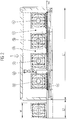
- FIG. 4 shows a schematic view of an embodiment of the unit 1 having an access space 70 suitable for the entrance of a person, wherein the access space 70 and the first fan 30 are located on opposite sides of the air heat exchanger 20.
- This access space 70 is preferably located on the air flap 90 side and provides a walk-in area for cleaning and inspection purposes.
- the inlet side of the coil of the air heat exchanger 20 is preferably accessible on its full length and can thus be easily cleaned.
- the air heat exchanger 20 may be accessed for inspection or cleaning purposes by means of a first closable opening 80 in the form of an inspection cover located above the air heat exchanger 20 and oriented horizontally in the drawing. Inspection covers on top of the coil can quickly be opened and allow one to wash down the coils from top to bottom if necessary. Therefore the coil may conveniently be cleaned while one is standing in an upright position.
- a further track member 46 is shown in the drawing.
- Another aspect of the invention is a process of using the unit 1 of the invention in providing cooled air to a refrigeration or freezer room or an air conditioning system in fluid communication with the unit 1.
- an inlet of the room or system is in fluid communication with the outlet 14 of the unit 1, and optionally an outlet of the room or system may be in fluid communication with the inlet 12 of the unit 1 in order to provide a recirculation.
- the flow of air through the unit is illustrated schematically by the use of arrows in FIG. 1 , and one skilled in the art will understand that other air flow paths and circulations may be obtained by making use of conventional air flow distributors, manifolds, baffles, deflectors, adjustable flaps, and other internals.
Landscapes
- Engineering & Computer Science (AREA)
- Chemical & Material Sciences (AREA)
- Combustion & Propulsion (AREA)
- Mechanical Engineering (AREA)
- General Engineering & Computer Science (AREA)
- Physics & Mathematics (AREA)
- Thermal Sciences (AREA)
- Cold Air Circulating Systems And Constructional Details In Refrigerators (AREA)
Claims (11)
- Une unité de refroidissement isolée (1) pour produire de l'air refroidi, comprenant à l'intérieur d'une chambre de boîtier thermiquement isolée (10) :- une entrée (12) pour introduire l'air à refroidir,- une sortie (14) pour la sortie de l'air refroidi,- un échangeur de chaleur à air (20) pour refroidir l'air,- un premier ventilateur (30),l'unité (1) comprend en outre- un premier élément de voie (40), ayant en option un premier élément de canal (42),- un ou plusieurs premier(s) élément(s) coulissant(s) (50) adapté(s) pour coulisser sur le premier élément de voie (40) ou dans le premier élément de canal optionnel (42),dans lequel le premier ventilateur (30) est connecté au premier élément coulissant (50), et
dans lequel le premier ventilateur (30) est monté de manière coulissante dans le premier élément de voie (40) au moyen du/des premier(s) élément(s) coulissant(s) (50), et dans lequel le premier ventilateur (30) peut être déplacé de manière coulissante sur une partie, de préférence entière, d'une première longueur (L1) du premier élément de voie (40), et caractérisé en ce que
l'unité (1) comprend en outre un à quatre, de préférence deux, ventilateur(s) supplémentaire(s) (32) relié(s) chacun à au moins un élément coulissant supplémentaire (52), et dans lequel chaque ventilateur supplémentaire (32) est monté de manière coulissante dans le premier élément de voie (40) au moyen du/des élément(s) coulissant(s) supplémentaire(s) (52), et dans lequel chaque ventilateur supplémentaire (32) peut être déplacé de manière coulissante sur une partie, de préférence entière, d'une première longueur (L1) du premier élément de voie (40). - L'unité (1) selon la revendication 1, dans lequel un espace de montage (60) est situé entre chacun du premier ventilateur (30) et un/les ventilateur(s) supplémentaire(s) (32).
- L'unité (1) selon l'une des revendications 1 à 2, dans lequel chacun du premier ventilateur (30) et un/les ventilateur(s) supplémentaire(s) (32) sont un ventilateur commuté électroniquement.
- L'unité (1) selon l'une des revendications 1 à 3, dans laquelle chacun du premier ventilateur (30) et un/les ventilateur(s) supplémentaire(s) (32) sont montés sur le premier élément de voie (40) via le premier élément coulissant (50) et un/les élément(s) coulissant(s) supplémentaire(s) (52) d'une manière telle qu'une direction (34) du flux d'air de chacun de premier ventilateur (30) et d'un/des ventilateur(s) supplémentaire(s) (32) est sensiblement perpendiculaire à un axe longitudinal (44) du premier élément de voie (40).
- L'unité (1) selon l'une des revendications 1 à 4, dans lequel le premier ventilateur (30) et un/les ventilateur(s) supplémentaire(s) (32) sont montés dans une orientation axiale horizontale.
- L'unité (1) selon la revendication 5, dans lequel la chambre (10) comprend un espace d'accès (70) approprié pour l'entrée d'une personne, l'espace d'accès (70) étant situé sur un côté de l'échangeur de chaleur à air (20), et le premier ventilateur (30) et un/les ventilateur(s) supplémentaire(s) (32) étant situé sur un côté opposé de l'échangeur de chaleur à air (20) à partir de l'espace d'accès (70).
- L'unité (1) selon la revendication 6, dans lequel l'échangeur de chaleur à air (20) est accessible à des fins d'inspection ou de nettoyage au moyen d'une première ouverture obturable (80), qui est située au-dessus de l'échangeur de chaleur à air (20) et dans lequel la première ouverture obturable (80) est de préférence orientée horizontalement.
- L'unité (1) selon la revendication 7, dans lequel la première ouverture obturable (80) comprend une porte.
- L'unité (1) selon l'une des revendications 1 à 8, dans lequel l'unité (1) comprend en outre :- un ou plusieurs élément(s) de voie supplémentaire(s) (46), chacun ayant en option un ou plusieurs élément(s) de canal supplémentaire(s) (48),- un ou plusieurs éléments coulissants supplémentaires (52) adaptés pour coulisser sur le/les élément(s) de voie supplémentaire(s) (46) ou à l'intérieur de/des élément(s) de canal supplémentaire(s) (48) optionnelsdans lequel le premier ventilateur (30) et un/les ventilateur(s) supplémentaire(s) (32) sont connectés aux éléments coulissants supplémentaires (52), et dans lequel le premier ventilateur (30) et un/les ventilateur(s) supplémentaire(s) (32) sont montés de manière coulissante dans les éléments de voie supplémentaires (46) au moyen du/des élément(s) coulissant(s) supplémentaire(s) (52), et dans lequel le premier ventilateur (30) et un/des ventilateur(s) supplémentaire(s) (32) peuvent être déplacés de manière coulissante sur une partie, de préférence entière, d'une première longueur (L1) du/les éléments de voie supplémentaire(s) (46).
- L'unité (1) selon l'une des revendications 1 à 9, dans lequel le premier élément de voie (40) et le premier élément de canal optionnel (42) et un/les élément(s) de voie supplémentaire(s) (46) et un/les élément(s) de canal supplémentaire(s) (48) s'étendent sur une seconde longueur (L2) à l'extérieur d'au moins une, de préférence deux parois (16) de la chambre (10), et dans lequel la deuxième longueur (L2) est de préférence plus longue qu'une largeur (W) du premier ventilateur (30), et dans lequel la chambre (10) présente au moins une, de préférence deux ouvertures obturables supplémentaires (82), dans lequel chaque ouverture obturable supplémentaire (82) peut être ouverte de telle sorte que le premier ventilateur (30) et un/les ventilateur(s) supplémentaire(s) peut/peuvent coulisser hors de la chambre (10) sur au moins une partie, de préférence entière, de la deuxième longueur (L2) du premier élément de voie (40) et un/les élément(s) de voie supplémentaire(s) (46), et dans lequel chaque ouverture obturable supplémentaire (82) peut être ouverte de telle sorte que la chambre (10) peut rester thermiquement isolée.
- L'unité (1) selon la revendication 10, dans lequel la/les ouverture(s) obturable(s) supplémentaire(s) (82) comprend/comprennent une porte.
Priority Applications (1)
| Application Number | Priority Date | Filing Date | Title |
|---|---|---|---|
| EP14710933.4A EP2984413B1 (fr) | 2013-04-09 | 2014-03-19 | Système d'accès pour faciliter l'entretien de l'unité de refroidisseur isolé |
Applications Claiming Priority (3)
| Application Number | Priority Date | Filing Date | Title |
|---|---|---|---|
| EP13162956 | 2013-04-09 | ||
| EP14710933.4A EP2984413B1 (fr) | 2013-04-09 | 2014-03-19 | Système d'accès pour faciliter l'entretien de l'unité de refroidisseur isolé |
| PCT/EP2014/055544 WO2014166715A1 (fr) | 2013-04-09 | 2014-03-19 | Système d'accès aisé pour maintenance, pour une unité de réfrigération isolée |
Publications (2)
| Publication Number | Publication Date |
|---|---|
| EP2984413A1 EP2984413A1 (fr) | 2016-02-17 |
| EP2984413B1 true EP2984413B1 (fr) | 2019-08-21 |
Family
ID=48050544
Family Applications (1)
| Application Number | Title | Priority Date | Filing Date |
|---|---|---|---|
| EP14710933.4A Active EP2984413B1 (fr) | 2013-04-09 | 2014-03-19 | Système d'accès pour faciliter l'entretien de l'unité de refroidisseur isolé |
Country Status (3)
| Country | Link |
|---|---|
| US (1) | US9739491B2 (fr) |
| EP (1) | EP2984413B1 (fr) |
| WO (1) | WO2014166715A1 (fr) |
Families Citing this family (4)
| Publication number | Priority date | Publication date | Assignee | Title |
|---|---|---|---|---|
| US10012399B2 (en) * | 2014-11-06 | 2018-07-03 | Lee Wa Wong | Window-type air conditioning system with water cooling unit |
| DE102016117913B4 (de) | 2016-09-22 | 2022-08-11 | Güntner Gmbh & Co. Kg | Kühleinrichtung zur Kühlung von begehbaren Kühlräumen und Wärmeübertrageranordnung zur Verwendung in einer solchen Kühleinrichtung |
| DE202016105281U1 (de) * | 2016-09-22 | 2018-01-09 | Güntner Gmbh & Co. Kg | Kühleinrichtung zur Kühlung von begehbaren Kühlräumen und Wärmeübertrageranordnung zur Verwendung in einer solchen Kühleinrichtung |
| US11906196B2 (en) | 2021-07-28 | 2024-02-20 | Johnson Controls Tyco IP Holdings LLP | Fan mounting assembly systems and methods |
Family Cites Families (8)
| Publication number | Priority date | Publication date | Assignee | Title |
|---|---|---|---|---|
| US4426120A (en) * | 1981-04-20 | 1984-01-17 | Mcquay Inc. | Sectioned cabinet for room air conditioning unit |
| US7108478B2 (en) | 2003-06-13 | 2006-09-19 | American Standard International Inc. | Blower housing and cabinet with improved blower inlet airflow distribution |
| KR100541472B1 (ko) * | 2003-08-18 | 2006-01-10 | 엘지전자 주식회사 | 일체형 공기조화기 |
| US20100041327A1 (en) * | 2006-12-29 | 2010-02-18 | Stulz Air Technology Systems, Inc. | Apparatus, system and method for air conditioning using fans located under flooring |
| FR2965735B1 (fr) * | 2010-10-08 | 2013-05-10 | Joodan Id | Procede et dispositif d'aspiration d'air modulaire |
| EP2503257B9 (fr) * | 2011-03-22 | 2014-06-04 | Erwin Gasser | Abri |
| US20120276836A1 (en) * | 2011-04-29 | 2012-11-01 | Trane International Inc. | Blower Assembly |
| DE202012001340U1 (de) | 2012-02-13 | 2012-03-27 | Thermofin Gmbh | Luftkühleranordnung |
-
2014
- 2014-03-19 EP EP14710933.4A patent/EP2984413B1/fr active Active
- 2014-03-19 WO PCT/EP2014/055544 patent/WO2014166715A1/fr active Application Filing
- 2014-03-19 US US14/780,042 patent/US9739491B2/en active Active
Non-Patent Citations (1)
| Title |
|---|
| None * |
Also Published As
| Publication number | Publication date |
|---|---|
| US20160047560A1 (en) | 2016-02-18 |
| WO2014166715A1 (fr) | 2014-10-16 |
| US9739491B2 (en) | 2017-08-22 |
| EP2984413A1 (fr) | 2016-02-17 |
Similar Documents
| Publication | Publication Date | Title |
|---|---|---|
| JP5310887B2 (ja) | 室外機及び冷凍装置 | |
| JP6293355B2 (ja) | 冷却液体を実装する適応可能コンテナ | |
| EP2984413B1 (fr) | Système d'accès pour faciliter l'entretien de l'unité de refroidisseur isolé | |
| EP2447636A1 (fr) | Module de réfrigération et système de réfrigération | |
| US20100307716A1 (en) | Hot aisle containment cooling unit and method for cooling | |
| JP2017183719A (ja) | ラックマウント冷却システム | |
| MX2015002198A (es) | Estante frigorifico. | |
| US10869411B2 (en) | Cooling system for rackmounted electronic equipment having independent evaporator and condenser airflows | |
| WO2008075050A2 (fr) | Système de refroidissement d'ordinateur | |
| WO2015186343A1 (fr) | Salle des accumulateurs | |
| WO2013046725A1 (fr) | Unité extérieure et dispositif de réfrigération | |
| CN106196334A (zh) | 空气调节器的室外机 | |
| CN105352040A (zh) | 空调柜机 | |
| RU158897U1 (ru) | Устройство системы охлаждения шкафа инвертора преобразователя частоты | |
| MX2015002200A (es) | Disposicion de estanteria frigorifica. | |
| KR101609051B1 (ko) | 열원장치 | |
| GB2519308A (en) | Evaporative Cooler Apparatus and Method | |
| WO2017141174A1 (fr) | Chambre d'essai | |
| GB2572563A (en) | Modular air conditioning unit | |
| US20140110088A1 (en) | Evaporator with Service Clip Configurations | |
| JP2012087954A (ja) | 熱源装置 | |
| US11231231B2 (en) | Cooler station for connection of a liquid cooler | |
| CN104110754A (zh) | 立式空调器室内机 | |
| KR101734640B1 (ko) | 공기 조화기의 실외기 | |
| CN109297092A (zh) | 空调室内机 |
Legal Events
| Date | Code | Title | Description |
|---|---|---|---|
| PUAI | Public reference made under article 153(3) epc to a published international application that has entered the european phase |
Free format text: ORIGINAL CODE: 0009012 |
|
| 17P | Request for examination filed |
Effective date: 20151109 |
|
| AK | Designated contracting states |
Kind code of ref document: A1 Designated state(s): AL AT BE BG CH CY CZ DE DK EE ES FI FR GB GR HR HU IE IS IT LI LT LU LV MC MK MT NL NO PL PT RO RS SE SI SK SM TR |
|
| AX | Request for extension of the european patent |
Extension state: BA ME |
|
| DAX | Request for extension of the european patent (deleted) | ||
| STAA | Information on the status of an ep patent application or granted ep patent |
Free format text: STATUS: EXAMINATION IS IN PROGRESS |
|
| 17Q | First examination report despatched |
Effective date: 20180209 |
|
| GRAP | Despatch of communication of intention to grant a patent |
Free format text: ORIGINAL CODE: EPIDOSNIGR1 |
|
| STAA | Information on the status of an ep patent application or granted ep patent |
Free format text: STATUS: GRANT OF PATENT IS INTENDED |
|
| RIC1 | Information provided on ipc code assigned before grant |
Ipc: F24F 1/04 20110101AFI20190321BHEP |
|
| INTG | Intention to grant announced |
Effective date: 20190417 |
|
| GRAS | Grant fee paid |
Free format text: ORIGINAL CODE: EPIDOSNIGR3 |
|
| GRAA | (expected) grant |
Free format text: ORIGINAL CODE: 0009210 |
|
| STAA | Information on the status of an ep patent application or granted ep patent |
Free format text: STATUS: THE PATENT HAS BEEN GRANTED |
|
| AK | Designated contracting states |
Kind code of ref document: B1 Designated state(s): AL AT BE BG CH CY CZ DE DK EE ES FI FR GB GR HR HU IE IS IT LI LT LU LV MC MK MT NL NO PL PT RO RS SE SI SK SM TR |
|
| REG | Reference to a national code |
Ref country code: GB Ref legal event code: FG4D |
|
| REG | Reference to a national code |
Ref country code: CH Ref legal event code: EP |
|
| REG | Reference to a national code |
Ref country code: DE Ref legal event code: R096 Ref document number: 602014052095 Country of ref document: DE |
|
| REG | Reference to a national code |
Ref country code: AT Ref legal event code: REF Ref document number: 1170201 Country of ref document: AT Kind code of ref document: T Effective date: 20190915 |
|
| REG | Reference to a national code |
Ref country code: IE Ref legal event code: FG4D |
|
| REG | Reference to a national code |
Ref country code: LT Ref legal event code: MG4D |
|
| REG | Reference to a national code |
Ref country code: NL Ref legal event code: MP Effective date: 20190821 |
|
| PG25 | Lapsed in a contracting state [announced via postgrant information from national office to epo] |
Ref country code: NO Free format text: LAPSE BECAUSE OF FAILURE TO SUBMIT A TRANSLATION OF THE DESCRIPTION OR TO PAY THE FEE WITHIN THE PRESCRIBED TIME-LIMIT Effective date: 20191121 Ref country code: NL Free format text: LAPSE BECAUSE OF FAILURE TO SUBMIT A TRANSLATION OF THE DESCRIPTION OR TO PAY THE FEE WITHIN THE PRESCRIBED TIME-LIMIT Effective date: 20190821 Ref country code: SE Free format text: LAPSE BECAUSE OF FAILURE TO SUBMIT A TRANSLATION OF THE DESCRIPTION OR TO PAY THE FEE WITHIN THE PRESCRIBED TIME-LIMIT Effective date: 20190821 Ref country code: BG Free format text: LAPSE BECAUSE OF FAILURE TO SUBMIT A TRANSLATION OF THE DESCRIPTION OR TO PAY THE FEE WITHIN THE PRESCRIBED TIME-LIMIT Effective date: 20191121 Ref country code: LT Free format text: LAPSE BECAUSE OF FAILURE TO SUBMIT A TRANSLATION OF THE DESCRIPTION OR TO PAY THE FEE WITHIN THE PRESCRIBED TIME-LIMIT Effective date: 20190821 Ref country code: PT Free format text: LAPSE BECAUSE OF FAILURE TO SUBMIT A TRANSLATION OF THE DESCRIPTION OR TO PAY THE FEE WITHIN THE PRESCRIBED TIME-LIMIT Effective date: 20191223 Ref country code: HR Free format text: LAPSE BECAUSE OF FAILURE TO SUBMIT A TRANSLATION OF THE DESCRIPTION OR TO PAY THE FEE WITHIN THE PRESCRIBED TIME-LIMIT Effective date: 20190821 |
|
| PG25 | Lapsed in a contracting state [announced via postgrant information from national office to epo] |
Ref country code: AL Free format text: LAPSE BECAUSE OF FAILURE TO SUBMIT A TRANSLATION OF THE DESCRIPTION OR TO PAY THE FEE WITHIN THE PRESCRIBED TIME-LIMIT Effective date: 20190821 Ref country code: GR Free format text: LAPSE BECAUSE OF FAILURE TO SUBMIT A TRANSLATION OF THE DESCRIPTION OR TO PAY THE FEE WITHIN THE PRESCRIBED TIME-LIMIT Effective date: 20191122 Ref country code: RS Free format text: LAPSE BECAUSE OF FAILURE TO SUBMIT A TRANSLATION OF THE DESCRIPTION OR TO PAY THE FEE WITHIN THE PRESCRIBED TIME-LIMIT Effective date: 20190821 Ref country code: LV Free format text: LAPSE BECAUSE OF FAILURE TO SUBMIT A TRANSLATION OF THE DESCRIPTION OR TO PAY THE FEE WITHIN THE PRESCRIBED TIME-LIMIT Effective date: 20190821 Ref country code: IS Free format text: LAPSE BECAUSE OF FAILURE TO SUBMIT A TRANSLATION OF THE DESCRIPTION OR TO PAY THE FEE WITHIN THE PRESCRIBED TIME-LIMIT Effective date: 20191221 Ref country code: ES Free format text: LAPSE BECAUSE OF FAILURE TO SUBMIT A TRANSLATION OF THE DESCRIPTION OR TO PAY THE FEE WITHIN THE PRESCRIBED TIME-LIMIT Effective date: 20190821 |
|
| REG | Reference to a national code |
Ref country code: AT Ref legal event code: MK05 Ref document number: 1170201 Country of ref document: AT Kind code of ref document: T Effective date: 20190821 |
|
| PG25 | Lapsed in a contracting state [announced via postgrant information from national office to epo] |
Ref country code: TR Free format text: LAPSE BECAUSE OF FAILURE TO SUBMIT A TRANSLATION OF THE DESCRIPTION OR TO PAY THE FEE WITHIN THE PRESCRIBED TIME-LIMIT Effective date: 20190821 |
|
| PG25 | Lapsed in a contracting state [announced via postgrant information from national office to epo] |
Ref country code: PL Free format text: LAPSE BECAUSE OF FAILURE TO SUBMIT A TRANSLATION OF THE DESCRIPTION OR TO PAY THE FEE WITHIN THE PRESCRIBED TIME-LIMIT Effective date: 20190821 Ref country code: AT Free format text: LAPSE BECAUSE OF FAILURE TO SUBMIT A TRANSLATION OF THE DESCRIPTION OR TO PAY THE FEE WITHIN THE PRESCRIBED TIME-LIMIT Effective date: 20190821 Ref country code: DK Free format text: LAPSE BECAUSE OF FAILURE TO SUBMIT A TRANSLATION OF THE DESCRIPTION OR TO PAY THE FEE WITHIN THE PRESCRIBED TIME-LIMIT Effective date: 20190821 Ref country code: EE Free format text: LAPSE BECAUSE OF FAILURE TO SUBMIT A TRANSLATION OF THE DESCRIPTION OR TO PAY THE FEE WITHIN THE PRESCRIBED TIME-LIMIT Effective date: 20190821 Ref country code: RO Free format text: LAPSE BECAUSE OF FAILURE TO SUBMIT A TRANSLATION OF THE DESCRIPTION OR TO PAY THE FEE WITHIN THE PRESCRIBED TIME-LIMIT Effective date: 20190821 |
|
| PG25 | Lapsed in a contracting state [announced via postgrant information from national office to epo] |
Ref country code: CZ Free format text: LAPSE BECAUSE OF FAILURE TO SUBMIT A TRANSLATION OF THE DESCRIPTION OR TO PAY THE FEE WITHIN THE PRESCRIBED TIME-LIMIT Effective date: 20190821 Ref country code: SK Free format text: LAPSE BECAUSE OF FAILURE TO SUBMIT A TRANSLATION OF THE DESCRIPTION OR TO PAY THE FEE WITHIN THE PRESCRIBED TIME-LIMIT Effective date: 20190821 Ref country code: IS Free format text: LAPSE BECAUSE OF FAILURE TO SUBMIT A TRANSLATION OF THE DESCRIPTION OR TO PAY THE FEE WITHIN THE PRESCRIBED TIME-LIMIT Effective date: 20200224 Ref country code: SM Free format text: LAPSE BECAUSE OF FAILURE TO SUBMIT A TRANSLATION OF THE DESCRIPTION OR TO PAY THE FEE WITHIN THE PRESCRIBED TIME-LIMIT Effective date: 20190821 |
|
| REG | Reference to a national code |
Ref country code: DE Ref legal event code: R097 Ref document number: 602014052095 Country of ref document: DE |
|
| PLBE | No opposition filed within time limit |
Free format text: ORIGINAL CODE: 0009261 |
|
| STAA | Information on the status of an ep patent application or granted ep patent |
Free format text: STATUS: NO OPPOSITION FILED WITHIN TIME LIMIT |
|
| PG2D | Information on lapse in contracting state deleted |
Ref country code: IS |
|
| 26N | No opposition filed |
Effective date: 20200603 |
|
| PG25 | Lapsed in a contracting state [announced via postgrant information from national office to epo] |
Ref country code: SI Free format text: LAPSE BECAUSE OF FAILURE TO SUBMIT A TRANSLATION OF THE DESCRIPTION OR TO PAY THE FEE WITHIN THE PRESCRIBED TIME-LIMIT Effective date: 20190821 |
|
| PG25 | Lapsed in a contracting state [announced via postgrant information from national office to epo] |
Ref country code: MC Free format text: LAPSE BECAUSE OF FAILURE TO SUBMIT A TRANSLATION OF THE DESCRIPTION OR TO PAY THE FEE WITHIN THE PRESCRIBED TIME-LIMIT Effective date: 20190821 |
|
| REG | Reference to a national code |
Ref country code: CH Ref legal event code: PL |
|
| REG | Reference to a national code |
Ref country code: BE Ref legal event code: MM Effective date: 20200331 |
|
| PG25 | Lapsed in a contracting state [announced via postgrant information from national office to epo] |
Ref country code: LU Free format text: LAPSE BECAUSE OF NON-PAYMENT OF DUE FEES Effective date: 20200319 |
|
| PG25 | Lapsed in a contracting state [announced via postgrant information from national office to epo] |
Ref country code: LI Free format text: LAPSE BECAUSE OF NON-PAYMENT OF DUE FEES Effective date: 20200331 Ref country code: CH Free format text: LAPSE BECAUSE OF NON-PAYMENT OF DUE FEES Effective date: 20200331 Ref country code: IE Free format text: LAPSE BECAUSE OF NON-PAYMENT OF DUE FEES Effective date: 20200319 Ref country code: FR Free format text: LAPSE BECAUSE OF NON-PAYMENT OF DUE FEES Effective date: 20200331 |
|
| PG25 | Lapsed in a contracting state [announced via postgrant information from national office to epo] |
Ref country code: BE Free format text: LAPSE BECAUSE OF NON-PAYMENT OF DUE FEES Effective date: 20200331 |
|
| GBPC | Gb: european patent ceased through non-payment of renewal fee |
Effective date: 20200319 |
|
| PG25 | Lapsed in a contracting state [announced via postgrant information from national office to epo] |
Ref country code: GB Free format text: LAPSE BECAUSE OF NON-PAYMENT OF DUE FEES Effective date: 20200319 |
|
| PG25 | Lapsed in a contracting state [announced via postgrant information from national office to epo] |
Ref country code: MT Free format text: LAPSE BECAUSE OF FAILURE TO SUBMIT A TRANSLATION OF THE DESCRIPTION OR TO PAY THE FEE WITHIN THE PRESCRIBED TIME-LIMIT Effective date: 20190821 Ref country code: CY Free format text: LAPSE BECAUSE OF FAILURE TO SUBMIT A TRANSLATION OF THE DESCRIPTION OR TO PAY THE FEE WITHIN THE PRESCRIBED TIME-LIMIT Effective date: 20190821 |
|
| PG25 | Lapsed in a contracting state [announced via postgrant information from national office to epo] |
Ref country code: MK Free format text: LAPSE BECAUSE OF FAILURE TO SUBMIT A TRANSLATION OF THE DESCRIPTION OR TO PAY THE FEE WITHIN THE PRESCRIBED TIME-LIMIT Effective date: 20190821 |
|
| PGFP | Annual fee paid to national office [announced via postgrant information from national office to epo] |
Ref country code: FI Payment date: 20240320 Year of fee payment: 11 Ref country code: DE Payment date: 20240320 Year of fee payment: 11 |
|
| PGFP | Annual fee paid to national office [announced via postgrant information from national office to epo] |
Ref country code: IT Payment date: 20240329 Year of fee payment: 11 |