EP2953120B1 - Signal conversion device and method, and display device - Google Patents
Signal conversion device and method, and display device Download PDFInfo
- Publication number
- EP2953120B1 EP2953120B1 EP14861139.5A EP14861139A EP2953120B1 EP 2953120 B1 EP2953120 B1 EP 2953120B1 EP 14861139 A EP14861139 A EP 14861139A EP 2953120 B1 EP2953120 B1 EP 2953120B1
- Authority
- EP
- European Patent Office
- Prior art keywords
- brightness
- rgb
- values
- rgbw
- value
- Prior art date
- Legal status (The legal status is an assumption and is not a legal conclusion. Google has not performed a legal analysis and makes no representation as to the accuracy of the status listed.)
- Active
Links
Images


Classifications
-
- G—PHYSICS
- G09—EDUCATION; CRYPTOGRAPHY; DISPLAY; ADVERTISING; SEALS
- G09G—ARRANGEMENTS OR CIRCUITS FOR CONTROL OF INDICATING DEVICES USING STATIC MEANS TO PRESENT VARIABLE INFORMATION
- G09G3/00—Control arrangements or circuits, of interest only in connection with visual indicators other than cathode-ray tubes
- G09G3/20—Control arrangements or circuits, of interest only in connection with visual indicators other than cathode-ray tubes for presentation of an assembly of a number of characters, e.g. a page, by composing the assembly by combination of individual elements arranged in a matrix no fixed position being assigned to or needed to be assigned to the individual characters or partial characters
- G09G3/34—Control arrangements or circuits, of interest only in connection with visual indicators other than cathode-ray tubes for presentation of an assembly of a number of characters, e.g. a page, by composing the assembly by combination of individual elements arranged in a matrix no fixed position being assigned to or needed to be assigned to the individual characters or partial characters by control of light from an independent source
- G09G3/3406—Control of illumination source
- G09G3/3413—Details of control of colour illumination sources
-
- G—PHYSICS
- G09—EDUCATION; CRYPTOGRAPHY; DISPLAY; ADVERTISING; SEALS
- G09G—ARRANGEMENTS OR CIRCUITS FOR CONTROL OF INDICATING DEVICES USING STATIC MEANS TO PRESENT VARIABLE INFORMATION
- G09G3/00—Control arrangements or circuits, of interest only in connection with visual indicators other than cathode-ray tubes
- G09G3/20—Control arrangements or circuits, of interest only in connection with visual indicators other than cathode-ray tubes for presentation of an assembly of a number of characters, e.g. a page, by composing the assembly by combination of individual elements arranged in a matrix no fixed position being assigned to or needed to be assigned to the individual characters or partial characters
- G09G3/2003—Display of colours
-
- G—PHYSICS
- G09—EDUCATION; CRYPTOGRAPHY; DISPLAY; ADVERTISING; SEALS
- G09G—ARRANGEMENTS OR CIRCUITS FOR CONTROL OF INDICATING DEVICES USING STATIC MEANS TO PRESENT VARIABLE INFORMATION
- G09G3/00—Control arrangements or circuits, of interest only in connection with visual indicators other than cathode-ray tubes
- G09G3/20—Control arrangements or circuits, of interest only in connection with visual indicators other than cathode-ray tubes for presentation of an assembly of a number of characters, e.g. a page, by composing the assembly by combination of individual elements arranged in a matrix no fixed position being assigned to or needed to be assigned to the individual characters or partial characters
- G09G3/2092—Details of a display terminals using a flat panel, the details relating to the control arrangement of the display terminal and to the interfaces thereto
- G09G3/2096—Details of the interface to the display terminal specific for a flat panel
-
- G—PHYSICS
- G09—EDUCATION; CRYPTOGRAPHY; DISPLAY; ADVERTISING; SEALS
- G09G—ARRANGEMENTS OR CIRCUITS FOR CONTROL OF INDICATING DEVICES USING STATIC MEANS TO PRESENT VARIABLE INFORMATION
- G09G3/00—Control arrangements or circuits, of interest only in connection with visual indicators other than cathode-ray tubes
- G09G3/20—Control arrangements or circuits, of interest only in connection with visual indicators other than cathode-ray tubes for presentation of an assembly of a number of characters, e.g. a page, by composing the assembly by combination of individual elements arranged in a matrix no fixed position being assigned to or needed to be assigned to the individual characters or partial characters
- G09G3/22—Control arrangements or circuits, of interest only in connection with visual indicators other than cathode-ray tubes for presentation of an assembly of a number of characters, e.g. a page, by composing the assembly by combination of individual elements arranged in a matrix no fixed position being assigned to or needed to be assigned to the individual characters or partial characters using controlled light sources
- G09G3/30—Control arrangements or circuits, of interest only in connection with visual indicators other than cathode-ray tubes for presentation of an assembly of a number of characters, e.g. a page, by composing the assembly by combination of individual elements arranged in a matrix no fixed position being assigned to or needed to be assigned to the individual characters or partial characters using controlled light sources using electroluminescent panels
- G09G3/32—Control arrangements or circuits, of interest only in connection with visual indicators other than cathode-ray tubes for presentation of an assembly of a number of characters, e.g. a page, by composing the assembly by combination of individual elements arranged in a matrix no fixed position being assigned to or needed to be assigned to the individual characters or partial characters using controlled light sources using electroluminescent panels semiconductive, e.g. using light-emitting diodes [LED]
- G09G3/3208—Control arrangements or circuits, of interest only in connection with visual indicators other than cathode-ray tubes for presentation of an assembly of a number of characters, e.g. a page, by composing the assembly by combination of individual elements arranged in a matrix no fixed position being assigned to or needed to be assigned to the individual characters or partial characters using controlled light sources using electroluminescent panels semiconductive, e.g. using light-emitting diodes [LED] organic, e.g. using organic light-emitting diodes [OLED]
-
- G—PHYSICS
- G09—EDUCATION; CRYPTOGRAPHY; DISPLAY; ADVERTISING; SEALS
- G09G—ARRANGEMENTS OR CIRCUITS FOR CONTROL OF INDICATING DEVICES USING STATIC MEANS TO PRESENT VARIABLE INFORMATION
- G09G5/00—Control arrangements or circuits for visual indicators common to cathode-ray tube indicators and other visual indicators
- G09G5/02—Control arrangements or circuits for visual indicators common to cathode-ray tube indicators and other visual indicators characterised by the way in which colour is displayed
- G09G5/04—Control arrangements or circuits for visual indicators common to cathode-ray tube indicators and other visual indicators characterised by the way in which colour is displayed using circuits for interfacing with colour displays
-
- G—PHYSICS
- G09—EDUCATION; CRYPTOGRAPHY; DISPLAY; ADVERTISING; SEALS
- G09G—ARRANGEMENTS OR CIRCUITS FOR CONTROL OF INDICATING DEVICES USING STATIC MEANS TO PRESENT VARIABLE INFORMATION
- G09G2300/00—Aspects of the constitution of display devices
- G09G2300/04—Structural and physical details of display devices
- G09G2300/0439—Pixel structures
- G09G2300/0452—Details of colour pixel setup, e.g. pixel composed of a red, a blue and two green components
-
- G—PHYSICS
- G09—EDUCATION; CRYPTOGRAPHY; DISPLAY; ADVERTISING; SEALS
- G09G—ARRANGEMENTS OR CIRCUITS FOR CONTROL OF INDICATING DEVICES USING STATIC MEANS TO PRESENT VARIABLE INFORMATION
- G09G2320/00—Control of display operating conditions
- G09G2320/02—Improving the quality of display appearance
- G09G2320/0238—Improving the black level
-
- G—PHYSICS
- G09—EDUCATION; CRYPTOGRAPHY; DISPLAY; ADVERTISING; SEALS
- G09G—ARRANGEMENTS OR CIRCUITS FOR CONTROL OF INDICATING DEVICES USING STATIC MEANS TO PRESENT VARIABLE INFORMATION
- G09G2320/00—Control of display operating conditions
- G09G2320/06—Adjustment of display parameters
- G09G2320/0626—Adjustment of display parameters for control of overall brightness
-
- G—PHYSICS
- G09—EDUCATION; CRYPTOGRAPHY; DISPLAY; ADVERTISING; SEALS
- G09G—ARRANGEMENTS OR CIRCUITS FOR CONTROL OF INDICATING DEVICES USING STATIC MEANS TO PRESENT VARIABLE INFORMATION
- G09G2320/00—Control of display operating conditions
- G09G2320/06—Adjustment of display parameters
- G09G2320/0673—Adjustment of display parameters for control of gamma adjustment, e.g. selecting another gamma curve
-
- G—PHYSICS
- G09—EDUCATION; CRYPTOGRAPHY; DISPLAY; ADVERTISING; SEALS
- G09G—ARRANGEMENTS OR CIRCUITS FOR CONTROL OF INDICATING DEVICES USING STATIC MEANS TO PRESENT VARIABLE INFORMATION
- G09G2330/00—Aspects of power supply; Aspects of display protection and defect management
- G09G2330/02—Details of power systems and of start or stop of display operation
- G09G2330/021—Power management, e.g. power saving
- G09G2330/023—Power management, e.g. power saving using energy recovery or conservation
-
- G—PHYSICS
- G09—EDUCATION; CRYPTOGRAPHY; DISPLAY; ADVERTISING; SEALS
- G09G—ARRANGEMENTS OR CIRCUITS FOR CONTROL OF INDICATING DEVICES USING STATIC MEANS TO PRESENT VARIABLE INFORMATION
- G09G2340/00—Aspects of display data processing
- G09G2340/06—Colour space transformation
-
- G—PHYSICS
- G09—EDUCATION; CRYPTOGRAPHY; DISPLAY; ADVERTISING; SEALS
- G09G—ARRANGEMENTS OR CIRCUITS FOR CONTROL OF INDICATING DEVICES USING STATIC MEANS TO PRESENT VARIABLE INFORMATION
- G09G5/00—Control arrangements or circuits for visual indicators common to cathode-ray tube indicators and other visual indicators
- G09G5/02—Control arrangements or circuits for visual indicators common to cathode-ray tube indicators and other visual indicators characterised by the way in which colour is displayed
- G09G5/06—Control arrangements or circuits for visual indicators common to cathode-ray tube indicators and other visual indicators characterised by the way in which colour is displayed using colour palettes, e.g. look-up tables
Definitions
- the present invention relates to the field of display technology, and particularly relates to a signal conversion device, a signal conversion method and a display device.
- US patent application US 2009/262148 A1 discloses a hold-type display device having a fine luminance efficiency while suppressing generation of motion blur, wherein a controller adjusts a signal outputted to a hold-type image display panel, which includes: a double-speed drive converting part which divides one frame of an inputted video signal to a plurality of sub-frames; a color converting part which converts a video signal of three primary colors including the plurality of sub-frames to a video signal of four or more colors including the three primary colors and a compound color; and a sub-frame converting part which converts, the video signal converted by the color converting part, to a signal having a plurality of different gradations whose average luminance value becomes equivalent to luminance of the video signal converted by the color converting part, and takes each of the plurality of gradations as each of gradations of the plurality of sub-frames.
- US patent application US 2013/257924 A1 discloses a display device which includes a display portion having red, green, blue and white sub pixels, a converter generating red, green and blue conversion signals using a brightness ratio from a ratio storage, an upper limit value calculator calculating an upper limit value of a display brightness of the white sub pixel using the red, green and blue conversion signals and the brightness ratio, a lower limit value calculator calculating a lower limit value of the display brightness of the white sub pixel using the red, green and blue conversion signals and the brightness ratio, and a white control signal generator generating a white output control signal for controlling the display brightness of the white sub pixel such that the display brightness is not more than the upper limit value and not less than the lower limit value, and outputting the generated white output control signal to the display portion.
- the present invention provides a signal conversion device, a signal conversion method and a display device for increasing the brightness of a displayed image without changing power consumption and for decreasing power consumption of light emitting devices without changing display brightness of the displayed image.
- the present invention provides a signal conversion device including a gamma conversion unit, a brightness detection unit and a brightness processing unit, wherein the gamma conversion unit is used for performing a gamma conversion process on RGB input signals and generating RGB brightness input values; the brightness detection unit is used for generating a W brightness input value based on RGB proportional coefficients and the RGB brightness input values; and the brightness processing unit is used for generating RGBW output signals based on the RGB proportional coefficients, the RGB brightness input values and the W brightness input value.
- the brightness processing unit includes a brightness calculation unit and a reverse gamma conversion unit, wherein the brightness calculation unit generates RGBW brightness output values based on the RGB proportional coefficients, the RGB brightness input values and the W brightness input value, and outputs the RGBW brightness output values to the reverse gamma conversion unit; and the reverse gamma conversion unit generates the RGBW output signals based on the RGBW brightness output values, and the brightness processing unit further includes a brightness scaling unit for performing a scaling process on maximum RGBW brightness values based on brightness scaling coefficients, generating the scaled maximum RGBW brightness values, and outputting the scaled maximum RGBW brightness values to the gamma conversion unit and the reverse gamma conversion unit, wherein the gamma conversion unit performs the gamma conversion process on the RGB input signals based on the scaled maximum RGBW brightness values, generates the RGB brightness input values, and outputs the RGB brightness input values to the brightness detection unit and the brightness calculation unit; and the reverse gamma conversion unit generate
- the gamma conversion unit performs the gamma conversion process on the RGB input signals based on the maximum RGBW brightness values, generates RGB brightness input values, and outputs the RGB brightness input values to the brightness detection unit and the brightness calculation unit;
- the brightness calculation unit generates the RGBW brightness output values based on the RGB proportional coefficients, the RGB brightness input values and the W brightness input value, and outputs the RGBW brightness output values to the brightness scaling unit;
- the brightness scaling unit performs a scaling process on the RGBW brightness output values based on brightness scaling coefficients, generates scaled RGBW brightness output values, and outputs the scaled RGBW brightness output values to the reverse gamma conversion unit, and the reverse gamma conversion unit generates the RGBW output signals based on the maximum RGBW brightness values and the scaled RGBW brightness output values.
- the scaled maximum RGBW brightness values include a scaled maximum R brightness value L R max , a scaled maximum G brightness value L G max , a scaled maximum B brightness value L B max , and a scaled maximum W brightness value L W max ;
- the RGB input signals include a R input signal Ri , a G input signal Gi and a B input signal Bi ;
- the RGB brightness input values include a R brightness input value L R , a G brightness input value L G and a B brightness input value L B ; and equations for the RGBW brightness input values are:
- L R L R ⁇ max ⁇ Ri 2 n ⁇
- L G L G ⁇ max ⁇ Gi 2 n ⁇
- L B L B ⁇ max ⁇ Bi 2 n ⁇
- n is the number of bits of the RGB input signals and ⁇ is a gamma value.
- the RGBW brightness output values include a R brightness output value L R' , a G brightness output value L G' , a B brightness output value L B' , and a W brightness output value L W'
- the RGB proportional coefficients include a R proportional coefficient R R , a G proportional coefficient R G and a B proportional coefficient R B
- L G' L G - L W ⁇ R G
- L B' L B - L W ⁇ R B
- L W ' L W , respectively, where L W is the W brightness input value.
- the RGBW output signals include a R output signal Ro, a G output signal Go, a B output signal Bo and a W output signal Wo ;
- Bo L B ′ L B ⁇ max 1 ⁇ ⁇ 2 n
- Wo L W ′ L W ⁇ max 1 ⁇ ⁇ 2 n , respectively.
- the brightness scaling coefficient of the brightness scaling unit is K
- the maximum R brightness value is L R' max
- the maximum G brightness value is L G' max
- the maximum B brightness value is L B' max
- the maximum W brightness value is L W' max
- L R max K ⁇ L R' max
- L G max K ⁇ L G 'max
- L B max K ⁇ L B 'max
- L W max K ⁇ L W' max
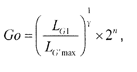
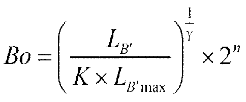
- Ro L R ′ K ⁇ L R ′ max 1 ⁇ ⁇ 2 n
- Go L G ′ K ⁇ L G ′ max 1 ⁇ ⁇ 2 n
- Wo L W ′ K ⁇ L W ′ max 1 ⁇ ⁇ 2 n .
- the RGB input signals include a R input signal Ri , a G input signal Gi and a B input signal Bi
- the RGB brightness input values include a R brightness input value L R , a G brightness input value L G and a B brightness input value L B
- L G L G ′ max ⁇ Gi 2 n ⁇
- L B L B ′ max ⁇ Bi 2 n ⁇
- n is the number of bits of the RGB input signals
- ⁇ is a gamma value
- L R' max is the maximum R brightness value
- L G 'max is the maximum G brightness value
- L B' max is the maximum B brightness value.
- the RGBW brightness output values include a R brightness output value L R' , a G brightness output value L G' , a B brightness output value L B' , and a W brightness output value L W'
- the RGB proportional coefficients include a R proportional coefficient R R , a G proportional coefficient R G and a B proportional coefficient R B
- L G' L G - L W ⁇ R G
- L B' L B - L W ⁇ R B
- L W' L W , respectively, wherein L W is the W brightness input value.
- the RGBW output signals include a R output signal Ro, a G output signal Go, a B output signal Bo and a W output signal Wo ;
- the brightness scaling coefficient of the brightness scaling unit is 1/K
- L R 1 L R ′ K
- L G 1 L G ′ K
- L B 1 L B ′ K
- L W 1 L W ′ K
- Bo L B ′ K ⁇ L B ′ max 1 ⁇ ⁇ 2 n
- Wo L W ′ K ⁇ L W ′ max 1 ⁇ ⁇ 2 n , respectively.
- the signal conversion device further includes a RGB proportion calculation unit, wherein the RGB proportion calculation unit is used for calculating the RGB proportional coefficients based on color coordinates for RGBW.
- the color coordinates for RGBW include a R color coordinate R ( x R ,y R ), a G color coordinate G ( x G , y G ), a B color coordinate B ( x B ,y B ) and a W color coordinate W ( x W ,y W ).
- the brightness detection unit generates RGB brightness substitute values based on the RGB proportional coefficients and the RGB brightness input values, and selects a minimum value from the RGB brightness substitute values as the W brightness input value.
- the present invention provides a display device, including the above-described signal conversion device.
- the present invention provides a signal conversion method, including the following steps of S1 to S3.
- the step S3 includes a step of generating RGBW brightness output values based on the RGB proportional coefficients, the RGB brightness input values and the W brightness input value, and a step of generating the RGBW output signals based on the RGBW brightness output values
- the step S1 further includes a step of generating scaled maximum RGBW brightness values by performing a scaling process on maximum RGBW brightness values based on brightness scaling coefficients and a step of generating RGB brightness input values by performing a gamma conversion process on the RGB input signals based the scaled maximum RGBW brightness values
- the step S3 further includes a step of generating the RGBW output signals based on the scaled maximum RGBW brightness values and the RGBW brightness output values.
- the step S1 further includes a step of generating the RGB brightness input values by performing a gamma conversion process on the RGB input signals based on the maximum RGBW brightness values
- the step S3 further includes a step of generating scaled RGBW brightness output values by performing a scaling process on the RGBW brightness output values based on the brightness scaling coefficients and a step of generating the RGBW output signals based on the maximum RGBW brightness values and the scaled RGBW brightness output values.
- the signal conversion method according to both aspects of the invention further includes a step of calculating the RGB proportional coefficients based on color coordinates for RGBW.
- the step S2 further includes a step of generating RGB brightness substitute values based on the RGB proportional coefficients and the RGB brightness input values and obtaining the W brightness input value by selecting a minimum value from the RGB brightness substitute values.
- the gamma conversion unit is used for performing a gamma conversion process on RGB input signals and generating RGB brightness input values
- the brightness detection unit is used for generating a W brightness input value based on RGB proportional coefficients and the RGB brightness input values
- the brightness processing unit is used for generating RGBW output signals based on the RGB proportional coefficients, the RGB brightness input values and the W brightness input value.
- the brightness of a displayed image can be increased with a premise that the power consumption is not changed, so that the contrast of the displayed image is increased, and the display quality of the image is also improved.
- the power consumption of light emitting devices is reduced with a premise that the display brightness of a displayed image is not changed, so that the lifetime of the light emitting devices is increased, the cost of driving chips is reduced and thus the manufacturing cost of products is reduced.
- Fig. 1 is a schematic diagram of a structure of a signal conversion device provided by Embodiment 1 of the present invention.
- the device includes a gamma conversion unit 11, a brightness detection unit 12 and a brightness processing unit 13.
- the gamma conversion unit 11 is used for generating RGB brightness input values by performing a gamma conversion process on RGB input signals.
- the brightness detection unit 12 is used for generating a W brightness input value based on RGB proportional coefficients and the RGB brightness input values.
- the brightness processing unit 13 is used for generating RGBW output signals based on the RGB proportional coefficients, the RGB brightness input values and the W brightness input value.
- R represents red
- G represents green
- B represents blue and W represents white.
- the brightness processing unit 13 includes a brightness calculation unit 14 and a reverse gamma conversion unit 15.
- the brightness calculation unit 14 is used for generating RGBW brightness output values based on the RGB proportional coefficients, the RGB brightness input values and the W brightness input value, and outputs the RGBW brightness output values to the reverse gamma conversion unit 15.
- the reverse gamma conversion unit 15 is used for generating RGBW output signals based on the RGBW brightness output values.
- the brightness processing unit 13 also includes a brightness scaling unit 16.
- the brightness scaling unit 16 is used for performing a scaling process on maximum RGBW brightness values based on brightness scaling coefficients, generating scaled maximum RGBW brightness values, and outputting the scaled maximum RGBW brightness values to the gamma conversion unit 11 and the reverse gamma conversion unit 15.
- the maximum RGBW brightness values include a maximum R brightness value L R' max , a maximum G brightness value L G' max , a maximum B brightness value L B 'max and a maximum W brightness value L W' max
- the scaled maximum RGBW brightness values include a scaled maximum R brightness value L R max , a scaled maximum G brightness value L G max , a scaled maximum B brightness value L B max , and a scaled maximum W brightness value L W max .
- the gamma conversion unit 11 is specifically used for performing a gamma conversion process on the RGB input signals based on the scaled maximum RGBW brightness values, generating the RGB brightness input values, and outputting the RGB brightness input values to the brightness detection unit 12 and the brightness calculation unit 14.
- the RGB input signals include a R input signal Ri , a G input signal Gi and a B input signal Bi
- the RGB brightness input values include a R brightness input value L R , a G brightness input value L G and a B brightness input value L B
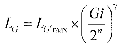
- L G L G ⁇ max ⁇ Gi 2 n ⁇
- L B L B ⁇ max ⁇ Bi 2 n ⁇
- n is the number of bits of RGB input signals and ⁇ is a gamma value and may be ranged from 2.0 to 2.4.
- the brightness detection unit 12 is specifically used for generating RGB brightness substitute values based on the RGB proportional coefficients and the RGB brightness input values, obtaining the W brightness input value by selecting a minimum value from the RGB brightness substitute values, and outputting the W brightness input value to the brightness calculation unit 14.
- the RGB proportional coefficients include a R proportional coefficient R R , a G proportional coefficient R G and a B proportional coefficient R B
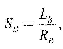
- the RGB brightness substitute values include a R brightness substitute value S R , a G brightness substitute value S G and a B brightness substitute value S B
- the W brightness input value is L W .
- the signal conversion device further includes a RGB proportion calculation unit 17, wherein the RGB proportion calculation unit 17 is used for calculating the RGB proportional coefficients based on color coordinates for RGBW, and outputting the RGB proportional coefficients to the brightness detection unit 12 and the brightness calculation unit 14.
- the color coordinates for RGBW include a R color coordinate R ( x R , y R ), a G color coordinate G ( x G ,y G ), a B color coordinate B ( x B , y B ) and a W color coordinate W ( x W , y W ).
- Equation (1) for the RGB proportional coefficients may be:
- equation (2) for the RGB proportional coefficients may be:
- the RGBW brightness output values include a R brightness output value L R' , a G brightness output value L G' , a B brightness output value L B' , and a W brightness output value L W '
- the reverse gamma conversion unit 15 is specifically used for generating the RGBW output signals based on the scaled maximum RGBW brightness values and the RGBW brightness output values.
- Go L G ′ L G ⁇ max 1 2.2 ⁇ 255
- Bo L B ′ L B ⁇ max 1 2.2 ⁇ 255
- Wo L W ′ L W max 1 2.2 ⁇ 255
- Go L G ′ K ⁇ L G ′ max 1 ⁇ ⁇ 2 n
- Bo L B ′ K ⁇ L B ′ max 1 ⁇ ⁇ 2 n
- Wo L W ′ K ⁇ L W ′ max 1 ⁇ ⁇ 2 n .
- the gamma conversion unit is used for performing a gamma conversion process on RGB input signals and generating RGB brightness input values
- the brightness detection unit is used for generating a W brightness input value based on RGB proportional coefficients and the RGB brightness input values
- the brightness processing unit is used for generating RGBW output signals based on the RGB proportional coefficients, the RGB brightness input values and the W brightness input value.
- the power consumption of light emitting devices is reduced with a premise that the display brightness of a displayed image is not changed, so that the lifetime of the light emitting devices is increased, the cost of driving chips is reduced and thus the manufacturing cost of products is reduced. Furthermore, with the present embodiment, the manufacturing cost of power supply can be reduced since the power consumption of light emitting devices is reduced, and thus the manufacturing cost of products is reduced.
- the brightness scaling unit can generate scaled maximum RGBW brightness values by performing the scaling process on the maximum RGBW brightness values based on the brightness scaling coefficients, so that the brightness of the displayed image can be further improved.
- Fig. 2 is a schematic diagram of a structure of a signal conversion device provided by Embodiment 2 of the present invention. As shown in Fig. 2 , the difference between the signal conversion device provided by this embodiment and that provided by Embodiment 1 is a brightness processing unit 21 including a brightness calculation unit 14, a brightness scaling unit 22 and a reverse gamma conversion unit 23.
- the brightness calculation unit 14 outputs RGBW brightness output values to the brightness scaling unit 22.
- the brightness scaling unit 22 is used for performing a scaling process on the RGBW brightness output values based on brightness scaling coefficients, generating scaled RGBW brightness output values, and outputting the scaled RGBW brightness output values to the reverse gamma conversion unit 23.
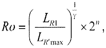
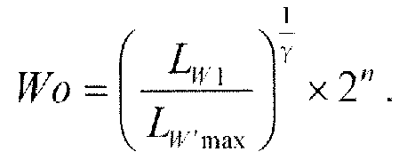
- the scaled RGBW brightness output values include a scaled R brightness output value L R 1 , a scaled G brightness output value L G 1 , a scaled B brightness output value L B 1 and a scaled W brightness output value L W 1 .
- the reverse gamma conversion unit 23 is used for generating RGBW output signals based on the maximum RGBW brightness values L R' max , L G' max , L B' max , L W' max and the scaled RGBW brightness output values.
- the calculation results from the equations for the RGBW output signals in this embodiment are the same as the calculation results from the equations for the RGBW output signals in Embodiment 1 described above.
- the gamma conversion unit is used for performing a gamma conversion process on RGB input signals and generating RGB brightness input values
- the brightness detection unit is used for generating a W brightness input value based on RGB proportional coefficients and the RGB brightness input values
- the brightness processing unit is used for generating RGBW output signals based on the RGB proportional coefficients, the RGB brightness input values and the W brightness input value.
- the power consumption of light emitting devices is reduced with a premise that the display brightness of a displayed image is not changed, so that the lifetime of the light emitting devices is increased, the cost of driving chips is reduced and thus the manufacturing cost of products is reduced. Furthermore, with the present embodiment, the manufacturing cost of power supply can be reduced since the power consumption of light emitting devices is reduced, and thus the manufacturing cost of products is reduced.
- the brightness scaling unit can generate scaled RGBW brightness output values by performing the scaling process on the RGBW brightness output values based on the brightness scaling coefficients, so that the brightness of the displayed image can be further improved.
- Embodiment 3 of the present invention provides a display device including a signal conversion device.
- the signal conversion device may adopt the signal conversion device provided by Embodiment 1 or Embodiment 2, and will not be redundantly described here.
- the display device may include an OLED display device or a liquid crystal display device.
- the gamma conversion unit is used for performing a gamma conversion process on RGB input signals and generating RGB brightness input values
- the brightness detection unit is used for generating a W brightness input value based on RGB proportional coefficients and the RGB brightness input values
- the brightness processing unit is used for generating RGBW output signals based on the RGB proportional coefficients, the RGB brightness input values and the W brightness input value.
- the power consumption of light emitting devices is reduced with a premise that the display brightness of a displayed image is not changed, so that the lifetime of the light emitting devices is increased, the cost of driving chips is reduced and thus the manufacturing cost of products is reduced. Furthermore, with the present embodiment, the manufacturing cost of power supply can be reduced since the power consumption of light emitting devices is reduced, and thus the manufacturing cost of products is reduced. Specially, in a case where the display device is an OLED display device, with the present embodiment, the current flowing through light emitting devices can be effectively reduced, so that the power consumption of light emitting devices can be greatly reduced.
- Fig. 3 is a flowchart of a signal conversion method provided by Embodiment 4 of the present invention. As shown in Fig. 3 , the method includes the following steps 101 to 103.
- Step 101 RGB brightness input values are generated by performing a gamma conversion process on RGB input signals.
- Step 102 a W brightness input value is generated based on RGB proportional coefficients and the RGB brightness input values.
- Step 103 RGBW output signals are generated based on the RGB proportional coefficients, the RGB brightness input values and the W brightness input value.
- the step 103 may include a step of generating RGBW brightness output values based on the RGB proportional coefficients, the RGB brightness input values and the W brightness input value, and a step of generating the RGBW output signals based on the RGBW brightness output values
- the signal conversion method provided by the present embodiment includes generating the RGB brightness input values by performing the gamma conversion process on the RGB input signals, generating the W brightness input value based on the RGB proportional coefficients and the RGB brightness input values, and generating the RGBW output signals based on the RGB proportional coefficients, the RGB brightness input values and the W brightness input value.
- the brightness of a displayed image can be increased with a premise that the power consumption is not changed, so that the contrast of the displayed image is increased, and the display quality of the image is also improved.
- the power consumption of light emitting devices is reduced with a premise that the display brightness of a displayed image is not changed, so that the lifetime of the light emitting devices is increased, the cost of driving chips is reduced and thus the manufacturing cost of products is reduced.
- the manufacturing cost of power supply can be reduced since the power consumption of light emitting devices is reduced, and thus the manufacturing cost of products is reduced.
- Fig. 4 is flowchart of a signal conversion method provided by Embodiment 5 of the present invention. As shown in Fig. 4 , the method includes the following steps of 201 to 206.
- Step 201 scaled maximum RGBW brightness values are generated by performing a scaling process on the maximum RGBW brightness values based on brightness scaling coefficients.
- Step 202 RGB proportional coefficients are calculated based on color coordinates for RGBW.
- RGB brightness input values are generated by performing a gamma conversion process on RGB input values based on the scaled maximum RGBW brightness values.
- Step 204 RGB brightness substitute values are generated based on the RGB proportional coefficients and the RGB brightness input values, and a W brightness input value is obtained by selecting a minimum value from the RGB brightness substitute values.
- Step 205 RGBW brightness output values are generated based on the RGB proportional coefficients, the RGB brightness input values and the W brightness input values.
- Step 206 RGBW output signals are generated based on the scaled maximum RGBW brightness values and the RGBW brightness output values.
- the signal conversion method provided by the present embodiment can be realized by using the signal conversion device provided by Embodiment 1 and the detailed descriptions of the terms and equations used in the present embodiment can refer to the description of Embodiment 1, and will not be redundantly described here.
- the signal conversion method provided by the present embodiment includes generating RGB brightness input values by performing a gamma conversion process on RGB input signals, generating a W brightness input value based on RGB proportional coefficients and the RGB brightness input values, and generating RGBW output signals based on the RGB proportional coefficients, the RGB brightness input values and the W brightness input value.
- the brightness of a displayed image can be increased with a premise that the power consumption is not changed, so that the contrast of the displayed image is increased, and the display quality of the image is also improved.
- the power consumption of light emitting devices is reduced with a premise that the display brightness of a displayed image is not changed, so that the lifetime of the light emitting devices is increased, the cost of driving chips is reduced and thus the manufacturing cost of products is reduced. Furthermore, with the present embodiment, the manufacturing cost of power supply can be reduced since the power consumption of light emitting devices is reduced, and thus the manufacturing cost of products is reduced.
- the scaled maximum RGBW brightness values are generated by performing a scaling process on the maximum RGBW brightness values based on the brightness scaling coefficients, so that the brightness of the displayed image can be further improved.
- Fig. 5 is a flowchart of a signal conversion method provided by Embodiment 6 of the present invention. As shown in Fig. 5 , the method includes the following steps of 301 to 306.
- Step 301 RGB proportional coefficients are calculated based on color coordinates for RGBW.
- RGB brightness input values are generated by performing a gamma conversion process on RGB input signals based on the maximum RGBW brightness values.
- Step 303 RGB brightness substitute values are generated based on the RGB proportional coefficients and the RGB brightness input values, and a W brightness input value is obtained by selecting a minimum value from the RGB brightness substitute values.
- Step 304 RGBW brightness output values are generated based on the RGB proportional coefficients, the RGB brightness input values and the W brightness input value.
- Step 305 scaled RGBW brightness output values are generated by performing a scaling process on the RGBW brightness output values based on brightness scaling coefficients.
- Step 306 RGBW output signals are generated based on the maximum RGBW brightness values and the scaled RGBW brightness output values.
- the signal conversion method provided by the present embodiment can be realized by using the signal conversion device provided by Embodiment 2 and the detailed descriptions of the terms and equations used in the present embodiment can refer to the description of Embodiment 2, and will not be redundantly described here.
- the signal conversion method provided by the present embodiment includes generating RGB brightness input values by performing a gamma conversion process on RGB input signals, generating a W brightness input value based on RGB proportional coefficients and the RGB brightness input values, and generating RGBW output signals based on the RGB proportional coefficients, the RGB brightness input values and the W brightness input value.
- the brightness of a displayed image can be increased with a premise that the power consumption is not changed, so that the contrast of the displayed image is increased, and the display quality of the image is also improved.
- the power consumption of light emitting devices is reduced with a premise that the display brightness of a displayed image is not changed, so that the lifetime of the light emitting devices is increased, the cost of driving chips is reduced and thus the manufacturing cost of products is reduced. Furthermore, with the present embodiment, the manufacturing cost of power supply can be reduced since the power consumption of light emitting devices is reduced, and thus the manufacturing cost of products is reduced.
- the scaled RGBW brightness output values are generated by performing a scaling process on the RGBW brightness output values based on the brightness scaling coefficients, so that the brightness of the displayed image can be further improved.
Landscapes
- Engineering & Computer Science (AREA)
- Physics & Mathematics (AREA)
- Computer Hardware Design (AREA)
- General Physics & Mathematics (AREA)
- Theoretical Computer Science (AREA)
- Control Of Indicators Other Than Cathode Ray Tubes (AREA)
- Controls And Circuits For Display Device (AREA)
- Control Of El Displays (AREA)
- Processing Of Color Television Signals (AREA)
- Electroluminescent Light Sources (AREA)
Description
- The present invention relates to the field of display technology, and particularly relates to a signal conversion device, a signal conversion method and a display device.
- At present, customers not only have strict requirements on the appearance and quality of products, but also concern the price and usability of products. In the field of display technology, especially in the field of OLED (Organic Light-Emitting Diode) display technology, low luminous efficiencies of red, green and blue colors have become the bottle-neck of optimizing products. To fulfill customer's requirements, a new technology of arranging pixels comprising red sub-pixels (R), green sub-pixels (G), blue sub-pixels (B) and white sub-pixels (W) (that is, RGBW arrangement) has been developed. However, signal transmission interfaces such as VGA (Video Graphics Array) and DVI (Digital Visual Interface) generally transmit RGB signals. For this reason, during an image displaying process, the transmitted RGB signals need to be converted into RGBW signals for displaying by the display device in a case where the image is not distorted.
- US patent application
US 2009/262148 A1 discloses a hold-type display device having a fine luminance efficiency while suppressing generation of motion blur, wherein a controller adjusts a signal outputted to a hold-type image display panel, which includes: a double-speed drive converting part which divides one frame of an inputted video signal to a plurality of sub-frames; a color converting part which converts a video signal of three primary colors including the plurality of sub-frames to a video signal of four or more colors including the three primary colors and a compound color; and a sub-frame converting part which converts, the video signal converted by the color converting part, to a signal having a plurality of different gradations whose average luminance value becomes equivalent to luminance of the video signal converted by the color converting part, and takes each of the plurality of gradations as each of gradations of the plurality of sub-frames. - US patent application
US 2013/257924 A1 discloses a display device which includes a display portion having red, green, blue and white sub pixels, a converter generating red, green and blue conversion signals using a brightness ratio from a ratio storage, an upper limit value calculator calculating an upper limit value of a display brightness of the white sub pixel using the red, green and blue conversion signals and the brightness ratio, a lower limit value calculator calculating a lower limit value of the display brightness of the white sub pixel using the red, green and blue conversion signals and the brightness ratio, and a white control signal generator generating a white output control signal for controlling the display brightness of the white sub pixel such that the display brightness is not more than the upper limit value and not less than the lower limit value, and outputting the generated white output control signal to the display portion. - However, methods of converting RGB signals to RGBW signals in the prior art have the following problems:
- (1) The brightness and contrast of displayed image are reduced, so that the display quality of the displayed image is lowered;
- (2) The power consumption of light emitting devices is relatively large during the displaying process of the displayed image, so that the lifetime of the light emitting devices is reduced; and
- (3) The power consumption of light emitting devices is relatively large during the displaying process of the displayed image, and thus a driving chip with relatively high cost is required, so that the manufacturing cost of products is increased.
- The present invention provides a signal conversion device, a signal conversion method and a display device for increasing the brightness of a displayed image without changing power consumption and for decreasing power consumption of light emitting devices without changing display brightness of the displayed image.
- To achieve the above objective, the present invention provides a signal conversion device including a gamma conversion unit, a brightness detection unit and a brightness processing unit, wherein
the gamma conversion unit is used for performing a gamma conversion process on RGB input signals and generating RGB brightness input values;
the brightness detection unit is used for generating a W brightness input value based on RGB proportional coefficients and the RGB brightness input values; and
the brightness processing unit is used for generating RGBW output signals based on the RGB proportional coefficients, the RGB brightness input values and the W brightness input value. - According to a first aspect of the invention, the brightness processing unit includes a brightness calculation unit and a reverse gamma conversion unit, wherein
the brightness calculation unit generates RGBW brightness output values based on the RGB proportional coefficients, the RGB brightness input values and the W brightness input value, and outputs the RGBW brightness output values to the reverse gamma conversion unit; and
the reverse gamma conversion unit generates the RGBW output signals based on the RGBW brightness output values, and
the brightness processing unit further includes a brightness scaling unit for performing a scaling process on maximum RGBW brightness values based on brightness scaling coefficients, generating the scaled maximum RGBW brightness values, and outputting the scaled maximum RGBW brightness values to the gamma conversion unit and the reverse gamma conversion unit, wherein
the gamma conversion unit performs the gamma conversion process on the RGB input signals based on the scaled maximum RGBW brightness values, generates the RGB brightness input values, and outputs the RGB brightness input values to the brightness detection unit and the brightness calculation unit; and
the reverse gamma conversion unit generates the RGBW output signals based on the scaled maximum RGBW brightness values and the RGBW brightness output values. - According to a second aspect of the invention, the gamma conversion unit performs the gamma conversion process on the RGB input signals based on the maximum RGBW brightness values, generates RGB brightness input values, and outputs the RGB brightness input values to the brightness detection unit and the brightness calculation unit;
the brightness calculation unit generates the RGBW brightness output values based on the RGB proportional coefficients, the RGB brightness input values and the W brightness input value, and outputs the RGBW brightness output values to the brightness scaling unit;
the brightness scaling unit performs a scaling process on the RGBW brightness output values based on brightness scaling coefficients, generates scaled RGBW brightness output values, and outputs the scaled RGBW brightness output values to the reverse gamma conversion unit, and
the reverse gamma conversion unit generates the RGBW output signals based on the maximum RGBW brightness values and the scaled RGBW brightness output values. - Furthermore examples will be described for both aspects of the invention:
Optionally, the scaled maximum RGBW brightness values include a scaled maximum R brightness value L Rmax, a scaled maximum G brightness value L Gmax, a scaled maximum B brightness value L Bmax, and a scaled maximum W brightness value L Wmax; the RGB input signals include a R input signal Ri, a G input signal Gi and a B input signal Bi; the RGB brightness input values include a R brightness input value LR , a G brightness input value LG and a B brightness input value LB ; and equations for the RGBW brightness input values are:


- Optionally, the RGBW brightness output values include a R brightness output value LR' , a G brightness output value LG' , a B brightness output value LB' , and a W brightness output value LW' , the RGB proportional coefficients include a R proportional coefficient RR , a G proportional coefficient RG and a B proportional coefficient RB ; the RGBW brightness output values are LR' = LR - LW × RR , LG' = LG - LW × RG , LB' = LB - LW × RB , L W' = LW , respectively, where LW is the W brightness input value.
- Optionally, the RGBW output signals include a R output signal Ro, a G output signal Go, a B output signal Bo and a W output signal Wo ;
the RGBW output signals are


- Optionally, the brightness scaling coefficient of the brightness scaling unit is K, the maximum R brightness value is L R'max, the maximum G brightness value is L G'max, the maximum B brightness value is L B'max and the maximum W brightness value is L W'max, wherein L Rmax = K×L R'max, L Gmax = K×L G'max, L Bmax = K×L B'max and L Wmax = K×L W'max, so that


- In addition, optionally, the RGB input signals include a R input signal Ri, a G input signal Gi and a B input signal Bi, and the RGB brightness input values include a R brightness input value LR, a G brightness input value LG and a B brightness input value LB ; equations for the RGB brightness input values are


- Optionally, the RGBW brightness output values include a R brightness output value LR' , a G brightness output value LG' , a B brightness output value LB' , and a W brightness output value LW' , the RGB proportional coefficients include a R proportional coefficient RR , a G proportional coefficient RG and a B proportional coefficient RB ; the RGBW brightness output values are LR' = LR - LW × RR , LG' = LG - LW × RG, LB' = LB - LW × RB, LW' = LW , respectively, wherein LW is the W brightness input value.
- Optionally, the RGBW output signals include a R output signal Ro, a G output signal Go, a B output signal Bo and a W output signal Wo ;
the RGBW output signals are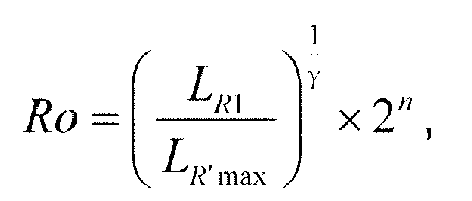


- Optionally, the brightness scaling coefficient of the brightness scaling unit is 1/K, and


- Optionally, the signal conversion device further includes a RGB proportion calculation unit, wherein the RGB proportion calculation unit is used for calculating the RGB proportional coefficients based on color coordinates for RGBW.
- Optionally, the color coordinates for RGBW include a R color coordinate R(xR,yR ), a G color coordinate G(xG ,yG ), a B color coordinate B(xB,yB ) and a W color coordinate W(xW,yW ).
- Equation for the RGB proportional coefficients is
- proportional coefficient for red

- proportional coefficient for green

- proportional coefficient for blue

- proportional coefficient for red

- proportional coefficient for green

- proportional coefficient for blue

- Optionally, the brightness detection unit generates RGB brightness substitute values based on the RGB proportional coefficients and the RGB brightness input values, and selects a minimum value from the RGB brightness substitute values as the W brightness input value.
- Optionally, the RGB brightness substitute values include a R brightness substitute value SR , a G brightness substitute value SG and a B brightness substitute value SB , and the RGB brightness substitute values are


- To achieve the above objective, the present invention provides a display device, including the above-described signal conversion device.
- To achieve the above objective, the present invention provides a signal conversion method, including the following steps of S1 to S3.
- Step S1, generating RGB brightness input values by performing a gamma conversion process on RGB input signals;
- Step S2, generating a W brightness input value based on RGB proportional coefficients and the RGB brightness input values; and
- Step S3, generating RGBW output signals based on the RGB proportional coefficients, the RGB brightness input values and the W brightness input value.
- According to the first aspect of the invention, the step S3 includes a step of generating RGBW brightness output values based on the RGB proportional coefficients, the RGB brightness input values and the W brightness input value, and a step of generating the RGBW output signals based on the RGBW brightness output values, and
the step S1 further includes a step of generating scaled maximum RGBW brightness values by performing a scaling process on maximum RGBW brightness values based on brightness scaling coefficients and a step of generating RGB brightness input values by performing a gamma conversion process on the RGB input signals based the scaled maximum RGBW brightness values, and
the step S3 further includes a step of generating the RGBW output signals based on the scaled maximum RGBW brightness values and the RGBW brightness output values. - According to the second aspect to the invention, the step S1 further includes a step of generating the RGB brightness input values by performing a gamma conversion process on the RGB input signals based on the maximum RGBW brightness values, and
the step S3 further includes a step of generating scaled RGBW brightness output values by performing a scaling process on the RGBW brightness output values based on the brightness scaling coefficients and a step of generating the RGBW output signals based on the maximum RGBW brightness values and the scaled RGBW brightness output values. - Optionally, the signal conversion method according to both aspects of the invention further includes a step of calculating the RGB proportional coefficients based on color coordinates for RGBW.
- Optionally, for both aspects of the invention, the step S2 further includes a step of generating RGB brightness substitute values based on the RGB proportional coefficients and the RGB brightness input values and obtaining the W brightness input value by selecting a minimum value from the RGB brightness substitute values.
- The present invention has the following beneficial effects:
In the technical solutions of the signal conversion device, the signal conversion method and the display device provided by the present invention, the gamma conversion unit is used for performing a gamma conversion process on RGB input signals and generating RGB brightness input values, the brightness detection unit is used for generating a W brightness input value based on RGB proportional coefficients and the RGB brightness input values and the brightness processing unit is used for generating RGBW output signals based on the RGB proportional coefficients, the RGB brightness input values and the W brightness input value. With the present invention, the brightness of a displayed image can be increased with a premise that the power consumption is not changed, so that the contrast of the displayed image is increased, and the display quality of the image is also improved. With the present invention, the power consumption of light emitting devices is reduced with a premise that the display brightness of a displayed image is not changed, so that the lifetime of the light emitting devices is increased, the cost of driving chips is reduced and thus the manufacturing cost of products is reduced. - Methods and apparatus according to the invention are as set out in the independent claims. Preferred forms are set out in the dependent claims.
The term embodiment used here below may be synonym of exemplary embodiment not part of the invention. -
-
Fig. 1 is a schematic diagram of a structure of a signal conversion device provided by Embodiment 1 of the present invention; -
Fig. 2 is a schematic diagram of a structure of a signal conversion device provided by Embodiment 2 of the present invention; -
Fig. 3 is a flowchart of a signal conversion method provided by Embodiment 4 of the present invention; -
Fig. 4 is a flowchart of a signal conversion method provided by Embodiment 5 of the present invention; and -
Fig. 5 is a flowchart of a signal conversion method provided by Embodiment 6 of the present invention. - To make those skilled in the art better understand the technical solutions of the present invention, the signal conversion device, the signal conversion method and the display device provided by the present invention will be described below in details in conjunction with the accompanying drawings.
-
Fig. 1 is a schematic diagram of a structure of a signal conversion device provided by Embodiment 1 of the present invention. As shown inFig. 1 , the device includes a gamma conversion unit 11, abrightness detection unit 12 and abrightness processing unit 13. The gamma conversion unit 11 is used for generating RGB brightness input values by performing a gamma conversion process on RGB input signals. Thebrightness detection unit 12 is used for generating a W brightness input value based on RGB proportional coefficients and the RGB brightness input values. Thebrightness processing unit 13 is used for generating RGBW output signals based on the RGB proportional coefficients, the RGB brightness input values and the W brightness input value. In this specification, R represents red, G represents green, B represents blue and W represents white. - In this embodiment, the
brightness processing unit 13 includes a brightness calculation unit 14 and a reversegamma conversion unit 15. The brightness calculation unit 14 is used for generating RGBW brightness output values based on the RGB proportional coefficients, the RGB brightness input values and the W brightness input value, and outputs the RGBW brightness output values to the reversegamma conversion unit 15. The reversegamma conversion unit 15 is used for generating RGBW output signals based on the RGBW brightness output values. - Further, the
brightness processing unit 13 also includes abrightness scaling unit 16. Thebrightness scaling unit 16 is used for performing a scaling process on maximum RGBW brightness values based on brightness scaling coefficients, generating scaled maximum RGBW brightness values, and outputting the scaled maximum RGBW brightness values to the gamma conversion unit 11 and the reversegamma conversion unit 15. Specifically, the maximum RGBW brightness values include a maximum R brightness value L R'max, a maximum G brightness value L G'max, a maximum B brightness value L B'max and a maximum W brightness value L W'max, and the scaled maximum RGBW brightness values include a scaled maximum R brightness value L Rmax, a scaled maximum G brightness value L Gmax, a scaled maximum B brightness value L Bmax, and a scaled maximum W brightness value L Wmax. The brightness scaling coefficient is K which is ranged from 0.5 to 2, and equations for the scaled maximum RGBW brightness values are L Rmax = K×L R'max, L Gmax = K×L G'max, L Bmax = K×L B'max and L Wmax = K×L W'max. - The gamma conversion unit 11 is specifically used for performing a gamma conversion process on the RGB input signals based on the scaled maximum RGBW brightness values, generating the RGB brightness input values, and outputting the RGB brightness input values to the
brightness detection unit 12 and the brightness calculation unit 14. Specifically, the RGB input signals include a R input signal Ri, a G input signal Gi and a B input signal Bi, and the RGB brightness input values include a R brightness input value LR , a G brightness input value LG and a B brightness input value LB, so that equations for the RGBW brightness input values are:


- In this embodiment, the
brightness detection unit 12 is specifically used for generating RGB brightness substitute values based on the RGB proportional coefficients and the RGB brightness input values, obtaining the W brightness input value by selecting a minimum value from the RGB brightness substitute values, and outputting the W brightness input value to the brightness calculation unit 14. Specifically, the RGB proportional coefficients include a R proportional coefficient RR , a G proportional coefficient RG and a B proportional coefficient RB , the RGB brightness substitute values include a R brightness substitute value SR , a G brightness substitute value SG and a B brightness substitute value SB , and the W brightness input value is LW . In this case, the RGB brightness substitute values are


- Optionally, the signal conversion device further includes a RGB
proportion calculation unit 17, wherein the RGBproportion calculation unit 17 is used for calculating the RGB proportional coefficients based on color coordinates for RGBW, and outputting the RGB proportional coefficients to thebrightness detection unit 12 and the brightness calculation unit 14. Specifically, the color coordinates for RGBW include a R color coordinate R(xR ,yR ), a G color coordinate G(xG,yG ), a B color coordinate B(xB ,yB ) and a W color coordinate W(xW ,yW ). In this case, Equation (1) for the RGB proportional coefficients may be: - proportional coefficient for red

- proportional coefficient for green

- proportional coefficient for blue

- In practical applications, other equations can be used for calculating the RGB proportional coefficients, for example, equation (2) for the RGB proportional coefficients may be:
- proportional coefficient for red

- proportional coefficient for green

- proportional coefficient for blue
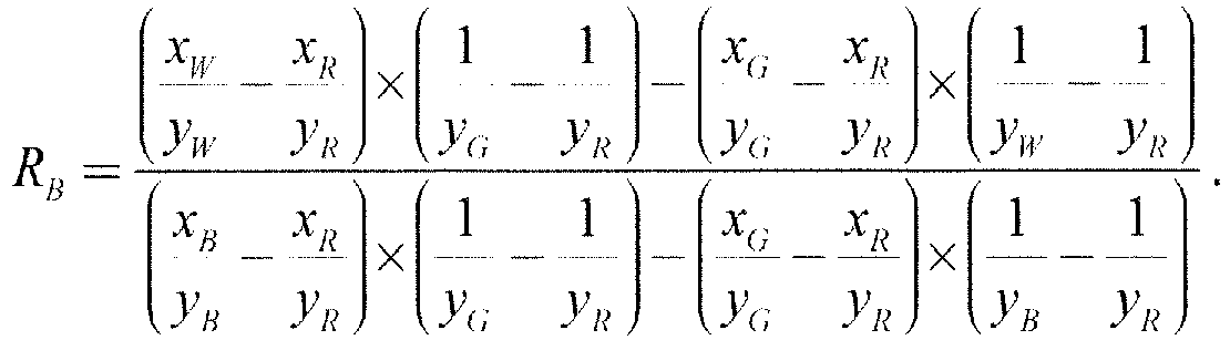
- The calculation results from the above equation (1) and (2) for the RGB proportional coefficients are the same.
- In this embodiment, the RGBW brightness output values include a R brightness output value LR', a G brightness output value LG' , a B brightness output value LB' , and a W brightness output value L W', then the equations for the RGBW brightness output values generated by the brightness calculation unit 14 are LR' = LR - LW × RR , LG' = LG - LW × RG , LB' = LB - LW × RB , LW' = LW.
- In this embodiment, the reverse
gamma conversion unit 15 is specifically used for generating the RGBW output signals based on the scaled maximum RGBW brightness values and the RGBW brightness output values. Specifically, the RGBW output signals include a R output signal Ro, a G output signal Go, a B output signal Bo and a W output signal Wo, then the equations for RGBW output signals are


- In the signal conversion device provided by the present embodiment, the gamma conversion unit is used for performing a gamma conversion process on RGB input signals and generating RGB brightness input values, the brightness detection unit is used for generating a W brightness input value based on RGB proportional coefficients and the RGB brightness input values, and the brightness processing unit is used for generating RGBW output signals based on the RGB proportional coefficients, the RGB brightness input values and the W brightness input value. With the present embodiment, the brightness of a displayed image can be increased with a premise that the power consumption is not changed, so that the contrast of the displayed image is increased, and the display quality of the image is also improved. With the present embodiment, the power consumption of light emitting devices is reduced with a premise that the display brightness of a displayed image is not changed, so that the lifetime of the light emitting devices is increased, the cost of driving chips is reduced and thus the manufacturing cost of products is reduced. Furthermore, with the present embodiment, the manufacturing cost of power supply can be reduced since the power consumption of light emitting devices is reduced, and thus the manufacturing cost of products is reduced. In addition, the brightness scaling unit can generate scaled maximum RGBW brightness values by performing the scaling process on the maximum RGBW brightness values based on the brightness scaling coefficients, so that the brightness of the displayed image can be further improved.
-
Fig. 2 is a schematic diagram of a structure of a signal conversion device provided by Embodiment 2 of the present invention. As shown inFig. 2 , the difference between the signal conversion device provided by this embodiment and that provided by Embodiment 1 is a brightness processing unit 21 including a brightness calculation unit 14, a brightness scaling unit 22 and a reverse gamma conversion unit 23. - In this embodiment, detailed descriptions of the gamma conversion unit 11, the
brightness detection unit 12, the brightness calculation unit 14 and the RGBproportion calculation unit 17 can refer to those of the Embodiment 1, and will not be redundantly described here. - In this embodiment, the brightness calculation unit 14 outputs RGBW brightness output values to the brightness scaling unit 22. The brightness scaling unit 22 is used for performing a scaling process on the RGBW brightness output values based on brightness scaling coefficients, generating scaled RGBW brightness output values, and outputting the scaled RGBW brightness output values to the reverse gamma conversion unit 23. Specifically, the scaled RGBW brightness output values include a scaled R brightness output value L R1 , a scaled G brightness output value L G1 , a scaled B brightness output value L B1 and a scaled W brightness output value L W1. Assuming that the brightness scaling coefficient of the brightness scaling unit 22 is 1/K, then the equations for the scaled RGBW brightness output values are


- The reverse gamma conversion unit 23 is used for generating RGBW output signals based on the maximum RGBW brightness values L R'max, L G'max, L B'max, L W'max and the scaled RGBW brightness output values. The equations for the RGBW output signals are


- In the signal conversion device provided by the present embodiment, the gamma conversion unit is used for performing a gamma conversion process on RGB input signals and generating RGB brightness input values, the brightness detection unit is used for generating a W brightness input value based on RGB proportional coefficients and the RGB brightness input values, and the brightness processing unit is used for generating RGBW output signals based on the RGB proportional coefficients, the RGB brightness input values and the W brightness input value. With the present embodiment, the brightness of a displayed image can be increased with a premise that the power consumption is not changed, so that the contrast of the displayed image is increased, and the display quality of the image is also improved. With the present embodiment, the power consumption of light emitting devices is reduced with a premise that the display brightness of a displayed image is not changed, so that the lifetime of the light emitting devices is increased, the cost of driving chips is reduced and thus the manufacturing cost of products is reduced. Furthermore, with the present embodiment, the manufacturing cost of power supply can be reduced since the power consumption of light emitting devices is reduced, and thus the manufacturing cost of products is reduced. In addition, the brightness scaling unit can generate scaled RGBW brightness output values by performing the scaling process on the RGBW brightness output values based on the brightness scaling coefficients, so that the brightness of the displayed image can be further improved.
- Embodiment 3 of the present invention provides a display device including a signal conversion device. In this embodiment, the signal conversion device may adopt the signal conversion device provided by Embodiment 1 or Embodiment 2, and will not be redundantly described here.
- In this embodiment, the display device may include an OLED display device or a liquid crystal display device.
- In the display device provided by the present embodiment, the gamma conversion unit is used for performing a gamma conversion process on RGB input signals and generating RGB brightness input values, the brightness detection unit is used for generating a W brightness input value based on RGB proportional coefficients and the RGB brightness input values, and the brightness processing unit is used for generating RGBW output signals based on the RGB proportional coefficients, the RGB brightness input values and the W brightness input value. With the present embodiment, the brightness of a displayed image can be increased with a premise that the power consumption is not changed, so that the contrast of the displayed image is increased, and the display quality of the image is also improved. With the present embodiment, the power consumption of light emitting devices is reduced with a premise that the display brightness of a displayed image is not changed, so that the lifetime of the light emitting devices is increased, the cost of driving chips is reduced and thus the manufacturing cost of products is reduced. Furthermore, with the present embodiment, the manufacturing cost of power supply can be reduced since the power consumption of light emitting devices is reduced, and thus the manufacturing cost of products is reduced. Specially, in a case where the display device is an OLED display device, with the present embodiment, the current flowing through light emitting devices can be effectively reduced, so that the power consumption of light emitting devices can be greatly reduced.
-
Fig. 3 is a flowchart of a signal conversion method provided by Embodiment 4 of the present invention. As shown inFig. 3 , the method includes the followingsteps 101 to 103. -
Step 101, RGB brightness input values are generated by performing a gamma conversion process on RGB input signals. -
Step 102, a W brightness input value is generated based on RGB proportional coefficients and the RGB brightness input values. -
Step 103, RGBW output signals are generated based on the RGB proportional coefficients, the RGB brightness input values and the W brightness input value. - For example, the
step 103 may include a step of generating RGBW brightness output values based on the RGB proportional coefficients, the RGB brightness input values and the W brightness input value, and a step of generating the RGBW output signals based on the RGBW brightness output values
The signal conversion method provided by the present embodiment includes generating the RGB brightness input values by performing the gamma conversion process on the RGB input signals, generating the W brightness input value based on the RGB proportional coefficients and the RGB brightness input values, and generating the RGBW output signals based on the RGB proportional coefficients, the RGB brightness input values and the W brightness input value. With the present embodiment, the brightness of a displayed image can be increased with a premise that the power consumption is not changed, so that the contrast of the displayed image is increased, and the display quality of the image is also improved. With the present embodiment, the power consumption of light emitting devices is reduced with a premise that the display brightness of a displayed image is not changed, so that the lifetime of the light emitting devices is increased, the cost of driving chips is reduced and thus the manufacturing cost of products is reduced. Furthermore, with the present embodiment, the manufacturing cost of power supply can be reduced since the power consumption of light emitting devices is reduced, and thus the manufacturing cost of products is reduced. -
Fig. 4 is flowchart of a signal conversion method provided by Embodiment 5 of the present invention. As shown inFig. 4 , the method includes the following steps of 201 to 206. -
Step 201, scaled maximum RGBW brightness values are generated by performing a scaling process on the maximum RGBW brightness values based on brightness scaling coefficients. -
Step 202, RGB proportional coefficients are calculated based on color coordinates for RGBW. -
Step 203, RGB brightness input values are generated by performing a gamma conversion process on RGB input values based on the scaled maximum RGBW brightness values. -
Step 204, RGB brightness substitute values are generated based on the RGB proportional coefficients and the RGB brightness input values, and a W brightness input value is obtained by selecting a minimum value from the RGB brightness substitute values. -
Step 205, RGBW brightness output values are generated based on the RGB proportional coefficients, the RGB brightness input values and the W brightness input values. -
Step 206, RGBW output signals are generated based on the scaled maximum RGBW brightness values and the RGBW brightness output values. - The signal conversion method provided by the present embodiment can be realized by using the signal conversion device provided by Embodiment 1 and the detailed descriptions of the terms and equations used in the present embodiment can refer to the description of Embodiment 1, and will not be redundantly described here.
- The signal conversion method provided by the present embodiment includes generating RGB brightness input values by performing a gamma conversion process on RGB input signals, generating a W brightness input value based on RGB proportional coefficients and the RGB brightness input values, and generating RGBW output signals based on the RGB proportional coefficients, the RGB brightness input values and the W brightness input value. With the present embodiment, the brightness of a displayed image can be increased with a premise that the power consumption is not changed, so that the contrast of the displayed image is increased, and the display quality of the image is also improved. With the present embodiment, the power consumption of light emitting devices is reduced with a premise that the display brightness of a displayed image is not changed, so that the lifetime of the light emitting devices is increased, the cost of driving chips is reduced and thus the manufacturing cost of products is reduced. Furthermore, with the present embodiment, the manufacturing cost of power supply can be reduced since the power consumption of light emitting devices is reduced, and thus the manufacturing cost of products is reduced. In addition, the scaled maximum RGBW brightness values are generated by performing a scaling process on the maximum RGBW brightness values based on the brightness scaling coefficients, so that the brightness of the displayed image can be further improved.
-
Fig. 5 is a flowchart of a signal conversion method provided by Embodiment 6 of the present invention. As shown inFig. 5 , the method includes the following steps of 301 to 306. -
Step 301, RGB proportional coefficients are calculated based on color coordinates for RGBW. -
Step 302, RGB brightness input values are generated by performing a gamma conversion process on RGB input signals based on the maximum RGBW brightness values. -
Step 303, RGB brightness substitute values are generated based on the RGB proportional coefficients and the RGB brightness input values, and a W brightness input value is obtained by selecting a minimum value from the RGB brightness substitute values. -
Step 304, RGBW brightness output values are generated based on the RGB proportional coefficients, the RGB brightness input values and the W brightness input value. -
Step 305, scaled RGBW brightness output values are generated by performing a scaling process on the RGBW brightness output values based on brightness scaling coefficients. -
Step 306, RGBW output signals are generated based on the maximum RGBW brightness values and the scaled RGBW brightness output values. - The signal conversion method provided by the present embodiment can be realized by using the signal conversion device provided by Embodiment 2 and the detailed descriptions of the terms and equations used in the present embodiment can refer to the description of Embodiment 2, and will not be redundantly described here.
- The signal conversion method provided by the present embodiment includes generating RGB brightness input values by performing a gamma conversion process on RGB input signals, generating a W brightness input value based on RGB proportional coefficients and the RGB brightness input values, and generating RGBW output signals based on the RGB proportional coefficients, the RGB brightness input values and the W brightness input value. With the present embodiment, the brightness of a displayed image can be increased with a premise that the power consumption is not changed, so that the contrast of the displayed image is increased, and the display quality of the image is also improved. With the present embodiment, the power consumption of light emitting devices is reduced with a premise that the display brightness of a displayed image is not changed, so that the lifetime of the light emitting devices is increased, the cost of driving chips is reduced and thus the manufacturing cost of products is reduced. Furthermore, with the present embodiment, the manufacturing cost of power supply can be reduced since the power consumption of light emitting devices is reduced, and thus the manufacturing cost of products is reduced. In addition, the scaled RGBW brightness output values are generated by performing a scaling process on the RGBW brightness output values based on the brightness scaling coefficients, so that the brightness of the displayed image can be further improved.
- It should be understood that the foregoing embodiments are merely the exemplary embodiments used for illustrating the principle of the present invention, but the present invention is not limited thereto. For those skilled in the art, various modifications and improvements can be made without departing from the scope of the present invention.
Claims (19)
- A signal conversion device, including a gamma conversion unit (11), a brightness detection unit (12) and a brightness processing unit (13), wherein
the gamma conversion unit (11) is used for performing a gamma conversion process on RGB input signals and generating RGB brightness input values;
the brightness detection unit (12) is used for generating a W brightness input value based on RGB proportional coefficients and the RGB brightness input values; and
the brightness processing unit (13) is used for generating RGBW output signals based on the RGB proportional coefficients, the RGB brightness input values and the W brightness input value,
wherein the brightness processing unit (13) includes a brightness calculation unit (14) and a reverse gamma conversion unit (15), wherein
the brightness calculation unit (14) generates RGBW brightness output values based on the RGB proportional coefficients, the RGB brightness input values and the W brightness input value, and outputs the RGBW brightness output values to the reverse gamma conversion unit (15); and
the reverse gamma conversion unit (15) generates the RGBW output signals based on the RGBW brightness output values,
characterized in that the brightness processing unit (13) further includes a brightness scaling unit (16) for performing a scaling process on the maximum RGBW brightness values based on brightness scaling coefficients, generating the scaled maximum RGBW brightness values, and outputting the scaled maximum RGBW brightness values to the gamma conversion unit (11) and the reverse gamma conversion unit (15), wherein
the gamma conversion unit (11) performs the gamma conversion process on the RGB input signals based on the scaled maximum RGBW brightness values, generates the RGB brightness input values, and outputs the RGB brightness input values to the brightness detection unit (12) and the brightness calculation unit (14); and
the reverse gamma conversion unit (15) generates the RGBW output signals based on the scaled maximum RGBW brightness values and the RGBW brightness output values. - A signal conversion device, including a gamma conversion unit (11), a brightness detection unit (12) and a brightness processing unit (13), wherein
the gamma conversion unit (11) is used for performing a gamma conversion process on RGB input signals and generating RGB brightness input values;
the brightness detection unit (12) is used for generating a W brightness input value based on RGB proportional coefficients and the RGB brightness input values; and
the brightness processing unit (13) is used for generating RGBW output signals based on the RGB proportional coefficients, the RGB brightness input values and the W brightness input value, characterized in that
the gamma conversion unit (11) performs the gamma conversion process on the RGB input signals based on the maximum RGBW brightness values, generates RGB brightness input values, and outputs the RGB brightness input values to the brightness detection unit (12) and the brightness calculation unit (14);
the brightness calculation unit (14) generates RGBW brightness output values based on the RGB proportional coefficients, the RGB brightness input values and the W brightness input value, and outputs the RGBW brightness output values to the brightness scaling unit (16);
the brightness scaling unit (16) performs a scaling process on the RGBW brightness output values based on brightness scaling coefficients, generates scaled RGBW brightness output values, and outputs the scaled RGBW brightness output values to the reverse gamma conversion unit (15), and
the reverse gamma conversion unit (15) generates the RGBW output signals based on the maximum RGBW brightness values and the scaled RGBW brightness output values. - The signal conversion device according to claim 1, wherein
the scaled maximum RGBW brightness values include a scaled maximum R brightness value L Rmax, a scaled maximum G brightness value L Gmax, a scaled maximum B brightness value L Bmax, and a scaled maximum W brightness value L Wmax ; the RGB input signals include a R input signal Ri, a G input signal Gi and a B input signal Bi; the RGB brightness input values include a R brightness input value LR , a G brightness input value LG and a B brightness input value LB ; and equations for the RGBW brightness input values are:

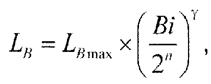
- The signal conversion device according to claim 3, wherein
the RGBW brightness output values include a R brightness output value LR' , a G brightness output value LG', a B brightness output value LB', and a W brightness output value LW' , the RGB proportional coefficients include a R proportional coefficient RR , a G proportional coefficient RG and a B proportional coefficient RB ; the RGBW brightness output values are LR' = LR - LW × RR , LG' = LG - LW × RG , LB' = LB - LW × RB , LW' = LW , respectively, where LW is the W brightness input value. - The signal conversion device according to claim 4, wherein
the RGBW output signals include a R output signal Ro, a G output signal Go, a B output signal Bo and a W output signal Wo ;
the RGBW output signals are


- The signal conversion device according to claim 5, wherein
the brightness scaling coefficient of the brightness scaling unit is K, the maximum R brightness value is L R'max, the maximum G brightness value is L G'max, the maximum B brightness value is L B'max and the maximum W brightness value is L W'max, wherein L Rmax = K×L R'max, L Gmax = K×L G'max, L Bmax = K×L B'max and L Wmax = K×L W'max, so that


- The signal conversion device according to claim 2, wherein
the RGB input signals include a R input signal Ri, a G input signal Gi and a B input signal Bi, and the RGB brightness input values include a R brightness input value LR , a G brightness input value LG and a B brightness input value LB ; equations for the RGB brightness input values are


- The signal conversion device according to claim 7, wherein
the RGBW brightness output values include a R brightness output value L R', a G brightness output value LG' , a B brightness output value LB' , and a W brightness output value L W', the RGB proportional coefficients include a R proportional coefficient R R', a G proportional coefficient RG and a B proportional coefficient RB ; the RGBW brightness output values are LR' = LR - LW × RR, LG' = LG - LW × RG , LB' = LB - LW × RB , LW' = LW , respectively, where LW is the W brightness input value. - The signal conversion device according to claim 8, wherein
the RGBW output signals include a R output signal Ro, a G output signal Go, a B output signal Bo and a W output signal Wo ;
the RGBW output signals are


- The signal conversion device according to claim 9, wherein
the brightness scaling coefficient of the brightness scaling unit (10) is 1/K, and


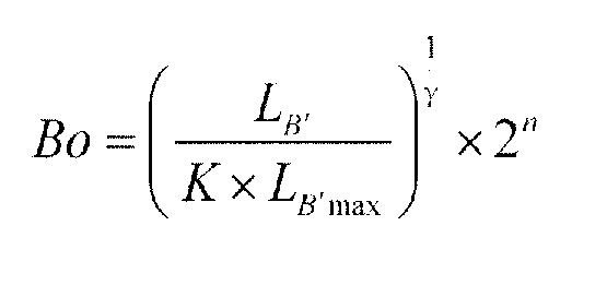

- The signal conversion device according to claim 4 or 8, further including a RGB proportion calculation unit (17), wherein the RGB proportion calculation unit (17) is used for calculating the RGB proportional coefficients based on color coordinates for RGBW.
- The signal conversion device according to claim 11, wherein
the color coordinates for RGBW include a R color coordinate R(xR,yR ), a G color coordinate G(xG,yG ), a B color coordinate B(xB,yB ) and a W color coordinate W(xW ,yW ).
Equation for the RGB proportional coefficients isproportional coefficient for red proportional coefficient for green
 proportional coefficient for blue
 proportional coefficient for red
 proportional coefficient for green
 proportional coefficient for blue
- The signal conversion device according to claim 12, wherein
the brightness detection unit (12) generates RGB brightness substitute values based on the RGB proportional coefficients and the RGB brightness input values, and selects a minimum value from the RGB brightness substitute values as the W brightness input value. - The signal conversion device according to claim 13, wherein
the RGB brightness substitute values include a R brightness substitute value SR, a G brightness substitute value SG and a B brightness substitute value SB ,
the RGB brightness substitute values are
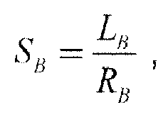
equation for the W brightness input value is LW = MIN(SR ,SG,SB ). - A display device, including the signal conversion device according to any one of claims 1 to 14.
- A signal conversion method, including the following steps of
step S1, generating RGB brightness input values by performing a gamma conversion process on RGB input signals;
step S2, generating a W brightness input value based on RGB proportional coefficients and the RGB brightness input values; and
step S3, generating RGBW output signals based on the RGB proportional coefficients, the RGB brightness input values and the W brightness input value,
wherein the step S3 including the following steps of
generating RGBW brightness output values based on the RGB proportional coefficients, the RGB brightness input values and the W brightness input value; and
generating the RGBW output signals based on the RGBW brightness output values,
characterized in that the step S1 further includes generating scaled maximum RGBW brightness values by performing a scaling process on maximum RGBW brightness values based on brightness scaling coefficients, and generating RGB brightness input values by performing a gamma conversion process on the RGB input signals based the scaled maximum RGBW brightness values, and
the step S3 further includes generating the RGBW output signals based on the scaled maximum RGBW brightness values and the RGBW brightness output values. - A signal conversion method, including the following steps of
step S1, generating RGB brightness input values by performing a gamma conversion process on RGB input signals;
step S2, generating a W brightness input value based on RGB proportional coefficients and the RGB brightness input values; and
step S3, generating RGBW output signals based on the RGB proportional coefficients, the RGB brightness input values and the W brightness input value, characterized in that
the step S1 further includes generating the RGB brightness input values by performing a gamma conversion process on the RGB input signals based on the maximum RGBW brightness values, and
the step S3 further includes generating scaled RGBW brightness output values by performing a scaling process on the RGBW brightness output values based on the brightness scaling coefficients; and generating the RGBW output signals based on the maximum RGBW brightness values and the scaled RGBW brightness output values. - The signal conversion method according to any one of claims 16 to 17, wherein
the RGB proportional coefficients are calculated based on color coordinates for RGBW. - The signal conversion method according to any one of claims 16 to 17, wherein
the step S2 further includes generating RGB brightness substitute values based on the RGB proportional coefficients and the RGB brightness input values and obtaining the W brightness input value by selecting a minimum value from the RGB brightness substitute values.
Applications Claiming Priority (2)
| Application Number | Priority Date | Filing Date | Title |
|---|---|---|---|
| CN201310741315.7A CN103700336B (en) | 2013-12-27 | 2013-12-27 | Chromacoder, method and display device |
| PCT/CN2014/078070 WO2015096366A1 (en) | 2013-12-27 | 2014-05-22 | Signal conversion device and method, and display device |
Publications (3)
| Publication Number | Publication Date |
|---|---|
| EP2953120A1 EP2953120A1 (en) | 2015-12-09 |
| EP2953120A4 EP2953120A4 (en) | 2016-10-12 |
| EP2953120B1 true EP2953120B1 (en) | 2019-11-06 |
Family
ID=50361847
Family Applications (1)
| Application Number | Title | Priority Date | Filing Date |
|---|---|---|---|
| EP14861139.5A Active EP2953120B1 (en) | 2013-12-27 | 2014-05-22 | Signal conversion device and method, and display device |
Country Status (4)
| Country | Link |
|---|---|
| US (1) | US9570015B2 (en) |
| EP (1) | EP2953120B1 (en) |
| CN (1) | CN103700336B (en) |
| WO (1) | WO2015096366A1 (en) |
Families Citing this family (15)
| Publication number | Priority date | Publication date | Assignee | Title |
|---|---|---|---|---|
| CN103700336B (en) | 2013-12-27 | 2017-03-01 | 京东方科技集团股份有限公司 | Chromacoder, method and display device |
| JP2015222400A (en) * | 2014-05-23 | 2015-12-10 | 株式会社ジャパンディスプレイ | Display device, display system, and image processing circuit |
| CN105336288B (en) * | 2014-08-15 | 2018-02-16 | Tcl集团股份有限公司 | A kind of rgb signal is to the conversion method of RGBW signals, device and TV |
| CN104410849B (en) * | 2014-10-21 | 2016-06-29 | 深圳市华星光电技术有限公司 | Image processing method and device |
| US9401107B2 (en) | 2014-12-31 | 2016-07-26 | Shenzhen China Star Optoelectronics Technology Co., Ltd. | Image data processing method and device thereof |
| CN104486608B (en) * | 2014-12-31 | 2016-07-20 | 深圳市华星光电技术有限公司 | Image processing method and device |
| CN104575405B (en) * | 2015-02-04 | 2017-08-25 | 京东方科技集团股份有限公司 | A kind of method, the display device of adjusting display device backlight illumination |
| CN104952423A (en) * | 2015-07-03 | 2015-09-30 | 深圳市华星光电技术有限公司 | Image display method and system |
| CN105263009B (en) * | 2015-09-14 | 2017-12-15 | 深圳市华星光电技术有限公司 | A kind of self-adaptive conversion method of image |
| CN105575351B (en) | 2016-02-26 | 2018-09-14 | 京东方科技集团股份有限公司 | A kind of gray scale voltage adjustment method, device and display device |
| CN105895005A (en) * | 2016-06-29 | 2016-08-24 | 京东方科技集团股份有限公司 | Display driving chip, display substrate, display device and display driving method |
| CN108898987B (en) * | 2018-07-31 | 2021-04-27 | 京东方科技集团股份有限公司 | Gray scale conversion method, gray scale conversion device and display device |
| JP2020144198A (en) * | 2019-03-05 | 2020-09-10 | 株式会社ジャパンディスプレイ | Display device |
| WO2020210740A1 (en) * | 2019-04-11 | 2020-10-15 | PixelDisplay Inc. | Method and apparatus of a multi-modal illumination and display for improved color rendering, power efficiency, health and eye-safety |
| CN111048052A (en) * | 2019-12-30 | 2020-04-21 | 深圳Tcl新技术有限公司 | Display control method, device, device and computer storage medium |
Family Cites Families (10)
| Publication number | Priority date | Publication date | Assignee | Title |
|---|---|---|---|---|
| KR100943273B1 (en) * | 2003-05-07 | 2010-02-23 | 삼성전자주식회사 | 4-color conversion method and apparatus and organic light emitting display device using the same |
| CN101171594A (en) * | 2005-04-04 | 2008-04-30 | 克雷沃耶提公司 | Systems and methods for implementing low-cost full-range mapping algorithms |
| JP4509159B2 (en) * | 2007-09-27 | 2010-07-21 | シャープ株式会社 | Transmission type liquid crystal display device |
| JP5190731B2 (en) * | 2007-10-23 | 2013-04-24 | Nltテクノロジー株式会社 | Image display device, image display method used in the image display device, and liquid crystal display device |
| JP5278730B2 (en) * | 2008-04-16 | 2013-09-04 | Nltテクノロジー株式会社 | CONTROLLER, HOLD TYPE DISPLAY, ELECTRONIC DEVICE, SIGNAL ADJUSTMENT METHOD FOR HOLD TYPE DISPLAY |
| US9153205B2 (en) * | 2011-03-16 | 2015-10-06 | Panasonic Intellectual Property Management Co., Ltd. | Display device having a generator for generating RGBW signals based on upper and lower limit value calculator and display method thereof |
| US9153200B2 (en) * | 2011-05-13 | 2015-10-06 | Samsung Display Co., Ltd. | Method for selecting backlight color values |
| CN103218988B (en) * | 2013-03-25 | 2015-02-25 | 京东方科技集团股份有限公司 | Method and device for image conversion from RGB signal to RGBW signal |
| KR20150022235A (en) * | 2013-08-22 | 2015-03-04 | 삼성디스플레이 주식회사 | Color compensation device and display device using the same, and color compensation method |
| CN103700336B (en) * | 2013-12-27 | 2017-03-01 | 京东方科技集团股份有限公司 | Chromacoder, method and display device |
-
2013
- 2013-12-27 CN CN201310741315.7A patent/CN103700336B/en not_active Expired - Fee Related
-
2014
- 2014-05-22 EP EP14861139.5A patent/EP2953120B1/en active Active
- 2014-05-22 US US14/422,819 patent/US9570015B2/en not_active Expired - Fee Related
- 2014-05-22 WO PCT/CN2014/078070 patent/WO2015096366A1/en not_active Ceased
Non-Patent Citations (1)
| Title |
|---|
| None * |
Also Published As
| Publication number | Publication date |
|---|---|
| WO2015096366A1 (en) | 2015-07-02 |
| CN103700336A (en) | 2014-04-02 |
| EP2953120A4 (en) | 2016-10-12 |
| EP2953120A1 (en) | 2015-12-09 |
| US20160042698A1 (en) | 2016-02-11 |
| US9570015B2 (en) | 2017-02-14 |
| CN103700336B (en) | 2017-03-01 |
Similar Documents
| Publication | Publication Date | Title |
|---|---|---|
| EP2953120B1 (en) | Signal conversion device and method, and display device | |
| US9564085B2 (en) | Selective dimming to reduce power of a light emitting display device | |
| CN104299598B (en) | Three-color data to four-color data conversion system and conversion method | |
| US8405675B2 (en) | Device and method for converting three color values to four color values | |
| US9035980B2 (en) | Method of using a pixel to display an image | |
| CN102800297B (en) | Method for processing image signal | |
| JP5124051B1 (en) | Display device | |
| CN103489400B (en) | Processor and method for converting RGB data signal into RGBW data signal | |
| US9589534B2 (en) | System and method for converting RGB data to WRGB data | |
| CN110085174B (en) | Method and device for reducing power consumption of display | |
| US10229642B2 (en) | Liquid crystal display device | |
| CN102034446A (en) | Liquid crystal display device and driving method thereof | |
| CN101984487A (en) | Driving method of active matrix organic light emitting diode display panel | |
| US8314820B2 (en) | Backlight adjustment device of a display and method thereof | |
| KR101859481B1 (en) | Display device and method for driving the same | |
| US9355614B2 (en) | Image quality processing method and display device using the same | |
| US20090174730A1 (en) | Data driving apparatus and method thereof | |
| JP6551230B2 (en) | Signal generation device and image display device | |
| US9552763B2 (en) | Data conversion unit and method of converting data | |
| KR20150073700A (en) | Organic light emitting display and driving method thereof | |
| US9569999B2 (en) | Signal generation apparatus, signal generation program, signal generation method, and image display apparatus | |
| KR20170039783A (en) | Method of display apparatus | |
| KR20120139092A (en) | Self light emission display device and its driving method | |
| KR101927862B1 (en) | Image display device and method of driving the same | |
| KR102379774B1 (en) | Image processing method, image processing circuit and display device using the same |
Legal Events
| Date | Code | Title | Description |
|---|---|---|---|
| PUAI | Public reference made under article 153(3) epc to a published international application that has entered the european phase |
Free format text: ORIGINAL CODE: 0009012 |
|
| 17P | Request for examination filed |
Effective date: 20150519 |
|
| AK | Designated contracting states |
Kind code of ref document: A1 Designated state(s): AL AT BE BG CH CY CZ DE DK EE ES FI FR GB GR HR HU IE IS IT LI LT LU LV MC MK MT NL NO PL PT RO RS SE SI SK SM TR |
|
| AX | Request for extension of the european patent |
Extension state: BA ME |
|
| A4 | Supplementary search report drawn up and despatched |
Effective date: 20160912 |
|
| RIC1 | Information provided on ipc code assigned before grant |
Ipc: G09G 3/32 20060101ALI20160906BHEP Ipc: G09G 3/20 20060101AFI20160906BHEP |
|
| DAX | Request for extension of the european patent (deleted) | ||
| REG | Reference to a national code |
Ref country code: DE Ref legal event code: R079 Ref document number: 602014056538 Country of ref document: DE Free format text: PREVIOUS MAIN CLASS: G09G0003200000 Ipc: G09G0003320800 |
|
| GRAP | Despatch of communication of intention to grant a patent |
Free format text: ORIGINAL CODE: EPIDOSNIGR1 |
|
| STAA | Information on the status of an ep patent application or granted ep patent |
Free format text: STATUS: GRANT OF PATENT IS INTENDED |
|
| RIC1 | Information provided on ipc code assigned before grant |
Ipc: G09G 5/04 20060101ALI20190417BHEP Ipc: G09G 3/20 20060101ALI20190417BHEP Ipc: G09G 3/3208 20160101AFI20190417BHEP Ipc: G09G 5/06 20060101ALI20190417BHEP Ipc: G09G 3/34 20060101ALI20190417BHEP |
|
| INTG | Intention to grant announced |
Effective date: 20190520 |
|
| GRAS | Grant fee paid |
Free format text: ORIGINAL CODE: EPIDOSNIGR3 |
|
| GRAA | (expected) grant |
Free format text: ORIGINAL CODE: 0009210 |
|
| STAA | Information on the status of an ep patent application or granted ep patent |
Free format text: STATUS: THE PATENT HAS BEEN GRANTED |
|
| AK | Designated contracting states |
Kind code of ref document: B1 Designated state(s): AL AT BE BG CH CY CZ DE DK EE ES FI FR GB GR HR HU IE IS IT LI LT LU LV MC MK MT NL NO PL PT RO RS SE SI SK SM TR |
|
| REG | Reference to a national code |
Ref country code: GB Ref legal event code: FG4D |
|
| REG | Reference to a national code |
Ref country code: CH Ref legal event code: EP Ref country code: AT Ref legal event code: REF Ref document number: 1199866 Country of ref document: AT Kind code of ref document: T Effective date: 20191115 |
|
| REG | Reference to a national code |
Ref country code: IE Ref legal event code: FG4D |
|
| REG | Reference to a national code |
Ref country code: DE Ref legal event code: R096 Ref document number: 602014056538 Country of ref document: DE |
|
| REG | Reference to a national code |
Ref country code: NL Ref legal event code: MP Effective date: 20191106 |
|
| REG | Reference to a national code |
Ref country code: LT Ref legal event code: MG4D |
|
| PG25 | Lapsed in a contracting state [announced via postgrant information from national office to epo] |
Ref country code: LT Free format text: LAPSE BECAUSE OF FAILURE TO SUBMIT A TRANSLATION OF THE DESCRIPTION OR TO PAY THE FEE WITHIN THE PRESCRIBED TIME-LIMIT Effective date: 20191106 Ref country code: SE Free format text: LAPSE BECAUSE OF FAILURE TO SUBMIT A TRANSLATION OF THE DESCRIPTION OR TO PAY THE FEE WITHIN THE PRESCRIBED TIME-LIMIT Effective date: 20191106 Ref country code: LV Free format text: LAPSE BECAUSE OF FAILURE TO SUBMIT A TRANSLATION OF THE DESCRIPTION OR TO PAY THE FEE WITHIN THE PRESCRIBED TIME-LIMIT Effective date: 20191106 Ref country code: NL Free format text: LAPSE BECAUSE OF FAILURE TO SUBMIT A TRANSLATION OF THE DESCRIPTION OR TO PAY THE FEE WITHIN THE PRESCRIBED TIME-LIMIT Effective date: 20191106 Ref country code: BG Free format text: LAPSE BECAUSE OF FAILURE TO SUBMIT A TRANSLATION OF THE DESCRIPTION OR TO PAY THE FEE WITHIN THE PRESCRIBED TIME-LIMIT Effective date: 20200206 Ref country code: FI Free format text: LAPSE BECAUSE OF FAILURE TO SUBMIT A TRANSLATION OF THE DESCRIPTION OR TO PAY THE FEE WITHIN THE PRESCRIBED TIME-LIMIT Effective date: 20191106 Ref country code: GR Free format text: LAPSE BECAUSE OF FAILURE TO SUBMIT A TRANSLATION OF THE DESCRIPTION OR TO PAY THE FEE WITHIN THE PRESCRIBED TIME-LIMIT Effective date: 20200207 Ref country code: NO Free format text: LAPSE BECAUSE OF FAILURE TO SUBMIT A TRANSLATION OF THE DESCRIPTION OR TO PAY THE FEE WITHIN THE PRESCRIBED TIME-LIMIT Effective date: 20200206 Ref country code: PT Free format text: LAPSE BECAUSE OF FAILURE TO SUBMIT A TRANSLATION OF THE DESCRIPTION OR TO PAY THE FEE WITHIN THE PRESCRIBED TIME-LIMIT Effective date: 20200306 Ref country code: PL Free format text: LAPSE BECAUSE OF FAILURE TO SUBMIT A TRANSLATION OF THE DESCRIPTION OR TO PAY THE FEE WITHIN THE PRESCRIBED TIME-LIMIT Effective date: 20191106 |
|
| PG25 | Lapsed in a contracting state [announced via postgrant information from national office to epo] |
Ref country code: RS Free format text: LAPSE BECAUSE OF FAILURE TO SUBMIT A TRANSLATION OF THE DESCRIPTION OR TO PAY THE FEE WITHIN THE PRESCRIBED TIME-LIMIT Effective date: 20191106 Ref country code: HR Free format text: LAPSE BECAUSE OF FAILURE TO SUBMIT A TRANSLATION OF THE DESCRIPTION OR TO PAY THE FEE WITHIN THE PRESCRIBED TIME-LIMIT Effective date: 20191106 Ref country code: IS Free format text: LAPSE BECAUSE OF FAILURE TO SUBMIT A TRANSLATION OF THE DESCRIPTION OR TO PAY THE FEE WITHIN THE PRESCRIBED TIME-LIMIT Effective date: 20200306 |
|
| PG25 | Lapsed in a contracting state [announced via postgrant information from national office to epo] |
Ref country code: AL Free format text: LAPSE BECAUSE OF FAILURE TO SUBMIT A TRANSLATION OF THE DESCRIPTION OR TO PAY THE FEE WITHIN THE PRESCRIBED TIME-LIMIT Effective date: 20191106 |
|
| PG25 | Lapsed in a contracting state [announced via postgrant information from national office to epo] |
Ref country code: CZ Free format text: LAPSE BECAUSE OF FAILURE TO SUBMIT A TRANSLATION OF THE DESCRIPTION OR TO PAY THE FEE WITHIN THE PRESCRIBED TIME-LIMIT Effective date: 20191106 Ref country code: RO Free format text: LAPSE BECAUSE OF FAILURE TO SUBMIT A TRANSLATION OF THE DESCRIPTION OR TO PAY THE FEE WITHIN THE PRESCRIBED TIME-LIMIT Effective date: 20191106 Ref country code: ES Free format text: LAPSE BECAUSE OF FAILURE TO SUBMIT A TRANSLATION OF THE DESCRIPTION OR TO PAY THE FEE WITHIN THE PRESCRIBED TIME-LIMIT Effective date: 20191106 Ref country code: EE Free format text: LAPSE BECAUSE OF FAILURE TO SUBMIT A TRANSLATION OF THE DESCRIPTION OR TO PAY THE FEE WITHIN THE PRESCRIBED TIME-LIMIT Effective date: 20191106 Ref country code: DK Free format text: LAPSE BECAUSE OF FAILURE TO SUBMIT A TRANSLATION OF THE DESCRIPTION OR TO PAY THE FEE WITHIN THE PRESCRIBED TIME-LIMIT Effective date: 20191106 |
|
| REG | Reference to a national code |
Ref country code: DE Ref legal event code: R097 Ref document number: 602014056538 Country of ref document: DE |
|
| REG | Reference to a national code |
Ref country code: AT Ref legal event code: MK05 Ref document number: 1199866 Country of ref document: AT Kind code of ref document: T Effective date: 20191106 |
|
| PG25 | Lapsed in a contracting state [announced via postgrant information from national office to epo] |
Ref country code: SK Free format text: LAPSE BECAUSE OF FAILURE TO SUBMIT A TRANSLATION OF THE DESCRIPTION OR TO PAY THE FEE WITHIN THE PRESCRIBED TIME-LIMIT Effective date: 20191106 Ref country code: SM Free format text: LAPSE BECAUSE OF FAILURE TO SUBMIT A TRANSLATION OF THE DESCRIPTION OR TO PAY THE FEE WITHIN THE PRESCRIBED TIME-LIMIT Effective date: 20191106 |
|
| PLBE | No opposition filed within time limit |
Free format text: ORIGINAL CODE: 0009261 |
|
| STAA | Information on the status of an ep patent application or granted ep patent |
Free format text: STATUS: NO OPPOSITION FILED WITHIN TIME LIMIT |
|
| 26N | No opposition filed |
Effective date: 20200807 |
|
| PG25 | Lapsed in a contracting state [announced via postgrant information from national office to epo] |
Ref country code: AT Free format text: LAPSE BECAUSE OF FAILURE TO SUBMIT A TRANSLATION OF THE DESCRIPTION OR TO PAY THE FEE WITHIN THE PRESCRIBED TIME-LIMIT Effective date: 20191106 Ref country code: SI Free format text: LAPSE BECAUSE OF FAILURE TO SUBMIT A TRANSLATION OF THE DESCRIPTION OR TO PAY THE FEE WITHIN THE PRESCRIBED TIME-LIMIT Effective date: 20191106 |
|
| PG25 | Lapsed in a contracting state [announced via postgrant information from national office to epo] |
Ref country code: IT Free format text: LAPSE BECAUSE OF FAILURE TO SUBMIT A TRANSLATION OF THE DESCRIPTION OR TO PAY THE FEE WITHIN THE PRESCRIBED TIME-LIMIT Effective date: 20191106 Ref country code: CH Free format text: LAPSE BECAUSE OF NON-PAYMENT OF DUE FEES Effective date: 20200531 Ref country code: LI Free format text: LAPSE BECAUSE OF NON-PAYMENT OF DUE FEES Effective date: 20200531 Ref country code: MC Free format text: LAPSE BECAUSE OF FAILURE TO SUBMIT A TRANSLATION OF THE DESCRIPTION OR TO PAY THE FEE WITHIN THE PRESCRIBED TIME-LIMIT Effective date: 20191106 |
|
| REG | Reference to a national code |
Ref country code: BE Ref legal event code: MM Effective date: 20200531 |
|
| GBPC | Gb: european patent ceased through non-payment of renewal fee |
Effective date: 20200522 |
|
| PG25 | Lapsed in a contracting state [announced via postgrant information from national office to epo] |
Ref country code: LU Free format text: LAPSE BECAUSE OF NON-PAYMENT OF DUE FEES Effective date: 20200522 |
|
| PG25 | Lapsed in a contracting state [announced via postgrant information from national office to epo] |
Ref country code: IE Free format text: LAPSE BECAUSE OF NON-PAYMENT OF DUE FEES Effective date: 20200522 Ref country code: GB Free format text: LAPSE BECAUSE OF NON-PAYMENT OF DUE FEES Effective date: 20200522 Ref country code: FR Free format text: LAPSE BECAUSE OF NON-PAYMENT OF DUE FEES Effective date: 20200531 |
|
| PG25 | Lapsed in a contracting state [announced via postgrant information from national office to epo] |
Ref country code: BE Free format text: LAPSE BECAUSE OF NON-PAYMENT OF DUE FEES Effective date: 20200531 |
|
| PG25 | Lapsed in a contracting state [announced via postgrant information from national office to epo] |
Ref country code: TR Free format text: LAPSE BECAUSE OF FAILURE TO SUBMIT A TRANSLATION OF THE DESCRIPTION OR TO PAY THE FEE WITHIN THE PRESCRIBED TIME-LIMIT Effective date: 20191106 Ref country code: MT Free format text: LAPSE BECAUSE OF FAILURE TO SUBMIT A TRANSLATION OF THE DESCRIPTION OR TO PAY THE FEE WITHIN THE PRESCRIBED TIME-LIMIT Effective date: 20191106 Ref country code: CY Free format text: LAPSE BECAUSE OF FAILURE TO SUBMIT A TRANSLATION OF THE DESCRIPTION OR TO PAY THE FEE WITHIN THE PRESCRIBED TIME-LIMIT Effective date: 20191106 |
|
| PG25 | Lapsed in a contracting state [announced via postgrant information from national office to epo] |
Ref country code: MK Free format text: LAPSE BECAUSE OF FAILURE TO SUBMIT A TRANSLATION OF THE DESCRIPTION OR TO PAY THE FEE WITHIN THE PRESCRIBED TIME-LIMIT Effective date: 20191106 |
|
| PGFP | Annual fee paid to national office [announced via postgrant information from national office to epo] |
Ref country code: DE Payment date: 20250519 Year of fee payment: 12 |