EP2941971A1 - Appareil et procédé de collecte d'énergie mécanique incorporé dans une chaussure - Google Patents
Appareil et procédé de collecte d'énergie mécanique incorporé dans une chaussure Download PDFInfo
- Publication number
- EP2941971A1 EP2941971A1 EP15166787.0A EP15166787A EP2941971A1 EP 2941971 A1 EP2941971 A1 EP 2941971A1 EP 15166787 A EP15166787 A EP 15166787A EP 2941971 A1 EP2941971 A1 EP 2941971A1
- Authority
- EP
- European Patent Office
- Prior art keywords
- footwear
- turbine
- reservoir
- energy harvesting
- pump
- Prior art date
- Legal status (The legal status is an assumption and is not a legal conclusion. Google has not performed a legal analysis and makes no representation as to the accuracy of the status listed.)
- Withdrawn
Links
- 238000003306 harvesting Methods 0.000 title claims abstract description 23
- 238000000034 method Methods 0.000 title claims description 10
- 238000004891 communication Methods 0.000 claims abstract description 7
- 239000012530 fluid Substances 0.000 claims abstract description 6
- 230000005611 electricity Effects 0.000 claims description 8
- 230000006835 compression Effects 0.000 claims description 2
- 238000007906 compression Methods 0.000 claims description 2
- 230000001419 dependent effect Effects 0.000 claims description 2
- 238000003860 storage Methods 0.000 description 10
- 238000011144 upstream manufacturing Methods 0.000 description 5
- 238000010586 diagram Methods 0.000 description 3
- 230000001133 acceleration Effects 0.000 description 2
- 239000003550 marker Substances 0.000 description 2
- 230000003287 optical effect Effects 0.000 description 2
- 238000012935 Averaging Methods 0.000 description 1
- 238000010438 heat treatment Methods 0.000 description 1
- 238000004519 manufacturing process Methods 0.000 description 1
- 239000013307 optical fiber Substances 0.000 description 1
- 230000003071 parasitic effect Effects 0.000 description 1
- 238000005086 pumping Methods 0.000 description 1
- 230000001225 therapeutic effect Effects 0.000 description 1
- 238000005303 weighing Methods 0.000 description 1
Images


Classifications
-
- A—HUMAN NECESSITIES
- A43—FOOTWEAR
- A43B—CHARACTERISTIC FEATURES OF FOOTWEAR; PARTS OF FOOTWEAR
- A43B13/00—Soles; Sole-and-heel integral units
- A43B13/14—Soles; Sole-and-heel integral units characterised by the constructive form
- A43B13/18—Resilient soles
- A43B13/20—Pneumatic soles filled with a compressible fluid, e.g. air, gas
- A43B13/203—Pneumatic soles filled with a compressible fluid, e.g. air, gas provided with a pump or valve
-
- A—HUMAN NECESSITIES
- A43—FOOTWEAR
- A43B—CHARACTERISTIC FEATURES OF FOOTWEAR; PARTS OF FOOTWEAR
- A43B3/00—Footwear characterised by the shape or the use
- A43B3/34—Footwear characterised by the shape or the use with electrical or electronic arrangements
- A43B3/38—Footwear characterised by the shape or the use with electrical or electronic arrangements with power sources
- A43B3/42—Footwear characterised by the shape or the use with electrical or electronic arrangements with power sources where power is generated by conversion of mechanical movement to electricity, e.g. by piezoelectric means
Definitions
- the present invention relates to an apparatus set in footwear for the purpose of generating electricity for the purposes of powering electrical accessories carried by the wearer, and the method therefore.
- the problem relates to the generation of electricity by a person while walking, to provide electrical energy to drive personal electronic equipment carried by the person.
- an energy harvesting system for footwear comprising a first gaseous pump formed at the sole of the footwear and a second gaseous pump formed at the heel of the footwear.
- a reservoir is mounted to the upper of footwear in fluid communication with and downstream of the first and second pumps and adapted to receive pressurized gas exiting from the pumps.
- a turbine having an output shaft is mounted on the footwear upper, in fluid communication with and downstream of the reservoir.
- the turbine includes an inlet port section for receiving the pressurized gas from the reservoir, when a predetermined pressure threshold is attained in the reservoir, so as to activate the turbine; and an electrical generator mounted on the upper, downstream of the turbine and disengageably connected with the turbine output shaft so that the generator is engaged by the shaft when a predetermined shaft velocity threshold has been attained whereby electricity may be generated in order to energize or be stored by a device worn by the bearer of the footwear.
- the turbine inlet port section includes a diffuser and the rotor includes an input shaft coaxial with the output shaft.
- the turbine includes eight stages.
- a multistage, axial turbine for converting energy from a pressurized gas to mechanical energy which may be used within a footwear energy harvesting system.
- the turbine includes a casing having an inlet and an outlet at axially aligned opposite ends of the casing, and the casing houses a cylindrical hollow stator and an elongated rotor concentric with the stator.
- the rotor includes a plurality of stages of radially extending rotor blades spaced circumferentially in each stage, while the stator is provided with rows of radially extending stator vanes circumferentially spaced apart in each row and the rows are located inter-stage of the rotor blade stages.
- the casing includes a diffuser at the inlet provided to receive the pressurized gas and to direct it to the rotor and stator.
- the casing is provided with bearings at the inlet and the outlet and the rotor has an upstream shaft and an output shaft coaxial with the upstream shaft and the shafts rotating freely while being supported in the respective bearings.
- the turbine For use in footwear in order to harvest energy from walking the turbine must miniaturized in order to fit in a footwear.
- the axial turbine is miniaturized for use within a footwear energy harvesting system.
- the turbine may have around eight stages.
- the turbine might also have eight stages and the rotor blades increase in height from 0.692 mm at the upstream stage to 1.004 mm at the downstream 8 th stage.
- a method of harvesting energy from footwear comprising the steps of compressing a gas in a chamber at the sole of the footwear transferring the compressed gas to a second chamber at the heel of the footwear; further compressing the gas in the second chamber; transferring the compressed gas from the second chamber to a reservoir; repeating the compression steps until the pressure in the reservoir has reached a threshold level; once the pressure level in the reservoir has reached the threshold level, passing the pressurized gas through a turbine to convert the energy from the pressurized gas to mechanical energy by rotating the turbine rotor and dependent shaft to reach a speed threshold; once the speed threshold of the shaft has been reached, engaging the shaft with an electric generator; storing the electricity and/or driving a device carried by the bearer of the footwear.
- FIG. 1 there is shown a work boot 10 having a heel 12 and a sole 14 along with an upper 16.
- the heel 12 has a heel plate 13 that is hinged, at its forward portion, at 18 to the boot.
- the heel plate 12 can pivot in a vertical plane about an axis normal to the vertical plane at the hinge 18.
- a flexible, impermeable bellows wall 20 defines a bellows chamber 21 between the boot and the pivoting heel 12.
- a oneway air inlet valve 20a is defined in the flexible wall 20.
- outsole 14a pivots about a hinge 22 in the toe region of the boot 10.
- the outsole 14 can pivot in a vertical plane about an axis at the hinge 22 that is normal to the vertical plane.
- a flexible, impermeable bellows wall 24 is provided defining a bellows chamber 25 between the boot and the pivoting outsole 14a.
- a oneway air inlet valve 25a is provided in the bellows wall 24, which otherwise is airtight.
- An air conduit 32 communicates the bellows chamber 25 with the bellows chamber 21.
- a one-way check valve 31 interrupts the conduit 32 to prevent the air from returning into the chamber 25.
- the precompressed air is now compressed to between 25-30 psi (172 kPa - 207 kPa); partly because of the smaller heel area providing a smaller chamber 21.
- the compressed air from the bellows chamber 21 passes through the conduit 28 to the reservoir 26, interrupted by a one-way check valve 30.
- the reservoir 26, mounted on the side of the upper 16 of the boot 10, typically has a capacity of 12 in 3 (197 cm 3 ), in order to provide storage capacity for the compressed air before it is released to the turbine 34.
- An air conduit 36 communicates the reservoir 26 to the turbine 34.
- the air conduit 36 is interrupted by a pressure control valve 38. It was determined that the ideal pressure for delivering the air to the turbine 34 is between 30 and 40 psi, but the latter is preferred.
- a control panel 40 is mounted to the side of the upper 16 and preferably between inner-layers forming the upper 16.
- An air-line 42 extends between the valve 38 and a pressure regulator 43 on the control panel 40.
- the valve 38 is opened by the pressure regulator, when the pressure threshold e.g. 40 psi is attained.
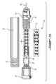
- the turbine 34 may be approximately 51 mm long and less than 10 mm in diameter.
- the turbine is considered to be minituarised and other similar dimensions are considered to be equivalent.
- the criteria is that it must be able to be mounted to the upper 16 of boot 10.
- the turbine 34 is made up of a tubular casing 60 enclosing a cylindrical stator 70, in the form of a sleeve, with a concentric, elongated rotor 68.
- the rotor 68 includes a coaxial shaft 66 extending upstream and downstream thereof.
- An inlet cap 62 is threaded onto the external threads 61 of the tubular casing 60.
- an outlet cap 64 At the other end of the casing 60 is an outlet cap 64 with it external threads 82 adapted to engage the internal threads 63 of the tubular casing 60.
- the downstream or output portion of shaft 66 is supported by the inner race 80 of a bearing 81 mounted within the outlet cap 64.
- an inlet diffuser 72 At the other end of the casing 60, an inlet diffuser 72, in the form of a cylindrical housing, has an inner race 78, part of an integrated bearing 79, supporting the upstream end of shaft 66.
- the rotor 68 mounts several stages of rotor blades 84. Preferably eight stages are provided.
- the blades 84 extend radially outwardly from the core surface of the rotor 68 and are spaced apart circumferentially, equally in each stage.
- the stator 70 is fabricated in semi-cylindrical segments 70a and 70b, forming a sleeve which is mounted within the casing 60 and is concentric with the rotor 68. In certain conditions the stator may be in three segments. As shown in Figs. 6a and 6b , the stator 70 has a plurality of rows of vanes 86, each extending radially inwardly. The vanes 86 are spaced apart equally in each row and the rows are inter stage with the rotor stages. Back to Figs.
- the diffuser 72 includes an annular array of bores 74 arranged to pass the compressed air into the turbine 34.
- the rotor 68 and stator 70 will be described in more detail herein below.
- air entering the turbine 34 will cause the shaft 66 to rotate at an increasingly higher speed, when the shaft 66 is disengaged and rotating freely.
- the rotational speed of the shaft 66 is measured by an optical angular velocity sensor 50 located in the control panel 40.
- an optical fiber 52 is directed to a marker on the shaft 66.
- the marker may be a small bore through shaft 66.
- the shaft 66 is allowed to rotate freely until it reaches a threshold sufficient to allow it to be coupled to the generator shaft 46.
- the velocity will preferably attain 90,000 rpm when the air pressure is 40 psi.
- Generator 44 which is meant to convert the mechanical energy into electricity may also be used to start the rotation of the rotor. The generator would then be driven by battery 90.
- a multi-stage axial turbine 34 used to extract the available energy stored in the pressurized storage tank 26, is designed to transform the energy stored in terms of pressure and temperature into electrical energy.
- the tangential velocity of the airflow is a high value but is limited by the speed of sound at standard ambient temperature. It is also limited by the need to keep frictional losses as low as possible.
- the mass flow rate is assumed to be constant as the available mass of air stored in the tank 26 discharges very quickly through the turbine 34.
- the duration of the constant velocity period is very short and what is observed is rather a regime of acceleration followed by a deceleration time.
- Figure 5a and 5b show a schematic view of the preferred turbine geometry.
- the turbine geometry is characterized by the following elements: the number of stages, the blade section at each stage, the mid-radius, the angle of attack and the trailing-edge angle of the rotor blades and the stator vanes.
- the radius of the rotor hub is R1 while the rotor tip is R3.
- the radius of the inner rim of the stator is R4 while the stator vane tip is R2. It has been shown that clearances, defined by the distance between the stator vane tips and the rotor hub R2-R1 and the distance between the rotor blade tips and the stator rim R4-R3, should be kept as small as possible. Thus, the air leakage from one stage to another is minimized.
- the optimum design was manufactured with clearance R2-R1 of 0.120 mm and clearance R4-R3 of 0.100 mm.
- FIG. 5b The preferred rotor blade design and stator blade design is shown in figures 5b , 6a , 6b and 6c .
- the blade height of the rotor varies from 0.692 mm at stage 1 to 1.004 mm at stage 8.
- the number of stages should be as low as possible to limit the manufacturing difficulties, but high enough to limit tangential velocity of the air flow.
- the 8-stage turbine assembly 34 is shown in Fig. 6a, 6b and 6c .
- the rotor blades 84 are shown extending radially from the rotor 68 while the stator vanes 86 are shown extending radially inwardly from the inner periphery of the stator 70.
- the inlet temperature T i i and exit temperature T e i at stage i exhibits a temperature drop, such that there is, according to the above equation, a pressure drop and an air density drop across the stages of the turbine. This results in an increase of the turbine exit airflow.
- the turbine 34 has been manufactured by rapid prototyping using Multi Jet Modeling technique (MJM 3D printer from 3D Systems). CNC can also be used.
- MITM 3D printer from 3D Systems. CNC can also be used.
- Fig. 2 and 7 there is shown a diagram of the circuit.
- the air valve 38 is open and closed by an electronic switch 38a controlled by a CPU 88 in response to the pressure sensor 43.
- the pressurized air from the storage tank 26 is passed to the turbine 34 only when the pressure threshold has been met, as determined by the CPU 88.
- the threshold is determined to be 40 psi.
- the pressurized air enters the turbine 34 to rotate the rotor 68 to a high velocity, in the range of 100,000 rpm.
- the shaft velocity is measured by the optical angular velocity sensor 50 and the information is sent to the CPU 88.
- the shaft 66 of the turbine 34 is coupled to the generator 44 only when a shaft speed threshold has been attained e.g. 90,000 rpm.
- the CPU 88 sends a signal to ON switch 54 in order to engage the shaft 66 to the generator shaft 46.
- the generator 44 will generate electrical energy which can be stored in battery 90.
- the rotor 68 may be initially rotated by electrical current supplied from the battery 90. The inertia of the rotating rotor 68 facilitates the acceleration of the rotor to its threshold velocity by the compressed air.
- the generator shaft 46 causes a pulsing of the electrical current produced by the generator 44.
- a regulator 92 may be provided for averaging the current flow to the battery 90 by way of a charger.
Landscapes
- Engineering & Computer Science (AREA)
- Microelectronics & Electronic Packaging (AREA)
- Other Liquid Machine Or Engine Such As Wave Power Use (AREA)
- Connection Of Motors, Electrical Generators, Mechanical Devices, And The Like (AREA)
Applications Claiming Priority (1)
| Application Number | Priority Date | Filing Date | Title |
|---|---|---|---|
| US201461990942P | 2014-05-09 | 2014-05-09 |
Publications (1)
| Publication Number | Publication Date |
|---|---|
| EP2941971A1 true EP2941971A1 (fr) | 2015-11-11 |
Family
ID=53188868
Family Applications (1)
| Application Number | Title | Priority Date | Filing Date |
|---|---|---|---|
| EP15166787.0A Withdrawn EP2941971A1 (fr) | 2014-05-09 | 2015-05-07 | Appareil et procédé de collecte d'énergie mécanique incorporé dans une chaussure |
Country Status (3)
| Country | Link |
|---|---|
| US (1) | US20150320137A1 (fr) |
| EP (1) | EP2941971A1 (fr) |
| CA (1) | CA2890703A1 (fr) |
Families Citing this family (3)
| Publication number | Priority date | Publication date | Assignee | Title |
|---|---|---|---|---|
| US10973276B2 (en) * | 2017-01-23 | 2021-04-13 | Massachusetts Institute Of Technology | Energy harvesting footwear comprising three compressible volumes |
| KR101931026B1 (ko) | 2017-10-17 | 2018-12-19 | 한양대학교 산학협력단 | 스위치를 포함하는 에너지 하베스팅 신발 |
| US10512297B2 (en) * | 2018-02-20 | 2019-12-24 | Vassilios Vamvas | Electrical power generation footwear |
Citations (15)
| Publication number | Priority date | Publication date | Assignee | Title |
|---|---|---|---|---|
| US1506282A (en) | 1924-08-26 | Joseph bapybieei | ||
| US4674199A (en) | 1986-04-07 | 1987-06-23 | Nikola Lakic | Shoe with internal foot warmer |
| US4736530A (en) | 1987-02-17 | 1988-04-12 | Nikola Lakic | Shoe with heat engine and reversible heat engine |
| US4782602A (en) | 1987-05-26 | 1988-11-08 | Nikola Lakic | Shoe with foot warmer including an electrical generator |
| US4845338A (en) | 1988-04-04 | 1989-07-04 | Nikola Lakic | Inflatable boot liner with electrical generator and heater |
| US4941271A (en) | 1988-08-11 | 1990-07-17 | Nikola Lakic | Boot with frictional heat generator and forced air circulation |
| US5167082A (en) | 1991-09-05 | 1992-12-01 | Chen Shi Hiu | Dynamoelectric shoes |
| US5367788A (en) | 1993-12-16 | 1994-11-29 | Chen; Shi-Hiu | Shoe with a built-in cooling apparatus |
| US5495682A (en) | 1995-03-01 | 1996-03-05 | Chen; Shi-Hiu | Dynamoelectric shoes |
| US6201314B1 (en) | 1998-04-28 | 2001-03-13 | Norman Landry | Shoe sole with liquid-powered electrical generator |
| US6239501B1 (en) * | 1998-05-26 | 2001-05-29 | Robert Komarechka | Footwear with hydroelectric generator assembly |
| US6255799B1 (en) | 1998-12-30 | 2001-07-03 | The Johns Hopkins University | Rechargeable shoe |
| US6281594B1 (en) | 1999-07-26 | 2001-08-28 | Ivan Marijan Sarich | Human powered electrical generation system |
| WO2009048872A1 (fr) * | 2007-10-08 | 2009-04-16 | University Of Connecticut | Procédé et appareil pour générer de l'électricité lorsqu'un utilisateur se déplace |
| US7956476B2 (en) | 2006-12-01 | 2011-06-07 | Honeywell International Inc. | Footwear energy harvesting system |
Family Cites Families (15)
| Publication number | Priority date | Publication date | Assignee | Title |
|---|---|---|---|---|
| JPH09310A (ja) * | 1995-06-16 | 1997-01-07 | World Koopo:Kk | 靴むれ防止用敷皮 |
| US5655315A (en) * | 1996-08-13 | 1997-08-12 | Mershon; Randolph J. | Shoe with inflatable height-adjustment cushion |
| US6182378B1 (en) * | 1998-06-10 | 2001-02-06 | Musoke H. Sendaula | Low profile pneumatic electric generator integrated in a midsole of a shoe |
| US6948919B2 (en) * | 2002-12-10 | 2005-09-27 | Ingersoll-Rand Energy Systems Corporation | Hermetic motor and gas booster |
| US7005757B2 (en) * | 2003-02-18 | 2006-02-28 | Shunmugham Rajasekara Pandian | Pneumatic human power conversion system based on children's play |
| US7409780B2 (en) * | 2003-07-21 | 2008-08-12 | Reebok International Ltd. | Bellowed chamber for a shoe |
| US6897578B1 (en) * | 2003-12-08 | 2005-05-24 | Ingersoll-Rand Energy Systems Corporation | Integrated microturbine gearbox generator assembly |
| US7409779B2 (en) * | 2005-10-19 | 2008-08-12 | Nike, Inc. | Fluid system having multiple pump chambers |
| TR200706912A2 (tr) * | 2007-10-08 | 2009-02-23 | �Zt�Rk T�Rketap | Bir hidromekanik ayakkabı. |
| WO2009136389A1 (fr) * | 2008-05-05 | 2009-11-12 | Joshua Waldhorn | Turbine entraînée par la déflagration prédéterminée d'un combustible anaérobie et son procédé |
| US8967590B2 (en) * | 2010-03-02 | 2015-03-03 | Westlock Controls Corporation | Micro-power generator for valve control applications |
| TW201215765A (en) * | 2010-10-13 | 2012-04-16 | Nat Univ Tsing Hua | Micro turbine |
| US8851839B2 (en) * | 2011-08-23 | 2014-10-07 | Charles Franklin ECKART | Wide blade multiple generator wind turbine |
| US9752832B2 (en) * | 2012-12-21 | 2017-09-05 | Elwha Llc | Heat pipe |
| US9359992B2 (en) * | 2013-03-08 | 2016-06-07 | Ologn Technologies Ag | Systems, methods and apparatuses for harvesting power generated in a footwear |
-
2015
- 2015-05-06 CA CA2890703A patent/CA2890703A1/fr not_active Abandoned
- 2015-05-07 EP EP15166787.0A patent/EP2941971A1/fr not_active Withdrawn
- 2015-05-08 US US14/707,020 patent/US20150320137A1/en not_active Abandoned
Patent Citations (15)
| Publication number | Priority date | Publication date | Assignee | Title |
|---|---|---|---|---|
| US1506282A (en) | 1924-08-26 | Joseph bapybieei | ||
| US4674199A (en) | 1986-04-07 | 1987-06-23 | Nikola Lakic | Shoe with internal foot warmer |
| US4736530A (en) | 1987-02-17 | 1988-04-12 | Nikola Lakic | Shoe with heat engine and reversible heat engine |
| US4782602A (en) | 1987-05-26 | 1988-11-08 | Nikola Lakic | Shoe with foot warmer including an electrical generator |
| US4845338A (en) | 1988-04-04 | 1989-07-04 | Nikola Lakic | Inflatable boot liner with electrical generator and heater |
| US4941271A (en) | 1988-08-11 | 1990-07-17 | Nikola Lakic | Boot with frictional heat generator and forced air circulation |
| US5167082A (en) | 1991-09-05 | 1992-12-01 | Chen Shi Hiu | Dynamoelectric shoes |
| US5367788A (en) | 1993-12-16 | 1994-11-29 | Chen; Shi-Hiu | Shoe with a built-in cooling apparatus |
| US5495682A (en) | 1995-03-01 | 1996-03-05 | Chen; Shi-Hiu | Dynamoelectric shoes |
| US6201314B1 (en) | 1998-04-28 | 2001-03-13 | Norman Landry | Shoe sole with liquid-powered electrical generator |
| US6239501B1 (en) * | 1998-05-26 | 2001-05-29 | Robert Komarechka | Footwear with hydroelectric generator assembly |
| US6255799B1 (en) | 1998-12-30 | 2001-07-03 | The Johns Hopkins University | Rechargeable shoe |
| US6281594B1 (en) | 1999-07-26 | 2001-08-28 | Ivan Marijan Sarich | Human powered electrical generation system |
| US7956476B2 (en) | 2006-12-01 | 2011-06-07 | Honeywell International Inc. | Footwear energy harvesting system |
| WO2009048872A1 (fr) * | 2007-10-08 | 2009-04-16 | University Of Connecticut | Procédé et appareil pour générer de l'électricité lorsqu'un utilisateur se déplace |
Also Published As
| Publication number | Publication date |
|---|---|
| US20150320137A1 (en) | 2015-11-12 |
| CA2890703A1 (fr) | 2015-11-09 |
Similar Documents
| Publication | Publication Date | Title |
|---|---|---|
| EP2941971A1 (fr) | Appareil et procédé de collecte d'énergie mécanique incorporé dans une chaussure | |
| Peirs et al. | Development of an axial microturbine for a portable gas turbine generator | |
| RU2462607C2 (ru) | Устройство содействия для переходных фаз разгона и торможения | |
| EP3553275B1 (fr) | Compresseur ou turbine avec joint de disque arrière et évent | |
| CN208474196U (zh) | 涡轮压缩机 | |
| CN105829728B (zh) | 多级电动离心压缩机及内燃机的增压系统 | |
| CN107429680B (zh) | 压缩机驱动用马达及其冷却方法以及制冷剂回路 | |
| US7808158B1 (en) | Flow driven piezoelectric energy harvesting device | |
| US9782881B2 (en) | Device for transmitting energy to a fastener | |
| JP2009133310A (ja) | 空気−油セパレータ | |
| EP1122441A3 (fr) | Pompe en ligne | |
| TW201033469A (en) | Multiple inlet vacuum pumps | |
| CN107454927B (zh) | 配备有空气压缩机或水泵的机器 | |
| EP3848568A1 (fr) | Dispositif d'alimentation en huile pour turbine à gaz d'aéronef | |
| JP6442914B2 (ja) | ターボポンプ | |
| KR102553634B1 (ko) | 유체를 펌핑하기 위한 펌프 및 방법 | |
| US20200102894A1 (en) | Anti-surge and relight system | |
| JP2019502048A (ja) | 運動エネルギーを貯蔵するための装置 | |
| US20070072021A1 (en) | Fuel-cell apparatus | |
| US10512297B2 (en) | Electrical power generation footwear | |
| US20070248461A1 (en) | Fan generating medium wind pressure and air supply | |
| US20110041719A1 (en) | Inertial Accumulator (IA) for onboard power supply of spinning and non-spinning projectiles and Directed Energy Projectiles | |
| CN106460791B (zh) | 涡轮叶片装置 | |
| US6558131B1 (en) | Liquid ring pumps with automatic control of seal liquid injection | |
| US5413466A (en) | Unified fuel pump assembly |
Legal Events
| Date | Code | Title | Description |
|---|---|---|---|
| PUAI | Public reference made under article 153(3) epc to a published international application that has entered the european phase |
Free format text: ORIGINAL CODE: 0009012 |
|
| AK | Designated contracting states |
Kind code of ref document: A1 Designated state(s): AL AT BE BG CH CY CZ DE DK EE ES FI FR GB GR HR HU IE IS IT LI LT LU LV MC MK MT NL NO PL PT RO RS SE SI SK SM TR |
|
| AX | Request for extension of the european patent |
Extension state: BA ME |
|
| 17P | Request for examination filed |
Effective date: 20160511 |
|
| RBV | Designated contracting states (corrected) |
Designated state(s): AL AT BE BG CH CY CZ DE DK EE ES FI FR GB GR HR HU IE IS IT LI LT LU LV MC MK MT NL NO PL PT RO RS SE SI SK SM TR |
|
| R17P | Request for examination filed (corrected) |
Effective date: 20160511 |
|
| STAA | Information on the status of an ep patent application or granted ep patent |
Free format text: STATUS: THE APPLICATION IS DEEMED TO BE WITHDRAWN |
|
| 18D | Application deemed to be withdrawn |
Effective date: 20171201 |