EP2884489B1 - Tonsystem mit Motortongenerator - Google Patents
Tonsystem mit Motortongenerator Download PDFInfo
- Publication number
- EP2884489B1 EP2884489B1 EP13197399.2A EP13197399A EP2884489B1 EP 2884489 B1 EP2884489 B1 EP 2884489B1 EP 13197399 A EP13197399 A EP 13197399A EP 2884489 B1 EP2884489 B1 EP 2884489B1
- Authority
- EP
- European Patent Office
- Prior art keywords
- signal
- engine sound
- model parameters
- model
- synthetic
- Prior art date
- Legal status (The legal status is an assumption and is not a legal conclusion. Google has not performed a legal analysis and makes no representation as to the accuracy of the status listed.)
- Active
Links
- 230000005236 sound signal Effects 0.000 claims description 72
- 230000006870 function Effects 0.000 claims description 27
- 238000000034 method Methods 0.000 claims description 27
- 238000012546 transfer Methods 0.000 claims description 26
- 230000000694 effects Effects 0.000 claims description 12
- 230000002194 synthesizing effect Effects 0.000 claims description 8
- 239000011159 matrix material Substances 0.000 description 16
- 239000013598 vector Substances 0.000 description 16
- 238000004458 analytical method Methods 0.000 description 14
- 238000010586 diagram Methods 0.000 description 12
- 238000012545 processing Methods 0.000 description 12
- 238000002485 combustion reaction Methods 0.000 description 11
- 230000004044 response Effects 0.000 description 7
- 230000003044 adaptive effect Effects 0.000 description 6
- 230000006978 adaptation Effects 0.000 description 5
- 230000015572 biosynthetic process Effects 0.000 description 5
- 238000001914 filtration Methods 0.000 description 5
- 238000001228 spectrum Methods 0.000 description 5
- 238000003786 synthesis reaction Methods 0.000 description 5
- 238000005457 optimization Methods 0.000 description 4
- 230000003595 spectral effect Effects 0.000 description 4
- 238000012360 testing method Methods 0.000 description 4
- 238000005259 measurement Methods 0.000 description 3
- 238000012986 modification Methods 0.000 description 3
- 230000004048 modification Effects 0.000 description 3
- 238000013459 approach Methods 0.000 description 2
- 238000004364 calculation method Methods 0.000 description 2
- 230000001419 dependent effect Effects 0.000 description 2
- 238000013507 mapping Methods 0.000 description 2
- 230000003321 amplification Effects 0.000 description 1
- 230000006399 behavior Effects 0.000 description 1
- 230000008859 change Effects 0.000 description 1
- 238000006243 chemical reaction Methods 0.000 description 1
- 238000000605 extraction Methods 0.000 description 1
- 238000009499 grossing Methods 0.000 description 1
- 238000010348 incorporation Methods 0.000 description 1
- 238000003199 nucleic acid amplification method Methods 0.000 description 1
- 230000000737 periodic effect Effects 0.000 description 1
- 230000008569 process Effects 0.000 description 1
- 238000003672 processing method Methods 0.000 description 1
- 230000009467 reduction Effects 0.000 description 1
- 238000011160 research Methods 0.000 description 1
- 230000009466 transformation Effects 0.000 description 1
- 230000001131 transforming effect Effects 0.000 description 1
- 230000001052 transient effect Effects 0.000 description 1
Images


Classifications
-
- G—PHYSICS
- G10—MUSICAL INSTRUMENTS; ACOUSTICS
- G10H—ELECTROPHONIC MUSICAL INSTRUMENTS; INSTRUMENTS IN WHICH THE TONES ARE GENERATED BY ELECTROMECHANICAL MEANS OR ELECTRONIC GENERATORS, OR IN WHICH THE TONES ARE SYNTHESISED FROM A DATA STORE
- G10H5/00—Instruments in which the tones are generated by means of electronic generators
-
- G—PHYSICS
- G10—MUSICAL INSTRUMENTS; ACOUSTICS
- G10K—SOUND-PRODUCING DEVICES; METHODS OR DEVICES FOR PROTECTING AGAINST, OR FOR DAMPING, NOISE OR OTHER ACOUSTIC WAVES IN GENERAL; ACOUSTICS NOT OTHERWISE PROVIDED FOR
- G10K15/00—Acoustics not otherwise provided for
- G10K15/02—Synthesis of acoustic waves
Definitions
- Various embodiments relate to the field of sound synthesis, particularly to synthesizing the sound of a combustion engine.
- Synthetic (e.g., combustion engine) sound is not only generated to warn surrounding traffic participants; it may also be reproduced in the interior of the car to provide the driver with acoustic feedback concerning the state of the engine (rotational speed, engine load, throttle position, etc.).
- synthetic motor sound is reproduced through loudspeakers, the driver will perceive the sound as different from a real combustion engine. There is thus a general need for an improved method for synthesizing motor sound.
- a sound effect generating device for active sound control in automobiles is described in publication EP 2 450 878 A1 .
- a system for generating sound effects in automobiles is described in the publication US 2006/215846 A1 .
- Related systems and devices are described in the publications US 7,203,321 81 , US 2005/169484 A1 and US 2011/0216916 A1 .
- the system comprises a model parameter database including various pre-defined sets of model parameters.
- An engine sound synthesizer receives at least one guide signal and is configured to select one set of model parameters in accordance with the guide signal(s).
- the engine sound synthesizer generates a synthetic engine sound signal in accordance with the selected set of model parameters.
- At least one loudspeaker is used for reproducing the synthetic engine sound by generating a corresponding acoustic signal.
- the system comprises a model parameter tuning unit, which is configured to modify the pre-defined sets of model parameters in the model parameter database in accordance with an equalizer filter parameter set such that, when the resulting synthetic engine sound signal is generated from a modified set of model parameters, the effect of the listening room on the resulting acoustic signal is compensated at the listening position(s).
- the method comprises providing a model parameter database including various pre-defined sets of model parameters, receiving at least one guide signal and selecting one set of model parameters in accordance with the guide signal(s). At least one synthetic engine sound signal is synthesized in accordance with the selected set of model parameters. The synthetic engine sound signal(s) is reproduced by generating corresponding acoustic engine sound signal(s).
- the method comprises modifying the pre-defined sets of model parameters in the model parameter database in accordance with a set of equalizing filter parameters such that, when the resulting synthetic engine sound signal is generated from a modified set of model parameters, the effect of the listening room on the resulting acoustic engine sound signal is compensated at the listening position(s).
- the sound perceivable from the outside of a car is dominated by the engine sound for a driving speed of up to 30-40 km per hour.
- the sound of the engine is therefore the dominant "alarm signal" that warns other traffic participants of an approaching car, particularly in urban regions where the driving speeds are low.
- it may be required for electric or hybrid cars to radiate a minimum level of sound to allow people, particularly pedestrians and people with reduced hearing capabilities, to hear an approaching car.
- the typical sound of a combustion engine may also be desired in the interior of a car to provide the driver with an acoustic feedback about the operational status of the car (with regard to rotational speed, throttle position, engine load or the like).
- the signals of interest are composed of a plurality of sinusoidal signal components corrupted by broadband noise.
- a sinusoidal or "harmonic" model is appropriate to analyze and model such signals.
- signals that mainly consist of sinusoidal components can be found in different applications such as formant frequencies in speech processing.
- Sinusoidal modeling may also be successfully applied to analyze and synthesize the sound produced by musical instruments since they generally produce harmonic or nearly harmonic signals with relatively slowly varying sinusoidal components.
- Sinusoidal modeling offers a parametric representation of audible signal components such that the original signal can be recovered by synthesis, i.e., by addition (or superposition) of the (harmonic and residual) components.
- Rotating mechanical systems such as combustion engines of cars have highly harmonic content and a broadband noise signal; a "sinusoids plus residual" model is thus very suitable for analyzing and synthesizing the sound produced by a real combustion engine.
- the sound generated by a combustion engine may be recorded using one or more microphones positioned outside the car while the car is placed, for example, in a chassis roller dynamometer and operated in different load conditions and at various rotational engine speeds.
- the resulting audio data may be analyzed to "extract" model parameters from the audio data, which may be used later (e.g., in an electric car) to easily reproduce the motor sound with an appropriate synthesizer.
- the model parameters are generally not constant, but may vary depending particularly on the rotational engine speed.
- FIG. 1 illustrates a system for analyzing an audio signal in the frequency domain to extract the aforementioned model parameters.
- the time-discrete input signal x[n] (with time index n) is the audio data obtained by measurement, as discussed above.
- the measurement is generally symbolized by input signal source 10, which provides input signal x[n].
- Input signal x[n] may be transformed into the frequency domain using a digital short-time Fourier transform (STFT) algorithm (e.g., an FFT algorithm).
- STFT digital short-time Fourier transform
- the function block that performs the STFT to generate input signal X(e j ⁇ ) in the frequency domain is labelled with reference numeral 20 in FIG. 1 .
- input signal X(e j ⁇ ) may be supplied to function block 30, which performs the estimation of the sinusoidal signal components.
- this function is divided into two parts: the estimation of fundamental frequency fo (function block 31) and the estimation of the N harmonic sinusoids (function block 32) that have frequencies f 1 , f 2 , ..., f N .
- functions f 1 , f 2 , ..., f N are known in the field and are not discussed here in detail.
- input signal x[n] is modeled as a superposition of the following: a sinusoid signal that has fundamental frequency fo (corresponding to angular frequency ⁇ 0 ), N harmonic sinusoids that have frequencies f 1 to f N (corresponding to angular frequencies ⁇ 1 to ⁇ N , respectively) and a broadband, non-periodic residual signal r[n].
- These vectors f, A and ⁇ , representing frequency, magnitude and phase values may be determined for various different fundamental frequencies, e.g., corresponding to rotational engine speeds of 900 rpm, 1,000 rpm, 1,100 rpm, etc.
- vectors f, A and ⁇ may be determined for different engine loads or for other non-acoustic parameters (gear number, active reverse gear, etc.) that represent the operational mode of the engine.
- the estimated model parameters i.e., vectors f, A and ⁇
- Synthesized signal H(e j ⁇ ) may be subtracted (see block 50) from input signal X(e j ⁇ ) to obtain residual signal R(e j ⁇ ), which is the frequency domain equivalent of the time-domain signal r[n] mentioned before.
- the residual signal may be subject to filtering (e.g., by non-linear smoothing filter 60).
- Such a filter may be configured to smooth the residual signal, i.e., to suppress transient artifacts, spikes or the like in the estimated residual signal R(e j ⁇ ).
- Filtered residual signal R'(e j ⁇ ) is supplied to block 70, which represents the signal analysis performed to obtain model parameters that characterize the residual signal.
- This signal analysis may include, among other things, linear predictive coding (LPC) or simply the calculation of the residual signal's power spectrum.
- LPC linear predictive coding
- the residual signal's power spectrum may be calculated in different spectral regions (frequency bands in accordance with a psycho-acoustically motivated frequency scale; see, e.g., Fastl, Hugo; Zwicker, Eberhard; Psychoacoustics (3rd. edition), Springer, 2007 ), which may be chosen in consideration of psycho-acoustically critical band limits.
- a psycho-acoustically motivated frequency scale such as the Bark or the Mel scale allows a massive reduction in computation time and memory usage.
- these model parameters may later be used to synthesize a realistic engine sound that corresponds to the sound produced by the engine analyzed in accordance with FIG. 1 .
- FIG. 2 illustrates another example of signal analysis, which can be seen as an alternative to the signal analysis in accordance with FIG. 1 .
- the structure of the signal analysis of FIG. 2 corresponds to the signal analysis of FIG. 1 , except for the functional principle of sinusoidal signal estimation 30.
- the remaining parts of the block diagram of FIG. 2 are identical to the example of FIG. 1 .
- a guided harmonic sinusoid estimation is performed, wherein rpm signal rpm[n] is used as a guide signal.
- any signal or group of signals representing the state of the engine may be used as a guide signal (which may be a vector signal).
- the guide signal may be composed of at least one of the following signals: a signal representing the rotational speed of the engine, a signal representing the throttle position and a signal representing the engine load.
- the rpm signal may generally be a signal representing the rotational speed of the engine, which may be provided, for example, by the engine control unit (also known as power train control module, which is accessible in many cars via the controller area network bus, CAN bus).
- the fundamental frequency is not estimated from input signal X(e j ⁇ ), but may rather be directly obtained from the guide signal: in the present example, rpm signal rpm[n] of the engine being tested.
- an engine speed of 1,200 rpm results in a fundamental frequency of 120 Hz for a six-cylinder combustion engine.
- the higher harmonics may also depend, e.g. on the engine load and the throttle position.
- n is the time index
- i denotes the number of the harmonic
- f 0 denotes the fundamental frequency
- a i is the amplitude
- ⁇ i is the phase of the i th harmonic.
- the fundamental frequency and the frequencies of the higher harmonics are not estimated from input signal x[n], but can be directly derived from guide signal rpm[n].
- the corresponding amplitude A i and phase values ⁇ i are estimated using signal processing methods that are known in the field. For example, fast Fourier transform (FFT) algorithms may be used, or the Goertzel algorithm may be used if only a few harmonics are to be estimated. A fixed number of N frequencies are usually considered.
- FFT fast Fourier transform
- Goertzel algorithm may be used if only a few harmonics are to be estimated. A fixed number of N frequencies are usually considered.
- One example of guided harmonic estimation in the context of speech processing is described in Christine Smit and Daniel P.W. Ellis, Guided Harmonic Sinusoid Estimation in a Multi-Pitch Environment, in: 2009 IEEE Workshop on Applications of Signal Processing to Audio and Acoustics, Oct. 18-21 2009 .
- FIG. 3 illustrates a modification of the example presented in FIG. 2 .
- Both block diagrams are essentially identical except for signal processing block 30, which represents the sinusoidal signal estimation.
- the guided adaptive sinusoid estimation algorithms may take frequency vector f, including fundamental frequency f 0 and the frequency of at least one higher harmonic (f 1 , f 2 , etc.), as a parameter and adaptively "fine-tune" these frequencies to best match input signal X(e j ⁇ ).
- An adaptive algorithm may be used, particularly in cases when the guide signal (e.g., rpm signal rpm[n]) is of insufficient quality.
- the result of the adaptation is a fine-tuned sinusoid represented by the triple f i ', A i ' ⁇ i '.
- the starting point for the adaptation is a sinusoid (represented by the triple f i , A i , ⁇ i ) estimated using the basic approach described in FIG. 2 .
- the initial sinusoid represented by f i , A i and ⁇ I is regarded as a phasor, which is decomposed into quadrature and in-phase components Q i and IN i (see signal processing block 301).
- Q i and IN i may be weighted by time-variant weighting factors a and b, respectively, and then summed (complex number addition, i.e., IN i + j ⁇ Q i , j being the imaginary unit) to obtain the modified (optimized) phasor represented by fi', A i ' and ⁇ i '.
- Weighting factors a and b are determined by LMS optimization block 302, which is configured to adjust weighting factors a and b such that an error signal is minimized (in a least square sense, i.e., an l 2 norm of the signal is minimized).
- Residual signal R(e j ⁇ ) obtained using the residual extraction 60 shown in FIG. 3 , may be used as an error signal. That is, the "goal" of the adaptation is to minimize the power of residual signal R(e j ⁇ ) and to maximize the total power of the harmonic signal component.
- the actual optimization algorithm may be any appropriate minimization algorithm, for example an LMS algorithm, that is based on the "steepest gradient" method. All these methods are well known and are therefore not discussed here in detail.
- the signal analysis illustrated in FIGs. 1-3 may be performed "offline", e.g., with a test car on a chassis roller dynamometer.
- the aforementioned model parameters (frequency, amplitude and phase vectors f, A, and ⁇ , as well as the residual model parameters) may be measured for various rpm values of the car's engine.
- the model parameters may be determined for discrete rpm values ranging from a minimum value (e.g., 900 rpm) to a maximum value (e.g., 6,000 rpm) in intervals (e.g., 100 rpm).
- model parameters are required for an intermediate rpm value (e.g., 2,575 rpm), they may be obtained by interpolation.
- the model parameters for 2,575 rpm may be calculated from the model parameters determined for 2,500 rpm and 2,600 rpm using linear interpolation.
- the rotational speed of the engine of the car being tested may be continuously ramped up from the minimum to the maximum rpm value.
- the model parameters determined for rpm values within a given interval e.g., from 950 rpm to 1,049 rpm
- the center value of the interval 1,000 rpm in the present example. If other additional guide signals (e.g., engine load) are to be considered, data acquisition and model parameter estimation are performed analogously to the case described wherein the rpm signal was the guide signal.
- FIG. 5 is a block diagram illustrating the engine sound synthesis that makes use of the model parameters determined in accordance with the signal analysis illustrated in FIGS. 1-3 .
- engine sound synthesizer 10 only uses one guide signal (rpm signal rpm[n]).
- Guide signal rpm[n] is supplied to harmonic signal generator 110 and to model parameter database 100.
- Synthesizer 130 also receives the harmonic model parameters, which fit to the current guide signal rpm[n] from model parameter database 100.
- Model parameter database 100 may also provide the model parameters that describe the residual model which may represent, e.g., the power spectrum of the residual signal. Furthermore, model parameter database 100 may use interpolation to obtain the correct parameters, as already mentioned above.
- Harmonic signal synthesizer 130 is configured to provide harmonic signal H est (e j ⁇ ), which corresponds to the harmonic content of input signal X(e j ⁇ ), which has been estimated therefrom using the signal analysis described above with respect to FIGs. 1-3 .
- the model parameters describing the residual signal may be provided to envelope synthesizer 140, which recovers the residual signal's magnitude M(e j ⁇ ).
- the phase of the residual signal is recovered by all-pass filtering white noise (thus obtaining phase signal P(e j ⁇ )) and adding phase signal P(e j ⁇ ) to magnitude signal M(e j ⁇ ) so as to generate the total residual signal R est (e j ⁇ ).
- the white noise may be generated by noise generator 120.
- All-pass filter 150 may implement a phase filter by mapping the white noise supplied to the filter input into phase region 0-2 ⁇ , thus providing phase signal P(e j ⁇ ).
- Synthesized engine sound signal X est (e j ⁇ ) may be obtained by adding the recovered harmonic signal H est (e j ⁇ ) and the recovered residual signal R est (e j ⁇ )).
- the resulting sound signal in the frequency domain may be transformed into the time domain, amplified and reproduced using common audio reproduction devices.
- the engine sound synthesizer may be regarded as a "black box” that retrieves (i.e., selects) a set of model parameters (e.g., from model parameter database DB residing in a memory) dependent on a guide signal; it then uses these model parameters to synthesize a resulting engine sound signal that corresponds to the guide signal.
- a set of model parameters may include, for example, fundamental frequency f 0 , higher harmonics f 1 , f 2 , ..., f N , the corresponding amplitude values A 0 , A 1 , A 2 , ..., A N and phase values ⁇ 0 , ⁇ 1 , ⁇ 2 , ..., ⁇ N and the power spectrum of the residual noise.
- the guide signal may be a scalar signal (e.g., the rpm signal representing the rotational speed of the engine) or a vectorial signal representing a set of at least two scalar signals including the rpm signal, an engine load signal, a throttle position signal or the like.
- a specific guide signal value e.g., a specific rotational speed or engine load
- the model parameters are a function of the guide signal.
- the model parameters are determined once for various values of the guide signals and are stored as model parameter database DB in, e.g., a non-volatile memory.
- the model parameters represent the desired engine sound for various situations (represented by the guide signal).
- the synthetic engine sound which is actually perceived by a person sitting in an electric car, may vary depending on the geometry of the car cabin. That is, the same engine sound represented by the same model parameter database DB may generate different sound impressions for a listener (e.g., the driver or the passenger) in a city car, a family car and a full-size car.
- the different sound impressions are mainly due to different sizes and shapes of the car cabin.
- the car cabin is used as an exemplary listening room.
- the position of a listener's (e.g. the driver's or the passenger's) head within the car cabin is referred to as the (approximate) listening position.
- the room transfer function (RTF) thus represents the transfer characteristic of the room, from the audio signal supplied to the loudspeaker(s) to the acoustic signal arriving at the listening position.
- the RTF is a matrix (room transfer matrix), wherein each matrix element represents a scalar RTF representing the transfer characteristics for a specific listening position and an associated loudspeaker (or group of loudspeakers).
- RTF room impulse response
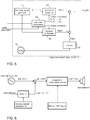
- FIG. 6 illustrates a sound system, which is not part of the claimed invention, that includes, inter alia, engine sound synthesizer 10, audio signal source 1 (e.g., a CD player) and equalizer 2.
- Engine sound synthesizer 10 is supplied with a guide signal (e.g. rpm[n] and/or load[n]) and predefined model parameter database DB, and it is configured to generate the resulting engine sound signal x est [n] by selecting and using a set of model parameters from model parameter database DB in accordance with the current guide signal; the selected set of model parameters are used to synthesize the resulting engine sound signal x est [n]. This may be accomplished as explained in FIG. 5 .
- a guide signal e.g. rpm[n] and/or load[n]
- model parameter database DB predefined model parameter database DB
- the resulting synthetic audio signal x est [n] (which is provided to one or more loudspeakers) will always be the same for a given value of the guide signal(s) and is not affected by the room characteristics of a specific car cabin. That is, synthetic audio signal x est [n] does not depend on the RTF of the listening room in which the audio signal is reproduced. However, the sound reproduction system of FIG. 6 may help to improve the situation.
- Audio signal source 1 provides at least one digital audio signal a[n] (e.g., a set of audio signals in the case of stereo or multi-channel audio), to which synthetic engine sound signal x est [n] is added.
- the at least one resulting sum signal is denoted as y[n].
- audio signal source 1 is optional and audio signal a[n] may also be zero.
- equalizer 2 is essentially a digital filter that operates in accordance with filter transfer function G(e j ⁇ ) (usually a matrix function in the case of more than one audio channel).
- This filter transfer function(s) G(e j ⁇ ) may be designed such that it compensates for the effect of an RTF H(e j ⁇ ), which is associated with a respective RIR h[n] of the car cabin (listening room) in which the sound is reproduced.
- equalizer 2 is configured to equalize room transfer function H(e j ⁇ ).
- the filter transfer function(s) G(e j ⁇ ) may be designed to provide any desired frequency response in order to tune the resulting sound output in a desired manner.
- a brief outline is given below about how an RIR may be obtained for a specific listening room and how the corresponding equalization filter coefficients (also referred to as filter impulse response) may be designed such that the equalization filter compensates for the effect of the listening room.
- RIR H(e j ⁇ ) can generally be measured or estimated using various known system identification techniques. For example, a test signal can be reproduced through a loudspeaker or a group of loudspeakers, while the resulting acoustic signal that arrives at the desired listening position within the listening room is measured by a microphone. RTF H(e j ⁇ ) may then be obtained by filtering the test signal with an adaptive (FIR) filter and iteratively adapting the filter coefficients such that the filtered test signal matches the microphone signal. When the filter coefficients have converged, the filter impulse response (i.e., the filter coefficients in the case of an FIR filter) of the adaptive filter matches the sought RIR h[n].
- FIR adaptive
- the corresponding RTF H(e j ⁇ ) can be obtained by transforming the time-domain RIR h[n] into the frequency domain.
- the actual equalization filter transfer function G(e j ⁇ ) may then be obtained by inversion of RTF H(e j ⁇ ).
- Such inversion may be a challenging task.
- various suitable methods are known in the field and are thus not discussed further here.
- an individual RIR can be obtained for each pair of a loudspeaker and a listening position within the considered listening room. For example, when considering four loudspeakers and four listening positions, 16 RIRs may be obtained. These 16 RIRs may be arranged in a room impulse response matrix, which can be converted to a corresponding transfer matrix in the frequency domain.
- the RTF generally has a matrix form in the case of more than one audio channel. Consequently, the filter transfer function characterizing the equalizer also has a matrix form. In a practical case, in which one digital filter is applied to each audio channel, the transfer matrix can be regarded as diagonal matrix.
- the filter transfer function(s) G(e j ⁇ ) may be pre-determined for a any specific listening room and programmed into a non-volatile memory of the digital signal processing unit, which executes the digital filtering .
- the RIRs of a listening room may be dynamically updated (using measurements) and updated filter coefficients for the filter(s) G(e j ⁇ ) may be obtained based on the current RIRs.
- the equalizing filter(s) are not necessarily directly controlled by the RIRs.
- Various different methods are known for calculating equalization filter coefficients from measured RIRs, for example in the publication US 8,160,282 B2 .
- equalizer 2 receives synthetic engine sound signal x est [n] (optionally superposed with at least one audio signal a[n]) and equalizer 2, which compensates for the effect of RIR h[n] (a matrix in the case of more than one channel) of the listening room. That is, equalizer 2 has filter transfer function G(e j ⁇ ) (representing a set of equalizing filter parameters), which includes at least the (approximate) inverse of RTF H -1 (e j ⁇ ). As mentioned, transfer functions G(e j ⁇ ) and H -1 (e j ⁇ ) are both matrices in the case of more than one channel (multi-channel).
- filter transfer function G(e j ⁇ ) i.e. the equalizing filter parameter set
- filter transfer function G(e j ⁇ ) i.e. the equalizing filter parameter set
- G(e j ⁇ ) the equalizing filter parameter set
- microphones are needed in close proximity to the listening position(s) within the listening room.
- suitable microphones are often installed in premium cars equipped with an active noise cancellation (ANC) system.
- ANC active noise cancellation
- a matrix of RIRs replaces the scalar RIR in the case of multiple audio channels and/or listening positions. Consequently, the transfer behavior of the equalizer is characterized by a matrix of transfer functions (transfer matrix) instead of a scalar transfer function.
- transfer matrix transfer function instead of a scalar transfer function.
- the single-channel case is illustrated in the figures, however, to show the principle and avoid complicated illustrations.
- equalizer 2 of the on-board audio system is used to equalize both audio signal a[n] and synthetic engine sound signal x est [n].
- signals a[n] and x est [n] are superposed (added) and sum signal y[n] is supplied to equalizer 2, which is disposed downstream of engine sound synthesizer 10.
- the solution according to the present invention illustrated in the embodiment of FIG. 7 uses a different approach, according to which the synthetic engine sound signal (denoted as x est '[n] in the present example) is superposed with an already equalized audio signal a'[n], yielding (equalized) sum signal y'[n]. That is, in the embodiment of FIG.
- equalizer 2 is disposed in a signal path parallel to the signal path of synthetic engine sound signal x est '[n]; consequently, equalizer 2 is not needed to equalize synthetic engine sound signal x est '[n], but rather only to equalize (optional) audio signal a[n].
- predefined model parameter database DB is modified in accordance with an equalizing filter parameter set, which depends on RIR h[n] of the listening room (car cabin) or, in the case of more than one channel, in accordance with the matrix of RIRs.
- model parameters in predefined model parameter database DB are modified such that the resulting modified model parameter database DB' contains model parameters that yield (at the output of ESS 10) synthetic engine sound signal x est [n] (for each audio channel), which is already equalized in accordance with RIR h[n].
- the incorporation of the equalization into the model parameters may be achieved, for example, by a simple multiplication of the corresponding amplitude values A 0 , A 1 , A 2 , ..., A N and phase values ⁇ 0 , ⁇ 1 , ⁇ 2 , ..., ⁇ N (associated with fundamental frequency fo and higher harmonics f 1 , f 2 , ..., f N ) with the corresponding transfer function G(e j ⁇ ) of the equalization filter (which is approximately H -1 (e j ⁇ )). In the case of more than one channel, this is done for each audio channel.
- One aspect relates to a method for analyzing sound, particularly engine sound signals picked up near a combustion engine.
- the method includes determining a fundamental frequency of an input signal to be analyzed, thereby making use of the input signal or at least one guide signal. Furthermore, the frequencies of the higher harmonics corresponding to the fundamental frequency are determined, thus resulting in harmonic model parameters.
- the method further includes synthesizing a harmonic signal based on the harmonic model parameters and subtracting the harmonic signal from the input signal to obtain a residual signal. Finally, residual model parameters are estimated based on the residual signal.
- the input signal may be transformed into the frequency domain, thus providing a frequency domain input signal, before being processed further.
- the amount of higher harmonics that can be considered is only limited to the length of the input vectors used, e.g., by the FFT (fast Fourier transform) algorithm that provides the transformation into the frequency domain.
- the processing of the input signal may generally be fully performed in the frequency domain; thus the harmonic signal and the residual signal may also be calculated in the frequency domain.
- the fundamental frequency and the frequencies of the higher harmonics may be derived from at least one guide signal in order to avoid an estimation of the fundamental frequency (and of the frequencies of the higher harmonics) directly from the input signal, which is typically computationally complex.
- the harmonic model parameters may include a frequency vector of the fundamental frequency and the frequencies of the higher harmonics, a corresponding amplitude vector and a corresponding phase vector. Determining the harmonic model parameters may include estimating phase and amplitude values associated with the fundamental frequency and the frequencies of the higher harmonics. Determining the harmonic model parameters may generally include fine-tuning of the fundamental frequency and the frequencies of the higher harmonics obtained from at least one guide signal. Such fine-tuning may entail an iterative modification of the frequencies of the higher harmonics and their corresponding (estimated) amplitude and phase values such that a norm of the residual signal (e.g., an L 2 norm) is minimized. This fine-tuning can be regarded as a kind of optimization process.
- a norm of the residual signal e.g., an L 2 norm
- the residual signal may be filtered with a non-linear filter to smooth the residual signal before estimating the residual model parameters.
- Determining the residual model parameters may include calculating the power spectrum of the residual signal.
- the power spectral density may be calculated for different frequency bands in accordance with a psycho-acoustically motivated frequency scale so as to consider psycho-acoustically critical band limits.
- Another aspect relates to a method for synthesizing a sound signal based on harmonic model parameters and residual model parameters, wherein the parameters may particularly be determined in accordance with the method summarized above.
- the method includes the calculation of the fundamental frequency and frequencies of a number of higher harmonics based on at least one guide signal.
- the residual model parameters and the harmonic model parameters that are associated with the calculated frequencies are provided, and a harmonic signal is synthesized using the harmonic model parameters for the calculated fundamental frequency and frequencies of the higher harmonics.
- a residual signal is synthesized using the residual model parameters.
- the total sound signal may be calculated by superposing the synthesized harmonic signal and the residual signal.
- Pre-filtered white noise may be added to the total sound signal.
- the pre-filtering may include the mapping of the white noise amplitude values into the 0-2 ⁇ phase range, thus generating a phase signal to be added to the total sound signal.
- Synthesizing the residual signal may generally include the generation of a noise signal that has a power spectral density that corresponds to a power spectral density represented by the residual model parameters.
- Another aspect relates to a system for reproducing synthetic engine sound in at least one listening position of a listening room.
- Each listening position is associated with a room transfer function (RTF).
- RTF room transfer function
- One exemplary system includes model parameter database DB, which contains various predefined sets of model parameters.
- the system further includes engine sound synthesizer 10 (see FIG. 6 ), which receives at least one guide signal, wherein those guide signals can be regarded as one vectorial guide signal in the case of more than one guide signal.
- the guide signal(s) may represent the rotational speed of the engine, the engine load, the throttle position or similar measures that may have an impact on the sound of a combustion engine.
- Engine sound synthesizer 10 is configured to select one set of model parameters in accordance with the guide signal(s) and to generate synthetic engine sound signal x est [n] or x est '[n] (see FIGS. 6 and 7 ) in accordance with the selected set of model parameters. At least one loudspeaker 5 is employed to reproduce synthetic engine sound signal x est [n] or x est '[n] by generating a corresponding acoustic engine sound signal.
- the system further includes either equalizer 2 or a model parameter tuning unit.
- the equalizer receives synthetic engine sound signal x est [n] and filters it in accordance with filter transfer function G(e j ⁇ ), which is set such that the effect of the listening room (characterized by the RTF) on the resulting acoustic engine sound signal is approximately compensated at the listening position(s).
- the model parameter tuning unit modifies the predefined sets of model parameters in model parameter database DB in accordance with the equalizing filter parameter set such that the resulting acoustic engine sound signal is approximately compensated at the listening position(s).
- the synthetic engine sound signal is generated from a modified set of model parameters.
- Each set of model parameters represents at least fundamental frequency f 0 and higher harmonic frequencies f 1 , f 2 , ..., f N of a desired engine sound and the corresponding amplitude values A 0 , A 1 , A 2 , ..., A N and phase values ⁇ 0 , ⁇ 1 , ⁇ 2 , ..., ⁇ N .
- a system identification unit may be provided that regularly or continuously measures and updates the RTF used by the equalizer or the model parameter tuning unit.
- FIGS. 8 and 9 illustrate generalizations of the examples of FIGS. 6 and 7 , respectively, for the case of multiple audio channels and loudspeakers.
- the examples of FIGS. 8 and 9 are identical to the previous examples of FIGS. 6 and 7 .
Landscapes
- Physics & Mathematics (AREA)
- Engineering & Computer Science (AREA)
- Acoustics & Sound (AREA)
- Multimedia (AREA)
- Health & Medical Sciences (AREA)
- Audiology, Speech & Language Pathology (AREA)
- General Health & Medical Sciences (AREA)
- Fittings On The Vehicle Exterior For Carrying Loads, And Devices For Holding Or Mounting Articles (AREA)
- Soundproofing, Sound Blocking, And Sound Damping (AREA)
Claims (12)
- System zum Reproduzieren von synthetischem Motorton in mindestens einer Hörposition eines Hörraums unter Verwendung mindestens eines Lautsprechers (5); wobei das System Folgendes umfasst:eine Modellparameterdatenbank (DB), die verschiedene vordefinierte Sätze von Modellparametern beinhaltet;einen Motortongenerator (10), der mindestens ein Führungssignal empfängt, wobei der Motortongenerator (10) dazu ausgelegt ist, einen Satz von Modellparametern gemäß dem mindestens einen Führungssignal auszuwählen und ein synthetisches Motortonsignal (xest[n]) gemäß dem ausgewählten Satz von Modellparametern zu erzeugen;den mindestens einen Lautsprecher (5) zum Reproduzieren des synthetischen Motortons durch Erzeugen eines entsprechenden akustischen Signals; unddadurch gekennzeichnet, dass das System ferner Folgendes umfasst:
eine Modellparametereinstelleinheit, die dazu ausgelegt ist, die vordefinierten Sätze von Modellparametern in der Modellparameterdatenbank (DB) gemäß einem Entzerrfilterparametersatz derart zu modifizieren, dass, wenn das resultierende synthetische Motortonsignal aus einem modifizierten Satz von Modellparametern erzeugt wird, die Wirkung des Hörraums auf das resultierende akustische Signal an der mindestens einen Hörposition kompensiert wird. - System nach Anspruch 1, wobei jeder Satz von Modellparametern mindestens eine Grundfrequenz und höhere Oberschwingungsfrequenzen eines gewünschten Motortons und die entsprechenden Amplituden- und Phasenwerte darstellt.
- System nach Anspruch 1 oder 2, wobei jedes Paar aus Hörposition und Lautsprecher einer Raumübertragungsfunktion (room transfer function - RTF) zugeordnet ist; wobei das System ferner eine Systemidentifikationseinheit beinhaltet, die dazu ausgelegt ist, die von dem Entzerrer oder der Modellparametereinstelleinheit verwendeten Raumübertragungsfunktionen regelmäßig oder kontinuierlich zu messen und zu aktualisieren.
- System nach einem der Ansprüche 1 bis 3, wobei das mindestens eine Führungssignal mindestens eines der Folgenden beinhaltet: ein Drehzahlsignal eines Motors, ein Signal, das die Motorlast darstellt, ein Signal, das ein Fahrzeuggeschwindigkeit darstellt.
- System nach einem der Ansprüche 1 bis 4, ferner umfassend eine Audiosignalquelle, die mindestens ein Audiosignal breitstellt.
- System nach Anspruch 5, wobei das mindestens eine Audiosignal mit dem synthetischen Motortonsignal überlagert wird und das resultierende Summensignal dem Entzerrer zugeführt wird.
- System nach Anspruch 5, wobei die Modellparametereinstelleinheit dazu ausgelegt ist, die vordefinierten Sätze von Modellparametern in der Modellparameterdatenbank gemäß dem Entzerrfilterparametersatz derart zu modifizieren, dass wenn das resultierende synthetische Motortonsignal aus einem modifizierten Satz von Modellparametern erzeugt wird, das resultierende akustische Signal an der mindestens einen Hörposition kompensiert wird, sodass die Wirkung des Hörraums etwa eliminiert wird; und
wobei das synthetische Motortonsignal mit dem Audiosignal überlagert wird, bevor es entsprechenden Lautsprechern zugeführt wird. - System nach Anspruch 7, wobei das mindestens eine Audiosignal entzerrt wird, bevor es auf das synthetische Motortonsignal überlagert wird.
- Verfahren zum Reproduzieren von synthetischem Motorton in mindestens eine Hörposition eines Hörraums unter Verwendung mindestens eines Lautsprechers; wobei das Verfahren Folgendes umfasst:Bereitstellen einer Modellparameterdatenbank, die verschiedene vordefinierte Sätze von Modellparametern beinhaltet;Empfangen mindestens eines Führungssignals und Auswählen eines Satzes von Modellparametern gemäß dem mindestens einen Führungssignal;Generieren mindestens eines synthetischen Motortonsignals gemäß dem ausgewählten Satz von Modellparametern;Reproduzieren des mindestens einen synthetischen Motortonsignals durch Erzeugen mindestens eines entsprechenden akustischen Motortonsignals; unddadurch gekennzeichnet ist, dass das Verfahren ferner Folgendes umfasst:
Modifizieren der vordefinierten Sätze von Modellparametern in der Modellparameterdatenbank gemäß einem Satz von Entzerrfilterparametern, sodass, wenn das resultierende synthetische Motortonsignal aus einem modifizierten Satz von Modellparametern erzeugt wird, die Wirkung des Hörraums auf das resultierende akustische Motortonsignal an der mindestens einen Hörposition kompensiert wird. - Verfahren nach Anspruch 9, wobei jeder Satz von Modellparametern mindestens eine Grundfrequenz und höhere Oberschwingungsfrequenzen eines gewünschten Motortons und die entsprechenden Amplituden- und Phasenwerte darstellt.
- Verfahren nach einem der Ansprüche 9 oder 10, ferner umfassend:
regelmäßiges oder kontinuierliches Messen und Aktualisieren der RTFs, die zum Modifizieren der vordefinierten Sätze von Modellparametern in der Modellparameterdatenbank verwendet werden. - Verfahren nach einem der Ansprüche 9 bis 11, wobei das mindestens eine Führungssignal mindestens eines der Folgenden beinhalte: ein Drehzahlsignal eines Motors, ein Signal, das die Motorlast darstellt, ein Signal, dass eine Fahrzeuggeschwindigkeit darstellt.
Priority Applications (4)
| Application Number | Priority Date | Filing Date | Title |
|---|---|---|---|
| EP13197399.2A EP2884489B1 (de) | 2013-12-16 | 2013-12-16 | Tonsystem mit Motortongenerator |
| JP2014251874A JP6557465B2 (ja) | 2013-12-16 | 2014-12-12 | エンジン音合成装置を含む音声システム |
| US14/572,221 US9536510B2 (en) | 2013-12-16 | 2014-12-16 | Sound system including an engine sound synthesizer |
| CN201410784288.6A CN104715750B (zh) | 2013-12-16 | 2014-12-16 | 包括引擎声音合成器的声音系统 |
Applications Claiming Priority (1)
| Application Number | Priority Date | Filing Date | Title |
|---|---|---|---|
| EP13197399.2A EP2884489B1 (de) | 2013-12-16 | 2013-12-16 | Tonsystem mit Motortongenerator |
Publications (2)
| Publication Number | Publication Date |
|---|---|
| EP2884489A1 EP2884489A1 (de) | 2015-06-17 |
| EP2884489B1 true EP2884489B1 (de) | 2020-02-05 |
Family
ID=49880411
Family Applications (1)
| Application Number | Title | Priority Date | Filing Date |
|---|---|---|---|
| EP13197399.2A Active EP2884489B1 (de) | 2013-12-16 | 2013-12-16 | Tonsystem mit Motortongenerator |
Country Status (4)
| Country | Link |
|---|---|
| US (1) | US9536510B2 (de) |
| EP (1) | EP2884489B1 (de) |
| JP (1) | JP6557465B2 (de) |
| CN (1) | CN104715750B (de) |
Families Citing this family (24)
| Publication number | Priority date | Publication date | Assignee | Title |
|---|---|---|---|---|
| US10380991B2 (en) * | 2015-04-13 | 2019-08-13 | Sony Corporation | Signal processing device, signal processing method, and program for selectable spatial correction of multichannel audio signal |
| US10674255B2 (en) | 2015-09-03 | 2020-06-02 | Sony Corporation | Sound processing device, method and program |
| JP6841229B2 (ja) | 2015-12-10 | 2021-03-10 | ソニー株式会社 | 音声処理装置および方法、並びにプログラム |
| DE102016100542A1 (de) * | 2016-01-14 | 2017-07-20 | Faurecia Emissions Control Technologies, Germany Gmbh | Verfahren zur Erzeugung eines Ansteuerungssignals für einen in einem Motorfahrzeug angeordneten Lautsprecher sowie Abgasanlage für einen Motor und Soundsystem für eine Fahrgastzelle |
| US10020788B2 (en) * | 2016-03-02 | 2018-07-10 | Bose Corporation | Vehicle engine sound management |
| US9693139B1 (en) * | 2016-03-30 | 2017-06-27 | Ford Global Tecghnologies, LLC | Systems and methods for electronic sound enhancement tuning |
| JP6465058B2 (ja) * | 2016-03-31 | 2019-02-06 | マツダ株式会社 | 車両用効果音発生装置 |
| JP6281590B2 (ja) * | 2016-03-31 | 2018-02-21 | マツダ株式会社 | 車両用効果音発生装置 |
| US9944127B2 (en) * | 2016-08-12 | 2018-04-17 | 2236008 Ontario Inc. | System and method for synthesizing an engine sound |
| KR101804772B1 (ko) * | 2016-08-25 | 2017-12-05 | 현대자동차주식회사 | 사운드 제어장치, 차량 및 그 제어방법 |
| KR101840205B1 (ko) * | 2016-09-02 | 2018-05-04 | 현대자동차주식회사 | 사운드 제어장치, 차량 및 그 제어방법 |
| US10371079B2 (en) * | 2016-09-09 | 2019-08-06 | Ford Global Technologies, Llc | Method and system for knock sensor rationality check |
| US10679617B2 (en) * | 2017-12-06 | 2020-06-09 | Synaptics Incorporated | Voice enhancement in audio signals through modified generalized eigenvalue beamformer |
| EP3553772A1 (de) * | 2018-04-09 | 2019-10-16 | Harman International Industries, Incorporated | Verfahren und vorrichtung zum steuern von fahrzeuggeräuschen in einem fahrzeug |
| WO2019231452A1 (en) * | 2018-05-31 | 2019-12-05 | Harman International Industries, Incorporated | System and method for steady state vehicle sound synthesis |
| US11351916B2 (en) * | 2018-09-27 | 2022-06-07 | Harman International Industries, Incorporated | Vehicle sound synthesis during engine start conditions |
| CN111031446B (zh) * | 2019-12-24 | 2021-10-08 | 无锡吉兴汽车声学部件科技有限公司 | 一种自动补偿音频通路传递函数的发声系统及方法 |
| US11064294B1 (en) | 2020-01-10 | 2021-07-13 | Synaptics Incorporated | Multiple-source tracking and voice activity detections for planar microphone arrays |
| CN112652315B (zh) * | 2020-08-03 | 2024-08-16 | 昆山杜克大学 | 基于深度学习的汽车引擎声实时合成系统及方法 |
| US11322132B2 (en) | 2020-08-17 | 2022-05-03 | Toyota Motor Engineering & Manufacturing North America, Inc. | Engine sound enhancement |
| CN112466274B (zh) * | 2020-10-29 | 2024-02-27 | 中科上声(苏州)电子有限公司 | 一种电动汽车的车内主动发声方法及系统 |
| US12057138B2 (en) | 2022-01-10 | 2024-08-06 | Synaptics Incorporated | Cascade audio spotting system |
| CN116206624B (zh) * | 2023-05-04 | 2023-08-29 | 科大讯飞(苏州)科技有限公司 | 一种车辆声浪合成方法、装置、存储介质及设备 |
| CN117651238B (zh) * | 2024-01-30 | 2024-05-31 | 科大讯飞(苏州)科技有限公司 | 音频播放方法、音频补偿系数的确定方法和汽车 |
Citations (1)
| Publication number | Priority date | Publication date | Assignee | Title |
|---|---|---|---|---|
| US20110216916A1 (en) * | 2010-03-03 | 2011-09-08 | Hera Cristian M | Vehicle engine sound enhancement |
Family Cites Families (13)
| Publication number | Priority date | Publication date | Assignee | Title |
|---|---|---|---|---|
| US5371802A (en) * | 1989-04-20 | 1994-12-06 | Group Lotus Limited | Sound synthesizer in a vehicle |
| JPH086575A (ja) * | 1994-06-24 | 1996-01-12 | Fujitsu Ten Ltd | 騒音制御装置 |
| DE19945259C1 (de) * | 1999-09-21 | 2001-01-11 | Bayerische Motoren Werke Ag | Vorrichtung zur elektroakustischen Geräuscherzeugung bei einem Kraftfahrzeug |
| US6959094B1 (en) * | 2000-04-20 | 2005-10-25 | Analog Devices, Inc. | Apparatus and methods for synthesis of internal combustion engine vehicle sounds |
| JP4173891B2 (ja) * | 2005-03-22 | 2008-10-29 | 本田技研工業株式会社 | 移動体用効果音発生装置 |
| JP4174062B2 (ja) * | 2006-03-27 | 2008-10-29 | 本田技研工業株式会社 | 車両用効果音発生装置 |
| JP2007264485A (ja) * | 2006-03-29 | 2007-10-11 | Honda Motor Co Ltd | 車両用能動音響制御装置 |
| ATE491314T1 (de) | 2006-04-05 | 2010-12-15 | Harman Becker Automotive Sys | Verfahren zum automatischen entzerren eines beschallungssystems |
| JP4894342B2 (ja) * | 2006-04-20 | 2012-03-14 | パナソニック株式会社 | 音響再生装置 |
| JP4384681B2 (ja) * | 2007-07-25 | 2009-12-16 | 本田技研工業株式会社 | 能動型効果音発生装置 |
| JP4967000B2 (ja) * | 2009-06-30 | 2012-07-04 | 本田技研工業株式会社 | 効果音発生装置 |
| CN102481878A (zh) * | 2009-09-10 | 2012-05-30 | 先锋株式会社 | 噪音降低设备 |
| US10414337B2 (en) | 2013-11-19 | 2019-09-17 | Harman International Industries, Inc. | Apparatus for providing environmental noise compensation for a synthesized vehicle sound |
-
2013
- 2013-12-16 EP EP13197399.2A patent/EP2884489B1/de active Active
-
2014
- 2014-12-12 JP JP2014251874A patent/JP6557465B2/ja active Active
- 2014-12-16 US US14/572,221 patent/US9536510B2/en active Active
- 2014-12-16 CN CN201410784288.6A patent/CN104715750B/zh active Active
Patent Citations (1)
| Publication number | Priority date | Publication date | Assignee | Title |
|---|---|---|---|---|
| US20110216916A1 (en) * | 2010-03-03 | 2011-09-08 | Hera Cristian M | Vehicle engine sound enhancement |
Also Published As
| Publication number | Publication date |
|---|---|
| CN104715750B (zh) | 2019-12-06 |
| JP2015118376A (ja) | 2015-06-25 |
| CN104715750A (zh) | 2015-06-17 |
| US20150170629A1 (en) | 2015-06-18 |
| US9536510B2 (en) | 2017-01-03 |
| JP6557465B2 (ja) | 2019-08-07 |
| EP2884489A1 (de) | 2015-06-17 |
Similar Documents
| Publication | Publication Date | Title |
|---|---|---|
| EP2884489B1 (de) | Tonsystem mit Motortongenerator | |
| EP2685448B1 (de) | Motorenklangsynthese | |
| EP2996112B1 (de) | Adaptives Rauschunterdrückungsystem mit verbesserter Robustheit | |
| EP3437090B1 (de) | Adaptive modellierung eines sekundären pfads in einem system zur aktiven rauschunterdrückung | |
| US7885417B2 (en) | Active noise tuning system | |
| EP2311271B1 (de) | Verfahren zur adaptiven steuerung und entzerrung elektroakustischer kanäle | |
| JP5933747B2 (ja) | 仮想オーディオシステムの調整 | |
| EP2884488A1 (de) | Aktives Geräuschdämpfungssystem | |
| CN104937659B (zh) | 车辆引擎声音提取以及再现 | |
| JP6870078B2 (ja) | 動的サウンド調整のための雑音推定 | |
| JP2008192136A (ja) | 変換器パラメータの最適推定装置および方法 | |
| US20180233124A1 (en) | Noise reduction device, noise reduction method, and program | |
| US20140226828A1 (en) | Method and Arrangement for Auralizing and Assessing Signal Distortion | |
| CN103580630B (zh) | 自动响度控制 | |
| Chen et al. | A computationally efficient feedforward time–frequency-domain hybrid active sound profiling algorithm for vehicle interior noise | |
| US9959852B2 (en) | Vehicle engine sound extraction | |
| US11990112B2 (en) | Apparatus, system and/or method for acoustic road noise peak frequency cancellation | |
| JP2827603B2 (ja) | 能動型騒音制御装置 | |
| Bellini et al. | Car cockpit equalization by warping filters | |
| JP2023114445A (ja) | ロードノイズキャンセレーションシェーピングフィルタ | |
| JP2010197707A (ja) | 音場制御装置 |
Legal Events
| Date | Code | Title | Description |
|---|---|---|---|
| PUAI | Public reference made under article 153(3) epc to a published international application that has entered the european phase |
Free format text: ORIGINAL CODE: 0009012 |
|
| 17P | Request for examination filed |
Effective date: 20131216 |
|
| AK | Designated contracting states |
Kind code of ref document: A1 Designated state(s): AL AT BE BG CH CY CZ DE DK EE ES FI FR GB GR HR HU IE IS IT LI LT LU LV MC MK MT NL NO PL PT RO RS SE SI SK SM TR |
|
| AX | Request for extension of the european patent |
Extension state: BA ME |
|
| R17P | Request for examination filed (corrected) |
Effective date: 20151215 |
|
| RBV | Designated contracting states (corrected) |
Designated state(s): AL AT BE BG CH CY CZ DE DK EE ES FI FR GB GR HR HU IE IS IT LI LT LU LV MC MK MT NL NO PL PT RO RS SE SI SK SM TR |
|
| STAA | Information on the status of an ep patent application or granted ep patent |
Free format text: STATUS: EXAMINATION IS IN PROGRESS |
|
| 17Q | First examination report despatched |
Effective date: 20180222 |
|
| RIC1 | Information provided on ipc code assigned before grant |
Ipc: G10K 15/02 20060101AFI20190821BHEP Ipc: G10H 5/00 20060101ALN20190821BHEP |
|
| GRAP | Despatch of communication of intention to grant a patent |
Free format text: ORIGINAL CODE: EPIDOSNIGR1 |
|
| STAA | Information on the status of an ep patent application or granted ep patent |
Free format text: STATUS: GRANT OF PATENT IS INTENDED |
|
| RIC1 | Information provided on ipc code assigned before grant |
Ipc: G10H 5/00 20060101ALN20190919BHEP Ipc: G10K 15/02 20060101AFI20190919BHEP |
|
| RIC1 | Information provided on ipc code assigned before grant |
Ipc: G10K 15/02 20060101AFI20190925BHEP Ipc: G10H 5/00 20060101ALN20190925BHEP |
|
| INTG | Intention to grant announced |
Effective date: 20191008 |
|
| GRAS | Grant fee paid |
Free format text: ORIGINAL CODE: EPIDOSNIGR3 |
|
| GRAA | (expected) grant |
Free format text: ORIGINAL CODE: 0009210 |
|
| STAA | Information on the status of an ep patent application or granted ep patent |
Free format text: STATUS: THE PATENT HAS BEEN GRANTED |
|
| AK | Designated contracting states |
Kind code of ref document: B1 Designated state(s): AL AT BE BG CH CY CZ DE DK EE ES FI FR GB GR HR HU IE IS IT LI LT LU LV MC MK MT NL NO PL PT RO RS SE SI SK SM TR |
|
| REG | Reference to a national code |
Ref country code: GB Ref legal event code: FG4D |
|
| REG | Reference to a national code |
Ref country code: AT Ref legal event code: REF Ref document number: 1230433 Country of ref document: AT Kind code of ref document: T Effective date: 20200215 |
|
| REG | Reference to a national code |
Ref country code: DE Ref legal event code: R096 Ref document number: 602013065466 Country of ref document: DE |
|
| REG | Reference to a national code |
Ref country code: IE Ref legal event code: FG4D |
|
| REG | Reference to a national code |
Ref country code: CH Ref legal event code: EP |
|
| REG | Reference to a national code |
Ref country code: NL Ref legal event code: MP Effective date: 20200205 |
|
| PG25 | Lapsed in a contracting state [announced via postgrant information from national office to epo] |
Ref country code: PT Free format text: LAPSE BECAUSE OF FAILURE TO SUBMIT A TRANSLATION OF THE DESCRIPTION OR TO PAY THE FEE WITHIN THE PRESCRIBED TIME-LIMIT Effective date: 20200628 Ref country code: RS Free format text: LAPSE BECAUSE OF FAILURE TO SUBMIT A TRANSLATION OF THE DESCRIPTION OR TO PAY THE FEE WITHIN THE PRESCRIBED TIME-LIMIT Effective date: 20200205 Ref country code: NO Free format text: LAPSE BECAUSE OF FAILURE TO SUBMIT A TRANSLATION OF THE DESCRIPTION OR TO PAY THE FEE WITHIN THE PRESCRIBED TIME-LIMIT Effective date: 20200505 Ref country code: FI Free format text: LAPSE BECAUSE OF FAILURE TO SUBMIT A TRANSLATION OF THE DESCRIPTION OR TO PAY THE FEE WITHIN THE PRESCRIBED TIME-LIMIT Effective date: 20200205 |
|
| REG | Reference to a national code |
Ref country code: LT Ref legal event code: MG4D |
|
| PG25 | Lapsed in a contracting state [announced via postgrant information from national office to epo] |
Ref country code: GR Free format text: LAPSE BECAUSE OF FAILURE TO SUBMIT A TRANSLATION OF THE DESCRIPTION OR TO PAY THE FEE WITHIN THE PRESCRIBED TIME-LIMIT Effective date: 20200506 Ref country code: HR Free format text: LAPSE BECAUSE OF FAILURE TO SUBMIT A TRANSLATION OF THE DESCRIPTION OR TO PAY THE FEE WITHIN THE PRESCRIBED TIME-LIMIT Effective date: 20200205 Ref country code: SE Free format text: LAPSE BECAUSE OF FAILURE TO SUBMIT A TRANSLATION OF THE DESCRIPTION OR TO PAY THE FEE WITHIN THE PRESCRIBED TIME-LIMIT Effective date: 20200205 Ref country code: IS Free format text: LAPSE BECAUSE OF FAILURE TO SUBMIT A TRANSLATION OF THE DESCRIPTION OR TO PAY THE FEE WITHIN THE PRESCRIBED TIME-LIMIT Effective date: 20200605 Ref country code: LV Free format text: LAPSE BECAUSE OF FAILURE TO SUBMIT A TRANSLATION OF THE DESCRIPTION OR TO PAY THE FEE WITHIN THE PRESCRIBED TIME-LIMIT Effective date: 20200205 Ref country code: BG Free format text: LAPSE BECAUSE OF FAILURE TO SUBMIT A TRANSLATION OF THE DESCRIPTION OR TO PAY THE FEE WITHIN THE PRESCRIBED TIME-LIMIT Effective date: 20200505 |
|
| PG25 | Lapsed in a contracting state [announced via postgrant information from national office to epo] |
Ref country code: NL Free format text: LAPSE BECAUSE OF FAILURE TO SUBMIT A TRANSLATION OF THE DESCRIPTION OR TO PAY THE FEE WITHIN THE PRESCRIBED TIME-LIMIT Effective date: 20200205 |
|
| PG25 | Lapsed in a contracting state [announced via postgrant information from national office to epo] |
Ref country code: ES Free format text: LAPSE BECAUSE OF FAILURE TO SUBMIT A TRANSLATION OF THE DESCRIPTION OR TO PAY THE FEE WITHIN THE PRESCRIBED TIME-LIMIT Effective date: 20200205 Ref country code: LT Free format text: LAPSE BECAUSE OF FAILURE TO SUBMIT A TRANSLATION OF THE DESCRIPTION OR TO PAY THE FEE WITHIN THE PRESCRIBED TIME-LIMIT Effective date: 20200205 Ref country code: CZ Free format text: LAPSE BECAUSE OF FAILURE TO SUBMIT A TRANSLATION OF THE DESCRIPTION OR TO PAY THE FEE WITHIN THE PRESCRIBED TIME-LIMIT Effective date: 20200205 Ref country code: RO Free format text: LAPSE BECAUSE OF FAILURE TO SUBMIT A TRANSLATION OF THE DESCRIPTION OR TO PAY THE FEE WITHIN THE PRESCRIBED TIME-LIMIT Effective date: 20200205 Ref country code: SM Free format text: LAPSE BECAUSE OF FAILURE TO SUBMIT A TRANSLATION OF THE DESCRIPTION OR TO PAY THE FEE WITHIN THE PRESCRIBED TIME-LIMIT Effective date: 20200205 Ref country code: EE Free format text: LAPSE BECAUSE OF FAILURE TO SUBMIT A TRANSLATION OF THE DESCRIPTION OR TO PAY THE FEE WITHIN THE PRESCRIBED TIME-LIMIT Effective date: 20200205 Ref country code: DK Free format text: LAPSE BECAUSE OF FAILURE TO SUBMIT A TRANSLATION OF THE DESCRIPTION OR TO PAY THE FEE WITHIN THE PRESCRIBED TIME-LIMIT Effective date: 20200205 Ref country code: SK Free format text: LAPSE BECAUSE OF FAILURE TO SUBMIT A TRANSLATION OF THE DESCRIPTION OR TO PAY THE FEE WITHIN THE PRESCRIBED TIME-LIMIT Effective date: 20200205 |
|
| REG | Reference to a national code |
Ref country code: DE Ref legal event code: R097 Ref document number: 602013065466 Country of ref document: DE |
|
| REG | Reference to a national code |
Ref country code: AT Ref legal event code: MK05 Ref document number: 1230433 Country of ref document: AT Kind code of ref document: T Effective date: 20200205 |
|
| PLBE | No opposition filed within time limit |
Free format text: ORIGINAL CODE: 0009261 |
|
| STAA | Information on the status of an ep patent application or granted ep patent |
Free format text: STATUS: NO OPPOSITION FILED WITHIN TIME LIMIT |
|
| 26N | No opposition filed |
Effective date: 20201106 |
|
| PG25 | Lapsed in a contracting state [announced via postgrant information from national office to epo] |
Ref country code: AT Free format text: LAPSE BECAUSE OF FAILURE TO SUBMIT A TRANSLATION OF THE DESCRIPTION OR TO PAY THE FEE WITHIN THE PRESCRIBED TIME-LIMIT Effective date: 20200205 Ref country code: IT Free format text: LAPSE BECAUSE OF FAILURE TO SUBMIT A TRANSLATION OF THE DESCRIPTION OR TO PAY THE FEE WITHIN THE PRESCRIBED TIME-LIMIT Effective date: 20200205 |
|
| PG25 | Lapsed in a contracting state [announced via postgrant information from national office to epo] |
Ref country code: SI Free format text: LAPSE BECAUSE OF FAILURE TO SUBMIT A TRANSLATION OF THE DESCRIPTION OR TO PAY THE FEE WITHIN THE PRESCRIBED TIME-LIMIT Effective date: 20200205 Ref country code: PL Free format text: LAPSE BECAUSE OF FAILURE TO SUBMIT A TRANSLATION OF THE DESCRIPTION OR TO PAY THE FEE WITHIN THE PRESCRIBED TIME-LIMIT Effective date: 20200205 |
|
| REG | Reference to a national code |
Ref country code: CH Ref legal event code: PL |
|
| PG25 | Lapsed in a contracting state [announced via postgrant information from national office to epo] |
Ref country code: MC Free format text: LAPSE BECAUSE OF FAILURE TO SUBMIT A TRANSLATION OF THE DESCRIPTION OR TO PAY THE FEE WITHIN THE PRESCRIBED TIME-LIMIT Effective date: 20200205 |
|
| REG | Reference to a national code |
Ref country code: BE Ref legal event code: MM Effective date: 20201231 |
|
| PG25 | Lapsed in a contracting state [announced via postgrant information from national office to epo] |
Ref country code: IE Free format text: LAPSE BECAUSE OF NON-PAYMENT OF DUE FEES Effective date: 20201216 Ref country code: LU Free format text: LAPSE BECAUSE OF NON-PAYMENT OF DUE FEES Effective date: 20201216 Ref country code: FR Free format text: LAPSE BECAUSE OF NON-PAYMENT OF DUE FEES Effective date: 20201231 |
|
| PG25 | Lapsed in a contracting state [announced via postgrant information from national office to epo] |
Ref country code: LI Free format text: LAPSE BECAUSE OF NON-PAYMENT OF DUE FEES Effective date: 20201231 Ref country code: CH Free format text: LAPSE BECAUSE OF NON-PAYMENT OF DUE FEES Effective date: 20201231 |
|
| PG25 | Lapsed in a contracting state [announced via postgrant information from national office to epo] |
Ref country code: TR Free format text: LAPSE BECAUSE OF FAILURE TO SUBMIT A TRANSLATION OF THE DESCRIPTION OR TO PAY THE FEE WITHIN THE PRESCRIBED TIME-LIMIT Effective date: 20200205 Ref country code: MT Free format text: LAPSE BECAUSE OF FAILURE TO SUBMIT A TRANSLATION OF THE DESCRIPTION OR TO PAY THE FEE WITHIN THE PRESCRIBED TIME-LIMIT Effective date: 20200205 Ref country code: CY Free format text: LAPSE BECAUSE OF FAILURE TO SUBMIT A TRANSLATION OF THE DESCRIPTION OR TO PAY THE FEE WITHIN THE PRESCRIBED TIME-LIMIT Effective date: 20200205 |
|
| PG25 | Lapsed in a contracting state [announced via postgrant information from national office to epo] |
Ref country code: MK Free format text: LAPSE BECAUSE OF FAILURE TO SUBMIT A TRANSLATION OF THE DESCRIPTION OR TO PAY THE FEE WITHIN THE PRESCRIBED TIME-LIMIT Effective date: 20200205 Ref country code: AL Free format text: LAPSE BECAUSE OF FAILURE TO SUBMIT A TRANSLATION OF THE DESCRIPTION OR TO PAY THE FEE WITHIN THE PRESCRIBED TIME-LIMIT Effective date: 20200205 |
|
| PG25 | Lapsed in a contracting state [announced via postgrant information from national office to epo] |
Ref country code: BE Free format text: LAPSE BECAUSE OF NON-PAYMENT OF DUE FEES Effective date: 20201231 |
|
| P01 | Opt-out of the competence of the unified patent court (upc) registered |
Effective date: 20230526 |
|
| PGFP | Annual fee paid to national office [announced via postgrant information from national office to epo] |
Ref country code: DE Payment date: 20241121 Year of fee payment: 12 |
|
| PGFP | Annual fee paid to national office [announced via postgrant information from national office to epo] |
Ref country code: GB Payment date: 20241122 Year of fee payment: 12 |