EP2792326B1 - Multi-button electrosurgical apparatus - Google Patents
Multi-button electrosurgical apparatus Download PDFInfo
- Publication number
- EP2792326B1 EP2792326B1 EP13005083.4A EP13005083A EP2792326B1 EP 2792326 B1 EP2792326 B1 EP 2792326B1 EP 13005083 A EP13005083 A EP 13005083A EP 2792326 B1 EP2792326 B1 EP 2792326B1
- Authority
- EP
- European Patent Office
- Prior art keywords
- electrosurgical
- activation
- electrosurgical apparatus
- power
- coupled
- Prior art date
- Legal status (The legal status is an assumption and is not a legal conclusion. Google has not performed a legal analysis and makes no representation as to the accuracy of the status listed.)
- Active
Links
- 230000004913 activation Effects 0.000 claims description 84
- 239000003990 capacitor Substances 0.000 claims description 25
- 230000000875 corresponding effect Effects 0.000 claims description 8
- 238000001994 activation Methods 0.000 description 73
- 230000015271 coagulation Effects 0.000 description 21
- 238000005345 coagulation Methods 0.000 description 21
- 239000004020 conductor Substances 0.000 description 17
- 238000000034 method Methods 0.000 description 16
- 210000001519 tissue Anatomy 0.000 description 13
- 238000002955 isolation Methods 0.000 description 11
- 230000008859 change Effects 0.000 description 10
- 238000010586 diagram Methods 0.000 description 8
- 210000002381 plasma Anatomy 0.000 description 8
- 230000006870 function Effects 0.000 description 7
- 238000001356 surgical procedure Methods 0.000 description 6
- 230000000694 effects Effects 0.000 description 4
- 230000008569 process Effects 0.000 description 4
- 230000000007 visual effect Effects 0.000 description 4
- 230000009471 action Effects 0.000 description 3
- 238000003825 pressing Methods 0.000 description 3
- 238000001228 spectrum Methods 0.000 description 3
- 230000004888 barrier function Effects 0.000 description 2
- 230000008901 benefit Effects 0.000 description 2
- 238000010891 electric arc Methods 0.000 description 2
- 238000005259 measurement Methods 0.000 description 2
- 230000001105 regulatory effect Effects 0.000 description 2
- 206010028980 Neoplasm Diseases 0.000 description 1
- 238000002679 ablation Methods 0.000 description 1
- 239000012080 ambient air Substances 0.000 description 1
- 210000004369 blood Anatomy 0.000 description 1
- 239000008280 blood Substances 0.000 description 1
- 210000001124 body fluid Anatomy 0.000 description 1
- 239000000919 ceramic Substances 0.000 description 1
- 230000005495 cold plasma Effects 0.000 description 1
- 238000010276 construction Methods 0.000 description 1
- 230000001276 controlling effect Effects 0.000 description 1
- 230000002596 correlated effect Effects 0.000 description 1
- 230000008878 coupling Effects 0.000 description 1
- 238000010168 coupling process Methods 0.000 description 1
- 238000005859 coupling reaction Methods 0.000 description 1
- 239000013078 crystal Substances 0.000 description 1
- 230000001419 dependent effect Effects 0.000 description 1
- 238000001914 filtration Methods 0.000 description 1
- 230000023597 hemostasis Effects 0.000 description 1
- 230000003993 interaction Effects 0.000 description 1
- 230000002452 interceptive effect Effects 0.000 description 1
- 230000001473 noxious effect Effects 0.000 description 1
- 230000037361 pathway Effects 0.000 description 1
- 239000000779 smoke Substances 0.000 description 1
- 230000001954 sterilising effect Effects 0.000 description 1
- 238000004659 sterilization and disinfection Methods 0.000 description 1
- 230000007704 transition Effects 0.000 description 1
Images


Classifications
-
- A—HUMAN NECESSITIES
- A61—MEDICAL OR VETERINARY SCIENCE; HYGIENE
- A61B—DIAGNOSIS; SURGERY; IDENTIFICATION
- A61B18/00—Surgical instruments, devices or methods for transferring non-mechanical forms of energy to or from the body
- A61B18/04—Surgical instruments, devices or methods for transferring non-mechanical forms of energy to or from the body by heating
- A61B18/12—Surgical instruments, devices or methods for transferring non-mechanical forms of energy to or from the body by heating by passing a current through the tissue to be heated, e.g. high-frequency current
- A61B18/14—Probes or electrodes therefor
-
- A—HUMAN NECESSITIES
- A61—MEDICAL OR VETERINARY SCIENCE; HYGIENE
- A61B—DIAGNOSIS; SURGERY; IDENTIFICATION
- A61B18/00—Surgical instruments, devices or methods for transferring non-mechanical forms of energy to or from the body
- A61B18/04—Surgical instruments, devices or methods for transferring non-mechanical forms of energy to or from the body by heating
- A61B18/042—Surgical instruments, devices or methods for transferring non-mechanical forms of energy to or from the body by heating using additional gas becoming plasma
-
- A—HUMAN NECESSITIES
- A61—MEDICAL OR VETERINARY SCIENCE; HYGIENE
- A61B—DIAGNOSIS; SURGERY; IDENTIFICATION
- A61B18/00—Surgical instruments, devices or methods for transferring non-mechanical forms of energy to or from the body
- A61B18/04—Surgical instruments, devices or methods for transferring non-mechanical forms of energy to or from the body by heating
- A61B18/12—Surgical instruments, devices or methods for transferring non-mechanical forms of energy to or from the body by heating by passing a current through the tissue to be heated, e.g. high-frequency current
- A61B18/14—Probes or electrodes therefor
- A61B18/1402—Probes for open surgery
-
- A—HUMAN NECESSITIES
- A61—MEDICAL OR VETERINARY SCIENCE; HYGIENE
- A61B—DIAGNOSIS; SURGERY; IDENTIFICATION
- A61B17/00—Surgical instruments, devices or methods
- A61B17/32—Surgical cutting instruments
- A61B17/3209—Incision instruments
-
- A—HUMAN NECESSITIES
- A61—MEDICAL OR VETERINARY SCIENCE; HYGIENE
- A61B—DIAGNOSIS; SURGERY; IDENTIFICATION
- A61B18/00—Surgical instruments, devices or methods for transferring non-mechanical forms of energy to or from the body
- A61B18/04—Surgical instruments, devices or methods for transferring non-mechanical forms of energy to or from the body by heating
- A61B18/12—Surgical instruments, devices or methods for transferring non-mechanical forms of energy to or from the body by heating by passing a current through the tissue to be heated, e.g. high-frequency current
- A61B18/1206—Generators therefor
-
- A—HUMAN NECESSITIES
- A61—MEDICAL OR VETERINARY SCIENCE; HYGIENE
- A61B—DIAGNOSIS; SURGERY; IDENTIFICATION
- A61B18/00—Surgical instruments, devices or methods for transferring non-mechanical forms of energy to or from the body
- A61B2018/00053—Mechanical features of the instrument of device
- A61B2018/00172—Connectors and adapters therefor
- A61B2018/00178—Electrical connectors
-
- A—HUMAN NECESSITIES
- A61—MEDICAL OR VETERINARY SCIENCE; HYGIENE
- A61B—DIAGNOSIS; SURGERY; IDENTIFICATION
- A61B18/00—Surgical instruments, devices or methods for transferring non-mechanical forms of energy to or from the body
- A61B2018/00571—Surgical instruments, devices or methods for transferring non-mechanical forms of energy to or from the body for achieving a particular surgical effect
- A61B2018/00589—Coagulation
-
- A—HUMAN NECESSITIES
- A61—MEDICAL OR VETERINARY SCIENCE; HYGIENE
- A61B—DIAGNOSIS; SURGERY; IDENTIFICATION
- A61B18/00—Surgical instruments, devices or methods for transferring non-mechanical forms of energy to or from the body
- A61B2018/00571—Surgical instruments, devices or methods for transferring non-mechanical forms of energy to or from the body for achieving a particular surgical effect
- A61B2018/00607—Coagulation and cutting with the same instrument
-
- A—HUMAN NECESSITIES
- A61—MEDICAL OR VETERINARY SCIENCE; HYGIENE
- A61B—DIAGNOSIS; SURGERY; IDENTIFICATION
- A61B18/00—Surgical instruments, devices or methods for transferring non-mechanical forms of energy to or from the body
- A61B2018/0091—Handpieces of the surgical instrument or device
-
- A—HUMAN NECESSITIES
- A61—MEDICAL OR VETERINARY SCIENCE; HYGIENE
- A61B—DIAGNOSIS; SURGERY; IDENTIFICATION
- A61B18/00—Surgical instruments, devices or methods for transferring non-mechanical forms of energy to or from the body
- A61B2018/0091—Handpieces of the surgical instrument or device
- A61B2018/00916—Handpieces of the surgical instrument or device with means for switching or controlling the main function of the instrument or device
- A61B2018/00922—Handpieces of the surgical instrument or device with means for switching or controlling the main function of the instrument or device by switching or controlling the treatment energy directly within the hand-piece
-
- A—HUMAN NECESSITIES
- A61—MEDICAL OR VETERINARY SCIENCE; HYGIENE
- A61B—DIAGNOSIS; SURGERY; IDENTIFICATION
- A61B18/00—Surgical instruments, devices or methods for transferring non-mechanical forms of energy to or from the body
- A61B2018/0091—Handpieces of the surgical instrument or device
- A61B2018/00916—Handpieces of the surgical instrument or device with means for switching or controlling the main function of the instrument or device
- A61B2018/00928—Handpieces of the surgical instrument or device with means for switching or controlling the main function of the instrument or device by sending a signal to an external energy source
-
- A—HUMAN NECESSITIES
- A61—MEDICAL OR VETERINARY SCIENCE; HYGIENE
- A61B—DIAGNOSIS; SURGERY; IDENTIFICATION
- A61B18/00—Surgical instruments, devices or methods for transferring non-mechanical forms of energy to or from the body
- A61B2018/0091—Handpieces of the surgical instrument or device
- A61B2018/00916—Handpieces of the surgical instrument or device with means for switching or controlling the main function of the instrument or device
- A61B2018/0094—Types of switches or controllers
-
- A—HUMAN NECESSITIES
- A61—MEDICAL OR VETERINARY SCIENCE; HYGIENE
- A61B—DIAGNOSIS; SURGERY; IDENTIFICATION
- A61B18/00—Surgical instruments, devices or methods for transferring non-mechanical forms of energy to or from the body
- A61B2018/0091—Handpieces of the surgical instrument or device
- A61B2018/00916—Handpieces of the surgical instrument or device with means for switching or controlling the main function of the instrument or device
- A61B2018/00958—Handpieces of the surgical instrument or device with means for switching or controlling the main function of the instrument or device for switching between different working modes of the main function
-
- A—HUMAN NECESSITIES
- A61—MEDICAL OR VETERINARY SCIENCE; HYGIENE
- A61B—DIAGNOSIS; SURGERY; IDENTIFICATION
- A61B18/00—Surgical instruments, devices or methods for transferring non-mechanical forms of energy to or from the body
- A61B2018/00988—Means for storing information, e.g. calibration constants, or for preventing excessive use, e.g. usage, service life counter
-
- A—HUMAN NECESSITIES
- A61—MEDICAL OR VETERINARY SCIENCE; HYGIENE
- A61B—DIAGNOSIS; SURGERY; IDENTIFICATION
- A61B18/00—Surgical instruments, devices or methods for transferring non-mechanical forms of energy to or from the body
- A61B18/04—Surgical instruments, devices or methods for transferring non-mechanical forms of energy to or from the body by heating
- A61B18/12—Surgical instruments, devices or methods for transferring non-mechanical forms of energy to or from the body by heating by passing a current through the tissue to be heated, e.g. high-frequency current
- A61B18/1206—Generators therefor
- A61B2018/128—Generators therefor generating two or more frequencies
-
- A—HUMAN NECESSITIES
- A61—MEDICAL OR VETERINARY SCIENCE; HYGIENE
- A61B—DIAGNOSIS; SURGERY; IDENTIFICATION
- A61B18/00—Surgical instruments, devices or methods for transferring non-mechanical forms of energy to or from the body
- A61B18/04—Surgical instruments, devices or methods for transferring non-mechanical forms of energy to or from the body by heating
- A61B18/12—Surgical instruments, devices or methods for transferring non-mechanical forms of energy to or from the body by heating by passing a current through the tissue to be heated, e.g. high-frequency current
- A61B18/1206—Generators therefor
- A61B2018/1286—Generators therefor having a specific transformer
-
- A—HUMAN NECESSITIES
- A61—MEDICAL OR VETERINARY SCIENCE; HYGIENE
- A61B—DIAGNOSIS; SURGERY; IDENTIFICATION
- A61B18/00—Surgical instruments, devices or methods for transferring non-mechanical forms of energy to or from the body
- A61B18/04—Surgical instruments, devices or methods for transferring non-mechanical forms of energy to or from the body by heating
- A61B18/12—Surgical instruments, devices or methods for transferring non-mechanical forms of energy to or from the body by heating by passing a current through the tissue to be heated, e.g. high-frequency current
- A61B18/14—Probes or electrodes therefor
- A61B2018/1405—Electrodes having a specific shape
- A61B2018/1412—Blade
-
- A—HUMAN NECESSITIES
- A61—MEDICAL OR VETERINARY SCIENCE; HYGIENE
- A61B—DIAGNOSIS; SURGERY; IDENTIFICATION
- A61B18/00—Surgical instruments, devices or methods for transferring non-mechanical forms of energy to or from the body
- A61B18/04—Surgical instruments, devices or methods for transferring non-mechanical forms of energy to or from the body by heating
- A61B18/12—Surgical instruments, devices or methods for transferring non-mechanical forms of energy to or from the body by heating by passing a current through the tissue to be heated, e.g. high-frequency current
- A61B18/14—Probes or electrodes therefor
- A61B2018/1475—Electrodes retractable in or deployable from a housing
-
- A—HUMAN NECESSITIES
- A61—MEDICAL OR VETERINARY SCIENCE; HYGIENE
- A61B—DIAGNOSIS; SURGERY; IDENTIFICATION
- A61B90/00—Instruments, implements or accessories specially adapted for surgery or diagnosis and not covered by any of the groups A61B1/00 - A61B50/00, e.g. for luxation treatment or for protecting wound edges
- A61B90/08—Accessories or related features not otherwise provided for
- A61B2090/0807—Indication means
- A61B2090/0811—Indication means for the position of a particular part of an instrument with respect to the rest of the instrument, e.g. position of the anvil of a stapling instrument
Definitions
- the present disclosure relates generally to electrosurgery and electrosurgical systems and apparatuses, and more particularly, to an electrosurgical apparatus with a multi-button handpiece.
- ESU electrosurgical unit
- an electrosurgical generator e.g., an electrosurgical generator
- Electrosurgical instruments generally comprise “monopolar” devices or “bipolar” devices.
- Monopolar devices comprise an active electrode on the electrosurgical instrument with a return electrode attached to the patient.
- the electrosurgical energy flows through the active electrode on the instrument through the patient's body to the return electrode.
- Such monopolar devices are effective in surgical procedures where cutting and coagulation of tissue are required and where stray electrical currents do not pose a substantial risk to the patient.
- Bipolar devices comprise an active electrode and a return electrode on the surgical instrument.
- electrosurgical energy flows through the active electrode to the tissue of a patient through a short distance through the tissue to the return electrode.
- the electrosurgical effects are substantially localized to a small area of tissue that is disposed between the two electrodes on the surgical instrument.
- Bipolar electrosurgical devices have been found to be useful with surgical procedures where stray electrical currents may pose a hazard to the patient or where other procedural concerns require close proximity of the active and return electrodes. Surgical operations involving bipolar electrosurgery often require methods and procedures that differ substantially from the methods and procedures involving monopolar electrosurgery.
- Gas plasma is an ionized gas capable of conducting electrical energy. Plasmas are used in surgical devices to conduct electrosurgical energy to a patient. The plasma conducts the energy by providing a pathway of relatively low electrical resistance. The electrosurgical energy will follow through the plasma to cut, coagulate, desiccate, or fulgurate blood or tissue of the patient. There is no physical contact required between an electrode and the tissue treated.
- Electrosurgical systems that do not incorporate a source of regulated gas can ionize the ambient air between the active electrode and the patient.
- the plasma that is thereby created will conduct the electrosurgical energy to the patient, although the plasma arc will typically appear more spatially dispersed compared with systems that have a regulated flow of ionizable gas.
- Atmospheric pressure discharge cold plasma applicators have found use in a variety of applications including surface sterilization, hemostasis, and ablation of tumors.
- the process can be relatively slow, generate large volumes of noxious smoke with vaporized and charred tissue, and may cause collateral damage to surrounding healthy tissue when high power electrosurgical energy is used.
- Precision accuracy can also be a problem, due to the width of the plasma beam.
- a conventional handle accessory 10 is illustrated in FIG. 1 and includes a housing 2, an electrode 8 and two buttons - one for CUT mode (button 14) and one for COAG mode (button 16).
- the buttons 14, 16 are colored by the requirements of specific standards, e.g., yellow for CUT mode, and blue for COAG mode.
- the 2-button handle 10 uses 3 wires to connect to the ESU 11 via connector 12 and cable 13.
- the power setting of each mode may need to be changed several times to adapt to varying operative conditions. Conventionally, this is done by making adjustments on the control panel of the electrosurgical generator unit, and would either need the assistance of a nurse, or require the surgeon to leave the sterile field of the surgical site. It would be advantageous for the surgeon to be able to adjust the electrosurgical power on an as-needed basis by adding additional controls to the electrosurgical hand piece itself.
- control wires in the cable 13 between the handpiece 10 and the ESU 11 has at least two disadvantages.
- additional control wires increases the complexity, and hence costs, of the connectors for the handpiece and for the front panel of the ESU. Increased cost is a critical issue in the case of disposable accessories.
- more wires in the cable usually represents more stray capacitance to earth, hence higher leakage currents will be produced. Higher leakage currents are to be avoided when working with higher frequencies, e.g., up to 4 MHz.
- US 2003/050633 A1 discloses an intelligent selection system for operating an electrosurgical instrument for use by a surgeon that depends primarily on the surgical procedure to be employed. The operating mode as well as other operating parameters can be controlled by the handpiece chosen by the surgeon to perform the procedure. Each handpiece is customized to activate when operated one of several preset operating modes of the electrosurgical instrument.
- the invention is defined in the appended independent claim 1. Preferred embodiments are disclosed in the dependent claims.
- the present disclosure relates to an electrosurgical apparatus with a multi-button handpiece.
- an electrosurgical apparatus including a housing having a passage extending therethough, the housing having a proximal end and a distal end, the distal end configured to support an electrode; at least four switches disposed on a surface of the housing configured to be selectively activated by a user; and three wires connected between the housing and a connector, the connector configured to be operatively coupled to an electrosurgical generator, a first wire being coupled to the electrode and configured to receive electrosurgical energy from the electrosurgical generator, a second wire being coupled to a first switch and configured to generate a first activation signal and a third wire being coupled to a second switch and configured to generate a second activation signal, wherein a third and fourth switch are coupled to the first wire and the second or third wire via a respective reactive switching element configured to generate third and fourth activation signals.
- the at least four switches are configured as pushbuttons.
- each of the respective reactive switching elements is selected to generate a different impedance value.
- each of the respective reactive switching elements may include a parallel combination of a resistor and a capacitor, a series combination of a resistor and an inductor, a series combination of a resistor and a capacitor, a parallel combination of a resistor and an inductor, a capacitor or an inductor.
- the connector includes a three pin connector.
- At least two switches of the at least four switches are coupled to a single rocker button.
- electrosurgical apparatus includes an electrosurgical generator coupled to an electrical power supply configured to generate electrosurgical energy; a handpiece including a housing having a passage extending therethough, the housing having a proximal end and a distal end, the distal end configured to support an electrode; at least four switches disposed on a surface of the housing configured to be selectively activated by a user; and three wires connected between the housing and a connector, the connector configured to be operatively coupled to the electrosurgical generator, a first wire being coupled to the electrode and configured to receive electrosurgical energy from the electrosurgical generator, a second wire being coupled to a first switch and configured to generate a first activation signal and a third wire being coupled to a second switch and configured to generate a second activation signal, wherein a third and fourth switch are coupled to the first wire and the second or third wire via a respective reactive switching element configured to generate third and fourth activation signals; and an activation sense circuit configured to distinguish between the first, second, third and fourth activation signals and to execute a
- the at least one activation sense circuit includes an oscillator generator and at least one transistor configured to operate as a voltage or current source for the reactive switching elements.
- a frequency of the oscillator generator is different than an operating frequency of the electrosurgical generator.
- each of the respective reactive switching elements is selected to generate a different impedance value.
- each of the first and second activation signals is a short circuit signal.
- the at least one activation sense circuit includes a comparator to compare each of the third and fourth activation signals to a predetermined value.
- the at least one activation sense circuit converts the third and fourth activation signals into a respective pulse width modulation (PWM) signal.
- PWM pulse width modulation
- an electrosurgical apparatus includes an electrosurgical generator coupled to an electrical power supply configured to generate electrosurgical energy; a handpiece including:a housing having a passage extending therethough, the housing having a proximal end and a distal end, the distal end configured to support an electrode; at least four switches disposed on a surface of the housing configured to be selectively activated by a user; and three wires connected between the housing and a connector, the connector configured to be operatively coupled to the electrosurgical generator, a first wire being coupled to the electrode and configured to receive electrosurgical energy from the electrosurgical generator, a second wire being coupled to a first switch and configured to generate a first activation signal and a third wire being coupled to a second switch and configured to generate a second activation signal, wherein a third and fourth switch are coupled to the first wire and the second or third wire via a respective resonant circuit configured to generate third and fourth activation signals; and at least one activation sense circuit configured to distinguish between the first, second, third and fourth activation
- each respective resonant circuit is configured for a different frequency.
- the oscillator generator is a variable frequency oscillator generator configured to sweep through a predetermined range of frequencies, wherein the predetermined range of frequencies include the frequencies of the respective resonant circuits.
- proximal will refer to the end of the device, e.g., instrument, apparatus, applicator, handpiece, forceps, etc., which is closer to the user, while the term “distal” will refer to the end which is further from the user.
- distal will refer to the end which is further from the user.
- coupled is defined to mean directly connected to or indirectly connected with through one or more intermediate components. Such intermediate components may include both hardware and software based components.
- the electrosurgical apparatus of the present disclosure provides a significant advantage for a surgeon to be able to adjust electrosurgical power on an as-needed basis by adding additional controls to an electrosurgical handpiece itself.
- the additional controls can take the form of two new pushbuttons, or a two-position switch, one for power-up and another for power-down, in addition to, for example, cut and coagulation pushbuttons already present on an electrosurgical handpiece, e.g., an electrosurgical pencil.
- the techniques of the present disclosure provide a way that no additional signal lines, and associated connector pins would be needed as these would add to the overall cost of the hand piece assembly, where cost is a particularly sensitive aspect of disposable medical devices. By keeping the signal lines to a minimum, e.g., three signal lines, stray capacitance and therefore higher leakage currents can be avoided, which is especially problematic in electrosurgical generators that operate at higher frequencies, such as 4 MHz.
- the handpiece 100 includes a housing 102 having a passage extending therethough, the housing 102 having a proximal end 104 and a distal end 106.
- the distal end 106 of the housing is configured to support a conductive element 108, e.g., a blade electrode, for affecting a surgical procedure to tissue.
- a cable 110 couples the proximal end 104 of the handpiece 100 to a connector 112.
- the connector 112 is configured to be coupled to a corresponding connector on a face of the ESU.
- First and second buttons 114, 116 i.e., a CUT button and a COAG button respectively, are disposed on an outer surface of the housing 102 to initiate different electrosurgical procedures.
- the first and second buttons 114, 116 are coupled to respectively switches 115, 117.
- the cable 110 carries three conductors or wires from the connector 112 to the handpiece 100.
- a first conductor 118 labeled ACTIVE in FIG. 2 , couples an RF or electrosurgical power output from the ESU to the blade electrode 108.
- One pole of each switch 115, 117 is also coupled to the first conductor 118.
- a second conductor 120 labeled COAG in FIG. 2 , is coupled to a second pole of the switch 117 controlled by button 116.
- a third conductor 122 labeled CUT in FIG. 2 , is coupled to a second pole of the switch 115 controlled by button 114.
- the cut and coagulation pushbuttons operate by making contact with the active electrode, which carries the operative electrosurgical power. This implementation then requires only three wires and an associated three pin connector 112, as illustrated in FIG. 2 , between the handpiece 100 and ESU.
- a means of isolation is necessary from the signal generated when either the cut or coagulation pushbuttons are activated and are connected to the active power line 118 since the active power level carries very high voltages, incompatible with digital control logic levels.
- the means of isolation can be achieved with an isolation barrier transformer and associated activation circuit, for example, disposed in the electrosurgical generator.
- Pushbutton actuation is sensed using an activation sense circuit 130, which is illustrated in FIG. 3 .
- the activation sense circuit 130 includes an oscillator 132 which drives the secondary 136 of an isolation transformer T1 134.
- the frequency of the oscillator 132 is chosen so that it is significantly different than operating frequency of the electrosurgical generator, to prevent one from being mistaken from the other.
- a pushbutton PB1 (e.g., button 114 or button 116) is connected across the primary 138 of the isolation transformer T1 134, by way of the active line and either the cut or coagulation lines.
- the alternating current flowing in the secondary 136 of the isolation transformer T1 134 is monitored by resistor R1 and is at a given quiescent level when the pushbutton PB1 is not activated, and the primary 138 of the isolation transformer 134 is open-circuit.
- This quiescent current is rectified and filtered by diode D1 and filter capacitor C1, producing a quiescent DC level.
- the pushbutton or switch short-circuits the primary 138 of the isolation transformer T1 134, causing a substantial increase in the current of the secondary 136 of the isolation transformer 134 that results in an increase in the DC level at the activation sense output 140, which is illustrated in FIG. 4 . It is this increase in secondary current that is sensed and recognized as a valid pushbutton activation via a controller or other circuitry in the ESU. A complete set of an isolation transformer and activation circuit is needed for each pushbutton.
- a feedback signal may also be produced to alert the user of the activation.
- visual feedback in the form of an indicator light on the electrosurgical generator front panel, and an auditory tone are produced, and each are unique and easily distinguished for either cut or coagulation activation.
- Additional pushbuttons can be added in parallel with the cut and coagulation pushbuttons, but instead switch in a specific impedance value, other than the short circuit value if the cut or coagulation pushbuttons were activated.
- An exemplary handpiece including two additional pushbuttons for power-up and power-down functions is illustrated in FIGS. 9, 9A and 12A , the details of which will be described below.
- an activation sense circuit 145 may include a reactive element 146 that can be switched-in as shown in FIG. 5A . This will cause an increase in the secondary current of transformer T1 134 which is somewhat less than the short circuit value, as shown in FIG. 4 . This increased secondary current value will depend on the impedance value of the reactive element 146 at a given frequency.
- the oscillator 150 in FIG. 5A is configured as a voltage source, while the oscillator may be configured as a current source 152 as shown in activation sense circuit 154 in FIG. 5B .
- Capacitor Cd in FIGS. 5A and 5B is used to block any DC component which may be present in the oscillator output. The output from detector 156 in either FIG.
- 5A and 5B is further filtered and sent to an analog to digital converter (ADC) (not shown) whose value is then used to determine if the pushbutton PB1 is pressed by the electrosurgical generator system controller 158 by comparing it to a preset fixed value.
- ADC analog to digital converter
- the filtered output of the detector 156 can be sent to a comparator which compares it to a fixed reference voltage, and then determine if the pushbutton PB1 is pressed.
- activation sense circuit 160 converts the amplitude sensed at the secondary 136 of the transformer 134 into a pulse width modulation (PWM) signal with post measurement of the duty cycle.
- the activiation sense circuit 160 utilizes a comparator 162 to sense the change in current in the secondary 136 of the transformer 134.
- the amplitude of the voltage sensed in the secondary 136 of the transformer 134 is compared to a reference voltage (V REF ).
- V REF reference voltage
- the oscillator source e.g., a voltage or current source
- the oscillator source may be a self-oscillating circuit, for example, a Colpitz oscillator.
- the handpiece 200 includes a housing 202 having a passage extending therethough, the housing 202 having a proximal end 204 and a distal end 206.
- the distal end 206 of the housing is configured to support a conductive element 208, e.g., a blade electrode, for affecting a surgical procedure to tissue.
- a cable 210 couples the proximal end 204 of the handpiece 200 to a connector 212.
- the connector 212 is configured to be coupled to a corresponding connector on a face of the ESU.
- First and second buttons 214, 216 are disposed on or through an outer surface of the housing 202 to initiate different electrosurgical procedures.
- the first and second buttons 214, 216 are coupled to respectively switches 215, 217.
- third and fourth buttons 224, 226, i.e., a power down (POWDN) button and a power up (POWUP) button respectively, are also disposed on an outer surface of the housing 202.
- the third and fourth buttons 224, 226 are coupled to respectively switches 225, 227.
- buttons 224, 226 are shown as two individual buttons, buttons 224, 226 may be replaced as a single rocker button which is coupled to switches 225, 227.
- rocker button or switch 250 is disposed on the outer surface of housing 202.
- the rocker button 250 includes first inclined surface 252 and second inclined surface 254 which are configured to pivot about central point 256, as is know in the art.
- the first inclined surface 252 is coupled to switch 225 (e.g., power down) and the second inclined surface is coupled to switch 227 (e.g., power up).
- switch 225 e.g., power down
- switch 227 e.g., power up
- the rocker button 250 may be spring-loaded so that it returns to a unactivated state, upon a release in pressure by the user, i.e., when neither the first nor second inclined surface is pressed, switch 225 and switch 227 are open.
- Other types of buttons and/or devices to activate switches 215, 217, 225, 227 are contemplated to be within the scope of the present disclosure.
- the buttons and/or devices to activate the switches may include, but are not limited to, slider type switches, capacitance touch switches, resistance touch switches, etc.
- the cable 210 carries three conductors or wires from the connector 212 to the handpiece 200.
- a first conductor 218, labeled ACTIVE in FIG. 9 couples an RF or electrosurgical power output from the ESU to the blade electrode 208.
- One pole of each switch 215, 217 is also coupled to the first conductor 218.
- a second conductor 220, labeled COAG/POWUP in FIG. 9 is coupled to a second pole of the 217 switch controlled by button 216.
- a third conductor 222, labeled CUT/POWDN in FIG. 9 is coupled to a second pole of the 215 switch controlled by button 214.
- switch 225 has one pole coupled to conductor 218 and the second pole coupled to the conductor 222 via a reactive switching element 230, i.e., resistor R2 and capacitor C2.
- the switch 227 has one pole coupled to conductor 218 and the second pole coupled to the conductor 220 via reactive switching element 232, i.e., resistor R1 and capacitor C1.
- the multi-button activation sensing circuit operates on a similar principle as described in relation to the circuit shown in FIG. 3 , but now looks for a specific change in impedance, while still being compatible with the cut and coagulation pushbutton operation.
- Values for resistors and capacitors R1, C1 and R2, C2 shown in FIG. 9 are selected so that the change in impedance when the associated pushbutton is activated is easily distinguished from the short circuit when either the cut or coagulation pushbuttons are pressed.
- Exemplary values for resistors R1, R2 may be 100 ohms while capacitors C1, C2 may be 2.2 nF; however, these values are only exemplary values and other values of the resistors and capacitors are contemplated to be within the scope of the present disclosure.
- the cut and coagulation pushbuttons take priority, since once they are pressed, their short circuit makes it impossible to see either resistor and capacitor combination R1, C1 or R2, C2. As a result, the power level of the electrosurgical generator cannot be changed while a cut or coagulation activation is in progress, i.e., pressing the power up button 226 or power down button 224 will have no effect while the CUT button 214 or COAG button 216 is pressed.
- Capacitors C1 and C2 shown in FIG. 9 are placed in parallel with resistors R1 and R2 respectively, both to reduce noise pickup, especially in the case of long cables between the electrosurgical hand piece and the electrosurgical generator, and to reduce the power dissipation in resistors R1 and R2. Without these capacitors, the power dissipation would be several Watts which would require physically large resistors in an electrosurgical hand piece where space is already limited.
- Electrosurgical processes essentially consist of an arc discharge into the operative site and produce a wide frequency spectrum of noise which varies considerably both in time and in amplitude.
- An example of multi-button sensing is illustrated in FIG. 10 .
- the electrosurgical generator coupled to the electrosurgical apparatus 200 includes an activation sense circuit configured to sense impedances values along the conductors of cable 210 to determine which button or switch has been activated.
- the output of the activation sense circuit is sent to an analog to digital converter (ADC) which converts the different voltage levels into an equivalent digital representation.
- ADC analog to digital converter
- This digital value is compared by a controller, e.g., a microcontroller, in the electrosurgical generator to a previously stored value, and the appropriate action is taken.
- the output of the activation sense circuit may be sent to an array of analog comparators, each comparing the activation sense output with a preset analog value. Again, when a particular activation sense output voltage level is recognized, the appropriate action is taken, e.g., increase a power level, decrease a power level, activate a cut mode, activate a coagulation mode, etc.
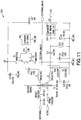
- An exemplary multi-button activation sense circuit 300 will now be described in relation to FIG. 11 .
- An oscillator generator 302 is provided which produces a sine wave, although other waveforms could be used, operates drive transistors Q2 and Q3. The configuration of these transistors operates as a voltage source, although alternately, a current source configuration could be used.
- the frequency of the oscillator generator 302 is chosen so that it is easily distinguished from the operating frequency of the electrosurgical generator as well as any electrosurgical power modulation frequencies.
- the output of the drive transistors Q2, Q3 operates the series resonant circuit consisting of components capacitor C17, inductor L3, the secondary of transformer T2, inductor L4, resistor R18 and resistor R2. This resonant circuit, and particularly the values of inductors L3 and L4, prevents the electrosurgical power signal from being picked up by the activation sense circuit.
- noise filtering capacitors Due to the wide spectrum of noise frequencies produced by the electrosurgical arc, several noise filtering capacitors are used, including C23 and C27, C25, C10 and C18, and C15 and C21. These last two filter capacitors C15 and C21 also prevent any stray signals produced by this circuit from entering the electrosurgical system power supply, as well as preventing stray signals which may be present in the system power supply from affecting this activation circuit.
- isolation barrier transformer T2 The current sensed by isolation barrier transformer T2 is sent to a voltage divider consisting of R2 and R18, whose output is subsequently rectified and filtered and sent to the ADC (not shown). This sensed current is also sent to the cut or coagulation activation circuit consisting of R13, D2 and the associated comparator 304.
- the circuit shown in FIG. 11 may be used to sense the activation, for example, of the cut pushbutton or the power-down pushbutton.
- a duplicate circuit would be used then to sense the coagulation or power-up pushbutton, as shown in FIGS. 12A-12C .
- an electrosurgical system 400 including an electrosurgical pencil 401 coupled to an electrosurgical generator 411 via a cable 403.
- the electrosurgical pencil 401 includes four buttons or switches, i.e., button 414 for CUT, button 416 for COAG, button 424 for power down and button 426 for power up.
- the cable 403 includes a connector 412, e.g., a three pin connector, for coupling the pencil 401 to the electrosurgical generator 411 via an appropriate port or receptacle 405.
- the electrosurgical generator 411 includes a housing 430 having a front panel face 432 which includes an input section 434, e.g. a touchscreen, for entering commands and data into the generator and various level controls 436 with corresponding indicators 438.
- the electrosurgical generator 411 further includes a receptacle section 440 which includes a On/Off switch 442, a return electrode receptacle 444, a monopolar footswitching receptacle 446, monopolar handswitching receptacle 405 and a bipolar handswitching receptacle 450.
- the electrosurgical generator 411 includes a controller 452 that controls a HV DC power supply 454 (which receives power from an external source) to supply electrosurgical energy being output from an RF output stage 456 via at least one conductor 403 to the handpiece 401 in FIG. 12A .
- a memory 453 is coupled to the controller 452 and is configured to store various control parameters such as, but not limited to, power curves for associated handpieces, predefined power limit controls, power level increment/decrement units, predetermined impedance values associated to a switch or function, etc.
- the electrosurgical generator 411 will indicate various operating conditions to an operator via an I/O interface 458 such as the input section 434, level controls 436 and indicators 438.
- the electrosurgical generator 411 may further include an audible indicator 460 to alert an operator to various conditions.
- the electrosurgical generator 411 includes two activation sense circuits, i.e., circuit 407 to sense the coagulation or power-up pushbutton and circuit 409 to sense the cut or power-down pushbutton.
- Each activation sense circuit generates two activation signals which are transmitted to a controller 452, e.g., a processor, in the electrosurgical generator 411 to affect a corresponding action.
- circuit 407 is configured to generate a COAG activation signal 413 and a power up activation signal 415 and circuit 409 is configured to generate a CUT activation signal 417 and a power down activation signal 419.
- the operation of circuits 407 and 409 are similar to that described in relation to the circuit 300 shown in FIG. 11 .
- buttons or switches may be implemented by the electrosurgical pencil 401 while a conventional three-pin connector 412 is employed. It is further to be appreciated that the activation sense circuits may be disposed in the electrosurgical generator 411 or may be configured as a separate module or device to be utilized with an electrosurgical generator.
- the power-up and power-down pushbuttons would also produce their own feedback cues which are easily distinguished from those associated with the cut and coagulation activation.
- the feedback cues may be in the form of a visual indictor, e.g., indicators 438, on the front panel 432 of the electrosurgical generator or in the form of a audible indictor, e.g., audible indicator 460, producing a sound from the electrosurgical generator.
- the electrosurgical generator could also have the capability to have pre-set limits for remote power-up or power-down activation so that the output power of the electrosurgical generator is not inadvertently raised to dangerously high levels, or reduced to levels that are ineffective.
- step 502 the incremental power control mode is selected from the generator control panel, e.g., input section 434.
- the controller determines if the power up button is activated in step 504. If the power up button is activated, the controller 452 increments a power level one unit, step 506.
- the controller 452 determines if the power up button is still activated, and if so, no further action is taken.
- the power up button must first be released, and if pressed again, another increment of one unit of the power level is taken. In this way, the power level will be incremented by as many units as the power up button is repeatedly pressed. For example, if the power up button is pressed three times, the power level will be increased by three units.
- the controller 452 determines the power up button is not activated in steps 504 and 508, the controller 452 performs similar steps for decrementing the power level in steps 510-514.
- the size of the increment/decrement unit is to be entered or adjusted at the control panel of the electrosurgical generator, for example, via level controls 436.
- the size of the increment/decrement unit may be programmed into the generator to be fixed.
- the generator may be programmed with a high and/or low power limit level, where when the limit level is reached, further button activations will have no effect.
- the generator includes an audible indicator 460 that is activated each time the power level is incremented or decremented.
- step 520 the continuous power control mode is selected from the generator control panel, e.g., input section 434.
- the controller 452 determines if the power up button is activated in step 522. If the power up button is activated, the controller 452 increments a power level one unit, step 524.
- the controller 452 determines if the power up button is still activated, and if so, the controller 452 initiates a time delay, step 528, before incrementing the power level one more unit.
- the duration of the time delay determines how fast the power level is incremented. A short time delay will cause the power level to be incremented rapidly as long as the power up button remains pushed. A longer delay will cause the power level to be incremented more slowly.
- the duration of the delay can either be set by the generator front panel, e.g., via input section 434 or level controls 436, or pre-set to a fixed value by the manufacturer.
- controller 452 determines the power up button is not activated in steps 522 and 526, the controller 452 performs similar steps for decrementing the power level in steps 530-536.
- the cut or coagulation mode can be implemented by pressing the appropriate button.
- the CUT or COAG button is activated or pressed, the power up and/or power down buttons will have no effect.
- Additional pushbuttons and functionality could be added to the electrosurgical hand piece using both the cut and coagulation lines, within the limits of user convenience, complexity, and safety.
- additional pushbuttons or switches could be used to adjust the gas flow rate as well as electrical beam power levels from the hand piece.
- an alternate embodiment may include a variable frequency oscillator generator.
- a variable frequency may be swept periodically through a given range of frequencies, or step through a given set of specific frequencies periodically.
- switches e.g., switches 225 or 227 shown in FIG. 9
- a resonant circuit or device is switched in and sensed by activation sensing circuit 300 in FIG. 11 , except that now the change in impedance is correlated with the specific frequency.
- the resonant circuits or devices attached to switches 225 and 227 in FIG. 9 are designed to have resonant frequencies of 30kHz and 35kHz respectively, then when oscillator generator 302 in FIG. 11 either sweeps through or steps through those frequencies and no change in impedance is detected by circuit 300 in FIG. 11 , then neither switch 225 nor 227 was activated. If, however, a change in impedance is detected when oscillator generator 302 is at 30kHz, then the circuit 300 will determine that switch 225 was activated. Similarly, if the oscillator generator 302 is at 35kHz and an impedance change is detected, then the circuit 300 will determine that switch 227 was activated.
- Electrosurgical processes essentially consist of an arc discharge into the operative site and produce a wide frequency spectrum of noise which varies considerably both in time and in amplitude.
- the resonant circuit can consist of either series or parallel combinations of a resistor, an inductor, and a capacitor, or it can be a resonant device such as a crystal, ceramic resonator, or similar electromechanical resonating component.
- the resonant frequencies are selected such that the resonant frequencies are easily distinguished from the electrosurgical power frequency and/or any power modulation frequencies that may be used.
- processor or “controller” should not be construed to refer exclusively to hardware capable of executing software, and may implicitly include, without limitation, digital signal processor ("DSP") hardware, read only memory (“ROM”) for storing software, random access memory (“RAM”), and nonvolatile storage.
- DSP digital signal processor
- ROM read only memory
- RAM random access memory
- any switches shown in the figures are conceptual only. Their function may be carried out through the operation of program logic, through dedicated logic, through the interaction of program control and dedicated logic, or even manually, the particular technique being selectable by the implementer as more specifically understood from the context.
Landscapes
- Health & Medical Sciences (AREA)
- Surgery (AREA)
- Engineering & Computer Science (AREA)
- Life Sciences & Earth Sciences (AREA)
- Biomedical Technology (AREA)
- Otolaryngology (AREA)
- Nuclear Medicine, Radiotherapy & Molecular Imaging (AREA)
- Plasma & Fusion (AREA)
- Physics & Mathematics (AREA)
- Heart & Thoracic Surgery (AREA)
- Medical Informatics (AREA)
- Molecular Biology (AREA)
- Animal Behavior & Ethology (AREA)
- General Health & Medical Sciences (AREA)
- Public Health (AREA)
- Veterinary Medicine (AREA)
- Surgical Instruments (AREA)
Description
- The present disclosure relates generally to electrosurgery and electrosurgical systems and apparatuses, and more particularly, to an electrosurgical apparatus with a multi-button handpiece.
- High frequency electrical energy has been widely used in surgery. Tissue is cut and bodily fluids are coagulated using electrosurgical energy generated by an electrosurgical unit (ESU), e.g., an electrosurgical generator, and delivered or applied to the tissue by an electrosurgical instrument, e.g., a handpiece.
- Electrosurgical instruments generally comprise "monopolar" devices or "bipolar" devices. Monopolar devices comprise an active electrode on the electrosurgical instrument with a return electrode attached to the patient. In monopolar electrosurgery, the electrosurgical energy flows through the active electrode on the instrument through the patient's body to the return electrode. Such monopolar devices are effective in surgical procedures where cutting and coagulation of tissue are required and where stray electrical currents do not pose a substantial risk to the patient.
- Bipolar devices comprise an active electrode and a return electrode on the surgical instrument. In a bipolar electrosurgical device, electrosurgical energy flows through the active electrode to the tissue of a patient through a short distance through the tissue to the return electrode. The electrosurgical effects are substantially localized to a small area of tissue that is disposed between the two electrodes on the surgical instrument. Bipolar electrosurgical devices have been found to be useful with surgical procedures where stray electrical currents may pose a hazard to the patient or where other procedural concerns require close proximity of the active and return electrodes. Surgical operations involving bipolar electrosurgery often require methods and procedures that differ substantially from the methods and procedures involving monopolar electrosurgery.
- Gas plasma is an ionized gas capable of conducting electrical energy. Plasmas are used in surgical devices to conduct electrosurgical energy to a patient. The plasma conducts the energy by providing a pathway of relatively low electrical resistance. The electrosurgical energy will follow through the plasma to cut, coagulate, desiccate, or fulgurate blood or tissue of the patient. There is no physical contact required between an electrode and the tissue treated.
- Electrosurgical systems that do not incorporate a source of regulated gas can ionize the ambient air between the active electrode and the patient. The plasma that is thereby created will conduct the electrosurgical energy to the patient, although the plasma arc will typically appear more spatially dispersed compared with systems that have a regulated flow of ionizable gas.
- Atmospheric pressure discharge cold plasma applicators have found use in a variety of applications including surface sterilization, hemostasis, and ablation of tumors. In the latter example, the process can be relatively slow, generate large volumes of noxious smoke with vaporized and charred tissue, and may cause collateral damage to surrounding healthy tissue when high power electrosurgical energy is used. Precision accuracy can also be a problem, due to the width of the plasma beam.
- The power of any electrosurgical unit (ESU) or RF-unit (radio frequency unit) is delivered to the patient tissue by an activation command, given by the surgeon. The command interface is usually switches (e.g., buttons), located in the activation accessories of the ESU, e.g., handles (hand-pieces), footswitches and other special instruments. A
conventional handle accessory 10 is illustrated inFIG. 1 and includes ahousing 2, anelectrode 8 and two buttons - one for CUT mode (button 14) and one for COAG mode (button 16). Typically, thebuttons button handle 10 uses 3 wires to connect to the ESU 11 viaconnector 12 andcable 13. - During the course of an electrosurgical procedure, the power setting of each mode may need to be changed several times to adapt to varying operative conditions. Conventionally, this is done by making adjustments on the control panel of the electrosurgical generator unit, and would either need the assistance of a nurse, or require the surgeon to leave the sterile field of the surgical site. It would be advantageous for the surgeon to be able to adjust the electrosurgical power on an as-needed basis by adding additional controls to the electrosurgical hand piece itself. However, additional buttons would require more control wires from the
handpiece 10 to theESU 11; for example, a handle with 3 buttons would require 4 control wires, a handle with 4 buttons would require 5 control wires, i.e., the number of required control wires = the number of buttons + 1. - Consequentially, more control wires in the
cable 13 between thehandpiece 10 and the ESU 11 has at least two disadvantages. First, additional control wires increases the complexity, and hence costs, of the connectors for the handpiece and for the front panel of the ESU. Increased cost is a critical issue in the case of disposable accessories. Secondly, more wires in the cable usually represents more stray capacitance to earth, hence higher leakage currents will be produced. Higher leakage currents are to be avoided when working with higher frequencies, e.g., up to 4 MHz. - Therefore, a need exists for a multi-button handpiece or accessory for controlling an electrosurgical unit or generator that employs a minimum number of control wires.
US 2003/050633 A1 discloses an intelligent selection system for operating an electrosurgical instrument for use by a surgeon that depends primarily on the surgical procedure to be employed. The operating mode as well as other operating parameters can be controlled by the handpiece chosen by the surgeon to perform the procedure. Each handpiece is customized to activate when operated one of several preset operating modes of the electrosurgical instrument. - Documents
EP 0 186 369 A1 ,DE 24 29 021 A1 ,US 2012/265196 A1 andUS 2009/275940 A1 disclose additional relevant background art. - The invention is defined in the appended
independent claim 1. Preferred embodiments are disclosed in the dependent claims. The present disclosure relates to an electrosurgical apparatus with a multi-button handpiece. - According to one aspect of the present disclosure, an electrosurgical apparatus is provided including a housing having a passage extending therethough, the housing having a proximal end and a distal end, the distal end configured to support an electrode; at least four switches disposed on a surface of the housing configured to be selectively activated by a user; and three wires connected between the housing and a connector, the connector configured to be operatively coupled to an electrosurgical generator, a first wire being coupled to the electrode and configured to receive electrosurgical energy from the electrosurgical generator, a second wire being coupled to a first switch and configured to generate a first activation signal and a third wire being coupled to a second switch and configured to generate a second activation signal, wherein a third and fourth switch are coupled to the first wire and the second or third wire via a respective reactive switching element configured to generate third and fourth activation signals.
- In one aspect, the at least four switches are configured as pushbuttons.
- In another aspect, each of the respective reactive switching elements is selected to generate a different impedance value.
- In yet another aspect, each of the respective reactive switching elements may include a parallel combination of a resistor and a capacitor, a series combination of a resistor and an inductor, a series combination of a resistor and a capacitor, a parallel combination of a resistor and an inductor, a capacitor or an inductor.
- In a further aspect, the connector includes a three pin connector.
- In another aspect, at least two switches of the at least four switches are coupled to a single rocker button.
- In another aspect of the present disclosure, electrosurgical apparatus includes an electrosurgical generator coupled to an electrical power supply configured to generate electrosurgical energy; a handpiece including a housing having a passage extending therethough, the housing having a proximal end and a distal end, the distal end configured to support an electrode; at least four switches disposed on a surface of the housing configured to be selectively activated by a user; and three wires connected between the housing and a connector, the connector configured to be operatively coupled to the electrosurgical generator, a first wire being coupled to the electrode and configured to receive electrosurgical energy from the electrosurgical generator, a second wire being coupled to a first switch and configured to generate a first activation signal and a third wire being coupled to a second switch and configured to generate a second activation signal, wherein a third and fourth switch are coupled to the first wire and the second or third wire via a respective reactive switching element configured to generate third and fourth activation signals; and an activation sense circuit configured to distinguish between the first, second, third and fourth activation signals and to execute a corresponding action.
- In one aspect, the at least one activation sense circuit includes an oscillator generator and at least one transistor configured to operate as a voltage or current source for the reactive switching elements.
- In another aspect, a frequency of the oscillator generator is different than an operating frequency of the electrosurgical generator.
- In a further aspect, each of the respective reactive switching elements is selected to generate a different impedance value.
- In yet another aspect, each of the first and second activation signals is a short circuit signal.
- In one aspect, the at least one activation sense circuit includes a comparator to compare each of the third and fourth activation signals to a predetermined value.
- In another aspect, the at least one activation sense circuit converts the third and fourth activation signals into a respective pulse width modulation (PWM) signal.
- According to another aspect of the present disclosure, an electrosurgical apparatus includes an electrosurgical generator coupled to an electrical power supply configured to generate electrosurgical energy; a handpiece including:a housing having a passage extending therethough, the housing having a proximal end and a distal end, the distal end configured to support an electrode; at least four switches disposed on a surface of the housing configured to be selectively activated by a user; and three wires connected between the housing and a connector, the connector configured to be operatively coupled to the electrosurgical generator, a first wire being coupled to the electrode and configured to receive electrosurgical energy from the electrosurgical generator, a second wire being coupled to a first switch and configured to generate a first activation signal and a third wire being coupled to a second switch and configured to generate a second activation signal, wherein a third and fourth switch are coupled to the first wire and the second or third wire via a respective resonant circuit configured to generate third and fourth activation signals; and at least one activation sense circuit configured to distinguish between the first, second, third and fourth activation signals and to execute a corresponding action.
In one aspect, the at least one activation sense circuit includes an oscillator generator and at least one transistor configured to operate as a voltage or current source for the resonant circuits. - In another aspect, each respective resonant circuit is configured for a different frequency.
- In a further aspect, the oscillator generator is a variable frequency oscillator generator configured to sweep through a predetermined range of frequencies, wherein the predetermined range of frequencies include the frequencies of the respective resonant circuits.
- The above and other aspects, features, and advantages of the present disclosure will become more apparent in light of the following detailed description when taken in conjunction with the accompanying drawings in which:
-
FIG. 1 is an illustration of an exemplary electrosurgical system in accordance with an embodiment of the present disclosure; -
FIG. 2 is an electrical schematic diagram of an electrosurgical handpiece in accordance with an embodiment of the present disclosure; -
FIG. 3 is a pushbutton activation sensing circuit in accordance with an embodiment of the present disclosure; -
FIG. 4 is an illustration of an activation sense output in accordance with an embodiment of the present disclosure; -
FIG. 5A is an illustration of an activation sensing circuit employing a voltage source with an amplitude detector in accordance with an embodiment of the present disclosure; -
FIG. 5B is an illustration of an activation sensing circuit employing a current source with an amplitude detector in accordance with an embodiment of the present disclosure; -
FIG. 6 is an illustration of an activation sensing circuit employing duty cycle measurement in accordance with an embodiment of the present disclosure; -
FIGS. 7A-7B illustrate input/output signals of the activation sensing circuit shown inFIG. 6 in accordance with one embodiment of the present disclosure; -
FIGS. 8A-8B illustrate input/output signals of the activation sensing circuit shown inFIG. 6 in accordance with another embodiment of the present disclosure; -
FIG. 9 is an electrical schematic diagram of an electrosurgical handpiece in accordance with another embodiment of the present disclosure; -
FIG. 9A is an electrical schematic diagram of an electrosurgical handpiece in accordance with a further embodiment of the present disclosure; -
FIG. 10 is an illustration of an activation sense output for multiple pushbuttons in accordance with an embodiment of the present disclosure; -
FIG. 11 is a multi-button activation sensing circuit in accordance with an embodiment of the present disclosure; -
FIGS. 12A-12C illustrate an electrosurgical system in accordance with an embodiment of the present disclosure; -
FIG. 13 is a flow chart illustrating an incremental power control mode in accordance with an embodiment of the present disclosure; and -
FIG. 14 is a flow chart illustrating a continuous power control mode in accordance with an embodiment of the present disclosure. - It should be understood that the drawing(s) is for purposes of illustrating the concepts of the disclosure and is not necessarily the only possible configuration for illustrating the disclosure.
- Preferred embodiments of the present disclosure will be described hereinbelow with reference to the accompanying drawings. In the following description, well-known functions or constructions are not described in detail to avoid obscuring the present disclosure in unnecessary detail. In the drawings and in the description which follow, the term "proximal", as is traditional, will refer to the end of the device, e.g., instrument, apparatus, applicator, handpiece, forceps, etc., which is closer to the user, while the term "distal" will refer to the end which is further from the user. Herein, the phrase "coupled" is defined to mean directly connected to or indirectly connected with through one or more intermediate components. Such intermediate components may include both hardware and software based components.
- An electrosurgical apparatus with a multi-button handpiece is provided. The electrosurgical apparatus of the present disclosure provides a significant advantage for a surgeon to be able to adjust electrosurgical power on an as-needed basis by adding additional controls to an electrosurgical handpiece itself. The additional controls can take the form of two new pushbuttons, or a two-position switch, one for power-up and another for power-down, in addition to, for example, cut and coagulation pushbuttons already present on an electrosurgical handpiece, e.g., an electrosurgical pencil. The techniques of the present disclosure provide a way that no additional signal lines, and associated connector pins would be needed as these would add to the overall cost of the hand piece assembly, where cost is a particularly sensitive aspect of disposable medical devices. By keeping the signal lines to a minimum, e.g., three signal lines, stray capacitance and therefore higher leakage currents can be avoided, which is especially problematic in electrosurgical generators that operate at higher frequencies, such as 4 MHz.
- Referring to
FIG. 2 , an electrical schematic diagram of an electrosurgical handpiece in accordance with an embodiment of the present disclosure is provided. Thehandpiece 100 includes ahousing 102 having a passage extending therethough, thehousing 102 having aproximal end 104 and adistal end 106. Thedistal end 106 of the housing is configured to support aconductive element 108, e.g., a blade electrode, for affecting a surgical procedure to tissue. Acable 110 couples theproximal end 104 of thehandpiece 100 to aconnector 112. Theconnector 112 is configured to be coupled to a corresponding connector on a face of the ESU. First andsecond buttons housing 102 to initiate different electrosurgical procedures. The first andsecond buttons - The
cable 110 carries three conductors or wires from theconnector 112 to thehandpiece 100. Afirst conductor 118, labeled ACTIVE inFIG. 2 , couples an RF or electrosurgical power output from the ESU to theblade electrode 108. One pole of eachswitch first conductor 118. Asecond conductor 120, labeled COAG inFIG. 2 , is coupled to a second pole of theswitch 117 controlled bybutton 116. Athird conductor 122, labeled CUT inFIG. 2 , is coupled to a second pole of theswitch 115 controlled bybutton 114. The cut and coagulation pushbuttons operate by making contact with the active electrode, which carries the operative electrosurgical power. This implementation then requires only three wires and an associated threepin connector 112, as illustrated inFIG. 2 , between thehandpiece 100 and ESU. - A means of isolation is necessary from the signal generated when either the cut or coagulation pushbuttons are activated and are connected to the
active power line 118 since the active power level carries very high voltages, incompatible with digital control logic levels. The means of isolation can be achieved with an isolation barrier transformer and associated activation circuit, for example, disposed in the electrosurgical generator. Pushbutton actuation is sensed using anactivation sense circuit 130, which is illustrated inFIG. 3 . Theactivation sense circuit 130 includes anoscillator 132 which drives the secondary 136 of anisolation transformer T1 134. The frequency of theoscillator 132 is chosen so that it is significantly different than operating frequency of the electrosurgical generator, to prevent one from being mistaken from the other. A pushbutton PB1 (e.g.,button 114 or button 116) is connected across the primary 138 of theisolation transformer T1 134, by way of the active line and either the cut or coagulation lines. The alternating current flowing in the secondary 136 of theisolation transformer T1 134 is monitored by resistor R1 and is at a given quiescent level when the pushbutton PB1 is not activated, and the primary 138 of theisolation transformer 134 is open-circuit. This quiescent current is rectified and filtered by diode D1 and filter capacitor C1, producing a quiescent DC level. However, when the pushbutton PB1 is activated, the pushbutton or switch short-circuits the primary 138 of theisolation transformer T1 134, causing a substantial increase in the current of the secondary 136 of theisolation transformer 134 that results in an increase in the DC level at theactivation sense output 140, which is illustrated inFIG. 4 . It is this increase in secondary current that is sensed and recognized as a valid pushbutton activation via a controller or other circuitry in the ESU. A complete set of an isolation transformer and activation circuit is needed for each pushbutton. - When the activation of a pushbutton is sensed, in addition to commanding the associated function in the electrosurgical generator, such as cut or coagulation, a feedback signal may also be produced to alert the user of the activation. Both visual feedback, in the form of an indicator light on the electrosurgical generator front panel, and an auditory tone are produced, and each are unique and easily distinguished for either cut or coagulation activation.
- Additional pushbuttons can be added in parallel with the cut and coagulation pushbuttons, but instead switch in a specific impedance value, other than the short circuit value if the cut or coagulation pushbuttons were activated. An exemplary handpiece including two additional pushbuttons for power-up and power-down functions is illustrated in
FIGS. 9, 9A and12A , the details of which will be described below. - Referring to the
activation sense circuit 130 inFIG. 3 , instead of introducing a short circuit of pushbutton PB1 introduced into the primary 138 oftransformer T1 134, anactivation sense circuit 145 may include areactive element 146 that can be switched-in as shown inFIG. 5A . This will cause an increase in the secondary current oftransformer T1 134 which is somewhat less than the short circuit value, as shown inFIG. 4 . This increased secondary current value will depend on the impedance value of thereactive element 146 at a given frequency. Theactivation sense circuit 145 ofFIG. 5A may also include anoptional filter circuit 148 on theprimary side 138 of thetransformer 134 which is used to both prevent the electrosurgical power signal and any noise generated by the electrosurgical discharge arc, from interfering with the recognition of an activation signal. Theoscillator 150 inFIG. 5A is configured as a voltage source, while the oscillator may be configured as acurrent source 152 as shown inactivation sense circuit 154 inFIG. 5B . Capacitor Cd inFIGS. 5A and 5B is used to block any DC component which may be present in the oscillator output. The output fromdetector 156 in eitherFIG. 5A and 5B is further filtered and sent to an analog to digital converter (ADC) (not shown) whose value is then used to determine if the pushbutton PB1 is pressed by the electrosurgicalgenerator system controller 158 by comparing it to a preset fixed value. Alternately, the filtered output of thedetector 156 can be sent to a comparator which compares it to a fixed reference voltage, and then determine if the pushbutton PB1 is pressed. - In an alternate configuration as shown in
FIG. 6 ,activation sense circuit 160 converts the amplitude sensed at the secondary 136 of thetransformer 134 into a pulse width modulation (PWM) signal with post measurement of the duty cycle. Theactiviation sense circuit 160 utilizes acomparator 162 to sense the change in current in the secondary 136 of thetransformer 134. The amplitude of the voltage sensed in the secondary 136 of thetransformer 134 is compared to a reference voltage (VREF). When the instantaneous sensed voltage exceeds the reference voltage (VREF), the output of thecomparator 162 goes to a logic "1" and is at a logic "0" otherwise. The higher the peak amplitude of the sensed voltage, the longer it will be above the reference voltage, and the longer the output of thecomparator 162 will remain at a logic "1". This results in a pulse whose width is related to the amplitude of the sensed voltage. The higher the sensed peak voltage is, the wider the pulse. This is illustrated inFIG. 7A and the resulting comparator output inFIG. 7B for a lower sensed peak voltage, and for a higher sensed peak voltage inFIG. 8A and 8B , respectively. This varying pulse width output from thecomparator 162 is then measured by thecontroller 158 of the electrosurgical generator system and compared to preset values to determine if the pushbutton PB1 was pressed or is open. This substantially reduces the cost and complexity of an ADC-based configuration. - It is to be appreciated that the oscillator source, e.g., a voltage or current source, may be a self-oscillating circuit, for example, a Colpitz oscillator.
- Referring to
FIG. 9 , an electrical schematic diagram of anelectrosurgical handpiece 200 in accordance with another embodiment of the present disclosure is provided. Thehandpiece 200 includes ahousing 202 having a passage extending therethough, thehousing 202 having aproximal end 204 and adistal end 206. Thedistal end 206 of the housing is configured to support aconductive element 208, e.g., a blade electrode, for affecting a surgical procedure to tissue. Acable 210 couples theproximal end 204 of thehandpiece 200 to aconnector 212. Theconnector 212 is configured to be coupled to a corresponding connector on a face of the ESU. First andsecond buttons housing 202 to initiate different electrosurgical procedures. The first andsecond buttons fourth buttons housing 202. The third andfourth buttons - It is to be appreciated that although
buttons buttons switches FIG. 9A , rocker button or switch 250 is disposed on the outer surface ofhousing 202. Therocker button 250 includes firstinclined surface 252 and secondinclined surface 254 which are configured to pivot aboutcentral point 256, as is know in the art. The firstinclined surface 252 is coupled to switch 225 (e.g., power down) and the second inclined surface is coupled to switch 227 (e.g., power up). Upon pressing either the first or second inclined surface by a user, the corresponding switch closes. Therocker button 250 may be spring-loaded so that it returns to a unactivated state, upon a release in pressure by the user, i.e., when neither the first nor second inclined surface is pressed,switch 225 and switch 227 are open. Other types of buttons and/or devices to activateswitches - Similar to the embodiment shown in
FIG. 2 , thecable 210 carries three conductors or wires from theconnector 212 to thehandpiece 200. Afirst conductor 218, labeled ACTIVE inFIG. 9 , couples an RF or electrosurgical power output from the ESU to theblade electrode 208. One pole of eachswitch first conductor 218. Asecond conductor 220, labeled COAG/POWUP inFIG. 9 , is coupled to a second pole of the 217 switch controlled bybutton 216. Athird conductor 222, labeled CUT/POWDN inFIG. 9 , is coupled to a second pole of the 215 switch controlled bybutton 214. - It is to be appreciated that the third and
fourth switches conductors FIG. 9 ,switch 225 has one pole coupled toconductor 218 and the second pole coupled to theconductor 222 via areactive switching element 230, i.e., resistor R2 and capacitor C2. Theswitch 227 has one pole coupled toconductor 218 and the second pole coupled to theconductor 220 via reactive switching element 232, i.e., resistor R1 and capacitor C1. - The multi-button activation sensing circuit operates on a similar principle as described in relation to the circuit shown in
FIG. 3 , but now looks for a specific change in impedance, while still being compatible with the cut and coagulation pushbutton operation. Values for resistors and capacitors R1, C1 and R2, C2 shown inFIG. 9 are selected so that the change in impedance when the associated pushbutton is activated is easily distinguished from the short circuit when either the cut or coagulation pushbuttons are pressed. Exemplary values for resistors R1, R2 may be 100 ohms while capacitors C1, C2 may be 2.2 nF; however, these values are only exemplary values and other values of the resistors and capacitors are contemplated to be within the scope of the present disclosure. The cut and coagulation pushbuttons take priority, since once they are pressed, their short circuit makes it impossible to see either resistor and capacitor combination R1, C1 or R2, C2. As a result, the power level of the electrosurgical generator cannot be changed while a cut or coagulation activation is in progress, i.e., pressing the power upbutton 226 or power downbutton 224 will have no effect while theCUT button 214 orCOAG button 216 is pressed. - Capacitors C1 and C2 shown in
FIG. 9 are placed in parallel with resistors R1 and R2 respectively, both to reduce noise pickup, especially in the case of long cables between the electrosurgical hand piece and the electrosurgical generator, and to reduce the power dissipation in resistors R1 and R2. Without these capacitors, the power dissipation would be several Watts which would require physically large resistors in an electrosurgical hand piece where space is already limited. Since the impedance is being sensed through the parallel combination of resistor R1 and capacitor C1 and the parallel combination of resistor R2 and capacitor C2, it is to be appreciated that this change in impedance could also be affected by other reactive switching elements such as a series combination of a resistor and a capacitor, a series combination of a resistor and an inductor, a parallel combination of a resistor and an inductor, or a capacitor or an inductor alone. - Potentially any number of additional pushbuttons could be added to the electrosurgical hand piece by using other resistor and capacitor values sufficiently different that the change in impedance could be reliably recognized by a multi-button activation sensing circuit, given the constraints of the electrical noise present in an electrosurgical environment. Electrosurgical processes essentially consist of an arc discharge into the operative site and produce a wide frequency spectrum of noise which varies considerably both in time and in amplitude. An example of multi-button sensing is illustrated in
FIG. 10 . - In one embodiment, the electrosurgical generator coupled to the
electrosurgical apparatus 200 includes an activation sense circuit configured to sense impedances values along the conductors ofcable 210 to determine which button or switch has been activated. The output of the activation sense circuit is sent to an analog to digital converter (ADC) which converts the different voltage levels into an equivalent digital representation. This digital value is compared by a controller, e.g., a microcontroller, in the electrosurgical generator to a previously stored value, and the appropriate action is taken. Alternately, the output of the activation sense circuit may be sent to an array of analog comparators, each comparing the activation sense output with a preset analog value. Again, when a particular activation sense output voltage level is recognized, the appropriate action is taken, e.g., increase a power level, decrease a power level, activate a cut mode, activate a coagulation mode, etc. - An exemplary multi-button
activation sense circuit 300 will now be described in relation toFIG. 11 . Anoscillator generator 302 is provided which produces a sine wave, although other waveforms could be used, operates drive transistors Q2 and Q3. The configuration of these transistors operates as a voltage source, although alternately, a current source configuration could be used. The frequency of theoscillator generator 302 is chosen so that it is easily distinguished from the operating frequency of the electrosurgical generator as well as any electrosurgical power modulation frequencies. The output of the drive transistors Q2, Q3 operates the series resonant circuit consisting of components capacitor C17, inductor L3, the secondary of transformer T2, inductor L4, resistor R18 and resistor R2. This resonant circuit, and particularly the values of inductors L3 and L4, prevents the electrosurgical power signal from being picked up by the activation sense circuit. - Due to the wide spectrum of noise frequencies produced by the electrosurgical arc, several noise filtering capacitors are used, including C23 and C27, C25, C10 and C18, and C15 and C21. These last two filter capacitors C15 and C21 also prevent any stray signals produced by this circuit from entering the electrosurgical system power supply, as well as preventing stray signals which may be present in the system power supply from affecting this activation circuit.
- The current sensed by isolation barrier transformer T2 is sent to a voltage divider consisting of R2 and R18, whose output is subsequently rectified and filtered and sent to the ADC (not shown). This sensed current is also sent to the cut or coagulation activation circuit consisting of R13, D2 and the associated
comparator 304. - The circuit shown in
FIG. 11 may be used to sense the activation, for example, of the cut pushbutton or the power-down pushbutton. A duplicate circuit would be used then to sense the coagulation or power-up pushbutton, as shown inFIGS. 12A-12C . - Referring to
FIGS. 12A-12C , anelectrosurgical system 400 is illustrated including anelectrosurgical pencil 401 coupled to anelectrosurgical generator 411 via acable 403. Theelectrosurgical pencil 401 includes four buttons or switches, i.e.,button 414 for CUT,button 416 for COAG,button 424 for power down andbutton 426 for power up. Thecable 403 includes aconnector 412, e.g., a three pin connector, for coupling thepencil 401 to theelectrosurgical generator 411 via an appropriate port orreceptacle 405. - Referring to
FIGS. 12B and 12C , anexemplary electrosurgical generator 411 in accordance with the present disclosure is illustrated. Theelectrosurgical generator 411 includes ahousing 430 having afront panel face 432 which includes aninput section 434, e.g. a touchscreen, for entering commands and data into the generator and various level controls 436 withcorresponding indicators 438. Theelectrosurgical generator 411 further includes areceptacle section 440 which includes a On/Off switch 442, areturn electrode receptacle 444, amonopolar footswitching receptacle 446,monopolar handswitching receptacle 405 and abipolar handswitching receptacle 450. Internally, theelectrosurgical generator 411 includes acontroller 452 that controls a HV DC power supply 454 (which receives power from an external source) to supply electrosurgical energy being output from anRF output stage 456 via at least oneconductor 403 to thehandpiece 401 inFIG. 12A . Amemory 453 is coupled to thecontroller 452 and is configured to store various control parameters such as, but not limited to, power curves for associated handpieces, predefined power limit controls, power level increment/decrement units, predetermined impedance values associated to a switch or function, etc. Theelectrosurgical generator 411 will indicate various operating conditions to an operator via an I/O interface 458 such as theinput section 434, level controls 436 andindicators 438. Theelectrosurgical generator 411 may further include anaudible indicator 460 to alert an operator to various conditions. - In one embodiment, the
electrosurgical generator 411 includes two activation sense circuits, i.e.,circuit 407 to sense the coagulation or power-up pushbutton andcircuit 409 to sense the cut or power-down pushbutton. Each activation sense circuit generates two activation signals which are transmitted to acontroller 452, e.g., a processor, in theelectrosurgical generator 411 to affect a corresponding action. For example,circuit 407 is configured to generate aCOAG activation signal 413 and a power upactivation signal 415 andcircuit 409 is configured to generate aCUT activation signal 417 and a power downactivation signal 419. The operation ofcircuits circuit 300 shown inFIG. 11 . - It is to be appreciated that by employing the activation sense circuits of the present disclosure four buttons or switches may be implemented by the
electrosurgical pencil 401 while a conventional three-pin connector 412 is employed. It is further to be appreciated that the activation sense circuits may be disposed in theelectrosurgical generator 411 or may be configured as a separate module or device to be utilized with an electrosurgical generator. - Just as the electrosurgical generator produces both visual and audible feedback cues when the cut or coagulation pushbuttons are activated, the power-up and power-down pushbuttons would also produce their own feedback cues which are easily distinguished from those associated with the cut and coagulation activation. For example, the feedback cues may be in the form of a visual indictor, e.g.,
indicators 438, on thefront panel 432 of the electrosurgical generator or in the form of a audible indictor, e.g.,audible indicator 460, producing a sound from the electrosurgical generator. - The electrosurgical generator could also have the capability to have pre-set limits for remote power-up or power-down activation so that the output power of the electrosurgical generator is not inadvertently raised to dangerously high levels, or reduced to levels that are ineffective.
- Different methods of remote power increase or decrease, via the buttons of the handpiece, may be employed. For example, a single depression of the power-up pushbutton may increase the electrosurgical generator's power output by a pre-set fixed amount. A subsequent depression of this pushbutton would increase the power output again by the same amount. An exemplary incremental power control mode is illustrated in
FIG. 13 . Initially, instep 502, the incremental power control mode is selected from the generator control panel, e.g.,input section 434. Next, the controller determines if the power up button is activated instep 504. If the power up button is activated, thecontroller 452 increments a power level one unit, step 506. Atstep 508, thecontroller 452 determines if the power up button is still activated, and if so, no further action is taken. The power up button must first be released, and if pressed again, another increment of one unit of the power level is taken. In this way, the power level will be incremented by as many units as the power up button is repeatedly pressed. For example, if the power up button is pressed three times, the power level will be increased by three units. - If the
controller 452 determines the power up button is not activated insteps controller 452 performs similar steps for decrementing the power level in steps 510-514. It is to be appreciated that the size of the increment/decrement unit is to be entered or adjusted at the control panel of the electrosurgical generator, for example, via level controls 436. In another embodiment, the size of the increment/decrement unit may be programmed into the generator to be fixed. In another embodiment, the generator may be programmed with a high and/or low power limit level, where when the limit level is reached, further button activations will have no effect. In a further embodiment, the generator includes anaudible indicator 460 that is activated each time the power level is incremented or decremented. - Alternately, a single depression of this pushbutton would again increase the output power by a fixed amount, but continuing to hold it down would continue to advance the power setting, with the appropriate visual and audible feedback cues being issued. An exemplary continuous power control mode is illustrated in
FIG. 14 . Initially, instep 520, the continuous power control mode is selected from the generator control panel, e.g.,input section 434. Next, thecontroller 452 determines if the power up button is activated instep 522. If the power up button is activated, thecontroller 452 increments a power level one unit,step 524. Atstep 526, thecontroller 452 determines if the power up button is still activated, and if so, thecontroller 452 initiates a time delay,step 528, before incrementing the power level one more unit. The duration of the time delay determines how fast the power level is incremented. A short time delay will cause the power level to be incremented rapidly as long as the power up button remains pushed. A longer delay will cause the power level to be incremented more slowly. The duration of the delay can either be set by the generator front panel, e.g., viainput section 434 or level controls 436, or pre-set to a fixed value by the manufacturer. - If the
controller 452 determines the power up button is not activated insteps controller 452 performs similar steps for decrementing the power level in steps 530-536. - It is to be appreciated that once the power level is set, for example, by the methods described in relation to
FIGS. 13 and14 , the cut or coagulation mode can be implemented by pressing the appropriate button. As described above, once the CUT or COAG button is activated or pressed, the power up and/or power down buttons will have no effect. - Additional pushbuttons and functionality could be added to the electrosurgical hand piece using both the cut and coagulation lines, within the limits of user convenience, complexity, and safety. For example, in plasma beam-type electrosurgical devices, additional pushbuttons or switches could be used to adjust the gas flow rate as well as electrical beam power levels from the hand piece.
- While the
oscillator generator 302 inFIG. 11 operates at one fixed frequency, an alternate embodiment may include a variable frequency oscillator generator. Such a variable frequency may be swept periodically through a given range of frequencies, or step through a given set of specific frequencies periodically. When additional switches (e.g., switches 225 or 227 shown inFIG. 9 ) are activated, a resonant circuit or device is switched in and sensed byactivation sensing circuit 300 inFIG. 11 , except that now the change in impedance is correlated with the specific frequency. - For example, if the resonant circuits or devices attached to
switches FIG. 9 are designed to have resonant frequencies of 30kHz and 35kHz respectively, then whenoscillator generator 302 inFIG. 11 either sweeps through or steps through those frequencies and no change in impedance is detected bycircuit 300 inFIG. 11 , then neither switch 225 nor 227 was activated. If, however, a change in impedance is detected whenoscillator generator 302 is at 30kHz, then thecircuit 300 will determine thatswitch 225 was activated. Similarly, if theoscillator generator 302 is at 35kHz and an impedance change is detected, then thecircuit 300 will determine thatswitch 227 was activated. - Potentially any number of additional pushbuttons could be added to the electrosurgical hand piece by using other resonant circuit or device values sufficiently different that the change in impedance could be reliably recognized by a multi-button activation sensing circuit, given the constraints of the electrical noise present in an electrosurgical environment. Electrosurgical processes essentially consist of an arc discharge into the operative site and produce a wide frequency spectrum of noise which varies considerably both in time and in amplitude.
- The resonant circuit can consist of either series or parallel combinations of a resistor, an inductor, and a capacitor, or it can be a resonant device such as a crystal, ceramic resonator, or similar electromechanical resonating component. The resonant frequencies are selected such that the resonant frequencies are easily distinguished from the electrosurgical power frequency and/or any power modulation frequencies that may be used.
- It is to be appreciated that the various features shown and described are interchangeable, that is, a feature shown in one embodiment may be incorporated into another embodiment.
- It will be appreciated by those skilled in the art that the block diagrams presented herein represent conceptual views of illustrative circuitry embodying the principles of the disclosure. Similarly, it will be appreciated that any flow charts, flow diagrams, state transition diagrams, pseudo-code, and the like represent various processes which may be substantially represented in computer readable media and so executed by a computer or processor, whether or not such computer or processor is explicitly shown.
- The functions of the various elements shown in the figures may be provided through the use of dedicated hardware as well as hardware capable of executing software in association with appropriate software. When provided by a processor, the functions may be provided by a single dedicated processor, by a single shared processor, or by a plurality of individual processors, some of which may be shared. Moreover, explicit use of the term "processor" or "controller" should not be construed to refer exclusively to hardware capable of executing software, and may implicitly include, without limitation, digital signal processor ("DSP") hardware, read only memory ("ROM") for storing software, random access memory ("RAM"), and nonvolatile storage.
- Other hardware, conventional and/or custom, may also be included. Similarly, any switches shown in the figures are conceptual only. Their function may be carried out through the operation of program logic, through dedicated logic, through the interaction of program control and dedicated logic, or even manually, the particular technique being selectable by the implementer as more specifically understood from the context.
Claims (15)
- An electrosurgical apparatus (200) comprising:a housing (202) having a passage extending therethough, the housing (202) having a proximal end (204) and a distal end (206), the distal end (206) configured to support an electrode (208);at least four switches (215, 217, 225, 227) disposed on a surface of the housing (202) configured to be selectively activated by a user; andthree wires (218, 220, 222) connected between the housing (202) and a connector (212), the connector (212) configured to be operatively coupled to an electrosurgical generator, a first wire (218) being coupled to the electrode (208) and configured to receive electrosurgical energy from the electrosurgical generator, a second wire (222) being coupled to a first switch (215) of the at least four switches and configured to generate a first activation signal and a third wire (220) being coupled to a second switch (217) of the at least four switches and configured to generate a second activation signal,wherein a third and fourth switch (225, 227) of the at least four switches are coupled to the first wire (218) and the second (222) or third wire (220) via a respective reactive switching element (230, 232) configured to generate third and fourth activation signals.
- The electrosurgical apparatus (200) as in claim 1, wherein the at least four switches (215, 217, 225, 227) are configured as pushbuttons (214, 216, 224, 226).
- The electrosurgical apparatus (200) as in claim 1 or 2, wherein each of the respective reactive switching elements (230, 232) is selected to generate a different impedance value.
- The electrosurgical apparatus (200) as in any of claims 1-3, wherein each of the first and second activation signals is a short circuit signal.
- The electrosurgical apparatus (200) as in any of claims 1-4, wherein each of the respective reactive switching elements (230, 232) is a parallel combination of a resistor and a capacitor.
- The electrosurgical apparatus (200) as in any of claims 1-4, wherein each of the respective reactive switching elements (230, 232) is a series combination of a resistor and an inductor.
- The electrosurgical apparatus (200) as in any of claims 1-4, wherein each of the respective reactive switching elements (230, 232) is a series combination of a resistor and a capacitor.
- The electrosurgical apparatus (200) as in any of claims 1-4, wherein each of the respective reactive switching elements (230, 232) is a parallel combination of a resistor and an inductor.
- The electrosurgical apparatus (200) as in any of claims 1-4, wherein each of the respective reactive switching elements (230, 232) is a capacitor.
- The electrosurgical apparatus (200) as in any of claims 1-4, wherein each of the respective reactive switching elements (230, 232) is an inductor.
- The electrosurgical apparatus (200) as in any of claims 1-10, wherein the connector (212) includes a three pin connector.
- The electrosurgical apparatus (200) as in any of claims 1-11, further comprising at least one activation sense circuit (300) configured to distinguish between the first, second, third and fourth activation signals and to execute a corresponding action.
- The electrosurgical apparatus (200) as in claim 12, wherein the at least one activation sense circuit (300) includes an oscillator generator (302) and at least one transistor (Q2, Q3) configured to operate as a voltage or current source for the reactive switching elements (230, 232).
- The electrosurgical apparatus (200) as in claim 12, wherein the at least one activation sense circuit (300) includes a comparator (304) to compare each of the third and fourth activation signals to a predetermined value.
- The electrosurgical apparatus (200) as in claim 12, wherein the at least one activation sense circuit (160) converts the third and fourth activation signals into a respective pulse width modulation (PWM) signal.
Priority Applications (1)
| Application Number | Priority Date | Filing Date | Title |
|---|---|---|---|
| EP19166697.3A EP3536273B1 (en) | 2013-03-13 | 2013-10-24 | Multi-button electrosurgical apparatus |
Applications Claiming Priority (2)
| Application Number | Priority Date | Filing Date | Title |
|---|---|---|---|
| US13/802,572 US9144453B2 (en) | 2010-11-08 | 2013-03-13 | Multi-mode electrosurgical apparatus |
| US13/966,034 US8998899B2 (en) | 2010-11-08 | 2013-08-13 | Multi-button electrosurgical apparatus |
Related Child Applications (1)
| Application Number | Title | Priority Date | Filing Date |
|---|---|---|---|
| EP19166697.3A Division EP3536273B1 (en) | 2013-03-13 | 2013-10-24 | Multi-button electrosurgical apparatus |
Publications (2)
| Publication Number | Publication Date |
|---|---|
| EP2792326A1 EP2792326A1 (en) | 2014-10-22 |
| EP2792326B1 true EP2792326B1 (en) | 2019-04-10 |
Family
ID=49517239
Family Applications (2)
| Application Number | Title | Priority Date | Filing Date |
|---|---|---|---|
| EP19166697.3A Active EP3536273B1 (en) | 2013-03-13 | 2013-10-24 | Multi-button electrosurgical apparatus |
| EP13005083.4A Active EP2792326B1 (en) | 2013-03-13 | 2013-10-24 | Multi-button electrosurgical apparatus |
Family Applications Before (1)
| Application Number | Title | Priority Date | Filing Date |
|---|---|---|---|
| EP19166697.3A Active EP3536273B1 (en) | 2013-03-13 | 2013-10-24 | Multi-button electrosurgical apparatus |
Country Status (3)
| Country | Link |
|---|---|
| US (2) | US8998899B2 (en) |
| EP (2) | EP3536273B1 (en) |
| CN (1) | CN104042325B (en) |
Families Citing this family (51)
| Publication number | Priority date | Publication date | Assignee | Title |
|---|---|---|---|---|
| DE102008039884A1 (en) * | 2008-08-27 | 2010-03-04 | Erbe Elektromedizin Gmbh | Electrosurgical HF generator |
| US9050113B2 (en) | 2010-01-15 | 2015-06-09 | Medtronic Advanced Energy Llc | Electrosurgical devices, electrosurgical unit and methods of use thereof |
| US9060765B2 (en) | 2010-11-08 | 2015-06-23 | Bovie Medical Corporation | Electrosurgical apparatus with retractable blade |
| US9770285B2 (en) | 2010-11-08 | 2017-09-26 | Bovie Medical Corporation | System and method for identifying and controlling an electrosurgical apparatus |
| US9095333B2 (en) | 2012-07-02 | 2015-08-04 | Bovie Medical Corporation | Systems and methods of discriminating between argon and helium gases for enhanced safety of medical devices |
| US9144453B2 (en) | 2010-11-08 | 2015-09-29 | Bovie Medical Corporation | Multi-mode electrosurgical apparatus |
| US8998899B2 (en) | 2010-11-08 | 2015-04-07 | Bovie Medical Corporation | Multi-button electrosurgical apparatus |
| PL2497427T3 (en) * | 2011-03-10 | 2020-05-18 | Erbe Elektromedizin Gmbh | Surgical instrument with digital data interface |
| US9375250B2 (en) | 2012-04-09 | 2016-06-28 | Covidien Lp | Method for employing single fault safe redundant signals |
| EP3427682B1 (en) | 2013-03-15 | 2020-09-23 | Gyrus ACMI, Inc. (D.B.A. Olympus Surgical Technologies America) | Combination electrosurgical device |
| WO2014152433A1 (en) | 2013-03-15 | 2014-09-25 | GYRUS ACMI, INC. (d/b/a OLYMPUS SURGICAL TECHNOLOGIES AMERICA) | Combination electrosurgical device |
| EP2974682B1 (en) | 2013-03-15 | 2017-08-30 | Gyrus ACMI, Inc. | Combination electrosurgical device |
| EP2967720B1 (en) | 2013-03-15 | 2017-05-31 | Gyrus Acmi Inc. | Offset forceps |
| US9763730B2 (en) | 2013-03-15 | 2017-09-19 | Gyrus Acmi, Inc. | Electrosurgical instrument |
| US11344382B2 (en) | 2014-01-24 | 2022-05-31 | Elucent Medical, Inc. | Systems and methods comprising localization agents |
| EP3052041B1 (en) * | 2014-08-20 | 2017-04-12 | Gyrus ACMI, Inc. (D.B.A. Olympus Surgical Technologies America) | Multi-mode combination electrosurgical device |
| WO2016070013A1 (en) | 2014-10-31 | 2016-05-06 | Medtronic Advanced Energy Llc | Fingerswitch circuitry to reduce rf leakage current |
| EP3250141B1 (en) | 2015-01-28 | 2023-10-11 | Apyx Medical Corporation | Cold plasma electrosurgical apparatus with bent tip applicator |
| WO2016151526A1 (en) * | 2015-03-24 | 2016-09-29 | Paul Weber | Electrosurgical switch assembly and related systems and methods |
| US10327833B2 (en) * | 2015-03-24 | 2019-06-25 | Tdm Surgitech, Inc. | Electrosurgical switch assembly and related systems and methods |
| US11446078B2 (en) | 2015-07-20 | 2022-09-20 | Megadyne Medical Products, Inc. | Electrosurgical wave generator |
| EP3132765B1 (en) * | 2015-08-21 | 2022-03-30 | Erbe Elektromedizin GmbH | Coagulation and dissection instrument with improved control |
| US9730764B2 (en) | 2015-10-02 | 2017-08-15 | Elucent Medical, Inc. | Signal tag detection components, devices, and systems |
| WO2017059228A1 (en) | 2015-10-02 | 2017-04-06 | Elucent Medical, Inc. | Signal tag detection components, devices, and systems |
| EP4302720A3 (en) | 2015-10-02 | 2024-03-20 | Elucent Medical, Inc. | Signal tag detection systems |
| GB2548382B (en) * | 2016-03-16 | 2019-04-03 | Fourth State Medicine Ltd | Plasma generation |
| US11510730B2 (en) | 2016-03-26 | 2022-11-29 | Paul Joseph Weber | Apparatus and methods for minimally invasive dissection and modification of tissues |
| US10893899B2 (en) | 2016-03-26 | 2021-01-19 | Paul Weber | Apparatus and systems for minimally invasive dissection of tissues |
| US10603101B2 (en) | 2016-03-26 | 2020-03-31 | Paul Joseph Weber | Apparatus, systems and methods for minimally invasive dissection of tissues |
| WO2018027207A1 (en) * | 2016-08-04 | 2018-02-08 | Buffalo Filter Llc | Electrosurgical device |
| DE102016114537A1 (en) * | 2016-08-05 | 2018-02-08 | Aesculap Ag | Method and device for controlling the supply of energy to a medical instrument |
| EP3496623B1 (en) | 2016-08-12 | 2023-11-01 | Elucent Medical, Inc. | Surgical device guidance and monitoring systems |
| WO2018140944A1 (en) | 2017-01-30 | 2018-08-02 | Bovie Medical Corporation | Electrosurgical apparatus with flexible shaft |
| US11877788B2 (en) | 2017-05-30 | 2024-01-23 | Apyx Medical Corporation | Electrosurgical apparatus with robotic tip |
| US11648047B2 (en) | 2017-10-06 | 2023-05-16 | Vive Scientific, Llc | System and method to treat obstructive sleep apnea |
| US10667834B2 (en) | 2017-11-02 | 2020-06-02 | Gyrus Acmi, Inc. | Bias device for biasing a gripping device with a shuttle on a central body |
| US11298801B2 (en) | 2017-11-02 | 2022-04-12 | Gyrus Acmi, Inc. | Bias device for biasing a gripping device including a central body and shuttles on the working arms |
| US11383373B2 (en) | 2017-11-02 | 2022-07-12 | Gyms Acmi, Inc. | Bias device for biasing a gripping device by biasing working arms apart |
| WO2019134078A1 (en) * | 2018-01-03 | 2019-07-11 | Bio-Medical Engineering (HK) Limited | Electrosurgical systems and methods of configuring the same |
| US11197708B2 (en) * | 2018-02-28 | 2021-12-14 | Gyrus Acmi, Inc. | Plasma generator configured for use with an auxiliary device |
| GB2571566B (en) * | 2018-03-01 | 2022-03-16 | Cmr Surgical Ltd | Electrosurgical connection unit |
| US10278779B1 (en) | 2018-06-05 | 2019-05-07 | Elucent Medical, Inc. | Exciter assemblies |
| CN108969092A (en) * | 2018-07-03 | 2018-12-11 | 杭州埃杜医疗科技有限公司 | A kind of low temperature radio frequency plasma surgery systems |
| PL3639779T3 (en) * | 2018-10-16 | 2022-11-21 | Erbe Elektromedizin Gmbh | Instrument for coagulation and dissection of biological tissue |
| US11399888B2 (en) | 2019-08-14 | 2022-08-02 | Covidien Lp | Bipolar pencil |
| USD914211S1 (en) * | 2019-08-18 | 2021-03-23 | Gregorio Hernandez Zendejas | Electrosurgical device |
| PL3895642T3 (en) * | 2020-04-14 | 2024-01-15 | Erbe Elektromedizin Gmbh | Device for coagulation and/or dissection of biological tissue and a method of operating a device. |
| EP4213758A4 (en) | 2020-09-16 | 2024-11-06 | Elucent Medical, Inc. | SYSTEMS AND METHODS INCLUDING CONNECTED LOCATION AGENTS |
| EP4124310B1 (en) * | 2021-07-26 | 2023-10-18 | Erbe Elektromedizin GmbH | Generator with feedback device |
| IT202100022169A1 (en) * | 2021-08-23 | 2023-02-23 | Led S P A | MONOPOLAR HANDPIECE WITH BUTTON CONTROL FOR ALL SURGERIES |
| WO2024009194A1 (en) * | 2022-07-05 | 2024-01-11 | Medtronic, Inc. | Electrosurgical energy harvesting |
Citations (6)
| Publication number | Priority date | Publication date | Assignee | Title |
|---|---|---|---|---|
| DE2429021A1 (en) * | 1974-06-18 | 1976-01-08 | Erbe Elektromedizin | Remote control for HF surgical instruments - uses cable with two conductors at most |
| EP0186369A1 (en) * | 1984-12-11 | 1986-07-02 | Valleylab, Inc. | Apparatus for processing requests made from the sterile field of a surgical procedure |
| EP0447121A2 (en) * | 1990-03-15 | 1991-09-18 | Valleylab, Inc. | Gas coagulation device |
| EP1795139A1 (en) * | 2005-12-12 | 2007-06-13 | Sherwood Services AG | Laparoscopic apparatus for performing electrosurgical procedures |
| US20090275940A1 (en) * | 2008-05-05 | 2009-11-05 | Malackowski Donald W | Surgical tool system including a tool and a control console, the console capable of reading data from a memory internal to the tool over the conductors over which power is sourced to the tool |
| US20120265196A1 (en) * | 2009-10-09 | 2012-10-18 | Ethicon Endo-Surgery, Inc. | Surgical generator for ultrasonic and electrosurgical devices |
Family Cites Families (90)
| Publication number | Priority date | Publication date | Assignee | Title |
|---|---|---|---|---|
| US1813902A (en) | 1928-01-18 | 1931-07-14 | Liebel Flarsheim Co | Electrosurgical apparatus |
| FR962088A (en) | 1943-12-23 | 1950-05-31 | ||
| US3239730A (en) | 1964-04-16 | 1966-03-08 | Farago George | Variable capacitor |
| US3801766A (en) | 1973-01-22 | 1974-04-02 | Valleylab Inc | Switching means for an electro-surgical device including particular contact means and particular printed-circuit mounting means |
| US4127110A (en) | 1976-05-24 | 1978-11-28 | Huntington Institute Of Applied Medical Research | Implantable pressure transducer |
| US4334539A (en) * | 1980-04-28 | 1982-06-15 | Cimarron Instruments, Inc. | Electrosurgical generator control apparatus |
| GB2090532B (en) | 1981-01-02 | 1985-09-18 | Goof Sven Karl Lennart | An electrosurgical apparatus |
| US4463759A (en) * | 1982-01-13 | 1984-08-07 | Garito Jon C | Universal finger/foot switch adaptor for tube-type electrosurgical instrument |
| US4545375A (en) | 1983-06-10 | 1985-10-08 | Aspen Laboratories, Inc. | Electrosurgical instrument |
| US4619258A (en) | 1984-03-02 | 1986-10-28 | Dart Industries Inc. | Electrosurgical pencil providing blade isolation |
| US4827927A (en) | 1984-12-26 | 1989-05-09 | Valleylab, Inc. | Apparatus for changing the output power level of an electrosurgical generator while remaining in the sterile field of a surgical procedure |
| US4632109A (en) | 1984-12-11 | 1986-12-30 | Valleylab, Inc. | Circuitry for processing requests made from the sterile field of a surgical procedure to change the output power level of an electrosurgical generator |
| US4625723A (en) | 1985-02-26 | 1986-12-02 | Medical Research Associates, Ltd. #1 | Pencil for electrosurgical generator |
| US4708137A (en) | 1985-05-20 | 1987-11-24 | Olympus Optical Co., Ltd. | High-frequency incision device |
| US5098430A (en) | 1990-03-16 | 1992-03-24 | Beacon Laboratories, Inc. | Dual mode electrosurgical pencil |
| US5306238A (en) | 1990-03-16 | 1994-04-26 | Beacon Laboratories, Inc. | Laparoscopic electrosurgical pencil |
| US5256138A (en) | 1990-10-04 | 1993-10-26 | The Birtcher Corporation | Electrosurgical handpiece incorporating blade and conductive gas functionality |
| DE4032471C2 (en) | 1990-10-12 | 1997-02-06 | Delma Elektro Med App | Electrosurgical device |
| US5207675A (en) | 1991-07-15 | 1993-05-04 | Jerome Canady | Surgical coagulation device |
| US5449356A (en) | 1991-10-18 | 1995-09-12 | Birtcher Medical Systems, Inc. | Multifunctional probe for minimally invasive surgery |
| US5383874A (en) | 1991-11-08 | 1995-01-24 | Ep Technologies, Inc. | Systems for identifying catheters and monitoring their use |
| US6770071B2 (en) | 1995-06-07 | 2004-08-03 | Arthrocare Corporation | Bladed electrosurgical probe |
| US5400267A (en) | 1992-12-08 | 1995-03-21 | Hemostatix Corporation | Local in-device memory feature for electrically powered medical equipment |
| US5693044A (en) | 1992-12-11 | 1997-12-02 | Cosmescu; Ioan | Telescopic surgical device and method therefor |
| US5425375A (en) | 1993-09-09 | 1995-06-20 | Cardiac Pathways Corporation | Reusable medical device with usage memory, system using same |
| EP0688536B1 (en) | 1994-03-23 | 2000-08-02 | Erbe Elektromedizin GmbH | Multifunctional instrument for ultrasonic surgery |
| US5529235A (en) | 1994-04-28 | 1996-06-25 | Ethicon Endo-Surgery, Inc. | Identification device for surgical instrument |
| US5660657A (en) | 1995-01-31 | 1997-08-26 | Kimberly-Clark Worldwide, Inc. | Composite method for fabricating garments |
| US6063081A (en) | 1995-02-22 | 2000-05-16 | Medtronic, Inc. | Fluid-assisted electrocautery device |
| US5626575A (en) | 1995-04-28 | 1997-05-06 | Conmed Corporation | Power level control apparatus for electrosurgical generators |
| US6458125B1 (en) | 1995-07-10 | 2002-10-01 | I. C. Medical, Inc. | Electro-surgical unit pencil apparatus and method therefor |
| US20030212393A1 (en) | 1996-01-05 | 2003-11-13 | Knowlton Edward W. | Handpiece with RF electrode and non-volatile memory |
| US6391027B1 (en) | 1996-07-04 | 2002-05-21 | Erbe Elektromedizin Gmbh | Gas-aided, axially displaceable surgical electrode |
| US5800427A (en) | 1996-12-26 | 1998-09-01 | Zamba; Gene | Electro-surgical blade |
| GB9708268D0 (en) | 1997-04-24 | 1997-06-18 | Gyrus Medical Ltd | An electrosurgical instrument |
| US6091048A (en) | 1997-05-16 | 2000-07-18 | Illinois Tool Works Inc. | Welding machine with automatic parameter setting |
| US6068627A (en) | 1997-12-10 | 2000-05-30 | Valleylab, Inc. | Smart recognition apparatus and method |
| US6068609A (en) | 1998-05-19 | 2000-05-30 | Douglas E. Ott | Method and apparatus for conditioning gas for medical procedures having humidity monitoring and recharge alert |
| US6193715B1 (en) | 1999-03-19 | 2001-02-27 | Medical Scientific, Inc. | Device for converting a mechanical cutting device to an electrosurgical cutting device |
| US6958063B1 (en) | 1999-04-22 | 2005-10-25 | Soring Gmbh Medizintechnik | Plasma generator for radio frequency surgery |
| US6409724B1 (en) | 1999-05-28 | 2002-06-25 | Gyrus Medical Limited | Electrosurgical instrument |
| US6237604B1 (en) | 1999-09-07 | 2001-05-29 | Scimed Life Systems, Inc. | Systems and methods for preventing automatic identification of re-used single use devices |
| DE60143368D1 (en) | 2000-02-16 | 2010-12-09 | Covidien Ag | Electrosurgical device with enriched inert gas |
| US7335199B2 (en) | 2000-02-22 | 2008-02-26 | Rhytec Limited | Tissue resurfacing |
| US6293945B1 (en) | 2000-03-06 | 2001-09-25 | Everest Medical Corporation | Electrosurgical instrument with suction capability |
| US20020056250A1 (en) | 2000-04-24 | 2002-05-16 | Cash David W. | Method and apparatus for increasing the capacity and stability of a single-pole tower |
| JP3897962B2 (en) | 2000-07-19 | 2007-03-28 | 株式会社モリタ製作所 | Identification-type instrument body, identification-type adapter, identification-type tube, and medical device using these |
| US20050075630A1 (en) | 2000-08-01 | 2005-04-07 | Dfine, Inc. | Voltage threshold ablation apparatus |
| DE10128377A1 (en) | 2001-06-08 | 2003-01-16 | Storz Endoskop Gmbh Schaffhaus | Electrosurgical device |
| US6652514B2 (en) | 2001-09-13 | 2003-11-25 | Alan G. Ellman | Intelligent selection system for electrosurgical instrument |
| GB0205109D0 (en) | 2002-03-05 | 2002-04-17 | Thermocore Medical Systems Sa | A catheter |
| EP1524946B1 (en) | 2002-07-25 | 2012-10-17 | Covidien AG | Electrosurgical pencil with drag sensing capability |
| DE10240847B4 (en) | 2002-09-04 | 2011-07-28 | Erbe Elektromedizin GmbH, 72072 | Applicator for an electrosurgical instrument |
| US7244257B2 (en) | 2002-11-05 | 2007-07-17 | Sherwood Services Ag | Electrosurgical pencil having a single button variable control |
| US7316682B2 (en) | 2002-12-17 | 2008-01-08 | Aaron Medical Industries, Inc. | Electrosurgical device to generate a plasma stream |
| US8057468B2 (en) | 2002-12-17 | 2011-11-15 | Bovie Medical Corporation | Method to generate a plasma stream for performing electrosurgery |
| US7654975B2 (en) | 2003-04-24 | 2010-02-02 | Northgate Technologies, Inc. | Mixed-gas insufflation system |
| ATE394598T1 (en) | 2003-09-26 | 2008-05-15 | Edwards Ltd | CAPTURE OF IMPURITIES IN A FLUID PUMPED BY A VACUUM PUMP |
| US7156842B2 (en) | 2003-11-20 | 2007-01-02 | Sherwood Services Ag | Electrosurgical pencil with improved controls |
| US7503917B2 (en) | 2003-11-20 | 2009-03-17 | Covidien Ag | Electrosurgical pencil with improved controls |
| US7156844B2 (en) | 2003-11-20 | 2007-01-02 | Sherwood Services Ag | Electrosurgical pencil with improved controls |
| US8157795B2 (en) | 2004-02-03 | 2012-04-17 | Covidien Ag | Portable argon system |
| US7578817B2 (en) | 2004-08-11 | 2009-08-25 | Jerome Canady | Combination argon plasma coagulation and electrocautery device and method |
| US7568619B2 (en) | 2004-12-15 | 2009-08-04 | Alcon, Inc. | System and method for identifying and controlling ophthalmic surgical devices and components |
| US7828794B2 (en) | 2005-08-25 | 2010-11-09 | Covidien Ag | Handheld electrosurgical apparatus for controlling operating room equipment |
| US7957815B2 (en) | 2005-10-11 | 2011-06-07 | Thermage, Inc. | Electrode assembly and handpiece with adjustable system impedance, and methods of operating an energy-based medical system to treat tissue |
| US8177782B2 (en) | 2006-04-05 | 2012-05-15 | Erbe Elektromedizin Gmbh | Connection cable |
| US7443296B2 (en) | 2006-07-21 | 2008-10-28 | Alcon, Inc. | Smart connector system for surgical machine |
| US7819865B2 (en) | 2006-09-20 | 2010-10-26 | Covidien Ag | Electrosurgical radio frequency energy transmission medium |
| EP2079382B1 (en) | 2006-11-02 | 2018-04-04 | Peak Surgical, Inc. | Apparatus for electrosurgery comprising superposed electrodes with curved distal parts. |
| US8216220B2 (en) | 2007-09-07 | 2012-07-10 | Tyco Healthcare Group Lp | System and method for transmission of combined data stream |
| US8334468B2 (en) | 2008-11-06 | 2012-12-18 | Covidien Ag | Method of switching a cordless hand-held ultrasonic cautery cutting device |
| US8235987B2 (en) | 2007-12-05 | 2012-08-07 | Tyco Healthcare Group Lp | Thermal penetration and arc length controllable electrosurgical pencil |
| DE102008061418A1 (en) | 2007-12-12 | 2009-06-18 | Erbe Elektromedizin Gmbh | Apparatus for contactless communication and use of a memory device |
| US8979834B2 (en) | 2008-03-27 | 2015-03-17 | Bovie Medical Corporation | Laparoscopic electrosurgical electrical leakage detection |
| ES2428719T3 (en) | 2008-03-31 | 2013-11-11 | Applied Medical Resources Corporation | Electrosurgical system with means to measure tissue permittivity and conductivity |
| US20110276113A1 (en) | 2010-04-12 | 2011-11-10 | Cybulski James S | RF Tissue Modulation Devices and Methods of Using the Same |
| US8022327B2 (en) | 2009-06-19 | 2011-09-20 | Michael Blomeyer | Switch, circuitry, and method of assembly for electrosurgical pencil |
| US8319134B2 (en) | 2009-06-19 | 2012-11-27 | E Surgical, Llc | Electrosurgical pencil switch, circuitry, and method of assembly |
| US8568400B2 (en) | 2009-09-23 | 2013-10-29 | Covidien Lp | Methods and apparatus for smart handset design in surgical instruments |
| US10052146B2 (en) | 2010-11-02 | 2018-08-21 | U.S. Patent Innovations, LLC | System and method for electrosurgical conductive gas cutting for improving eschar, sealing vessels and tissues |
| US9060765B2 (en) | 2010-11-08 | 2015-06-23 | Bovie Medical Corporation | Electrosurgical apparatus with retractable blade |
| US8998899B2 (en) | 2010-11-08 | 2015-04-07 | Bovie Medical Corporation | Multi-button electrosurgical apparatus |
| US9095333B2 (en) | 2012-07-02 | 2015-08-04 | Bovie Medical Corporation | Systems and methods of discriminating between argon and helium gases for enhanced safety of medical devices |
| US9144453B2 (en) | 2010-11-08 | 2015-09-29 | Bovie Medical Corporation | Multi-mode electrosurgical apparatus |
| US8945122B2 (en) * | 2010-11-16 | 2015-02-03 | Covidien Lp | Power glove |
| CN102008350B (en) * | 2010-11-17 | 2012-07-25 | 胡伟九 | High-frequency electrosurgical operation instrument |
| PL2497427T3 (en) | 2011-03-10 | 2020-05-18 | Erbe Elektromedizin Gmbh | Surgical instrument with digital data interface |
| US9358065B2 (en) | 2011-06-23 | 2016-06-07 | Covidien Lp | Shaped electrode bipolar resection apparatus, system and methods of use |
| EP2540244B1 (en) * | 2011-06-30 | 2017-08-16 | Erbe Elektromedizin GmbH | Device for optimised coagulation of biological tissue |
-
2013
- 2013-08-13 US US13/966,034 patent/US8998899B2/en active Active
- 2013-10-24 EP EP19166697.3A patent/EP3536273B1/en active Active
- 2013-10-24 EP EP13005083.4A patent/EP2792326B1/en active Active
- 2013-11-05 CN CN201310539627.XA patent/CN104042325B/en active Active
-
2015
- 2015-04-06 US US14/679,183 patent/US9326810B2/en active Active
Patent Citations (6)
| Publication number | Priority date | Publication date | Assignee | Title |
|---|---|---|---|---|
| DE2429021A1 (en) * | 1974-06-18 | 1976-01-08 | Erbe Elektromedizin | Remote control for HF surgical instruments - uses cable with two conductors at most |
| EP0186369A1 (en) * | 1984-12-11 | 1986-07-02 | Valleylab, Inc. | Apparatus for processing requests made from the sterile field of a surgical procedure |
| EP0447121A2 (en) * | 1990-03-15 | 1991-09-18 | Valleylab, Inc. | Gas coagulation device |
| EP1795139A1 (en) * | 2005-12-12 | 2007-06-13 | Sherwood Services AG | Laparoscopic apparatus for performing electrosurgical procedures |
| US20090275940A1 (en) * | 2008-05-05 | 2009-11-05 | Malackowski Donald W | Surgical tool system including a tool and a control console, the console capable of reading data from a memory internal to the tool over the conductors over which power is sourced to the tool |
| US20120265196A1 (en) * | 2009-10-09 | 2012-10-18 | Ethicon Endo-Surgery, Inc. | Surgical generator for ultrasonic and electrosurgical devices |
Also Published As
| Publication number | Publication date |
|---|---|
| EP2792326A1 (en) | 2014-10-22 |
| US20150209098A1 (en) | 2015-07-30 |
| US8998899B2 (en) | 2015-04-07 |
| EP3536273B1 (en) | 2020-07-29 |
| CN104042325B (en) | 2018-07-20 |
| US9326810B2 (en) | 2016-05-03 |
| EP3536273A1 (en) | 2019-09-11 |
| US20140018795A1 (en) | 2014-01-16 |
| CN104042325A (en) | 2014-09-17 |
Similar Documents
| Publication | Publication Date | Title |
|---|---|---|
| EP2792326B1 (en) | Multi-button electrosurgical apparatus | |
| US11806067B2 (en) | Advanced simultaneous activation algorithm | |
| JP6852063B2 (en) | Frequency agile generator for surgical instruments | |
| US7674261B2 (en) | Electrosurgical instrument with enhanced capability | |
| US10179022B2 (en) | Jaw position impedance limiter for electrosurgical instrument | |
| EP2105102B1 (en) | Electrosurgical apparatus with predictive RF source control | |
| EP1905373B1 (en) | Transformer for RF voltage sensing | |
| EP2353533B1 (en) | Square wave for vessel sealing | |
| JPH10225462A (en) | Electric operating device | |
| US11090105B2 (en) | Ancillary circuit to induce zero voltage switching in a power converter | |
| CN115813528A (en) | Multiplexed manual switch for use with an electrosurgical generator | |
| EP3243472A1 (en) | Electrosurgical generator with half-cycle power regulation | |
| WO2024057203A1 (en) | System for optimizing tissue treatment using fluid control | |
| US10537378B2 (en) | Variable active clipper circuit to control crest factor in an AC power converter |
Legal Events
| Date | Code | Title | Description |
|---|---|---|---|
| PUAI | Public reference made under article 153(3) epc to a published international application that has entered the european phase |
Free format text: ORIGINAL CODE: 0009012 |
|
| 17P | Request for examination filed |
Effective date: 20131024 |
|
| AK | Designated contracting states |
Kind code of ref document: A1 Designated state(s): AL AT BE BG CH CY CZ DE DK EE ES FI FR GB GR HR HU IE IS IT LI LT LU LV MC MK MT NL NO PL PT RO RS SE SI SK SM TR |
|
| R17P | Request for examination filed (corrected) |
Effective date: 20150422 |
|
| RBV | Designated contracting states (corrected) |
Designated state(s): AL AT BE BG CH CY CZ DE DK EE ES FI FR GB GR HR HU IE IS IT LI LT LU LV MC MK MT NL NO PL PT RO RS SE SI SK SM TR |
|
| STAA | Information on the status of an ep patent application or granted ep patent |
Free format text: STATUS: EXAMINATION IS IN PROGRESS |
|
| 17Q | First examination report despatched |
Effective date: 20170210 |
|
| REG | Reference to a national code |
Ref country code: DE Ref legal event code: R079 Ref document number: 602013053530 Country of ref document: DE Free format text: PREVIOUS MAIN CLASS: A61B0018120000 Ipc: A61B0018140000 |
|
| GRAP | Despatch of communication of intention to grant a patent |
Free format text: ORIGINAL CODE: EPIDOSNIGR1 |
|
| STAA | Information on the status of an ep patent application or granted ep patent |
Free format text: STATUS: GRANT OF PATENT IS INTENDED |
|
| RIC1 | Information provided on ipc code assigned before grant |
Ipc: A61B 18/14 20060101AFI20181113BHEP Ipc: A61B 90/00 20160101ALN20181113BHEP Ipc: A61B 18/00 20060101ALN20181113BHEP Ipc: A61B 17/3209 20060101ALN20181113BHEP Ipc: A61B 18/04 20060101ALN20181113BHEP |
|
| INTG | Intention to grant announced |
Effective date: 20181129 |
|
| RIC1 | Information provided on ipc code assigned before grant |
Ipc: A61B 90/00 20160101ALN20181113BHEP Ipc: A61B 18/14 20060101AFI20181113BHEP Ipc: A61B 18/00 20060101ALN20181113BHEP Ipc: A61B 18/04 20060101ALN20181113BHEP Ipc: A61B 17/3209 20060101ALN20181113BHEP |
|
| GRAS | Grant fee paid |
Free format text: ORIGINAL CODE: EPIDOSNIGR3 |
|
| GRAA | (expected) grant |
Free format text: ORIGINAL CODE: 0009210 |
|
| STAA | Information on the status of an ep patent application or granted ep patent |
Free format text: STATUS: THE PATENT HAS BEEN GRANTED |
|
| AK | Designated contracting states |
Kind code of ref document: B1 Designated state(s): AL AT BE BG CH CY CZ DE DK EE ES FI FR GB GR HR HU IE IS IT LI LT LU LV MC MK MT NL NO PL PT RO RS SE SI SK SM TR |
|
| REG | Reference to a national code |
Ref country code: GB Ref legal event code: FG4D |
|
| REG | Reference to a national code |
Ref country code: CH Ref legal event code: EP Ref country code: AT Ref legal event code: REF Ref document number: 1117639 Country of ref document: AT Kind code of ref document: T Effective date: 20190415 |
|
| REG | Reference to a national code |
Ref country code: IE Ref legal event code: FG4D |
|
| REG | Reference to a national code |
Ref country code: DE Ref legal event code: R096 Ref document number: 602013053530 Country of ref document: DE |
|
| REG | Reference to a national code |
Ref country code: DE Ref legal event code: R082 Ref document number: 602013053530 Country of ref document: DE Representative=s name: MUELLER-BORE & PARTNER PATENTANWAELTE PARTG MB, DE Ref country code: DE Ref legal event code: R081 Ref document number: 602013053530 Country of ref document: DE Owner name: APYX MEDICAL CORPORATION, CLEARWATER, US Free format text: FORMER OWNER: BOVIE MEDICAL CORPORATION, CLEARWATER, FLA., US |
|
| REG | Reference to a national code |
Ref country code: NL Ref legal event code: MP Effective date: 20190410 |
|
| REG | Reference to a national code |
Ref country code: LT Ref legal event code: MG4D |
|
| RAP2 | Party data changed (patent owner data changed or rights of a patent transferred) |
Owner name: APYX MEDICAL CORPORATION |
|
| REG | Reference to a national code |
Ref country code: AT Ref legal event code: MK05 Ref document number: 1117639 Country of ref document: AT Kind code of ref document: T Effective date: 20190410 |
|
| PG25 | Lapsed in a contracting state [announced via postgrant information from national office to epo] |
Ref country code: NL Free format text: LAPSE BECAUSE OF FAILURE TO SUBMIT A TRANSLATION OF THE DESCRIPTION OR TO PAY THE FEE WITHIN THE PRESCRIBED TIME-LIMIT Effective date: 20190410 |
|
| PG25 | Lapsed in a contracting state [announced via postgrant information from national office to epo] |
Ref country code: HR Free format text: LAPSE BECAUSE OF FAILURE TO SUBMIT A TRANSLATION OF THE DESCRIPTION OR TO PAY THE FEE WITHIN THE PRESCRIBED TIME-LIMIT Effective date: 20190410 Ref country code: LT Free format text: LAPSE BECAUSE OF FAILURE TO SUBMIT A TRANSLATION OF THE DESCRIPTION OR TO PAY THE FEE WITHIN THE PRESCRIBED TIME-LIMIT Effective date: 20190410 Ref country code: FI Free format text: LAPSE BECAUSE OF FAILURE TO SUBMIT A TRANSLATION OF THE DESCRIPTION OR TO PAY THE FEE WITHIN THE PRESCRIBED TIME-LIMIT Effective date: 20190410 Ref country code: SE Free format text: LAPSE BECAUSE OF FAILURE TO SUBMIT A TRANSLATION OF THE DESCRIPTION OR TO PAY THE FEE WITHIN THE PRESCRIBED TIME-LIMIT Effective date: 20190410 Ref country code: AL Free format text: LAPSE BECAUSE OF FAILURE TO SUBMIT A TRANSLATION OF THE DESCRIPTION OR TO PAY THE FEE WITHIN THE PRESCRIBED TIME-LIMIT Effective date: 20190410 Ref country code: PT Free format text: LAPSE BECAUSE OF FAILURE TO SUBMIT A TRANSLATION OF THE DESCRIPTION OR TO PAY THE FEE WITHIN THE PRESCRIBED TIME-LIMIT Effective date: 20190910 Ref country code: NO Free format text: LAPSE BECAUSE OF FAILURE TO SUBMIT A TRANSLATION OF THE DESCRIPTION OR TO PAY THE FEE WITHIN THE PRESCRIBED TIME-LIMIT Effective date: 20190710 Ref country code: ES Free format text: LAPSE BECAUSE OF FAILURE TO SUBMIT A TRANSLATION OF THE DESCRIPTION OR TO PAY THE FEE WITHIN THE PRESCRIBED TIME-LIMIT Effective date: 20190410 |
|
| PG25 | Lapsed in a contracting state [announced via postgrant information from national office to epo] |
Ref country code: BG Free format text: LAPSE BECAUSE OF FAILURE TO SUBMIT A TRANSLATION OF THE DESCRIPTION OR TO PAY THE FEE WITHIN THE PRESCRIBED TIME-LIMIT Effective date: 20190710 Ref country code: GR Free format text: LAPSE BECAUSE OF FAILURE TO SUBMIT A TRANSLATION OF THE DESCRIPTION OR TO PAY THE FEE WITHIN THE PRESCRIBED TIME-LIMIT Effective date: 20190711 Ref country code: RS Free format text: LAPSE BECAUSE OF FAILURE TO SUBMIT A TRANSLATION OF THE DESCRIPTION OR TO PAY THE FEE WITHIN THE PRESCRIBED TIME-LIMIT Effective date: 20190410 Ref country code: LV Free format text: LAPSE BECAUSE OF FAILURE TO SUBMIT A TRANSLATION OF THE DESCRIPTION OR TO PAY THE FEE WITHIN THE PRESCRIBED TIME-LIMIT Effective date: 20190410 Ref country code: PL Free format text: LAPSE BECAUSE OF FAILURE TO SUBMIT A TRANSLATION OF THE DESCRIPTION OR TO PAY THE FEE WITHIN THE PRESCRIBED TIME-LIMIT Effective date: 20190410 |
|
| PG25 | Lapsed in a contracting state [announced via postgrant information from national office to epo] |
Ref country code: AT Free format text: LAPSE BECAUSE OF FAILURE TO SUBMIT A TRANSLATION OF THE DESCRIPTION OR TO PAY THE FEE WITHIN THE PRESCRIBED TIME-LIMIT Effective date: 20190410 Ref country code: IS Free format text: LAPSE BECAUSE OF FAILURE TO SUBMIT A TRANSLATION OF THE DESCRIPTION OR TO PAY THE FEE WITHIN THE PRESCRIBED TIME-LIMIT Effective date: 20190810 |
|
| REG | Reference to a national code |
Ref country code: DE Ref legal event code: R097 Ref document number: 602013053530 Country of ref document: DE |
|
| PG25 | Lapsed in a contracting state [announced via postgrant information from national office to epo] |
Ref country code: EE Free format text: LAPSE BECAUSE OF FAILURE TO SUBMIT A TRANSLATION OF THE DESCRIPTION OR TO PAY THE FEE WITHIN THE PRESCRIBED TIME-LIMIT Effective date: 20190410 Ref country code: SK Free format text: LAPSE BECAUSE OF FAILURE TO SUBMIT A TRANSLATION OF THE DESCRIPTION OR TO PAY THE FEE WITHIN THE PRESCRIBED TIME-LIMIT Effective date: 20190410 Ref country code: DK Free format text: LAPSE BECAUSE OF FAILURE TO SUBMIT A TRANSLATION OF THE DESCRIPTION OR TO PAY THE FEE WITHIN THE PRESCRIBED TIME-LIMIT Effective date: 20190410 Ref country code: RO Free format text: LAPSE BECAUSE OF FAILURE TO SUBMIT A TRANSLATION OF THE DESCRIPTION OR TO PAY THE FEE WITHIN THE PRESCRIBED TIME-LIMIT Effective date: 20190410 Ref country code: CZ Free format text: LAPSE BECAUSE OF FAILURE TO SUBMIT A TRANSLATION OF THE DESCRIPTION OR TO PAY THE FEE WITHIN THE PRESCRIBED TIME-LIMIT Effective date: 20190410 |
|
| PLBE | No opposition filed within time limit |
Free format text: ORIGINAL CODE: 0009261 |
|
| STAA | Information on the status of an ep patent application or granted ep patent |
Free format text: STATUS: NO OPPOSITION FILED WITHIN TIME LIMIT |
|
| PG25 | Lapsed in a contracting state [announced via postgrant information from national office to epo] |
Ref country code: SM Free format text: LAPSE BECAUSE OF FAILURE TO SUBMIT A TRANSLATION OF THE DESCRIPTION OR TO PAY THE FEE WITHIN THE PRESCRIBED TIME-LIMIT Effective date: 20190410 Ref country code: IT Free format text: LAPSE BECAUSE OF FAILURE TO SUBMIT A TRANSLATION OF THE DESCRIPTION OR TO PAY THE FEE WITHIN THE PRESCRIBED TIME-LIMIT Effective date: 20190410 |
|
| 26N | No opposition filed |
Effective date: 20200113 |
|
| PG25 | Lapsed in a contracting state [announced via postgrant information from national office to epo] |
Ref country code: TR Free format text: LAPSE BECAUSE OF FAILURE TO SUBMIT A TRANSLATION OF THE DESCRIPTION OR TO PAY THE FEE WITHIN THE PRESCRIBED TIME-LIMIT Effective date: 20190410 |
|
| PG25 | Lapsed in a contracting state [announced via postgrant information from national office to epo] |
Ref country code: SI Free format text: LAPSE BECAUSE OF FAILURE TO SUBMIT A TRANSLATION OF THE DESCRIPTION OR TO PAY THE FEE WITHIN THE PRESCRIBED TIME-LIMIT Effective date: 20190410 Ref country code: MC Free format text: LAPSE BECAUSE OF FAILURE TO SUBMIT A TRANSLATION OF THE DESCRIPTION OR TO PAY THE FEE WITHIN THE PRESCRIBED TIME-LIMIT Effective date: 20190410 |
|
| REG | Reference to a national code |
Ref country code: CH Ref legal event code: PL |
|
| PG25 | Lapsed in a contracting state [announced via postgrant information from national office to epo] |
Ref country code: LI Free format text: LAPSE BECAUSE OF NON-PAYMENT OF DUE FEES Effective date: 20191031 Ref country code: LU Free format text: LAPSE BECAUSE OF NON-PAYMENT OF DUE FEES Effective date: 20191024 Ref country code: CH Free format text: LAPSE BECAUSE OF NON-PAYMENT OF DUE FEES Effective date: 20191031 |
|
| REG | Reference to a national code |
Ref country code: BE Ref legal event code: MM Effective date: 20191031 |
|
| PG25 | Lapsed in a contracting state [announced via postgrant information from national office to epo] |
Ref country code: BE Free format text: LAPSE BECAUSE OF NON-PAYMENT OF DUE FEES Effective date: 20191031 |
|
| PG25 | Lapsed in a contracting state [announced via postgrant information from national office to epo] |
Ref country code: IE Free format text: LAPSE BECAUSE OF NON-PAYMENT OF DUE FEES Effective date: 20191024 |
|
| PG25 | Lapsed in a contracting state [announced via postgrant information from national office to epo] |
Ref country code: CY Free format text: LAPSE BECAUSE OF FAILURE TO SUBMIT A TRANSLATION OF THE DESCRIPTION OR TO PAY THE FEE WITHIN THE PRESCRIBED TIME-LIMIT Effective date: 20190410 |
|
| PG25 | Lapsed in a contracting state [announced via postgrant information from national office to epo] |
Ref country code: MT Free format text: LAPSE BECAUSE OF FAILURE TO SUBMIT A TRANSLATION OF THE DESCRIPTION OR TO PAY THE FEE WITHIN THE PRESCRIBED TIME-LIMIT Effective date: 20190410 Ref country code: HU Free format text: LAPSE BECAUSE OF FAILURE TO SUBMIT A TRANSLATION OF THE DESCRIPTION OR TO PAY THE FEE WITHIN THE PRESCRIBED TIME-LIMIT; INVALID AB INITIO Effective date: 20131024 |
|
| PG25 | Lapsed in a contracting state [announced via postgrant information from national office to epo] |
Ref country code: MK Free format text: LAPSE BECAUSE OF FAILURE TO SUBMIT A TRANSLATION OF THE DESCRIPTION OR TO PAY THE FEE WITHIN THE PRESCRIBED TIME-LIMIT Effective date: 20190410 |
|
| PGFP | Annual fee paid to national office [announced via postgrant information from national office to epo] |
Ref country code: DE Payment date: 20241028 Year of fee payment: 12 |
|
| PGFP | Annual fee paid to national office [announced via postgrant information from national office to epo] |
Ref country code: GB Payment date: 20241028 Year of fee payment: 12 |
|
| PGFP | Annual fee paid to national office [announced via postgrant information from national office to epo] |
Ref country code: FR Payment date: 20241028 Year of fee payment: 12 |