EP2784241A1 - Roof covering for utilising solar energy - Google Patents
Roof covering for utilising solar energy Download PDFInfo
- Publication number
- EP2784241A1 EP2784241A1 EP20140161551 EP14161551A EP2784241A1 EP 2784241 A1 EP2784241 A1 EP 2784241A1 EP 20140161551 EP20140161551 EP 20140161551 EP 14161551 A EP14161551 A EP 14161551A EP 2784241 A1 EP2784241 A1 EP 2784241A1
- Authority
- EP
- European Patent Office
- Prior art keywords
- plate
- joint profiles
- roof covering
- profiles
- joint
- Prior art date
- Legal status (The legal status is an assumption and is not a legal conclusion. Google has not performed a legal analysis and makes no representation as to the accuracy of the status listed.)
- Granted
Links
Images


Classifications
-
- H—ELECTRICITY
- H02—GENERATION; CONVERSION OR DISTRIBUTION OF ELECTRIC POWER
- H02S—GENERATION OF ELECTRIC POWER BY CONVERSION OF INFRARED RADIATION, VISIBLE LIGHT OR ULTRAVIOLET LIGHT, e.g. USING PHOTOVOLTAIC [PV] MODULES
- H02S20/00—Supporting structures for PV modules
- H02S20/20—Supporting structures directly fixed to an immovable object
- H02S20/22—Supporting structures directly fixed to an immovable object specially adapted for buildings
- H02S20/23—Supporting structures directly fixed to an immovable object specially adapted for buildings specially adapted for roof structures
-
- F—MECHANICAL ENGINEERING; LIGHTING; HEATING; WEAPONS; BLASTING
- F24—HEATING; RANGES; VENTILATING
- F24S—SOLAR HEAT COLLECTORS; SOLAR HEAT SYSTEMS
- F24S20/00—Solar heat collectors specially adapted for particular uses or environments
- F24S20/60—Solar heat collectors integrated in fixed constructions, e.g. in buildings
- F24S20/67—Solar heat collectors integrated in fixed constructions, e.g. in buildings in the form of roof constructions
-
- F—MECHANICAL ENGINEERING; LIGHTING; HEATING; WEAPONS; BLASTING
- F24—HEATING; RANGES; VENTILATING
- F24S—SOLAR HEAT COLLECTORS; SOLAR HEAT SYSTEMS
- F24S25/00—Arrangement of stationary mountings or supports for solar heat collector modules
- F24S25/30—Arrangement of stationary mountings or supports for solar heat collector modules using elongate rigid mounting elements extending substantially along the supporting surface, e.g. for covering buildings with solar heat collectors
- F24S25/33—Arrangement of stationary mountings or supports for solar heat collector modules using elongate rigid mounting elements extending substantially along the supporting surface, e.g. for covering buildings with solar heat collectors forming substantially planar assemblies, e.g. of coplanar or stacked profiles
- F24S25/35—Arrangement of stationary mountings or supports for solar heat collector modules using elongate rigid mounting elements extending substantially along the supporting surface, e.g. for covering buildings with solar heat collectors forming substantially planar assemblies, e.g. of coplanar or stacked profiles by means of profiles with a cross-section defining separate supporting portions for adjacent modules
-
- F—MECHANICAL ENGINEERING; LIGHTING; HEATING; WEAPONS; BLASTING
- F24—HEATING; RANGES; VENTILATING
- F24S—SOLAR HEAT COLLECTORS; SOLAR HEAT SYSTEMS
- F24S25/00—Arrangement of stationary mountings or supports for solar heat collector modules
- F24S25/60—Fixation means, e.g. fasteners, specially adapted for supporting solar heat collector modules
- F24S25/61—Fixation means, e.g. fasteners, specially adapted for supporting solar heat collector modules for fixing to the ground or to building structures
- F24S25/613—Fixation means, e.g. fasteners, specially adapted for supporting solar heat collector modules for fixing to the ground or to building structures in the form of bent strips or assemblies of strips; Hook-like connectors; Connectors to be mounted between building-covering elements
-
- F—MECHANICAL ENGINEERING; LIGHTING; HEATING; WEAPONS; BLASTING
- F24—HEATING; RANGES; VENTILATING
- F24S—SOLAR HEAT COLLECTORS; SOLAR HEAT SYSTEMS
- F24S40/00—Safety or protection arrangements of solar heat collectors; Preventing malfunction of solar heat collectors
- F24S40/40—Preventing corrosion; Protecting against dirt or contamination
- F24S40/44—Draining rainwater or condensation
-
- E—FIXED CONSTRUCTIONS
- E04—BUILDING
- E04D—ROOF COVERINGS; SKY-LIGHTS; GUTTERS; ROOF-WORKING TOOLS
- E04D13/00—Special arrangements or devices in connection with roof coverings; Protection against birds; Roof drainage ; Sky-lights
- E04D13/04—Roof drainage; Drainage fittings in flat roofs, balconies or the like
- E04D13/0404—Drainage on the roof surface
- E04D13/0445—Drainage channels
- E04D2013/045—Drainage channels on inclined roofs
-
- F—MECHANICAL ENGINEERING; LIGHTING; HEATING; WEAPONS; BLASTING
- F24—HEATING; RANGES; VENTILATING
- F24S—SOLAR HEAT COLLECTORS; SOLAR HEAT SYSTEMS
- F24S20/00—Solar heat collectors specially adapted for particular uses or environments
- F24S2020/10—Solar modules layout; Modular arrangements
- F24S2020/13—Overlaying arrangements similar to roof tiles
-
- F—MECHANICAL ENGINEERING; LIGHTING; HEATING; WEAPONS; BLASTING
- F24—HEATING; RANGES; VENTILATING
- F24S—SOLAR HEAT COLLECTORS; SOLAR HEAT SYSTEMS
- F24S25/00—Arrangement of stationary mountings or supports for solar heat collector modules
- F24S2025/01—Special support components; Methods of use
- F24S2025/022—Sealing means between support elements, e.g. overlapping arrangements; Gap closing arrangements
-
- Y—GENERAL TAGGING OF NEW TECHNOLOGICAL DEVELOPMENTS; GENERAL TAGGING OF CROSS-SECTIONAL TECHNOLOGIES SPANNING OVER SEVERAL SECTIONS OF THE IPC; TECHNICAL SUBJECTS COVERED BY FORMER USPC CROSS-REFERENCE ART COLLECTIONS [XRACs] AND DIGESTS
- Y02—TECHNOLOGIES OR APPLICATIONS FOR MITIGATION OR ADAPTATION AGAINST CLIMATE CHANGE
- Y02B—CLIMATE CHANGE MITIGATION TECHNOLOGIES RELATED TO BUILDINGS, e.g. HOUSING, HOUSE APPLIANCES OR RELATED END-USER APPLICATIONS
- Y02B10/00—Integration of renewable energy sources in buildings
- Y02B10/10—Photovoltaic [PV]
-
- Y—GENERAL TAGGING OF NEW TECHNOLOGICAL DEVELOPMENTS; GENERAL TAGGING OF CROSS-SECTIONAL TECHNOLOGIES SPANNING OVER SEVERAL SECTIONS OF THE IPC; TECHNICAL SUBJECTS COVERED BY FORMER USPC CROSS-REFERENCE ART COLLECTIONS [XRACs] AND DIGESTS
- Y02—TECHNOLOGIES OR APPLICATIONS FOR MITIGATION OR ADAPTATION AGAINST CLIMATE CHANGE
- Y02B—CLIMATE CHANGE MITIGATION TECHNOLOGIES RELATED TO BUILDINGS, e.g. HOUSING, HOUSE APPLIANCES OR RELATED END-USER APPLICATIONS
- Y02B10/00—Integration of renewable energy sources in buildings
- Y02B10/20—Solar thermal
-
- Y—GENERAL TAGGING OF NEW TECHNOLOGICAL DEVELOPMENTS; GENERAL TAGGING OF CROSS-SECTIONAL TECHNOLOGIES SPANNING OVER SEVERAL SECTIONS OF THE IPC; TECHNICAL SUBJECTS COVERED BY FORMER USPC CROSS-REFERENCE ART COLLECTIONS [XRACs] AND DIGESTS
- Y02—TECHNOLOGIES OR APPLICATIONS FOR MITIGATION OR ADAPTATION AGAINST CLIMATE CHANGE
- Y02E—REDUCTION OF GREENHOUSE GAS [GHG] EMISSIONS, RELATED TO ENERGY GENERATION, TRANSMISSION OR DISTRIBUTION
- Y02E10/00—Energy generation through renewable energy sources
- Y02E10/40—Solar thermal energy, e.g. solar towers
- Y02E10/47—Mountings or tracking
-
- Y—GENERAL TAGGING OF NEW TECHNOLOGICAL DEVELOPMENTS; GENERAL TAGGING OF CROSS-SECTIONAL TECHNOLOGIES SPANNING OVER SEVERAL SECTIONS OF THE IPC; TECHNICAL SUBJECTS COVERED BY FORMER USPC CROSS-REFERENCE ART COLLECTIONS [XRACs] AND DIGESTS
- Y02—TECHNOLOGIES OR APPLICATIONS FOR MITIGATION OR ADAPTATION AGAINST CLIMATE CHANGE
- Y02E—REDUCTION OF GREENHOUSE GAS [GHG] EMISSIONS, RELATED TO ENERGY GENERATION, TRANSMISSION OR DISTRIBUTION
- Y02E10/00—Energy generation through renewable energy sources
- Y02E10/50—Photovoltaic [PV] energy
Definitions
- the invention relates to a roof covering, a method for mounting the roof covering, a water collecting tray and the use of the roof covering in particular for the use of solar energy by means of a photovoltaic panel, solar panel, solar modules and / or solar panels.
- modules or collectors are mounted on the example, tiled roof.
- roof covering In order to meet the high demands of a roof covering, however, it is essential that, inter alia, no water penetrates into the roof surface, which can lead to damage. In addition, the roof covering must also be designed so that it can withstand pressure loads such as snow, without being damaged.
- the task is more difficult because they have much larger dimensions than small-sized bricks. Therefore, when laying the panels, modules and collectors, care must be taken to ensure that the roof pitch is correspondingly large, for example an angle of at least 20 ° to a horizontal, i. horizontal, surface.
- the scope of application is limited to roofs that have a correspondingly high angle of inclination.
- the WO-A-2010128375 describes a sealing profile to attach one or more solar modules on a roof or on a wall of a building.
- the sealing profile has holes to secure the profile to the ground. If two modules overlap each other, the sealing profile has an S-profiling with correspondingly two cavities into which the overlapping solar modules are inserted. Penetrates water into the cavity of the upper solar module, this can, for example, after blockage of planned drainage options, reach the underlying, upstream profile part arranged and be removed sideways.
- the system described in this document does not provide for drainage of the water thus collected. Thus, it gets into the roof surface, which can lead to damage.
- the sides of the solar modules are in the air and are not supported for example by longitudinal profiles, what the maximum possible load of the solar modules strong reduced. As a result, such systems can not be used in areas where, for example, larger amounts of snow can occur.
- the WO 2012/168627 describes a fastening and sealing system for solar roofs comprising a plurality of longitudinal profiles, crossbars and fastening elements, with which the solar modules are attached to the longitudinal profiles.
- the transverse rods which are arranged in the horizontal direction above further cross-connections and lie with the ends on the longitudinal profiles, are stepped and include a lower and an upper support.
- On the crossbars is a seal made of soft plastic such as EPDM, silicone or the elastomer TPE arranged. In this seal then the lower solar module is inserted. The upper solar module comes to rest on the soft seal and overlaps the lower solar module slightly.
- the longitudinal profiles extend over the entire length of the flow direction and parallel to the roof surface, so that any water in the same longitudinal profile flows from top to bottom.
- the DE-U-202008009241 describes a retaining profile for plate-shaped modules such as roof modules, wherein the retaining profile has a one-piece flexible profile body made of plastic, which is designed to hold two adjacent modules on a roof substructure in an overlapping state, so that the flexible profile body extends in sections between the modules.
- the laterally adjacent modules are also connected to each other with a plastic sealing profile so that rainwater drains off the surface of the roof modules.
- the sides of the solar modules are not supported in this construction, for example, by longitudinal profiles, which reduces the maximum load on the solar modules. Thus, such systems can not be used in areas where, for example, larger amounts of snow can occur.
- the sealing profiles attempt to keep rainwater away from intrusion into the roof construction, in heavy rain, for example accompanied by winds, rainwater can penetrate through the gaps between the sealing profiles in the roof construction and cause damage.
- the profile body made of plastic especially in strong sunlight and / or elevated temperatures have a low age resistance.
- the WO-A-2012120208 describes a covering for a sloping roof panel comprising a frame, a plurality of photovoltaic modules that overlap in the direction of flow, and seals made of soft plastic material such as EPDM, rubber, chlorine-containing elastomer, fluorinated elastomer and / or silicone.
- the photovoltaic modules are laterally on a vertical gutter, the length of the gutter corresponds to the roof length in the vertical direction.
- the latter includes compressible rubber or plastic joints such as EPDM, which are mounted on a plate. Although the modules rest on the compressible joint, the latter offer little or no additional support to the module under load. Thus, such systems can not be used in areas where For example, larger amounts of snow are to be expected.
- the production of the gutter with the compressible rubber or plastic joints is complex and the age resistance of the plastic parts is greatly reduced, especially in strong sunlight and / or elevated temperatures.
- a weatherproof, especially a waterproof and waterproof, roof covering in the form of an in-roof covering for example, to provide solar energy by means of panels, modules and / or collectors, to provide that also used for roofs with low inclination and high loads can be exposed and still requires only a slight overlap of the respective panels, modules and / or collectors.
- the invention also provides for the use of the roof covering (1) according to the invention and the roof covering (1) produced by the method according to the invention on roofs and / or facades of buildings, i. on building roofs and on building facades, in particular for the use of solar energy by means of a photovoltaic panel, solar panel, solar modules and / or solar panels for generating electricity, hot and / or hot water.
- the present inventive roof covering (1), the inventive method for producing the roof covering (1) and the inventive use have many advantages.
- a very small angle of inclination of the roof of only about 6 ° to the horizontal surface, ie horizontal and thus perpendicular to the perpendicular direction, only a very small overlap of the plates, ie for example the panels, modules and / or collectors, For example, one or a few centimeters is necessary to ensure the necessary weather and in particular water resistance of the roof covering (1).
- the overlap concerns only the edge zone of the panels, modules and / or collectors and not the areas required for energy production, whereby no restriction in the energy efficiency of the roof covering (1) arises.
- the roof covering (1) according to the invention, the method according to the invention and the use according to the invention permit the assembly of panels without that these - for example by screws - are attached to the substrate. This is particularly advantageous for glass panels, such as photovoltaic panels.
- the roof covering according to the invention (1) and the method according to the invention for producing the roof covering (1) the water is discharged even over large amounts of precipitation and violent winds over the surface of the panels and does not reach the roof substructure.
- the seal (10) prevents water from getting between the overlapping plates (7) and (8).
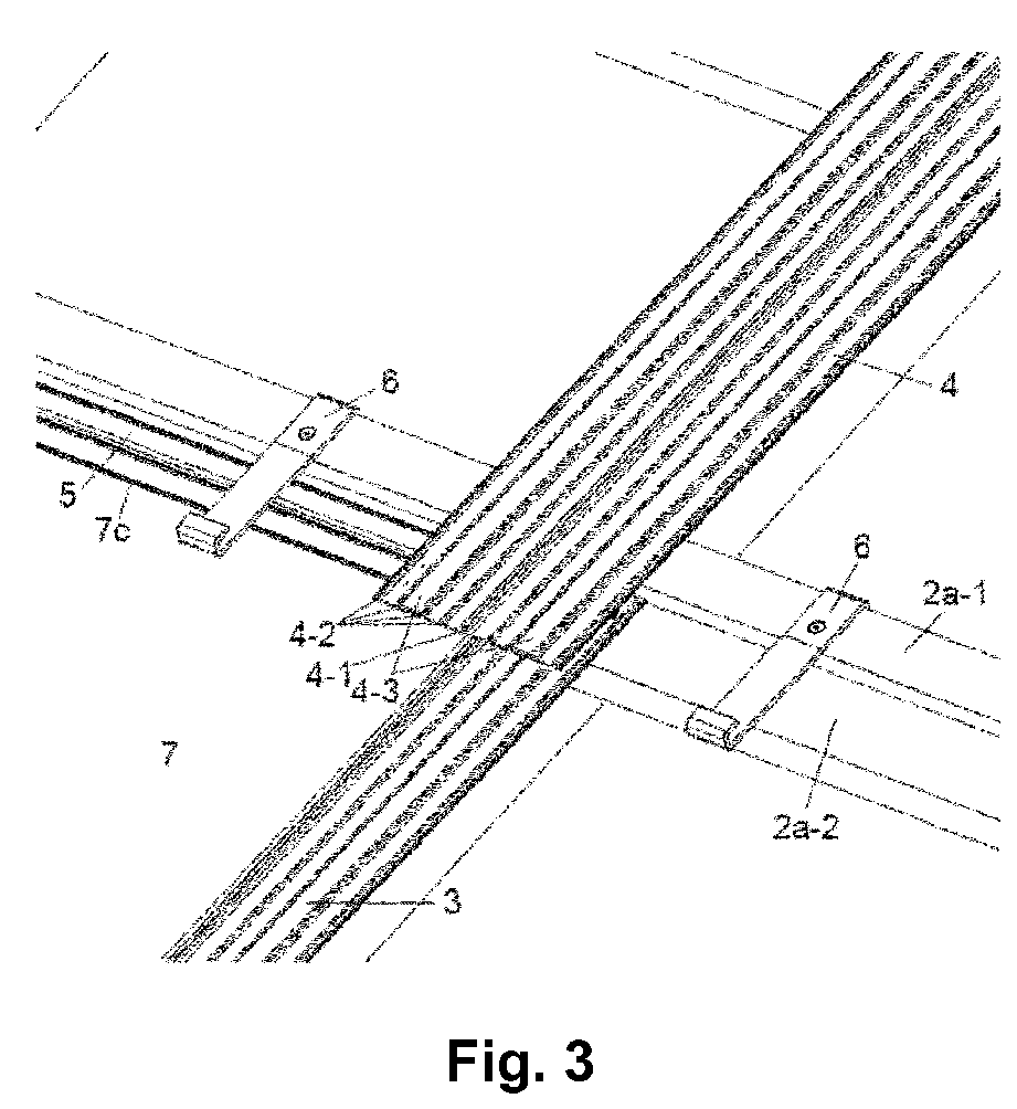
- a comparable effect has the water collection tray (5). Because should some water between the overlapping plates (7) and (8) get it, it is collected in the water sump (5). From there, the water flows to the lateral ends (5a), (5b) of the sump (5), where it reaches the lateral joint profiles (3), (3 '), which are arranged in the direction of water flow.
- each side of the panels is, as a rule, directly or indirectly on the ground and / or by a hard and therefore rigid material such as the joint profiles (3), (3 '), (4) and (4'), resp. the water sump (5), supported.
- the two falling side edges (7a) and (7b) of the plate (7) lie on a part of the laterally adjoining joint profiles (3) and (3 '), the upper side (7c) with the collecting trough (5) attached thereto lies on the lower batten part (2a-2) and the lower side of the plate (7d) is located, for example, on the higher batten part (2a-1) fixed further down and / or on the plate fixing element (s) (6).
- the plate fixing element (s) (6) As a result, surprisingly larger plates can withstand much higher pressure loads, such as snow, even at low angles of inclination.
- the lower joint profiles (3), (3 ') are parallel to the lower plate (7) and the upper joint profiles (4) and (4') are parallel to the upper plate (8th). However, these are not parallel to the substantially laid in the direction of flow slats (2b).
- inventive roof covering (1) and the inventive method surprisingly extremely weatherproof, especially waterproof, building roofs with low inclination angle and large roof load can be created without an additional roof covering such as brick is necessary.
- roof covering according to the invention and the method according to the invention are also suitable for building facades.
- the inventive water collecting trough (5) which preferably at the upper side edge (7c) of the plate (7) with the U-shaped opening of the attachment profile (5-1) can be secured, surprisingly allows the gap between the overlapping plates very small can be held.
- the at least two guide elements (5-3) allow a good fixation of the plate (7) in the U-shaped opening of the attachment profile (5-1).
- the at least two support elements (5-4), which are mounted outside the opening (5-5) of the U-shaped attachment profile (5-1), on the one hand allow a suitable support of the plate (8), which comes to rest thereon. In addition, they form a barrier to the water, that it does not or only very conditionally, into the gutter (5-2), but not beyond flows.
- the gutter (5-2) and the attachment profile (5-1) together form substantially the water sump (5), wherein the gutter (5-2) substantially on the U-shaped attachment profile (5-1) attached and on the Whole length of the slip-on profile (5-1) is arranged.
- the water Via this gutter (5-2), the water, if it penetrates over the upper plate side (7c) which is overlapped by the plate (8), can easily penetrate to the lateral ends (5a), (5b). the collecting trough (5) on the joint profiles (3) and (3 ') drain, which are mounted laterally on the plate (7).
- the EP-A-2 282 141 describes an in-roof solar collector mounting arrangement, comprising a plurality of mounting rail-mounted solar panels, wherein between the Solar modules remain gap-like distance spaces. Below the solar collector arrangement, a channel system is formed, which covers the gap-like spacing spaces and further the gutter system has a liquid-guiding orientation and gradient.
- This in-roof solar collector mounting arrangement is not overlapping and all runoff water flows into the gutter system. As a result, there is a risk that in heavy rain, the water spills over the gutter system and so flows into the ground and causes damage. In addition, it has a large number of interconnecting compounds, which also can easily lead to leaks, especially when the material is moving, for example due to thermal expansion.
- the roof covering (1) according to the invention and the roof covering (1) produced by the method according to the invention are particularly suitable as weatherproof roof covering for pitched roofs of buildings and for covering facades, in particular for building facades.
- the inclination of the roof covering (1) according to the invention and the pitched roof (1) equipped with the roof covering (1) produced according to the invention can be surprisingly low.
- the inclination may have an angle of approximately 6 ° or greater, in particular approximately 8 ° or greater, and very particularly preferably approximately 10 ° or greater, starting from a full angle of 360 °.
- This angle of inclination refers to the angle that one on the Surface (2) laid surface to a horizontal, ie horizontal, surface forms.
- the substrate (2) of the roof covering (1) according to the invention is, for example, the typical substrate which is also used in the construction of a conventional roof covering. Such substrates are known in the art.
- a preferred substrate (2) is in particular a slatted base made of, for example, plastic, metal and / or wood. As a rule, the slatted frame consists of a large number of slats.
- the slatted frame preferably consists essentially of a horizontal, ie. horizontal, laid slats (2a) and slats laid substantially in the direction of flow (2b).
- the distance between the generally parallel laid slats (2a) and (2b) substantially corresponds to the side lengths of the plates to be laid.
- At least one bar is laid between these parallel laid slats so that the laid on it plate (7) rests on the bar.
- the laid plate (7) is not only at the edges, but also in the middle part of the plate.
- one or more printing pads, for example of plastic, for filling in hollows can be attached between the slats.
- a full-surface surface for example made of wood, laid so that the plate (7) comes to lie substantially full surface on it.
- Such slats (2a) may consist of a single, profiled slat, or be assembled and assembled from two different slats, for example, on site.
- the height of the lower lower batten part (2a-2), measured vertically to the ground, may for example be between about 0.1 and 20 cm.
- the upper upper batten part (2a-1) located above the lower batten part (2a-2) is typically about 0.1 to 15 cm higher than the lower lower batten part (2a-2). The distance is advantageously adjusted so that the upper side (7c) of the lower plate (7) with the sump (5) and the joint profile (3), (3 '), which lie on the lower batten part (2a-2) come substantially flush with the upper upper batten part (2a-1).
- joint profiles (3), (3 '), (4) and (4') preferably have the same shape, but according to the invention are not identical to one another.
- a non-limiting embodiment is in Fig. 6 shown.
- the joint profiles (3), (3 '), (4) and (4') of the roof covering according to the invention are fastened to the substrate (2), in particular the slatted frame.
- the manner of attachment is known in the art and can be done for example with screws, nails, clamps and / or gluing.
- the arrangement is preferably carried out so that the water can flow freely in the direction of flow.
- the lower joint profiles (3) and (3 ') delimit the right and left sides (7a) and (7b) of the lower plate (7)
- the upper joint profiles (4) and (4') delimit the right and left sides ( 8a) and (8b) of the upper plate (8) of the roof covering according to the invention.
- the length of the joint profiles (3), (3 '), (4) and (4') substantially corresponds approximately to the side length (7a), (7b) and (8a), (8b) of the plates (7) and (8 ), ie it is preferably about 80 to 120%, in particular about 90 to 110%, and most preferably about 95 to 100% of the plate side length (7a), (7b) and (8a), (8b).
- the joint profiles can be cut to the desired length at the factory or on the construction site.
- typically the number of assembled joint profiles also corresponds to the number of mounted plates, wherein the last row of plates in the direction of flow per plate can still each have an additional joint profile.
- the width of the joint profiles (3), (3 '), (4) and (4') is preferably about 1 to 50 cm, in particular about 5 to 40 cm, and most preferably about 10 to 30 cm.
- the joint profiles (3), (3 '), (4) and (4') preferably have a central web (3-1), (4-1), which after the creation of the roof covering (1) between the plates 7, 8 and 7 ', 8'.
- the central web (3-1), (4-1) at least partially fills the gap between the laterally adjacent plates 7, 8 and 7 ', 8', whereby less water is applied to the joint profiles (3), (3 '), (4) and (4 ') flows.
- the center bar (3-1), (4-1) serves as an assembly aid and channels the water, which makes it run better.
- the joint profiles (3), (3 '), (4) and (4') comprise a base plate, a central web (3-1), (4-1) and at least on each side of the central web (3). 1), (4-1) one, preferably two or more, smaller web (3-2), (4-2).
- the central web of the joint profile (3) resp. (3 ') limits the two adjacent plates (7) and (7').
- the height of the center bar is usually chosen so that it does not come to rest or only a little over the laid panels.
- the smaller bars serve as a lateral boundary, creating a channel in which the water can be removed.
- the smaller webs can also serve as a support for the adjacent plates (7) and (7 ').
- joint profiles (3), (3 '), (4) and (4') can for example also be provided with a sealing strip (3-3), (4-3), on which the plates (7) and (7 '. ) can rest.
- a non-limiting example of a joint profile is in Fig. 6 shown.
- the joint profiles (3), (3 '), (4) and (4') used according to the invention are preferably made of hard material, in particular of hard and rigid material.
- the hard material advantageously has a Shore D hardness of 40 to 100 Shore, preferably 50 to 100 Shore, measured according to DIN EN ISO 868.
- Preferred hard materials are hard plastic, such as polyvinyl chloride (PVC), polymethyl methacrylate (PMMA), Polyethylene (PE) and / or polypropylene (PP), and / or metals such as aluminum, anodized aluminum, copper and / or sheet metal. Aluminum and anodized aluminum are most preferred materials. Due to the hard material of the joint profiles (3), (3 '), (4) and (4'), the plates (7), (8) are laterally additionally stabilized. This allows the plates (7), (8) to withstand increased loads such as snow.
- the plates (7), (8) lie on the joint profiles (3), (3 '), (4) and (4').
- the plates (7), (8) are not covered by the joint profiles (3), (3 '), (4) and (4').
- the joint profiles (3), (3 '), (4) and (4') can be produced in a known manner, for example by milling and / or casting.
- the joint profiles (3), (3 '), (4) and (4') are produced by extrusion, for example by the bar pressing method.
- the two mutually parallel lower joint profiles (3), (3 ') are arranged generally parallel to each other, wherein the distance is selected so that the lower plate (7) on the limited by the central web left side of the joint profile (3) and right side of the joint profile (3 ') can be placed.
- the higher part of the lower joint profile (3) is attached to the lower lower batten part (2a-2) and the lower part of the upper joint profile (4) is fastened to the upper batten part (2a-1).
- the lower joint profile (3 ') and the upper joint profile (4') are attached to the lower joint profile (3) and the upper joint profile (4').
- the upper joint profiles (4), (4 ') overlap the lower joint profiles (3), (3').
- the overlap of the joint profiles (3) and (4), respectively (3 ') and (4') is preferably about 1 cm or more. In general, however, the overlap is not more than about 20 cm, in particular not more than 15 cm.
- the water can pass from the upper joint profile (4) via a small waterfall on the lower joint profile (3) in these preferred embodiments.
- the plate (7) and its laterally adjacent plate (7 ') used they are on the lower joint profiles (3). (3 ') on and the lower part of the upper joint profiles (4). (4 ') comes to lie on the overlapping part of the surface of the lower plates (7) and (7').
- the water, which lead the upper joint profiles (4), (4 ') surprisingly easily and efficiently on the plate surfaces of the plates (7), (7') drain and thus be routed away. This therefore allows the webs of the joint profiles used according to the invention can be lower than other roof coverings, which must dissipate the water over the entire roof length.
- the drip pan (5) of the roof covering (1) according to the invention and the drip pan (5) according to the invention are arranged essentially horizontally, ie, horizontally and parallel to the substrate (2).
- the collecting trough (5) is after installation of the roof covering (1) on the substrate (2), in particular a horizontal, ie horizontal, batten (2a), most preferably at the lower lower batten part (2a-2) on.
- Non-limiting embodiments of the drip pan (5) and the drip pan (5) according to the invention are shown in FIG Fig. 7 and 8th shown.
- the inventive water collecting tray (5) also comprises at least two guide elements (5-3), which protrude into the U-shaped opening (5-5) of the attachment profile (5-1).
- the substantially U-shaped attachment profile (5-1) of the collecting trough (5) according to the invention, and preferably also the collecting trough (5), which can be used in the roof covering, has no holes. This makes it impermeable to water. Thus, no water can get into the roof base and damage is prevented.
- the collecting trough (5) according to the invention and preferably also the collecting trough (5) are made of hard material, in particular of hard material with a Shore D hardness of 40 to 100 Shore, preferably 50 to 100 Shore, measured according to DIN EN ISO 868.
- Preferred hard Materials are hard plastic such as polyvinyl chloride (PVC), polymethyl methacrylate (PMMA), polyethylene (PE) and / or polypropylene (PP), as well as metals such as aluminum, anodized aluminum, copper and / or sheet metal. Aluminum and anodized aluminum are most preferred materials. Due to the hard material of the collecting trough (5), the plates (7), (8) to which the collecting trough (5) is attached, additionally stabilized.
- the drip pan (5) and the drip pan (5) according to the invention can be produced in a known manner, for example with milling and / or casting.
- the collecting trough (5) is produced by extrusion, for example by the bar pressing method.
- the length of the drip pan (5) and the drip pan (5) according to the invention corresponds approximately to the length of the upper plate side (7c) of the plate (7), i. it is about 80 to 120%, preferably about 90 to 110%, in particular about 95 to 100% of the length of the upper plate side (7c).
- the length of the drip pan (5) and the drip pan (5) according to the invention is the length of two or more plate sides (7c) and thus overlaps at least one joint profile.
- the drip pan (5) can in each case over the joint profiles, i. After each plate length, an opening, which is usually a recess, have, can drain through the possibly occurred water on the underlying joint profile.
- the width of the drip pan (5) and the drip pan (5) according to the invention can for example be between 2 cm and 20 cm and also depends on the specific embodiment.
- a particularly preferred embodiment of the drip pan (5) and the drip pan (5) according to the invention comprises a substantially U-shaped plug-on profile (5-1), which is attached to the upper side (7c) of the plate (7). is attached. As a result, the drip pan (5) limits the upper side (7c) of the plate (7).
- the attachment of the substantially U-shaped Aufsteckprofils (5-1) on the upper side (7c) of the plate (7) is preferably carried out by gluing, plugging, clamping, sealing and / or mechanical fastening, for example by means of screws, rivets and / or Nails, with gluing being especially preferred.
- Suitable adhesives are known to the person skilled in the art.
- Nonlimiting examples which may optionally be added with glass fibers include, for example, reactive adhesives, polyester adhesives, multi-component adhesives, polyamide adhesives, epoxy-curing adhesives, acrylate adhesives, and polyurethane adhesives.
- a non-limiting specific embodiments of the inventive water collecting trough (5) is as a cross section in Fig. 7 shown.
- the interpret Fig. 8a to 8i schematically further embodiments.
- the ends (5a) and (5b) of the collecting trough (5) and the collecting trough (5) according to the invention extend from the upper part (3a) of the lower joint profile (3) to the upper part (3'a) of the lower joint profile (3 ') mounted parallel thereto.
- the roof covering (1) according to the invention overlap, i. Cover, the lower parts (4b), (4'b) of the upper joint profiles (4), (4 ') the ends (5a), (5b) of the lower sump (5) wholly or partially. These in turn preferably overlap the upper parts (3a), (3'a) of the lower joint profiles (3), (3 ').
- the lower parts (3b), (3'b) of the lower joint profiles (3), (3 ') also overlap the ends (5a), (5b) of the lower collecting trough (5), which comes under the side (7d) of the plate (7) to lie, in whole or in part.
- recesses (5-7) are provided at the ends (5a) and (5b) of the drip pan (5) and the drip pan (5) according to the invention in the valley of the drip pan, making it easier for the water into the underlying joint profile (FIG. 3), (3 ') can flow.
- the same effect can also be achieved by a collecting trough (5), which does not reach to the ends of the plate side (7), but covers a smaller part of the joint profile than the plate (7).
- the lower part of the substantially U-shaped attachment profile (5-1) of the collecting trough (5) and in particular of the collecting trough (5) according to the invention is shorter than the remaining part of the collecting trough (5), so that it - after the assembly and thereby as part of the roof covering (1) - laterally against the joint profiles (3), (3 ').
- a preferred embodiment of the collecting trough (5) according to the invention has the side facing away from the guide elements (5-4) of the substantially U-shaped attachment profile (5-1) having a tummy (5-6), i. the opening (5-5) of the U-shaped attachment profile is narrower than the diameter in the middle of the U-shape. Due to this bulging, the plate (7), on the upper side (7c) of which the collecting trough (5) is fastened, can surprisingly be fitted particularly well, for example under the overlapping one, i. insert protruding joint profile and / or under already fastened plate fastening elements (6).
- the belly (5-6) is cut off at the lateral ends of the sump (5), and / or at the lower part of the Gutter (5-2) is a recess (5-7) attached.
- a recess (5-7) attached to the side ends of the water from the sump tray (5) in the joint profiles (3), (3 ') can flow more easily.
- the plate (7) lies directly on the joint profile (3), (3 '), resulting in a better support on the ground , As a result, the plate (7) can be exposed to an even greater pressure load. This is of great importance, for example, for roofing in the Alpine region, where, depending on the altitude and location of the site, meter-high snow masses can lie on the roof.
- the plate fastening element (6) also called fastening hook (6), has a fastening device, for example a hook, with which the plates (7) and (8) are fixed.
- a fastening device for example a hook
- it has a device, such as a hole, with which the fastening element (6), for example, on the ground, can be attached.
- the attachment hooks (6) are preferably made of metal, in particular stainless steel, and may optionally be plasticized, i. be covered with plastic. Suitable attachment hooks (6) are known in the art.
- the lower edge (7d), (8d) of the plates (7) and (8) of the roof covering (1) according to the invention is made into at least one, preferably several, plate fastener (6) inserted and thereby secured.
- the plate fastening element (6) is fastened to the substrate, in particular to the slatted frame.
- the plate fastening element (6) forms a unit (9) with the collecting trough (5), the unit (9) being fastened to the substrate, in particular to the slatted frame.
- the collecting trough (5) of the unit (9) after installation partially covers the upper part of the joint profiles (3), (3 ').
- the plate fastening element (6) is attached to at least one of the joint profiles (3), (3 '), (4) and (4').
- the attachment may be to the slats (2b) laid substantially in the direction of flow and / or to the slats substantially horizontally, i. horizontally laid slats (2a).
- the plate fastening element (6) is preferably fastened to the upper, upper batten part (2a-1).
- a plate fastening element (6) is preferably used, which anticipates the function of the higher batten part (2a-1) by means of a suitable shape.
- the panels of the roof covering (1) according to the invention comprise at least one lower panel (7) and one upper panel (8), the upper panel (8) overlapping the lower panel (7).
- the upper plate (8) may be arranged so that the upper plate (8) overlaps only the lower plate (7) or that the plate (8) is staggered so as to overlap a plate (7 ') adjacent to the plate (7) is arranged.
- the plate (7) is - separated only by the central web (3-1) of the joint profile (3), laterally next to the plate (7 ').
- the plate (8) is - separated only by the central web (4-1) of the joint profile (4), laterally adjacent to the adjacent plate (8 ').
- the plates (8) and (8 ') are arranged higher than the plates (7) and their laterally adjacent plate (7').
- the plate (8) overlaps the plate (7) and possibly also the plate (7 '). The same applies to the plate (8 ').
- the overlap of the plates (7), (7 ') by the plates (8), (8') is preferably about 1 cm or more.
- the overlap may for example be up to about 20 cm, in particular up to about 15 cm. However, this is not a requirement for obtaining a watertight arrangement.
- the types and size of the plates (7) and (8) of the roof covering (1) according to the invention surprisingly have no essential limits.
- the panels (7) and (8) may include a photovoltaic panel, a solar panel, a solar panel, a solar collector for producing hot and / or hot water, a building panel, a wooden panel, a plywood panel, a cement fiber panel, a metal panel, a Be plastic plate, a clay plate, a mineral plate, a glass plate and / or a stone slab.
- the metal is preferably substantially aluminum, copper, sheet metal, and / or iron, which may also be coated.
- the plates (7) and (8) can all be the same type of plate. But it is also possible to use different plates, for example, both one or more photovoltaic panels and one or more solar panels for the production of hot and / or hot water. In addition, it is also possible to use in addition to photovoltaic panels and / or solar panels in addition, for example, cement fiber boards. This is particularly advantageous if the entire roof surface can not or does not want to be covered with the available photovoltaic panels and / or solar panels. Thus, for example, cement fiber boards in this embodiment are preferably used at the edge zones of the roof covering (1). Such plates may then be simply ground to the desired mass, i. to the mass required due to the roof dimensions.
- the size of the plates (7), (8) depends essentially on the masses customary in commerce. Due to the handling when laying the length of the plates (7), (8) is preferably between about 60 cm and about 300 cm, the width between about 40 cm and about 130 cm and the height, respectively. Thickness, the plates is about 2 mm to about 10 cm or more.
- the inventive roof covering (1) and the inventive method are - at least the largest part - the falling side edges (7a), (7b) of the plate (7) substantially on a part of the joint profiles (3) and (3 ') and the falling side edges (8a), (8b) of the plate (8) lie - at least for the most part - essentially on a part of the joint profiles (4) and (4 ').
- the sloping side edges (7a), (7b) of the plate (7) laterally through the joint profiles (3) and (3 ') and the sloping side edges (8a), (8b) of the plate (8) laterally through the joint profiles ( 4) and (4 ') limited.
- the roof covering (1) according to the invention and the method according to the invention comprise a water collecting trough (5) and / or a seal (10).
- Suitable seals are known in the art. Non-limiting examples include polyurethane gaskets, acrylate gaskets, nitrile and NBR gaskets, rubber gaskets, EPDM gaskets, and gaskets made from multi-component adhesives, adhesives and / or sealants, as well as neoprene tape, EPDM tape, and silicone tape.
- the seal (10), if used, is placed between the plates (7) and (8) to prevent ingress of water.
- the gasket (10) is mounted substantially along the entire side to achieve a complete seal.
- a seal (10) for example, a silicone gasket, in particular a silicone joint seal can be used.
- a silicone gasket in particular a silicone joint seal
- Such seals (10) are known in the art.
- a seal (10) for example, between the plates (7), (8) and a foam adhesive, for example based on polyurethane, are attached.
- seals (10) for example, compressible foam and / or soft plastic such as rubber can be used.
- Such seals (10), which are known in the art, are preferably mounted on the upper side of the plate (7) in the region of the upper side (7c) and / or on the underside of the plate (8) in the region of the lower side (8d) . for example, by gluing.
- the height resp. Thickness of the seal is usually chosen so that the seal touches both plates (7) and (8), preferably even slightly compressed after assembly of the plates.
- the roof attachment (1) is limited by side finishes. Suitable side finishes are known to those skilled in the art.
- the lower side (7d), (7'd) of the bottom plates (7), (7 ') is advantageously not limited, so that the water can flow into a roof canopy or a gutter.
- the upper side (8c), (8'c) of the upper plates (8), (8 ') may be bounded by known ridge profiles. Such ridge profiles are known to the person skilled in the art.
- the lateral sides (7'a), (8'a) and (7b), (8b) of the plates (7), (7 '), (8) and (8') can in a preferred embodiment by side connection profiles (11 ) and (11 ') are limited.
- the side connection profiles (11) and (11 ') can be made of the same materials and processes as the joint profiles (3), (3'), (4) and (4 ').
- a non-limiting, but preferred embodiment of a side connection profile (11) is in Fig. 9 shown and described below.
- the side connection profile (11 ') is advantageously identical, but mirror-inverted to the side connection profile (11).
- the method according to the invention allows the upper plate (8) to be laid first in a simple manner and then the upper side (7c) of the lower plate (7) under the lower side (8d) of the upper plate (8 ) is pushed. Subsequently, advantageously, the plate (7), which rests preferably on the joint profiles (3) and (3 '), simply on the joint profiles (3) and (3') down into the plate or the mounting elements (6) pushed between the lower areas, ie Parts, the joint profiles (3b) and (3'b) are attached.
- This method of operation has the great advantage that the craftsmen can move on the ground (2) and thus on the slatted frame from top to bottom. There is thus no risk of damage to the plates, as is the case when first the lower plates (7) and subsequently the upper plates (8) are laid.
- a water sump (5) is attached to the upper side (7c) of the plate (7), which discharges penetrating water through the joint profiles (3), (3 ').
- the attachment usually takes place before the plate (7) is mounted. This embodiment is particularly preferred when the collecting trough (5) according to the invention is used.
- a seal (10) is placed between the plates (7) and (8) to prevent ingress of water.
- the gasket (10) is mounted substantially along the entire side to achieve a complete seal.
- the inventive method is also based on Fig. 1 to Fig. 5 described in more detail.
Landscapes
- Engineering & Computer Science (AREA)
- Chemical & Material Sciences (AREA)
- Life Sciences & Earth Sciences (AREA)
- Sustainable Development (AREA)
- Sustainable Energy (AREA)
- Thermal Sciences (AREA)
- Physics & Mathematics (AREA)
- Combustion & Propulsion (AREA)
- Mechanical Engineering (AREA)
- General Engineering & Computer Science (AREA)
- Architecture (AREA)
- Civil Engineering (AREA)
- Structural Engineering (AREA)
- Roof Covering Using Slabs Or Stiff Sheets (AREA)
Abstract
Die vorliegende Erfindung betrifft eine Dachbedeckung (1) umfassend einen Untergrund (2), insbesondere Lattenrost, zwei seitliche untere Fugenprofile (3), (3') und zwei obere seitliche Fugenprofile (4), (4') die in Fliessrichtung übereinander angebracht sind, gegebenenfalls eine Wasser Auffangwanne (5) und/oder eine Dichtung (10), ein Plattenbefestigungselement (6), eine untere Platte (7) und eine obere Platte (8), wobei Platte (8) die Platte (7) überlappt und die fallenden Seitenränder (7a), (7b) der Platte (7) im Wesentlichen auf den Fugenprofilen (3), (3') und die fallenden Seitenränder (8a), (8b) der Platte (8) im Wesentlichen auf den Fugenprofilen (4), (4') liegen.The present invention relates to a roof covering (1) comprising a substrate (2), in particular slatted frame, two lateral lower joint profiles (3), (3 ') and two upper lateral joint profiles (4), (4') which are mounted one above the other in the direction of flow optionally a water sump (5) and / or a seal (10), a plate fastener (6), a lower plate (7) and an upper plate (8), wherein plate (8) overlaps the plate (7) and the falling side edges (7a), (7b) of the plate (7) substantially on the joint profiles (3), (3 ') and the falling side edges (8a), (8b) of the plate (8) substantially on the joint profiles (4 ), (4 ').
Beansprucht wird auch ein Verfahren zum Montieren der Dachbedeckung (1) sowie die Verwendung der Dachbedeckung (1) auf Dächern und/oder Fassaden von Gebäuden, insbesondere zur Nutzung der Sonnenenergie mit Photovoltaik Panel, Solarpanel, Solarmodulen und/oder Sonnenkollektoren zur Erzeugung von Elektrizität, Warm- und/oder Heisswasser.Also claimed is a method for mounting the roof covering (1) and the use of the roof covering (1) on roofs and / or facades of buildings, in particular for the use of solar energy with photovoltaic panels, solar panels, solar modules and / or solar panels for generating electricity, Hot and / or hot water.
Zudem betrifft die Erfindung eine Wasser Auffangwanne (5) aus hartem Material, bevorzugt aus Metall oder Hart-Kunststoff, umfassend ein im Wesentlichen U-förmiges Aufsteckprofil (5-1), eine Auffangrinne (5-2) ohne Löcher, mindestens zwei Führungselemente (5-3), die in die U-förmige Öffnung des Aufsteckprofils (5-1) hineinragen, und mindestens zwei Auflageelemente (5-4), die ausserhalb der Öffnung (5-5) des U-förmigen Aufsteckprofils (5-1) angebracht sind und im Wesentlichen mit einer geraden Linie miteinander verbunden werden können.
Description
Die Erfindung betrifft eine Dachbedeckung, ein Verfahren zum Montieren der Dachbedeckung, eine Wasser Auffangwanne sowie die Verwendung der Dachbedeckung insbesondere zur Nutzung der Sonnenenergie mittels Photovoltaik Panel, Solarpanel, Solarmodulen und/oder Sonnenkollektoren.The invention relates to a roof covering, a method for mounting the roof covering, a water collecting tray and the use of the roof covering in particular for the use of solar energy by means of a photovoltaic panel, solar panel, solar modules and / or solar panels.
Die Gewinnung von Energie aus Sonnenlicht, auch Sonnenenergie oder Solarenergie genannt, hat in neuerer Zeit an Bedeutung gewonnen und wird in Zukunft noch wichtiger. Deshalb werden vermehrt Platten wie beispielsweise Photovoltaik Panel, Solarpanel, Solarmodule und Sonnenkollektoren zur Erzeugung von Warm- und/oder Heisswasser vor allem auf Dächern und Fassaden von Gebäuden und Infrastrukturbauten montiert.The extraction of energy from sunlight, also called solar or solar energy, has gained in importance in recent times and will become even more important in the future. For this reason, panels such as photovoltaic panels, solar panels, solar modules and solar collectors for the production of hot and / or hot water are increasingly being installed on roofs and facades of buildings and infrastructure buildings.
Bei bestehenden Dächern werden üblicherweise solche Panels, Module oder Kollektoren auf das beispielsweise mit Ziegeln bedeckte Dach montiert.In existing roofs usually such panels, modules or collectors are mounted on the example, tiled roof.
Bei Neubauten, Teil- oder Total-Renovationen ist es jedoch vorteilhaft, wenn solche Panels, Module oder Kollektoren direkt die schützende Dachbedeckung, d.h. eine Indach-Bedeckung, bilden. So muss nicht zuerst das Dach aufwändig mit beispielsweise Ziegeln bedeckt werden um in einem nachfolgenden Schritt die Panels, Module oder Kollektoren zu befestigen.However, in new, partial or total renovation, it is advantageous if such panels, modules or collectors directly cover the protective roof covering, i. an in-roof covering. Thus, it is not necessary first to cover the roof with bricks, for example, in order to fasten the panels, modules or collectors in a subsequent step.
Um den hohen Anforderungen einer Dachbedeckung zu genügen, ist es jedoch essentiell, dass unter anderem keinerlei Wasser in den Dachuntergrund eindringt, was zu Schäden führen kann. Zudem muss die Dachbedeckung auch so konstruiert sein, dass sie Drucklasten wie beispielsweise Schnee, standhalten kann, ohne beschädigt zu werden.In order to meet the high demands of a roof covering, however, it is essential that, inter alia, no water penetrates into the roof surface, which can lead to damage. In addition, the roof covering must also be designed so that it can withstand pressure loads such as snow, without being damaged.
Bei herkömmlichen Dachbedeckungen werden diese Anforderungen beispielsweise mit kleinformatigen Ziegeln erreicht, die auf einem engmaschigen Lattenrost befestigt sind.In conventional roofing these requirements are achieved, for example, with small-sized bricks, which are mounted on a close-meshed slatted frame.
Bei den zur Energiegewinnung notwendigen Panels, Modulen und Kollektoren gestaltet sich die Aufgabe jedoch schwieriger, da diese wesentlich grössere Abmessungen aufweisen als kleinformatige Ziegel. Deshalb wird bei der Verlegung der Panels, Module und Kollektoren darauf geachtet, dass die Dachneigung entsprechend gross ist, beispielsweise einen Winkel von mindestens 20° zu einer horizontalen, d.h. waagrechten, Fläche aufweist. Zudem ist es wichtig, dass die Panels, Module und Kollektoren zum Teil um 15 cm oder mehr überlappen, d.h. überdecken. Allerdings wird dadurch ein Teil der teuren Panels, Module und Kollektoren überdeckt, wodurch der Wirkungsgrad je Panel, Modul und Kollektor reduziert wird. Zusätzlich schränkt sich der Anwendungsbereich auf Dächer ein, die einen entsprechend hohen Neigungswinkel aufweisen.In the need for energy panels, modules and collectors, the task is more difficult because they have much larger dimensions than small-sized bricks. Therefore, when laying the panels, modules and collectors, care must be taken to ensure that the roof pitch is correspondingly large, for example an angle of at least 20 ° to a horizontal, i. horizontal, surface. In addition, it is important that the panels, modules and collectors overlap in part by 15 cm or more, i. cover. However, this covers some of the expensive panels, modules and collectors, reducing the efficiency per panel, module and collector. In addition, the scope of application is limited to roofs that have a correspondingly high angle of inclination.
Die
Die
Die
Die
Daher stellt sich die Aufgabe, eine wetterfeste, insbesondere eine wasserfeste und wasserdichte, Dachbedeckung in Form einer Indach-Bedeckung, beispielsweise zur Sonnenenergiegewinnung mittels Panels, Modulen und/oder Kollektoren, bereit zu stellen, die auch bei Dächern mit geringer Neigung eingesetzt und hohen Belastungen ausgesetzt werden kann und trotzdem nur eine geringe Überlappung der jeweiligen Panels, Modulen und/oder Kollektoren benötigt.Therefore, the task of a weatherproof, especially a waterproof and waterproof, roof covering in the form of an in-roof covering, for example, to provide solar energy by means of panels, modules and / or collectors, to provide that also used for roofs with low inclination and high loads can be exposed and still requires only a slight overlap of the respective panels, modules and / or collectors.
Diese Aufgabe konnte überraschenderweise gelöst werden mit einer Dachbedeckung (1) umfassend
- einen Untergrund (2), insbesondere Lattenrost,
- mindestens zwei seitliche untere Fugenprofile (3), (3') und zwei obere seitliche Fugenprofile (4), (4'), wobei die Fugenprofile (3), (4) resp. (3'), (4') in Fliessrichtung übereinander angebracht sind und am Untergrund (2) befestigt sind,
- gegebenenfalls i) eine Wasser Auffangwanne (5), wobei die Auffangwanne (5) im Wesentlichen horizontal, d.h. waagrecht und parallel zum Untergrund (2) angeordnet ist, und/oder ii) eine Dichtung (10), wobei die Dichtung (10) zwischen den überlappenden Bereichen der unteren Platte (7) und der oberen Platte (8) im Wesentlichen horizontal, d.h. waagrecht, zum Untergrund (2) angeordnet ist,
- pro Platte mindestens ein Plattenbefestigungselement (6),
- mindestens eine untere Platte (7) und eine obere Platte (8), wobei die untere Seite (7d) der Platte (7) und die untere Seite (8d) der Platte (8) durch mindestens ein Plattenbefestigungselement (6) pro Platte gehalten werden,
- a substrate (2), in particular slatted frame,
- at least two lateral lower joint profiles (3), (3 ') and two upper lateral joint profiles (4), (4'), wherein the joint profiles (3), (4) resp. (3 '), (4') are mounted one above the other in the direction of flow and are fastened to the substrate (2),
- optionally i) a water sump (5), the sump (5) is arranged substantially horizontally, ie horizontally and parallel to the substrate (2), and / or ii) a seal (10), wherein the seal (10) between the overlapping areas of the lower plate (7) and the upper plate (8) is arranged substantially horizontally, ie horizontally, to the substrate (2),
- at least one plate fastening element (6) per plate,
- at least one lower plate (7) and one upper plate (8), the lower side (7d) of the plate (7) and the lower side (8d) of the Plate (8) are held by at least one plate fastener (6) per plate,
Beansprucht wird auch ein Verfahren zum Montieren der erfindungsgemässen Dachbedeckung (1) mit einer unteren Platte (7) und einer die Platte (7) überlappenden oberen Platte (8), umfassend die folgenden Schritte:
- i) Befestigen von unteren linken und rechten Fugenprofilen (3), (3') und oberen linken und rechten Fugenprofilen (4), (4') am Untergrund (2), insbesondere am Lattenrost,
- ii) Befestigen von Plattenbefestigungselementen (6) am Untergrund (2), insbesondere Lattenrost, in im Wesentlichen waagrechter Richtung, zwischen den unteren Bereichen der linken und rechten Fugenprofile (3b), (3'b) und zwischen den unteren Bereichen der linken und rechten Fugenprofile (4b), (4'b),
- iii) Legen der Seitenränder (8a), (8b) der oberen Platte (8) im Wesentlichen auf die linken und rechten oberen Fugenprofile (4), (4') und Einfügen der unteren Seite (8d) der Platte (8) in die zwischen den unteren Bereichen der linken und rechten Fugenprofile (4b), (4'b) angebrachten Plattenbefestigungselemente (6), und
- iv) Legen der Seitenränder (7a), (7b) der unteren Platte (7) im Wesentlichen auf die linken und rechten unteren Fugenprofile (3), (3') und Einfügen der unteren Seite (7d) der Platte (7) in die zwischen den unteren Bereichen der linken und rechten Fugenprofile (3b), (3'b) angebrachten Plattenbefestigungselemente (6),
- i) fastening lower left and right joint profiles (3), (3 ') and upper left and right joint profiles (4), (4') on the substrate (2), in particular on the slatted base,
- ii) fixing plate fixing elements (6) to the substrate (2), in particular slatted, in a substantially horizontal direction, between the lower regions of the left and right joint profiles (3b), (3'b) and between the lower regions of the left and right Joint profiles (4b), (4'b),
- iii) laying the side edges (8a), (8b) of the upper plate (8) substantially on the left and right upper joint profiles (4), (4 ') and inserting the lower side (8d) of the plate (8) in the between the lower portions of the left and right joint profiles (4b), (4'b) mounted plate fasteners (6), and
- iv) laying the side edges (7a), (7b) of the lower plate (7) substantially on the left and right lower joint profiles (3), (3 ') and inserting the lower side (7d) of the plate (7) in the between the lower regions of the left and right joint profiles (3b), (3'b) mounted plate fastening elements (6),
Gegenstand der Erfindung ist zudem auch die Verwendung der erfindungsgemässen Dachbedeckung (1) und der nach dem erfindungsgemässen Verfahren hergestellten Dachbedeckung (1) auf Dächern und/oder Fassaden von Gebäuden, d.h. auf Gebäudedächern und an Gebäudefassaden, insbesondere zur Nutzung der Sonnenenergie mittels Photovoltaik Panel, Solarpanel, Solarmodulen und/oder Sonnenkollektoren zur Erzeugung von Elektrizität, Warm- und/oder Heisswasser.The invention also provides for the use of the roof covering (1) according to the invention and the roof covering (1) produced by the method according to the invention on roofs and / or facades of buildings, i. on building roofs and on building facades, in particular for the use of solar energy by means of a photovoltaic panel, solar panel, solar modules and / or solar panels for generating electricity, hot and / or hot water.
Die vorliegende erfindungsgemässe Dachbedeckung (1), das erfindungsgemässe Verfahren zur Herstellung der Dachbedeckung (1) und die erfindungsgemässe Verwendung besitzen viele Vorteile. So wurde überraschend gefunden, dass selbst bei einem sehr geringen Neigungswinkel des Daches von lediglich etwa 6° zur horizontalen Fläche, d.h. waagrechten und somit rechtwinklig zur Lotrichtung, nur eine sehr geringe Überlappung der Platten, d.h. beispielsweise der Panels, Modulen und/oder Kollektoren, von beispielsweise einem oder wenigen Zentimetern notwendig ist, um die notwendige Wetter- und insbesondere Wasserfestigkeit der Dachbedeckung (1) zu gewährleisten. Dadurch betrifft die Überlappung nur die Randzone der Panels, Modulen und/oder Kollektoren und nicht die zur Energiegewinnung notwendigen Bereiche, wodurch keine Einschränkung in der Energieeffizienz der Dachbedeckung (1) entsteht. Zudem erlaubt die erfindungsgemässe Dachbedeckung (1), das erfindungsgemässe Verfahren sowie die erfindungsgemässe Verwendung die Montage von Platten ohne dass diese - beispielsweise durch Schrauben - am Untergrund befestigt werden. Dies ist insbesondere bei Platten aus Glas, wie beispielsweise Photovoltaik-Platten, vorteilhaft.The present inventive roof covering (1), the inventive method for producing the roof covering (1) and the inventive use have many advantages. Thus, it was surprisingly found that even with a very small angle of inclination of the roof of only about 6 ° to the horizontal surface, ie horizontal and thus perpendicular to the perpendicular direction, only a very small overlap of the plates, ie for example the panels, modules and / or collectors, For example, one or a few centimeters is necessary to ensure the necessary weather and in particular water resistance of the roof covering (1). As a result, the overlap concerns only the edge zone of the panels, modules and / or collectors and not the areas required for energy production, whereby no restriction in the energy efficiency of the roof covering (1) arises. In addition, the roof covering (1) according to the invention, the method according to the invention and the use according to the invention permit the assembly of panels without that these - for example by screws - are attached to the substrate. This is particularly advantageous for glass panels, such as photovoltaic panels.
Überraschenderweise wurde gefunden, dass durch die erfindungsgemässe Dachbedeckung (1) und das erfindungsgemässe Verfahren zur Herstellung der Dachbedeckung (1) das Wasser auch bei grossen Niederschlagsmengen und heftigen Winden über die Oberfläche der Platten abgeführt wird und nicht in die Dachunterkonstruktion gelangt. Durch die Dichtung (10) wird verhindert, dass Wasser zwischen die sich überlappenden Platten (7) und (8) gelangt. Einen vergleichbaren Effekt weist die Wasser Auffangwanne (5) auf. Denn sollte etwas Wasser zwischen die sich überlappenden Platten (7) und (8) gelangen, wird es in der Wasser Auffangwanne (5) aufgefangen. Von dort fliesst das Wasser zu den seitlichen Enden (5a), (5b) der Auffangwanne (5), wo es auf die seitlichen Fugenprofile (3), (3') gelangt, die in Fliessrichtung des Wassers angeordnet sind. Dadurch fliesst das Wasser der Schwerkraft folgend, seitlich der Platte (7) nach unten. Am Ende der Platte, und somit in der Regel auch am Ende der seitlichen Fugenprofile, fliesst dann das Wasser aufgrund der Überlappung der Platten (7), (8) durch die oberen Fugenprofile auf die darunter liegende Platte. Somit wird das auf den Fugenprofilen abfliessende Wasser nach jeder Plattenlänge wieder neu über die Oberfläche der Dachbedeckung (1) abgeführt. Dadurch werden die Auffangwanne (5) wie auch die Fugenprofile (3), (3'), (4) und (4') nicht mit Wasser überlastet, sondern dies wird nach jeder Platte neu über die Oberfläche vollständig abgeführt. Durch diese erfindungsgemässe Dachbedeckung tritt somit kein Wasser in den Untergrund ein und dieser bleibt trocken.Surprisingly, it has been found that by the roof covering according to the invention (1) and the method according to the invention for producing the roof covering (1), the water is discharged even over large amounts of precipitation and violent winds over the surface of the panels and does not reach the roof substructure. The seal (10) prevents water from getting between the overlapping plates (7) and (8). A comparable effect has the water collection tray (5). Because should some water between the overlapping plates (7) and (8) get it, it is collected in the water sump (5). From there, the water flows to the lateral ends (5a), (5b) of the sump (5), where it reaches the lateral joint profiles (3), (3 '), which are arranged in the direction of water flow. As a result, the water flows according to gravity, the side of the plate (7) down. At the end of the plate, and thus usually at the end of the lateral joint profiles, then the water flows due to the overlap of the plates (7), (8) through the upper joint profiles on the underlying plate. Thus, the effluent on the joint profiles water is discharged again after each plate length on the surface of the roof covering (1). As a result, the drip pan (5) as well as the joint profiles (3), (3 '), (4) and (4') are not overloaded with water, but this is completely removed after each plate over the surface completely. As a result of this roof covering according to the invention, therefore, no water enters the substrate and it remains dry.
Durch die erfindungsgemässe Dachbedeckung (1) und das erfindungsgemässe Verfahren zur Herstellung der Dachbedeckung (1) liegt zudem in der Regel jede Seite der Platten direkt oder indirekt auf dem Untergrund auf und/oder werden durch ein hartes und somit starres Material wie die Fugenprofile (3), (3'), (4) und (4'), resp. die Wasser Auffangwanne (5), gestützt. Die beiden fallenden Seitenränder (7a) und (7b) der Platte (7) liegen auf einem Teil der seitlich anliegenden Fugenprofile (3) und (3'), die obere Seite (7c) mit der daran befestigten Auffangwanne (5) liegt auf dem unteren Lattenteil (2a-2) und die untere Seite der Platte (7d) liegt beispielsweise auf dem weiter unten befestigten höheren Lattenteil (2a-1) und/oder auf dem oder den Plattenbefestigungselementen (6). Dadurch können überraschenderweise grössere Platten auch bei geringem Neigungswinkel wesentlich höheren Drucklasten, wie beispielsweise Schnee, standhalten.In addition, as a result of the roof covering (1) according to the invention and the method according to the invention for producing the roof covering (1), each side of the panels is, as a rule, directly or indirectly on the ground and / or by a hard and therefore rigid material such as the joint profiles (3), (3 '), (4) and (4'), resp. the water sump (5), supported. The two falling side edges (7a) and (7b) of the plate (7) lie on a part of the laterally adjoining joint profiles (3) and (3 '), the upper side (7c) with the collecting trough (5) attached thereto lies on the lower batten part (2a-2) and the lower side of the plate (7d) is located, for example, on the higher batten part (2a-1) fixed further down and / or on the plate fixing element (s) (6). As a result, surprisingly larger plates can withstand much higher pressure loads, such as snow, even at low angles of inclination.
Bei der erfindungsgemässen Dachbedeckung (1) und der nach dem erfindungsgemässen Verfahren hergestellten Verfahren sind die unteren Fugenprofile (3), (3') parallel zur unteren Platte (7) und die oberen Fugenprofile (4) und (4') parallel zur oberen Platte (8). Diese sind jedoch nicht parallel zu den im Wesentlichen in Fliessrichtung verlegten Latten (2b).In the roof covering (1) according to the invention and the method produced by the method according to the invention, the lower joint profiles (3), (3 ') are parallel to the lower plate (7) and the upper joint profiles (4) and (4') are parallel to the upper plate (8th). However, these are not parallel to the substantially laid in the direction of flow slats (2b).
Somit können mit der erfindungsgemässen Dachbedeckung (1) und dem erfindungsgemässen Verfahren überraschenderweise äusserst wetterfeste, insbesondere wasserfeste, Gebäudedächer mit niedrigem Neigungswinkel und grosser Dachlast erstellt werden, ohne dass eine zusätzliche Dachbedeckung wie Ziegel notwendig ist. Zudem eignet sich die erfindungsgemässe Dachbedeckung und das erfindungsgemässe Verfahren auch gut für Gebäudefassaden.Thus, with the inventive roof covering (1) and the inventive method surprisingly extremely weatherproof, especially waterproof, building roofs with low inclination angle and large roof load can be created without an additional roof covering such as brick is necessary. In addition, the roof covering according to the invention and the method according to the invention are also suitable for building facades.
Gegenstand der Erfindung ist auch eine Wasser Auffangwanne (5), umfassend
- ein im Wesentlichen U-förmiges Aufsteckprofil (5-1),
- eine Auffangrinne (5-2) ohne Löcher,
- mindestens zwei Führungselemente (5-3), die in die U-förmige Öffnung (5-5) des Aufsteckprofils (5-1) hineinragen, und - mindestens zwei Auflageelemente (5-4), die ausserhalb der Öffnung (5-5) des U-förmigen Aufsteckprofils (5-1) angebracht sind und im Wesentlichen mit einer geraden Linie miteinander verbunden werden können,
- a substantially U-shaped attachment profile (5-1),
- a gutter (5-2) without holes,
- at least two guide elements (5-3) which project into the U-shaped opening (5-5) of the attachment profile (5-1), and - At least two support elements (5-4), which are outside the opening (5-5) of the U-shaped attachment profile (5-1) are mounted and can be connected to each other with a straight line,
Die erfindungsgemässe Wasser Auffangwanne (5), welche bevorzugt am oberen Seitenrand (7c) der Platte (7) mit der U-förmige Öffnung des Aufsteckprofils (5-1) befestigt werden kann, ermöglicht überraschend, dass der Zwischenraum zwischen den überlappenden Platten sehr klein gehalten werden kann. Die mindestens zwei Führungselemente (5-3) ermöglichen eine gute Fixierung der Platte (7) in der U-förmigen Öffnung des Aufsteckprofils (5-1). Die mindestens zwei Auflageelemente (5-4), die ausserhalb der Öffnung (5-5) des U-förmigen Aufsteckprofils (5-1) angebracht sind, erlauben einerseits eine geeignete Auflage der Platte (8), die darauf zu liegen kommt. Zudem bilden sie eine Barriere für das Wasser, dass dieses nicht oder nur sehr bedingt, in die Auffangrinne (5-2), aber nicht darüber hinaus, fliesst. Die Auffangrinne (5-2) und das Aufsteckprofil (5-1) bilden zusammen im Wesentlichen die Wasser Auffangwanne (5), wobei die Auffangrinne (5-2) im Wesentlichen am U-förmigen Aufsteckprofil (5-1) befestigt und über die ganze Länge des Aufsteckprofils (5-1) angeordnet ist. Über diese Auffangrinne (5-2) kann das Wasser - sollte es über die obere Plattenseite (7c), die durch die Platte (8) überlappt wird, durchdringen - auf einfache Art und Weise zu den seitlichen Enden (5a), (5b) der Auffangwanne (5) auf die Fugenprofile (3) und (3') abfliessen, die seitlich an der Platte (7) angebracht sind.The inventive water collecting trough (5), which preferably at the upper side edge (7c) of the plate (7) with the U-shaped opening of the attachment profile (5-1) can be secured, surprisingly allows the gap between the overlapping plates very small can be held. The at least two guide elements (5-3) allow a good fixation of the plate (7) in the U-shaped opening of the attachment profile (5-1). The at least two support elements (5-4), which are mounted outside the opening (5-5) of the U-shaped attachment profile (5-1), on the one hand allow a suitable support of the plate (8), which comes to rest thereon. In addition, they form a barrier to the water, that it does not or only very conditionally, into the gutter (5-2), but not beyond flows. The gutter (5-2) and the attachment profile (5-1) together form substantially the water sump (5), wherein the gutter (5-2) substantially on the U-shaped attachment profile (5-1) attached and on the Whole length of the slip-on profile (5-1) is arranged. Via this gutter (5-2), the water, if it penetrates over the upper plate side (7c) which is overlapped by the plate (8), can easily penetrate to the lateral ends (5a), (5b). the collecting trough (5) on the joint profiles (3) and (3 ') drain, which are mounted laterally on the plate (7).
Es wird bemerkt, dass die
Die erfindungsgemässe Dachbedeckung (1) und die durch das erfindungsgemässe Verfahren hergestellte Dachabdeckung (1) eignen sich insbesondere als wetterfeste Dachbedeckung für Schrägdächer von Gebäuden und für Bedeckung von Fassaden, insbesondere für Gebäudefassaden.The roof covering (1) according to the invention and the roof covering (1) produced by the method according to the invention are particularly suitable as weatherproof roof covering for pitched roofs of buildings and for covering facades, in particular for building facades.
Es wurde überraschend gefunden, dass die Neigung der erfindungsgemässen Dachbedeckung (1) und der mit dem erfindungsgemässen Verfahren hergestellten Dachbedeckung (1) ausgestatteten Schrägdachs erstaunlich niedrig sein kann. So kann die Neigung auch bei sehr geringer Überlappung von beispielsweise 1cm einen Winkel von etwa 6° oder grösser, insbesondere von etwa 8° oder grösser, und ganz besonders bevorzugt von etwa 10° oder grösser, aufweisen, ausgehend von einem Vollwinkel von 360°. Dieser Neigungswinkel bezieht sich auf den Winkel, den eine auf den Untergrund (2) gelegte Fläche zu einer horizontalen, d.h. waagrechten, Fläche bildet.It has surprisingly been found that the inclination of the roof covering (1) according to the invention and the pitched roof (1) equipped with the roof covering (1) produced according to the invention can be surprisingly low. Thus, even with a very small overlap of, for example, 1 cm, the inclination may have an angle of approximately 6 ° or greater, in particular approximately 8 ° or greater, and very particularly preferably approximately 10 ° or greater, starting from a full angle of 360 °. This angle of inclination refers to the angle that one on the Surface (2) laid surface to a horizontal, ie horizontal, surface forms.
Der Untergrund (2) der erfindungsgemässen Dachbedeckung (1) ist beispielsweise der typische Untergrund, welcher auch beim Bau einer üblichen Dachbedeckung verwendet wird. Solche Untergründe sind dem Fachmann bekannt. Ein bevorzugter Untergrund (2) ist insbesondere ein Lattenrost aus beispielsweise Kunststoff, Metall und/oder Holz. In der Regel besteht der Lattenrost aus einer Vielzahl von Latten.The substrate (2) of the roof covering (1) according to the invention is, for example, the typical substrate which is also used in the construction of a conventional roof covering. Such substrates are known in the art. A preferred substrate (2) is in particular a slatted base made of, for example, plastic, metal and / or wood. As a rule, the slatted frame consists of a large number of slats.
Wird als Untergrund (2) ein Lattenrost verwendet, besteht der Lattenrost bevorzugt aus im Wesentlichen horizontal, d.h. waagrecht, verlegten Latten (2a) und im Wesentlichen in Fliessrichtung verlegten Latten (2b).If a slatted base is used as the base (2), the slatted frame preferably consists essentially of a horizontal, ie. horizontal, laid slats (2a) and slats laid substantially in the direction of flow (2b).
In einer Ausführungsform entspricht der Abstand der in der Regel parallel verlegten Latten (2a) und (2b) im Wesentlichen den Seitenlängen der zu verlegenden Platten.In one embodiment, the distance between the generally parallel laid slats (2a) and (2b) substantially corresponds to the side lengths of the plates to be laid.
In einer anderen Ausführungsform wird zwischen diesen parallel verlegten Latten zusätzlich mindestens eine Latte so verlegt, dass die darauf verlegte Platte (7) auf der Latte aufliegt. Dadurch liegt die verlegte Platte (7) nicht nur an den Rändern auf, sondern auch im Mittelteil der Platte. Alternativ - oder zusätzlich - können zwischen den Latten ein oder mehrere Druckaufleger, beispielsweise aus Kunststoff, zum Ausfüllen von Holräumen angebracht werden. Somit ist eine noch höhere Lastenbedeckung, d.h. Druckbelastung, möglich.In another embodiment, in addition at least one bar is laid between these parallel laid slats so that the laid on it plate (7) rests on the bar. As a result, the laid plate (7) is not only at the edges, but also in the middle part of the plate. Alternatively, or additionally, one or more printing pads, for example of plastic, for filling in hollows can be attached between the slats. Thus, an even higher load coverage, ie pressure load, is possible.
In einer weiteren Ausführungsform wird anstelle einer oder mehreren Latten ein vollflächiger Untergrund, beispielsweise aus Holz, so verlegt, dass die Platte (7) im Wesentlichen vollflächig darauf zu liegen kommt.In a further embodiment, instead of one or more slats, a full-surface surface, for example made of wood, laid so that the plate (7) comes to lie substantially full surface on it.
Der Vorteil dieser Ausführungsformen liegt darin, dass je grösser die Auflagefläche der Platte (7) auf Latten und/oder vollflächigem Untergrund ist, desto grösser ist die Druckbelastung, welcher die Platte (7) ausgesetzt werden kann.The advantage of these embodiments is that the larger the bearing surface of the plate (7) on slats and / or full surface, the greater the pressure load to which the plate (7) can be exposed.
In einer weiteren Ausführungsform bestehen die horizontal, d.h. waagrecht, verlegten Latten (2a) aus einem oberen höheren Lattenteil (2a-1) und aus einem unteren niederen Lattenteil (2a-2). Solche Latten (2a) können aus einer einzigen, profilierten Latte bestehen, oder aber aus zwei verschiedenen Latten beispielsweise vor Ort so zusammengesetzt und montiert werden. Die Höhe des unteren niederen Lattenteils (2a-2), vertikal zum Untergrund gemessen, kann beispielsweise zwischen etwa 0,1 und 20 cm betragen. Der oberhalb des unteren Lattenteils (2a-2) angeordnete obere höhere Lattenteil (2a-1) ist typischerweise etwa 0,1 bis 15 cm höher als der untere niedere Lattenteil (2a-2). Die Distanz wird vorteilhafterweise so abgestimmt, dass die obere Seite (7c) der unteren Platte (7) mit der Auffangwanne (5) und das Fugenprofil (3), (3'), welche auf den unteren Lattenteil (2a-2) zu liegen kommen, im Wesentlichen mit dem oberen höheren Lattenteil (2a-1) bündig sind.In a further embodiment, the horizontal, i. horizontally, slats (2a) laid from an upper higher batten part (2a-1) and from a lower lower batten part (2a-2). Such slats (2a) may consist of a single, profiled slat, or be assembled and assembled from two different slats, for example, on site. The height of the lower lower batten part (2a-2), measured vertically to the ground, may for example be between about 0.1 and 20 cm. The upper upper batten part (2a-1) located above the lower batten part (2a-2) is typically about 0.1 to 15 cm higher than the lower lower batten part (2a-2). The distance is advantageously adjusted so that the upper side (7c) of the lower plate (7) with the sump (5) and the joint profile (3), (3 '), which lie on the lower batten part (2a-2) come substantially flush with the upper upper batten part (2a-1).
Die Fugenprofile (3), (3'), (4) und (4') besitzen bevorzugt die gleiche Form, sie sind erfindungsgemäss aber nicht miteinander identisch. Eine nichtlimitierende Ausführungsform ist in
Die Fugenprofile (3), (3'), (4) und (4') der erfindungsgemässen Dachbedeckung werden auf dem Untergrund (2), insbesondere den Lattenrost, befestigt. Die Art und Weise der Befestigung ist dem Fachmann bekannt und kann beispielsweise mit Schrauben, Nägeln, Klemmen und/oder mit Kleben erfolgen. Die Anordnung erfolgt bevorzugt so, dass das Wasser in Fliessrichtung ungehindert abfliessen kann.The joint profiles (3), (3 '), (4) and (4') of the roof covering according to the invention are fastened to the substrate (2), in particular the slatted frame. The manner of attachment is known in the art and can be done for example with screws, nails, clamps and / or gluing. The arrangement is preferably carried out so that the water can flow freely in the direction of flow.
Die unteren Fugenprofile (3) und (3') begrenzen die rechte und linke Seite (7a) und (7b) der unteren Platte (7), und die oberen Fugenprofile (4) und (4') begrenzen die rechte und linke Seite (8a) und (8b) der oberen Platte (8) der erfindungsgemässen Dachbedeckung.The lower joint profiles (3) and (3 ') delimit the right and left sides (7a) and (7b) of the lower plate (7), and the upper joint profiles (4) and (4') delimit the right and left sides ( 8a) and (8b) of the upper plate (8) of the roof covering according to the invention.
Die Länge der Fugenprofile (3), (3'), (4) und (4') entspricht im Wesentlichen etwa der Seitenlänge (7a), (7b) und (8a), (8b) der Platten (7) und (8), d.h. sie beträgt bevorzugt etwa 80 bis 120 %, insbesondere etwa 90 bis 110 %, und ganz besonders bevorzugt etwa 95 bis 100 % der Plattenseitenlänge (7a), (7b) und (8a), (8b). Die Fugenprofile können werkseitig oder auf der Baustelle auf die gewünschte Länge zugeschnitten werden. Somit entspricht typischerweise die Anzahl der montierten Fugenprofile auch der Anzahl der montierten Platten, wobei die letzte Plattenreihe in Fliessrichtung pro Platte noch je ein zusätzliches Fugenprofil aufweisen kann.The length of the joint profiles (3), (3 '), (4) and (4') substantially corresponds approximately to the side length (7a), (7b) and (8a), (8b) of the plates (7) and (8 ), ie it is preferably about 80 to 120%, in particular about 90 to 110%, and most preferably about 95 to 100% of the plate side length (7a), (7b) and (8a), (8b). The joint profiles can be cut to the desired length at the factory or on the construction site. Thus, typically the number of assembled joint profiles also corresponds to the number of mounted plates, wherein the last row of plates in the direction of flow per plate can still each have an additional joint profile.
Die Breite der Fugenprofile (3), (3'), (4) und (4') beträgt bevorzugt etwa 1 bis 50 cm, insbesondere etwa 5 bis 40 cm, und ganz besonders bevorzugt etwa 10 bis 30 cm.The width of the joint profiles (3), (3 '), (4) and (4') is preferably about 1 to 50 cm, in particular about 5 to 40 cm, and most preferably about 10 to 30 cm.
Die Fugenprofile (3), (3'), (4) und (4') besitzen bevorzugt einen Mittelsteg (3-1), (4-1), welcher nach dem Erstellen der Dachbedeckung (1) zwischen den Platten 7, 8 und 7', 8' liegt. Der Mittelsteg (3-1), (4-1) füllt die Fuge zwischen den seitlich nebeneinander liegenden Platten 7, 8 und 7', 8' zumindest teilweise aus, wodurch weniger Wasser auf die Fugenprofile (3), (3'), (4) und (4') fliesst. Zudem dient der Mittelsteg (3-1), (4-1) als Montagehilfe und kanalisiert das Wasser, wodurch es besser ablaufen kann.The joint profiles (3), (3 '), (4) and (4') preferably have a central web (3-1), (4-1), which after the creation of the roof covering (1) between the
In einer bevorzugten Ausführungsform umfassen die Fugenprofile (3), (3'), (4) und (4') eine Grundplatte, einen Mittelsteg (3-1), (4-1) und mindestens auf jeder Seite des Mittelstegs (3-1), (4-1) einen, bevorzugt zwei oder mehr, kleineren Steg (3-2), (4-2). Der Mittelsteg des Fugenprofils (3) resp. (3') begrenzt die beiden nebeneinander liegenden Platten (7) und (7'). Die Höhe des Mittelsteges wird in der Regel so gewählt, dass er nicht oder nur wenig über die verlegten Platten zu liegen kommt. Die kleineren Stege dienen als seitliche Abgrenzung, wodurch eine Rinne entsteht, in welcher das Wasser abgeführt werden kann. Die kleineren Stege können auch als Auflage für die nebeneinander liegenden Platten (7) und (7') dienen. Die Fugenprofile (3), (3'), (4) und (4') können beispielsweise auch mit einem Dichtungsband (3-3), (4-3) ausgestattet werden, auf welchem die Platten (7) und (7') aufliegen können. Ein nicht-limitierendes Beispiel eines Fugenprofils ist in
Die erfindungsgemäss eingesetzten Fugenprofile (3), (3'), (4) und (4') bestehen bevorzugt aus hartem Material, insbesondere aus hartem und starrem Material. Das harte Material besitzt vorteilhafterweise eine Shore D Härte von 40 bis 100 Shore, bevorzugt von 50 bis 100 Shore, gemessen nach DIN EN ISO 868. Bevorzugte harte Materialien sind aus Hart-Kunststoff, wie beispielsweise Polyvinylchlorid (PVC), Polymethylmethacrylat (PMMA), Polyethylen (PE) und/oder Polypropylen (PP), und/oder Metallen wie Aluminium, eloxiertes Aluminium, Kupfer und/oder Blech. Aluminium und eloxiertes Aluminium sind ganz besonders bevorzugte Materialien. Durch das harte Material der Fugenprofile (3), (3'), (4) und (4') werden die Platten (7), (8) seitlich zusätzlich stabilisiert. Dadurch können die Platten (7), (8) erhöhten Belastungen wie Schnee standhalten.The joint profiles (3), (3 '), (4) and (4') used according to the invention are preferably made of hard material, in particular of hard and rigid material. The hard material advantageously has a Shore D hardness of 40 to 100 Shore, preferably 50 to 100 Shore, measured according to DIN EN ISO 868. Preferred hard materials are hard plastic, such as polyvinyl chloride (PVC), polymethyl methacrylate (PMMA), Polyethylene (PE) and / or polypropylene (PP), and / or metals such as aluminum, anodized aluminum, copper and / or sheet metal. Aluminum and anodized aluminum are most preferred materials. Due to the hard material of the joint profiles (3), (3 '), (4) and (4'), the plates (7), (8) are laterally additionally stabilized. This allows the plates (7), (8) to withstand increased loads such as snow.
In einer bevorzugten Ausführungsform liegen die Platten (7), (8) auf den Fugenprofilen (3), (3'), (4) und (4') auf. Somit werden die Platten (7), (8) nicht von den Fugenprofile (3), (3'), (4) und (4') umfasst.In a preferred embodiment, the plates (7), (8) lie on the joint profiles (3), (3 '), (4) and (4'). Thus, the plates (7), (8) are not covered by the joint profiles (3), (3 '), (4) and (4').
Die Fugenprofile (3), (3'), (4) und (4') können auf bekannte Art und Weise hergestellt werden, beispielsweise mit Fräsen und/oder Giessen. In einer besonders bevorzugten Ausführungsform werden die Fugenprofile (3), (3'), (4) und (4') durch Extrusion, beispielsweise mit dem Stangenpressverfahren, hergestellt.The joint profiles (3), (3 '), (4) and (4') can be produced in a known manner, for example by milling and / or casting. In a particularly preferred embodiment, the joint profiles (3), (3 '), (4) and (4') are produced by extrusion, for example by the bar pressing method.
Die zwei zueinander parallelen unteren Fugenprofile (3), (3') sind in der Regel parallel zueinander angeordnet, wobei der Abstand so gewählt ist, dass die untere Platte (7) auf die durch den Mittelsteg begrenzte linke Seite des Fugenprofils (3) und rechte Seite des Fugenprofils (3') gelegt werden kann. Analoges gilt für die zwei zueinander parallelen oberen Fugenprofile (4) und (4').The two mutually parallel lower joint profiles (3), (3 ') are arranged generally parallel to each other, wherein the distance is selected so that the lower plate (7) on the limited by the central web left side of the joint profile (3) and right side of the joint profile (3 ') can be placed. The same applies to the two mutually parallel upper joint profiles (4) and (4 ').
Das obere Fugenprofil (4) und das untere Fugenprofil (3) sind erfindungsgemäss in Fliessrichtung, d.h. in der Fliessrichtung des Wassers, übereinander angebracht. Analoges gilt für das untere Fugenprofil (3') und das obere Fugenprofil (4').The upper joint profile (4) and the lower joint profile (3) according to the invention in the flow direction, i. in the flow direction of the water, one above the other. The same applies to the lower joint profile (3 ') and the upper joint profile (4').
In einer bevorzugten Ausführungsform ist der höher liegende Teil des unteren Fugenprofils (3) am unteren niederen Lattenteil (2a-2) befestigt und der tiefer liegende Teil des oberen Fugenprofils (4) am oberen höheren Lattenteil (2a-1) befestigt. Analoges gilt für das untere Fugenprofil (3') und das obere Fugenprofil (4').In a preferred embodiment, the higher part of the lower joint profile (3) is attached to the lower lower batten part (2a-2) and the lower part of the upper joint profile (4) is fastened to the upper batten part (2a-1). The same applies to the lower joint profile (3 ') and the upper joint profile (4').
In einer weiteren bevorzugten Ausführungsform überlappen die oberen Fugenprofile (4), (4') die unteren Fugenprofile (3), (3'). Die Überlappung der Fugenprofile (3) und (4), respektive (3') und (4') beträgt bevorzugt etwa 1 cm oder mehr. In der Regel beträgt die Überlappung aber nicht mehr als etwa 20 cm, insbesondere nicht mehr als 15 cm.In a further preferred embodiment, the upper joint profiles (4), (4 ') overlap the lower joint profiles (3), (3'). The overlap of the joint profiles (3) and (4), respectively (3 ') and (4') is preferably about 1 cm or more. In general, however, the overlap is not more than about 20 cm, in particular not more than 15 cm.
Ist noch keine Platte eingesetzt, kann bei diesen bevorzugten Ausführungsformen das Wasser so vom oberen Fugenprofil (4) über einen kleinen Wasserfall auf das untere Fugenprofil (3) gelangen. Ist die Platte (7) und deren seitlich benachbarte Platte (7') eingesetzt, liegen diese auf den unteren Fugenprofilen (3). (3') auf und der untere Teil der oberen Fugenprofile (4). (4') kommt auf den überlappenden Teil der Oberfläche der unteren Platten (7) und (7') zu liegen. So kann das Wasser, welches die oberen Fugenprofile (4), (4') führen, überraschend einfach und effizient über die Plattenoberflächen der Platten (7), (7') abfliessen und somit weggeleitet werden. Dies erlaubt daher, dass die Stege der erfindungsgemäss eingesetzten Fugenprofile niedriger sein können als bei anderen Dachbedeckungen, welche das Wasser über die ganze Dachlänge abführen müssen.If no plate is used, the water can pass from the upper joint profile (4) via a small waterfall on the lower joint profile (3) in these preferred embodiments. If the plate (7) and its laterally adjacent plate (7 ') used, they are on the lower joint profiles (3). (3 ') on and the lower part of the upper joint profiles (4). (4 ') comes to lie on the overlapping part of the surface of the lower plates (7) and (7'). Thus, the water, which lead the upper joint profiles (4), (4 '), surprisingly easily and efficiently on the plate surfaces of the plates (7), (7') drain and thus be routed away. This therefore allows the webs of the joint profiles used according to the invention can be lower than other roof coverings, which must dissipate the water over the entire roof length.
Die Auffangwanne (5) der erfindungsgemässen Dachbedeckung (1) und die erfindungsgemässe Auffangwanne (5) sind im Wesentlichen horizontal, d.h. waagrecht und parallel zum Untergrund (2) angeordnet. Bevorzugt liegt die Auffangwanne (5) nach der Montage der Dachbedeckung (1) auf dem Untergrund (2), insbesondere einer horizontalen, d.h. waagrechten, Latte (2a), ganz besonders bevorzugt am unteren niederen Lattenteil (2a-2), auf. Nicht-limitierende Ausführungsformen der Auffangwanne (5) und der erfindungsgemässen Auffangwanne (5) sind in
Die Auffangwanne (5), welche bei der erfindungsgemässen Dachbedeckung (1) eingesetzt werden kann, umfasst bevorzugt
- ein im Wesentlichen U-förmiges Aufsteckprofil (5-1),
- eine Auffangrinne (5-2), bevorzugt ohne Löcher,
- mindestens zwei Auflageelemente (5-4), die ausserhalb der Öffnung (5-5) des U-förmigen Aufsteckprofils (5-1) angebracht sind und im Wesentlichen mit einer geraden Linie miteinander verbunden werden können.
- a substantially U-shaped attachment profile (5-1),
- a gutter (5-2), preferably without holes,
- at least two support elements (5-4), which are outside the opening (5-5) of the U-shaped attachment profile (5-1) are mounted and can be connected to one another substantially with a straight line.
Die erfindungsgemässe Wasser Auffangwanne (5) umfassend zudem mindestens zwei Führungselemente (5-3), die in die U-förmige Öffnung (5-5) des Aufsteckprofils (5-1) hineinragen.The inventive water collecting tray (5) also comprises at least two guide elements (5-3), which protrude into the U-shaped opening (5-5) of the attachment profile (5-1).
Das im Wesentlichen U-förmige Aufsteckprofil (5-1) der erfindungsgemässen Auffangwanne (5) und bevorzugt auch der Auffangwanne (5), die in der Dachbedeckung eingesetzt werden kann, besitzt keine Löcher. Dadurch ist sie Wasser undurchlässig. Somit kann kein Wasser in den Dachunterteil gelangen und Schäden werden verhindert.The substantially U-shaped attachment profile (5-1) of the collecting trough (5) according to the invention, and preferably also the collecting trough (5), which can be used in the roof covering, has no holes. This makes it impermeable to water. Thus, no water can get into the roof base and damage is prevented.
Die erfindungsgemässe Auffangwanne (5) und bevorzugt auch die Auffangwanne (5) bestehen aus hartem Material, insbesondere aus hartem Material mit einer Shore D Härte von 40 bis 100 Shore, bevorzugt von 50 bis 100 Shore, gemessen nach DIN EN ISO 868. Bevorzugte harte Materialien sind Hart-Kunststoff wie beispielsweise Polyvinylchlorid (PVC), Polymethylmethacrylat (PMMA), Polyethylen (PE) und/oder Polypropylen (PP), sowie Metallen wie Aluminium, eloxiertes Aluminium, Kupfer und/oder Blech. Aluminium und eloxiertes Aluminium sind ganz besonders bevorzugte Materialien. Durch das harte Material der Auffangwanne (5) werden die Platten (7), (8), an welchen die Auffangwanne (5) befestigt wird, zusätzlich stabilisiert.The collecting trough (5) according to the invention and preferably also the collecting trough (5) are made of hard material, in particular of hard material with a Shore D hardness of 40 to 100 Shore, preferably 50 to 100 Shore, measured according to DIN EN ISO 868. Preferred hard Materials are hard plastic such as polyvinyl chloride (PVC), polymethyl methacrylate (PMMA), polyethylene (PE) and / or polypropylene (PP), as well as metals such as aluminum, anodized aluminum, copper and / or sheet metal. Aluminum and anodized aluminum are most preferred materials. Due to the hard material of the collecting trough (5), the plates (7), (8) to which the collecting trough (5) is attached, additionally stabilized.
Die Auffangwanne (5) und die erfindungsgemässe Auffangwanne (5) kann auf bekannte Art und Weise hergestellt werden, beispielsweise mit Fräsen und/oder Giessen. In einer besonders bevorzugten Ausführungsform wird die Auffangwanne (5) durch Extrusion, beispielsweise mit dem Stangenpressverfahren, hergestellt.The drip pan (5) and the drip pan (5) according to the invention can be produced in a known manner, for example with milling and / or casting. In a particularly preferred embodiment, the collecting trough (5) is produced by extrusion, for example by the bar pressing method.
In einer bevorzugten Ausführungsform entspricht die Länge der Auffangwanne (5) und der erfindungsgemässen Auffangwanne (5) etwa der Länge der oberen Plattenseite (7c) der Platte (7), d.h. sie beträgt etwa 80 bis 120 %, bevorzugt etwa 90 bis 110 %, insbesondere etwa 95 bis 100 % der Länge der oberen Plattenseite (7c).In a preferred embodiment, the length of the drip pan (5) and the drip pan (5) according to the invention corresponds approximately to the length of the upper plate side (7c) of the plate (7), i. it is about 80 to 120%, preferably about 90 to 110%, in particular about 95 to 100% of the length of the upper plate side (7c).
In einer anderen bevorzugten Ausführungsform beträgt die Länge der Auffangwanne (5) und der erfindungsgemässen Auffangwanne (5) der Länge von zwei oder mehr Plattenseiten (7c) und überlappt somit mindestens ein Fugenprofil. Bei dieser Ausführungsform kann die Auffangwanne (5) jeweils über den Fugenprofilen, d.h. nach jeder Plattenlänge, eine Öffnung, die in der Regel eine eine Aussparung darstellt, aufweisen, durch die allfällig eingetretenes Wasser über das darunter liegende Fugenprofil abfliessen kann.In another preferred embodiment, the length of the drip pan (5) and the drip pan (5) according to the invention is the length of two or more plate sides (7c) and thus overlaps at least one joint profile. In this embodiment, the drip pan (5) can in each case over the joint profiles, i. After each plate length, an opening, which is usually a recess, have, can drain through the possibly occurred water on the underlying joint profile.
Die Breite der Auffangwanne (5) und der erfindungsgemässen Auffangwanne (5) kann beispielsweise zwischen 2 cm und 20 cm betragen und hängt auch von der spezifischen Ausführungsform ab. Umfasst beispielsweise die Auffangwanne (5) ein im Wesentlichen U-förmiges Aufsteckprofil (5-1) und eine Auffangrinne (5-2), und/oder bildet die Auffangwanne (5) mit dem Plattenbefestigungselement (6) eine Einheit (9), kann die Auffangwanne (5) auch breiter sein.The width of the drip pan (5) and the drip pan (5) according to the invention can for example be between 2 cm and 20 cm and also depends on the specific embodiment. For example, includes the drip pan (5) a substantially U-shaped Aufsteckprofil (5-1) and a gutter (5-2), and / or forms the drip pan (5) with the plate attachment member (6) has a unit (9) can the drip pan (5) also be wider.
Eine besonders bevorzugte Ausführungsform der Auffangwanne (5) und der erfindungsgemässen Auffangwanne (5) umfasst ein im Wesentlichen U-förmiges Aufsteckprofil (5-1), welches an die obere Seite (7c) der Platte (7) befestigt wird. Dadurch begrenzt die Auffangwanne (5) die obere Seite (7c) der Platte (7).A particularly preferred embodiment of the drip pan (5) and the drip pan (5) according to the invention comprises a substantially U-shaped plug-on profile (5-1), which is attached to the upper side (7c) of the plate (7). is attached. As a result, the drip pan (5) limits the upper side (7c) of the plate (7).
Die Befestigung des im Wesentlichen U-förmigen Aufsteckprofils (5-1) an der oberen Seite (7c) der Platte (7) erfolgt bevorzugt mittels Kleben, Stecken, Klemmen, Dichten und/oder mechanischer Befestigung, beispielsweise mittels Schrauben, Nieten und/oder Nägeln, wobei Kleben ganz besonders bevorzugt ist. Geeignete Kleber sind dem Fachmann bekannt. Nichtlimitierende Beispiele, die gegebenenfalls mit Glasfasern versetzt sein können, umfassen beispielsweise reaktive Kleber, Polyester Kleber, Mehrkomponenten-Kleber, Polyamid Kleber, Epoxy-Härter Kleber, Acrylat Kleber und Polyurethan Kleber.The attachment of the substantially U-shaped Aufsteckprofils (5-1) on the upper side (7c) of the plate (7) is preferably carried out by gluing, plugging, clamping, sealing and / or mechanical fastening, for example by means of screws, rivets and / or Nails, with gluing being especially preferred. Suitable adhesives are known to the person skilled in the art. Nonlimiting examples which may optionally be added with glass fibers include, for example, reactive adhesives, polyester adhesives, multi-component adhesives, polyamide adhesives, epoxy-curing adhesives, acrylate adhesives, and polyurethane adhesives.
Eine nicht-limitierende spezifische Ausführungsformen der erfindungsgemässen Wasser Auffangwanne (5) ist als Querschnitt in
In einer weiteren bevorzugten Ausführungsform der erfindungsgemässen Dachbedeckung (1) erstrecken sich die Enden (5a) und (5b) der Auffangwanne (5) und der erfindungsgemässen Auffangwanne (5) vom oberen Teil (3a) des unteren Fugenprofiles (3) bis zum oberen Teil (3'a) des parallel dazu angebrachten unteren Fugenprofiles (3').In a further preferred embodiment of the roof covering (1) according to the invention, the ends (5a) and (5b) of the collecting trough (5) and the collecting trough (5) according to the invention extend from the upper part (3a) of the lower joint profile (3) to the upper part (3'a) of the lower joint profile (3 ') mounted parallel thereto.
In einer anderen bevorzugten Ausführungsform der erfindungsgemässen Dachbedeckung (1) überlappen, d.h. überdecken, die unteren Teile (4b), (4'b) der oberen Fugenprofile (4), (4') die Enden (5a), (5b) der unteren Auffangwanne (5) ganz oder teilweise. Diese überlappen bevorzugt wiederum die oberen Teile (3a), (3'a) der unteren Fugenprofile (3), (3').In another preferred embodiment of the roof covering (1) according to the invention overlap, i. Cover, the lower parts (4b), (4'b) of the upper joint profiles (4), (4 ') the ends (5a), (5b) of the lower sump (5) wholly or partially. These in turn preferably overlap the upper parts (3a), (3'a) of the lower joint profiles (3), (3 ').
Dementsprechend überlappen auch die unteren Teile (3b), (3'b) der unteren Fugenprofile (3), (3') die Enden (5a), (5b) der unteren Auffangwanne (5), welche unter die Seite (7d) der Platte (7) zu liegen kommt, ganz oder teilweise.Accordingly, the lower parts (3b), (3'b) of the lower joint profiles (3), (3 ') also overlap the ends (5a), (5b) of the lower collecting trough (5), which comes under the side (7d) of the plate (7) to lie, in whole or in part.
In einer weiteren bevorzugten Ausführungsform sind an den Enden (5a) und (5b) der Auffangwanne (5) und der erfindungsgemässen Auffangwanne (5) im Tal der Auffangwanne Aussparungen (5-7) angebracht, wodurch das Wasser einfacher in das darunter liegende Fugenprofil (3), (3') fliessen kann. Der gleiche Effekt kann auch durch eine Auffangwanne (5) erzielt werden, die nicht bis an die Enden der Plattenseite (7) reicht, sondern einen kleineren Teil des Fugenprofils überdeckt als die Platte (7).In a further preferred embodiment, recesses (5-7) are provided at the ends (5a) and (5b) of the drip pan (5) and the drip pan (5) according to the invention in the valley of the drip pan, making it easier for the water into the underlying joint profile (FIG. 3), (3 ') can flow. The same effect can also be achieved by a collecting trough (5), which does not reach to the ends of the plate side (7), but covers a smaller part of the joint profile than the plate (7).
In einer noch weiteren bevorzugen Ausführungsform ist der untere Teil des im Wesentlichen U-förmiges Aufsteckprofil (5-1 ) der Auffangwanne (5) und insbesondere der erfindungsgemässen Auffangwanne (5) kürzer als der restliche Teil der Auffangwanne (5), sodass er - nach der Montage und dadurch als Teil der Dachbedeckung (1) - seitlich an die Fugenprofile (3), (3') anliegt.In a still further preferred embodiment, the lower part of the substantially U-shaped attachment profile (5-1) of the collecting trough (5) and in particular of the collecting trough (5) according to the invention is shorter than the remaining part of the collecting trough (5), so that it - after the assembly and thereby as part of the roof covering (1) - laterally against the joint profiles (3), (3 ').
Eine bevorzugte Ausführungsform der erfindungsgemässen Auffangwanne (5) weist die den Führungselementen (5-4) abgewandte Seite des im Wesentlichen U-förmigen Aufsteckprofils (5-1) eine Bauchung (5-6) auf, d.h. die Öffnung (5-5) des U-förmigen Aufsteckprofils ist schmaler als der Durchmesser in der Mitte der U-Form. Aufgrund dieser Bauchung lässt sich die Platte (7), an dessen oberen Seite (7c) die Auffangwanne (5) befestigt ist, überraschenderweise besonders gut beispielsweise unter das überlappende, d.h. vorstehende, Fugenprofil und/oder unter bereits befestigte Plattenbefestigungselemente (6) einfügen.A preferred embodiment of the collecting trough (5) according to the invention has the side facing away from the guide elements (5-4) of the substantially U-shaped attachment profile (5-1) having a tummy (5-6), i. the opening (5-5) of the U-shaped attachment profile is narrower than the diameter in the middle of the U-shape. Due to this bulging, the plate (7), on the upper side (7c) of which the collecting trough (5) is fastened, can surprisingly be fitted particularly well, for example under the overlapping one, i. insert protruding joint profile and / or under already fastened plate fastening elements (6).
Bei einer weiteren bevorzugten Ausführungsform der erfindungsgemässen Wasser Auffangwanne (5) ist die Bauchung (5-6) an den seitlichen Enden der Auffangwanne (5) abgeschnitten, und/oder am unteren Teil der Auffangrinne (5-2) ist eine Aussparung (5-7) angebracht. Durch die Aussparung (5-7) an den seitlichen Enden kann das Wasser leichter von der Auffangwanne (5) in die Fugenprofile (3), (3') fliessen. Wenn die Bauchung (5-6) an den seitlichen Enden der Auffangwanne (5) abgeschnitten ist, liegt die Platte (7) direkt auf dem Fugenprofil (3), (3') auf, was eine bessere Abstützung auf dem Untergrund zur Folge hat. Dadurch kann die Platte (7) einer noch grösseren Druckbelastung ausgesetzt werden. Dies ist beispielsweise bei Dachbedeckung im Alpenraum von grosser Bedeutung, wo je nach Höhe und Lage des Standortes meterhohe Schneemassen auf dem Dach liegen können.In a further preferred embodiment of the inventive water collecting trough (5), the belly (5-6) is cut off at the lateral ends of the sump (5), and / or at the lower part of the Gutter (5-2) is a recess (5-7) attached. Through the recess (5-7) at the side ends of the water from the sump tray (5) in the joint profiles (3), (3 ') can flow more easily. When the belly (5-6) is cut off at the lateral ends of the sump (5), the plate (7) lies directly on the joint profile (3), (3 '), resulting in a better support on the ground , As a result, the plate (7) can be exposed to an even greater pressure load. This is of great importance, for example, for roofing in the Alpine region, where, depending on the altitude and location of the site, meter-high snow masses can lie on the roof.
Das Plattenbefestigungselement (6), auch Befestigungshaken (6) genannt, besitzt eine Befestigungsvorrichtung, beispielsweise einen Haken, mit welchem die Platten (7) und (8) fixiert werden. Zudem besitzt es eine Vorrichtung, beispielsweise ein Loch, mit welchem das Befestigungselement (6), beispielsweise am Untergrund, befestigt werden kann.The plate fastening element (6), also called fastening hook (6), has a fastening device, for example a hook, with which the plates (7) and (8) are fixed. In addition, it has a device, such as a hole, with which the fastening element (6), for example, on the ground, can be attached.
Die Befestigungshaken (6) bestehen bevorzugt aus Metall, insbesondere aus rostfreiem Stahl und können gegebenenfalls plastifiziert, d.h. mit Kunststoff überzogen, sein. Geeignete Befestigungshaken (6) sind dem Fachmann bekannt.The attachment hooks (6) are preferably made of metal, in particular stainless steel, and may optionally be plasticized, i. be covered with plastic. Suitable attachment hooks (6) are known in the art.
Für jede Platte (7), (8), die auf der Dachbedeckung (1) verlegt wird, wird mindestens ein, bevorzugt zwei oder mehr, Befestigungshaken (6) eingesetzt.For each plate (7), (8), which is laid on the roof covering (1), at least one, preferably two or more, fastening hooks (6) is used.
In einer Ausführungsform wird der untere Rand (7d), (8d) der Platten (7) und (8) der erfindungsgemässen Dachbedeckung (1) in mindestens ein, bevorzugt mehrere, Plattenbefestigungselement (6) eingeführt und dadurch befestigt.In one embodiment, the lower edge (7d), (8d) of the plates (7) and (8) of the roof covering (1) according to the invention is made into at least one, preferably several, plate fastener (6) inserted and thereby secured.
In einer bevorzugten Ausführungsform wird das Plattenbefestigungselement (6) am Untergrund, insbesondere am Lattenrost, befestigt.In a preferred embodiment, the plate fastening element (6) is fastened to the substrate, in particular to the slatted frame.
In einer weiteren bevorzugten Ausführungsform bildet das Plattenbefestigungselement (6) mit der Auffangwanne (5) eine Einheit (9), wobei die Einheit (9) am Untergrund, insbesondere am Lattenrost, befestigt wird. Vorteilhafterweise überdeckt die Auffangwanne (5) der Einheit (9) nach deren Montage teilweise den oberen Teil der Fugenprofile (3), (3').In a further preferred embodiment, the plate fastening element (6) forms a unit (9) with the collecting trough (5), the unit (9) being fastened to the substrate, in particular to the slatted frame. Advantageously, the collecting trough (5) of the unit (9) after installation partially covers the upper part of the joint profiles (3), (3 ').
In einer weiteren bevorzugten Ausführungsform wird das Plattenbefestigungselement (6) an mindestens einem der Fugenprofile (3), (3'), (4) und (4') befestigt.In a further preferred embodiment, the plate fastening element (6) is attached to at least one of the joint profiles (3), (3 '), (4) and (4').
Erfindungsgemäss ist es auch möglich, verschiedene der vorgenannten Ausführungsformen miteinander zu kombinieren.According to the invention it is also possible to combine different of the aforementioned embodiments with each other.
Wird als Untergrund ein Lattenrost verwendet, kann die Befestigung an den im Wesentlichen in Fliessrichtung verlegten Latten (2b) und/oder an den im Wesentlichen horizontal, d.h. waagrecht, verlegten Latten (2a) erfolgen. Bestehen letztere aus einem oberen höheren Lattenteil (2a-1) und aus einem unteren niederen Lattenteil (2a-2), wird das Plattenbefestigungselement (6) bevorzugt am oberen höheren Lattenteil (2a-1) befestigt. Wird nur eine Latte (2a) ohne Profilierung verwendet, wird bevorzugt ein Plattenbefestigungselement (6) verwendet, welches durch eine geeignete Form die Funktion des höheren Lattenteil (2a-1) vorwegnimmt.If a slatted base is used as the base, the attachment may be to the slats (2b) laid substantially in the direction of flow and / or to the slats substantially horizontally, i. horizontally laid slats (2a). If the latter consists of an upper, higher batten part (2a-1) and a lower, lower batten part (2a-2), the plate fastening element (6) is preferably fastened to the upper, upper batten part (2a-1). If only one batten (2a) is used without profiling, a plate fastening element (6) is preferably used, which anticipates the function of the higher batten part (2a-1) by means of a suitable shape.
Die Platten der erfindungsgemässen Dachbedeckung (1) umfassen mindestens eine untere Platte (7) und eine obere Platte (8), wobei die obere Platte (8) die untere Platte (7) überlappt. Die obere Platte (8) kann so angeordnet sein, dass die obere Platte (8) nur die untere Platte (7) überlappt oder dass die Platte (8) versetzt angeordnet ist, sodass sie auch eine Platte (7') überlappt, die neben der Platte (7) angeordnet ist.The panels of the roof covering (1) according to the invention comprise at least one lower panel (7) and one upper panel (8), the upper panel (8) overlapping the lower panel (7). The upper plate (8) may be arranged so that the upper plate (8) overlaps only the lower plate (7) or that the plate (8) is staggered so as to overlap a plate (7 ') adjacent to the plate (7) is arranged.
Die Platte (7) liegt - lediglich durch den Mittelsteg (3-1) des Fugenprofils (3) getrennt, seitlich neben der Platte (7'). Die Platte (8) liegt - lediglich durch den Mittelsteg (4-1) des Fugenprofils (4) getrennt, seitlich neben der benachbarten Platte (8'). Die Platten (8) und (8') sind höher angeordnet als die Platten (7) und deren seitlich benachbarten Platte (7'). Die Platte (8) überlappt die Platte (7) und gegebenenfalls auch die Platte (7'). Gleiches gilt für die Platte (8').The plate (7) is - separated only by the central web (3-1) of the joint profile (3), laterally next to the plate (7 '). The plate (8) is - separated only by the central web (4-1) of the joint profile (4), laterally adjacent to the adjacent plate (8 '). The plates (8) and (8 ') are arranged higher than the plates (7) and their laterally adjacent plate (7'). The plate (8) overlaps the plate (7) and possibly also the plate (7 '). The same applies to the plate (8 ').
Die Überlappung der Platten (7), (7') durch die Platten (8), (8') beträgt bevorzugt etwa 1 cm oder mehr. Die Überlappung kann beispielsweise auch bis etwa 20 cm, insbesondere bis etwa 15 cm, betragen. Dies ist allerdings keine Erfordernis für um eine wasserdichte Anordnung zu erhalten.The overlap of the plates (7), (7 ') by the plates (8), (8') is preferably about 1 cm or more. The overlap may for example be up to about 20 cm, in particular up to about 15 cm. However, this is not a requirement for obtaining a watertight arrangement.
Der Art und der Grösse der Platten (7) und (8) der erfindungsgemässen Dachbedeckung (1) sind überraschenderweise keine wesentlichen Grenzen gesetzt. So können die Platten (7) und (8) beispielsweise ein Photovoltaik Panel, ein Solarpanel, ein Solarmodul, ein Sonnenkollektor zur Erzeugung von Warm- und/oder Heisswasser, eine Bauplatte, eine Holzplatte, eine Sperrholzplatte, eine Zementfaserplatte, eine Metallplatte, eine Kunststoffplatte, eine Tonplatte, eine Mineralplatte, eine Glasplatte und/oder eine Steinplatte sein. Ist die Platte eine Metallplatte, ist das Metall bevorzugt im Wesentlichen Aluminium, Kupfer, Blech, und/oder Eisen, wobei diese auch beschichtet sein können.The type and size of the plates (7) and (8) of the roof covering (1) according to the invention surprisingly have no essential limits. For example, the panels (7) and (8) may include a photovoltaic panel, a solar panel, a solar panel, a solar collector for producing hot and / or hot water, a building panel, a wooden panel, a plywood panel, a cement fiber panel, a metal panel, a Be plastic plate, a clay plate, a mineral plate, a glass plate and / or a stone slab. If the plate is a metal plate, the metal is preferably substantially aluminum, copper, sheet metal, and / or iron, which may also be coated.
Die Platten (7) und (8) können alle die gleiche Plattenart sein. Es ist aber auch möglich, verschiedene Platten zu verwenden, beispielsweise sowohl ein oder mehrere Photovoltaik Panel und ein oder mehrere Sonnenkollektoren zur Erzeugung von Warm- und/oder Heisswasser. Zudem ist es auch möglich neben zu Photovoltaik Panels und/oder Sonnenkollektoren zusätzlich beispielsweise Zementfaserplatten zu verwenden. Dies ist insbesondere dann vorteilhaft, wenn mit den zur Verfügung stehenden Photovoltaik Panel und/oder Sonnenkollektoren nicht die ganze Dachfläche bedeckt werden kann oder will. Somit werden beispielsweise Zementfaserplatten in dieser Ausführungsform bevorzugt an den Randzonen der Dachbedeckung (1) eingesetzt. Solche Platten können dann auch einfach auf die gewünschten Masse, d.h. auf die aufgrund der Dachdimensionen notwendigen Masse, angepasst werden.The plates (7) and (8) can all be the same type of plate. But it is also possible to use different plates, for example, both one or more photovoltaic panels and one or more solar panels for the production of hot and / or hot water. In addition, it is also possible to use in addition to photovoltaic panels and / or solar panels in addition, for example, cement fiber boards. This is particularly advantageous if the entire roof surface can not or does not want to be covered with the available photovoltaic panels and / or solar panels. Thus, for example, cement fiber boards in this embodiment are preferably used at the edge zones of the roof covering (1). Such plates may then be simply ground to the desired mass, i. to the mass required due to the roof dimensions.
Die Grösse der Platten (7), (8) richtet sich im Wesentlichen nach den im Handel üblichen Massen. Aufgrund der Handhabung beim Verlegen ist die Länge der Platten (7), (8) bevorzugt zwischen etwa 60 cm und etwa 300 cm, die Breite zwischen etwa 40 cm und etwa 130 cm und die Höhe, resp. Dicke, der Platten beträgt etwa 2 mm bis etwa 10 cm oder mehr.The size of the plates (7), (8) depends essentially on the masses customary in commerce. Due to the handling when laying the length of the plates (7), (8) is preferably between about 60 cm and about 300 cm, the width between about 40 cm and about 130 cm and the height, respectively. Thickness, the plates is about 2 mm to about 10 cm or more.
Aufgrund der erfindungsgemässen Dachbedeckung (1) und des erfindungsgemässen Verfahrens liegen - zumindest der grösste Teil - die fallenden Seitenränder (7a), (7b) der Platte (7) im Wesentlichen auf einem Teil der Fugenprofile (3) und (3') und die fallenden Seitenränder (8a), (8b) der Platte (8) liegen - zumindest zum grössten Teil - im Wesentlichen auf einem Teil der Fugenprofile (4) und (4'). Somit sind die abfallenden Seitenränder (7a), (7b) der Platte (7) seitlich durch die Fugenprofile (3) und (3') und die abfallenden Seitenränder (8a), (8b) der Platte (8) seitlich durch die Fugenprofile (4) und (4') begrenzt.Due to the inventive roof covering (1) and the inventive method are - at least the largest part - the falling side edges (7a), (7b) of the plate (7) substantially on a part of the joint profiles (3) and (3 ') and the falling side edges (8a), (8b) of the plate (8) lie - at least for the most part - essentially on a part of the joint profiles (4) and (4 '). Thus, the sloping side edges (7a), (7b) of the plate (7) laterally through the joint profiles (3) and (3 ') and the sloping side edges (8a), (8b) of the plate (8) laterally through the joint profiles ( 4) and (4 ') limited.
Die erfindungsgemässe Dachbedeckung (1) und das erfindungsgemässe Verfahren umfassen eine Wasser Auffangwanne (5) und/oder einer Dichtung (10). Geeignete Dichtungen sind dem Fachmann bekannt. Nicht-limitierende Beispiele umfassen Polyurethan Dichtungen, Acrylat Dichtungen, Nitril und NBR Dichtungen, Kautschuk Dichtungen, EPDM Dichtungen, und Dichtungen aus Mehrkomponenten Klebern, Kleb- und/oder Dichtmassen, sowie Neopren-Band, EPDM-Band und Silikon-Band.The roof covering (1) according to the invention and the method according to the invention comprise a water collecting trough (5) and / or a seal (10). Suitable seals are known in the art. Non-limiting examples include polyurethane gaskets, acrylate gaskets, nitrile and NBR gaskets, rubber gaskets, EPDM gaskets, and gaskets made from multi-component adhesives, adhesives and / or sealants, as well as neoprene tape, EPDM tape, and silicone tape.
Die Dichtung (10) wird, falls sie eingesetzt wird, zwischen den Platten (7) und (8) angebracht, um das Eindringen von Wasser zu vermeiden. In der Regel wird die Dichtung (10) im Wesentlichen entlang der ganzen Seite angebracht, um eine vollständige Dichtung zu erreichen.The seal (10), if used, is placed between the plates (7) and (8) to prevent ingress of water. Typically, the gasket (10) is mounted substantially along the entire side to achieve a complete seal.
Als Dichtung (10) kann beispielsweise eine Silikondichtung, insbesondere eine Silikonfugendichtung, verwendet werden. Mit dieser kann beispielsweise nach der Montage der Platten (7) und (8) der Spalt zwischen den Platten (7) und (8) abgedichtet werden. Solche Dichtungen (10) sind dem Fachmann bekannt.As a seal (10), for example, a silicone gasket, in particular a silicone joint seal can be used. With this example, after mounting the plates (7) and (8), the gap between the plates (7) and (8) are sealed. Such seals (10) are known in the art.
Alternativ, oder auch zusätzlich, kann als Dichtung (10) beispielsweise zwischen den Platten (7), (8) auch ein Schaumkleber, beispielsweise auf Polyurethan-Basis, angebracht werden.Alternatively, or additionally, as a seal (10), for example, between the plates (7), (8) and a foam adhesive, for example based on polyurethane, are attached.
Als Dichtung (10) kann beispielsweise auch komprimierbarer Schaumstoff und/oder weicher Kunststoff wie Gummi verwendet werden. Solche Dichtungen (10), die dem Fachmann bekannt sind, werden bevorzugt auf der Oberseite der Platte (7) im Bereich der oberen Seite (7c) und/oder auf der Unterseite der Platte (8) im Bereich der untere Seite (8d) angebracht, beispielsweise durch Kleben. Die Höhe resp. Dicke der Dichtung wird in der Regel so gewählt, dass die Dichtung beide Platten (7) und (8) berührt, bevorzugt nach der Montage der Platten sogar etwas komprimiert ist.As a seal (10), for example, compressible foam and / or soft plastic such as rubber can be used. Such seals (10), which are known in the art, are preferably mounted on the upper side of the plate (7) in the region of the upper side (7c) and / or on the underside of the plate (8) in the region of the lower side (8d) . for example, by gluing. The height resp. Thickness of the seal is usually chosen so that the seal touches both plates (7) and (8), preferably even slightly compressed after assembly of the plates.
Die Dachbefestigung (1) wird durch Seitenabschlüsse begrenzt. Geeignete Seitenabschlüsse sind dem Fachmann bekannt.The roof attachment (1) is limited by side finishes. Suitable side finishes are known to those skilled in the art.
Die untere Seite (7d), (7'd) der untersten Platten (7), (7') wird vorteilhafterweise nicht begrenzt, sodass das Wasser in einen Dachkännel oder eine Dachrinne fliessen kann.The lower side (7d), (7'd) of the bottom plates (7), (7 ') is advantageously not limited, so that the water can flow into a roof canopy or a gutter.
Die obere Seite (8c), (8'c) der oberen Platten (8), (8') kann durch bekannte Firstprofile begrenzt sein. Solche Firstprofile sind dem Fachmann bekannt.The upper side (8c), (8'c) of the upper plates (8), (8 ') may be bounded by known ridge profiles. Such ridge profiles are known to the person skilled in the art.
Die seitlichen Seiten (7'a), (8'a) und (7b), (8b) der Platten (7), (7'), (8) und (8') können in einer bevorzugten Ausführung durch Seitenanschlussprofile (11) und (11') begrenzt werden. Die Seitenanschlussprofile (11) und (11') können aus den gleichen Materialien und mit den gleichen Verfahren hergestellt werden wie die Fugenprofile (3), (3'), (4) und (4'). Eine nichtlimitierende, aber bevorzugte Ausführungsform eines Seitenanschlussprofiles (11) ist in
Das erfindungsgemässe Verfahren erlaubt überraschenderweise in einer bevorzugten Ausführungsform, dass in einfacher Art und Weise zuerst die obere Platte (8) verlegt und anschliessend die obere Seite (7c) der unteren Platte (7) unter die untere Seite (8d) der oberen Platte (8) geschoben wird. Anschliessend wird vorteilhafterweise die Platte (7), die bevorzugt auf den Fugenprofilen (3) und (3') aufliegt, einfach auf den Fugenprofilen (3) und (3') nach unten in das oder die Plattenbefestigungselemente (6) geschoben, die zwischen den unteren Bereichen, d.h. Teilen, der Fugenprofile (3b) und (3'b) angebracht sind.Surprisingly, in a preferred embodiment, the method according to the invention allows the upper plate (8) to be laid first in a simple manner and then the upper side (7c) of the lower plate (7) under the lower side (8d) of the upper plate (8 ) is pushed. Subsequently, advantageously, the plate (7), which rests preferably on the joint profiles (3) and (3 '), simply on the joint profiles (3) and (3') down into the plate or the mounting elements (6) pushed between the lower areas, ie Parts, the joint profiles (3b) and (3'b) are attached.
Diese Arbeitsweise hat den grossen Vorteil, dass die Handwerker sich auf dem Untergrund (2) und somit auf dem Lattenrost von oben nach unten bewegen können. Dadurch besteht keine Gefahr der Beschädigung der Platten, wie dies der Fall ist wenn zuerst die unteren Platten (7) und nachträglich die oberen Platten (8) verlegt werden.This method of operation has the great advantage that the craftsmen can move on the ground (2) and thus on the slatted frame from top to bottom. There is thus no risk of damage to the plates, as is the case when first the lower plates (7) and subsequently the upper plates (8) are laid.
In einer weiteren bevorzugten Ausführungsform wird an der oberen Seite (7c) der Platte (7) eine Wasser Auffangwanne (5) befestigt, welche eindringendes Wasser über die Fugenprofile (3), (3') abführt. Die Befestigung erfolgt in der Regel bevor die Platte (7) montiert wird. Dies Ausführungsform ist insbesondere bevorzugt, wenn die erfindungsgemässe Auffangwanne (5) eingesetzt wird.In a further preferred embodiment, a water sump (5) is attached to the upper side (7c) of the plate (7), which discharges penetrating water through the joint profiles (3), (3 '). The attachment usually takes place before the plate (7) is mounted. This embodiment is particularly preferred when the collecting trough (5) according to the invention is used.
In einer weiteren Ausführungsform wird zwischen den Platten (7) und (8) eine Dichtung (10) angebracht wird, um das Eindringen von Wasser zu vermeiden. In der Regel wird die Dichtung (10) im Wesentlichen entlang der ganzen Seite angebracht, um eine vollständige Dichtung zu erreichen.In another embodiment, a seal (10) is placed between the plates (7) and (8) to prevent ingress of water. Typically, the gasket (10) is mounted substantially along the entire side to achieve a complete seal.
Das erfindungsgemässe Verfahren wird auch anhand von
Im Folgenden werden nicht-limitierende, bevorzugte Ausführungsformen anhand von Zeichnungen beschrieben, die nicht einschränkend auszulegen sind. Diese Erläuterungen sind Teil der vorgehenden Beschreibung. Es zeigen:
- Fig. 1:
- Einen Lattenrost als Untergrund (2) mit im Wesentlichen horizontal, d.h. waagrecht, verlegten Latten (2a) und im Wesentlichen in Fliessrichtung verlegten Latten (2b). Die horizontal verlegten Latten (2a) bestehen aus einem oberen höheren Lattenteil (2a-1) und aus einem unteren niederen Lattenteil (2a-2). Der obere Teil (3a) des unteren Fugenprofils (3) ist am unteren niederen Lattenteil (2a-2) befestigt. Das Fugenprofil (3) ist in Fliessrichtung des Wassers angeordnet, sodass der untere Teil (3b) des Fugenprofils (3) auf einem weiter unten angeordneten höheren Lattenteil (2a-1) aufliegt (nicht gezeigt). In dieser Anordnung sind mehrere Plattenbefestigungselemente (6) am höheren Lattenteil (2a-1) der horizontal, d.h. waagrecht verlegten Latte (2a) angeordnet.
- Fig. 2:
- Zusätzlich zu der in
Fig. 1 beschriebenen Anordnung ist inFig. 2 die Platte (7) unter ein Plattenbefestigungselement (6) auf eine Seite des Fugenprofils (3) eingefügt worden. Die obere Seite (7c) der Platte (7) ist durch die Auffangwanne (5) begrenzt. In dieser Ausführungsform umfasst die Auffangwanne (5) ein im Wesentlichen U-förmiges Aufsteckprofil (5-1), welches an der oberen Seite (7c) der Platte (7) befestigt ist, und eine Auffangrinne (5-2), welche am Ende der Auffangwanne (5) eine Aussparung (5-7) aufweist. Die Aussparung (5-7) ist kleiner als die Überdeckung des Fugenprofils durch die Auffangwanne. Der fallende Seitenrand (7a) der Platte (7) liegt im Wesentlichen auf einem Teil des Fugenprofils (3) auf und grenzt an den Mittelsteg (3-1). - Fig. 3:
- Zusätzlich zu der in
Fig. 2 beschriebenen Anordnung ist inFig. 3 das Fugenprofil (4) gezeigt, welches auf dem oberen höheren Lattenteil (2a-1) aufliegt und gegebenenfalls dort auch befestigt ist. In dieser Ausführungsform überlappt das Fugenprofil (4) das Fugenprofil (3), die Platte (7) und die Auffangwanne (5). Fliesst nun Wasser in den durch die seitlichen kleineren Steg (4-2) und gegebenenfalls den Mittelsteg (3-1) begrenzten Rinnen des Fugenprofils (4), so wird das Wasser über die Oberfläche der darunter liegende Platte (7) abgeführt. Auf dem Fugenprofil (4) ist zudem ein Dichtungsband (4-3) gezeigt, welches Teil des Fugenprofils (4) ist und auf dem die darauf zu liegende Platte (8) aufgelegt werden kann. - Fig. 4:
- Zusätzlich zu der in
Fig. 3 beschriebenen Anordnung ist inFig. 4 die Platte (7') mit der Auffangwanne (5') eingefügt. Diese sind bevorzugt gleich wie die Platte (7) und Auffangwanne (5) und seitlich neben diesen angeordnet, Deren Anordnung ist inFig. 2 näher dargestellt. Zudem ist die Platte (8) gezeigt, welche auf einem Teil des Fugenprofils (4) aufliegt. In dieser Ausführungsform ist die Platte (8) etwas länger als das Fugenprofil (4). Dass die Platten (7), (7'), (8) und (8') problemlos in die Befestigungshaken (6) eingefügt werden können, ist es hilfreich, wenn die Auffangwanne (5) - sollte sie an der oberen Plattenseite (7c), (7'c), (8c) und (8'c) befestigt sein - nach der Installation der Platten zum oberen höheren Lattenteil (2a-1) noch etwas Spiel, d.h. eine gewisse Distanz, aufweist. Dadurch können die Platten mit den Auffangwannen bei deren Montage bequem bis zum Lattenteil (2a-1) gestossen werden, auf die Fugenprofile aufgelegt werden, und anschliessend in die Haken der Befestigungselemente (6) eingefügt werden. - Fig. 5:
- Zusätzlich zu der in
Fig. 4 beschriebenen Anordnung ist inFig. 5 die Platte (8') seitlich neben die Platte (8) eingefügt. Die Platten (7) und (7') sowie (8) und (8') werden lediglich durch die Mittelstege (3-1) respektive (4-1) der Fugenprofile (3), (4) abgegrenzt. - Fig. 6:
- Seitenansicht einer Ausführungsform der Fugenprofile (3) und (4). In der Mitte befindet sich der etwas höhere Mittelsteg (3-1), (4-1) und auf beiden Seiten ist zumindest je ein etwas kleinerer Steg (3-2), (4-2) angebracht. Zwischen den Mittelstegen (3-1), (4-1) und den kleineren Stegen (3-2), (4-2) bilden sich Rinnen, durch die das Wasser abfliessen kann. In die Rinnen kann beispielsweise ein Dichtungsband (3-3), (4-3) gelegt, insbesondere geklebt, werden, auf welches die darauf zu liegende Platte (7), (7'), (8) und (8') aufgelegt werden kann. Wird ein Dichtungsband (3-3), (4-3) resp. eine andere Auflage verwendet, soll darauf geachtet werden, dass mindestens eine Rinne oder ein Teil davon frei bleibt, um das Abfliessen des Wassers zu ermöglichen. Falls kein Dichtungsband resp. keine andere Auflage vorhanden ist, kann die Platte auch direkt auf die kleineren Stege (3-2), (4-2) gelegt werden. Für die Fugenprofile (3') und (4') gilt analoges.
- Fig.7:
- Seitenansicht einer Ausführungsform der erfindungsgemässen Wasser Auffangwanne (5). Die schraffierte Bauchung 5-6 ist an den seitlichen Enden (5a), (5b) der Ablaufwanne (5) kürzer als die Auffangrinne (5-2), d.h. sie ist abgeschnitten, und kann bei der Montage der Auffangwanne (5) seitlich an die Fugenprofile (3), (4) gelegt werden. Dadurch überdeckt die Auffangrinne (5-2) den einen Teil der Fugenprofile (3), (4) zumindest teilweise. Der schraffierte Teil der Auffangrinne (5-2) stellt die Aussparung dar, durch die das Wasser von der Auffangrinne (5-2) auf das Fugenprofil (3), (4) fliesst. Die dargestellte Auffangwanne (5) weist im oberen Teil Auflageelemente (5-4) auf, die ausserhalb der Öffnung (5-5) des U-förmigen Aufsteckprofils (5-1) angebracht sind und im Wesentlichen mit einer geraden Linie miteinander verbunden werden können. Auf diesen Auflageelementen (5-4) kann dann die darüber liegende Platte aufgelegt werden. Das im Wesentlichen U-förmige Aufsteckprofil (5-1) lässt sich über den oberen Seitenrand (7c), (8c) der Platten (7), (8) fügen, d.h. stecken, und kann beispielsweise mit Kleben daran befestigt werden. Dadurch entsteht eine im Wesentlichen wasserdichte Verbindung. Das im Wesentlichen U-förmige Aufsteckprofil (5-1) der erfindungsgemässen Wasser Ablaufwanne besitzt im Innern vorteilhafterweise auch mindestens zwei Führungselemente, d.h. Ausstülpungen, (5-3), die in die U-förmige Öffnung (5-5) des Aufsteckprofils (5-1) hineinragen.
Fig.8 : Eine nicht-limitierende Vielzahl von möglichen Querschnitten verschiedener Ausführungsformen der Wasser Auffangwanne (5) ist dargestellt.Fig. 8a zeigt im Wesentlichen schematisch die inFig. 7 gezeigte und oben näher erläuterte erfindungsgemässe Auffangwanne (5) mit Auflageelementen (5-4), Führungselementen (5-3) und eingefügter Platte (7). Solche Auflageelemente (5-4) und Führungselemente (5-3) können auch bei den inFig. 8b bis Fig. 8l schematisch gezeichneten Auffangwannen (5) angebracht werden. Dadurch stellen dieFig. ebenfalls schematisch die erfindungsgemässe Auffangwanne (5) dar. In8b bis 8iFig. 8j bis Fig. 8l bildet die Auffangwanne (5) mit dem Plattenbefestigungselement (6) eine Einheit (9). Diese können zur Herstellung der erfindungsgemässen Dachbedeckung (1) eingesetzt werden. Dabei kann das Plattenbefestigungselement (6), welches die obere Platte (8) fixiert, nur an einigen Orten der Einheit (9) angebracht sein, oder sich über die gesamte Länge der Einheit (9) erstrecken. - Fig.9:
- Seitenansicht einer bevorzugten Ausführungsform eines Seitenanschlussprofiles (11). Das Seitenanschlussprofil (11') ist vorteilhafterweise identisch, aber spiegelverkehrt. Das dargestellte Seitenanschlussprofil (11) besitzt einen Mittelsteg (11-1) und kann auf der einen Seite des Mittelsteges (11-1) mit kleineren Stegen (11-2) gleich profiliert und optional mit einem Dichtungsband (11-3) ausgestattet sein wie die Fugenprofile (3), (3'), (4) und (4'). Auf der anderen Seite des Mittelsteges (11-1) befindet sich eine seitliche Abgrenzung (11-5). Diese Abgrenzung (11-5) kann auch mit dem Mittelsteg (11-1) identisch sein, respektive auf ihm aufgesetzt sein (nicht dargestellt). Die Abgrenzung (11-5) ist in
Fig. 9 durch einen Distanzhalter (11-4) vom Mittelsteg (11-1) getrennt. Durch eine geeignete Länge des Distanzhalters (11-4), beispielsweise vergleichbar mit der Höhe der seitlichen Abgrenzung (11-5), wird bei flacher Sonneneinstrahlung der Schattenwurf der Abgrenzung (11-5) auf das beispielsweise auf den kleineren Stegen (11-2) liegende Photovoltaik Panel deutlich reduziert, wodurch die Stromerzeugung nicht oder nur unwesentlich eingeschränkt wird. Die Seitenanschlussprofile (11) und (11') können zudem mit einer Führung (11-6) ausgerüstet sein. In diese Führung kann beispielsweise ein Schraubenkopf einer zuvor montierten und hervorstehenden Schraube eingefügt werden, was dem Seitenanschlussprofil zusätzliche Stabilität verleiht.
- Fig. 1:
- A slatted frame as a base (2) with substantially horizontally, ie horizontally, laid slats (2a) and slats laid substantially in the direction of flow (2b). The horizontally laid slats (2a) consist of an upper upper batten part (2a-1) and a lower batten lower part (2a-2). The upper part (3a) of the lower joint profile (3) is attached to the lower lower batten part (2a-2). The joint profile (3) is arranged in the direction of flow of the water, so that the lower part (3b) of the joint profile (3) rests on a higher bar part (2a-1) located further down (not shown). In this arrangement, a plurality of plate fastening elements (6) on the higher batten part (2a-1) of the horizontally, ie horizontally laid batten (2a) are arranged.
- Fig. 2:
- In addition to the in
Fig. 1 described arrangement is inFig. 2 the plate (7) under a plate fastener (6) on one side of the joint profile (3) has been inserted. The upper side (7c) of the plate (7) is bounded by the collecting trough (5). In this embodiment, the collecting trough (5) comprises a substantially U-shaped attachment profile (5-1), which is fixed to the upper side (7c) of the plate (7), and a collecting gutter (5-2), which at the end the collecting trough (5) has a recess (5-7). The recess (5-7) is smaller than the coverage of the joint profile through the drip pan. The falling side edge (7a) of the plate (7) is located substantially on a part of the joint profile (3) and adjacent to the central web (3-1). - 3:
- In addition to the in
Fig. 2 described arrangement is inFig. 3 the joint profile (4) shown, which rests on the upper higher batten part (2a-1) and optionally there is fixed. In this embodiment, the joint profile (4) overlaps the joint profile (3), the plate (7) and the collecting trough (5). If water now flows into the grooves of the joint profile (4) bounded by the smaller web (4-2) and possibly the central web (3-1), the water is removed via the surface of the underlying plate (7). On the joint profile (4) also a sealing strip (4-3) is shown, which is part of the joint profile (4) and on which the plate lying on it (8) can be placed. - 4:
- In addition to the in
Fig. 3 described arrangement is inFig. 4 the plate (7 ') with the drip pan (5') inserted. These are preferably the same as the plate (7) and collecting trough (5) and arranged laterally next to this, whose arrangement is inFig. 2 shown in more detail. In addition, the plate (8) is shown, which rests on a part of the joint profile (4). In this embodiment, the plate (8) is slightly longer than the joint profile (4). That the plates (7), (7 '), (8) and (8') can be easily inserted into the fastening hooks (6), it is helpful if the drip pan (5) - should it on the upper plate side (7c ), (7'c), (8c) and (8'c) - after the installation of the plates to the upper higher batten part (2a-1) still some play, ie a certain distance, has. As a result, the plates can be easily pushed with the sumps during assembly to the batten part (2a-1) are placed on the joint profiles, and then inserted into the hooks of the fasteners (6). - Fig. 5:
- In addition to the in
Fig. 4 described arrangement is inFig. 5 the plate (8 ') inserted laterally next to the plate (8). The plates (7) and (7 ') and (8) and (8') are delimited only by the central webs (3-1) and (4-1) of the joint profiles (3), (4). - Fig. 6:
- Side view of an embodiment of the joint profiles (3) and (4). In the middle is the slightly higher middle bridge (3-1), (4-1) and on each side at least a slightly smaller bridge (3-2), (4-2) is attached. Between the central webs (3-1), (4-1) and the smaller webs (3-2), (4-2) form channels through which the water can flow. In the gutters, for example, a sealing tape (3-3), (4-3) laid, in particular glued, are placed on which the lying on it plate (7), (7 '), (8) and (8') can be. If a sealing tape (3-3), (4-3) resp. If another layer is used care should be taken to keep at least one channel or part free to allow the water to run off. If no sealing tape resp. no other support is available, the plate can also be placed directly on the smaller webs (3-2), (4-2). For the joint profiles (3 ') and (4') is analogous.
- Figure 7:
- Side view of an embodiment of the inventive water collecting tray (5). The hatched belly 5-6 is at the lateral ends (5a), (5b) of the drain pan (5) shorter than the gutter (5-2), ie it is cut off, and can during assembly of the sump (5) laterally the joint profiles (3), (4) are laid. As a result, the collecting channel (5-2) at least partially covers one part of the joint profiles (3), (4). The shaded part of the gutter (5-2) represents the recess through which the water from the gutter (5-2) on the joint profile (3), (4) flows. The drip pan (5) shown has in the upper part support elements (5-4), which are outside the opening (5-5) of the U-shaped Aufsteckprofils (5-1) are mounted and can be connected to one another substantially with a straight line , On these support elements (5-4) then the overlying plate can be placed. The substantially U-shaped attachment profile (5-1) can be over the upper side edge (7c), (8c) of the plates (7), (8) paste, ie stuck, and can be attached to it, for example, with gluing. This creates a substantially waterproof connection. The substantially U-shaped attachment profile (5-1) of the water drainage trough according to the invention advantageously also has at least two guide elements, ie protuberances (5-3), which are inserted into the U-shaped opening (5-5) of the attachment profile (5 -1) protrude.
Figure 8 : A non-limiting variety of possible cross-sections of various embodiments of the water sump (5) is shown.Fig. 8a shows essentially schematically the inFig. 7 shown and explained in more detail above inventive collecting tray (5) with support elements (5-4), guide elements (5-3) and inserted plate (7). Such support elements (5-4) and guide elements (5-3) can also with the inFig. 8b to Fig. 8l schematically drawn collecting trays (5) are attached. This is what the8b to 8i also schematically the collecting trough (5) according to the inventionFig. 8j to Fig. 8l the drip pan (5) forms a unit (9) with the plate fastening element (6). These can be used to produce the roof covering (1) according to the invention. In this case, the plate fastening element (6), which fixes the upper plate (8) may be attached only to some locations of the unit (9), or extend over the entire length of the unit (9). - Figure 9:
- Side view of a preferred embodiment of a side connection profile (11). The side connection profile (11 ') is advantageously identical, but mirror-inverted. The illustrated side connection profile (11) has a central web (11-1) and can be the same profile on one side of the central web (11-1) with smaller webs (11-2) and optionally equipped with a sealing strip (11-3) the joint profiles (3), (3 '), (4) and (4'). On the other side of the central web (11-1) is a lateral boundary (11-5). This demarcation (11-5) can also be identical to the center bar (11-1) or be placed on top of it (not shown). The delimitation (11-5) is in
Fig. 9 separated by a spacer (11-4) from the central web (11-1). By a suitable length of the spacer (11-4), for example, comparable to the height of the lateral boundary (11-5), in shallow sunlight, the shadow of the delimitation (11-5) on the example on the smaller webs (11-2 ) significantly reduced photovoltaic panel, whereby the power generation is not or only marginally limited. The side connection profiles (11) and (11 ') can also be equipped with a guide (11-6). In this guide, for example, a screw head of a previously mounted and protruding screw can be inserted, which gives the side terminal profile additional stability.
Claims (15)
dadurch gekennzeichnet, dass die Platte (8) die Platte (7) überlappt und die fallenden Seitenränder (7a), (7b) der Platte (7) im Wesentlichen auf den Fugenprofilen (3), (3') und die fallenden Seitenränder (8a), (8b) der Platte (8) im Wesentlichen auf den Fugenprofilen (4), (4') liegen.
characterized in that the plate (8) overlaps the plate (7) and the falling side edges (7a), (7b) of the plate (7) substantially on the joint profiles (3), (3 ') and the falling side edges (8a ), (8b) of the plate (8) lie substantially on the joint profiles (4), (4 ').
dadurch gekennzeichnet, dass der untere Teil der oberen Fugenprofile (4b), (4'b) und die untere Seite (8d) der oberen Platte (8) den oberen Teil unteren Fugenprofile (3a), (3'a) und die obere Seite (7c) der unteren Platte (7) überlappen und dass die Seitenränder (8a), (8b) der oberen Platte (8) im Wesentlichen auf den linken und rechten oberen Fugenprofilen (4), (4') und die Seitenränder (7a), (7b) der unteren Platte (7) im Wesentlichen auf den linken und rechten unteren Fugenprofilen (3) und (3') aufliegen.
characterized in that the lower part of the upper joint profiles (4b), (4'b) and the lower side (8d) of the upper plate (8) the upper part lower joint profiles (3a), (3'a) and the upper side (7c) of the lower plate (7) overlap and that the side edges (8a), (8b) of the upper plate (8) substantially to the left and right upper Joint profiles (4), (4 ') and the side edges (7a), (7b) of the lower plate (7) substantially on the left and right lower joint profiles (3) and (3') rest.
dadurch gekennzeichnet, dass die Auffangwanne (5) aus hartem Material, bevorzugt aus Metall oder Hart-Kunststoff, besteht.
characterized in that the collecting trough (5) made of hard material, preferably made of metal or hard plastic.
Priority Applications (3)
| Application Number | Priority Date | Filing Date | Title |
|---|---|---|---|
| SI201430685T SI2784241T1 (en) | 2013-03-28 | 2014-03-25 | Roof covering for utilising solar energy |
| NO14161551A NO2784241T3 (en) | 2013-03-28 | 2014-03-25 | |
| EP14161551.8A EP2784241B1 (en) | 2013-03-28 | 2014-03-25 | Roof covering for utilising solar energy |
Applications Claiming Priority (2)
| Application Number | Priority Date | Filing Date | Title |
|---|---|---|---|
| EP13161767 | 2013-03-28 | ||
| EP14161551.8A EP2784241B1 (en) | 2013-03-28 | 2014-03-25 | Roof covering for utilising solar energy |
Publications (2)
| Publication Number | Publication Date |
|---|---|
| EP2784241A1 true EP2784241A1 (en) | 2014-10-01 |
| EP2784241B1 EP2784241B1 (en) | 2018-03-14 |
Family
ID=48047848
Family Applications (1)
| Application Number | Title | Priority Date | Filing Date |
|---|---|---|---|
| EP14161551.8A Active EP2784241B1 (en) | 2013-03-28 | 2014-03-25 | Roof covering for utilising solar energy |
Country Status (4)
| Country | Link |
|---|---|
| EP (1) | EP2784241B1 (en) |
| DK (1) | DK2784241T3 (en) |
| NO (1) | NO2784241T3 (en) |
| SI (1) | SI2784241T1 (en) |
Cited By (64)
| Publication number | Priority date | Publication date | Assignee | Title |
|---|---|---|---|---|
| US20180351501A1 (en) * | 2017-06-05 | 2018-12-06 | Tesla, Inc. | Sidelap interconnect for photovoltaic roofing modules |
| US20200014327A1 (en) * | 2018-07-03 | 2020-01-09 | Building Materials Investment Corporation | Roof Integrated Photovoltaic System with Improved Serviceability |
| WO2020229307A1 (en) | 2019-05-10 | 2020-11-19 | Solartag Aps | A system for mounting glass roof tiles on a roof construction |
| WO2021140252A1 (en) | 2020-01-10 | 2021-07-15 | Markus Gisler | Holding means for a solar roof tile |
| US11245354B2 (en) | 2018-07-31 | 2022-02-08 | Tesla, Inc. | Solar roof tile spacer with embedded circuitry |
| US11245355B2 (en) | 2018-09-04 | 2022-02-08 | Tesla, Inc. | Solar roof tile module |
| US11251744B1 (en) | 2020-06-04 | 2022-02-15 | GAF Energy LLC | Photovoltaic shingles and methods of installing same |
| US11283394B2 (en) | 2020-02-18 | 2022-03-22 | GAF Energy LLC | Photovoltaic module with textured superstrate providing shingle-mimicking appearance |
| US11398795B2 (en) | 2019-12-20 | 2022-07-26 | GAF Energy LLC | Roof integrated photovoltaic system |
| US11424379B2 (en) | 2020-04-30 | 2022-08-23 | GAF Energy LLC | Photovoltaic module frontsheet and backsheet |
| US11431281B2 (en) | 2020-02-27 | 2022-08-30 | GAF Energy LLC | Photovoltaic module with light-scattering encapsulant providing shingle-mimicking appearance |
| US11437534B2 (en) | 2018-02-20 | 2022-09-06 | Tesla, Inc. | Inter-tile support for solar roof tiles |
| US11444569B2 (en) | 2020-10-14 | 2022-09-13 | GAF Energy LLC | Mounting apparatus for photovoltaic modules |
| US11454027B2 (en) | 2020-10-29 | 2022-09-27 | GAF Energy LLC | System of roofing and photovoltaic shingles and methods of installing same |
| US11459757B2 (en) | 2021-01-19 | 2022-10-04 | GAF Energy LLC | Watershedding features for roofing shingles |
| US11486144B2 (en) | 2020-11-12 | 2022-11-01 | GAF Energy LLC | Roofing shingles with handles |
| US11489482B2 (en) | 2020-01-22 | 2022-11-01 | GAF Energy LLC | Integrated photovoltaic roofing shingles, methods, systems, and kits thereof |
| US11496088B2 (en) | 2021-02-19 | 2022-11-08 | GAF Energy LLC | Photovoltaic module for a roof with continuous fiber tape |
| US11508861B1 (en) | 2021-06-02 | 2022-11-22 | GAF Energy LLC | Photovoltaic module with light-scattering encapsulant providing shingle-mimicking appearance |
| US11512480B1 (en) | 2021-07-16 | 2022-11-29 | GAF Energy LLC | Roof material storage bracket |
| US11527665B2 (en) | 2021-05-06 | 2022-12-13 | GAF Energy LLC | Photovoltaic module with transparent perimeter edges |
| US11545928B2 (en) | 2020-10-13 | 2023-01-03 | GAF Energy LLC | Solar roofing system |
| US11545927B2 (en) | 2020-04-09 | 2023-01-03 | GAF Energy LLC | Three-dimensional laminate photovoltaic module |
| US11658470B2 (en) | 2020-05-13 | 2023-05-23 | GAF Energy LLC | Electrical cable passthrough |
| US11728759B2 (en) | 2021-09-01 | 2023-08-15 | GAF Energy LLC | Photovoltaic modules for commercial roofing |
| US11811361B1 (en) | 2022-12-14 | 2023-11-07 | GAF Energy LLC | Rapid shutdown device for photovoltaic modules |
| US11824487B2 (en) | 2020-11-13 | 2023-11-21 | GAF Energy LLC | Photovoltaic module systems and methods |
| US11824486B2 (en) | 2022-01-20 | 2023-11-21 | GAF Energy LLC | Roofing shingles for mimicking the appearance of photovoltaic modules |
| US11843067B2 (en) | 2020-07-22 | 2023-12-12 | GAF Energy LLC | Photovoltaic modules |
| US11870227B2 (en) | 2020-09-03 | 2024-01-09 | GAF Energy LLC | Building integrated photovoltaic system |
| US11961928B2 (en) | 2020-02-27 | 2024-04-16 | GAF Energy LLC | Photovoltaic module with light-scattering encapsulant providing shingle-mimicking appearance |
| US11984521B2 (en) | 2022-03-10 | 2024-05-14 | GAF Energy LLC | Combined encapsulant and backsheet for photovoltaic modules |
| US11996797B2 (en) | 2020-12-02 | 2024-05-28 | GAF Energy LLC | Step flaps for photovoltaic and roofing shingles |
| US12009782B1 (en) | 2023-04-04 | 2024-06-11 | GAF Energy LLC | Photovoltaic systems with wireways |
| US12009781B2 (en) | 2021-07-06 | 2024-06-11 | GAF Energy LLC | Jumper module for photovoltaic systems |
| US12015374B2 (en) | 2022-09-26 | 2024-06-18 | GAF Energy LLC | Photovoltaic modules integrated with building siding and fencing |
| US12013153B2 (en) | 2022-02-08 | 2024-06-18 | GAF Energy LLC | Building integrated photovoltaic system |
| US12034089B2 (en) | 2022-09-01 | 2024-07-09 | GAF Energy LLC | Anti-reflective photovoltaic shingles and related methods |
| US12031332B2 (en) | 2022-10-25 | 2024-07-09 | GAF Energy LLC | Roofing materials and related methods |
| US12051996B2 (en) | 2022-09-13 | 2024-07-30 | GAF Energy LLC | Sensing roofing system and method thereof |
| US12095415B2 (en) | 2021-03-29 | 2024-09-17 | GAF Energy LLC | Electrical components for photovoltaic systems |
| US12126301B2 (en) | 2020-08-11 | 2024-10-22 | GAF Energy LLC | Roof mounted photovoltaic system and method for wireless transfer of electrical energy |
| US12143064B2 (en) | 2022-09-29 | 2024-11-12 | GAF Energy LLC | Jumper module with sleeve |
| US12145348B2 (en) | 2022-08-24 | 2024-11-19 | GAF Energy LLC | System for forming a roofing membrane, and associated method |
| US12176849B2 (en) | 2023-02-23 | 2024-12-24 | GAF Energy LLC | Photovoltaic shingles with multi-module power electronics |
| US12199550B2 (en) | 2022-04-08 | 2025-01-14 | GAF Energy LLC | Low profile connector for solar roofing systems |
| US12209414B2 (en) | 2022-02-23 | 2025-01-28 | GAF Energy LLC | Roofing shingle and method of manufacturing same |
| US12231075B2 (en) | 2022-10-27 | 2025-02-18 | GAF Energy LLC | Building integrated photovoltaic systems |
| US12237809B2 (en) | 2022-06-06 | 2025-02-25 | GAF Energy LLC | Active component indicators for photovoltaic systems |
| US12316268B2 (en) | 2023-10-26 | 2025-05-27 | GAF Energy LLC | Roofing systems with water ingress protection |
| US12325996B2 (en) | 2022-07-15 | 2025-06-10 | GAF Energy LLC | Solar roofing system with fiber composite roofing shingles |
| US12355390B1 (en) | 2023-02-03 | 2025-07-08 | GAF Energy LLC | Solar shingle and associated roofing system and method |
| US12414385B2 (en) | 2022-08-29 | 2025-09-09 | GAF Energy LLC | Photovoltaic modules with offset layers |
| US12413177B2 (en) | 2023-08-31 | 2025-09-09 | GAF Energy LLC | Photovoltaic modules and roofing shingles with nail zones |
| US12413174B2 (en) | 2023-02-21 | 2025-09-09 | GAF Energy LLC | Roofing system including photovoltaic module wireway cover, and associated method |
| US12413183B2 (en) | 2022-11-15 | 2025-09-09 | GAF Energy LLC | Electrical cable passthrough for photovoltaic systems |
| US12438495B2 (en) | 2023-12-05 | 2025-10-07 | GAF Energy LLC | Roofing system for prevention of roofing shingle deformation |
| US12445089B2 (en) | 2023-02-03 | 2025-10-14 | GAF Energy LLC | Photovoltaic module, and associated kit, system, and method |
| US12451838B1 (en) | 2023-10-06 | 2025-10-21 | GAF Energy LLC | Failsafe functionality for photovoltaic modules |
| US12470170B2 (en) | 2023-03-14 | 2025-11-11 | GAF Energy LLC | Integrated cell and circuit interconnection |
| US12480309B2 (en) | 2024-04-10 | 2025-11-25 | GAF Energy LLC | Roofing shingles with fire retardant structure |
| US12506440B2 (en) | 2023-02-28 | 2025-12-23 | GAF Energy LLC | Photovoltaic modules with energy storage components |
| WO2026012594A1 (en) | 2024-07-11 | 2026-01-15 | Swisspearl Group Ag | Spacer for roof panels |
| US12540474B2 (en) | 2024-07-22 | 2026-02-03 | GAF Energy LLC | Electrically grounding metal roofing shingles with photovoltaic systems |
Families Citing this family (3)
| Publication number | Priority date | Publication date | Assignee | Title |
|---|---|---|---|---|
| AT526203B1 (en) * | 2022-06-02 | 2024-06-15 | Eternit Oesterreich Gmbh | Installation system for roof panels |
| AT526196B1 (en) * | 2022-06-02 | 2025-02-15 | Eternit Oesterreich Gmbh | roof slab |
| WO2025202131A1 (en) * | 2024-03-25 | 2025-10-02 | Swiss Pv Ag | Cladding system for a pitched roof and method for mounting the cladding system |
Citations (5)
| Publication number | Priority date | Publication date | Assignee | Title |
|---|---|---|---|---|
| DE202008009241U1 (en) | 2008-07-10 | 2009-11-26 | Rehau Ag + Co | Retaining profile and sealing profile for plate-shaped modules |
| WO2010128375A2 (en) | 2009-05-06 | 2010-11-11 | Sunerg Solar S.R.L. | Profiled joint for connecting solar panels |
| EP2282141A2 (en) | 2009-06-23 | 2011-02-09 | ALTEC Solartechnik AG | In-roof solar collector fitting assembly |
| WO2012120208A2 (en) | 2011-03-10 | 2012-09-13 | Centurywatt | Cover for a roof panel provided with standard laminated or double-glass photovoltaic panels |
| WO2012168627A2 (en) | 2011-06-07 | 2012-12-13 | Saint-Gobain Glass France | Attachment and sealing system for creating a solar roof, and solar roof obtained |
Family Cites Families (1)
| Publication number | Priority date | Publication date | Assignee | Title |
|---|---|---|---|---|
| JP2013513040A (en) * | 2009-12-02 | 2013-04-18 | レヌゾル ゲーエムベーハー | Mounting system for solar panels, mounting rails and fastening devices |
-
2014
- 2014-03-25 NO NO14161551A patent/NO2784241T3/no unknown
- 2014-03-25 EP EP14161551.8A patent/EP2784241B1/en active Active
- 2014-03-25 DK DK14161551.8T patent/DK2784241T3/en active
- 2014-03-25 SI SI201430685T patent/SI2784241T1/en unknown
Patent Citations (5)
| Publication number | Priority date | Publication date | Assignee | Title |
|---|---|---|---|---|
| DE202008009241U1 (en) | 2008-07-10 | 2009-11-26 | Rehau Ag + Co | Retaining profile and sealing profile for plate-shaped modules |
| WO2010128375A2 (en) | 2009-05-06 | 2010-11-11 | Sunerg Solar S.R.L. | Profiled joint for connecting solar panels |
| EP2282141A2 (en) | 2009-06-23 | 2011-02-09 | ALTEC Solartechnik AG | In-roof solar collector fitting assembly |
| WO2012120208A2 (en) | 2011-03-10 | 2012-09-13 | Centurywatt | Cover for a roof panel provided with standard laminated or double-glass photovoltaic panels |
| WO2012168627A2 (en) | 2011-06-07 | 2012-12-13 | Saint-Gobain Glass France | Attachment and sealing system for creating a solar roof, and solar roof obtained |
Cited By (97)
| Publication number | Priority date | Publication date | Assignee | Title |
|---|---|---|---|---|
| US11258398B2 (en) | 2017-06-05 | 2022-02-22 | Tesla, Inc. | Multi-region solar roofing modules |
| WO2018226610A1 (en) * | 2017-06-05 | 2018-12-13 | Tesla, Inc. | Sidelap interconnect for photovoltaic roofing modules |
| CN110892120A (en) * | 2017-06-05 | 2020-03-17 | 特斯拉股份有限公司 | Side Baffle Interconnects for Photovoltaic Roof Modules |
| US20180351501A1 (en) * | 2017-06-05 | 2018-12-06 | Tesla, Inc. | Sidelap interconnect for photovoltaic roofing modules |
| US10985688B2 (en) | 2017-06-05 | 2021-04-20 | Tesla, Inc. | Sidelap interconnect for photovoltaic roofing modules |
| US11437534B2 (en) | 2018-02-20 | 2022-09-06 | Tesla, Inc. | Inter-tile support for solar roof tiles |
| US20200014327A1 (en) * | 2018-07-03 | 2020-01-09 | Building Materials Investment Corporation | Roof Integrated Photovoltaic System with Improved Serviceability |
| US11012024B2 (en) * | 2018-07-03 | 2021-05-18 | Building Materials Investment Corporation | Roof integrated photovoltaic system with improved serviceability |
| US11245354B2 (en) | 2018-07-31 | 2022-02-08 | Tesla, Inc. | Solar roof tile spacer with embedded circuitry |
| US11245355B2 (en) | 2018-09-04 | 2022-02-08 | Tesla, Inc. | Solar roof tile module |
| WO2020229307A1 (en) | 2019-05-10 | 2020-11-19 | Solartag Aps | A system for mounting glass roof tiles on a roof construction |
| US11851883B2 (en) | 2019-05-10 | 2023-12-26 | Solartag Aps | System for mounting glass roof tiles on a roof construction |
| US20220213688A1 (en) * | 2019-05-10 | 2022-07-07 | Solartag Aps | A system for mounting glass roof tiles on a roof construction |
| US12191796B2 (en) | 2019-12-20 | 2025-01-07 | GAF Energy LLC | Roof integrated photovoltaic system |
| US11398795B2 (en) | 2019-12-20 | 2022-07-26 | GAF Energy LLC | Roof integrated photovoltaic system |
| WO2021140252A1 (en) | 2020-01-10 | 2021-07-15 | Markus Gisler | Holding means for a solar roof tile |
| EP4362324A2 (en) | 2020-01-10 | 2024-05-01 | Megasol Energie Ag | Holding means for a solar roof tile |
| US12051990B2 (en) | 2020-01-22 | 2024-07-30 | GAF Energy LLC | Integrated photovoltaic roofing shingles, methods, systems, and kits thereof |
| US12413176B2 (en) | 2020-01-22 | 2025-09-09 | GAF Energy LLC | Integrated photovoltaic roofing shingles, methods, systems, and kits thereof |
| US11489482B2 (en) | 2020-01-22 | 2022-11-01 | GAF Energy LLC | Integrated photovoltaic roofing shingles, methods, systems, and kits thereof |
| US11283394B2 (en) | 2020-02-18 | 2022-03-22 | GAF Energy LLC | Photovoltaic module with textured superstrate providing shingle-mimicking appearance |
| US11431281B2 (en) | 2020-02-27 | 2022-08-30 | GAF Energy LLC | Photovoltaic module with light-scattering encapsulant providing shingle-mimicking appearance |
| US11961928B2 (en) | 2020-02-27 | 2024-04-16 | GAF Energy LLC | Photovoltaic module with light-scattering encapsulant providing shingle-mimicking appearance |
| US11545927B2 (en) | 2020-04-09 | 2023-01-03 | GAF Energy LLC | Three-dimensional laminate photovoltaic module |
| US11424379B2 (en) | 2020-04-30 | 2022-08-23 | GAF Energy LLC | Photovoltaic module frontsheet and backsheet |
| US12446329B2 (en) | 2020-04-30 | 2025-10-14 | GAF Energy LLC | Photovoltaic module frontsheet and backsheet |
| US11705531B2 (en) | 2020-04-30 | 2023-07-18 | GAF Energy LLC | Photovoltaic module frontsheet and backsheet |
| US11658470B2 (en) | 2020-05-13 | 2023-05-23 | GAF Energy LLC | Electrical cable passthrough |
| US11876480B2 (en) | 2020-06-04 | 2024-01-16 | GAF Energy LLC | Photovoltaic shingles and methods of installing same |
| US11251744B1 (en) | 2020-06-04 | 2022-02-15 | GAF Energy LLC | Photovoltaic shingles and methods of installing same |
| US11404997B2 (en) | 2020-06-04 | 2022-08-02 | GAF Energy LLC | Photovoltaic shingles and methods of installing same |
| US11843067B2 (en) | 2020-07-22 | 2023-12-12 | GAF Energy LLC | Photovoltaic modules |
| US12126301B2 (en) | 2020-08-11 | 2024-10-22 | GAF Energy LLC | Roof mounted photovoltaic system and method for wireless transfer of electrical energy |
| US12506330B2 (en) | 2020-09-03 | 2025-12-23 | GAF Energy LLC | Building integrated photovoltaic system |
| US11870227B2 (en) | 2020-09-03 | 2024-01-09 | GAF Energy LLC | Building integrated photovoltaic system |
| US12413175B2 (en) | 2020-10-13 | 2025-09-09 | GAF Energy LLC | Solar roofing system |
| US11545928B2 (en) | 2020-10-13 | 2023-01-03 | GAF Energy LLC | Solar roofing system |
| US11689149B2 (en) | 2020-10-14 | 2023-06-27 | GAF Energy LLC | Mounting apparatus for photovoltaic modules |
| US11444569B2 (en) | 2020-10-14 | 2022-09-13 | GAF Energy LLC | Mounting apparatus for photovoltaic modules |
| US12255575B2 (en) | 2020-10-14 | 2025-03-18 | GAF Energy LLC | Mounting apparatus for photovoltaic modules |
| US12123194B2 (en) | 2020-10-29 | 2024-10-22 | GAF Energy LLC | System of roofing and photovoltaic shingles and methods of installing same |
| US11454027B2 (en) | 2020-10-29 | 2022-09-27 | GAF Energy LLC | System of roofing and photovoltaic shingles and methods of installing same |
| US11661745B2 (en) | 2020-11-12 | 2023-05-30 | GAF Energy LLC | Roofing shingles with handles |
| US11486144B2 (en) | 2020-11-12 | 2022-11-01 | GAF Energy LLC | Roofing shingles with handles |
| US11824487B2 (en) | 2020-11-13 | 2023-11-21 | GAF Energy LLC | Photovoltaic module systems and methods |
| US11996797B2 (en) | 2020-12-02 | 2024-05-28 | GAF Energy LLC | Step flaps for photovoltaic and roofing shingles |
| US11965335B2 (en) | 2021-01-19 | 2024-04-23 | GAF Energy LLC | Watershedding features for roofing shingles |
| US11459757B2 (en) | 2021-01-19 | 2022-10-04 | GAF Energy LLC | Watershedding features for roofing shingles |
| US12191797B2 (en) | 2021-02-19 | 2025-01-07 | GAF Energy LLC | Photovoltaic module for a roof with continuous fiber tape |
| US11496088B2 (en) | 2021-02-19 | 2022-11-08 | GAF Energy LLC | Photovoltaic module for a roof with continuous fiber tape |
| US12095415B2 (en) | 2021-03-29 | 2024-09-17 | GAF Energy LLC | Electrical components for photovoltaic systems |
| US12476585B2 (en) | 2021-03-29 | 2025-11-18 | GAF Energy LLC | Electrical components for photovoltaic systems |
| US11527665B2 (en) | 2021-05-06 | 2022-12-13 | GAF Energy LLC | Photovoltaic module with transparent perimeter edges |
| US11869997B2 (en) | 2021-05-06 | 2024-01-09 | GAF Energy LLC | Photovoltaic module with transparent perimeter edges |
| US11508861B1 (en) | 2021-06-02 | 2022-11-22 | GAF Energy LLC | Photovoltaic module with light-scattering encapsulant providing shingle-mimicking appearance |
| US12100775B2 (en) | 2021-06-02 | 2024-09-24 | GAF Energy LLC | Photovoltaic module with light-scattering encapsulant providing shingle-mimicking appearance |
| US12009781B2 (en) | 2021-07-06 | 2024-06-11 | GAF Energy LLC | Jumper module for photovoltaic systems |
| US11512480B1 (en) | 2021-07-16 | 2022-11-29 | GAF Energy LLC | Roof material storage bracket |
| US11732490B2 (en) | 2021-07-16 | 2023-08-22 | GAF Energy LLC | Roof material storage bracket |
| US12009773B2 (en) | 2021-09-01 | 2024-06-11 | GAF Energy LLC | Photovoltaic modules for commercial roofing |
| US11728759B2 (en) | 2021-09-01 | 2023-08-15 | GAF Energy LLC | Photovoltaic modules for commercial roofing |
| US12278591B2 (en) | 2022-01-20 | 2025-04-15 | GAF Energy LLC | Roofing shingles for mimicking the appearance of photovoltaic modules |
| US11824486B2 (en) | 2022-01-20 | 2023-11-21 | GAF Energy LLC | Roofing shingles for mimicking the appearance of photovoltaic modules |
| US12013153B2 (en) | 2022-02-08 | 2024-06-18 | GAF Energy LLC | Building integrated photovoltaic system |
| US12209414B2 (en) | 2022-02-23 | 2025-01-28 | GAF Energy LLC | Roofing shingle and method of manufacturing same |
| US11984521B2 (en) | 2022-03-10 | 2024-05-14 | GAF Energy LLC | Combined encapsulant and backsheet for photovoltaic modules |
| US12199550B2 (en) | 2022-04-08 | 2025-01-14 | GAF Energy LLC | Low profile connector for solar roofing systems |
| US12237809B2 (en) | 2022-06-06 | 2025-02-25 | GAF Energy LLC | Active component indicators for photovoltaic systems |
| US12325996B2 (en) | 2022-07-15 | 2025-06-10 | GAF Energy LLC | Solar roofing system with fiber composite roofing shingles |
| US12145348B2 (en) | 2022-08-24 | 2024-11-19 | GAF Energy LLC | System for forming a roofing membrane, and associated method |
| US12414385B2 (en) | 2022-08-29 | 2025-09-09 | GAF Energy LLC | Photovoltaic modules with offset layers |
| US12034089B2 (en) | 2022-09-01 | 2024-07-09 | GAF Energy LLC | Anti-reflective photovoltaic shingles and related methods |
| US12051996B2 (en) | 2022-09-13 | 2024-07-30 | GAF Energy LLC | Sensing roofing system and method thereof |
| US12015374B2 (en) | 2022-09-26 | 2024-06-18 | GAF Energy LLC | Photovoltaic modules integrated with building siding and fencing |
| US12143064B2 (en) | 2022-09-29 | 2024-11-12 | GAF Energy LLC | Jumper module with sleeve |
| US12031332B2 (en) | 2022-10-25 | 2024-07-09 | GAF Energy LLC | Roofing materials and related methods |
| US12231075B2 (en) | 2022-10-27 | 2025-02-18 | GAF Energy LLC | Building integrated photovoltaic systems |
| US12413183B2 (en) | 2022-11-15 | 2025-09-09 | GAF Energy LLC | Electrical cable passthrough for photovoltaic systems |
| US12255580B2 (en) | 2022-12-14 | 2025-03-18 | GAF Energy LLC | Rapid shutdown device for photovoltaic modules |
| US12255581B2 (en) | 2022-12-14 | 2025-03-18 | GAF Energy LLC | Rapid shutdown device for photovoltaic modules |
| US11811361B1 (en) | 2022-12-14 | 2023-11-07 | GAF Energy LLC | Rapid shutdown device for photovoltaic modules |
| US12355390B1 (en) | 2023-02-03 | 2025-07-08 | GAF Energy LLC | Solar shingle and associated roofing system and method |
| US12445089B2 (en) | 2023-02-03 | 2025-10-14 | GAF Energy LLC | Photovoltaic module, and associated kit, system, and method |
| US12413174B2 (en) | 2023-02-21 | 2025-09-09 | GAF Energy LLC | Roofing system including photovoltaic module wireway cover, and associated method |
| US12407296B2 (en) | 2023-02-23 | 2025-09-02 | GAF Energy LLC | Photovoltaic shingles with multi-module power electronics |
| US12176849B2 (en) | 2023-02-23 | 2024-12-24 | GAF Energy LLC | Photovoltaic shingles with multi-module power electronics |
| US12506440B2 (en) | 2023-02-28 | 2025-12-23 | GAF Energy LLC | Photovoltaic modules with energy storage components |
| US12470170B2 (en) | 2023-03-14 | 2025-11-11 | GAF Energy LLC | Integrated cell and circuit interconnection |
| US12424973B2 (en) | 2023-04-04 | 2025-09-23 | GAF Energy LLC | Photovoltaic systems with wireways |
| US12009782B1 (en) | 2023-04-04 | 2024-06-11 | GAF Energy LLC | Photovoltaic systems with wireways |
| US12413177B2 (en) | 2023-08-31 | 2025-09-09 | GAF Energy LLC | Photovoltaic modules and roofing shingles with nail zones |
| US12451838B1 (en) | 2023-10-06 | 2025-10-21 | GAF Energy LLC | Failsafe functionality for photovoltaic modules |
| US12316268B2 (en) | 2023-10-26 | 2025-05-27 | GAF Energy LLC | Roofing systems with water ingress protection |
| US12438495B2 (en) | 2023-12-05 | 2025-10-07 | GAF Energy LLC | Roofing system for prevention of roofing shingle deformation |
| US12480309B2 (en) | 2024-04-10 | 2025-11-25 | GAF Energy LLC | Roofing shingles with fire retardant structure |
| WO2026012594A1 (en) | 2024-07-11 | 2026-01-15 | Swisspearl Group Ag | Spacer for roof panels |
| US12540474B2 (en) | 2024-07-22 | 2026-02-03 | GAF Energy LLC | Electrically grounding metal roofing shingles with photovoltaic systems |
Also Published As
| Publication number | Publication date |
|---|---|
| EP2784241B1 (en) | 2018-03-14 |
| DK2784241T3 (en) | 2018-05-07 |
| NO2784241T3 (en) | 2018-08-11 |
| SI2784241T1 (en) | 2018-08-31 |
Similar Documents
| Publication | Publication Date | Title |
|---|---|---|
| EP2784241B1 (en) | Roof covering for utilising solar energy | |
| EP2196594B1 (en) | Element for cladding buildings | |
| EP1703037B1 (en) | Roof or wall covering | |
| EP0257234B1 (en) | Roofing slab for roof turfing | |
| EP1734588B1 (en) | Roofing system | |
| EP2317246B1 (en) | Multi-part frame for plate-shaped modules | |
| WO2010003594A2 (en) | Retaining profile and sealing profile for board-shaped modules | |
| DE202010000293U1 (en) | Solar roof arrangement | |
| EP1362967B1 (en) | Device with flat, panel shaped building elements | |
| DE102010018014A1 (en) | Solar module mounting system and building exterior | |
| DE3214890C2 (en) | ||
| EP2679929A1 (en) | Assembly and seal system for installing a number of board-shaped modules in an inclined roof | |
| DE102009012669B3 (en) | Roof covering plate, has middle covering layer comprising middle covering surface with middle cross-channel, longitudinal channel connected with middle cross-channel, and lower covering surface comprising lower cross-channel | |
| EP2527763B1 (en) | Cladding system for cladding the external surface of a building | |
| AT523015B1 (en) | Frame of a module for a modular photovoltaic system, module made therewith and modular photovoltaic system | |
| EP0960990B1 (en) | Device for covering an inclined roof surface | |
| DE102006006718B4 (en) | solar collector | |
| DE102010034841A1 (en) | Roof plate for use in roofing system of e.g. building, has reinforcing units including section that extends form end over length of plate, where units run in lower side of plate under formation of free chamber at distance to surface | |
| EP2476971B1 (en) | Solar Collector | |
| EP4465526B1 (en) | Modular roof with water-bearing in-roof photovoltaic panels | |
| DE102006035146A1 (en) | Thermal insulation device for building e.g. house, roof, has roof insulating plate with insulation layer, water-proof cover plate attached to insulating plate, and another insulation layer arranged below former insulation layer | |
| EP2537996A2 (en) | Roof covering | |
| CH702527B1 (en) | Roof substructure. | |
| DE3136046A1 (en) | Construction for a metal roof | |
| DE2925293A1 (en) | Light roofing fixture on insulation layer - involves full length pref. concrete skin securing units form locked to layer |
Legal Events
| Date | Code | Title | Description |
|---|---|---|---|
| 17P | Request for examination filed |
Effective date: 20140325 |
|
| AK | Designated contracting states |
Kind code of ref document: A1 Designated state(s): AL AT BE BG CH CY CZ DE DK EE ES FI FR GB GR HR HU IE IS IT LI LT LU LV MC MK MT NL NO PL PT RO RS SE SI SK SM TR |
|
| AX | Request for extension of the european patent |
Extension state: BA ME |
|
| PUAI | Public reference made under article 153(3) epc to a published international application that has entered the european phase |
Free format text: ORIGINAL CODE: 0009012 |
|
| R17P | Request for examination filed (corrected) |
Effective date: 20150401 |
|
| RBV | Designated contracting states (corrected) |
Designated state(s): AL AT BE BG CH CY CZ DE DK EE ES FI FR GB GR HR HU IE IS IT LI LT LU LV MC MK MT NL NO PL PT RO RS SE SI SK SM TR |
|
| 17Q | First examination report despatched |
Effective date: 20161027 |
|
| GRAP | Despatch of communication of intention to grant a patent |
Free format text: ORIGINAL CODE: EPIDOSNIGR1 |
|
| RIC1 | Information provided on ipc code assigned before grant |
Ipc: E04D 13/04 20060101AFI20170913BHEP Ipc: H01L 31/04 20140101ALI20170913BHEP Ipc: F24J 2/46 20060101ALI20170913BHEP Ipc: F24J 2/04 20060101ALI20170913BHEP Ipc: F24J 2/52 20060101ALI20170913BHEP Ipc: F24J 2/00 20140101ALI20170913BHEP Ipc: H02S 20/23 20140101ALI20170913BHEP |
|
| INTG | Intention to grant announced |
Effective date: 20170929 |
|
| GRAS | Grant fee paid |
Free format text: ORIGINAL CODE: EPIDOSNIGR3 |
|
| GRAA | (expected) grant |
Free format text: ORIGINAL CODE: 0009210 |
|
| RAP1 | Party data changed (applicant data changed or rights of an application transferred) |
Owner name: SWISSPEARL GROUP AG |
|
| AK | Designated contracting states |
Kind code of ref document: B1 Designated state(s): AL AT BE BG CH CY CZ DE DK EE ES FI FR GB GR HR HU IE IS IT LI LT LU LV MC MK MT NL NO PL PT RO RS SE SI SK SM TR |
|
| REG | Reference to a national code |
Ref country code: GB Ref legal event code: FG4D Free format text: NOT ENGLISH |
|
| REG | Reference to a national code |
Ref country code: CH Ref legal event code: EP Ref country code: AT Ref legal event code: REF Ref document number: 979030 Country of ref document: AT Kind code of ref document: T Effective date: 20180315 |
|
| REG | Reference to a national code |
Ref country code: IE Ref legal event code: FG4D Free format text: LANGUAGE OF EP DOCUMENT: GERMAN |
|
| REG | Reference to a national code |
Ref country code: DE Ref legal event code: R096 Ref document number: 502014007600 Country of ref document: DE |
|
| REG | Reference to a national code |
Ref country code: FR Ref legal event code: PLFP Year of fee payment: 5 |
|
| REG | Reference to a national code |
Ref country code: DK Ref legal event code: T3 Effective date: 20180504 |
|
| REG | Reference to a national code |
Ref country code: CH Ref legal event code: NV Representative=s name: PATENTANWALT KOELLIKER GMBH, CH |
|
| REG | Reference to a national code |
Ref country code: NO Ref legal event code: T2 Effective date: 20180314 |
|
| REG | Reference to a national code |
Ref country code: NL Ref legal event code: MP Effective date: 20180314 |
|
| REG | Reference to a national code |
Ref country code: LT Ref legal event code: MG4D |
|
| PG25 | Lapsed in a contracting state [announced via postgrant information from national office to epo] |
Ref country code: LT Free format text: LAPSE BECAUSE OF FAILURE TO SUBMIT A TRANSLATION OF THE DESCRIPTION OR TO PAY THE FEE WITHIN THE PRESCRIBED TIME-LIMIT Effective date: 20180314 Ref country code: HR Free format text: LAPSE BECAUSE OF FAILURE TO SUBMIT A TRANSLATION OF THE DESCRIPTION OR TO PAY THE FEE WITHIN THE PRESCRIBED TIME-LIMIT Effective date: 20180314 Ref country code: CY Free format text: LAPSE BECAUSE OF FAILURE TO SUBMIT A TRANSLATION OF THE DESCRIPTION OR TO PAY THE FEE WITHIN THE PRESCRIBED TIME-LIMIT Effective date: 20180314 Ref country code: FI Free format text: LAPSE BECAUSE OF FAILURE TO SUBMIT A TRANSLATION OF THE DESCRIPTION OR TO PAY THE FEE WITHIN THE PRESCRIBED TIME-LIMIT Effective date: 20180314 |
|
| PG25 | Lapsed in a contracting state [announced via postgrant information from national office to epo] |
Ref country code: SE Free format text: LAPSE BECAUSE OF FAILURE TO SUBMIT A TRANSLATION OF THE DESCRIPTION OR TO PAY THE FEE WITHIN THE PRESCRIBED TIME-LIMIT Effective date: 20180314 Ref country code: GR Free format text: LAPSE BECAUSE OF FAILURE TO SUBMIT A TRANSLATION OF THE DESCRIPTION OR TO PAY THE FEE WITHIN THE PRESCRIBED TIME-LIMIT Effective date: 20180615 Ref country code: LV Free format text: LAPSE BECAUSE OF FAILURE TO SUBMIT A TRANSLATION OF THE DESCRIPTION OR TO PAY THE FEE WITHIN THE PRESCRIBED TIME-LIMIT Effective date: 20180314 Ref country code: BG Free format text: LAPSE BECAUSE OF FAILURE TO SUBMIT A TRANSLATION OF THE DESCRIPTION OR TO PAY THE FEE WITHIN THE PRESCRIBED TIME-LIMIT Effective date: 20180614 Ref country code: RS Free format text: LAPSE BECAUSE OF FAILURE TO SUBMIT A TRANSLATION OF THE DESCRIPTION OR TO PAY THE FEE WITHIN THE PRESCRIBED TIME-LIMIT Effective date: 20180314 |
|
| PG25 | Lapsed in a contracting state [announced via postgrant information from national office to epo] |
Ref country code: MT Free format text: LAPSE BECAUSE OF FAILURE TO SUBMIT A TRANSLATION OF THE DESCRIPTION OR TO PAY THE FEE WITHIN THE PRESCRIBED TIME-LIMIT Effective date: 20180314 |
|
| PG25 | Lapsed in a contracting state [announced via postgrant information from national office to epo] |
Ref country code: IT Free format text: LAPSE BECAUSE OF FAILURE TO SUBMIT A TRANSLATION OF THE DESCRIPTION OR TO PAY THE FEE WITHIN THE PRESCRIBED TIME-LIMIT Effective date: 20180314 Ref country code: RO Free format text: LAPSE BECAUSE OF FAILURE TO SUBMIT A TRANSLATION OF THE DESCRIPTION OR TO PAY THE FEE WITHIN THE PRESCRIBED TIME-LIMIT Effective date: 20180314 Ref country code: PL Free format text: LAPSE BECAUSE OF FAILURE TO SUBMIT A TRANSLATION OF THE DESCRIPTION OR TO PAY THE FEE WITHIN THE PRESCRIBED TIME-LIMIT Effective date: 20180314 Ref country code: AL Free format text: LAPSE BECAUSE OF FAILURE TO SUBMIT A TRANSLATION OF THE DESCRIPTION OR TO PAY THE FEE WITHIN THE PRESCRIBED TIME-LIMIT Effective date: 20180314 Ref country code: ES Free format text: LAPSE BECAUSE OF FAILURE TO SUBMIT A TRANSLATION OF THE DESCRIPTION OR TO PAY THE FEE WITHIN THE PRESCRIBED TIME-LIMIT Effective date: 20180314 Ref country code: EE Free format text: LAPSE BECAUSE OF FAILURE TO SUBMIT A TRANSLATION OF THE DESCRIPTION OR TO PAY THE FEE WITHIN THE PRESCRIBED TIME-LIMIT Effective date: 20180314 Ref country code: NL Free format text: LAPSE BECAUSE OF FAILURE TO SUBMIT A TRANSLATION OF THE DESCRIPTION OR TO PAY THE FEE WITHIN THE PRESCRIBED TIME-LIMIT Effective date: 20180314 |
|
| PG25 | Lapsed in a contracting state [announced via postgrant information from national office to epo] |
Ref country code: SM Free format text: LAPSE BECAUSE OF FAILURE TO SUBMIT A TRANSLATION OF THE DESCRIPTION OR TO PAY THE FEE WITHIN THE PRESCRIBED TIME-LIMIT Effective date: 20180314 Ref country code: CZ Free format text: LAPSE BECAUSE OF FAILURE TO SUBMIT A TRANSLATION OF THE DESCRIPTION OR TO PAY THE FEE WITHIN THE PRESCRIBED TIME-LIMIT Effective date: 20180314 Ref country code: SK Free format text: LAPSE BECAUSE OF FAILURE TO SUBMIT A TRANSLATION OF THE DESCRIPTION OR TO PAY THE FEE WITHIN THE PRESCRIBED TIME-LIMIT Effective date: 20180314 |
|
| REG | Reference to a national code |
Ref country code: BE Ref legal event code: MM Effective date: 20180331 |
|
| REG | Reference to a national code |
Ref country code: DE Ref legal event code: R097 Ref document number: 502014007600 Country of ref document: DE |
|
| REG | Reference to a national code |
Ref country code: IE Ref legal event code: MM4A |
|
| PG25 | Lapsed in a contracting state [announced via postgrant information from national office to epo] |
Ref country code: LU Free format text: LAPSE BECAUSE OF NON-PAYMENT OF DUE FEES Effective date: 20180325 Ref country code: PT Free format text: LAPSE BECAUSE OF FAILURE TO SUBMIT A TRANSLATION OF THE DESCRIPTION OR TO PAY THE FEE WITHIN THE PRESCRIBED TIME-LIMIT Effective date: 20180716 |
|
| RIC2 | Information provided on ipc code assigned after grant |
Ipc: H01L 31/04 20140101ALI20170913BHEP Ipc: E04D 13/04 20060101AFI20170913BHEP Ipc: F24J 2/46 20181130ALI20170913BHEP Ipc: F24J 2/52 20181130ALI20170913BHEP Ipc: F24J 2/00 20181130ALI20170913BHEP Ipc: F24J 2/04 20181130ALI20170913BHEP Ipc: H02S 20/23 20140101ALI20170913BHEP |
|
| REG | Reference to a national code |
Ref country code: CH Ref legal event code: PK Free format text: BERICHTIGUNGEN |
|
| PLBE | No opposition filed within time limit |
Free format text: ORIGINAL CODE: 0009261 |
|
| STAA | Information on the status of an ep patent application or granted ep patent |
Free format text: STATUS: NO OPPOSITION FILED WITHIN TIME LIMIT |
|
| PG25 | Lapsed in a contracting state [announced via postgrant information from national office to epo] |
Ref country code: MC Free format text: LAPSE BECAUSE OF FAILURE TO SUBMIT A TRANSLATION OF THE DESCRIPTION OR TO PAY THE FEE WITHIN THE PRESCRIBED TIME-LIMIT Effective date: 20180314 Ref country code: IE Free format text: LAPSE BECAUSE OF NON-PAYMENT OF DUE FEES Effective date: 20180325 |
|
| REG | Reference to a national code |
Ref country code: CH Ref legal event code: PK Free format text: BERICHTIGUNGEN |
|
| RIC2 | Information provided on ipc code assigned after grant |
Ipc: F24J 2/46 20060101ALI20170913BHEP Ipc: H02S 20/23 20140101ALI20170913BHEP Ipc: H01L 31/04 20140101ALI20170913BHEP Ipc: F24J 2/52 20060101ALI20170913BHEP Ipc: E04D 13/04 20060101AFI20170913BHEP Ipc: F24J 2/04 20060101ALI20170913BHEP Ipc: F24J 2/00 20140101ALI20170913BHEP |
|
| 26N | No opposition filed |
Effective date: 20181217 |
|
| GBPC | Gb: european patent ceased through non-payment of renewal fee |
Effective date: 20180614 |
|
| PG25 | Lapsed in a contracting state [announced via postgrant information from national office to epo] |
Ref country code: BE Free format text: LAPSE BECAUSE OF NON-PAYMENT OF DUE FEES Effective date: 20180331 |
|
| PG25 | Lapsed in a contracting state [announced via postgrant information from national office to epo] |
Ref country code: GB Free format text: LAPSE BECAUSE OF NON-PAYMENT OF DUE FEES Effective date: 20180614 |
|
| PG25 | Lapsed in a contracting state [announced via postgrant information from national office to epo] |
Ref country code: TR Free format text: LAPSE BECAUSE OF FAILURE TO SUBMIT A TRANSLATION OF THE DESCRIPTION OR TO PAY THE FEE WITHIN THE PRESCRIBED TIME-LIMIT Effective date: 20180314 |
|
| PG25 | Lapsed in a contracting state [announced via postgrant information from national office to epo] |
Ref country code: HU Free format text: LAPSE BECAUSE OF FAILURE TO SUBMIT A TRANSLATION OF THE DESCRIPTION OR TO PAY THE FEE WITHIN THE PRESCRIBED TIME-LIMIT; INVALID AB INITIO Effective date: 20140325 |
|
| PG25 | Lapsed in a contracting state [announced via postgrant information from national office to epo] |
Ref country code: MK Free format text: LAPSE BECAUSE OF NON-PAYMENT OF DUE FEES Effective date: 20180314 |
|
| PG25 | Lapsed in a contracting state [announced via postgrant information from national office to epo] |
Ref country code: IS Free format text: LAPSE BECAUSE OF FAILURE TO SUBMIT A TRANSLATION OF THE DESCRIPTION OR TO PAY THE FEE WITHIN THE PRESCRIBED TIME-LIMIT Effective date: 20180714 |
|
| P01 | Opt-out of the competence of the unified patent court (upc) registered |
Effective date: 20240306 |
|
| PGFP | Annual fee paid to national office [announced via postgrant information from national office to epo] |
Ref country code: DE Payment date: 20250327 Year of fee payment: 12 |
|
| PGFP | Annual fee paid to national office [announced via postgrant information from national office to epo] |
Ref country code: DK Payment date: 20250325 Year of fee payment: 12 |
|
| PGFP | Annual fee paid to national office [announced via postgrant information from national office to epo] |
Ref country code: NO Payment date: 20250318 Year of fee payment: 12 |
|
| PGFP | Annual fee paid to national office [announced via postgrant information from national office to epo] |
Ref country code: AT Payment date: 20250318 Year of fee payment: 12 Ref country code: SI Payment date: 20250317 Year of fee payment: 12 |
|
| PGFP | Annual fee paid to national office [announced via postgrant information from national office to epo] |
Ref country code: FR Payment date: 20250325 Year of fee payment: 12 |
|
| PGFP | Annual fee paid to national office [announced via postgrant information from national office to epo] |
Ref country code: CH Payment date: 20250401 Year of fee payment: 12 |