EP2765278A1 - Steam power cycle system - Google Patents
Steam power cycle system Download PDFInfo
- Publication number
- EP2765278A1 EP2765278A1 EP12826070.0A EP12826070A EP2765278A1 EP 2765278 A1 EP2765278 A1 EP 2765278A1 EP 12826070 A EP12826070 A EP 12826070A EP 2765278 A1 EP2765278 A1 EP 2765278A1
- Authority
- EP
- European Patent Office
- Prior art keywords
- working fluid
- temperature
- fluid
- evaporator
- gas
- Prior art date
- Legal status (The legal status is an assumption and is not a legal conclusion. Google has not performed a legal analysis and makes no representation as to the accuracy of the status listed.)
- Granted
Links
Images


Classifications
-
- F—MECHANICAL ENGINEERING; LIGHTING; HEATING; WEAPONS; BLASTING
- F01—MACHINES OR ENGINES IN GENERAL; ENGINE PLANTS IN GENERAL; STEAM ENGINES
- F01K—STEAM ENGINE PLANTS; STEAM ACCUMULATORS; ENGINE PLANTS NOT OTHERWISE PROVIDED FOR; ENGINES USING SPECIAL WORKING FLUIDS OR CYCLES
- F01K25/00—Plants or engines characterised by use of special working fluids, not otherwise provided for; Plants operating in closed cycles and not otherwise provided for
- F01K25/06—Plants or engines characterised by use of special working fluids, not otherwise provided for; Plants operating in closed cycles and not otherwise provided for using mixtures of different fluids
- F01K25/065—Plants or engines characterised by use of special working fluids, not otherwise provided for; Plants operating in closed cycles and not otherwise provided for using mixtures of different fluids with an absorption fluid remaining at least partly in the liquid state, e.g. water for ammonia
-
- F—MECHANICAL ENGINEERING; LIGHTING; HEATING; WEAPONS; BLASTING
- F01—MACHINES OR ENGINES IN GENERAL; ENGINE PLANTS IN GENERAL; STEAM ENGINES
- F01K—STEAM ENGINE PLANTS; STEAM ACCUMULATORS; ENGINE PLANTS NOT OTHERWISE PROVIDED FOR; ENGINES USING SPECIAL WORKING FLUIDS OR CYCLES
- F01K25/00—Plants or engines characterised by use of special working fluids, not otherwise provided for; Plants operating in closed cycles and not otherwise provided for
- F01K25/06—Plants or engines characterised by use of special working fluids, not otherwise provided for; Plants operating in closed cycles and not otherwise provided for using mixtures of different fluids
-
- F—MECHANICAL ENGINEERING; LIGHTING; HEATING; WEAPONS; BLASTING
- F01—MACHINES OR ENGINES IN GENERAL; ENGINE PLANTS IN GENERAL; STEAM ENGINES
- F01K—STEAM ENGINE PLANTS; STEAM ACCUMULATORS; ENGINE PLANTS NOT OTHERWISE PROVIDED FOR; ENGINES USING SPECIAL WORKING FLUIDS OR CYCLES
- F01K7/00—Steam engine plants characterised by the use of specific types of engine; Plants or engines characterised by their use of special steam systems, cycles or processes; Control means specially adapted for such systems, cycles or processes; Use of withdrawn or exhaust steam for feed-water heating
- F01K7/34—Steam engine plants characterised by the use of specific types of engine; Plants or engines characterised by their use of special steam systems, cycles or processes; Control means specially adapted for such systems, cycles or processes; Use of withdrawn or exhaust steam for feed-water heating the engines being of extraction or non-condensing type; Use of steam for feed-water heating
- F01K7/38—Steam engine plants characterised by the use of specific types of engine; Plants or engines characterised by their use of special steam systems, cycles or processes; Control means specially adapted for such systems, cycles or processes; Use of withdrawn or exhaust steam for feed-water heating the engines being of extraction or non-condensing type; Use of steam for feed-water heating the engines being of turbine type
-
- Y—GENERAL TAGGING OF NEW TECHNOLOGICAL DEVELOPMENTS; GENERAL TAGGING OF CROSS-SECTIONAL TECHNOLOGIES SPANNING OVER SEVERAL SECTIONS OF THE IPC; TECHNICAL SUBJECTS COVERED BY FORMER USPC CROSS-REFERENCE ART COLLECTIONS [XRACs] AND DIGESTS
- Y02—TECHNOLOGIES OR APPLICATIONS FOR MITIGATION OR ADAPTATION AGAINST CLIMATE CHANGE
- Y02E—REDUCTION OF GREENHOUSE GAS [GHG] EMISSIONS, RELATED TO ENERGY GENERATION, TRANSMISSION OR DISTRIBUTION
- Y02E10/00—Energy generation through renewable energy sources
- Y02E10/30—Energy from the sea, e.g. using wave energy or salinity gradient
Definitions
- a plurality of condensers that make heat exchange between the working fluid and the low-temperature fluid as the low-temperature heat source so as to be connected to each other in series and the working fluid in a liquid phase, which has been separated from the working fluid in a gas phase by the gas-liquid separator, is jointed together with the working fluids passing between the respective evaporators, respectively.
- the turbine 13 and the pump 16 are the same as the known devices used in a commonly-used steam power cycle and description of them will be omitted.
- the power generation apparatus by an ocean thermal energy conversion is composed of such a steam power cycle system 10 and a power generator 50 driven by the turbine 13.
- the above-mentioned power generator 50 is the same as a known power generator used for power generation, which is operated by a driving source of a turbine, and the detailed description of it will be omitted.
- These condensers 14, 15 are combined so as to use commonly the low-temperature fluid as the low-temperature heat source in a predetermined order. More specifically, the channels for the low-temperature fluid in the condensers 14, 15 are connected to each other so that the low-temperature fluid first passes through the second condenser 15 and then go toward the first condenser 14.
- the working fluid having a high temperature in a gas phase which has been discharged from the gas-liquid separator 12, contains a main constituent of ammonia having a low-boiling point (about 99%), and such a working fluid in a gas phase reaches the turbine 13 to operate it.
- the power generator 50 is driven by this turbine 13 so that heat energy is converted into a usable power, and further an electric power.
- the working fluid in a gas phase after being expanded by the turbine 13 for performing the task comes into a state in which a pressure and a temperature are decreased.
- the second mixer 19 received a part of the working fluid in a gas phase as introduced from the turbine 13.
- the working fluid having a high temperature in a gas phase comes into contact with the working fluid in a liquid phase, which has been introduced from the first condenser 14 to be mixed together, or sometimes a part of the working fluid in a gas phase is absorbed by the working fluid in a liquid phase, and is converted into a liquid phase.
- a plurality of condensers 14, 15 that make heat exchange between the working fluid and the low-temperature fluid as the low-temperature heat source so as to be connected to each other in series and the working fluid in a gas phase from the turbine 13 is introduced into the respective condensers 14, 15 to perform condensation.
- a steam power cycle system 20 is provided with a gas-liquid separator 22, a turbine 23, condenser 24, 25, a pump 26, a regenerator 27 and mixers 28, 29, in the same manner as the first embodiment of the present invention as described above, but has a different structure in which two evaporators 21 a, 21 b are provided, and a part of the working fluid in a liquid phase, which has been separated by the gas-liquid separator 22, is joined together with the working fluid directed to the second evaporator 21 b, which has been provided to cause the working fluid to flow through it at a posterior stage, and then introduced into the second evaporator 21 b.
- the above-mentioned first evaporator 21 a permits the working fluid and a high-temperature seawater as the abovementioned high-temperature heat source to flow in the inside, makes heat exchange between the working fluid and the high-temperature fluid, and elevates the temperature of the working fluid to evaporate a part of it, thus providing the working fluid in a gas phase. It has the same known heat exchanger structure as the evaporator 11 and the condensers 14, 15 in the first embodiment of the present invention as described above, and the detailed description of it will be omitted.
- the first evaporator 21 a there is made heat exchange between the high-temperature seawater as the high-temperature fluid, which has once passed through the second evaporator 21 b, all the working fluid in a liquid phase, which has been introduced from the channels for the working fluid communicating with the regenerator 27.
- the working fluid as heated by such heat exchange converts into a gas phase by evaporation of a part of it, i.e., mainly ammonia having a low-boiling point due to the raised temperature.
- the working fluid having a high temperature in a liquid phase which has been discharged from the gas-liquid separator 22, is introduced into the regenerator 27.
- the regenerator 27 makes heat exchange between the working fluid having a high temperature in a liquid phase as introduced from this gas-liquid separator 22 and the working fluid in a liquid phase flowing from the pump 26 toward the first evaporator 21 a, to recover heat held by the working fluid on the high-temperature side to raise a temperature of the working fluid flowing toward the evaporator 21 a.
- the working fluid in a liquid phase from the gas-liquid separator 22, which has been cooled through the heat exchange in this regenerator 27, is discharged from the regenerator 27 and then passes through the decompression unit 27a and is introduced into the first mixer 28.
- the working fluid in a gas phase as introduced from the turbine 23 comes into contact with the working fluid in a liquid phase, which has flowed from the regenerator 27 and passed through the decomposition unit 27a and then been introduced into it, to be mixed together, or sometimes a part of the working fluid in a gas phase is absorbed by the working fluid in a liquid phase, and is converted into a liquid phase, in the same manner as the first embodiment as described above of the present invention.
- the working fluid remaining in a gas phase flows together with the working fluid in a liquid phase toward the first condenser 24, and the working fluid is introduced in a gas-liquid two-phase into the first condenser 24.
- the remaining structure of the system may be based on a steam power cycle such as so-called Kalina cycle or Uehara cycle, which uses the non-azeotropic mixture as the working fluid, thus making it possible to increase the temperature of the working fluid in a plurality of evaporators to make it possibly close to the temperature of the high-temperature fluid, leading to an improvement in cycle heat efficiency in the same manner as the embodiment as described above of the present invention.
- a steam power cycle such as so-called Kalina cycle or Uehara cycle, which uses the non-azeotropic mixture as the working fluid
- the working fluid there was used as the working fluid the mixture having a ratio by weight of ammonia to water of 95:5, i.e., having a mass fraction of ammonia/water of 0.95kg/kg, and the inlet temperature T WSi of the evaporator on the high-temperature fluid side was set as 30°C and the outlet temperature T WSo was set as 26°C.
- the inlet temperature T CSi of the series of condensers on the low-temperature fluid side was set as 8°C and the outlet temperature T CSo was set as 11°C.
Landscapes
- Engineering & Computer Science (AREA)
- Chemical & Material Sciences (AREA)
- Combustion & Propulsion (AREA)
- Mechanical Engineering (AREA)
- General Engineering & Computer Science (AREA)
- Engine Equipment That Uses Special Cycles (AREA)
Abstract
Description
- The present invention relates to a steam power cycle system that cycles a working fluid of non-azeotropic mixture of a plurality of substances, while heating and cooling it, and causes the working fluid repeating a phase change to work, thus obtaining a power.
- As a steam power cycle system that cycles a working fluid, while heating and cooling it, and causes the working fluid repeating a phase change to work, thus obtaining a power, there is known a basic type of Rankine cycle that is provided with an evaporator, an expander (turbine), a condenser and a pump, and utilizes as the working fluid a pure substance such as water.
- However, in using the steam power cycle as a power generating equipment, etc., a temperature of both a high-temperature heat source and a low-temperature heat source in the steam power cycle is lower than a boiling point of water, in particular, in the application to a power generation apparatus by an ocean thermal energy conversion, a waste heat recovery power plant, or a power generating apparatus using a hot spring water. In case where a difference in temperature between the heat sources becomes smaller, there has conventionally been proposed, as an alternative to Rankine cycle that used water as the working fluid, a steam power cycle such as the so-called Kalina cycle that uses, as the working fluid, a mixture of water and a substance such as ammonia having a lower boiling point than water, or a mixture of a plurality of kinds of substances having a lower boiling point than water, i.e., a non-azeotropic mixture, which may make a phase-change at a temperature zone lower than the boiling point of water, so as to permit an appropriate phase change of the working fluid to convert effectively a heat into a power. An example of such a conventional steam power cycle is described in
JP 57-200607 A JP 7-91361 A -
- [Patent Literature 1]
JP 57-200607 A - [Patent Literature 2]
JP 7-91361 A - The conventional steam power cycle has a structure as described in each of the patent literatures as indicated above, and the working fluid of non-azeotropic mixture used in such a steam power cycle has a characteristic property in which its temperature will change when a phase change (evaporation, condensation) occurs.
- In case of Rankine cycle in which the pure substance is used as the working fluid, a constant variation in temperature of the working fluid, when the phase change occurs, causes a limitation in making the temperature of the working fluid close to the temperature of a fluid serving as a heat source in a heat exchange in a heat exchanger (evaporator, condenser, etc.), in the extent of making the temperature of the working fluid on an outlet side close to the temperature of the fluid as the heat source at an outlet of the heat exchange at best.
- To the contrary, in the steam power cycle using the working fluid of non-azeotropic mixture as described in each of the patent literatures as indicated above, the temperature of the working fluid changes when the phase change occurs, with the result that the temperature change of the working fluid counter-flowing to the fluid as the heat source at a predetermined difference in temperature relative to the temperature change of this fluid is permitted in the same manner as a counter-flow heat exchange without any phase change of each of the fluids (see
FIG. 7 ). It is possible to reduce the difference in temperature between the fluid as the heat source and the working fluid, in comparison with Rankine cycle using the working fluid of the pure substance having a constant temperature when the phase change occurs. In case for example of condensation, the temperature change of the working fluid may be achieved so that the temperature of the working fluid at the outlet of the heat exchanger is lower than the temperature of the fluid as the low-temperature heat source at the outlet of the heat exchanger, thus reducing an irreversible loss and leading to a possibility of an enhanced cycle heat efficiency of the whole of the system. - However, in an actual operation of the conventional steam power cycle using the working fluid of non-azeotropic mixture, the temperature of the working fluid on the outlet side of the condenser is made close to the temperature of the fluid as the low-temperature heat source on the outlet side, but it does not reach the lower temperature than it. Accordingly, concerning such a conventional steam power cycle for which a performance assessment has been made on the assumption that there may be achieved the heat exchange so that the temperature of the working fluid on the outlet side of the condenser is lower than the temperature of the fluid as the low-temperature heat source on the outlet side, any performance compatible with the assessment cannot be obtained, thus causing a problem that the performance, which is lower than initially envisioned, has influence on various aspects such as facility costs, etc.
- Concerning such a conventional steam power cycle, as a factor in failure of sufficiently reducing the temperature of the working fluid on the outlet side of the condenser relative to the temperature of the fluid as the low-temperature heat source, it is contemplated that the working fluid of non-azeotropic mixture may actually change in temperature in a similar manner to the pure substance.
- More specifically, there is contemplated a variation characteristic in which, of the working fluid of mixture of non-azeotropic mixture, e.g., ammonia and water, the working fluid in a gas phase from an expander has an extremely high concentration of a substance having a low-boiling point, i.e., the ammonia, and in a condensation of the working fluid on a heat-transfer surface of the condenser, the substance, which is apt to be condensed and has a high boiling point, of the working fluid in the gas phase is first condensed, and then the working fluid become to one exhibiting the similar characteristic properties to the pure substance, the temperature of the working fluid may change rapidly at the initial stage of condensation relative to the temperature change of the low-temperature heat source, and then almost constant temperature may be maintained (see
FIG. 8 ). - In such a state that the temperature of the working fluid to be condensed may be maintained constant in the actual heat exchange by the condenser, the temperature of the working fluid in the condenser may be maintained higher than the temperature of the low-temperature heat source in the similar manner to the working fluid of pure substance, and there may not be made an effective heat exchange in which the temperature of the working fluid at the outlet of the condenser is lower than the temperature of the low-temperature fluid as the low-temperature heat source at the outlet of the condenser.
- Thus, the conventional steam power cycle, which even uses the working fluid of non-azeotropic mixture, does not provide improvement in a sufficient cycle efficiency, and a relatively deteriorated performance of the heat exchanger such as the condenser may require a measure to improve a treating capacity, for example, making the heat exchanger larger, resulting in increased costs of the heat exchanger, thus causing a problem that the matter of such costs of the heat exchanger would deteriorate economic potential of the whole system.
- An object of the present invention, which was made to solve the above-described problems, is to provide a steam power cycle system that permits to perform an appropriate heat exchange between a working fluid and a heat source, in case where non-azeotropic mixture is used as the working fluid, and to make the temperature of the working fluid, which is subject to a phase change, possibly close to the temperature of the heat source, to enhance the capacity of the whole system.
- A steam power cycle system according to the present invention comprises: an evaporator that causes a working fluid of non-azeotropic mixture to make heat exchange with a predetermined high-temperature fluid and evaporates at least part of the working fluid; a gas-liquid separator that separates the working fluid having a high temperature and obtained by the evaporator into a gas phase substance and a liquid phase substance; an expander that receives the gas phase substance of the working fluid as introduced to convert a heat energy held by a fluid into a power; a condenser that causes the working fluid in a gas phase from the expander and the working fluid in a liquid phase from the gas-liquid separator together to make heat exchange with a predetermined low-temperature fluid and condenses the gas phase substance; and a pump that pumps the working fluid from the condenser toward the evaporator, wherein: a plurality of condensers is provided as the condenser, each of the condensers having a flow channel on a working fluid side, which is connected in series and each of the condensers having a flow channel on a low-temperature fluid side, which is connected in series, so as to provide a flow channel design in which the low-temperature fluid passes through the respective condensers in reverse order to an order in which the working fluid passes through the condensers; a part of the working fluid in the gas phase from the expander is drawn from a channel for the working fluid leading to an outlet of the expander and is joined together with the working fluid at respective stages, which is discharged from a preceding condenser of adjacent condensers; and the working fluid in the gas phase is condensed by the condenser, which is placed in a most anterior stage and in a closest position to an outlet of the expander on the channel for the working fluid, and the working fluid in the gas phase as jointed together is also condensed by other respective condenser than the condenser placed in the most anterior stage.
- In the present invention, there is provided a plurality of condensers that make heat exchange between the working fluid and the low-temperature fluid as the low-temperature heat source so as to be connected to each other in series and the working fluid in a gas phase from the expander is introduced into the respective condensers to perform condensation. This enables the component ratio of the mixture of the working fluid in the respective condensers to vary, along with joining of the working fluid in a liquid phase and the working fluid in a gas phase having a high ratio of a substance having a low-boiling point of the mixture to introduce them into the respective condensers, with the result that the ratio of the substance having a low-boiling point of the working fluid becomes higher toward the posterior condenser, thus making it possible to make the condensation temperature of the working fluid lower than that of the condenser in the anterior stage. It is therefore possible to make the temperature of the working fluid close to the respective different temperatures of the low-temperature fluids in the respective condensers, and to decrease gradually the temperatures of the working fluids on the outlet side of the respective condensers to make the temperature of the working fluid possibly close to the temperature of the low-temperature fluid, thus permitting an effective use of the difference in temperature of the heat source to improve surely a cycle heat efficiency and enhance the capacity of the system.
- The steam power cycle system according to the present invention may have, where appropriate, a configuration in which a plurality of evaporators is provided as the evaporator, each of the evaporators having a flow channel on a working fluid side, which is connected in series and each of the evaporators having a flow channel on a high-temperature fluid side, which is connected in series, so as to provide a flow channel design in which the high-temperature fluid passes through the respective evaporators in reverse order to an order in which the working fluid passes through the evaporators; a part of the working fluid in the liquid phase, which has been separated from the working fluid in the gas phase by the gas-liquid separator, is drawn from a channel for the working fluid in the liquid phase leading to an outlet of the gas-liquid separator and is joined together with the working fluid at respective stages, which is discharged from a preceding evaporator of adjacent evaporators; and a temperature of the working fluid in a mixed state is raised by other respective evaporator than the evaporator, which is placed in a most anterior stage and is a closest position to an outlet of the pump on the channel for the working fluid.
- In the present invention, there is provided a plurality of condensers that make heat exchange between the working fluid and the low-temperature fluid as the low-temperature heat source so as to be connected to each other in series and the working fluid in a liquid phase, which has been separated from the working fluid in a gas phase by the gas-liquid separator, is jointed together with the working fluids passing between the respective evaporators, respectively. This enables the component ratio of the mixture of the working fluid in the respective evaporators to vary, along with the joining of the working fluid from the anterior evaporator and the working fluid in a liquid phase having a high ratio of a substance having a high-boiling point of the mixture to introduce them into the posterior evaporator, with the result that the ratio of the substance having a high-boiling point of the working fluid becomes higher toward the posterior evaporator, thus making it possible to make the evaporation temperature of the working fluid higher than that of the evaporator in the anterior stage. It is therefore possible to make the temperature of the working fluid close to the respective different temperatures of the high-temperature fluids in the respective evaporators, and to increase gradually the temperatures of the working fluids on the outlet side of the respective evaporators to make the temperature of the working fluid possibly close to the temperature of the high-temperature fluid, thus permitting a further improvement in a cycle heat efficiency.
-
- [
FIG. 1 ]
FIG. 1 is a schematic system diagram of a steam power cycle system according to the first embodiment of the present invention; - [
FIG. 2 ]
FIG. 2 is another schematic system diagram of the steam power cycle system according to the first embodiment of the present invention according to the embodiment of the present invention; - [
FIG. 3 ]
FIG. 3 is a schematic system diagram of the steam power cycle system according to the second embodiment of the present invention; - [
FIG. 4 ]
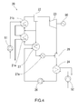
FIG. 4 is a schematic system diagram of the steam power cycle system according to the other embodiment of the present invention; - [
FIG. 5 ]
FIG. 5 is a schematic system diagram of a system of Kalina cycle serving as Comparison No. 1 relative to the steam power cycle system according to the embodiment of the present invention; - [
FIG. 6 ]
FIG. 6 is a schematic system diagram of a system of Uehara cycle serving as Comparison No. 2 relative to the steam power cycle system according to the embodiment of the present invention; - [
FIG. 7 ]
FIG. 7 is a descriptive view of a theoretical temperature change state in a heat exchanger in the conventional steam power cycle; and - [
FIG. 8] FIG. 8 is a conceptual diagram of temperature change in a condenser in the conventional steam power cycle. - Now, the first embodiment of the present invention will be described below with reference to
FIG. 1 . The present embodiment will be described as an example in which the present invention is applied to a power generation apparatus by an ocean thermal energy conversion. - In
FIG. 1 as indicated above, a steampower cycle system 10 according to this embodiment of the present invention is provided with anevaporator 11 that makes heat exchange of a working fluid composed of ammonia and water with a high-temperature seawater as a claimed high-temperature fluid and elevates the temperature of the working fluid to evaporate at least part of it; a gas-liquid separator 12 that separates the working fluid from theevaporator 11 into a gas phase substance and a liquid phase substance; aturbine 13 as a claimed expander that operates by receiving the working fluid in a gas phase as introduced, which has been separated by the gas-liquid separator 12, and converts heat energy held by the working fluid into a power; first andsecond condensers turbine 13 with a cold deep seawater as a claimed low-temperature fluid, etc., to condense it and convert it into a liquid phase; apump 16 that pumps the working fluid taken out from thecondensers evaporator 11; aregenerator 17 that makes heat exchange of the working fluid in a liquid phase, which has been separated by the gas-liquid separator 12, with the working fluid, which has been pumped out toward theevaporator 11; and the first andsecond mixers liquid separator 12 and passed through theregenerator 17, with the working fluid from theturbine 13. - Of these structural components, the
turbine 13 and thepump 16 are the same as the known devices used in a commonly-used steam power cycle and description of them will be omitted. - The power generation apparatus by an ocean thermal energy conversion is composed of such a steam
power cycle system 10 and apower generator 50 driven by theturbine 13. The above-mentionedpower generator 50 is the same as a known power generator used for power generation, which is operated by a driving source of a turbine, and the detailed description of it will be omitted. - The above-mentioned
evaporator 11 has a known structure as a heat exchanger that permits the working fluid in a liquid phase and a high-temperature fluid as the high-temperature heat source to flow in the inside, and makes heat exchange between the working fluid and the high-temperature fluid, and the detailed description of it will be omitted. A channel communicating with theregenerator 17 is connected to theevaporator 11 on the inlet side of the working fluid so that the working fluid, which has been heated through the heat exchange in theregenerator 17, flows into theevaporator 11. A channel communicating with the gas-liquid separator 12 is connected to it on the outlet side of the working fluid so that the working fluid, which has been heated through the heat exchange in theevaporator 11, flows into the gas-liquid separator 12. - The above-mentioned gas-
liquid separator 12 is a known device to separate the working fluid, which has been heated to a high temperature through the heat exchange by theevaporator 11 to be converted into a gas-liquid two-phase, into a gas phase substance and a liquid phase substance, and the detailed description of it will be omitted. The working fluid is separated into the gas phase substance and the liquid phase substance in the above-mentioned gas-liquid separator 12, the working fluid in a gas phase flows toward theturbine 13 through the channel communicating with the inlet side of theturbine 13, and the working fluid in a liquid phase flows toward theregenerator 17 through the channel communicating with theregenerator 17. - The
first mixer 18 as described above is communicated with the outlet of theturbine 13, the inlet of thefirst condenser 14 and the outlet of theregenerator 17 so as to cause the working fluid in a gas phase from theturbine 13 and the working fluid in a liquid phase from theregenerator 17 to flow simultaneously in a mixed state, or where appropriate, to cause the working fluid in a liquid phase to absorb a part of the working fluid in a gas phase. The working fluid in a liquid phase and the working fluid remaining in a gas phase flow in a gas-liquid two-phase as kept from thefirst mixer 18 toward thefirst condenser 14. - The
second mixer 19 as described above is communicated with the outlet of theturbine 13, the outlet of thefirst condenser 14 and the inlet of thesecond condenser 15 so as to cause the working fluid in a gas phase from theturbine 13 and the working fluid in a liquid phase from thefirst condenser 14 to flow simultaneously in a mixed state, or where appropriate, to cause the working fluid in a liquid phase to absorb a part of the working fluid in a gas phase. The working fluid in a liquid phase and the working fluid remaining in a gas phase flow in a gas-liquid two-phase as kept from thesecond mixer 19 toward thesecond condenser 15. - The
condensers first condenser 14 and thesecond condenser 15. Of these condensers, thefirst condenser 14 is communicated with thefirst mixer 18 and causes the working fluid in a gas-liquid two-phase to flow into it and causes also the low-temperature fluid as the low-temperature heat source to flow through it so as to make heat exchange between the working fluid and the low-temperature fluid. - The
second condenser 15 causes the working fluid in a gas-liquid two-phase from thesecond mixer 19 to flow into it and causes also the predetermined low-temperature fluid as the low-temperature heat source to flow through it so as to make heat exchange between the working fluid and the low-temperature fluid. - The
first condenser 14 and thesecond condenser 15 has the same structure as a known heat exchanger to make heat exchange between the working fluid and the low-temperature fluid, and the detailed description of them will be omitted. - The
first condenser 14 cools the working fluid in a liquid phase and condenses the working fluid in a gas phase by making simultaneously heat exchange of the working fluids in a gas phase and a liquid phase, respectively from thefirst mixer 18 with the low-temperature fluid as described above. - The
second condenser 15 cools the working fluid in a liquid phase and condenses the working fluid in a gas phase by making simultaneously heat exchange of the working fluids in a gas phase and a liquid phase, respectively from thesecond mixer 19 with the low-temperature fluid as described above. - These
condensers condensers second condenser 15 and then go toward thefirst condenser 14. - There is provided on the posterior side of the
second condenser 15 thepump 16 to pump all the working fluid in a liquid phase also including the condensed of the working fluid in a gas phase from thecondenser 15 toward theregenerator 17 and theevaporator 11. - The
regenerator 17 is a heat exchanger to make heat exchange between the working fluid having a low temperature before flowing from thesecond condenser 15 through thepump 16 into theevaporator 11, and the working fluid having a high temperature in a liquid phase immediately after being separated from the working fluid in a gas phase by the gas-liquid separator 12. It has the same structure as a known heat exchanger in the same manner as theevaporator 11 and thecondensers - In this
regenerator 17, the working fluid, which has been introduced from the side ofpump 16 and heated through heat exchange with the working fluid having a high temperature in a liquid phase from the other gas-liquid separator 12, flows toward the inlet side of theevaporator 11, while the working fluid, which has been introduced from the side of the gas-liquid separator 12, passes through theregenerator 17 and then flows toward thefirst mixer 18. - There is provided a
decompression unit 17a in the middle of the channel for the working fluid in a liquid phase flowing from thisregenerator 17 toward thefirst mixer 18 so that the working fluid in a liquid phase from the regenerator 17 passes through thedecompression unit 17a to decrease its pressure and then is introduced into thefirst mixer 18. An auxiliary pump to pressurize the working fluid and pump it out may be provided between the respective devices as described above for constituting the steampower cycle system 10, where appropriate. - Now, an operation of the steam power cycle system according to the embodiment of the present invention will be described. It is assumed that a high-temperature seawater as the high-temperature fluid and a low-temperature seawater as the low-temperature fluid are continuously introduced into the
evaporator 11 and thecondensers - In the
evaporator 11, there is made heat exchange between the working fluid and the high-temperature seawater as the high-temperature fluid, which is introduced while being pressurized by anexternal pump 51. The working fluid as heated by such heat exchange converts into a gas-liquid two-phase by evaporation of a part of it, i.e., mainly ammonia having a low-boiling point due to the raised temperature. The working fluid having such a high temperature in the gas-liquid two-phase flows from the evaporator and reaches the gas-liquid separator 12. - The working fluid having a high temperature is separated into a gas phase and a liquid phase in the gas-
liquid separator 12, and the working fluid having a high temperature in a gas phase from the gas-liquid separator 12 flows in a channel toward theturbine 13 and the working fluid having a high temperature in a liquid phase flows in a channel from the gas-liquid separator 12 toward theregenerator 17. The working fluid in a liquid phase, which has been discharged from theregenerator 17, passes through thedecompression unit 17a and is introduced into thefirst mixer 18. - The working fluid having a high temperature in a gas phase, which has been discharged from the gas-
liquid separator 12, contains a main constituent of ammonia having a low-boiling point (about 99%), and such a working fluid in a gas phase reaches theturbine 13 to operate it. Thepower generator 50 is driven by thisturbine 13 so that heat energy is converted into a usable power, and further an electric power. The working fluid in a gas phase after being expanded by theturbine 13 for performing the task comes into a state in which a pressure and a temperature are decreased. - The working fluid in a gas phase, which has been discharged from the
turbine 13, flows in a channel branching into two on posterior side of the outlet of the turbine, and a part of the fluid is introduced into thefirst mixer 18 and the remaining is introduced into thesecond mixer 19. - On the other hand, the working fluid having a high temperature in a liquid phase, which has been discharged from the gas-
liquid separator 12, is introduced into theregenerator 17. Theregenerator 17 makes heat exchange between the working fluid having a high temperature in a liquid phase as introduced from this gas-liquid separator 12 and the working fluid in a liquid phase flowing from thepump 16 toward theevaporator 11, to recover heat held by the working fluid on the high-temperature side to raise a temperature of the working fluid flowing toward theevaporator 11. The working fluid in a liquid phase from the gas-liquid separator 12, which has been cooled through the heat exchange in thisregenerator 17, is discharged from theregenerator 17 and then passes through thedecompression unit 17a and is introduced into thefirst mixer 18. - In the
first mixer 18, the working fluid in a gas phase as introduced from theturbine 13 comes into contact with the working fluid in a liquid phase, which has flowed from theregenerator 17 and passed through thedecomposition unit 17a and then been introduced into it, to be mixed together, or sometimes a part of the working fluid in a gas phase is absorbed by the working fluid in a liquid phase, and is converted into a liquid phase. The working fluid remaining in a gas phase flows together with the working fluid in a liquid phase toward thefirst condenser 14, and the working fluid is introduced in a gas-liquid two-phase into thecondenser 14. - In the
first condenser 14, the working fluid in a gas-liquid two-phase as introduced from thefirst mixer 18 is caused to make heat exchange with the cold seawater as the low-temperature fluid, which has once passed through thesecond condenser 15 and then introduced into it, and when the whole of the working fluid is cooled, the working fluid in a gas phase is condensed into a liquid phase due to the cooling by the heat exchange. The working fluid, which has almost been converted into a liquid phase, is discharged from thefirst condenser 14 to the outside and then reaches thesecond mixer 19. - During such condensation, a substance having a high-boiling point of the working fluid in a gas phase first condenses and the temperature of the working fluid changes rapidly. Then, the temperature transitions into the similar state to an isothermal change and the temperature of the working fluid becomes to an approximate temperature at the outlet of the
first condenser 14 for the low-temperature fluid. - The
second mixer 19 received a part of the working fluid in a gas phase as introduced from theturbine 13. The working fluid having a high temperature in a gas phase comes into contact with the working fluid in a liquid phase, which has been introduced from thefirst condenser 14 to be mixed together, or sometimes a part of the working fluid in a gas phase is absorbed by the working fluid in a liquid phase, and is converted into a liquid phase. - The working fluid remaining in a gas phase flows together with the working fluid in a liquid phase toward the
second condenser 15, and the working fluid is introduced in a gas-liquid two-phase into thecondenser 15. - The concentration of ammonia of the working fluid as introduced into the
second condenser 15 becomes higher than that of the working fluid in thefirst condenser 14 by joining a part of the working fluid in a gas phase having a high concentration of ammonia from theturbine 13 together with the working fluid in a liquid phase as introduced from thefirst condenser 14. - In the
second condenser 15, the working fluid in a gas-liquid two-phase as introduced from thesecond mixer 19 is caused to make heat exchange with the cold seawater having a low temperature as separately introduced as the low-temperature fluid and when the whole of the working fluid is cooled, the working fluid in a gas phase is condensed into a liquid phase due to the cooling by the heat exchange. - During such condensation, a substance having a high-boiling point of the working fluid in a gas phase first condenses and the temperature of the working fluid changes rapidly. Then, the temperature transitions into the similar state to an isothermal change and the temperature of the working fluid becomes to an approximate temperature at the outlet of the condenser for the low-temperature fluid. However, the concentration of ammonia of the working fluid in the
second condenser 15 becomes higher than that of the working fluid in thefirst condenser 14, and the condensation temperature of the working fluid in thesecond condenser 15 becomes lower than the condensation temperature of the working fluid in thefirst condenser 14. Thus, it is possible to decrease sufficiently the temperature of the working fluid to make it close to the temperature of the low-temperature fluid by causing it to pass through the twocondensers - The working fluid, which has almost been converted into a liquid phase in this manner, comes out from the
second condenser 15 and then passes through thepump 16 to be pressurized and flows toward theregenerator 17. Then, the working fluid is introduced into theregenerator 17 and caused to make heat exchange with the working fluid in a liquid phase after separation by the gas-liquid separator 12 as described above to elevate the temperature, and comes out from theregenerator 17 and returns to the inside of theevaporator 11, and then the heat exchange step in theevaporator 11 and the subsequent steps are repeated in the same manner as described above. - The seawaters as the low-temperature fluid, which have continuously been used for the respective heat exchanges in the
second condenser 15 and thefirst condenser 14, have been exposed to heat from the working fluids, with the result that the temperature of them are elevated to a predetermined temperature. These seawaters come out from thecondenser 14 and are discharged into an outside of the system such as a sea. The seawater as the high-temperature fluid, which has the decreased temperature due to the heat exchange with the working fluid in theevaporator 11, comes out from theevaporator 11 and is also discharged into an outside of the system such as sea. - On the other hand, new seawater is supplied for the heat exchange in the
evaporator 11 and thecondensers pumps power cycle system 10. - Seawater existing in extremely large quantity is used as the high-temperature fluid and the low-temperature fluid and an influence of heat held by the seawater after the heat exchange on the whole of seawater, after discharging the seawater after the heat exchange into the sea outside of the system, i.e., the temperature change of the whole of seawater after the discharge is vanishingly small. The temperature change does not occur in the seawater as newly introduced into the
evaporator 11 and thecondensers - In the steam power cycle system according to the embodiment of the present invention, there is provided a plurality of
condensers turbine 13 is introduced into therespective condensers respective condensers respective condensers second condenser 15 at the posterior side, thus making it possible to make the condensation temperature of the working fluid lower than that of thefirst condenser 14 in the anterior stage. It is therefore possible to make the temperature of the working fluid close to the respective different temperatures of the low-temperature fluids in the respective condensers, and to decrease gradually the temperatures of the working fluids on the outlet side of therespective condensers - In the steam power cycle system according to the embodiment as described above of the present invention, the two
condensers turbine 13, which is taken out from the channel for the working fluid communicating with the outlet of the turbine, is joined with the working fluid at the respective stage from the condenser at the anterior stage between the respective condensers, so as to cause the respective condensers to condense the working fluid in a gas phase, in the same manner as the embodiment as described above of the present invention. Increase in the number of stage of the condenser results in achieving a state in which the temperature of the working fluid, which has been decreased by passing through the condenser at the final stage, may be lower than the low-temperature fluid, which has been subjected to the heat exchange in all the condensers to elevate the temperature at a maximum, thus making it possible to decrease the temperature of the working fluid in a plurality of condensers to make it possibly close to the temperature of the low-temperature fluid, leading to a further improvement in cycle heat efficiency. - In the steam power cycle system according to the embodiment as described above of the present invention, there is applied a cycle structure in which the two
condensers liquid separator 22, is joined together with the working fluid in a gas phase from theturbine 13 in the mixer18, and a system in which a part of the working fluid in a gas phase from theturbine 13 is joined together with the respective working fluids flowing therespective condensers turbines condenser 15 in aheater 40, as shown inFIG. 2 , thus making it possible to decrease the temperature of the working fluid in a plurality ofcondensers - Now, the second embodiment of the present invention will be described below with reference to
FIG. 3 . - In
FIG. 3 as indicated above, a steampower cycle system 20 according to this embodiment of the present invention is provided with a gas-liquid separator 22, aturbine 23,condenser pump 26, aregenerator 27 andmixers evaporators liquid separator 22, is joined together with the working fluid directed to thesecond evaporator 21 b, which has been provided to cause the working fluid to flow through it at a posterior stage, and then introduced into thesecond evaporator 21 b. - The power generation apparatus by an ocean thermal energy conversion is composed of such a steam
power cycle system 20 according to this embodiment of the present invention and apower generator 50 driven by theturbine 23. Theturbine 23, thecondensers pump 26, theregenerator 27, and themixers - Concerning the connection of the channels for the high-temperature fluid and the low-temperature fluid in the steam
power cycle system 20, there is adopted a passing order as set in which the low-temperature fluid flows from thesecond condenser 25 to thefirst condenser 24 in the same manner as the first embodiment of the present invention, as well as a passing order as set in which the high-temperature fluid flows from thesecond evaporator 21 b to thefirst evaporator 21a. - The above-mentioned
first evaporator 21 a permits the working fluid and a high-temperature seawater as the abovementioned high-temperature heat source to flow in the inside, makes heat exchange between the working fluid and the high-temperature fluid, and elevates the temperature of the working fluid to evaporate a part of it, thus providing the working fluid in a gas phase. It has the same known heat exchanger structure as theevaporator 11 and thecondensers - A channel communicating with the
regenerator 27 is connected to thefirst evaporator 21 a on the inlet side of the working fluid so that the working fluid, which has been heated through the heat exchange in theregenerator 27, flows into the evaporator 21 a. A channel communicating with thesecond evaporator 21 b is connected to it on the outlet side of the working fluid so that the working fluid, which has been heated through the heat exchange in thefirst evaporator 21 a, flows into thesecond evaporator 21 b. - The above-mentioned
second evaporator 21 b permits the working fluid in a liquid phase and a high-temperature seawater as the abovementioned high-temperature heat source to flow in the inside, makes heat exchange between the working fluid and the high-temperature fluid, and elevates the temperature of the working fluid to evaporate a part of it, thus providing the working fluid in a gas phase in the same manner as thefirst evaporator 21 a. It has the same known heat exchanger structure as thefirst evaporator 21 a as described above, and the detailed description of it will be omitted. - A channel communicating with, in addition to the
first evaporator 21 a, the outlet for the working fluid in a liquid phase of the gas-liquid separator 22, is connected to thesecond evaporator 21 b on the inlet side of the working fluid, and a channel communicating with the inlet of the gas-liquid separator 22 is connected to the outlet side of the working fluid, so that the working fluid from thefirst evaporator 21 a and the working fluid from the gas-liquid separator 22 are joined together and these working fluids are heated through the heat exchange in thesecond evaporator 21 b, and then reach the gas-liquid separator 22. - The above-mentioned gas-
liquid separator 22 is a known device to separate the working fluid, which has been heated to a high temperature through the heat exchange with the high-temperature seawater by the evaporator 21 to be converted into a gas-liquid two-phase, into a gas phase substance and a liquid phase substance in the same manner as the first embodiment of the present invention, and the detailed description of it will be omitted. The working fluid is separated into the gas phase substance and the liquid phase substance in this gas-liquid separator 22, and the working fluid in a gas phase flows toward theturbine 23 through the channel communicating with the inlet side of theturbine 23. - Meanwhile, a part of the working fluid in a liquid phase passes through the channel by which the outlet side of the working fluid in a liquid phase of the gas-
liquid separator 22 and the inlet side of thesecond evaporator 21b are communicated with each other, is directed toward the inlet side of thesecond evaporator 21 b, and then joined together with the working fluid flowing from thefirst evaporator 21 a to thesecond evaporator 21 b, and enters thesecond evaporator 21 b. The remaining of the working fluid in a liquid phase passes through the channel communicating with theregenerator 27 and is directed toward theregenerator 27. - Now, an operation of the steam power cycle system according to the embodiment of the present invention will be described. It is assumed that a high-temperature seawater as the high-temperature fluid and a low-temperature seawater as the low-temperature fluid are continuously introduced into the
evaporators condensers - In the
first evaporator 21 a, there is made heat exchange between the high-temperature seawater as the high-temperature fluid, which has once passed through thesecond evaporator 21 b, all the working fluid in a liquid phase, which has been introduced from the channels for the working fluid communicating with theregenerator 27. The working fluid as heated by such heat exchange converts into a gas phase by evaporation of a part of it, i.e., mainly ammonia having a low-boiling point due to the raised temperature. - The working fluid, which has been subjected to the elevation of temperature in the
first evaporator 21 a and converted into a gas-liquid two-phase, comes out from the evaporator 21 a and is joined together with a part of the working fluid having a high temperature in a liquid phase, which has been separated by the gas-liquid separator 22, and then introduced into thesecond evaporator 21b. - A percentage of water in the working fluid as introduced into the
second evaporator 21 b becomes higher than that of the working fluid in thefirst evaporator 21 a by joining a part of the working fluid in a liquid phase as separated by the gas-liquid separator 22, i.e., the working fluid in a liquid phase having a higher percentage of water of a high-boiling substance together with the working fluid from thefirst evaporator 21 a. - The
second evaporator 21 b makes heat exchange of a combination of the working fluid in a gas-liquid two-phase from thefirst evaporator 21 a and a part of the working fluid having a high temperature in a liquid phase as separated by the gas-liquid separator 22, with the high-temperature seawater as introduced as the high-temperature fluid while being subjected to pressure by theexternal pump 51, and the working fluid as heated through the heat exchange further evaporates a part in a liquid phase along with the elevated temperature. - During such evaporation, a substance having a low boiling point of the working fluid in a liquid phase first evaporates, the temperature of the working fluid rapidly changes, and then it transitions into the similar state to an isothermal change and becomes to an approximate temperature at the outlet of the evaporator for the high-temperature fluid. However, a percentage of water in the working fluid as introduced into the
second evaporator 21 b becomes higher than that of the working fluid in thefirst evaporator 21 a, and the evaporation temperature of the working fluid in thesecond evaporator 21 b becomes higher than the evaporation temperature of the working fluid in thefirst evaporator 21 a. Thus, it is possible to increase sufficiently the temperature of the working fluid to make it close to the temperature of the high-temperature fluid by causing it to pass through the twoevaporators - The working fluid, which has been subjected to elevation of temperature by the
second evaporator 21 b to be converted into a gas-liquid two-phase at a high temperature, comes out from thesecond evaporator 21 b and then reaches the gas-liquid separator 22. The working fluid having a high temperature is separated into the gas phase substance and the liquid phase substance in the gas-liquid separator 22, and the working fluid having a high temperature in a gas phase comes out from the gas-liquid separator 22 and then flows toward theturbine 23. While the working fluid having a high temperature in a liquid phase comes out from the gas-liquid separator 22 to theregenerator 27, a part of the working fluid in a liquid phase is divided from the fluid, which is directed to theregenerator 27, and flows a channel extending from the gas-liquid separator 22 to the inlet side of thesecond evaporator 21 b, and then is introduced into thesecond evaporator 21 b together with the working fluid, which has come out from thefirst evaporator 21a. - The
turbine 23 is driven by the working fluid having a high temperature in a gas phase, which has come out from the gas-liquid separator 22 and then reached theturbine 23. Thepower generator 50 is driven by thisturbine 23 so that heat energy is converted into a usable power, and further an electric power. The working fluid in a gas phase after being expanded by theturbine 13 for performing the task comes into a state in which a pressure and a temperature are decreased. The working fluid in a gas phase, which has been discharged from theturbine 23, is introduced into thefirst mixer 28 and thesecond mixer 29, respectively, in the same manner as the first embodiment as described above of the present invention. - On the other hand, the working fluid having a high temperature in a liquid phase, which has been discharged from the gas-
liquid separator 22, is introduced into theregenerator 27. Theregenerator 27 makes heat exchange between the working fluid having a high temperature in a liquid phase as introduced from this gas-liquid separator 22 and the working fluid in a liquid phase flowing from thepump 26 toward thefirst evaporator 21 a, to recover heat held by the working fluid on the high-temperature side to raise a temperature of the working fluid flowing toward the evaporator 21 a. The working fluid in a liquid phase from the gas-liquid separator 22, which has been cooled through the heat exchange in thisregenerator 27, is discharged from theregenerator 27 and then passes through thedecompression unit 27a and is introduced into thefirst mixer 28. - In the
first mixer 28, the working fluid in a gas phase as introduced from theturbine 23 comes into contact with the working fluid in a liquid phase, which has flowed from theregenerator 27 and passed through thedecomposition unit 27a and then been introduced into it, to be mixed together, or sometimes a part of the working fluid in a gas phase is absorbed by the working fluid in a liquid phase, and is converted into a liquid phase, in the same manner as the first embodiment as described above of the present invention. The working fluid remaining in a gas phase flows together with the working fluid in a liquid phase toward thefirst condenser 24, and the working fluid is introduced in a gas-liquid two-phase into thefirst condenser 24. - In the
first condenser 24, the working fluid in a gas-liquid two-phase as introduced from thefirst mixer 28 is caused to make heat exchange with the cold seawater as the low-temperature fluid, which has once passed through thesecond condenser 25 and then introduced into it, and when the whole of the working fluid is cooled, the working fluid in a gas phase is condensed into a liquid phase due to the cooling by the heat exchange. The working fluid, which has almost been converted into a liquid phase, is discharged from thefirst condenser 24 to the outside and then reaches thesecond mixer 29. - During such condensation, a substance having a high-boiling point of the working fluid in a gas phase first condenses and the temperature of the working fluid changes rapidly. Then, the temperature transitions into the similar state to an isothermal change and the temperature of the working fluid becomes to an approximate temperature at the outlet of the
first condenser 24 for the low-temperature fluid. - The
second mixer 29 received a part of the working fluid in a gas phase as introduced from theturbine 23, in the same manner as the first embodiment as described above of the present invention. The working fluid having a high temperature in a gas phase comes into contact with the working fluid in a liquid phase, which has been introduced from thefirst condenser 24 to be mixed together, or sometimes a part of the working fluid in a gas phase is absorbed by the working fluid in a liquid phase, and is converted into a liquid phase. The working fluid remaining in a gas phase flows together with the working fluid in a liquid phase toward thesecond condenser 25, and the working fluid is introduced in a gas-liquid two-phase into thecondenser 25. - The concentration of ammonia of the working fluid as introduced into the
second condenser 25 becomes higher than that of the working fluid in thefirst condenser 24 by joining a part of the working fluid in a gas phase having a high concentration of ammonia from theturbine 23 together with the working fluid in a liquid phase as introduced from thefirst condenser 24, in the same manner as the first embodiment as described above of the present invention. - In the
second condenser 25, the working fluid in a gas-liquid two-phase as introduced from thesecond mixer 29 is caused to make heat exchange with the cold seawater having a low temperature as separately introduced as the low-temperature fluid and when the whole of the working fluid is cooled, the working fluid in a gas phase is condensed into a liquid phase due to the cooling by the heat exchange. - During such condensation, a substance having a high-boiling point of the working fluid in a gas phase first condenses and the temperature of the working fluid changes rapidly. Then, the temperature transitions into the similar state to an isothermal change and the temperature of the working fluid becomes to an approximate temperature at the outlet of the condenser for the low-temperature fluid. However, the concentration of ammonia of the working fluid in the
second condenser 25 becomes higher than that of the working fluid in thefirst condenser 24, and the condensation temperature of the working fluid in thesecond condenser 25 becomes lower than the condensation temperature of the working fluid in thefirst condenser 24. Thus, it is possible to decrease sufficiently the temperature of the working fluid to make it close to the temperature of the low-temperature fluid by causing it to pass through the twocondensers - The working fluid, which has almost been converted into a liquid phase in this manner, comes out from the
second condenser 25 and then passes through thepump 26 to be pressurized and flows toward theregenerator 27. Then, the working fluid is introduced into theregenerator 27 and caused to make heat exchange with the working fluid in a liquid phase after separation by the gas-liquid separator 22 as described above to elevate the temperature, and comes out from theregenerator 27 and returns to the inside of thefirst evaporator 21 a, and then the heat exchange step in thefirst evaporator 21 a and the subsequent steps are repeated in the same manner as described above. - In the steam power cycle system according to the embodiment of the present invention, there is provided a plurality of
condensers liquid separator 22, is jointed together with the working fluids passing between therespective evaporators respective evaporators first evaporator 21 a and the working fluid in a liquid phase having a high ratio of water having a high-boiling point of the mixture to introduce them into thesecond evaporator 21 b, with the result that the ratio of the substance having a high-boiling point of the working fluid becomes higher at thesecond evaporator 21 b on the posterior side, thus making it possible to make the evaporation temperature of the working fluid higher than that of thefirst evaporator 21 a on the anterior side. It is therefore possible to make the temperature of the working fluid close to the respective different temperatures of the high-temperature fluids in therespective evaporators - In the steam power cycle system according to the embodiment as described above of the present invention, a plurality of
evaporators condensers FIG. 4 . - So long as there is adopted a structure in which a plurality of evaporators is provided and a part of the working fluid in a liquid phase, which has been separated from the gas phase substance by the gas-liquid separator, is joined together with the respective working fluids flowing between the respective evaporators, the remaining structure of the system may be based on a steam power cycle such as so-called Kalina cycle or Uehara cycle, which uses the non-azeotropic mixture as the working fluid, thus making it possible to increase the temperature of the working fluid in a plurality of evaporators to make it possibly close to the temperature of the high-temperature fluid, leading to an improvement in cycle heat efficiency in the same manner as the embodiment as described above of the present invention.
- Conditions such as amounts of heat input and output, pressures, etc for the steam power cycle system according to the present invention were used to determine heat efficiencies, and the resultants were compared with those for the conventional steam power cycle as comparative examples for assessment.
- Concerning, as an example of the present invention, the same steam power cycle system as the first embodiment of the present invention as described above, i.e., the system in which the mixture of ammonia and water was used as the working fluid, and the working fluid from the turbine was introduced into each of the condensers provided in two stages, so that there was made heat exchange between the working fluids in gas and liquid phases and the low-temperature fluid in the respective condensers, values such as heat efficiencies were determined. For determination, various values of physical properties indicative of conditions of pressure, temperature, etc. of the working fluid at each of points (1 to 12) of the cycle as shown in
FIG. 1 were determined with the use of assumed values based on the actual environment such as a heat-transfer performance of the heat exchanger such as the evaporator, condenser, etc.; temperature conditions of the high-temperature fluid and the low-temperature fluid serving as the heat source; and the like, and then the values of the theoretical heat efficiencies of the cycle were calculated. - Concerning the important conditions for the steam power cycle of this example of the present invention, there was used as the working fluid the mixture having a ratio by weight of ammonia to water of 95:5, i.e., having a mass fraction of ammonia/water of 0.95kg/kg, and the inlet temperature TWSi of the evaporator on the high-temperature fluid side was set as 30°C and the outlet temperature TWSo was set as 26°C. The inlet temperature TCSi of the series of condensers on the low-temperature fluid side was set as 8°C and the outlet temperature TCSo was set as 11°C.
- Concerning the other conditions for the stem power cycle, a flow rate of the high-temperature fluid was set as 400t/h, a flow rate of the low-temperature fluid, 400t/h, a flow rate of the working fluid, 140t/h, a heat-transfer performance of the evaporator, 20000kW/K, a heat-transfer performance (overall value) of the condenser, 20000kW/K, and a heat-transfer performance of the regenerator, 150kW/K.
- The liquid phase substance of the working fluid as separated from the gas phase substance (a flow rate of 88.3t/h, and being 63.1 % of the total) by the gas-
liquid separator 12 was 36.9% of the whole working fluid. The fluid of 71.2% of the working fluid in a gas phase from theturbine 13 flowed toward thefirst mixer 18 and the remaining working fluid in a gas phase (a flow rate of 25.4t/h) flowed toward thesecond mixer 19. - There were calculated, based on such conditions, the respective values of pressure "P", temperature "T", ammonia mass fraction "Y", specific volume "V", specific enthalpy "h", specific entropy "s" and dryness "x" of the working fluid at each of the points (1 to 12) of the cycle. The calculation results are shown in Table 1.
[Table 1] POINT T[°C] P[MPa] Y[kg/kg] V[m3/kg] h[kJ/kg] s[kJ/kgK] x[-] 1 15.14 0.642 0.909 0.0653 593.5 2.584 0.27 2 12.67 0.642 0.950 0.0016 222.6 1.212 0 3 12.74 0.929 0.950 0.0016 223.1 1.212 - 4 17.09 0.929 0.950 0.0016 243.5 1.283 - 5 26.94 0.929 0.950 0.0897 1028.1 3.916 0.54 6 26.94 0.929 1.000 0.1413 1495.6 5.393 1.00 7 26.94 0.929 0.865 0.0015 228.8 1.390 0 8 15.16 0.929 0.865 0.0015 173.4 1.202 - 9 15.20 0.642 0.865 0.0015 173.4 1.203 0 10 11.48 0.642 1.000 0.1933 1448.6 5.393 0.97 11 13.81 0.642 0.909 0.0015 198.3 1.210 0 12 13.75 0.642 0.950 0.0883 760.5 3.091 0.38 - Concerning, as Sample for Comparison No. 1, the conventionally known steam power cycle system (see
FIG. 5 ), which corresponded to the so-called Kalina cycle in which there were not used the second mixer and the second condenser of the structural components as described above of the present invention, and the total amount of the working fluid in a gas phase from the turbine was directed toward thefirst mixer 18, the conditions such as pressure, temperature, etc. of the working fluid at each of the points (1 to 10) of the cycle as shown inFIG. 5 were determined in the same manner as the example of the present invention as described above, and then the theoretical heat efficiencies of the cycle were obtained. - Concerning, as Sample for Comparison No. 2, the conventional steam power cycle system (see
FIG. 6 ), which corresponded to the so-called Uehara cycle in which the working fluid in a gas phase as extracted in the middle between turbines was caused to make heat exchange with the working fluid in a liquid phase, which has passed through the condenser, the conditions such as pressure, temperature, etc. of the working fluid at each of the points (1 to 15) of the cycle as shown inFIG. 6 were determined in the same manner as the example of the present invention as described above, and then the theoretical heat efficiencies of the cycle were obtained. - The conditions such as mass fraction of ammonia, temperature conditions of the high-temperature fluid and the low-temperature fluid, heat-transfer performance of the heat exchanger such as the evaporator, condenser, etc., were the same as those set in the system according to the present invention as described above, unless otherwise stated.
- Concerning different conditions, a flow rate of the working fluid in a gas phase, which has been separated from the liquid phase substance by the gas-liquid separator and then flowed toward the turbine, was 87.3t/h (62.4% of the working fluid) in Sample for Comparison No. 1, and was 90.3t/h (64.5% of the working fluid) in Sample for Comparison No. 2.
- In Sample for Comparison No. 2, a flow rate of the working fluid in a gas phase, which was to be extracted and then flowed toward the heater, of the working fluid in a gas phase as introduced into the turbine, was 0.364t/h (0.403% of the amount of it as being introduced into the turbine, and being 0.26% of the total amount of the working fluid). In addition, the heat-transfer performance of the heater was set as 30kW/K.
- There were calculated, based on such conditions, the respective values of pressure "P", temperature "T", ammonia mass fraction "Y", specific volume "V", specific enthalpy "h", specific entropy "s" and dryness "x" of the working fluid at each of the points of the steam power cycle of the respective samples for comparison (see
FIG. 5 andFIG. 6 ). The calculation results for Sample for Comparison No. 1 are shown in Table 2, and those for Sample for Comparison No. 2, Table 3.[Table 2] POINT T[°C] P[MPa] Y[kg/kg] V[m3/kg] h[kJ/kg] s[kJ/kgK] x[-] 1 15.84 0.662 0.950 0.1190 972.9 3.882 0.52 2 13.57 0.662 0.950 0.0016 226.8 1.227 0 3 13.63 0.932 0.950 0.0016 227.3 1.227 - 4 17.75 0.932 0.950 0.0016 246.7 1.294 - 5 26.94 0.932 0.950 0.0884 1019.5 3.886 0.54 6 26.94 0.932 1.000 0.1408 1495.4 5.391 1.00 7 26.94 0.932 0.867 0.0015 230.6 1.392 0 8 16.00 0.932 0.867 0.0015 179.1 1.217 - 9 16.03 0.662 0.867 0.0015 179.1 1.218 0 10 12.38 0.662 1.000 0.1882 1451.7 5.391 0.97 [Table 3] POINT T[°C] P[MPa] Y[kg/kg] V[m3/kg] h[kJ/kg] s[kJ/kgK] x[-] 1 12.67 0.665 0.950 0.1226 999.4 3.912 0.54 2 13.74 0.665 0.950 0.0016 227.6 1.229 0 3 14.47 0.925 0.950 0.0016 231.2 1.240 - 4 18.21 0.925 0.950 0.0016 248.8 1.301 - 5 27.01 0.925 0.950 0.0922 1045.4 3.974 0.55 6 27.01 0.925 1.000 0.1420 1496.1 5.396 1.00 7 27.01 0.925 0.859 0.0015 225.3 1.387 0 8 16.45 0.925 0.859 0.0015 175.6 1.219 - 9 16.49 0.665 0.859 0.0015 175.6 1.220 0 10 12.59 0.665 1.000 0.1875 1454.0 5.396 0.97 11 18.64 0.795 1.000 0.1606 1476.5 5.396 0.99 12 17.68 0.795 1.000 0.0016 282.5 1.291 0 13 13.80 0.925 0.950 0.0016 228.0 1.229 - 14 14.46 0.925 0.950 0.0016 231.1 1.240 - 15 17.71 0.925 1.000 0.0016 282.7 1.291 0 - Based on the condition of the working fluid at the respective point of the cycle system, as indicated in Table 1 above, the heat efficiency ηth of the cycle of the example of the present invention may be expressed as follows:

wherein,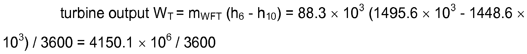


As a result, ηth = (WT - WPWF) / QE = (4150.1 - 70) / 109844 = 0.0371 - Therefore, the heat efficiency of the cycle of the example of the present invention was 3.71%.
- Then, based on the condition of the working fluid at the respective point of the cycle system, as indicated in Table 2 above, the heat efficiency ηth of the cycle of Sample for Comparison No. 1 may be expressed as follows:

wherein,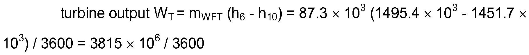


- As a result, ηth = (WT - WPWF) / QE = (3815 - 70) / 108192 = 0.0346
- Therefore, the heat efficiency of the cycle of Sample for Comparison No. 1 was 3.46%.
- Then, based on the condition of the working fluid at the respective point of the cycle system, as indicated in Table 3 above, the heat efficiency ηth of the cycle of Sample for Comparison No. 2 may be expressed as follows:

wherein,


- As a result, ηth = (WT - WPWF) / QE = (3793.5 - 55.9) / 111524 = 0.0335
- Therefore, the heat efficiency of the cycle of Sample for Comparison No. 2 was 3.35%.
- It was revealed from the calculated results of the heat efficiency for the example of the present invention as described above and each of the samples for comparison that the heat efficiency of the steam power cycle system of the example of the present invention was improved remarkably in comparison with the conventional steam power cycles in which the mixture of ammonia and water was used as the working fluid.
- It was recognized from the foregoing that the steam power cycle system of the example of the present invention permitted to improve the heat efficiency of the cycle by condensing the working fluid in a gas phase from the turbine by a plurality of condensers to decrease the temperature and pressure of the working fluid at the outlet of the condenser at the final stage, thus effectively utilizing the difference in temperature between the high-temperature fluid as the heat source and the low-temperature fluid.
-
- 10, 20
- steam power cycle system
- 11, 21a, 21b
- evaporator
- 12, 22
- gas-liquid separator
- 13, 23
- turbine
- 13a, 13b
- turbine
- 14, 15, 24, 25
- condenser
- 16, 26
- pump
- 17, 27
- regenerator
- 18, 19, 28, 29
- mixer
- 40
- heater
- 50
- power generator
- 51, 52
- pump
Claims (3)
- A steam power cycle system, which comprises:an evaporator that causes a working fluid of non-azeotropic mixture to make heat exchange with a predetermined high-temperature fluid and evaporates at least part of said working fluid;a gas-liquid separator that separates the working fluid having a high temperature and obtained by said evaporator into a gas phase substance and a liquid phase substance;an expander that receives the gas phase substance of said working fluid as introduced to convert heat energy held by a fluid into a power;a condenser that causes the working fluid in a gas phase from said expander and the working fluid in a liquid phase from said gas-liquid separator together to make heat exchange with a predetermined low-temperature fluid and condenses the gas phase substance; anda pump that pumps the working fluid from said condenser toward said evaporator,wherein:a plurality of condensers is provided as said condenser, each of said condensers having a flow channel on a working fluid side, which is connected in series and each of said condensers having a flow channel on a low-temperature fluid side, which is connected in series, so as to provide a flow channel design in which the low-temperature fluid passes through the respective condensers in reverse order to an order in which the working fluid passes through the condensers;a part of the working fluid in the gas phase from said expander is drawn from a channel for the working fluid leading to an outlet of the expander and is joined together with the working fluid at respective stages, which is discharged from a preceding condenser of adjacent condensers; andthe working fluid in the gas phase is condensed by the condenser, which is placed in a most anterior stage and in a closest position to an outlet of said expander on the channel for the working fluid, and the working fluid in the gas phase as jointed together is also condensed by other respective condenser than said condenser placed in the most anterior stage.
- The steam power cycle system as claimed in Claim 1, wherein:a plurality of evaporators is provided as said evaporator, each of said evaporators having a flow channel on a working fluid side, which is connected in series and each of said evaporators having a flow channel on a high-temperature fluid side, which is connected in series, so as to provide a flow channel design in which the high-temperature fluid passes through the respective evaporators in reverse order to an order in which the working fluid passes through the evaporators;a part of the working fluid in the liquid phase, which has been separated from the working fluid in the gas phase by said gas-liquid separator, is drawn from a channel for the working fluid in the liquid phase leading to an outlet of the gas-liquid separator and is joined together with the working fluid at respective stages, which is discharged from a preceding evaporator of adjacent evaporators; and a temperature of the working fluid in a mixed state is raised by other respective evaporator than the evaporator, which is placed in a most anterior stage and is a closest position to an outlet of said pump on the channel for the working fluid.
- A steam power cycle system, which comprises:an evaporator that causes a working fluid of non-azeotropic mixture to make heat exchange with a predetermined high-temperature fluid and evaporates at least part of said working fluid;a gas-liquid separator that separates the working fluid having a high temperature and obtained by said evaporator into a gas phase substance and a liquid phase substance;an expander that receives the gas phase substance of said working fluid as introduced to convert heat energy held by a fluid into a power;a condenser that causes the working fluid in a gas phase from said expander and the working fluid in a liquid phase from said gas-liquid separator together to make heat exchange with a predetermined low-temperature fluid and condenses the gas phase substance; anda pump that pumps the working fluid from said condenser toward said evaporator,wherein:a plurality of evaporators is provided as said evaporator, each of said evaporators having a flow channel on a working fluid side, which is connected in series and each of said evaporators having a flow channel on a high-temperature fluid side, which is connected in series, so as to provide a flow channel design in which the high-temperature fluid passes through the respective evaporators in reverse order to an order in which the working fluid passes through the evaporators;a part of the working fluid in the liquid phase, which has been separated from the working fluid in the gas phase by said gas-liquid separator, is drawn from a channel for the working fluid in the liquid phase leading to an outlet of the gas-liquid separator and is joined together with the working fluid at respective stages, which is discharged from a preceding evaporator of adjacent evaporators; and a temperature of the working fluid in a mixed state is raised by other respective evaporator than the evaporator, which is placed in a most anterior stage and is a closest position to an outlet of said pump on the channel for the working fluid.
Applications Claiming Priority (2)
| Application Number | Priority Date | Filing Date | Title |
|---|---|---|---|
| JP2011179525A JP5800295B2 (en) | 2011-08-19 | 2011-08-19 | Steam power cycle system |
| PCT/JP2012/070425 WO2013027604A1 (en) | 2011-08-19 | 2012-08-10 | Steam power cycle system |
Publications (3)
| Publication Number | Publication Date |
|---|---|
| EP2765278A1 true EP2765278A1 (en) | 2014-08-13 |
| EP2765278A4 EP2765278A4 (en) | 2015-07-01 |
| EP2765278B1 EP2765278B1 (en) | 2019-08-07 |
Family
ID=47746351
Family Applications (1)
| Application Number | Title | Priority Date | Filing Date |
|---|---|---|---|
| EP12826070.0A Active EP2765278B1 (en) | 2011-08-19 | 2012-08-10 | Steam power cycle system and method of producing power |
Country Status (6)
| Country | Link |
|---|---|
| US (1) | US9328634B2 (en) |
| EP (1) | EP2765278B1 (en) |
| JP (1) | JP5800295B2 (en) |
| KR (1) | KR101885702B1 (en) |
| CN (1) | CN103732864B (en) |
| WO (1) | WO2013027604A1 (en) |
Families Citing this family (33)
| Publication number | Priority date | Publication date | Assignee | Title |
|---|---|---|---|---|
| EP2065641A3 (en) * | 2007-11-28 | 2010-06-09 | Siemens Aktiengesellschaft | Method for operating a continuous flow steam generator and once-through steam generator |
| JP5862133B2 (en) * | 2011-09-09 | 2016-02-16 | 国立大学法人佐賀大学 | Steam power cycle system |
| JP6084879B2 (en) * | 2013-03-29 | 2017-02-22 | メタウォーター株式会社 | Binary power generation system and operation method of binary power generation system |
| WO2014171892A1 (en) * | 2013-04-18 | 2014-10-23 | Lien Chiow Tan | Green engine |
| KR101559538B1 (en) | 2013-11-25 | 2015-10-15 | 한국에너지기술연구원 | An absorber for kalina cycle |
| US9803511B2 (en) | 2015-08-24 | 2017-10-31 | Saudi Arabian Oil Company | Power generation using independent dual organic rankine cycles from waste heat systems in diesel hydrotreating-hydrocracking and atmospheric distillation-naphtha hydrotreating-aromatics facilities |
| US9803506B2 (en) | 2015-08-24 | 2017-10-31 | Saudi Arabian Oil Company | Power generation from waste heat in integrated crude oil hydrocracking and aromatics facilities |
| US9745871B2 (en) * | 2015-08-24 | 2017-08-29 | Saudi Arabian Oil Company | Kalina cycle based conversion of gas processing plant waste heat into power |
| US9803930B2 (en) | 2015-08-24 | 2017-10-31 | Saudi Arabian Oil Company | Power generation from waste heat in integrated hydrocracking and diesel hydrotreating facilities |
| US9803505B2 (en) | 2015-08-24 | 2017-10-31 | Saudi Arabian Oil Company | Power generation from waste heat in integrated aromatics and naphtha block facilities |
| US9803507B2 (en) | 2015-08-24 | 2017-10-31 | Saudi Arabian Oil Company | Power generation using independent dual organic Rankine cycles from waste heat systems in diesel hydrotreating-hydrocracking and continuous-catalytic-cracking-aromatics facilities |
| US9803508B2 (en) | 2015-08-24 | 2017-10-31 | Saudi Arabian Oil Company | Power generation from waste heat in integrated crude oil diesel hydrotreating and aromatics facilities |
| US9725652B2 (en) * | 2015-08-24 | 2017-08-08 | Saudi Arabian Oil Company | Delayed coking plant combined heating and power generation |
| US9803513B2 (en) | 2015-08-24 | 2017-10-31 | Saudi Arabian Oil Company | Power generation from waste heat in integrated aromatics, crude distillation, and naphtha block facilities |
| US10227899B2 (en) | 2015-08-24 | 2019-03-12 | Saudi Arabian Oil Company | Organic rankine cycle based conversion of gas processing plant waste heat into power and cooling |
| KR101940293B1 (en) * | 2016-10-28 | 2019-01-18 | 한국수력원자력 주식회사 | Modularized geothermal power generation system |
| US10626756B2 (en) | 2017-08-08 | 2020-04-21 | Saudi Arabian Oil Company | Natural gas liquid fractionation plant waste heat conversion to power using dual turbines organic Rankine cycle |
| US10684079B2 (en) | 2017-08-08 | 2020-06-16 | Saudi Arabian Oil Company | Natural gas liquid fractionation plant waste heat conversion to simultaneous power and cooling capacities using modified goswami system |
| US10451359B2 (en) | 2017-08-08 | 2019-10-22 | Saudi Arabian Oil Company | Natural gas liquid fractionation plant waste heat conversion to power using Kalina cycle |
| US10480354B2 (en) | 2017-08-08 | 2019-11-19 | Saudi Arabian Oil Company | Natural gas liquid fractionation plant waste heat conversion to simultaneous power and potable water using Kalina cycle and modified multi-effect-distillation system |
| US10436077B2 (en) | 2017-08-08 | 2019-10-08 | Saudi Arabian Oil Company | Natural gas liquid fractionation plant waste heat conversion to potable water using modified multi-effect distillation system |
| US10662824B2 (en) | 2017-08-08 | 2020-05-26 | Saudi Arabian Oil Company | Natural gas liquid fractionation plant waste heat conversion to power using organic Rankine cycle |
| US10663234B2 (en) | 2017-08-08 | 2020-05-26 | Saudi Arabian Oil Company | Natural gas liquid fractionation plant waste heat conversion to simultaneous cooling capacity and potable water using kalina cycle and modified multi-effect distillation system |
| US10494958B2 (en) | 2017-08-08 | 2019-12-03 | Saudi Arabian Oil Company | Natural gas liquid fractionation plant waste heat conversion to simultaneous power and cooling capacities using integrated organic-based compressor-ejector-expander triple cycles system |
| US10690407B2 (en) | 2017-08-08 | 2020-06-23 | Saudi Arabian Oil Company | Natural gas liquid fractionation plant waste heat conversion to simultaneous power and potable water using organic Rankine cycle and modified multi-effect-distillation systems |
| US10480355B2 (en) | 2017-08-08 | 2019-11-19 | Saudi Arabian Oil Company | Natural gas liquid fractionation plant waste heat conversion to simultaneous power, cooling and potable water using modified goswami cycle and new modified multi-effect-distillation system |
| US10443453B2 (en) | 2017-08-08 | 2019-10-15 | Saudi Araabian Oil Company | Natural gas liquid fractionation plant cooling capacity and potable water generation using integrated vapor compression-ejector cycle and modified multi-effect distillation system |
| US10677104B2 (en) | 2017-08-08 | 2020-06-09 | Saudi Arabian Oil Company | Natural gas liquid fractionation plant waste heat conversion to simultaneous power, cooling and potable water using integrated mono-refrigerant triple cycle and modified multi-effect-distillation system |
| US10487699B2 (en) | 2017-08-08 | 2019-11-26 | Saudi Arabian Oil Company | Natural gas liquid fractionation plant waste heat conversion to cooling capacity using kalina cycle |
| DE102017125355B3 (en) * | 2017-10-29 | 2019-01-10 | Carmen Lindner | Method and arrangement for converting heat into kinetic energy |
| JP6363313B1 (en) * | 2018-03-01 | 2018-07-25 | 隆逸 小林 | Working medium characteristic difference power generation system and working medium characteristic difference power generation method using the power generation system |
| JP6409157B1 (en) * | 2018-05-02 | 2018-10-17 | 一彦 永嶋 | Power generation system |
| WO2025181618A1 (en) * | 2024-02-26 | 2025-09-04 | Politecnico Di Milano | Process for operating a working fluid according to a steam thermodynamic cycle to product work |
Family Cites Families (36)
| Publication number | Priority date | Publication date | Assignee | Title |
|---|---|---|---|---|
| DE1808544A1 (en) * | 1968-11-13 | 1970-06-04 | Siemens Ag | Steam turbine plant |
| HU164245B (en) * | 1971-08-03 | 1974-01-28 | ||
| JPS57200607A (en) | 1981-05-30 | 1982-12-08 | Ai Karina Arekusandaa | Generation of energy by operation fluid and regeneration of operation fluid |
| JPS5968505A (en) * | 1982-10-14 | 1984-04-18 | Toshiba Corp | Low boiling point medium cycle plant |
| US4827877A (en) * | 1987-01-13 | 1989-05-09 | Hisaka Works, Limited | Heat recovery system utilizing non-azeotropic medium |
| JPH0794815B2 (en) * | 1993-09-22 | 1995-10-11 | 佐賀大学長 | Temperature difference generator |
| JPH0791211A (en) * | 1993-09-28 | 1995-04-04 | Hisaka Works Ltd | Evaporator for mixed media |
| JP3524582B2 (en) * | 1994-05-27 | 2004-05-10 | 中部電力株式会社 | Non-azeotropic mixed fluid cycle plant |
| JP2611185B2 (en) * | 1994-09-20 | 1997-05-21 | 佐賀大学長 | Energy conversion device |
| DE19626372C1 (en) * | 1996-07-02 | 1997-11-27 | Saarbergwerke Ag | Method and device for improving the efficiency in steam power plants |
| JPH10156314A (en) * | 1996-12-03 | 1998-06-16 | Ebara Corp | Method of recovering energy from waste |
| WO2002101206A1 (en) * | 2001-06-12 | 2002-12-19 | Midwest Research Institute | Stratified vapor generator |
| AU2001277917A1 (en) * | 2001-07-19 | 2003-03-03 | Midwest Research Institute | Mixed working fluid power system with incremental vapor generation |
| US6769256B1 (en) * | 2003-02-03 | 2004-08-03 | Kalex, Inc. | Power cycle and system for utilizing moderate and low temperature heat sources |
| WO2004070173A1 (en) * | 2003-02-03 | 2004-08-19 | Kalex Llc, | Power cycle and system for utilizing moderate and low temperature heat sources |
| US7305829B2 (en) * | 2003-05-09 | 2007-12-11 | Recurrent Engineering, Llc | Method and apparatus for acquiring heat from multiple heat sources |
| DE10335134A1 (en) * | 2003-07-31 | 2005-02-17 | Siemens Ag | Method and device for carrying out a thermodynamic cycle |
| US7264654B2 (en) * | 2003-09-23 | 2007-09-04 | Kalex, Llc | Process and system for the condensation of multi-component working fluids |
| DE102004037417B3 (en) * | 2004-07-30 | 2006-01-19 | Siemens Ag | Method and device for transferring heat from a heat source to a thermodynamic cycle with a working medium comprising at least two substances with non-isothermal evaporation and condensation |
| US7493763B2 (en) * | 2005-04-21 | 2009-02-24 | Ormat Technologies, Inc. | LNG-based power and regasification system |
| GB0511864D0 (en) * | 2005-06-10 | 2005-07-20 | Univ City | Expander lubrication in vapour power systems |
| WO2007000811A1 (en) * | 2005-06-28 | 2007-01-04 | Saga University | Steam power cycle system |
| US7600394B2 (en) * | 2006-04-05 | 2009-10-13 | Kalex, Llc | System and apparatus for complete condensation of multi-component working fluids |
| US7900451B2 (en) * | 2007-10-22 | 2011-03-08 | Ormat Technologies, Inc. | Power and regasification system for LNG |
| DE102008005978B4 (en) * | 2008-01-24 | 2010-06-02 | E-Power Gmbh | Low-temperature power plant and method for operating a thermodynamic cycle |
| US7997076B2 (en) * | 2008-03-31 | 2011-08-16 | Cummins, Inc. | Rankine cycle load limiting through use of a recuperator bypass |
| US8479517B2 (en) | 2009-05-25 | 2013-07-09 | Haruo Uehara | Vapor power cycle apparatus |
| US8627663B2 (en) * | 2009-09-02 | 2014-01-14 | Cummins Intellectual Properties, Inc. | Energy recovery system and method using an organic rankine cycle with condenser pressure regulation |
| WO2011103560A2 (en) * | 2010-02-22 | 2011-08-25 | University Of South Florida | Method and system for generating power from low- and mid- temperature heat sources |
| JP5457880B2 (en) * | 2010-02-24 | 2014-04-02 | メタウォーター株式会社 | Waste heat power generation method and waste heat power generation system |
| IT1402363B1 (en) * | 2010-06-10 | 2013-09-04 | Turboden Srl | ORC PLANT WITH SYSTEM TO IMPROVE THE HEAT EXCHANGE BETWEEN THE SOURCE OF WARM FLUID AND WORK FLUID |
| WO2012048132A2 (en) * | 2010-10-06 | 2012-04-12 | Chevron U.S.A. Inc. | Utilization of process heat by-product |
| US8857185B2 (en) * | 2012-01-06 | 2014-10-14 | United Technologies Corporation | High gliding fluid power generation system with fluid component separation and multiple condensers |
| US20130174552A1 (en) * | 2012-01-06 | 2013-07-11 | United Technologies Corporation | Non-azeotropic working fluid mixtures for rankine cycle systems |
| US8833077B2 (en) * | 2012-05-18 | 2014-09-16 | Kalex, Llc | Systems and methods for low temperature heat sources with relatively high temperature cooling media |
| DE102012210803A1 (en) * | 2012-06-26 | 2014-01-02 | Energy Intelligence Lab Gmbh | Device for generating electrical energy by means of an ORC circuit |
-
2011
- 2011-08-19 JP JP2011179525A patent/JP5800295B2/en active Active
-
2012
- 2012-08-10 CN CN201280040242.2A patent/CN103732864B/en not_active Expired - Fee Related
- 2012-08-10 WO PCT/JP2012/070425 patent/WO2013027604A1/en not_active Ceased
- 2012-08-10 EP EP12826070.0A patent/EP2765278B1/en active Active
- 2012-08-10 KR KR1020147002090A patent/KR101885702B1/en active Active
-
2014
- 2014-02-17 US US14/182,022 patent/US9328634B2/en active Active
Also Published As
| Publication number | Publication date |
|---|---|
| EP2765278B1 (en) | 2019-08-07 |
| KR20140048217A (en) | 2014-04-23 |
| US20140223911A1 (en) | 2014-08-14 |
| CN103732864A (en) | 2014-04-16 |
| EP2765278A4 (en) | 2015-07-01 |
| US9328634B2 (en) | 2016-05-03 |
| JP2013040594A (en) | 2013-02-28 |
| JP5800295B2 (en) | 2015-10-28 |
| KR101885702B1 (en) | 2018-08-06 |
| CN103732864B (en) | 2015-09-02 |
| WO2013027604A1 (en) | 2013-02-28 |
Similar Documents
| Publication | Publication Date | Title |
|---|---|---|
| EP2765278B1 (en) | Steam power cycle system and method of producing power | |
| KR101602754B1 (en) | Steam power cycle device | |
| US8656720B1 (en) | Extended range organic Rankine cycle | |
| EP2021587B1 (en) | A method and system for generating power from a heat source | |
| US7021060B1 (en) | Power cycle and system for utilizing moderate temperature heat sources | |
| EP2312129A1 (en) | Thermoelectric energy storage system having an internal heat exchanger and method for storing thermoelectric energy | |
| CN101018930A (en) | Efficient conversion of heat to useful energy | |
| AU2005233321A1 (en) | Method and device for carrying out a thermodynamic cyclic process | |
| US20150135709A1 (en) | Cascaded power plant using low and medium temperature source fluid | |
| CN102797525A (en) | Low-temperature Rankine circulation system employing non-azeotropic mixed working medium variable components | |
| JP5756900B2 (en) | Distillation equipment | |
| CN101397983B (en) | Working fluid phase changing enthalpy difference sea water temperature difference power machine | |
| KR101917430B1 (en) | Power generating apparatus | |
| KR101294948B1 (en) | Power system for improved thermal and condensing efficiency | |
| US8910477B2 (en) | Thermodynamic cycle | |
| KR20170077159A (en) | A system for high efficiency energy conversion cycle by recycling latent heat of vaporization | |
| DE102004037934B4 (en) | working procedures | |
| Ganesh et al. | Processes assessment in binary mixture plant | |
| WO2015075537A2 (en) | Cascaded power plant using low and medium temperature source fluid | |
| Ganesh et al. | Analysis of Two Component Systems on Energy Aspect | |
| WO2006019937A1 (en) | Efficient conversion of heat to useful energy | |
| EP1691039A1 (en) | Process and apparatus for generating work | |
| Yazdi | INTERNATIONAL JOURNAL OF ENGINEERING SCIENCES & RESEARCH TECHNOLOGY INVESTIGATION OF DIFFERENT MODELS OF COMBINED PARALLEL FLASH BINARY CYCLES |
Legal Events
| Date | Code | Title | Description |
|---|---|---|---|
| PUAI | Public reference made under article 153(3) epc to a published international application that has entered the european phase |
Free format text: ORIGINAL CODE: 0009012 |
|
| 17P | Request for examination filed |
Effective date: 20140221 |
|
| AK | Designated contracting states |
Kind code of ref document: A1 Designated state(s): AL AT BE BG CH CY CZ DE DK EE ES FI FR GB GR HR HU IE IS IT LI LT LU LV MC MK MT NL NO PL PT RO RS SE SI SK SM TR |
|
| DAX | Request for extension of the european patent (deleted) | ||
| RA4 | Supplementary search report drawn up and despatched (corrected) |
Effective date: 20150529 |
|
| RIC1 | Information provided on ipc code assigned before grant |
Ipc: F01K 25/06 20060101ALI20150522BHEP Ipc: F01K 25/10 20060101ALI20150522BHEP Ipc: F01K 7/38 20060101AFI20150522BHEP |
|
| REG | Reference to a national code |
Ref country code: DE Ref legal event code: R079 Ref document number: 602012062777 Country of ref document: DE Free format text: PREVIOUS MAIN CLASS: F01K0009000000 Ipc: F01K0021040000 |
|
| GRAP | Despatch of communication of intention to grant a patent |
Free format text: ORIGINAL CODE: EPIDOSNIGR1 |
|
| STAA | Information on the status of an ep patent application or granted ep patent |
Free format text: STATUS: GRANT OF PATENT IS INTENDED |
|
| RIC1 | Information provided on ipc code assigned before grant |
Ipc: F01K 7/38 20060101ALI20190412BHEP Ipc: F04F 5/02 20060101ALI20190412BHEP Ipc: F04F 5/54 20060101ALI20190412BHEP Ipc: F01K 21/00 20060101ALI20190412BHEP Ipc: B01F 5/04 20060101ALI20190412BHEP Ipc: F01K 21/04 20060101AFI20190412BHEP Ipc: F01K 25/06 20060101ALI20190412BHEP |
|
| INTG | Intention to grant announced |
Effective date: 20190508 |
|
| GRAS | Grant fee paid |
Free format text: ORIGINAL CODE: EPIDOSNIGR3 |
|
| GRAA | (expected) grant |
Free format text: ORIGINAL CODE: 0009210 |
|
| STAA | Information on the status of an ep patent application or granted ep patent |
Free format text: STATUS: THE PATENT HAS BEEN GRANTED |
|
| AK | Designated contracting states |
Kind code of ref document: B1 Designated state(s): AL AT BE BG CH CY CZ DE DK EE ES FI FR GB GR HR HU IE IS IT LI LT LU LV MC MK MT NL NO PL PT RO RS SE SI SK SM TR |
|
| REG | Reference to a national code |
Ref country code: GB Ref legal event code: FG4D |
|
| REG | Reference to a national code |
Ref country code: CH Ref legal event code: EP Ref country code: AT Ref legal event code: REF Ref document number: 1164197 Country of ref document: AT Kind code of ref document: T Effective date: 20190815 |
|
| REG | Reference to a national code |
Ref country code: DE Ref legal event code: R096 Ref document number: 602012062777 Country of ref document: DE |
|
| REG | Reference to a national code |
Ref country code: IE Ref legal event code: FG4D |
|
| REG | Reference to a national code |
Ref country code: NL Ref legal event code: MP Effective date: 20190807 |
|
| REG | Reference to a national code |
Ref country code: LT Ref legal event code: MG4D |
|
| PG25 | Lapsed in a contracting state [announced via postgrant information from national office to epo] |
Ref country code: PT Free format text: LAPSE BECAUSE OF FAILURE TO SUBMIT A TRANSLATION OF THE DESCRIPTION OR TO PAY THE FEE WITHIN THE PRESCRIBED TIME-LIMIT Effective date: 20191209 Ref country code: NO Free format text: LAPSE BECAUSE OF FAILURE TO SUBMIT A TRANSLATION OF THE DESCRIPTION OR TO PAY THE FEE WITHIN THE PRESCRIBED TIME-LIMIT Effective date: 20191107 Ref country code: LT Free format text: LAPSE BECAUSE OF FAILURE TO SUBMIT A TRANSLATION OF THE DESCRIPTION OR TO PAY THE FEE WITHIN THE PRESCRIBED TIME-LIMIT Effective date: 20190807 Ref country code: BG Free format text: LAPSE BECAUSE OF FAILURE TO SUBMIT A TRANSLATION OF THE DESCRIPTION OR TO PAY THE FEE WITHIN THE PRESCRIBED TIME-LIMIT Effective date: 20191107 Ref country code: NL Free format text: LAPSE BECAUSE OF FAILURE TO SUBMIT A TRANSLATION OF THE DESCRIPTION OR TO PAY THE FEE WITHIN THE PRESCRIBED TIME-LIMIT Effective date: 20190807 Ref country code: FI Free format text: LAPSE BECAUSE OF FAILURE TO SUBMIT A TRANSLATION OF THE DESCRIPTION OR TO PAY THE FEE WITHIN THE PRESCRIBED TIME-LIMIT Effective date: 20190807 Ref country code: HR Free format text: LAPSE BECAUSE OF FAILURE TO SUBMIT A TRANSLATION OF THE DESCRIPTION OR TO PAY THE FEE WITHIN THE PRESCRIBED TIME-LIMIT Effective date: 20190807 Ref country code: SE Free format text: LAPSE BECAUSE OF FAILURE TO SUBMIT A TRANSLATION OF THE DESCRIPTION OR TO PAY THE FEE WITHIN THE PRESCRIBED TIME-LIMIT Effective date: 20190807 |
|
| REG | Reference to a national code |
Ref country code: AT Ref legal event code: MK05 Ref document number: 1164197 Country of ref document: AT Kind code of ref document: T Effective date: 20190807 |
|
| PG25 | Lapsed in a contracting state [announced via postgrant information from national office to epo] |
Ref country code: AL Free format text: LAPSE BECAUSE OF FAILURE TO SUBMIT A TRANSLATION OF THE DESCRIPTION OR TO PAY THE FEE WITHIN THE PRESCRIBED TIME-LIMIT Effective date: 20190807 Ref country code: GR Free format text: LAPSE BECAUSE OF FAILURE TO SUBMIT A TRANSLATION OF THE DESCRIPTION OR TO PAY THE FEE WITHIN THE PRESCRIBED TIME-LIMIT Effective date: 20191108 Ref country code: ES Free format text: LAPSE BECAUSE OF FAILURE TO SUBMIT A TRANSLATION OF THE DESCRIPTION OR TO PAY THE FEE WITHIN THE PRESCRIBED TIME-LIMIT Effective date: 20190807 Ref country code: RS Free format text: LAPSE BECAUSE OF FAILURE TO SUBMIT A TRANSLATION OF THE DESCRIPTION OR TO PAY THE FEE WITHIN THE PRESCRIBED TIME-LIMIT Effective date: 20190807 Ref country code: IS Free format text: LAPSE BECAUSE OF FAILURE TO SUBMIT A TRANSLATION OF THE DESCRIPTION OR TO PAY THE FEE WITHIN THE PRESCRIBED TIME-LIMIT Effective date: 20191207 Ref country code: LV Free format text: LAPSE BECAUSE OF FAILURE TO SUBMIT A TRANSLATION OF THE DESCRIPTION OR TO PAY THE FEE WITHIN THE PRESCRIBED TIME-LIMIT Effective date: 20190807 |
|
| REG | Reference to a national code |
Ref country code: DE Ref legal event code: R119 Ref document number: 602012062777 Country of ref document: DE |
|
| PG25 | Lapsed in a contracting state [announced via postgrant information from national office to epo] |
Ref country code: TR Free format text: LAPSE BECAUSE OF FAILURE TO SUBMIT A TRANSLATION OF THE DESCRIPTION OR TO PAY THE FEE WITHIN THE PRESCRIBED TIME-LIMIT Effective date: 20190807 |
|
| PG25 | Lapsed in a contracting state [announced via postgrant information from national office to epo] |
Ref country code: IT Free format text: LAPSE BECAUSE OF FAILURE TO SUBMIT A TRANSLATION OF THE DESCRIPTION OR TO PAY THE FEE WITHIN THE PRESCRIBED TIME-LIMIT Effective date: 20190807 Ref country code: AT Free format text: LAPSE BECAUSE OF FAILURE TO SUBMIT A TRANSLATION OF THE DESCRIPTION OR TO PAY THE FEE WITHIN THE PRESCRIBED TIME-LIMIT Effective date: 20190807 Ref country code: DK Free format text: LAPSE BECAUSE OF FAILURE TO SUBMIT A TRANSLATION OF THE DESCRIPTION OR TO PAY THE FEE WITHIN THE PRESCRIBED TIME-LIMIT Effective date: 20190807 Ref country code: PL Free format text: LAPSE BECAUSE OF FAILURE TO SUBMIT A TRANSLATION OF THE DESCRIPTION OR TO PAY THE FEE WITHIN THE PRESCRIBED TIME-LIMIT Effective date: 20190807 Ref country code: EE Free format text: LAPSE BECAUSE OF FAILURE TO SUBMIT A TRANSLATION OF THE DESCRIPTION OR TO PAY THE FEE WITHIN THE PRESCRIBED TIME-LIMIT Effective date: 20190807 Ref country code: RO Free format text: LAPSE BECAUSE OF FAILURE TO SUBMIT A TRANSLATION OF THE DESCRIPTION OR TO PAY THE FEE WITHIN THE PRESCRIBED TIME-LIMIT Effective date: 20190807 |
|
| PG25 | Lapsed in a contracting state [announced via postgrant information from national office to epo] |
Ref country code: MC Free format text: LAPSE BECAUSE OF FAILURE TO SUBMIT A TRANSLATION OF THE DESCRIPTION OR TO PAY THE FEE WITHIN THE PRESCRIBED TIME-LIMIT Effective date: 20190807 Ref country code: LI Free format text: LAPSE BECAUSE OF NON-PAYMENT OF DUE FEES Effective date: 20190831 Ref country code: LU Free format text: LAPSE BECAUSE OF NON-PAYMENT OF DUE FEES Effective date: 20190810 Ref country code: CH Free format text: LAPSE BECAUSE OF NON-PAYMENT OF DUE FEES Effective date: 20190831 Ref country code: SK Free format text: LAPSE BECAUSE OF FAILURE TO SUBMIT A TRANSLATION OF THE DESCRIPTION OR TO PAY THE FEE WITHIN THE PRESCRIBED TIME-LIMIT Effective date: 20190807 Ref country code: CZ Free format text: LAPSE BECAUSE OF FAILURE TO SUBMIT A TRANSLATION OF THE DESCRIPTION OR TO PAY THE FEE WITHIN THE PRESCRIBED TIME-LIMIT Effective date: 20190807 Ref country code: SM Free format text: LAPSE BECAUSE OF FAILURE TO SUBMIT A TRANSLATION OF THE DESCRIPTION OR TO PAY THE FEE WITHIN THE PRESCRIBED TIME-LIMIT Effective date: 20190807 Ref country code: IS Free format text: LAPSE BECAUSE OF FAILURE TO SUBMIT A TRANSLATION OF THE DESCRIPTION OR TO PAY THE FEE WITHIN THE PRESCRIBED TIME-LIMIT Effective date: 20200224 |
|
| REG | Reference to a national code |
Ref country code: BE Ref legal event code: MM Effective date: 20190831 |
|
| PLBE | No opposition filed within time limit |
Free format text: ORIGINAL CODE: 0009261 |
|
| STAA | Information on the status of an ep patent application or granted ep patent |
Free format text: STATUS: NO OPPOSITION FILED WITHIN TIME LIMIT |
|
| PG2D | Information on lapse in contracting state deleted |
Ref country code: IS |
|
| PG25 | Lapsed in a contracting state [announced via postgrant information from national office to epo] |
Ref country code: IE Free format text: LAPSE BECAUSE OF NON-PAYMENT OF DUE FEES Effective date: 20190810 Ref country code: DE Free format text: LAPSE BECAUSE OF NON-PAYMENT OF DUE FEES Effective date: 20200303 |
|
| 26N | No opposition filed |
Effective date: 20200603 |
|
| PG25 | Lapsed in a contracting state [announced via postgrant information from national office to epo] |
Ref country code: BE Free format text: LAPSE BECAUSE OF NON-PAYMENT OF DUE FEES Effective date: 20190831 Ref country code: SI Free format text: LAPSE BECAUSE OF FAILURE TO SUBMIT A TRANSLATION OF THE DESCRIPTION OR TO PAY THE FEE WITHIN THE PRESCRIBED TIME-LIMIT Effective date: 20190807 |
|
| GBPC | Gb: european patent ceased through non-payment of renewal fee |
Effective date: 20191107 |
|
| PG25 | Lapsed in a contracting state [announced via postgrant information from national office to epo] |
Ref country code: GB Free format text: LAPSE BECAUSE OF NON-PAYMENT OF DUE FEES Effective date: 20191107 |
|
| PG25 | Lapsed in a contracting state [announced via postgrant information from national office to epo] |
Ref country code: CY Free format text: LAPSE BECAUSE OF FAILURE TO SUBMIT A TRANSLATION OF THE DESCRIPTION OR TO PAY THE FEE WITHIN THE PRESCRIBED TIME-LIMIT Effective date: 20190807 |
|
| PG25 | Lapsed in a contracting state [announced via postgrant information from national office to epo] |
Ref country code: HU Free format text: LAPSE BECAUSE OF FAILURE TO SUBMIT A TRANSLATION OF THE DESCRIPTION OR TO PAY THE FEE WITHIN THE PRESCRIBED TIME-LIMIT; INVALID AB INITIO Effective date: 20120810 Ref country code: MT Free format text: LAPSE BECAUSE OF FAILURE TO SUBMIT A TRANSLATION OF THE DESCRIPTION OR TO PAY THE FEE WITHIN THE PRESCRIBED TIME-LIMIT Effective date: 20190807 |
|
| PG25 | Lapsed in a contracting state [announced via postgrant information from national office to epo] |
Ref country code: MK Free format text: LAPSE BECAUSE OF FAILURE TO SUBMIT A TRANSLATION OF THE DESCRIPTION OR TO PAY THE FEE WITHIN THE PRESCRIBED TIME-LIMIT Effective date: 20190807 |
|
| PGFP | Annual fee paid to national office [announced via postgrant information from national office to epo] |
Ref country code: FR Payment date: 20250808 Year of fee payment: 14 |