EP2763722B1 - System for determining position of element based on three-axial magnetic sensors - Google Patents
System for determining position of element based on three-axial magnetic sensors Download PDFInfo
- Publication number
- EP2763722B1 EP2763722B1 EP12768850.5A EP12768850A EP2763722B1 EP 2763722 B1 EP2763722 B1 EP 2763722B1 EP 12768850 A EP12768850 A EP 12768850A EP 2763722 B1 EP2763722 B1 EP 2763722B1
- Authority
- EP
- European Patent Office
- Prior art keywords
- drug
- sensor
- magnet
- reservoir
- moveable element
- Prior art date
- Legal status (The legal status is an assumption and is not a legal conclusion. Google has not performed a legal analysis and makes no representation as to the accuracy of the status listed.)
- Active
Links
- 0 C*(CC*=N)=C Chemical compound C*(CC*=N)=C 0.000 description 1
Images


Classifications
-
- A—HUMAN NECESSITIES
- A61—MEDICAL OR VETERINARY SCIENCE; HYGIENE
- A61M—DEVICES FOR INTRODUCING MEDIA INTO, OR ONTO, THE BODY; DEVICES FOR TRANSDUCING BODY MEDIA OR FOR TAKING MEDIA FROM THE BODY; DEVICES FOR PRODUCING OR ENDING SLEEP OR STUPOR
- A61M5/00—Devices for bringing media into the body in a subcutaneous, intra-vascular or intramuscular way; Accessories therefor, e.g. filling or cleaning devices, arm-rests
- A61M5/178—Syringes
- A61M5/31—Details
- A61M5/315—Pistons; Piston-rods; Guiding, blocking or restricting the movement of the rod or piston; Appliances on the rod for facilitating dosing ; Dosing mechanisms
- A61M5/31565—Administration mechanisms, i.e. constructional features, modes of administering a dose
- A61M5/31566—Means improving security or handling thereof
- A61M5/31568—Means keeping track of the total dose administered, e.g. since the cartridge was inserted
-
- A—HUMAN NECESSITIES
- A61—MEDICAL OR VETERINARY SCIENCE; HYGIENE
- A61M—DEVICES FOR INTRODUCING MEDIA INTO, OR ONTO, THE BODY; DEVICES FOR TRANSDUCING BODY MEDIA OR FOR TAKING MEDIA FROM THE BODY; DEVICES FOR PRODUCING OR ENDING SLEEP OR STUPOR
- A61M5/00—Devices for bringing media into the body in a subcutaneous, intra-vascular or intramuscular way; Accessories therefor, e.g. filling or cleaning devices, arm-rests
- A61M5/14—Infusion devices, e.g. infusing by gravity; Blood infusion; Accessories therefor
- A61M5/142—Pressure infusion, e.g. using pumps
- A61M5/145—Pressure infusion, e.g. using pumps using pressurised reservoirs, e.g. pressurised by means of pistons
- A61M5/1452—Pressure infusion, e.g. using pumps using pressurised reservoirs, e.g. pressurised by means of pistons pressurised by means of pistons
-
- A—HUMAN NECESSITIES
- A61—MEDICAL OR VETERINARY SCIENCE; HYGIENE
- A61M—DEVICES FOR INTRODUCING MEDIA INTO, OR ONTO, THE BODY; DEVICES FOR TRANSDUCING BODY MEDIA OR FOR TAKING MEDIA FROM THE BODY; DEVICES FOR PRODUCING OR ENDING SLEEP OR STUPOR
- A61M5/00—Devices for bringing media into the body in a subcutaneous, intra-vascular or intramuscular way; Accessories therefor, e.g. filling or cleaning devices, arm-rests
- A61M5/178—Syringes
- A61M5/24—Ampoule syringes, i.e. syringes with needle for use in combination with replaceable ampoules or carpules, e.g. automatic
-
- A—HUMAN NECESSITIES
- A61—MEDICAL OR VETERINARY SCIENCE; HYGIENE
- A61M—DEVICES FOR INTRODUCING MEDIA INTO, OR ONTO, THE BODY; DEVICES FOR TRANSDUCING BODY MEDIA OR FOR TAKING MEDIA FROM THE BODY; DEVICES FOR PRODUCING OR ENDING SLEEP OR STUPOR
- A61M5/00—Devices for bringing media into the body in a subcutaneous, intra-vascular or intramuscular way; Accessories therefor, e.g. filling or cleaning devices, arm-rests
- A61M5/178—Syringes
- A61M5/31—Details
- A61M5/315—Pistons; Piston-rods; Guiding, blocking or restricting the movement of the rod or piston; Appliances on the rod for facilitating dosing ; Dosing mechanisms
- A61M5/31525—Dosing
-
- A—HUMAN NECESSITIES
- A61—MEDICAL OR VETERINARY SCIENCE; HYGIENE
- A61M—DEVICES FOR INTRODUCING MEDIA INTO, OR ONTO, THE BODY; DEVICES FOR TRANSDUCING BODY MEDIA OR FOR TAKING MEDIA FROM THE BODY; DEVICES FOR PRODUCING OR ENDING SLEEP OR STUPOR
- A61M5/00—Devices for bringing media into the body in a subcutaneous, intra-vascular or intramuscular way; Accessories therefor, e.g. filling or cleaning devices, arm-rests
- A61M5/178—Syringes
- A61M5/31—Details
- A61M5/315—Pistons; Piston-rods; Guiding, blocking or restricting the movement of the rod or piston; Appliances on the rod for facilitating dosing ; Dosing mechanisms
- A61M5/31533—Dosing mechanisms, i.e. setting a dose
-
- G—PHYSICS
- G01—MEASURING; TESTING
- G01B—MEASURING LENGTH, THICKNESS OR SIMILAR LINEAR DIMENSIONS; MEASURING ANGLES; MEASURING AREAS; MEASURING IRREGULARITIES OF SURFACES OR CONTOURS
- G01B7/00—Measuring arrangements characterised by the use of electric or magnetic techniques
- G01B7/30—Measuring arrangements characterised by the use of electric or magnetic techniques for measuring angles or tapers; for testing the alignment of axes
-
- G—PHYSICS
- G01—MEASURING; TESTING
- G01D—MEASURING NOT SPECIALLY ADAPTED FOR A SPECIFIC VARIABLE; ARRANGEMENTS FOR MEASURING TWO OR MORE VARIABLES NOT COVERED IN A SINGLE OTHER SUBCLASS; TARIFF METERING APPARATUS; MEASURING OR TESTING NOT OTHERWISE PROVIDED FOR
- G01D18/00—Testing or calibrating apparatus or arrangements provided for in groups G01D1/00 - G01D15/00
- G01D18/002—Automatic recalibration
- G01D18/004—Continuous recalibration
-
- G—PHYSICS
- G01—MEASURING; TESTING
- G01D—MEASURING NOT SPECIALLY ADAPTED FOR A SPECIFIC VARIABLE; ARRANGEMENTS FOR MEASURING TWO OR MORE VARIABLES NOT COVERED IN A SINGLE OTHER SUBCLASS; TARIFF METERING APPARATUS; MEASURING OR TESTING NOT OTHERWISE PROVIDED FOR
- G01D18/00—Testing or calibrating apparatus or arrangements provided for in groups G01D1/00 - G01D15/00
- G01D18/008—Testing or calibrating apparatus or arrangements provided for in groups G01D1/00 - G01D15/00 with calibration coefficients stored in memory
-
- G—PHYSICS
- G01—MEASURING; TESTING
- G01D—MEASURING NOT SPECIALLY ADAPTED FOR A SPECIFIC VARIABLE; ARRANGEMENTS FOR MEASURING TWO OR MORE VARIABLES NOT COVERED IN A SINGLE OTHER SUBCLASS; TARIFF METERING APPARATUS; MEASURING OR TESTING NOT OTHERWISE PROVIDED FOR
- G01D5/00—Mechanical means for transferring the output of a sensing member; Means for converting the output of a sensing member to another variable where the form or nature of the sensing member does not constrain the means for converting; Transducers not specially adapted for a specific variable
- G01D5/12—Mechanical means for transferring the output of a sensing member; Means for converting the output of a sensing member to another variable where the form or nature of the sensing member does not constrain the means for converting; Transducers not specially adapted for a specific variable using electric or magnetic means
- G01D5/14—Mechanical means for transferring the output of a sensing member; Means for converting the output of a sensing member to another variable where the form or nature of the sensing member does not constrain the means for converting; Transducers not specially adapted for a specific variable using electric or magnetic means influencing the magnitude of a current or voltage
- G01D5/142—Mechanical means for transferring the output of a sensing member; Means for converting the output of a sensing member to another variable where the form or nature of the sensing member does not constrain the means for converting; Transducers not specially adapted for a specific variable using electric or magnetic means influencing the magnitude of a current or voltage using Hall-effect devices
- G01D5/145—Mechanical means for transferring the output of a sensing member; Means for converting the output of a sensing member to another variable where the form or nature of the sensing member does not constrain the means for converting; Transducers not specially adapted for a specific variable using electric or magnetic means influencing the magnitude of a current or voltage using Hall-effect devices influenced by the relative movement between the Hall device and magnetic fields
-
- G—PHYSICS
- G01—MEASURING; TESTING
- G01R—MEASURING ELECTRIC VARIABLES; MEASURING MAGNETIC VARIABLES
- G01R33/00—Arrangements or instruments for measuring magnetic variables
- G01R33/02—Measuring direction or magnitude of magnetic fields or magnetic flux
- G01R33/0206—Three-component magnetometers
-
- A—HUMAN NECESSITIES
- A61—MEDICAL OR VETERINARY SCIENCE; HYGIENE
- A61M—DEVICES FOR INTRODUCING MEDIA INTO, OR ONTO, THE BODY; DEVICES FOR TRANSDUCING BODY MEDIA OR FOR TAKING MEDIA FROM THE BODY; DEVICES FOR PRODUCING OR ENDING SLEEP OR STUPOR
- A61M5/00—Devices for bringing media into the body in a subcutaneous, intra-vascular or intramuscular way; Accessories therefor, e.g. filling or cleaning devices, arm-rests
- A61M5/178—Syringes
- A61M5/31—Details
- A61M2005/3125—Details specific display means, e.g. to indicate dose setting
- A61M2005/3126—Specific display means related to dosing
-
- A—HUMAN NECESSITIES
- A61—MEDICAL OR VETERINARY SCIENCE; HYGIENE
- A61M—DEVICES FOR INTRODUCING MEDIA INTO, OR ONTO, THE BODY; DEVICES FOR TRANSDUCING BODY MEDIA OR FOR TAKING MEDIA FROM THE BODY; DEVICES FOR PRODUCING OR ENDING SLEEP OR STUPOR
- A61M2205/00—General characteristics of the apparatus
- A61M2205/33—Controlling, regulating or measuring
- A61M2205/3317—Electromagnetic, inductive or dielectric measuring means
-
- A—HUMAN NECESSITIES
- A61—MEDICAL OR VETERINARY SCIENCE; HYGIENE
- A61M—DEVICES FOR INTRODUCING MEDIA INTO, OR ONTO, THE BODY; DEVICES FOR TRANSDUCING BODY MEDIA OR FOR TAKING MEDIA FROM THE BODY; DEVICES FOR PRODUCING OR ENDING SLEEP OR STUPOR
- A61M2205/00—General characteristics of the apparatus
- A61M2205/33—Controlling, regulating or measuring
- A61M2205/3379—Masses, volumes, levels of fluids in reservoirs, flow rates
- A61M2205/3389—Continuous level detection
-
- A—HUMAN NECESSITIES
- A61—MEDICAL OR VETERINARY SCIENCE; HYGIENE
- A61M—DEVICES FOR INTRODUCING MEDIA INTO, OR ONTO, THE BODY; DEVICES FOR TRANSDUCING BODY MEDIA OR FOR TAKING MEDIA FROM THE BODY; DEVICES FOR PRODUCING OR ENDING SLEEP OR STUPOR
- A61M2205/00—General characteristics of the apparatus
- A61M2205/60—General characteristics of the apparatus with identification means
- A61M2205/6054—Magnetic identification systems
-
- A—HUMAN NECESSITIES
- A61—MEDICAL OR VETERINARY SCIENCE; HYGIENE
- A61M—DEVICES FOR INTRODUCING MEDIA INTO, OR ONTO, THE BODY; DEVICES FOR TRANSDUCING BODY MEDIA OR FOR TAKING MEDIA FROM THE BODY; DEVICES FOR PRODUCING OR ENDING SLEEP OR STUPOR
- A61M2209/00—Ancillary equipment
- A61M2209/08—Supports for equipment
- A61M2209/084—Supporting bases, stands for equipment
- A61M2209/086—Docking stations
-
- G—PHYSICS
- G01—MEASURING; TESTING
- G01D—MEASURING NOT SPECIALLY ADAPTED FOR A SPECIFIC VARIABLE; ARRANGEMENTS FOR MEASURING TWO OR MORE VARIABLES NOT COVERED IN A SINGLE OTHER SUBCLASS; TARIFF METERING APPARATUS; MEASURING OR TESTING NOT OTHERWISE PROVIDED FOR
- G01D2205/00—Indexing scheme relating to details of means for transferring or converting the output of a sensing member
- G01D2205/20—Detecting rotary movement
- G01D2205/22—Detecting rotary movement by converting the rotary movement into a linear movement
Definitions
- the present invention relates to systems and methods for detecting the position of a moveable element.
- the invention addresses the issue of determining the axial and/or rotational position of an element which is moved both axially and rotationally.
- the invention addresses the issue of determining the axial position of an element which is moved corresponding to a threaded relationship between the moveable element and a further element.
- Drug Injection devices have greatly improved the lives of patients who must self-administer drugs and biological agents.
- Drug Injection devices may take many forms, including simple disposable devices that are little more than an ampoule with an injection means or they may be durable devices adapted to be used with pre-filled cartridges. Regardless of their form and type, they have proven to be great aids in assisting patients to self-administer injectable drugs and biological agents. They also greatly assist care givers in administering injectable medicines to those incapable of performing self-injections.
- Performing the necessary insulin injection at the right time and in the right size is essential for managing diabetes, i.e. compliance with the specified insulin regimen is important.
- diabetes patients are encouraged to keep a log of the size and time of each injection.
- logs are normally kept in handwritten notebooks, from the logged information may not be easily uploaded to a computer for data processing.
- the note book system requires that the patient remembers to log each injection, if the logged information is to have any value in the treatment of the patient's disease.
- a missing or erroneous record in the log results in a misleading picture of the injection history and thus a misleading basis for the medical personnel's decision making with respect to future medication. Accordingly, it may be desirable to automate the logging of ejection information from medication delivery systems.
- US 5,782,814 discloses a system in which the piston includes a magnetically responsive element, such as an iron core.
- the system has a receptacle for receiving a syringe reservoir for dose measurement.
- An inductive element is positioned coaxially to the receptacle to produce a magnetic field.
- US 6,556,005 discloses a magnetic encoder apparatus capable of determining axial and rotational displacements.
- the invention defined in claim 1 provides a system comprising a sensor assembly comprising one or more sensors each adapted to measure a magnetic field corresponding to three axes, and a moveable element adapted to be moved relative to the sensor assembly by a combined axial and rotational movement corresponding to a pre-defined axis, the rotational movement having a pre-determined relationship to the axial movement, e.g. the moveable element is moved corresponding to a threaded relationship between the moveable element and a further element.
- a magnet is incorporated in the moveable element and moving together therewith, the magnet being configured to generate a spatial magnetic field which relative to the sensor assembly varies corresponding to both the axial and rotational movement of the magnet and thus the moveable element, thereby generating a spatial magnetic field which varies uniquely relative to each sensor.
- a processor is configured to determine on the basis of measured values for the magnetic field an axial position of the moveable element relative to a given position. The pre-determined relationship may be in the form of a threaded relationship between the moveable element and a further element.
- the determined value may be communicated directly to a user, e.g. measured in mm, or used to calculate a dependent value, e.g. two measured values could be used to calculate an amount of drug expelled from a cartridge by a piston moved by a piston rod.
- a dependent value e.g. two measured values could be used to calculate an amount of drug expelled from a cartridge by a piston moved by a piston rod.
- the axial position of the moveable element can be communicated as amount of total expelled drug or remaining drug in the reservoir.
- the term "magnet” indicates any configuration of magnetic means capable of creating a useful magnetic field.
- the magnet may thus be an active magnet or a passive magnet which produces a magnetic field only when influenced by external means.
- the magnet may be in the form of an assembly comprising more than one magnet.
- One or more magnets may be arranged to enhance position detection and potentially reduce the number of sensors, e.g. by providing a stronger magnetic field, placing magnets in suitable distance to sensors or provide a field signature which is more distinguishable from external fields.
- the magnet may be a permanent magnet mounted to the moved element or the moved element may comprise material which can be permanently magnetized to create a permanent magnet.
- the three axes of each sensor may be arranged perpendicularly relative to each other. The axial movement may be linear or curved, the latter being relevant e.g. for a curved and flexible piston rod.
- the sensor assembly may comprise a number of sensors arranged to achieve the best optimum in respect of the number of sensors utilized and the required precision for the determined position.
- the sensor assembly may be configured as one or more rings each consisting of 2 or more sensors placed equidistant around the pre-determined axis.
- the sensors of the sensor assembly may be arranged substantially along a line in parallel with the pre-determined axis along which the moveable element is moved.
- the processor is configured to calculate the difference between measured sensor values and expected sensor values, wherein determination of the axial position of the moveable element is based on the calculated difference between the expected sensor values and the measured sensor values.
- the expected sensor values can be derived using an analytical model of the field, e.g. a dipole field model of the magnet. If the sensor assembly places the sensors in the near-field of the magnet, the model can be based on a finite element analysis of the magnetic field accounting for the magnet structure.
- the invention also provides corresponding methods.
- the processor means may be adapted to, on the basis of field difference between measured and expected sensor values, determine the deviation of model fit and estimate which system parameters that causes the deviation.
- the transformation from field differences to model fit deviation could be accomplished by having a model (e.g. linearized) of the system based on derivatives of selected system parameters. This can be done by determining the derivatives of the model of the expected sensor values with respect to each of the system parameters that is included, e.g. offset of magnet angle relative to a pre-determined mechanical geometry.
- the invention also provides corresponding methods.
- the system comprises memory means in which a nominal model of the system comprising a number of system parameters is stored, the processor means being configured to calculate for each sensor and each axis a difference between a measured sensor value and the expected nominal sensor value, transform the difference into deviations of selected system parameters, re-adjust the expected sensor values into (e.g. linearized) corrected sensor values based on the system parameter deviations, and determine an axial position of the moveable element being based on the calculated differences between the measured sensor values and the (linearized) corrected sensor values.
- the invention also provides a corresponding method.
- expected sensor values can be based on measured sensor values, where the determination of the axial position of the moveable element is based on the calculated difference between sensor values.
- the processor means on the basis of the measured values, is adapted to determine an initial axial position of the moveable element, determine a rotational position of the moveable element, and calculate a corrected axial position of the moveable element, wherein the calculation is based on the determined initial axial position, the determined rotational position, and the pre-determined relationship between the rotational and the axial movement.
- the sensor assembly may be configured as one or more rings each consisting of two or more sensors placed around the pre-defined axis.
- the three axes of each sensor may be arranged perpendicularly relative to each other.
- the magnet may be a permanent magnet or an induced magnet.
- the system comprises a drug delivery device comprising a reservoir or means for receiving a reservoir for a drug, the reservoir comprising an axially displaceable piston and an outlet, and a drug expelling mechanism for expelling drug from the reservoir and comprising the moveable element in the form of a threaded piston rod which during an expelling action performs the combined axial and rotational movement thereby axially moving the piston of a mounted reservoir.
- a display controlled by the processor means may be provided to display a calculated dose of drug to a user.
- the system may comprise a measuring unit in which the sensor assembly and processor means are arranged, and which is configured to receive the drug delivery device in a pre-determined position, the measuring unit being configured to calculate the size of an expelled dose of drug based on two consecutive determinations of the axial position of the piston rod.
- the measuring unit may be in the form of a cap unit adapted to calculate the size of an expelled dose of drug when the cap unit is placed in its mounted position on the drug delivery device to cover the outlet of a mounted reservoir.
- the system may comprise a measuring assembly in which the sensor assembly and processor means are arranged, the measuring assembly comprising a measuring unit and a cap unit, wherein the measuring unit comprises the sensor assembly as well as coupling means allowing the measuring unit to be mounted on the drug delivery device with the sensor assembly in a pre-determined position relative to the piston rod, and wherein the cap unit is configured to be releasably mounted on the drug delivery device or the measuring unit to cover the outlet of a mounted reservoir.
- the drug delivery device further comprises an identifier representing information for the specific drug type contained in the reservoir or the specific drug delivery device
- the measuring unit further comprises means for capturing information from the identifier, as well as logging means adapted to create a log for amounts of drug expelled from the reservoir based on calculated doses of drug, the log being created for a given identifier.
- the identifier may be a colour, in the form of a barcode, or in the form of a pattern of conductive elements.
- the sensor system may comprise a number of tables for different drug delivery devices, the identifier being used to select the appropriate table.
- the processor means is adapted to, on the basis of model fit, determine system parameters identifying predefined characteristics of a drug delivery system, e.g. device type, drug type or drug concentration.
- a drug delivery system e.g. device type, drug type or drug concentration.
- different magnetic signatures e.g. magnet strength
- rotational movement and axial movement could be used to identify dosing characteristics for the device, this indicating the type or concentration of drug contained in the device, e.g. whether insulin is provided with a concentration of 100 or 200 IU/ml.
- relations between rotational movement and axial movement are magnet starting angle and number of magnet revolutions for a given displacement.
- processor means covers any combination of electronic circuitry suitable for providing the specified functionality, e.g. processing and storing data as well as controlling all connected input and output devices.
- a processor will typically comprise one or more CPUs or microprocessors which may be supplemented by additional devices for support, storage or control functions.
- the transmitter and receiver may be fully or partly integrated with a processor, or may be provided by individual units.
- Each of the components making up the processor circuitry may be special purpose or general purpose devices.
- display means covers any type of display capable of visually providing the specified functionality, e.g. a LCD or OLED.
- insulin is meant to encompass any drug-containing flowable medicine capable of being passed through a delivery means such as a cannula or hollow needle in a controlled manner, such as a liquid, solution, gel or fine suspension, and which has a blood glucose controlling effect, e.g. human insulin and analogues thereof as well as non-insulins such as GLP-1 and analogues thereof.
- a delivery means such as a cannula or hollow needle in a controlled manner, such as a liquid, solution, gel or fine suspension, and which has a blood glucose controlling effect
- a delivery means such as a cannula or hollow needle in a controlled manner, such as a liquid, solution, gel or fine suspension, and which has a blood glucose controlling effect
- a blood glucose controlling effect e.g. human insulin and analogues thereof as well as non-insulins such as GLP-1 and analogues thereof.
- the magnetometer-based volume detection systems described in the following is basically systems that can accurately detect the position of a magnet moving along a predefined line.
- the systems are therefore applicable in many technical areas in which accurate non-contact position sensing is relevant.
- a drug delivery system comprising a threaded rod 1 guided in a correspondingly threaded housing 2 and thus configured to perform a linear motion along its axis when rotated, see fig. 1 .
- the distal end of the rod is provided with a magnet mounted with a polarity essentially perpendicular to the direction of linear movement.
- number of 3D magnetometers 4 are positioned along the line of movement for the rod.
- the measurements from the magnetometers are captured by a microprocessor system 5 connected to a display 6 adapted to show e.g. actual measurements from the magnetometers as well as display a value representing an axial position of the rod.
- the 3D magnetometers 4 each measure the amplitude of the magnetic field in three perpendicular directions as illustrated in figs. 2A-2C for different rotational (and thus axial) positions of the rod 1. Since a fixed magnet 3 is used the amplitude of the magnetic field measured in each direction is determined by the distance between the magnet and the sensor.
- the measured amplitude in three directions can be combined to a three dimensional vector, where the length of the vector represents the amplitude of the magnetic field and the direction of the vector represents the direction of the magnetic field relative to the sensor. It should be noted that the vector length does not represent the distance of the magnetic field from the sensor, since the amplitude increases when the distance decreases.
- the screw-line motion 7 of the magnet will thus result in a 3-dimensional vector spiral 8 with increasing radius with the magnet moving closer to the position of minimum distance from the sensor, shifting to a decreasing radius when passing the point of minimum distance to the sensor, see figs. 3A and 3B showing the magnetic field vector path caused by rotation of the threaded rod.
- an exemplary embodiment of a sensor assembly is configured as two rings each consisting of 3 3D magnetic sensors 504 equidistantly around a pre-determined axis 501 for a rod element, the rod element being moved axially inside the distal portion 510 of a penformed drug delivery device corresponding to a threaded engagement with a stationary nut element and comprising a distally arranged permanent dipole magnet 503.
- the algorithm is general to any movement of a magnet, but in the present application, it is applied to a system with a combined axial and rotation movement of a magnet. In order to state the axial displacement, the algorithm will have to determine the position of the magnet before and after movement.
- the algorithm is adapted for a system having deviations from nominal movement of the magnet. Therefore, it requires a pre-determined model of the magnet movement from which one can derive derivatives.
- B nom k n denote the field having nominal geometry of the system, where n is the position of the axial displacement and k is the sensor measuring the field.
- B nom k n 1 4 ⁇ 3 m ⁇ r r 5 ⁇ m r 3
- m is the dipole moment vector of that given position n
- r is the distance vector between the magnet and the sensor k
- r is the distance between the magnet and sensor k.
- Deviation parameters in the linearized model is defined:
- This matrix is constant. Thus, it can be stored on the processor to save computational power.
- the algorithm makes use of constant tables that can be stored on the processor, i.e. it consists of b n nom , J n and M n .
- the algorithm provides measures that can be used as fail-safe measure, i.e. the quality of the fit can be estimated from E n min and the size of the residuals, r n .
- the shown column vector E is merely an example of selected deviation parameters.
- the above algorithm is applied to a system with 24 axial displacements and with three ring-mounted sensors monitoring the magnet position.
- the dipole field model output is derived in each sensors position for magnet that is rotated to a position in 15° steps with 0.1488 mm axial displacement for each step. This can be stored in the system as the nominal model.
- An example of such a computer generated look-up table is shown in table 1 and illustrated in figure 6A .
- Table Example of look-up table of the nominal model Rod position Angular Pos. (Deg.) Axial Pos.
- Table 2 Example of measured sensor values for a given position and difference between measured and nominal model. Readings from sensors in current position 7 105 1.042 0.608 -1.032 -0.089 -1.073 1.419 -0.167 1.890 1.647 0.014 Difference between measured sensor values and Look-up table values: Rod position Angular Pos. (Deg.) Axial Pos.
- Deviation parameters are derived by multiplication of M n . This yields the E n- vector for every position. These are listed in table 3.
- the deviations are bounded within configurable limits. For instance, ⁇ is bounded within ⁇ 7° to avoid that neighbouring positions overlap with the actual position. Furthermore, knowledge of the mechanical constraints of the magnet positions can also be applied at this point to rule out candidates when estimating the position. Table 3: Estimated Deviation parameters for all positions Estimated deviation of system parameters for all positions Rod position Angular Pos. (Deg.) Axial Pos.
- the uniform external field is estimated to a have a magnitude of 0.55 Gauss (derived from the first three components). This is in the range of the earth's magnetic field. However, if this was estimated to be e.g. 2 Gauss, it would be more likely that the algorithm has estimated an incorrect position or that a large external field would be present.
- the magnet position has radial offset in the x-direction of -0.992 mm. If this is an unrealistic mechanical offset, an implemented system could be programmed to reject the algorithm output. Thus, if the fail-safe measures are not violated, the estimated position is considered a correct position.
- the above mentioned fail-safe measures will only be able to help prevent read-out of false positions by giving no position read-out at all.
- the system can then (if change of position is either prevented or monitored not to occur) repeat measurements until the system is clear of the external disturbance of the internal magnetic field. If change of position cannot be prevented, it can be monitored and the next successful read-out can be accompanied with a notification that current position is the sum of two (or more) individual movements. In some situations the system may be able to perform correct read-outs even if subjected to a disturbance in the internal magnetic field. Two such situations are described in the following.
- the limited allowable movement can be used to reduce the number of calculations and perform fewer table look-up operations, thereby increasing calculation speed and reducing power consumption.
- a further exemplary embodiment of a sensor assembly is configured as a number of sensors are placed along the line of movement.
- a second exemplary algorithm for estimating a current position and orientation of a magnet will be described.
- Each 3D magnetometer will measure with different off-sets in the three different directions and to compensate and adjust for the described embodiment, a reference magnet on a reference threaded rod is moved through the entire range of operation and readings of all axis' from all the sensors taken at small intervals of angular rotation of the threaded rod. All axis readings from all sensors are then offset and gain adjusted, so that maximum amplitude reached for each sensor is the same for all sensors and directions and they all fluctuate symmetrically around zero. This is illustrated in figs. 8A and 8B showing sensor gain optimization, but only for one axis and two sensors to provide a better understanding through simplicity.
- the axis value from one sensor is subtracted from the value of the value of the parallel axis of the neighboring sensor as illustrated in fig. 9 showing subtraction of axis values between two sensors to compensate for earth's magnetic field and in which:
- the measured axis value in each direction for each sensor represents a vector representing direction and amplitude of the resulting magnetic field the sensor is subjected to
- these vectors will represent the sum of the magnetic field of the tracing magnet and earth's magnetic field, which is depending on geographic location and orientation of the system relative to the surface of the earth. Since the contribution of earth's magnetic field must be considered uniform within the small area of the sensors, all sensors will be influenced by the same direction and amplitude from earth's magnetic field. By subtracting the axis values from each other between each sensor, the contribution of earth's magnetic field is cancelled out. This means that from a number (N) of sensors, there will be N-1 difference vectors as illustrated in fig. 10 .
- the drug delivery system should comprise a component which is moved both axially and rotationally during an operation associated with the expelling of a dose of drug.
- a system could be a pen-formed drug delivery device in which a piston rod corresponding to a set dose is moved both axially and rotationally to move the piston of a drug-filled cartridge forwards to thereby expel the set dose of drug there from, this corresponding to the above-described two examples.
- a drug delivery device is FlexTouch® from Novo Nordisk.
- FlexTouch® from Novo Nordisk.
- the FlexTouch® device When provided with a 3 ml Penfill® cartridge containing a 100 IU/ml insulin formulation the FlexTouch® device is set to axially move forward the piston rod 0.1488 mm for each IU to be expelled, this corresponding to 15° of rotation of the piston rod.
- the FlexTouch® device is set to axially move forward the piston rod 0.1488 mm for each IU to be expelled, this corresponding to 15° of rotation of the piston rod.
- the above-described exemplary systems have been set up for application in a drug delivery system.
- a pen-formed drug delivery device e.g. a FlexTouch® or a FlexPen® from Novo Nordisk, see e.g. US 6,004,297 which is hereby incorporated by reference
- a measuring system for detection of an out-dosed amount of drug will be described.
- FlexTouch® and FlexPen® are pre-filled drug delivery pens designed to be disposed off when the drug cartridge has been emptied
- the measuring system is provided as a re-useable durable add-on system/unit adapted to be used in combination with a corresponding pen, i.e.
- the pen comprising a small magnet mounted distally on the piston rod and coupling means allowing the measuring magnetometers to be positioned in a pre-determined position relative to the piston rod.
- the position of the piston rod before and after an expelling action is detected, the difference there between corresponding to the axial displacement of the piston rod during out-dosing of a given amount of drug and thus the axial displacement of the piston in the cartridge.
- an amount of drug can be calculated (e.g. each 0.1488 mm of travel representing 1 IU of insulin) and communicated to the user and/or stored in a memory together with other data such as time and date.
- a measuring system configured as a two-unit assembly comprising a measuring unit 101 and a display unit 110, the measuring unit being adapted to be mounted on a drug delivery pen 120 for the life of the pen for thereafter being transferred to a new pen, the display unit being configured as a cap adapted to cover the needle mount (and a needle assembly 122 if mounted) and thus adapted to be removed prior to administration of a dose of drug and re-mounted after the administration.
- the positions of the piston rod when the cap is removed respectively attached again can be used to calculate an expelled dose of drug which is then shown together with a time stamp on the display unit.
- the display unit 110 comprises a matrix LCD 114, processor, timer and memory means 112 as well as the system main batteries 115, e.g. 2 x CR1225, which is used to charge smaller secondary batteries 105 housed in the measuring unit.
- the measuring unit comprises 5 3D magnetometers 107 as well as supporting electronic components 102 allowing magnetic data capture and storage thereof until data can be transmitted to the cap unit for further processing via galvanic contacts 106, 116 arranged on the two units, the contacts also allowing charging of the secondary batteries.
- the measuring unit comprises a mounting ring 108 adapted to engage the standard cap coupling means provided on a FlexTouch® pen, however, in order to secure a safe and secure mounting the coupling components on the mounting ring may be designed to provide a firmer grip than a standard cap.
- the sensor ring By designing the sensor ring to be mounted on the pen in a rotating motion, a scenario in which the sensor system is rotated relative to the magnet in a fixed position is present. This could be used to adjust e.g. sensor offset- and gain-values by detecting maximum measurements during mounting of sensor ring on pen. The system could then be calibrated to the actual pen and any look-up table then be adjusted to compensate for any rotational offset in magnet or rod orientation to increase accuracy and reliability.
- Figs. 13A-13C show an alternative embodiment of a two-unit measuring assembly.
- all components apart from the main battery 215 is located in a ring-formed measuring unit 201 which then also comprises the display 204 which in the shown embodiment is of the e-ink type.
- removal and re-attachment of the cap can be used to define a dosing event.
- Figs. 14A and 14B show a further embodiment in which all of the above-described measuring and display components are arranged in a unitary cap unit 301, comprising a display 304, all the electronics 302, and the batteries 305.
- this embodiment comprises an optical reader 309 adapted to capture information provided for a given drug cartridge.
- communication means may be provided allowing wired or wireless transfer of data, e.g. upload of measured data to a PC or smartphone, or download of new software.
- a measuring system adapted for use with a pre-filled drug delivery device have been described, however, the same systems could be used in combination with a durable drug delivery device adapted to be re-loaded with a new cartridge when a first has been used, and which comprises e.g. a piston rod rotating during axial displacement.
- a durable drug delivery device adapted to be re-loaded with a new cartridge when a first has been used, and which comprises e.g. a piston rod rotating during axial displacement.
- the components of the measuring system could be fully or partly integrated in the device.
- the measuring system could be incorporated in a docking station 401 intended for stationary use with a pen 410 as shown in fig. 15 .
- a docking station 401 intended for stationary use with a pen 410 as shown in fig. 15 .
- Such an arrangement may be relevant for users in need of e.g. a single daily dose of drug, e.g. in the morning or at bedtime, for which purpose the drug delivery device could be placed in the docking station during the day and only be removed there from for a short period of time when the daily dose is to be taken.
- the size of a dose of drug is based on the determination of two piston rod positions, however, this requires that the two positions are determined for the same device and not for two different devices which could be the case, especially if the measuring system is in the form of a unitary cap device which easily by mistake could be reattached to a wrong drug delivery device, or a docking station in which a "wrong" pen may be positioned.
- the drug delivery device or cartridge
- the drug delivery device could be provided with a unique identifier adapted to be recognized by the measuring device, e.g. a 2D matrix code on the cartridge and an optical reader in the cap or docking station.
- each attachment to a drug delivery device could prompt the unit into a "new device” mode.
- the processor and memory is provided in the cap unit (e.g. as in figs. 12A-12C ) the two units of a given system could be paired and programmed to only work in combination.
- a more detailed description of means for capturing an identifier is given below with reference to figs. 16-18 .
- Printed electronic is based on standard printing technologies, using different types of ink materials to build electronic circuits and components by printing different patterns in different materials in a number of layers.
- Inks are made from organic and inorganic materials as well as substrates, depending on purpose.
- Organic materials are mainly conjugated polymers which possess conducting, semiconducting, electroluminescent, photovoltaic and other properties.
- Inorganic materials (based on metals such as silver particles, gold particles, aluminium particles, copper doped phosphor) are used for higher order layers and interfaces that organic and polymer materials cannot provide.
- Substrates such as Polyethylene terephthalate-foil (PET), Polyethylene naphthalate foil (PEN) and Polyimide foil (PI) are used as a carrier to print the electronics on for later transfer to end product. Paper can also be used to some extent.
- PET Polyethylene terephthalate-foil
- PEN Polyethylene naphthalate foil
- PI Polyimide foil
- an electronic circuit with conductive leads and components as well as a power source (battery), energy harvesters and display can be created.
- a power source battery
- electronics may be printable directly to the surface of the components with no need of a carrying substrate.
- the display unit and to some extend some of the necessary electronic circuitry can be based on printed electronics.
- an adjusted dose detection system may be realized by measuring the change in magnetic field of the tensioning of the drive spring in the expelling mechanism with the magnetometer nearest the spring.
- a small error of measurement may occur if the sensor system determines remaining volume while the user is still actuating the release button of e.g. a FlexTouch® pen.
- the release button When the release button is actuated, the drive spring moves slightly in the axial direction.
- the system can avoid measuring remaining volume in the reservoir while the release button is actuated.
- a simple volume/ dose-detection system could be made using a number of simple one-dimensional magnetometers along the side of a pen reservoir and have a small magnet built-in to the piston rod.
- the system could determine the position of the piston rod simply by detecting which magnetometer(s) give the most signal.
- Such a concept would be simple, however, it may be sensitive to disturbing external fields and may require a large number of sensors to meet requirements of accuracy.
- Electronic identification systems can be divided into two groups, type identifiers and unique identifiers, where type identifiers are able to only identify the type of device or contents but are not able to distinguish between two identical devices of the same type.
- the unique identifiers are able to not only identify the type of device and contents but also the unique identity of a device and thus able to distinguish two identical devices from each other.
- Figs. 16A-16E show an embodiment of a measuring unit 601 of the semi-fixed type adapted to be attached to a pre-filled pen-formed drug delivery device 610 for the operational life time of the device, i.e. until the drug reservoir (cartridge) has been emptied.
- the drug delivery device may be of a type corresponding to e.g. a FlexTouch® or a FlexPen® from Novo Nordisk.
- the pen is provided with an identifier corresponding to the specific drug content in the reservoir, and the measuring unit as provided with means for capturing this information. More specifically, the pen body is provided with one or more protrusions 611 creating a simple code corresponding to the contained drug, e.g.
- the measuring unit is provided with a number of corresponding contacts 603 adapted to be activated by the protrusions when the unit is mounted on the pen body as shown in figs. 16A and 16B .
- Figs. 16C-16E shows 3 examples of code patterns.
- the measuring unit may be adapted to detect when a cap (not shown) is taken off and mounted again, this initializing two measurements of the piston position on the basis of which an expelled dose amount can be calculated.
- Fig. 17 shows an embodiment of a measuring unit in the form of a cap unit 701 adapted to be attached to a pre-filled pen-formed drug delivery device 710 when the device is not in use.
- the drug delivery device may be of a type corresponding to e.g. a FlexTouch® or a FlexPen®.
- the pen is provided with an identifier in the form of a coloured cartridge holder corresponding to the specific drug content in the reservoir, e.g. orange for a fast-acting insulin 100 IU/ml and green for a long-acting insulin 100 IU/ml, and the measuring unit as provided with means for capturing this information.
- the measuring unit is provided with a white LED 702 is fitted in such a way, that it will enlighten the colour-coded part of the pen, as well as an RGB-sensor chip 703 fitted in such a way, that the area enlightened by the white LED is visible to the RGB-sensor.
- a shielding to prevent the RGB-sensor to be exposed to direct light from the white LED is arranged between the two. In the figure the remaining electronic components of the cap are not shown.
- the cap unit may be adapted to detect when the cap unit taken off and mounted again on the pen body, this initializing a measurement of the piston position when the cap is mounted on the basis of which an expelled dose amount can be calculated, i.e. the position for the previous use of the device has been stored.
- the cap unit may be programmed to work with only one type of pen, i.e. one colour, or with two or more different types of pens. In the latter case the cap unit may be used with only one type of pen at a time, or it may be used with e.g. two types of pens at a time, this being relevant for diabetics using both long-acting and fast-acting insulin. As the colour typically will be detected each time the pen is activated, the pen may automatically detect whether a dose has been expelled or a shift of device has taken place.
- Figs. 18A-18E show an embodiment of a measuring unit 801 of the semi-fixed type adapted to be attached to a pre-filled pen-formed drug delivery device 810 for the operational life time of the device, i.e. until the drug reservoir (cartridge) has been emptied.
- the drug delivery device may be of a type corresponding to e.g. a FlexTouch® or a FlexPen®.
- the pen is provided with an identifier in the form of a 2D barcode in printed electronic leads corresponding to the specific drug content in the reservoir, and the measuring unit as provided with a corresponding capacitive fingerprint reader 803 for capturing this information.
- Capacitive scanners are well suited for pen identification since they can be made very small and compact and requires very little power compared to optical scanners.
- a capacitive fingerprint scanner in principal consists of one or more semiconductor chips containing a line or an array of small cells, each cell including two conductive plates covered by an isolating layer and being smaller than the ridges and valleys of the skin on a finger. Each cell is connected to a small electrical circuit with an inverting operational amplifier, a so called integrator. Prior to scanning the reset switch is closed applying an input reference voltage to both conductor plates which shorts the amplifiers in- and out-puts and "balances" the integrator circuit.
- the processor applies a fixed charge to the integrator circuit. If any capacitive object is placed close the conductive plates (normally the skin of a finger) the capacitance of the system will change and since one of the conductive plates are connected to the inverting terminal, the amplifiers input will change and subsequently the amplifier output will change.
- the small cells can detect if a printed lead is present below the insulating layer of the conductor plates or not.
- a capacitive fingerprint reader 803 is incorporated in an electronic unit 802 for dose detection in such a way, that when the electronic measuring unit is slid onto the pen 810 a tap 812 on the pen ensures that the fingerprint reader is clear of the 2D barcode 811 printed in electronic leads on a foil and placed behind the tap on the pen.
- the tap meets the mounting ring 807 of the measuring unit and cannot move any further, the user can start rotate the unit to secure it to the pen.
- rotation begins the tap enters a track 806 which guides the unit to perform a rotational movement without sliding along the axis of the pen.
- the fingerprint scanner reads the 2D code on the pen line by line and when the unit is secured to the pen the electronics in the unit will have identified exactly what pen and type the electronic measuring unit is fitted on and be able to give read-outs of actual dose and type instead of just the detected volume of the dose.
- a simple optical barcode-reader could be implemented using the mounting of the electronic unit on the pen to perform the sweep and use a simple, low-power LED as light source.
- a barcode based on simple reflection of light from an LED will require relatively wide bars and spacing and thus result in physically long barcodes compared to barcodes based on laser reading. Therefore such a system would mainly be applicable on larger units where one part is mounted on the other with a sufficient long sliding- or rotational movement to cover the necessary number of digits in the barcode.
- a unique identification system could also be based on a NFC ID-chip and a build-in chip-reader in the electronic unit. This technology is commonly known and widely used for such purposes, however, for a disposable drug delivery device it may be more expensive than the above-described embodiment based on a fingerprint reader.
- this information could also be used to provide a user with further information.
- the unit becomes aware of the drug type and could inform the user of necessary actions say just before an injection or just after an injection.
- the information of the drug could be stored in the electronic unit and transferred to an external device, e.g. a Personal Computer (PC) or a mobile phone.
- the external device could then display the information and thus act as a display for the electronic unit which may be provided with only a simple numeric display.
- the information of the drug could also be stored on a server, and the electronic unit could send the unique code to the external device. The external device would then retrieve the drug specific information from the server using the unique code.
- This drug-identifying functionality could also be incorporated in an electronic drug delivery device per se not related to a dose detecting unit.
Landscapes
- Health & Medical Sciences (AREA)
- Physics & Mathematics (AREA)
- Biomedical Technology (AREA)
- General Health & Medical Sciences (AREA)
- Engineering & Computer Science (AREA)
- Heart & Thoracic Surgery (AREA)
- Hematology (AREA)
- Life Sciences & Earth Sciences (AREA)
- Animal Behavior & Ethology (AREA)
- Anesthesiology (AREA)
- Public Health (AREA)
- Veterinary Medicine (AREA)
- Vascular Medicine (AREA)
- General Physics & Mathematics (AREA)
- Condensed Matter Physics & Semiconductors (AREA)
- Infusion, Injection, And Reservoir Apparatuses (AREA)
- Transmission And Conversion Of Sensor Element Output (AREA)
Description
- The present invention relates to systems and methods for detecting the position of a moveable element. The invention addresses the issue of determining the axial and/or rotational position of an element which is moved both axially and rotationally. In a specific aspect, the invention addresses the issue of determining the axial position of an element which is moved corresponding to a threaded relationship between the moveable element and a further element.
- In the disclosure of the present invention reference is mostly made to drug delivery devices comprising a threaded piston rod, such devices being used e.g. in the treatment of diabetes by delivery of insulin, however, this is only an exemplary use of the present invention.
- Drug Injection devices have greatly improved the lives of patients who must self-administer drugs and biological agents. Drug Injection devices may take many forms, including simple disposable devices that are little more than an ampoule with an injection means or they may be durable devices adapted to be used with pre-filled cartridges. Regardless of their form and type, they have proven to be great aids in assisting patients to self-administer injectable drugs and biological agents. They also greatly assist care givers in administering injectable medicines to those incapable of performing self-injections.
- Performing the necessary insulin injection at the right time and in the right size is essential for managing diabetes, i.e. compliance with the specified insulin regimen is important. In order to make it possible for medical personnel to determine the effectiveness of a prescribed dosage pattern, diabetes patients are encouraged to keep a log of the size and time of each injection. However, such logs are normally kept in handwritten notebooks, from the logged information may not be easily uploaded to a computer for data processing. Furthermore, as only events, which are noted by the patient, are logged, the note book system requires that the patient remembers to log each injection, if the logged information is to have any value in the treatment of the patient's disease. A missing or erroneous record in the log results in a misleading picture of the injection history and thus a misleading basis for the medical personnel's decision making with respect to future medication. Accordingly, it may be desirable to automate the logging of ejection information from medication delivery systems.
- Though some injection devices integrate this monitoring/acquisition mechanism into the device itself, e.g. as disclosed in
US 2009/0318865 andWO 2010/052275 , most devices of today are without it. The most widely used devices are purely mechanical devices either durable or prefilled. The latter devices are to be discarded after being emptied and so inexpensive that it is not cost-effective to build-in electronic data acquisition functionality in the device it-self. - Whereas the above-referred known systems are based on detecting movements generated by the expelling mechanism which then represent translation of the actual expelling structure, i.e. the reservoir piston or the piston rod in direct contact with the piston, it has also been proposed to directly measure the position of the piston. For example,
US 5,782,814 discloses a system in which the piston includes a magnetically responsive element, such as an iron core. The system has a receptacle for receiving a syringe reservoir for dose measurement. An inductive element is positioned coaxially to the receptacle to produce a magnetic field. When the syringe is placed in the receptacle, the intensity of the magnetic field varies in dependence upon the position of the piston in the reservoir. The magnetic field induces a voltage in a conducting loop and a voltage meter is connected to the conducting loop to measure the induced voltage. A microprocessor is connected to the voltage meter to calculate the dose from the measurement of the induced voltage.US 6,556,005 discloses a magnetic encoder apparatus capable of determining axial and rotational displacements. - Having regard to the above, it is an object of the present invention to provide systems and methods for reliable and efficient detection of the axial position of an axially moveable element. It is a further object of the invention to provide systems and methods allowing an expelled dose of drug from a drug delivery device to be determined. It is a yet further object to provide means allowing a log for determined values to be created in a safe and efficient way.
US 2007/0167703 A1 discloses a system according to the preamble ofclaim 1.US 2007/066940 A1 describes a system for magnetically detecting the axial position of a piston rod in a syringe. - In the disclosure of the present invention, embodiments and aspects will be described which will address one or more of the above objects or which will address objects apparent from the below disclosure as well as from the description of exemplary embodiments.
- Thus, the invention defined in
claim 1 provides a system comprising a sensor assembly comprising one or more sensors each adapted to measure a magnetic field corresponding to three axes, and a moveable element adapted to be moved relative to the sensor assembly by a combined axial and rotational movement corresponding to a pre-defined axis, the rotational movement having a pre-determined relationship to the axial movement, e.g. the moveable element is moved corresponding to a threaded relationship between the moveable element and a further element. A magnet is incorporated in the moveable element and moving together therewith, the magnet being configured to generate a spatial magnetic field which relative to the sensor assembly varies corresponding to both the axial and rotational movement of the magnet and thus the moveable element, thereby generating a spatial magnetic field which varies uniquely relative to each sensor. A processor is configured to determine on the basis of measured values for the magnetic field an axial position of the moveable element relative to a given position. The pre-determined relationship may be in the form of a threaded relationship between the moveable element and a further element. - The determined value may be communicated directly to a user, e.g. measured in mm, or used to calculate a dependent value, e.g. two measured values could be used to calculate an amount of drug expelled from a cartridge by a piston moved by a piston rod. In addition, with a defined zero-position the axial position of the moveable element can be communicated as amount of total expelled drug or remaining drug in the reservoir.
- The term "magnet" indicates any configuration of magnetic means capable of creating a useful magnetic field. The magnet may thus be an active magnet or a passive magnet which produces a magnetic field only when influenced by external means. The magnet may be in the form of an assembly comprising more than one magnet. One or more magnets may be arranged to enhance position detection and potentially reduce the number of sensors, e.g. by providing a stronger magnetic field, placing magnets in suitable distance to sensors or provide a field signature which is more distinguishable from external fields. The magnet may be a permanent magnet mounted to the moved element or the moved element may comprise material which can be permanently magnetized to create a permanent magnet. The three axes of each sensor may be arranged perpendicularly relative to each other. The axial movement may be linear or curved, the latter being relevant e.g. for a curved and flexible piston rod.
- The sensor assembly may comprise a number of sensors arranged to achieve the best optimum in respect of the number of sensors utilized and the required precision for the determined position. For example, the sensor assembly may be configured as one or more rings each consisting of 2 or more sensors placed equidistant around the pre-determined axis. Alternatively, the sensors of the sensor assembly may be arranged substantially along a line in parallel with the pre-determined axis along which the moveable element is moved.
- In exemplary embodiments the processor is configured to calculate the difference between measured sensor values and expected sensor values, wherein determination of the axial position of the moveable element is based on the calculated difference between the expected sensor values and the measured sensor values. The expected sensor values can be derived using an analytical model of the field, e.g. a dipole field model of the magnet. If the sensor assembly places the sensors in the near-field of the magnet, the model can be based on a finite element analysis of the magnetic field accounting for the magnet structure. The invention also provides corresponding methods.
- For example, the processor means may be adapted to, on the basis of field difference between measured and expected sensor values, determine the deviation of model fit and estimate which system parameters that causes the deviation. The transformation from field differences to model fit deviation could be accomplished by having a model (e.g. linearized) of the system based on derivatives of selected system parameters. This can be done by determining the derivatives of the model of the expected sensor values with respect to each of the system parameters that is included, e.g. offset of magnet angle relative to a pre-determined mechanical geometry. The invention also provides corresponding methods.
- In an exemplary embodiment the system comprises memory means in which a nominal model of the system comprising a number of system parameters is stored, the processor means being configured to calculate for each sensor and each axis a difference between a measured sensor value and the expected nominal sensor value, transform the difference into deviations of selected system parameters, re-adjust the expected sensor values into (e.g. linearized) corrected sensor values based on the system parameter deviations, and determine an axial position of the moveable element being based on the calculated differences between the measured sensor values and the (linearized) corrected sensor values. The invention also provides a corresponding method.
- Alternatively, expected sensor values can be based on measured sensor values, where the determination of the axial position of the moveable element is based on the calculated difference between sensor values.
- According to the invention the processor means, on the basis of the measured values, is adapted to determine an initial axial position of the moveable element, determine a rotational position of the moveable element, and calculate a corrected axial position of the moveable element, wherein the calculation is based on the determined initial axial position, the determined rotational position, and the pre-determined relationship between the rotational and the axial movement.
- The sensor assembly may be configured as one or more rings each consisting of two or more sensors placed around the pre-defined axis. The three axes of each sensor may be arranged perpendicularly relative to each other. The magnet may be a permanent magnet or an induced magnet.
- In an exemplary embodiment the system comprises a drug delivery device comprising a reservoir or means for receiving a reservoir for a drug, the reservoir comprising an axially displaceable piston and an outlet, and a drug expelling mechanism for expelling drug from the reservoir and comprising the moveable element in the form of a threaded piston rod which during an expelling action performs the combined axial and rotational movement thereby axially moving the piston of a mounted reservoir. A display controlled by the processor means may be provided to display a calculated dose of drug to a user.
- The system may comprise a measuring unit in which the sensor assembly and processor means are arranged, and which is configured to receive the drug delivery device in a pre-determined position, the measuring unit being configured to calculate the size of an expelled dose of drug based on two consecutive determinations of the axial position of the piston rod. The measuring unit may be in the form of a cap unit adapted to calculate the size of an expelled dose of drug when the cap unit is placed in its mounted position on the drug delivery device to cover the outlet of a mounted reservoir.
- Alternatively the system may comprise a measuring assembly in which the sensor assembly and processor means are arranged, the measuring assembly comprising a measuring unit and a cap unit, wherein the measuring unit comprises the sensor assembly as well as coupling means allowing the measuring unit to be mounted on the drug delivery device with the sensor assembly in a pre-determined position relative to the piston rod, and wherein the cap unit is configured to be releasably mounted on the drug delivery device or the measuring unit to cover the outlet of a mounted reservoir.
- In an exemplary embodiment of the system, the drug delivery device further comprises an identifier representing information for the specific drug type contained in the reservoir or the specific drug delivery device, and the measuring unit further comprises means for capturing information from the identifier, as well as logging means adapted to create a log for amounts of drug expelled from the reservoir based on calculated doses of drug, the log being created for a given identifier. The identifier may be a colour, in the form of a barcode, or in the form of a pattern of conductive elements. The sensor system may comprise a number of tables for different drug delivery devices, the identifier being used to select the appropriate table.
- In further exemplary embodiments the processor means is adapted to, on the basis of model fit, determine system parameters identifying predefined characteristics of a drug delivery system, e.g. device type, drug type or drug concentration. For example, different magnetic signatures, e.g. magnet strength, could be used to identify different concentrations for a given drug, or the relation between rotational movement and axial movement could be used to identify dosing characteristics for the device, this indicating the type or concentration of drug contained in the device, e.g. whether insulin is provided with a concentration of 100 or 200 IU/ml. Examples of relations between rotational movement and axial movement are magnet starting angle and number of magnet revolutions for a given displacement.
- In the context of the present application and as used in the specification and the claims, the term processor means covers any combination of electronic circuitry suitable for providing the specified functionality, e.g. processing and storing data as well as controlling all connected input and output devices. A processor will typically comprise one or more CPUs or microprocessors which may be supplemented by additional devices for support, storage or control functions. For example, in case a communication interface is provided (e.g. wireless), the transmitter and receiver may be fully or partly integrated with a processor, or may be provided by individual units. Each of the components making up the processor circuitry may be special purpose or general purpose devices. The term display means covers any type of display capable of visually providing the specified functionality, e.g. a LCD or OLED.
- As used herein, the term "insulin" is meant to encompass any drug-containing flowable medicine capable of being passed through a delivery means such as a cannula or hollow needle in a controlled manner, such as a liquid, solution, gel or fine suspension, and which has a blood glucose controlling effect, e.g. human insulin and analogues thereof as well as non-insulins such as GLP-1 and analogues thereof. In the description of exemplary embodiments reference will be made to the use of insulin.
- In the following the invention will be further described with reference to the drawings, wherein
-
fig. 1 shows a system for detecting the axial position of a threaded rod, -
figs. 2A - 2C show measured outputs from a 3D magnetometer, -
figs. 3A and 3B show variations in a magnetic field vector path, -
figs. 4A - 4C show sensor measurements in relation to sensor saturation, -
fig. 5 shows a sensor assembly configured as two rings, -
fig. 6A shows calculated sensor values for a nominal model, -
fig. 6B shows difference between the measured sensor signal and the nominal model, -
fig. 7 shows residuals between the nominal model and measured sensor values, -
figs. 8A and 8B show sensor gain adjustments, -
fig. 9 shows vector compensation for earth's magnetic field, -
fig. 10 shows a plurality of difference vectors, -
figs. 11 A and 11 B show deviance graphs between table and measured values, -
figs. 12A - 12D show views of a first embodiment of a measuring system for a drug device, -
figs. 13A - 13C show a second embodiment of a measuring system for a drug device, -
figs. 14A and 14B show a third embodiment of a measuring system for a drug device, -
fig. 15 shows a fourth embodiment of a measuring system for a drug device, -
figs. 16A-16E show a capture device comprising means for detecting an identifier, -
fig. 17 show a further capture device comprising means for detecting an identifier, and -
figs. 18A-18E show a yet further capture device comprising means for detecting an identifier - In the figures like structures are mainly identified by like reference numerals.
- When in the following terms such as "upper" and "lower", "right" and "left", "horizontal" and "vertical" or similar relative expressions are used, these only refer to the appended figures and not necessarily to an actual situation of use. The shown figures are schematic representations for which reason the configuration of the different structures as well as their relative dimensions are intended to serve illustrative purposes only.
- The magnetometer-based volume detection systems described in the following is basically systems that can accurately detect the position of a magnet moving along a predefined line. The systems are therefore applicable in many technical areas in which accurate non-contact position sensing is relevant. In the following systems will be described which have been set up for application in a drug delivery system comprising a threaded
rod 1 guided in a correspondingly threadedhousing 2 and thus configured to perform a linear motion along its axis when rotated, seefig. 1 . The distal end of the rod is provided with a magnet mounted with a polarity essentially perpendicular to the direction of linear movement. In the shown embodiment number of3D magnetometers 4 are positioned along the line of movement for the rod. The measurements from the magnetometers are captured by amicroprocessor system 5 connected to adisplay 6 adapted to show e.g. actual measurements from the magnetometers as well as display a value representing an axial position of the rod. - The
3D magnetometers 4 each measure the amplitude of the magnetic field in three perpendicular directions as illustrated infigs. 2A-2C for different rotational (and thus axial) positions of therod 1. Since a fixedmagnet 3 is used the amplitude of the magnetic field measured in each direction is determined by the distance between the magnet and the sensor. - The measured amplitude in three directions can be combined to a three dimensional vector, where the length of the vector represents the amplitude of the magnetic field and the direction of the vector represents the direction of the magnetic field relative to the sensor. It should be noted that the vector length does not represent the distance of the magnetic field from the sensor, since the amplitude increases when the distance decreases.
- The screw-
line motion 7 of the magnet will thus result in a 3-dimensional vector spiral 8 with increasing radius with the magnet moving closer to the position of minimum distance from the sensor, shifting to a decreasing radius when passing the point of minimum distance to the sensor, seefigs. 3A and 3B showing the magnetic field vector path caused by rotation of the threaded rod. - To optimize the signal-to-noise ratio, only the area of operation in which the amplitude of the magnetic field is significant, is used. When designing such a system, earth's magnetic field has to be taken into account. This is optimized by selecting a magnet with a field strength that in the position of minimum distance to the sensor results in an
amplitude 10 that with the strongest possible earth field (it varies over the globe) only just allows for the sensor to measure without going in to a state ofsaturation 11, seefigs. 4A-4C showing the results of using magnets with different strength. If the maximum amplitude of the magnetic field is not equally distributed on the three axes of the sensor, the sensors can be angled relative to the system in order to distribute the maximum field on the three sensor axes allowing a greater field strength of the selected magnet. - In
fig. 5 an exemplary embodiment of a sensor assembly is configured as two rings each consisting of 3 3Dmagnetic sensors 504 equidistantly around apre-determined axis 501 for a rod element, the rod element being moved axially inside thedistal portion 510 of a penformed drug delivery device corresponding to a threaded engagement with a stationary nut element and comprising a distally arrangedpermanent dipole magnet 503. - In the following an exemplary algorithm for estimating a current position and orientation of a magnet will be described. The algorithm is general to any movement of a magnet, but in the present application, it is applied to a system with a combined axial and rotation movement of a magnet. In order to state the axial displacement, the algorithm will have to determine the position of the magnet before and after movement.
- The algorithm is adapted for a system having deviations from nominal movement of the magnet. Therefore, it requires a pre-determined model of the magnet movement from which one can derive derivatives. Let

- If the magnet has a simple geometry and if the relative distance between sensors and magnet is assumed to be in the magnetic far-field for all positions, the pre-determined model can be estimated using a dipole field model. Thus, we can estimate


- The concept is to have a model that both estimates the non-nominal behaviour and compensates the pre-determined nominal model, if non-nominal behaviour is found to be acceptable. In order to do so, a linearized model of the pre-determined model is defined: [2]

- B ext Uniform background field
- Δx, Δy Radial offsets of magnet position relative to nominal model
- Δz Axial offset of magnet position relative to nominal model
- Δm Deviation from nominal magnet strength
- Δϕ Rotational offset
- Δψ Tilt offset
- Stacking the Deviation parameters in a column vector E:

- We can write a linearized model as:


- The above expression can be simplified to the following: [7]


- This matrix is constant. Thus, it can be stored on the processor to save computational power.
- The parameter offset vector,


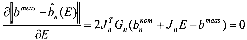
- This provides an updated version of the nominal model accounting for the difference between the measured field and the nominal model. The estimated position is found to be the position with the smallest difference, i.e. minimizing the residual: [10]

- The advantages of the above algorithm are:
- The algorithm makes use of constant tables that can be stored on the processor, i.e. it consists of


- In this example, the above algorithm is applied to a system with 24 axial displacements and with three ring-mounted sensors monitoring the magnet position.
- The dipole field model output is derived in each sensors position for magnet that is rotated to a position in 15° steps with 0.1488 mm axial displacement for each step. This can be stored in the system as the nominal model. An example of such a computer generated look-up table is shown in table 1 and illustrated in
figure 6A .Table : Example of look-up table of the nominal model Rod position Angular Pos. (Deg.) Axial Pos. (mm) Sensor 1 X Sensor 1 Y Sensor 1 Z Sensor 2 X Sensor 2 Y Sensor 2 Z Sensor 3 X Sensor 3 Y Sensor 3 Z 0 0 0.000 1.903 0.358 -0.414 0.122 -1.721 0.334 -0.788 0.861 0.080 1 15 0.149 2.057 0.067 -0.393 -0.234 -1.503 0.223 -0.447 1.266 0.170 2 30 0.298 2.072 -0.232 -0.342 -0.583 -1.168 0.116 -0.066 1600 0.226 3 45 0.446 1.940 -0.517 -0.272 -0.903 -0.736 0.023 0.328 1.835 0.248 4 60 0.595 1.666 -0.768 -0.192 -1.169 -0.239 -0.046 0.707 1.952 0.239 5 75 0.744 1.267 -0.968 -0.116 -1.169 -0.239 -0.046 0.707 1.952 0.239 6 90 0.893 0.766 -1.103 -0.052 -1.471 0.812 -0.088 1.041 1.939 0.204 7 105 1.042 0.198 -1.162 -0.008 -1.482 1.288 -0.086 1.480 1.518 0.095 8 120 1.190 -0.398 -1.1.41 0.010 -1.394 1.683 -0.051 1.549 1.134 0.041 9 135 1.339 -0.979 -1.041 0.002 -1.212 1.961 -0.004 1.057 0.664 0.002 10 150 1.488 -1.502 -0.870 -0.030 -0.946 2.110 0.046 1.357 0.139 -0.015 11 165 1.637 -1.928 -0.640 -0.080 -0.614 2.109 0.087 1.109 -0.403 -0.007 12 180 1.786 -2.226 -0.366 -0.138 -0.268 1.958 0.111 0.780 -0.925 0.027 13 195 1.934 -2.372 -0.067 -0.196 0.156 1.667 0.111 0.394 -1.390 0.085 14 210 2.083 -2.354 0.234 -0.241 0.542 1.257 0.082 -0.020 -1.763 0.159 15 225 2.232 -2.172 0.517 -0.265 0.892 0.756 0.023 -0.433 -2.017 0.242 16 240 2.381 -1.838 0.763 -0.259 1.182 0.201 -0.062 -0.814 -2.133 0.321 17 255 2.530 -1.376 0.954 -0.219 1.391 -0.367 -0.167 -1.137 -2.103 0.386 18 270 2.678 -0.819 1.079 -0.144 1.506 -0.909 -0.281 -1.378 -1.929 0.425 19 285 2.827 -0.208 1.128 -0.037 1.517 -1.385 -0.393 -1.522 -1.622 0.429 20 300 2.976 0.413 1.100 0.095 1.425 -1.760 -0.489 -1.558 -1.206 0.394 21 315 3.125 1.001 0.997 0.241 1.237 -2.010 -0.558 -1.486 -0.711 0.316 22 330 3.274 1.513 0.828 0.389 0.966 -2.119 -0.589 -1.312 -0.172 0.199 23 345 3.422 1.913 0.604 0.525 0.633 -2.079 -0.574 -1.051 0.372 0.049 figure 6B .Table 2: Example of measured sensor values for a given position and difference between measured and nominal model. Readings from sensors in current position 7 105 1.042 0.608 -1.032 -0.089 -1.073 1.419 -0.167 1.890 1.647 0.014 Difference between measured sensor values and Look-up table values: Rod position Angular Pos. (Deg.) Axial Pos. (mm) Sensor 1 X Sensor 1 Y Sensor 1 Z Sensor 2 X Sensor 2 Y Sensor 2 Z Sensor 3 X Sensor 3 Y Sensor 3 Z 0 0 0.000 1.295 1.390 -0.326 1.195 -3.140 0.501 -2.678 -0.786 0.066 1 15 0.149 1.450 1.099 -0.305 0.839 -2.922 0.391 -2.338 -0.381 0.156 2 30 0.298 1.464 0.800 -0.254 0.490 -2.586 0.283 -1.956 -0.047 0.212 3 45 0.446 1.332 0.515 -0.183 0.170 -2.155 0.191 -1.562 0.188 0.234 4 60 0.595 1.059 0.264 -0.104 -0.096 -1.658 0.121 -1.183 0.305 0.224 5 75 0.744 0.659 0.064 -0.027 -0.291 -1.129 0.079 -0.849 0.292 0.189 6 90 0.893 0.158 -0.071 0.037 -0.398 -0.607 0.067 -0.584 0.145 0.138 7 105 1.042 -0.410 -0.130 0.081 -0.409 -0.131 0.081 -0.411 -0.129 0.080 8 120 1.190 -1.006 -0.109 0.099 -0.322 0.264 0.116 -0.341 -0.513 0.027 9 135 1.339 -1.587 -0.009 0.090 -0.139 0.545 0.163 -0.383 -0.984 -0.012 10 150 1.488 -2.110 0.162 0.059 0.126 0.692 0.213 -0.533 -1.508 -0.030 11 165 1.637 -2.536 0.392 0.009 0.458 0.690 0.255 -0.781 -2.050 -0.022 12 180 1.786 -2.834 0.666 -0.050 0.834 0.539 0.279 -1.110 -2.572 0.013 13 195 1.934 -2.980 0.964 -0.107 1.229 0.248 0.278 -1.496 -3.037 0.070 14 210 2.083 -2.962 1.266 -0.152 1.615 -0.162 0.249 -1.910 -3.410 0.145 15 225 2.232 -2.780 1.549 -0.176 1.965 -0.663 0.190 -2.323 -3.664 0.228 16 240 2.381 -2.446 1.795 -0.170 2.255 -1.218 0.105 -2.704 -3.780 0.307 17 255 2.530 -1.984 1.986 -0.130 2.464 -1.786 0.000 -3.027 -3.750 0.372 18 270 2.678 -1.427 2.111 -0.055 2.579 -2.328 -0.114 -3.269 -3.576 0.411 19 285 2.827 -0.816 2.160 0.052 2.590 -2.804 -0.225 -3.412 -3.270 0.415 20 300 2.976 -0.194 2.132 0.184 2.498 -3.179 -0.321 -3.448 -2.853 0.380 21 315 3.125 0.393 2.029 0.330 2.309 -3.429 -0.390 -3.376 -2.358 0.302 22 330 3.274 0.905 1.859 0.478 2.039 -3.537 -0.421 -3.202 -1.819 0.185 23 345 3.422 1.305 1.636 0.614 1.705 -3.498 -0.407 -2.941 -1.275 0.035 - Then the Deviation parameters are derived by multiplication of Mn. This yields the En- vector for every position. These are listed in table 3.
- The deviations are bounded within configurable limits. For instance, Δϕ is bounded within ±7° to avoid that neighbouring positions overlap with the actual position. Furthermore, knowledge of the mechanical constraints of the magnet positions can also be applied at this point to rule out candidates when estimating the position.
Table 3: Estimated Deviation parameters for all positions Estimated deviation of system parameters for all positions Rod position Angular Pos. (Deg.) Axial Pos. (mm) Bext X Bext Y Bext Z Magnet position offset X Magnet position offset Y Magnet position offset Z Magnet moment offset Magnet angle offset Magnet tilt offset 0 0 0.000 -1.033 2.153 -0.172 0.283 0.959 -1.149 -2400.000 7.000 -3.517 1 15 0.149 0.327 1.602 -0.173 -0.013 1.000 -0.105 -2400.000 7.000 -3.704 2 30 0.298 1.151 1.661 -0.174 -0.254 0.967 0.368 -2400.000 7.000 -3.887 3 45 0.446 5.132 3.774 -0.175 -0.443 0.897 2.413 2400.000 7.000 -4.066 4 60 0.595 -1.274 -0.265 -0.177 0.585 -0.811 -0.902 -2400.000 7.000 -4.240 5 75 0.744 -0.120 0.207 -0.178 0.674 -0.739 -0.328 -2400.000 7.000 -4.407 6 90 0.893 0.245 0.161 -0.179 0.212 -0.372 -0.148 -625.788 7.000 -4.566 7 105 1.042 0.385 -0.346 -0.180 -0.992 -0.122 -0.073 -910.524 -0.345 -4.716 8 120 1.190 0.058 -0.539 -0.181 -0.957 -0.289 0.098 -1760.730 -7.000 -4.854 9 135 1.339 -19.517 -15.929 -0.182 -0.905 -0.425 0.227 -2400.000 7.000 -4.981 10 150 1.488 5.851 1.065 -0.183 0.774 0.633 0.515 -2400.000 -7.000 -5.000 11 165 1.637 16.559 -5.991 -0.184 0.576 0.817 2.520 -2400.000 -7.000 -5.000 12 180 1.786 -3.412 4.909 -0.184 -0.335 -0.942 -0.900 -862.746 -7.000 -5.000 13 195 1.934 -0.057 3.282 -0.185 -0.076 -0.997 -0.180 -2400.000 -7.000 -5.000 14 210 2.083 1.642 3.270 -0.185 0.181 -0.983 0.400 -2400.000 -7.000 -5.000 15 225 2.232 9.494 7.474 -0.186 0.424 -0.906 2.520 -2400.000 -7.000 -5.000 16 240 2.381 -3.054 -0.447 -0.186 -0.642 0.767 -2.468 -2400.000 -7.000 -5.000 17 255 2.530 -0.845 0.593 -0.186 -0.822 0.569 -1.489 -2400.000 -7.000 -5.000 18 270 2.678 -0.089 0.741 -0.186 -0.947 0.321 -1.345 -2400.000 -7.000 -5.000 19 285 2.827 0.413 0.236 -0.185 -0.364 -0.042 -1.773 -2400.000 -0.139 -5.000 20 300 2.976 0.848 1.136 -0.185 -0.978 -0.207 -1.226 -2400.000 7.000 -5.000 21 315 3.125 1.422 0.843 -0.184 -0.889 -0.457 -1.745 -2400.000 7.000 -5.000 22 330 3.274 2.528 0.353 -0.184 -0.748 -0.664 -2.520 -2400.000 7.000 -5.000 23 345 3.422 10.401 -3.830 -0.183 -0.568 -0.823 -2.520 2400.000 7.000 -5.000 fig. 7 showing the residual error between the updated version of the nominal model and the measured values.Table 4: Calculation of residuals between the updated version of the nominal model and measured values Readings from sensors in current position 7 105 1.042 0.608 -1.032 -0.089 -1.073 1.419 -0.167 1.890 1.647 0.014 Difference between measured sensor values and linearised corrected values: Rod position Angular Pos. (Deg.) Axial Pos. (mm) Sensor 1 X Sensor 1 Y Sensor 1 Z Sensor 2 X Sensor 2 Y Sensor 2 Z Sensor 3 X Sensor 3 Y Sensor 3 Z Sum of deviance: 0 0 0.000 -0.646 -3.104 0.122 -0.277 1.182 -0.159 3.309 -1.180 0.102 4.891 1 15 0.149 -1.584 -2.224 0.319 -1.081 1.351 -0.287 1.815 -0.784 0.016 3.813 2 30 0.298 -2.020 -2.066 0.366 -1.434 0.858 -0.216 0.859 -1.020 -0.107 3.621 3 45 0.446 -5.808 -3.920 0.942 -1.792 -1.622 -0.132 -3.245 -3.542 -0.768 9.963 4 60 0.595 -0.004 -0.064 -0.019 1.016 1.546 -0.079 1.953 -0.053 0.126 2.695 5 75 0.744 -0.647 -0.278 0.060 -0.069 0.806 -0.064 0.599 -0.207 0.012 1.249 6 90 0.893 -0.330 -0.057 0.023 -0.030 0.293 -0.018 0.124 -0.142 -0.004 0.485 7 105 1.042 -0.003 0.072 0.000 -0.006 0.090 -0.004 0.022 0.101 0.005 0.155 8 120 1.190 0.384 0.253 -0.009 0.065 0.228 -0.004 0.229 0.561 0.016 0.797 9 135 1.339 20.780 15.509 -0.042 19.116 15.344 -0.006 19.853 16.951 0.049 44.212 10 150 1.488 -3.753 -1.209 -0.088 -5.635 -1.368 0.042 -1.791 0.409 0.049 8.504 11 165 1.637 -14.243 5.508 -0.624 -16.683 5.530 0.584 -15.408 7.693 0.045 28.973 12 180 1.786 5.753 -5.197 0.383 2.503 -5.095 -0.395 4.244 -2.283 0.022 10.764 13 195 1.934 2.570 -3.782 0.214 -1.081 -2.976 -0.186 1.463 -0.182 -0.014 5.761 14 210 2.083 1.171 -4.055 0.101 -2.944 -2.719 -0.099 0.285 0.201 0.014 5.832 15 225 2.232 -6.587 -8.649 -0.436 -10994 -6.739 -0.062 -7.127 -3.862 0.517 18.725 16 240 2.381 4.908 -1.121 0.756 0.809 1.475 0.105 5.108 3.731 -0.837 8.335 17 255 2.530 2.359 -2.188 0.398 -1.664 1.149 0.291 3.235 2.959 -0.663 5.860 18 270 2.678 1.327 -2.332 0.244 -2.477 1.643 0.485 2.862 2.941 -0.701 5.802 19 285 2.827 0.373 -2.027 0.073 -2.725 2.487 0.712 2.734 2.915 -0.764 5.910 20 300 2.976 -0.657 -2.724 -0.155 -2.955 2.285 0.759 2.516 1.743 -0.571 5.665 21 315 3.125 -1.435 -2.393 -0.361 -3.128 2.468 0.890 1.907 1.466 -0.493 5.533 22 330 3.274 -2.716 -1856 -0.666 -3.839 2.632 1.002 0.577 1.307 -0.294 6.005 23 345 3.422 -11.383 2.182 -1.015 -11.606 7.081 1.004 -7.295 4.751 0.063 19.925 - From
fig. 7 , it is evident that the algorithm estimated the correct axial position of magnet, i.e.Rod position 7, axial position of 1.042 mm and rotational position of 105°. Table 5 states the deviations of system parameters for that position:Table 5: Deviation of system parameters for estimated position Estimated deviation of system parameters for estimated position Rod position Angular Pos. (Deg.) Axial Pos. (mm) Bext X Bext Y Bext Z Magnet position offset X Magnet position offset Y Magnet position offset Z Magnet moment offset Magnet angle offset Magnet tilt offset 7 105 1.042 0.385 -0.346 -0.180 -0.992 -0.122 -0.073 -910.524 -0.345 -4.716 - From the table, it is possible to evaluate the quality of the algorithm output. For example, the uniform external field is estimated to a have a magnitude of 0.55 Gauss (derived from the first three components). This is in the range of the earth's magnetic field. However, if this was estimated to be e.g. 2 Gauss, it would be more likely that the algorithm has estimated an incorrect position or that a large external field would be present.
- The magnet position has radial offset in the x-direction of -0.992 mm. If this is an unrealistic mechanical offset, an implemented system could be programmed to reject the algorithm output. Thus, if the fail-safe measures are not violated, the estimated position is considered a correct position.
- If the risk of external magnetic fields other than earth's magnetic field and disturbances in the internal magnetic field by the presence of iron nearby can be positively excluded, the most likely candidate of actual position found in the table can be relayed or displayed as actual position. However, in most applications the risk of disturbances in the magnetic field must be considered likely from a variety of sources and in some applications the consequences of a wrong determination of position could have serious and unacceptable consequences. In such applications a number of fail-safe measures can be taken, for example:
- (1) Taking a number of readings and use mean axis value from each axis from each sensor only when variations between readings are less than a predefined level. This could prevent wrong readings from the sensors caused by a fluctuating disturbance in the magnetic field.
- (2) Subtracting readings from diametrically opposite sensors to eliminate the magnet field contribution and the homogenous external field contribution and hence calculate the gradient of an inhomogeneous external field. Comparison against threshold values may be used as criteria for using the readings.
- (3) Using readings to calculate the external field. Comparison against threshold values may be used as criteria for using the readings.
- (4) Using readings from an over-determined sensor configuration to calculate deviations from pre-determined nominal mechanical geometry and magnet characteristics. Comparison against threshold values may be used as criteria for using the readings.
- (5) Comparing the deviance of the most likely position and the deviances of rejected positions (e.g. the second most likely position) to determine the credibility of the most likely position. Comparison against threshold values may be used as criteria for using the readings.
- (6) Comparing the most likely position and rejected positions, e.g. the top 10 next most likely positions, to determine the distribution of the positions. The distribution, e.g. span between minimum and maximum position, may be used as criteria for using the readings.
- (7) Using the most likely position to calculate the field contribution from the magnet and subtracting the contribution from the readings to obtain an estimated external field. The estimated external field may be used as input for calculating a most likely position which should be rejected by one or more of the fail-safe measures since the field contribution from the magnet has been eliminated. The field contribution from a position different from the most likely positions may be calculated and added to the estimated external field. The resulting field may be used as input for calculating a most likely position. Correspondence between the selected position and calculated position may be used as criteria for using the readings.
- (8) Using calculated positions to determine the mechanical movement, e.g. direction, speed and position stability. Comparison against threshold values may be used as criteria for using the readings.
- (9) Only appoint a most likely candidate of actual position if the minimum sum of deviance is less than a predefined value, to ensure a certain level of coherence between measured values and (expected) table values. This predefined value may be dependent on where in the range of operation the most likely candidate is, since the distances between neighboring candidates vary with distance from sensor. This should prevent a constant disturbance above a certain magnitude from causing the wrong position to be appointed most likely candidate and can also prevent a most likely candidate from being appointed if one of the sensors axis' have gone into saturated mode. If sensors are exposed to a magnetic field of a strength exceeding their limit of operation, they will go into saturation mode and give a readout of (a known predefined) maximum value.
- The above mentioned fail-safe measures will only be able to help prevent read-out of false positions by giving no position read-out at all. The system can then (if change of position is either prevented or monitored not to occur) repeat measurements until the system is clear of the external disturbance of the internal magnetic field. If change of position cannot be prevented, it can be monitored and the next successful read-out can be accompanied with a notification that current position is the sum of two (or more) individual movements. In some situations the system may be able to perform correct read-outs even if subjected to a disturbance in the internal magnetic field. Two such situations are described in the following.
- (10) If a very local disturbance occurs (as described above in point 3), typically caused by a small magnet or piece of iron very close to some of the sensors, it may be possible in some situations to get a valid reading instead of a fail-safe voided reading.
- (11) In some applications of such a system, the change of position between measurements is limited and in such application knowledge of prior position reading may help prevent false readouts of fail-safe situations. In disposable injection devices with the threaded rod connected to a reservoir piston, movement is only possible in one direction. Furthermore a dose pre-adjustment device limits each injection to a certain maximum travel of the tracing magnet. If a position measurement is performed after each injection, the most likely candidate found should be within the limited travel of the trace magnet or a disturbance must be assumed to have interfered with the measurement. The system can then either fail safely and not perform a read-out or find the second-most likely candidate, which is within the expected range. The validity should then be checked by use of a reduced threshold value of least sum of deviance (within valid range) and may be supplied by a coherence-check of the individual sensors best-fit values.
- Alternatively the limited allowable movement can be used to reduce the number of calculations and perform fewer table look-up operations, thereby increasing calculation speed and reducing power consumption.
- In
fig. 1 a further exemplary embodiment of a sensor assembly is configured as a number of sensors are placed along the line of movement. In the following a second exemplary algorithm for estimating a current position and orientation of a magnet will be described. - Each 3D magnetometer will measure with different off-sets in the three different directions and to compensate and adjust for the described embodiment, a reference magnet on a reference threaded rod is moved through the entire range of operation and readings of all axis' from all the sensors taken at small intervals of angular rotation of the threaded rod. All axis readings from all sensors are then offset and gain adjusted, so that maximum amplitude reached for each sensor is the same for all sensors and directions and they all fluctuate symmetrically around zero. This is illustrated in
figs. 8A and 8B showing sensor gain optimization, but only for one axis and two sensors to provide a better understanding through simplicity. -
Sensor 1 maximum amplitude: (S1Max - S1Min)/2 -
Sensor 2 maximum amplitude: (S2Max - S2Min)/2 - Maximum amplitude:
Sensor 1 maximum -
Sensor 1 gain: 1 -
Sensor 2 gain:Sensor 1 maximum amplitude/Sensor 2 maximum amplitude (>1) -
Sensor 1 off-set:Sensor 1 maximum amplitude -sensor 1 maximum -
Sensor 2 off-set:Sensor 2 maximum amplitude -sensor 2 maximum - To compensate for earth's magnetic field and other disturbing magnetic fields that influence the system with a uniform magnetic field, the axis value from one sensor is subtracted from the value of the value of the parallel axis of the neighboring sensor as illustrated in
fig. 9 showing subtraction of axis values between two sensors to compensate for earth's magnetic field and in which: - Dotted lines: Contributions from magnet
- Two-dots-one-line: Earth's magnetic field
- Broken line: Resulting vectors from sensors
- Long-short line: X-composants of resulting vectors
- Long-long: Z-composants of resulting vectors
- Full line: Resulting Difference vector
- Dotted lines represent distance/direction
- Full lines represent amplitude (Increasing with decreasing distance)
- Since the measured axis value in each direction for each sensor represents a vector representing direction and amplitude of the resulting magnetic field the sensor is subjected to, these vectors will represent the sum of the magnetic field of the tracing magnet and earth's magnetic field, which is depending on geographic location and orientation of the system relative to the surface of the earth. Since the contribution of earth's magnetic field must be considered uniform within the small area of the sensors, all sensors will be influenced by the same direction and amplitude from earth's magnetic field. By subtracting the axis values from each other between each sensor, the contribution of earth's magnetic field is cancelled out. This means that from a number (N) of sensors, there will be N-1 difference vectors as illustrated in
fig. 10 . - For a model corresponding to
fig. 1 with two axially arranged sensors, a piston rod was rotated from 0-150° and measurements were made for every 7.5° of rotation. The measurements listed below in tables 1 and 2 were made using an experimental set-up using Honeywell HMC5883L 3-axis magneto sensors. Based on this, a table of all axis values of all difference vectors for each measured angular (and thus linear) position can then be set up for the entire range of operation and stored in the system. An example of such a table is shown in table 1.Table 6: Example of look-up table of difference-vector axis' values and corresponding positions of a threaded rod Rod Postion ( x Angular Pos. (Deg.) Axial Pos. (mm) Sensor 1 X Sensor 1 Y Sensor 1 Z Sensor 2 X Sensor 2 Y Sensor 2 Z Difference 2-1 X Difference 2-1 Y Difference 2-1 Z 0 0,0 0,000 -155,9 143,2 295,9 -133,7 93,8 170,2 22,2 -49,4 -125,7 1 7,5 0,074 -156,6 143,5 295,9 -133,4 94,3 169,9 23,2 -49,2 -126,0 2 15,0 0,149 -156,7 144,2 295,1 -133,2 95,2 168,7 23,5 -49,0 -126,4 3 22,5 0,223 -156,6 143,8 294,5 -134,4 94,2 169,7 22,2 -49,6 -124,8 4 30,0 0,298 -156,1 144,3 294,0 -134,6 92,9 167,3 21,5 -51,4 -126,7 5 37,5 0,372 -156,4 143,4 293,7 -134,7 93,8 167,0 21,7 -49,6 -126,7 6 45,0 0,446 -156,9 143,4 293,2 -136,0 93,1 166,0 20,9 -50,3 -127,2 7 52,5 0,521 -157,2 142,8 293,3 -135,7 93,1 166,2 21,5 -49,7 -127,1 8 60,0 0,595 -157,3 142,7 293,3 -134,6 91,2 165,4 22,7 -51,5 -127,9 9 67,5 0,670 -157,0 142,6 293,9 -136,2 90,5 164,3 20,8 -52,1 -129,6 10 75,0 0,744 -156,6 142,2 293,0 -135,0 91,6 164,8 21,6 -50,6 -128,2 11 82,5 0,818 -156,4 141,6 293,4 -136,1 89,7 164,9 20,3 -51,9 -128,5 12 90,0 0,893 -156,5 140,8 293,4 -135,9 87,9 164,5 20,6 -52,9 -128,9 13 97,5 0,967 -156,8 141,3 293,4 -135,9 88,2 164,7 20,9 -53,1 -128,7 14 105,0 1,042 -156,6 140,2 292,7 -135,3 87,2 164,9 21,3 -53,0 -127,8 15 112,5 1,116 -156,8 139,5 293,4 -135,7 86,7 165,4 21,1 -52,8 -128,0 16 120,0 1,190 -156,9 139,9 293,0 -135,0 85,4 165,0 21,9 -54,5 -128,0 17 127,5 1,265 -156,1 140,5 293,2 -135,1 84,8 165,0 21,0 -55,7 -128,2 18 135,0 1,339 -155.7 139,2 293,1 -134,8 84,7 165,8 20,9 -54,5 -127,3 19 142,5 1,414 -156,0 139,5 293,0 -133,7 84,0 166,0 22,3 -55,5 -127,0 20 150,0 1,488 -155,6 138,5 293,0 -134,3 83,8 166,1 21,3 -54,7 -126,9 - When an actual (current) measurement is performed, all axis values are read from all sensors and the resulting difference-vector axis' values are calculated. Each of these calculated difference values are then subtracted from each of the corresponding table values for each sensor and the results from each axis and each sensor is added to each other for all table values of positions as shown in table 2.
Table 6: Example of look-up table of difference-vector axis' values and corresponding positions of a threaded rod Rod Postion ( x Angular Pos. (Deg.) Axial Pos. (mm) Sensor 1 X Sensor 1 Y Sensor 1 Z Sensor 2 X Sensor 2 Y Sensor 2 Z Difference 2-1 X Difference 2-1 Y Difference 2-1 Z 0 0,0 0,000 -155,9 143,2 295,9 -133,7 93,8 170,2 22,2 -49,4 -125,7 1 7,5 0,074 -156,6 143,5 295,9 -133,4 94,3 169,9 23,2 -49,2 -126,0 2 15,0 0,149 -156,7 144,2 295,1 -133,2 95,2 168,7 23,5 -49,0 -126,4 3 22,5 0,223 -156,6 143,8 294,5 -134,4 94,2 169,7 22,2 -49,6 -124,8 4 30,0 0,298 -156,1 144,3 294,0 -134,6 92,9 167,3 21,5 -51,4 -126,7 5 37,5 0,372 -156,4 143,4 293,7 -134,7 93,8 167,0 21,7 -49,6 -126,7 6 45,0 0,446 -156,9 143,4 293,2 -136,0 93,1 166,0 20,9 -50,3 -127,2 7 52,5 0,521 -157,2 142,8 293,3 -135,7 93,1 166,2 21,5 -49,7 -127,1 8 60,0 0,595 -157,3 142,7 293,3 -134,6 91,2 165,4 22,7 -51,5 -127,9 9 67,5 0,670 -157,0 142,6 293,9 -136,2 90,5 164,3 20,8 -52,1 -129,6 10 75,0 0,744 -156,6 142,2 293,0 -135,0 91,6 164,8 21,6 -50,6 -128,2 11 82,5 0,818 -156,4 141,6 293,4 -136,1 89,7 164,9 20,3 -51,9 -128,5 12 90,0 0,893 -156,5 140,8 293,4 -135,9 87,9 164,5 20,6 -52,9 -128,9 13 97,5 0,967 -156,8 141,3 293,4 -135,9 88,2 164,7 20,9 -53,1 -128,7 14 105,0 1,042 -156,6 140,2 292,7 -135,3 87,2 164,9 21,3 -53,0 -127,8 15 112,5 1,116 -156,8 139,5 293,4 -135,7 86,7 165,4 21,1 -52,8 -128,0 16 120,0 1,190 -156,9 139,9 293,0 -135,0 85,4 165,0 21,9 -54,5 -128,0 17 127,5 1,265 -156,1 140,5 293,2 -135,1 84,8 165,0 21,0 -55,7 -128,2 18 135,0 1,339 -155.7 139,2 293,1 -134,8 84,7 165,8 20,9 -54,5 -127,3 19 142,5 1,414 -156,0 139,5 293,0 -133,7 84,0 166,0 22,3 -55,5 -127,0 20 150,0 1,488 -155,6 138,5 293,0 -134,3 83,8 166,1 21,3 -54,7 -126,9 

- The lowest sum of deviance can now be determined and the corresponding position of the threaded rod is considered most likely candidate for the actual position of the threaded rod. This method will in effect ensure that the difference values from the sensor-pair(s) closest to the actual position of the tracing magnet will be the determining sensors, since the amplitude of the signal from these sensors will be orders of magnitudes higher than the sensor further from the tracing magnet. As appears, it was possible to identify the correct position although the measured values were not 100% identical to those stored in the look-up table.
- The contribution to the sum of deviance from the closest sensors will thus increase significantly on each side of the correct value and by far overrule if the contribution to the sum of deviance from some of the sensors further away should have a minimum elsewhere. This is illustrated in
figs. 11A and 11 B where the poorer signal-to-noise ratio for the sensor furthest from the trace magnets actual position leads to a minimum contribution to the sum of deviance on a position other than the actual position. Infig. 11A the position of the magnet corresponds to a drug delivery system of the traditional pen-type in which 35 units of drug has been expelled from a cartridge comprising 300 units of drug.Fig. 11 B illustrates corresponding measurements when 200 units have been expelled. - For an exemplary application of the invention in a drug delivery system for detection of expelled amounts of drug the following considerations are relevant. Firstly, the drug delivery system should comprise a component which is moved both axially and rotationally during an operation associated with the expelling of a dose of drug. Such a system could be a pen-formed drug delivery device in which a piston rod corresponding to a set dose is moved both axially and rotationally to move the piston of a drug-filled cartridge forwards to thereby expel the set dose of drug there from, this corresponding to the above-described two examples.
- An example of such a drug delivery device is FlexTouch® from Novo Nordisk. When provided with a 3 ml Penfill® cartridge containing a 100 IU/ml insulin formulation the FlexTouch® device is set to axially move forward the piston rod 0.1488 mm for each IU to be expelled, this corresponding to 15° of rotation of the piston rod. Thus, in order to provide a measuring system configured to detect the position of the piston rod with a precision corresponding to 0.5 IU it should be possible to detect the axial position with a precision corresponding to 7.5° of rotation of the piston rod.
- As indicated, the above-described exemplary systems have been set up for application in a drug delivery system. Correspondingly, in the following a number of different configurations for a combined system comprising a pen-formed drug delivery device (e.g. a FlexTouch® or a FlexPen® from Novo Nordisk, see e.g.
US 6,004,297 which is hereby incorporated by reference) and a measuring system for detection of an out-dosed amount of drug will be described. As FlexTouch® and FlexPen® are pre-filled drug delivery pens designed to be disposed off when the drug cartridge has been emptied, the measuring system is provided as a re-useable durable add-on system/unit adapted to be used in combination with a corresponding pen, i.e. the pen comprising a small magnet mounted distally on the piston rod and coupling means allowing the measuring magnetometers to be positioned in a pre-determined position relative to the piston rod. In order to determine an amount of drug expelled, the position of the piston rod before and after an expelling action is detected, the difference there between corresponding to the axial displacement of the piston rod during out-dosing of a given amount of drug and thus the axial displacement of the piston in the cartridge. From the axial distance travelled by the piston rod an amount of drug can be calculated (e.g. each 0.1488 mm of travel representing 1 IU of insulin) and communicated to the user and/or stored in a memory together with other data such as time and date. - Turning to
figs. 12A-12D a measuring system is shown configured as a two-unit assembly comprising a measuringunit 101 and adisplay unit 110, the measuring unit being adapted to be mounted on adrug delivery pen 120 for the life of the pen for thereafter being transferred to a new pen, the display unit being configured as a cap adapted to cover the needle mount (and aneedle assembly 122 if mounted) and thus adapted to be removed prior to administration of a dose of drug and re-mounted after the administration. Correspondingly, the positions of the piston rod when the cap is removed respectively attached again can be used to calculate an expelled dose of drug which is then shown together with a time stamp on the display unit. Indeed, if the cap is left off between two dosing events then a combined dose will be registered. However, as this would be associated with a long period of time between two measurements the processor could be programmed to provide a warning if the cap has been left off for a period of time longer than necessary for the administration of a dose of drug, e.g. 5 minutes. In the shown embodiment thedisplay unit 110 comprises amatrix LCD 114, processor, timer and memory means 112 as well as the systemmain batteries 115, e.g. 2 x CR1225, which is used to charge smallersecondary batteries 105 housed in the measuring unit. The measuring unit comprises 53D magnetometers 107 as well as supportingelectronic components 102 allowing magnetic data capture and storage thereof until data can be transmitted to the cap unit for further processing viagalvanic contacts ring 108 adapted to engage the standard cap coupling means provided on a FlexTouch® pen, however, in order to secure a safe and secure mounting the coupling components on the mounting ring may be designed to provide a firmer grip than a standard cap. - By designing the sensor ring to be mounted on the pen in a rotating motion, a scenario in which the sensor system is rotated relative to the magnet in a fixed position is present. This could be used to adjust e.g. sensor offset- and gain-values by detecting maximum measurements during mounting of sensor ring on pen. The system could then be calibrated to the actual pen and any look-up table then be adjusted to compensate for any rotational offset in magnet or rod orientation to increase accuracy and reliability.
-
Figs. 13A-13C show an alternative embodiment of a two-unit measuring assembly. In contrast to thefig. 9 embodiment all components apart from themain battery 215 is located in a ring-formedmeasuring unit 201 which then also comprises thedisplay 204 which in the shown embodiment is of the e-ink type. As for the first embodiment, removal and re-attachment of the cap can be used to define a dosing event. -
Figs. 14A and 14B show a further embodiment in which all of the above-described measuring and display components are arranged in aunitary cap unit 301, comprising adisplay 304, all theelectronics 302, and thebatteries 305. In addition to the above described components, this embodiment comprises anoptical reader 309 adapted to capture information provided for a given drug cartridge. - For all of the above embodiments, communication means may be provided allowing wired or wireless transfer of data, e.g. upload of measured data to a PC or smartphone, or download of new software.
- In the above embodiments for a measuring system adapted for use with a pre-filled drug delivery device have been described, however, the same systems could be used in combination with a durable drug delivery device adapted to be re-loaded with a new cartridge when a first has been used, and which comprises e.g. a piston rod rotating during axial displacement. Indeed, for a durable device the components of the measuring system could be fully or partly integrated in the device.
- As a further alternative the measuring system could be incorporated in a
docking station 401 intended for stationary use with apen 410 as shown infig. 15 . Such an arrangement may be relevant for users in need of e.g. a single daily dose of drug, e.g. in the morning or at bedtime, for which purpose the drug delivery device could be placed in the docking station during the day and only be removed there from for a short period of time when the daily dose is to be taken. - As appears from the above, the size of a dose of drug is based on the determination of two piston rod positions, however, this requires that the two positions are determined for the same device and not for two different devices which could be the case, especially if the measuring system is in the form of a unitary cap device which easily by mistake could be reattached to a wrong drug delivery device, or a docking station in which a "wrong" pen may be positioned. To prevent such un-intended pen shifts, the drug delivery device (or cartridge) could be provided with a unique identifier adapted to be recognized by the measuring device, e.g. a 2D matrix code on the cartridge and an optical reader in the cap or docking station. For embodiments comprising a "semi-fixed" measuring and memory unit (e.g. as in
figs. 13A-13C ) each attachment to a drug delivery device could prompt the unit into a "new device" mode. In case the processor and memory is provided in the cap unit (e.g. as infigs. 12A-12C ) the two units of a given system could be paired and programmed to only work in combination. A more detailed description of means for capturing an identifier is given below with reference tofigs. 16-18 . - In
figs. 12-15 embodiments are shown utilizing conventional electronics design, however, alternatively printed electronic circuits could be implemented to fully or partly replace conventional circuit technology. Printed electronic is based on standard printing technologies, using different types of ink materials to build electronic circuits and components by printing different patterns in different materials in a number of layers. Inks are made from organic and inorganic materials as well as substrates, depending on purpose. Organic materials are mainly conjugated polymers which possess conducting, semiconducting, electroluminescent, photovoltaic and other properties. Inorganic materials (based on metals such as silver particles, gold particles, aluminium particles, copper doped phosphor) are used for higher order layers and interfaces that organic and polymer materials cannot provide. Substrates such as Polyethylene terephthalate-foil (PET), Polyethylene naphthalate foil (PEN) and Polyimide foil (PI) are used as a carrier to print the electronics on for later transfer to end product. Paper can also be used to some extent. - By printing a number of layers of different patterns and materials, an electronic circuit with conductive leads and components as well as a power source (battery), energy harvesters and display can be created. These materials and processes are now commercially available. Since most of disposable drug delivery devices are made of plastic materials, electronics may be printable directly to the surface of the components with no need of a carrying substrate. When a device is to be fitted with more advanced sensors and functionality as the shown volume detection systems, the display unit and to some extend some of the necessary electronic circuitry can be based on printed electronics. By printing the electronic circuits, sensors, power source, components and display on the injection devices, the added features will have little or no impact on the physical size and design requirements of the injection device, thereby significantly improving marketing ability. Furthermore, printing the electronics will enable significantly reduced production costs compared to traditional electronic circuits, since production can be performed more efficient and material use is greatly reduced.
- If the drug delivery device is provided with a spring tensioned during dose setting, e.g. a FlexTouch® pen, an adjusted dose detection system may be realized by measuring the change in magnetic field of the tensioning of the drive spring in the expelling mechanism with the magnetometer nearest the spring.
- Further, when using a magnetometer based volume detection system, a small error of measurement may occur if the sensor system determines remaining volume while the user is still actuating the release button of e.g. a FlexTouch® pen. When the release button is actuated, the drive spring moves slightly in the axial direction. By detecting the small change in axial direction of the spring, e.g. of the distal spring "hook" by using the magnetometer sensors, the system can avoid measuring remaining volume in the reservoir while the release button is actuated.
- As an alternative to the above-described embodiments a simple volume/ dose-detection system could be made using a number of simple one-dimensional magnetometers along the side of a pen reservoir and have a small magnet built-in to the piston rod. The system could determine the position of the piston rod simply by detecting which magnetometer(s) give the most signal. Such a concept would be simple, however, it may be sensitive to disturbing external fields and may require a large number of sensors to meet requirements of accuracy.
- Electronic identification systems can be divided into two groups, type identifiers and unique identifiers, where type identifiers are able to only identify the type of device or contents but are not able to distinguish between two identical devices of the same type. The unique identifiers are able to not only identify the type of device and contents but also the unique identity of a device and thus able to distinguish two identical devices from each other.
-
Figs. 16A-16E show an embodiment of a measuringunit 601 of the semi-fixed type adapted to be attached to a pre-filled pen-formeddrug delivery device 610 for the operational life time of the device, i.e. until the drug reservoir (cartridge) has been emptied. The drug delivery device may be of a type corresponding to e.g. a FlexTouch® or a FlexPen® from Novo Nordisk. The pen is provided with an identifier corresponding to the specific drug content in the reservoir, and the measuring unit as provided with means for capturing this information. More specifically, the pen body is provided with one ormore protrusions 611 creating a simple code corresponding to the contained drug, e.g. a long-actinginsulin 100 IU/ml, a long-actinginsulin 200 IU/ml, a fast-actinginsulin 100 IU/ml or a fast-actinginsulin 200 IU/ml. The measuring unit is provided with a number ofcorresponding contacts 603 adapted to be activated by the protrusions when the unit is mounted on the pen body as shown infigs. 16A and 16B . -
Figs. 16C-16E shows 3 examples of code patterns. The measuring unit may be adapted to detect when a cap (not shown) is taken off and mounted again, this initializing two measurements of the piston position on the basis of which an expelled dose amount can be calculated. -
Fig. 17 shows an embodiment of a measuring unit in the form of acap unit 701 adapted to be attached to a pre-filled pen-formeddrug delivery device 710 when the device is not in use. The drug delivery device may be of a type corresponding to e.g. a FlexTouch® or a FlexPen®. As appears, for the internal parts of the device only thedrug cartridge 712 and the piston rod are shown. The pen is provided with an identifier in the form of a coloured cartridge holder corresponding to the specific drug content in the reservoir, e.g. orange for a fast-actinginsulin 100 IU/ml and green for a long-actinginsulin 100 IU/ml, and the measuring unit as provided with means for capturing this information. More specifically, the measuring unit is provided with awhite LED 702 is fitted in such a way, that it will enlighten the colour-coded part of the pen, as well as an RGB-sensor chip 703 fitted in such a way, that the area enlightened by the white LED is visible to the RGB-sensor. A shielding to prevent the RGB-sensor to be exposed to direct light from the white LED is arranged between the two. In the figure the remaining electronic components of the cap are not shown. When the light from the white LED containing all colours hits the coloured surface only light with the same colour as the part is reflected to the RGB-sensor, this allowing the RGB composition of the reflected light to be analysed and the colour and thereby type of pen and drug identified. The cap unit may be adapted to detect when the cap unit taken off and mounted again on the pen body, this initializing a measurement of the piston position when the cap is mounted on the basis of which an expelled dose amount can be calculated, i.e. the position for the previous use of the device has been stored. The cap unit may be programmed to work with only one type of pen, i.e. one colour, or with two or more different types of pens. In the latter case the cap unit may be used with only one type of pen at a time, or it may be used with e.g. two types of pens at a time, this being relevant for diabetics using both long-acting and fast-acting insulin. As the colour typically will be detected each time the pen is activated, the pen may automatically detect whether a dose has been expelled or a shift of device has taken place. -
Figs. 18A-18E show an embodiment of a measuringunit 801 of the semi-fixed type adapted to be attached to a pre-filled pen-formeddrug delivery device 810 for the operational life time of the device, i.e. until the drug reservoir (cartridge) has been emptied. The drug delivery device may be of a type corresponding to e.g. a FlexTouch® or a FlexPen®. The pen is provided with an identifier in the form of a 2D barcode in printed electronic leads corresponding to the specific drug content in the reservoir, and the measuring unit as provided with a correspondingcapacitive fingerprint reader 803 for capturing this information. - There are basically two different scanner technologies available, optical scanners and capacitive scanners. Capacitive scanners are well suited for pen identification since they can be made very small and compact and requires very little power compared to optical scanners. A capacitive fingerprint scanner in principal consists of one or more semiconductor chips containing a line or an array of small cells, each cell including two conductive plates covered by an isolating layer and being smaller than the ridges and valleys of the skin on a finger. Each cell is connected to a small electrical circuit with an inverting operational amplifier, a so called integrator. Prior to scanning the reset switch is closed applying an input reference voltage to both conductor plates which shorts the amplifiers in- and out-puts and "balances" the integrator circuit. When the Reset switch is opened again the processor applies a fixed charge to the integrator circuit. If any capacitive object is placed close the conductive plates (normally the skin of a finger) the capacitance of the system will change and since one of the conductive plates are connected to the inverting terminal, the amplifiers input will change and subsequently the amplifier output will change. By substituting the ridges and valleys of the skin in a fingerprint with a pattern of small conductive leads printed on the pen (or a carrier foil fitted on the pen) the small cells can detect if a printed lead is present below the insulating layer of the conductor plates or not. Due to the size of these small cells a large number of cells can be fitted in a small area and thus large quantities of information can be stored and read on a small area, allowing for long serial-numbers to be identified. Such a serial-"pattern" will be difficult to counterfeit since not only the pattern but also the capacitive properties has to be correct. Next it will be described how such a system could be implemented on a pen with the electronic dose detection unit comprising a capacitive fingerprint line scanner.
- A
capacitive fingerprint reader 803 is incorporated in anelectronic unit 802 for dose detection in such a way, that when the electronic measuring unit is slid onto the pen 810 atap 812 on the pen ensures that the fingerprint reader is clear of the2D barcode 811 printed in electronic leads on a foil and placed behind the tap on the pen. When the tap meets the mountingring 807 of the measuring unit and cannot move any further, the user can start rotate the unit to secure it to the pen. When rotation begins the tap enters atrack 806 which guides the unit to perform a rotational movement without sliding along the axis of the pen. During the rotation the fingerprint scanner reads the 2D code on the pen line by line and when the unit is secured to the pen the electronics in the unit will have identified exactly what pen and type the electronic measuring unit is fitted on and be able to give read-outs of actual dose and type instead of just the detected volume of the dose. - Alternatively, a simple optical barcode-reader could be implemented using the mounting of the electronic unit on the pen to perform the sweep and use a simple, low-power LED as light source. However, a barcode based on simple reflection of light from an LED will require relatively wide bars and spacing and thus result in physically long barcodes compared to barcodes based on laser reading. Therefore such a system would mainly be applicable on larger units where one part is mounted on the other with a sufficient long sliding- or rotational movement to cover the necessary number of digits in the barcode.
- A unique identification system could also be based on a NFC ID-chip and a build-in chip-reader in the electronic unit. This technology is commonly known and widely used for such purposes, however, for a disposable drug delivery device it may be more expensive than the above-described embodiment based on a fingerprint reader.
- When information in respect of a specific type of drug has been identified, this information could also be used to provide a user with further information. By reading the code the unit becomes aware of the drug type and could inform the user of necessary actions say just before an injection or just after an injection. Furthermore, the information of the drug could be stored in the electronic unit and transferred to an external device, e.g. a Personal Computer (PC) or a mobile phone. The external device could then display the information and thus act as a display for the electronic unit which may be provided with only a simple numeric display. The information of the drug could also be stored on a server, and the electronic unit could send the unique code to the external device. The external device would then retrieve the drug specific information from the server using the unique code. This drug-identifying functionality could also be incorporated in an electronic drug delivery device per se not related to a dose detecting unit.
- In the above description of exemplary embodiments, the different structures and means providing the described functionality for the different components have been described to a degree to which the concept of the present invention will be apparent to the skilled reader. The detailed construction and specification for the different components are considered the object of a normal design procedure performed by the skilled person along the lines set out in the present specification.
Claims (11)
- A system for detecting an axial position of a threaded piston rod of a drug injection device, the system comprising:- a sensor assembly (4) comprising one or more sensors each adapted to measure a magnetic field corresponding to three axes, a moveable element (1),- a magnet (3) mounted to the moveable element and moving together therewith, the magnet configured to generate a spatial magnetic field which relative to the sensor assembly varies corresponding to both the axial and rotational movement of the magnet and thus the moveable element, thereby generating a spatial magnetic field which varies uniquely relative to each sensor, and- processor means (5) configured to determine on the basis of measured values an axial position of the moveable element,
characterized in that- each sensor is adapted to measure a magnetic field corresponding to three axes arranged perpendicularly relative to each other,- the moveable element such as said threaded piston rod (1) being adapted to be moved relative to the sensor assembly by a combined axial and rotational movement corresponding to a pre-defined axis, the rotational movement having a pre-determined relationship to the axial movement, and- the processor means, on the basis of the measured values, is adapted to:- determine an initial axial position of the moveable element,- determine a rotational position of the moveable element, and- calculate a corrected axial position of the moveable element,wherein the calculation is based on the determined initial axial position, the determined rotational position, and the pre-determined relationship between the rotational and the axial movement. - A system as in claim 1, wherein the sensor assembly is configured as one or more rings each consisting of two or more sensors placed around the pre-defined axis.
- A system as in claim 1 or 2, wherein the magnet is an induced magnet.
- A system as in any one of the proceeding claims, wherein the moveable element is moved corresponding to a threaded relationship between the moveable element and a further element.
- A system as in any one of the proceeding claims, comprising a drug delivery device (120) comprising:- a reservoir or means for receiving a reservoir for a drug (121), the reservoir comprising an axially displaceable piston and an outlet (122), and- a drug expelling mechanism for expelling drug from the reservoir and comprising the moveable element in the form of a threaded piston rod which during an expelling action performs the combined axial and rotational movement thereby axially moving the piston of a mounted reservoir.
- A system as in claim 5, comprising a measuring unit (301, 401) in which the sensor assembly (307) and processor means (302) are arranged, and which is configured to receive the drug delivery device in a pre-determined position, the measuring unit being configured to calculate the size of an expelled dose of drug based on two consecutive determinations of the axial position of the piston rod.
- A system as in claim 6, wherein the measuring unit is in the form of a cap unit adapted to calculate the size of an expelled dose of drug when the cap unit is placed in its mounted position on the drug delivery device to cover the outlet (122) of a mounted reservoir.
- A system as in claim 5, comprising a measuring assembly in which the sensor assembly and processor means are arranged, the measuring assembly comprising a measuring unit (101, 201) and a cap unit (110, 210),- wherein the measuring unit comprises the sensor assembly (107, 207) as well as coupling means (108, 208) allowing the measuring unit to be mounted on the drug delivery device with the sensor assembly in a pre-determined position relative to the piston rod, and- wherein the cap unit is configured to be releasably mounted on the drug delivery device or the measuring unit to cover the outlet (122) of a mounted reservoir.
- A system as in any one of claims 5-8, comprising a display (114, 204, 304) controlled by the processor means to display a calculated dose of drug.
- A system as in any one of claims 6-9, the drug delivery device further comprising:- an identifier representing information for the specific drug type contained in the reservoir or the specific drug delivery device,the measuring unit further comprising:- means for capturing information from the identifier, and- logging means adapted to create a log for amounts of drug expelled from the reservoir based on calculated doses of drug, the log being created for a given identifier.
- A system as in claim 10, wherein the identifier is a colour, in the form of a barcode, or in the form of a pattern of conductive elements.
Priority Applications (1)
| Application Number | Priority Date | Filing Date | Title |
|---|---|---|---|
| EP12768850.5A EP2763722B1 (en) | 2011-10-07 | 2012-10-05 | System for determining position of element based on three-axial magnetic sensors |
Applications Claiming Priority (4)
| Application Number | Priority Date | Filing Date | Title |
|---|---|---|---|
| EP11184280 | 2011-10-07 | ||
| US201161545693P | 2011-10-11 | 2011-10-11 | |
| EP12768850.5A EP2763722B1 (en) | 2011-10-07 | 2012-10-05 | System for determining position of element based on three-axial magnetic sensors |
| PCT/EP2012/069729 WO2013050535A2 (en) | 2011-10-07 | 2012-10-05 | System for determining position of element |
Publications (2)
| Publication Number | Publication Date |
|---|---|
| EP2763722A2 EP2763722A2 (en) | 2014-08-13 |
| EP2763722B1 true EP2763722B1 (en) | 2016-08-10 |
Family
ID=48044240
Family Applications (1)
| Application Number | Title | Priority Date | Filing Date |
|---|---|---|---|
| EP12768850.5A Active EP2763722B1 (en) | 2011-10-07 | 2012-10-05 | System for determining position of element based on three-axial magnetic sensors |
Country Status (5)
| Country | Link |
|---|---|
| US (1) | US10155090B2 (en) |
| EP (1) | EP2763722B1 (en) |
| JP (1) | JP6109834B2 (en) |
| CN (1) | CN103957961B (en) |
| WO (1) | WO2013050535A2 (en) |
Cited By (1)
| Publication number | Priority date | Publication date | Assignee | Title |
|---|---|---|---|---|
| CN110715605A (en) * | 2019-10-18 | 2020-01-21 | 阳光电源股份有限公司 | Method, device and system for detecting running position of photovoltaic module cleaning robot |
Families Citing this family (170)
| Publication number | Priority date | Publication date | Assignee | Title |
|---|---|---|---|---|
| US7959598B2 (en) | 2008-08-20 | 2011-06-14 | Asante Solutions, Inc. | Infusion pump systems and methods |
| EP2763722B1 (en) | 2011-10-07 | 2016-08-10 | Novo Nordisk A/S | System for determining position of element based on three-axial magnetic sensors |
| TWI471764B (en) * | 2012-02-20 | 2015-02-01 | Qisda Corp | Coordinate sensing system, coordinate sensing method and display system |
| EP4406568A3 (en) | 2012-03-30 | 2024-10-16 | Insulet Corporation | Fluid delivery device with transcutaneous access tool, insertion mechanism and blood glucose monitoring for use therewith |
| HK1211507A1 (en) * | 2012-08-10 | 2016-05-27 | Sanofi-Aventis Deutschland Gmbh | Pen-type drug injection device and electronic add-on monitoring module for monitoring and logging dose setting and administration |
| US9897565B1 (en) | 2012-09-11 | 2018-02-20 | Aseko, Inc. | System and method for optimizing insulin dosages for diabetic subjects |
| US9171343B1 (en) | 2012-09-11 | 2015-10-27 | Aseko, Inc. | Means and method for improved glycemic control for diabetic patients |
| EP2740514B1 (en) * | 2012-12-04 | 2017-04-05 | BIOTRONIK SE & Co. KG | Implantable electrostimulation arrangement and adapter and alectrode lead of the same |
| DE102013000431A1 (en) | 2013-01-14 | 2014-07-17 | Micronas Gmbh | Circuit and measuring system |
| DE102013000430A1 (en) | 2013-01-14 | 2014-07-17 | Micronas Gmbh | measuring system |
| DE102013000432A1 (en) * | 2013-01-14 | 2014-07-17 | Micronas Gmbh | measuring system |
| CN105007964B (en) * | 2013-02-19 | 2018-01-30 | 诺和诺德股份有限公司 | Dosage for doser captures cylinder mould block |
| US10105497B2 (en) | 2013-04-05 | 2018-10-23 | Novo Nordisk A/S | Drug delivery device with integrated magnetic movement indicator |
| WO2014161952A1 (en) | 2013-04-05 | 2014-10-09 | Novo Nordisk A/S | Dose logging device for a drug delivery device |
| JP2016517720A (en) | 2013-04-05 | 2016-06-20 | ノボ・ノルデイスク・エー/エス | Logging device for adding multiple doses |
| EP2988801B1 (en) * | 2013-04-22 | 2019-02-20 | Sanofi-Aventis Deutschland GmbH | Sensor device for attachment to a drug delivery device |
| DK2988806T3 (en) * | 2013-04-22 | 2022-07-18 | Sanofi Aventis Deutschland | SUPPLEMENTARY DEVICE FOR USE WITH AN INJECTION DEVICE |
| EP2988803B1 (en) * | 2013-04-22 | 2017-08-16 | Sanofi-Aventis Deutschland GmbH | A supplementary device for a manually operable injection device |
| EP2994179B1 (en) * | 2013-05-07 | 2018-03-14 | Sanofi-Aventis Deutschland GmbH | A supplemental device for attachment to an injection device |
| US9561324B2 (en) | 2013-07-19 | 2017-02-07 | Bigfoot Biomedical, Inc. | Infusion pump system and method |
| WO2015032715A1 (en) * | 2013-09-03 | 2015-03-12 | Sanofi-Aventis Deutschland Gmbh | Drug delivery device comprising a cap sensor and a radiation sensor |
| EP3071262B1 (en) | 2013-11-21 | 2020-04-08 | Novo Nordisk A/S | Rotary sensor assembly with space efficient design |
| CN105764550B (en) | 2013-11-21 | 2019-12-24 | 诺和诺德股份有限公司 | Rotary Sensor Assembly with Axial Switch and Redundancy Features |
| US9907902B2 (en) * | 2013-12-20 | 2018-03-06 | Maxim Integrated Products, Inc. | Precise accurate measurement of the administration of drugs using the injection method by means of ultrasonic pulse-echo principles |
| WO2015098399A1 (en) * | 2013-12-27 | 2015-07-02 | パナソニックヘルスケアホールディングス株式会社 | Drug administration device and method for controlling drug administration device |
| US9486580B2 (en) | 2014-01-31 | 2016-11-08 | Aseko, Inc. | Insulin management |
| US9233204B2 (en) | 2014-01-31 | 2016-01-12 | Aseko, Inc. | Insulin management |
| US20150246179A1 (en) * | 2014-03-02 | 2015-09-03 | Nissim Zur | Device and method for drug dosing with administration monitoring, in particular for insulin pen integrated with smart phone apps. |
| US20170124285A1 (en) | 2014-06-03 | 2017-05-04 | Amgen Inc. | Devices and methods for assisting a user of a drug delivery device |
| EP3151880B1 (en) * | 2014-06-06 | 2018-05-16 | Novo Nordisk A/S | Logging device for drug delivery device |
| US10183119B2 (en) | 2014-06-06 | 2019-01-22 | Novo Nordisk A/S | Logging device operated by drug delivery device |
| US11083838B2 (en) * | 2014-07-21 | 2021-08-10 | Medtronic Minimed, Inc. | Smart connection interface |
| US10387701B2 (en) * | 2014-07-31 | 2019-08-20 | The Code Corporation | Barcode reader and docking station for charging the barcode reader |
| CN106573115B (en) * | 2014-08-25 | 2019-12-24 | 诺和诺德股份有限公司 | Attachment with snap-fit feature |
| MX2017002759A (en) | 2014-09-02 | 2017-05-09 | Lilly Co Eli | Sensing system for detecting a piston in a medical fluid container. |
| US10704944B2 (en) | 2014-09-14 | 2020-07-07 | Becton, Dickinson And Company | System and method for capturing dose information |
| US10971260B2 (en) | 2014-09-14 | 2021-04-06 | Becton, Dickinson And Company | System and method for capturing dose information |
| EP3200854B1 (en) * | 2014-10-03 | 2020-01-08 | Novo Nordisk A/S | Pen-type drug injector and add-on module with magnetic dosage sensor system and error detection |
| CA2927335C (en) | 2014-10-27 | 2023-05-02 | Aseko, Inc. | Subcutaneous outpatient management |
| US11081226B2 (en) | 2014-10-27 | 2021-08-03 | Aseko, Inc. | Method and controller for administering recommended insulin dosages to a patient |
| CN107405453B (en) | 2015-03-06 | 2020-12-04 | 赛诺菲-安万特德国有限公司 | Sensor assembly for injection device |
| EP3075404A1 (en) * | 2015-03-30 | 2016-10-05 | Carebay Europe Ltd. | Information provider assembly to be used with a medicament delivery device |
| US10772520B2 (en) * | 2015-06-25 | 2020-09-15 | DePuy Synthes Products, Inc. | Intraoperative magnetometry monitoring system |
| ES2964787T3 (en) * | 2015-07-21 | 2024-04-09 | Biocorp Production SA | Dose control device for injectable drug delivery devices |
| EP3419699B1 (en) * | 2015-07-21 | 2023-06-07 | Biocorp Production S.A. | Dose control system for injectable-drug delivery devices and associated methods of use |
| DE102015213806A1 (en) * | 2015-07-22 | 2017-01-26 | Volkswagen Aktiengesellschaft | Position determination with a magnetic field sensor for a vehicle |
| JP7005484B2 (en) * | 2015-07-29 | 2022-01-21 | サノフィ-アベンティス・ドイチュラント・ゲゼルシャフト・ミット・ベシュレンクテル・ハフツング | Sensor device for drug delivery device |
| JP6873971B2 (en) | 2015-07-31 | 2021-05-19 | サノフィ−アベンティス・ドイチュラント・ゲゼルシャフト・ミット・ベシュレンクテル・ハフツング | Sensors for drug delivery devices |
| WO2017021227A1 (en) | 2015-07-31 | 2017-02-09 | Sanofi-Aventis Deutschland Gmbh | Sensor, cartridge and drug delivery device |
| EP3328467B1 (en) | 2015-07-31 | 2022-03-23 | Sanofi-Aventis Deutschland GmbH | Sensor, cartridge and drug delivery device |
| JP6862418B2 (en) | 2015-07-31 | 2021-04-21 | サノフィ−アベンティス・ドイチュラント・ゲゼルシャフト・ミット・ベシュレンクテル・ハフツング | Sensors, cartridges, and drug delivery devices |
| CN105158708A (en) * | 2015-08-19 | 2015-12-16 | 深圳市沃特沃德科技有限公司 | Mobile intelligent terminal capable of detecting dynamic magnetic field and detection method of mobile intelligent terminal |
| US9886556B2 (en) | 2015-08-20 | 2018-02-06 | Aseko, Inc. | Diabetes management therapy advisor |
| EP3352818B1 (en) * | 2015-09-23 | 2019-12-25 | Sanofi-Aventis Deutschland GmbH | A device for attachment to an injection device |
| EP3374905A1 (en) | 2016-01-13 | 2018-09-19 | Bigfoot Biomedical, Inc. | User interface for diabetes management system |
| WO2017124006A1 (en) | 2016-01-14 | 2017-07-20 | Bigfoot Biomedical, Inc. | Adjusting insulin delivery rates |
| US10610643B2 (en) | 2016-01-14 | 2020-04-07 | Bigfoot Biomedical, Inc. | Occlusion resolution in medication delivery devices, systems, and methods |
| WO2017132577A1 (en) | 2016-01-29 | 2017-08-03 | Companion Medical, Inc. | Automatic medication delivery tracking |
| EP3416711B1 (en) * | 2016-02-17 | 2022-04-06 | Adherium (NZ) Limited | Adherence monitor for a medicament inhaler with tethered cap |
| US10722658B2 (en) | 2016-02-26 | 2020-07-28 | Eli Lilly And Company | Reusable medication delivery device with remaining medication determination capability |
| AU2017237925B2 (en) | 2016-03-25 | 2019-04-04 | Eli Lilly And Company | Determination of a dose set and delivered in a medication delivery device |
| US11266788B2 (en) | 2016-04-19 | 2022-03-08 | Eli Lilly And Company | Determination of a dose in a medication delivery device using two moving arrays with teeth and a sensor |
| USD819198S1 (en) | 2016-04-28 | 2018-05-29 | Amgen Inc. | Autoinjector with removable cap |
| US12383166B2 (en) | 2016-05-23 | 2025-08-12 | Insulet Corporation | Insulin delivery system and methods with risk-based set points |
| US10363374B2 (en) | 2016-05-26 | 2019-07-30 | Insulet Corporation | Multi-dose drug delivery device |
| US10363372B2 (en) | 2016-08-12 | 2019-07-30 | Insulet Corporation | Plunger for drug delivery device |
| JP6718554B2 (en) * | 2016-08-12 | 2020-07-08 | イーライ リリー アンド カンパニー | Dose determination in drug delivery devices |
| US20190175820A1 (en) * | 2016-08-12 | 2019-06-13 | Medtrum Technologies, Inc. | A delivery system including a position detecting unit |
| CN106139311A (en) * | 2016-08-12 | 2016-11-23 | 上海移宇科技股份有限公司 | A kind of drug-supplying system comprising position detection unit |
| EP3496787B1 (en) | 2016-08-14 | 2020-07-08 | Insulet Corporation | Drug delivery device with detection of position of the plunger |
| JP6993406B2 (en) * | 2016-09-09 | 2022-01-13 | サノフィ-アベンティス・ドイチュラント・ゲゼルシャフト・ミット・ベシュレンクテル・ハフツング | Reading devices, drug delivery devices, and drug delivery devices in combination with reading devices |
| EP3522951A1 (en) | 2016-10-07 | 2019-08-14 | Insulet Corporation | Multi-stage delivery system |
| AT519455B1 (en) * | 2016-10-27 | 2018-07-15 | Melecs Ews Gmbh | Sensor arrangement with at least one magnetic sensor |
| US10780217B2 (en) | 2016-11-10 | 2020-09-22 | Insulet Corporation | Ratchet drive for on body delivery system |
| CN110022919B (en) | 2016-12-05 | 2022-07-08 | 诺和诺德股份有限公司 | Accessory device with pairing feature |
| AU2017376111B2 (en) | 2016-12-12 | 2023-02-02 | Bigfoot Biomedical, Inc. | Alarms and alerts for medication delivery devices and related systems and methods |
| WO2018111708A1 (en) | 2016-12-15 | 2018-06-21 | Eli Lilly And Company | Medication delivery device with sensing system |
| US10758675B2 (en) | 2017-01-13 | 2020-09-01 | Bigfoot Biomedical, Inc. | System and method for adjusting insulin delivery |
| US10500334B2 (en) | 2017-01-13 | 2019-12-10 | Bigfoot Biomedical, Inc. | System and method for adjusting insulin delivery |
| US11027063B2 (en) | 2017-01-13 | 2021-06-08 | Bigfoot Biomedical, Inc. | Insulin delivery methods, systems and devices |
| US10610644B2 (en) | 2017-01-13 | 2020-04-07 | Bigfoot Biomedical, Inc. | Insulin delivery methods, systems and devices |
| EP3568862A1 (en) | 2017-01-13 | 2019-11-20 | Bigfoot Biomedical, Inc. | System and method for adjusting insulin delivery |
| WO2018136699A1 (en) | 2017-01-19 | 2018-07-26 | Insulet Corporation | Cartridge hold-up volume reduction |
| MX2019008559A (en) | 2017-01-25 | 2019-11-11 | Biocorp Production SA | Dose control system for injectable-drug delivery devices and associated methods of use. |
| MX2019010214A (en) | 2017-02-28 | 2019-10-09 | Lilly Co Eli | Dose detection and drug identification for a medication delivery device. |
| US10695485B2 (en) | 2017-03-07 | 2020-06-30 | Insulet Corporation | Very high volume user filled drug delivery device |
| CN110325825B (en) * | 2017-03-27 | 2023-06-27 | 赫尔实验室有限公司 | Adaptive Downhole Inertial Measurement Unit Calibration Method and Apparatus for Autonomous Borehole Drilling |
| SG11201909103SA (en) | 2017-03-31 | 2019-10-30 | Becton Dickinson Co | Smart wearable injection and/or infusion device |
| US20200276390A1 (en) * | 2017-04-19 | 2020-09-03 | Medimmune, Llc | E-connected auto-injectors |
| WO2019012475A2 (en) | 2017-07-12 | 2019-01-17 | Insuline Medical Ltd. | Drug tracking device |
| EP4375504A3 (en) | 2017-08-03 | 2024-06-26 | Insulet Corporation | Micro piston pump |
| US10973978B2 (en) | 2017-08-03 | 2021-04-13 | Insulet Corporation | Fluid flow regulation arrangements for drug delivery devices |
| US10782152B2 (en) * | 2017-08-16 | 2020-09-22 | Allegro Microsystems, Llc | Magnetic field sensors and method for determining position and orientation of a magnet |
| ES2927561T3 (en) | 2017-09-22 | 2022-11-08 | Novo Nordisk As | Accessory device for drug delivery device |
| US11786668B2 (en) | 2017-09-25 | 2023-10-17 | Insulet Corporation | Drug delivery devices, systems, and methods with force transfer elements |
| DE102017218551A1 (en) * | 2017-10-18 | 2019-04-18 | Robert Bosch Gmbh | Adhesive label for a container |
| CA3082658A1 (en) * | 2017-11-15 | 2019-05-23 | Desvac | Drug delivery apparatus |
| CN117653830A (en) | 2017-11-23 | 2024-03-08 | 赛诺菲 | Medicament injection apparatus with rotary encoder |
| CN111655311B (en) * | 2017-12-01 | 2022-09-30 | 赛诺菲 | Sensor system |
| US11684722B2 (en) | 2017-12-04 | 2023-06-27 | Novo Nordisk A/S | Drug delivery system with multipolar magnet and sensor system |
| US10987464B2 (en) | 2017-12-12 | 2021-04-27 | Bigfoot Biomedical, Inc. | Pen cap for insulin injection pens and associated methods and systems |
| IL304414B2 (en) | 2017-12-12 | 2025-05-01 | Bigfoot Biomedical Inc | Therapy assist information and/or tracking device and related methods and systems |
| US11083852B2 (en) | 2017-12-12 | 2021-08-10 | Bigfoot Biomedical, Inc. | Insulin injection assistance systems, methods, and devices |
| US11077243B2 (en) | 2017-12-12 | 2021-08-03 | Bigfoot Biomedical, Inc. | Devices, systems, and methods for estimating active medication from injections |
| US11116899B2 (en) | 2017-12-12 | 2021-09-14 | Bigfoot Biomedical, Inc. | User interface for diabetes management systems and devices |
| US11197964B2 (en) | 2017-12-12 | 2021-12-14 | Bigfoot Biomedical, Inc. | Pen cap for medication injection pen having temperature sensor |
| US11464459B2 (en) | 2017-12-12 | 2022-10-11 | Bigfoot Biomedical, Inc. | User interface for diabetes management systems including flash glucose monitor |
| CN111712282B (en) * | 2017-12-20 | 2023-03-03 | 赛诺菲 | Device for attachment to an injection device |
| WO2019121610A1 (en) * | 2017-12-21 | 2019-06-27 | Sanofi | Drug delivery device with non-contact sensor |
| WO2019121617A1 (en) * | 2017-12-22 | 2019-06-27 | Sanofi | A drug delivery device |
| EP4241810A3 (en) * | 2017-12-28 | 2023-11-15 | Sanofi | A dosage measurement system |
| EP3731904B1 (en) * | 2017-12-28 | 2025-09-03 | Sanofi | A sensor device for attachment to an injection device |
| CN111511424B (en) | 2017-12-28 | 2022-12-06 | 赛诺菲 | Data collection device for attachment to injection device |
| WO2019129619A1 (en) * | 2017-12-28 | 2019-07-04 | Sanofi | A sensor device for attachment to an injection device |
| DE102019200183A1 (en) * | 2018-01-15 | 2019-07-18 | Continental Teves Ag & Co. Ohg | Method for position detection, position detection arrangement and brake system |
| EP3755404B1 (en) | 2018-02-22 | 2023-08-09 | Eli Lilly and Company | Dose detection system module for medication delivery device |
| DE102018203470A1 (en) | 2018-03-08 | 2019-03-07 | Robert Bosch Gmbh | Injection device and corresponding injection measuring method |
| WO2019175615A1 (en) | 2018-03-14 | 2019-09-19 | Biocorp Production S.A. | Dose control device for injectable-drug delivery devices |
| EP4397340A3 (en) | 2018-03-26 | 2024-09-18 | Patients Pending Ltd. | Cap devices, systems, and methods for liquid delivery devices |
| USD928199S1 (en) | 2018-04-02 | 2021-08-17 | Bigfoot Biomedical, Inc. | Medication delivery device with icons |
| DE102018108203A1 (en) | 2018-04-06 | 2019-10-10 | Fresenius Medical Care Deutschland Gmbh | Method for calibrating a syringe pump, syringe pump and devices |
| US10874803B2 (en) | 2018-05-31 | 2020-12-29 | Insulet Corporation | Drug cartridge with drive system |
| EP3578928B1 (en) * | 2018-06-05 | 2020-11-11 | ams AG | Position encoder arrangement and method for determining a failure status of such arrangement |
| EP3801682A1 (en) | 2018-06-06 | 2021-04-14 | Insulet Corporation | Linear shuttle pump for drug delivery |
| CH715259A1 (en) * | 2018-08-16 | 2020-02-28 | Wilco Ag | Method and device for inspecting a state of a cannula placed on a syringe. |
| US11229749B2 (en) | 2018-09-06 | 2022-01-25 | Verily Life Sciences Llc | Plate capacitor for dosage sensing |
| NL1043014B9 (en) * | 2018-09-27 | 2020-07-22 | Buxenus V O F | Add-on device for attachment on a suction device |
| WO2020068351A1 (en) | 2018-09-28 | 2020-04-02 | Becton, Dickinson And Company | Universal smart cap for pen injectors |
| SI3860687T1 (en) | 2018-10-03 | 2022-10-28 | Eli Lilly And Company | Status sensing systems within an injection device assembly |
| US12205699B1 (en) | 2018-10-30 | 2025-01-21 | Bigfoot Biomedical, Inc. | Method of pairing therapy devices using shared secrets, and related systems, methods and devices |
| AU2019390474B2 (en) | 2018-11-28 | 2023-03-30 | Insulet Corporation | Drug delivery shuttle pump system and valve assembly |
| WO2020115031A1 (en) | 2018-12-04 | 2020-06-11 | Novo Nordisk A/S | Drug delivery assembly with moving sensor system |
| CN109805937A (en) * | 2018-12-07 | 2019-05-28 | 南京医科大学 | 3D leg motion detection system and method based on permanent magnet positioning technology |
| USD920343S1 (en) | 2019-01-09 | 2021-05-25 | Bigfoot Biomedical, Inc. | Display screen or portion thereof with graphical user interface associated with insulin delivery |
| US11948671B2 (en) | 2019-04-11 | 2024-04-02 | Medtronic Minimed, Inc. | Intelligent accessories for medicine dispensing device |
| US11372193B2 (en) * | 2019-04-23 | 2022-06-28 | Meopta U.S.A., Inc. | Focus indication mechanism for binoculars and similar devices |
| KR20250093582A (en) * | 2019-08-21 | 2025-06-24 | 일라이 릴리 앤드 캄파니 | Methods and apparatus for aspects of a dose detection system |
| CA3155836C (en) * | 2019-09-19 | 2025-06-10 | Cc Biotechnology Corporation | Injection device with a drug-information providing portion |
| USD1010811S1 (en) | 2019-09-30 | 2024-01-09 | Amgen Inc. | Handheld drug delivery device |
| CN110823144A (en) * | 2019-10-16 | 2020-02-21 | 北京全路通信信号研究设计院集团有限公司 | Indicating rod displacement detecting device for switch machine |
| PL431693A1 (en) * | 2019-10-31 | 2021-05-04 | Copernicus Spółka Z Ograniczoną Odpowiedzialnością | Device for drug delivery with a set for measuring fixed or applied dose |
| CN110812066B (en) * | 2019-10-31 | 2023-09-22 | 上海长海医院 | an electronic timing system |
| US11369735B2 (en) | 2019-11-05 | 2022-06-28 | Insulet Corporation | Component positioning of a linear shuttle pump |
| AT523216A1 (en) * | 2019-11-29 | 2021-06-15 | B & R Ind Automation Gmbh | Determination of the position of a movable component relative to a stationary component |
| USD1030041S1 (en) | 2020-01-14 | 2024-06-04 | Amgen Inc. | Handheld drug delivery device |
| USD1030040S1 (en) | 2020-01-14 | 2024-06-04 | Amgen Inc. | Handheld drug delivery device |
| EP3928815A1 (en) * | 2020-06-22 | 2021-12-29 | Becton Dickinson France | Sensor assembly and system |
| CN115996772B (en) * | 2020-06-23 | 2025-08-15 | 生物合作制造公司 | Injection monitoring module |
| USD974547S1 (en) | 2020-11-05 | 2023-01-03 | Amgen Inc. | Handheld drug delivery device |
| USD962423S1 (en) | 2020-11-05 | 2022-08-30 | Amgen Inc. | Handheld drug delivery device |
| USD973866S1 (en) | 2020-11-05 | 2022-12-27 | Amgen Inc. | Handheld drug delivery device |
| EP4264621A1 (en) | 2020-12-18 | 2023-10-25 | Insulet Corporation | Scheduling of medicament bolus deliveries by a medicament delivery device at future dates and times with a computing device |
| JP2021058653A (en) * | 2020-12-24 | 2021-04-15 | バイオコープ プロダクション エス.アー.Biocorp Production S.A. | Dose control system for injectable drug delivery devices and associated methods of use |
| CN116782966A (en) | 2021-01-08 | 2023-09-19 | 英赛罗公司 | Single actuation precision dose intermediate pumping chamber |
| US12440617B2 (en) | 2021-01-11 | 2025-10-14 | Insulet Corporation | Linear activated drug dosing pump system |
| USD985117S1 (en) | 2021-03-10 | 2023-05-02 | Amgen Inc. | Handheld drug delivery device |
| USD985116S1 (en) | 2021-03-10 | 2023-05-02 | Amgen Inc. | Handheld drug delivery device |
| USD985118S1 (en) | 2021-03-10 | 2023-05-02 | Amgen Inc. | Handheld drug delivery device |
| USD985119S1 (en) | 2021-03-30 | 2023-05-02 | Amgen Inc. | Handheld drug delivery device |
| US12359903B2 (en) | 2021-05-28 | 2025-07-15 | Insulet Corporation | Spring-based status sensors |
| US12514980B2 (en) | 2021-06-30 | 2026-01-06 | Insulet Corporation | Adjustment of medicament delivery by a medicament delivery device based on menstrual cycle phase |
| US12521486B2 (en) | 2021-07-16 | 2026-01-13 | Insulet Corporation | Method for modification of insulin delivery during pregnancy in automatic insulin delivery systems |
| EP4173658A1 (en) * | 2021-10-26 | 2023-05-03 | Ypsomed AG | Magnetic field sensor for a drug delivery device |
| WO2023217341A1 (en) * | 2022-05-11 | 2023-11-16 | Nateghi Elahi Ramin | Injector for subcutaneous injection of a drug into a patient |
| US12173600B2 (en) * | 2022-05-11 | 2024-12-24 | Halliburton Energy Services, Inc. | Downhole valve position sensing systems, downhole valves, and methods to determine a position of a downhole valve |
| KR20250129777A (en) | 2023-01-06 | 2025-08-29 | 인슐렛 코포레이션 | Automatically or manually initiated food bolus delivery with subsequent automatic safety constraint relief |
| US12345752B2 (en) * | 2023-06-26 | 2025-07-01 | Rohde & Schwarz Gmbh & Co. Kg | Sensor system and method for calibrating a sensor system |
| WO2025059240A1 (en) * | 2023-09-15 | 2025-03-20 | Yoram Ghassabian | Luxury smartwatch device |
| WO2025114543A1 (en) | 2023-12-01 | 2025-06-05 | Novo Nordisk A/S | Injection device with machine-readable coding |
| WO2025178838A1 (en) * | 2024-02-20 | 2025-08-28 | Eli Lilly And Company | Software udpates to dose detection module via charging base |
Family Cites Families (66)
| Publication number | Priority date | Publication date | Assignee | Title |
|---|---|---|---|---|
| US4914389A (en) * | 1988-10-24 | 1990-04-03 | Eaton Corporation | Multiturn shaft position sensor with backlash compensation |
| US5134369A (en) | 1991-03-12 | 1992-07-28 | Hughes Aircraft Company | Three axis magnetometer sensor field alignment and registration |
| US5569212A (en) | 1994-07-22 | 1996-10-29 | Raya Systems, Inc. | Apparatus for electrically determining injection doses in syringes |
| US5782814A (en) | 1994-07-22 | 1998-07-21 | Raya Systems, Inc. | Apparatus for determining and recording injection doses in syringes using electrical inductance |
| US5400195A (en) | 1993-05-17 | 1995-03-21 | Fujitsu Ltd. | Magnetic disk apparatus with flexible printed circuit attached to head carriage by double sided pressure sensitive tape |
| US5602681A (en) * | 1994-04-11 | 1997-02-11 | Sony Corporation | Lens barrel for a video camera, and linear feeding system thereof |
| DE4415668C2 (en) | 1994-05-04 | 2003-05-28 | Tyco Electronics Logistics Ag | Position sensor for contactless detection of certain positions of an axially displaceable shaft that can be rotated through certain angles |
| US5955881A (en) * | 1994-10-18 | 1999-09-21 | Cts Corporation | Linkage position sensor having a magnet with two ramped sections for providing variable magnetic field |
| US5850624A (en) | 1995-10-18 | 1998-12-15 | The Charles Machine Works, Inc. | Electronic compass |
| US5859531A (en) | 1996-07-25 | 1999-01-12 | Maurice; Lisa Brackenbury | Displacement apparatus using a magnetic optic sensor and position dependent magnetic field |
| US5879297A (en) | 1997-05-08 | 1999-03-09 | Lucent Medical Systems, Inc. | System and method to determine the location and orientation of an indwelling medical device |
| KR100574630B1 (en) | 1998-01-30 | 2006-04-27 | 노보 노르디스크 에이/에스 | Injection syringe |
| US6057682A (en) | 1998-04-17 | 2000-05-02 | Cts Corporation | Dual rotational and linear position sensor |
| GB9811151D0 (en) | 1998-05-22 | 1998-07-22 | Scient Generics Ltd | Rotary encoder |
| PL349441A1 (en) | 1998-11-30 | 2002-07-29 | Novo Nordisk As | A medical system and a method of controlling the system for use by a patient for medical self treatment |
| DE29904864U1 (en) | 1999-03-17 | 2000-08-03 | B. Braun Melsungen Ag, 34212 Melsungen | Injection device with a pen |
| JP3597733B2 (en) * | 1999-08-09 | 2004-12-08 | アルプス電気株式会社 | Magnetic displacement detector |
| US6400142B1 (en) * | 1999-08-31 | 2002-06-04 | Delphi Technologies, Inc. | Steering wheel position sensor |
| US6556005B1 (en) | 2000-01-27 | 2003-04-29 | Goodrich Avionics Systems, Inc. | Magnetic encoder apparatus capable of resolving axial and rotational displacements |
| AU2001241508A1 (en) * | 2000-02-17 | 2001-08-27 | Control Products, Inc. | Multi-turn, non-contacting rotary shaft position sensor |
| US6600310B2 (en) | 2000-03-08 | 2003-07-29 | Mts Systems Corporation | Linear and rotary magnetic sensor |
| JP2002022403A (en) * | 2000-07-13 | 2002-01-23 | Tokyo Keiso Co Ltd | Displacement detector and displacement detection method |
| EP2319565A3 (en) | 2001-02-14 | 2013-07-17 | Novo Nordisk A/S | Electronically controlled device |
| DE10133216B4 (en) | 2001-07-09 | 2005-01-27 | Tecpharma Licensing Ag | position detection |
| ZA200309862B (en) | 2001-07-09 | 2004-12-22 | Novo Nordisk As | Method and system for controlling data information between two portable medical apparatuses. |
| EP1420975A1 (en) | 2001-08-31 | 2004-05-26 | Johnson Controls Technology Company | Conformable vehicle display |
| WO2004009720A2 (en) | 2002-07-24 | 2004-01-29 | Adhesives Research, Inc. | Transformable pressure sensitive adhesive tape and use thereof in display screens |
| US6929619B2 (en) | 2002-08-02 | 2005-08-16 | Liebel-Flarshiem Company | Injector |
| DE10303363A1 (en) | 2003-01-29 | 2004-08-19 | Robert Bosch Gmbh | sensor arrangement |
| DE10330986B4 (en) | 2003-07-09 | 2010-01-07 | Tecpharma Licensing Ag | Non-contact scanning with magnetoresistive sensor |
| DE10330984B4 (en) | 2003-07-09 | 2009-12-10 | Tecpharma Licensing Ag | Injection device with position sensor |
| US6940275B2 (en) * | 2003-12-15 | 2005-09-06 | Texas Instruments Incorporated | Magnetic position sensor apparatus and method |
| DE102004004100B4 (en) | 2004-01-27 | 2007-02-01 | Siemens Ag | Position sensor and corresponding method for detecting the position of a rotating body |
| US7049808B2 (en) | 2004-03-03 | 2006-05-23 | Delphi Technologies, Inc. | Apparatus for sensing angular position |
| DE102005011099A1 (en) * | 2005-03-10 | 2006-09-14 | Robert Bosch Gmbh | Method and device for contactless rotation angle detection of a rotatable element |
| US20070066940A1 (en) * | 2005-09-19 | 2007-03-22 | Lifescan, Inc. | Systems and Methods for Detecting a Partition Position in an Infusion Pump |
| US8862200B2 (en) * | 2005-12-30 | 2014-10-14 | DePuy Synthes Products, LLC | Method for determining a position of a magnetic source |
| DE102006006784A1 (en) | 2006-02-14 | 2007-08-16 | Tecpharma Licensing Ag | Metering module for injection device, has sensor element, generating magnetic field and sensor actuation element caused change in position of magnetic field of sensor element |
| RU2459247C2 (en) | 2006-03-20 | 2012-08-20 | Ново Нордиск А/С | Electronic module for mechanical device for administering medical drugs |
| US7443160B2 (en) * | 2006-09-28 | 2008-10-28 | Wolf Ronald J | Position sensor |
| US8052655B2 (en) | 2006-09-29 | 2011-11-08 | Novo Nordisk A/S | Injection device with electronic detecting means |
| EP1911479A1 (en) | 2006-10-09 | 2008-04-16 | F.Hoffmann-La Roche Ag | Drug delivery device with magnetic connection between piston and piston rod |
| KR101367135B1 (en) | 2007-03-05 | 2014-02-26 | 삼성디스플레이 주식회사 | Display device and manufacturing method thereof |
| DE102008024103A1 (en) | 2007-05-24 | 2008-11-27 | Marquardt Gmbh | Position and / or displacement sensor |
| DE102007036984A1 (en) * | 2007-07-06 | 2009-01-08 | Austriamicrosystems Ag | Measuring method, sensor arrangement and measuring system |
| EP2190506B1 (en) | 2007-08-17 | 2011-08-17 | Novo Nordisk A/S | Medical device with value sensor |
| FR2923903B1 (en) | 2007-11-20 | 2010-01-08 | Moving Magnet Tech | ANGULAR OR LINEAR MAGNETIC POSITION SENSOR HAVING EXTERNAL FIELD INSENSITIVITY |
| CN102170929B (en) * | 2008-10-01 | 2014-03-26 | 诺沃—诺迪斯克有限公司 | Medical assembly with monitoring device |
| JP5562969B2 (en) | 2008-11-06 | 2014-07-30 | ノボ・ノルデイスク・エー/エス | Electronically assisted drug delivery device |
| US8004277B2 (en) * | 2008-12-30 | 2011-08-23 | Honeywell International Inc. | Rotary position sensing apparatus |
| US8203331B2 (en) * | 2009-02-17 | 2012-06-19 | Goodrich Corporation | Non-contact sensor system and method for selection determination |
| DE102009034744A1 (en) | 2009-02-24 | 2010-09-30 | Mehnert, Walter, Dr. | Absolute magnetic position sensor |
| EP2401011B1 (en) * | 2009-02-27 | 2019-08-14 | Lifescan, Inc. | Medical module for drug delivery pen |
| DE102009003721A1 (en) | 2009-04-01 | 2010-10-07 | Medimatik Gmbh | applicator |
| US8947076B2 (en) * | 2010-01-18 | 2015-02-03 | Bourns, Inc. | High resolution non-contacting multi-turn position sensor |
| EP2354769B1 (en) | 2010-02-03 | 2015-04-01 | Micronas GmbH | Angle encoder and method for determining an angle between a sensor assembly and a magnetic field |
| TWI633902B (en) * | 2010-03-22 | 2018-09-01 | 賽諾菲阿凡提斯德意志有限公司 | Device, method, system and computer program for determining information related to a medical device |
| DE102010034482A1 (en) | 2010-08-10 | 2012-04-19 | Carl Zeiss Industrielle Messtechnik Gmbh | A sensor arrangement and method for determining a spatial position of a first part relative to a second part |
| JP2012187203A (en) | 2011-03-09 | 2012-10-04 | Terumo Corp | Pump for medical use |
| EP3863265B1 (en) | 2011-03-21 | 2024-09-25 | Apple Inc. | Electronic devices with flexible displays |
| CN103702699B (en) | 2011-07-07 | 2016-08-17 | 诺沃—诺迪斯克有限公司 | Drug delivery injection pen with additional dose capture and display module |
| EP2763722B1 (en) | 2011-10-07 | 2016-08-10 | Novo Nordisk A/S | System for determining position of element based on three-axial magnetic sensors |
| CN203025645U (en) | 2012-02-01 | 2013-06-26 | 罗技欧洲公司 | Multi-sensor input device |
| WO2014161952A1 (en) | 2013-04-05 | 2014-10-09 | Novo Nordisk A/S | Dose logging device for a drug delivery device |
| US10105497B2 (en) | 2013-04-05 | 2018-10-23 | Novo Nordisk A/S | Drug delivery device with integrated magnetic movement indicator |
| EP3044550B1 (en) * | 2013-09-11 | 2019-05-01 | Bourns Incorporated | Devices and methods related to high-resolution multi-turn sensors |
-
2012
- 2012-10-05 EP EP12768850.5A patent/EP2763722B1/en active Active
- 2012-10-05 JP JP2014533918A patent/JP6109834B2/en active Active
- 2012-10-05 CN CN201280060183.5A patent/CN103957961B/en active Active
- 2012-10-05 WO PCT/EP2012/069729 patent/WO2013050535A2/en not_active Ceased
- 2012-10-05 US US14/349,033 patent/US10155090B2/en active Active
Cited By (1)
| Publication number | Priority date | Publication date | Assignee | Title |
|---|---|---|---|---|
| CN110715605A (en) * | 2019-10-18 | 2020-01-21 | 阳光电源股份有限公司 | Method, device and system for detecting running position of photovoltaic module cleaning robot |
Also Published As
| Publication number | Publication date |
|---|---|
| JP6109834B2 (en) | 2017-04-05 |
| WO2013050535A2 (en) | 2013-04-11 |
| US10155090B2 (en) | 2018-12-18 |
| CN103957961A (en) | 2014-07-30 |
| JP2014531283A (en) | 2014-11-27 |
| CN103957961B (en) | 2016-08-17 |
| US20140243750A1 (en) | 2014-08-28 |
| EP2763722A2 (en) | 2014-08-13 |
| WO2013050535A3 (en) | 2013-06-27 |
Similar Documents
| Publication | Publication Date | Title |
|---|---|---|
| EP2763722B1 (en) | System for determining position of element based on three-axial magnetic sensors | |
| JP7477573B2 (en) | Systems and methods for acquiring dosage information - Patents.com | |
| CN105120925B (en) | Drug Delivery Device and Recording Module Components | |
| US10971260B2 (en) | System and method for capturing dose information | |
| US20170232203A1 (en) | Pen-type drug injector and add-on module with magnetic dosage sensor system and error detection | |
| US20220347390A1 (en) | Intelligent medication delivery systems and methods for dose setting and dispensing monitoring | |
| EP3406282A1 (en) | Device and system for drug information detection | |
| EP2981310A1 (en) | Dose logging device for a drug delivery device | |
| CN107427641A (en) | Information provider component and the delivery device including the component | |
| US11628259B2 (en) | Detection and communication of plunger position using induction | |
| JP2021518792A (en) | A device for attaching to a portable liquid injection device |
Legal Events
| Date | Code | Title | Description |
|---|---|---|---|
| PUAI | Public reference made under article 153(3) epc to a published international application that has entered the european phase |
Free format text: ORIGINAL CODE: 0009012 |
|
| 17P | Request for examination filed |
Effective date: 20140507 |
|
| AK | Designated contracting states |
Kind code of ref document: A2 Designated state(s): AL AT BE BG CH CY CZ DE DK EE ES FI FR GB GR HR HU IE IS IT LI LT LU LV MC MK MT NL NO PL PT RO RS SE SI SK SM TR |
|
| DAX | Request for extension of the european patent (deleted) | ||
| GRAP | Despatch of communication of intention to grant a patent |
Free format text: ORIGINAL CODE: EPIDOSNIGR1 |
|
| RIC1 | Information provided on ipc code assigned before grant |
Ipc: G01D 18/00 20060101ALI20150901BHEP Ipc: G01B 7/30 20060101ALI20150901BHEP Ipc: A61M 5/145 20060101AFI20150901BHEP Ipc: G01R 33/02 20060101ALI20150901BHEP Ipc: A61M 5/315 20060101ALI20150901BHEP Ipc: G01D 5/14 20060101ALI20150901BHEP Ipc: A61M 5/24 20060101ALI20150901BHEP Ipc: A61B 19/00 20060101ALI20150901BHEP |
|
| INTG | Intention to grant announced |
Effective date: 20150916 |
|
| RIN1 | Information on inventor provided before grant (corrected) |
Inventor name: ANDERSEN, JENS, CHRISTIAN Inventor name: LARSEN, ANDRE Inventor name: OLESEN, LAURITS, HOEJGAARD Inventor name: KRUSELL, NIKOLAJ, FROGNER Inventor name: SOERENSEN, HENRIK, RIEHM |
|
| RIC1 | Information provided on ipc code assigned before grant |
Ipc: G01R 33/02 20060101ALI20160208BHEP Ipc: A61M 5/315 20060101ALI20160208BHEP Ipc: A61M 5/24 20060101ALI20160208BHEP Ipc: G01B 7/30 20060101ALI20160208BHEP Ipc: A61M 5/145 20060101AFI20160208BHEP Ipc: G01D 5/14 20060101ALI20160208BHEP Ipc: G01D 18/00 20060101ALI20160208BHEP |
|
| INTG | Intention to grant announced |
Effective date: 20160224 |
|
| GRAS | Grant fee paid |
Free format text: ORIGINAL CODE: EPIDOSNIGR3 |
|
| GRAA | (expected) grant |
Free format text: ORIGINAL CODE: 0009210 |
|
| AK | Designated contracting states |
Kind code of ref document: B1 Designated state(s): AL AT BE BG CH CY CZ DE DK EE ES FI FR GB GR HR HU IE IS IT LI LT LU LV MC MK MT NL NO PL PT RO RS SE SI SK SM TR |
|
| REG | Reference to a national code |
Ref country code: GB Ref legal event code: FG4D |
|
| REG | Reference to a national code |
Ref country code: CH Ref legal event code: EP Ref country code: AT Ref legal event code: REF Ref document number: 818405 Country of ref document: AT Kind code of ref document: T Effective date: 20160815 |
|
| REG | Reference to a national code |
Ref country code: IE Ref legal event code: FG4D |
|
| REG | Reference to a national code |
Ref country code: FR Ref legal event code: PLFP Year of fee payment: 5 |
|
| REG | Reference to a national code |
Ref country code: DE Ref legal event code: R096 Ref document number: 602012021542 Country of ref document: DE |
|
| REG | Reference to a national code |
Ref country code: LT Ref legal event code: MG4D |
|
| REG | Reference to a national code |
Ref country code: NL Ref legal event code: MP Effective date: 20160810 |
|
| REG | Reference to a national code |
Ref country code: AT Ref legal event code: MK05 Ref document number: 818405 Country of ref document: AT Kind code of ref document: T Effective date: 20160810 |
|
| PG25 | Lapsed in a contracting state [announced via postgrant information from national office to epo] |
Ref country code: RS Free format text: LAPSE BECAUSE OF FAILURE TO SUBMIT A TRANSLATION OF THE DESCRIPTION OR TO PAY THE FEE WITHIN THE PRESCRIBED TIME-LIMIT Effective date: 20160810 Ref country code: HR Free format text: LAPSE BECAUSE OF FAILURE TO SUBMIT A TRANSLATION OF THE DESCRIPTION OR TO PAY THE FEE WITHIN THE PRESCRIBED TIME-LIMIT Effective date: 20160810 Ref country code: LT Free format text: LAPSE BECAUSE OF FAILURE TO SUBMIT A TRANSLATION OF THE DESCRIPTION OR TO PAY THE FEE WITHIN THE PRESCRIBED TIME-LIMIT Effective date: 20160810 Ref country code: IT Free format text: LAPSE BECAUSE OF FAILURE TO SUBMIT A TRANSLATION OF THE DESCRIPTION OR TO PAY THE FEE WITHIN THE PRESCRIBED TIME-LIMIT Effective date: 20160810 Ref country code: FI Free format text: LAPSE BECAUSE OF FAILURE TO SUBMIT A TRANSLATION OF THE DESCRIPTION OR TO PAY THE FEE WITHIN THE PRESCRIBED TIME-LIMIT Effective date: 20160810 Ref country code: NO Free format text: LAPSE BECAUSE OF FAILURE TO SUBMIT A TRANSLATION OF THE DESCRIPTION OR TO PAY THE FEE WITHIN THE PRESCRIBED TIME-LIMIT Effective date: 20161110 Ref country code: IS Free format text: LAPSE BECAUSE OF FAILURE TO SUBMIT A TRANSLATION OF THE DESCRIPTION OR TO PAY THE FEE WITHIN THE PRESCRIBED TIME-LIMIT Effective date: 20161210 Ref country code: NL Free format text: LAPSE BECAUSE OF FAILURE TO SUBMIT A TRANSLATION OF THE DESCRIPTION OR TO PAY THE FEE WITHIN THE PRESCRIBED TIME-LIMIT Effective date: 20160810 |
|
| PG25 | Lapsed in a contracting state [announced via postgrant information from national office to epo] |
Ref country code: SE Free format text: LAPSE BECAUSE OF FAILURE TO SUBMIT A TRANSLATION OF THE DESCRIPTION OR TO PAY THE FEE WITHIN THE PRESCRIBED TIME-LIMIT Effective date: 20160810 Ref country code: GR Free format text: LAPSE BECAUSE OF FAILURE TO SUBMIT A TRANSLATION OF THE DESCRIPTION OR TO PAY THE FEE WITHIN THE PRESCRIBED TIME-LIMIT Effective date: 20161111 Ref country code: PT Free format text: LAPSE BECAUSE OF FAILURE TO SUBMIT A TRANSLATION OF THE DESCRIPTION OR TO PAY THE FEE WITHIN THE PRESCRIBED TIME-LIMIT Effective date: 20161212 Ref country code: BE Free format text: LAPSE BECAUSE OF NON-PAYMENT OF DUE FEES Effective date: 20161031 Ref country code: PL Free format text: LAPSE BECAUSE OF FAILURE TO SUBMIT A TRANSLATION OF THE DESCRIPTION OR TO PAY THE FEE WITHIN THE PRESCRIBED TIME-LIMIT Effective date: 20160810 Ref country code: LV Free format text: LAPSE BECAUSE OF FAILURE TO SUBMIT A TRANSLATION OF THE DESCRIPTION OR TO PAY THE FEE WITHIN THE PRESCRIBED TIME-LIMIT Effective date: 20160810 Ref country code: ES Free format text: LAPSE BECAUSE OF FAILURE TO SUBMIT A TRANSLATION OF THE DESCRIPTION OR TO PAY THE FEE WITHIN THE PRESCRIBED TIME-LIMIT Effective date: 20160810 Ref country code: AT Free format text: LAPSE BECAUSE OF FAILURE TO SUBMIT A TRANSLATION OF THE DESCRIPTION OR TO PAY THE FEE WITHIN THE PRESCRIBED TIME-LIMIT Effective date: 20160810 |
|
| PG25 | Lapsed in a contracting state [announced via postgrant information from national office to epo] |
Ref country code: RO Free format text: LAPSE BECAUSE OF FAILURE TO SUBMIT A TRANSLATION OF THE DESCRIPTION OR TO PAY THE FEE WITHIN THE PRESCRIBED TIME-LIMIT Effective date: 20160810 Ref country code: EE Free format text: LAPSE BECAUSE OF FAILURE TO SUBMIT A TRANSLATION OF THE DESCRIPTION OR TO PAY THE FEE WITHIN THE PRESCRIBED TIME-LIMIT Effective date: 20160810 |
|
| REG | Reference to a national code |
Ref country code: DE Ref legal event code: R097 Ref document number: 602012021542 Country of ref document: DE |
|
| PG25 | Lapsed in a contracting state [announced via postgrant information from national office to epo] |
Ref country code: CZ Free format text: LAPSE BECAUSE OF FAILURE TO SUBMIT A TRANSLATION OF THE DESCRIPTION OR TO PAY THE FEE WITHIN THE PRESCRIBED TIME-LIMIT Effective date: 20160810 Ref country code: DK Free format text: LAPSE BECAUSE OF FAILURE TO SUBMIT A TRANSLATION OF THE DESCRIPTION OR TO PAY THE FEE WITHIN THE PRESCRIBED TIME-LIMIT Effective date: 20160810 Ref country code: SK Free format text: LAPSE BECAUSE OF FAILURE TO SUBMIT A TRANSLATION OF THE DESCRIPTION OR TO PAY THE FEE WITHIN THE PRESCRIBED TIME-LIMIT Effective date: 20160810 Ref country code: SM Free format text: LAPSE BECAUSE OF FAILURE TO SUBMIT A TRANSLATION OF THE DESCRIPTION OR TO PAY THE FEE WITHIN THE PRESCRIBED TIME-LIMIT Effective date: 20160810 Ref country code: BE Free format text: LAPSE BECAUSE OF FAILURE TO SUBMIT A TRANSLATION OF THE DESCRIPTION OR TO PAY THE FEE WITHIN THE PRESCRIBED TIME-LIMIT Effective date: 20160810 Ref country code: BG Free format text: LAPSE BECAUSE OF FAILURE TO SUBMIT A TRANSLATION OF THE DESCRIPTION OR TO PAY THE FEE WITHIN THE PRESCRIBED TIME-LIMIT Effective date: 20161110 |
|
| PLBE | No opposition filed within time limit |
Free format text: ORIGINAL CODE: 0009261 |
|
| STAA | Information on the status of an ep patent application or granted ep patent |
Free format text: STATUS: NO OPPOSITION FILED WITHIN TIME LIMIT |
|
| 26N | No opposition filed |
Effective date: 20170511 |
|
| REG | Reference to a national code |
Ref country code: IE Ref legal event code: MM4A |
|
| PG25 | Lapsed in a contracting state [announced via postgrant information from national office to epo] |
Ref country code: SI Free format text: LAPSE BECAUSE OF FAILURE TO SUBMIT A TRANSLATION OF THE DESCRIPTION OR TO PAY THE FEE WITHIN THE PRESCRIBED TIME-LIMIT Effective date: 20160810 Ref country code: LU Free format text: LAPSE BECAUSE OF NON-PAYMENT OF DUE FEES Effective date: 20161005 |
|
| REG | Reference to a national code |
Ref country code: FR Ref legal event code: PLFP Year of fee payment: 6 |
|
| PG25 | Lapsed in a contracting state [announced via postgrant information from national office to epo] |
Ref country code: IE Free format text: LAPSE BECAUSE OF NON-PAYMENT OF DUE FEES Effective date: 20161005 |
|
| PG25 | Lapsed in a contracting state [announced via postgrant information from national office to epo] |
Ref country code: HU Free format text: LAPSE BECAUSE OF FAILURE TO SUBMIT A TRANSLATION OF THE DESCRIPTION OR TO PAY THE FEE WITHIN THE PRESCRIBED TIME-LIMIT; INVALID AB INITIO Effective date: 20121005 |
|
| PG25 | Lapsed in a contracting state [announced via postgrant information from national office to epo] |
Ref country code: MT Free format text: LAPSE BECAUSE OF NON-PAYMENT OF DUE FEES Effective date: 20161031 Ref country code: CY Free format text: LAPSE BECAUSE OF FAILURE TO SUBMIT A TRANSLATION OF THE DESCRIPTION OR TO PAY THE FEE WITHIN THE PRESCRIBED TIME-LIMIT Effective date: 20160810 Ref country code: MK Free format text: LAPSE BECAUSE OF FAILURE TO SUBMIT A TRANSLATION OF THE DESCRIPTION OR TO PAY THE FEE WITHIN THE PRESCRIBED TIME-LIMIT Effective date: 20160810 Ref country code: MC Free format text: LAPSE BECAUSE OF FAILURE TO SUBMIT A TRANSLATION OF THE DESCRIPTION OR TO PAY THE FEE WITHIN THE PRESCRIBED TIME-LIMIT Effective date: 20160810 |
|
| REG | Reference to a national code |
Ref country code: FR Ref legal event code: PLFP Year of fee payment: 7 |
|
| PG25 | Lapsed in a contracting state [announced via postgrant information from national office to epo] |
Ref country code: TR Free format text: LAPSE BECAUSE OF FAILURE TO SUBMIT A TRANSLATION OF THE DESCRIPTION OR TO PAY THE FEE WITHIN THE PRESCRIBED TIME-LIMIT Effective date: 20160810 Ref country code: AL Free format text: LAPSE BECAUSE OF FAILURE TO SUBMIT A TRANSLATION OF THE DESCRIPTION OR TO PAY THE FEE WITHIN THE PRESCRIBED TIME-LIMIT Effective date: 20160810 |
|
| PGFP | Annual fee paid to national office [announced via postgrant information from national office to epo] |
Ref country code: GB Payment date: 20250923 Year of fee payment: 14 |
|
| PGFP | Annual fee paid to national office [announced via postgrant information from national office to epo] |
Ref country code: FR Payment date: 20250924 Year of fee payment: 14 |
|
| REG | Reference to a national code |
Ref country code: CH Ref legal event code: U11 Free format text: ST27 STATUS EVENT CODE: U-0-0-U10-U11 (AS PROVIDED BY THE NATIONAL OFFICE) Effective date: 20251101 |
|
| PGFP | Annual fee paid to national office [announced via postgrant information from national office to epo] |
Ref country code: DE Payment date: 20250923 Year of fee payment: 14 |
|
| PGFP | Annual fee paid to national office [announced via postgrant information from national office to epo] |
Ref country code: CH Payment date: 20251101 Year of fee payment: 14 |