EP2750865B1 - Device and method for constructing models in layers - Google Patents
Device and method for constructing models in layers Download PDFInfo
- Publication number
- EP2750865B1 EP2750865B1 EP12775432.3A EP12775432A EP2750865B1 EP 2750865 B1 EP2750865 B1 EP 2750865B1 EP 12775432 A EP12775432 A EP 12775432A EP 2750865 B1 EP2750865 B1 EP 2750865B1
- Authority
- EP
- European Patent Office
- Prior art keywords
- region
- material application
- portal
- portals
- application device
- Prior art date
- Legal status (The legal status is an assumption and is not a legal conclusion. Google has not performed a legal analysis and makes no representation as to the accuracy of the status listed.)
- Active
Links
Images


Classifications
-
- B—PERFORMING OPERATIONS; TRANSPORTING
- B29—WORKING OF PLASTICS; WORKING OF SUBSTANCES IN A PLASTIC STATE IN GENERAL
- B29C—SHAPING OR JOINING OF PLASTICS; SHAPING OF MATERIAL IN A PLASTIC STATE, NOT OTHERWISE PROVIDED FOR; AFTER-TREATMENT OF THE SHAPED PRODUCTS, e.g. REPAIRING
- B29C64/00—Additive manufacturing, i.e. manufacturing of three-dimensional [3D] objects by additive deposition, additive agglomeration or additive layering, e.g. by 3D printing, stereolithography or selective laser sintering
- B29C64/10—Processes of additive manufacturing
- B29C64/165—Processes of additive manufacturing using a combination of solid and fluid materials, e.g. a powder selectively bound by a liquid binder, catalyst, inhibitor or energy absorber
-
- B—PERFORMING OPERATIONS; TRANSPORTING
- B29—WORKING OF PLASTICS; WORKING OF SUBSTANCES IN A PLASTIC STATE IN GENERAL
- B29C—SHAPING OR JOINING OF PLASTICS; SHAPING OF MATERIAL IN A PLASTIC STATE, NOT OTHERWISE PROVIDED FOR; AFTER-TREATMENT OF THE SHAPED PRODUCTS, e.g. REPAIRING
- B29C67/00—Shaping techniques not covered by groups B29C39/00 - B29C65/00, B29C70/00 or B29C73/00
-
- B—PERFORMING OPERATIONS; TRANSPORTING
- B29—WORKING OF PLASTICS; WORKING OF SUBSTANCES IN A PLASTIC STATE IN GENERAL
- B29C—SHAPING OR JOINING OF PLASTICS; SHAPING OF MATERIAL IN A PLASTIC STATE, NOT OTHERWISE PROVIDED FOR; AFTER-TREATMENT OF THE SHAPED PRODUCTS, e.g. REPAIRING
- B29C64/00—Additive manufacturing, i.e. manufacturing of three-dimensional [3D] objects by additive deposition, additive agglomeration or additive layering, e.g. by 3D printing, stereolithography or selective laser sintering
- B29C64/10—Processes of additive manufacturing
- B29C64/106—Processes of additive manufacturing using only liquids or viscous materials, e.g. depositing a continuous bead of viscous material
- B29C64/118—Processes of additive manufacturing using only liquids or viscous materials, e.g. depositing a continuous bead of viscous material using filamentary material being melted, e.g. fused deposition modelling [FDM]
-
- B—PERFORMING OPERATIONS; TRANSPORTING
- B29—WORKING OF PLASTICS; WORKING OF SUBSTANCES IN A PLASTIC STATE IN GENERAL
- B29C—SHAPING OR JOINING OF PLASTICS; SHAPING OF MATERIAL IN A PLASTIC STATE, NOT OTHERWISE PROVIDED FOR; AFTER-TREATMENT OF THE SHAPED PRODUCTS, e.g. REPAIRING
- B29C64/00—Additive manufacturing, i.e. manufacturing of three-dimensional [3D] objects by additive deposition, additive agglomeration or additive layering, e.g. by 3D printing, stereolithography or selective laser sintering
- B29C64/10—Processes of additive manufacturing
- B29C64/106—Processes of additive manufacturing using only liquids or viscous materials, e.g. depositing a continuous bead of viscous material
- B29C64/124—Processes of additive manufacturing using only liquids or viscous materials, e.g. depositing a continuous bead of viscous material using layers of liquid which are selectively solidified
-
- B—PERFORMING OPERATIONS; TRANSPORTING
- B29—WORKING OF PLASTICS; WORKING OF SUBSTANCES IN A PLASTIC STATE IN GENERAL
- B29C—SHAPING OR JOINING OF PLASTICS; SHAPING OF MATERIAL IN A PLASTIC STATE, NOT OTHERWISE PROVIDED FOR; AFTER-TREATMENT OF THE SHAPED PRODUCTS, e.g. REPAIRING
- B29C64/00—Additive manufacturing, i.e. manufacturing of three-dimensional [3D] objects by additive deposition, additive agglomeration or additive layering, e.g. by 3D printing, stereolithography or selective laser sintering
- B29C64/20—Apparatus for additive manufacturing; Details thereof or accessories therefor
- B29C64/205—Means for applying layers
- B29C64/209—Heads; Nozzles
-
- B—PERFORMING OPERATIONS; TRANSPORTING
- B29—WORKING OF PLASTICS; WORKING OF SUBSTANCES IN A PLASTIC STATE IN GENERAL
- B29C—SHAPING OR JOINING OF PLASTICS; SHAPING OF MATERIAL IN A PLASTIC STATE, NOT OTHERWISE PROVIDED FOR; AFTER-TREATMENT OF THE SHAPED PRODUCTS, e.g. REPAIRING
- B29C64/00—Additive manufacturing, i.e. manufacturing of three-dimensional [3D] objects by additive deposition, additive agglomeration or additive layering, e.g. by 3D printing, stereolithography or selective laser sintering
- B29C64/20—Apparatus for additive manufacturing; Details thereof or accessories therefor
- B29C64/227—Driving means
- B29C64/232—Driving means for motion along the axis orthogonal to the plane of a layer
-
- B—PERFORMING OPERATIONS; TRANSPORTING
- B29—WORKING OF PLASTICS; WORKING OF SUBSTANCES IN A PLASTIC STATE IN GENERAL
- B29C—SHAPING OR JOINING OF PLASTICS; SHAPING OF MATERIAL IN A PLASTIC STATE, NOT OTHERWISE PROVIDED FOR; AFTER-TREATMENT OF THE SHAPED PRODUCTS, e.g. REPAIRING
- B29C64/00—Additive manufacturing, i.e. manufacturing of three-dimensional [3D] objects by additive deposition, additive agglomeration or additive layering, e.g. by 3D printing, stereolithography or selective laser sintering
- B29C64/20—Apparatus for additive manufacturing; Details thereof or accessories therefor
- B29C64/227—Driving means
- B29C64/236—Driving means for motion in a direction within the plane of a layer
-
- B—PERFORMING OPERATIONS; TRANSPORTING
- B33—ADDITIVE MANUFACTURING TECHNOLOGY
- B33Y—ADDITIVE MANUFACTURING, i.e. MANUFACTURING OF THREE-DIMENSIONAL [3-D] OBJECTS BY ADDITIVE DEPOSITION, ADDITIVE AGGLOMERATION OR ADDITIVE LAYERING, e.g. BY 3-D PRINTING, STEREOLITHOGRAPHY OR SELECTIVE LASER SINTERING
- B33Y10/00—Processes of additive manufacturing
-
- B—PERFORMING OPERATIONS; TRANSPORTING
- B33—ADDITIVE MANUFACTURING TECHNOLOGY
- B33Y—ADDITIVE MANUFACTURING, i.e. MANUFACTURING OF THREE-DIMENSIONAL [3-D] OBJECTS BY ADDITIVE DEPOSITION, ADDITIVE AGGLOMERATION OR ADDITIVE LAYERING, e.g. BY 3-D PRINTING, STEREOLITHOGRAPHY OR SELECTIVE LASER SINTERING
- B33Y30/00—Apparatus for additive manufacturing; Details thereof or accessories therefor
Definitions
- the invention relates to a device and a method for the layered construction of models according to the preamble of claim 1 or claim 10,
- a first material in this case a particulate material
- a second material is applied thereto, which can form a solid with the first material.
- a particulate material is provided as the first material and this is then selectively printed by means of a print head with a binder material. The particle area printed with the binder sticks and solidifies under the influence of the binder and optionally an additional hardener.
- the object made of solidified particulate material as described is embedded in loose particulate matter after its completion and subsequently freed of it.
- WO2005 / 070657A1 a robotic system including a moveable robotic system including an overhead radiator slidably mounted on two rails between two and at least two side units carried therefrom. Furthermore, this structure includes an extrusion nose which is connected to the overhead radiator.
- the WO2005 / 09747 A2 describes methods and apparatus for making 3D models stored digitally.
- the apparatus includes a stationary building level, to which successive layers of building material are applied.
- a printhead is above the build plane and this applies a binder material in a predetermined pattern to each layer, thereby producing the 3D model.
- the invention relates to a device according to claim 1 for the layered construction of models, wherein an area for building models, preferably a building platform and a material application device are provided for applying material to the area, the Materlal Huaweisvorraum is arranged movable over the area, wherein the material application device is arranged as a portal in such a way that it can be displaced over at least two linear guides arranged on opposite sides of the region and is arranged around the region such that a portal is formed with at least two sections extending laterally of the region ,
- at least one further material application device for applying a further material to the region is provided.
- the linear guides are provided and the material application device is arranged around the surface such that a portal is formed with at least two sections extending laterally of the surface.
- a surface is to be understood as an area to which a material application for the construction of models takes place. This may be a separate building platform or just an area of a floor surface.
- the area does not necessarily have to correspond to the building material application level, or be parallel to it.
- the building material application level has an angle to the surface.
- the material applicator is a device for applying the material to the surface. This may be, for example, a material coater or a liquid coater for applying layers. Likewise, for example, a print head for the selective application of material for this purpose is conceivable.
- the material application device is provided for a material which is suitable for the particular 3-D process used.
- the one or more materials may be applied liquid and / or solid, layer by layer in films or as particulate material and / or printed and / or extruded.
- radiation sources such as lasers, LED exposure heads, may be provided to provide i.a. Perform a selective laser process or sintering process or simply a curing process.
- the material application device or several of them are therefore adapted to the particular building process used.
- the material it is also possible for the material to be applied liquid or solid in layers, and then a second, selectively applied material to be applied via the second material application device.
- the second Materialauftagvoriques could stand together with the first material application device with a linear guide in engagement or stand separately from the first with a linear guide in engagement.
- the material application apparatus could comprise a particle material coating apparatus and / or a printhead and / or an extruder and / or a film coater.
- the linear guides are device parts which are suitable for guiding the portal parts in the linear direction.
- the one building platform is arranged on a floor level and two profiles are arranged on two opposite sides, to which the portal parts are articulated and are thus linearly displaceable.
- the material application device is arranged as a portal, which is controlled by stable linear guides, which may be attached to the ground, for example.
- stable linear guides which may be attached to the ground, for example.
- the further material application device is also provided on the portal, so that here too the advantages described above apply.
- the material application device comprises a particle material coating device and / or a printhead.
- a particle material layer application device and a print head for selective application of binder material suitable for the respective particle material may be provided on a portal.
- a portal has a light, a radiation and / or a heat source.
- the material application device is arranged to be movable substantially perpendicularly to the region. This means that the material application device can also be moved in height, so that such a device can also be used for systems in which the construction platform on which an object is built, is not vertically movable. It has been shown that in such an embodiment Method of the material application device, the further material application device, the light, radiation and / or heat source can be carried out substantially perpendicular to the application plane preferably along the portal parts.
- the other portal part could be just like the first portal with the linear guide or with another linear guide engaged.
- the portal parts should at least be moved independently of one another on the or the linear guides.
- two portals it may be particularly advantageous if the two material application devices are accessible or can be driven over. This means that one portal can pass under the other.
- the device according to the invention can be coated in both directions of travel. This avoids empty runs. This also brings an advantage, in particular, if the print width used in the print heads used corresponds to the construction field width.
- At least one peripheral device of the material application device is firmly positioned in the device and can be approached by the application device independently of the current height.
- peripheral devices are to be understood, for example, the cleaning unit of the print head or the material supply of the coater. If these are not firmly positioned on the portal but somewhere else in the device, they do not have to be lifted with the portal.
- a method of layering models according to claim 10 wherein a model building surface, preferably a building platform, and at least one material applicator are provided for applying material to the surface.
- the material application device moves over the surface along at least two linear guides arranged on opposite sides of the surface in the direction of the application plane.
- the portal is arranged such that the material application device moves over at least two linear guides arranged on opposite sides of the area, and is arranged around the area such that a portal is formed with at least two sections extending laterally of the area.
- at least one further material application device is provided on another portal and another material is applied to the region.
- the linear guides are preferably arranged underneath the material application device and engage at least via one portal part extending upwards essentially in the direction perpendicular to the build platform and the two portal parts are connected to one another at least via the material application device and the material application device moves along the linear guides over the surface.
- the material application device also moves perpendicular to the surface, which offers advantages in particular when using non-height-adjustable construction platforms.
- a plurality of independent portals are used in a preferred embodiment of the method according to the invention, they can simultaneously carry out different construction processes. This means that different, independent building processes can take place on one area in different areas.
- the at least two portals may also, in accordance with yet another preferred embodiment, be mutually traversable or passable during or after a process step.
- a device or a method for producing three-dimensional models by means of 3-D printing method described on a surface wherein material application devices (for example, particle material coating unit or printhead unit) are provided to apply to a surface of the respective material.
- material application devices for example, particle material coating unit or printhead unit
- the material application devices are thereby moved vertically in accordance with the present invention on one or more portals.
- Fig. 1 to 4 show the sequence of a method according to the invention according to a preferred embodiment.
- 4 particle material is applied to the surface on a surface with a coater.
- the coater 4 is contained in the portal 1.
- the portal 1 moves over the surface on the linear units 2.
- the portal 1 moves back to its original position (see Fig. 2 ).
- both material feed devices 4, 5 are moved upwards by one layer height along the portal side parts, which results in Fig. 4 is shown and the process described can start again.
- portals 1, 1 ⁇ are used, it is possible to provide the portals 1, 1 ⁇ each with its own drive and to use only one common guideway 2. However, it is also possible to assign each portal its own linear unit 2 (drive with guidance).
- the direction in which the longest journey is arranged depends on the method or the pressure tactic. It is considered useful to firmly connect the longest axis (e.g., the axis in the coating direction) to the ground.
- the application units and the peripherals can optionally be moved, or also be positioned firmly next to the build platform.
- the boxless building of the objects allows that the construction field size can be varied as desired.
- peripheral devices 6 can also be arranged stationarily on the site edge. There you can, for example, in the vertical direction with its own lifting device according to the current construction or. Tool height are positioned ( Fig. 5-6 ).
- the peripheral device 6 thus has its own lifting device and can thus adapt to the current height and thus the vertical position of the material application device or the curing device.
- the difference between Fig. 5 and Fig. 6 is that in Fig. 6 Both peripheral device and component as well as the tool are higher.
- an application device can be positioned on a portal in at least two directions, it is possible to fix the associated peripheral devices 7 and thus not to move. Then the peripheral device 7 is approached directly by the application unit 4, 5 ( Fig.8-9 ).
- peripheral devices 6 are not traveling along the portal, their position can be adapted to the size of the construction site before the start of construction ( Figure 7 ).
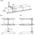
- a portal carries all the job units and the associated peripherals, as well as its own linear drive. There is now the possibility to arrange several of these portals one behind the other to save space. This allows you to quickly build large parts with multiple portals. Furthermore, several components can be created in parallel. ( Fig.10-12 ).
- the Fig. 10 shows a further preferred embodiment of the invention, in which a plurality of portals are provided.
- each portal has the complete set of application facilities and the associated peripherals.
- Each portal acts as an independent machine and creates its own component.
- FIG. 11 is the same construction of the device as in Fig. 10 shown, but here create the two individual portals together a component.
- lifting axles are located on a moving portal, they can be completely removed from the production area ( Fig. 12 ). With a sufficiently long travel, a new construction process can be started directly next to the finished component.
- the process also offers the possibility of a new building strategy: While in conventional processes the coater and the print head are always at the same level, both can move in the Z direction relative to one another.
- one portal can be undercut by the other.
- one job unit of the other must constantly evade, so that empty runs arise in which the respective job unit remains inactive.
- the print head follows the coater and prints the freshly coated construction field. Then the portal lifts the printhead so that it can be driven under the coater portal ( Fig. 16 ) and the coater moves to a new Z position and applies a new coat ( Fig. 17 ). In Fig. 18 The print head then moves back to the current layer height and prints the freshly coated construction field.
- the guide position can be actively swapped.
- the print head follows the coater and imprints the freshly coated construction field.
- the printhead portal raises the printhead so far that it can be driven under the coater portal.
- the coater begins again with the creation of a fresh layer in the opposite direction. During this time, the printhead moves to the current level and can produce the fresh layer. But it is also possible that the coater follows the print head, then the arrangements must be exchanged at the respective portals.
Landscapes
- Engineering & Computer Science (AREA)
- Chemical & Material Sciences (AREA)
- Materials Engineering (AREA)
- Manufacturing & Machinery (AREA)
- Mechanical Engineering (AREA)
- Physics & Mathematics (AREA)
- Optics & Photonics (AREA)
- Coating Apparatus (AREA)
Description
Die Erfindung betrifft eine Vorrichtung und ein Verfahren zum schichtweisen Aufbau von Modellen gemäß dem Oberbegriff des Anspruchs 1 beziehungsweise Anspruchs 10,The invention relates to a device and a method for the layered construction of models according to the preamble of
In der europäischen Patentschrift
Das, wie beschrieben, aus verfestigtem Partikelmaterial hergestellte Objekt ist nach seiner Fertigstellung in losem Partikelmaterial eingebettet und wird anschließend davon befreit.The object made of solidified particulate material as described is embedded in loose particulate matter after its completion and subsequently freed of it.
In ähnlicher Weise arbeiten auch andere Pulver-gestützte Rapid-Prototyping-Prozesse, wie z.B. das selektive Lasersintern oder das Elektron-Beam-Sintern bei denen jeweils ebenso ein loses Partikelmaterial schichtweise ausgebracht und mit Hilfe einer gesteuerten physikalischen Strahlungsquelle selektiv verfestigt wird.Similarly, other powder-based rapid prototyping processes such as e.g. the selective laser sintering or the electron beam sintering in each of which also a loose particulate material is applied in layers and selectively solidified by means of a controlled physical radiation source.
Im Folgenden werden alle diese Verfahren unter dem Begriff "dreidimensionale Druckverfahren" oder 3D-Druckverfahren zusammengefasst.In the following, all these methods are summarized under the term "three-dimensional printing process" or 3D printing process.
Aus der
In der nachveröffentlichten Patentanmeldung
Bei einer solchen Lösung können jedoch Probleme auftreten, da die enthaltene Verfahreinheit in Z-Richtung neben den schichterzeugenden Werkzeugen auch die vertikalen Verfahreinheiten und einen schweren Tragrahmen anheben, so dass der Tragrahmen steif ausgelegt werden muss und nur an wenigen Punkten (vorzugsweise den 4 Gantry-Punkten) sinnvoll aufgehängt werden kann. Eine steife Ausführung des Tragrahmens führt aber zu einer Ausführung von hohem Gewicht, was wiederum hohe Ansprüche an die Z-Achse stellt. Ab einer gewissen Länge kann der dafür notwendige technische Aufwand sich als nicht mehr wirtschaftlich erweisen.In such a solution, however, problems can occur because the included trajectory in the Z direction in addition to the layer-forming Tools also raise the vertical traversing units and a heavy support frame, so that the support frame must be designed stiff and only a few points (preferably the 4 gantry points) can be meaningfully hung. However, a rigid design of the support frame leads to a design of high weight, which in turn makes high demands on the Z-axis. From a certain length of time the necessary technical effort can prove to be no longer economical.
Darüberhinaus hat es sich auch gezeigt, dass mit zunehmendem Verfahrweg in der horizontalen Ebene die Enden des Tragrahmens weit auskragen und damit zum Schwingen neigen. Begünstigt wird dies noch durch verschiedenen Systemkomponenten, wie beispielsweise einem schwingungsangeregten Beschichter, Schwingungsaktoren zur Verbesserung des Materialflusses innerhalb der Materialversorgungskette und Beschleunigungen Verfahreinheiten der ProzesswerkzeugeMoreover, it has also been shown that with increasing travel in the horizontal plane, the ends of the support frame protrude far and thus tend to swing. This is further supported by various system components, such as a vibration-induced coater, vibration actuators to improve the material flow within the material supply chain and accelerations movement units of the process tools
Darüberhinaus sind auch sie Genauigkeitsanforderungen an ein Achssystem mit mehreren Achseinheiten ist sehr hoch. Ein angemessener Lauf muss durch hohe Fertigungsgenaulgkeiten oder eine relativaufwendige Justierung erreicht werden.In addition, they too are accuracy requirements for an axis system with several axis units is very high. An adequate run must be achieved by high manufacturing accuracy or a relatively expensive adjustment.
Aus der
Desweiteren beschreibt die
Die
Ausgehend hiervon ist es Aufgabe der vorliegenden Erfindung eine elnfachere, erwelterbare und leicht verstellbare Vorrichtung bezlehungsweise ein einfaches und vielseitiges Verfahren der eingangs genannten Art bereitzustellen.Proceeding from this, it is the object of the present invention to provide a simple, alternative and easily adjustable device, ie a simple and versatile method of the type mentioned initially.
Die Aufgabe wird durch die in den Ansprüchen 1 und 10 näher bezeichneten Ausführungsformen gelöst.The object is achieved by the embodiments specified in more detail in
Vorteilhafte Ausgestaltungen der Erfindung sind in den Unteransprüchen dargestellt.Advantageous embodiments of the invention are shown in the subclaims.
In einem Aspekt betrifft die Erfindung eine Vorrichtung nach Anspruch 1 zum schichtweisen Aufbau von Modellen, wobei ein Bereich zum Aufbau von Modellen, vorzugsweise eine Bauplattform und eine Materialauftragsvorrichtung zum Auftragen von Material auf den Bereich vorgesehen sind, die Materlalauftragsvorrichtung über dem Bereich verfahrbar angeordnet ist, wobei die Materialauftragsvorrichtung derart als Portal angeordnet ist, dass sie zumindest über zwei sich an gegenüberliegenden Seiten des Bereichs angeordnete Linearführungen über dem Bereich verschiebbar ist, und derart um den Bereich angeordnet ist, dass mit zumindest zwei sich seitlich des Bereichs erstreckenden Abschnitten ein Portal gebildet wird. Dabei ist gemäß der vorliegenden Erfindung zumindest eine weitere Materialauftragsvorrichtung zum Auftragen eines weiteren Materials auf den Bereich vorgesehen.In one aspect, the invention relates to a device according to
Gemäß der vorliegenden Erfindung sind dabei die Linearführungen vorgesehen und die Materialauftragsvorrichtung ist derart um die Fläche angeordnet ist, dass mit zumindest zwei sich seitlich der Fläche erstreckenden Abschnitten ein Portal gebildet wird.According to the present invention, the linear guides are provided and the material application device is arranged around the surface such that a portal is formed with at least two sections extending laterally of the surface.
Unter einer Fläche ist dabei ein Bereich zu verstehen, auf den ein Materialauftrag zum Aufbau von Modellen erfolgt. Dies kann eine gesonderte Bauplattform sein oder auch nur ein Bereich einer Bodenfläche.A surface is to be understood as an area to which a material application for the construction of models takes place. This may be a separate building platform or just an area of a floor surface.
Die Fläche muss dabei auch nicht unbedingt der Baumaterialauftragsebene entsprechen, beziehungsweise zu dieser parallel sein. So könnte es beispielsweise sein, dass für einen kontinuierlichen Aufbauprozess die Baumaterialauftragsebene einen Winkel zur Fläche aufweist.The area does not necessarily have to correspond to the building material application level, or be parallel to it. For example, it could be that, for a continuous building process, the building material application level has an angle to the surface.
Die Materialauftragsvorrichtung ist eine Vorrichtung zum Aufbringen vom Material auf die Fläche. Dies kann beispielsweise eine Materialbeschichter oder ein Flüssigkeitsbeschichter zum Aufbringen von Schichten sein. Ebenso ist beispielsweise auch ein Druckkopf zum selektiven Aufbringen von Material hierfür denkbar.The material applicator is a device for applying the material to the surface. This may be, for example, a material coater or a liquid coater for applying layers. Likewise, for example, a print head for the selective application of material for this purpose is conceivable.
Die Materialauftragsvorrichtung ist dabei für ein Material vorgesehen, das für das jeweilig verwendete 3-D-Verfahren geeignet ist.The material application device is provided for a material which is suitable for the particular 3-D process used.
So wäre es beispielsweise möglich, dass das eine oder mehrere Materialien flüssig und/oder fest, schichtweise in Folien oder als Partikelmaterial und/oder gedruckt und/oder extrudiert aufgetragen wird. Weiterhin können beispielsweise Strahlungsquellen, wie Laser, LED-Belichtungsköpfe, vorgesehen sein, um u.a. einen selektiven Laserprozess oder Sinterprozess oder auch einfach einen Aushärtprozess durchzuführen.For example, it would be possible for the one or more materials to be applied liquid and / or solid, layer by layer in films or as particulate material and / or printed and / or extruded. Further, for example, radiation sources, such as lasers, LED exposure heads, may be provided to provide i.a. Perform a selective laser process or sintering process or simply a curing process.
Die Materialauftragsvorrichtung oder mehrere davon sind daher an den jeweils verwendeten Aufbauprozess angepasst.The material application device or several of them are therefore adapted to the particular building process used.
So ist es beispielsweise auch möglich, dass Material flüssig oder fest schichtweise aufgetragen wird und anschließend über eine zweite Materialauftragsvorrichtung selektiv ein zweites, mit dem ersten aushärtbaren Material aufgetragen wird. Die zweite Materialauftagvorrichtung könnte dabei gemeinsam mit der ersten Materialauftragsvorrichtung mit einer Linearführung in Eingriff stehen oder auch von der ersten getrennt mit einer Linearführung in Eingriff stehen.Thus, for example, it is also possible for the material to be applied liquid or solid in layers, and then a second, selectively applied material to be applied via the second material application device. The second Materialauftagvorrichtung could stand together with the first material application device with a linear guide in engagement or stand separately from the first with a linear guide in engagement.
Weiter wäre auch ein Einsatz bei einem Druckverfahren mit direktem Materialauftrag durch einen Druckkopf, zum Beispiel Poly-Jet Modeling, Multi-Jet Modeling oder bei Extrusionsverfahren mit direktem Materialauftrag durch eine Düse zum Beispiel dem Fused-Deposition-Modeling denkbar. Wenn dies der Fall ist, dann könnte die Materialauftragsvorrichtung eine Partikelmaterialbeschichtervorrichtung und/oder einen Druckkopf und/oder einen Extruder und/oder einen Folienbeschichter umfassen.It would also be conceivable to use a printing method with direct material application by a print head, for example poly-jet modeling, multi-jet modeling or extrusion processes with direct application of material through a nozzle, for example fused deposition modeling. If this is the case, then the material application apparatus could comprise a particle material coating apparatus and / or a printhead and / or an extruder and / or a film coater.
Die Linearführungen sind dabei Vorrichtungsteile die zum Führen der Portalteile in linearer Richtung geeignet sind. So wäre es beispielsweise denkbar, dass die eine Bauplattform auf einer Bodenebene angeordnet ist und an zwei sich gegenüberliegenden Seiten zwei Profile angeordnet sind, an die die Portalteile angelenkt sind und an damit linear verschiebbar sind.The linear guides are device parts which are suitable for guiding the portal parts in the linear direction. Thus, it would be conceivable, for example, that the one building platform is arranged on a floor level and two profiles are arranged on two opposite sides, to which the portal parts are articulated and are thus linearly displaceable.
Als ein Vorteil der vorliegenden Erfindung hat es sich erwiesen, dass für den Fall, dass die Verfahrlänge einer Anlage erweitert werden soll, nicht der gesamte Tragrahmen verlängert und neu ausgelegt werden muss, sondern einfach die Linearführung entsprechend länger ausgewählt werden muss. Alle anderen Komponenten bleiben identisch.As an advantage of the present invention, it has been found that in the event that the travel length of a system is to be extended, not the entire support frame must be extended and redesigned, but simply the linear guide must be selected correspondingly longer. All other components remain identical.
Darüberhinaus ist die Materialauftragsvorrichtung als Portal angeordnet, das über stabile Linearführungen gesteuert wird, die beispielsweise am Boden befestigt sein können. Somit ist der Aufbau einer erfindungsgemäßen Vorrichtung sehr stabil und erfordert nur eine sehr geringe zusätzlich Aufstellfläche.Moreover, the material application device is arranged as a portal, which is controlled by stable linear guides, which may be attached to the ground, for example. Thus, the structure a device according to the invention is very stable and requires only a very small additional footprint.
Da nun also lediglich Portale und keine aufwändigen Rahmengestelle vorgesehen sind ist nach Abschluss eines Bauprozesses die erstellte Form gut zugänglich.Since now only portals and no elaborate frames are provided after completion of a construction process, the created form is easily accessible.
Gemäß einer Ausführungsform ist dabei die weitere Materialauftragsvorrichtung ebenso an dem Portal vorgesehen, so dass auch hier die oben beschriebenen Vorteile zutreffen.According to one embodiment, the further material application device is also provided on the portal, so that here too the advantages described above apply.
Um den Auftrag beider Materialauftragsvorrichtungen etwas unabhängiger und eventuell auch sogar zeitversetzt aber teilweise auch gleichzeitig voneinander gestalten zu können ist es auch vorgesehen, dass die weitere Materialauftragsvorrichtung an einem weiteren Portal vorgesehen ist.In order to be able to make the order of both material application devices somewhat more independent and possibly even with a time delay, but sometimes also simultaneously from one another, provision is also made for the further material application device to be provided on another portal.
Gemäß einer bevorzugten Ausführungsform der vorliegenden Erfindung umfasst die Materialauftragsvorrichtung eine Partikelmaterialbeschichtervorrichtung und/oder einen Druckkopf.According to a preferred embodiment of the present invention, the material application device comprises a particle material coating device and / or a printhead.
Dabei können an einem Portal beispielsweise eine Partikelmaterialschichtauftragsvorrichtung sowie ein Druckkopf zum selektiven Auftragen für das jeweilige Partikelmaterial geeignete Bindermaterial vorgesehen sein.In this case, for example, a particle material layer application device and a print head for selective application of binder material suitable for the respective particle material may be provided on a portal.
Darüberhinaus ist es auch möglich, dass ein Portal eine Licht-, eine Strahlungs- und/oder eine Wärmequelle aufweist.Moreover, it is also possible that a portal has a light, a radiation and / or a heat source.
Als vorteilhaft hat es sich zudem erwiesen, wenn bei einer erfindungsmäßen Vorrichtung die Materialauftragsvorrichtung im wesentlichen senkrecht zu dem Bereich verfahrbar angeordnet ist. Dies bedeutet, dass die Materialauftragsvorrichtung auch in der Höhe verfahren werden kann, sodass eine solche Vorrichtung auch für Systeme einsetzbar ist, bei denen die Bauplattform, auf der ein Objekt aufgebaut wird, nicht höhenverfahrbar ist Es hat sich gezeigt, dass bei einer solchen Ausführungsform ein Verfahren der Materialauftragsvorrichtung, der weitere Materialauftragsvorrichtung, der Licht-, Strahlungs- und/oder Wärmequelle im Wesentlichen senkrecht zur Auftragsebene vorzugsweise entlang der Portalteile erfolgen kann.It has also proved to be advantageous if, in a device according to the invention, the material application device is arranged to be movable substantially perpendicularly to the region. This means that the material application device can also be moved in height, so that such a device can also be used for systems in which the construction platform on which an object is built, is not vertically movable. It has been shown that in such an embodiment Method of the material application device, the further material application device, the light, radiation and / or heat source can be carried out substantially perpendicular to the application plane preferably along the portal parts.
Das weitere Portalteil könnte dabei ebenso wie das erste Portal mit der Linearführung oder aber mit einer weiteren Linearführung in Eingriff stehen. Es sollen die Portalteile aber jedenfalls unabhängig voneinander auf der oder den Linearführungen verfahrbar sein.The other portal part could be just like the first portal with the linear guide or with another linear guide engaged. However, the portal parts should at least be moved independently of one another on the or the linear guides.
Wenn nun zwei Portale vorgesehen sind, kann es insbesondere vorteilhaft sein, wenn die beiden Materialauftragsvorrichtungen unterfahrbar beziehungsweise überfahrbar sind. Dies bedeutet, dass ein Portal unter dem anderen hindurchfahren kann.Now, if two portals are provided, it may be particularly advantageous if the two material application devices are accessible or can be driven over. This means that one portal can pass under the other.
Ist die erfindungsgemäße Vorrichtung derart vorgesehen, kann in beiden Fahrtrichtungen beschichtet werden. Dadurch werden Leerfahrten vermieden. Dies bringt insbesondere dann auch einen Vorteil, wenn bei den verwendeten Druckköpfen die Druckbreite der Baufeldbreite entspricht.If the device according to the invention is provided in this way, it can be coated in both directions of travel. This avoids empty runs. This also brings an advantage, in particular, if the print width used in the print heads used corresponds to the construction field width.
Gemäß einer weiteren bevorzugten Ausführungsform der erfindungsgemäßen Vorrichtung ist mindestens ein Peripheriegerät der Materialauftragseinrichtung fest in der Vorrichtung positioniert und unabhängig von der aktuellen Bauhöhe von der Auftragseinrichtung anfahrbar.According to a further preferred embodiment of the device according to the invention, at least one peripheral device of the material application device is firmly positioned in the device and can be approached by the application device independently of the current height.
Unter Peripheriegeräten sind dabei beispielsweise die Reinigungseinheit des Druckkopfes oder die Materialversorgung des Beschichters zu verstehen. Sind diese nicht am Portal, sondern irgendwo sonst in der Vorrichtung fest positioniert, müssen diese nicht mit dem Portal angehoben werden.Under peripheral devices are to be understood, for example, the cleaning unit of the print head or the material supply of the coater. If these are not firmly positioned on the portal but somewhere else in the device, they do not have to be lifted with the portal.
Gemäß einem weiteren Aspekt der vorliegenden Erfindung wird auch ein Vertahren nach Anspruch 10 zum schichtweisen Aufbau von Modellen bereitgestellt, wobei eine Fläche zum Aufbau von Modellen, vorzugsweise eine Bauplattform und zumindest eine Materialauftragsvorrichtung zum Auftragen von Material auf die Fläche vorgesehen sind.According to another aspect of the present invention, there is also provided a method of layering models according to claim 10, wherein a model building surface, preferably a building platform, and at least one material applicator are provided for applying material to the surface.
Die Materialauftragsvorrichtung verfährt über der Fläche entlang zumindest zwei sich an gegenüberliegenden Seiten der Fläche angeordnete Linearführungen in Richtung der Auftragsebene.The material application device moves over the surface along at least two linear guides arranged on opposite sides of the surface in the direction of the application plane.
Das Portal ist dabei derart angeordnet, dass die Materialauftragsvorrichtung zumindest entlang zwei sich an gegenüberliegenden Seiten des Bereichs angeordnete Linearführungen über dem Bereich verfährt, und derart um den Bereich angeordnet ist, dass mit zumindest zwei seitlich des Bereichs erstreckenden Abschnitten ein Portal gebildet wird. Gemäß der vorliegenden Erfindung ist zumindest eine weitere Materialauftragsvorrichtung an einem weiteren Portal vorgesehen und ein weiteres Material wird auf den Bereich aufgebracht.The portal is arranged such that the material application device moves over at least two linear guides arranged on opposite sides of the area, and is arranged around the area such that a portal is formed with at least two sections extending laterally of the area. According to the present invention, at least one further material application device is provided on another portal and another material is applied to the region.
Die Linearführungen sind dabei vorzugsweise unterhalb der Materialauftragsvorrichtung angeordnet und zumindest über jeweils ein nach oben im Wesentlichen in Richtung senkrecht zur Bauplattform erstreckendes Portalteil in Eingriff und die beiden Portalteile zumindest über die Materialauftragsvorrichtung miteinander verbunden und die Materialauftragsvorrichtung verfährt entlang der Linearführungen über der Fläche.The linear guides are preferably arranged underneath the material application device and engage at least via one portal part extending upwards essentially in the direction perpendicular to the build platform and the two portal parts are connected to one another at least via the material application device and the material application device moves along the linear guides over the surface.
Gemäß der vorliegenden Erfindung verfährt die Materialauftragsvorrichtung auch senkrecht zur Fläche, was insbesondere bei der Verwendung von nicht höhenverfahrbaren Bauplattformen Vorteile bietet.According to the present invention, the material application device also moves perpendicular to the surface, which offers advantages in particular when using non-height-adjustable construction platforms.
Werden bei einer bevorzugten Ausgestaltung des erfindungsgemäßen Verfahrens mehrere eigenständige Portale verwendet, so können diese gleichzeitig unterschiedliche Bauprozesse durchführen. Das bedeutet, dass auf einer Fläche in verschiedenen Bereichen verschiedene, voneinander unabhängige Bauprozesse stattfinden können.If a plurality of independent portals are used in a preferred embodiment of the method according to the invention, they can simultaneously carry out different construction processes. This means that different, independent building processes can take place on one area in different areas.
Daneben wäre es aber ebenso denkbar, dass von mehreren eigenständigen Portalen gleichzeitig ein gemeinsamer Bauprozess durchgeführt werden kann.In addition, it would also be conceivable that a common construction process can be carried out simultaneously by several independent portals.
Die zumindest zwei Portale können sich auch gemäß einer noch weiteren bevorzugten Ausführungsform während oder nach einem Prozessschritt gegenseitig unterfahrbaren beziehungsweise überfahrbaren.The at least two portals may also, in accordance with yet another preferred embodiment, be mutually traversable or passable during or after a process step.
Zur näheren Erläuterung wird die Erfindung anhand bevorzugter Ausführungsbeispiele in den folgenden Zeichnungen dargestellt.For further explanation, the invention is illustrated by means of preferred embodiments in the following drawings.
In der Zeichnung zeigt dabei:
-
Figur 1bis 4 -
Figur 5 und 6 -
Fig. 7 ein höhenverstellbares Peripheriegerät gemäß einer weiteren bevorzugten Ausführungsform, sich an die Baufeldgröße anpasst; -
Fig. 8-9 ein stationäres Peripheriegerät; -
Fig. 10 eine Ausführungsform mit Einzelportalen; -
Fig. 11 eine Ausführungsform gemäßFig. 10 , wobei zwei Einzelportale gemeinsam ein Bauteil erstellen; -
Fig. 12 eine Ausführungsform, bei der drei Einzelportale eigenständig Bauteile erstellen; -
Fig. 13 eine Ausführungsform, bei der ein Einzelportal mehrere Bauteile fertigt; und -
Fig. 14 -18 den Ablauf eines erfindungsgemäßen Verfahrens gemäß einer besonders bevorzugten Ausführungsform.
-
Figure 1 to 4 a process flow according to a preferred embodiment of the present invention, wherein a Pulvermaterialbeschichter and a Durckkopf have their own portal; -
FIGS. 5 and 6 a height-adjustable peripheral device according to another preferred embodiment, which adapts to the height; -
Fig. 7 a height-adjustable peripheral device according to a further preferred embodiment, adapts to the construction field size; -
Fig. 8-9 a stationary peripheral device; -
Fig. 10 an embodiment with single portals; -
Fig. 11 an embodiment according toFig. 10 where two single portals together create a component; -
Fig. 12 an embodiment in which three individual portals independently create components; -
Fig. 13 an embodiment in which a single portal manufactures several components; and -
Fig. 14 -18 the sequence of a method according to the invention according to a particularly preferred embodiment.
Gemäß der vorliegenden Erfindung wird eine Vorrichtung bzw. ein Verfahren zum Herstellen dreidimensionaler Modelle mittels 3-D Druckverfahren auf eine Fläche beschrieben, wobei Materialauftragsvorrichtungen (beispielsweise Partikel material beschichtereinheit bzw. Druckkopfeinheit) vorgesehen sind, um auf eine Fläche das jeweilige Material aufzutragen. Die Materialauftragsvorrichtungen werden dabei gemäß der vorliegenden Erfindung an einem oder mehreren Portalen vertikal bewegt.According to the present invention, a device or a method for producing three-dimensional models by means of 3-D printing method described on a surface, wherein material application devices (for example, particle material coating unit or printhead unit) are provided to apply to a surface of the respective material. The material application devices are thereby moved vertically in accordance with the present invention on one or more portals.
Die mit bezug auf die
Werden mehrere Portale 1, 1` eingesetzt, ist es möglich die Portale 1, 1` jeweils mit einem eigenen Antrieb zu versehen und nur eine gemeinsame Führungsbahn 2 zu nutzen. Es ist aber auch möglich jedem Portaleine eigene Lineareinheit 2 (Antrieb mit Führung) zuzuordnen.If
Bei einem Verfahren zum Aufbau von Modellen mittels Partikelmaterial und selektivem bedrucken des Partikelmaterials werden folgende Fahrtrichtungen unterschieden:
- Fahrtrichtung zur Positionierung des Druckkopfes
- Fahrtrichtung der Druckfahrt des Druckkopfes
- Beschichtungsrichtung des Beschichters
- Direction of travel for positioning the printhead
- Direction of travel of the print run of the print head
- Coating direction of the coater
In welcher Richtung die längste Fahrt angeordnet wird, ist abhängig vom Verfahren bzw. der Drucktaktik. Es wird als sinnvoll erachtet die längste Achse (z.B. die Achse in Beschichtungsrichtung) fest mit dem Boden zu verbinden.The direction in which the longest journey is arranged depends on the method or the pressure tactic. It is considered useful to firmly connect the longest axis (e.g., the axis in the coating direction) to the ground.
Die feste Anbindung der Führungseinheiten am Boden schließt Durchbiegung und Schwingungen unabhängig von der Verfahrlänge aus.The fixed connection of the guide units on the floor eliminates deflection and vibration regardless of the travel length.
Durch den Verzicht auf einen vertikal bewegten Tragrahmen, wie es aus dem Stand der Technik bekannt ist, werden bei einer erfindungsgemäßen Ausführung deutlich Kosten und Aufwand bei der Auslegung, Konstruktion, Herstellung, Transport und Montage der Vorrichtung eingespart.By dispensing with a vertically moving support frame, as is known from the prior art, significant cost and effort in the design, construction, manufacture, transport and installation of the device are saved in an embodiment of the invention.
Soll eine Anlage vergrößert werden, ist dies mit vergleichsweise geringem Aufwand möglich. Die Montage reduziert sich lediglich auf den Tausch oder die Erweiterung der Lineareinheiten. Bei geschickter Gestaltung muss lediglich die Führung verlängert werden.If a system is to be increased, this is possible with relatively little effort. The assembly is only reduced to the exchange or extension of the linear units. With skillful design, only the guide needs to be extended.
Die Auftragseinheiten und die Peripherie (Druckkopfreinigung, Druckkopfparkstation, Beschichterbefüllstation) können optional mit bewegt werden, oder auch fest neben der Bauplattform positioniert werden.The application units and the peripherals (printhead cleaning, printhead parking station, coater filling station) can optionally be moved, or also be positioned firmly next to the build platform.
Das kastenlose Bauen der Objekte ermöglicht, dass die Baufeldgröße beliebig variiert werden kann.The boxless building of the objects allows that the construction field size can be varied as desired.
Um die Bauzeit möglichst gering zu halten kann es sinnvoll sein, die zughörigen Peripheriegeräte mit den entsprechenden Portalen mitfahren zu lassen (Pos.8 in
Daneben können die Peripheriegeräte 6 aber auch stationär am Baufeldrand angeordnet sein. Dort können Sie beispielsweise in vertikaler Richtung mit einer eigenen Hubeinrichtung entsprechend der aktuellen Bau-bzw. Werkzeughöhe positioniert werden (
Das Peripheriegerät 6 weist hier also eine eigene Hubeinrichtung auf und kann sich damit der aktuellen Bauhöhe und damit der vertikalen Position der Materialauftragseinrichtung bzw. der Härtungseinrichtung anpassen. Der Unterschied zwischen
Da eine Auftragseinrichtung an einem Portal in mindestens zwei Richtungen positioniert werden kann, besteht die Möglichkeit die dazugehörigen Peripheriegeräte 7 zu fixieren und damit nicht zu bewegen. Dann wird das Peripheriegerät 7 direkt von der Auftragseinheit 4, 5 angefahren (
Fahren die Peripheriegeräte 6 nicht am Portal mit, kann deren Position an die Baufeldgröße vor Baubeginn angepasst werden (
Dies stellt vor allem dann eine bevorzugte, kostengünstige Lösung dar, wenn eine vertikale Positionierung der Peripherie und Prozessmedien aufwendig ist.This is especially a preferred, cost-effective solution, if a vertical positioning of the periphery and process media is expensive.
In einer bestimmten Ausführung trägt ein Portal alle Auftragseinheiten und die dazugehörige Peripherie sowie einen eigenen Linearantrieb. Es besteht hier nun die Möglichkeit mehrere dieser Portale hintereinander platzsparend anzuordnen. So können mit mehreren Portalen schnell große Teile aufgebaut werden. Weiter können auch mehrere Bauteile parallel erstellt werden. (
Die
In der
Dies kann nun auch beliebig erweitert werden, so zeigt beispielsweise
Befinden sich Hubachsen an einem verfahrenden Portal, können diese ganz aus dem Fertigungsbereich entfernt werden (
Daneben ist es auch denkbar, dass ein Einzelportal mehrere Bauteile parallel oder einzeln fertigt, wie dies in
Das Verfahren bietet erstmals auch die Möglichkeit einer neuen Bautaktik: Während bei konventionellen Prozessen Beschichter und Druckkopf immer auf gleichem Niveau sind, können hier beide in Z-Richtung relativ zueinander verfahren.For the first time, the process also offers the possibility of a new building strategy: While in conventional processes the coater and the print head are always at the same level, both can move in the Z direction relative to one another.
Bei geschickter Ausführung und Anordnung der Portale, kann ein Portal vom anderem unterfahren werden. Bei herkömmlichen Prozessen muss eine Auftragseinheit der Anderen ständig ausweichen, so dass Leerfahrten entstehen, in denen die jeweilige Auftragseinheit inaktiv bleibt.With skillful execution and arrangement of the portals, one portal can be undercut by the other. In conventional processes, one job unit of the other must constantly evade, so that empty runs arise in which the respective job unit remains inactive.
In
Bei dieser gezeigten bevorzugten Ausführungsform kann die die Führungsposition aktiv getauscht werden. In der dargestellten Abfolge von
Das bedeutet, dass der Beschichter erstmals in jeder Fahrtrichtung, das heißt bei jeder Fahrt beschichten kann. Ebenso können erstmals Druckköpfe deren Druckbreite der Baufeldbreite entsprechen, in jeder Fahrtrichtung und bei jeder Fahrt beschichten. Damit wird die Effizienz des gesamten Systems erheblich gesteigert.This means that the coater can coat for the first time in every direction of travel, that is to say every ride. Similarly, for the first time printheads whose print width correspond to the construction field width, coat in every direction and on every ride. This significantly increases the efficiency of the entire system.
Claims (13)
- A device for the layered construction of models, wherein there are provided a region for the construction of models, preferably a construction platform, and a material application device (4) for applying material onto said region, said material application device (4) being arranged so as to be movable over said region, and said material application device (4) being arranged as a portal (1) such that it can be moved over said region via at least two linear guides (2) arranged on opposite sides of said region, and said material application device (4) further being arranged around said region such that a portal (1) is formed with at least two portions extending laterally of said region, characterised in that
at least one further material application device (5) for applying a further material onto said region is provided, said further material application device (5) being provided at a further portal (1'), the material application devices (4, 5) being movable substantially perpendicular to said region and the portals being independently movable on the linear guides (2). - The device according to any one of the preceding claims,
characterised in that
a light, radiation and/or heat source is provided on one of the portals (1, 1') or on still further portals. - The device according to any one of the preceding claims,
characterised in that
the further portal or all portals is/are in engagement with the linear guide. - The device according to any one of claims 1 and 2,
characterised in that
the further portal is in engagement with a further linear guide. - The device according to any one of the preceding claims,
characterised in that
the material application device (4) comprises a particulate material coating device and said further material application device (5) comprises a print head and/or an extruder and/or a film coater. - The device according to any one of the preceding claims,
characterised in that
the at least one light, radiation and/or heat source is arranged so as to be movable substantially perpendicular to said region. - The device according to claim 6,
characterised in that
the material application devices (4, 5) and the light, radiation and/or heat source can be moved along lateral portal parts. - The device according to any one of the preceding claims, characterised in that the portals (1, 1') can be moved under one another or over one another, respectively.
- The device according to any one of the preceding claims, characterised in that at least one peripheral device is additionally arranged in the device, said peripheral device being accessible regardless of the height of the portals (1, 1').
- A method for the layered construction of models, wherein there are provided a region for the construction of models, preferably a construction platform, and at least one material application device (4) for applying material onto said region, said material application device (4) moving over said region, and said material application device (4) being arranged as a portal (1) so as to move over said region along at least two linear guides (2) arranged on opposite sides of said region, and said material application device (4) further being arranged around said region such that a portal (1) is formed with at least two portions extending laterally of said region, characterised in that at least one further material application device (5) is provided at a further portal (1') and a further material is applied to said region, the material application devices (4, 5) being movable substantially perpendicular to said region and the portals being movable independently of each other on the linear guides (2).
- The method according to claim 10,
characterised in that
at least two portals (1, 1') can move under or over one another, respectively, during or after a process step. - The method according to any one of claims 10 to 11,
characterised in that a plurality of independent portals (1, 1') simultaneously perform different construction processes. - The method according to any one of claims 10 to 12,
characterised in that
a plurality of independent portals (1, 1') simultaneously perform a common construction process.
Applications Claiming Priority (2)
| Application Number | Priority Date | Filing Date | Title |
|---|---|---|---|
| DE102011111498A DE102011111498A1 (en) | 2011-08-31 | 2011-08-31 | Device for the layered construction of models |
| PCT/DE2012/000870 WO2013029594A1 (en) | 2011-08-31 | 2012-08-29 | Device for constructing models in layers |
Publications (2)
| Publication Number | Publication Date |
|---|---|
| EP2750865A1 EP2750865A1 (en) | 2014-07-09 |
| EP2750865B1 true EP2750865B1 (en) | 2016-12-14 |
Family
ID=47048912
Family Applications (1)
| Application Number | Title | Priority Date | Filing Date |
|---|---|---|---|
| EP12775432.3A Active EP2750865B1 (en) | 2011-08-31 | 2012-08-29 | Device and method for constructing models in layers |
Country Status (6)
| Country | Link |
|---|---|
| US (2) | US9878494B2 (en) |
| EP (1) | EP2750865B1 (en) |
| KR (2) | KR20140061432A (en) |
| CN (1) | CN103764376B (en) |
| DE (1) | DE102011111498A1 (en) |
| WO (1) | WO2013029594A1 (en) |
Families Citing this family (70)
| Publication number | Priority date | Publication date | Assignee | Title |
|---|---|---|---|---|
| WO2002026419A1 (en) | 2000-09-25 | 2002-04-04 | Generis Gmbh | Method for producing a part using a deposition technique |
| DE102006038858A1 (en) | 2006-08-20 | 2008-02-21 | Voxeljet Technology Gmbh | Self-hardening material and method for layering models |
| US10226919B2 (en) | 2007-07-18 | 2019-03-12 | Voxeljet Ag | Articles and structures prepared by three-dimensional printing method |
| DE102007050679A1 (en) | 2007-10-21 | 2009-04-23 | Voxeljet Technology Gmbh | Method and device for conveying particulate material in the layered construction of models |
| DE102007050953A1 (en) | 2007-10-23 | 2009-04-30 | Voxeljet Technology Gmbh | Device for the layered construction of models |
| DE102010006939A1 (en) | 2010-02-04 | 2011-08-04 | Voxeljet Technology GmbH, 86167 | Device for producing three-dimensional models |
| DE102010014969A1 (en) | 2010-04-14 | 2011-10-20 | Voxeljet Technology Gmbh | Device for producing three-dimensional models |
| DE102010015451A1 (en) | 2010-04-17 | 2011-10-20 | Voxeljet Technology Gmbh | Method and device for producing three-dimensional objects |
| DE102010056346A1 (en) | 2010-12-29 | 2012-07-05 | Technische Universität München | Method for the layered construction of models |
| DE102011007957A1 (en) | 2011-01-05 | 2012-07-05 | Voxeljet Technology Gmbh | Device and method for constructing a layer body with at least one body limiting the construction field and adjustable in terms of its position |
| DE102011105688A1 (en) | 2011-06-22 | 2012-12-27 | Hüttenes-Albertus Chemische Werke GmbH | Method for the layered construction of models |
| DE102011111498A1 (en) | 2011-08-31 | 2013-02-28 | Voxeljet Technology Gmbh | Device for the layered construction of models |
| DE102012004213A1 (en) * | 2012-03-06 | 2013-09-12 | Voxeljet Technology Gmbh | Method and device for producing three-dimensional models |
| DE102012010272A1 (en) | 2012-05-25 | 2013-11-28 | Voxeljet Technology Gmbh | Method for producing three-dimensional models with special construction platforms and drive systems |
| DE102012012363A1 (en) | 2012-06-22 | 2013-12-24 | Voxeljet Technology Gmbh | Apparatus for building up a layer body with a storage or filling container movable along the discharge container |
| DE102012020000A1 (en) | 2012-10-12 | 2014-04-17 | Voxeljet Ag | 3D multi-stage process |
| DE102013004940A1 (en) | 2012-10-15 | 2014-04-17 | Voxeljet Ag | Method and device for producing three-dimensional models with tempered printhead |
| DE102012022859A1 (en) | 2012-11-25 | 2014-05-28 | Voxeljet Ag | Construction of a 3D printing device for the production of components |
| DE102013003303A1 (en) | 2013-02-28 | 2014-08-28 | FluidSolids AG | Process for producing a molded part with a water-soluble casting mold and material system for its production |
| DE102013018182A1 (en) | 2013-10-30 | 2015-04-30 | Voxeljet Ag | Method and device for producing three-dimensional models with binder system |
| DE102013018031A1 (en) | 2013-12-02 | 2015-06-03 | Voxeljet Ag | Swap body with movable side wall |
| DE102013020491A1 (en) | 2013-12-11 | 2015-06-11 | Voxeljet Ag | 3D infiltration process |
| DE102013021091A1 (en) | 2013-12-18 | 2015-06-18 | Voxeljet Ag | 3D printing process with rapid drying step |
| EP2886307A1 (en) | 2013-12-20 | 2015-06-24 | Voxeljet AG | Device, special paper and method for the production of moulded components |
| DE102013021891A1 (en) * | 2013-12-23 | 2015-06-25 | Voxeljet Ag | Apparatus and method with accelerated process control for 3D printing processes |
| DE102014004692A1 (en) | 2014-03-31 | 2015-10-15 | Voxeljet Ag | Method and apparatus for 3D printing with conditioned process control |
| CN103921333A (en) * | 2014-04-21 | 2014-07-16 | 苏州美迈快速制造技术有限公司 | Three-dimensional ink-jet printer for sand molds |
| DE102014007584A1 (en) | 2014-05-26 | 2015-11-26 | Voxeljet Ag | 3D reverse printing method and apparatus |
| KR102288589B1 (en) | 2014-08-02 | 2021-08-12 | 복셀젯 아게 | Method and casting mould, in particular for use in cold casting methods |
| DE102014224176A1 (en) * | 2014-11-26 | 2016-06-02 | Weeke Bohrsysteme Gmbh | Device for the formation of solids |
| DE102015006533A1 (en) | 2014-12-22 | 2016-06-23 | Voxeljet Ag | Method and device for producing 3D molded parts with layer construction technique |
| US10953600B2 (en) * | 2015-01-30 | 2021-03-23 | Hewlett-Packard Development Company, L.P. | Generating 3D objects |
| DE102015003372A1 (en) | 2015-03-17 | 2016-09-22 | Voxeljet Ag | Method and device for producing 3D molded parts with double recoater |
| DE102015006363A1 (en) | 2015-05-20 | 2016-12-15 | Voxeljet Ag | Phenolic resin method |
| EP3310561A4 (en) * | 2015-06-19 | 2019-02-20 | Applied Materials, Inc. | DISTRIBUTION AND COMPACTION OF MATERIAL IN ADDITIVE MANUFACTURE |
| DE102015110264A1 (en) | 2015-06-25 | 2016-12-29 | Cl Schutzrechtsverwaltungs Gmbh | Device for the generative production of at least one three-dimensional object |
| DE102015011503A1 (en) | 2015-09-09 | 2017-03-09 | Voxeljet Ag | Method for applying fluids |
| KR20180042305A (en) | 2015-09-16 | 2018-04-25 | 어플라이드 머티어리얼스, 인코포레이티드 | Adjustable Z-axis Printhead Module for Multilayer Manufacturing Systems |
| DE102015011790A1 (en) | 2015-09-16 | 2017-03-16 | Voxeljet Ag | Device and method for producing three-dimensional molded parts |
| KR20240155375A (en) * | 2015-10-30 | 2024-10-28 | 쇠라 테크널러지스 인코포레이티드 | Additive manufacturing system and method |
| DE102015015353A1 (en) | 2015-12-01 | 2017-06-01 | Voxeljet Ag | Method and device for producing three-dimensional components by means of an excess quantity sensor |
| DE102015016464B4 (en) | 2015-12-21 | 2024-04-25 | Voxeljet Ag | Method and device for producing 3D molded parts |
| CN107031038A (en) | 2016-01-29 | 2017-08-11 | 三纬国际立体列印科技股份有限公司 | Three-dimensional printing device |
| DE102016002777A1 (en) * | 2016-03-09 | 2017-09-14 | Voxeljet Ag | Method and device for producing 3D molded parts with construction field tools |
| DE102016209933A1 (en) * | 2016-06-06 | 2017-12-07 | Eos Gmbh Electro Optical Systems | Apparatus and method for generatively producing a three-dimensional object |
| JP6876915B2 (en) * | 2016-07-07 | 2021-05-26 | 富士フイルムビジネスイノベーション株式会社 | Modeling equipment |
| AT518899B1 (en) * | 2016-08-05 | 2018-02-15 | Metallconcept Gmbh | Apparatus for producing at least one three-dimensional composite body for the construction industry |
| KR101778999B1 (en) * | 2016-10-05 | 2017-09-18 | 주식회사 퓨쳐캐스트 | A Device and Method for Manufacturing Architectural 3 Dimensional Shape |
| DE102016013610A1 (en) | 2016-11-15 | 2018-05-17 | Voxeljet Ag | Intra-head printhead maintenance station for powder bed-based 3D printing |
| CN108215177B (en) * | 2017-04-27 | 2024-04-19 | 共享智能装备(安徽)有限公司 | 3D printing equipment capable of improving printing efficiency and 3D printing method thereof |
| EP3418033B1 (en) * | 2017-06-19 | 2020-01-01 | Cubicure GmbH | Method and device for lithography-based generative production of three-dimensional forms |
| DE102017006860A1 (en) | 2017-07-21 | 2019-01-24 | Voxeljet Ag | Method and device for producing 3D molded parts with spectrum converter |
| DE102017116537A1 (en) * | 2017-07-21 | 2019-01-24 | Exone Gmbh | 3D printer with coater and coater cleaning device and method for cleaning a coater with a cleaning device |
| EP3473410A1 (en) * | 2017-10-20 | 2019-04-24 | CL Schutzrechtsverwaltungs GmbH | Build material application device |
| JP6961461B2 (en) * | 2017-10-27 | 2021-11-05 | 三菱重工業株式会社 | Laminated modeling equipment |
| DE102018006473A1 (en) | 2018-08-16 | 2020-02-20 | Voxeljet Ag | Method and device for the production of 3D molded parts by means of layer construction technology by means of a closure device |
| DE102019000796A1 (en) | 2019-02-05 | 2020-08-06 | Voxeljet Ag | Exchangeable process unit |
| EP3718748A1 (en) * | 2019-04-02 | 2020-10-07 | Concept Laser GmbH | Apparatus for additively manufacturing three-dimensional objects |
| EP3718746A1 (en) | 2019-04-02 | 2020-10-07 | Concept Laser GmbH | Apparatus for additively manufacturing three-dimensional objects |
| DE102019004176A1 (en) | 2019-06-14 | 2020-12-17 | Voxeljet Ag | Method and device for the production of 3D molded parts by means of layering technology and coater with vacuum seal |
| DE102019007073A1 (en) | 2019-10-11 | 2021-04-15 | Voxeljet Ag | Method and device for the production of 3D molded parts by means of high-performance radiators |
| DE102019007595A1 (en) | 2019-11-01 | 2021-05-06 | Voxeljet Ag | 3D PRINTING PROCESS AND MOLDED PART MANUFACTURED WITH LIGNINE SULPHATE |
| US11504879B2 (en) | 2020-04-17 | 2022-11-22 | Beehive Industries, LLC | Powder spreading apparatus and system |
| CN112092366A (en) * | 2020-08-21 | 2020-12-18 | 孟自力 | 3D printing device and equipment for preparing cardiovascular stent |
| US11633799B2 (en) * | 2020-10-01 | 2023-04-25 | Hamilton Sundstrand Corporation | Control assembly fabrication via brazing |
| US12162074B2 (en) | 2020-11-25 | 2024-12-10 | Lawrence Livermore National Security, Llc | System and method for large-area pulsed laser melting of metallic powder in a laser powder bed fusion application |
| NL1044139B1 (en) * | 2021-09-02 | 2023-03-20 | Adrianus Franciscus Van Der Geest Ing | 13 style 3d printer with multiple XZ portals. |
| WO2023062411A1 (en) * | 2021-10-14 | 2023-04-20 | Project42 S.R.L. | Digital printer for the decoration of slab-shaped manufactured articles |
| EP4647243A1 (en) * | 2023-01-05 | 2025-11-12 | Nanjing University of Aeronautics and Astronautics | Heated-bed deformation tolerance structure for large-sized continuous fiber high-temperature 3d printer |
| USD1106489S1 (en) * | 2023-09-29 | 2025-12-16 | Axogen Corporation | Material layering device |
Family Cites Families (293)
| Publication number | Priority date | Publication date | Assignee | Title |
|---|---|---|---|---|
| US4247508B1 (en) | 1979-12-03 | 1996-10-01 | Dtm Corp | Molding process |
| DE3221357A1 (en) | 1982-06-05 | 1983-12-08 | Plasticonsult GmbH Beratungsgesellschaft für Kunststoff- und Oberflächentechnik, 6360 Friedberg | Process for the production of moulds and cores for casting purposes |
| US4665492A (en) | 1984-07-02 | 1987-05-12 | Masters William E | Computer automated manufacturing process and system |
| US4575330A (en) | 1984-08-08 | 1986-03-11 | Uvp, Inc. | Apparatus for production of three-dimensional objects by stereolithography |
| JPS62275734A (en) | 1986-05-26 | 1987-11-30 | Tokieda Naomitsu | Method for forming solid |
| IL84936A (en) | 1987-12-23 | 1997-02-18 | Cubital Ltd | Three-dimensional modelling apparatus |
| US4752352A (en) | 1986-06-06 | 1988-06-21 | Michael Feygin | Apparatus and method for forming an integral object from laminations |
| DE3750931T3 (en) | 1986-10-17 | 1999-12-02 | Board Of Regents, The University Of Texas System | METHOD AND DEVICE FOR PRODUCING MOLDED BODIES BY PARTIAL INTERSTERING. |
| US5155324A (en) | 1986-10-17 | 1992-10-13 | Deckard Carl R | Method for selective laser sintering with layerwise cross-scanning |
| US4944817A (en) | 1986-10-17 | 1990-07-31 | Board Of Regents, The University Of Texas System | Multiple material systems for selective beam sintering |
| US5017753A (en) | 1986-10-17 | 1991-05-21 | Board Of Regents, The University Of Texas System | Method and apparatus for producing parts by selective sintering |
| US4752498A (en) | 1987-03-02 | 1988-06-21 | Fudim Efrem V | Method and apparatus for production of three-dimensional objects by photosolidification |
| US5047182A (en) | 1987-11-25 | 1991-09-10 | Ceramics Process Systems Corporation | Complex ceramic and metallic shaped by low pressure forming and sublimative drying |
| US5772947A (en) | 1988-04-18 | 1998-06-30 | 3D Systems Inc | Stereolithographic curl reduction |
| CA1337955C (en) | 1988-09-26 | 1996-01-23 | Thomas A. Almquist | Recoating of stereolithographic layers |
| AU4504089A (en) | 1988-10-05 | 1990-05-01 | Michael Feygin | An improved apparatus and method for forming an integral object from laminations |
| US5637175A (en) | 1988-10-05 | 1997-06-10 | Helisys Corporation | Apparatus for forming an integral object from laminations |
| GB2233928B (en) | 1989-05-23 | 1992-12-23 | Brother Ind Ltd | Apparatus and method for forming three-dimensional article |
| US5248456A (en) | 1989-06-12 | 1993-09-28 | 3D Systems, Inc. | Method and apparatus for cleaning stereolithographically produced objects |
| US5134569A (en) | 1989-06-26 | 1992-07-28 | Masters William E | System and method for computer automated manufacturing using fluent material |
| JPH0336019A (en) | 1989-07-03 | 1991-02-15 | Brother Ind Ltd | Three-dimensional molding method and device |
| US5284695A (en) | 1989-09-05 | 1994-02-08 | Board Of Regents, The University Of Texas System | Method of producing high-temperature parts by way of low-temperature sintering |
| AU643700B2 (en) | 1989-09-05 | 1993-11-25 | University Of Texas System, The | Multiple material systems and assisted powder handling for selective beam sintering |
| US5156697A (en) | 1989-09-05 | 1992-10-20 | Board Of Regents, The University Of Texas System | Selective laser sintering of parts by compound formation of precursor powders |
| DE3930750A1 (en) | 1989-09-14 | 1991-03-28 | Krupp Medizintechnik | CASTING BEDS, EMBEDDING MODEL, CASTING MOLD AND METHOD FOR PREVENTING THE FLOWERING OF BEDROOMING MODELS AND CASTING MOLDS FROM A CASTING BEDS |
| US5136515A (en) | 1989-11-07 | 1992-08-04 | Richard Helinski | Method and means for constructing three-dimensional articles by particle deposition |
| US5204055A (en) | 1989-12-08 | 1993-04-20 | Massachusetts Institute Of Technology | Three-dimensional printing techniques |
| US5387380A (en) | 1989-12-08 | 1995-02-07 | Massachusetts Institute Of Technology | Three-dimensional printing techniques |
| DE3942859A1 (en) | 1989-12-23 | 1991-07-04 | Basf Ag | METHOD FOR PRODUCING COMPONENTS |
| US5127037A (en) | 1990-08-15 | 1992-06-30 | Bynum David K | Apparatus for forming a three-dimensional reproduction of an object from laminations |
| US5126529A (en) | 1990-12-03 | 1992-06-30 | Weiss Lee E | Method and apparatus for fabrication of three-dimensional articles by thermal spray deposition |
| DE4102260A1 (en) | 1991-01-23 | 1992-07-30 | Artos Med Produkte | Apparatus for making shaped articles - has laser beam directed through transparent base of tank which contains laser-curable liquid and is sealed off by movable cover plate |
| US5740051A (en) | 1991-01-25 | 1998-04-14 | Sanders Prototypes, Inc. | 3-D model making |
| DK0500225T3 (en) | 1991-01-31 | 1996-02-05 | Texas Instruments Inc | System, method and process for computer controlled production of three-dimensional objects from computer data |
| US6175422B1 (en) | 1991-01-31 | 2001-01-16 | Texas Instruments Incorporated | Method and apparatus for the computer-controlled manufacture of three-dimensional objects from computer data |
| US5252264A (en) | 1991-11-08 | 1993-10-12 | Dtm Corporation | Apparatus and method for producing parts with multi-directional powder delivery |
| US5269982A (en) | 1992-02-12 | 1993-12-14 | Brotz Gregory R | Process for manufacturing a shaped product |
| US5342919A (en) | 1992-11-23 | 1994-08-30 | Dtm Corporation | Sinterable semi-crystalline powder and near-fully dense article formed therewith |
| US5352405A (en) | 1992-12-18 | 1994-10-04 | Dtm Corporation | Thermal control of selective laser sintering via control of the laser scan |
| DE4300478C2 (en) | 1993-01-11 | 1998-05-20 | Eos Electro Optical Syst | Method and device for producing a three-dimensional object |
| US6146567A (en) | 1993-02-18 | 2000-11-14 | Massachusetts Institute Of Technology | Three dimensional printing methods |
| DE4305201C1 (en) | 1993-02-19 | 1994-04-07 | Eos Electro Optical Syst | Three dimensional component mfr with laser-cured resin and filler - involves mixing steel or ceramic powder in resin, laser curing given shape, heating in nitrogen@ atmosphere and nitric acid to remove resin and then sintering filler |
| US5433261A (en) | 1993-04-30 | 1995-07-18 | Lanxide Technology Company, Lp | Methods for fabricating shapes by use of organometallic, ceramic precursor binders |
| DE4325573C2 (en) | 1993-07-30 | 1998-09-03 | Stephan Herrmann | Process for the production of moldings by successive build-up of powder layers and device for its implementation |
| US5398193B1 (en) | 1993-08-20 | 1997-09-16 | Alfredo O Deangelis | Method of three-dimensional rapid prototyping through controlled layerwise deposition/extraction and apparatus therefor |
| US5518680A (en) | 1993-10-18 | 1996-05-21 | Massachusetts Institute Of Technology | Tissue regeneration matrices by solid free form fabrication techniques |
| DE4400523C2 (en) | 1994-01-11 | 1996-07-11 | Eos Electro Optical Syst | Method and device for producing a three-dimensional object |
| US5518060A (en) | 1994-01-25 | 1996-05-21 | Brunswick Corporation | Method of producing polymeric patterns for use in evaporable foam casting |
| ATE192367T1 (en) | 1994-05-27 | 2000-05-15 | Eos Electro Optical Syst | PROCESS FOR USE IN FOUNDRY TECHNOLOGY |
| US5503785A (en) | 1994-06-02 | 1996-04-02 | Stratasys, Inc. | Process of support removal for fused deposition modeling |
| US6048954A (en) | 1994-07-22 | 2000-04-11 | The University Of Texas System Board Of Regents | Binder compositions for laser sintering processes |
| US5639402A (en) | 1994-08-08 | 1997-06-17 | Barlow; Joel W. | Method for fabricating artificial bone implant green parts |
| US5555176A (en) | 1994-10-19 | 1996-09-10 | Bpm Technology, Inc. | Apparatus and method for making three-dimensional articles using bursts of droplets |
| US5717599A (en) * | 1994-10-19 | 1998-02-10 | Bpm Technology, Inc. | Apparatus and method for dispensing build material to make a three-dimensional article |
| GB9501987D0 (en) | 1995-02-01 | 1995-03-22 | Butterworth Steven | Dissolved medium rendered resin (DMRR) processing |
| AU4971396A (en) * | 1995-02-01 | 1996-08-21 | 3D Systems, Inc. | Rapid recoating of three-dimensional objects formed on a cross-sectional basis |
| DE19511772C2 (en) | 1995-03-30 | 1997-09-04 | Eos Electro Optical Syst | Device and method for producing a three-dimensional object |
| DE29506204U1 (en) | 1995-04-10 | 1995-06-01 | Eos Gmbh Electro Optical Systems, 82152 Planegg | Device for producing a three-dimensional object |
| DE19514740C1 (en) | 1995-04-21 | 1996-04-11 | Eos Electro Optical Syst | Appts. for producing three-dimensional objects by laser sintering |
| DE19515165C2 (en) | 1995-04-25 | 1997-03-06 | Eos Electro Optical Syst | Device for producing an object using stereolithography |
| DE19525307C2 (en) | 1995-07-12 | 2003-04-03 | Eichenauer Gmbh & Co Kg F | Molding compound for the production of casting cores and method for producing a casting core |
| DE19528215A1 (en) | 1995-08-01 | 1997-02-06 | Thomas Dipl Ing Himmer | Three=dimensional model or tool mfr. employing rapid prototyping methods - involves building up layers of different materials according to use and processing each layer by a variety of chemical, physical or mechanical methods |
| DE19530295C1 (en) | 1995-08-11 | 1997-01-30 | Eos Electro Optical Syst | Device for producing an object in layers by means of laser sintering |
| US6305769B1 (en) | 1995-09-27 | 2001-10-23 | 3D Systems, Inc. | Selective deposition modeling system and method |
| US5943235A (en) | 1995-09-27 | 1999-08-24 | 3D Systems, Inc. | Rapid prototyping system and method with support region data processing |
| US6270335B2 (en) | 1995-09-27 | 2001-08-07 | 3D Systems, Inc. | Selective deposition modeling method and apparatus for forming three-dimensional objects and supports |
| SG87044A1 (en) | 1995-09-27 | 2002-03-19 | 3D Systems Inc | Selective deposition modeling method and apparatus for forming three-dimensional objects and supports |
| US5749041A (en) | 1995-10-13 | 1998-05-05 | Dtm Corporation | Method of forming three-dimensional articles using thermosetting materials |
| DE19545167A1 (en) | 1995-12-04 | 1997-06-05 | Bayerische Motoren Werke Ag | Method of manufacturing a prototype component or tool from a stereo-sintered polystyrene pattern |
| US5660621A (en) | 1995-12-29 | 1997-08-26 | Massachusetts Institute Of Technology | Binder composition for use in three dimensional printing |
| WO1997030782A1 (en) | 1996-02-20 | 1997-08-28 | Mikuni Corporation | Method for producing granulated material |
| ATE220958T1 (en) | 1996-03-06 | 2002-08-15 | Guild Ass Inc | DEVICE FOR PRODUCING A THREE-DIMENSIONAL BODY |
| US6596224B1 (en) * | 1996-05-24 | 2003-07-22 | Massachusetts Institute Of Technology | Jetting layers of powder and the formation of fine powder beds thereby |
| GB9611582D0 (en) | 1996-06-04 | 1996-08-07 | Thin Film Technology Consultan | 3D printing and forming of structures |
| US5824250A (en) | 1996-06-28 | 1998-10-20 | Alliedsignal Inc. | Gel cast molding with fugitive molds |
| US7332537B2 (en) | 1996-09-04 | 2008-02-19 | Z Corporation | Three dimensional printing material system and method |
| US5902441A (en) | 1996-09-04 | 1999-05-11 | Z Corporation | Method of three dimensional printing |
| US6007318A (en) | 1996-12-20 | 1999-12-28 | Z Corporation | Method and apparatus for prototyping a three-dimensional object |
| US7037382B2 (en) | 1996-12-20 | 2006-05-02 | Z Corporation | Three-dimensional printer |
| US6989115B2 (en) | 1996-12-20 | 2006-01-24 | Z Corporation | Method and apparatus for prototyping a three-dimensional object |
| DE29701279U1 (en) | 1997-01-27 | 1997-05-22 | Eos Gmbh Electro Optical Systems, 82152 Planegg | Device with a process chamber and an element which can be moved back and forth in the process chamber |
| CA2288201A1 (en) | 1997-03-31 | 1998-10-08 | Therics, Inc. | Method for dispensing of powders |
| US5940674A (en) | 1997-04-09 | 1999-08-17 | Massachusetts Institute Of Technology | Three-dimensional product manufacture using masks |
| DE19715582B4 (en) | 1997-04-15 | 2009-02-12 | Ederer, Ingo, Dr. | Method and system for generating three-dimensional bodies from computer data |
| NL1006059C2 (en) | 1997-05-14 | 1998-11-17 | Geest Adrianus F Van Der | Method and device for manufacturing a shaped body. |
| DE19723892C1 (en) | 1997-06-06 | 1998-09-03 | Rainer Hoechsmann | Method for producing components by build-up technology |
| DE19727677A1 (en) | 1997-06-30 | 1999-01-07 | Huels Chemische Werke Ag | Method and device for producing three-dimensional objects |
| US5989476A (en) | 1998-06-12 | 1999-11-23 | 3D Systems, Inc. | Process of making a molded refractory article |
| JP3518726B2 (en) | 1998-07-13 | 2004-04-12 | トヨタ自動車株式会社 | Additive manufacturing method and resin-coated sand for additive manufacturing |
| US6476122B1 (en) | 1998-08-20 | 2002-11-05 | Vantico Inc. | Selective deposition modeling material |
| DE19846478C5 (en) | 1998-10-09 | 2004-10-14 | Eos Gmbh Electro Optical Systems | Laser-sintering machine |
| US20030114936A1 (en) | 1998-10-12 | 2003-06-19 | Therics, Inc. | Complex three-dimensional composite scaffold resistant to delimination |
| DE19853834A1 (en) | 1998-11-21 | 2000-05-31 | Ingo Ederer | Production of casting molds comprises depositing particulate material on support, applying binder and hardener to form solidified structure in selected region, and removing solidified structure |
| FR2790418B1 (en) | 1999-03-01 | 2001-05-11 | Optoform Sarl Procedes De Prot | RAPID PROTOTYPING PROCESS ALLOWING THE USE OF PASTY MATERIALS, AND DEVICE FOR IMPLEMENTING SAME |
| US6259962B1 (en) | 1999-03-01 | 2001-07-10 | Objet Geometries Ltd. | Apparatus and method for three dimensional model printing |
| KR100537130B1 (en) | 1999-05-13 | 2005-12-16 | 신에쓰 가가꾸 고교 가부시끼가이샤 | Conductive Powder and Making Process |
| US6405095B1 (en) | 1999-05-25 | 2002-06-11 | Nanotek Instruments, Inc. | Rapid prototyping and tooling system |
| US6165406A (en) | 1999-05-27 | 2000-12-26 | Nanotek Instruments, Inc. | 3-D color model making apparatus and process |
| DE19928245B4 (en) | 1999-06-21 | 2006-02-09 | Eos Gmbh Electro Optical Systems | Device for supplying powder for a laser sintering device |
| US6722872B1 (en) | 1999-06-23 | 2004-04-20 | Stratasys, Inc. | High temperature modeling apparatus |
| US6972115B1 (en) | 1999-09-03 | 2005-12-06 | American Inter-Metallics, Inc. | Apparatus and methods for the production of powders |
| US6658314B1 (en) | 1999-10-06 | 2003-12-02 | Objet Geometries Ltd. | System and method for three dimensional model printing |
| DE19948591A1 (en) | 1999-10-08 | 2001-04-19 | Generis Gmbh | Rapid prototyping method and device |
| EP1415792B1 (en) | 1999-11-05 | 2014-04-30 | 3D Systems Incorporated | Methods and compositions for three-dimensional printing |
| JP4624626B2 (en) | 1999-11-05 | 2011-02-02 | ズィー コーポレイション | Material system and three-dimensional printing method |
| GB9927127D0 (en) | 1999-11-16 | 2000-01-12 | Univ Warwick | A method of manufacturing an item and apparatus for manufacturing an item |
| DE19957370C2 (en) | 1999-11-29 | 2002-03-07 | Carl Johannes Fruth | Method and device for coating a substrate |
| FR2802128B1 (en) | 1999-12-10 | 2002-02-08 | Ecole Nale Sup Artes Metiers | DEVICE FOR DEPOSITING THIN LAYERS OF POWDER OR POWDER MATERIAL AND METHOD THEREOF |
| TWI228114B (en) | 1999-12-24 | 2005-02-21 | Nat Science Council | Method and equipment for making ceramic work piece |
| DE19963948A1 (en) | 1999-12-31 | 2001-07-26 | Zsolt Herbak | Model making process |
| US7300619B2 (en) | 2000-03-13 | 2007-11-27 | Objet Geometries Ltd. | Compositions and methods for use in three dimensional model printing |
| ES2230086T3 (en) * | 2000-03-24 | 2005-05-01 | Voxeljet Technology Gmbh | METHOD AND APPLIANCE FOR MANUFACTURING A STRUCTURAL PART BY MULTI-LAYER DEPOSITION TECHNIQUE AND MALE MOLDING MANUFACTURED WITH THE METHOD. |
| US20010050031A1 (en) | 2000-04-14 | 2001-12-13 | Z Corporation | Compositions for three-dimensional printing of solid objects |
| WO2001078969A2 (en) | 2000-04-14 | 2001-10-25 | Z Corporation | Compositions for three-dimensional printing of solid objects |
| JP2001334583A (en) | 2000-05-25 | 2001-12-04 | Minolta Co Ltd | 3D modeling equipment |
| DE10026955A1 (en) | 2000-05-30 | 2001-12-13 | Daimler Chrysler Ag | Material system for use in 3D printing |
| SE520565C2 (en) | 2000-06-16 | 2003-07-29 | Ivf Industriforskning Och Utve | Method and apparatus for making objects by FFF |
| US6619882B2 (en) | 2000-07-10 | 2003-09-16 | Rh Group Llc | Method and apparatus for sealing cracks in roads |
| US6500378B1 (en) | 2000-07-13 | 2002-12-31 | Eom Technologies, L.L.C. | Method and apparatus for creating three-dimensional objects by cross-sectional lithography |
| WO2002026419A1 (en) | 2000-09-25 | 2002-04-04 | Generis Gmbh | Method for producing a part using a deposition technique |
| DE10047614C2 (en) | 2000-09-26 | 2003-03-27 | Generis Gmbh | Device for building up models in layers |
| DE10047615A1 (en) | 2000-09-26 | 2002-04-25 | Generis Gmbh | Swap bodies |
| DE10049043A1 (en) | 2000-10-04 | 2002-05-02 | Generis Gmbh | Process for unpacking molded articles embedded in unbound particulate material |
| DE10053741C1 (en) | 2000-10-30 | 2002-02-21 | Concept Laser Gmbh | Machine for sintering, removing material from or marking surface with laser beam uses trolleys which include container for workpieces and have working platform whose height can be adjusted |
| US20020111707A1 (en) | 2000-12-20 | 2002-08-15 | Zhimin Li | Droplet deposition method for rapid formation of 3-D objects from non-cross-linking reactive polymers |
| US20020090410A1 (en) | 2001-01-11 | 2002-07-11 | Shigeaki Tochimoto | Powder material removing apparatus and three dimensional modeling system |
| DE10105504A1 (en) | 2001-02-07 | 2002-08-14 | Eos Electro Optical Syst | Powder treatment device for a device for producing a three-dimensional object, device for producing a three-dimensional object and method for producing a three-dimensional object |
| DE20122639U1 (en) | 2001-02-07 | 2006-11-16 | Eos Gmbh Electro Optical Systems | Three dimensional object is formed using an arrangement composed of a carrier, a coating unit for applying layers of powder material, and a fixing unit |
| US6896839B2 (en) | 2001-02-07 | 2005-05-24 | Minolta Co., Ltd. | Three-dimensional molding apparatus and three-dimensional molding method |
| GB0103754D0 (en) | 2001-02-15 | 2001-04-04 | Vantico Ltd | Three-dimensional structured printing |
| GB0103752D0 (en) | 2001-02-15 | 2001-04-04 | Vantico Ltd | Three-Dimensional printing |
| US6939489B2 (en) | 2001-03-23 | 2005-09-06 | Ivoclar Vivadent Ag | Desktop process for producing dental products by means of 3-dimensional plotting |
| DE10117875C1 (en) | 2001-04-10 | 2003-01-30 | Generis Gmbh | Method, device for applying fluids and use of such a device |
| EP1379287A1 (en) | 2001-04-12 | 2004-01-14 | Therics, Inc. | Method and apparatus for engineered regenerative biostructures |
| US20020155254A1 (en) | 2001-04-20 | 2002-10-24 | Mcquate William M. | Apparatus and method for placing particles in a pattern onto a substrate |
| US6616030B2 (en) | 2001-05-07 | 2003-09-09 | West Bond, Inc. | Gantry mounted ultrasonic wire bonder with orbital bonding tool head |
| GB0112675D0 (en) | 2001-05-24 | 2001-07-18 | Vantico Ltd | Three-dimensional structured printing |
| US20040231593A1 (en) * | 2001-06-01 | 2004-11-25 | Edwards Charles O. | Apparatus for microdeposition of multiple fluid materials |
| DE10128664A1 (en) | 2001-06-15 | 2003-01-30 | Univ Clausthal Tech | Method and device for producing ceramic moldings |
| JP2003052804A (en) | 2001-08-09 | 2003-02-25 | Ichiro Ono | Method of manufacturing implant and implant |
| US6841116B2 (en) | 2001-10-03 | 2005-01-11 | 3D Systems, Inc. | Selective deposition modeling with curable phase change materials |
| JP2003136605A (en) | 2001-11-06 | 2003-05-14 | Toshiba Corp | How to make a product and the product |
| GB2382798A (en) | 2001-12-04 | 2003-06-11 | Qinetiq Ltd | Inkjet printer which deposits at least two fluids on a substrate such that the fluids react chemically to form a product thereon |
| SE523394C2 (en) | 2001-12-13 | 2004-04-13 | Fcubic Ab | Apparatus and method for detection and compensation of errors in the layered manufacture of a product |
| US7005293B2 (en) | 2001-12-18 | 2006-02-28 | Agilent Technologies, Inc. | Multiple axis printhead adjuster for non-contact fluid deposition devices |
| US6713125B1 (en) | 2002-03-13 | 2004-03-30 | 3D Systems, Inc. | Infiltration of three-dimensional objects formed by solid freeform fabrication |
| DE10216013B4 (en) | 2002-04-11 | 2006-12-28 | Generis Gmbh | Method and device for applying fluids |
| DE10222167A1 (en) | 2002-05-20 | 2003-12-04 | Generis Gmbh | Device for supplying fluids |
| DE10224981B4 (en) | 2002-06-05 | 2004-08-19 | Generis Gmbh | Process for building models in layers |
| DE10227224B4 (en) | 2002-06-18 | 2005-11-24 | Daimlerchrysler Ag | Use of a granulate for producing an article with a 3D binder printing process |
| EP1513670A1 (en) | 2002-06-18 | 2005-03-16 | DaimlerChrysler AG | Laser sintering method with increased process precision, and particles used for the same |
| WO2003106148A1 (en) | 2002-06-18 | 2003-12-24 | Daimlerchrysler Ag | Particles and methods for producing a three-dimensional object |
| US7073442B2 (en) * | 2002-07-03 | 2006-07-11 | Afbs, Inc. | Apparatus, systems and methods for use in three-dimensional printing |
| DE10235434A1 (en) | 2002-08-02 | 2004-02-12 | Eos Gmbh Electro Optical Systems | Device for producing a three-dimensional object by e.g. selective laser sintering comprises a support and a material-distributing unit which move relative to each other |
| US20040038009A1 (en) | 2002-08-21 | 2004-02-26 | Leyden Richard Noel | Water-based material systems and methods for 3D printing |
| JP4069245B2 (en) | 2002-08-27 | 2008-04-02 | 富田製薬株式会社 | Modeling method |
| US7087109B2 (en) | 2002-09-25 | 2006-08-08 | Z Corporation | Three dimensional printing material system and method |
| US20040112523A1 (en) | 2002-10-15 | 2004-06-17 | Crom Elden Wendell | Three dimensional printing from two dimensional printing devices |
| US20040084814A1 (en) | 2002-10-31 | 2004-05-06 | Boyd Melissa D. | Powder removal system for three-dimensional object fabricator |
| US6742456B1 (en) | 2002-11-14 | 2004-06-01 | Hewlett-Packard Development Company, L.P. | Rapid prototyping material systems |
| US7153454B2 (en) | 2003-01-21 | 2006-12-26 | University Of Southern California | Multi-nozzle assembly for extrusion of wall |
| US7497977B2 (en) | 2003-01-29 | 2009-03-03 | Hewlett-Packard Development Company, L.P. | Methods and systems for producing an object through solid freeform fabrication by varying a concentration of ejected material applied to an object layer |
| WO2004073961A2 (en) | 2003-02-18 | 2004-09-02 | Daimlerchrysler Ag | Powder particles for producing three-dimensional bodies by a layer constituting method |
| EP1457590B1 (en) | 2003-03-10 | 2009-10-21 | Kuraray Co., Ltd. | Polyvinyl alcohol binder fibers, and paper and nonwoven fabric comprising them |
| US6869559B2 (en) * | 2003-05-05 | 2005-03-22 | Stratasys, Inc. | Material and method for three-dimensional modeling |
| AU2004249662A1 (en) | 2003-05-21 | 2004-12-29 | Z Corporation | Thermoplastic powder material system for appearance models from 3D printing systems |
| JP2007503342A (en) | 2003-05-23 | 2007-02-22 | ズィー コーポレイション | Three-dimensional printing apparatus and method |
| US7435072B2 (en) | 2003-06-02 | 2008-10-14 | Hewlett-Packard Development Company, L.P. | Methods and systems for producing an object through solid freeform fabrication |
| US7807077B2 (en) | 2003-06-16 | 2010-10-05 | Voxeljet Technology Gmbh | Methods and systems for the manufacture of layered three-dimensional forms |
| DE10327272A1 (en) | 2003-06-17 | 2005-03-03 | Generis Gmbh | Method for the layered construction of models |
| US20050012247A1 (en) | 2003-07-18 | 2005-01-20 | Laura Kramer | Systems and methods for using multi-part curable materials |
| US7120512B2 (en) | 2003-08-25 | 2006-10-10 | Hewlett-Packard Development Company, L.P. | Method and a system for solid freeform fabricating using non-reactive powder |
| US20050074511A1 (en) | 2003-10-03 | 2005-04-07 | Christopher Oriakhi | Solid free-form fabrication of solid three-dimesional objects |
| US7220380B2 (en) | 2003-10-14 | 2007-05-22 | Hewlett-Packard Development Company, L.P. | System and method for fabricating a three-dimensional metal object using solid free-form fabrication |
| US7455805B2 (en) | 2003-10-28 | 2008-11-25 | Hewlett-Packard Development Company, L.P. | Resin-modified inorganic phosphate cement for solid freeform fabrication |
| US7348075B2 (en) | 2003-10-28 | 2008-03-25 | Hewlett-Packard Development Company, L.P. | System and method for fabricating three-dimensional objects using solid free-form fabrication |
| US7381360B2 (en) | 2003-11-03 | 2008-06-03 | Hewlett-Packard Development Company, L.P. | Solid free-form fabrication of three-dimensional objects |
| EP1711328B1 (en) * | 2004-01-20 | 2013-03-13 | University of Southern California | Robotic system for automated construction |
| FR2865960B1 (en) | 2004-02-06 | 2006-05-05 | Nicolas Marsac | METHOD AND MACHINE FOR MAKING THREE-DIMENSIONAL OBJECTS BY DEPOSITING SUCCESSIVE LAYERS |
| US7608672B2 (en) | 2004-02-12 | 2009-10-27 | Illinois Tool Works Inc. | Infiltrant system for rapid prototyping process |
| DE102004008168B4 (en) | 2004-02-19 | 2015-12-10 | Voxeljet Ag | Method and device for applying fluids and use of the device |
| DE102004014806B4 (en) | 2004-03-24 | 2006-09-14 | Daimlerchrysler Ag | Rapid technology component |
| WO2005097476A2 (en) * | 2004-04-02 | 2005-10-20 | Z Corporation | Methods and apparatus for 3d printing |
| US7435763B2 (en) | 2004-04-02 | 2008-10-14 | Hewlett-Packard Development Company, L.P. | Solid freeform compositions, methods of application thereof, and systems for use thereof |
| DE102004020452A1 (en) | 2004-04-27 | 2005-12-01 | Degussa Ag | Method for producing three-dimensional objects by means of electromagnetic radiation and applying an absorber by inkjet method |
| DE102004025374A1 (en) | 2004-05-24 | 2006-02-09 | Technische Universität Berlin | Method and device for producing a three-dimensional article |
| JP4239915B2 (en) | 2004-07-16 | 2009-03-18 | セイコーエプソン株式会社 | Microlens manufacturing method and microlens manufacturing apparatus |
| US7387359B2 (en) | 2004-09-21 | 2008-06-17 | Z Corporation | Apparatus and methods for servicing 3D printers |
| KR20060030350A (en) | 2004-10-05 | 2006-04-10 | 삼성전자주식회사 | White light generating unit, backlight assembly having same and liquid crystal display having same |
| JP4635618B2 (en) | 2005-01-19 | 2011-02-23 | セイコーエプソン株式会社 | Filling method and liquid ejection device |
| ITMI20050459A1 (en) | 2005-03-21 | 2006-09-22 | Montangero & Montangero S R L | BODY HANDLING DEVICE FOR A BODY |
| ITPI20050031A1 (en) | 2005-03-22 | 2006-09-23 | Moreno Chiarugi | METHOD AND DEVICE FOR THE AUTOMATIC CONSTRUCTION OF CONGLOMERATE BUILDING STRUCTURES |
| US7357629B2 (en) | 2005-03-23 | 2008-04-15 | 3D Systems, Inc. | Apparatus and method for aligning a removable build chamber within a process chamber |
| US7790096B2 (en) | 2005-03-31 | 2010-09-07 | 3D Systems, Inc. | Thermal management system for a removable build chamber for use with a laser sintering system |
| US20080003390A1 (en) | 2005-04-27 | 2008-01-03 | Nahoto Hayashi | Multi-Layer Structure and Process for Production Thereof |
| US20060257579A1 (en) | 2005-05-13 | 2006-11-16 | Isaac Farr | Use of a salt of a poly-acid to delay setting in cement slurry |
| US20060254467A1 (en) | 2005-05-13 | 2006-11-16 | Isaac Farr | Method for making spray-dried cement particles |
| DE102005022308B4 (en) | 2005-05-13 | 2007-03-22 | Eos Gmbh Electro Optical Systems | Apparatus and method for manufacturing a three-dimensional object with a heated powder coating material build-up material |
| US20070045891A1 (en) | 2005-08-23 | 2007-03-01 | Valspar Sourcing, Inc. | Infiltrated Articles Prepared by a Laser Sintering Method and Method of Manufacturing the Same |
| WO2007039450A1 (en) | 2005-09-20 | 2007-04-12 | Pts Software Bv | An apparatus for building a three-dimensional article and a method for building a three-dimensional article |
| DE102006040305A1 (en) | 2005-09-20 | 2007-03-29 | Daimlerchrysler Ag | Preparation of three-dimensional articles by photopolymerization of multiple layers of monomer or oligomer, useful e.g. for rapid manufacturing in the motor industry |
| US7296990B2 (en) | 2005-10-14 | 2007-11-20 | Hewlett-Packard Development Company, L.P. | Systems and methods of solid freeform fabrication with translating powder bins |
| DE102005056260B4 (en) | 2005-11-25 | 2008-12-18 | Prometal Rct Gmbh | Method and device for the surface application of flowable material |
| US20070126157A1 (en) | 2005-12-02 | 2007-06-07 | Z Corporation | Apparatus and methods for removing printed articles from a 3-D printer |
| JP4247501B2 (en) | 2005-12-27 | 2009-04-02 | 富田製薬株式会社 | Mold manufacturing method |
| WO2007114895A2 (en) | 2006-04-06 | 2007-10-11 | Z Corporation | Production of three-dimensional objects by use of electromagnetic radiation |
| KR101436647B1 (en) | 2006-05-26 | 2014-09-02 | 3디 시스템즈 인코오퍼레이티드 | Apparatus and methods for handling materials in a 3-d printer |
| DE102006029298B4 (en) | 2006-06-23 | 2008-11-06 | Stiftung Caesar Center Of Advanced European Studies And Research | Material system for 3D printing, process for its production, granules made from the material system and its use |
| DE102006030350A1 (en) | 2006-06-30 | 2008-01-03 | Voxeljet Technology Gmbh | Method for constructing a layer body |
| US20080018018A1 (en) | 2006-07-20 | 2008-01-24 | Nielsen Jeffrey A | Solid freeform fabrication methods and systems |
| CN101479064B (en) | 2006-07-27 | 2011-08-31 | 阿卡姆股份公司 | Method and device for producing three-dimensional objects |
| DE102006038858A1 (en) | 2006-08-20 | 2008-02-21 | Voxeljet Technology Gmbh | Self-hardening material and method for layering models |
| DE202006016477U1 (en) | 2006-10-24 | 2006-12-21 | Cl Schutzrechtsverwaltungs Gmbh | Rapid prototyping apparatus for producing three-dimensional object, comprises carrier whose height is fixed and retaining wall whose height is adjusted by program-controlled adjuster |
| DE102006053121B3 (en) | 2006-11-10 | 2007-12-27 | Eos Gmbh Electro Optical Systems | Coating device for applying powdered layers to a device for producing a three-dimensional object comprises longitudinal walls joined together, a unit for fluidizing powdered material and a controlling and/or regulating unit |
| DE102006055326A1 (en) | 2006-11-23 | 2008-05-29 | Voxeljet Technology Gmbh | Apparatus and method for conveying excess particulate matter in the construction of models |
| WO2008073297A2 (en) | 2006-12-08 | 2008-06-19 | Z Corporation | Three dimensional printing material system and method using peroxide cure |
| EP2109528B1 (en) | 2007-01-10 | 2017-03-15 | 3D Systems Incorporated | Three-dimensional printing material system with improved color, article performance, and ease of use and method using it |
| JP4869155B2 (en) | 2007-05-30 | 2012-02-08 | 株式会社東芝 | Manufacturing method of article |
| DE102007033434A1 (en) | 2007-07-18 | 2009-01-22 | Voxeljet Technology Gmbh | Method for producing three-dimensional components |
| US20100279007A1 (en) | 2007-08-14 | 2010-11-04 | The Penn State Research Foundation | 3-D Printing of near net shape products |
| DE102007040755A1 (en) | 2007-08-28 | 2009-03-05 | Jens Jacob | Laser sintering device for producing three-dimensional objects by compacting layers of powdered material, comprises lasers, assembly space with object carrier mechanism, and ten coating devices for applying the layers on the carrier |
| ITPI20070108A1 (en) | 2007-09-17 | 2009-03-18 | Enrico Dini | PERFECTED METHOD FOR THE AUTOMATIC CONSTRUCTION OF CONGLOMERATE STRUCTURES |
| DE102007047326B4 (en) | 2007-10-02 | 2011-08-25 | CL Schutzrechtsverwaltungs GmbH, 96215 | Device for producing a three-dimensional object |
| DE102007049058A1 (en) | 2007-10-11 | 2009-04-16 | Voxeljet Technology Gmbh | Material system and method for modifying properties of a plastic component |
| DE102007050679A1 (en) | 2007-10-21 | 2009-04-23 | Voxeljet Technology Gmbh | Method and device for conveying particulate material in the layered construction of models |
| DE102007050953A1 (en) | 2007-10-23 | 2009-04-30 | Voxeljet Technology Gmbh | Device for the layered construction of models |
| JP5146010B2 (en) | 2008-02-28 | 2013-02-20 | 東レ株式会社 | Method for producing ceramic molded body and method for producing ceramic sintered body using the same |
| WO2009145069A1 (en) | 2008-05-26 | 2009-12-03 | ソニー株式会社 | Shaping apparatus and shaping method |
| US8033811B2 (en) * | 2008-07-25 | 2011-10-11 | Stratasys, Inc. | Pantograph assembly for digital manufacturing system |
| KR20100013733A (en) | 2008-08-01 | 2010-02-10 | 김휘수 | reading desk |
| DE102008058378A1 (en) | 2008-11-20 | 2010-05-27 | Voxeljet Technology Gmbh | Process for the layered construction of plastic models |
| EP2191922B1 (en) | 2008-11-27 | 2011-01-05 | MTT Technologies GmbH | Carrier and powder application device for a system to manufacture workpieces by applying powder layers with electromagnetic radiation or particle radiation |
| US7887264B2 (en) | 2008-12-11 | 2011-02-15 | Uop Llc | Apparatus for transferring particles |
| US8545209B2 (en) | 2009-03-31 | 2013-10-01 | Microjet Technology Co., Ltd. | Three-dimensional object forming apparatus and method for forming three-dimensional object |
| JP5364439B2 (en) | 2009-05-15 | 2013-12-11 | パナソニック株式会社 | Manufacturing method of three-dimensional shaped object |
| DE102009030113A1 (en) | 2009-06-22 | 2010-12-23 | Voxeljet Technology Gmbh | Method and device for supplying fluids during the layering of models |
| US20100323301A1 (en) | 2009-06-23 | 2010-12-23 | Huey-Ru Tang Lee | Method and apparatus for making three-dimensional parts |
| DE102009036153A1 (en) | 2009-08-05 | 2011-02-17 | Modellbau Robert Hofmann Gmbh | Device, preferably laser sintering or laser melting device for producing three-dimensional molded parts from powdered material, comprises space, in which exchangeable container is introduced |
| ES2386602T3 (en) | 2009-08-25 | 2012-08-23 | Bego Medical Gmbh | Device and procedure for generative continuous production |
| DE102009055966B4 (en) | 2009-11-27 | 2014-05-15 | Voxeljet Ag | Method and device for producing three-dimensional models |
| DE102009056696B4 (en) | 2009-12-02 | 2011-11-10 | Prometal Rct Gmbh | Construction box for a rapid prototyping system |
| US8211226B2 (en) | 2010-01-15 | 2012-07-03 | Massachusetts Institute Of Technology | Cement-based materials system for producing ferrous castings using a three-dimensional printer |
| DE102010006939A1 (en) | 2010-02-04 | 2011-08-04 | Voxeljet Technology GmbH, 86167 | Device for producing three-dimensional models |
| DE102010013732A1 (en) | 2010-03-31 | 2011-10-06 | Voxeljet Technology Gmbh | Device for producing three-dimensional models |
| DE102010013733A1 (en) | 2010-03-31 | 2011-10-06 | Voxeljet Technology Gmbh | Device for producing three-dimensional models |
| DE102010014969A1 (en) | 2010-04-14 | 2011-10-20 | Voxeljet Technology Gmbh | Device for producing three-dimensional models |
| DE102010015451A1 (en) | 2010-04-17 | 2011-10-20 | Voxeljet Technology Gmbh | Method and device for producing three-dimensional objects |
| DE102010027071A1 (en) | 2010-07-13 | 2012-01-19 | Voxeljet Technology Gmbh | Device for producing three-dimensional models by means of layer application technology |
| US8282380B2 (en) | 2010-08-18 | 2012-10-09 | Makerbot Industries | Automated 3D build processes |
| DE102010056346A1 (en) | 2010-12-29 | 2012-07-05 | Technische Universität München | Method for the layered construction of models |
| DE102011007957A1 (en) | 2011-01-05 | 2012-07-05 | Voxeljet Technology Gmbh | Device and method for constructing a layer body with at least one body limiting the construction field and adjustable in terms of its position |
| JP6000342B2 (en) | 2011-06-01 | 2016-09-28 | バム ブンデサンスタルト フィア マテリアルフォルシュングウント−プリュフング | Method and apparatus for producing molded body |
| DE102011105688A1 (en) | 2011-06-22 | 2012-12-27 | Hüttenes-Albertus Chemische Werke GmbH | Method for the layered construction of models |
| DE102011111498A1 (en) | 2011-08-31 | 2013-02-28 | Voxeljet Technology Gmbh | Device for the layered construction of models |
| DE102011053205B4 (en) | 2011-09-01 | 2017-05-24 | Exone Gmbh | METHOD FOR MANUFACTURING A COMPONENT IN DEPOSITION TECHNOLOGY |
| DE102011119338A1 (en) | 2011-11-26 | 2013-05-29 | Voxeljet Technology Gmbh | System for producing three-dimensional models |
| US8789490B2 (en) | 2012-01-20 | 2014-07-29 | Sso Venture Partners, Llc | System and method of pointillist painting |
| DE102012004213A1 (en) | 2012-03-06 | 2013-09-12 | Voxeljet Technology Gmbh | Method and device for producing three-dimensional models |
| DE102012010272A1 (en) | 2012-05-25 | 2013-11-28 | Voxeljet Technology Gmbh | Method for producing three-dimensional models with special construction platforms and drive systems |
| DE102012012363A1 (en) | 2012-06-22 | 2013-12-24 | Voxeljet Technology Gmbh | Apparatus for building up a layer body with a storage or filling container movable along the discharge container |
| US9168697B2 (en) | 2012-08-16 | 2015-10-27 | Stratasys, Inc. | Additive manufacturing system with extended printing volume, and methods of use thereof |
| US8888480B2 (en) | 2012-09-05 | 2014-11-18 | Aprecia Pharmaceuticals Company | Three-dimensional printing system and equipment assembly |
| DE102012020000A1 (en) | 2012-10-12 | 2014-04-17 | Voxeljet Ag | 3D multi-stage process |
| DE102013004940A1 (en) | 2012-10-15 | 2014-04-17 | Voxeljet Ag | Method and device for producing three-dimensional models with tempered printhead |
| DE102012022859A1 (en) | 2012-11-25 | 2014-05-28 | Voxeljet Ag | Construction of a 3D printing device for the production of components |
| DE102012024266A1 (en) | 2012-12-12 | 2014-06-12 | Voxeljet Ag | Cleaning device for removing powder attached to components or models |
| KR102097109B1 (en) | 2013-01-21 | 2020-04-10 | 에이에스엠 아이피 홀딩 비.브이. | Deposition apparatus |
| DE102013003303A1 (en) | 2013-02-28 | 2014-08-28 | FluidSolids AG | Process for producing a molded part with a water-soluble casting mold and material system for its production |
| US9403725B2 (en) | 2013-03-12 | 2016-08-02 | University Of Southern California | Inserting inhibitor to create part boundary isolation during 3D printing |
| DE102013005855A1 (en) | 2013-04-08 | 2014-10-09 | Voxeljet Ag | Material system and method for making three-dimensional models with stabilized binder |
| DE102013018182A1 (en) | 2013-10-30 | 2015-04-30 | Voxeljet Ag | Method and device for producing three-dimensional models with binder system |
| DE102013019716A1 (en) | 2013-11-27 | 2015-05-28 | Voxeljet Ag | 3D printing process with slip |
| DE102013018031A1 (en) | 2013-12-02 | 2015-06-03 | Voxeljet Ag | Swap body with movable side wall |
| DE102013020491A1 (en) | 2013-12-11 | 2015-06-11 | Voxeljet Ag | 3D infiltration process |
| DE102013021091A1 (en) | 2013-12-18 | 2015-06-18 | Voxeljet Ag | 3D printing process with rapid drying step |
| EP2886307A1 (en) | 2013-12-20 | 2015-06-24 | Voxeljet AG | Device, special paper and method for the production of moulded components |
| DE102013021891A1 (en) | 2013-12-23 | 2015-06-25 | Voxeljet Ag | Apparatus and method with accelerated process control for 3D printing processes |
| DE102014004692A1 (en) | 2014-03-31 | 2015-10-15 | Voxeljet Ag | Method and apparatus for 3D printing with conditioned process control |
| DE102014007584A1 (en) | 2014-05-26 | 2015-11-26 | Voxeljet Ag | 3D reverse printing method and apparatus |
| KR102288589B1 (en) | 2014-08-02 | 2021-08-12 | 복셀젯 아게 | Method and casting mould, in particular for use in cold casting methods |
| DE102014011544A1 (en) | 2014-08-08 | 2016-02-11 | Voxeljet Ag | Printhead and its use |
| DE102014014895A1 (en) | 2014-10-13 | 2016-04-14 | Voxeljet Ag | Method and device for producing components in a layer construction method |
| DE102014018579A1 (en) | 2014-12-17 | 2016-06-23 | Voxeljet Ag | Method for producing three-dimensional molded parts and adjusting the moisture content in the building material |
| DE102015006533A1 (en) | 2014-12-22 | 2016-06-23 | Voxeljet Ag | Method and device for producing 3D molded parts with layer construction technique |
| DE102015003372A1 (en) | 2015-03-17 | 2016-09-22 | Voxeljet Ag | Method and device for producing 3D molded parts with double recoater |
| DE102015006363A1 (en) | 2015-05-20 | 2016-12-15 | Voxeljet Ag | Phenolic resin method |
| DE102015008860A1 (en) | 2015-07-14 | 2017-01-19 | Voxeljet Ag | Device for adjusting a printhead |
| DE102015011790A1 (en) | 2015-09-16 | 2017-03-16 | Voxeljet Ag | Device and method for producing three-dimensional molded parts |
| DE102015014964A1 (en) | 2015-11-20 | 2017-05-24 | Voxeljet Ag | Method and apparatus for 3D printing with narrow wavelength spectrum |
| DE102015015353A1 (en) | 2015-12-01 | 2017-06-01 | Voxeljet Ag | Method and device for producing three-dimensional components by means of an excess quantity sensor |
| DE102015016464B4 (en) | 2015-12-21 | 2024-04-25 | Voxeljet Ag | Method and device for producing 3D molded parts |
| DE102016002777A1 (en) | 2016-03-09 | 2017-09-14 | Voxeljet Ag | Method and device for producing 3D molded parts with construction field tools |
| DE102016013610A1 (en) | 2016-11-15 | 2018-05-17 | Voxeljet Ag | Intra-head printhead maintenance station for powder bed-based 3D printing |
-
2011
- 2011-08-31 DE DE102011111498A patent/DE102011111498A1/en not_active Withdrawn
-
2012
- 2012-08-29 EP EP12775432.3A patent/EP2750865B1/en active Active
- 2012-08-29 KR KR1020147005427A patent/KR20140061432A/en not_active Ceased
- 2012-08-29 US US14/241,576 patent/US9878494B2/en active Active
- 2012-08-29 CN CN201280042227.1A patent/CN103764376B/en active Active
- 2012-08-29 KR KR1020167031355A patent/KR20160132498A/en not_active Ceased
- 2012-08-29 WO PCT/DE2012/000870 patent/WO2013029594A1/en not_active Ceased
-
2018
- 2018-01-03 US US15/861,325 patent/US10913204B2/en active Active
Also Published As
| Publication number | Publication date |
|---|---|
| US10913204B2 (en) | 2021-02-09 |
| CN103764376B (en) | 2016-08-17 |
| EP2750865A1 (en) | 2014-07-09 |
| CN103764376A (en) | 2014-04-30 |
| KR20160132498A (en) | 2016-11-18 |
| US20180141272A1 (en) | 2018-05-24 |
| US9878494B2 (en) | 2018-01-30 |
| WO2013029594A1 (en) | 2013-03-07 |
| US20140306379A1 (en) | 2014-10-16 |
| KR20140061432A (en) | 2014-05-21 |
| DE102011111498A1 (en) | 2013-02-28 |
Similar Documents
| Publication | Publication Date | Title |
|---|---|---|
| EP2750865B1 (en) | Device and method for constructing models in layers | |
| EP3119591B1 (en) | 3d printer, 3d printer arrangement and generative production method | |
| DE102009055966B4 (en) | Method and device for producing three-dimensional models | |
| EP2275247B1 (en) | Apparatus and method for producing three dimensional objects by means of a generative production method | |
| EP3538301B1 (en) | 3d printing device and 3d printing method | |
| EP3165349B1 (en) | Device for manufacturing three-dimensional objects | |
| DE102007040755A1 (en) | Laser sintering device for producing three-dimensional objects by compacting layers of powdered material, comprises lasers, assembly space with object carrier mechanism, and ten coating devices for applying the layers on the carrier | |
| EP1144146B1 (en) | Device for selective laser sintering for producing a moulded part | |
| DE102012012412A1 (en) | Apparatus, useful for producing three-dimensional objects, includes construction material, supporting unit, and applying device for application of material, where applying device includes guided blade assembly having blades holder | |
| DE102016002777A1 (en) | Method and device for producing 3D molded parts with construction field tools | |
| DE102013021891A1 (en) | Apparatus and method with accelerated process control for 3D printing processes | |
| EP2531344A1 (en) | Device for producing three-dimensional models | |
| EP3187328A1 (en) | Generative method and device for creating a three dimensional object | |
| EP3921140A1 (en) | Exchangeable process unit | |
| WO2017207127A1 (en) | Method and system for the additive manufacturing of an object | |
| EP3448203B1 (en) | Machine for producing brushes | |
| DE102015213140A1 (en) | Method and device for producing a three-dimensional object | |
| WO2020104212A1 (en) | Method for additive manufacturing and system | |
| DE102015121437A1 (en) | Apparatus and method for producing a three-dimensional metallic molding | |
| EP3883747B1 (en) | Method for additive manufacture, and system | |
| DE102018102753A1 (en) | 3D PRINTER AND GENERIC MANUFACTURING PROCESS | |
| DE102019215814B4 (en) | Device and method for the additive manufacturing of components | |
| DE102015118161A1 (en) | Device for producing three-dimensional objects | |
| DE102023121405A1 (en) | Method and device for the additive manufacturing of a component | |
| DE102022132006A1 (en) | Modular 3D printing machine |
Legal Events
| Date | Code | Title | Description |
|---|---|---|---|
| PUAI | Public reference made under article 153(3) epc to a published international application that has entered the european phase |
Free format text: ORIGINAL CODE: 0009012 |
|
| 17P | Request for examination filed |
Effective date: 20140319 |
|
| AK | Designated contracting states |
Kind code of ref document: A1 Designated state(s): AL AT BE BG CH CY CZ DE DK EE ES FI FR GB GR HR HU IE IS IT LI LT LU LV MC MK MT NL NO PL PT RO RS SE SI SK SM TR |
|
| DAX | Request for extension of the european patent (deleted) | ||
| 17Q | First examination report despatched |
Effective date: 20150806 |
|
| GRAP | Despatch of communication of intention to grant a patent |
Free format text: ORIGINAL CODE: EPIDOSNIGR1 |
|
| INTG | Intention to grant announced |
Effective date: 20160711 |
|
| GRAS | Grant fee paid |
Free format text: ORIGINAL CODE: EPIDOSNIGR3 |
|
| GRAA | (expected) grant |
Free format text: ORIGINAL CODE: 0009210 |
|
| AK | Designated contracting states |
Kind code of ref document: B1 Designated state(s): AL AT BE BG CH CY CZ DE DK EE ES FI FR GB GR HR HU IE IS IT LI LT LU LV MC MK MT NL NO PL PT RO RS SE SI SK SM TR |
|
| REG | Reference to a national code |
Ref country code: GB Ref legal event code: FG4D Free format text: NOT ENGLISH |
|
| REG | Reference to a national code |
Ref country code: CH Ref legal event code: EP |
|
| REG | Reference to a national code |
Ref country code: IE Ref legal event code: FG4D Free format text: LANGUAGE OF EP DOCUMENT: GERMAN |
|
| REG | Reference to a national code |
Ref country code: AT Ref legal event code: REF Ref document number: 853186 Country of ref document: AT Kind code of ref document: T Effective date: 20170115 |
|
| REG | Reference to a national code |
Ref country code: DE Ref legal event code: R096 Ref document number: 502012009047 Country of ref document: DE |
|
| PG25 | Lapsed in a contracting state [announced via postgrant information from national office to epo] |
Ref country code: LV Free format text: LAPSE BECAUSE OF FAILURE TO SUBMIT A TRANSLATION OF THE DESCRIPTION OR TO PAY THE FEE WITHIN THE PRESCRIBED TIME-LIMIT Effective date: 20161214 |
|
| REG | Reference to a national code |
Ref country code: LT Ref legal event code: MG4D |
|
| REG | Reference to a national code |
Ref country code: NL Ref legal event code: MP Effective date: 20161214 |
|
| PG25 | Lapsed in a contracting state [announced via postgrant information from national office to epo] |
Ref country code: NO Free format text: LAPSE BECAUSE OF FAILURE TO SUBMIT A TRANSLATION OF THE DESCRIPTION OR TO PAY THE FEE WITHIN THE PRESCRIBED TIME-LIMIT Effective date: 20170314 Ref country code: GR Free format text: LAPSE BECAUSE OF FAILURE TO SUBMIT A TRANSLATION OF THE DESCRIPTION OR TO PAY THE FEE WITHIN THE PRESCRIBED TIME-LIMIT Effective date: 20170315 Ref country code: SE Free format text: LAPSE BECAUSE OF FAILURE TO SUBMIT A TRANSLATION OF THE DESCRIPTION OR TO PAY THE FEE WITHIN THE PRESCRIBED TIME-LIMIT Effective date: 20161214 Ref country code: LT Free format text: LAPSE BECAUSE OF FAILURE TO SUBMIT A TRANSLATION OF THE DESCRIPTION OR TO PAY THE FEE WITHIN THE PRESCRIBED TIME-LIMIT Effective date: 20161214 |
|
| PG25 | Lapsed in a contracting state [announced via postgrant information from national office to epo] |
Ref country code: FI Free format text: LAPSE BECAUSE OF FAILURE TO SUBMIT A TRANSLATION OF THE DESCRIPTION OR TO PAY THE FEE WITHIN THE PRESCRIBED TIME-LIMIT Effective date: 20161214 Ref country code: RS Free format text: LAPSE BECAUSE OF FAILURE TO SUBMIT A TRANSLATION OF THE DESCRIPTION OR TO PAY THE FEE WITHIN THE PRESCRIBED TIME-LIMIT Effective date: 20161214 Ref country code: HR Free format text: LAPSE BECAUSE OF FAILURE TO SUBMIT A TRANSLATION OF THE DESCRIPTION OR TO PAY THE FEE WITHIN THE PRESCRIBED TIME-LIMIT Effective date: 20161214 |
|
| PG25 | Lapsed in a contracting state [announced via postgrant information from national office to epo] |
Ref country code: NL Free format text: LAPSE BECAUSE OF FAILURE TO SUBMIT A TRANSLATION OF THE DESCRIPTION OR TO PAY THE FEE WITHIN THE PRESCRIBED TIME-LIMIT Effective date: 20161214 |
|
| PG25 | Lapsed in a contracting state [announced via postgrant information from national office to epo] |
Ref country code: RO Free format text: LAPSE BECAUSE OF FAILURE TO SUBMIT A TRANSLATION OF THE DESCRIPTION OR TO PAY THE FEE WITHIN THE PRESCRIBED TIME-LIMIT Effective date: 20161214 Ref country code: IS Free format text: LAPSE BECAUSE OF FAILURE TO SUBMIT A TRANSLATION OF THE DESCRIPTION OR TO PAY THE FEE WITHIN THE PRESCRIBED TIME-LIMIT Effective date: 20170414 Ref country code: EE Free format text: LAPSE BECAUSE OF FAILURE TO SUBMIT A TRANSLATION OF THE DESCRIPTION OR TO PAY THE FEE WITHIN THE PRESCRIBED TIME-LIMIT Effective date: 20161214 Ref country code: CZ Free format text: LAPSE BECAUSE OF FAILURE TO SUBMIT A TRANSLATION OF THE DESCRIPTION OR TO PAY THE FEE WITHIN THE PRESCRIBED TIME-LIMIT Effective date: 20161214 Ref country code: SK Free format text: LAPSE BECAUSE OF FAILURE TO SUBMIT A TRANSLATION OF THE DESCRIPTION OR TO PAY THE FEE WITHIN THE PRESCRIBED TIME-LIMIT Effective date: 20161214 |
|
| REG | Reference to a national code |
Ref country code: FR Ref legal event code: PLFP Year of fee payment: 6 |
|
| PG25 | Lapsed in a contracting state [announced via postgrant information from national office to epo] |
Ref country code: BG Free format text: LAPSE BECAUSE OF FAILURE TO SUBMIT A TRANSLATION OF THE DESCRIPTION OR TO PAY THE FEE WITHIN THE PRESCRIBED TIME-LIMIT Effective date: 20170314 Ref country code: IT Free format text: LAPSE BECAUSE OF FAILURE TO SUBMIT A TRANSLATION OF THE DESCRIPTION OR TO PAY THE FEE WITHIN THE PRESCRIBED TIME-LIMIT Effective date: 20161214 Ref country code: PT Free format text: LAPSE BECAUSE OF FAILURE TO SUBMIT A TRANSLATION OF THE DESCRIPTION OR TO PAY THE FEE WITHIN THE PRESCRIBED TIME-LIMIT Effective date: 20170414 Ref country code: SM Free format text: LAPSE BECAUSE OF FAILURE TO SUBMIT A TRANSLATION OF THE DESCRIPTION OR TO PAY THE FEE WITHIN THE PRESCRIBED TIME-LIMIT Effective date: 20161214 Ref country code: PL Free format text: LAPSE BECAUSE OF FAILURE TO SUBMIT A TRANSLATION OF THE DESCRIPTION OR TO PAY THE FEE WITHIN THE PRESCRIBED TIME-LIMIT Effective date: 20161214 Ref country code: ES Free format text: LAPSE BECAUSE OF FAILURE TO SUBMIT A TRANSLATION OF THE DESCRIPTION OR TO PAY THE FEE WITHIN THE PRESCRIBED TIME-LIMIT Effective date: 20161214 |
|
| REG | Reference to a national code |
Ref country code: DE Ref legal event code: R097 Ref document number: 502012009047 Country of ref document: DE |
|
| PLBE | No opposition filed within time limit |
Free format text: ORIGINAL CODE: 0009261 |
|
| STAA | Information on the status of an ep patent application or granted ep patent |
Free format text: STATUS: NO OPPOSITION FILED WITHIN TIME LIMIT |
|
| 26N | No opposition filed |
Effective date: 20170915 |
|
| PG25 | Lapsed in a contracting state [announced via postgrant information from national office to epo] |
Ref country code: DK Free format text: LAPSE BECAUSE OF FAILURE TO SUBMIT A TRANSLATION OF THE DESCRIPTION OR TO PAY THE FEE WITHIN THE PRESCRIBED TIME-LIMIT Effective date: 20161214 |
|
| PG25 | Lapsed in a contracting state [announced via postgrant information from national office to epo] |
Ref country code: SI Free format text: LAPSE BECAUSE OF FAILURE TO SUBMIT A TRANSLATION OF THE DESCRIPTION OR TO PAY THE FEE WITHIN THE PRESCRIBED TIME-LIMIT Effective date: 20161214 |
|
| REG | Reference to a national code |
Ref country code: CH Ref legal event code: PL |
|
| PG25 | Lapsed in a contracting state [announced via postgrant information from national office to epo] |
Ref country code: MC Free format text: LAPSE BECAUSE OF FAILURE TO SUBMIT A TRANSLATION OF THE DESCRIPTION OR TO PAY THE FEE WITHIN THE PRESCRIBED TIME-LIMIT Effective date: 20161214 |
|
| PG25 | Lapsed in a contracting state [announced via postgrant information from national office to epo] |
Ref country code: CH Free format text: LAPSE BECAUSE OF NON-PAYMENT OF DUE FEES Effective date: 20170831 Ref country code: LI Free format text: LAPSE BECAUSE OF NON-PAYMENT OF DUE FEES Effective date: 20170831 |
|
| REG | Reference to a national code |
Ref country code: IE Ref legal event code: MM4A |
|
| REG | Reference to a national code |
Ref country code: BE Ref legal event code: MM Effective date: 20170831 |
|
| PG25 | Lapsed in a contracting state [announced via postgrant information from national office to epo] |
Ref country code: LU Free format text: LAPSE BECAUSE OF NON-PAYMENT OF DUE FEES Effective date: 20170829 |
|
| PG25 | Lapsed in a contracting state [announced via postgrant information from national office to epo] |
Ref country code: IE Free format text: LAPSE BECAUSE OF NON-PAYMENT OF DUE FEES Effective date: 20170829 |
|
| REG | Reference to a national code |
Ref country code: FR Ref legal event code: PLFP Year of fee payment: 7 |
|
| PG25 | Lapsed in a contracting state [announced via postgrant information from national office to epo] |
Ref country code: BE Free format text: LAPSE BECAUSE OF NON-PAYMENT OF DUE FEES Effective date: 20170831 |
|
| PG25 | Lapsed in a contracting state [announced via postgrant information from national office to epo] |
Ref country code: MT Free format text: LAPSE BECAUSE OF FAILURE TO SUBMIT A TRANSLATION OF THE DESCRIPTION OR TO PAY THE FEE WITHIN THE PRESCRIBED TIME-LIMIT Effective date: 20161214 |
|
| REG | Reference to a national code |
Ref country code: AT Ref legal event code: MM01 Ref document number: 853186 Country of ref document: AT Kind code of ref document: T Effective date: 20170829 |
|
| PG25 | Lapsed in a contracting state [announced via postgrant information from national office to epo] |
Ref country code: AT Free format text: LAPSE BECAUSE OF NON-PAYMENT OF DUE FEES Effective date: 20170829 |
|
| PG25 | Lapsed in a contracting state [announced via postgrant information from national office to epo] |
Ref country code: HU Free format text: LAPSE BECAUSE OF FAILURE TO SUBMIT A TRANSLATION OF THE DESCRIPTION OR TO PAY THE FEE WITHIN THE PRESCRIBED TIME-LIMIT; INVALID AB INITIO Effective date: 20120829 |
|
| PG25 | Lapsed in a contracting state [announced via postgrant information from national office to epo] |
Ref country code: CY Free format text: LAPSE BECAUSE OF NON-PAYMENT OF DUE FEES Effective date: 20161214 |
|
| PG25 | Lapsed in a contracting state [announced via postgrant information from national office to epo] |
Ref country code: MK Free format text: LAPSE BECAUSE OF FAILURE TO SUBMIT A TRANSLATION OF THE DESCRIPTION OR TO PAY THE FEE WITHIN THE PRESCRIBED TIME-LIMIT Effective date: 20161214 |
|
| PG25 | Lapsed in a contracting state [announced via postgrant information from national office to epo] |
Ref country code: TR Free format text: LAPSE BECAUSE OF FAILURE TO SUBMIT A TRANSLATION OF THE DESCRIPTION OR TO PAY THE FEE WITHIN THE PRESCRIBED TIME-LIMIT Effective date: 20161214 |
|
| PG25 | Lapsed in a contracting state [announced via postgrant information from national office to epo] |
Ref country code: AL Free format text: LAPSE BECAUSE OF FAILURE TO SUBMIT A TRANSLATION OF THE DESCRIPTION OR TO PAY THE FEE WITHIN THE PRESCRIBED TIME-LIMIT Effective date: 20161214 |
|
| REG | Reference to a national code |
Ref country code: DE Ref legal event code: R082 Ref document number: 502012009047 Country of ref document: DE Representative=s name: HOEFER & PARTNER PATENTANWAELTE MBB, DE |
|
| PGFP | Annual fee paid to national office [announced via postgrant information from national office to epo] |
Ref country code: DE Payment date: 20250828 Year of fee payment: 14 |
|
| PGFP | Annual fee paid to national office [announced via postgrant information from national office to epo] |
Ref country code: GB Payment date: 20250818 Year of fee payment: 14 |
|
| PGFP | Annual fee paid to national office [announced via postgrant information from national office to epo] |
Ref country code: FR Payment date: 20250827 Year of fee payment: 14 |