EP2736699B1 - System and method for making advanced composite laminates - Google Patents
System and method for making advanced composite laminates Download PDFInfo
- Publication number
- EP2736699B1 EP2736699B1 EP12817324.2A EP12817324A EP2736699B1 EP 2736699 B1 EP2736699 B1 EP 2736699B1 EP 12817324 A EP12817324 A EP 12817324A EP 2736699 B1 EP2736699 B1 EP 2736699B1
- Authority
- EP
- European Patent Office
- Prior art keywords
- tape
- tape section
- guide
- section
- welding
- Prior art date
- Legal status (The legal status is an assumption and is not a legal conclusion. Google has not performed a legal analysis and makes no representation as to the accuracy of the status listed.)
- Not-in-force
Links
Images


Classifications
-
- B—PERFORMING OPERATIONS; TRANSPORTING
- B32—LAYERED PRODUCTS
- B32B—LAYERED PRODUCTS, i.e. PRODUCTS BUILT-UP OF STRATA OF FLAT OR NON-FLAT, e.g. CELLULAR OR HONEYCOMB, FORM
- B32B38/00—Ancillary operations in connection with laminating processes
- B32B38/0004—Cutting, tearing or severing, e.g. bursting; Cutter details
-
- B—PERFORMING OPERATIONS; TRANSPORTING
- B29—WORKING OF PLASTICS; WORKING OF SUBSTANCES IN A PLASTIC STATE IN GENERAL
- B29C—SHAPING OR JOINING OF PLASTICS; SHAPING OF MATERIAL IN A PLASTIC STATE, NOT OTHERWISE PROVIDED FOR; AFTER-TREATMENT OF THE SHAPED PRODUCTS, e.g. REPAIRING
- B29C70/00—Shaping composites, i.e. plastics material comprising reinforcements, fillers or preformed parts, e.g. inserts
- B29C70/04—Shaping composites, i.e. plastics material comprising reinforcements, fillers or preformed parts, e.g. inserts comprising reinforcements only, e.g. self-reinforcing plastics
- B29C70/28—Shaping operations therefor
- B29C70/30—Shaping by lay-up, i.e. applying fibres, tape or broadsheet on a mould, former or core; Shaping by spray-up, i.e. spraying of fibres on a mould, former or core
- B29C70/38—Automated lay-up, e.g. using robots, laying filaments according to predetermined patterns
- B29C70/386—Automated tape laying [ATL]
-
- B—PERFORMING OPERATIONS; TRANSPORTING
- B29—WORKING OF PLASTICS; WORKING OF SUBSTANCES IN A PLASTIC STATE IN GENERAL
- B29C—SHAPING OR JOINING OF PLASTICS; SHAPING OF MATERIAL IN A PLASTIC STATE, NOT OTHERWISE PROVIDED FOR; AFTER-TREATMENT OF THE SHAPED PRODUCTS, e.g. REPAIRING
- B29C65/00—Joining or sealing of preformed parts, e.g. welding of plastics materials; Apparatus therefor
-
- B—PERFORMING OPERATIONS; TRANSPORTING
- B29—WORKING OF PLASTICS; WORKING OF SUBSTANCES IN A PLASTIC STATE IN GENERAL
- B29C—SHAPING OR JOINING OF PLASTICS; SHAPING OF MATERIAL IN A PLASTIC STATE, NOT OTHERWISE PROVIDED FOR; AFTER-TREATMENT OF THE SHAPED PRODUCTS, e.g. REPAIRING
- B29C66/00—General aspects of processes or apparatus for joining preformed parts
- B29C66/001—Joining in special atmospheres
- B29C66/0012—Joining in special atmospheres characterised by the type of environment
- B29C66/0014—Gaseous environments
- B29C66/00145—Vacuum, e.g. partial vacuum
-
- B—PERFORMING OPERATIONS; TRANSPORTING
- B32—LAYERED PRODUCTS
- B32B—LAYERED PRODUCTS, i.e. PRODUCTS BUILT-UP OF STRATA OF FLAT OR NON-FLAT, e.g. CELLULAR OR HONEYCOMB, FORM
- B32B17/00—Layered products essentially comprising sheet glass, or glass, slag, or like fibres
-
- B—PERFORMING OPERATIONS; TRANSPORTING
- B32—LAYERED PRODUCTS
- B32B—LAYERED PRODUCTS, i.e. PRODUCTS BUILT-UP OF STRATA OF FLAT OR NON-FLAT, e.g. CELLULAR OR HONEYCOMB, FORM
- B32B5/00—Layered products characterised by the non- homogeneity or physical structure, i.e. comprising a fibrous, filamentary, particulate or foam layer; Layered products characterised by having a layer differing constitutionally or physically in different parts
- B32B5/02—Layered products characterised by the non- homogeneity or physical structure, i.e. comprising a fibrous, filamentary, particulate or foam layer; Layered products characterised by having a layer differing constitutionally or physically in different parts characterised by structural features of a fibrous or filamentary layer
- B32B5/12—Layered products characterised by the non- homogeneity or physical structure, i.e. comprising a fibrous, filamentary, particulate or foam layer; Layered products characterised by having a layer differing constitutionally or physically in different parts characterised by structural features of a fibrous or filamentary layer characterised by the relative arrangement of fibres or filaments of different layers, e.g. the fibres or filaments being parallel or perpendicular to each other
-
- B—PERFORMING OPERATIONS; TRANSPORTING
- B65—CONVEYING; PACKING; STORING; HANDLING THIN OR FILAMENTARY MATERIAL
- B65H—HANDLING THIN OR FILAMENTARY MATERIAL, e.g. SHEETS, WEBS, CABLES
- B65H23/00—Registering, tensioning, smoothing or guiding webs
-
- B—PERFORMING OPERATIONS; TRANSPORTING
- B65—CONVEYING; PACKING; STORING; HANDLING THIN OR FILAMENTARY MATERIAL
- B65H—HANDLING THIN OR FILAMENTARY MATERIAL, e.g. SHEETS, WEBS, CABLES
- B65H29/00—Delivering or advancing articles from machines; Advancing articles to or into piles
- B65H29/003—Delivering or advancing articles from machines; Advancing articles to or into piles by grippers
-
- B—PERFORMING OPERATIONS; TRANSPORTING
- B29—WORKING OF PLASTICS; WORKING OF SUBSTANCES IN A PLASTIC STATE IN GENERAL
- B29C—SHAPING OR JOINING OF PLASTICS; SHAPING OF MATERIAL IN A PLASTIC STATE, NOT OTHERWISE PROVIDED FOR; AFTER-TREATMENT OF THE SHAPED PRODUCTS, e.g. REPAIRING
- B29C65/00—Joining or sealing of preformed parts, e.g. welding of plastics materials; Apparatus therefor
- B29C65/02—Joining or sealing of preformed parts, e.g. welding of plastics materials; Apparatus therefor by heating, with or without pressure
- B29C65/08—Joining or sealing of preformed parts, e.g. welding of plastics materials; Apparatus therefor by heating, with or without pressure using ultrasonic vibrations
-
- B—PERFORMING OPERATIONS; TRANSPORTING
- B29—WORKING OF PLASTICS; WORKING OF SUBSTANCES IN A PLASTIC STATE IN GENERAL
- B29C—SHAPING OR JOINING OF PLASTICS; SHAPING OF MATERIAL IN A PLASTIC STATE, NOT OTHERWISE PROVIDED FOR; AFTER-TREATMENT OF THE SHAPED PRODUCTS, e.g. REPAIRING
- B29C65/00—Joining or sealing of preformed parts, e.g. welding of plastics materials; Apparatus therefor
- B29C65/02—Joining or sealing of preformed parts, e.g. welding of plastics materials; Apparatus therefor by heating, with or without pressure
- B29C65/18—Joining or sealing of preformed parts, e.g. welding of plastics materials; Apparatus therefor by heating, with or without pressure using heated tools
- B29C65/24—Joining or sealing of preformed parts, e.g. welding of plastics materials; Apparatus therefor by heating, with or without pressure using heated tools characterised by the means for heating the tool
- B29C65/242—Joining or sealing of preformed parts, e.g. welding of plastics materials; Apparatus therefor by heating, with or without pressure using heated tools characterised by the means for heating the tool the heat transfer being achieved by contact, i.e. a heated tool being brought into contact with the welding tool and afterwards withdrawn from it
-
- B—PERFORMING OPERATIONS; TRANSPORTING
- B29—WORKING OF PLASTICS; WORKING OF SUBSTANCES IN A PLASTIC STATE IN GENERAL
- B29C—SHAPING OR JOINING OF PLASTICS; SHAPING OF MATERIAL IN A PLASTIC STATE, NOT OTHERWISE PROVIDED FOR; AFTER-TREATMENT OF THE SHAPED PRODUCTS, e.g. REPAIRING
- B29C65/00—Joining or sealing of preformed parts, e.g. welding of plastics materials; Apparatus therefor
- B29C65/02—Joining or sealing of preformed parts, e.g. welding of plastics materials; Apparatus therefor by heating, with or without pressure
- B29C65/44—Joining a heated non plastics element to a plastics element
-
- B—PERFORMING OPERATIONS; TRANSPORTING
- B29—WORKING OF PLASTICS; WORKING OF SUBSTANCES IN A PLASTIC STATE IN GENERAL
- B29C—SHAPING OR JOINING OF PLASTICS; SHAPING OF MATERIAL IN A PLASTIC STATE, NOT OTHERWISE PROVIDED FOR; AFTER-TREATMENT OF THE SHAPED PRODUCTS, e.g. REPAIRING
- B29C65/00—Joining or sealing of preformed parts, e.g. welding of plastics materials; Apparatus therefor
- B29C65/78—Means for handling the parts to be joined, e.g. for making containers or hollow articles, e.g. means for handling sheets, plates, web-like materials, tubular articles, hollow articles or elements to be joined therewith; Means for discharging the joined articles from the joining apparatus
- B29C65/7802—Positioning the parts to be joined, e.g. aligning, indexing or centring
-
- B—PERFORMING OPERATIONS; TRANSPORTING
- B29—WORKING OF PLASTICS; WORKING OF SUBSTANCES IN A PLASTIC STATE IN GENERAL
- B29C—SHAPING OR JOINING OF PLASTICS; SHAPING OF MATERIAL IN A PLASTIC STATE, NOT OTHERWISE PROVIDED FOR; AFTER-TREATMENT OF THE SHAPED PRODUCTS, e.g. REPAIRING
- B29C65/00—Joining or sealing of preformed parts, e.g. welding of plastics materials; Apparatus therefor
- B29C65/78—Means for handling the parts to be joined, e.g. for making containers or hollow articles, e.g. means for handling sheets, plates, web-like materials, tubular articles, hollow articles or elements to be joined therewith; Means for discharging the joined articles from the joining apparatus
- B29C65/7841—Holding or clamping means for handling purposes
- B29C65/7844—Holding or clamping means for handling purposes cooperating with specially formed features of at least one of the parts to be joined, e.g. cooperating with holes or ribs of at least one of the parts to be joined
-
- B—PERFORMING OPERATIONS; TRANSPORTING
- B29—WORKING OF PLASTICS; WORKING OF SUBSTANCES IN A PLASTIC STATE IN GENERAL
- B29C—SHAPING OR JOINING OF PLASTICS; SHAPING OF MATERIAL IN A PLASTIC STATE, NOT OTHERWISE PROVIDED FOR; AFTER-TREATMENT OF THE SHAPED PRODUCTS, e.g. REPAIRING
- B29C65/00—Joining or sealing of preformed parts, e.g. welding of plastics materials; Apparatus therefor
- B29C65/78—Means for handling the parts to be joined, e.g. for making containers or hollow articles, e.g. means for handling sheets, plates, web-like materials, tubular articles, hollow articles or elements to be joined therewith; Means for discharging the joined articles from the joining apparatus
- B29C65/7841—Holding or clamping means for handling purposes
- B29C65/7847—Holding or clamping means for handling purposes using vacuum to hold at least one of the parts to be joined
-
- B—PERFORMING OPERATIONS; TRANSPORTING
- B29—WORKING OF PLASTICS; WORKING OF SUBSTANCES IN A PLASTIC STATE IN GENERAL
- B29C—SHAPING OR JOINING OF PLASTICS; SHAPING OF MATERIAL IN A PLASTIC STATE, NOT OTHERWISE PROVIDED FOR; AFTER-TREATMENT OF THE SHAPED PRODUCTS, e.g. REPAIRING
- B29C65/00—Joining or sealing of preformed parts, e.g. welding of plastics materials; Apparatus therefor
- B29C65/78—Means for handling the parts to be joined, e.g. for making containers or hollow articles, e.g. means for handling sheets, plates, web-like materials, tubular articles, hollow articles or elements to be joined therewith; Means for discharging the joined articles from the joining apparatus
- B29C65/7858—Means for handling the parts to be joined, e.g. for making containers or hollow articles, e.g. means for handling sheets, plates, web-like materials, tubular articles, hollow articles or elements to be joined therewith; Means for discharging the joined articles from the joining apparatus characterised by the feeding movement of the parts to be joined
- B29C65/7861—In-line machines, i.e. feeding, joining and discharging are in one production line
- B29C65/7867—In-line machines, i.e. feeding, joining and discharging are in one production line using carriers, provided with holding means, said carriers moving in a closed path
-
- B—PERFORMING OPERATIONS; TRANSPORTING
- B29—WORKING OF PLASTICS; WORKING OF SUBSTANCES IN A PLASTIC STATE IN GENERAL
- B29C—SHAPING OR JOINING OF PLASTICS; SHAPING OF MATERIAL IN A PLASTIC STATE, NOT OTHERWISE PROVIDED FOR; AFTER-TREATMENT OF THE SHAPED PRODUCTS, e.g. REPAIRING
- B29C66/00—General aspects of processes or apparatus for joining preformed parts
- B29C66/01—General aspects dealing with the joint area or with the area to be joined
- B29C66/05—Particular design of joint configurations
- B29C66/20—Particular design of joint configurations particular design of the joint lines, e.g. of the weld lines
- B29C66/21—Particular design of joint configurations particular design of the joint lines, e.g. of the weld lines said joint lines being formed by a single dot or dash or by several dots or dashes, i.e. spot joining or spot welding
-
- B—PERFORMING OPERATIONS; TRANSPORTING
- B29—WORKING OF PLASTICS; WORKING OF SUBSTANCES IN A PLASTIC STATE IN GENERAL
- B29C—SHAPING OR JOINING OF PLASTICS; SHAPING OF MATERIAL IN A PLASTIC STATE, NOT OTHERWISE PROVIDED FOR; AFTER-TREATMENT OF THE SHAPED PRODUCTS, e.g. REPAIRING
- B29C66/00—General aspects of processes or apparatus for joining preformed parts
- B29C66/40—General aspects of joining substantially flat articles, e.g. plates, sheets or web-like materials; Making flat seams in tubular or hollow articles; Joining single elements to substantially flat surfaces
- B29C66/47—Joining single elements to sheets, plates or other substantially flat surfaces
- B29C66/472—Joining single elements to sheets, plates or other substantially flat surfaces said single elements being substantially flat
- B29C66/4722—Fixing strips to surfaces other than edge faces
-
- B—PERFORMING OPERATIONS; TRANSPORTING
- B29—WORKING OF PLASTICS; WORKING OF SUBSTANCES IN A PLASTIC STATE IN GENERAL
- B29C—SHAPING OR JOINING OF PLASTICS; SHAPING OF MATERIAL IN A PLASTIC STATE, NOT OTHERWISE PROVIDED FOR; AFTER-TREATMENT OF THE SHAPED PRODUCTS, e.g. REPAIRING
- B29C66/00—General aspects of processes or apparatus for joining preformed parts
- B29C66/70—General aspects of processes or apparatus for joining preformed parts characterised by the composition, physical properties or the structure of the material of the parts to be joined; Joining with non-plastics material
- B29C66/72—General aspects of processes or apparatus for joining preformed parts characterised by the composition, physical properties or the structure of the material of the parts to be joined; Joining with non-plastics material characterised by the structure of the material of the parts to be joined
- B29C66/721—Fibre-reinforced materials
-
- B—PERFORMING OPERATIONS; TRANSPORTING
- B29—WORKING OF PLASTICS; WORKING OF SUBSTANCES IN A PLASTIC STATE IN GENERAL
- B29C—SHAPING OR JOINING OF PLASTICS; SHAPING OF MATERIAL IN A PLASTIC STATE, NOT OTHERWISE PROVIDED FOR; AFTER-TREATMENT OF THE SHAPED PRODUCTS, e.g. REPAIRING
- B29C66/00—General aspects of processes or apparatus for joining preformed parts
- B29C66/80—General aspects of machine operations or constructions and parts thereof
- B29C66/81—General aspects of the pressing elements, i.e. the elements applying pressure on the parts to be joined in the area to be joined, e.g. the welding jaws or clamps
- B29C66/814—General aspects of the pressing elements, i.e. the elements applying pressure on the parts to be joined in the area to be joined, e.g. the welding jaws or clamps characterised by the design of the pressing elements, e.g. of the welding jaws or clamps
- B29C66/8145—General aspects of the pressing elements, i.e. the elements applying pressure on the parts to be joined in the area to be joined, e.g. the welding jaws or clamps characterised by the design of the pressing elements, e.g. of the welding jaws or clamps characterised by the constructional aspects of the pressing elements, e.g. of the welding jaws or clamps
- B29C66/81463—General aspects of the pressing elements, i.e. the elements applying pressure on the parts to be joined in the area to be joined, e.g. the welding jaws or clamps characterised by the design of the pressing elements, e.g. of the welding jaws or clamps characterised by the constructional aspects of the pressing elements, e.g. of the welding jaws or clamps comprising a plurality of single pressing elements, e.g. a plurality of sonotrodes, or comprising a plurality of single counter-pressing elements, e.g. a plurality of anvils, said plurality of said single elements being suitable for making a single joint
-
- B—PERFORMING OPERATIONS; TRANSPORTING
- B29—WORKING OF PLASTICS; WORKING OF SUBSTANCES IN A PLASTIC STATE IN GENERAL
- B29C—SHAPING OR JOINING OF PLASTICS; SHAPING OF MATERIAL IN A PLASTIC STATE, NOT OTHERWISE PROVIDED FOR; AFTER-TREATMENT OF THE SHAPED PRODUCTS, e.g. REPAIRING
- B29C66/00—General aspects of processes or apparatus for joining preformed parts
- B29C66/80—General aspects of machine operations or constructions and parts thereof
- B29C66/83—General aspects of machine operations or constructions and parts thereof characterised by the movement of the joining or pressing tools
- B29C66/832—Reciprocating joining or pressing tools
- B29C66/8322—Joining or pressing tools reciprocating along one axis
-
- B—PERFORMING OPERATIONS; TRANSPORTING
- B29—WORKING OF PLASTICS; WORKING OF SUBSTANCES IN A PLASTIC STATE IN GENERAL
- B29C—SHAPING OR JOINING OF PLASTICS; SHAPING OF MATERIAL IN A PLASTIC STATE, NOT OTHERWISE PROVIDED FOR; AFTER-TREATMENT OF THE SHAPED PRODUCTS, e.g. REPAIRING
- B29C66/00—General aspects of processes or apparatus for joining preformed parts
- B29C66/80—General aspects of machine operations or constructions and parts thereof
- B29C66/83—General aspects of machine operations or constructions and parts thereof characterised by the movement of the joining or pressing tools
- B29C66/836—Moving relative to and tangentially to the parts to be joined, e.g. transversely to the displacement of the parts to be joined, e.g. using a X-Y table
-
- B—PERFORMING OPERATIONS; TRANSPORTING
- B29—WORKING OF PLASTICS; WORKING OF SUBSTANCES IN A PLASTIC STATE IN GENERAL
- B29C—SHAPING OR JOINING OF PLASTICS; SHAPING OF MATERIAL IN A PLASTIC STATE, NOT OTHERWISE PROVIDED FOR; AFTER-TREATMENT OF THE SHAPED PRODUCTS, e.g. REPAIRING
- B29C70/00—Shaping composites, i.e. plastics material comprising reinforcements, fillers or preformed parts, e.g. inserts
- B29C70/04—Shaping composites, i.e. plastics material comprising reinforcements, fillers or preformed parts, e.g. inserts comprising reinforcements only, e.g. self-reinforcing plastics
- B29C70/28—Shaping operations therefor
- B29C70/54—Component parts, details or accessories; Auxiliary operations, e.g. feeding or storage of prepregs or SMC after impregnation or during ageing
- B29C70/545—Perforating, cutting or machining during or after moulding
-
- B—PERFORMING OPERATIONS; TRANSPORTING
- B32—LAYERED PRODUCTS
- B32B—LAYERED PRODUCTS, i.e. PRODUCTS BUILT-UP OF STRATA OF FLAT OR NON-FLAT, e.g. CELLULAR OR HONEYCOMB, FORM
- B32B17/00—Layered products essentially comprising sheet glass, or glass, slag, or like fibres
- B32B17/02—Layered products essentially comprising sheet glass, or glass, slag, or like fibres in the form of fibres or filaments
-
- B—PERFORMING OPERATIONS; TRANSPORTING
- B32—LAYERED PRODUCTS
- B32B—LAYERED PRODUCTS, i.e. PRODUCTS BUILT-UP OF STRATA OF FLAT OR NON-FLAT, e.g. CELLULAR OR HONEYCOMB, FORM
- B32B5/00—Layered products characterised by the non- homogeneity or physical structure, i.e. comprising a fibrous, filamentary, particulate or foam layer; Layered products characterised by having a layer differing constitutionally or physically in different parts
- B32B5/22—Layered products characterised by the non- homogeneity or physical structure, i.e. comprising a fibrous, filamentary, particulate or foam layer; Layered products characterised by having a layer differing constitutionally or physically in different parts characterised by the presence of two or more layers which are next to each other and are fibrous, filamentary, formed of particles or foamed
- B32B5/24—Layered products characterised by the non- homogeneity or physical structure, i.e. comprising a fibrous, filamentary, particulate or foam layer; Layered products characterised by having a layer differing constitutionally or physically in different parts characterised by the presence of two or more layers which are next to each other and are fibrous, filamentary, formed of particles or foamed one layer being a fibrous or filamentary layer
- B32B5/26—Layered products characterised by the non- homogeneity or physical structure, i.e. comprising a fibrous, filamentary, particulate or foam layer; Layered products characterised by having a layer differing constitutionally or physically in different parts characterised by the presence of two or more layers which are next to each other and are fibrous, filamentary, formed of particles or foamed one layer being a fibrous or filamentary layer another layer next to it also being fibrous or filamentary
-
- B—PERFORMING OPERATIONS; TRANSPORTING
- B32—LAYERED PRODUCTS
- B32B—LAYERED PRODUCTS, i.e. PRODUCTS BUILT-UP OF STRATA OF FLAT OR NON-FLAT, e.g. CELLULAR OR HONEYCOMB, FORM
- B32B9/00—Layered products comprising a layer of a particular substance not covered by groups B32B11/00 - B32B29/00
- B32B9/005—Layered products comprising a layer of a particular substance not covered by groups B32B11/00 - B32B29/00 comprising one layer of ceramic material, e.g. porcelain, ceramic tile
- B32B9/007—Layered products comprising a layer of a particular substance not covered by groups B32B11/00 - B32B29/00 comprising one layer of ceramic material, e.g. porcelain, ceramic tile comprising carbon, e.g. graphite, composite carbon
-
- B—PERFORMING OPERATIONS; TRANSPORTING
- B32—LAYERED PRODUCTS
- B32B—LAYERED PRODUCTS, i.e. PRODUCTS BUILT-UP OF STRATA OF FLAT OR NON-FLAT, e.g. CELLULAR OR HONEYCOMB, FORM
- B32B9/00—Layered products comprising a layer of a particular substance not covered by groups B32B11/00 - B32B29/00
- B32B9/04—Layered products comprising a layer of a particular substance not covered by groups B32B11/00 - B32B29/00 comprising such particular substance as the main or only constituent of a layer, which is next to another layer of the same or of a different material
- B32B9/047—Layered products comprising a layer of a particular substance not covered by groups B32B11/00 - B32B29/00 comprising such particular substance as the main or only constituent of a layer, which is next to another layer of the same or of a different material made of fibres or filaments
-
- B—PERFORMING OPERATIONS; TRANSPORTING
- B65—CONVEYING; PACKING; STORING; HANDLING THIN OR FILAMENTARY MATERIAL
- B65H—HANDLING THIN OR FILAMENTARY MATERIAL, e.g. SHEETS, WEBS, CABLES
- B65H23/00—Registering, tensioning, smoothing or guiding webs
- B65H23/02—Registering, tensioning, smoothing or guiding webs transversely
- B65H23/0204—Sensing transverse register of web
- B65H23/0208—Sensing transverse register of web with an element engaging the edge of the web
-
- B—PERFORMING OPERATIONS; TRANSPORTING
- B65—CONVEYING; PACKING; STORING; HANDLING THIN OR FILAMENTARY MATERIAL
- B65H—HANDLING THIN OR FILAMENTARY MATERIAL, e.g. SHEETS, WEBS, CABLES
- B65H23/00—Registering, tensioning, smoothing or guiding webs
- B65H23/02—Registering, tensioning, smoothing or guiding webs transversely
- B65H23/032—Controlling transverse register of web
-
- Y—GENERAL TAGGING OF NEW TECHNOLOGICAL DEVELOPMENTS; GENERAL TAGGING OF CROSS-SECTIONAL TECHNOLOGIES SPANNING OVER SEVERAL SECTIONS OF THE IPC; TECHNICAL SUBJECTS COVERED BY FORMER USPC CROSS-REFERENCE ART COLLECTIONS [XRACs] AND DIGESTS
- Y10—TECHNICAL SUBJECTS COVERED BY FORMER USPC
- Y10T—TECHNICAL SUBJECTS COVERED BY FORMER US CLASSIFICATION
- Y10T156/00—Adhesive bonding and miscellaneous chemical manufacture
- Y10T156/10—Methods of surface bonding and/or assembly therefor
- Y10T156/1052—Methods of surface bonding and/or assembly therefor with cutting, punching, tearing or severing
- Y10T156/1062—Prior to assembly
-
- Y—GENERAL TAGGING OF NEW TECHNOLOGICAL DEVELOPMENTS; GENERAL TAGGING OF CROSS-SECTIONAL TECHNOLOGIES SPANNING OVER SEVERAL SECTIONS OF THE IPC; TECHNICAL SUBJECTS COVERED BY FORMER USPC CROSS-REFERENCE ART COLLECTIONS [XRACs] AND DIGESTS
- Y10—TECHNICAL SUBJECTS COVERED BY FORMER USPC
- Y10T—TECHNICAL SUBJECTS COVERED BY FORMER US CLASSIFICATION
- Y10T156/00—Adhesive bonding and miscellaneous chemical manufacture
- Y10T156/12—Surface bonding means and/or assembly means with cutting, punching, piercing, severing or tearing
-
- Y—GENERAL TAGGING OF NEW TECHNOLOGICAL DEVELOPMENTS; GENERAL TAGGING OF CROSS-SECTIONAL TECHNOLOGIES SPANNING OVER SEVERAL SECTIONS OF THE IPC; TECHNICAL SUBJECTS COVERED BY FORMER USPC CROSS-REFERENCE ART COLLECTIONS [XRACs] AND DIGESTS
- Y10—TECHNICAL SUBJECTS COVERED BY FORMER USPC
- Y10T—TECHNICAL SUBJECTS COVERED BY FORMER US CLASSIFICATION
- Y10T156/00—Adhesive bonding and miscellaneous chemical manufacture
- Y10T156/17—Surface bonding means and/or assemblymeans with work feeding or handling means
- Y10T156/1702—For plural parts or plural areas of single part
- Y10T156/1744—Means bringing discrete articles into assembled relationship
Definitions
- the present embodiments relate generally to advanced composites and, more particularly, to a system and method for rapidly fabricating advanced composite laminates with minimal scrap, using automated equipment.
- Composite materials are engineered materials that comprise two or more components.
- the embodiments relate to polymer composites that combine reinforcing fibers such as carbon fiber, glass fiber, or other reinforcing fibers with a thermosetting or thermoplastic polymer resin, such as epoxy, nylon, polyester, polypropylene, or other resins.
- the fibers typically provide the stiffness and strength along the direction of the fiber length, and the resin provides shape and toughness and also acts to transfer load between and among the fibers.
- the structural performance of an advanced composite part increases with increased fiber-to-resin ratio (also called fiber volume fraction), increased fiber length, closer alignment between the fiber orientation and the load path through the part (in contrast to random fiber orientation), and the straightness of the fibers.
- the weight of an advanced composite part can also be optimized by selectively adding or subtracting material according to where it is highly and lightly stressed.
- One characteristic typical to tape and fiber placement machines is the overall technique used to apply material to a tooling surface: such machines progressively unroll a tape or tow material onto a tooling surface that is configured to match the near net shape of the part and tack it in place using one or more compaction rollers or shoes as the material is fed onto the surface. While this technique yields high quality parts, one main limitation is that increasing the material placement rate requires larger, higher power machines, which has a compounding effect on system size, energy consumption, cost, and precision. In many systems, speed is also constrained by the heat transfer rate, especially for thermoplastic composites, which are typically melted and then refrozen during placement.
- Fiber placement and tape laying machines are typically produce parts very near to the final net shape and thus the attainable part complexity and contour is governed by the size and dexterity of the manipulator to which the layup head is attached. Such systems typically require five or six degrees of freedom to produce the types of parts noted above.
- US 2009/0101277 A1 discloses a method and an apparatus for manufacturing a composite preform from tape material including feeding a tape section into a tape section guide that suspends tape section over a tooling surface, moving the tape section guide and the tooling surface relative to each other, further moving the tape section towards a pre-existing tape section on the tooling surface and tacking the tape section.
- EP 0846551 A1 discloses a tape laying head for the manufacture of composite parts.
- Embodiments provide a system and method for applying composite tape material onto a tooling surface. Instead of progressively applying tape to a tooling surface, which is configured in the net shape of the part and consolidated in-situ, embodiments place courses of tape in a substantially flat configuration suitable for post consolidation and forming operations by feeding tape material of a predetermined length and locating it above the tooling surface.
- the tape can be pre-cut into a tape section or can be fed (e.g., pulled) from a tape supply and cut into a tape section (or "course") of the desired length.
- the tape section may be moved toward the tooling surface. Once near or on the tooling surface, the entire tape section can be tacked to the underlying material in one operation.
- the tacking can comprise, for example, the fusing of the tape section to the underlying material at isolated locations using a spot welder or other fusing process. Separating the tape feed operation from the tacking operation may allow the system to run automatically, faster, and more reliably.
- One embodiment comprises a system and method for making high-performance, advanced composite laminates by positioning one or more tape sections over a multi-axis motion table, then lowering the tape sections onto the table and tacking them to previously laid material using an array of spot welding units.
- a method for manufacturing a composite preform from tape material according to the present invention includes the features of claim 1.
- Embodiments provide a tape placement method.
- the tape placement method involves locating a material placement head above a tooling surface, feeding tape into a guide that holds the tape above the tooling surface, cutting the tape from the feedstock into a tape section, moving the tape section near or onto the tooling surface, and then tacking the tape section to any underlying tape layers or securing the tape section to the tooling surface.
- the present embodiments can be used to create advanced composite preforms from tape material, such as preimpregnated fiber and polymer tape and pure polymer tape.
- Advanced composite materials contain reinforcing fibers, a polymer resin, and sometimes a core material such as foam or honeycomb.
- the part is made by stacking layers of material in one or more orientations, or ply angles. The ply angles are determined by the part's load requirements.
- the material that comprises the laminate will be a preimpregnated tape containing reinforcing fiber and a polymer resin.
- unreinforced polymer tape, core material, or other materials such as a metallic film could be included in the laminate based on the requirements of the application.
- the reinforcing fibers can be made from, for example, carbon, glass, basalt, aramid, polyethylene, or any other reinforcement.
- reinforcing fibers used in polymer composites add strength and stiffness to a part along the direction of the fiber length.
- the fibers are preferably continuous or near continuous in length and aligned parallel with the tape length (or longitudinal axis of the tape), but no specific reinforcement format within the tape is required. Additionally, tape comprising resin and continuous or discontinuous fibers that are not substantially aligned parallel to the edge of the tape could be used.
- the polymer resin can be thermoplastic (for example, polyamide, polyphenylene sulfide) or thermosetting (for example, epoxy, vinyl ester, or polyester). As with most polymer composite applications, the specific resin and fibers used and their proportion and format within the composite are determined by the specific requirements of the part to be manufactured.
- the present embodiments can be used to create a laminate comprising multiple plies of tape material.
- Each ply contains one or more sections of tape (also called courses) placed parallel to each other, and each ply is fused to one or more underlying plies.
- the shape of each ply and the orientation, or angle, of the fibers in the ply relative to fibers in other plies in the laminate are chosen such that the final produced part will have the desired structural characteristics.
- the first step of the method used to fabricate a tailored blank is to feed tape material of a specified length from a spool into a tape section positioning system that suspends the tape above the tooling surface upon which the tape will be placed.
- the second step which could occur concurrently with step one, involves positioning the tape section relative to the tool such that when the tape section is lowered onto the tool, it is in the correct position and orientation for the part.
- the guide lowers the tape section and the section is either tacked to underlying material or secured to the tool surface. Any material that directly touches the tooling surface can be secured to the tool using techniques (e.g., vacuum) that may differ from the methods used to tack tape layers to each other.
- the tape section locating system and tacking system return to their starting positions and a new section of material is fed into the guide. The preceding steps in the process may then be repeated until the blank is complete.
- alternate embodiments could involve placing tape sections that have been pre-cut rather than cutting the tape after it has been fed into the guide rails. Staging pre-cut tape before the guide rails could speed up the operation of the machine since the cut operation would be removed from the critical path in the order of machine operation. Additionally, the use of pre-cut tape sections could eliminate the requirement for dynamic tension control from the tape placement portion of the process. The tape sections could be pre-cut in line with the feed and placement, or the tape sections could be pre-cut off-line and staged as a kit to be fed into the guide rails.
- the method used to tack plies together and the degree to which they are tacked is another parameter that could vary in different embodiments.
- Methods for tacking the courses to underlying plies could include contact heating, ultrasonic welding, induction welding, laser heating, hot gasses, or other methods of adhering plies to each other.
- the method could be used with an articulating head or a moving tooling surface, or a combination of the two positioning approaches.
- an embodiment described herein uses a fixed material placement head that is positioned over a substantially flat tooling surface that can move in the x and y directions as well as rotate, the relative motion between the placement head and the tooling surface could also be achieved by moving the placement head or a combination of the two.
- FIG. 2-16 A specific implementation is depicted in Figures 2-16 .
- This exemplary system comprises a material dispensing system 1, tape transport rails 2, a placement head 3, a vacuum table 4 that serves as the blank tooling surface, a 3-axis motion table 5, and a structural beam 6.
- the placement head 3 and tape transport rails 2 are affixed to the structural beam and positioned over the motion table 5 and vacuum table 4.
- Additional support systems are depicted and include an operator interface computer 7, electronics control cabinets 8, a vacuum pump 9, and perimeter safety guarding 10.
- the material dispensing system 1 also called a creel rack, contains one or more creel boxes 35 that contain tape unspooler mechanisms 11.
- a roll of tape 47 is loaded onto a spindle 12 and secured in place.
- Spool guards 13 are put in place to keep the edges of the tape aligned.
- the leading edge of the tape is fed around a first guide roller 48 between feed rollers 15 in a creel feed mechanism 14 and past a second guide roller 49.
- One coil of the tape is then looped around the outside of the entire spool, fed around an additional set of guide rollers 16 within the creel feed mechanism, and out to the auto feeder unit 17.
- the autofeeder pinch rollers 18 engage and feed the tape through a feed guide 19 (see, for example, Figure 17 ) and across the tape transport rails and into the tape placement head 3. Once the tape passes through feed rollers 23 in the tape placement head (see Figures 9a and 9b ), these rollers 23 engage and the rollers 18 in the autofeeder disengage.
- the tape placement head 3 has three subsystems: a tape feed and cutter unit 20, a welding unit 21, and a tape carriage unit 22.
- Tape enters through the tape feed and cutter unit 20 and through a set of driven feed rollers 23.
- the feed rollers 23 pinch the tape and push it past an adjustable tape alignment plate 44, through a tape-cutting unit 24, and into guide rails 25 (see Figure 10 ) that are part of the tape carriage unit 22.
- tape is fed through the guide rails 25 until the distance between the tape end and the cutter blade 45 equals the desired strip length 26. Once this point has been reached, the pinch roller stops feeding tape and the cutter unit cuts the tape. This leaves a section of tape 27 of a known length suspended between the guide rails 25.
- the cutter unit 24 comprises a blade and anvil between which the feed unit feeds the tape and whose movement is controlled such that when the blade shears past the anvil, the tape is cut into a tape section.
- Alternate cutter embodiments could also be used, including, for example, a rotary knife cutter, an ultrasonic knife, or a laser that could traverse a path across the width of the tape to cut it.
- the cut line could also be nonlinear, for example, curved, jagged, or serrated.
- the guide rails 25 are part of the tape carriage unit 22 (see Figures 7 and 10 ).
- the system comprises two substantially parallel guide rails 25 that are each attached to a set of carriage frames 28. There is one guide rail and one carriage frame for each edge of the tape.
- Each carriage frame is affixed to the main welder frame 29 via linear slides 30 and a linear actuator 31.
- slotted attachment holes 42 in the horizontal portion 43 of the carriage frame allow the distance of the guides from centerline of the tape 48 to be adjusted.
- the tape section is held between the guide rails by grooves in the guide rails in which the edges of the tape rest.
- Tape that has a certain degree of transverse stiffness i.e., stiffness across the width of the tape section
- the guide rails can be moved closer together such that the tape is squeezed and becomes cupped with the center of the tape higher than its edges.
- the cupped shape provides additional transverse stiffness to the tape section, allowing it to be held by the guide.
- Figures 18-21 illustrate an exemplary system and method for handling, placing, and tacking a tape section 56 to an underlying tape section.
- the tape section 56 has insufficient transverse stiffness to remain in the grooves simply by resting on top of the lower surface of the grooves in the guide rails 25. Therefore, the guide rails 25 are adjusted to be closer together such that the edges of the tape section 56 are squeezed by the vertical walls of the grooves, causing the tape section 56 to become cupped with the center of the tape section higher than its edges 53, as illustrated in Figure 18 .
- the width of the tape section 56 is convex with respect to horizontal in Figure 18 .
- the cupped shape provides additional transverse stiffness to the tape section, allowing it to be adequately supported by the grooves in the guide rails 25.
- the guide rails 25 lower to a point just above the tooling surface 4, as illustrated in Figure 18 .
- one or more pressure feet 54 lower to press the tape section 56 into contact with the underlying material.
- the welder tips 46 themselves (see Figure 15 ) serve as pressure feet, in addition to the dedicated pressure feet 33 that have also been described.
- the welder tips and pressure feet can be a single integrated device.
- the vacuum table 4 serves as the tooling surface upon which the part is built up.
- the vacuum table is attached to a three-axis motion platform 5 (see Figures 2 , 3 , and 4 ) that precisely positions the vacuum table beneath the placement head. Instructions from an off-line program determine the required length of tape and its position and orientation on the table. While the tape is being fed into the guide rails 25, the motion platform 5 moves the vacuum table 4 under the placement head to the desired x-axis, y-axis, and rotary angle coordinates.
- the tooling surface may not be a vacuum table.
- an electrostatic charge could be used to hold tape sections or other parts to a tooling surface.
- any methods known in the art for holding material to a tooling surface could be used in still other embodiments.
- the carriage frames 28 lower until the tape section is nearly touching either a previously laid ply or the tooling surface.
- An array of one or more welder units then lowers from the welding unit 21 and presses the section of tape onto the tool (or previously laid ply).
- three six-welder units are illustrated in Figures 2 , 4 , and 7 .
- a pressure foot 33 is attached to each welder actuator (see, for example, Figures 14 and 15 ). This pressure foot also serves to press down on the tape to hold it in contact with either the tooling surface 4 or a previously laid ply.
- the tape section For the condition where the tape section is placed in direct contact with the tooling surface 4, it may be held in place by the table's vacuum.
- the welder may turn on and tack the top layer of tape to the underlying material.
- the welders may use an ultrasonic impulse to create these welds.
- the welder units remain in contact with the tape while the carriage frame begins to lift up and return to its load position. Since the center of the tape remains secured to the tool and is pinned down by the welder units, the relative motion between the stationary tape section and the rising guide rails 25 causes the edges of the tape to be pulled out of the guide rails 25. Once the tape edges are free of the guide rails 25, the welder units retract, leaving the tape section in place on the tooling surface 4.
- the tape may be configured to have very low back tension. If the tension is too high, the inertia of the spool of material could resist the rapid acceleration and deceleration of the tape as the feed rollers push tape into position.
- the material dispensing system 1 actively unspools the material roll so that it puts slack in the final loop of material 34 within the creel box 35. The amount of slack is determined by the length of the tape section to be placed. This slack loop leaves very little back tension in the tape and allows the placement head to feed material very quickly. Sensors within the creel box 36 inform the control system if the slack loop is getting too small or too large.
- the pinch roller can feed tape from a spool into a slack coil of tape within a creel box and can be configured to maintain the slack loop size to within a determined range using feedback by one or more slack loop position sensors. Maintaining slack at the end of a tape spool reduces back tension in the tape as the tape feeds. Actively uncoiling the tape spools of the tape supply unit minimizes tape tension between the tape feed unit and the tape spools.
- the system also senses when the end of the roll of material has been reached.
- a sensor 38 ( Figure 17 ) in the autofeeder unit 17 detects the end of the tape.
- the system continues to feed the tape until a second material detection sensor 39 ( Figure 8 ) at the entrance to the placement head 3 detects the tape end.
- the feed roller stops and a redirect plate 40 within the placement head is engaged, deflecting the tape end downward.
- the motion platform then moves the vacuum table 4 out from under the placement head and the feed roller 23 reverses its motion, thereby feeding the final strip of tape into a catch basin 41 (see Figure 2 ). If the second creel box is loaded with the same type and size of tape, the system can then run the autofeeder to load the placement head with new material and operation can continue without further delay.
- the second creel box can be used for more than one purpose. If the tailored blank includes more than one type of tape material (for example, glass fiber tape and carbon fiber tape), then the creel boxes could be loaded with different materials. The placement head would then be able to lay up two types of material without having to be reloaded manually. The pinch rollers in the autofeeder unit of one creel box would retract tape a sufficient distance so that tape from the other creel box could be fed into the placement head.
- tape material for example, glass fiber tape and carbon fiber tape
- the machine can be set up to process different tape widths.
- adjustment is made to the creel boxes so that the centerline of the tape roll is aligned with the centerline of the welder tips.
- the distances between the guide edges of the feed guides, tape transport rails, and carriage frame are then widened or narrowed to accommodate the desired tape width.
- the adjustments are made manually.
- Another embodiment employs automatic width adjustment. This automatic adjustment can reduce the time required to set the equipment up to run different widths of material.
- the automatic adjustment mechanism can allow multiple tape widths to be laid up in a single blank without interrupting production to adjust the equipment.
- An alternative embodiment adds the ability to cut tape so that the cut edge is not always perpendicular to the sides of the tape. Adding the ability to vary the cut angle can give tailored blanks more degrees of freedom, which can in turn lead to improved blank performance, as well as reduce the amount of scrap to be trimmed.
- An exemplary angled cutting system is illustrated in Figures 22-26 , according to an embodiment.
- cutter unit 50 rotates about its center and guide rails 51 each move forward and backward to maintain a close distance between the cut edge 52 of the tape section 27 and the guide rails 51.
- the horizontal movement is achieved by adding horizontally-oriented linear slides 57 and actuators to the welder frame 59 upon which the vertically oriented linear slides 58 and actuators are mounted.
- Another variant of the system described includes a carriage system that moves the guide rails not only vertically, but also horizontally along the tape feed direction. This movement allows more precise positioning of the tape relative to the welder heads, and it allows for courses to be placed that are shorter than the distance between the cutter blade and the first welder head. After the cutter cuts a tape section, and the tape is within the guide rails, the carriage moves horizontally away from the cutter and lowers toward the tooling surface to deposit the tape section. Lateral guide rail movement is thus included as an independent concept, though it may also be a feature of the angled cutting system.
- either or both of the tooling surface and guide rails move to provide relative displacement with respect to each other.
- Such movement can be in any direction, such us horizontal, vertical, or combinations thereof, and can include movements such as translational, rotational, or pivotal movements.
- the guide rails described herein are only one of many means that could be used for suspending the tape above the tooling surface and positioning the tape once it has been fed and cut.
- Other methods that use vacuum to suspend the tape above the tooling surface, trays that release the tape by increasing the distance between the guide rails, retractable trays, or other mechanisms may also be employed.
- a method and system for creating advanced composite tailored blanks using tape can include provisions for automatically adapting to different kinds of tape material characteristics and/or sizes.
- a method and system can include provisions to guide tape sections over a tooling surface that can be used with tapes of varying degrees of stiffness.
- a method and system may include tape spools that are unwound using a direct-drive motor. In such cases, back tensioning of the tape could be managed using various types of rollers, including dancer rollers.
- a method and system can include a tape gripping assembly that grips tape supplied to a tape tacking device.
- the tape gripping assembly may grip an end portion of a tape and pull the tape from a tape supply to a desired length at which the tape is cut into a tape section.
- This "pull configuration” contrasts with “push configurations,” such as embodiments described above that push tape from tape supplies into tape section guides using, for example, pinch rollers.
- tape may be pushed (e.g., by a pinch roller) far enough through the cutter so that the gripper assembly can grab an end portion of the tape, at which point the tape is no longer pushed (e.g., released by the pinch roller) and gripper assembly pulls the tape the rest of the way.
- the pull configuration may enable more accurate and reliable feeding of the tape and faster through-put speeds for the system.
- Figures 27-49 illustrate different views of additional embodiments of a system for creating advanced composite tailored blanks. Some provisions of these additional embodiments may be similar to provisions disclosed with reference to the embodiments shown in Figures 1-26 . For purposes of clarity, like numerals are used to denote like parts. However, the embodiments illustrated in Figures 27-49 may include additional provisions not used in the previous embodiments. Likewise, the present embodiments may exclude some provisions used in the previous embodiments shown in Figures 1-26 . It will also be understood that still other embodiments could include combinations of provisions from the embodiments shown in Figures 1-26 and the embodiments shown in Figures 27-49 .
- the process of creating a laminate comprising multiple plies of tape material may generally proceed in a similar manner as described above with some variations.
- the tape material may be fed from spools to a tape placement head.
- the tape may be unwound from the spools using a motor drive and driven pinch rollers and back tension may be controlled using dancer rollers.
- Tape may be fed through a tape cutting system and gripped at an end portion by a tape gripping assembly.
- a mechanism used to feed the tape through the tape cutting system e.g., pinch rollers that push the tape
- the tape gripping assembly may pull the tape from the tape supply to a desired length at which the tape may be cut by the cutting system to create a tape section.
- a tape gripping assembly may be used to move the tape section along the length of a tape tacking device, such as a welding system.
- the tooling surface can be moved along a first axis that is perpendicular to the length of the tape tacking device, as well as rotated.
- the tape tacking device may also be configured to move in the direction parallel with the length of the tape tacking device.
- the tape tacking device can be lowered towards the tooling surface as the tape section is positioned. At this point, the tape section may be either tacked to underlying material or secured to the tooling surface.
- one embodiment of the system may comprise material dispensing system 101, tape placement head 103, vacuum table 104 that serves as the blank tooling surface, motion table 105, and structural beam 106.
- the material dispensing system 101 and tape placement head 103 may be affixed to the structural beam 106 and positioned over the motion table 105 and vacuum table 104.
- additional support systems may include an operator interface computer 107, an electronic control cabinet 108, vacuum system 109, and perimeter safety guarding 110.
- material dispensing system 101 may provide an alternative dispensing configuration to the material dispensing system 1 shown in Figures 2 through 5 . It will be understood however, that material dispensing system 101 is only intended to be exemplary and in other embodiments any other type of material dispensing system could be used. In particular, any system configured to store and/or deliver tape to tape placement head 103 could be used. A material dispensing system could be configured to dispense tape from rollers or to dispense pre-cut tape sections.
- the material dispensing system 101 may include spindles 112.
- a roll of tape may be loaded onto spindles 112, including first spindle 118 and second spindle 119, and secured in place.
- spool guards 113 could be used to keep the edges of the tape aligned.
- spindles 112 could be used without any spool guards.
- the end of the tape may then be fed through automatic tape loading system 199, which may include roller assembly 120 as well as tape feed system 130 as discussed in further detail below.
- tape feed system 130 may include at least two separate tape feed assemblies, as well as corresponding motors.
- FIGS 31 through 34 illustrate various views of one possible embodiment of material drive system 300.
- Material drive system 300 may include spindle 118 as well as provisions for fixing the spool of tape to spindle 118.
- the spool of tape may be placed onto chuck member 302 of material drive system 300.
- Chuck member 302 may be configured to hold the tape spool in place and have the capability to react to the high inertial acceleration and deceleration loads of the roll that may occur as the tape is unspooled.
- chuck member 302 may include spooling base 304 and sleeve member 306.
- sleeve member 306 may further include plate 307 that contacts compression springs 308.
- Plate 307 is shown as exploded out from sleeve member 306 in Figure 33 in order to show the alignment of various recessed portions 309 of plate 307 with compression springs 308.
- compression springs 308 may bias sleeve member 306 in a default position.
- Wedge members 310 of chuck member 302 extend outwardly from slots 312, thereby applying an outward contact force for gripping the tape roll.
- sleeve member 306 may be moved axially within spooling base 304 so as to compress springs 308. This allows wedge members 310 to retract within slots 312, thereby relieving their grip on the tape spool.
- pneumatic actuators 320 extend pressure plate 322 to press against posts 324. The posts 324 may then in turn translate sleeve member 306 in an axially outward direction along spooling base 304 providing clearance for wedge members 310 to retract into recess 330 of sleeve member 306.
- Recess 330 may be a region of reduced diameter for sleeve member 306.
- the pneumatic actuators may release the pressure and allow compression springs 308 to slide sleeve member 306 in an axially inward direction, until sleeve member 306 is returned to a default position. With sleeve member 306 in this default position, wedge members 310 may be displaced out of recess 330 and extend outwardly from spooling base 304. In some cases, wedge members 310 include angled portions 311 that facilitate guiding of both axial and radial translations of wedge members 310 relative to the axial motion of sleeve member 306.
- wedge members 310 can include features that enhance traction or grip with the tape roll.
- wedge members 310 can include teeth and/or knurls in the surfaces that grip the tape spool.
- wedge members 310 can include pads or similar materials having relatively high coefficients of friction for the purpose of enhancing their capability to grip a tape spool.
- This configuration for chuck member 302 may facilitate quick material loading and helps to keep the tape rolls aligned in a concentric manner along the axis of rotation. Additionally, this configuration can respond to the high torque loads that may need to be applied in order to quickly accelerate the spool of tape. Furthermore, this design may allow for compatibility with standard cardboard cores that may be commonly used and purchased from tape suppliers. By using compression springs to generate forces inside the spool, rather than air pressure, the current design may improve robustness and have more consistent performance over time.
- an automatic tape loading system 199 may include roller assembly 120, which may comprise idler rollers 126 as well as first dancer roller 121 and second dancer roller 122.
- roller assembly 120 may comprise idler rollers 126 as well as first dancer roller 121 and second dancer roller 122.
- tape from first spindle 118 may be fed around first idler roller 127, around first dancer roller 121 and around second idler roller 128 and then into tape feed system 130.
- the tape may be configured to have very low back tension. Without active tension control, the inertia of the spool of material could resist the rapid acceleration and deceleration of the tape as the gripping assembly pulls the tape into position.
- the current embodiment may utilize first dancer roller 121 and second dancer roller 122, which may move in order to minimize back tension along the tape. Using dancer rollers to manage back tension may make loading the system with tape more convenient when compared to previous designs. Moreover, the dancer rollers may be used by the system to maintain constant tension while allowing for a difference in acceleration rates between the tape feeding through the pinch roller system and the material being unwound from the material spool by the chuck member.
- Tape feed system 130 may further include first tape feed unit 402 and second tape feed unit 404.
- First tape feed unit 402 may include first pinch roller assembly 420 and second tape feed unit 404 may include second pinch roller assembly 422, which are most clearly illustrated in Figures 48 and 49 .
- First pinch roller assembly 420 may include driver roller assembly 480 and passive roller assembly 482.
- Driver roller assembly 480 may be attached to motor 484, while passive roller assembly 482 may be associated with air cylinder assembly 488. In an unengaged position, passive roller assembly 482 is retracted and does not press against driver roller assembly 480. In an engaged position, air cylinder assembly 488 actuates so that passive roller assembly 482 is pressed against driver roller assembly 480.
- Second pinch roller assembly 422 may operate in a similar manner using driver roller assembly 490 and passive roller assembly 492.
- driver roller assembly 490 is powered using motor 485.
- first pinch roller assembly 420 and second pinch roller assembly 422 may be associated with first tape feed guide 410 and second tape feed guide 428, respectively.
- first tape feed guide 410 and second tape feed guide 428 may be aligned with first pinch roller assembly 420 and second pinch roller assembly 422. With this arrangement, the tape may be fed through either first tape feed unit 402 or second tape feed unit 404 in order to be aligned with tape cutting system 150 (see Figures 38 and 39 ).
- components of automatic tape loading system 199 may be mounted to plate 430.
- plate 430 may be translated vertically in order to align either first tape feed unit 402 or second tape feed unit 404 with cutting system 150, according to which spool is currently in use. This arrangement allows a single cutting system to be used with tape from either spindle.
- tape placement head 103 may include several subsystems: cutting system 150, welding assembly 160, and tape section guide 170.
- Cutting system 150 could include any provisions for cutting tape.
- Cutting system 150 may comprise a blade and anvil between which the automatic tape loading system 199 feeds tape and whose movement is controlled such that when the blade shears past the anvil, the tape is cut into a tape section.
- one embodiment of cutting system 150 may include cutting anvil 153, a cutting slot 154, a blade mounting 156, and anvil brackets 157.
- a blade may be configured to move through anvil 153 to cut tape inserted through slot 154.
- a carbide cutting edge is associated with slot 154 in order to facilitate cutting.
- Alternative cutter embodiments could also be used, including for example, a rotary knife cutter, an ultrasonic knife, or a laser that could traverse a path across the width of the tape to cut it.
- a traversing cutter, or similar device the cut line could also be nonlinear, for example, curved, jagged, or serrated.
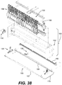
- welding assembly 160 can include welding frame assembly 162, welding units 164, and welder tracks 166.
- Welding units 164 may be movably attached to welder tracks 166, allowing welding units 164 to slide along welder tracks 166.
- Welding units 164 and welder tracks 166 are supported within welding frame assembly 162.
- the motion of one or more welding units could vary.
- the welding units may be moved as a single unit along the welder track.
- the current embodiment includes eighteen welding units that all translate together along welder tracks 166.
- the welding units may be configured in groupings of welding units, where each group is capable of moving independently of other groups.
- eighteen welding units may be configured in three groups of six welding units such that each group of welding units can be translated independently of the remaining two groups.
- each welding unit could be configured to move independently of all other welding units. Any methods known in the art could be used to move welding units.
- the welding units could each include a motor that drives the unit along a track or screw drive.
- welding unit 450 may include welding device 452, which further includes welding tip 454. Welding unit 450 may also include pressure foot 456 that is arranged around welding tip 454. In some cases, welding unit 450 may also include backing plate 462 that is used to secure welding device 452 to a welding assembly.
- welding unit 450 can include extension spring 458 that provides a restoring force to return welding device 452 to a default raised position following the extension of welding device 452. In some cases, welding unit 450 may be moved in a vertical direction using a pneumatic cylinder with an internal guide. Extension spring 458 may also help retain welding unit 450 in a raised position if air pressure in the system is lost. Additionally, in some cases, welding unit 450 can include tracks 460 that help manage wires and other utility connections as welding unit 450 translates in the vertical direction.
- welding device 452 may translate downwardly with respect to backing plate 462.
- pressure foot 456 may contact any underlying tape material in order to apply a contact pressure to the tape material and hold it against the vacuum table or previously laid tape sections.
- welding device 452 may energize and apply the weld at the contacting location.
- welding device 452, along with pressure foot 456, may be retracted with the assistance of spring 458.
- This arrangement for the welding units may integrate vertical movement of the pressure foot and welding device.
- the arrangement of the pressure foot 456 in the current design may provide the ability to hold the tape in place on either side of the welding tip 454 during the ultrasonic weld.
- the welding assembly of the embodiments described in this detailed description may provide improved operation over some alternative designs.
- the customized welding units provide tighter tolerances, faster operation, and lower cost when compared to some traditional units.
- tape section guide 170 may include first guide support 167 and second guide support 168, collectively referred to as tape guide supports 169.
- Tape guide supports 169 may help direct tape sections along the length of welding assembly 160.
- tape guide supports 169 may include grooves that receive the edges of a tape section and allow the tape section to be suspended over the vacuum table / tooling surface.
- An example of a suitable grooved design has already been disclosed above with reference to Figure 13 .
- alternative embodiments could incorporate other methods for holding the tape material between adjacent guide supports.
- the grooves could be removed and replaced with a plurality of small pinch rollers that line the edges of the tape support guides.
- pinch rollers could grasp the side edges of the tape material in order to transport the tape material through tape section guide 170.
- an additional gripping system that grasps the leading edge of the tape material could be optional, as the tape could be moved within tape section guide 170 using only driven pinch rollers in some cases.
- Tape section guide 170 further includes tape gripping assembly 180.
- Gripping assembly 180 shown in further detail in Figures 41 and 42 , may include track member 182, cable tray 184, and track arm 186.
- Track member 182 may comprise a driven belt supported by a guide rail or track.
- the driven belt may be powered by motor 183.
- Power chain 184 moves with track arm 186 and delivers power and air to the gripper unit 190.
- Gripping assembly 180 further includes gripping member 190.
- gripping member 190 is configured to grip an edge or other portion of the tape so that the tape can be pulled to various positions along tape section guide 170 and welding assembly 160.
- gripping member 190 can include gripping foot 192 and gripping nose 194 for grasping a portion of tape.
- gripping member 190 may be attached to track member 182 at track arm 186 so that gripping member 190 can slide along track member 182.
- the relative position of gripping member 190 with respect to tape material or a tape section could vary.
- gripping member 190 could change between different states corresponding to different tape widths.
- gripping member 190 can move between a narrow state in which gripping foot 192 and gripping nose 194 are approximately aligned along a center of relatively narrow tape sections and a wide state in which gripping foot 192 and gripping nose 194 are approximately aligned along a center of relatively wide tape sections.
- This change in state could occur, for example, by extending pneumatic cylinder 195 outwardly from track arm 186, which in turn moves gripping foot 192 and gripping nose 194.
- Tape sections may be created as tape is transported from automatic tape loading system 199 to tape placement head 103.
- gripping member 190 may grip the tape.
- a mechanism that feeds the tape e.g., pinch rollers
- the gripping member 190 may then move the tape between, and in a direction generally parallel to, first guide support 167 and second guide support 168 (see Figure 37 ) until the distance between the tape end and the cutting system 150 equals the desired strip length. Once this point has been reached, the gripping member 190 stops and holds the tape in place while the cutting system 150 cuts the tape.
- the gripping member 190 can move the newly cut tape section to another position within guide supports 169. Alternatively, if the cutting system 150 is sufficiently rapid, the gripping member 190 may not have to stop for the cutting of the tape.
- first guide support 167 and second guide support 168 may include provisions for guiding, supporting, and/or suspending the tape between welding assembly 160 and vacuum table 104.
- tape section guide 170 may include provisions for raising and lowering first guide support 167 and second guide support 168, such as guide motion devices 135 (see Figure 38 ), which connect tape section guide 170 with welding frame assembly 162.
- the spacing, or width, between first guide support 167 and second guide support 168 can be automatically adjusted to accommodate varying tape widths. This automatic width adjustment could be achieved using guide motion devices 135 or any other devices or systems.
- support guides 169 may be mounted to horizontal tracks of guide motion devices 135 that allow for horizontal or width-wise adjustment.
- support guides 169 may be mounted to guide motion devices 135 in a manner that allows tape section guide 170 to be raised and lowered with respect to the vacuum table.
- Automatic width adjustment of the guide system allows for the system to automatically switch between tape of different materials and widths without operator intervention, thus improving the efficiency and through-put time of the system.
- the configuration may also allow for automatic alignment of all components. In particular, this configuration may allow for improved consistency of placement by eliminating the inherent variations resulting from different operators setting up and adjusting the machinery.
- the configuration may also improve the ability of the system to run material with less stringent slitting tolerances.
- the machine could automatically adjust the guide supports to the actual tape width and automatically adjust the tape placement location to minimize gaps and overlaps between tape sections.
- Figure 45 some embodiments may include provisions to monitor the operation of the system, including tape dispensing and tape loading aspects, as well as for monitoring the operation of a gripping system.
- Figure 45 is used to indicate the approximate locations of some sensors that could be used for these purposes.
- First diameter sensor 502 and second diameter sensor 504 may be configured to monitor the operation of spindle 118 and spindle 119, respectively.
- these diameter sensors may be used to measure the tape roll diameter.
- the tape roll diameter may be used for input to closed-loop control of driver roller assembly 480 and driver roller assembly 490.
- tape tension sensor 510 and tape tension sensor 512 which monitor tension in the idler rollers of roller assembly 120, may be used to adjust the unwind speed of the creel unit to achieve the desired back tension.
- dancer roller 121 and dancer roller 122 could be operated to adjust tension levels in response to information gathered from the tension sensors.
- the system can also include pre-feed roller sensor 520 and pre-feed roller sensor 522, associated with first tape feed unit 402 and second tape feed unit 404, respectively, which may detect when tape is loaded into the automatic tape loading system 199.
- feed roller sensors may also detect when the end of the tape roll has been reached.
- post feed roller sensor 531 and post feed roller sensor 533 (see Figure 48 ) measure the presence of the tape after the corresponding feed rollers. The approximate locations of post feed roller sensor 531 and post feed roller sensor 533 are indicated generally as region 530 and region 532 in Figure 45 , while a more detailed view of exemplary locations for these sensors is shown in Figure 48 .
- Information from these sensors may be used to determine when the tape is retracted from the cutter unit before changing the active spool and to locate the front end of the tape. Knowing the location of the end of the tape ensures that the correct amount is fed forward to the gripper during the initial tape feed in order to avoid as much slow forward feed correction as possible.
- Some embodiments can also include sensor 540 that is associated with gripping member 190. Information from sensor 540 can be used to determine if gripping member 190 is holding tape. This may be useful to detect possible tape dispensing problems, such as bunching or jamming, which may occur once the tape has entered tape section guide 170.
- the automatic tape loading system 199 may provide a system for positioning the leading edge of a new roll of tape in the machine and for automatically switching between tape supply rolls.
- An exemplary situation in which tape material fed into the tape positioning head is changed from the first creel (or first spindle) to the second creel (or second spindle) is now described.
- the existing tape material from first spindle 118 is retracted past post pinch roller sensor 530 to ensure that there is no tape in the tape guides or cutter unit.
- Roller assembly 120 and tape feed system 130 may move vertically to align second tape feed unit 404 with cutting system 150 and the entrance to tape placement head 103.
- the width of tape section guide 170 may also be adjusted, if necessary, to accommodate the tape material of second spindle 119.
- the pinch rollers of second tape feed unit 404 may then move the tape from the second spindle 119 past post pinch roller sensor 532, through second tape feed unit 404 and through cutting system 150.
- the new tape material from spindle 119 may be positioned for the gripping member 190 to secure the tape and begin laying out the tape in the guide rails. It will be understood that the process described here may be used to change back and forth between materials from the first material spool and the material spool.
- This configuration for automatic tape loading system 199 allows rolls to be switched without operator intervention, thus reducing the downtime of the system.
- This system also provides a means of automatically making blanks comprising multiple materials (such as a blank with both carbon fiber tape sections and glass reinforced tape sections) as well as a means of automatically making blanks with multiple width tapes (e.g., a blank comprising both 6 inch tape and 2 inch tape sections).
- the system provides a means for making blanks from materials of differing widths and materials.
- FIGS 46a-46g illustrate a schematic view of an exemplary system and method for handling, placing, and tacking a tape section to vacuum table 104 and/or other tape sections.
- welding assembly 160 is shown here to include five welding units 205, while the embodiments shown in Figures 38 and 39 include eighteen welding units 164.
- cutting system 150 is shown schematically here as cutting blade 204.
- the welding units shown in Figures 46a-g and 47a and 47b are shown schematically. For a more detailed view of a welding unit, refer to Figure 40 .
- gripping member 190 may be disposed in a first position 220 adjacent to cutting blade 204 and guide motion device 206. Gripping member 190 grasps the end of the tape which has been fed into tape placement head 103. In some cases, the pinch rollers of automatic tape loading system 199 may push the tape through cutting system 150 to gripping member 190. At this point, gripping member 190 may grasp the tape and the pinch rollers may release the tape before gripping member 190 begins to move. In some cases, the end of the tape may be gripped between the gripping foot 192 and the gripping nose 194 of gripping member 190 (see Figures 43 and 44 ).
- vacuum table 104 may be rotated and simultaneously translated along axis 210.
- welding units 205 may be moved on welder tracks 166 along axis 212.
- Axis 212 may be an axis approximately perpendicular to axis 210.
- gripping member 190 moves from the first position 220 to the second position 222.
- the first position 220 and the second position 222 may demarcate positions relative to tape section guide 170 and/or welding assembly 160.
- the second position 222 is selected so that the distance between gripping member 190 and cutting blade 204 corresponds to a desired length for a tape section 250.
- cutting blade 204 may cut the tape (as indicated by arrow 299) to form the desired tape section 250, as seen in Figure 46d .
- the tape section 250 comprises a length of tape with a first end portion 271 disposed at the first position 220 and a second end portion 272 disposed at the second position 222 along tape section guide 170.
- the pinch rollers may immediately clamp onto the tape material fed from automatic tape loading system 199 just prior to, simultaneously with, or very shortly after, when the tape section is cut, in order to prevent the tape material from retracting from the engaged driver roller assembly.
- gripping member 190 may move from the second position 222 to a third position 224 in order to align the tape section 250 over the desired location on vacuum table 104.
- the tape section is pulled through tape section guide 170 by gripping member 190 so that first end portion 271 is at a fourth position 223 while second end portion 272 (which is held by gripping member 190) is at third position 224.
- tape section guide 170 may be simultaneously lowered to vacuum table 104 to prepare the tape section for welding, as indicated by arrows 298.
- the tape section 250 may be tacked or welded onto vacuum table 104 or to any underlying tape sections.
- first welding unit 231 and second welding unit 232 are lowered so that first welding tip 241 and second welding tip 242 contact tape section 250 and tack the tape section 250 to vacuum table 104.
- the remaining group of adjacent welding units namely, third welding unit 233, fourth welding unit 234 and fifth welding unit 235, which are indicated in Figure 47a ) remains stationary and does not engage tape section 250.
- the tape section 250 may directly contact the vacuum table 104 and in other cases it may contact previously placed tape sections.
- the gripping member 190 can release the tape during, or just prior to, the period when the welding units 205 are engaging the tape section. This may avoid any interference by the gripping member 190 in the welding of tape sections.
- Figure 46g shows an exemplary embodiment of the tape section tacked to vacuum table 104 after guide assembly 170 and welding units 205 have been raised away from vacuum table 104.
- different methods of releasing the tape section from guide assembly 170 can be used.
- the guide rails 25 may be raised up with the pressure feet or welding tip still pressing on the tape. This causes the tape edges to be pulled out of the grooves of the guide rails 25, releasing the tape section from the guide rails 25.
- the pressure feet of the welding units may retract.
- the tape section could be released by extending the width between the guide supports and then raising the guide supports from the tooling surface.
- Figure 47a illustrates another configuration where gripping member 190 is moved to position 260 to create a predetermined length for a tape section 280.
- the tape section may then be repositioned as gripping member 190 moves to position 262, as seen in Figure 47b .
- tape section guide 170 has lowered to vacuum table 104 (represented by arrows 297) and some of welding units 205 have been lowered.
- second welding unit 232, third welding unit 233, and fourth welding unit 234 have been lowered to tack or weld the tape section while first welding unit 231 and fifth welding unit 235 remain in a raised position.
- This selective operation of the welding units which is coordinated with the length and position of the tape section, may provide more rapid and efficient manufacture.
- the motions of welding units may not be restricted to vertical motions and motions along the length of a welding assembly.
- welding units could be configured to move in a direction perpendicular to the longitudinal direction associated with a tape section guide.
- one or more welding units may move in the perpendicular direction, which could take them in and out of vertical alignment with the tape section guide.
- Such an embodiment could help in operating a single set of welding units for two or more different tape section guides arranged in parallel beneath a welding assembly.
- the system described herein provides for a wide variety of different relative motions between components and sub-systems. So, for example, the motions of welder units, the welding assembly 160, the tape section guide 170, the gripping member 190, vacuum table 104, cutting system 150 as well as other components and systems described in the embodiments, may be coordinated to achieve a desired manufacturing process and resulting manufactured parts. As one example, gripping member 190 may move along the length of welding assembly 160 substantially simultaneously with the motion of vacuum table 104, so that tape sections in the tape section guide 170 are aligned in the proper locations with respect to pre-existing tape sections on the vacuum table 104.
- the motion of the welding units may be coordinated with the motion of gripping member 190 to ensure that the welding units do not interfere with the path of gripping member 190 it pulls tape sections through tape section guide 170. Still further, in other embodiments, any sequence of relative motions between welding assembly 160, vacuum table 104, and a tape section within tape section guide 170 could be possible.
- the vacuum table 104 may serve as the tooling surface upon which the part is built up.
- the vacuum table 104 may be attached to a platform 105 that precisely positions vacuum table 104 under tape placement head 103 via translational motion along an axis approximately perpendicular to the length of tape placement head 103 as well as using rotational motion.
- welding units 164 can also be translated along an axis perpendicular to the translational axis of platform 105. Instructions from an off-line program may determine the length of tape and its position and orientation on the table.
- the ability to move the gripping member and welding units may provide for increased placement accuracy since the tape and welders can be aligned after the tape section has been formed. This arrangement can also facilitate increased course lengths, with lengths of up to 2.82 meters or even greater being possible. In addition, this configuration helps increase through-put speed by relying on the gripping member to control the feeding of the tape and the speed of tape section movement, rather than the tape speed being reliant on intrinsic properties of the tape such as stiffness to be pushed through the rails. Having the tooling surface translate in only one linear direction as opposed to two perpendicular directions may also provide a cost reduction. Additionally, the overall machine footprint can be reduced over similar designs that incorporate two linear motion axes and rotation for the tooling surface.
- the current configuration may also allow for multiple heads laying up tape simultaneously on the same ply.
- tape could be fed from either side of the tape placement head 103 to improve speed, for example, by providing material dispensers (spools and loading systems) on both first side 147 of tape placement head 103 (which is the configuration used in the illustrated embodiments) and second side 149 of tape placement head 103 (first side 147 and second side 149 of tape placement head 103 are shown in Figure 27 ).
- material dispensers spools and loading systems
- first side 147 and second side 149 of tape placement head 103 first side 147 and second side 149 of tape placement head 103 are shown in Figure 27 .
- a substantially similar configuration of spools and loading systems that are used to feed tape into first side 147 in the illustrated embodiments could be provided for feeding tape into second side 149 of tape placement head 103.
- tape placement head 103 could be configured with an additional cutting blade, gripping system as well as possibly other provisions for manipulating tape and tape sections fed into second side 149 of tape placement head 103.
- the current configuration may also improve machine robustness by improving the ability of the system to handle a wider variety of tape without feed errors.
- first guide support 167 and second guide support 168 may lower until the tape section is nearly touching a previously laid ply or the tooling surface. Then an array of one or more welding units 164 may lower from the welding assembly 160 and press the section of tape onto the tool.
- the welding units 164 may remain in contact with the tape, and the first guide support 167 and second guide support 168 may be raised to the initial load position. In some cases, the guides can be raised before the welding/tacking has been completed. Since the center of the tape remains secured to the tool and pinned down by the welder units, this causes the edges of the tape to be pulled out of tape section guide 170. Once the tape edges are free of the tape section guide 170, the welder units retract, leaving the tape section in place on the vacuum table tooling surface.
- This procedure may be repeated for each section of material that will comprise the blank. After the final tape section has been placed, the table vacuum may be turned off, which allows the part to be removed easily from the table.
- the tape section guide 170 can be configured to automatically adjust the spacing between first guide support 167 and second guide support 168 in order to accommodate tape sections of varying widths. This allows preforms to be made with tape sections of at least two different widths, for example, by loading first spindle 118 and second spindle 119 with tape rolls of differing widths. Then, as tape sections from the different spindles are fed into tape placement head 103, tape section guide 170 can automatically adjust to accommodate the different tape section widths.
- either or both of the tooling surface and guide supports move to provide relative displacement with respect to each other.
- Such movement can be in any direction, such us horizontal, vertical, or combinations thereof, and can include movements such as translational, rotational, or pivotal movements.
- Some embodiments can include provisions to enhance or otherwise fine tune aspects of welding tape sections together. Some embodiments can include provisions to prevent welds between multiple plies from being laid directly over each other, which may result in unwanted structural features for the completed composite material. In some cases, a program may be used to automatically adjust the locations of welds so that welds on different layers of the composite are staggered in the plane of the vacuum table and not positioned directly on one another in the vertical direction. Still other embodiments could include provisions for making continuous welds between two layers. For example, in one embodiment, a continuous rotary welder could be used that continuously contacts, and applies a weld, over various portions of a tape section.
- a rotary welder comprises a wheel that is attached to a gripping member. Once the gripping member has positioned a tape section within the guide system and over the desired location on the vacuum table, the rotary welder could move over some or all of the length of the tape section to apply a substantially continuous weld.
- Some embodiments can include provisions to reduce through-put time by reducing the time that the tape feed is stopped, or the time required to reposition a gripping member after a weld.
- some embodiments could include provisions to cut tape material into tape sections while the tape material continues to be fed through the system. In some cases, for example, cutting could be performed without stopping the tape feed, which may result in increased through-put speeds for the system.
- Some embodiments could include provisions that would allow a gripping member to move throughout the tape placement head even while one or more welding units are extended towards a vacuum table.
- a gripping member that is mounted to a track using a hinge-like mounting, so that the gripping member may swing up and out of the plane of the guide supports and tape section as welds are being applied.
- the gripping member could swing to a position that is disposed behind the welding units. This would allow the gripping member to move behind the welding units and towards the cutting system as welds are being applied.
- a hinging connection could be provided at portion 197 gripping member 190 (see Figure 44 ).
- portion 197 could be an inside edge of extender 195.
- extender 195, gripping foot 192 and gripping nose 184 may swing upwardly so that gripping member 190 is no longer in the path of the welding units. This would allow gripping member 190 to move to any position along track member 182 without interfering with any of the welding units 164 that may be lowered.
- the suggested location for a hinge described here is only intended to be exemplary. In other cases, a hinge or hinging connection could be disposed on any portion of gripping member 195.
- the gripping member could be mounted to a track that moves along a region between the guide supports as well as a region outside of the guide supports. This would allow the gripping member to move the tape section to a predetermined location between the guide supports, release the tape section once the tape section has been engaged by at least one welding unit, and then continue to move along the track and loop around the guide supports to a position near the cutter before the welding has been completed.
- the track would extend over a region located behind the welding units to allow the gripping member to move along the tape placement head without interfering with the welding units.
- the guide system described herein including guide supports, are only one of many means that could be used for suspending the tape above the tooling surface and positioning the tape once it has been fed and cut.
- Other methods that use vacuum to suspend the tape above the tooling surface, trays that release the tape by increasing the distance between the guide rails, retractable trays, or other mechanisms may be employed.
- the systems and methods described above allow for the capability of placing materials of different materials in a single blank. For example, one spindle could be loaded with tape made of a first material, while a second spindle could be loaded with tape made of a second material. Both materials could be fed into the guide system for forming tape sections and welding the various tape sections together.
Landscapes
- Engineering & Computer Science (AREA)
- Mechanical Engineering (AREA)
- Health & Medical Sciences (AREA)
- Toxicology (AREA)
- Robotics (AREA)
- Chemical & Material Sciences (AREA)
- Composite Materials (AREA)
- Lining Or Joining Of Plastics Or The Like (AREA)
- Moulding By Coating Moulds (AREA)
Description
- The present embodiments relate generally to advanced composites and, more particularly, to a system and method for rapidly fabricating advanced composite laminates with minimal scrap, using automated equipment.
- Advanced composite materials are increasingly used in high-performance structural products that require low weight and high strength and/or stiffness. Composite materials are engineered materials that comprise two or more components. The embodiments relate to polymer composites that combine reinforcing fibers such as carbon fiber, glass fiber, or other reinforcing fibers with a thermosetting or thermoplastic polymer resin, such as epoxy, nylon, polyester, polypropylene, or other resins. The fibers typically provide the stiffness and strength along the direction of the fiber length, and the resin provides shape and toughness and also acts to transfer load between and among the fibers. The structural performance of an advanced composite part increases with increased fiber-to-resin ratio (also called fiber volume fraction), increased fiber length, closer alignment between the fiber orientation and the load path through the part (in contrast to random fiber orientation), and the straightness of the fibers. The weight of an advanced composite part can also be optimized by selectively adding or subtracting material according to where it is highly and lightly stressed.
- Typically, the manufacture of high-performance, advanced composite parts is a slow and labor-intensive process. Thus, several approaches for automating the fabrication of advanced composite parts have been developed to reduce hand labor, decrease cycle time, and improve part quality and repeatability. Such machines are used to fabricate small and large parts ranging from aircraft fuselages and internal structural members to pressure vessels, pipes, blades for wind turbines, and wing skins. These machines typically place tape material directly on a mandrel or a mold using a material placement head mounted on a multi-axis, CNC manipulator. As the material is laid up, it is consolidated with any underlying layers. This is called "in situ" consolidation.
- A different approach, described in
U.S. Patents Nos. 6,607,626 and6,939,423 , is to lay up a substantially flat "tailored blank" where all the plies of the composite laminate are only tacked together. Once the tailored blank has been made, subsequent processing steps are used to consolidate the plies together and form the blank into its final shape. - One characteristic typical to tape and fiber placement machines is the overall technique used to apply material to a tooling surface: such machines progressively unroll a tape or tow material onto a tooling surface that is configured to match the near net shape of the part and tack it in place using one or more compaction rollers or shoes as the material is fed onto the surface. While this technique yields high quality parts, one main limitation is that increasing the material placement rate requires larger, higher power machines, which has a compounding effect on system size, energy consumption, cost, and precision. In many systems, speed is also constrained by the heat transfer rate, especially for thermoplastic composites, which are typically melted and then refrozen during placement.
- Another limitation of fiber placement and tape laying machines is that they most typically produce parts very near to the final net shape and thus the attainable part complexity and contour is governed by the size and dexterity of the manipulator to which the layup head is attached. Such systems typically require five or six degrees of freedom to produce the types of parts noted above.
-
US 2009/0101277 A1 discloses a method and an apparatus for manufacturing a composite preform from tape material including feeding a tape section into a tape section guide that suspends tape section over a tooling surface, moving the tape section guide and the tooling surface relative to each other, further moving the tape section towards a pre-existing tape section on the tooling surface and tacking the tape section. -
EP 0846551 A1 discloses a tape laying head for the manufacture of composite parts. - Embodiments provide a system and method for applying composite tape material onto a tooling surface. Instead of progressively applying tape to a tooling surface, which is configured in the net shape of the part and consolidated in-situ, embodiments place courses of tape in a substantially flat configuration suitable for post consolidation and forming operations by feeding tape material of a predetermined length and locating it above the tooling surface. The tape can be pre-cut into a tape section or can be fed (e.g., pulled) from a tape supply and cut into a tape section (or "course") of the desired length. The tape section may be moved toward the tooling surface. Once near or on the tooling surface, the entire tape section can be tacked to the underlying material in one operation. The tacking can comprise, for example, the fusing of the tape section to the underlying material at isolated locations using a spot welder or other fusing process. Separating the tape feed operation from the tacking operation may allow the system to run automatically, faster, and more reliably.
- One embodiment comprises a system and method for making high-performance, advanced composite laminates by positioning one or more tape sections over a multi-axis motion table, then lowering the tape sections onto the table and tacking them to previously laid material using an array of spot welding units.
- In one aspect, a method for manufacturing a composite preform from tape material according to the present invention includes the features of
claim 1. - In another aspect, an apparatus for manufacturing composite preforms from composite tape according to
claim 5 is presented. - Other systems, methods, features, and advantages of the embodiments will be, or will become, apparent to one of ordinary skill in the art upon examination of the following figures and detailed description.
- The embodiments can be better understood with reference to the following drawings and description. The components in the figures are not necessarily to scale, emphasis instead being placed upon illustrating the principles of the embodiments. Moreover, in the figures, like reference numerals designate corresponding parts throughout the different views.
-
Figure 1 is a schematic diagram illustrating an embodiment of a tailored blank. -
Figure 2 is a schematic diagram illustrating an isometric view of an embodiment of a system for applying composite tape. -
Figure 3 is a schematic diagram illustrating a front view of the system shown inFigure 2 . -
Figure 4 is a schematic diagram illustrating a top view of the system shown inFigure 2 . -
Figure 5 is a schematic diagram illustrating a detail view of an embodiment of a material dispensing system and tape transport rail. -
Figure 6 is a schematic diagram illustrating a detail view of an embodiment of a material dispensing system and autofeeder unit. -
Figure 7 is a schematic diagram illustrating an embodiment of a placement head. -
Figure 8 is a schematic diagram illustrating a side view of an embodiment of a feed and cutter unit with the front frame plate removed. -
Figures 9a and9b are schematic diagrams illustrating a detail view of an embodiment of a tape placement head. -
Figure 10 is a schematic diagram illustrating a detail view of an embodiment of a tape carriage. -
Figure 11 is a schematic diagram illustrating an end view of an embodiment of a carriage frame. -
Figure 12 is a schematic diagram illustrating slotted holes in an embodiment of a carriage frame. -
Figure 13 is a schematic diagram illustrating a side view of an embodiment of tape passing through the exit of the feed and cutter unit and entering the guide rails of the carriage frame. -
Figure 14 is a schematic diagram illustrating a front view of an embodiment of a welder frame unit. -
Figure 15 is a schematic diagram illustrating a front view of an embodiment of a single welder unit with a pressure foot attached. -
Figure 16 is a schematic diagram illustrating an embodiment of a configuration of an unwind and slack system. -
Figure 17 is a schematic diagram illustrating a detail view of an embodiment of a single autofeeder unit. -
Figure 18 is a schematic diagram illustrating an end view of an embodiment of a tape section cupping between guide rails and a lowered guide rail vertical location relative to a tooling surface. -
Figure 19 is a schematic diagram illustrating an end view of an embodiment of a tape section being tacked to an underlying tape section. -
Figure 20 is a schematic diagram illustrating an end view of an embodiment of a tape section being removed from guide rails as the guide rails retract and the pressure foot holds the tape section in place. -
Figure 21 is a schematic diagram illustrating an embodiment of an end view of guide rails retracted and pressure foot retracted. -
Figure 22 is a schematic diagram illustrating an embodiment of lateral movement of guide rails with an angled cutter. -
Figure 23 is a schematic diagram illustrating an embodiment of an angled cutter and horizontally actuating guide rail mechanism with the cut angle in the +45° cut position. -
Figure 24 is a schematic diagram illustrating a top view of the angled cutter and horizontally actuating guide rail mechanism ofFigure 23 , with the cut angle in the +45° cut position. -
Figure 25 is a schematic diagram illustrating a top view of the angled cutter and horizontally actuating guide rail mechanism ofFigure 23 , with the cut angle in the 0°cut position. -
Figure 26 is a schematic diagram illustrating a top view of the angled cutter and horizontally actuating guide rail mechanism ofFigure 23 , with the cut angle in the -45° cut position. -
Figure 27 is a schematic diagram illustrating another embodiment of a system for applying composite tape. -
Figure 28 is a schematic diagram illustrating a top view of the system shown inFigure 27 . -
Figure 29 is a schematic diagram illustrating a partial cross sectional view of the system shown inFigure 27 , as taken along the section line shown inFigure 28 . -
Figure 30 is a schematic diagram illustrating an embodiment of a tape dispensing system. -
Figure 31 is a schematic diagram illustrating an isometric view of an embodiment of a material drive system. -
Figure 32 is a schematic diagram illustrating a cut away view of the material drive system ofFigure 31 . -
Figure 33 is a schematic diagram illustrating an isometric exploded view of an embodiment of a chuck member for a material drive system. -
Figure 34 is a schematic diagram illustrating an isometric view of the chuck member ofFigure 33 . -
Figure 35 is a schematic diagram of an isometric view of an embodiment of an automatic tape loading system. -
Figure 36 is another isometric view of the automatic tape loading system ofFigure 35 . -
Figure 37 is a schematic diagram illustrating an embodiment of a welding system. -
Figure 38 is a schematic diagram illustrating an exploded isometric view of the welding system ofFigure 37 . -
Figure 39 is a schematic diagram illustrating an isometric view of an embodiment of a cutting system. -
Figure 40 is a schematic diagram illustrating an isometric view of an embodiment of a welding unit. -
Figure 41 is a schematic diagram illustrating a view of an embodiment of a gripping assembly. -
Figure 42 is a schematic diagram illustrating an exploded isometric view of the gripping assembly ofFigure 41 . -
Figure 43 is a schematic diagram illustrating an isometric view of an embodiment of a gripping member. -
Figure 44 is a schematic diagram illustrating an exploded isometric view of the gripping member ofFigure 43 . -
Figure 45 is a schematic diagram illustrating the locations of some sensors according to an embodiment. -
Figures 46a-46g illustrate a sequence of steps in a process for applying tape sections to a tooling surface according to one embodiment. -
Figures 47a and47b illustrate another sequence of steps in a process for applying tape sections to a tooling surface according to one embodiment. -
Figure 48 illustrates a schematic view of an embodiment of driver roller assemblies and passive roller assemblies for tape feed units. -
Figure 49 illustrates a schematic view of some components of a tape feed unit. - Embodiments provide a tape placement method. As described in detail below, the tape placement method involves locating a material placement head above a tooling surface, feeding tape into a guide that holds the tape above the tooling surface, cutting the tape from the feedstock into a tape section, moving the tape section near or onto the tooling surface, and then tacking the tape section to any underlying tape layers or securing the tape section to the tooling surface.
- The present embodiments can be used to create advanced composite preforms from tape material, such as preimpregnated fiber and polymer tape and pure polymer tape. Advanced composite materials contain reinforcing fibers, a polymer resin, and sometimes a core material such as foam or honeycomb. The part is made by stacking layers of material in one or more orientations, or ply angles. The ply angles are determined by the part's load requirements. Typically, the material that comprises the laminate will be a preimpregnated tape containing reinforcing fiber and a polymer resin. However, unreinforced polymer tape, core material, or other materials such as a metallic film could be included in the laminate based on the requirements of the application.
- The reinforcing fibers can be made from, for example, carbon, glass, basalt, aramid, polyethylene, or any other reinforcement. Like string, rope, hair, or other fibers, reinforcing fibers used in polymer composites add strength and stiffness to a part along the direction of the fiber length. The fibers are preferably continuous or near continuous in length and aligned parallel with the tape length (or longitudinal axis of the tape), but no specific reinforcement format within the tape is required. Additionally, tape comprising resin and continuous or discontinuous fibers that are not substantially aligned parallel to the edge of the tape could be used. The polymer resin can be thermoplastic (for example, polyamide, polyphenylene sulfide) or thermosetting (for example, epoxy, vinyl ester, or polyester). As with most polymer composite applications, the specific resin and fibers used and their proportion and format within the composite are determined by the specific requirements of the part to be manufactured.
- The present embodiments can be used to create a laminate comprising multiple plies of tape material. Each ply contains one or more sections of tape (also called courses) placed parallel to each other, and each ply is fused to one or more underlying plies. The shape of each ply and the orientation, or angle, of the fibers in the ply relative to fibers in other plies in the laminate are chosen such that the final produced part will have the desired structural characteristics. The first step of the method used to fabricate a tailored blank is to feed tape material of a specified length from a spool into a tape section positioning system that suspends the tape above the tooling surface upon which the tape will be placed. The second step, which could occur concurrently with step one, involves positioning the tape section relative to the tool such that when the tape section is lowered onto the tool, it is in the correct position and orientation for the part. In the third step, the guide lowers the tape section and the section is either tacked to underlying material or secured to the tool surface. Any material that directly touches the tooling surface can be secured to the tool using techniques (e.g., vacuum) that may differ from the methods used to tack tape layers to each other. Once the section of material has been secured to underlying material or to the tooling surface, the tape section locating system and tacking system return to their starting positions and a new section of material is fed into the guide. The preceding steps in the process may then be repeated until the blank is complete.
- Several variations or embodiments of this overall processing method could be employed. Though the process is described here as a series of sequential steps, embodiments of this method could execute these steps simultaneously to reduce overall processing time. For example, moving the tape section locating system and/or the tool into position could occur while the guide is raising and/or lowering and/or while the tape is being fed into the guide. Also, embodiments of this method could place more than one section at a time by incorporating additional placement heads into the machine. Therefore, nothing in this description should imply that sections necessarily be placed one at a time. Specific embodiments of the method could also include the capability to place varying widths or multiple materials in a single blank.
- In addition, alternate embodiments could involve placing tape sections that have been pre-cut rather than cutting the tape after it has been fed into the guide rails. Staging pre-cut tape before the guide rails could speed up the operation of the machine since the cut operation would be removed from the critical path in the order of machine operation. Additionally, the use of pre-cut tape sections could eliminate the requirement for dynamic tension control from the tape placement portion of the process. The tape sections could be pre-cut in line with the feed and placement, or the tape sections could be pre-cut off-line and staged as a kit to be fed into the guide rails.
- The method used to tack plies together and the degree to which they are tacked is another parameter that could vary in different embodiments. Methods for tacking the courses to underlying plies could include contact heating, ultrasonic welding, induction welding, laser heating, hot gasses, or other methods of adhering plies to each other. Also, the method could be used with an articulating head or a moving tooling surface, or a combination of the two positioning approaches. Although an embodiment described herein uses a fixed material placement head that is positioned over a substantially flat tooling surface that can move in the x and y directions as well as rotate, the relative motion between the placement head and the tooling surface could also be achieved by moving the placement head or a combination of the two.
- A specific implementation is depicted in
Figures 2-16 . This exemplary system comprises amaterial dispensing system 1,tape transport rails 2, aplacement head 3, a vacuum table 4 that serves as the blank tooling surface, a 3-axis motion table 5, and astructural beam 6. Theplacement head 3 andtape transport rails 2 are affixed to the structural beam and positioned over the motion table 5 and vacuum table 4. Additional support systems are depicted and include anoperator interface computer 7,electronics control cabinets 8, avacuum pump 9, and perimeter safety guarding 10. - As shown, for example, in
Figures 5 ,6 ,16 , and17 , thematerial dispensing system 1, also called a creel rack, contains one ormore creel boxes 35 that containtape unspooler mechanisms 11. In this system, a roll oftape 47 is loaded onto aspindle 12 and secured in place. Spool guards 13 are put in place to keep the edges of the tape aligned. The leading edge of the tape is fed around afirst guide roller 48 betweenfeed rollers 15 in acreel feed mechanism 14 and past asecond guide roller 49. One coil of the tape is then looped around the outside of the entire spool, fed around an additional set ofguide rollers 16 within the creel feed mechanism, and out to theauto feeder unit 17. Once the tape is fed into the autofeeder unit, theautofeeder pinch rollers 18 engage and feed the tape through a feed guide 19 (see, for example,Figure 17 ) and across the tape transport rails and into thetape placement head 3. Once the tape passes throughfeed rollers 23 in the tape placement head (seeFigures 9a and9b ), theserollers 23 engage and therollers 18 in the autofeeder disengage. - As shown in
Figure 7 , thetape placement head 3 has three subsystems: a tape feed andcutter unit 20, awelding unit 21, and atape carriage unit 22. Tape enters through the tape feed andcutter unit 20 and through a set of drivenfeed rollers 23. As shown, for example, inFigures 9a and9b , thefeed rollers 23 pinch the tape and push it past an adjustabletape alignment plate 44, through a tape-cuttingunit 24, and into guide rails 25 (seeFigure 10 ) that are part of thetape carriage unit 22. As shown inFigure 13 , tape is fed through the guide rails 25 until the distance between the tape end and thecutter blade 45 equals the desiredstrip length 26. Once this point has been reached, the pinch roller stops feeding tape and the cutter unit cuts the tape. This leaves a section oftape 27 of a known length suspended between the guide rails 25. - In the feed and cutter unit depicted in
Figure 8 , thecutter unit 24 comprises a blade and anvil between which the feed unit feeds the tape and whose movement is controlled such that when the blade shears past the anvil, the tape is cut into a tape section. Alternate cutter embodiments could also be used, including, for example, a rotary knife cutter, an ultrasonic knife, or a laser that could traverse a path across the width of the tape to cut it. With a traversing cutter, or similar device, the cut line could also be nonlinear, for example, curved, jagged, or serrated. - The guide rails 25 are part of the tape carriage unit 22 (see
Figures 7 and10 ). In this embodiment, the system comprises two substantiallyparallel guide rails 25 that are each attached to a set of carriage frames 28. There is one guide rail and one carriage frame for each edge of the tape. Each carriage frame is affixed to themain welder frame 29 vialinear slides 30 and alinear actuator 31. As shown inFigures 11 and 12 , slotted attachment holes 42 in thehorizontal portion 43 of the carriage frame allow the distance of the guides from centerline of thetape 48 to be adjusted. - In this embodiment, the tape section is held between the guide rails by grooves in the guide rails in which the edges of the tape rest. Tape that has a certain degree of transverse stiffness (i.e., stiffness across the width of the tape section) stays in place just by resting on the grooves. For tape with insufficient transverse stiffness to stay in the grooves, the guide rails can be moved closer together such that the tape is squeezed and becomes cupped with the center of the tape higher than its edges. The cupped shape provides additional transverse stiffness to the tape section, allowing it to be held by the guide.
-
Figures 18-21 illustrate an exemplary system and method for handling, placing, and tacking atape section 56 to an underlying tape section. In this example, thetape section 56 has insufficient transverse stiffness to remain in the grooves simply by resting on top of the lower surface of the grooves in the guide rails 25. Therefore, the guide rails 25 are adjusted to be closer together such that the edges of thetape section 56 are squeezed by the vertical walls of the grooves, causing thetape section 56 to become cupped with the center of the tape section higher than itsedges 53, as illustrated inFigure 18 . In other words, the width of thetape section 56 is convex with respect to horizontal inFigure 18 . The cupped shape provides additional transverse stiffness to the tape section, allowing it to be adequately supported by the grooves in the guide rails 25. - With the
tape section 56 within the guide rails 25, the guide rails 25 lower to a point just above thetooling surface 4, as illustrated inFigure 18 . Next, as illustrated inFigure 19 , one ormore pressure feet 54 lower to press thetape section 56 into contact with the underlying material. In the present embodiment, thewelder tips 46 themselves (seeFigure 15 ) serve as pressure feet, in addition to thededicated pressure feet 33 that have also been described. Alternatively, the welder tips and pressure feet can be a single integrated device. With the tape in place and the welder tips lowered, the tape section is then tack welded to any underlying material. In some cases, the tape section will directly contact thetooling surface 4 and in other cases it will contact previously placedtape sections 55. If the tape section underneath a welder tip is directly touching the tooling surface, then that particular welder does not energize, since that portion of the tape section is secured to the table, for example, with vacuum. - Once the welds have been made, as illustrated in
Figure 20 , the guide rails 25 rise up with the pressure feet still pressing on the tape. This causes the tape edges to be pulled out of the grooves of the guide rails 25, thus releasing thetape section 56 from the guide rails 25. Then, as illustrated inFigure 21 , the pressure feet retract, leaving thetape section 56 secured in place on thetooling surface 4. - In this embodiment, the vacuum table 4 serves as the tooling surface upon which the part is built up. The vacuum table is attached to a three-axis motion platform 5 (see
Figures 2 ,3 , and4 ) that precisely positions the vacuum table beneath the placement head. Instructions from an off-line program determine the required length of tape and its position and orientation on the table. While the tape is being fed into the guide rails 25, themotion platform 5 moves the vacuum table 4 under the placement head to the desired x-axis, y-axis, and rotary angle coordinates. In other embodiments, the tooling surface may not be a vacuum table. In some cases, for example, an electrostatic charge could be used to hold tape sections or other parts to a tooling surface. Moreover, any methods known in the art for holding material to a tooling surface could be used in still other embodiments. - Having described the configuration and function of each of the subsystems above, the entire tape placement process operates as follows:
- Once the tape has been fed into the guide rails 25 and cut from the roll into a tape section, and the vacuum table 4 has been positioned at the desired location and orientation, the carriage frames 28 lower until the tape section is nearly touching either a previously laid ply or the tooling surface. An array of one or more welder units then lowers from the
welding unit 21 and presses the section of tape onto the tool (or previously laid ply). For reference, three six-welder units are illustrated inFigures 2 ,4 , and7 . In addition to thewelder tip 46, apressure foot 33 is attached to each welder actuator (see, for example,Figures 14 and15 ). This pressure foot also serves to press down on the tape to hold it in contact with either thetooling surface 4 or a previously laid ply. - For the condition where the tape section is placed in direct contact with the
tooling surface 4, it may be held in place by the table's vacuum. For the condition where the tape section is placed on top of a previously laid ply, the welder may turn on and tack the top layer of tape to the underlying material. In one embodiment, the welders may use an ultrasonic impulse to create these welds. - When the welding / tacking step is complete, the welder units remain in contact with the tape while the carriage frame begins to lift up and return to its load position. Since the center of the tape remains secured to the tool and is pinned down by the welder units, the relative motion between the stationary tape section and the rising
guide rails 25 causes the edges of the tape to be pulled out of the guide rails 25. Once the tape edges are free of the guide rails 25, the welder units retract, leaving the tape section in place on thetooling surface 4. - This procedure is repeated for each section of material that will comprise the blank. After the final tape section has been placed, the table vacuum is turned off, which allows the part to be removed easily from the table.
- For the
placement head 3 to feed tape quickly into the guide rails 25, the tape may be configured to have very low back tension. If the tension is too high, the inertia of the spool of material could resist the rapid acceleration and deceleration of the tape as the feed rollers push tape into position. Thus, as shown inFigure 16 , thematerial dispensing system 1 actively unspools the material roll so that it puts slack in the final loop ofmaterial 34 within thecreel box 35. The amount of slack is determined by the length of the tape section to be placed. This slack loop leaves very little back tension in the tape and allows the placement head to feed material very quickly. Sensors within thecreel box 36 inform the control system if the slack loop is getting too small or too large. - The pinch roller can feed tape from a spool into a slack coil of tape within a creel box and can be configured to maintain the slack loop size to within a determined range using feedback by one or more slack loop position sensors. Maintaining slack at the end of a tape spool reduces back tension in the tape as the tape feeds. Actively uncoiling the tape spools of the tape supply unit minimizes tape tension between the tape feed unit and the tape spools.
- During operation, several events can interrupt the normal sequence of actions. Several sensors are put in place to flag such events and to manage them. One such event is the feed roller failing to feed the correct amount of tape. This has been addressed by incorporating an encoder wheel 37 (
Figure 9a ) that measures the length of tape being fed. If the measured feed length does not agree within a certain tolerance to the desired feed length, then corrective action is taken. - The system also senses when the end of the roll of material has been reached. When the end of the roll is reached, a sensor 38 (
Figure 17 ) in theautofeeder unit 17 detects the end of the tape. The system continues to feed the tape until a second material detection sensor 39 (Figure 8 ) at the entrance to theplacement head 3 detects the tape end. When the tape end passes this point, the feed roller stops and aredirect plate 40 within the placement head is engaged, deflecting the tape end downward. The motion platform then moves the vacuum table 4 out from under the placement head and thefeed roller 23 reverses its motion, thereby feeding the final strip of tape into a catch basin 41 (seeFigure 2 ). If the second creel box is loaded with the same type and size of tape, the system can then run the autofeeder to load the placement head with new material and operation can continue without further delay. - The second creel box can be used for more than one purpose. If the tailored blank includes more than one type of tape material (for example, glass fiber tape and carbon fiber tape), then the creel boxes could be loaded with different materials. The placement head would then be able to lay up two types of material without having to be reloaded manually. The pinch rollers in the autofeeder unit of one creel box would retract tape a sufficient distance so that tape from the other creel box could be fed into the placement head.
- In the embodiment described herein, the machine can be set up to process different tape widths. To change widths of tape to process, adjustment is made to the creel boxes so that the centerline of the tape roll is aligned with the centerline of the welder tips. The distances between the guide edges of the feed guides, tape transport rails, and carriage frame are then widened or narrowed to accommodate the desired tape width. In one embodiment, the adjustments are made manually. Another embodiment employs automatic width adjustment. This automatic adjustment can reduce the time required to set the equipment up to run different widths of material. Additionally, the automatic adjustment mechanism can allow multiple tape widths to be laid up in a single blank without interrupting production to adjust the equipment.
- An alternative embodiment adds the ability to cut tape so that the cut edge is not always perpendicular to the sides of the tape. Adding the ability to vary the cut angle can give tailored blanks more degrees of freedom, which can in turn lead to improved blank performance, as well as reduce the amount of scrap to be trimmed. An exemplary angled cutting system is illustrated in
Figures 22-26 , according to an embodiment. In this system,cutter unit 50 rotates about its center andguide rails 51 each move forward and backward to maintain a close distance between thecut edge 52 of thetape section 27 and the guide rails 51. In the embodiment depicted, the horizontal movement is achieved by adding horizontally-orientedlinear slides 57 and actuators to thewelder frame 59 upon which the vertically orientedlinear slides 58 and actuators are mounted. When the cutter unit rotates to a specified angle (the system configuration at three different angles are depicted inFigures 24-26 ), one side of the cutter moves toward the guide rails and the other side moves away from the guide rails. This movement can be matched by the guide rails to maintain a minimum gap between the cutter and the rails. Maintaining a minimal gap ensures that only a small portion of the tape section overhangs the guide rails, and prevents the end of the tape section from sagging off the end of the guide rails and hindering the handling of the tape section. - Another variant of the system described includes a carriage system that moves the guide rails not only vertically, but also horizontally along the tape feed direction. This movement allows more precise positioning of the tape relative to the welder heads, and it allows for courses to be placed that are shorter than the distance between the cutter blade and the first welder head. After the cutter cuts a tape section, and the tape is within the guide rails, the carriage moves horizontally away from the cutter and lowers toward the tooling surface to deposit the tape section. Lateral guide rail movement is thus included as an independent concept, though it may also be a feature of the angled cutting system.
- In an embodiment, either or both of the tooling surface and guide rails move to provide relative displacement with respect to each other. Such movement can be in any direction, such us horizontal, vertical, or combinations thereof, and can include movements such as translational, rotational, or pivotal movements.
- As one of ordinary skill in the art would appreciate, the guide rails described herein are only one of many means that could be used for suspending the tape above the tooling surface and positioning the tape once it has been fed and cut. Other methods that use vacuum to suspend the tape above the tooling surface, trays that release the tape by increasing the distance between the guide rails, retractable trays, or other mechanisms may also be employed.
- A method and system for creating advanced composite tailored blanks using tape can include provisions for automatically adapting to different kinds of tape material characteristics and/or sizes. For example, a method and system can include provisions to guide tape sections over a tooling surface that can be used with tapes of varying degrees of stiffness. In some embodiments, a method and system may include tape spools that are unwound using a direct-drive motor. In such cases, back tensioning of the tape could be managed using various types of rollers, including dancer rollers.
- In some embodiments, a method and system can include a tape gripping assembly that grips tape supplied to a tape tacking device. The tape gripping assembly may grip an end portion of a tape and pull the tape from a tape supply to a desired length at which the tape is cut into a tape section. This "pull configuration" contrasts with "push configurations," such as embodiments described above that push tape from tape supplies into tape section guides using, for example, pinch rollers. In some embodiments of the pull configuration, tape may be pushed (e.g., by a pinch roller) far enough through the cutter so that the gripper assembly can grab an end portion of the tape, at which point the tape is no longer pushed (e.g., released by the pinch roller) and gripper assembly pulls the tape the rest of the way. The pull configuration may enable more accurate and reliable feeding of the tape and faster through-put speeds for the system.
-
Figures 27-49 illustrate different views of additional embodiments of a system for creating advanced composite tailored blanks. Some provisions of these additional embodiments may be similar to provisions disclosed with reference to the embodiments shown inFigures 1-26 . For purposes of clarity, like numerals are used to denote like parts. However, the embodiments illustrated inFigures 27-49 may include additional provisions not used in the previous embodiments. Likewise, the present embodiments may exclude some provisions used in the previous embodiments shown inFigures 1-26 . It will also be understood that still other embodiments could include combinations of provisions from the embodiments shown inFigures 1-26 and the embodiments shown inFigures 27-49 . - The process of creating a laminate comprising multiple plies of tape material may generally proceed in a similar manner as described above with some variations. In particular, during a first step the tape material may be fed from spools to a tape placement head. In the current embodiment, the tape may be unwound from the spools using a motor drive and driven pinch rollers and back tension may be controlled using dancer rollers. Tape may be fed through a tape cutting system and gripped at an end portion by a tape gripping assembly. A mechanism used to feed the tape through the tape cutting system (e.g., pinch rollers that push the tape) may release the tape after the tape gripping assembly grips the tape. Next, the tape gripping assembly may pull the tape from the tape supply to a desired length at which the tape may be cut by the cutting system to create a tape section. Next, with respect to the tooling surface, a tape gripping assembly may be used to move the tape section along the length of a tape tacking device, such as a welding system. In addition, the tooling surface can be moved along a first axis that is perpendicular to the length of the tape tacking device, as well as rotated. In some cases, the tape tacking device may also be configured to move in the direction parallel with the length of the tape tacking device. In some cases, the tape tacking device can be lowered towards the tooling surface as the tape section is positioned. At this point, the tape section may be either tacked to underlying material or secured to the tooling surface.
- Referring to
Figures 27-29 , one embodiment of the system may comprisematerial dispensing system 101,tape placement head 103, vacuum table 104 that serves as the blank tooling surface, motion table 105, andstructural beam 106. Thematerial dispensing system 101 andtape placement head 103 may be affixed to thestructural beam 106 and positioned over the motion table 105 and vacuum table 104. As shown, additional support systems may include anoperator interface computer 107, anelectronic control cabinet 108,vacuum system 109, and perimeter safety guarding 110. - In the current embodiment,
material dispensing system 101 may provide an alternative dispensing configuration to thematerial dispensing system 1 shown inFigures 2 through 5 . It will be understood however, thatmaterial dispensing system 101 is only intended to be exemplary and in other embodiments any other type of material dispensing system could be used. In particular, any system configured to store and/or deliver tape totape placement head 103 could be used. A material dispensing system could be configured to dispense tape from rollers or to dispense pre-cut tape sections. - As shown, for example, in
Figures 29 and30 , thematerial dispensing system 101 may includespindles 112. In this system, a roll of tape may be loaded ontospindles 112, includingfirst spindle 118 andsecond spindle 119, and secured in place. In some cases,spool guards 113 could be used to keep the edges of the tape aligned. In other cases,spindles 112 could be used without any spool guards. The end of the tape may then be fed through automatictape loading system 199, which may includeroller assembly 120 as well astape feed system 130 as discussed in further detail below. As described below,tape feed system 130 may include at least two separate tape feed assemblies, as well as corresponding motors. -
Figures 31 through 34 illustrate various views of one possible embodiment ofmaterial drive system 300.Material drive system 300 may includespindle 118 as well as provisions for fixing the spool of tape tospindle 118. In some cases, the spool of tape may be placed ontochuck member 302 ofmaterial drive system 300.Chuck member 302 may be configured to hold the tape spool in place and have the capability to react to the high inertial acceleration and deceleration loads of the roll that may occur as the tape is unspooled. - Referring to
Figures 32 through 34 ,chuck member 302 may include spoolingbase 304 andsleeve member 306. In some cases,sleeve member 306 may further includeplate 307 that contacts compression springs 308.Plate 307 is shown as exploded out fromsleeve member 306 inFigure 33 in order to show the alignment of various recessedportions 309 ofplate 307 with compression springs 308. In some cases, compression springs 308 may biassleeve member 306 in a default position.Wedge members 310 ofchuck member 302 extend outwardly fromslots 312, thereby applying an outward contact force for gripping the tape roll. - In some cases, in order to retract
wedge members 310 and remove and/or replace the tape roll,sleeve member 306 may be moved axially within spoolingbase 304 so as to compresssprings 308. This allowswedge members 310 to retract withinslots 312, thereby relieving their grip on the tape spool. For example, in one embodiment,pneumatic actuators 320 extendpressure plate 322 to press against posts 324. Theposts 324 may then in turn translatesleeve member 306 in an axially outward direction along spoolingbase 304 providing clearance forwedge members 310 to retract intorecess 330 ofsleeve member 306. Recess 330 may be a region of reduced diameter forsleeve member 306. Withwedge members 310 retracted, a tape roll can be removed and/or installed. In situations where no tape roll is present, thewedge members 310 may contact a hard stop in order to limit their travel. - In order to extend the
wedge members 310 and thereby lock the material roll in place onspindle 118, the pneumatic actuators may release the pressure and allow compression springs 308 to slidesleeve member 306 in an axially inward direction, untilsleeve member 306 is returned to a default position. Withsleeve member 306 in this default position,wedge members 310 may be displaced out ofrecess 330 and extend outwardly from spoolingbase 304. In some cases,wedge members 310 includeangled portions 311 that facilitate guiding of both axial and radial translations ofwedge members 310 relative to the axial motion ofsleeve member 306. - In some embodiments, to enhance the contacting forces between
chuck member 302 and a tape spool,wedge members 310 can include features that enhance traction or grip with the tape roll. For example, in some cases,wedge members 310 can include teeth and/or knurls in the surfaces that grip the tape spool. In still other cases,wedge members 310 can include pads or similar materials having relatively high coefficients of friction for the purpose of enhancing their capability to grip a tape spool. - This configuration for
chuck member 302 may facilitate quick material loading and helps to keep the tape rolls aligned in a concentric manner along the axis of rotation. Additionally, this configuration can respond to the high torque loads that may need to be applied in order to quickly accelerate the spool of tape. Furthermore, this design may allow for compatibility with standard cardboard cores that may be commonly used and purchased from tape suppliers. By using compression springs to generate forces inside the spool, rather than air pressure, the current design may improve robustness and have more consistent performance over time. - Referring now to
Figures 30 ,35 ,36 ,48 , and49 , an automatictape loading system 199 may includeroller assembly 120, which may compriseidler rollers 126 as well asfirst dancer roller 121 andsecond dancer roller 122. For example, tape fromfirst spindle 118 may be fed aroundfirst idler roller 127, aroundfirst dancer roller 121 and aroundsecond idler roller 128 and then intotape feed system 130. - In order for
tape feed system 130 to feed tape quickly, the tape may be configured to have very low back tension. Without active tension control, the inertia of the spool of material could resist the rapid acceleration and deceleration of the tape as the gripping assembly pulls the tape into position. To control back tension, the current embodiment may utilizefirst dancer roller 121 andsecond dancer roller 122, which may move in order to minimize back tension along the tape. Using dancer rollers to manage back tension may make loading the system with tape more convenient when compared to previous designs. Moreover, the dancer rollers may be used by the system to maintain constant tension while allowing for a difference in acceleration rates between the tape feeding through the pinch roller system and the material being unwound from the material spool by the chuck member. -
Tape feed system 130 may further include firsttape feed unit 402 and secondtape feed unit 404. Firsttape feed unit 402 may include firstpinch roller assembly 420 and secondtape feed unit 404 may include secondpinch roller assembly 422, which are most clearly illustrated inFigures 48 and49 . Firstpinch roller assembly 420 may includedriver roller assembly 480 andpassive roller assembly 482.Driver roller assembly 480 may be attached tomotor 484, whilepassive roller assembly 482 may be associated withair cylinder assembly 488. In an unengaged position,passive roller assembly 482 is retracted and does not press againstdriver roller assembly 480. In an engaged position,air cylinder assembly 488 actuates so thatpassive roller assembly 482 is pressed againstdriver roller assembly 480. Secondpinch roller assembly 422 may operate in a similar manner usingdriver roller assembly 490 andpassive roller assembly 492. In some cases, for example,driver roller assembly 490 is powered usingmotor 485. Moreover, firstpinch roller assembly 420 and secondpinch roller assembly 422 may be associated with firsttape feed guide 410 and secondtape feed guide 428, respectively. In some cases, as seen inFigures 35 ,36 , and49 , firsttape feed guide 410 and secondtape feed guide 428 may be aligned with firstpinch roller assembly 420 and secondpinch roller assembly 422. With this arrangement, the tape may be fed through either firsttape feed unit 402 or secondtape feed unit 404 in order to be aligned with tape cutting system 150 (seeFigures 38 and39 ). - In some embodiments, components of automatic
tape loading system 199 may be mounted toplate 430. In some cases,plate 430 may be translated vertically in order to align either firsttape feed unit 402 or secondtape feed unit 404 with cuttingsystem 150, according to which spool is currently in use. This arrangement allows a single cutting system to be used with tape from either spindle. - Referring now to
Figures 37 through 39 ,tape placement head 103 may include several subsystems: cuttingsystem 150,welding assembly 160, andtape section guide 170. Cuttingsystem 150 could include any provisions for cutting tape. Cuttingsystem 150 may comprise a blade and anvil between which the automatictape loading system 199 feeds tape and whose movement is controlled such that when the blade shears past the anvil, the tape is cut into a tape section. As shown inFigure 39 , one embodiment of cuttingsystem 150 may include cuttinganvil 153, acutting slot 154, a blade mounting 156, andanvil brackets 157. A blade may be configured to move throughanvil 153 to cut tape inserted throughslot 154. In some cases, a carbide cutting edge is associated withslot 154 in order to facilitate cutting. Alternative cutter embodiments could also be used, including for example, a rotary knife cutter, an ultrasonic knife, or a laser that could traverse a path across the width of the tape to cut it. With a traversing cutter, or similar device, the cut line could also be nonlinear, for example, curved, jagged, or serrated. - Referring back to
Figures 37 and38 ,welding assembly 160 can includewelding frame assembly 162,welding units 164, and welder tracks 166. Weldingunits 164 may be movably attached to weldertracks 166, allowingwelding units 164 to slide along welder tracks 166. Weldingunits 164 and welder tracks 166 are supported withinwelding frame assembly 162. - In different embodiments, the motion of one or more welding units could vary. In some embodiments, the welding units may be moved as a single unit along the welder track. As one example, the current embodiment includes eighteen welding units that all translate together along welder tracks 166. In other embodiments, the welding units may be configured in groupings of welding units, where each group is capable of moving independently of other groups. For example, in another embodiment, eighteen welding units may be configured in three groups of six welding units such that each group of welding units can be translated independently of the remaining two groups. In still other embodiments, each welding unit could be configured to move independently of all other welding units. Any methods known in the art could be used to move welding units. For example, in an embodiment where each welding unit moves independently from all other welding units, the welding units could each include a motor that drives the unit along a track or screw drive.
- Referring to
Figure 40 , anexemplary welding unit 450 is shown in isolation for purposes of illustration.Welding unit 450 may includewelding device 452, which further includeswelding tip 454.Welding unit 450 may also includepressure foot 456 that is arranged aroundwelding tip 454. In some cases,welding unit 450 may also includebacking plate 462 that is used to securewelding device 452 to a welding assembly. In order to facilitate vertical motion,welding unit 450 can includeextension spring 458 that provides a restoring force to returnwelding device 452 to a default raised position following the extension ofwelding device 452. In some cases,welding unit 450 may be moved in a vertical direction using a pneumatic cylinder with an internal guide.Extension spring 458 may also help retainwelding unit 450 in a raised position if air pressure in the system is lost. Additionally, in some cases,welding unit 450 can includetracks 460 that help manage wires and other utility connections aswelding unit 450 translates in the vertical direction. - In some cases, to implement a weld using
welding unit 450,welding device 452 may translate downwardly with respect tobacking plate 462. Aswelding device 452 moves downwardly,pressure foot 456 may contact any underlying tape material in order to apply a contact pressure to the tape material and hold it against the vacuum table or previously laid tape sections. Aswelding tip 454 contacts the tape material,welding device 452 may energize and apply the weld at the contacting location. Following this,welding device 452, along withpressure foot 456, may be retracted with the assistance ofspring 458. This arrangement for the welding units may integrate vertical movement of the pressure foot and welding device. Moreover, the arrangement of thepressure foot 456 in the current design may provide the ability to hold the tape in place on either side of thewelding tip 454 during the ultrasonic weld. - The welding assembly of the embodiments described in this detailed description may provide improved operation over some alternative designs. For example, the customized welding units provide tighter tolerances, faster operation, and lower cost when compared to some traditional units.
- As illustrated in
Figure 38 ,tape section guide 170 may includefirst guide support 167 andsecond guide support 168, collectively referred to as tape guide supports 169. Tape guide supports 169 may help direct tape sections along the length ofwelding assembly 160. In some embodiments, tape guide supports 169 may include grooves that receive the edges of a tape section and allow the tape section to be suspended over the vacuum table / tooling surface. An example of a suitable grooved design has already been disclosed above with reference toFigure 13 . However, alternative embodiments could incorporate other methods for holding the tape material between adjacent guide supports. In another embodiment, for example, the grooves could be removed and replaced with a plurality of small pinch rollers that line the edges of the tape support guides. These pinch rollers could grasp the side edges of the tape material in order to transport the tape material throughtape section guide 170. In such an embodiment, an additional gripping system that grasps the leading edge of the tape material could be optional, as the tape could be moved withintape section guide 170 using only driven pinch rollers in some cases. -
Tape section guide 170 further includestape gripping assembly 180. Grippingassembly 180, shown in further detail inFigures 41 and 42 , may includetrack member 182,cable tray 184, andtrack arm 186.Track member 182 may comprise a driven belt supported by a guide rail or track. The driven belt may be powered bymotor 183.Power chain 184 moves withtrack arm 186 and delivers power and air to thegripper unit 190. - Gripping
assembly 180 further includes grippingmember 190. As shown inFigures 43 and44 , grippingmember 190 is configured to grip an edge or other portion of the tape so that the tape can be pulled to various positions alongtape section guide 170 andwelding assembly 160. In some cases, grippingmember 190 can includegripping foot 192 andgripping nose 194 for grasping a portion of tape. Moreover, grippingmember 190 may be attached to trackmember 182 attrack arm 186 so that grippingmember 190 can slide alongtrack member 182. - In some cases, the relative position of gripping
member 190 with respect to tape material or a tape section could vary. For example, as the width of the tape is adjusted, grippingmember 190 could change between different states corresponding to different tape widths. In particular, in one embodiment, grippingmember 190 can move between a narrow state in which grippingfoot 192 andgripping nose 194 are approximately aligned along a center of relatively narrow tape sections and a wide state in which grippingfoot 192 andgripping nose 194 are approximately aligned along a center of relatively wide tape sections. This change in state could occur, for example, by extendingpneumatic cylinder 195 outwardly fromtrack arm 186, which in turn movesgripping foot 192 andgripping nose 194. - Tape sections may be created as tape is transported from automatic
tape loading system 199 totape placement head 103. As the end of the tape moves through cutting system 150 (e.g., pushed by pinch rollers), grippingmember 190 may grip the tape. A mechanism that feeds the tape (e.g., pinch rollers) may release the tape after the grippingmember 190 grips the tape. The grippingmember 190 may then move the tape between, and in a direction generally parallel to,first guide support 167 and second guide support 168 (seeFigure 37 ) until the distance between the tape end and thecutting system 150 equals the desired strip length. Once this point has been reached, the grippingmember 190 stops and holds the tape in place while thecutting system 150 cuts the tape. This creates a tape section of a known length suspended withintape section guide 170. Following this, the grippingmember 190 can move the newly cut tape section to another position within guide supports 169. Alternatively, if thecutting system 150 is sufficiently rapid, the grippingmember 190 may not have to stop for the cutting of the tape. - In some embodiments,
first guide support 167 andsecond guide support 168 may include provisions for guiding, supporting, and/or suspending the tape betweenwelding assembly 160 and vacuum table 104. In some cases,tape section guide 170 may include provisions for raising and loweringfirst guide support 167 andsecond guide support 168, such as guide motion devices 135 (seeFigure 38 ), which connecttape section guide 170 withwelding frame assembly 162. Additionally, in some cases, the spacing, or width, betweenfirst guide support 167 andsecond guide support 168 can be automatically adjusted to accommodate varying tape widths. This automatic width adjustment could be achieved usingguide motion devices 135 or any other devices or systems. In some cases, support guides 169 may be mounted to horizontal tracks ofguide motion devices 135 that allow for horizontal or width-wise adjustment. In addition, in some cases, support guides 169 may be mounted to guidemotion devices 135 in a manner that allowstape section guide 170 to be raised and lowered with respect to the vacuum table. - Automatic width adjustment of the guide system allows for the system to automatically switch between tape of different materials and widths without operator intervention, thus improving the efficiency and through-put time of the system. The configuration may also allow for automatic alignment of all components. In particular, this configuration may allow for improved consistency of placement by eliminating the inherent variations resulting from different operators setting up and adjusting the machinery. The configuration may also improve the ability of the system to run material with less stringent slitting tolerances. In other embodiments in which in-line width measurements may be added to the system, the machine could automatically adjust the guide supports to the actual tape width and automatically adjust the tape placement location to minimize gaps and overlaps between tape sections.
- Referring now to
Figure 45 , some embodiments may include provisions to monitor the operation of the system, including tape dispensing and tape loading aspects, as well as for monitoring the operation of a gripping system. For purposes of clarity,Figure 45 is used to indicate the approximate locations of some sensors that could be used for these purposes. However, the particular locations of sensors may vary from one embodiment to another.First diameter sensor 502 andsecond diameter sensor 504 may be configured to monitor the operation ofspindle 118 andspindle 119, respectively. In particular, these diameter sensors may be used to measure the tape roll diameter. In some cases, the tape roll diameter may be used for input to closed-loop control ofdriver roller assembly 480 anddriver roller assembly 490. Additionally, in some cases,tape tension sensor 510 andtape tension sensor 512, which monitor tension in the idler rollers ofroller assembly 120, may be used to adjust the unwind speed of the creel unit to achieve the desired back tension. In some cases,dancer roller 121 anddancer roller 122 could be operated to adjust tension levels in response to information gathered from the tension sensors. - The system can also include
pre-feed roller sensor 520 andpre-feed roller sensor 522, associated with firsttape feed unit 402 and secondtape feed unit 404, respectively, which may detect when tape is loaded into the automatictape loading system 199. In some cases, feed roller sensors may also detect when the end of the tape roll has been reached. In some embodiments, postfeed roller sensor 531 and post feed roller sensor 533 (seeFigure 48 ) measure the presence of the tape after the corresponding feed rollers. The approximate locations of postfeed roller sensor 531 and postfeed roller sensor 533 are indicated generally asregion 530 andregion 532 inFigure 45 , while a more detailed view of exemplary locations for these sensors is shown inFigure 48 . Information from these sensors may be used to determine when the tape is retracted from the cutter unit before changing the active spool and to locate the front end of the tape. Knowing the location of the end of the tape ensures that the correct amount is fed forward to the gripper during the initial tape feed in order to avoid as much slow forward feed correction as possible. - Some embodiments can also include
sensor 540 that is associated with grippingmember 190. Information fromsensor 540 can be used to determine if grippingmember 190 is holding tape. This may be useful to detect possible tape dispensing problems, such as bunching or jamming, which may occur once the tape has enteredtape section guide 170. - Referring to
Figures 30 ,35 ,36 , and45 , the automatictape loading system 199 may provide a system for positioning the leading edge of a new roll of tape in the machine and for automatically switching between tape supply rolls. An exemplary situation in which tape material fed into the tape positioning head is changed from the first creel (or first spindle) to the second creel (or second spindle) is now described. The existing tape material fromfirst spindle 118 is retracted past postpinch roller sensor 530 to ensure that there is no tape in the tape guides or cutter unit.Roller assembly 120 andtape feed system 130 may move vertically to align secondtape feed unit 404 with cuttingsystem 150 and the entrance totape placement head 103. Simultaneous with the vertical movement, the width oftape section guide 170 may also be adjusted, if necessary, to accommodate the tape material ofsecond spindle 119. The pinch rollers of secondtape feed unit 404 may then move the tape from thesecond spindle 119 past postpinch roller sensor 532, through secondtape feed unit 404 and through cuttingsystem 150. At this point, the new tape material fromspindle 119 may be positioned for the grippingmember 190 to secure the tape and begin laying out the tape in the guide rails. It will be understood that the process described here may be used to change back and forth between materials from the first material spool and the material spool. - This configuration for automatic
tape loading system 199 allows rolls to be switched without operator intervention, thus reducing the downtime of the system. This system also provides a means of automatically making blanks comprising multiple materials (such as a blank with both carbon fiber tape sections and glass reinforced tape sections) as well as a means of automatically making blanks with multiple width tapes (e.g., a blank comprising both 6 inch tape and 2 inch tape sections). Furthermore, the system provides a means for making blanks from materials of differing widths and materials. -
Figures 46a-46g illustrate a schematic view of an exemplary system and method for handling, placing, and tacking a tape section to vacuum table 104 and/or other tape sections. For purposes of clarity, some of the components of the current system are shown schematically. For example,welding assembly 160 is shown here to include fivewelding units 205, while the embodiments shown inFigures 38 and39 include eighteenwelding units 164. Likewise, cuttingsystem 150 is shown schematically here as cuttingblade 204. Moreover, the welding units shown inFigures 46a-g and47a and47b are shown schematically. For a more detailed view of a welding unit, refer toFigure 40 . - Initially, as illustrated in
Figure 46a , grippingmember 190 may be disposed in afirst position 220 adjacent to cuttingblade 204 and guidemotion device 206. Grippingmember 190 grasps the end of the tape which has been fed intotape placement head 103. In some cases, the pinch rollers of automatictape loading system 199 may push the tape through cuttingsystem 150 to grippingmember 190. At this point, grippingmember 190 may grasp the tape and the pinch rollers may release the tape before grippingmember 190 begins to move. In some cases, the end of the tape may be gripped between thegripping foot 192 and thegripping nose 194 of gripping member 190 (seeFigures 43 and44 ). - Next, as illustrated in
Figure 46b , vacuum table 104 may be rotated and simultaneously translated alongaxis 210. In addition,welding units 205 may be moved onwelder tracks 166 alongaxis 212.Axis 212 may be an axis approximately perpendicular toaxis 210. Thus, the combined translational motion of weldingunits 205 alongaxis 212, the translational motion of vacuum table 104 alongaxis 210, the translational motion of the tape section withinguide assembly 170, and the rotational motion of vacuum table 104 about a central table axis allows for any desired positioning and orientation of a tape section on vacuum table 104. - As shown in
Figure 46c , grippingmember 190 moves from thefirst position 220 to thesecond position 222. Thefirst position 220 and thesecond position 222 may demarcate positions relative totape section guide 170 and/orwelding assembly 160. Thesecond position 222 is selected so that the distance between grippingmember 190 andcutting blade 204 corresponds to a desired length for atape section 250. Once grippingmember 190 has moved to thesecond position 222, cuttingblade 204 may cut the tape (as indicated by arrow 299) to form the desiredtape section 250, as seen inFigure 46d . At this point, thetape section 250 comprises a length of tape with afirst end portion 271 disposed at thefirst position 220 and asecond end portion 272 disposed at thesecond position 222 alongtape section guide 170. In some cases, the pinch rollers may immediately clamp onto the tape material fed from automatictape loading system 199 just prior to, simultaneously with, or very shortly after, when the tape section is cut, in order to prevent the tape material from retracting from the engaged driver roller assembly. - As shown in
Figure 46e , following the cutting of the tape intotape section 250, grippingmember 190 may move from thesecond position 222 to athird position 224 in order to align thetape section 250 over the desired location on vacuum table 104. Thus, in this step, the tape section is pulled throughtape section guide 170 by grippingmember 190 so thatfirst end portion 271 is at afourth position 223 while second end portion 272 (which is held by gripping member 190) is atthird position 224. Moreover, as grippingmember 190 is moved to thethird position 224,tape section guide 170 may be simultaneously lowered to vacuum table 104 to prepare the tape section for welding, as indicated byarrows 298. - Next, as seen in
Figure 46f , thetape section 250 may be tacked or welded onto vacuum table 104 or to any underlying tape sections. In particular,first welding unit 231 andsecond welding unit 232 are lowered so thatfirst welding tip 241 andsecond welding tip 242contact tape section 250 and tack thetape section 250 to vacuum table 104. Meanwhile, the remaining group of adjacent welding units (namely,third welding unit 233,fourth welding unit 234 andfifth welding unit 235, which are indicated inFigure 47a ) remains stationary and does not engagetape section 250. In some cases, thetape section 250 may directly contact the vacuum table 104 and in other cases it may contact previously placed tape sections. If the tape section underneath a welder tip is directly on the tooling surface, then that welder may not energize, since that portion of the tape section may be secured to the table with, for example, vacuum. In some cases, the grippingmember 190 can release the tape during, or just prior to, the period when thewelding units 205 are engaging the tape section. This may avoid any interference by the grippingmember 190 in the welding of tape sections. -
Figure 46g shows an exemplary embodiment of the tape section tacked to vacuum table 104 afterguide assembly 170 andwelding units 205 have been raised away from vacuum table 104. Depending on the means by which thetape section 250 is suspended withinguide assembly 170, different methods of releasing the tape section fromguide assembly 170 can be used. For example, as disclosed with reference to the embodiments shown inFigure 20 , once the tape section has been welded to an underlying tape section, the guide rails 25 may be raised up with the pressure feet or welding tip still pressing on the tape. This causes the tape edges to be pulled out of the grooves of the guide rails 25, releasing the tape section from the guide rails 25. Once the tape section has released from the guide rails, the pressure feet of the welding units may retract. In embodiments where the width of a guide system can be automatically adjusted, the tape section could be released by extending the width between the guide supports and then raising the guide supports from the tooling surface. -
Figure 47a illustrates another configuration where grippingmember 190 is moved toposition 260 to create a predetermined length for atape section 280. The tape section may then be repositioned as grippingmember 190 moves to position 262, as seen inFigure 47b . Also, at the point of the process shown inFigure 47b ,tape section guide 170 has lowered to vacuum table 104 (represented by arrows 297) and some ofwelding units 205 have been lowered. In particular,second welding unit 232,third welding unit 233, andfourth welding unit 234 have been lowered to tack or weld the tape section whilefirst welding unit 231 andfifth welding unit 235 remain in a raised position. This selective operation of the welding units, which is coordinated with the length and position of the tape section, may provide more rapid and efficient manufacture. - In other embodiments, the motions of welding units may not be restricted to vertical motions and motions along the length of a welding assembly. In another embodiment, for example, welding units could be configured to move in a direction perpendicular to the longitudinal direction associated with a tape section guide. Thus, in some cases, one or more welding units may move in the perpendicular direction, which could take them in and out of vertical alignment with the tape section guide. Such an embodiment could help in operating a single set of welding units for two or more different tape section guides arranged in parallel beneath a welding assembly.
- As seen with reference to
Figures 46a-g as well asFigures 47a and47b , the system described herein provides for a wide variety of different relative motions between components and sub-systems. So, for example, the motions of welder units, thewelding assembly 160, thetape section guide 170, the grippingmember 190, vacuum table 104, cuttingsystem 150 as well as other components and systems described in the embodiments, may be coordinated to achieve a desired manufacturing process and resulting manufactured parts. As one example, grippingmember 190 may move along the length ofwelding assembly 160 substantially simultaneously with the motion of vacuum table 104, so that tape sections in thetape section guide 170 are aligned in the proper locations with respect to pre-existing tape sections on the vacuum table 104. As another example, the motion of the welding units may be coordinated with the motion of grippingmember 190 to ensure that the welding units do not interfere with the path of grippingmember 190 it pulls tape sections throughtape section guide 170. Still further, in other embodiments, any sequence of relative motions betweenwelding assembly 160, vacuum table 104, and a tape section withintape section guide 170 could be possible. - The vacuum table 104 may serve as the tooling surface upon which the part is built up. The vacuum table 104 may be attached to a
platform 105 that precisely positions vacuum table 104 undertape placement head 103 via translational motion along an axis approximately perpendicular to the length oftape placement head 103 as well as using rotational motion. To facilitate precise alignment,welding units 164 can also be translated along an axis perpendicular to the translational axis ofplatform 105. Instructions from an off-line program may determine the length of tape and its position and orientation on the table. - The ability to move the gripping member and welding units may provide for increased placement accuracy since the tape and welders can be aligned after the tape section has been formed. This arrangement can also facilitate increased course lengths, with lengths of up to 2.82 meters or even greater being possible. In addition, this configuration helps increase through-put speed by relying on the gripping member to control the feeding of the tape and the speed of tape section movement, rather than the tape speed being reliant on intrinsic properties of the tape such as stiffness to be pushed through the rails. Having the tooling surface translate in only one linear direction as opposed to two perpendicular directions may also provide a cost reduction. Additionally, the overall machine footprint can be reduced over similar designs that incorporate two linear motion axes and rotation for the tooling surface.
- The current configuration may also allow for multiple heads laying up tape simultaneously on the same ply. In an alternative embodiment, tape could be fed from either side of the
tape placement head 103 to improve speed, for example, by providing material dispensers (spools and loading systems) on bothfirst side 147 of tape placement head 103 (which is the configuration used in the illustrated embodiments) andsecond side 149 of tape placement head 103 (first side 147 andsecond side 149 oftape placement head 103 are shown inFigure 27 ). In particular, a substantially similar configuration of spools and loading systems that are used to feed tape intofirst side 147 in the illustrated embodiments could be provided for feeding tape intosecond side 149 oftape placement head 103. In addition,tape placement head 103 could be configured with an additional cutting blade, gripping system as well as possibly other provisions for manipulating tape and tape sections fed intosecond side 149 oftape placement head 103. Moreover, the current configuration may also improve machine robustness by improving the ability of the system to handle a wider variety of tape without feed errors. - When the tape has been fed into the
tape section guide 170 and cut from the roll into a section, the grippingmember 190 has positioned the tape in the correct location alongtape section guide 170, and the vacuum table 104 andwelding units 164 have been positioned in the desired location,first guide support 167 andsecond guide support 168 may lower until the tape section is nearly touching a previously laid ply or the tooling surface. Then an array of one ormore welding units 164 may lower from thewelding assembly 160 and press the section of tape onto the tool. - When the welding/tacking step is complete, the
welding units 164 may remain in contact with the tape, and thefirst guide support 167 andsecond guide support 168 may be raised to the initial load position. In some cases, the guides can be raised before the welding/tacking has been completed. Since the center of the tape remains secured to the tool and pinned down by the welder units, this causes the edges of the tape to be pulled out oftape section guide 170. Once the tape edges are free of thetape section guide 170, the welder units retract, leaving the tape section in place on the vacuum table tooling surface. - This procedure may be repeated for each section of material that will comprise the blank. After the final tape section has been placed, the table vacuum may be turned off, which allows the part to be removed easily from the table.
- As previously discussed, the
tape section guide 170 can be configured to automatically adjust the spacing betweenfirst guide support 167 andsecond guide support 168 in order to accommodate tape sections of varying widths. This allows preforms to be made with tape sections of at least two different widths, for example, by loadingfirst spindle 118 andsecond spindle 119 with tape rolls of differing widths. Then, as tape sections from the different spindles are fed intotape placement head 103,tape section guide 170 can automatically adjust to accommodate the different tape section widths. - In an embodiment, either or both of the tooling surface and guide supports move to provide relative displacement with respect to each other. Such movement can be in any direction, such us horizontal, vertical, or combinations thereof, and can include movements such as translational, rotational, or pivotal movements.
- Some embodiments can include provisions to enhance or otherwise fine tune aspects of welding tape sections together. Some embodiments can include provisions to prevent welds between multiple plies from being laid directly over each other, which may result in unwanted structural features for the completed composite material. In some cases, a program may be used to automatically adjust the locations of welds so that welds on different layers of the composite are staggered in the plane of the vacuum table and not positioned directly on one another in the vertical direction. Still other embodiments could include provisions for making continuous welds between two layers. For example, in one embodiment, a continuous rotary welder could be used that continuously contacts, and applies a weld, over various portions of a tape section. In one embodiment, a rotary welder comprises a wheel that is attached to a gripping member. Once the gripping member has positioned a tape section within the guide system and over the desired location on the vacuum table, the rotary welder could move over some or all of the length of the tape section to apply a substantially continuous weld.
- Some embodiments can include provisions to reduce through-put time by reducing the time that the tape feed is stopped, or the time required to reposition a gripping member after a weld. For example, some embodiments could include provisions to cut tape material into tape sections while the tape material continues to be fed through the system. In some cases, for example, cutting could be performed without stopping the tape feed, which may result in increased through-put speeds for the system.
- Some embodiments could include provisions that would allow a gripping member to move throughout the tape placement head even while one or more welding units are extended towards a vacuum table. For example, one embodiment could use a gripping member that is mounted to a track using a hinge-like mounting, so that the gripping member may swing up and out of the plane of the guide supports and tape section as welds are being applied. The gripping member could swing to a position that is disposed behind the welding units. This would allow the gripping member to move behind the welding units and towards the cutting system as welds are being applied.
- In one embodiment, for example, a hinging connection (not shown) could be provided at
portion 197 gripping member 190 (seeFigure 44 ). In some cases,portion 197 could be an inside edge ofextender 195. In such an embodiment,extender 195, grippingfoot 192 andgripping nose 184 may swing upwardly so that grippingmember 190 is no longer in the path of the welding units. This would allow grippingmember 190 to move to any position alongtrack member 182 without interfering with any of thewelding units 164 that may be lowered. It will be understood that the suggested location for a hinge described here is only intended to be exemplary. In other cases, a hinge or hinging connection could be disposed on any portion of grippingmember 195. - With this arrangement, through-put times could be reduced as the gripping member could immediately grip and pull a new section of tape as soon as the welding units have been raised. This is in contrast to the current embodiment where the gripping member may not return to the default position until the welding units have been raised.
- As another possible embodiment, the gripping member could be mounted to a track that moves along a region between the guide supports as well as a region outside of the guide supports. This would allow the gripping member to move the tape section to a predetermined location between the guide supports, release the tape section once the tape section has been engaged by at least one welding unit, and then continue to move along the track and loop around the guide supports to a position near the cutter before the welding has been completed. In one possible embodiment, the track would extend over a region located behind the welding units to allow the gripping member to move along the tape placement head without interfering with the welding units.
- As one of ordinary skill in the art would appreciate, the guide system described herein, including guide supports, are only one of many means that could be used for suspending the tape above the tooling surface and positioning the tape once it has been fed and cut. Other methods that use vacuum to suspend the tape above the tooling surface, trays that release the tape by increasing the distance between the guide rails, retractable trays, or other mechanisms may be employed.
- The systems and methods described above allow for the capability of placing materials of different materials in a single blank. For example, one spindle could be loaded with tape made of a first material, while a second spindle could be loaded with tape made of a second material. Both materials could be fed into the guide system for forming tape sections and welding the various tape sections together.
- The foregoing disclosure of the embodiments has been presented for purposes of illustration and description. It is not intended to be exhaustive or to limit other embodiments to the precise forms disclosed. Many variations and modifications of the embodiments described herein will be apparent to one of ordinary skill in the art in light of the above disclosure. The scope of the embodiments is to be defined only by the claims appended hereto.
Claims (11)
- A method for manufacturing a composite preform from tape material, the method comprising:feeding a tape section (27, 56, 250) into a tape section guide (170) that suspends the tape section (27, 56, 250) across a tooling surface so that a first end of the tape section (27, 56, 250) is initially disposed at a first position (220) in the tape section guide (170) and a second end of the tape section (27, 56, 250) is initially disposed at a second position (222) in the tape section guide (170);providing relative movement between the tape section guide (170) and the tooling surface to position the tape section (27, 56, 250) at a desired location andorientation relative to the tooling surface;moving the tape section (27, 56, 250) so that the first end is moved to a third position (223) and the second end is moved to a fourth position (224) in the tape section guide (170); andsecuring the tape section (27, 56, 250) to at least one of the tooling surface anda pre- existing tape section (55), whereby moving the tape section (27, 56, 250) includes gripping the tape section (27, 56, 250) with a gripping member (190) and moving the gripping member (190) along the tape section guide (170).
- The method according to claim 1, wherein feeding the tape section (27, 56, 250) comprises pulling tape from a tape supply using a gripping member (190) and cutting the tape into the tape section (27, 56, 250).
- The method according to claim 1, wherein securing the tape section (27, 56, 250) comprises tacking the tape section to the pre-existing tape section (55) using a welding assembly (160) that includes at least one welding unit (164, 205, 231, 232, 233, 234, 235, 450).
- The method according to claim 3, wherein the welding assembly (160) includes a first welding unit (231), a second welding unit (232), and a third welding unit (233) arranged along a longitudinal axis (212), wherein the second welding unit (232) is disposed between the first welding unit (231) and the third welding (233)unit, and wherein the method further comprises:positioning the tape section (27, 56, 250) in alignment with the second welding unit (232) and along the longitudinal axis (212), with the first welding unit (231), the second welding unit (232), and the third welding unit (233) in an initial position;moving the second welding unit (232) from the initial position toward the tape section (27, 56, 250) while maintaining the first welding unit (231) and the third welding (233) unit in the initial position; andtacking the tape section (27, 56, 250) to the pre-existing tape section (55) using the second welding (232) unit.
- An apparatus for manufacturing composite preforms from composite tape comprising:a tape section guide (170) that receives a tape section (27, 56, 250);a tape gripping assembly (180) configured to grip the tape section (27, 56, 250) in the tape section guide (170); anda tape tacking device configured to tack the tape section (27, 56, 250) to other like tape sections (55),characterized in that the tape gripping assembly (180) includes a gripping member (190), the gripping member (190) being configured to grip a portion of the tape section (27, 56, 250) and to move along an axis (210, 212) associated with a length of the tape section guide (170), andwherein the gripping member (190) moves from a first position of the tape section guide (170) to a second position of the tape section guide (170) and thereby moves the portion of the tape section from the first position (220) to the second position (222).
- The apparatus according to claim 5, wherein the tape gripping assembly (180) comprises a track (182) and wherein the gripping (190) member is configured to slide along the track (182).
- The apparatus according to claim 5, wherein the tape tacking device is a welding assembly (160) including at least one welding unit (164, 205, 231, 232, 233, 234, 235, 450) and/or a tape cutting system (150) is disposed at an end of the tape section guide (170) and wherein the tape cutting system (150) is configured to cut tape into tape sections (27, 56, 250).
- The apparatus according to claim 5, wherein the gripping member (190) moves between a first guide support (167) and a second guide support (168) of the tape section guide (170) and/or the gripping member (190) includes a gripping nose (194) and a gripping foot (192) for grasping an end of the tape section (27, 56, 250).
- The apparatus according to claim 5, wherein the tape section (27, 56, 250) is formed from a tape roll (47) and wherein tape from the tape roll (47) is fed into the tape section guide (170) using a driver roller assembly (120) and at least one dancer roller (121, 122).
- The apparatus according to claim 5, wherein the tape section guide (170) is configured to automatically adjust to tape sections (27, 56, 250) of varying widths and/or the tape sections (27, 56, 250) are pre-cut and fed individually into the tape section guide (170).
- The apparatus according to claim 7, further comprising a tooling surface, wherein the tooling surface moves along a first axis (210) and rotates and wherein the at least one welding unit (164, 205, 231, 232, 233, 234, 235, 450) moves along a second axis (212) that is substantially perpendicular to the first axis (210).
Applications Claiming Priority (3)
| Application Number | Priority Date | Filing Date | Title |
|---|---|---|---|
| US201161512632P | 2011-07-28 | 2011-07-28 | |
| US13/557,621 US9162434B2 (en) | 2011-07-28 | 2012-07-25 | System and method for making advanced composite laminates |
| PCT/US2012/048252 WO2013016487A1 (en) | 2011-07-28 | 2012-07-26 | System and method for making advanced composite laminates |
Publications (3)
| Publication Number | Publication Date |
|---|---|
| EP2736699A1 EP2736699A1 (en) | 2014-06-04 |
| EP2736699A4 EP2736699A4 (en) | 2015-04-08 |
| EP2736699B1 true EP2736699B1 (en) | 2018-10-03 |
Family
ID=47601527
Family Applications (1)
| Application Number | Title | Priority Date | Filing Date |
|---|---|---|---|
| EP12817324.2A Not-in-force EP2736699B1 (en) | 2011-07-28 | 2012-07-26 | System and method for making advanced composite laminates |
Country Status (6)
| Country | Link |
|---|---|
| US (1) | US9162434B2 (en) |
| EP (1) | EP2736699B1 (en) |
| JP (1) | JP5992522B2 (en) |
| KR (1) | KR20140050085A (en) |
| CN (1) | CN103796815B (en) |
| WO (1) | WO2013016487A1 (en) |
Families Citing this family (23)
| Publication number | Priority date | Publication date | Assignee | Title |
|---|---|---|---|---|
| DE112014001290A5 (en) * | 2013-03-12 | 2015-11-26 | Dieffenbacher GmbH Maschinen- und Anlagenbau | Method and plant for producing composite components with increased laying rate |
| WO2014140146A1 (en) | 2013-03-12 | 2014-09-18 | Dieffenbacher GmbH Maschinen- und Anlagenbau | Method and systems for producing advanced composite components |
| AT514721B1 (en) | 2013-08-30 | 2015-06-15 | Engel Austria Gmbh | Shaping plant for producing a fiber-plastic composite |
| US10434687B2 (en) | 2014-12-17 | 2019-10-08 | Sikorsky Aircraft Corporation | Composite laminate tooling and method of forming a composite part using the tooling |
| FR3037274B1 (en) | 2015-06-12 | 2018-01-12 | Centre Technique Des Industries Mecaniques | INSTALLATION AND METHOD FOR PRODUCING THERMOPLASTIC COMPOSITE PREFORMS |
| DE102015217402A1 (en) | 2015-09-11 | 2017-03-16 | Bayerische Motoren Werke Aktiengesellschaft | Process for the production of fiber-reinforced plastic components |
| DE102015217404A1 (en) | 2015-09-11 | 2017-03-16 | Bayerische Motoren Werke Aktiengesellschaft | Process for the production of fiber-reinforced plastic components |
| AT518548B1 (en) | 2016-09-28 | 2017-11-15 | Engel Austria Gmbh | handling device |
| DE202016106067U1 (en) | 2016-10-27 | 2018-01-31 | Dieffenbacher GmbH Maschinen- und Anlagenbau | Tape laying apparatus for building a laminate in the course of the production of preforms |
| DE102016120604A1 (en) | 2016-10-27 | 2018-05-03 | Dieffenbacher GmbH Maschinen- und Anlagenbau | Method and tape laying apparatus for building a laminate in the course of the production of preforms |
| US10786956B2 (en) * | 2017-04-26 | 2020-09-29 | The Boeing Company | Die-based composite fabrication |
| GB2561914B (en) * | 2017-04-28 | 2022-04-27 | Hexcel Reinforcements Uk Ltd | Apparatus for and method of fibre placement for the formation of fibre preforms |
| US10831173B2 (en) * | 2017-08-11 | 2020-11-10 | The Boeing Company | Tool having magnetic material |
| GB2567684B (en) | 2017-10-20 | 2022-03-30 | Mclaren Automotive Ltd | Composite manufacturing |
| AT520587B1 (en) | 2017-11-14 | 2021-03-15 | Engel Austria Gmbh | Method for arranging semi-finished products |
| US10773464B2 (en) * | 2017-11-21 | 2020-09-15 | General Electric Company | Method for manufacturing composite airfoils |
| JP7176432B2 (en) * | 2019-02-13 | 2022-11-22 | 株式会社Ihi | Fiber orientation method and fiber orientation device |
| CN110303692B (en) * | 2019-08-01 | 2024-05-28 | 肖睿 | Novel wire laying head |
| CA3166034A1 (en) * | 2020-02-06 | 2021-08-12 | Nicholas BOROUGHS | Tape lamination head with tape tension control system |
| US12128637B2 (en) | 2020-03-04 | 2024-10-29 | 9T Labs Ag | Apparatus and method for depositing an elongated fiber tow |
| CN111469431B (en) * | 2020-04-13 | 2022-02-22 | 威海赛威智能科技有限公司 | Automatic assembling device for filter |
| CN113510880B (en) * | 2021-03-31 | 2023-06-23 | 洛阳双瑞风电叶片有限公司 | Intelligent control system and control method for wind power blade mold airfoil profile |
| CN113547751A (en) * | 2021-07-20 | 2021-10-26 | 常州纳捷机电科技有限公司 | Efficient production process method integrating feeding, wire distribution and material collection |
Family Cites Families (27)
| Publication number | Priority date | Publication date | Assignee | Title |
|---|---|---|---|---|
| GB1380901A (en) | 1971-05-15 | 1975-01-15 | Lucas Industries Ltd | Method of manufacturing battery plate grids |
| DE2460807C3 (en) | 1974-12-21 | 1981-04-02 | Messerschmitt-Bölkow-Blohm GmbH, 8000 München | Flat, lightweight component made of fiber-reinforced plastic |
| US4028158A (en) | 1976-01-19 | 1977-06-07 | The Celotex Corporation | Structural laminate and method for making same |
| US4567738A (en) | 1980-11-26 | 1986-02-04 | Knytex, Inc. | Structural fabric and method for making same |
| US4556440A (en) | 1984-04-23 | 1985-12-03 | Jb Group, Inc. | Method and apparatus for production of bias fabrics |
| US4600456A (en) | 1984-08-02 | 1986-07-15 | Armstrong Rubber Company | Method and apparatus for forming woven endless tire reinforcing belts |
| US4848066A (en) | 1988-04-21 | 1989-07-18 | Minnesota Mining And Manufacturing Company | Method and apparatus for assembling blister packages |
| JPH01306664A (en) | 1988-06-06 | 1989-12-11 | Polymer Processing Res Inst | Multi-axis non-woven fabric of yarn, its production and apparatus therefor |
| GB8822521D0 (en) | 1988-09-26 | 1988-11-02 | Tech Textiles Ltd | Method of producing formable composite material |
| US5269863A (en) | 1990-09-24 | 1993-12-14 | Akzo Nv | Continuous process for the manufacture of substrates for printed wire boards |
| US5368913A (en) | 1993-10-12 | 1994-11-29 | Fiberweb North America, Inc. | Antistatic spunbonded nonwoven fabrics |
| JP3250901B2 (en) | 1994-02-07 | 2002-01-28 | 三井化学株式会社 | Method for producing laminate of fiber reinforced resin sheet |
| JPH082902A (en) | 1994-06-15 | 1996-01-09 | Idemitsu Kosan Co Ltd | Method for producing hydrogen-containing gas for fuel cell |
| FR2756510B1 (en) * | 1996-12-03 | 1999-02-12 | Aerospatiale | SHEET HEAD, FOR THE MANUFACTURE OF PLATES OF COMPOSITE MATERIAL |
| FR2761380B1 (en) * | 1997-03-28 | 1999-07-02 | Europ Propulsion | METHOD AND MACHINE FOR PRODUCING MULTIAXIAL FIBROUS MATS |
| WO2000020200A1 (en) | 1998-10-02 | 2000-04-13 | 3M Innovative Properties Company | Laminated elastic composites |
| EP1130303B1 (en) | 1998-10-09 | 2006-10-25 | Sekisui Chemical Co., Ltd. | Composite high-pressure pipe |
| ES2254468T3 (en) | 2000-06-29 | 2006-06-16 | Pirelli Pneumatici Societa Per Azioni | PROCEDURE AND INSTALLATION OF MANUFACTURE OF A WAIST STRUCTURE FOR A CRUDE TIRE. |
| AU2001280861A1 (en) | 2000-07-28 | 2002-02-13 | Hypercar, Inc. | Process and equipment for manufacture of advanced composite structures |
| US6722413B1 (en) | 2000-10-26 | 2004-04-20 | Sig Pack Doboy Inc. | Cutting and laminating apparatus for producing reinforced web |
| JP3881938B2 (en) | 2002-07-08 | 2007-02-14 | 日鉄コンポジット株式会社 | Tubular liner, thermosetting resin tube, and method for repairing and reinforcing tubular inner layer |
| JP4090892B2 (en) | 2003-01-14 | 2008-05-28 | シキボウ株式会社 | Method for producing dry preform for composite material |
| US8006734B2 (en) | 2003-12-09 | 2011-08-30 | Glue Dots International Llc | System and method for advancing thermoplastic adhesive segment dispensing tape and applying adhesive segments thereby |
| US8366855B2 (en) | 2006-09-12 | 2013-02-05 | Ppi Technologies Global, Llc | Automated machine and method for mounting a fitment to a flexible pouch |
| US8048253B2 (en) * | 2007-09-26 | 2011-11-01 | Fiberforge Corporation | System and method for the rapid, automated creation of advanced composite tailored blanks |
| US7717151B2 (en) * | 2007-11-29 | 2010-05-18 | Spirit Aerosystems, Inc. | Material placement method and apparatus |
| CN101934364A (en) * | 2010-08-23 | 2011-01-05 | 十堰市昊平工贸有限公司 | Production method for steel-based composite high-strength copper alloy guide plate |
-
2012
- 2012-07-25 US US13/557,621 patent/US9162434B2/en not_active Expired - Fee Related
- 2012-07-26 KR KR1020147005215A patent/KR20140050085A/en not_active Application Discontinuation
- 2012-07-26 CN CN201280037179.7A patent/CN103796815B/en not_active Expired - Fee Related
- 2012-07-26 JP JP2014522983A patent/JP5992522B2/en not_active Expired - Fee Related
- 2012-07-26 EP EP12817324.2A patent/EP2736699B1/en not_active Not-in-force
- 2012-07-26 WO PCT/US2012/048252 patent/WO2013016487A1/en unknown
Non-Patent Citations (1)
| Title |
|---|
| None * |
Also Published As
| Publication number | Publication date |
|---|---|
| KR20140050085A (en) | 2014-04-28 |
| US20130186557A1 (en) | 2013-07-25 |
| WO2013016487A1 (en) | 2013-01-31 |
| EP2736699A4 (en) | 2015-04-08 |
| JP5992522B2 (en) | 2016-09-14 |
| CN103796815A (en) | 2014-05-14 |
| JP2014521534A (en) | 2014-08-28 |
| CN103796815B (en) | 2016-05-18 |
| US9162434B2 (en) | 2015-10-20 |
| EP2736699A1 (en) | 2014-06-04 |
Similar Documents
| Publication | Publication Date | Title |
|---|---|---|
| EP2736699B1 (en) | System and method for making advanced composite laminates | |
| US8168029B2 (en) | System and method for the rapid, automated creation of advanced composite tailored blanks | |
| EP1658172B1 (en) | Multiple head automated composite laminating machine for the fabrication of large barrel section components | |
| JP4889739B2 (en) | Tow cutting device and system | |
| CA2903029A1 (en) | Methods and systems for manufacturing advanced composite components | |
| US11141937B2 (en) | Tape lamination head with tape tension control system | |
| CN115052823A (en) | Cutting assembly with laminator | |
| EP4008529B1 (en) | Lamination head having bi-directional capability |
Legal Events
| Date | Code | Title | Description |
|---|---|---|---|
| PUAI | Public reference made under article 153(3) epc to a published international application that has entered the european phase |
Free format text: ORIGINAL CODE: 0009012 |
|
| 17P | Request for examination filed |
Effective date: 20140228 |
|
| AK | Designated contracting states |
Kind code of ref document: A1 Designated state(s): AL AT BE BG CH CY CZ DE DK EE ES FI FR GB GR HR HU IE IS IT LI LT LU LV MC MK MT NL NO PL PT RO RS SE SI SK SM TR |
|
| DAX | Request for extension of the european patent (deleted) | ||
| RA4 | Supplementary search report drawn up and despatched (corrected) |
Effective date: 20150305 |
|
| RIC1 | Information provided on ipc code assigned before grant |
Ipc: B29C 65/08 20060101ALI20150227BHEP Ipc: B32B 37/00 20060101ALI20150227BHEP Ipc: B29C 70/38 20060101ALI20150227BHEP Ipc: B32B 38/00 20060101ALI20150227BHEP Ipc: B29C 65/00 20060101AFI20150227BHEP Ipc: B29C 65/78 20060101ALI20150227BHEP Ipc: B29C 70/54 20060101ALN20150227BHEP |
|
| GRAP | Despatch of communication of intention to grant a patent |
Free format text: ORIGINAL CODE: EPIDOSNIGR1 |
|
| STAA | Information on the status of an ep patent application or granted ep patent |
Free format text: STATUS: GRANT OF PATENT IS INTENDED |
|
| RIC1 | Information provided on ipc code assigned before grant |
Ipc: B29C 65/00 20060101AFI20180327BHEP Ipc: B29C 70/54 20060101ALN20180327BHEP Ipc: B32B 37/00 20060101ALI20180327BHEP Ipc: B32B 38/00 20060101ALI20180327BHEP Ipc: B29C 70/38 20060101ALI20180327BHEP Ipc: B29C 65/78 20060101ALI20180327BHEP Ipc: B29C 65/08 20060101ALI20180327BHEP |
|
| RIC1 | Information provided on ipc code assigned before grant |
Ipc: B32B 38/00 20060101ALI20180405BHEP Ipc: B29C 70/38 20060101ALI20180405BHEP Ipc: B32B 37/00 20060101ALI20180405BHEP Ipc: B29C 65/08 20060101ALI20180405BHEP Ipc: B29C 65/78 20060101ALI20180405BHEP Ipc: B29C 70/54 20060101ALN20180405BHEP Ipc: B29C 65/00 20060101AFI20180405BHEP |
|
| INTG | Intention to grant announced |
Effective date: 20180425 |
|
| GRAS | Grant fee paid |
Free format text: ORIGINAL CODE: EPIDOSNIGR3 |
|
| GRAA | (expected) grant |
Free format text: ORIGINAL CODE: 0009210 |
|
| STAA | Information on the status of an ep patent application or granted ep patent |
Free format text: STATUS: THE PATENT HAS BEEN GRANTED |
|
| AK | Designated contracting states |
Kind code of ref document: B1 Designated state(s): AL AT BE BG CH CY CZ DE DK EE ES FI FR GB GR HR HU IE IS IT LI LT LU LV MC MK MT NL NO PL PT RO RS SE SI SK SM TR |
|
| REG | Reference to a national code |
Ref country code: GB Ref legal event code: FG4D |
|
| REG | Reference to a national code |
Ref country code: CH Ref legal event code: EP Ref country code: AT Ref legal event code: REF Ref document number: 1048133 Country of ref document: AT Kind code of ref document: T Effective date: 20181015 |
|
| REG | Reference to a national code |
Ref country code: IE Ref legal event code: FG4D Ref country code: DE Ref legal event code: R096 Ref document number: 602012051833 Country of ref document: DE |
|
| REG | Reference to a national code |
Ref country code: NL Ref legal event code: MP Effective date: 20181003 |
|
| REG | Reference to a national code |
Ref country code: LT Ref legal event code: MG4D |
|
| REG | Reference to a national code |
Ref country code: AT Ref legal event code: MK05 Ref document number: 1048133 Country of ref document: AT Kind code of ref document: T Effective date: 20181003 |
|
| PG25 | Lapsed in a contracting state [announced via postgrant information from national office to epo] |
Ref country code: NL Free format text: LAPSE BECAUSE OF FAILURE TO SUBMIT A TRANSLATION OF THE DESCRIPTION OR TO PAY THE FEE WITHIN THE PRESCRIBED TIME-LIMIT Effective date: 20181003 |
|
| PG25 | Lapsed in a contracting state [announced via postgrant information from national office to epo] |
Ref country code: FI Free format text: LAPSE BECAUSE OF FAILURE TO SUBMIT A TRANSLATION OF THE DESCRIPTION OR TO PAY THE FEE WITHIN THE PRESCRIBED TIME-LIMIT Effective date: 20181003 Ref country code: IS Free format text: LAPSE BECAUSE OF FAILURE TO SUBMIT A TRANSLATION OF THE DESCRIPTION OR TO PAY THE FEE WITHIN THE PRESCRIBED TIME-LIMIT Effective date: 20190203 Ref country code: NO Free format text: LAPSE BECAUSE OF FAILURE TO SUBMIT A TRANSLATION OF THE DESCRIPTION OR TO PAY THE FEE WITHIN THE PRESCRIBED TIME-LIMIT Effective date: 20190103 Ref country code: HR Free format text: LAPSE BECAUSE OF FAILURE TO SUBMIT A TRANSLATION OF THE DESCRIPTION OR TO PAY THE FEE WITHIN THE PRESCRIBED TIME-LIMIT Effective date: 20181003 Ref country code: PL Free format text: LAPSE BECAUSE OF FAILURE TO SUBMIT A TRANSLATION OF THE DESCRIPTION OR TO PAY THE FEE WITHIN THE PRESCRIBED TIME-LIMIT Effective date: 20181003 Ref country code: LT Free format text: LAPSE BECAUSE OF FAILURE TO SUBMIT A TRANSLATION OF THE DESCRIPTION OR TO PAY THE FEE WITHIN THE PRESCRIBED TIME-LIMIT Effective date: 20181003 Ref country code: CZ Free format text: LAPSE BECAUSE OF FAILURE TO SUBMIT A TRANSLATION OF THE DESCRIPTION OR TO PAY THE FEE WITHIN THE PRESCRIBED TIME-LIMIT Effective date: 20181003 Ref country code: BG Free format text: LAPSE BECAUSE OF FAILURE TO SUBMIT A TRANSLATION OF THE DESCRIPTION OR TO PAY THE FEE WITHIN THE PRESCRIBED TIME-LIMIT Effective date: 20190103 Ref country code: ES Free format text: LAPSE BECAUSE OF FAILURE TO SUBMIT A TRANSLATION OF THE DESCRIPTION OR TO PAY THE FEE WITHIN THE PRESCRIBED TIME-LIMIT Effective date: 20181003 Ref country code: LV Free format text: LAPSE BECAUSE OF FAILURE TO SUBMIT A TRANSLATION OF THE DESCRIPTION OR TO PAY THE FEE WITHIN THE PRESCRIBED TIME-LIMIT Effective date: 20181003 Ref country code: AT Free format text: LAPSE BECAUSE OF FAILURE TO SUBMIT A TRANSLATION OF THE DESCRIPTION OR TO PAY THE FEE WITHIN THE PRESCRIBED TIME-LIMIT Effective date: 20181003 |
|
| PG25 | Lapsed in a contracting state [announced via postgrant information from national office to epo] |
Ref country code: PT Free format text: LAPSE BECAUSE OF FAILURE TO SUBMIT A TRANSLATION OF THE DESCRIPTION OR TO PAY THE FEE WITHIN THE PRESCRIBED TIME-LIMIT Effective date: 20190203 Ref country code: AL Free format text: LAPSE BECAUSE OF FAILURE TO SUBMIT A TRANSLATION OF THE DESCRIPTION OR TO PAY THE FEE WITHIN THE PRESCRIBED TIME-LIMIT Effective date: 20181003 Ref country code: RS Free format text: LAPSE BECAUSE OF FAILURE TO SUBMIT A TRANSLATION OF THE DESCRIPTION OR TO PAY THE FEE WITHIN THE PRESCRIBED TIME-LIMIT Effective date: 20181003 Ref country code: SE Free format text: LAPSE BECAUSE OF FAILURE TO SUBMIT A TRANSLATION OF THE DESCRIPTION OR TO PAY THE FEE WITHIN THE PRESCRIBED TIME-LIMIT Effective date: 20181003 Ref country code: GR Free format text: LAPSE BECAUSE OF FAILURE TO SUBMIT A TRANSLATION OF THE DESCRIPTION OR TO PAY THE FEE WITHIN THE PRESCRIBED TIME-LIMIT Effective date: 20190104 |
|
| REG | Reference to a national code |
Ref country code: DE Ref legal event code: R097 Ref document number: 602012051833 Country of ref document: DE |
|
| PG25 | Lapsed in a contracting state [announced via postgrant information from national office to epo] |
Ref country code: IT Free format text: LAPSE BECAUSE OF FAILURE TO SUBMIT A TRANSLATION OF THE DESCRIPTION OR TO PAY THE FEE WITHIN THE PRESCRIBED TIME-LIMIT Effective date: 20181003 Ref country code: DK Free format text: LAPSE BECAUSE OF FAILURE TO SUBMIT A TRANSLATION OF THE DESCRIPTION OR TO PAY THE FEE WITHIN THE PRESCRIBED TIME-LIMIT Effective date: 20181003 |
|
| PLBE | No opposition filed within time limit |
Free format text: ORIGINAL CODE: 0009261 |
|
| STAA | Information on the status of an ep patent application or granted ep patent |
Free format text: STATUS: NO OPPOSITION FILED WITHIN TIME LIMIT |
|
| PG25 | Lapsed in a contracting state [announced via postgrant information from national office to epo] |
Ref country code: RO Free format text: LAPSE BECAUSE OF FAILURE TO SUBMIT A TRANSLATION OF THE DESCRIPTION OR TO PAY THE FEE WITHIN THE PRESCRIBED TIME-LIMIT Effective date: 20181003 Ref country code: SK Free format text: LAPSE BECAUSE OF FAILURE TO SUBMIT A TRANSLATION OF THE DESCRIPTION OR TO PAY THE FEE WITHIN THE PRESCRIBED TIME-LIMIT Effective date: 20181003 Ref country code: SM Free format text: LAPSE BECAUSE OF FAILURE TO SUBMIT A TRANSLATION OF THE DESCRIPTION OR TO PAY THE FEE WITHIN THE PRESCRIBED TIME-LIMIT Effective date: 20181003 Ref country code: EE Free format text: LAPSE BECAUSE OF FAILURE TO SUBMIT A TRANSLATION OF THE DESCRIPTION OR TO PAY THE FEE WITHIN THE PRESCRIBED TIME-LIMIT Effective date: 20181003 |
|
| 26N | No opposition filed |
Effective date: 20190704 |
|
| PG25 | Lapsed in a contracting state [announced via postgrant information from national office to epo] |
Ref country code: SI Free format text: LAPSE BECAUSE OF FAILURE TO SUBMIT A TRANSLATION OF THE DESCRIPTION OR TO PAY THE FEE WITHIN THE PRESCRIBED TIME-LIMIT Effective date: 20181003 |
|
| PGFP | Annual fee paid to national office [announced via postgrant information from national office to epo] |
Ref country code: DE Payment date: 20190930 Year of fee payment: 8 |
|
| PG25 | Lapsed in a contracting state [announced via postgrant information from national office to epo] |
Ref country code: MC Free format text: LAPSE BECAUSE OF FAILURE TO SUBMIT A TRANSLATION OF THE DESCRIPTION OR TO PAY THE FEE WITHIN THE PRESCRIBED TIME-LIMIT Effective date: 20181003 |
|
| REG | Reference to a national code |
Ref country code: CH Ref legal event code: PL |
|
| GBPC | Gb: european patent ceased through non-payment of renewal fee |
Effective date: 20190726 |
|
| PG25 | Lapsed in a contracting state [announced via postgrant information from national office to epo] |
Ref country code: TR Free format text: LAPSE BECAUSE OF FAILURE TO SUBMIT A TRANSLATION OF THE DESCRIPTION OR TO PAY THE FEE WITHIN THE PRESCRIBED TIME-LIMIT Effective date: 20181003 |
|
| REG | Reference to a national code |
Ref country code: BE Ref legal event code: MM Effective date: 20190731 |
|
| PG25 | Lapsed in a contracting state [announced via postgrant information from national office to epo] |
Ref country code: GB Free format text: LAPSE BECAUSE OF NON-PAYMENT OF DUE FEES Effective date: 20190726 |
|
| PG25 | Lapsed in a contracting state [announced via postgrant information from national office to epo] |
Ref country code: BE Free format text: LAPSE BECAUSE OF NON-PAYMENT OF DUE FEES Effective date: 20190731 Ref country code: LU Free format text: LAPSE BECAUSE OF NON-PAYMENT OF DUE FEES Effective date: 20190726 Ref country code: CH Free format text: LAPSE BECAUSE OF NON-PAYMENT OF DUE FEES Effective date: 20190731 Ref country code: LI Free format text: LAPSE BECAUSE OF NON-PAYMENT OF DUE FEES Effective date: 20190731 |
|
| PG25 | Lapsed in a contracting state [announced via postgrant information from national office to epo] |
Ref country code: FR Free format text: LAPSE BECAUSE OF NON-PAYMENT OF DUE FEES Effective date: 20190731 |
|
| PG25 | Lapsed in a contracting state [announced via postgrant information from national office to epo] |
Ref country code: IE Free format text: LAPSE BECAUSE OF NON-PAYMENT OF DUE FEES Effective date: 20190726 |
|
| REG | Reference to a national code |
Ref country code: DE Ref legal event code: R119 Ref document number: 602012051833 Country of ref document: DE |
|
| PG25 | Lapsed in a contracting state [announced via postgrant information from national office to epo] |
Ref country code: CY Free format text: LAPSE BECAUSE OF FAILURE TO SUBMIT A TRANSLATION OF THE DESCRIPTION OR TO PAY THE FEE WITHIN THE PRESCRIBED TIME-LIMIT Effective date: 20181003 Ref country code: DE Free format text: LAPSE BECAUSE OF NON-PAYMENT OF DUE FEES Effective date: 20210202 |
|
| PG25 | Lapsed in a contracting state [announced via postgrant information from national office to epo] |
Ref country code: MT Free format text: LAPSE BECAUSE OF FAILURE TO SUBMIT A TRANSLATION OF THE DESCRIPTION OR TO PAY THE FEE WITHIN THE PRESCRIBED TIME-LIMIT Effective date: 20181003 Ref country code: HU Free format text: LAPSE BECAUSE OF FAILURE TO SUBMIT A TRANSLATION OF THE DESCRIPTION OR TO PAY THE FEE WITHIN THE PRESCRIBED TIME-LIMIT; INVALID AB INITIO Effective date: 20120726 |
|
| PG25 | Lapsed in a contracting state [announced via postgrant information from national office to epo] |
Ref country code: MK Free format text: LAPSE BECAUSE OF FAILURE TO SUBMIT A TRANSLATION OF THE DESCRIPTION OR TO PAY THE FEE WITHIN THE PRESCRIBED TIME-LIMIT Effective date: 20181003 |