EP2632404B1 - Method and installation for production of compresses having a cooling effect, and compresses obtained in sterile packaging - Google Patents
Method and installation for production of compresses having a cooling effect, and compresses obtained in sterile packaging Download PDFInfo
- Publication number
- EP2632404B1 EP2632404B1 EP11799473.1A EP11799473A EP2632404B1 EP 2632404 B1 EP2632404 B1 EP 2632404B1 EP 11799473 A EP11799473 A EP 11799473A EP 2632404 B1 EP2632404 B1 EP 2632404B1
- Authority
- EP
- European Patent Office
- Prior art keywords
- water
- compress
- sheet
- dry
- bag
- Prior art date
- Legal status (The legal status is an assumption and is not a legal conclusion. Google has not performed a legal analysis and makes no representation as to the accuracy of the status listed.)
- Active
Links
Images


Classifications
-
- A—HUMAN NECESSITIES
- A61—MEDICAL OR VETERINARY SCIENCE; HYGIENE
- A61F—FILTERS IMPLANTABLE INTO BLOOD VESSELS; PROSTHESES; DEVICES PROVIDING PATENCY TO, OR PREVENTING COLLAPSING OF, TUBULAR STRUCTURES OF THE BODY, e.g. STENTS; ORTHOPAEDIC, NURSING OR CONTRACEPTIVE DEVICES; FOMENTATION; TREATMENT OR PROTECTION OF EYES OR EARS; BANDAGES, DRESSINGS OR ABSORBENT PADS; FIRST-AID KITS
- A61F7/00—Heating or cooling appliances for medical or therapeutic treatment of the human body
- A61F7/02—Compresses or poultices for effecting heating or cooling
- A61F7/0241—Apparatus for the preparation of hot packs, hot compresses, cooling pads, e.g. heaters or refrigerators
-
- A—HUMAN NECESSITIES
- A61—MEDICAL OR VETERINARY SCIENCE; HYGIENE
- A61F—FILTERS IMPLANTABLE INTO BLOOD VESSELS; PROSTHESES; DEVICES PROVIDING PATENCY TO, OR PREVENTING COLLAPSING OF, TUBULAR STRUCTURES OF THE BODY, e.g. STENTS; ORTHOPAEDIC, NURSING OR CONTRACEPTIVE DEVICES; FOMENTATION; TREATMENT OR PROTECTION OF EYES OR EARS; BANDAGES, DRESSINGS OR ABSORBENT PADS; FIRST-AID KITS
- A61F7/00—Heating or cooling appliances for medical or therapeutic treatment of the human body
- A61F7/10—Cooling bags, e.g. ice-bags
-
- B—PERFORMING OPERATIONS; TRANSPORTING
- B65—CONVEYING; PACKING; STORING; HANDLING THIN OR FILAMENTARY MATERIAL
- B65B—MACHINES, APPARATUS OR DEVICES FOR, OR METHODS OF, PACKAGING ARTICLES OR MATERIALS; UNPACKING
- B65B29/00—Packaging of materials presenting special problems
- B65B29/10—Packaging two or more different substances isolated from one another in the package but capable of being mixed without opening the package, e.g. forming packages containing a resin and hardener isolated by a frangible partition
-
- B—PERFORMING OPERATIONS; TRANSPORTING
- B65—CONVEYING; PACKING; STORING; HANDLING THIN OR FILAMENTARY MATERIAL
- B65B—MACHINES, APPARATUS OR DEVICES FOR, OR METHODS OF, PACKAGING ARTICLES OR MATERIALS; UNPACKING
- B65B31/00—Packaging articles or materials under special atmospheric or gaseous conditions; Adding propellants to aerosol containers
- B65B31/02—Filling, closing, or filling and closing, containers or wrappers in chambers maintained under vacuum or superatmospheric pressure or containing a special atmosphere, e.g. of inert gas
- B65B31/025—Filling, closing, or filling and closing, containers or wrappers in chambers maintained under vacuum or superatmospheric pressure or containing a special atmosphere, e.g. of inert gas specially adapted for rigid or semi-rigid containers
- B65B31/028—Filling, closing, or filling and closing, containers or wrappers in chambers maintained under vacuum or superatmospheric pressure or containing a special atmosphere, e.g. of inert gas specially adapted for rigid or semi-rigid containers closed by a lid sealed to the upper rim of the container, e.g. tray-like container
-
- B—PERFORMING OPERATIONS; TRANSPORTING
- B65—CONVEYING; PACKING; STORING; HANDLING THIN OR FILAMENTARY MATERIAL
- B65B—MACHINES, APPARATUS OR DEVICES FOR, OR METHODS OF, PACKAGING ARTICLES OR MATERIALS; UNPACKING
- B65B9/00—Enclosing successive articles, or quantities of material, e.g. liquids or semiliquids, in flat, folded, or tubular webs of flexible sheet material; Subdividing filled flexible tubes to form packages
- B65B9/02—Enclosing successive articles, or quantities of material between opposed webs
- B65B9/04—Enclosing successive articles, or quantities of material between opposed webs one or both webs being formed with pockets for the reception of the articles, or of the quantities of material
-
- A—HUMAN NECESSITIES
- A61—MEDICAL OR VETERINARY SCIENCE; HYGIENE
- A61F—FILTERS IMPLANTABLE INTO BLOOD VESSELS; PROSTHESES; DEVICES PROVIDING PATENCY TO, OR PREVENTING COLLAPSING OF, TUBULAR STRUCTURES OF THE BODY, e.g. STENTS; ORTHOPAEDIC, NURSING OR CONTRACEPTIVE DEVICES; FOMENTATION; TREATMENT OR PROTECTION OF EYES OR EARS; BANDAGES, DRESSINGS OR ABSORBENT PADS; FIRST-AID KITS
- A61F7/00—Heating or cooling appliances for medical or therapeutic treatment of the human body
- A61F2007/0098—Heating or cooling appliances for medical or therapeutic treatment of the human body ways of manufacturing heating or cooling devices for therapy
-
- A—HUMAN NECESSITIES
- A61—MEDICAL OR VETERINARY SCIENCE; HYGIENE
- A61F—FILTERS IMPLANTABLE INTO BLOOD VESSELS; PROSTHESES; DEVICES PROVIDING PATENCY TO, OR PREVENTING COLLAPSING OF, TUBULAR STRUCTURES OF THE BODY, e.g. STENTS; ORTHOPAEDIC, NURSING OR CONTRACEPTIVE DEVICES; FOMENTATION; TREATMENT OR PROTECTION OF EYES OR EARS; BANDAGES, DRESSINGS OR ABSORBENT PADS; FIRST-AID KITS
- A61F7/00—Heating or cooling appliances for medical or therapeutic treatment of the human body
- A61F7/02—Compresses or poultices for effecting heating or cooling
- A61F2007/0203—Cataplasms, poultices or compresses, characterised by their contents; Bags therefor
- A61F2007/0206—Cataplasms, poultices or compresses, characterised by their contents; Bags therefor containing organic solids or fibres
- A61F2007/0209—Synthetics, e.g. plastics
- A61F2007/0211—Granulars
-
- A—HUMAN NECESSITIES
- A61—MEDICAL OR VETERINARY SCIENCE; HYGIENE
- A61F—FILTERS IMPLANTABLE INTO BLOOD VESSELS; PROSTHESES; DEVICES PROVIDING PATENCY TO, OR PREVENTING COLLAPSING OF, TUBULAR STRUCTURES OF THE BODY, e.g. STENTS; ORTHOPAEDIC, NURSING OR CONTRACEPTIVE DEVICES; FOMENTATION; TREATMENT OR PROTECTION OF EYES OR EARS; BANDAGES, DRESSINGS OR ABSORBENT PADS; FIRST-AID KITS
- A61F7/00—Heating or cooling appliances for medical or therapeutic treatment of the human body
- A61F7/02—Compresses or poultices for effecting heating or cooling
- A61F2007/0203—Cataplasms, poultices or compresses, characterised by their contents; Bags therefor
- A61F2007/0206—Cataplasms, poultices or compresses, characterised by their contents; Bags therefor containing organic solids or fibres
- A61F2007/0209—Synthetics, e.g. plastics
- A61F2007/0214—Polymers, e.g. water absorbing
-
- A—HUMAN NECESSITIES
- A61—MEDICAL OR VETERINARY SCIENCE; HYGIENE
- A61F—FILTERS IMPLANTABLE INTO BLOOD VESSELS; PROSTHESES; DEVICES PROVIDING PATENCY TO, OR PREVENTING COLLAPSING OF, TUBULAR STRUCTURES OF THE BODY, e.g. STENTS; ORTHOPAEDIC, NURSING OR CONTRACEPTIVE DEVICES; FOMENTATION; TREATMENT OR PROTECTION OF EYES OR EARS; BANDAGES, DRESSINGS OR ABSORBENT PADS; FIRST-AID KITS
- A61F7/00—Heating or cooling appliances for medical or therapeutic treatment of the human body
- A61F7/02—Compresses or poultices for effecting heating or cooling
- A61F2007/0203—Cataplasms, poultices or compresses, characterised by their contents; Bags therefor
- A61F2007/0215—Cataplasms, poultices or compresses, characterised by their contents; Bags therefor containing liquids other than water
- A61F2007/0219—Gels
-
- A—HUMAN NECESSITIES
- A61—MEDICAL OR VETERINARY SCIENCE; HYGIENE
- A61F—FILTERS IMPLANTABLE INTO BLOOD VESSELS; PROSTHESES; DEVICES PROVIDING PATENCY TO, OR PREVENTING COLLAPSING OF, TUBULAR STRUCTURES OF THE BODY, e.g. STENTS; ORTHOPAEDIC, NURSING OR CONTRACEPTIVE DEVICES; FOMENTATION; TREATMENT OR PROTECTION OF EYES OR EARS; BANDAGES, DRESSINGS OR ABSORBENT PADS; FIRST-AID KITS
- A61F7/00—Heating or cooling appliances for medical or therapeutic treatment of the human body
- A61F7/02—Compresses or poultices for effecting heating or cooling
- A61F2007/0244—Compresses or poultices for effecting heating or cooling with layers
- A61F2007/0258—Compresses or poultices for effecting heating or cooling with layers with a fluid permeable layer
-
- A—HUMAN NECESSITIES
- A61—MEDICAL OR VETERINARY SCIENCE; HYGIENE
- A61F—FILTERS IMPLANTABLE INTO BLOOD VESSELS; PROSTHESES; DEVICES PROVIDING PATENCY TO, OR PREVENTING COLLAPSING OF, TUBULAR STRUCTURES OF THE BODY, e.g. STENTS; ORTHOPAEDIC, NURSING OR CONTRACEPTIVE DEVICES; FOMENTATION; TREATMENT OR PROTECTION OF EYES OR EARS; BANDAGES, DRESSINGS OR ABSORBENT PADS; FIRST-AID KITS
- A61F7/00—Heating or cooling appliances for medical or therapeutic treatment of the human body
- A61F7/02—Compresses or poultices for effecting heating or cooling
- A61F2007/0244—Compresses or poultices for effecting heating or cooling with layers
- A61F2007/026—Compresses or poultices for effecting heating or cooling with layers with a fluid absorbing layer
-
- A—HUMAN NECESSITIES
- A61—MEDICAL OR VETERINARY SCIENCE; HYGIENE
- A61F—FILTERS IMPLANTABLE INTO BLOOD VESSELS; PROSTHESES; DEVICES PROVIDING PATENCY TO, OR PREVENTING COLLAPSING OF, TUBULAR STRUCTURES OF THE BODY, e.g. STENTS; ORTHOPAEDIC, NURSING OR CONTRACEPTIVE DEVICES; FOMENTATION; TREATMENT OR PROTECTION OF EYES OR EARS; BANDAGES, DRESSINGS OR ABSORBENT PADS; FIRST-AID KITS
- A61F7/00—Heating or cooling appliances for medical or therapeutic treatment of the human body
- A61F7/02—Compresses or poultices for effecting heating or cooling
- A61F2007/0268—Compresses or poultices for effecting heating or cooling having a plurality of compartments being filled with a heat carrier
- A61F2007/0276—Compresses or poultices for effecting heating or cooling having a plurality of compartments being filled with a heat carrier with separate compartments connectable by rupturing a wall or membrane
-
- A—HUMAN NECESSITIES
- A61—MEDICAL OR VETERINARY SCIENCE; HYGIENE
- A61F—FILTERS IMPLANTABLE INTO BLOOD VESSELS; PROSTHESES; DEVICES PROVIDING PATENCY TO, OR PREVENTING COLLAPSING OF, TUBULAR STRUCTURES OF THE BODY, e.g. STENTS; ORTHOPAEDIC, NURSING OR CONTRACEPTIVE DEVICES; FOMENTATION; TREATMENT OR PROTECTION OF EYES OR EARS; BANDAGES, DRESSINGS OR ABSORBENT PADS; FIRST-AID KITS
- A61F7/00—Heating or cooling appliances for medical or therapeutic treatment of the human body
- A61F7/10—Cooling bags, e.g. ice-bags
- A61F7/106—Cooling bags, e.g. ice-bags self-cooling, e.g. using a chemical reaction
-
- Y—GENERAL TAGGING OF NEW TECHNOLOGICAL DEVELOPMENTS; GENERAL TAGGING OF CROSS-SECTIONAL TECHNOLOGIES SPANNING OVER SEVERAL SECTIONS OF THE IPC; TECHNICAL SUBJECTS COVERED BY FORMER USPC CROSS-REFERENCE ART COLLECTIONS [XRACs] AND DIGESTS
- Y10—TECHNICAL SUBJECTS COVERED BY FORMER USPC
- Y10T—TECHNICAL SUBJECTS COVERED BY FORMER US CLASSIFICATION
- Y10T156/00—Adhesive bonding and miscellaneous chemical manufacture
- Y10T156/10—Methods of surface bonding and/or assembly therefor
- Y10T156/1002—Methods of surface bonding and/or assembly therefor with permanent bending or reshaping or surface deformation of self sustaining lamina
-
- Y—GENERAL TAGGING OF NEW TECHNOLOGICAL DEVELOPMENTS; GENERAL TAGGING OF CROSS-SECTIONAL TECHNOLOGIES SPANNING OVER SEVERAL SECTIONS OF THE IPC; TECHNICAL SUBJECTS COVERED BY FORMER USPC CROSS-REFERENCE ART COLLECTIONS [XRACs] AND DIGESTS
- Y10—TECHNICAL SUBJECTS COVERED BY FORMER USPC
- Y10T—TECHNICAL SUBJECTS COVERED BY FORMER US CLASSIFICATION
- Y10T156/00—Adhesive bonding and miscellaneous chemical manufacture
- Y10T156/10—Methods of surface bonding and/or assembly therefor
- Y10T156/1052—Methods of surface bonding and/or assembly therefor with cutting, punching, tearing or severing
Definitions
- the present invention relates to the industrial manufacture of care articles based on compresses with a cooling effect by swelling in water.
- the present invention describes in independent claims 1, 3 and 12 a method for manufacturing an article with compresses having a cooling effect, an installation for manufacturing these articles and the article itself respectively. Preferred embodiments of the method, the installation and the article are described in the dependent claims.
- the present invention aims to allow mass production of articles thus formed, under conditions compatible with production on an industrial scale, in particular in terms of speed, cost and reliability. It also proposes thereby to bring improvements to the production of the articles themselves by improving their properties, in particular as regards the quality of the compresses in their cooling effect and the safety of use.
- the characteristics specific to the present invention relate to the manufacture of the compresses themselves, in the form of an absorbent polymer still in the dry state retained in a wall permeable to water. Other characteristics advantageously supplement it concerning their assembly each with a sachet of water which can be fractured in a vacuum packaging envelope. It will also be remembered that among the characteristics specific to the present invention, there are some which are of interest for the process and the installation for manufacturing the articles, but also for the properties of the articles considered for themselves. This is the case in particular for the particularities relating to the nature of the sheets enclosing the polymer in the compress or to that of the walls of the sterile packaging envelope of the finished article with the relative arrangement between the bag of water and the compress in this envelope. .
- the invention essentially provides for proceeding by rolling between two sheets of a material for retaining the particles of absorbent polymer but permeable to water in order to mass produce so-called dry compresses. containing the polymer in the dry state distributed in several compartments to form together a flat compress.
- an elastically reversible thermal deformation material is advantageously chosen. While for the other sheet, preferably the one passing into the upper sheet during manufacturing operations, it is advantageous to favor the mechanical strength, in particular in resistance to elongation under traction during lamination, even if it means losing the permeability. of the corresponding wall in the dry compress obtained. It is then the face of the compress occupied by the elastically hot-deformable and more permeable sheet that will be chosen in order to best place itself against the bag of water in the finished article.
- the invention also provides for the use of rolling techniques in a packaging unit carrying out the mass production of finished articles for marketing, where each dry compress is enclosed with its bag of water in a vacuum envelope. Said casing is then formed from two continuously moving sheets which are of a waterproof as well as airtight material which are welded together around each water bag assembly and dry compress one on top of the other. .
- the sheet moving into the lower sheet in the manufacturing process is hot plastic deformation, so that there are provided receiving basins for each of the water bags. the associated compress. While for the sheet serving as the top laminating sheet, it is advantageous to favor the mechanical properties of resistance to any deformation.
- the installation mainly comprises a unit for manufacturing dry compresses suitable for absorbing water to produce the cooling effect, in which a lower sheet of material permeable to water is passed under a hopper for feeding powder of absorbent particles.
- water advantageousously a textile material
- a top sheet advantageously also of textile material and permeable to water
- the adjacent grooves filled with powder are isolated transversely from each other by welding the upper sheet and the lower sheet together along the intervals between adjacent grooves and successive compartments each containing each groove are closed. a dose of powder by welding the sheets together along transverse weld lines across the moving assembly.
- compartments are delimited to ensure that the powder will be correctly distributed uniformly over the entire extent of each compress. It will be noted here that in the finished compress, the furrows are blurred, because at the end of the dry compress manufacturing unit, the lower sheet tends to elastically resume its original flat shape.
- the two laminated sheets constitute the envelope for retaining the absorbent particles. They are therefore made permeable to water.
- a non-woven textile material is used.
- the more water-permeable sheet is preferably used as lower sheet, because its constitution then gives it flexibility which is favorable for the shaping of the furrow for receiving the powder.
- the grooves in which the powder will be deposited are formed elastically in the lower sheet by fingers distinct from each other arranged in line across the movement of the lower sheet of the compress, said heating fingers. the lower sheet stretched and deforming it mechanically, elastically. A temporary deformation of the sheet is thus achieved until after having received the powder it tends to return to its original shape.
- One finger is provided for each desired groove,
- the powder deposition step is carried out by a set of metering units spaced relative to each other so that each metering unit is located above one of the furrows of the sheet. lower scrolling. This position of the dosers allows a controllable and repeatable powder deposition, to ensure that the same quantity of powder will be present in each compress and in each groove.
- cooling means with air blowing nozzles are provided and it is ensured that the cooling means are provided with a deflector to protect the furrows filled with powder from blown air jets, and thus maintain the good distribution of the powder.
- the installation according to the invention comprises a conditioning unit following on from the dry compress manufacturing unit.
- individual trays for receiving dry compresses are produced by thermal forming in a first sheet of waterproof material and airtight and which is driven flat towards the outlet of the unit to deposit the material therein. 'one above the other a sachet of water produced elsewhere and a dry compress produced previously.
- the assembly is covered with a second sheet of waterproof and airtight material which is drawn flat towards the outlet of the unit simultaneously with the lower sheet and the edges are closed around each tray by welding leaves one on top of the other by making a gap between the leaves beforehand.
- the two sheets forming the walls of the packaging envelope are watertight makes it possible to ensure that the water which will come out of the sachet will be used entirely to soak the compress.
- the fact that these sheets are airtight and that a vacuum is made between the sheets before gluing ensures an environment isolated from the humidity of the air until the envelope is opened to collect the soaked compress .
- the sealing of the sheets and the placing under vacuum make it possible to ensure that sterile conditions are preserved until the envelope is opened.
- the production by thermal forming of the trays is dimensioned so that a dry compress and an associated bag of water are entirely contained in the volume of said tray.
- Means can be provided for holding the bag of water in position to ensure that the bag is in a central position relative to the compress in the vacuum packaging envelope.
- the water sachets can also be produced in the installation, in a unit advantageously parallel to the dry compresses manufacturing unit.
- this water bag manufacturing unit which is arranged upstream of the packaging unit, the two side edges of a sheet are brought and welded against each other.
- plastic material to form a tube closed on itself by welding along a generatrix this lateral welding of the two edges being carried out on the one hand to ensure the tight closure of the bag throughout the manufacturing operations and to resist handling of the sachets and on the other hand to yield, in the finished product, as soon as one presses flat on the article and therefore on the water sachet, so that the water comes to soak the compress.
- the tube thus formed is placed in thermal welding jaws transversely of the axis of the tube and a transverse weld of this tube is made which will form the lower weld line of the bag.
- Pressurized water is then made to flow in successive doses in the center of the tube so that the tube fills with water.
- the water filling level in the tube is checked by a probe sensitive to the water level, then the upper transverse weld is made, thus forming a bag which encloses the water. Care is taken that the upper weld line is made sufficiently below the upper water level in the pocket formed between the sheets.
- the bag thus formed is cut and released from the installation to be subsequently placed in the packaging envelope.
- the top seal line of the previous bag then forms the bottom seal line of the next bag and the filling, sealing and cutting process continues cyclically.
- each dry compress manufactured by the dry compress manufacturing unit and the transfer of each sachet of water at the outlet of the sachet manufacturing unit to transfer a sachet and a compress in a preformed tray in the packaging envelope at the level of the packaging unit.
- this transfer step provides for a visiometric control operation to ensure that a dose of absorbent powder is inside the pad.
- the dry compress 1 according to the invention is presented as an integral part of an article 2, as is illustrated for a better understanding by an exploded view on the figure 1 .
- a dry compress is prepared, for example in the form of a set of compartments 4 each comprising an adequate quantity of polymer particles 6 in the dry state, in a unit for manufacturing the compress 8 described below.
- a water sachet 10 is prepared independently, in a water sachet manufacturing unit, taking care to leave on its surface, and in particular at a weld line, a frangible zone 12.
- a compress and a sachet of water are then placed in the packaging unit of article 14, in which the lower and upper sheets of the packaging envelope are glued to enclose the compress inside the envelope. and the bag.
- the article 2 is then subjected to a sterilization treatment by gamma rays or by beta rays.
- the interior of the envelope, including the compress and the water in the sachet, is thus rendered sterile. None of the elements included in the sachet are damaged, with the exception of a part of the particles whose crosslinking is destroyed. However, there are still enough operating particles to ensure the delivery of effective cold.
- the manufacturing method according to the invention and the manufacturing installation allowing the implementation of this method will now be described in more detail, with particular reference to where the installation comprises two rolling units in line on the same site. , namely a unit for manufacturing dry compresses 8 and a unit for conditioning compresses into finished articles 14, with a conveyor belt 16 and grippers 18 for transferring the dry compresses from one unit to another.
- the dry compresses produced are intended to supply, associated with water sachets, the conditioning unit. They are taken at the outlet of the production unit of the dry compresses themselves and they are arranged by the side of the packaging unit, while a film has already been preformed in said packaging unit to form trays of. receipt of these compresses and sachets.
- the unit for manufacturing the dry compresses 8 comprises two rollers for continuously unwinding sheets of water-permeable textile material 20, 22, which will be brought in this installation to be welded to each other after the absorbent powder 6 has been injected between these sheets, a cutting station allowing, following the welding operations, to split the strips into dry compresses,
- the film of textile material which is adapted to form the lower sheet of the compress 20 is unrolled continuously.
- the unwound film is taken up by return rollers until it is brought opposite to it.
- a conveyor belt 24 visible at the figure 3 .
- the film is pulled by traction at the end of the installation by drive rollers 26, as will be described below.
- Preforming fingers 28 are arranged above the belt, on the passage of the lower sheet. They protrude from the running plane of the lower sheet and they create a temporary elastic deformation of the lower sheet in the form of longitudinal grooves 29.
- the deformation of the textile material is carried out thermally by the fingers which heat and make continuous grooves on it. along the lower scrolling sheet.
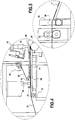
- the fingers are carried by an arm 30 ( figure 7 ) fixed to the frame of the installation 32 and which passes above and on either side of the lower scrolling sheet and the conveyor belt.
- the lower sheet is mechanically deformed downwards to hollow out, by elastic deformation, furrows which will subsequently form, when the dry compress is manufactured, the powder retention compartments.
- a powder deposition device 34 comprising a metering support 36 mounted at the outlet of a hopper for feeding powder of absorbent particles 38.
- the metering units are spaced relative to each other so that each metering unit 36 is located above the furrows previously formed in the moving sheet.
- the distributor is of the rotary cylinder type at the surface of which are hollowed out cells for driving the powder directed towards the metering units.
- an excess particle suction hood here not shown, is provided to the left of the rotary distributor cylinder.
- each metering unit 36 Periodically, at the rate at which the compresses to be distinguished from one another succeed one another, each metering unit 36 delivers a predetermined dose of absorbent powder 6 in each groove 29.
- the powder is thus deposited, in successive doses, over only part of the length to allow subsequent welding of the grooves to be made in the transverse direction with respect to the direction of travel and the cutting of the compresses. successive between two transverse weld lines.
- the strip of textile material also permeable to water, which forms the upper sheet 22 in the compress is pressed onto the lower sheet 20, trapping between the sheets the powder previously deposited. Due to the arrangement of the powder in the furrows, the powder is not dispersed when plating the top sheet to the bottom sheet.
- the top sheet is unwound from a second roll 23.
- the second roll could be fixed to the frame of the installation near the area where the two sheets overlap.
- the path of the top sheet is then longer in that the sheet must pass over the dosers 36 so that it does not obstruct the powder supply for distribution between the top sheet and the bottom sheet of the compress. .
- the upper sheet is pressed against the lower sheet, and against the powder deposited on this lower sheet, at the level of a plating roll 40 on which the upper sheet is driven and under which the lower sheet passes.
- the lower sheet 20 rests on the conveyor belt 24 which begins upstream of the preforming fingers and which goes to the first welding station 42 of the two sheets one on the other.
- the conveyor belt is adapted to pass under a welding table 41 at which the sheets and the powder inside will be compressed between the belt and said table.
- Return rollers are provided for the path of the upper sheet as well as for the path of the lower sheet.
- the roller 43 is arranged before the plating roll 40 on the path of the upper sheet, which is mounted in a floating axis not parallel to the axis of rotation of the other rollers to facilitate the transverse adjustment of the upper sheet so that the edges of the latter correspond with the edges of the lower sheet,
- the assembly thus formed by the lower and upper sheets between which the powder rests, passes over the conveyor belt and under the welding table which is directly mounted on the frame after the plating roller and which allows it to be held in position. of the assembly while flattening it, which ensures the dispersion of the powder inside the grooves.
- the welding table has projecting studs 44, arranged on the path of the sheets at the level of the intervals between the grooves, where the powder is not present. These studs in series in the longitudinal direction maintain in the intervals between the furrows the upper sheet firmly pressed against the lower sheet which is pressed on the conveyor belt.
- the assembly On leaving the welding table, the assembly leaves the conveyor belt and passes over a first ultrasonic welding station 42 which comprises an anvil 46 and a set of sonotrodes 48 ( figures 4 and 6 ).
- the anvil is formed by a roller on which seven treads 47 are arranged in relief and which correspond to the five intervals between the grooves and to the two lateral end edges.
- There are thus seven sonotrodes which come to apply a pressure on the sheets at the level of each of the treads and to restore the energy caused by the ultrasound to spot weld the upper sheet to the lower sheet longitudinally, in the direction of travel of the bandaged.
- the first welding station further comprises cooling air blowing nozzles 50, as illustrated in the figures and particularly visible in the figures. figures 4 and 6 .
- the running strip is then made of two sheets of permeable non-woven material enclosing between them the islands of powder of super-absorbent particles which are spread out and retained in the cavities formed by the grooves and which are now isolated by longitudinal weld lines 52
- the transverse lines 54 are then welded in each groove across the scroll ensuring the separation of the successive sections of film and powder intended to constitute successive dry compresses,
- a second ultrasonic welding station 56 which here comprises a sonotrode and an anvil formed, in a spiral on a rotating cylinder.
- the anvil has a relief over a width corresponding to twice a transverse end line of a compress, it being understood that this weld is carried out before cutting.
- There is a sonotrode which applies pressure to the sheets at the level of the tread and restores the energy caused by the ultrasound to weld the upper sheet to the lower sheet transversely.
- the second welding station has an anvil cylinder cooling device.
- this device may include a curved baffle onto which the jets of the cooling air blowing nozzles are directed. This prevents these jets from directly reaching the locations containing the powder particles and from being able to move them towards the areas reserved for welding.
- the cutting device comprises two rollers between which pass the successive dry compresses.
- One of the rollers has a cutting blade 60 arranged in a helix and which at each passage facing the opposite roller cuts the assembly transversely.
- the speed of revolution of this cutting blade roller as well as its diameter are such that the blade cuts transversely the assembly while moving in the middle of each transverse end weld, thus separating from each other successively each dry compress manufactured.
- the cut dry compress 1 is placed at the outlet of the manufacturing unit 8 on the conveyor belt 16.
- the installation comprises a pneumatic gripping transfer device 62 which is controlled to automatically pick up a group of dry compresses placed on the conveyor belt, transfer them from said compresses manufacturing unit to the conditioning unit and release them by deactivation suction cups to deposit them in their respective locations, that is to say as will be described below on the lower envelope sheet of the article which has already been preformed.
- a pneumatic gripping transfer device 62 which is controlled to automatically pick up a group of dry compresses placed on the conveyor belt, transfer them from said compresses manufacturing unit to the conditioning unit and release them by deactivation suction cups to deposit them in their respective locations, that is to say as will be described below on the lower envelope sheet of the article which has already been preformed.
- Each gripper 18 of the transfer device 62 comprises a suction cup and means for connecting this suction cup to a vacuum circuit.
- Each of the grippers is thus capable respectively of gripping a dry compress by suction by means of its suction cup, and of releasing a dry compress gripped by blowing air into said suction cup.
- Grippers are grouped into modules together forming a gripping matrix.
- the suction cups of the various grippers form a two-dimensional mesh with a surface area of predetermined area.
- the transfer device 62 is suitable for simultaneously gripping several compresses on the conveyor belt, here two in order to be able to come and place them at the same time. in trays formed side by side in the packaging unit. It is understood that the essential according to the invention for this transfer operation is that the dry compresses and the associated water sachets are positioned in the corresponding tray before the top sheet is folded down to enclose them under vacuum packaging.
- the transfer device can be associated with a control station which ensures by visiometry that the controlled dry compress, before filling the sterile article, does indeed contain absorbent powder.
- the installation according to the invention which is described here further comprises a unit for vacuum packaging finished articles 14 in which the operation is also carried out by rolling, from two rolls from which are unwound films of impermeable plastic material, which will be thermally bonded to each other to form a packaging envelope after a compress and a bag of water have been placed between the two films, in a tray preformed in one of the films, and after the vacuum has been made there.
- a first roll 64 of a waterproof and airtight film unwinds and the film is adapted to form the bottom sheet of the article 66, which continuously feeds the vacuum packaging unit.
- the lower sheet passes through an oven 68, in which thermal forming of the areas of the sheet is carried out, thereby forming receiving trays 70.
- an oven 68 in which thermal forming of the areas of the sheet is carried out, thereby forming receiving trays 70.
- two trays are formed side by side on the same width of the sheet.
- the lower sheet is kept stretched between two series of grippers which grip the edges and which are carried by two side chains for driving the sheet, so that no countermould is provided. for preforming.
- the drive side chains provide jerky scrolling of the bottom sheet and thereafter, as this will be described below, that of the top sheet.
- This jerky drive distinct from the continuous scrolling in the dry compresses manufacturing unit, here makes it possible to ensure a necessary pause time so that the lower sheet remains sufficient time in the oven to carry out the desired shaping and then, like that. will be described, the vacuum and thermal welding,
- the trays 70 are filled with a dry compress 1 and a sachet of water 10. It is observed here that the arrival of the compresses and of the water sachets on the conditioning unit 14 takes place on the side and not at the start of the shift. A dry compress and a sachet of water must be housed in a tray already preformed in the lower sheet of the packaging envelope, before being covered by the upper sheet of this envelope. It will then be understood that the thickness of the compresses at the outlet of the manufacturing unit is determined so that a dry compress and the associated bag of water are entirely contained in the volume of the tray.
- the dry compresses are transferred by the grippers 18.
- the water sachets can be transferred as well, unless they are carried manually.
- the arrangement of the water bag relative to the compress in the article may be different from that shown in the pictures. figures 1 and 2 , in which the water sachet is initially deposited against the lower sheet of the packaging envelope (as shown by arrow A of the figure 1 ), the compress being placed on the bag of water so that the latter rests between the compress and the lower sheet of the envelope.
- the compress is placed above the bag of water (arrow B, figure 1 ) and is then held in this position by the top sheet flap (arrow C, figure 1 ).
- the water sachet is initially placed in the center of the tray and the compress is placed over it without modifying this central position of the water sachet. It can advantageously be provided an adhesive means on the bag of water to make it keep this central position which is preferred for reasons of homogeneous water flow in the pad.
- a top sheet 74 is placed on top of it. of the lower leaf.
- a roll 76 is fixed above the thermal welding station and is unwound continuously.
- the topsheet is also stretched between the two sets of grippers which grip edges and which are carried by two side web drive chains.
- the tension between the same series of clamps allows the transverse adjustment of the upper sheet relative to the lower sheet and the maintenance of tension of these sheets necessary for the welding and the vacuuming without there being any retraction.
- the welding and the evacuation in the station 72 are carried out in three stages, first of all by closing the edges around each tray by welding the sheets to each other with the exception of the rear edge of said tray. , then by successively evacuating in the direction of travel of the assembly upstream of the transverse weld of the rear edge of each tray, before finally proceeding to complete the closing of each tray by welding this rear edge left open initially for vacuuming.
- This thermal welding operation is therefore carried out on all the areas surrounding the receiving trays for the compresses.
- the thermal sealer thus secures the attachment of the top sheet against the bottom sheet, effectively enclosing the pad and the water bag inside in a sealed vacuum environment.
- the materials of the sheets of the same packaging envelope are of a different nature depending on whether it is the upper sheet or the lower sheet which must be receptive to the thermal forming operation of the trays.
- the bottom sheet should be formed of a thermosetting material to permanently assume the tray shape while the top sheet may be of other plastic material.
- both sheets are waterproof, mainly to retain water inside when the water bag is punctured. They are also airtight so that the assembly remains under vacuum and preserves its sterile state in the event of prior treatment, sheltered from any intrusion of bacteria from the ambient air.
- the two sheets are thermally welded on their facing faces to ensure this sealing and this vacuum.
- a seam line preferably the trailing edge weld made after the vacuum has been drawn, is a low resistance line to allow peelability and thereby manually ensure opening of the finished medical device for use. of the compress soaked in water and cooled that it contains. This peelability is facilitated by making at least one of the two sheets of the envelope with an outer layer of weakly adhesive material.
- the drive side chains provide jerky scrolling of the two sheets which ensures a necessary pause time so that the assembly remains a sufficient time in the welding station and evacuating so that the vacuum is carried out and that the sheets are welded to each other.
- the assembly is taken up on the edges of the sheets welded to one another by clamps provided on conveyor chains as before, ensuring the same jerky movement.
- the assembly then passes into a cutting station 78 in which the cutting of the individually wrapped compresses is carried out with a punch, with a longitudinal and transverse cut to separate the articles from one another. We observe that a cut is also made on the sides.
- the lateral ends of the films 80 are then wound on reels 82 fixed at the outlet of the cutting station and provided on either side of the belt, and which carry out the drive of the sheets through the entire packaging unit. by winding the edges.
- the wrapped articles When cutting, the wrapped articles fall out. They can fall directly into a bin or onto an output belt 84 which takes shape in the cutting station.
- the water sachets placed in the trays with the dry compresses can be brought manually or be transferred by a transfer device equivalent to that described above from a machine for manufacturing water sachets which may include advantageously the manufacturing installation according to the invention.
- the machine is the same type as those used for all kinds of liquid cartons.
- a plastic sheet is folded so that the two side edges overlap to form a tube closed on itself by welding along a generatrix.
- This lateral weld is carried out so as to subsequently form a frangible zone adapted to yield when the user presses strongly on the article to soak the dry compress with water in order to activate its cooling effect on a wound.
- the tube is placed in thermal welding jaws transversely of the axis of the tube and a transverse weld of the tube is made which will form the lower weld line of the bag.
- Pressurized water is then made to flow in successive doses in the center of the tube so that the tube fills with water, while checking the level of filling by a probe,
- the water is filtered through sieves at 0.2 microns and it is additionally added with chlorine for an antibacterial treatment avoiding its contamination in the pipes which convey it.
- an upper transverse seal is produced, thus forming a bag which encloses the water.
- the bag thus formed is cut and released from the installation to be subsequently placed in the packaging envelope.
- the top seal line of the previous bag then forms the bottom seal line of the next bag and the filling, sealing and cutting process continues cyclically.
- the lateral sealing is carried out on the one hand to ensure the watertight closure of the bag throughout the manufacturing operations and to resist handling of the bags and on the other hand to yield, in the finished product, as soon as the 'we press flat on the article and therefore on the bag of water, so that the water comes to soak the compress.
- the sachet of water is placed first in the bottom of the tray before the dry compress, as described above, and this tray itself comprises a preformed bowl at the bottom, which extends down the center and is shaped like a bag of water.
- the bag is slid into the cuvette and is locked there in translation in two directions.
- Positioning the dry compress in the tray permanently encloses the bag which can no longer move
- the bowl being placed in the center of the tray the water bag takes a central position relative to the dry compress, which will not move when the top sheet is folded over the bottom sheet of the envelope.
- the packaging envelope is sufficiently large to contain the dry compress and the bag of water laid flat one on top of the other.
- the compress which is placed first in the bottom of the tray, and the bag of water is placed on the compress, in its center. It is then possible to plan to turn the dry compress upside down when it is transferred by the grippers, and to place the dry compress first in the packaging envelope with the lower sheet facing upwards, ready to be used. receive the bag of water.
- the water sachet is directly in contact with the lower sheet and the water which is expelled from the sachet is more quickly in contact with the super absorbent particles.
- the water sachet is held in a central position by the immediate flap of the flat top sheet which secures the sachet relative to the compress.
- the result of this manufacturing process is a compress that is easy to use and meets the demanding criteria of sterility in hospital environments.
- the article comprises, inside a vacuum packaging envelope formed of two sheets 66, 74 welded to one another, a bag 10 filled with water and sealed against water by a wall. comprising a frangible zone 12 as well as the compress 2 which contains particles of polymer in the dry state 6.
- the packaging envelope is made of a material impervious to water and to air such as to hold the bag of water and the compress to the air. vacuum sterile state.
- the sheets forming the wall of the packaging envelope consist for example of a mixture of polyamide and polyethylene.
- a material has the particularity of being compatible with a sterilization treatment by gamma rays. This means that on the one hand, this material is not degraded during such a sterilization treatment, and that on the other hand it allows gamma rays to pass, thus making it possible to achieve effective sterilization of the elements contained in the packaging envelope.
- the walls of the packaging envelope are transparent, so that we can see through them. This makes it possible to be able to monitor the state of the elements contained in the packaging envelope.
- the compress comprises two sheets welded to one another and between which are arranged particles of a polymer with a high water absorption capacity, initially in the dry state.
- the sheets which enclose the particles are made of a non-woven material permeable to water and air.
- This material is compatible with a sterilization treatment by gamma rays, which implies that on the one hand it resists such treatment, and on the other hand it does not block the passage of gamma rays, thus allowing the sterilization of the particles which are inside the compress.
- the sheet material exhibits good compressive strength, that which is exerted by the ambient air on the vacuum article before the activation of the polymer, and that also which is exerted on the walls of the compress by the polymer particles when the latter swell by absorption of water, expand greatly and rapidly.
- the sheets are better in water permeability to activate the cooling effect polymer if they are made of a non-water-absorbent material.
- yarns of artificial resin such as polyester resin, are preferably used.
- the compress On its edges formed by the opposite ends of each wall, the compress is closed by weld lines in order to prevent particles from escaping.
- the weld lines are relatively wide, in particular of a width of between 3 and 7 mm, which increases their resistance to the force exerted on them by the polymer particles which expand when they absorb water.
- the sheets forming the compress are adherent to one another along different longitudinal lines produced by ultrasonic welding, so as to form a plurality of elongated compartments in which the polymer particles are homogeneously distributed.
- the compress has six compartments isolated from each other with respect to the polymer particles.
- the weld lines obtained are also mechanically resistant to the forces exerted on them by the polymer particles swelling by water absorption.
- the absorbent polymer particles used are in themselves known, as they are chosen here to be devoid of toxicity. These polymer particles, which are at the origin of the cooling effect produced by the compress, when the particles which have been activated beforehand, that is to say swollen by the water which they have absorbed, after possibly having undergone a stay in a cold environment, generate cold by desorption and vaporization of the water they had absorbed.
- the water sachet is hermetically closed, in particular by welding.
- the welds made are strong enough not to break when the article is handled for transport.
- at least one of the welds is designed in such a way that it can give way, at least in part, under the effect of a pressure which would be exerted by the user on the outer surface of the bag of water, through the packaging envelope.
- a strong enough pressure exerted with the hand on the compress makes it possible to break the frangible zone of the bag and to release the water to come inside the packaging envelope, impregnate the polymer retained in the envelope of the compress itself.
- the water sachet contains only the correct amount of water, as much as possible without air bubbles.
- This quantity is determined as a function of the quantity of polymer particles included in the different retention compartments of the polymer powder and of the water absorption capacity of the particles, so that it is fully absorbed during opening the bag of water. It is doubly advantageous for the quantity of polymer to be in excess with respect to the water, on the one hand to prevent liquid water from remaining in the packaging envelope when it is opened and on the other hand to that the particles remain in demand for water in the vicinity of the textile walls of the compress.
Landscapes
- Health & Medical Sciences (AREA)
- Engineering & Computer Science (AREA)
- Animal Behavior & Ethology (AREA)
- General Health & Medical Sciences (AREA)
- Biomedical Technology (AREA)
- Heart & Thoracic Surgery (AREA)
- Vascular Medicine (AREA)
- Life Sciences & Earth Sciences (AREA)
- Physics & Mathematics (AREA)
- Thermal Sciences (AREA)
- Public Health (AREA)
- Veterinary Medicine (AREA)
- Mechanical Engineering (AREA)
- Chemical & Material Sciences (AREA)
- Dispersion Chemistry (AREA)
- Containers And Plastic Fillers For Packaging (AREA)
- Packages (AREA)
- Auxiliary Devices For And Details Of Packaging Control (AREA)
Description
La présente invention concerne la fabrication industrielle d'articles de soin à base de compresses à effet refroidissant par gonflement à l'eau.The present invention relates to the industrial manufacture of care articles based on compresses with a cooling effect by swelling in water.
Dans le domaine des articles à usage médical notamment, on connaît de telles compresses, dont le fonctionnement est dû à l'activité cryogénique dont sont capables des particules de polymères absorbants ayant retenu de grandes quantités d'eau. On parle de polymères actifs en réfrigération par absorption d'eau, ou de polymères activés par gonflement à l'eau, sachant que l'effet cryogénique se produit essentiellement par vaporisation de l'eau lors de sa désorption hors des particules absorbantes.In the field of articles for medical use in particular, such compresses are known, the operation of which is due to the cryogenic activity of which the particles of absorbent polymers which have retained large quantities of water are capable. We are talking about polymers active in refrigeration by absorption of water, or polymers activated by swelling with water, knowing that the cryogenic effect occurs essentially by vaporization of water during its desorption from the absorbent particles.
On connaît de l'art antérieur, et notamment de la demande de brevet
La présente invention décrit dans les revendications indépendantes 1,3 et 12 un procédé de fabrication d'article à compresses à effet refroidissant, une installation de fabrication de ces articles et l'article lui-même respectivement. Des modes de réalisation préférés du procédé, de l'installation et de l'article sont décrits dans les revendications dépendantes. La présente invention vise à permettre la fabrication en série d'articles ainsi constitués, dans des conditions compatibles avec une production à l'échelle industrielle, notamment en termes de rapidité, de coût et de fiabilité. Elle se propose aussi par là d'apporter des perfectionnement à la réalisation des articles eux-mêmes en améliorant leurs propriétés, notamment pour ce qui concerne la qualité des compresses dans leur effet réfrigérant et la sécurité d'emploi.The present invention describes in
A titre principal, les caractéristiques propres à la présente invention concerne la fabrication des compresses elles-mêmes, sous la forme de polymère absorbant encore à l'état sec retenu dans une paroi perméables à l'eau. D'autres caractéristiques viennent avantageusement la compléter concernant leur assemblage chacune avec un sachet d'eau fracturable dans une enveloppe de conditionnement sous vide. On retiendra en outre que parmi les caractéristiques propres à la présente invention, il en est qui ont intérêt pour le procédé et l'installation de fabrication des articles, mais aussi pour les propriétés des articles considérés pour eux-mêmes. Tel est le cas notamment des particularités touchant à la nature des feuilles enfermant le polymère dans la compresse ou à celle des parois de l'enveloppe de conditionnement stérile de l'article fini avec la disposition relative entre sachet d'eau et compresse dans cette enveloppe.Mainly, the characteristics specific to the present invention relate to the manufacture of the compresses themselves, in the form of an absorbent polymer still in the dry state retained in a wall permeable to water. Other characteristics advantageously supplement it concerning their assembly each with a sachet of water which can be fractured in a vacuum packaging envelope. It will also be remembered that among the characteristics specific to the present invention, there are some which are of interest for the process and the installation for manufacturing the articles, but also for the properties of the articles considered for themselves. This is the case in particular for the particularities relating to the nature of the sheets enclosing the polymer in the compress or to that of the walls of the sterile packaging envelope of the finished article with the relative arrangement between the bag of water and the compress in this envelope. .
Que ce soit en termes de procédé ou en termes d'installation, l'invention prévoit essentiellement de procéder par laminage entre deux feuilles en une matière de rétention des particules de polymère absorbant mais perméable à l'eau pour fabriquer en série des compresses dites sèches contenant le polymère à l'état sec réparti dans plusieurs compartiments pour former ensemble une compresse plate.Whether in terms of method or in terms of installation, the invention essentially provides for proceeding by rolling between two sheets of a material for retaining the particles of absorbent polymer but permeable to water in order to mass produce so-called dry compresses. containing the polymer in the dry state distributed in several compartments to form together a flat compress.
Pour l'une des feuilles, celle de préférence qui est utilisée en feuille inférieure en cours de fabrication des compresses, on choisit avantageusement une matière à déformation thermique élastiquement réversible. Alors que pour l'autre feuille, de préférence celle passant en feuille supérieure lors des opérations de fabrication, on a intérêt à privilégier la résistance mécanique, en particulier en résistance à l'allongement sous traction pendant le laminage, quitte à perdre sur la perméabilité de la paroi correspondante dans la compresse sèche obtenue. C'est alors la face de la compresse occupée par la feuille élastiquement déformable à chaud et plus perméable que l'on choisira pour se placer au mieux contre le sachet d'eau dans l'article fini.For one of the sheets, the one which is preferably used as the lower sheet during the manufacture of the compresses, an elastically reversible thermal deformation material is advantageously chosen. While for the other sheet, preferably the one passing into the upper sheet during manufacturing operations, it is advantageous to favor the mechanical strength, in particular in resistance to elongation under traction during lamination, even if it means losing the permeability. of the corresponding wall in the dry compress obtained. It is then the face of the compress occupied by the elastically hot-deformable and more permeable sheet that will be chosen in order to best place itself against the bag of water in the finished article.
Sous ses formes de mise en œuvre préférées, l'invention prévoit aussi de faire appel aux techniques de laminage dans une unité de conditionnement réalisant la fabrication en série des articles finis pour commercialisation, où chaque compresse sèche est enfermée avec son sachet d'eau dans une enveloppe sous vide. Ladite enveloppe est alors constituée à partir de deux feuilles en défilement continu qui sont en une matière étanche à l'eau comme à l'air qui sont soudées ensemble autour de chaque ensemble sachet d'eau et compresse sèche l'un sur l'autre. Dans les modes de mise en œuvre préférés de l'invention, la feuille défilant en feuille inférieure dans le processus de fabrication est à déformation plastique à chaud, de sorte que l'on y ménage des cuvettes de réception des sachets d'eau supportant chacun la compresse associée. Alors que pour la feuille servant de feuille supérieure de laminage on a intérêt à privilégier les propriétés mécaniques de résistance à toute déformation. Non seulement on favorise ainsi de bonnes conditions de mise en œuvre du procédé de fabrication dans l'unité de conditionnement, mais en outre on obtient un résultat avantageux pour les conditions d'utilisation de l'article fini. En effet, il sera facile à l'utilisateur l'assurer la rupture du sachet et la libération de l'eau en agissant sur la paroi de l'enveloppe relativement rigide provenant de cette feuille supérieur, en particulier quand elle se trouve alors mitoyenne avec le sachet d'eau.In its preferred forms of implementation, the invention also provides for the use of rolling techniques in a packaging unit carrying out the mass production of finished articles for marketing, where each dry compress is enclosed with its bag of water in a vacuum envelope. Said casing is then formed from two continuously moving sheets which are of a waterproof as well as airtight material which are welded together around each water bag assembly and dry compress one on top of the other. . In the preferred embodiments of the invention, the sheet moving into the lower sheet in the manufacturing process is hot plastic deformation, so that there are provided receiving basins for each of the water bags. the associated compress. While for the sheet serving as the top laminating sheet, it is advantageous to favor the mechanical properties of resistance to any deformation. This not only promotes good conditions for implementing the manufacturing process in the packaging unit, but also an advantageous result is obtained for the conditions of use of the finished article. Indeed, it will be easy for the user to ensure the breaking of the bag and the release of the water by acting on the wall of the relatively rigid casing coming from this top sheet, in particular when it is then located adjacent to it. the bag of water.
On s'intéressera maintenant à préciser la constitution d'une installation suivant l'invention ainsi que le procédé correspondant en se référant à des modes de réalisation préférés de l'invention, qui cependant ne sont pas limitatifs.We will now focus on specifying the constitution of an installation according to the invention as well as the corresponding method with reference to preferred embodiments of the invention, which however are not limiting.
L'installation comporte principalement une unité de fabrication de compresses sèches adaptées à absorber de l'eau pour produire l'effet refroidissant, dans laquelle on fait passer sous une trémie d'alimentation en poudre de particules absorbantes une feuille inférieure de matière perméable à l'eau (avantageusement une matière textile) qui est déroulée de manière continue le long de l'unité et qui est entraînée à plat par laminage vers la sortie de l'unité et on dépose des doses successives de ladite poudre dans des sillons formés longitudinalement dans ladite feuille inférieure par déformation élastiquement réversible de celle-ci. Puis on recouvre l'ensemble d'une feuille supérieure (avantageusement également en matière textile et perméable à l'eau) qui est déroulée de manière continue et qui est entraînée à plat par laminage simultanément avec la bande de feuille inférieure vers la sortie de l'unité.The installation mainly comprises a unit for manufacturing dry compresses suitable for absorbing water to produce the cooling effect, in which a lower sheet of material permeable to water is passed under a hopper for feeding powder of absorbent particles. water (advantageously a textile material) which is unwound continuously along the unit and which is driven flat by rolling towards the outlet of the unit and successive doses of said powder are deposited in grooves formed longitudinally in said lower sheet by elastically reversible deformation thereof. Then the whole is covered with a top sheet (advantageously also of textile material and permeable to water) which is unwound continuously and which is driven flat by rolling simultaneously with the strip of lower sheet towards the outlet of the film. 'unity.
Ainsi on assure au cours du défilement la bonne répartition du polymère sur toute la surface de chaque compresse, d'une part en direction transversale au défilement par la présence de différents sillons côte à côte, d'autre part dans la direction longitudinale du défilement par le fait que chaque dose de poudre délivrée se trouve automatiquement étalée dans ce sens, chacune sur une étendue correspondant à une compresse.Thus, during the travel, the good distribution of the polymer over the entire surface of each compress is ensured, on the one hand in the direction transverse to the travel by the presence of different grooves side by side, on the other hand in the longitudinal direction of the travel by the fact that each dose of powder delivered is automatically spread in this direction, each over an area corresponding to a compress.
Selon une autre caractéristique de l'invention, on isole transversalement les uns des autres les sillons adjacents remplis de poudre en soudant ensemble la feuille supérieure et la feuille inférieure le long des intervalles entre sillons adjacents et on ferme dans chaque sillon des compartiments successifs contenant chacun une dose de poudre en soudant l'une avec l'autre les feuilles suivant des lignes de soudure transversales en travers de l'ensemble en défilement.According to another characteristic of the invention, the adjacent grooves filled with powder are isolated transversely from each other by welding the upper sheet and the lower sheet together along the intervals between adjacent grooves and successive compartments each containing each groove are closed. a dose of powder by welding the sheets together along transverse weld lines across the moving assembly.
Ainsi, tout de suite après le dépôt de poudre, on délimite des compartiments pour s'assurer que la poudre sera correctement répartie uniformément sur toute l'étendue de chaque compresse. On notera ici, que dans la compresse finie, les sillons sont estompés, du fait qu'en fin de l'unité de fabrication de compresses sèches, la feuille inférieure tend à reprendre élastiquement sa forme plane d'origine.Thus, immediately after the powder has been deposited, compartments are delimited to ensure that the powder will be correctly distributed uniformly over the entire extent of each compress. It will be noted here that in the finished compress, the furrows are blurred, because at the end of the dry compress manufacturing unit, the lower sheet tends to elastically resume its original flat shape.
Les deux feuilles laminées constituent après soudage l'enveloppe de rétention des particules absorbantes. Elles sont donc réalisées perméables à l'eau. On utilise avantageusement un matériau textile non tissé. En pratique on s'attache à ce que l'une des deux feuilles soit de matière perméable à l'eau, alors que l'autre peut être en non tissé moins lâche, et donc plus résistante. Dans ce cas, on utilise de préférence la feuille plus perméable à l'eau comme feuille inférieure, car sa constitution lui confère alors une souplesse qui est favorable pour la mise en forme du sillon de réception de la poudre.After welding, the two laminated sheets constitute the envelope for retaining the absorbent particles. They are therefore made permeable to water. Advantageously, a non-woven textile material is used. In practice, it is essential that one of the two sheets is made of a material permeable to water, while the other can be made of a less loose nonwoven, and therefore more resistant. In this case, the more water-permeable sheet is preferably used as lower sheet, because its constitution then gives it flexibility which is favorable for the shaping of the furrow for receiving the powder.
Selon une caractéristique de l'invention, les sillons dans lesquels la poudre va être déposée sont formés élastiquement dans la feuille inférieure par des doigts distincts les uns des autres disposés en ligne en travers du défilement de la feuille inférieure de la compresse, lesdits doigts chauffant la feuille inférieure tendue et la déformant mécaniquement, de façon élastique. On réalise ainsi une déformation temporaire de la feuille jusqu'à ce qu'après avoir reçu la poudre elle tendre à revenir à sa forme d'origine. On prévoit un doigt pour chaque sillon souhaité,According to one characteristic of the invention, the grooves in which the powder will be deposited are formed elastically in the lower sheet by fingers distinct from each other arranged in line across the movement of the lower sheet of the compress, said heating fingers. the lower sheet stretched and deforming it mechanically, elastically. A temporary deformation of the sheet is thus achieved until after having received the powder it tends to return to its original shape. One finger is provided for each desired groove,
Selon une caractéristique de l'invention, l'étape de dépôt de poudre est réalisée par un ensemble de doseurs espacés l'un par rapport à l'autre pour que chaque doseur soit situé au-dessus de l'un des sillons de la feuille inférieure en défilement. Cette position des doseurs permet un dépôt de poudre maîtrisable et répétable, pour s'assurer que la même quantité de poudre sera présente dans chaque compresse et dans chaque sillon.According to one characteristic of the invention, the powder deposition step is carried out by a set of metering units spaced relative to each other so that each metering unit is located above one of the furrows of the sheet. lower scrolling. This position of the dosers allows a controllable and repeatable powder deposition, to ensure that the same quantity of powder will be present in each compress and in each groove.
Selon une caractéristique de l'invention, on prévoit lors des opérations de soudure des moyens de refroidissement à buses de soufflage d'air et on s'assure que les moyens de refroidissement soient munis d'un déflecteur pour protéger les sillons remplis de poudre des jets d'air soufflé, et pour conserver ainsi la bonne répartition de la poudre.According to one characteristic of the invention, during the welding operations, cooling means with air blowing nozzles are provided and it is ensured that the cooling means are provided with a deflector to protect the furrows filled with powder from blown air jets, and thus maintain the good distribution of the powder.
En outre, l'installation selon l'invention comporte une unité de conditionnement faisant suite à l'unité de fabrication de compresse sèche.In addition, the installation according to the invention comprises a conditioning unit following on from the dry compress manufacturing unit.
Dans cette unité, on réalise par formage thermique des barquettes individuelles de réception de compresses sèches dans une première feuille en matière étanche à l'eau et à l'air et qui est entraînée à plat vers la sortie de l'unité pour y déposer l'un par dessus l'autre un sachet d'eau réalisé par ailleurs et une compresse sèche fabriquée précédemment.In this unit, individual trays for receiving dry compresses are produced by thermal forming in a first sheet of waterproof material and airtight and which is driven flat towards the outlet of the unit to deposit the material therein. 'one above the other a sachet of water produced elsewhere and a dry compress produced previously.
On recouvre l'ensemble par une deuxième feuille en matière étanche à l'eau et à l'air qui est entraînée à plat vers la sortie de l'unité simultanément à la feuille inférieure et on ferme les bords autour de chaque barquette par soudure des feuilles l'une sur l'autre en faisant préalablement le vide entre les feuilles.The assembly is covered with a second sheet of waterproof and airtight material which is drawn flat towards the outlet of the unit simultaneously with the lower sheet and the edges are closed around each tray by welding leaves one on top of the other by making a gap between the leaves beforehand.
Le fait que les deux feuilles .formant parois de l'enveloppe de conditionnement soient étanches à l'eau permet d'assurer que l'eau qui va sortir du sachet va être utilisée entièrement pour imbiber la compresse. Le fait que ces feuilles soient étanches à l'air et que le vide soit fait entre les feuilles avant le collage assurent un environnement isolé de l'humidité de l'air jusqu'à ce que l'enveloppe soit ouverte pour récupérer la compresse imbibée. Dans le cas d'une fabrication réalisée dans des conditions stériles, l'étanchéité des feuilles et la mise sous vide permettent d'assurer la conservation des conditions stériles jusqu'à l'ouverture de l'enveloppe.The fact that the two sheets forming the walls of the packaging envelope are watertight makes it possible to ensure that the water which will come out of the sachet will be used entirely to soak the compress. The fact that these sheets are airtight and that a vacuum is made between the sheets before gluing ensures an environment isolated from the humidity of the air until the envelope is opened to collect the soaked compress . In the case of manufacture carried out under sterile conditions, the sealing of the sheets and the placing under vacuum make it possible to ensure that sterile conditions are preserved until the envelope is opened.
Selon une caractéristique de l'invention, la réalisation par formage thermique des barquettes est dimensionnée pour qu'une compresse sèche et un sachet d'eau associé soient entièrement contenus dans le volume de ladite barquette.According to one characteristic of the invention, the production by thermal forming of the trays is dimensioned so that a dry compress and an associated bag of water are entirely contained in the volume of said tray.
On s'assure alors que la compresse et le sachet ne bougent plus dès lors qu'ils sont mis en place dans la barquette, et on protège le sachet d'eau à l'intérieur de cette barquette pour éviter qu'il ne rompe sans intention volontaire de l'utilisateur.We then make sure that the compress and the bag do not move when they are placed in the tray, and we protect the water bag inside this tray to prevent it from breaking without voluntary intention of the user.
On peut prévoir des moyens de maintien en position du sachet d'eau pour s'assurer de garder une position centrale du sachet par rapport à la compresse dans l'enveloppe de conditionnement sous vide.Means can be provided for holding the bag of water in position to ensure that the bag is in a central position relative to the compress in the vacuum packaging envelope.
Les sachets d'eau peuvent également être réalisés dans l'installation, dans une unité avantageusement parallèle à l'unité de fabrication de compresses sèches.The water sachets can also be produced in the installation, in a unit advantageously parallel to the dry compresses manufacturing unit.
Dans cette unité de fabrication de sachets d'eau, qui est disposée en amont de l'unité de conditionnement, on amène et l'on soude l'un contre l'autre les deux bords latéraux d'une feuille en matière plastique pour former un tube fermé sur lui-même par soudure le long d'une génératrice, cette soudure latérale des deux bords étant réalisée pour d'une part assurer la fermeture étanche du sachet pendant tout le temps des opérations de fabrication et résister aux manipulations des sachets et d'autre part pour céder, dans le produit fini, dès que l'on appuie à plat sur l'article et donc sur le sachet d'eau, afin que l'eau vienne imbiber la compresse. On définit ainsi une zone frangible adaptée à céder par la suite quand l'utilisateur souhaite imbiber d'eau la compresse sèche pour activer son effet refroidissant sur une plaie.In this water bag manufacturing unit, which is arranged upstream of the packaging unit, the two side edges of a sheet are brought and welded against each other. plastic material to form a tube closed on itself by welding along a generatrix, this lateral welding of the two edges being carried out on the one hand to ensure the tight closure of the bag throughout the manufacturing operations and to resist handling of the sachets and on the other hand to yield, in the finished product, as soon as one presses flat on the article and therefore on the water sachet, so that the water comes to soak the compress. This defines a frangible zone adapted to subsequently give way when the user wishes to soak the dry compress with water in order to activate its cooling effect on a wound.
Une fois cette soudure latérale effectuée, on place le tube ainsi formé dans des mâchoires de soudure thermique en transversal de l'axe du tube et on réalise une soudure transversale de ce tube qui va former la ligne de soudure inférieure du sachet. On fait ensuite s'écouler de l'eau sous pression par doses successives au centre du tube de sorte que le tube se remplisse d'eau. On vérifie le niveau de remplissage d'eau dans le tube par une sonde sensible au niveau de l'eau, puis on réalise la soudure transversale supérieure en formant alors un sachet qui enferme l'eau. On fait attention à ce que la ligne de soudure supérieure soit faite suffisamment en dessous du niveau supérieur de l'eau dans la poche formée entre les feuilles. Ainsi, lors de la soudure, on chasse l'eau en excédent et on s'assure que l'on n'enferme pas des bulles d'air dans le sachet, et d'autre part que la quantité d'eau dans le sachet est bien la quantité requise, nécessaire à la bonne imprégnation de la compresse. Dans une production de sachets d'eau en continu, le sachet ainsi formé est découpé et dégagé de l'installation pour être par la suite disposé dans l'enveloppe de conditionnement. La ligne de soudure supérieure du sachet précédent forme alors la ligne de soudure inférieure du sachet suivant et le processus de remplissage, de soudure et de découpe se poursuit cycliquement.Once this lateral welding has been carried out, the tube thus formed is placed in thermal welding jaws transversely of the axis of the tube and a transverse weld of this tube is made which will form the lower weld line of the bag. Pressurized water is then made to flow in successive doses in the center of the tube so that the tube fills with water. The water filling level in the tube is checked by a probe sensitive to the water level, then the upper transverse weld is made, thus forming a bag which encloses the water. Care is taken that the upper weld line is made sufficiently below the upper water level in the pocket formed between the sheets. Thus, during the welding, we flush out the excess water and we make sure that we do not trap air bubbles in the bag, and on the other hand that the amount of water in the bag is indeed the required quantity, necessary for the good impregnation of the compress. In a continuous water bag production, the bag thus formed is cut and released from the installation to be subsequently placed in the packaging envelope. The top seal line of the previous bag then forms the bottom seal line of the next bag and the filling, sealing and cutting process continues cyclically.
Selon une caractéristique de l'invention, on prévoit le transfert de chaque compresse sèche fabriquée par l'unité de fabrication de compresses sèches et le transfert de chaque sachet d'eau en sortie de l'unité de fabrication de sachets pour transférer un sachet et une compresse dans une barquette préformée dans l'enveloppe de conditionnement au niveau de l'unité de conditionnement.According to one characteristic of the invention, provision is made for the transfer of each dry compress manufactured by the dry compress manufacturing unit and the transfer of each sachet of water at the outlet of the sachet manufacturing unit to transfer a sachet and a compress in a preformed tray in the packaging envelope at the level of the packaging unit.
On prévoit en outre dans cette étape de transfert une opération de contrôle par visiométrie pour s'assurer qu'une dose de poudre absorbante est à l'intérieur de la compresse.In addition, this transfer step provides for a visiometric control operation to ensure that a dose of absorbent powder is inside the pad.
L'invention sera maintenant plus complètement décrite dans le cadre de caractéristiques préférées et de leurs avantages, en faisant référence aux figures dans lesquelles :
- la
figure 1 représente un article à effet refroidissant selon l'invention, dans une vue éclatée où l'on peut voir les deux feuilles formant l'enveloppe de conditionnement, ainsi qu'une compresse et un sachet d'eau qui sont adaptés à être logés entre les deux feuilles dans le produit fini ; - la
figure 2 représente une vue d'ensemble de l'installation de fabrication de l'article représenté à lafigure 1 , avec une unité de fabrication en série des compresses sèches, des moyens de transfert et une unité de conditionnement sous vide de chaque compresse assemblée avec un sachet d'eau ; - la
figure 3 représente une vue partielle de l'unité de fabrication illustrée à lafigure 2 , sans les bobines de déroulement de films de matériau non tissé ; - les
figures 4 et 5 sont des agrandissements des zones IV et V visibles sur lafigure 3 ; - la
figure 6 représente un agrandissement du premier poste de soudage dans l'unité de fabrication de la compresse de lafigure 3 , en fonctionnement à vide sans feuilles ; - la
figure 7 représente un agrandissement du poste de dépôt de poudre absorbante dans l'unité de fabrication de la compresse de lafigure 3 , avec en amont le dispositif de déformation de la feuille inférieure de matériau non tissé et en aval l'arrivée de la feuille supérieure de matériau non tissé.
- the
figure 1 shows an article with a cooling effect according to the invention, in an exploded view where one can see the two sheets forming the packaging envelope, as well as a compress and a bag of water which are adapted to be housed between the two sheets in the finished product; - the
figure 2 represents an overview of the manufacturing facility of the article shown infigure 1 , with a unit for mass production of dry compresses, transfer means and a unit for vacuum packaging each compress assembled with a bag of water; - the
figure 3 represents a partial view of the manufacturing unit illustrated onfigure 2 , without the unwinding reels of films of non-woven material; - the
figures 4 and 5 are enlargements of zones IV and V visible on thefigure 3 ; - the
figure 6 shows an enlargement of the first welding station in the compress manufacturing unit of thefigure 3 , in idle operation without leaves; - the
figure 7 shows an enlargement of the absorbent powder deposition station in the pad manufacturing unit of thefigure 3 , with upstream the device for deformation of the lower sheet of nonwoven material and downstream the arrival of the upper sheet of nonwoven material.
La compresse sèche 1 suivant l'invention est présentée comme partie intégrante d'un article 2, comme cela est illustré pour une meilleure compréhension par une vue éclatée sur la
Un article tel que décrit précédemment est fabriqué de la façon suivante, en se référant particulièrement aux
Une compresse sèche est préparée, sous forme par exemple d'un ensemble de compartiments 4 comportant chacun une quantité adéquate de particules 6 de polymère à l'état sec, dans une unité de fabrication de la compresse 8 décrite ci-après.A dry compress is prepared, for example in the form of a set of
Un sachet d'eau 10 est préparé indépendamment, dans une unité de fabrication de sachet d'eau, en prenant soin de ménager sur sa surface, et notamment au niveau d'une ligne de soudure, une zone frangible 12.A
Une compresse et un sachet d'eau sont alors disposés dans l'unité de conditionnement de l'article 14, dans lequel les feuilles inférieure et supérieure de l'enveloppe de conditionnement sont collées pour enfermer à l'intérieur de l'enveloppe la compresse et le sachet.A compress and a sachet of water are then placed in the packaging unit of
L'article 2 est alors soumis à un traitement de stérilisation par rayons gamma ou par rayons bêta. L'intérieur de l'enveloppe, dont la compresse et l'eau du sachet, est ainsi rendu stérile. Aucun des éléments inclus dans le sachet ne subit de dommage, à l'exception d'une partie des particules dont la réticulation est détruite. Il reste cependant encore suffisamment de particules opérantes pour assurer la délivrance d'un froid efficace.The
On va maintenant décrire plus en détail le procédé de fabrication selon l'invention et l'installation de fabrication permettant la mise en œuvre de ce procédé, en se référant en particulier où l'installation comporte deux unités de laminage en ligne sur le même site, à savoir une unité de fabrication de compresses sèches 8 et une unité de conditionnement des compresses en articles finis 14, avec un tapis convoyeur 16 et des préhenseurs 18 pour réaliser le transfert des compresses sèches d'une unité vers l'autre.The manufacturing method according to the invention and the manufacturing installation allowing the implementation of this method will now be described in more detail, with particular reference to where the installation comprises two rolling units in line on the same site. , namely a unit for manufacturing
Les compresses sèches fabriquées sont destinées à alimenter, associées avec des sachets d'eau, l'unité de conditionnement. Elles sont prises en sortie de l'unité de fabrication des compresses sèches elles-mêmes et elles sont disposées par le côté de l'unité de conditionnement, alors qu'un film a déjà été préformé dans ladite unité de conditionnement pour former des barquettes de réception de ces compresses et sachets.The dry compresses produced are intended to supply, associated with water sachets, the conditioning unit. They are taken at the outlet of the production unit of the dry compresses themselves and they are arranged by the side of the packaging unit, while a film has already been preformed in said packaging unit to form trays of. receipt of these compresses and sachets.
L'unité de fabrication des compresses sèches 8 comporte deux rouleaux pour dévider en continu des feuilles de matière textile perméables à l'eau 20, 22, qui vont être amenées dans cette installation à être soudées l'une à l'autre après que de la poudre absorbante 6 ait été injectée entre ces feuilles, un poste de découpe permettant à la suite des opérations de soudure de scinder les bandes en des compresses sèches,The unit for manufacturing the
A partir d'un premier rouleau de film 21 on déroule en continu le film de matière textile qui est adapté à former la feuille inférieure de la compresse 20. Le film dévidé est repris par des rouleaux de renvoi jusqu'à être amené en regard d'un tapis de convoyage 24 (visible à la
Des doigts de préformage 28 sont disposés au-dessus du tapis, sur le passage de la feuille inférieure. Ils sont en saillie du plan de défilement de la feuille inférieure et ils créent une déformation élastique temporaire de la feuille inférieure en forme de sillons longitudinaux 29. La déformation de la matière textile est réalisée thermiquement par les doigts qui chauffent et creusent des sillons continus le long de la feuille inférieure en défilement. Les doigts sont portés par un bras 30 (
On trouve en aval de ces doigts de préformage, immédiatement après dans le sens de défilement de la bande, un dispositif de dépôt de poudre 34 comportant un support de doseurs 36 montés en sortie d'une trémie d'alimentation en poudre de particules absorbantes 38. Les doseurs sont espacés l'un par rapport à l'autre pour que chaque doseur 36 soit situé au-dessus des sillons formés précédemment dans la feuille en défilement.Downstream of these preforming fingers, immediately after in the direction of travel of the strip, there is a
Le distributeur est du type à cylindre rotatif à la surface duquel sont creusées des alvéoles d'entraînement de la poudre dirigées vers les doseurs. Dans le cas où l'unité de fabrication est à défilement de la gauche vers la droite, comme illustré sur les figures, une hotte d'aspiration des particules en excès, ici non représentée, est prévue à gauche du cylindre rotatif distributeur.The distributor is of the rotary cylinder type at the surface of which are hollowed out cells for driving the powder directed towards the metering units. In the case where the manufacturing unit scrolls from left to right, as illustrated in the figures, an excess particle suction hood, here not shown, is provided to the left of the rotary distributor cylinder.
Périodiquement, au rythme auquel se succèdent les compresses à distinguer les unes des autres, chaque doseur 36 délivre une dose prédéterminée de poudre absorbante 6 dans chaque sillon 29.Periodically, at the rate at which the compresses to be distinguished from one another succeed one another, each
Dans chaque sillon, la poudre est ainsi déposée, par doses successives, sur une partie seulement de la longueur pour permettre de réaliser par la suite les soudures de fermeture des sillons dans le sens transversal par rapport à la direction de défilement et la découpe des compresses successives entre deux lignes de soudure transversales.In each groove, the powder is thus deposited, in successive doses, over only part of the length to allow subsequent welding of the grooves to be made in the transverse direction with respect to the direction of travel and the cutting of the compresses. successive between two transverse weld lines.
On peut observer que l'on a autant de doigts et de doseurs que l'on souhaite de compartiments de rétention de la poudre, pour une compresse donnée. Dans l'exemple représenté, on a six doigts et six doseurs, pour six sillons, comme cela est particulièrement visible sur la
Directement après le dispositif de dépôt, la bande de matière textile, perméable à l'eau elle aussi, qui forme la feuille supérieure 22 dans la compresse est plaquée sur la feuille inférieure 20, en emprisonnant entre les feuilles la poudre déposée préalablement. Du fait de la disposition de la poudre dans les sillons, la poudre n'est pas dispersée lors du placage de la feuille supérieure sur la feuille inférieure.Directly after the deposition device, the strip of textile material, also permeable to water, which forms the
La feuille supérieure est dévidée depuis un deuxième rouleau 23. On comprendra que le deuxième rouleau pourrait être fixé au bâti de l'installation à proximité de la zone de recoupement des deux feuilles. Toutefois, tel qu'illustré sur les figures, il est avantageux que les deux rouleaux soient disposés à proximité, On a ainsi une seule zone de chargement de tissu et, dans le cas où elle est prévue dans l'installation, une unique zone de raboutage dans laquelle les deux feuilles passent sur des tables de raboutage servant à raccorder bout à bout la bande en fin de rouleau avec le début d'une bande d'un rouleau suivant.The top sheet is unwound from a
Le trajet de la feuille supérieure est alors plus long en ce que la feuille doit passer au-dessus des doseurs 36 pour qu'elle n'entrave pas l'alimentation en poudre pour la distribution entre la feuille supérieure et la feuille inférieure de la compresse.The path of the top sheet is then longer in that the sheet must pass over the
La feuille supérieure est plaquée contre la feuille inférieure, et contre la poudre déposée sur cette feuille inférieure, au niveau d'un rouleau de plaquage 40 sur lequel est entraînée la feuille supérieure et sous lequel la feuille inférieure passe. A ce niveau, la feuille inférieure 20 repose sur le tapis de convoyage 24 qui commence en amont des doigts de préformage et qui va jusqu'au premier poste de soudage 42 des deux feuilles l'une sur l'autre. Comme cela sera décrit ci après, le tapis de convoyage est adapté à passer sous une table de soudage 41 au niveau de laquelle les feuilles et la poudre à l'intérieur vont être compressées entre le tapis et ladite table.The upper sheet is pressed against the lower sheet, and against the powder deposited on this lower sheet, at the level of a
On prévoit des rouleaux de renvoi pour le trajet de la feuille supérieure comme pour le trajet de la feuille inférieure, On a ici en particulier le rouleau 43 disposé avant le rouleau de plaquage 40 sur le trajet de la feuille supérieure, qui est monté selon un axe flottant non parallèle à l'axe de rotation des autres rouleaux pour faciliter l'ajustement transversal de la feuille supérieure pour que les bords de celle-ci correspondent avec les bords de la feuille inférieure,Return rollers are provided for the path of the upper sheet as well as for the path of the lower sheet. Here in particular the
L'ensemble, ainsi formé par les feuilles inférieure et supérieure entre lesquelles repose de la poudre, passe sur le tapis de convoyage et sous la table de soudage qui est directement montée sur le bâti après le rouleau de plaquage et qui permet le maintien en position de l'ensemble tout en l'aplatissant, ce qui assure la dispersion de la poudre à l'intérieur des sillons. La table de soudage présente des plots en saillie 44, disposés sur le parcours des feuilles au niveau des intervalles entre les sillons, où la poudre n'est pas présente. Ces plots en série dans le sens longitudinal maintiennent dans les intervalles entre les sillons la feuille supérieure fermement plaquée contre la feuille inférieure qui est pressée sur le tapis de convoyage. Ceci permet de conserver sous cette table de soudage la répartition de la poudre dans les sillons alors que l'ensemble est aplati et que la creusure des sillons s'élargit, et ceci permet ainsi d'éviter à l'arrivée sur les postes de soudage par ultrasons que de la poudre se retrouve dans ces intervalles, qui correspondent aux futures lignes de soudure longitudinales entre les sillons et qui doivent donc rester vierges de poudre pour un soudage optimisé.The assembly, thus formed by the lower and upper sheets between which the powder rests, passes over the conveyor belt and under the welding table which is directly mounted on the frame after the plating roller and which allows it to be held in position. of the assembly while flattening it, which ensures the dispersion of the powder inside the grooves. The welding table has projecting
En sortie de la table de soudage, l'ensemble quitte le tapis convoyeur et il passe sur un premier poste de soudage par ultrasons 42 qui comporte une enclume 46 et un ensemble de sonotrodes 48 (
Le premier poste de soudage comporte en outre des buses de soufflage d'air de refroidissement 50, comme cela est illustré sur les figures et particulièrement visible sur les
La bande en défilement est alors faite des deux feuilles de matériau non tissé perméables enserrant entre elles les îlots de poudre de particules super absorbantes qui sont étalés et retenus dans les cavités formées par les sillons et qui sont isolées désormais par des lignes de soudure longitudinales 52. On réalise alors dans chaque sillon la soudure de lignes transversales 54 en travers du défilement assurant la séparation des sections successives de film et de poudre destinées à constituer des compresses sèches successives,The running strip is then made of two sheets of permeable non-woven material enclosing between them the islands of powder of super-absorbent particles which are spread out and retained in the cavities formed by the grooves and which are now isolated by longitudinal weld lines 52 The
L'ensemble passe à cet effet sur un deuxième poste de soudage par ultrasons 56 qui comporte ici une sonotrode et une enclume formée, en vrille sur un cylindre rotatif. L'enclume présente un relief sur une largeur correspondant à deux fois une ligne transversale d'extrémité d'une compresse, étant entendu que cette soudure est réalisée avant découpe. On a une sonotrode qui vient appliquer une pression sur les feuilles au niveau de la bande de roulement et restituer l'énergie provoquée par l'ultrason pour souder la feuille supérieure à la feuille inférieure transversalement.The assembly passes for this purpose on a second
Comme le premier poste de soudage, le deuxième poste de soudage comporte un dispositif de refroidissement du cylindre d'enclume. Avantageusement, ce dispositif peut comporter un baffle en courbe sur lequel sont dirigés les jets des buses de soufflage d'air de refroidissement. On évite ainsi que ces jets puissent atteindre directement les emplacements contenant les particules de poudre et qu'ils puissent en déplacer vers les plages réservées aux soudures.Like the first welding station, the second welding station has an anvil cylinder cooling device. Advantageously, this device may include a curved baffle onto which the jets of the cooling air blowing nozzles are directed. This prevents these jets from directly reaching the locations containing the powder particles and from being able to move them towards the areas reserved for welding.
Le déplacement de la bande en défilement, désormais constituée de compresses sèches successives mais toujours accrochées les unes aux autres transversalement avec chaque compresse qui s'étend sur toute la largeur de la bande, se poursuit sous l'effet d'un mécanisme à deux rouleaux d'entraînement 26 tournant en sens inverse et qui pincent entre eux les compresses successives. Ces rouleaux d'entraînement assurent la traction nécessaire à l'entraînement des bandes à travers les différents dispositifs de l'unité de fabrication disposés en amont. Le mouvement donné à la bande l'entraîne vers le dispositif de découpe 58 situé en aval de ces rouleaux d'entraînement.The movement of the scrolling strip, now made up of successive dry compresses but still attached to each other transversely with each pad extending over the entire width of the strip, continues under the effect of a two-roller mechanism. drive 26 rotating in the opposite direction and which clamp the successive compresses between them. These drive rollers provide the traction necessary to drive the strips through the various devices of the manufacturing unit arranged upstream. the movement given to the strip drives it towards the cutting
Le dispositif de découpe comporte deux rouleaux entre lesquels passent les compresses sèches successives. Un des rouleaux possède une lame tranchante 60 disposée en hélice et qui à chaque passage en regard du rouleau opposé vient couper l'ensemble transversalement. La vitesse de révolution de ce rouleau à lame tranchante ainsi que son diamètre sont tels que la lame vient couper transversalement l'ensemble en défilement au milieu de chaque soudure transversale d'extrémité, en séparant ainsi les unes des autres successivement chaque compresse sèche fabriquée.The cutting device comprises two rollers between which pass the successive dry compresses. One of the rollers has a
La compresse sèche découpée 1 est placée en sortie de l'unité de fabrication 8 sur le tapis convoyeur 16.The cut
Comme cela est illustré sur la
Chaque préhenseur 18 du dispositif de transfert 62 comporte une ventouse et des moyens de liaison de cette ventouse à un circuit de vide. Chacun des préhenseurs est ainsi apte respectivement à saisir une compresse sèche par aspiration au moyen de sa ventouse, et à libérer une compresse sèche saisie par soufflage d'air dans ladite ventouse. Les préhenseurs sont groupés en modules formant ensemble une matrice de préhension. Les ventouses des différents préhenseurs forment un maillage en deux dimensions d'une surface d'aire prédéterminée.Each
Avantageusement, le dispositif de transfert 62 est adapté à saisir simultanément plusieurs compresses sur le tapis de convoyage, ici deux pour pouvoir venir les disposer en même temps dans des barquettes formées côte à côte dans l'unité de conditionnement. On comprend que l'essentiel selon l'invention pour cette opération de transfert est que les compresses sèches et les sachets d'eau associés soient positionnés dans la barquette correspondante avant que la feuille supérieure soit rabattue pour les enfermer sous conditionnement sous vide.Advantageously, the
Le dispositif de transfert peut être associé à un poste de contrôle qui s'assure par visiométrie que la compresse sèche contrôlée, avant remplissage de l'article stérile, comporte bien de la poudre absorbante.The transfer device can be associated with a control station which ensures by visiometry that the controlled dry compress, before filling the sterile article, does indeed contain absorbent powder.
Comme on l'a indiqué plus haut, l'installation selon l'invention qui est décrite ici comporte en outre une unité de conditionnement sous vide en articles finis 14 dans laquelle on opère également par laminage, à partir de deux rouleaux d'où sont dévidés des films de matériau plastique imperméable, qui vont être collés thermiquement l'un à l'autre pour former une enveloppe de conditionnement après qu'une compresse et qu'un sachet d'eau aient été placés entre les deux films, dans une barquette préformée dans l'un des films, et après que le vide y ait été fait.As indicated above, the installation according to the invention which is described here further comprises a unit for vacuum packaging finished
Un premier rouleau 64 d'un film étanche à l'eau et à l'air se déroule et le film est adapté à former la feuille inférieure de l'article 66, qui alimente en continu l'unité de conditionnement sous vide.A
La feuille inférieure passe dans un four 68, dans lequel on vient réaliser un formage thermique des zones de la feuille, pour former ainsi des barquettes de réception 70. Ici, deux barquettes sont formées côte à côte sur une même largeur de feuille.The lower sheet passes through an
Dans le mode de réalisation représenté, la feuille inférieure est maintenue tendue entre deux séries de pinces qui saisissent des bords et qui sont portées par deux chaînes latérales d'entraînement de la feuille, de sorte qu'il n'est pas prévu de contre moule pour le préformage.In the embodiment shown, the lower sheet is kept stretched between two series of grippers which grip the edges and which are carried by two side chains for driving the sheet, so that no countermould is provided. for preforming.
Les chaînes latérales d'entraînement assurent un défilement en saccadé de la feuille inférieure et par la suite, comme cela sera décrit ci-après, celui de la feuille supérieure. Cet entraînement en saccadé, distinct du défilement continu dans l'unité de fabrication des compresses sèches, permet ici d'assurer un temps de pause nécessaire pour que la feuille inférieure reste suffisamment de temps dans le four pour réaliser le formage voulu puis, comme cela va être décrit, la mise sous vide et le soudage thermique,The drive side chains provide jerky scrolling of the bottom sheet and thereafter, as this will be described below, that of the top sheet. This jerky drive, distinct from the continuous scrolling in the dry compresses manufacturing unit, here makes it possible to ensure a necessary pause time so that the lower sheet remains sufficient time in the oven to carry out the desired shaping and then, like that. will be described, the vacuum and thermal welding,
En sortie du four de formage, les barquettes 70 sont remplies par une compresse sèche 1 et un sachet d'eau 10. On observe ici que l'arrivée des compresses et des sachets d'eau sur l'unité de conditionnement 14 se fait sur le côté et non en début de poste. Une compresse sèche et un sachet d'eau doivent être logés dans une barquette déjà préformée dans la feuille inférieure de l'enveloppe de conditionnement, avant d'être recouverts par la feuille supérieure de cette enveloppe. On comprend alors que l'épaisseur des compresses en sortie de l'unité de fabrication est déterminée pour qu'une compresse sèche et le sachet d'eau associé soient entièrement contenus dans le volume de la barquette.On leaving the forming oven, the
Les compresses sèches sont transférées par les préhenseurs 18. Les sachets d'eau peuvent l'être également, à moins qu'ils sont apportés manuellement. Comme cela sera décrit ci après en variante, la disposition du sachet d'eau par rapport à la compresse dans l'article peut être différente de celle représentée sur les
Dans ce mode de réalisation, la compresse est placée au-dessus du sachet d'eau (flèche B,
On observe qu'il est particulièrement intéressant de disposer le sachet d'eau contre la feuille inférieure de la compresse dans le cas où celle-ci est plus perméable à l'eau que la feuille supérieure de la compresse.It is observed that it is particularly advantageous to place the sachet of water against the lower sheet of the compress in the case where the latter is more permeable to water than the upper sheet of the compress.
La feuille inférieure de l'enveloppe, avec la compresse sèche et le sachet d'eau associés disposés dans les barquettes, passe ensuite dans un poste de soudage thermique et de mise sous vide 72. Préalablement, une feuille supérieure 74 est plaquée au-dessus de la feuille inférieure. A cet effet, un rouleau 76 est fixé au-dessus du poste de soudage thermique et se déroule en continu.The lower sheet of the envelope, with the dry compress and the associated water sachet arranged in the trays, then passes through a thermal sealing and vacuuming
La feuille supérieure est également tendue entre les deux séries de pinces qui saisissent des bords et qui sont portées par deux chaînes latérales d'entraînement de la bande. La tension entre la même série de pinces permet l'ajustement transversal de la feuille supérieure par rapport à la feuille inférieure et le maintien en tension de ces feuilles nécessaire pour le soudage et la mise sous vide sans qu'il y ait de rétractation.The topsheet is also stretched between the two sets of grippers which grip edges and which are carried by two side web drive chains. The tension between the same series of clamps allows the transverse adjustment of the upper sheet relative to the lower sheet and the maintenance of tension of these sheets necessary for the welding and the vacuuming without there being any retraction.
Le soudage et la mise sous vide dans le poste 72 sont réalisés en trois étapes, tout d'abord en fermant les bords autour de chaque barquette par soudure des feuilles l'une sur l'autre à l'exception du bord arrière de ladite barquette, puis en faisant le vide successivement dans le sens de défilement de l'ensemble en amont de la soudure transversale du bord arrière de chaque barquette, avant enfin de procéder à la fermeture complète de chaque barquette par soudure de ce bord arrière laissé ouvert initialement pour la mise sous vide. Cette opération de soudage thermique se fait donc sur toutes les plages entourant les barquettes réceptrices des compresses. Le poste de soudage thermique assure ainsi la fixation de la feuille supérieure contre la feuille inférieure, enfermant de fait la compresse et le sachet d'eau à l'intérieur dans un environnement sous vide étanche.The welding and the evacuation in the
Les matériaux des feuilles d'une même enveloppe de conditionnement sont de nature différente suivant qu'il s'agit de la feuille supérieure ou de la feuille inférieure qui doit être réceptrice à l'opération de formage thermique des barquettes. Par exemple, la feuille inférieure doit être formée d'un matériau thermodurcissable pour prendre à demeure la forme en barquette tandis que la feuille supérieure peut être dans un matériau plastique autre. Toutefois, les deux feuilles sont étanches à l'eau, principalement pour retenir l'eau à l'intérieur lorsque le sachet d'eau est crevé. Elles sont également étanches à l'air pour que l'ensemble reste sous vide et préserve son état stérile en cas de traitement préalable, à l'abri de toute intrusion des bactéries de l'air ambiant. Les deux feuilles sont soudées thermiquement sur leurs faces en regard pour assurer cette étanchéité et ce vide. En outre, une ligne de jonction, avantageusement la soudure du bord arrière réalisée après que le vide ait été fait, est une ligne à faible résistance pour permettre la pelabilité et assurer ainsi manuellement l'ouverture du dispositif médical fini en vue de l'utilisation de la compresse imbibée d'eau et refroidie qu'il contient. Cette pelabilité est facilitée par la réalisation d'au moins l'une des deux feuilles de l'enveloppe avec une couche extérieure de matériau faiblement adhésif.The materials of the sheets of the same packaging envelope are of a different nature depending on whether it is the upper sheet or the lower sheet which must be receptive to the thermal forming operation of the trays. For example, the bottom sheet should be formed of a thermosetting material to permanently assume the tray shape while the top sheet may be of other plastic material. However, both sheets are waterproof, mainly to retain water inside when the water bag is punctured. They are also airtight so that the assembly remains under vacuum and preserves its sterile state in the event of prior treatment, sheltered from any intrusion of bacteria from the ambient air. The two sheets are thermally welded on their facing faces to ensure this sealing and this vacuum. Further, a seam line, preferably the trailing edge weld made after the vacuum has been drawn, is a low resistance line to allow peelability and thereby manually ensure opening of the finished medical device for use. of the compress soaked in water and cooled that it contains. This peelability is facilitated by making at least one of the two sheets of the envelope with an outer layer of weakly adhesive material.
Comme précédemment, les chaînes latérales d'entraînement assurent un défilement en saccadé des deux feuilles qui permet d'assurer un temps de pause nécessaire pour que l'ensemble reste un temps suffisant dans le poste de soudage et de mise sous vide pour que le vide soit réalisé et que les feuilles soient soudées l'une à l'autre.As before, the drive side chains provide jerky scrolling of the two sheets which ensures a necessary pause time so that the assembly remains a sufficient time in the welding station and evacuating so that the vacuum is carried out and that the sheets are welded to each other.
En sortie de ce poste, l'ensemble est repris sur les bords des feuilles soudées l'une sur l'autre par des pinces prévues sur des chaînes transporteuses comme précédemment, assurant un même défilement en saccadé.On leaving this station, the assembly is taken up on the edges of the sheets welded to one another by clamps provided on conveyor chains as before, ensuring the same jerky movement.
L'ensemble passe alors dans un poste de découpe 78 dans lequel le découpage des compresses sous emballage individuel est réalisé à l'emporte pièce, avec une coupe longitudinale et transversale pour séparer les articles l'un de l'autre. On observe qu'une découpe est aussi faite sur les côtés. Les extrémités latérales des films 80 sont alors enroulés sur des bobines 82 fixées en sortie du poste de découpe et prévues de part et d'autre du tapis, et qui réalisent l'entraînement des feuilles à travers l'ensemble de l'unité de conditionnement par bobinage des bords.The assembly then passes into a cutting
Lors de la découpe, les articles sous enveloppe de conditionnement tombent. Ils peuvent tomber directement dans un bac ou sur un tapis de sortie 84 qui prend forme dans le poste de découpe.When cutting, the wrapped articles fall out. They can fall directly into a bin or onto an
Il est ensuite prévu de ranger les articles côte à côte dans des cartons dans une disposition verticale pour éviter le risque d'ouverture prématuré des sachets d'eau qui pourrait se produire dans le cas d'un empilement des dispositifs à plat horizontalement les uns sur les autres.It is then planned to store the articles side by side in boxes in a vertical arrangement to avoid the risk of premature opening of the water bags which could occur in the case of stacking the devices flat horizontally one on top of each other. others.
Comme cela a été décrit précédemment, les sachets d'eau disposés dans les barquettes avec les compresses sèches peuvent être amenés manuellement ou être transférés par un dispositif de transfert équivalent à celui décrit précédemment depuis une machine de fabrication des sachets d'eau que peut comporter avantageusement l'installation de fabrication selon l'invention.As has been described previously, the water sachets placed in the trays with the dry compresses can be brought manually or be transferred by a transfer device equivalent to that described above from a machine for manufacturing water sachets which may include advantageously the manufacturing installation according to the invention.
La machine est du même type que celles qui sont utilisées pour toutes sortes de fabrication de berlingots de liquide. Une feuille en matière plastique est pliée de sorte que les deux bords latéraux se superposent pour former un tube fermé sur lui-même par soudure le long d'une génératrice. Cette soudure latérale est réalisée de manière à former par la suite une zone frangible adaptée à céder quand l'utilisateur appuie fortement sur l'article pour imbiber d'eau la compresse sèche afin d'activer son effet refroidissant sur une plaie.The machine is the same type as those used for all kinds of liquid cartons. A plastic sheet is folded so that the two side edges overlap to form a tube closed on itself by welding along a generatrix. This lateral weld is carried out so as to subsequently form a frangible zone adapted to yield when the user presses strongly on the article to soak the dry compress with water in order to activate its cooling effect on a wound.
Une fois cette soudure latérale effectuée, on place le tube dans des mâchoires de soudure thermique en transversal de l'axe du tube et on réalise une soudure transversale du tube qui va former la ligne de soudure inférieure du sachet. On fait ensuite s'écouler de l'eau sous pression par doses successives au centre du tube de sorte que le tube se remplisse d'eau, tout en vérifiant le niveau de remplissage par une sonde, L'eau est filtrée sur des tamis à 0,2 microns et elle est en plus additionnée de chlore pour un traitement antibactérien évitant sa contamination dans les tuyaux qui la véhiculent. Lorsque le niveau d'eau a atteint un seuil prédéterminé, on réalise une soudure transversale supérieure en formant alors un sachet qui enferme l'eau. On fait attention à ce que cette ligne de soudure supérieure soit faite suffisamment en dessous du niveau de l'eau, Ainsi lors de la soudure en chassant l'eau en excédent, on s'assure d'une part que l'on n'enferme pas des bulles d'air dans le sachet et d'autre part que la quantité d'eau présente dans le sachet est bien la quantité requise, nécessaire à la bonne imprégnation ultérieure de la compresse. On peut noter accessoirement qu'au cas où une minime bulle d'air serait enfermée dans le liquide, elle en serait nécessairement évacuée lors de la mise sous vide de l'ensemble formé par l'enveloppe la compresse et le sachet, dans la mesure où les parois du sachet sont en un matériau polymère à base de polyéthylène et où elles sont de ce fait perméables à l'air,Once this lateral weld has been carried out, the tube is placed in thermal welding jaws transversely of the axis of the tube and a transverse weld of the tube is made which will form the lower weld line of the bag. Pressurized water is then made to flow in successive doses in the center of the tube so that the tube fills with water, while checking the level of filling by a probe, The water is filtered through sieves at 0.2 microns and it is additionally added with chlorine for an antibacterial treatment avoiding its contamination in the pipes which convey it. When the water level has reached a predetermined threshold, an upper transverse seal is produced, thus forming a bag which encloses the water. We take care that this upper weld line is made sufficiently below the water level, So when welding by expelling excess water, we make sure on the one hand that we do not not enclose air bubbles in the sachet and on the other hand that the quantity of water present in the sachet is indeed the required quantity, necessary for the subsequent correct impregnation of the compress. It may be noted incidentally that in the event that a tiny air bubble is trapped in the liquid, it would necessarily be evacuated therefrom when the assembly formed by the envelope, the compress and the bag is evacuated, to the extent where the walls of the bag are made of a polymeric material based on polyethylene and where they are therefore permeable to air,
Dans une production de sachets d'eau en continu, le sachet ainsi formé est découpé et dégagé de l'installation pour être par la suite disposé dans l'enveloppe de conditionnement. La ligne de soudure supérieure du sachet précédent forme alors la ligne de soudure inférieure du sachet suivant et le processus de remplissage, de soudure et de découpe se poursuit cycliquement.In a continuous water bag production, the bag thus formed is cut and released from the installation to be subsequently placed in the packaging envelope. The top seal line of the previous bag then forms the bottom seal line of the next bag and the filling, sealing and cutting process continues cyclically.
La soudure latérale est réalisée pour d'une part assurer la fermeture étanche à l'eau du sachet pendant tout le temps des opérations de fabrication et résister aux manipulations des sachets et d'autre part pour céder, dans le produit fini, dès que l'on appuie à plat sur l'article et donc sur le sachet d'eau, afin que l'eau vienne imbiber la compresse.The lateral sealing is carried out on the one hand to ensure the watertight closure of the bag throughout the manufacturing operations and to resist handling of the bags and on the other hand to yield, in the finished product, as soon as the 'we press flat on the article and therefore on the bag of water, so that the water comes to soak the compress.
On va maintenant décrire des variantes de l'installation non représentées, et dans lesquelles on prévoit différemment les moyens de retenue en position du sachet d'eau par rapport à la compresse.We will now describe variants of the installation, not shown, and in which the means for retaining in position of the water bag relative to the compress are provided differently.
Dans une première variante, le sachet d'eau est disposé en premier dans le fond de la barquette avant la compresse sèche, comme décrit précédemment, et cette barquette comporte elle-même une cuvette préformée au fond, qui s'étend au centre et qui est de la forme du sachet d'eau. Le sachet est glissé dans la cuvette et y est bloqué en translation dans deux directions. La mise en position de la compresse sèche dans la barquette enferme définitivement le sachet qui ne peut plus bouger La cuvette étant placée au centre de la barquette, le sachet d'eau prend une position centrale par rapport à la compresse sèche, qui ne bougera pas lorsque la feuille supérieure est rabattue sur la feuille inférieure de l'enveloppe. Là aussi, l'enveloppe de conditionnement est suffisamment volumineuse pour contenir la compresse sèche et le sachet d'eau posés à plat l'un sur l'autre.In a first variant, the sachet of water is placed first in the bottom of the tray before the dry compress, as described above, and this tray itself comprises a preformed bowl at the bottom, which extends down the center and is shaped like a bag of water. The bag is slid into the cuvette and is locked there in translation in two directions. Positioning the dry compress in the tray permanently encloses the bag which can no longer move The bowl being placed in the center of the tray, the water bag takes a central position relative to the dry compress, which will not move when the top sheet is folded over the bottom sheet of the envelope. Here too, the packaging envelope is sufficiently large to contain the dry compress and the bag of water laid flat one on top of the other.
Dans une deuxième variante, c'est la compresse qui est disposée en premier dans le fond de la barquette, et on rapporte le sachet d'eau sur la compresse, en son centre. On peut alors prévoir de retourner dessus-dessous la compresse sèche à l'occasion de son transfert par les préhenseurs, et de disposer la compresse sèche en premier dans l'enveloppe de conditionnement avec la feuille inférieure qui est tournée vers le haut, prête à recevoir le sachet d'eau. Ainsi, le sachet d'eau se trouve directement au contact de la feuille inférieure et l'eau qui est expulsé du sachet est plus rapidement au contact des particules super absorbantes. Le sachet d'eau est maintenu dans une position centrale par le rabat immédiat de la feuille supérieure à plat qui bloque le sachet par rapport à la compresse.In a second variant, it is the compress which is placed first in the bottom of the tray, and the bag of water is placed on the compress, in its center. It is then possible to plan to turn the dry compress upside down when it is transferred by the grippers, and to place the dry compress first in the packaging envelope with the lower sheet facing upwards, ready to be used. receive the bag of water. Thus, the water sachet is directly in contact with the lower sheet and the water which is expelled from the sachet is more quickly in contact with the super absorbent particles. The water sachet is held in a central position by the immediate flap of the flat top sheet which secures the sachet relative to the compress.
Dans les deux cas, on s'assure comme dans le mode de réalisation décrit précédemment de la bonne position du sachet d'eau par rapport à la compresse sèche pour une meilleure diffusion de l'eau au moment de l'ouverture du sachet d'eau.In both cases, it is ensured, as in the embodiment described above, of the correct position of the water sachet with respect to the dry compress for better diffusion of the water when the sachet is opened. water.
Il résulte de ce procédé de fabrication une compresse facile à utiliser et répondant aux critères exigeants de stérilité des milieux hospitaliers.The result of this manufacturing process is a compress that is easy to use and meets the demanding criteria of sterility in hospital environments.
L'article comporte, à l'intérieur d'une enveloppe de conditionnement sous vide formée de deux feuilles 66, 74 soudées l'une sur l'autre, un sachet 10 rempli d'eau et fermé étanche à l'eau par une paroi comportant une zone frangible 12 ainsi que la compresse 2 qui renferme des particules de polymère à l'état sec 6. L'enveloppe de conditionnement est constituée en une matière étanche à l'eau et à l'air de nature à maintenir le sachet d'eau et la compresse à l'état stérile sous vide.The article comprises, inside a vacuum packaging envelope formed of two
Les feuilles formant la paroi de l'enveloppe de conditionnement sont par exemple constituées d'un mélange de polyamide et de polyéthylène. Un tel matériau a la particularité d'être compatible avec un traitement de stérilisation par rayons gamma. Ceci signifie que d'une part, ce matériau n'est pas dégradé lors d'un tel traitement de stérilisation, et que d'autre part il laisse passer les rayons gamma, permettant ainsi de réaliser une stérilisation efficace des éléments contenus dans l'enveloppe de conditionnement.The sheets forming the wall of the packaging envelope consist for example of a mixture of polyamide and polyethylene. Such a material has the particularity of being compatible with a sterilization treatment by gamma rays. This means that on the one hand, this material is not degraded during such a sterilization treatment, and that on the other hand it allows gamma rays to pass, thus making it possible to achieve effective sterilization of the elements contained in the packaging envelope.
Avantageusement, les parois de l'enveloppe de conditionnement sont transparentes, si bien qu'on voit à travers elles. Ceci permet d'être à même de surveiller l'état des éléments contenus dans l'enveloppe de conditionnement.Advantageously, the walls of the packaging envelope are transparent, so that we can see through them. This makes it possible to be able to monitor the state of the elements contained in the packaging envelope.
A l'intérieur de l'enveloppe de conditionnement, sont disposés la compresse et le sachet rempli d'eau.Inside the packaging envelope, the compress and the bag filled with water are placed.
La compresse comporte deux feuilles soudées l'une à l'autre et entre lesquelles sont disposées des particules d'un polymère à forte capacité d'absorption d'eau, initialement à l'état sec.The compress comprises two sheets welded to one another and between which are arranged particles of a polymer with a high water absorption capacity, initially in the dry state.
Les feuilles qui renferment les particules sont constituées en matériau non-tissé perméable à l'eau et à l'air. Ce matériau est compatible avec un traitement de stérilisation par rayons gamma, ce qui implique que d'une part il résiste à un tel traitement, et d'autre part il ne bloque pas le passage des rayons gamma, permettant ainsi la stérilisation des particules qui se trouvent à l'intérieur de la compresse.The sheets which enclose the particles are made of a non-woven material permeable to water and air. This material is compatible with a sterilization treatment by gamma rays, which implies that on the one hand it resists such treatment, and on the other hand it does not block the passage of gamma rays, thus allowing the sterilization of the particles which are inside the compress.
De plus, le matériau des feuilles présente une bonne résistance à la pression, celle qui est exercée par l'air ambiant sur l'article sous vide avant l'activation du polymère, celle aussi qui est exercée sur les parois de la compresse par les particules de polymère lorsque celles-ci gonflent par absorption d'eau, en se dilatent beaucoup et de façon rapide. Par ailleurs, les feuilles sont meilleurs en perméabilité à l'eau pour activer le polymère à effet refroidissant si elles sont réalisées en une matière non absorbante pour l'eau. A cet effet, on utilise de préférence des fils de résine artificielle, comme de la résine de polyester.In addition, the sheet material exhibits good compressive strength, that which is exerted by the ambient air on the vacuum article before the activation of the polymer, and that also which is exerted on the walls of the compress by the polymer particles when the latter swell by absorption of water, expand greatly and rapidly. On the other hand, the sheets are better in water permeability to activate the cooling effect polymer if they are made of a non-water-absorbent material. For this purpose, yarns of artificial resin, such as polyester resin, are preferably used.
Sur ses bords formés par les extrémités en vis à vis de chaque paroi, la compresse est fermée par des lignes de soudure afin d'éviter que les particules ne s'en échappent. Les lignes de soudure sont relativement larges, notamment de largeur comprise entre 3 et 7 mm, ce qui augmente leur résistance à l'effort exercé sur elles par les particules de polymère qui se dilatent lorsqu'elles absorbent de l'eau.On its edges formed by the opposite ends of each wall, the compress is closed by weld lines in order to prevent particles from escaping. The weld lines are relatively wide, in particular of a width of between 3 and 7 mm, which increases their resistance to the force exerted on them by the polymer particles which expand when they absorb water.
Les feuilles formant la compresse sont adhérentes l'une à l'autre suivant différentes lignes longitudinales réalisées par soudure par ultrasons, de manière à former une pluralité de compartiments allongés dans lesquels sont réparties de manière homogène les particules de polymère. Dans l'exemple de réalisation représenté sur les figures et tel que cela est particulièrement visible sur la
Les particules de polymère absorbant utilisées sont en elles-mêmes connues, telles qu'elles sont choisies ici pour être dépourvues de toxicité. Ces particules de polymère, qui sont à l'origine de l'effet de refroidissement produit par la compresse, quand les particules qui ont été préalablement activées, c'est-à-dire gonflées par de l'eau qu'elles ont absorbée, après éventuellement avoir subi un séjour dans un environnement froid, génèrent du froid par désorption et vaporisation de l'eau qu'elles avaient absorbée.The absorbent polymer particles used are in themselves known, as they are chosen here to be devoid of toxicity. These polymer particles, which are at the origin of the cooling effect produced by the compress, when the particles which have been activated beforehand, that is to say swollen by the water which they have absorbed, after possibly having undergone a stay in a cold environment, generate cold by desorption and vaporization of the water they had absorbed.
Le sachet d'eau est fermé de façon hermétique, notamment par soudure. Les soudures réalisées sont suffisamment résistantes pour ne pas céder lorsque l'article est manipulé pour son transport. Cependant, l'une au moins des soudures est conçue de telle sorte qu'elle puisse céder, au moins en partie, sous l'effet d'une pression qui serait exercée par l'utilisateur sur la surface extérieure du sachet d'eau, à travers l'enveloppe de conditionnement. Ainsi, lorsque l'on souhaite que l'eau contenue dans le sachet d'eau se répande à l'extérieur de ce sachet, une pression assez forte exercée avec la main sur la compresse permet de faire rompre la zone frangible du sachet et de libérer l'eau pour quelle vienne à l'intérieur de l'enveloppe de conditionnement, imprégner le polymère retenu dans l'enveloppe de la compresse proprement dite.The water sachet is hermetically closed, in particular by welding. The welds made are strong enough not to break when the article is handled for transport. However, at least one of the welds is designed in such a way that it can give way, at least in part, under the effect of a pressure which would be exerted by the user on the outer surface of the bag of water, through the packaging envelope. Thus, when it is desired that the water contained in the bag of water spreads outside this bag, a strong enough pressure exerted with the hand on the compress makes it possible to break the frangible zone of the bag and to release the water to come inside the packaging envelope, impregnate the polymer retained in the envelope of the compress itself.
Le sachet d'eau contient uniquement la quantité d'eau adéquate, autant que possible sans bulles d'air. Cette quantité est déterminée en fonction de la quantité de particules de polymère incluse dans les différents compartiments de rétention de la poudre de polymère et de la capacité d'absorption d'eau des particules, de manière à ce qu'elle soit entièrement absorbée lors de l'ouverture du sachet d'eau. Il est doublement avantageux que la quantité de polymère soit en excès par rapport à l'eau, d'une part pour éviter qu'il subsiste de l'eau liquide dans l'enveloppe de conditionnement lors de son ouverture et d'autre part pour que les particules restent en demande d'eau au voisinage des parois en matière textile de la compresse.The water sachet contains only the correct amount of water, as much as possible without air bubbles. This quantity is determined as a function of the quantity of polymer particles included in the different retention compartments of the polymer powder and of the water absorption capacity of the particles, so that it is fully absorbed during opening the bag of water. It is doubly advantageous for the quantity of polymer to be in excess with respect to the water, on the one hand to prevent liquid water from remaining in the packaging envelope when it is opened and on the other hand to that the particles remain in demand for water in the vicinity of the textile walls of the compress.
Claims (13)
- Process for manufacturing compresses having a cooling effect and containing absorbent polymer particles, consisting in laminating between two retention sheets (20, 22) of said particles which are continuously delivered along a dry compress manufacturing unit (8) in which successively: grooves (29) are formed in the sheet which is presented in (20) by inducing a reversible heat deformation by the application of heating pins (28) arranged in a line across the direction of travel, successive doses of absorbent polymer (36) in powder formed extending over a determined length of said grooves, the lower sheet so filled in is covered with the other said sheet coming as an upper sheet (22) ; the two sheets are welded (42) together along the intervals between adjacent grooves in order to close laterally the compartments filled with absorbent polymer; the end of said compartments is also welded (56) along weld lines transversal to the direction of travel, in the area in which the grooves are empty of the polymer between the successive doses deposited; the resulting assembly is then cut (60) into successive dry compresses along said weld lines.
- Process according to claim 1, including a subsequent vacuum-packing step for said dry compresses according to which operation is made by lamination between of two watertight and airtight films, with a lower film in which receptacles are formed by hot plastic deformation and in which a compress and an associated water bag are deposited one on top of the other, with the water bag containing a predetermined quantity of water for the activation by swelling with water of all the absorbent polymer particles contained in the compress; the sheets are then welded together between the filled receptacles along longitudinal and transverse weld lines while forming a vacuum between two successive transverse weld operations and cutting the assembly along said longitudinal and transverse weld lines to separate the articles from each other.
- A plant for implementing the process for manufacturing according to claim 1 or 2, comprising a large-scale manufacturing unit (8) wherein are provided:- means to pass (21) continuously a water-permeable textile lower sheet (20) and delivered flat to the delivery end of the unit, underneath an absorbent particle (38) powder feed hopper (38);- preforming pins (28), aligned transversally to the longitudinal direction of travel of the lower sheet, for deforming the said lower sheet into grooves (29) longitudinally formed said pins heating the taut lower sheet and deforming it mechanically by reversible thermal deformation, said grooves being able to receive successive doses of said powder (6)- means for covering (23, 40, 43) the assembly with an upper sheet (22) which is continuously unwound and means for delivering the assembly formed by to the delivery end of said unit;- first means for welding (42) able to weld together the upper sheet and the lower sheet along transversal weld lines, so as to isolate transversely from each other the other adjacent grooves filled with powder;- second means for welding (56) able to weld the said sheets togethereach other along transversal welding lines (54) transversally to the direction of travel, between the deposit sites of successive doses, so as to close into each groove successive compartments (4) containing each a dose of said powder of absorbent particulate;- means for cutting (60) of the assembly into successive dry compresses (1) by passing between roll one of which having a sharped blade (60).
- Plant according to the previous claim in which the powder (6) is deposited by a set of fillers (36) spaced so that each filler is located above the grooves (29) in the moving lower sheet (20).
- Plant according to claim 3 or 4, in which cooling means comprising blow tubes (50) are used to cool the welding areas, said cooling means being equipped with baffles to protect said powder-filled grooves (6) from blasts of air.
- Plant according to any one of claims 3 to 5, further comprising a vacuum-packing unit (14) located downstream of the dry compress manufacturing unit (8), the said vacuum-packing unit comprising means for successively:- to realize by thermal forming individual receptacles (70) to take dry compresses in a watertight, airtight sheet (66) which is delivered flat to the delivery end of the unit;- to deposit a water bag (10) and dry compress (1) in each receptacle, one on top of the other;- to cover the assembly with a second watertight, airtight sheet (74) which is delivered flat at the same time as the first sheet to the delivery end of the unit;- to close the edges around each receptacle by welding the sheets together, except for the rear edge of said receptacle;- to successively create a vacuum in the direction of travel of the assembly before transverse welding of the rear edge of each receptacle before the complete closure of each receptacle by welding of said rear edge;- to cut the assembly with a punch to obtain individual vacuum packed compresses having a cooling effect.
- Plant according to claim 6, in which construction of the receptacles (70) by thermic forming is designed such that a dry compress (1) and a water bag (10) are completely contained in the volume of said receptacle.
- Plant according to claim 6 or 7, comprising means to hold the water bag (10) in a central position with respect to the dry compress (1) in the outer packaging.
- Plant according to one of claims 6 to 8, further comprising a water bag manufacturing unit placed in front of a packaging unit (14), wherein means are provided to:- bring together and weld the two sides of a plastic sheet to form a closed tube welded along a generatrix, said weld being carried out to ensure watertight closure of the water bag (10) and resistance to subsequent handling thereof and to form a frangible area (12) designed to give way, in the finished article, when the article and therefore the water bag, is pressed flat, so that the water impregnates the compress;- place the resulting tube in thermic welding jaws perpendicular to the axis of the tube and transversely weld the tube to form the lower weld line of the bag;- make flow the pressurized water in successive doses into the centre of the tube to fill it with water;- check the filling level of the water in the tube by means of a water level probe;- weld the water bag transversely when the water level has reached a predetermined level, thus forming a bag to enclose the water, with the upper weld line placed sufficiently below the upper level of the water to expel any excess water and ensure that no air bubbles are trapped in the bag;- cut the water bags thus formed successively.
- Plant according to claim 9, further including a means of transfer (62) to transfer the dry compresses (1) obtained at the delivery end of the dry compress manufacturing unit (8) to the feeding side of the packaging unit (14), with said means of transfer being designed to also pick up each water bag (10) at the delivery end of the water bag manufacturing unit, in order to transfer a compress and a water bag combined together in a pre-formed receptacle (70) in the outer packaging.
- Plant according to claim 10 comprising videometric inspection equipment to ensure that a dose of absorbent polymer powder (6) is present inside each dry compress (1) at the site of said means of transfer (62).
- Article of compresses having a cooling effect, obtained by the implementation of the process according to claim 2, comprising in sterile vacuum packaging (66; 74), a compress (1) having a cooling effect by desorption of water containing absorbent polymer particles in the dry state and activation water in a separate watertight bag (10), characterized by the fact that said dry compress is presented flat between two textile sheets (20, 22) of absorbent polymer particle retention material, assembled by lamination, one of which is chosen to be water permeable and reversibly heat deformable which has a tendency to recover its original shape and the other of which is chosen to have good mechanical properties, particularly tensile strength.
- Article according to claim 12 in which said vacuum packaging consists of two watertight, airtight films (66;74) which are assembled by lamination and welded hermetically to each other along the edges of each article and in which one of said films, preferably placed in immediate proximity to the dry compress, is made in a material that facilitate the preforming of the receptacles by permanent heat deformation, when the other of said films, preferably placed in immediate proximity to the water bag (10) is made of a material chosen to have good mechanical properties ensuring resistance of the assembly during lamination and facilitating bursting of the water bag by manual pressure through it.
Priority Applications (1)
| Application Number | Priority Date | Filing Date | Title |
|---|---|---|---|
| PL11799473T PL2632404T3 (en) | 2010-10-26 | 2011-10-26 | Method and installation for production of compresses having a cooling effect, and compresses obtained in sterile packaging |
Applications Claiming Priority (3)
| Application Number | Priority Date | Filing Date | Title |
|---|---|---|---|
| FR1004207A FR2966346B1 (en) | 2010-10-26 | 2010-10-26 | MEDICAL-USE ARTICLE COMPRISING A VACUUM-CONDITIONED COOLING COMPRESSOR |
| FR1004206A FR2966345B1 (en) | 2010-10-26 | 2010-10-26 | METHOD FOR MANUFACTURING COMPRESSES WITH A COOLING EFFECT. |
| PCT/IB2011/002567 WO2012056308A2 (en) | 2010-10-26 | 2011-10-26 | Method and installation for production of compresses having a cooling effect, and compresses obtained in sterile packaging |
Publications (2)
| Publication Number | Publication Date |
|---|---|
| EP2632404A2 EP2632404A2 (en) | 2013-09-04 |
| EP2632404B1 true EP2632404B1 (en) | 2021-09-01 |
Family
ID=45390120
Family Applications (1)
| Application Number | Title | Priority Date | Filing Date |
|---|---|---|---|
| EP11799473.1A Active EP2632404B1 (en) | 2010-10-26 | 2011-10-26 | Method and installation for production of compresses having a cooling effect, and compresses obtained in sterile packaging |
Country Status (10)
| Country | Link |
|---|---|
| US (1) | US9717624B2 (en) |
| EP (1) | EP2632404B1 (en) |
| CN (1) | CN103281994B (en) |
| CA (2) | CA3033432A1 (en) |
| ES (1) | ES2894953T3 (en) |
| HU (1) | HUE056809T2 (en) |
| PL (1) | PL2632404T3 (en) |
| PT (1) | PT2632404T (en) |
| RU (1) | RU2597825C2 (en) |
| WO (1) | WO2012056308A2 (en) |
Families Citing this family (11)
| Publication number | Priority date | Publication date | Assignee | Title |
|---|---|---|---|---|
| TW201412547A (en) * | 2012-09-11 | 2014-04-01 | Kraton Polymers Us Llc | Fabrics and other substrates with enhanced cooling |
| FR3002207B1 (en) * | 2013-02-15 | 2015-11-27 | Erca | PACKAGING OF A GROUP OF AT LEAST TWO PLASTIC CONTAINERS |
| CN103505320A (en) * | 2013-10-20 | 2014-01-15 | 江苏申凯包装高新技术股份有限公司 | Cold compress bag |
| CN105083608B (en) * | 2014-05-20 | 2019-08-30 | 艾博生物医药(杭州)有限公司 | A kind of rolling packing machine and packing method |
| CN104188749A (en) * | 2014-09-19 | 2014-12-10 | 董卫芹 | External-use ice compress device |
| CN107244099A (en) * | 2017-07-11 | 2017-10-13 | 成都远洋蓝猫科技有限公司 | A kind of spacer web sampler bag manufacturing machine |
| CN110025426B (en) * | 2019-04-09 | 2024-01-23 | 安徽省纳胜生物科技有限公司 | Cold compress patch and apparatus for producing thereof |
| CN114771989B (en) * | 2022-06-20 | 2022-09-02 | 张家港蓝智生物科技有限公司 | Medical dressing packaging machine |
| TWI843661B (en) * | 2023-10-05 | 2024-05-21 | 建志機械有限公司 | Artificial skin patch making machine |
| CN117087242A (en) * | 2023-10-17 | 2023-11-21 | 湖南大道新材料有限公司 | Processing equipment for mixed pesticide packaging bag |
| PL448775A1 (en) * | 2024-06-08 | 2025-12-15 | Jakub Piotrowski | Hermetic dressing kit |
Family Cites Families (35)
| Publication number | Priority date | Publication date | Assignee | Title |
|---|---|---|---|---|
| US2961678A (en) * | 1957-10-02 | 1960-11-29 | Jr Kenneth F Maclellan | Shoe polishing device |
| US2925719A (en) * | 1958-08-21 | 1960-02-23 | Kwik Kold Of America Inc | Refrigerating package |
| US3072958A (en) * | 1959-04-21 | 1963-01-15 | Collins & Company | Method and apparatus for making reinforced plastic |
| US3587578A (en) * | 1968-08-28 | 1971-06-28 | Chattanooga Pharmacal Co | Pack for applying therapeutic moist heat |
| US3892060A (en) * | 1970-03-30 | 1975-07-01 | Kay Laboratories Inc | Hot or cold pack and apparatus for and method of making same |
| US3940905A (en) * | 1973-06-25 | 1976-03-02 | Perry 3Rd Thomas William | Method and apparatus for making a thermal compress |
| CH561623A5 (en) * | 1973-12-14 | 1975-05-15 | Reichlin Erwin | |
| US4085560A (en) * | 1976-10-27 | 1978-04-25 | Wrap-Ade Machine Company, Inc. | Apparatus and method of forming covers for flexible commodity-containing packages |
| FR2522478B1 (en) * | 1982-03-03 | 1986-03-28 | Nestle Sa | FOOD PRODUCT CONSISTING OF A POWDERY MASS AND SEPARATELY PACKED TRIM, PROCESS FOR PREPARING THE TRIM, PACKAGING AND PACKAGING PROCESS |
| US4396447A (en) * | 1982-04-09 | 1983-08-02 | Applied Plastics Co., Inc. | Apparatus and method to maintain positive separation of reactive bands |
| BR8206643A (en) * | 1982-09-09 | 1983-03-22 | Pan Impex Consult Ltd | PROCESS FOR THE MANUFACTURE OF ARTICLES SIMILAR TO PRINTED INCLUDING VISIT CARDS COMMERCIAL AND ADVERTISING CARDS AND THE RELATED ARTICLES |
| US4462224A (en) * | 1983-07-11 | 1984-07-31 | Minnesota Mining And Manufacturing Company | Instant hot or cold, reusable cold pack |
| US4995217A (en) * | 1987-12-22 | 1991-02-26 | Francis Jr Sam E | Method of making a chemical thermal pack |
| NZ229745A (en) * | 1988-07-02 | 1992-06-25 | Uni Charm Corp | Cooling pack; liquid-permeable container encloses coolant carrier |
| US5161350A (en) * | 1988-11-09 | 1992-11-10 | Kennak U.S.A. Inc. | Process and apparatus for manufacturing a dispenser-container |
| US5062269A (en) * | 1991-02-19 | 1991-11-05 | Israel Siegel | Disposable body cooler |
| US5313809A (en) * | 1992-02-19 | 1994-05-24 | Isaacson Gary S | Insulating wrap |
| WO1996010398A1 (en) * | 1994-09-30 | 1996-04-11 | Becton Dickinson And Company | Method for forming and packaging iontophoretic drug delivery patches and the like to increase stability and shelf-life |
| WO1998000077A1 (en) * | 1996-07-02 | 1998-01-08 | Japan Pionics Co., Ltd. | Sheet-shaped heating element and method of manufacturing same |
| RU6328U1 (en) * | 1997-02-04 | 1998-04-16 | Владислав Диазович Замилов | COOLING BANDAGE |
| RU9391U1 (en) * | 1997-11-26 | 1999-03-16 | Федеральный научно-производственный центр "Алтай" | PLASTER MACHINE |
| US6524331B1 (en) * | 1998-09-18 | 2003-02-25 | Allegiance Corporation | Thermal device with automatic nesting feature |
| US6321509B1 (en) * | 1999-06-11 | 2001-11-27 | Pactiv Corporation | Method and apparatus for inserting an oxygen scavenger into a modified atmosphere package |
| FR2801179B1 (en) * | 1999-11-23 | 2002-08-30 | Delviel | METHOD OF ENCAPSULATING A TOPICAL COMPOSITION |
| JP4093348B2 (en) * | 2002-05-20 | 2008-06-04 | マイコール株式会社 | Foot temperature heating element and method of manufacturing the foot temperature heating element |
| RU33005U1 (en) * | 2003-04-21 | 2003-10-10 | Эберт Игорь Александрович | Medical dressing for heating, cooling, physiotherapy and reflexology |
| JP4325994B2 (en) * | 2003-07-31 | 2009-09-02 | 株式会社リブドゥコーポレーション | Manufacturing method and apparatus for sheet-like body, and manufacturing method for disposable absorbent article using sheet-like body |
| DE102005000832A1 (en) * | 2004-06-04 | 2005-12-29 | Huhtamaki Ronsberg, Zweigniederlassung Der Huhtamaki Deutschland Gmbh & Co. Kg | Chemical container for use in multi-component reaction comprises base film with recesses for chemicals and upper film sealed onto base film |
| FR2871681B1 (en) * | 2004-06-18 | 2006-09-15 | Patrick Caceres | COOLING COMPRESSOR WITH STERILE PRESENTATION |
| WO2006006651A1 (en) * | 2004-07-14 | 2006-01-19 | Mycoal Products Corporation | Heat generating body and method of producing the same |
| US7588548B2 (en) * | 2005-04-22 | 2009-09-15 | Kopreski Michael C | Endothermic bandage with dispenser for the treatment of burns and other injuries |
| US20070225782A1 (en) * | 2005-09-15 | 2007-09-27 | John Taylor | Body cooling device |
| JP2009083856A (en) * | 2006-01-13 | 2009-04-23 | Mycoal Products Corp | Apparatus for manufacturing packaged body of heat generating composition molded product, and packaged body of heat generating composition molded product |
| US7937909B2 (en) * | 2008-06-30 | 2011-05-10 | James A. Donovan | Method for creating a package pressure differential |
| GB2461544B (en) * | 2008-07-03 | 2012-12-05 | Protomed Ltd | A heat sealing machine for a packaging system |
-
2011
- 2011-10-26 CA CA3033432A patent/CA3033432A1/en not_active Abandoned
- 2011-10-26 HU HUE11799473A patent/HUE056809T2/en unknown
- 2011-10-26 CN CN201180062666.4A patent/CN103281994B/en active Active
- 2011-10-26 ES ES11799473T patent/ES2894953T3/en active Active
- 2011-10-26 RU RU2013122713/02A patent/RU2597825C2/en active
- 2011-10-26 US US13/881,159 patent/US9717624B2/en active Active
- 2011-10-26 PL PL11799473T patent/PL2632404T3/en unknown
- 2011-10-26 CA CA2816283A patent/CA2816283C/en active Active
- 2011-10-26 PT PT11799473T patent/PT2632404T/en unknown
- 2011-10-26 WO PCT/IB2011/002567 patent/WO2012056308A2/en not_active Ceased
- 2011-10-26 EP EP11799473.1A patent/EP2632404B1/en active Active
Also Published As
| Publication number | Publication date |
|---|---|
| PL2632404T3 (en) | 2022-02-14 |
| CA2816283A1 (en) | 2012-05-03 |
| EP2632404A2 (en) | 2013-09-04 |
| PT2632404T (en) | 2021-10-27 |
| CN103281994A (en) | 2013-09-04 |
| CA2816283C (en) | 2019-04-23 |
| RU2013122713A (en) | 2015-01-20 |
| CA3033432A1 (en) | 2012-05-03 |
| US9717624B2 (en) | 2017-08-01 |
| HUE056809T2 (en) | 2022-03-28 |
| WO2012056308A2 (en) | 2012-05-03 |
| US20130218245A1 (en) | 2013-08-22 |
| ES2894953T3 (en) | 2022-02-16 |
| RU2597825C2 (en) | 2016-09-20 |
| CN103281994B (en) | 2017-03-01 |
| WO2012056308A3 (en) | 2013-01-31 |
Similar Documents
| Publication | Publication Date | Title |
|---|---|---|
| EP2632404B1 (en) | Method and installation for production of compresses having a cooling effect, and compresses obtained in sterile packaging | |
| FR2701455A1 (en) | Flat packaging medium in an empty state, to be filled with a bulk product, process, device for making the medium and for aeration, closing the filled medium. | |
| LU83451A1 (en) | METHOD AND DEVICE FOR FORMING A VACUUM BLOCKED PACKAGE COMPRISING A FLEXIBLE FILM, AND PACKAGE OBTAINED | |
| FR2584676A1 (en) | AUTOMATIC FILLING AND PACKAGING SYSTEM | |
| EP0746507A1 (en) | Sealed envelope, method for the manufacture thereof, and method for filling said envelope with a beverage | |
| FR2521003A1 (en) | PROCESS AND DEVICE FOR THE MANUFACTURE OF HYGIENIC LININGS FOR LADIES AND THUS OBTAINED LININGS | |
| WO2001066994A1 (en) | Chemiluminescent illuminating element | |
| CH621744A5 (en) | ||
| FR2580597A1 (en) | SHOCK ABSORBER FOR PACKAGING AND METHOD AND APPARATUS FOR MANUFACTURING SUCH A MEMBER | |
| EP3448335B1 (en) | Article comprising a material with a cooling function | |
| FR2966345A1 (en) | Compression cooling effect providing method for vacuum packaging in water sachet manufacturing unit, involves welding sheets of textile materials together by transverse welded joints, and passing cutting blade between successive rollers | |
| FR2658118A1 (en) | MACHINE FOR THE MANUFACTURE OF AIR CUSHIONS BAGS BAGS IN THERMOPLASTIC MATERIAL AND ALLOWING BAGGING. | |
| EP1227928A1 (en) | Machine for making packaging or cushioning products comprising split granular material, and resulting product | |
| EP1353018B1 (en) | Sratified material for thermal insulation, its process of manufacturing and device for its implementation | |
| EP1175351A1 (en) | Method and device for the production of a flexible pouch for a beverage | |
| EP0022873B1 (en) | Method of manufacturing packaging container with readily soluble powder adhesive layer | |
| FR2663910A1 (en) | COMPOSITE STRIP AND INSTALLATION FOR MANUFACTURING THERMOFORMED STERILE PACKAGES. | |
| FR3071155A1 (en) | INTEGRATION OF ACTIVE MATERIAL TO A CONTAINER | |
| BE546941A (en) | ||
| WO2020234377A1 (en) | Apparatus for machine for blister packing products requiring absorption of volatile compounds | |
| JPH0699944A (en) | Film side sealing device | |
| EP0051034A1 (en) | Multilayer foil to be used as a heat-shrinkable covering | |
| FR2665136A1 (en) | METHOD FOR AUTOMATICALLY PACKAGING ANY PRODUCTS IN SOFT BAGS AND MACHINE FOR IMPLEMENTING SAID METHOD | |
| BE481799A (en) | ||
| BE698645A (en) |
Legal Events
| Date | Code | Title | Description |
|---|---|---|---|
| PUAI | Public reference made under article 153(3) epc to a published international application that has entered the european phase |
Free format text: ORIGINAL CODE: 0009012 |
|
| 17P | Request for examination filed |
Effective date: 20130525 |
|
| AK | Designated contracting states |
Kind code of ref document: A2 Designated state(s): AL AT BE BG CH CY CZ DE DK EE ES FI FR GB GR HR HU IE IS IT LI LT LU LV MC MK MT NL NO PL PT RO RS SE SI SK SM TR |
|
| DAX | Request for extension of the european patent (deleted) | ||
| RAP1 | Party data changed (applicant data changed or rights of an application transferred) |
Owner name: BOIRON |
|
| GRAP | Despatch of communication of intention to grant a patent |
Free format text: ORIGINAL CODE: EPIDOSNIGR1 |
|
| STAA | Information on the status of an ep patent application or granted ep patent |
Free format text: STATUS: GRANT OF PATENT IS INTENDED |
|
| RIC1 | Information provided on ipc code assigned before grant |
Ipc: B65B 9/04 20060101ALI20210217BHEP Ipc: A61F 7/00 20060101ALI20210217BHEP Ipc: A61F 7/10 20060101AFI20210217BHEP Ipc: A61F 7/02 20060101ALI20210217BHEP |
|
| INTG | Intention to grant announced |
Effective date: 20210315 |
|
| GRAS | Grant fee paid |
Free format text: ORIGINAL CODE: EPIDOSNIGR3 |
|
| GRAA | (expected) grant |
Free format text: ORIGINAL CODE: 0009210 |
|
| STAA | Information on the status of an ep patent application or granted ep patent |
Free format text: STATUS: THE PATENT HAS BEEN GRANTED |
|
| AK | Designated contracting states |
Kind code of ref document: B1 Designated state(s): AL AT BE BG CH CY CZ DE DK EE ES FI FR GB GR HR HU IE IS IT LI LT LU LV MC MK MT NL NO PL PT RO RS SE SI SK SM TR |
|
| REG | Reference to a national code |
Ref country code: GB Ref legal event code: FG4D Free format text: NOT ENGLISH |
|
| REG | Reference to a national code |
Ref country code: CH Ref legal event code: EP Ref country code: AT Ref legal event code: REF Ref document number: 1425418 Country of ref document: AT Kind code of ref document: T Effective date: 20210915 |
|
| REG | Reference to a national code |
Ref country code: DE Ref legal event code: R096 Ref document number: 602011071697 Country of ref document: DE |
|
| REG | Reference to a national code |
Ref country code: IE Ref legal event code: FG4D Free format text: LANGUAGE OF EP DOCUMENT: FRENCH |
|
| REG | Reference to a national code |
Ref country code: RO Ref legal event code: EPE |
|
| REG | Reference to a national code |
Ref country code: PT Ref legal event code: SC4A Ref document number: 2632404 Country of ref document: PT Date of ref document: 20211027 Kind code of ref document: T Free format text: AVAILABILITY OF NATIONAL TRANSLATION Effective date: 20211020 |
|
| REG | Reference to a national code |
Ref country code: NL Ref legal event code: FP |
|
| REG | Reference to a national code |
Ref country code: SK Ref legal event code: T3 Ref document number: E 38421 Country of ref document: SK |
|
| REG | Reference to a national code |
Ref country code: LT Ref legal event code: MG9D |
|
| PG25 | Lapsed in a contracting state [announced via postgrant information from national office to epo] |
Ref country code: RS Free format text: LAPSE BECAUSE OF FAILURE TO SUBMIT A TRANSLATION OF THE DESCRIPTION OR TO PAY THE FEE WITHIN THE PRESCRIBED TIME-LIMIT Effective date: 20210901 Ref country code: NO Free format text: LAPSE BECAUSE OF FAILURE TO SUBMIT A TRANSLATION OF THE DESCRIPTION OR TO PAY THE FEE WITHIN THE PRESCRIBED TIME-LIMIT Effective date: 20211201 Ref country code: FI Free format text: LAPSE BECAUSE OF FAILURE TO SUBMIT A TRANSLATION OF THE DESCRIPTION OR TO PAY THE FEE WITHIN THE PRESCRIBED TIME-LIMIT Effective date: 20210901 Ref country code: LT Free format text: LAPSE BECAUSE OF FAILURE TO SUBMIT A TRANSLATION OF THE DESCRIPTION OR TO PAY THE FEE WITHIN THE PRESCRIBED TIME-LIMIT Effective date: 20210901 Ref country code: HR Free format text: LAPSE BECAUSE OF FAILURE TO SUBMIT A TRANSLATION OF THE DESCRIPTION OR TO PAY THE FEE WITHIN THE PRESCRIBED TIME-LIMIT Effective date: 20210901 Ref country code: SE Free format text: LAPSE BECAUSE OF FAILURE TO SUBMIT A TRANSLATION OF THE DESCRIPTION OR TO PAY THE FEE WITHIN THE PRESCRIBED TIME-LIMIT Effective date: 20210901 |
|
| REG | Reference to a national code |
Ref country code: ES Ref legal event code: FG2A Ref document number: 2894953 Country of ref document: ES Kind code of ref document: T3 Effective date: 20220216 |
|
| PG25 | Lapsed in a contracting state [announced via postgrant information from national office to epo] |
Ref country code: LV Free format text: LAPSE BECAUSE OF FAILURE TO SUBMIT A TRANSLATION OF THE DESCRIPTION OR TO PAY THE FEE WITHIN THE PRESCRIBED TIME-LIMIT Effective date: 20210901 Ref country code: GR Free format text: LAPSE BECAUSE OF FAILURE TO SUBMIT A TRANSLATION OF THE DESCRIPTION OR TO PAY THE FEE WITHIN THE PRESCRIBED TIME-LIMIT Effective date: 20211202 |
|
| REG | Reference to a national code |
Ref country code: HU Ref legal event code: AG4A Ref document number: E056809 Country of ref document: HU |
|
| PG25 | Lapsed in a contracting state [announced via postgrant information from national office to epo] |
Ref country code: IS Free format text: LAPSE BECAUSE OF FAILURE TO SUBMIT A TRANSLATION OF THE DESCRIPTION OR TO PAY THE FEE WITHIN THE PRESCRIBED TIME-LIMIT Effective date: 20220101 Ref country code: SM Free format text: LAPSE BECAUSE OF FAILURE TO SUBMIT A TRANSLATION OF THE DESCRIPTION OR TO PAY THE FEE WITHIN THE PRESCRIBED TIME-LIMIT Effective date: 20210901 Ref country code: EE Free format text: LAPSE BECAUSE OF FAILURE TO SUBMIT A TRANSLATION OF THE DESCRIPTION OR TO PAY THE FEE WITHIN THE PRESCRIBED TIME-LIMIT Effective date: 20210901 Ref country code: AL Free format text: LAPSE BECAUSE OF FAILURE TO SUBMIT A TRANSLATION OF THE DESCRIPTION OR TO PAY THE FEE WITHIN THE PRESCRIBED TIME-LIMIT Effective date: 20210901 |
|
| REG | Reference to a national code |
Ref country code: DE Ref legal event code: R097 Ref document number: 602011071697 Country of ref document: DE |
|
| PG25 | Lapsed in a contracting state [announced via postgrant information from national office to epo] |
Ref country code: MC Free format text: LAPSE BECAUSE OF FAILURE TO SUBMIT A TRANSLATION OF THE DESCRIPTION OR TO PAY THE FEE WITHIN THE PRESCRIBED TIME-LIMIT Effective date: 20210901 |
|
| PLBE | No opposition filed within time limit |
Free format text: ORIGINAL CODE: 0009261 |
|
| STAA | Information on the status of an ep patent application or granted ep patent |
Free format text: STATUS: NO OPPOSITION FILED WITHIN TIME LIMIT |
|
| PG25 | Lapsed in a contracting state [announced via postgrant information from national office to epo] |
Ref country code: DK Free format text: LAPSE BECAUSE OF FAILURE TO SUBMIT A TRANSLATION OF THE DESCRIPTION OR TO PAY THE FEE WITHIN THE PRESCRIBED TIME-LIMIT Effective date: 20210901 |
|
| 26N | No opposition filed |
Effective date: 20220602 |
|
| PG25 | Lapsed in a contracting state [announced via postgrant information from national office to epo] |
Ref country code: SI Free format text: LAPSE BECAUSE OF FAILURE TO SUBMIT A TRANSLATION OF THE DESCRIPTION OR TO PAY THE FEE WITHIN THE PRESCRIBED TIME-LIMIT Effective date: 20210901 |
|
| PG25 | Lapsed in a contracting state [announced via postgrant information from national office to epo] |
Ref country code: IE Free format text: LAPSE BECAUSE OF NON-PAYMENT OF DUE FEES Effective date: 20211026 |
|
| REG | Reference to a national code |
Ref country code: AT Ref legal event code: UEP Ref document number: 1425418 Country of ref document: AT Kind code of ref document: T Effective date: 20210901 |
|
| PG25 | Lapsed in a contracting state [announced via postgrant information from national office to epo] |
Ref country code: CY Free format text: LAPSE BECAUSE OF FAILURE TO SUBMIT A TRANSLATION OF THE DESCRIPTION OR TO PAY THE FEE WITHIN THE PRESCRIBED TIME-LIMIT Effective date: 20210901 |
|
| PG25 | Lapsed in a contracting state [announced via postgrant information from national office to epo] |
Ref country code: MK Free format text: LAPSE BECAUSE OF FAILURE TO SUBMIT A TRANSLATION OF THE DESCRIPTION OR TO PAY THE FEE WITHIN THE PRESCRIBED TIME-LIMIT Effective date: 20210901 |
|
| PG25 | Lapsed in a contracting state [announced via postgrant information from national office to epo] |
Ref country code: TR Free format text: LAPSE BECAUSE OF FAILURE TO SUBMIT A TRANSLATION OF THE DESCRIPTION OR TO PAY THE FEE WITHIN THE PRESCRIBED TIME-LIMIT Effective date: 20210901 |
|
| PG25 | Lapsed in a contracting state [announced via postgrant information from national office to epo] |
Ref country code: MT Free format text: LAPSE BECAUSE OF FAILURE TO SUBMIT A TRANSLATION OF THE DESCRIPTION OR TO PAY THE FEE WITHIN THE PRESCRIBED TIME-LIMIT Effective date: 20210901 |
|
| PGFP | Annual fee paid to national office [announced via postgrant information from national office to epo] |
Ref country code: PT Payment date: 20250919 Year of fee payment: 15 |
|
| PGFP | Annual fee paid to national office [announced via postgrant information from national office to epo] |
Ref country code: PL Payment date: 20250922 Year of fee payment: 15 Ref country code: LU Payment date: 20250926 Year of fee payment: 15 Ref country code: NL Payment date: 20250926 Year of fee payment: 15 |
|
| PGFP | Annual fee paid to national office [announced via postgrant information from national office to epo] |
Ref country code: BG Payment date: 20250924 Year of fee payment: 15 |
|
| PGFP | Annual fee paid to national office [announced via postgrant information from national office to epo] |
Ref country code: FR Payment date: 20250814 Year of fee payment: 15 |
|
| PGFP | Annual fee paid to national office [announced via postgrant information from national office to epo] |
Ref country code: SK Payment date: 20250925 Year of fee payment: 15 |
|
| REG | Reference to a national code |
Ref country code: CH Ref legal event code: U11 Free format text: ST27 STATUS EVENT CODE: U-0-0-U10-U11 (AS PROVIDED BY THE NATIONAL OFFICE) Effective date: 20251101 |
|
| PGFP | Annual fee paid to national office [announced via postgrant information from national office to epo] |
Ref country code: HU Payment date: 20250923 Year of fee payment: 15 |
|
| PGFP | Annual fee paid to national office [announced via postgrant information from national office to epo] |
Ref country code: DE Payment date: 20251015 Year of fee payment: 15 |
|
| PGFP | Annual fee paid to national office [announced via postgrant information from national office to epo] |
Ref country code: GB Payment date: 20251023 Year of fee payment: 15 |
|
| PGFP | Annual fee paid to national office [announced via postgrant information from national office to epo] |
Ref country code: AT Payment date: 20250922 Year of fee payment: 15 |
|
| PGFP | Annual fee paid to national office [announced via postgrant information from national office to epo] |
Ref country code: IT Payment date: 20251007 Year of fee payment: 15 |
|
| PGFP | Annual fee paid to national office [announced via postgrant information from national office to epo] |
Ref country code: BE Payment date: 20251020 Year of fee payment: 15 |
|
| PGFP | Annual fee paid to national office [announced via postgrant information from national office to epo] |
Ref country code: CH Payment date: 20251101 Year of fee payment: 15 |
|
| PGFP | Annual fee paid to national office [announced via postgrant information from national office to epo] |
Ref country code: CZ Payment date: 20251024 Year of fee payment: 15 |
|
| PGFP | Annual fee paid to national office [announced via postgrant information from national office to epo] |
Ref country code: RO Payment date: 20251001 Year of fee payment: 15 |
|
| PGFP | Annual fee paid to national office [announced via postgrant information from national office to epo] |
Ref country code: ES Payment date: 20251110 Year of fee payment: 15 |