EP2621774B1 - Pipe for heating and transporting a washer fluid for a windscreen wiper arm with two spray lines, wiper device and method of manufacture - Google Patents
Pipe for heating and transporting a washer fluid for a windscreen wiper arm with two spray lines, wiper device and method of manufacture Download PDFInfo
- Publication number
- EP2621774B1 EP2621774B1 EP11741214.8A EP11741214A EP2621774B1 EP 2621774 B1 EP2621774 B1 EP 2621774B1 EP 11741214 A EP11741214 A EP 11741214A EP 2621774 B1 EP2621774 B1 EP 2621774B1
- Authority
- EP
- European Patent Office
- Prior art keywords
- sleeve
- heating
- washer fluid
- pipe
- transport pipe
- Prior art date
- Legal status (The legal status is an assumption and is not a legal conclusion. Google has not performed a legal analysis and makes no representation as to the accuracy of the status listed.)
- Active
Links
Images

Classifications
-
- B—PERFORMING OPERATIONS; TRANSPORTING
- B60—VEHICLES IN GENERAL
- B60S—SERVICING, CLEANING, REPAIRING, SUPPORTING, LIFTING, OR MANOEUVRING OF VEHICLES, NOT OTHERWISE PROVIDED FOR
- B60S1/00—Cleaning of vehicles
- B60S1/02—Cleaning windscreens, windows or optical devices
- B60S1/46—Cleaning windscreens, windows or optical devices using liquid; Windscreen washers
- B60S1/48—Liquid supply therefor
- B60S1/487—Liquid supply therefor the liquid being heated
- B60S1/488—Liquid supply therefor the liquid being heated electrically
-
- B—PERFORMING OPERATIONS; TRANSPORTING
- B60—VEHICLES IN GENERAL
- B60S—SERVICING, CLEANING, REPAIRING, SUPPORTING, LIFTING, OR MANOEUVRING OF VEHICLES, NOT OTHERWISE PROVIDED FOR
- B60S1/00—Cleaning of vehicles
- B60S1/02—Cleaning windscreens, windows or optical devices
- B60S1/46—Cleaning windscreens, windows or optical devices using liquid; Windscreen washers
- B60S1/48—Liquid supply therefor
- B60S1/52—Arrangement of nozzles; Liquid spreading means
- B60S1/522—Arrangement of nozzles; Liquid spreading means moving liquid spreading means, e.g. arranged in wiper arms
- B60S1/524—Arrangement of nozzles; Liquid spreading means moving liquid spreading means, e.g. arranged in wiper arms arranged in wiper blades
-
- B—PERFORMING OPERATIONS; TRANSPORTING
- B60—VEHICLES IN GENERAL
- B60S—SERVICING, CLEANING, REPAIRING, SUPPORTING, LIFTING, OR MANOEUVRING OF VEHICLES, NOT OTHERWISE PROVIDED FOR
- B60S1/00—Cleaning of vehicles
- B60S1/02—Cleaning windscreens, windows or optical devices
- B60S1/04—Wipers or the like, e.g. scrapers
- B60S1/32—Wipers or the like, e.g. scrapers characterised by constructional features of wiper blade arms or blades
- B60S1/38—Wiper blades
- B60S1/3803—Wiper blades heated wiper blades
- B60S1/3805—Wiper blades heated wiper blades electrically
-
- F—MECHANICAL ENGINEERING; LIGHTING; HEATING; WEAPONS; BLASTING
- F16—ENGINEERING ELEMENTS AND UNITS; GENERAL MEASURES FOR PRODUCING AND MAINTAINING EFFECTIVE FUNCTIONING OF MACHINES OR INSTALLATIONS; THERMAL INSULATION IN GENERAL
- F16L—PIPES; JOINTS OR FITTINGS FOR PIPES; SUPPORTS FOR PIPES, CABLES OR PROTECTIVE TUBING; MEANS FOR THERMAL INSULATION IN GENERAL
- F16L11/00—Hoses, i.e. flexible pipes
- F16L11/22—Multi-channel hoses
-
- F—MECHANICAL ENGINEERING; LIGHTING; HEATING; WEAPONS; BLASTING
- F16—ENGINEERING ELEMENTS AND UNITS; GENERAL MEASURES FOR PRODUCING AND MAINTAINING EFFECTIVE FUNCTIONING OF MACHINES OR INSTALLATIONS; THERMAL INSULATION IN GENERAL
- F16L—PIPES; JOINTS OR FITTINGS FOR PIPES; SUPPORTS FOR PIPES, CABLES OR PROTECTIVE TUBING; MEANS FOR THERMAL INSULATION IN GENERAL
- F16L53/00—Heating of pipes or pipe systems; Cooling of pipes or pipe systems
- F16L53/30—Heating of pipes or pipe systems
- F16L53/35—Ohmic-resistance heating
- F16L53/38—Ohmic-resistance heating using elongate electric heating elements, e.g. wires or ribbons
Definitions
- the present invention relates to a pipe for heating and transporting a washer fluid for a wiper blade with a double spray bar, the cleaning and deicing of a glass surface of a motor vehicle, such as the windshield.
- the present invention also relates to a wiper device comprising such a pipe and a method of manufacturing such a pipe.
- the wiper blade has two spray bars on each side of an arm of the windscreen wiper blade.
- the watering ramps are provided with one or a multitude of nozzles or pressurized watering orifices, allowing the distribution of the washer fluid on the glass surface.
- the windshield wiper fluid is sent only to the front part of the wiper, ie the windshield wiper fluid is sent to the spray boom located on the side of which the arm of the wiper blade is moving. during a rising phase of the scan and on the other side during the downward phase of the scan. This arrangement makes it possible to wipe the washer fluid instantly after it has been deposited on the glass surface, thus eliminating any interval during which the vision could have been reduced.
- the nozzles are supplied with washer fluid contained in a tank via a pump.
- a pipe conveys and heats the washer fluid taken from the tank by the pump to the nozzle (s) for example when the windshield washer control is actuated, generally by the control lever placed at the side of the steering wheel and controlling inter alia the operation of the wipers.
- the actual heating of the washer fluid can be achieved by a sheathed electrical heating wire immersed in the pipe to heat the washer fluid circulating there.
- the presence of the electric heating wire in the pipe can cause head losses in the windshield washer fluid flow, which can cause a lowering of the nozzle outlet pressure.
- One solution is to provide a larger diameter for the pipes.
- the use of large pipes is difficult to accommodate with limited space devices such as the double-rail brush in which two pipes are integrated.
- the use of larger flow pumps implies an additional cost of the wiper device and a greater power consumption.
- DE-A-102008049269 shows the preamble of claim 1.
- One of the aims of the present invention is to overcome these disadvantages by proposing a heating pipe and transport of windshield washer fluid improved, cheaply, small footprint and limiting losses charge in the flow of the washer fluid.
- Another object of the present invention is to provide a simple manufacturing method to implement.
- the subject of the present invention is a pipe for heating and transporting a washer fluid for a wiper blade with two spray bars, characterized in that it comprises an extruded sleeve of at least two washing fluid circulation channels and wherein at least two electrical conductors of said pipe are embedded in the mass of the sleeve.
- the electrical conductors have heating elements or are intended to be connected to heating elements of the wiper blade.
- the washer fluid, electricity and / or heating can be conveyed in the same pipe to the nozzle (s) without obstacle in the windshield washer fluid circulation channel while limiting the bulk and the cost of said driving.
- said heating and transport pipe has a breaking primer at at least one sleeve end for separating a first pipe end from a second pipe end, each pipe end comprising a pipe circulation channel. windscreen washer fluid and at least one electrical conductor. The initiation of rupture facilitates the separation of the pipe ends at the end of the sleeve, the separated ends can then be connected to a respective irrigation boom and / or a pump.
- two flat central opposite faces of a sleeve end have two bevelled grooves in a complementary inclination to initiate the separation of a first and a second end of pipe.
- a sleeve end has a thinned central portion for initiating the separation of a first and a second pipe end.
- the invention also relates to a motor vehicle window surface wiper device comprising a wiper blade provided with a first and a second spray bar on each side of the wiper arm.
- a motor vehicle window surface wiper device comprising a wiper blade provided with a first and a second spray bar on each side of the wiper arm.
- -glace characterized in that it further comprises a heating pipe and transport as described above, a first windshield washer fluid circulation channel is connected firstly to said first broom watering boom windscreen wiper and secondly is intended to be connected to a pump and a second windshield washer fluid circulation channel is connected on the one hand to said second wiper blade watering boom and is intended to be connected on the other hand, to a pump.
- two electrical conductors of said heating and conveying conduit having heating elements extend into the wiper blade.
- the heater of the wiper is thus powered without the need for intermediate electrical connectors between the transport and heating pipe and the wiper blade, or additional electric cables to supply the heating device of the wiper blade. , which reduces costs and facilitates assembly.
- the invention further relates to a method of manufacturing a heating pipe and conveying a washer fluid, characterized in that at least one electrical conductor is inserted in a material being extruded through a die adapted for shaping said sleeve.
- the extruded sleeve has two washer fluid circulation channels and then the ends of the sleeve are separated into a first and a second free pipe end each comprising a liquid circulation channel.
- windshield washer and at least one electrical conductor are two washer fluid circulation channels and then the ends of the sleeve are separated into a first and a second free pipe end each comprising a liquid circulation channel.
- a first electrical conductor is inserted in a material being extruded through a die adapted for forming a first sleeve portion having a first circulation channel for the washing fluid
- a second electrical conductor is inserted in a material being extruded through a die suitable for forming a second sleeve portion having a second circulation channel for the windshield washer fluid and assembles said first and second sleeve portions between two free pipe ends.
- the figure 1 represents elements of a wiper device for a glass surface of a motor vehicle 1.
- the wiper device 1 comprises a wiper blade 2 provided with a first and a second spray bar on each side an arm of the wiper blade 2 (not shown).
- the watering ramps are provided with one or a multitude of nozzles or pressurized watering orifices, allowing the distribution of the washer fluid on the glass surface.
- the windshield wiper fluid is sent only to the front part of the wiper, ie the windshield wiper fluid is sent to the spray boom located on the side of which the arm of the wiper blade is moving. during a rising phase of the scan and on the other side during the downward phase of the scan. This arrangement makes it possible to wipe the washer fluid instantly after it has been deposited on the glass surface, thus eliminating any interval during which the vision could have been reduced.
- the wiper device 1 further comprises a windshield washer fluid heating and transport pipe 3 for supplying the spray bars with washer fluid contained in a tank of the motor vehicle by means of a pump.
- a bidirectional pump or two monodirectional pumps of the motor vehicle can be used for each irrigation boom.
- the heating and transport pipe 3 comprises a sleeve 4, flexible and insulating material, for example rubber.
- Said sleeve 4 comprises two washing fluid circulation channels 5a, 5b and at least two electrical conductors 6a, 6b obtained by extrusion.
- the electrical conductors 6a, 6b embedded in the mass of the sleeve 4 are introduced with the extruded sleeve material.
- a first washing fluid circulation channel 5a is connected firstly to the first spray bar of the wiper blade 2 and secondly to a pump.
- a second windshield washer fluid circulation channel 5b is connected on the one hand to the second spray bar of the wiper blade 2 and on the other hand to a pump.
- the electrical conductors 6a, 6b and the circulation channels 5a, 5b are substantially parallel to each other.
- the periphery of the cross section of the sleeve 4 (outside the sleeve) has two opposite central flat faces and two rounded end portions.
- the electrical conductors 6a, 6b have heating elements (the electrical conductor is for example a heating resistive wire) or are intended to be connected to heating elements of a heating device of the wiper blade so that the liquid windscreen taken from the tank by the pump (s) to the respective irrigation boom is heated. This results in improved cleaning of the glass surfaces by heating the washer fluid before it is projected onto the glass surface. In addition, the heated windshield washer fluid participates in defrosting glass surfaces.
- sheathed electrical conductors 6a, 6b protrude from either side of the sleeve 4, to be stripped at their ends and connected together with a side and to a power supply on the other side to form a current loop.
- liquid connections are provided for the connection of the washer fluid circulation channel 5a.
- the two electrical conductors 6a, 6b are substantially embedded in the center of the sleeve 4, their sections being substantially aligned in a median direction to the circulation channels 5a, 5b.
- the electrical conductors 6a, 6b comprise heating elements that can be connected to the power supply via an electrical connector 8 (see figure 1 ).
- the electrical conductors 6a, 6b heat the sleeve 4 which in turn heats the washer fluid as it flows through the circulation channels 5a, 5b between the pump and the respective irrigation boom.
- a first electrical conductor 6a comprises a heating element and a second electrical conductor 6b comprises a ground cable.
- the electrical conductors 6a, 6b protrude from either side of the sleeve 4 to be stripped at their ends and then connected together on one side and a power supply on the other side to form a current loop.
- the heating power required is then twice as great as in the first embodiment to obtain substantially the same windshield washer fluid temperature.
- the two electrical conductors 6a, 6b embedded in the sleeve 4 are intended to supply an electrical device such as an integrated heating device of the wiper blade 2.
- the electrical conductors can be twisted because they are not intended for heating the pipe.
- the heating and transport pipe 3 is thus used to convey the windshield washer fluid and the electricity to the wiper blade 2, fixing the arrangement of the conductors. 6a, 6b relative to the liquid circulation channels 5a, 5b.
- the implementation in the motor vehicle is facilitated.
- the figure 4 represents another embodiment in which the sleeve 4 has two washing fluid circulation channels 5a, 5b and four electrical conductors 6a, 6b, 6c and 6d embedded.
- the sections of the electrical conductors 6a, 6b, 6c, 6d are substantially aligned at the center of the sleeve 4 in a median direction to the circulation channels 5a, 5b.
- a first pair of electrical conductors 6a, 6b comprises, for example, heating elements and a second pair of electrical conductors 6c, 6d comprises, for example, electric cables for supplying an integrated heating device of the wiper blade. 2. It is thus possible to heat both the washer fluid and the windscreen wiper blade 2.
- the windshield wiper fluid, the electricity and / or the heating can be conveyed in the same pipe to a ramp respective watering system without obstacle in the windshield washer fluid circulation channel and limiting congestion and costs.
- the two electrical conductors 6a, 6b of the heating and transport pipe 3 having heating elements extend into the wiper blade 2 (see FIG. figure 1 ).
- the heater of the brush is thus fed without the need for intermediate electrical connectors between the transport and heating pipe 3 and the wiper blade 2, or additional electric cables for feeding the heating device of the wiper blade. -glace, which reduces costs and facilitates assembly.
- a first pair of electrical conductors 6a, 6b having heating elements are embedded in the sleeve and at least a second pair of electrical conductors 7a, 7b are attached to the outside of the sleeve 4.
- Conductors 6a, 6b, embedded in the sleeve 4 are provided with heating elements and the electrical conductors 7a, 7b, attached to the outside of the sleeve 4 allow for example to feed a heating device of a wiper blade. ice cream.
- the section of the sleeve 4 has a general shape in eight.
- the heating and transport pipe 3 comprises two electrical conductors 6a, 6b, embedded in the sleeve 4 and two electrical conductors 7a, 7b, fixed on the outside of the sleeve 4, respectively in the two concave sides of the eight-shaped form of the sleeve 4.
- the general shape of the section of the sleeve 4 has more precisely a form of alter so as to fix four electrical conductors 7a, 7b, 7c, 7d of the heating and transport pipe 3, outside the sleeve 4, two to two respectively on the two concave flanks of the shape of the sponge sleeve 4.
- each of the two notches 9a, 9b clips respectively two electrical conductors 7a, 7b and 7c, 7d outside the sleeve 4.
- each free pipe end comprises a washer fluid circulation channel 5a, 5b and at least one electrical conductor 6a, 6b.
- the electrical conductors 6a, 6b having heating elements embedded in the sleeve 4 are arranged on the edges of the sleeve 4, at the ends of the section ( figure 9 ).
- a first electrical conductor 6a is intended to heat a first circulation channel washer fluid 5a
- a second electrical conductor 6b is intended to heat a second circulation channel of the washer fluid 5b.
- the separation of the pipe ends is facilitated in this arrangement because it is sufficient to cut (vertically on the figure 4 ) the sleeve 4 in its middle to separate a first pipe end comprising a washing fluid circulation channel 5a and an electrical conductor 6a of a second pipe end also comprising a windshield washer fluid circulation channel 5b and an electrical conductor 6b.
- the heating and transport pipe 3 may also have a breaking primer at at least one sleeve end 4 for separating a first pipe end from a second pipe end, each pipe end comprising a washing liquid circulation channel.
- a breaking primer at at least one sleeve end 4 for separating a first pipe end from a second pipe end, each pipe end comprising a washing liquid circulation channel.
- the initiation of rupture facilitates the separation of the pipe ends at the end of the sleeve, the separated ends can then be connected to a respective irrigation boom and / or a respective pump.
- two opposite outer faces of a sleeve end 4 have two beveled grooves 10a, 10b in a complementary inclination for initiating the separation of a first and a second pipe end.
- the electrical conductors 6a, 6b and the washer fluid circulation channels 5a, 5b are distributed on either side of a dotted line L on the figure 6 connecting the beveled grooves so that each separate pipe end comprises a washer fluid circulation channel 5a, 5b and an electrical conductor 6a, 6b.
- a sleeve end 4 has a thinned central portion 11 for initiating the separation of a first and a second pipe end.
- the electrical conductors 6a, 6b and the washing fluid circulation channels 5a, 5b are distributed on either side of this thinned central portion 9, the sections of the embedded electrical conductors and the circulation channels being substantially aligned, so that each separate pipe end comprises a washing fluid circulation channel 5a, 5b and an electrical conductor 6a, 6b.
- the heating and transport pipe 3 is obtained by the following manufacturing method. At least one electrical conductor 6a, 6b is inserted in a material being extruded through a die suitable for forming the sleeve 4, which makes it possible to reduce the number of steps in the manufacturing process, making it very difficult. simple and inexpensive.
- the implementation in the motor vehicle is simplified because it is sufficient to strip the electrical conductors to connect without requiring the complicated steps of introduction thereof into the sleeve after the extrusion.
- the electrical conductors 6a, 6b can be inserted already sheathed to facilitate their introduction into the extruded sleeve.
- bare electrical conductors can be used to embed in the extruded sleeve which serves as insulation. In the latter case, a separation means is provided to keep the electrical conductors away from each other for insertion into the die.
- the pipe is manufactured in one piece and that the wiper device comprises electrical connectors and liquid fittings for respectively connecting the electrical conductors 6a, 6b to each other and to their power supply and the circulation channels. of windshield washer fluid 5a, 5b at their pump or nozzle (s) respective watering.
- a heating and transport pipe can be produced in one piece and the ends of the heating and conveying pipe are then separated into two free pipe ends, each free pipe end comprising a channel washer fluid circulation system 5a, 5b and at least one electrical conductor 6a, 6b.
- a first electrical conductor 6a is inserted in a material being extruded through a die suitable for shaping a first sleeve portion having a first circulation channel for the washer fluid 5a.
- a second electrical conductor 6b is inserted in a material being extruded through a die suitable for shaping a second sleeve portion having a second circulation channel for the windshield washer fluid. 5b. Then, for example by gluing, the first and second sleeve portions between two free pipe ends ( figure 12 ).
Landscapes
- Engineering & Computer Science (AREA)
- Mechanical Engineering (AREA)
- General Engineering & Computer Science (AREA)
- Water Supply & Treatment (AREA)
- Resistance Heating (AREA)
- Pipe Accessories (AREA)
- Cleaning In General (AREA)
- Cleaning And De-Greasing Of Metallic Materials By Chemical Methods (AREA)
Description
La présente invention est relative à une conduite de chauffage et de transport d'un liquide lave-glace pour balai d'essuie-glace à double rampe d'arrosage, le nettoyage et le dégivrage d'une surface vitrée de véhicule automobile, telle que le pare-brise. La présente invention concerne également un dispositif d'essuyage comprenant une telle conduite et un procédé de fabrication d'une telle conduite.The present invention relates to a pipe for heating and transporting a washer fluid for a wiper blade with a double spray bar, the cleaning and deicing of a glass surface of a motor vehicle, such as the windshield. The present invention also relates to a wiper device comprising such a pipe and a method of manufacturing such a pipe.
Dans les systèmes de lave-glace existant, il est connu qu'un nettoyage amélioré des surfaces vitrées peut être obtenu en chauffant le liquide lave-glace avant qu'il ne soit projeté sur la surface vitrée. Par ailleurs, le liquide lave-glace chauffé peut aider à des opérations de dégivrage des surfaces vitrées.In existing washer systems, it is known that improved cleaning of glass surfaces can be achieved by heating the washer fluid before it is projected onto the glass surface. Moreover, the heated windshield washer fluid can help defrosting glass surfaces.
Certains développements récents proposent en outre que le balai d'essuie-glace comporte deux rampes d'arrosage de chaque côté d'un bras du balai d'essuie-glace. Les rampes d'arrosage sont pourvues d'un ou d'une multitude de gicleurs ou orifices d'arrosage sous pression, permettant la distribution du liquide lave-glace sur la surface vitrée. Le liquide lave-glace est envoyé uniquement sur la partie avant du balai, c'est-à-dire que le liquide lave-glace est envoyé sur la rampe d'arrosage située du côté duquel le bras du balai d'essuie-glace avance pendant une phase montante du balayage et de l'autre côté pendant la phase descendante du balayage. Cet agencement permet d'essuyer instantanément le liquide lave-glace après son dépôt sur la surface vitrée, supprimant ainsi tout intervalle durant lequel la vision aurait pu être réduite.Some recent developments further suggest that the wiper blade has two spray bars on each side of an arm of the windscreen wiper blade. The watering ramps are provided with one or a multitude of nozzles or pressurized watering orifices, allowing the distribution of the washer fluid on the glass surface. The windshield wiper fluid is sent only to the front part of the wiper, ie the windshield wiper fluid is sent to the spray boom located on the side of which the arm of the wiper blade is moving. during a rising phase of the scan and on the other side during the downward phase of the scan. This arrangement makes it possible to wipe the washer fluid instantly after it has been deposited on the glass surface, thus eliminating any interval during which the vision could have been reduced.
Les gicleurs sont alimentés en liquide lave-glace contenu dans un réservoir par l'intermédiaire d'une pompe. Une conduite transporte et chauffe le liquide lave-glace prélevé dans le réservoir par la pompe vers le(s) gicleur(s) par exemple au moment ou l'on actionne la commande du lave-glace, généralement par le levier de commande placé à côté du volant et contrôlant entre autre l'actionnement des essuie-glaces.The nozzles are supplied with washer fluid contained in a tank via a pump. A pipe conveys and heats the washer fluid taken from the tank by the pump to the nozzle (s) for example when the windshield washer control is actuated, generally by the control lever placed at the side of the steering wheel and controlling inter alia the operation of the wipers.
Le chauffage proprement dit du liquide lave-glace peut être réalisé par un fil électrique de chauffage gainé plongé dans la conduite afin de chauffer le liquide lave-glace y circulant. Toutefois, la présence du fil électrique de chauffage dans la conduite peut engendrer des pertes de charge dans l'écoulement du liquide lave-glace, pouvant provoquer un abaissement de la pression de sortie de gicleur. Une solution consiste à prévoir un diamètre supérieur pour les conduites. Cependant, l'utilisation de grosses conduites s'avère difficilement compatible avec des dispositifs d'encombrement limité tels le balai double rampe dans lequel deux conduites sont intégrées. Par ailleurs, l'utilisation de pompes de débit plus important implique un surcoût du dispositif d'essuyage ainsi qu'une plus grande consommation de courant.
A cet effet, la présente invention a pour objet une conduite de chauffage et de transport d'un liquide lave-glace pour balai d'essuie-glace à deux rampes d'arrosage, caractérisée en ce qu'elle comporte un manchon extrudé d'au moins deux canaux de circulation du liquide lave-glace et dans lequel au moins deux conducteurs électriques de ladite conduite sont noyés dans la masse du manchon.To this end, the subject of the present invention is a pipe for heating and transporting a washer fluid for a wiper blade with two spray bars, characterized in that it comprises an extruded sleeve of at least two washing fluid circulation channels and wherein at least two electrical conductors of said pipe are embedded in the mass of the sleeve.
Les conducteurs électriques présentent des éléments chauffants ou sont destinés à être connectés à des éléments chauffants du balai d'essuie-glace. Ainsi le liquide lave-glace, l'électricité et/ou le chauffage peuvent être acheminés dans une même conduite jusqu'au(x) gicleur(s) sans obstacle dans le canal de circulation du liquide lave-glace tout en limitant l'encombrement et le coût de ladite conduite.The electrical conductors have heating elements or are intended to be connected to heating elements of the wiper blade. Thus the washer fluid, electricity and / or heating can be conveyed in the same pipe to the nozzle (s) without obstacle in the windshield washer fluid circulation channel while limiting the bulk and the cost of said driving.
Selon une ou plusieurs caractéristiques de la conduite de chauffage et de transport prise seule ou en combinaison,
- ladite conduite comporte deux premiers conducteurs électriques munis d'éléments chauffants noyés dans le manchon entre les deux canaux de circulation du liquide lave-glace,
- ladite conduite comporte deux seconds conducteurs électriques noyés dans le manchon pour alimenter un dispositif de chauffage d'un balai d'essuie-glace,
- ledit manchon comporte une matière souple,
- les sections des conducteurs électriques noyés sont alignées au centre du manchon selon une direction médiane aux canaux de circulation,
- les sections des conducteurs électriques noyés et des canaux de circulation sont sensiblement alignées,
- les conducteurs électriques noyés dans le manchon sont disposés aux extrémités de la section du manchon,
- la section du manchon présente une forme générale en huit et ladite conduite comporte au moins un conducteur électrique fixé à l'extérieur du manchon, dans au moins un creux d'un flanc concave de la forme en huit,
- la périphérie de la section du manchon présente deux faces opposées centrales plates et deux portions extrêmes arrondies,
- une encoche est ménagée dans au moins une face centrale plate de la périphérie du manchon pour clipper au moins un conducteur électrique de ladite conduite de chauffage et de transport à l'extérieur du manchon,
- les conducteurs électriques noyés dans le manchon sont disposés de part et d'autre d'un plan médian aux canaux de circulation.
- said pipe comprises two first electrical conductors provided with heating elements embedded in the sleeve between the two washing fluid circulation channels,
- said pipe comprises two second electrical conductors embedded in the sleeve for supplying a device for heating a wiper blade,
- said sleeve comprises a flexible material,
- the sections of the embedded electrical conductors are aligned at the center of the sleeve in a median direction to the traffic channels,
- the sections of the buried electrical conductors and the circulation channels are substantially aligned,
- the electrical conductors embedded in the sleeve are arranged at the ends of the section of the sleeve,
- the section of the sleeve has a general shape in eight and said pipe comprises at least one electrical conductor fixed outside the sleeve, in at least one hollow of a concave side of the eight-shaped form,
- the periphery of the section of the sleeve has two opposite central flat faces and two rounded end portions,
- a notch is provided in at least one flat central face of the periphery of the sleeve for clipping at least one electrical conductor of said heating and conveying pipe to the outside of the sleeve,
- the electrical conductors embedded in the sleeve are arranged on either side of a median plane to the circulation channels.
Selon un exemple de réalisation, ladite conduite de chauffage et de transport présente une amorce de rupture à au moins un bout de manchon pour séparer une première extrémité de conduite d'une deuxième extrémité de conduite, chaque extrémité de conduite comprenant un canal de circulation du liquide lave-glace et au moins un conducteur électrique. L'amorce de rupture permet de faciliter la séparation des extrémités de conduite en bout de manchon, les extrémités séparées pouvant être connectées ensuite à une rampe d'arrosage respective et/ou à une pompe.According to an exemplary embodiment, said heating and transport pipe has a breaking primer at at least one sleeve end for separating a first pipe end from a second pipe end, each pipe end comprising a pipe circulation channel. windscreen washer fluid and at least one electrical conductor. The initiation of rupture facilitates the separation of the pipe ends at the end of the sleeve, the separated ends can then be connected to a respective irrigation boom and / or a pump.
Selon un premier exemple de réalisation de l'amorce de rupture, deux faces opposées centrales plates d'un bout de manchon présentent deux rainures biseautées selon une inclinaison complémentaire permettant d'amorcer la séparation d'une première et d'une deuxième extrémité de conduite.According to a first exemplary embodiment of the fracture primer, two flat central opposite faces of a sleeve end have two bevelled grooves in a complementary inclination to initiate the separation of a first and a second end of pipe. .
Selon un deuxième exemple de réalisation de l'amorce de rupture, un bout de manchon présente une portion centrale amincie permettant d'amorcer la séparation d'une première et d'une deuxième extrémité de conduite.According to a second exemplary embodiment of the rupture primer, a sleeve end has a thinned central portion for initiating the separation of a first and a second pipe end.
L'invention a aussi pour objet un dispositif d'essuyage pour surface vitrée de véhicule automobile comportant un balai d'essuie-glace muni d'une première et d'une deuxième rampes d'arrosage de chaque côté du bras de balai d'essuie-glace, caractérisé en ce qu'il comporte en outre une conduite de chauffage et de transport telle que décrite précédemment, dont un premier canal de circulation du liquide lave-glace est relié d'une part à ladite première rampe d'arrosage du balai d'essuie-glace et d'autre part est destinée à être relié à une pompe et dont un deuxième canal de circulation du liquide lave-glace est relié d'une part à ladite deuxième rampe d'arrosage du balai d'essuie-glace et est destiné à être relié d'autre part, à une pompe.The invention also relates to a motor vehicle window surface wiper device comprising a wiper blade provided with a first and a second spray bar on each side of the wiper arm. -glace, characterized in that it further comprises a heating pipe and transport as described above, a first windshield washer fluid circulation channel is connected firstly to said first broom watering boom windscreen wiper and secondly is intended to be connected to a pump and a second windshield washer fluid circulation channel is connected on the one hand to said second wiper blade watering boom and is intended to be connected on the other hand, to a pump.
Selon une caractéristique du dispositif d'essuyage, deux conducteurs électriques de ladite conduite de chauffage et de transport présentant des éléments de chauffage se prolongent dans le balai d'essuie-glace.According to one characteristic of the wiper device, two electrical conductors of said heating and conveying conduit having heating elements extend into the wiper blade.
Le dispositif de chauffage du balai est ainsi alimenté sans nécessiter de connecteurs électriques intermédiaires entre la conduite de transport et de chauffage et le balai d'essuie-glace, ni de câbles électriques supplémentaires pour alimenter le dispositif de chauffage du balai d'essuie-glace, ce qui permet de réduire les coûts et de faciliter l'assemblage.The heater of the wiper is thus powered without the need for intermediate electrical connectors between the transport and heating pipe and the wiper blade, or additional electric cables to supply the heating device of the wiper blade. , which reduces costs and facilitates assembly.
L'invention a encore pour objet un procédé de fabrication d'une conduite de chauffage et de transport d'un liquide lave-glace, caractérisé en ce qu'on insère au moins un conducteur électrique dans une matière en cours d'extrusion à travers une filière adaptée pour la mise en forme dudit manchon.The invention further relates to a method of manufacturing a heating pipe and conveying a washer fluid, characterized in that at least one electrical conductor is inserted in a material being extruded through a die adapted for shaping said sleeve.
En insérant les conducteurs électriques simultanément à l'extrusion du manchon, on diminue le nombre d'étapes du procédé de fabrication, en le rendant très simple et peu couteux. L'implémentation dans le véhicule automobile est simplifié car il suffit de dénuder les conducteurs électriques pour les raccorder sans nécessiter les étapes compliquées d'introduction de ceux-ci dans le manchon à posteriori de l'extrusion.By inserting the electrical conductors simultaneously with the extrusion of the sleeve, the number of steps in the manufacturing process is reduced, making it very simple and inexpensive. The implementation in the motor vehicle is simplified because it is sufficient to strip the electrical conductors to connect without requiring the complicated steps of introduction thereof into the sleeve after the extrusion.
Selon un premier exemple de réalisation du procédé de fabrication, le manchon extrudé présente deux canaux de circulation de liquide lave-glace et on sépare ensuite les bouts du manchon en une première et une deuxième extrémité de conduite libre comprenant chacune un canal de circulation de liquide lave-glace et au moins un conducteur électrique.According to a first exemplary embodiment of the manufacturing method, the extruded sleeve has two washer fluid circulation channels and then the ends of the sleeve are separated into a first and a second free pipe end each comprising a liquid circulation channel. windshield washer and at least one electrical conductor.
Selon un deuxième exemple de réalisation du procédé de fabrication, on insère un premier conducteur électrique dans une matière en cours d'extrusion à travers une filière adaptée pour la mise en forme d'une première portion de manchon présentant un premier canal de circulation pour le liquide lave-glace, on insère un deuxième conducteur électrique dans une matière en cours d'extrusion à travers une filière adaptée pour la mise en forme d'une deuxième portion de manchon présentant un deuxième canal de circulation pour le liquide lave-glace et on assemble lesdites première et deuxième portions de manchon entre deux extrémités libres de conduite.According to a second exemplary embodiment of the manufacturing method, a first electrical conductor is inserted in a material being extruded through a die adapted for forming a first sleeve portion having a first circulation channel for the washing fluid, a second electrical conductor is inserted in a material being extruded through a die suitable for forming a second sleeve portion having a second circulation channel for the windshield washer fluid and assembles said first and second sleeve portions between two free pipe ends.
D'autres caractéristiques et avantages de l'invention ressortiront de la description suivante, donnée à titre d'exemple, sans caractère limitatif, en regard des dessins annexés sur lesquels :
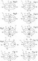
- la
figure 1 représente une vue schématique d'éléments d'un dispositif d'essuyage pour balai d'essuie-glace à deux rampes d'arrosage, - la
figure 2 représente une vue partielle en perspective d'une conduite de chauffage et de transport du dispositif d'essuyage de lafigure 1 , - la
figure 3 représente une section de la conduite de lafigure 2 , - la
figure 4 représente une section d'une variante de la conduite de lafigure 3 , - la
figure 5 représente une section d'une autre variante de la conduite de lafigure 3 , - la
figure 6 représente une section d'une autre variante de la conduite de lafigure 3 , - la
figure 7 représente une section d'une autre variante de la conduite de lafigure 3 , - la
figure 8 représente une section d'une autre variante de la conduite de lafigure 3 , - la
figure 9 représente une section d'une autre variante de la conduite de lafigure 3 , - la
figure 10 représente une section d'une autre variante de la conduite de lafigure 3 , - la
figure 11 représente une section d'une autre variante de la conduite de lafigure 3 , et - la
figure 12 représente une section d'une autre variante de la conduite de lafigure 3 .
- the
figure 1 represents a schematic view of elements of a wiper device for a wiper blade with two spray bars, - the
figure 2 is a partial perspective view of a heating pipe and transport of the wiper device of thefigure 1 , - the
figure 3 represents a section of the conduct of thefigure 2 , - the
figure 4 represents a section of a variant of the conduct of thefigure 3 , - the
figure 5 represents a section of another variant of the conduct of thefigure 3 , - the
figure 6 represents a section of another variant of the conduct of thefigure 3 , - the
figure 7 represents a section of another variant of the conduct of thefigure 3 , - the
figure 8 represents a section of another variant of the conduct of thefigure 3 , - the
figure 9 represents a section of another variant of the conduct of thefigure 3 , - the
figure 10 represents a section of another variant of the conduct of thefigure 3 , - the
figure 11 represents a section of another variant of the conduct of thefigure 3 , and - the
figure 12 represents a section of another variant of the conduct of thefigure 3 .
Sur ces figures, les éléments identiques portent les mêmes numéros de référence.In these figures, the identical elements bear the same reference numbers.
La
Le dispositif d'essuyage 1 comporte en outre une conduite de chauffage et de transport de liquide lave-glace 3 pour alimenter les rampes d'arrosage en liquide lave-glace contenu dans un réservoir du véhicule automobile par l'intermédiaire d'une pompe. On peut utiliser une pompe bidirectionnelle ou deux pompes monodirectionnelles du véhicule automobile (non représentées) pour chaque rampe d'arrosage.The wiper device 1 further comprises a windshield washer fluid heating and
Comme on peut le voir sur les
Un premier canal de circulation du liquide lave-glace 5a est relié d'une part à la première rampe d'arrosage du balai d'essuie-glace 2 et d'autre part à une pompe. Un deuxième canal de circulation du liquide lave-glace 5b est relié d'une part à la deuxième rampe d'arrosage du balai d'essuie-glace 2 et d'autre part à une pompe.A first washing
Les conducteurs électriques 6a, 6b et les canaux de circulation 5a, 5b sont sensiblement parallèles entre eux. Dans ce premier exemple, la périphérie de la section transversale du manchon 4 (à l'extérieur du manchon) présente deux faces opposées centrales plates et deux portions extrêmes arrondies.The
Les conducteurs électriques 6a, 6b présentent des éléments chauffants (le conducteur électrique est par exemple un fil résistif chauffant) ou sont destinés à être connectés à des éléments chauffants d'un dispositif de chauffage du balai d'essuie-glace de sorte que le liquide lave-glace prélevé dans le réservoir par le(s) pompe(s) vers la rampe d'arrosage respective soit chauffé. On obtient ainsi un nettoyage amélioré des surfaces vitrées en chauffant le liquide lave-glace avant qu'il ne soit projeté sur la surface vitrée. Par ailleurs, le liquide lave-glace chauffé participe au dégivrage des surfaces vitrées.The
Pour cela, des conducteurs électriques gainés 6a, 6b dépassent de part et d'autre du manchon 4, pour pouvoir être dénudés à leurs extrémités et connectés ensemble d'un côté et à une alimentation de l'autre côté afin de former une boucle de courant. Pour le raccordement du canal de circulation de liquide lave-glace 5a, on prévoit des raccords à liquides.For this, sheathed
Selon une première variante représentée sur les
En cours d'utilisation, les conducteurs électriques 6a, 6b chauffent le manchon 4 qui chauffe à son tour le liquide lave-glace lors de son écoulement dans les canaux de circulation 5a, 5b entre la pompe et la rampe d'arrosage respective.In use, the
Selon une variante non représentée, un premier conducteur électrique 6a comporte un élément de chauffage et un deuxième conducteur électrique 6b comporte un câble de masse. De même que précédemment, les conducteurs électriques 6a, 6b dépassent de part et d'autre du manchon 4 pour pouvoir être dénudés à leurs extrémités puis connectés ensemble d'un côté et à une alimentation de l'autre côté pour former une boucle de courant. Toutefois, la puissance de chauffage nécessaire est alors deux fois plus importante que dans le premier exemple de réalisation pour obtenir sensiblement la même température du liquide lave-glace. En outre, il est nécessaire de disposer le conducteur électrique comportant l'élément de chauffage entre les canaux de circulation du liquide lave-glace 5a, 5b pour s'assurer de chauffer les deux canaux de circulation du liquide lave-glace 5a, 5b.According to a variant not shown, a first
Selon une autre variante de réalisation, les deux conducteurs électriques 6a, 6b noyés dans le manchon 4 sont destinés à alimenter un dispositif électrique tel qu'un dispositif de chauffage intégré du balai d'essuie-glace 2. On peut torsader les conducteurs électriques car ils ne sont pas destinés au chauffage de la conduite. On utilise ainsi la conduite de chauffage et de transport 3 pour acheminer le liquide lave-glace et l'électricité au balai-essuie glace 2, en fixant la disposition des conducteurs électriques 6a, 6b par rapport aux canaux de circulation de liquide 5a, 5b. En outre, l'implémentation dans le véhicule automobile est facilitée.According to another embodiment, the two
On peut également envisager une combinaison de ces exemples. Ainsi, la
Une première paire de conducteurs électriques 6a, 6b comporte par exemple des éléments de chauffage et une deuxième paire de conducteurs électriques 6c, 6d comporte par exemple des câbles électriques pour l'alimentation d'un dispositif de chauffage intégré du balai d'essuie-glace 2. On peut ainsi chauffer à la fois le liquide lave-glace et le balai d'essuie-glace 2. Le liquide lave-glace, l'électricité et/ou le chauffage peuvent être acheminés dans une même conduite jusqu'à une rampe d'arrosage respective sans obstacle dans le canal de circulation du liquide lave-glace et en limitant l'encombrement et les coûts.A first pair of
On peut en outre prévoir que les deux conducteurs électriques 6a, 6b de la conduite de chauffage et de transport 3 présentant des éléments de chauffage, se prolongent dans le balai d'essuie-glace 2 (voir
Dans un deuxième mode de réalisation, une première paire de conducteurs électriques 6a, 6b comportant des éléments de chauffage sont noyés dans le manchon et au moins une deuxième paire de conducteurs électriques 7a, 7b sont fixés à l'extérieur du manchon 4. Les conducteurs électriques 6a, 6b, noyés dans le manchon 4 sont munis d'éléments chauffants et les conducteurs électriques 7a, 7b, fixés à l'extérieur du manchon 4 permettent par exemple d'alimenter un dispositif de chauffage d'un balai d'essuie-glace.In a second embodiment, a first pair of
Selon une première variante de réalisation représentée en
Selon une deuxième variante de réalisation représentée en
Selon une troisième variante de réalisation représentée en
Selon une quatrième variante de réalisation représentée en
On peut prévoir en outre de séparer les bouts de la conduite de chauffage et de transport 3 en deux extrémités de conduite libres sur une longueur par exemple comprise entre 50 et 100 millimètres de façon à pouvoir être connectées facilement. Les conducteurs électriques noyés dans le manchon 4 sont par exemple disposés de part et d'autre d'un plan médian aux canaux de circulation 5a, 5b de manière que chaque extrémité de conduite libre comprenne un canal de circulation de liquide lave-glace 5a, 5b et au moins un conducteur électrique 6a, 6b.It is furthermore possible to separate the ends of the heating and conveying
Par exemple, les conducteurs électriques 6a, 6b comportant des éléments de chauffage noyés dans le manchon 4 sont disposés sur les bords du manchon 4, aux extrémités de la section (
La conduite de chauffage et de transport 3 peut également présenter une amorce de rupture à au moins un bout de manchon 4 pour séparer une première extrémité de conduite d'une deuxième extrémité de conduite, chaque extrémité de conduite comprenant un canal de circulation du liquide lave-glace 5a, 5b et au moins un conducteur électrique 6a, 6b. L'amorce de rupture permet de faciliter la séparation des extrémités de conduite en bout de manchon, les extrémités séparées pouvant être connectées ensuite à une rampe d'arrosage respective et/ou une pompe respective.The heating and
Selon un premier exemple de réalisation de l'amorce de rupture représenté sur la
Selon un deuxième exemple de réalisation de l'amorce de rupture représenté sur la
La conduite de chauffage et de transport 3 est obtenue par le procédé de fabrication suivant. On insère au moins un conducteur électrique 6a, 6b dans une matière en cours d'extrusion à travers une filière adaptée pour la mise en forme du manchon 4, ce qui permet de diminuer le nombre d'étapes du procédé de fabrication, le rendant très simple et peu couteux. L'implémentation dans le véhicule automobile est simplifié car il suffit de dénuder les conducteurs électriques pour les raccorder sans nécessiter les étapes compliquées d'introduction de ceux-ci dans le manchon à posteriori de l'extrusion. Les conducteurs électriques 6a, 6b peuvent être insérés déjà gainés pour faciliter leur mise en place dans le manchon extrudé. En outre, on peut utiliser des conducteurs électriques nus à noyer dans le manchon extrudé qui sert d'isolant. Dans ce dernier cas, on prévoit un moyen de séparation pour tenir les conducteurs électriques à l'écart l'un de l'autre pour leur insertion dans la filière.The heating and
On peut prévoir pour cela que la conduite soit fabriquée en un seul tenant et que le dispositif d'essuyage comporte des connecteurs électriques et des raccords à liquide pour raccorder respectivement les conducteurs électriques 6a, 6b entre eux et à leur alimentation et les canaux de circulation de liquide lave-glace 5a, 5b à leur pompe ou gicleur(s) d'arrosage respectif.It can be provided for this purpose that the pipe is manufactured in one piece and that the wiper device comprises electrical connectors and liquid fittings for respectively connecting the
Selon un autre exemple de réalisation, on peut fabriquer une conduite de chauffage et de transport en un seul tenant et on sépare ensuite les bouts de la conduite de chauffage et de transport en deux extrémités de conduite libres, chaque extrémité de conduite libre comprenant un canal de circulation de liquide lave-glace 5a, 5b et au moins un conducteur électrique 6a, 6b.According to another embodiment, a heating and transport pipe can be produced in one piece and the ends of the heating and conveying pipe are then separated into two free pipe ends, each free pipe end comprising a channel washer
On peut également prévoir de fabriquer une conduite dont les bouts de conduite sont déjà séparés. Par exemple, on insère un premier conducteur électrique 6a dans une matière en cours d'extrusion à travers une filière adaptée pour la mise en forme d'une première portion de manchon présentant un premier canal de circulation pour le liquide lave-glace 5a. Et, on insère un deuxième conducteur électrique 6b dans une matière en cours d'extrusion à travers une filière adaptée pour la mise en forme d'une deuxième portion de manchon présentant un deuxième canal de circulation pour le liquide lave-glace 5b. Puis, on assemble, par exemple par collage, les première et deuxième portions de manchon entre deux extrémités libres de conduite (
Claims (17)
- A pipe for heating and transporting able to be connected on one hand with a windscreen wiper blade with two spray lines, and on the other hand with a pump to supply the spray lines with washer fluid contained in a reservoir of the motor vehicle by means of a pump comprising: an extruded sleeve (4) with at least two washer fluid circulation channels (5a, 5b), characterized in that at least two electric wires (6a, 6b, 6c, 6d) of said pipe are embedded within the mass of the sleeve (4), the electric wires (6a, 6b) and the circulation channels (5a, 5b) being substantially parallel to each other, the cross-sections of the electric wires being aligned at the center of the sleeve (4) in a median direction with respect to the circulation channels (5a, 5b) or the cross-sections of the embedded electric wires (6a, 6b) and the circulation channels (5a, 5b) are substantially aligned.
- The heating and transport pipe according to claim 1, further comprising two first electric wires (6a, 6b) provided with heating elements embedded in the sleeve (4) between the two circulation channels of the washer fluid (5a, 5b).
- The heating and transport pipe according to claim 2, further comprising two second electric wires (6c, 6d) embedded in the sleeve (4) to power a heating device of a wiper blade.
- The heating and transport pipe according to any one of claims 1 to 3, wherein said sleeve (4) includes a flexible material.
- The heating and transport pipe according to any one of claims 1 to 4, wherein the electric wires (6a, 6b) embedded in the sleeve (4) are positioned at the ends of a cross-section of the sleeve (4).
- The heating and transport pipe according to any one of claims 1 to 5, wherein the cross-section of the sleeve (4) is in the general shape of an "8" and said pipe includes at least one electric wire (7a, 7b, 7c, 7d) fixed to the outside of sleeve (4) in at least one hollow of a concave flank of the "8" shape.
- The heating and transport pipe according to any one of claims 1 to 6, wherein a periphery of the cross-section of the sleeve (4) has two flat central opposite faces and two rounded end portions.
- The heating and transport pipe according to the preceding claim, wherein a notch (9a, 9b) is formed in at least one flat central face of the periphery of the sleeve (4) to clip at least one electric wire (7a-7d) of said heating and transport pipe (3) to the outside of the sleeve (4).
- The heating and transport pipe according to any one of claims 1 to 8, wherein the electric wires (6a, 6b) embedded in the sleeve (4) are positioned on either side of a median plane with respect to the circulation channels (5a, 5b).
- The heating and transport pipe according to the preceding claim, further comprising a weakening rim at least at one end of the sleeve to separate a first pipe end from the second pipe end, each pipe end comprising the washer fluid circulation channel (5a, 5b) and at least one electric wire (6a, 6b).
- The heating and transport pipe according to claims 10 and 7, wherein two flat central opposite faces of a sleeve end have two beveled slots (10a, 10b) at a complementary incline to facilitate the separation of a first and second pipe end.
- The heating and transport device according to claim 10, wherein one sleeve end has a thinner central portion (11) to facilitate the separation of a first and second pipe end.
- A wiper device for a glass surface of an automobile, comprising a wiper blade (2) provided with first and second spray lines on either side of the wiper blade, characterized in that it further comprises a heating and transport pipe according to any one of claims 1 to 12, wherein a first washer fluid circulation channel (5a) is connected on the one hand to said first spray line of the wiper blade (2), and on the other hand is configured for connection to a pump, and wherein the second circulation channel for the washer fluid (5b) is connected on the one hand to said second spray line of the wiper blade (2) and is configured for connection on the other hand to a pump.
- The wiper device according to claim 13, wherein two electric wires (6a, 6b)of said heating and transport pipe have heating elements extending in the wiper blade (2) .
- A method for manufacturing a pipe for heating and transporting a washer fluid according to any one of claims 1 to 12, the method comprising: inserting at least one electric wire (6a, 6b) in a material being extruded through a channel suitable for shaping said sleeve (4a).
- The manufacturing method according to claim 15, wherein the extruded sleeve (4) has two washer fluid circulation channels (5a, 5b), and the ends of the sleeve are then separated into first and second free pipe ends each comprising the washer fluid circulation channel (5a, 5b) and the at least one electric wire (6a, 6b).
- The manufacturing method according to claim 15, wherein the first electric wire (6a) is inserted into a material during extrusion through a channel suitable for shaping a first sleeve portion having a first washer fluid circulation channel (5a), and a second electric wire (6b) is inserted into a material during extrusion through a channel suitable for shaping a second sleeve portion having a second washer fluid circulation channel (5b), wherein said first and second sleeve portions are assembled between two free pipe ends.
Applications Claiming Priority (2)
| Application Number | Priority Date | Filing Date | Title |
|---|---|---|---|
| FR1003849A FR2965235B1 (en) | 2010-09-29 | 2010-09-29 | HEATING AND TRANSPORTING CONDUIT OF A WINDSCREEN ICE WIPER LIQUID WITH TWO RINSING RINSES, WIPING DEVICE AND METHOD OF MANUFACTURING |
| PCT/EP2011/063552 WO2012041581A1 (en) | 2010-09-29 | 2011-08-05 | Pipe for heating and transporting a washer fluid for a windscreen wiper arm with two spray lines, wiper device and method of manufacture |
Publications (2)
| Publication Number | Publication Date |
|---|---|
| EP2621774A1 EP2621774A1 (en) | 2013-08-07 |
| EP2621774B1 true EP2621774B1 (en) | 2018-05-30 |
Family
ID=44009972
Family Applications (1)
| Application Number | Title | Priority Date | Filing Date |
|---|---|---|---|
| EP11741214.8A Active EP2621774B1 (en) | 2010-09-29 | 2011-08-05 | Pipe for heating and transporting a washer fluid for a windscreen wiper arm with two spray lines, wiper device and method of manufacture |
Country Status (8)
| Country | Link |
|---|---|
| US (1) | US10507802B2 (en) |
| EP (1) | EP2621774B1 (en) |
| JP (1) | JP6109739B2 (en) |
| KR (1) | KR20130124438A (en) |
| CA (1) | CA2811826A1 (en) |
| FR (1) | FR2965235B1 (en) |
| RU (1) | RU2576360C2 (en) |
| WO (1) | WO2012041581A1 (en) |
Families Citing this family (17)
| Publication number | Priority date | Publication date | Assignee | Title |
|---|---|---|---|---|
| FR2984258B1 (en) * | 2011-12-19 | 2016-08-05 | Valeo Systemes Dessuyage | ELECTRICAL AND HYDRAULIC CONNECTION DEVICE FOR A SYSTEM FOR SUPPLYING AND / OR DISTRIBUTING IN WINDSCREEN WINDOW |
| FR2984257B1 (en) * | 2011-12-19 | 2016-08-05 | Valeo Systemes Dessuyage | DEVICE FOR TRANSPORTING AND HEATING A LIQUID FOR A WIPING SYSTEM OF A GLASS OF A VEHICLE |
| FR3002507B1 (en) | 2013-02-28 | 2016-09-09 | Valeo Systemes Dessuyage | DEVICE FOR DISPENSING WINDSCREEN WASHING LIQUID FOR MOTOR VEHICLE WIPER BLADES |
| FR3008052B1 (en) * | 2013-07-03 | 2015-07-03 | Valeo Systemes Dessuyage | HEATING DEVICE FOR WIPER BLADE OF A VEHICLE AND WIPER BLADE COMPRISING THE SAME |
| JP6016126B2 (en) * | 2013-08-07 | 2016-10-26 | 住友電装株式会社 | Feeding cable routing structure to heating wire terminal |
| BR112016007441A2 (en) * | 2013-10-03 | 2019-12-17 | M I Drilling Fluids Uk Ltd | elongated appliance, appliance, and method |
| FR3014388B1 (en) * | 2013-12-05 | 2017-07-14 | Valeo Systemes Dessuyage | METHOD FOR MANUFACTURING A HEATING ELEMENT FOR A WIPER BLADE OF A VEHICLE |
| FR3017844B1 (en) * | 2014-02-24 | 2016-03-04 | Valeo Systemes Dessuyage | WIPER BLADE FOR VEHICLE WINDOWS |
| US9932017B2 (en) | 2014-11-05 | 2018-04-03 | Asmo Co., Ltd. | Vehicle wiper |
| JP6471544B2 (en) * | 2015-03-09 | 2019-02-20 | 株式会社デンソー | Vehicle wiper |
| FR3039483B1 (en) * | 2015-07-27 | 2019-01-25 | Valeo Systemes D'essuyage | CONVEYANCE FOR TRANSPORTING A REDUCED ICEWASHING LIQUID COMPRISING AT LEAST ONE COAXIAL ELECTRIC WIRE |
| FR3039484B1 (en) * | 2015-07-27 | 2017-08-18 | Valeo Systemes Dessuyage | SYSTEM FOR DISPENSING AND HEATING WINDSCREEN WASHING LIQUID FOR WIPER BLADES |
| FR3039487B1 (en) | 2015-07-29 | 2017-08-18 | Valeo Systemes Dessuyage | HEATING DEVICE OF A WINDSCREEN DISPENSING SYSTEM FOR MOTOR VEHICLE WIPER BLADES AND METHOD OF ASSEMBLING THE SAME |
| FR3040950B1 (en) * | 2015-09-16 | 2017-09-08 | Valeo Systemes Dessuyage | LIQUID DRIVE ADAPTER AND MOTOR VEHICLE WIPER BLADE BRAND LIQUID DISPENSING DEVICE |
| DE102016109396A1 (en) * | 2016-05-23 | 2017-11-23 | Valeo Systèmes d'Essuyage | Heating device for wiping systems in vehicles and wiper system |
| FR3091242B1 (en) * | 2018-12-26 | 2023-11-17 | Valeo Systemes Dessuyage | Process for cleaning an optical surface of a motor vehicle |
| CN119056860B (en) * | 2024-10-08 | 2025-11-28 | 中国科学院新疆生态与地理研究所 | Mine heavy metal contaminated soil restoration device and restoration method thereof |
Citations (2)
| Publication number | Priority date | Publication date | Assignee | Title |
|---|---|---|---|---|
| US4038519A (en) * | 1973-11-15 | 1977-07-26 | Rhone-Poulenc S.A. | Electrically heated flexible tube having temperature measuring probe |
| WO2009118286A1 (en) * | 2008-03-26 | 2009-10-01 | Valeo Systemes D'essuyage | Wiper for vehicle windows |
Family Cites Families (22)
| Publication number | Priority date | Publication date | Assignee | Title |
|---|---|---|---|---|
| US3530525A (en) * | 1968-10-21 | 1970-09-29 | Louis Abel | Heated windshield wiper |
| US4194536A (en) * | 1976-12-09 | 1980-03-25 | Eaton Corporation | Composite tubing product |
| JPS5727149U (en) * | 1980-07-23 | 1982-02-12 | ||
| DE3374537D1 (en) * | 1982-09-24 | 1987-12-23 | Onofrio Rocchitelli | Heating device for the glass washing fluid of motor vehicles and the like |
| US4670933A (en) * | 1985-10-28 | 1987-06-09 | Tibor Toplenszky | Heated windshield wiper |
| JPS63126299A (en) * | 1987-10-23 | 1988-05-30 | カネボウ株式会社 | Molded article for shielding |
| DE3824483A1 (en) * | 1988-07-20 | 1990-01-25 | Bosch Gmbh Robert | WIPING DEVICE FOR WINDOWS OF MOTOR VEHICLES |
| JPH0293614A (en) * | 1988-09-30 | 1990-04-04 | Mitsubishi Cable Ind Ltd | Optical fiber cable |
| DE3907968A1 (en) * | 1989-03-11 | 1990-09-13 | Swf Auto Electric Gmbh | WINDOW CLEANING SYSTEM |
| DE4117109C2 (en) * | 1991-05-25 | 1996-04-04 | Teves Gmbh Alfred | Wiping and washing system, in particular for windows of motor vehicles |
| DE4118926C2 (en) * | 1991-06-08 | 1997-08-21 | Vdo Schindling | Supply line for the transport of cleaning fluid |
| DE4402372A1 (en) * | 1994-01-27 | 1995-08-03 | Vdo Schindling | Washing fluid feed line for washing plant |
| JPH09182231A (en) * | 1995-12-22 | 1997-07-11 | Aichi Sharyo Kogyo Kk | Cable cutting device |
| JPH09207197A (en) * | 1996-01-31 | 1997-08-12 | Nippon Petrochem Co Ltd | Method for forming thermoplastic resin pipe containing reinforcing strip and apparatus used therefor |
| US5791377A (en) * | 1996-07-08 | 1998-08-11 | Yazaki Corporation | Electrically heated conduit |
| JP3992361B2 (en) * | 1998-05-26 | 2007-10-17 | 杉本電器株式会社 | Code processing apparatus and code processing method |
| DE19833142A1 (en) * | 1998-07-23 | 2000-02-03 | Mannesmann Vdo Ag | Window cleaning system |
| EP1040973B1 (en) * | 1999-03-31 | 2005-04-20 | A. Raymond & Cie | Electrically heated hose for windscreen cleaning device |
| WO2002088587A1 (en) * | 2001-04-27 | 2002-11-07 | Fiberspar Corporation | Buoyancy control systems for tubes |
| US7711251B2 (en) * | 2006-12-27 | 2010-05-04 | Barkey Gmbh & Co. Kg | Device for temperature controlled heating of a fluid line |
| DE102008049270A1 (en) * | 2008-09-26 | 2010-04-01 | Valeo Systèmes d'Essuyage | Wiper arm / wiper blade connection, wiper blade and windscreen wiper system |
| DE102008049269B4 (en) * | 2008-09-26 | 2020-08-27 | Valeo Systèmes d'Essuyage | Wiper arm / wiper blade connection and wiper blade |
-
2010
- 2010-09-29 FR FR1003849A patent/FR2965235B1/en active Active
-
2011
- 2011-08-05 RU RU2013119648/11A patent/RU2576360C2/en not_active IP Right Cessation
- 2011-08-05 US US13/876,481 patent/US10507802B2/en active Active
- 2011-08-05 JP JP2013530648A patent/JP6109739B2/en not_active Expired - Fee Related
- 2011-08-05 CA CA2811826A patent/CA2811826A1/en not_active Abandoned
- 2011-08-05 EP EP11741214.8A patent/EP2621774B1/en active Active
- 2011-08-05 KR KR1020137010540A patent/KR20130124438A/en not_active Withdrawn
- 2011-08-05 WO PCT/EP2011/063552 patent/WO2012041581A1/en not_active Ceased
Patent Citations (2)
| Publication number | Priority date | Publication date | Assignee | Title |
|---|---|---|---|---|
| US4038519A (en) * | 1973-11-15 | 1977-07-26 | Rhone-Poulenc S.A. | Electrically heated flexible tube having temperature measuring probe |
| WO2009118286A1 (en) * | 2008-03-26 | 2009-10-01 | Valeo Systemes D'essuyage | Wiper for vehicle windows |
Also Published As
| Publication number | Publication date |
|---|---|
| CA2811826A1 (en) | 2012-04-05 |
| RU2576360C2 (en) | 2016-02-27 |
| JP2013538743A (en) | 2013-10-17 |
| KR20130124438A (en) | 2013-11-13 |
| WO2012041581A1 (en) | 2012-04-05 |
| FR2965235A1 (en) | 2012-03-30 |
| EP2621774A1 (en) | 2013-08-07 |
| US10507802B2 (en) | 2019-12-17 |
| JP6109739B2 (en) | 2017-04-05 |
| RU2013119648A (en) | 2014-11-10 |
| US20130219647A1 (en) | 2013-08-29 |
| FR2965235B1 (en) | 2018-01-26 |
Similar Documents
| Publication | Publication Date | Title |
|---|---|---|
| EP2621774B1 (en) | Pipe for heating and transporting a washer fluid for a windscreen wiper arm with two spray lines, wiper device and method of manufacture | |
| EP2607190B1 (en) | heated hydraulic interface for a vehicle windshield washing liquid distribution and/or supply system. | |
| EP2961643B1 (en) | Washing liquid dispensing apparatus for vehicle windscreen wipers | |
| FR2971470A1 (en) | HEATING AND TRANSPORTING CONDUCT OF ICE-LIQUID WASHING MACHINE FOR AUTOMOTIVE MOTOR VEHICLE WIPER BLADE | |
| WO2012072299A1 (en) | Assembly comprising an end piece of a windshield wiper arm and an electrical connector | |
| EP2876004A1 (en) | Heating hydraulic interface for a system for supplying and/or dispensing windscreen-washer liquid of an automobile | |
| CA2799262A1 (en) | Electrical and hydraulic connection device for a windshield washer fluid supply/distribution system | |
| EP2910439B1 (en) | Heating device for windscreen-wiper blade of a vehicle, windscreen-wiper blade comprising same, and method for assembling such a windscreen-wiper blade | |
| EP2813402A1 (en) | Wiping system enabling the spraying of a fluid for cleaning and/or de-icing at a windscreen-wiper blade | |
| EP2777996A1 (en) | Motor vehicle windscreen wiper fluid distribution device | |
| FR2971471A1 (en) | ICE-LIQUID DISPENSING DEVICE FOR MOTOR VEHICLE WIPER BLADES AND METHOD FOR ASSEMBLING SUCH A DISPENSING DEVICE | |
| CA2874036A1 (en) | Connectors for a vehicle wiper blade | |
| EP2934959B1 (en) | System for distributing washer fluid for motor vehicle windscreen wipers | |
| EP2887765B1 (en) | Heat-conducting wire element for manufacturing a heating pipe and for conveying a windscreen washer liquid with controlled linear heating power, related heating pipe and wiping device | |
| EP2734423B1 (en) | Connector support and liquid distributing apparatus for vehicle windscreen wipers | |
| FR3039483A1 (en) | CONDUCT OF TRANSPORTING A REDUCED ICE-WASHING LIQUID HAVING AT LEAST ONE COAXIAL ELECTRIC WIRE. | |
| EP3144189A1 (en) | Adapter for a conduit for liquid and device for the distribution of liquid in a motor vehicle | |
| CH631293A5 (en) | ELECTRIC CONTACT. | |
| FR2974050A1 (en) | Joint for windscreen washer pipe system to realize de-icing of windscreen washer liquid delivering nozzles in car, has three electrical connectors located in respective outer sides of three pipes to assure contact of fourth connector | |
| FR3014390A1 (en) | HEATING DEVICE FOR WIPER BLADE OF A VEHICLE AND WIPER BLADE COMPRISING THE SAME | |
| FR3130226A1 (en) | Wiper fluidic linkage device | |
| FR3046972A1 (en) | HYDRAULIC HEATING INTERFACE FOR A SYSTEM FOR THE SUPPLY AND / OR DISTRIBUTION OF LIQUID WASHING ICE OF MOTOR VEHICLE | |
| FR3123032A1 (en) | Wiper blade device and wiper system | |
| FR3014391A1 (en) | FLUID CONNECTION FOR VEHICLE ICE WIPER SYSTEM |
Legal Events
| Date | Code | Title | Description |
|---|---|---|---|
| PUAI | Public reference made under article 153(3) epc to a published international application that has entered the european phase |
Free format text: ORIGINAL CODE: 0009012 |
|
| 17P | Request for examination filed |
Effective date: 20130325 |
|
| AK | Designated contracting states |
Kind code of ref document: A1 Designated state(s): AL AT BE BG CH CY CZ DE DK EE ES FI FR GB GR HR HU IE IS IT LI LT LU LV MC MK MT NL NO PL PT RO RS SE SI SK SM TR |
|
| RIN1 | Information on inventor provided before grant (corrected) |
Inventor name: COINTEREAU, JEAN-FRANCOIS Inventor name: THEBAULT, DENIS Inventor name: JARASSON, JEAN-MICHEL Inventor name: CALLUIERE, JOHAN Inventor name: NEGRE, PIERRE-EMMANUEL |
|
| DAX | Request for extension of the european patent (deleted) | ||
| 17Q | First examination report despatched |
Effective date: 20151126 |
|
| GRAP | Despatch of communication of intention to grant a patent |
Free format text: ORIGINAL CODE: EPIDOSNIGR1 |
|
| INTG | Intention to grant announced |
Effective date: 20180111 |
|
| GRAS | Grant fee paid |
Free format text: ORIGINAL CODE: EPIDOSNIGR3 |
|
| GRAA | (expected) grant |
Free format text: ORIGINAL CODE: 0009210 |
|
| AK | Designated contracting states |
Kind code of ref document: B1 Designated state(s): AL AT BE BG CH CY CZ DE DK EE ES FI FR GB GR HR HU IE IS IT LI LT LU LV MC MK MT NL NO PL PT RO RS SE SI SK SM TR |
|
| REG | Reference to a national code |
Ref country code: GB Ref legal event code: FG4D Free format text: NOT ENGLISH |
|
| REG | Reference to a national code |
Ref country code: CH Ref legal event code: EP |
|
| REG | Reference to a national code |
Ref country code: AT Ref legal event code: REF Ref document number: 1003288 Country of ref document: AT Kind code of ref document: T Effective date: 20180615 |
|
| REG | Reference to a national code |
Ref country code: DE Ref legal event code: R096 Ref document number: 602011048798 Country of ref document: DE |
|
| REG | Reference to a national code |
Ref country code: IE Ref legal event code: FG4D Free format text: LANGUAGE OF EP DOCUMENT: FRENCH |
|
| REG | Reference to a national code |
Ref country code: SE Ref legal event code: TRGR |
|
| REG | Reference to a national code |
Ref country code: FR Ref legal event code: PLFP Year of fee payment: 8 |
|
| REG | Reference to a national code |
Ref country code: NL Ref legal event code: MP Effective date: 20180530 |
|
| REG | Reference to a national code |
Ref country code: LT Ref legal event code: MG4D |
|
| PG25 | Lapsed in a contracting state [announced via postgrant information from national office to epo] |
Ref country code: ES Free format text: LAPSE BECAUSE OF FAILURE TO SUBMIT A TRANSLATION OF THE DESCRIPTION OR TO PAY THE FEE WITHIN THE PRESCRIBED TIME-LIMIT Effective date: 20180530 Ref country code: BG Free format text: LAPSE BECAUSE OF FAILURE TO SUBMIT A TRANSLATION OF THE DESCRIPTION OR TO PAY THE FEE WITHIN THE PRESCRIBED TIME-LIMIT Effective date: 20180830 Ref country code: LT Free format text: LAPSE BECAUSE OF FAILURE TO SUBMIT A TRANSLATION OF THE DESCRIPTION OR TO PAY THE FEE WITHIN THE PRESCRIBED TIME-LIMIT Effective date: 20180530 Ref country code: CY Free format text: LAPSE BECAUSE OF FAILURE TO SUBMIT A TRANSLATION OF THE DESCRIPTION OR TO PAY THE FEE WITHIN THE PRESCRIBED TIME-LIMIT Effective date: 20180530 Ref country code: FI Free format text: LAPSE BECAUSE OF FAILURE TO SUBMIT A TRANSLATION OF THE DESCRIPTION OR TO PAY THE FEE WITHIN THE PRESCRIBED TIME-LIMIT Effective date: 20180530 Ref country code: NO Free format text: LAPSE BECAUSE OF FAILURE TO SUBMIT A TRANSLATION OF THE DESCRIPTION OR TO PAY THE FEE WITHIN THE PRESCRIBED TIME-LIMIT Effective date: 20180830 |
|
| PGFP | Annual fee paid to national office [announced via postgrant information from national office to epo] |
Ref country code: IT Payment date: 20180919 Year of fee payment: 15 |
|
| PG25 | Lapsed in a contracting state [announced via postgrant information from national office to epo] |
Ref country code: RS Free format text: LAPSE BECAUSE OF FAILURE TO SUBMIT A TRANSLATION OF THE DESCRIPTION OR TO PAY THE FEE WITHIN THE PRESCRIBED TIME-LIMIT Effective date: 20180530 Ref country code: LV Free format text: LAPSE BECAUSE OF FAILURE TO SUBMIT A TRANSLATION OF THE DESCRIPTION OR TO PAY THE FEE WITHIN THE PRESCRIBED TIME-LIMIT Effective date: 20180530 Ref country code: HR Free format text: LAPSE BECAUSE OF FAILURE TO SUBMIT A TRANSLATION OF THE DESCRIPTION OR TO PAY THE FEE WITHIN THE PRESCRIBED TIME-LIMIT Effective date: 20180530 Ref country code: GR Free format text: LAPSE BECAUSE OF FAILURE TO SUBMIT A TRANSLATION OF THE DESCRIPTION OR TO PAY THE FEE WITHIN THE PRESCRIBED TIME-LIMIT Effective date: 20180831 |
|
| REG | Reference to a national code |
Ref country code: AT Ref legal event code: MK05 Ref document number: 1003288 Country of ref document: AT Kind code of ref document: T Effective date: 20180530 |
|
| PG25 | Lapsed in a contracting state [announced via postgrant information from national office to epo] |
Ref country code: NL Free format text: LAPSE BECAUSE OF FAILURE TO SUBMIT A TRANSLATION OF THE DESCRIPTION OR TO PAY THE FEE WITHIN THE PRESCRIBED TIME-LIMIT Effective date: 20180530 |
|
| PG25 | Lapsed in a contracting state [announced via postgrant information from national office to epo] |
Ref country code: SK Free format text: LAPSE BECAUSE OF FAILURE TO SUBMIT A TRANSLATION OF THE DESCRIPTION OR TO PAY THE FEE WITHIN THE PRESCRIBED TIME-LIMIT Effective date: 20180530 Ref country code: RO Free format text: LAPSE BECAUSE OF FAILURE TO SUBMIT A TRANSLATION OF THE DESCRIPTION OR TO PAY THE FEE WITHIN THE PRESCRIBED TIME-LIMIT Effective date: 20180530 Ref country code: PL Free format text: LAPSE BECAUSE OF FAILURE TO SUBMIT A TRANSLATION OF THE DESCRIPTION OR TO PAY THE FEE WITHIN THE PRESCRIBED TIME-LIMIT Effective date: 20180530 Ref country code: CZ Free format text: LAPSE BECAUSE OF FAILURE TO SUBMIT A TRANSLATION OF THE DESCRIPTION OR TO PAY THE FEE WITHIN THE PRESCRIBED TIME-LIMIT Effective date: 20180530 Ref country code: AT Free format text: LAPSE BECAUSE OF FAILURE TO SUBMIT A TRANSLATION OF THE DESCRIPTION OR TO PAY THE FEE WITHIN THE PRESCRIBED TIME-LIMIT Effective date: 20180530 Ref country code: EE Free format text: LAPSE BECAUSE OF FAILURE TO SUBMIT A TRANSLATION OF THE DESCRIPTION OR TO PAY THE FEE WITHIN THE PRESCRIBED TIME-LIMIT Effective date: 20180530 Ref country code: DK Free format text: LAPSE BECAUSE OF FAILURE TO SUBMIT A TRANSLATION OF THE DESCRIPTION OR TO PAY THE FEE WITHIN THE PRESCRIBED TIME-LIMIT Effective date: 20180530 |
|
| PG25 | Lapsed in a contracting state [announced via postgrant information from national office to epo] |
Ref country code: IT Free format text: LAPSE BECAUSE OF FAILURE TO SUBMIT A TRANSLATION OF THE DESCRIPTION OR TO PAY THE FEE WITHIN THE PRESCRIBED TIME-LIMIT Effective date: 20180530 Ref country code: SM Free format text: LAPSE BECAUSE OF FAILURE TO SUBMIT A TRANSLATION OF THE DESCRIPTION OR TO PAY THE FEE WITHIN THE PRESCRIBED TIME-LIMIT Effective date: 20180530 |
|
| REG | Reference to a national code |
Ref country code: DE Ref legal event code: R097 Ref document number: 602011048798 Country of ref document: DE |
|
| PG25 | Lapsed in a contracting state [announced via postgrant information from national office to epo] |
Ref country code: MC Free format text: LAPSE BECAUSE OF FAILURE TO SUBMIT A TRANSLATION OF THE DESCRIPTION OR TO PAY THE FEE WITHIN THE PRESCRIBED TIME-LIMIT Effective date: 20180530 |
|
| REG | Reference to a national code |
Ref country code: CH Ref legal event code: PL |
|
| PLBE | No opposition filed within time limit |
Free format text: ORIGINAL CODE: 0009261 |
|
| STAA | Information on the status of an ep patent application or granted ep patent |
Free format text: STATUS: NO OPPOSITION FILED WITHIN TIME LIMIT |
|
| PG25 | Lapsed in a contracting state [announced via postgrant information from national office to epo] |
Ref country code: LU Free format text: LAPSE BECAUSE OF NON-PAYMENT OF DUE FEES Effective date: 20180805 Ref country code: LI Free format text: LAPSE BECAUSE OF NON-PAYMENT OF DUE FEES Effective date: 20180831 Ref country code: CH Free format text: LAPSE BECAUSE OF NON-PAYMENT OF DUE FEES Effective date: 20180831 |
|
| 26N | No opposition filed |
Effective date: 20190301 |
|
| REG | Reference to a national code |
Ref country code: IE Ref legal event code: MM4A |
|
| PG25 | Lapsed in a contracting state [announced via postgrant information from national office to epo] |
Ref country code: SI Free format text: LAPSE BECAUSE OF FAILURE TO SUBMIT A TRANSLATION OF THE DESCRIPTION OR TO PAY THE FEE WITHIN THE PRESCRIBED TIME-LIMIT Effective date: 20180530 |
|
| PG25 | Lapsed in a contracting state [announced via postgrant information from national office to epo] |
Ref country code: IE Free format text: LAPSE BECAUSE OF NON-PAYMENT OF DUE FEES Effective date: 20180805 |
|
| PGFP | Annual fee paid to national office [announced via postgrant information from national office to epo] |
Ref country code: SE Payment date: 20190809 Year of fee payment: 9 |
|
| PG25 | Lapsed in a contracting state [announced via postgrant information from national office to epo] |
Ref country code: AL Free format text: LAPSE BECAUSE OF FAILURE TO SUBMIT A TRANSLATION OF THE DESCRIPTION OR TO PAY THE FEE WITHIN THE PRESCRIBED TIME-LIMIT Effective date: 20180530 |
|
| PGFP | Annual fee paid to national office [announced via postgrant information from national office to epo] |
Ref country code: GB Payment date: 20190821 Year of fee payment: 9 |
|
| PG25 | Lapsed in a contracting state [announced via postgrant information from national office to epo] |
Ref country code: MT Free format text: LAPSE BECAUSE OF FAILURE TO SUBMIT A TRANSLATION OF THE DESCRIPTION OR TO PAY THE FEE WITHIN THE PRESCRIBED TIME-LIMIT Effective date: 20180530 |
|
| PG25 | Lapsed in a contracting state [announced via postgrant information from national office to epo] |
Ref country code: TR Free format text: LAPSE BECAUSE OF FAILURE TO SUBMIT A TRANSLATION OF THE DESCRIPTION OR TO PAY THE FEE WITHIN THE PRESCRIBED TIME-LIMIT Effective date: 20180530 |
|
| PG25 | Lapsed in a contracting state [announced via postgrant information from national office to epo] |
Ref country code: HU Free format text: LAPSE BECAUSE OF FAILURE TO SUBMIT A TRANSLATION OF THE DESCRIPTION OR TO PAY THE FEE WITHIN THE PRESCRIBED TIME-LIMIT; INVALID AB INITIO Effective date: 20110805 Ref country code: PT Free format text: LAPSE BECAUSE OF FAILURE TO SUBMIT A TRANSLATION OF THE DESCRIPTION OR TO PAY THE FEE WITHIN THE PRESCRIBED TIME-LIMIT Effective date: 20180530 |
|
| REG | Reference to a national code |
Ref country code: BE Ref legal event code: MM Effective date: 20190831 |
|
| PG25 | Lapsed in a contracting state [announced via postgrant information from national office to epo] |
Ref country code: MK Free format text: LAPSE BECAUSE OF NON-PAYMENT OF DUE FEES Effective date: 20180530 |
|
| PG25 | Lapsed in a contracting state [announced via postgrant information from national office to epo] |
Ref country code: FR Free format text: LAPSE BECAUSE OF NON-PAYMENT OF DUE FEES Effective date: 20190831 Ref country code: IS Free format text: LAPSE BECAUSE OF FAILURE TO SUBMIT A TRANSLATION OF THE DESCRIPTION OR TO PAY THE FEE WITHIN THE PRESCRIBED TIME-LIMIT Effective date: 20180930 |
|
| PG25 | Lapsed in a contracting state [announced via postgrant information from national office to epo] |
Ref country code: BE Free format text: LAPSE BECAUSE OF NON-PAYMENT OF DUE FEES Effective date: 20190831 |
|
| REG | Reference to a national code |
Ref country code: SE Ref legal event code: EUG |
|
| GBPC | Gb: european patent ceased through non-payment of renewal fee |
Effective date: 20200805 |
|
| PG25 | Lapsed in a contracting state [announced via postgrant information from national office to epo] |
Ref country code: SE Free format text: LAPSE BECAUSE OF NON-PAYMENT OF DUE FEES Effective date: 20200806 |
|
| PG25 | Lapsed in a contracting state [announced via postgrant information from national office to epo] |
Ref country code: GB Free format text: LAPSE BECAUSE OF NON-PAYMENT OF DUE FEES Effective date: 20200805 |
|
| P01 | Opt-out of the competence of the unified patent court (upc) registered |
Effective date: 20230528 |
|
| PGFP | Annual fee paid to national office [announced via postgrant information from national office to epo] |
Ref country code: DE Payment date: 20250812 Year of fee payment: 15 |