EP2600803B1 - Flexible helical stent having intermediated non-helical region - Google Patents
Flexible helical stent having intermediated non-helical region Download PDFInfo
- Publication number
- EP2600803B1 EP2600803B1 EP11743732.7A EP11743732A EP2600803B1 EP 2600803 B1 EP2600803 B1 EP 2600803B1 EP 11743732 A EP11743732 A EP 11743732A EP 2600803 B1 EP2600803 B1 EP 2600803B1
- Authority
- EP
- European Patent Office
- Prior art keywords
- stent
- strut
- flexible stent
- helical
- flexible
- Prior art date
- Legal status (The legal status is an assumption and is not a legal conclusion. Google has not performed a legal analysis and makes no representation as to the accuracy of the status listed.)
- Active
Links
Images


Classifications
-
- A—HUMAN NECESSITIES
- A61—MEDICAL OR VETERINARY SCIENCE; HYGIENE
- A61F—FILTERS IMPLANTABLE INTO BLOOD VESSELS; PROSTHESES; DEVICES PROVIDING PATENCY TO, OR PREVENTING COLLAPSING OF, TUBULAR STRUCTURES OF THE BODY, e.g. STENTS; ORTHOPAEDIC, NURSING OR CONTRACEPTIVE DEVICES; FOMENTATION; TREATMENT OR PROTECTION OF EYES OR EARS; BANDAGES, DRESSINGS OR ABSORBENT PADS; FIRST-AID KITS
- A61F2/00—Filters implantable into blood vessels; Prostheses, i.e. artificial substitutes or replacements for parts of the body; Appliances for connecting them with the body; Devices providing patency to, or preventing collapsing of, tubular structures of the body, e.g. stents
- A61F2/82—Devices providing patency to, or preventing collapsing of, tubular structures of the body, e.g. stents
- A61F2/86—Stents in a form characterised by the wire-like elements; Stents in the form characterised by a net-like or mesh-like structure
- A61F2/90—Stents in a form characterised by the wire-like elements; Stents in the form characterised by a net-like or mesh-like structure characterised by a net-like or mesh-like structure
- A61F2/91—Stents in a form characterised by the wire-like elements; Stents in the form characterised by a net-like or mesh-like structure characterised by a net-like or mesh-like structure made from perforated sheets or tubes, e.g. perforated by laser cuts or etched holes
- A61F2/915—Stents in a form characterised by the wire-like elements; Stents in the form characterised by a net-like or mesh-like structure characterised by a net-like or mesh-like structure made from perforated sheets or tubes, e.g. perforated by laser cuts or etched holes with bands having a meander structure, adjacent bands being connected to each other
-
- A—HUMAN NECESSITIES
- A61—MEDICAL OR VETERINARY SCIENCE; HYGIENE
- A61F—FILTERS IMPLANTABLE INTO BLOOD VESSELS; PROSTHESES; DEVICES PROVIDING PATENCY TO, OR PREVENTING COLLAPSING OF, TUBULAR STRUCTURES OF THE BODY, e.g. STENTS; ORTHOPAEDIC, NURSING OR CONTRACEPTIVE DEVICES; FOMENTATION; TREATMENT OR PROTECTION OF EYES OR EARS; BANDAGES, DRESSINGS OR ABSORBENT PADS; FIRST-AID KITS
- A61F2/00—Filters implantable into blood vessels; Prostheses, i.e. artificial substitutes or replacements for parts of the body; Appliances for connecting them with the body; Devices providing patency to, or preventing collapsing of, tubular structures of the body, e.g. stents
- A61F2/82—Devices providing patency to, or preventing collapsing of, tubular structures of the body, e.g. stents
- A61F2/86—Stents in a form characterised by the wire-like elements; Stents in the form characterised by a net-like or mesh-like structure
- A61F2/88—Stents in a form characterised by the wire-like elements; Stents in the form characterised by a net-like or mesh-like structure the wire-like elements formed as helical or spiral coils
-
- A—HUMAN NECESSITIES
- A61—MEDICAL OR VETERINARY SCIENCE; HYGIENE
- A61F—FILTERS IMPLANTABLE INTO BLOOD VESSELS; PROSTHESES; DEVICES PROVIDING PATENCY TO, OR PREVENTING COLLAPSING OF, TUBULAR STRUCTURES OF THE BODY, e.g. STENTS; ORTHOPAEDIC, NURSING OR CONTRACEPTIVE DEVICES; FOMENTATION; TREATMENT OR PROTECTION OF EYES OR EARS; BANDAGES, DRESSINGS OR ABSORBENT PADS; FIRST-AID KITS
- A61F2/00—Filters implantable into blood vessels; Prostheses, i.e. artificial substitutes or replacements for parts of the body; Appliances for connecting them with the body; Devices providing patency to, or preventing collapsing of, tubular structures of the body, e.g. stents
- A61F2/82—Devices providing patency to, or preventing collapsing of, tubular structures of the body, e.g. stents
- A61F2/86—Stents in a form characterised by the wire-like elements; Stents in the form characterised by a net-like or mesh-like structure
- A61F2/90—Stents in a form characterised by the wire-like elements; Stents in the form characterised by a net-like or mesh-like structure characterised by a net-like or mesh-like structure
- A61F2/91—Stents in a form characterised by the wire-like elements; Stents in the form characterised by a net-like or mesh-like structure characterised by a net-like or mesh-like structure made from perforated sheets or tubes, e.g. perforated by laser cuts or etched holes
- A61F2/915—Stents in a form characterised by the wire-like elements; Stents in the form characterised by a net-like or mesh-like structure characterised by a net-like or mesh-like structure made from perforated sheets or tubes, e.g. perforated by laser cuts or etched holes with bands having a meander structure, adjacent bands being connected to each other
- A61F2002/91508—Stents in a form characterised by the wire-like elements; Stents in the form characterised by a net-like or mesh-like structure characterised by a net-like or mesh-like structure made from perforated sheets or tubes, e.g. perforated by laser cuts or etched holes with bands having a meander structure, adjacent bands being connected to each other the meander having a difference in amplitude along the band
-
- A—HUMAN NECESSITIES
- A61—MEDICAL OR VETERINARY SCIENCE; HYGIENE
- A61F—FILTERS IMPLANTABLE INTO BLOOD VESSELS; PROSTHESES; DEVICES PROVIDING PATENCY TO, OR PREVENTING COLLAPSING OF, TUBULAR STRUCTURES OF THE BODY, e.g. STENTS; ORTHOPAEDIC, NURSING OR CONTRACEPTIVE DEVICES; FOMENTATION; TREATMENT OR PROTECTION OF EYES OR EARS; BANDAGES, DRESSINGS OR ABSORBENT PADS; FIRST-AID KITS
- A61F2/00—Filters implantable into blood vessels; Prostheses, i.e. artificial substitutes or replacements for parts of the body; Appliances for connecting them with the body; Devices providing patency to, or preventing collapsing of, tubular structures of the body, e.g. stents
- A61F2/82—Devices providing patency to, or preventing collapsing of, tubular structures of the body, e.g. stents
- A61F2/86—Stents in a form characterised by the wire-like elements; Stents in the form characterised by a net-like or mesh-like structure
- A61F2/90—Stents in a form characterised by the wire-like elements; Stents in the form characterised by a net-like or mesh-like structure characterised by a net-like or mesh-like structure
- A61F2/91—Stents in a form characterised by the wire-like elements; Stents in the form characterised by a net-like or mesh-like structure characterised by a net-like or mesh-like structure made from perforated sheets or tubes, e.g. perforated by laser cuts or etched holes
- A61F2/915—Stents in a form characterised by the wire-like elements; Stents in the form characterised by a net-like or mesh-like structure characterised by a net-like or mesh-like structure made from perforated sheets or tubes, e.g. perforated by laser cuts or etched holes with bands having a meander structure, adjacent bands being connected to each other
- A61F2002/9155—Adjacent bands being connected to each other
- A61F2002/91558—Adjacent bands being connected to each other connected peak to peak
-
- A—HUMAN NECESSITIES
- A61—MEDICAL OR VETERINARY SCIENCE; HYGIENE
- A61F—FILTERS IMPLANTABLE INTO BLOOD VESSELS; PROSTHESES; DEVICES PROVIDING PATENCY TO, OR PREVENTING COLLAPSING OF, TUBULAR STRUCTURES OF THE BODY, e.g. STENTS; ORTHOPAEDIC, NURSING OR CONTRACEPTIVE DEVICES; FOMENTATION; TREATMENT OR PROTECTION OF EYES OR EARS; BANDAGES, DRESSINGS OR ABSORBENT PADS; FIRST-AID KITS
- A61F2/00—Filters implantable into blood vessels; Prostheses, i.e. artificial substitutes or replacements for parts of the body; Appliances for connecting them with the body; Devices providing patency to, or preventing collapsing of, tubular structures of the body, e.g. stents
- A61F2/82—Devices providing patency to, or preventing collapsing of, tubular structures of the body, e.g. stents
- A61F2/86—Stents in a form characterised by the wire-like elements; Stents in the form characterised by a net-like or mesh-like structure
- A61F2/90—Stents in a form characterised by the wire-like elements; Stents in the form characterised by a net-like or mesh-like structure characterised by a net-like or mesh-like structure
- A61F2/91—Stents in a form characterised by the wire-like elements; Stents in the form characterised by a net-like or mesh-like structure characterised by a net-like or mesh-like structure made from perforated sheets or tubes, e.g. perforated by laser cuts or etched holes
- A61F2/915—Stents in a form characterised by the wire-like elements; Stents in the form characterised by a net-like or mesh-like structure characterised by a net-like or mesh-like structure made from perforated sheets or tubes, e.g. perforated by laser cuts or etched holes with bands having a meander structure, adjacent bands being connected to each other
- A61F2002/9155—Adjacent bands being connected to each other
- A61F2002/91583—Adjacent bands being connected to each other by a bridge, whereby at least one of its ends is connected along the length of a strut between two consecutive apices within a band
-
- A—HUMAN NECESSITIES
- A61—MEDICAL OR VETERINARY SCIENCE; HYGIENE
- A61F—FILTERS IMPLANTABLE INTO BLOOD VESSELS; PROSTHESES; DEVICES PROVIDING PATENCY TO, OR PREVENTING COLLAPSING OF, TUBULAR STRUCTURES OF THE BODY, e.g. STENTS; ORTHOPAEDIC, NURSING OR CONTRACEPTIVE DEVICES; FOMENTATION; TREATMENT OR PROTECTION OF EYES OR EARS; BANDAGES, DRESSINGS OR ABSORBENT PADS; FIRST-AID KITS
- A61F2230/00—Geometry of prostheses classified in groups A61F2/00 - A61F2/26 or A61F2/82 or A61F9/00 or A61F11/00 or subgroups thereof
- A61F2230/0002—Two-dimensional shapes, e.g. cross-sections
- A61F2230/0028—Shapes in the form of latin or greek characters
- A61F2230/0054—V-shaped
-
- A—HUMAN NECESSITIES
- A61—MEDICAL OR VETERINARY SCIENCE; HYGIENE
- A61F—FILTERS IMPLANTABLE INTO BLOOD VESSELS; PROSTHESES; DEVICES PROVIDING PATENCY TO, OR PREVENTING COLLAPSING OF, TUBULAR STRUCTURES OF THE BODY, e.g. STENTS; ORTHOPAEDIC, NURSING OR CONTRACEPTIVE DEVICES; FOMENTATION; TREATMENT OR PROTECTION OF EYES OR EARS; BANDAGES, DRESSINGS OR ABSORBENT PADS; FIRST-AID KITS
- A61F2250/00—Special features of prostheses classified in groups A61F2/00 - A61F2/26 or A61F2/82 or A61F9/00 or A61F11/00 or subgroups thereof
- A61F2250/0014—Special features of prostheses classified in groups A61F2/00 - A61F2/26 or A61F2/82 or A61F9/00 or A61F11/00 or subgroups thereof having different values of a given property or geometrical feature, e.g. mechanical property or material property, at different locations within the same prosthesis
- A61F2250/0029—Special features of prostheses classified in groups A61F2/00 - A61F2/26 or A61F2/82 or A61F9/00 or A61F11/00 or subgroups thereof having different values of a given property or geometrical feature, e.g. mechanical property or material property, at different locations within the same prosthesis differing in bending or flexure capacity
-
- A—HUMAN NECESSITIES
- A61—MEDICAL OR VETERINARY SCIENCE; HYGIENE
- A61F—FILTERS IMPLANTABLE INTO BLOOD VESSELS; PROSTHESES; DEVICES PROVIDING PATENCY TO, OR PREVENTING COLLAPSING OF, TUBULAR STRUCTURES OF THE BODY, e.g. STENTS; ORTHOPAEDIC, NURSING OR CONTRACEPTIVE DEVICES; FOMENTATION; TREATMENT OR PROTECTION OF EYES OR EARS; BANDAGES, DRESSINGS OR ABSORBENT PADS; FIRST-AID KITS
- A61F2250/00—Special features of prostheses classified in groups A61F2/00 - A61F2/26 or A61F2/82 or A61F9/00 or A61F11/00 or subgroups thereof
- A61F2250/0014—Special features of prostheses classified in groups A61F2/00 - A61F2/26 or A61F2/82 or A61F9/00 or A61F11/00 or subgroups thereof having different values of a given property or geometrical feature, e.g. mechanical property or material property, at different locations within the same prosthesis
- A61F2250/0036—Special features of prostheses classified in groups A61F2/00 - A61F2/26 or A61F2/82 or A61F9/00 or A61F11/00 or subgroups thereof having different values of a given property or geometrical feature, e.g. mechanical property or material property, at different locations within the same prosthesis differing in thickness
-
- A—HUMAN NECESSITIES
- A61—MEDICAL OR VETERINARY SCIENCE; HYGIENE
- A61F—FILTERS IMPLANTABLE INTO BLOOD VESSELS; PROSTHESES; DEVICES PROVIDING PATENCY TO, OR PREVENTING COLLAPSING OF, TUBULAR STRUCTURES OF THE BODY, e.g. STENTS; ORTHOPAEDIC, NURSING OR CONTRACEPTIVE DEVICES; FOMENTATION; TREATMENT OR PROTECTION OF EYES OR EARS; BANDAGES, DRESSINGS OR ABSORBENT PADS; FIRST-AID KITS
- A61F2250/00—Special features of prostheses classified in groups A61F2/00 - A61F2/26 or A61F2/82 or A61F9/00 or A61F11/00 or subgroups thereof
- A61F2250/0058—Additional features; Implant or prostheses properties not otherwise provided for
- A61F2250/0067—Means for introducing or releasing pharmaceutical products into the body
- A61F2250/0068—Means for introducing or releasing pharmaceutical products into the body the pharmaceutical product being in a reservoir
Definitions
- the present invention relates to tissue-supporting medical devices and drug delivery systems, and more particularly to expandable devices that are implanted within a body lumen of a living animal or human to support the organ, maintain patency and/or deliver drugs or agents.
- Known stent designs include monofilament wire coil stents ( U.S. Pat. No. 4,969,458 ); welded metal cages ( U.S. Pat. Nos. 4,733,665 and 4,776,337 ); and, most prominently, thin-walled metal cylinders with axial slots formed around the circumference ( U.S. Pat. Nos. 4,733,665 , 4,739,762 , and 4,776,337 ).
- Known construction materials for use in stents include polymers, organic fabrics and biocompatible metals, such as, stainless steel, gold, silver, tantalum, titanium, cobalt chromium and shape memory alloys such as Nitinol.
- U.S. Pat. Nos. 4,733,665 , 4,739,762 , and 4,776,337 disclose expandable and deformable interluminal vascular grafts in the form of thin-walled tubular members with axial slots allowing the members to be expanded radially outwardly into contact with a body passageway. After insertion, the tubular members are mechanically expanded beyond their elastic limit and thus permanently fixed within the body. The force required to expand these tubular stents is proportional to the thickness of the wall material in a radial direction.
- a second, highpressure balloon e.g., 1.2 to 1.8 MPa (12 to 18 atm)
- 1.2 to 1.8 MPa (12 to 18 atm
- a typical delivery catheter for use in expanding a stent includes a balloon folded into a compact shape for catheter insertion. The balloon is expanded by fluid pressure to unfold the balloon and deploy the stent. This process of unfolding the balloon causes uneven stresses to be applied to the stent during expansion of the balloon due to the folds causing the problem non-uniform stent expansion.
- stents formed from interconnected rings with closed cell structures or generally diamond-shaped cells are typically less flexible than stents formed from one or more helices, but are usually more uniformly and consistently expandable than helical stents. It is desirable to provide a stent with substantial flexibility that is adapted to be expanded in a uniform and consistent fashion.
- a stent having interconnected struts with openings for drug delivery is disclosed.
- elements for bridging the struts are generally thinner and spaced further apart than the struts.
- the bridging element can provide an area of reduced or less consistent drug delivery. It is desirable to provide a drug-eluting stent in which areas of reduced or less consistent drug delivery can be reduced.
- US 2007/0005126 A1 discloses a stent comprising at least one segment, wherein the segment comprises a first tubular closed ring section, a second tubular closed ring section, a first generally helical section having a first end and a second end, and a second generally helical section having a first end and a second end.
- the first ends of the first and second generally helical sections extend from the first tubular closed ring section and the second ends extend from the second tubular closed ring section.
- the first and second generally helical sections both extend in the same direction about the longitudinal axis of the stent.
- WO 2008/049045 A2 discloses a helical stent including at least one helical winding.
- Each helical winding includes a plurality of alternating long struts and short struts, ends of at least some of the long struts being joined to an end of an adjacent short strut by a flexible hinge arrangement, the struts being substantially rigid.
- the stent also includes at least one interconnection member connecting a hinge arrangement on one turn of the at least one winding with a hinge arrangement on an adjacent turn of the at least one winding. Fewer than all hinge arrangements on the at least one helical winding are connected to other hinge arrangements by an interconnection member.
- the present invention relates to tissue-supporting medical devices and drug delivery systems, and more particularly to expandable, devices that are implanted within a body lumen of a living animal or human to support the organ, maintain patency and/or deliver drugs or agents.
- the stent of the present invention is very flexible and deliverable, while still providing sufficient radial strength to maintain vessel patency.
- the stent can be formed in any suitable manner, such as by laser cutting a tube made from a suitable material, including cobalt chromium alloys, stainless steel alloys or nickel titanium alloys.
- coronary flexible stents of the present invention are disclosed to illustrate one embodiment of the present invention, one of ordinary skill in the art would understand that the disclosed invention can be equally applied to other locations and lumens in the body, such as, for example, vascular, non-vascular and peripheral vessels, ducts, and the like.
- the flexible stent is designed to be crimped down to a reduced diameter and percutaneously delivered through a body lumen to a target site by a delivery catheter.
- the target site may be, for example, a cardiac artery.
- FIGS 1A , 1B and 1C Perspective views of a flexible stent 100 in the expanded (deployed), crimped, and "as cut” or manufactured state according to one embodiment of the present invention are illustrated in Figures 1A , 1B and 1C respectively.
- the stent 100 has an "as cut" diameter when first manufactured of D3, as illustrated in Figure 1C .
- the stent 100 is crimped down to a first diameter D1, illustrated in Figure 1B , for insertion into a patient and navigation through the vessels, and a second diameter D2, illustrated in Figure 1A , for deployment into the target area of a vessel, with the second diameter being greater than the first diameter.
- the flexible stent 100 is cylindrical with a tubular configuration of structural elements having luminal and abluminal surfaces, 101, 102 respectively, and thickness (wall thickness) "T" there between.
- the cylindrical shape of the stent defines a longitudinal axis 103 and has proximal and distal ends portions 104, 105 respectively.
- proximal and distal are typically used to connote a direction or position relative to a human body.
- the proximal end of a bone may be used to reference the end of the bone that is closer to the center of the body.
- the term distal can be used to refer to the end of the bone farthest from the body.
- proximal and distal are sometimes used to refer to the flow of blood to the heart, or away from the heart, respectively. Since the flexible stent described in this invention can be used in many different body lumens, including both the arterial and venous system, the use of the terms proximal and distal in this application are used to describe relative position in relation to the direction of delivery.
- Figures 2 and 3 are plan views of the stent 100 in a partially expanded condition according to one embodiment of the present invention.
- plan view is understood to be a two-dimensional (2-D) view of a stent that has been cut along the longitudinal axis and laid out flat, such that the bottom edge could be wrapped around a cylinder and connected to the top edge.
- the stent 100 architecture generally includes ring-like end sections 106, 107 along the proximal and distal ends, 104, 105 respectively, and a helical interior section 108 there between.
- the helical interior section 108 further includes a central zone 111 and proximal and distal transition zones 109, 110 respectively.
- the transition zones 109, 110 transition between the central zone 111 and the proximal and distal ring-like end sections 106, 107.
- Figure 3 is an exploded plan view of the stent 100 illustrating the different sections and zones.
- the stent 100 includes a plurality of longitudinally oriented struts 113 connected by a series of circumferentially oriented ductile hinges 114. Circumferentially adjacent struts 113 are connected at opposite ends by the hinges 114 in a substantially S or Z shaped sinusoidal-like pattern to form a band. Flexible connectors 112 are distributed throughout the stent 100 architecture for structural stability under a variety of loading conditions.
- the stent design illustrated in Figures 1 through 3 have a flexible connector geometry, however, a wide variety of connector geometries are contemplated. See generally Figures 6B through 6H .
- anchor point The region in the stent 100 where the interior helical section 108 is first connected to the ring-like end sections 106, 107 is referred to as an anchor point, and the hinge 114 at that location is referred to as an "anchor hinge".
- This "take off' point may vary based on design constraints. Additionally, the incident angle, strut thickness, strut width, hinge width, hinge length, depot position and size, and connection length may vary based on optimization and design constraints.
- longitudinally, circumferentially and radially oriented are known to denote a particular direction relative to the stent 100 and the longitudinal axis 103.
- a longitudinally oriented member is directed, end to end (along its axis), generally in the direction of the longitudinal axis 103. It is obvious after reviewing the figures that the longitudinal direction of the strut 113 is closer to being parallel to the longitudinal axis when the stent 100 is in the crimped state as illustrated in Figure 1B , then when the stent 100 is in the expanded, deployed state as illustrated in Figure 1A .
- the strut 113 is considered to be longitudinally oriented as the axis of the strut 113 is substantially oriented in the same direction as the longitudinal axis.
- a circumferentially oriented member, such as hinge 114, is directed substantially along the circumference of the tubular stent 100.
- a radial direction or radially oriented is along a radius that extends generally from the longitudinal axis outward to the circumference of the tubular stent 100 in cross-section.
- FIGS 4A, 4B and 4C illustrate typical struts 113 according to various examples.
- Each strut 113 is a substantially rectangular shaped member having longitudinally extending long sides 115 and circumferentially extending short sides 116. Opposing long sides 115 and short sides 116 may be substantially parallel to one another forming a near perfect rectangular as depicted by the strut 113 illustrated in Figure 4A , or may be canted or angled to form a tapered strut 113 as depicted by the strut 113 illustrated in Figure 4B .
- the hinges 114 attached to the strut 113 along the short sides 116 of the strut are greater than the width of the hinge 114 in a preferred embodiment of the invention.
- the flexible connectors 112 connect to the struts 113 along the short sides 116 of the struts 113, but do not connect to the hinges 114.
- Figure 4C represents a unique strut 113 that may be found in some embodiments of the stent 100 design.
- the strut 113 depicted in Figure 4C is characterized by two connection points to circular hinges 114 (as hereinafter described) and two connection points to flexible connectors 112.
- This strut 113 is widest at the proximal and distal ends (at the connection points of the hinges 114 and flexible connectors 112) and tapers to its minimum width near the mid-point in the longitudinal strut 113 length. That is to say the length of the short side 116 of the strut 113 depicted in Figure 4C is greater than the width near the longitudinal center point of the strut 113.
- the struts 113 may have one or more depots 117 for containing at least one agent.
- the depots 117 may be any form of recess, channel, hole or cavity capable of holding an agent, but are preferably through holes precisionly formed through the stent 100.
- the through hole passes through the strut from the luminal to abluminal surface. This preferred configuration may allow an agent or agents to be delivered both in a radially inward and outward direction along the luminal and abluminal sides of the stent 100.
- the depots 117 may be filled with a polymer inlay, either alone or containing one or more agents in solution or otherwise.
- Various depots 117 in the same stent may be filled with the same or different agents, and may have the same or different concentrations of agents. Any individual depot 117 may be filed with one or multiple agents, and the agents may be separated by a barrier layer.
- the barrier layer may be position in various configurations in the depot 117 as need to separate the agents. In a preferred embodiment, the barrier layer is oriented parallel to the luminal stent surface.
- the struts 113 may have symmetrically sized depots 117 as illustrated in Figures 4A-4C , or may include organically optimized depots 117 as illustrated in Figures 4D .
- Organically optimized depots 117 are designed to maximize the depot 117 volume for any given strut 113 size, while reducing the stress state of the entire feature through the addition or removal of material critical to maintaining structural integrity upon stent 100 expansion.
- the agent can be any therapeutic or pharmaceutic agent or drug, including the following: antiproliferative/antimitotic agents including natural products such as vinca alkaloids (i.e. vinblastine, vincristine, and vinorelbine), paclitaxel, epidipodophyllotoxins (i.e.
- One or more agents may be distributed in one or more of the depots 117, along at least a portion of the luminal or abluminal stent 100 surfaces, or any combination of depots and/or stent surfaces.
- the agent is distributed in the depots 117 only, such that the exposed agent surface area is limited to the cross-sectional area of the depot opening in the stent 100 surface (luminal, abluminal or both). This design allows for agent delivery from the stent 100 having a surface area upon insertion into the patient that is substantially bare metal.
- the exposed bare metal surface area of the stent 100 is between 40 and 95 percent upon insertion of the stent 100 into a patient, and is most preferably approximately 75 percent bare metal upon insertion of the stent 100 into a patient. That is, the surface area of the stent 100 is approximately 25 percent agent and approximately 75 percent bare metal. As the agent is released, the stent 100 becomes a purely bare metal stent.
- the depots 117 are distributed nearly uniformly throughout the strut pattern to provide a consistent agent dosage per unit surface area of the deployed stent 100 independent of the diameter or length of the stent used.
- the struts 113 may be of varying lengths, incident angle, depot configuration, and widths as needed to meet the product design.
- Ductile hinges 114 are used as the connection element between two circumferentially adjacent struts 113. There are two types of ductile hinges 114 found in stent 100.
- Figures 5A and 5B illustrate the two typical ductile hinges found in one embodiment of the present invention.
- Figure 5A represents a single "free hinge” 114a that connects two circumferentially adjacent struts 113. In a preferred embodiment, this free hinge 114a is "C" shaped and is substantially symmetric about reference line "A" drawn though the apex point on the curved section.
- Figure 5B represents a ductile hinge 114b that connects two circumferentially adjacent struts 113, where one of the struts is further connected to a flexible connector 112.
- This ductile hinge 114b is more circular in shape than the "C" shaped free hinge 114a disclosed in Figure 5A , and is sometimes referred hereto as a "circular hinge” 14b. Although free hinges 114a and connector hinges 114b are identified separately here, they are sometimes generally both referred to as ductile hinges 114. The regions surrounding the circular hinge 14b is referred to as a circular hinge region. While the flexible connector 112 and circular ductile hinge 114b both connect to the same short side 116 of the strut 113 in the circular hinge region, they are not connected to one another.
- FIG. 6A provides greater detail of the "circular hinge region" 118 that serves as a connection point between two strut pairs on adjacent windings of the helical section 108.
- This hinge region 118 includes several components, and provides a ductile region in between circumferentially adjacent struts 113 that form a strut pair, while providing the necessary connectivity between longitudinally adjacent strut pairs by the flexible connector 112.
- the longitudinally adjacent strut pairs and interconnecting flexible connector 112 create regions known as "quad hinge regions”. These regions are comprised of four struts that are directly or indirectly connected through the circular hinges 114b and flexible connectors 112.
- FIG. 6B through 6M illustrated various connectors 112 that can be use to connect adjacent strut pairs in the circular hinge region 118.
- Figure 7 illustrates another key stent attribute important during the manufacturing process of the stent 100.
- the encircled ductile hinge 114 is known as the "index hinge".
- This "index hinge” is characterized by longer strut 113 lengths, which causes the ductile hinge or strut 113 head to protrude beyond the plane of the strut 113 heads on the remaining struts within the sinusoidal end ring.
- reference line A has been drawn perpendicular to the longitudinal axis 103 and tangent to the curved surfaces of both the hinges 114 above and below the index hinge.
- Reference line B has been drawn perpendicular to the longitudinal axis 103 and tangent to the curved surface of the hinge 114 representing the index hinge.
- the distance between reference lines A and B along the longitudinal axis is the offset provided by the index. This offset serves as a reference point to help determine the orientation of the stent 100.
- the "index hinge" may occur at any location along the proximal and distal ring-like end sections 106, 107.
- the ductile hinges 114 are deformable elements that are substantially thinner in width than the surrounding struts 113. This allows the ductile hinges 114 to sustain plastic deformation while still remaining flexible in the deformed state.
- the struts 113 are therefore much stiffer than the ductile hinges 114, and thus do not experience any plastic deformation during stent expansion.
- the struts 113 essentially rotate as rigid bodies, while the ductile hinges 114 are designed to the bear the plastic strains associated with stent expansion.
- the depots 117 in the struts 113 are shielded from undue stress during expansion that may cause damage or dislodgement of the agents and/or polymer inlays.
- the depots 117 are ideally in a stress-free state throughout the stent deployment process.
- the ductile hinges 114 are optimized, through the use of width tapering, such that they offer sufficient radial stiffness to the stent 100 while simultaneously ensuring that peak plastic strains at full expansion do not exceed the strain carrying capability of the material.
- This width tapering is optimized, for each hinge 114 type, to achieve a smooth and uniform distribution of plastic strains along the length of the ductile hinge 114. By smoothing the strain distribution and thus eliminating strain concentrations in the ductile hinge 114, the width, and thereby stiffness, is maximized. Maximizing the stiffness of the ductile hinge 114 is advantageous in providing radial stiffness and fatigue durability for the stent 100.
- the width of the tapered ductile hinge 114 gradually increases while approaching the root of the hinge 114, where the hinge 114 meets an abrupt transition into the wider strut 113 (or stiffer structure). This prevents plastic strains from concentrating at the roots of the hinges since the tapered hinge root is stiffer and therefore distributes plastic strain to the central portion of the hinge 114.
- the central portion of the ductile hinge 114 which encompasses the apex of the curve, generally has a uniform width.
- the ring-like end sections 106, 107 include a plurality of circumferentially arranged, longitudinally oriented strut members 113 connected at opposite ends by a plurality of circumferentially oriented ductile hinges 114 in a substantially sinusoidal S or Z shaped pattern so as to form the band into an endless ring.
- the end sections 106, 107 are formed from struts 113 of varying length as needed optimize the stent design and provide the necessary geometry for the connection at the anchor point where the interior helical section 108 is first connected to the ring-like end sections 106, 107.
- the helical band of the interior section 108 is achieved by arranging the struts 113 in a repeating pattern of alternating short and long lengths.
- the helical interior section 108 may be further divided into proximal and distal transition zone 109, 110 respectively, and a central zone 111.
- the central zone 111 comprises strings (collections of elements) formed from groups of contiguous strut members 113 and hinge members 114 organized to form a string pattern.
- contiguous strings have different string patterns and repeating strings are geometrically symmetric to form a repeating central pattern.
- the repeating central pattern consists of two different repeating strings.
- the central zone 111 therefore has a constant pitch and incident angle.
- the term pitch is understood to mean the number of sinusoidal turns over a given area. This is similar nomenclature to the diametral pitch of a gear. The greater the pitch, the greater the number of sinusoidal turns, i.e. the greater number of struts 113 and ductile hinges 114, will be found per wrap as the sinusoidal band winds about the longitudinal axis 103. This creates a very dense pattern of struts 113 and hinges 114. Conversely, the smaller the pitch, the smaller number of sinusoidal turns, and thus the smaller number of struts 113 and hinges 114 will be found per wrap as the sinusoidal band winds about the longitudinal axis 103.
- incident angle refers specifically to the helical winding section of the stent 100 and is understood to mean the angle at which the sinusoidal band makes (wraps) with the longitudinal axis.
- Figure 8 is a close up 2 dimensional view of the central zone 111 depicted in Figure 3 .
- a first reference line “A” has been drawn parallel to the longitudinal axis 103.
- a second reference line “B” has been drawn to represent the direction of the sinusoidal band.
- the incident angle ( ⁇ ) is the angle between reference line A and reference line B.
- Figures 9A and 9B illustrate the two strut strings that are part of the repeating pattern that form the central zone 111 of the stent 100 according to one embodiment of the present invention.
- the central zone 111 starts at the proximal end of the distal transition zone 110 with a free strut string 119 illustrated in Figure 9B .
- the illustrated free strut string 119 includes a long three depot strut 113 connected on each end to a short two depot strut 113 by a free hinge 114a.
- the free strut string 119 is attached on its proximal end to the distal end of a connector strut string 120.
- the connector strut string 120 includes a connector hinge 114b at its proximal and distal ends, and an alternating arrangement of three long (three depot) struts 113 and two short (two depot) struts 113 connected by free hinges 114a. This pattern of alternating free strut strings 119 and connector strut strings 120 continue until the central zone 111 meets the proximal transition zone 109.
- the embodiment illustrated in Figure 3 has a central zone that includes five free strut strings 119 and four connector strut strings 120.
- the length of the stent 100 can be changed by adding or shortening the central zone 111, i.e.
- the proximal and distal transition zones 109, 110 are sections of variable pitch, and in which there is no repeatability or symmetry.
- the proximal and distal transition zones 109, 110 are constructed so as to afford a gradual decrease in pitch in transitioning between the central zone 111 and the proximal and distal ring-like end sections 105, 107.
- the proximal and distal transition zones 109, 110 are connected to the proximal and distal ring-like end section 106, 107, respectively, by a connecting geometry called an anchor hinge.
- the stent 100 designs depicted in the aforementioned figures are known as an open cell design, meaning that connectors between longitudinally adjacent windings of sinusoidal elements occur only intermittently through the structure rather than spanning every longitudinally adjacent hinge 114 or strut 113.
- a design in which every longitudinally adjacent hinge or strut is connected is known as a closed cell design.
- An open-celled architecture is generally more flexible than a closed-cell architecture.
- the general architecture of the stent 100 includes a helical interior section 108 with ring -like end sections 106, 107 at each end, and connectors 112 distributed through the architecture for structural stability under a variety of loading conditions.
- the helical interior section 108 may be further separated into a central zone 111 having a constant pitch and incident angle, and proximal and distal transition zones 109, 110 respectively.
- This general architecture remains the same for various stents of different sizes; however, the geometry and pattern of the elements (struts, hinges and flex connectors) may change as need to adapt to various desired stent diameters.
- Figures 10 through 15 illustrate various examples of the stent designs for different diametrically size stents.
- Figures 10 , 12 and 14 are two-dimensional plan views, similar to Figure 2 , illustrating stents 200, 300, 400, respectively, of different sizes and patterns.
- Figures 11 , 13 and 15 are exploded plan views, similar to Figure 3 , of the stents 200, 300, 400, respectively, illustrating the different sections and zones.
- like reference numerals have been assigned to like elements of the stent 100, and it is understood that the description of elements related to stent 100 applies equally to like elements in stents 200, 300 and 400.
- FIG. 10 and 11 represents one embodiment of a stent 200 intended for extra small diameter target vessel lesions.
- the extra small diameter stent family has been optimized for very small vessel diameters via several design features, and is meant to be fabricated from a smaller diameter tubing material.
- the current example for an extra small stent includes sinusoidal proximal and distal ring-like end sections 206, 207 comprised often struts 213 in each ring-like end sections 206, 207.
- the helical path of the interior section 208 is achieved by arranging the struts 213 in a repeating pattern of alternating short and long lengths to form a band. There are nine struts 213 per winding in each the interior bands. The fewer number of struts allows for increased stent performance while maintaining critical processing parameters.
- the helical interior section 208 may be further divided into proximal and distal transition zones 209, 210 respectively and a central zone 211 as illustrated in Figure 11 .
- the central zone 211 consists of repeating strut strings, or collections of struts, which are geometrically symmetric to form a repeating pattern in the band.
- the central zone 211 therefore has a constant pitch and incident angle.
- the repeating interior pattern is comprised of two 3-strut patterns that alternate to form the 9-strut repeating interior pattern.
- Figure 18 illustrates the two strut strings 219, 220 that are part of the repeating pattern from the central zone 211 of the stent 200 according to one example.
- the central zone 211 starts at the distal end of the proximal transition zone 209 with a free strut string 219 illustrated in Figure 18 .
- the illustrated free strut string 219 includes a long (four depot) strut 213 connected on each end to a short (two depot) strut 213 by a free hinge 214a.
- the free strut string 219 is attached on its distal end to the proximal end of a connector strut string 220.
- the connector strut string 220 includes a connector hinge 214b at its proximal and distal ends, and an alternating arrangement of two long (four depot) struts 213 and one short (two depot) strut 213 connected by free hinges 214a. This pattern of alternating free strut strings 219 and connector strut strings 220 continue until the central zone 211 meets the distal transition zone 210.
- the embodiment illustrated in Figures 10 and 11 have a central zone that includes six free strut strings 219 and six connector strut strings 220.
- the current example for a medium sized stent includes sinusoidal proximal and distal ring-like end sections 306, 307 comprised of twelve strut 313 end rings. Between the ring-like end sections 306, 307 lies the interior helical section 308 of the stent 300, where the sinusoidal arrangement of struts 313 and hinges 314 in the band follow a helical path.
- the helical path of the interior section 308 is achieved by arranging the struts 313 in a repeating pattern of alternating short and long lengths to form the band.
- the helical interior section 308 may be further divided into proximal and distal transition zones 309, 310 respectively and a central zone 311 as illustrated in Figure 13 .
- the central zone 311 consists of repeating strut strings, or collections of struts, which are geometrically symmetric to form a repeating pattern.
- the central zone 311 therefore has a constant pitch and incident angle.
- the repeating interior pattern is comprised of one 3-strut pattern and one 5-strut pattern that alternate to form the 13-strut repeating interior pattern.
- Figure 17 illustrates the two strut strings 319, 320 that are part of the repeating pattern forming the central zone 311 of the stent 300 according to one embodiment of the present invention.
- the central zone 311 starts at the distal end of the proximal transition zone with a connector strut string 320 illustrated in Figure 17 .
- the illustrated connector strut string 320 includes a connector hinge 314b at its proximal and distal ends, and an arrangement of three long (three depot) struts 313 connected by free hinges 314a.
- the free strut string 319 is attached on its proximal end to the distal end of the connector strut string 320.
- connector strut strings 320 or free strut strings 319 as necessary to maintain the repeating pattern, while maintaining the proximal and distal transition zones 309, 310 and proximal and distal ring-like end section 306, 307 as disclosed.
- Figures 14 and 15 represents one example of a stent 400 intended for a large diameter target vessel lesions.
- the large diameter stent family has been optimized for larger vessels via several design features.
- the current embodiment contains sinusoidal proximal and distal ring-like end sections 406, 407 comprised of twelve struts 413.
- the struts 413 in said end sections 406, 407 are of varying length; however, on the whole they are longer in the large diameter stent design than the typical strut of an equivalent smaller nominal stent design.
- the end sections 406, 407 are connected via several points to the proximal and distal transition zones 409, 410 as illustrated in Figure 15 .
- Figure 16 illustrates the two strut strings that are part of the repeating pattern from the central zone 411 of the stent 400 according to one embodiment of the present invention.
- the central zone 411 starts at the proximal end of the distal transition zone 410 with a free strut string 419 illustrated in Figure 16 .
- the illustrated free strut string 419 includes an alternating arrangement of short (three depot) struts 413 and long (four depot) struts (413) interconnected on each end by a free hinge 414a.
- the free strut string 419 is attached on its proximal end to the distal end of a connector strut string 420.
- the connector strut string 420 is three struts 413 long, and includes a connector hinge 414b at its proximal and distal ends.
- the three struts in the connector string 420 include an alternating arrangement of long (four depot) struts 413 and a short (three depot) strut 413 connected by free hinges 414a. This pattern of alternating free strut strings 419 and connector strut strings 420 continue until the central zone 411 meets the proximal transition zone 409.
- the embodiment illustrated in Figure 15 has a central zone that includes three free strut strings 419 and two connector strut strings 420.
- FIG. 19 illustrates a stent 500 having similar design architecture without depots along the struts 513.
- Stent 500 can be used as a bare metal stent or can be partially or completely coated with an agent and/or appropriate carrier as is known in the art.
- Stents 100 through 500 previously depicted and described have helical interior sections 108, 208, 308, 408 and 508 respectively, of repeating longitudinally oriented struts connected by a series of circumferentially oriented ductile hinges in a substantially S or Z shaped sinusoidal-like pattern.
- the helical interior section is formed by the band of sinusoidally arranged struts and hinges that follow a helical path.
- the helical band of the interior section 108, 208, 308, 408 and 508 is achieved by arranging the struts in a repeating pattern of alternating short and long lengths.
- the helical interior section 108, 208, 308, 408 and 508 may be further divided into proximal and distal transition zones and a central zone 111,211, 311, 411, 511 respectively.
- the central zones comprise strings (collections of elements) formed from groups of contiguous strut members and hinge members organized to form a string pattern.
- contiguous strings have different string patterns and repeating strings are geometrically symmetric to form a repeating central pattern.
- the repeating central pattern consists of two different repeating strings.
- the central zone therefore may have a constant pitch and incident angle.
- Complimentary elements forming the strings and string patterns i.e. struts and hinges in like strings, are generally uniform in size and shape.
- Another stent design may have one or more structural features along the intermediate section of the helical interior section to effectively interrupt the repeating central pattern in the interior section, particularly the central zone, to create a central zone with two separate helical subsections of repeating patterns, one before and one after the structural feature.
- the structural feature may add more structure to the stent while retraining overall stent flexibility.
- the feature may also provide additional securement of the stent on the balloon, and reduce the risk of fore lengthening - the unintentional axial stretching the open cell design as a result of deployment. The condition is particularly prevalent if the balloon moves or pulls one end of the stent.
- the structural feature may be centered along the helical section length, effectively bisecting the intermediate section into two equal subsections. Centering the structural feature offers the opportunity for symmetry of the stent, simplifying design and modeling, and allowing stent properties to remain more uniform. However, the structural feature does not need to be centrally located with the intermediate helical section, and this design should not unnecessarily limit the scope of this invention.
- strut 113 in stent 100 is similar to strut 1113 in stent 1100.
- Figures 20 and 21 are plan views of a stent 1100 in a partially expanded condition according to one example.
- the stent architecture generally includes proximal and distal closed ring-like end sections 1106, 1107 along the proximal and distal ends 1104, 1105 respectively, and a substantially helical interior section 1108 there between.
- the stent 1100 includes a plurality of longitudinally oriented struts 1113 connected by a series of circumferentially oriented ductile hinges 1114. Circumferentially adjacent struts 1113 are connected at opposite ends by the hinges 1114 in a substantially S or Z shaped sinusoidal-like patter to form a band.
- Flexible connectors 1112 are distributed through the stent 1100 architecture for structural stability under a variety of loading conditions.
- the stent design illustrated in Figures 20 and 21 has a flexible connector geometry, however a wide variety of connectors geometries are contemplated. See generally Figures 6B through 6H .
- a structural feature 1120 is located along the interior section 1108, functionally interrupting the helical pattern and effectively segregating the helical interior section 1108 into two separate subsections 1108A and 1108B.
- the structural feature 1120 includes a helical band element 1120 having wider elements at coincident points along the element profile than the remainder of the helical section 1108.
- a coincident point would be the same relative point on a similar element.
- the strut width measurement at the midpoint along the longitudinal length of a 3 depot strut in the helical band element 1120 would be wider than the strut width measurement at the midpoint along the longitudinal length of a 3 depot strut that is not in the helical band element 1120.
- the first subsection 1108A is located between the proximal ring like section 1106 and the widened helical band element 1120.
- the second helical subsection 1108B is located between the distal ring-like end section 1107 and the widened helical band element 1120.
- the helical interior section 1108 may further include a central zone 1111 and proximal and distal transition zones 1109, 1110 respectively.
- the transition zones 1109, 1110 transition between the central zones 1111 and the proximal and distal ring-like end sections 1106, 1107 respectively.
- the central zone 1111 may include strings (collections of elements) formed from groups of contiguous strut members 1113 and hinge members 1114 organized to form a string pattern.
- contiguous strings have different string patterns and repeating strings, and the elements that make up the string, are geometrically symmetric to form a repeating central pattern.
- the repeating central pattern consists of two different repeating strings.
- the central zone 1111 also includes the widened helical band element 1120.
- the structural feature 1120 interrupts the repeating pattern in the central zone 1111, while the remaining repeating pattern of struts and hinges continues before and after the widened helical band element 1120.
- Figure 21 illustrates the two strut strings that are part of the repeating pattern forming the central zone 1111 of the stent 1100 according to one embodiment of the present invention.
- the central zone 1111 starts at the distal end of the proximal transition zone 1109 with a connector strut string.
- the illustrated connector strut string includes a connector hinge 1114b at its proximal and distal ends, and an arrangement of three long (three depot) struts 1113 connected by free hinges 1114a.
- the free strut string which follows the connector strut string, is attached on its proximal end to the distal end of the connector strut string.
- the illustrated free strut string includes a series of three long (three depot) struts 1113 interconnected by a free hinge 1114a.
- the three, three depot struts 1113 are connected on each end to a short two depot strut 1113 by free hinges 1114a.
- the pattern of alternating connector strut strings and free strut strings continue until the string pattern 1111 meets the structural feature 1120 - in the illustrated embodiment the widened helical band element 1120.
- the elements forming the strings and string patterns i.e. struts and hinges, are generally uniform in size and shape to complimentary elements in like strings and string patterns.
- the structural feature 1120 illustrated in Figures 20 and 21 breaks this pattern.
- the structural feature 1120 in the illustrated embodiment does maintain the same strut strings and pattern as the remainder of the central zone 1111, the structural feature 1120 is formed from struts and hinges that are wider than the preceding and following strings. As such, the elements that form the structural feature 1120 are not of the same size and shape as the elements that form the remainder of the central zone 1111. The repeating pattern continues after the structural feature 1120 (widened helical band) until the repeating pattern meets the distal transition zone 1110.
- FIGS. 22 and 23 are plan views of a stent 1200 in a partially expanded condition according to one such embodiment of the present invention. Similar to stents previously disclosed, the stent 1200 architecture generally includes proximal and distal closed ring-like end sections 1206, 1207 along the proximal and distal ends 1204, 1205 respectively, and a substantially helical interior section 1208 there between.
- the stent 1200 includes a plurality of longitudinally oriented struts 1213 connected by a series of circumferentially oriented ductile hinges 1214.
- Circumferentially adjacent struts 1213 are connected at opposite ends by the hinges 1214 in a substantially S or Z shaped sinusoidal-like patter to form a band.
- Flexible connectors 1212 are distributed through the stent 1200 architecture for structural stability under a variety of loading conditions. To clearly illustrate the structural feature 1220 having additional connectors 1212 reference is made to the connection regions and ductile hinges.
- Figures 5A and 5B illustrate the two typical ductile hinges.
- Figure 5A represents a single "free hinge” 114a, akin to free hinge 1214a of the present example, which connects two circumferentially adjacent struts 113.
- this free hinge 114a is "C" shaped and is substantially symmetric about reference line "A" drawn though the apex point on the curved section.
- Figure 5B represents a ductile hinge 114b, akin to hinge 1214b of the present example, that connects two circumferentially adjacent struts 113, where one of the struts is further connected to a flexible connector 112.
- This ductile hinge 114b is more circular in shape than the "C" shaped free hinge 114a disclosed in Figure 5A , and is sometimes referred hereto as a "circular hinge” 114b.
- free hinges 1214a and connector hinges 1214b are identified separately here, they are sometimes generally both referred to as ductile hinges 1214.
- the regions surrounding the circular hinge 1214b is referred to as a circular hinge region. While the flexible connector 1212 and circular ductile hinge 1214b both connect to the same short side of the strut 1213 in the circular hinge region, they are not connected to one another.
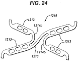
- FIG 24 provides greater detail of the "circular hinge region” 1218 that serves as a connection point between two strut pairs on adjacent windings of the helical section 1208.
- This hinge region 1218 includes several components, and provides a ductile region in between circumferentially adjacent struts 1213 that form a strut pair, while providing the necessary connectivity between longitudinally adjacent strut pairs by the flexible connector 1212.
- the longitudinally adjacent strut pairs and interconnecting flexible connector 1212 create regions known as "quad hinge regions”. These regions are comprised of four struts that are directly or indirectly connected through the circular hinges 1214b and flexible connectors 1212.
- FIG. 6B through 6M illustrated various connectors that can be use to connect adjacent strut pairs in the circular hinge region 1218. It is the number and spacing between circumferentially adjacent hinge regions 1218 that can be used to identify the structural feature 1220.
- the structural feature 1220 is located along the interior section 1208, functionally and structurally interrupting the helical pattern and effectively segregating the helical interior section 1208 into two separate subsections 1208A and 1208B.
- the structural feature 1220 includes a helical band element having a greater number of flexible connectors 1212, i.e. a greater number of circular hinge regions 1218, than the remainder of the interior helical section 1208. That is to say the number and spacing between hinge regions 1218 is greater in the structural feature 1220 region than in the remainder of the stent.
- the helical band element forming the structural feature 1220 having the denser flex connect geometry has been shaded.
- the first subsection 1208A is located between the proximal ring like section 1206 and the structural feature 1220.
- the second helical subsection 1208B is located between the distal ring-like end section 1207 and the structural feature 1220.
- the helical interior section 1208 may further include a central zone 1211 and proximal and distal transition zones 1209, 1210 respectively.
- the transition zones 1209, 1210 transition between the central zones 1211 and the proximal and distal ring-like end sections 1206, 1207 respectively.
- the central zone 1211 may include strings (collections of elements) formed from groups of contiguous strut members 1213 and hinge members 1214 organized to form a string pattern.
- contiguous strings have different string patterns and repeating strings, and the elements that make up the strings, are geometrically symmetric to form a repeating central pattern.
- the repeating central pattern consists of two different repeating strings.
- the central zone 1211 also includes the structural feature 1220 having the denser circular hinge regions 1218. The structural feature 1220 interrupts the repeating pattern in the central zone 1211, such that the repeating pattern of struts and hinges reside before and after the structural feature 1220.
- Figure 23 illustrates the strut strings that are part of the repeating pattern forming the central zone 1211 of the stent 1200 according to one example.
- the central zone 1211 generally has a pattern that includes a connector 1212 or hinge region 1218 attached at every fourth bend or undulation created by pairs of longitudinally adjacent struts 1213 connected by a hinge 1214 as the undulating pattern winds through the helical central zone 1211. That is to say a connector hinge 1214b is followed by three free hinges in the pattern.
- the structural feature 1220 shaded for clarity in Figures 22 and 23 , had a hinge region at every other undulation and the helical pattern winds through the central zone 1211.
- the repeating pattern of a connector hinge 1214b followed by three free hinges 1214a continues after the structural feature 1120 until the repeating pattern meets the distal transition zone 1210.
- the uninterrupted repeating pattern that forms the central zone 1211 is best illustrated by following the pattern starting at the distal end of the central zone 1211.
- the distal end of the central zone 1211 starts with a connector strut string.
- the illustrated connector strut string includes a connector hinge 1214b at its proximal and distal ends, and an arrangement of three long (three depot) struts 1213 connected by free hinges 1214a.
- the free strut string which follows the connector strut string when winding in a proximal direction, is attached on its distal end to the proximal end of the connector strut string.
- the illustrated free strut string includes a series of three long (three depot) struts 1213 interconnected by a free hinge 1214a.
- the three, three depot struts 1213 are connected on each end to a short two depot strut 1213 by free hinges 1214a.
- FIGS. 22 and 23 show the connectors 1212 in the structural feature 1220 all being oriented in the same direction relative to the longitudinal axis. That is, when moving in a distal to proximal direction, all the connectors 1212 connect from the lower end portion of a strut 1213 to the upper portion of the longitudinally adjacent strut 1213. An imaginary line drawn through each connector 1212 would form an acute angle with a line parallel to the longitudinal axis.
- FIGS 25 and 26 are plan views of a stent 1300 in a partially expanded condition according to one such embodiment of the present invention. Similar to stent 1200 previously disclosed, the stent 1300 architecture generally includes proximal and distal closed ring-like end sections 1306, 1307 along the proximal and distal ends 1304, 1305 respectively, and a substantially helical interior section 1308 there between. The stent 1300 includes a plurality of longitudinally oriented struts 1313 connected by a series of circumferentially oriented ductile hinges 1314.
- Circumferentially adjacent struts 1313 are connected at opposite ends by the hinges 1314 in a substantially S or Z shaped sinusoidal-like patter to form a band.
- Flexible connectors 1312 are distributed through the stent 1200 architecture for structural stability under a variety of loading conditions.
- the stent 1300 has a structural feature 1320, shaded for clarity, which includes additional connectors between adjacent helical windings in the central zone 1311.
- the band 1320 of connectors 1312 in stent 1300 have an alternating orientation. That is circumferentially adjacent connectors 1312 alternate between forming an acute angle with the longitudinal axis to obtuse angle with the longitudinal axis. Having connectors 1312 with opposite orientations provides addition shear strengthening when needed.
- FIGS. 27 and 28 are plan views of stent 1400 in a partially expanded condition according to one embodiment of the present invention that includes such feature.
- Figure 28 is an exploded plan view of stent 1400 illustrating the central and transition sections in each helical section.
- helical interior section 1408A includes a central zone 1411A and proximal and distal transition zones 1409A, 1410A respectively.
- the helical interior section 1418B includes a central zone 1411B and proximal and distal transition zones 1409B, 1410B respectively.
- the transition zones 1409A,B transitions the helical pattern between the central zones 1411A,B, respectively, and the proximal and distal ring-like end sections 1406, 1407 respectively.
- the transition zone 1410A,B transitions the helical pattern between the central zone 1411A,B, respectively, and the central ring-like section 1420.
- the central zones 1411A,B may include strings (collections of elements) formed from groups of contiguous strut members 1413 and hinge members 1414 organized to form a string pattern.
- contiguous strings have different string patterns and repeating strings, and the elements that make up the strings, are geometrically symmetric to form a repeating central pattern.
- the repeating central pattern consists of two different repeating strings.
- Figure 28 illustrates the strut strings that are part of the repeating pattern forming the central zones 1411A, 1411B of the stent 1400 according to one embodiment of the present invention.
- the uninterrupted repeating pattern that forms the central zone 1411 is best illustrated by following the pattern starting at the distal end of the central zone 1411B.
- the distal end of the central zone 1411B starts with a connector strut string.
- the illustrated connector strut string includes a connector hinge 1414b at its proximal and distal ends, and an arrangement of three long (three depot) struts 1413 connected by free hinges 1414a.
- the free strut string which follows the connector strut string when winding in a proximal direction, is attached on its distal end to the proximal end of the connector strut string.
- the illustrated free strut string includes a series of three long (three depot) struts 1413 interconnected by a free hinge 1414a.
- the three, three depot struts 1413 are connected on each end to a short two depot strut 1413 by free hinges 1414a.
- a similar pattern is found in central zone 1411A.
- the pattern of strut strings repeats throughout the central zones 1411A, 1411B.
- the closed ring forming structural feature 1420 provides a more rigid central area, which allows the stent to be more securely crimped to the expansion balloon. This will improve stent deployment.
- the design will also reduce the risk of forelenghtening during deployment, which will reduce unintended strain to the stent, create greater fracture resistance, and general aid in stent placement by maintaining the stent intended length.
Landscapes
- Health & Medical Sciences (AREA)
- Engineering & Computer Science (AREA)
- Biomedical Technology (AREA)
- Heart & Thoracic Surgery (AREA)
- Life Sciences & Earth Sciences (AREA)
- Cardiology (AREA)
- Oral & Maxillofacial Surgery (AREA)
- Transplantation (AREA)
- Veterinary Medicine (AREA)
- Vascular Medicine (AREA)
- Public Health (AREA)
- Animal Behavior & Ethology (AREA)
- General Health & Medical Sciences (AREA)
- Optics & Photonics (AREA)
- Physics & Mathematics (AREA)
- Media Introduction/Drainage Providing Device (AREA)
- Prostheses (AREA)
Description
- The present invention relates to tissue-supporting medical devices and drug delivery systems, and more particularly to expandable devices that are implanted within a body lumen of a living animal or human to support the organ, maintain patency and/or deliver drugs or agents.
- In the past, permanent or biodegradable devices have been developed for implantation within a body passageway to maintain patency of the passageway and/or locally deliver drug or agent. These devices are typically introduced percutaneously, and transported transluminally until positioned at a desired location. These devices are then expanded either mechanically, such as by the expansion of a mandrel or balloon positioned inside the device, or expand themselves by releasing stored energy upon actuation within the body. Once expanded within the lumen, these devices, typically referred to as stents, become encapsulated within the body tissue and remain a permanent implant.
- Known stent designs include monofilament wire coil stents (
U.S. Pat. No. 4,969,458 ); welded metal cages (U.S. Pat. Nos. 4,733,665 and4,776,337 ); and, most prominently, thin-walled metal cylinders with axial slots formed around the circumference (U.S. Pat. Nos. 4,733,665 ,4,739,762 , and4,776,337 ). Known construction materials for use in stents include polymers, organic fabrics and biocompatible metals, such as, stainless steel, gold, silver, tantalum, titanium, cobalt chromium and shape memory alloys such as Nitinol. -
U.S. Pat. Nos. 4,733,665 ,4,739,762 , and4,776,337 disclose expandable and deformable interluminal vascular grafts in the form of thin-walled tubular members with axial slots allowing the members to be expanded radially outwardly into contact with a body passageway. After insertion, the tubular members are mechanically expanded beyond their elastic limit and thus permanently fixed within the body. The force required to expand these tubular stents is proportional to the thickness of the wall material in a radial direction. To keep expansion forces within acceptable levels for use within the body (e.g., 507 - 1013 kPa (5-10 atm)), these designs must use very thin-walled materials (e.g., stainless steel tubing with 0.0635 mm (0.0025 inch) thick walls). However, materials this thin are not visible on conventional fluoroscopic and x-ray equipment and it is therefore difficult to place the stents accurately or to find and retrieve stents that subsequently become dislodged and lost in the circulatory system. - Further, many of these thin-walled tubular stent designs employ networks of long, slender struts whose width in a circumferential direction is two or more times greater than their thickness in a radial direction. When expanded, these struts are frequently unstable, that is, they display a tendency to buckle, with individual struts twisting out of plane. Excessive protrusion of these twisted struts into the bloodstream has been observed to increase turbulence, and thus encourage thrombosis. Additional procedures have often been required to attempt to correct this problem of buckled struts. For example, after initial stent implantation is determined to have caused buckling of struts, a second, highpressure balloon (e.g., 1.2 to 1.8 MPa (12 to 18 atm)) would be used to attempt to drive the twisted struts further into the lumen wall. These secondary procedures can be dangerous to the patient due to the risk of collateral damage to the lumen wall.
- In addition, many of the known stents display a large elastic recovery, known in the field as "recoil," after expansion inside a lumen. Large recoil necessitates over-expansion of the stent during implantation to achieve the desired final diameter. Over-expansion is potentially destructive to the lumen tissue. Known stents of the type described above experience recoil of up to about 6 to 12% from maximum expansion.
- Large recoil also makes it very difficult to securely crimp most known stents onto delivery catheter balloons. As a result, slippage of stents on balloons during interlumenal transportation, final positioning, and implantation has been an ongoing problem. Many ancillary stent securing devices and techniques have been advanced to attempt to compensate for this basic design problem. Some of the stent securing devices include collars and sleeves used to secure the stent onto the balloon.
- Another problem with known stent designs is non-uniformity in the geometry of the expanded stent. Non-uniform expansion can lead to non-uniform coverage of the lumen wall creating gaps in coverage and inadequate lumen support. Further, over expansion in some regions or cells of the stent can lead to excessive material strain and even failure of stent features. This problem is potentially worse in low expansion force stents having smaller feature widths and thicknesses in which manufacturing variations become proportionately more significant. In addition, a typical delivery catheter for use in expanding a stent includes a balloon folded into a compact shape for catheter insertion. The balloon is expanded by fluid pressure to unfold the balloon and deploy the stent. This process of unfolding the balloon causes uneven stresses to be applied to the stent during expansion of the balloon due to the folds causing the problem non-uniform stent expansion.
- It is desirable to provide flexibility in stents to facilitate introduction of the stent into vessels that are difficult to reach. Often, however, characteristics of the stent that provide longitudinal flexibility, which is desirable when introducing the stent into the vessel, can be disadvantageous in terms of keeping the stent in an expanded condition. For example, stents formed from interconnected rings with closed cell structures or generally diamond-shaped cells are typically less flexible than stents formed from one or more helices, but are usually more uniformly and consistently expandable than helical stents. It is desirable to provide a stent with substantial flexibility that is adapted to be expanded in a uniform and consistent fashion.
- In
WO 03/015664 -
US 2007/0005126 A1 discloses a stent comprising at least one segment, wherein the segment comprises a first tubular closed ring section, a second tubular closed ring section, a first generally helical section having a first end and a second end, and a second generally helical section having a first end and a second end. The first ends of the first and second generally helical sections extend from the first tubular closed ring section and the second ends extend from the second tubular closed ring section. The first and second generally helical sections both extend in the same direction about the longitudinal axis of the stent. -
WO 2008/049045 A2 discloses a helical stent including at least one helical winding. Each helical winding includes a plurality of alternating long struts and short struts, ends of at least some of the long struts being joined to an end of an adjacent short strut by a flexible hinge arrangement, the struts being substantially rigid. The stent also includes at least one interconnection member connecting a hinge arrangement on one turn of the at least one winding with a hinge arrangement on an adjacent turn of the at least one winding. Fewer than all hinge arrangements on the at least one helical winding are connected to other hinge arrangements by an interconnection member. - The present invention relates to tissue-supporting medical devices and drug delivery systems, and more particularly to expandable, devices that are implanted within a body lumen of a living animal or human to support the organ, maintain patency and/or deliver drugs or agents.
- Embodiments that are not encompassed in the appended claims are examples useful for understanding the invention.
- In accordance with an embodiment of the invention, there is provided a tubular flexible stent according to claim 1.
-
-
Figure 1A is a perspective view of a flexible stent in the expanded (deployed) state. -
Figure 1B is a perspective view of a flexible stent in the crimped state -
Figure 1C is a perspective view of a flexible stent in the "as cut" (manufactured) state.Figure 2 is a plan view of a flexible stent. -
Figure 3 is an exploded plan view of the flexible stent ofFigure 2 . -
Figure 4A is a close-up plan view of a strut from a flexible stent. -
Figure 4B is a close-up plan view of a strut from a flexible stent. -
Figure 4C is a close-up plan view of a strut from a flexible stent. -
Figure 4D is a close-up plan view of an organically optimized strut from a flexible stent. -
Figure 5A is a close-up plan view of a ductile hinge from a flexible stent. -
Figure 5B is a close-up plan view of a ductile hinge from a flexible stent. -
Figure 6A is a close-up plan view of a circular hinge region from a flexible stent. -
Figure 6B is a close-up plan view of a circular hinge region from a flexible stent. -
Figure 6C is a close-up plan view of a circular hinge region from a flexible stent. -
Figure 6D is a close-up plan view of a circular hinge region from a flexible stent. -
Figure 6E is a close-up plan view of a circular hinge region from a flexible stent. -
Figure 6F is a close-up plan view of a circular hinge region from a flexible stent. -
Figure 6G is a close-up plan view of a circular hinge region from a flexible stent. -
Figure 6H is a close-up plan view of a circular hinge region from a flexible stent. - Figure 61 is a close-up plan view of a circular hinge region from a flexible stent.
-
Figure 6J is a close-up plan view of a circular hinge region from a flexible stent. - Figure 6K is a close-up plan view of a circular hinge region from a flexible stent.
-
Figure 6L is a close-up plan view of a circular hinge region from a flexible stent. -
Figure 6M is a close-up plan view of a circular hinge region from a flexible stent. -
Figure 7 is a close-up plan view of an index hinge from a flexible stent. -
Figure 8 is a close-up plan view of the central zone depicted inFigure 3 to illustrate the incident angle of the helical band (wrap). -
Figure 9A is a close-up plan view of a connector strut string that is part of the repeating pattern that forms the central zone of the flexible stent illustrated inFigure 2 . -
Figure 9B is a close-up plan view of a free strut string that is part of the repeating pattern that forms the central zone of the flexible stent illustrated inFigure 2 . -
Figure 10 is a plan view of a flexible stent. -
Figure 11 is an exploded plan view of the flexible stent ofFigure 10 . -
Figure 12 is a plan view of a flexible stent. -
Figure 13 is an exploded plan view of the flexible stent ofFigure 12 . -
Figure 14 is a plan view of a flexible stent. -
Figure 15 is an exploded plan view of the flexible stent ofFigure 14 . -
Figure 16 is a close-up plan view of the free strut string and the connector strut string that are part of the repeating pattern that form the central zone of the flexible stent illustrated inFigure 14 . -
Figure 17 is a close-up plan view of the free strut string and the connector strut string that are part of the repeating pattern that form the central zone of the flexible stent illustrated inFigure 12 . -
Figure 18 is a close-up plan view of the free strut string and the connector strut string that are part of the repeating pattern that form the central zone of the flexible stent illustrated inFigure 10 . -
Figure 19 is a plan view of a flexible stent without depots. -
Figure 20 is a plan view of a flexible stent. -
Figure 21 is an exploded plan view of the flexible stent ofFigure 20 . -
Figure 22 is a plan view of a flexible stent. -
Figure 23 is an exploded plan view of the flexible stent ofFigure 22 . -
Figure 24 is a close-up plan view of a circular hinge region from a flexible stent according to the embodiment of the present invention. -
Figure 25 is a plan view of a flexible stent. -
Figure 26 is an exploded plan view of the flexible stent ofFigure 25 . -
Figure 27 is a plan view of a flexible stent according to the embodiment of the present invention. -
Figure 28 is an exploded plan view of the flexible stent ofFigure 27 . - The stent of the present invention is very flexible and deliverable, while still providing sufficient radial strength to maintain vessel patency. The stent can be formed in any suitable manner, such as by laser cutting a tube made from a suitable material, including cobalt chromium alloys, stainless steel alloys or nickel titanium alloys. Although coronary flexible stents of the present invention are disclosed to illustrate one embodiment of the present invention, one of ordinary skill in the art would understand that the disclosed invention can be equally applied to other locations and lumens in the body, such as, for example, vascular, non-vascular and peripheral vessels, ducts, and the like.
- In accordance with one aspect of the present invention, the flexible stent is designed to be crimped down to a reduced diameter and percutaneously delivered through a body lumen to a target site by a delivery catheter. The target site may be, for example, a cardiac artery. Once deployed the flexible stent functions to maintain vessel patency and, if desired, deliver controlled amounts of drug or agent.
- Perspective views of a
flexible stent 100 in the expanded (deployed), crimped, and "as cut" or manufactured state according to one embodiment of the present invention are illustrated inFigures 1A ,1B and1C respectively. Thestent 100 has an "as cut" diameter when first manufactured of D3, as illustrated inFigure 1C . Thestent 100 is crimped down to a first diameter D1, illustrated inFigure 1B , for insertion into a patient and navigation through the vessels, and a second diameter D2, illustrated inFigure 1A , for deployment into the target area of a vessel, with the second diameter being greater than the first diameter. - The
flexible stent 100 is cylindrical with a tubular configuration of structural elements having luminal and abluminal surfaces, 101, 102 respectively, and thickness (wall thickness) "T" there between. The cylindrical shape of the stent defines alongitudinal axis 103 and has proximal anddistal ends portions - The terms proximal and distal are typically used to connote a direction or position relative to a human body. For example, the proximal end of a bone may be used to reference the end of the bone that is closer to the center of the body. Conversely, the term distal can be used to refer to the end of the bone farthest from the body. In the vasculature, proximal and distal are sometimes used to refer to the flow of blood to the heart, or away from the heart, respectively. Since the flexible stent described in this invention can be used in many different body lumens, including both the arterial and venous system, the use of the terms proximal and distal in this application are used to describe relative position in relation to the direction of delivery. For example, the use of the term distal end portion in the present application describes the end portion of the stent first introduced into the vasculature and farthest from the entry point into the body relative to the delivery path. Conversely, the use of the term proximal end portion is used to describe the back end portion of the stent that is closest to the entry point into the body relative to the delivery path.
-
Figures 2 and3 are plan views of thestent 100 in a partially expanded condition according to one embodiment of the present invention. As used herein, the term plan view is understood to be a two-dimensional (2-D) view of a stent that has been cut along the longitudinal axis and laid out flat, such that the bottom edge could be wrapped around a cylinder and connected to the top edge. - The
stent 100 architecture generally includes ring-like end sections interior section 108 there between. The helicalinterior section 108 further includes acentral zone 111 and proximal anddistal transition zones transition zones central zone 111 and the proximal and distal ring-like end sections Figure 3 is an exploded plan view of thestent 100 illustrating the different sections and zones. - The
stent 100 includes a plurality of longitudinally orientedstruts 113 connected by a series of circumferentially oriented ductile hinges 114. Circumferentiallyadjacent struts 113 are connected at opposite ends by thehinges 114 in a substantially S or Z shaped sinusoidal-like pattern to form a band.Flexible connectors 112 are distributed throughout thestent 100 architecture for structural stability under a variety of loading conditions. The stent design illustrated inFigures 1 through 3 have a flexible connector geometry, however, a wide variety of connector geometries are contemplated. See generallyFigures 6B through 6H . - The region in the
stent 100 where the interiorhelical section 108 is first connected to the ring-like end sections hinge 114 at that location is referred to as an "anchor hinge". This "take off' point may vary based on design constraints. Additionally, the incident angle, strut thickness, strut width, hinge width, hinge length, depot position and size, and connection length may vary based on optimization and design constraints. - As used herein the terms longitudinally, circumferentially and radially oriented are known to denote a particular direction relative to the
stent 100 and thelongitudinal axis 103. A longitudinally oriented member is directed, end to end (along its axis), generally in the direction of thelongitudinal axis 103. It is obvious after reviewing the figures that the longitudinal direction of thestrut 113 is closer to being parallel to the longitudinal axis when thestent 100 is in the crimped state as illustrated inFigure 1B , then when thestent 100 is in the expanded, deployed state as illustrated inFigure 1A . Regardless, in each case, thestrut 113 is considered to be longitudinally oriented as the axis of thestrut 113 is substantially oriented in the same direction as the longitudinal axis. A circumferentially oriented member, such ashinge 114, is directed substantially along the circumference of thetubular stent 100. Similarly, a radial direction or radially oriented is along a radius that extends generally from the longitudinal axis outward to the circumference of thetubular stent 100 in cross-section. -
Figures 4A, 4B and4C illustratetypical struts 113 according to various examples. Eachstrut 113 is a substantially rectangular shaped member having longitudinally extendinglong sides 115 and circumferentially extendingshort sides 116. Opposinglong sides 115 andshort sides 116 may be substantially parallel to one another forming a near perfect rectangular as depicted by thestrut 113 illustrated inFigure 4A , or may be canted or angled to form atapered strut 113 as depicted by thestrut 113 illustrated inFigure 4B . As can be seen infigures 4A and 4B , thehinges 114 attached to thestrut 113 along theshort sides 116 of the strut, however the width of the strut (length of the short side 116) is greater than the width of thehinge 114 in a preferred embodiment of the invention. As illustrated inFigure 4B , theflexible connectors 112 connect to thestruts 113 along theshort sides 116 of thestruts 113, but do not connect to thehinges 114. -
Figure 4C represents aunique strut 113 that may be found in some embodiments of thestent 100 design. Thestrut 113 depicted inFigure 4C is characterized by two connection points to circular hinges 114 (as hereinafter described) and two connection points toflexible connectors 112. Thisstrut 113 is widest at the proximal and distal ends (at the connection points of thehinges 114 and flexible connectors 112) and tapers to its minimum width near the mid-point in thelongitudinal strut 113 length. That is to say the length of theshort side 116 of thestrut 113 depicted inFigure 4C is greater than the width near the longitudinal center point of thestrut 113. - The
struts 113 may have one ormore depots 117 for containing at least one agent. Thedepots 117 may be any form of recess, channel, hole or cavity capable of holding an agent, but are preferably through holes precisionly formed through thestent 100. In a preferred embodiment, the through hole passes through the strut from the luminal to abluminal surface. This preferred configuration may allow an agent or agents to be delivered both in a radially inward and outward direction along the luminal and abluminal sides of thestent 100. In addition, thedepots 117 may be filled with a polymer inlay, either alone or containing one or more agents in solution or otherwise.Various depots 117 in the same stent may be filled with the same or different agents, and may have the same or different concentrations of agents. Anyindividual depot 117 may be filed with one or multiple agents, and the agents may be separated by a barrier layer. The barrier layer may be position in various configurations in thedepot 117 as need to separate the agents. In a preferred embodiment, the barrier layer is oriented parallel to the luminal stent surface. - The
struts 113 may have symmetricallysized depots 117 as illustrated inFigures 4A-4C , or may include organically optimizeddepots 117 as illustrated inFigures 4D . Organically optimizeddepots 117 are designed to maximize thedepot 117 volume for any givenstrut 113 size, while reducing the stress state of the entire feature through the addition or removal of material critical to maintaining structural integrity uponstent 100 expansion. - As the term is used herein, the agent can be any therapeutic or pharmaceutic agent or drug, including the following: antiproliferative/antimitotic agents including natural products such as vinca alkaloids (i.e. vinblastine, vincristine, and vinorelbine), paclitaxel, epidipodophyllotoxins (i.e. etoposide, teniposide), antibiotics (dactinomycin (actinomycin D) daunorubicin, doxorubicin and idarubicin), anthracyclines, mitoxantrone, bleomycins, plicamycin (mithramycin) and mitomycin, enzymes (L-asparaginase which systemically metabolizes L-asparagine and deprives cells which don't have the capacity to synthesize their own asparagine; antiproliferative/antimitotic alkylating agents such as nitrogen mustards (mechlorethamine, cyclophosphamide and analogs, melphalan, chlorambucil), ethylenimines and methylmelamines (hexamethylmelamine and thiotepa), alkyl sulfonates-busulfan, nitrosoureas (carmustine (BCNU) and analogs, streptozocin), trazenes--dacarbazinine (DTIC); antiproliferative/antimitotic antimetabolites such as folic acid analogs (methotrexate), pyrimidine analogs (fluorouracil, floxuridine, and cytarabine), purine analogs and related inhibitors (mercaptopurine, thioguanine, pentostatin and 2-chlorodeoxyadenosine {cladribine}); platinum coordination complexes (cisplatin, carboplatin), procarbazine, hydroxyurea, mitotane, aminoglutethimide; hormones (i.e.estrogen); Anticoagulants (heparin, synthetic heparin salts and other inhibitors of thrombin); fibrinolytic agents (such as tissue plasminogen activator, streptokinase and urokinase), aspirin, dipyridamole, ticlopidine, clopidogrel, abciximab; antimigratory; antisecretory (breveldin); antiinflammatory: such as adrenocortical steroids (cortisol, cortisone, fludrocortisone, prednisone, prednisolone, 6α-methylprednisolone, triamcinolone, betamethasone, and dexamethasone), non-steroidal agents (salicylic acid derivatives i.e. aspirin; para-aminophenol derivatives i. e. acetominophen; Indole and indene acetic acids (indomethacin, sulindac, and etodalac), heteroaryl acetic acids (tolmetin, diclofenac, and ketorolac), arylpropionic acids (ibuprofen and derivatives), anthranilic acids (mefenamic acid, and meclofenamic acid), enolic acids (piroxicam, tenoxicam, phenylbutazone, and oxyphenthatrazone), nabumetone, gold compounds (auranofin, aurothioglucose, gold sodium thiomalate); immunosuppressive: (cyclosporine, tacrolimus (FK-506), sirolimus (rapamycin), azathioprine, mycophenolate mofetil); angiogenic: vascular endothelial growth factor (VEGF), fibroblast growth factor (FGF); nitric oxide donors; anti-sense oligo nucleotides and combinations thereof.
- One or more agents may be distributed in one or more of the
depots 117, along at least a portion of the luminal orabluminal stent 100 surfaces, or any combination of depots and/or stent surfaces. In a preferred example, the agent is distributed in thedepots 117 only, such that the exposed agent surface area is limited to the cross-sectional area of the depot opening in thestent 100 surface (luminal, abluminal or both). This design allows for agent delivery from thestent 100 having a surface area upon insertion into the patient that is substantially bare metal. In a preferred embodiment, the exposed bare metal surface area of thestent 100 is between 40 and 95 percent upon insertion of thestent 100 into a patient, and is most preferably approximately 75 percent bare metal upon insertion of thestent 100 into a patient. That is, the surface area of thestent 100 is approximately 25 percent agent and approximately 75 percent bare metal. As the agent is released, thestent 100 becomes a purely bare metal stent. - In a preferred example, the
depots 117 are distributed nearly uniformly throughout the strut pattern to provide a consistent agent dosage per unit surface area of the deployedstent 100 independent of the diameter or length of the stent used. Thestruts 113 may be of varying lengths, incident angle, depot configuration, and widths as needed to meet the product design. - Ductile hinges 114 are used as the connection element between two circumferentially
adjacent struts 113. There are two types of ductile hinges 114 found instent 100.Figures 5A and 5B illustrate the two typical ductile hinges found in one embodiment of the present invention.Figure 5A represents a single "free hinge" 114a that connects two circumferentiallyadjacent struts 113. In a preferred embodiment, thisfree hinge 114a is "C" shaped and is substantially symmetric about reference line "A" drawn though the apex point on the curved section.Figure 5B represents aductile hinge 114b that connects two circumferentiallyadjacent struts 113, where one of the struts is further connected to aflexible connector 112. Thisductile hinge 114b is more circular in shape than the "C" shapedfree hinge 114a disclosed inFigure 5A , and is sometimes referred hereto as a "circular hinge" 14b. Althoughfree hinges 114a and connector hinges 114b are identified separately here, they are sometimes generally both referred to as ductile hinges 114. The regions surrounding the circular hinge 14b is referred to as a circular hinge region. While theflexible connector 112 and circularductile hinge 114b both connect to the sameshort side 116 of thestrut 113 in the circular hinge region, they are not connected to one another. -
Figure 6A provides greater detail of the "circular hinge region" 118 that serves as a connection point between two strut pairs on adjacent windings of thehelical section 108. Thishinge region 118 includes several components, and provides a ductile region in between circumferentiallyadjacent struts 113 that form a strut pair, while providing the necessary connectivity between longitudinally adjacent strut pairs by theflexible connector 112. When combined, the longitudinally adjacent strut pairs and interconnectingflexible connector 112 create regions known as "quad hinge regions". These regions are comprised of four struts that are directly or indirectly connected through the circular hinges 114b andflexible connectors 112. The incident angle, hinge 114b width, degree of taper, length, and hole pattern are subject to change based on the stents intended design, the location of the feature and stent performance optimization.Figures 6B through 6M illustratedvarious connectors 112 that can be use to connect adjacent strut pairs in thecircular hinge region 118. -
Figure 7 illustrates another key stent attribute important during the manufacturing process of thestent 100. The encircledductile hinge 114 is known as the "index hinge". This "index hinge" is characterized bylonger strut 113 lengths, which causes the ductile hinge or strut 113 head to protrude beyond the plane of thestrut 113 heads on the remaining struts within the sinusoidal end ring. For ease of illustration, reference line A has been drawn perpendicular to thelongitudinal axis 103 and tangent to the curved surfaces of both thehinges 114 above and below the index hinge. Reference line B has been drawn perpendicular to thelongitudinal axis 103 and tangent to the curved surface of thehinge 114 representing the index hinge. The distance between reference lines A and B along the longitudinal axis is the offset provided by the index. This offset serves as a reference point to help determine the orientation of thestent 100. The "index hinge" may occur at any location along the proximal and distal ring-like end sections - Generally speaking, the ductile hinges 114 are deformable elements that are substantially thinner in width than the surrounding struts 113. This allows the ductile hinges 114 to sustain plastic deformation while still remaining flexible in the deformed state. The
struts 113 are therefore much stiffer than the ductile hinges 114, and thus do not experience any plastic deformation during stent expansion. Thestruts 113 essentially rotate as rigid bodies, while the ductile hinges 114 are designed to the bear the plastic strains associated with stent expansion. As a result, thedepots 117 in thestruts 113 are shielded from undue stress during expansion that may cause damage or dislodgement of the agents and/or polymer inlays. Thedepots 117 are ideally in a stress-free state throughout the stent deployment process. - In a preferred example, the ductile hinges 114 are optimized, through the use of width tapering, such that they offer sufficient radial stiffness to the
stent 100 while simultaneously ensuring that peak plastic strains at full expansion do not exceed the strain carrying capability of the material. This width tapering is optimized, for eachhinge 114 type, to achieve a smooth and uniform distribution of plastic strains along the length of theductile hinge 114. By smoothing the strain distribution and thus eliminating strain concentrations in theductile hinge 114, the width, and thereby stiffness, is maximized. Maximizing the stiffness of theductile hinge 114 is advantageous in providing radial stiffness and fatigue durability for thestent 100. - In general the width of the tapered
ductile hinge 114 gradually increases while approaching the root of thehinge 114, where thehinge 114 meets an abrupt transition into the wider strut 113 (or stiffer structure). This prevents plastic strains from concentrating at the roots of the hinges since the tapered hinge root is stiffer and therefore distributes plastic strain to the central portion of thehinge 114. The central portion of theductile hinge 114, which encompasses the apex of the curve, generally has a uniform width. - Turning again to
Figures 2 and3 , the ring-like end sections strut members 113 connected at opposite ends by a plurality of circumferentially oriented ductile hinges 114 in a substantially sinusoidal S or Z shaped pattern so as to form the band into an endless ring. In the illustrated embodiment, theend sections struts 113 of varying length as needed optimize the stent design and provide the necessary geometry for the connection at the anchor point where the interiorhelical section 108 is first connected to the ring-like end sections - Between the ring-
like end sections helical section 108 of thestent 100, where the band of sinusoidally arranged struts 113 and hinges 114 follow a helical path. The helical band of theinterior section 108 is achieved by arranging thestruts 113 in a repeating pattern of alternating short and long lengths. The helicalinterior section 108 may be further divided into proximal anddistal transition zone central zone 111. - The
central zone 111 comprises strings (collections of elements) formed from groups ofcontiguous strut members 113 and hingemembers 114 organized to form a string pattern. In one embodiment of the invention, contiguous strings have different string patterns and repeating strings are geometrically symmetric to form a repeating central pattern. In a preferred example, the repeating central pattern consists of two different repeating strings. Thecentral zone 111 therefore has a constant pitch and incident angle. - As used herein the term pitch is understood to mean the number of sinusoidal turns over a given area. This is similar nomenclature to the diametral pitch of a gear. The greater the pitch, the greater the number of sinusoidal turns, i.e. the greater number of
struts 113 andductile hinges 114, will be found per wrap as the sinusoidal band winds about thelongitudinal axis 103. This creates a very dense pattern ofstruts 113 and hinges 114. Conversely, the smaller the pitch, the smaller number of sinusoidal turns, and thus the smaller number ofstruts 113 and hinges 114 will be found per wrap as the sinusoidal band winds about thelongitudinal axis 103. The term incident angle refers specifically to the helical winding section of thestent 100 and is understood to mean the angle at which the sinusoidal band makes (wraps) with the longitudinal axis. -
Figure 8 is a close up 2 dimensional view of thecentral zone 111 depicted inFigure 3 . A first reference line "A" has been drawn parallel to thelongitudinal axis 103. A second reference line "B" has been drawn to represent the direction of the sinusoidal band. The incident angle (α) is the angle between reference line A and reference line B. -
Figures 9A and 9B illustrate the two strut strings that are part of the repeating pattern that form thecentral zone 111 of thestent 100 according to one embodiment of the present invention. Referring toFigure 3 ,8 ,9A and 9B , thecentral zone 111 starts at the proximal end of thedistal transition zone 110 with afree strut string 119 illustrated inFigure 9B . The illustratedfree strut string 119 includes a long threedepot strut 113 connected on each end to a short twodepot strut 113 by afree hinge 114a. Thefree strut string 119 is attached on its proximal end to the distal end of aconnector strut string 120. Theconnector strut string 120 includes aconnector hinge 114b at its proximal and distal ends, and an alternating arrangement of three long (three depot) struts 113 and two short (two depot) struts 113 connected byfree hinges 114a. This pattern of alternatingfree strut strings 119 andconnector strut strings 120 continue until thecentral zone 111 meets theproximal transition zone 109. The embodiment illustrated inFigure 3 has a central zone that includes fivefree strut strings 119 and four connector strut strings 120. The length of thestent 100 can be changed by adding or shortening thecentral zone 111, i.e. by adding or removingfree strut strings 119 orconnector strut strings 120 as necessary to maintain the repeating pattern, while maintaining the proximal anddistal transition zones like end section - The proximal and
distal transition zones distal transition zones central zone 111 and the proximal and distal ring-like end sections distal transition zones like end section - The
stent 100 designs depicted in the aforementioned figures are known as an open cell design, meaning that connectors between longitudinally adjacent windings of sinusoidal elements occur only intermittently through the structure rather than spanning every longitudinallyadjacent hinge 114 orstrut 113. A design in which every longitudinally adjacent hinge or strut is connected is known as a closed cell design. An open-celled architecture is generally more flexible than a closed-cell architecture. - As previously described, the general architecture of the
stent 100 includes a helicalinterior section 108 with ring -like end sections connectors 112 distributed through the architecture for structural stability under a variety of loading conditions. The helicalinterior section 108 may be further separated into acentral zone 111 having a constant pitch and incident angle, and proximal anddistal transition zones -
Figures 10 through 15 illustrate various examples of the stent designs for different diametrically size stents.Figures 10 ,12 and14 are two-dimensional plan views, similar toFigure 2 , illustratingstents Figures 11 ,13 and15 are exploded plan views, similar toFigure 3 , of thestents stent 100, and it is understood that the description of elements related tostent 100 applies equally to like elements instents - Each stent pattern design is customized to target optimal results based on the treatment of the stent's intended target vessel.
Figures 10 and11 represents one embodiment of astent 200 intended for extra small diameter target vessel lesions. The extra small diameter stent family has been optimized for very small vessel diameters via several design features, and is meant to be fabricated from a smaller diameter tubing material. - The current example for an extra small stent includes sinusoidal proximal and distal ring-
like end sections like end sections like end sections helical section 208 of thestent 200, where the sinusoidal arrangement ofstruts 213 and hinges 214 follow a helical path. The helical path of theinterior section 208 is achieved by arranging thestruts 213 in a repeating pattern of alternating short and long lengths to form a band. There are ninestruts 213 per winding in each the interior bands. The fewer number of struts allows for increased stent performance while maintaining critical processing parameters. The helicalinterior section 208 may be further divided into proximal anddistal transition zones central zone 211 as illustrated inFigure 11 . - The
central zone 211 consists of repeating strut strings, or collections of struts, which are geometrically symmetric to form a repeating pattern in the band. Thecentral zone 211 therefore has a constant pitch and incident angle. The repeating interior pattern is comprised of two 3-strut patterns that alternate to form the 9-strut repeating interior pattern. -
Figure 18 illustrates the twostrut strings central zone 211 of thestent 200 according to one example. - Referring to
Figure 10 ,11 and18 , thecentral zone 211 starts at the distal end of theproximal transition zone 209 with afree strut string 219 illustrated inFigure 18 . The illustratedfree strut string 219 includes a long (four depot)strut 213 connected on each end to a short (two depot)strut 213 by afree hinge 214a. Thefree strut string 219 is attached on its distal end to the proximal end of aconnector strut string 220. Theconnector strut string 220 includes aconnector hinge 214b at its proximal and distal ends, and an alternating arrangement of two long (four depot) struts 213 and one short (two depot)strut 213 connected byfree hinges 214a. This pattern of alternatingfree strut strings 219 andconnector strut strings 220 continue until thecentral zone 211 meets thedistal transition zone 210. The embodiment illustrated inFigures 10 and11 have a central zone that includes sixfree strut strings 219 and six connector strut strings 220. - The current example for a medium sized stent includes sinusoidal proximal and distal ring-
like end sections strut 313 end rings. Between the ring-like end sections helical section 308 of thestent 300, where the sinusoidal arrangement ofstruts 313 and hinges 314 in the band follow a helical path. The helical path of theinterior section 308 is achieved by arranging thestruts 313 in a repeating pattern of alternating short and long lengths to form the band. There are thirteenstruts 313 per band winding in the interiorhelical section 308. The increased number of struts allows for increased stent performance while maintaining critical processing parameters. The helicalinterior section 308 may be further divided into proximal anddistal transition zones central zone 311 as illustrated inFigure 13 . - The
central zone 311 consists of repeating strut strings, or collections of struts, which are geometrically symmetric to form a repeating pattern. Thecentral zone 311 therefore has a constant pitch and incident angle. The repeating interior pattern is comprised of one 3-strut pattern and one 5-strut pattern that alternate to form the 13-strut repeating interior pattern. -
Figure 17 illustrates the twostrut strings central zone 311 of thestent 300 according to one embodiment of the present invention. Referring toFigure 12 ,13 and17 , thecentral zone 311 starts at the distal end of the proximal transition zone with aconnector strut string 320 illustrated inFigure 17 . The illustratedconnector strut string 320 includes aconnector hinge 314b at its proximal and distal ends, and an arrangement of three long (three depot) struts 313 connected byfree hinges 314a. Thefree strut string 319 is attached on its proximal end to the distal end of theconnector strut string 320. The illustratedfree strut string 319 includes a series of three long (three depot) struts 313 interconnected by afree hinge 314a. The three, three depot struts 313 are connected on each end to a short twodepot strut 313 byfree hinges 314a. The pattern of alternating connector strut strings 320 andfree strut strings 319 continue until thecentral zone 311 meets thedistal transition zone 310. The example illustrated inFigures 12 and13 has a central zone that includes three connector strut strings 320 and two free strut strings 319. The length of thestent 300 can be changed by adding or shortening thecentral zone 311, i.e. by adding or removing connector strut strings 320 orfree strut strings 319 as necessary to maintain the repeating pattern, while maintaining the proximal anddistal transition zones like end section -
Figures 14 and15 represents one example of astent 400 intended for a large diameter target vessel lesions. The large diameter stent family has been optimized for larger vessels via several design features. Like previous designs, the current embodiment contains sinusoidal proximal and distal ring-like end sections struts 413 in saidend sections end sections distal transition zones Figure 15 . -
Figure 16 illustrates the two strut strings that are part of the repeating pattern from thecentral zone 411 of thestent 400 according to one embodiment of the present invention. Referring toFigure 14 ,15 and16 , thecentral zone 411 starts at the proximal end of thedistal transition zone 410 with afree strut string 419 illustrated inFigure 16 . The illustratedfree strut string 419 includes an alternating arrangement of short (three depot) struts 413 and long (four depot) struts (413) interconnected on each end by afree hinge 414a. Thefree strut string 419 is attached on its proximal end to the distal end of aconnector strut string 420. Theconnector strut string 420 is threestruts 413 long, and includes aconnector hinge 414b at its proximal and distal ends. The three struts in theconnector string 420 include an alternating arrangement of long (four depot) struts 413 and a short (three depot)strut 413 connected byfree hinges 414a. This pattern of alternatingfree strut strings 419 andconnector strut strings 420 continue until thecentral zone 411 meets theproximal transition zone 409. The embodiment illustrated inFigure 15 has a central zone that includes threefree strut strings 419 and two connector strut strings 420. - The present disclosure also contemplates the use of solid struts in similar strut/hinge orientations as those disclosed in
figures 2 ,10 ,12 , and14 .Figure 19 illustrates astent 500 having similar design architecture without depots along thestruts 513.Stent 500 can be used as a bare metal stent or can be partially or completely coated with an agent and/or appropriate carrier as is known in the art. -
Stents 100 through 500 previously depicted and described have helicalinterior sections interior section interior section - The central zones comprise strings (collections of elements) formed from groups of contiguous strut members and hinge members organized to form a string pattern. In one example, contiguous strings have different string patterns and repeating strings are geometrically symmetric to form a repeating central pattern. In a preferred example, the repeating central pattern consists of two different repeating strings. The central zone therefore may have a constant pitch and incident angle. Complimentary elements forming the strings and string patterns, i.e. struts and hinges in like strings, are generally uniform in size and shape.
- Another stent design may have one or more structural features along the intermediate section of the helical interior section to effectively interrupt the repeating central pattern in the interior section, particularly the central zone, to create a central zone with two separate helical subsections of repeating patterns, one before and one after the structural feature.
- The structural feature may add more structure to the stent while retraining overall stent flexibility. When a balloon is used to mechanically expand the stent, the feature may also provide additional securement of the stent on the balloon, and reduce the risk of fore lengthening - the unintentional axial stretching the open cell design as a result of deployment. The condition is particularly prevalent if the balloon moves or pulls one end of the stent.
- The structural feature may be centered along the helical section length, effectively bisecting the intermediate section into two equal subsections. Centering the structural feature offers the opportunity for symmetry of the stent, simplifying design and modeling, and allowing stent properties to remain more uniform. However, the structural feature does not need to be centrally located with the intermediate helical section, and this design should not unnecessarily limit the scope of this invention.
- Various examples having a structural feature are illustrated in the following figures. Like reference numerals are used to indicate similar features and elements between the featured stent and
stents 100 through 500 previously described. For example, strut 113 instent 100 is similar to strut 1113 instent 1100. -
Figures 20 and21 are plan views of astent 1100 in a partially expanded condition according to one example. The stent architecture generally includes proximal and distal closed ring-like end sections distal ends interior section 1108 there between. Thestent 1100 includes a plurality of longitudinally orientedstruts 1113 connected by a series of circumferentially oriented ductile hinges 1114. Circumferentiallyadjacent struts 1113 are connected at opposite ends by thehinges 1114 in a substantially S or Z shaped sinusoidal-like patter to form a band.Flexible connectors 1112 are distributed through thestent 1100 architecture for structural stability under a variety of loading conditions. The stent design illustrated inFigures 20 and21 has a flexible connector geometry, however a wide variety of connectors geometries are contemplated. See generallyFigures 6B through 6H . - A
structural feature 1120 is located along theinterior section 1108, functionally interrupting the helical pattern and effectively segregating the helicalinterior section 1108 into twoseparate subsections structural feature 1120 includes ahelical band element 1120 having wider elements at coincident points along the element profile than the remainder of thehelical section 1108. A coincident point would be the same relative point on a similar element. For example, the strut width measurement at the midpoint along the longitudinal length of a 3 depot strut in thehelical band element 1120 would be wider than the strut width measurement at the midpoint along the longitudinal length of a 3 depot strut that is not in thehelical band element 1120. In particular, the illustrated example shows ahelical band element 1120 havingwider hinges 1114 and struts 1113, however, ahelical band 1120 having onlywider hinges 1114 or struts 1113 is also contemplated by the present invention. Thishelical band 1120 is stiffer, changing the expansion and flexibility characteristics of the stent. The width, size and shape of the members can be altered to "tune" the stent and achieve the desired characteristics. - The
first subsection 1108A is located between the proximal ring likesection 1106 and the widenedhelical band element 1120. The secondhelical subsection 1108B is located between the distal ring-like end section 1107 and the widenedhelical band element 1120. The helicalinterior section 1108 may further include acentral zone 1111 and proximal anddistal transition zones transition zones central zones 1111 and the proximal and distal ring-like end sections - The
central zone 1111 may include strings (collections of elements) formed from groups ofcontiguous strut members 1113 andhinge members 1114 organized to form a string pattern. In one example, contiguous strings have different string patterns and repeating strings, and the elements that make up the string, are geometrically symmetric to form a repeating central pattern. In a preferred embodiment of the invention, the repeating central pattern consists of two different repeating strings. Thecentral zone 1111 also includes the widenedhelical band element 1120. Thestructural feature 1120 interrupts the repeating pattern in thecentral zone 1111, while the remaining repeating pattern of struts and hinges continues before and after the widenedhelical band element 1120. -
Figure 21 illustrates the two strut strings that are part of the repeating pattern forming thecentral zone 1111 of thestent 1100 according to one embodiment of the present invention. Thecentral zone 1111 starts at the distal end of theproximal transition zone 1109 with a connector strut string. The illustrated connector strut string includes a connector hinge 1114b at its proximal and distal ends, and an arrangement of three long (three depot) struts 1113 connected by free hinges 1114a. The free strut string, which follows the connector strut string, is attached on its proximal end to the distal end of the connector strut string. The illustrated free strut string includes a series of three long (three depot) struts 1113 interconnected by a free hinge 1114a. The three, threedepot struts 1113 are connected on each end to a short twodepot strut 1113 by free hinges 1114a. The pattern of alternating connector strut strings and free strut strings continue until thestring pattern 1111 meets the structural feature 1120 - in the illustrated embodiment the widenedhelical band element 1120. As previously described, the elements forming the strings and string patterns, i.e. struts and hinges, are generally uniform in size and shape to complimentary elements in like strings and string patterns. However, thestructural feature 1120 illustrated inFigures 20 and21 breaks this pattern. While thestructural feature 1120 in the illustrated embodiment does maintain the same strut strings and pattern as the remainder of thecentral zone 1111, thestructural feature 1120 is formed from struts and hinges that are wider than the preceding and following strings. As such, the elements that form thestructural feature 1120 are not of the same size and shape as the elements that form the remainder of thecentral zone 1111. The repeating pattern continues after the structural feature 1120 (widened helical band) until the repeating pattern meets thedistal transition zone 1110. - Another example of a structural feature that interrupts the repeating pattern in the central zone includes a section having additional connectors between adjacent helical windings.
Figures 22 and23 are plan views of astent 1200 in a partially expanded condition according to one such embodiment of the present invention. Similar to stents previously disclosed, thestent 1200 architecture generally includes proximal and distal closed ring-like end sections distal ends interior section 1208 there between. Thestent 1200 includes a plurality of longitudinally orientedstruts 1213 connected by a series of circumferentially oriented ductile hinges 1214. Circumferentiallyadjacent struts 1213 are connected at opposite ends by thehinges 1214 in a substantially S or Z shaped sinusoidal-like patter to form a band.Flexible connectors 1212 are distributed through thestent 1200 architecture for structural stability under a variety of loading conditions. To clearly illustrate thestructural feature 1220 havingadditional connectors 1212 reference is made to the connection regions and ductile hinges. - Similar to the stents previously disclosed, there are two types of
ductile hinges 1214 found instent 1200. As described earlier,Figures 5A and 5B illustrate the two typical ductile hinges.Figure 5A represents a single "free hinge" 114a, akin to free hinge 1214a of the present example, which connects two circumferentiallyadjacent struts 113. In a preferred example, thisfree hinge 114a is "C" shaped and is substantially symmetric about reference line "A" drawn though the apex point on the curved section.Figure 5B represents aductile hinge 114b, akin to hinge 1214b of the present example, that connects two circumferentiallyadjacent struts 113, where one of the struts is further connected to aflexible connector 112. Thisductile hinge 114b is more circular in shape than the "C" shapedfree hinge 114a disclosed inFigure 5A , and is sometimes referred hereto as a "circular hinge" 114b. Although free hinges 1214a and connector hinges 1214b are identified separately here, they are sometimes generally both referred to as ductile hinges 1214. The regions surrounding thecircular hinge 1214b is referred to as a circular hinge region. While theflexible connector 1212 and circularductile hinge 1214b both connect to the same short side of thestrut 1213 in the circular hinge region, they are not connected to one another. -
Figure 24 provides greater detail of the "circular hinge region" 1218 that serves as a connection point between two strut pairs on adjacent windings of thehelical section 1208. Thishinge region 1218 includes several components, and provides a ductile region in between circumferentiallyadjacent struts 1213 that form a strut pair, while providing the necessary connectivity between longitudinally adjacent strut pairs by theflexible connector 1212. When combined, the longitudinally adjacent strut pairs and interconnectingflexible connector 1212 create regions known as "quad hinge regions". These regions are comprised of four struts that are directly or indirectly connected through the circular hinges 1214b andflexible connectors 1212. The incident angle, hinge 1214b width, degree of taper, length, and hole pattern are subject to change based on the stents intended design, the location of the feature and stent performance optimization.Figures 6B through 6M illustrated various connectors that can be use to connect adjacent strut pairs in thecircular hinge region 1218. It is the number and spacing between circumferentiallyadjacent hinge regions 1218 that can be used to identify thestructural feature 1220. - The
structural feature 1220 is located along theinterior section 1208, functionally and structurally interrupting the helical pattern and effectively segregating the helicalinterior section 1208 into twoseparate subsections structural feature 1220 includes a helical band element having a greater number offlexible connectors 1212, i.e. a greater number ofcircular hinge regions 1218, than the remainder of the interiorhelical section 1208. That is to say the number and spacing betweenhinge regions 1218 is greater in thestructural feature 1220 region than in the remainder of the stent. For clarity, the helical band element forming thestructural feature 1220 having the denser flex connect geometry has been shaded. In particular, the illustrated embodiment shows astructural feature 1220 havingflex connectors 1212 connected betweenhinge regions 1218 at every other circumferentially adjacent strut pair. Theadditional flex connectors 1212 make thestructural feature 1220 stiffer than the remainder of thestent 1200, changing the expansion and flexibility characteristics of the stent. The number and spacing of theflexible connectors 1212 can be altered to "tune" the stent and achieve the desired characteristics. For example, the stent could also have astructural element 1220 where theflex connectors 1212 are connected between every longitudinally adjacent strut pair. - Referring again to
Figures 22 and23 , thefirst subsection 1208A is located between the proximal ring likesection 1206 and thestructural feature 1220. The secondhelical subsection 1208B is located between the distal ring-like end section 1207 and thestructural feature 1220. The helicalinterior section 1208 may further include acentral zone 1211 and proximal anddistal transition zones transition zones central zones 1211 and the proximal and distal ring-like end sections - The
central zone 1211 may include strings (collections of elements) formed from groups ofcontiguous strut members 1213 andhinge members 1214 organized to form a string pattern. In one example, contiguous strings have different string patterns and repeating strings, and the elements that make up the strings, are geometrically symmetric to form a repeating central pattern. In a preferred example, the repeating central pattern consists of two different repeating strings. Thecentral zone 1211 also includes thestructural feature 1220 having the densercircular hinge regions 1218. Thestructural feature 1220 interrupts the repeating pattern in thecentral zone 1211, such that the repeating pattern of struts and hinges reside before and after thestructural feature 1220. -
Figure 23 illustrates the strut strings that are part of the repeating pattern forming thecentral zone 1211 of thestent 1200 according to one example. Thecentral zone 1211 generally has a pattern that includes aconnector 1212 or hingeregion 1218 attached at every fourth bend or undulation created by pairs of longitudinallyadjacent struts 1213 connected by ahinge 1214 as the undulating pattern winds through the helicalcentral zone 1211. That is to say aconnector hinge 1214b is followed by three free hinges in the pattern. However, thestructural feature 1220, shaded for clarity inFigures 22 and23 , had a hinge region at every other undulation and the helical pattern winds through thecentral zone 1211. The repeating pattern of aconnector hinge 1214b followed by three free hinges 1214a continues after thestructural feature 1120 until the repeating pattern meets thedistal transition zone 1210. The uninterrupted repeating pattern that forms thecentral zone 1211 is best illustrated by following the pattern starting at the distal end of thecentral zone 1211. The distal end of thecentral zone 1211 starts with a connector strut string. The illustrated connector strut string includes aconnector hinge 1214b at its proximal and distal ends, and an arrangement of three long (three depot) struts 1213 connected by free hinges 1214a. The free strut string, which follows the connector strut string when winding in a proximal direction, is attached on its distal end to the proximal end of the connector strut string. The illustrated free strut string includes a series of three long (three depot) struts 1213 interconnected by a free hinge 1214a. The three, threedepot struts 1213 are connected on each end to a short twodepot strut 1213 by free hinges 1214a. - The example illustrated in
Figures 22 and23 show theconnectors 1212 in thestructural feature 1220 all being oriented in the same direction relative to the longitudinal axis. That is, when moving in a distal to proximal direction, all theconnectors 1212 connect from the lower end portion of astrut 1213 to the upper portion of the longitudinallyadjacent strut 1213. An imaginary line drawn through eachconnector 1212 would form an acute angle with a line parallel to the longitudinal axis. - Another example contemplates alternating the direction of the
connectors 1212 in some pattern.Figures 25 and26 are plan views of astent 1300 in a partially expanded condition according to one such embodiment of the present invention. Similar tostent 1200 previously disclosed, thestent 1300 architecture generally includes proximal and distal closed ring-like end sections distal ends interior section 1308 there between. Thestent 1300 includes a plurality of longitudinally orientedstruts 1313 connected by a series of circumferentially oriented ductile hinges 1314. Circumferentiallyadjacent struts 1313 are connected at opposite ends by thehinges 1314 in a substantially S or Z shaped sinusoidal-like patter to form a band.Flexible connectors 1312 are distributed through thestent 1200 architecture for structural stability under a variety of loading conditions. - In addition, the
stent 1300 has astructural feature 1320, shaded for clarity, which includes additional connectors between adjacent helical windings in thecentral zone 1311. However, unlike the dense band ofconnectors 1212 formingstructural feature 1220 instent 1200, where allconnectors 1212 are oriented in the same direction, theband 1320 ofconnectors 1312 instent 1300 have an alternating orientation. That is circumferentiallyadjacent connectors 1312 alternate between forming an acute angle with the longitudinal axis to obtuse angle with the longitudinal axis. Havingconnectors 1312 with opposite orientations provides addition shear strengthening when needed. - An inventive embodiment of a structural feature that interrupts the repeating pattern in the central zone includes a structural feature in the form of a ring-like central section, similar to the ring-like end sections previously described.
Figures 27 and28 are plan views ofstent 1400 in a partially expanded condition according to one embodiment of the present invention that includes such feature. - The
stent 1400 architecture generally includes proximal and distal ring-like end sections distal ends central section 1420 located there between. The ring-like sections - The
stent 1400 further includes at least two helical sections between the ring-like sections. In the illustrated embodiment, a firsthelical section 1408A is located between the proximal ring likeend section 1406 and the central ring-like section 1420. A secondhelical section 1408B is located between the distal ring-like end section 1407 and the central ring-like section 1420. The helicalinterior sections -
Figure 28 is an exploded plan view ofstent 1400 illustrating the central and transition sections in each helical section. Particularly, helicalinterior section 1408A includes acentral zone 1411A and proximal anddistal transition zones central zone 1411B and proximal anddistal transition zones transition zones 1409A,B transitions the helical pattern between thecentral zones 1411A,B, respectively, and the proximal and distal ring-like end sections transition zone 1410A,B transitions the helical pattern between thecentral zone 1411A,B, respectively, and the central ring-like section 1420. - The
stent 1400 includes a plurality of longitudinally orientedstruts 1413 connected by a series of circumferentially oriented ductile hinges 1414. Circumferentiallyadjacent struts 1413 are connected at opposite ends by thehinges 1414 in a substantially S or Z shaped sinusoidal-like pattern to form a band. The band forming the ring-like end sections structural feature 1420 are closed rings. The bands forming the centralhelical sections 1408A,B are wound about the longitudinal axis in a spiral or helical fashion.Flexible connectors 1412 are distributed throughout thestent 1400 architecture for structural stability under a variety of loading conditions. The stent design illustrated inFigures 27 and28 have a flexible connector geometry, however a wide variety of connector geometries are contemplated. See generallyFigures 6B through 6H . - The
central zones 1411A,B may include strings (collections of elements) formed from groups ofcontiguous strut members 1413 andhinge members 1414 organized to form a string pattern. In one embodiment of the invention, contiguous strings have different string patterns and repeating strings, and the elements that make up the strings, are geometrically symmetric to form a repeating central pattern. In a preferred embodiment of the invention, the repeating central pattern consists of two different repeating strings. -
Figure 28 illustrates the strut strings that are part of the repeating pattern forming thecentral zones stent 1400 according to one embodiment of the present invention. The uninterrupted repeating pattern that forms the central zone 1411 is best illustrated by following the pattern starting at the distal end of thecentral zone 1411B. The distal end of thecentral zone 1411B starts with a connector strut string. The illustrated connector strut string includes a connector hinge 1414b at its proximal and distal ends, and an arrangement of three long (three depot) struts 1413 connected by free hinges 1414a. The free strut string, which follows the connector strut string when winding in a proximal direction, is attached on its distal end to the proximal end of the connector strut string. The illustrated free strut string includes a series of three long (three depot) struts 1413 interconnected by a free hinge 1414a. The three, threedepot struts 1413 are connected on each end to a short twodepot strut 1413 by free hinges 1414a. A similar pattern is found incentral zone 1411A. The pattern of strut strings repeats throughout thecentral zones - The closed ring forming
structural feature 1420 provides a more rigid central area, which allows the stent to be more securely crimped to the expansion balloon. This will improve stent deployment. The design will also reduce the risk of forelenghtening during deployment, which will reduce unintended strain to the stent, create greater fracture resistance, and general aid in stent placement by maintaining the stent intended length.
Claims (22)
- A tubular flexible stent (1400) having proximal and distal end portions (1404, 1405) and a cylindrical shape, with luminal and abluminal surfaces and a thickness there between, the cylindrical shape defining a longitudinal axis, the tubular flexible stent comprising:a proximal helical section (1408A), a distal helical section (1408B) and an intermediate ring section (1420) there between, each of the proximal and distal helical sections having a plurality of longitudinally oriented strut members (1413) and a plurality of circumferentially oriented ductile hinge members (1414) connecting circumferentially adjacent strut members (1413) to form a band, the ductile hinge members (1414) being substantially thinner in width than the surrounding strut members (1413) and the band being wrapped about the longitudinal axis in a substantially helical manner to form a plurality of helical windings,at least one flexible connector member (1412) extending between longitudinally adjacent helical windings of the band and serving to connect two strut pairs on longitudinally adjacent windings, the at least one flexible connector member connecting a circumferentially adjacent strut member (1413) of a first strut pair on a helical winding to a circumferentially adjacent strut member (1413) of a second strut pair on an adjacent helical winding, wherein each strut member (1413) has opposing longitudinally oriented long sides and opposing circumferentially oriented short sides, each hinge member (1414) being connected to the circumferentially adjacent strut member (1413) along the short side of the strut member, wherein each at least one of the flexible connector member (1412) is attached to the short sides of longitudinally adjacent strut members, said connector member (1412) not being attached to longitudinally adjacent hinge members (1414), ,the intermediate ring section (1420) comprised of a plurality of longitudinally oriented strut members (1413) and a plurality of circumferentially oriented ductile hinge members (1414) connecting circumferentially adjacent strut members (1413) to form an endless ring, the intermediate ring section (1420) being attached to the distal end of the proximal helical section and the proximal end of the distal helical section by at least one flexible connector member (1412).
- The flexible stent (1400) of claim 1 wherein the proximal and distal helical sections (1408A, 14088) each comprise strings formed from groups of contiguous strut members and hinge members organized to form a geometrically symmetric string pattern, and wherein contiguous strings along the band have different string patterns.
- The flexible stent (1400) of claim 1 wherein each strut member (1413) has a substantially rectangular shape.
- The flexible stent (1400) of Claim 1 wherein the hinge and strut members (1414, 1413) forming the band are arranged in a substantially S or Z shaped sinusoidal-like pattern.
- The flexible stent (1400) of Claim 1 wherein the width of each strut member (1413) is greater than the width of each hinge member (1414) attached to said strut member.
- The flexible stent (1400) of Claim 1 wherein the width of at least one strut member (1413) tapers along its longitudinal length.
- The flexible stent (1400) of Claim 6 wherein the strut member width is greatest at one of the short sides and smallest at the opposing short side.
- The flexible stent (1400) of Claim 6 wherein the strut member width is smallest at a point along the strut member length that is between the opposing short sides.
- The flexible stent (1400) of Claim 1 wherein at least one of the strut members (1413) has at least one depot (117) for loading at least one agent therein.
- The flexible stent (1400) of Claim 9 wherein the at least one depot (117) extends through the strut member (1413) so as to define a through opening.
- The flexible stent (1400) of Claim 9 wherein the at least one depot (117) has a depth less than the thickness of said at least one strut member (1413) so as to define a recess.
- The flexible stent (1400) of Claim 9 wherein the agent has an abluminal exposed agent surface area equal to the total cross-sectional area of the depot openings in the abluminal surface of the flexible stent, and the flexible stent has an abluminal bare surface area excluding the cross-sectional area of the depot openings in the abluminal surface, the abluminal exposed agent surface area and the abluminal bare surface area equaling the flexible stent total abluminal surface area, wherein the abluminal bare surface area is between 50 percent and 90 percent of the flexible stent total abluminal surface area.
- The flexible stent (1400) of Claim 12 wherein the abluminal bare surface area is approximately 75 percent of the flexible stent total abluminal surface area.
- The flexible stent (1400) of Claim 10 wherein the at least one deport comprises a plurality of depots and at least two depots of the plurality of depots contain at least one different agent, or contain different concentrations of the same agent.
- The flexible stent (1400) of Claim 9 wherein the agent has an exposed agent surface area equal to the total cross-sectional area of the depot openings in the surfaces of the flexible stent, and the flexible stent has a bare surface area excluding the cross-sectional area of the depot openings in the surfaces, the exposed agent surface area and the bare surface area equaling the flexible stent total surface area, wherein the bare surface area is between 40 percent and 90 percent of the flexible stent total surface area.
- The flexible stent (1400) of Claim 1 wherein each of the proximal and distal helical sections (1408A,B) comprise a proximal transition zone (1409A,B), a distal transition zone (1410A,B), and a central zone (1411A,B) there between, each having a pitch and an incident angle, wherein the pitch and incident angle of the proximal and distal transition zones are different than the central zone.
- The flexible stent (1400) of Claim 16 wherein the central zone (1411A,B) has a constant pitch and incident angle.
- The flexible stent (1400) of Claim 16 wherein the proximal transition zone and distal transition zone (1409A,B, 1410A,B) each have a variable pitch and incident angle.
- The flexible stent (1400) of Claim 16 wherein the central zone (1411A,B) comprises strings formed from groups of contiguous strut members and hinge members organized to form a string pattern, wherein contiguous strings along the band have different string patterns.
- The flexible stent (1400) of Claim 19 wherein the central section comprises repeating strings that are symmetric to form a repeating central pattern.
- The flexible stent (1400) of Claim 20 where the repeating central pattern consists of two different repeating strings.
- The flexible stent (1400) of claim 1 further comprising:a proximal end ring (1406) comprised of a plurality of longitudinally oriented strut members and a plurality of circumferentially oriented hinge members connecting circumferentially adjacent strut members to form an endless ring, the proximal end ring being attached to the proximal end of the helical section by at least one of the connector members; anda distal end ring (1407) comprised of a plurality of longitudinally oriented strut members and a plurality of circumferentially oriented hinge members connecting circumferentially adjacent strut members to form an endless ring, the distal end ring being attached to the distal end of the helical section by at least one of the connector members.
Applications Claiming Priority (2)
| Application Number | Priority Date | Filing Date | Title |
|---|---|---|---|
| US36996210P | 2010-08-02 | 2010-08-02 | |
| PCT/US2011/046299 WO2012018840A1 (en) | 2010-08-02 | 2011-08-02 | Flexible helical stent having intermediated non-helical region |
Publications (2)
| Publication Number | Publication Date |
|---|---|
| EP2600803A1 EP2600803A1 (en) | 2013-06-12 |
| EP2600803B1 true EP2600803B1 (en) | 2022-05-18 |
Family
ID=44533145
Family Applications (1)
| Application Number | Title | Priority Date | Filing Date |
|---|---|---|---|
| EP11743732.7A Active EP2600803B1 (en) | 2010-08-02 | 2011-08-02 | Flexible helical stent having intermediated non-helical region |
Country Status (11)
| Country | Link |
|---|---|
| US (1) | US10231855B2 (en) |
| EP (1) | EP2600803B1 (en) |
| JP (1) | JP5914479B2 (en) |
| KR (2) | KR20130096716A (en) |
| CN (1) | CN103118639B (en) |
| AU (1) | AU2011285808B2 (en) |
| BR (1) | BR112013002720A2 (en) |
| CA (1) | CA2807025C (en) |
| IL (1) | IL224233A (en) |
| MX (1) | MX2013001443A (en) |
| WO (1) | WO2012018840A1 (en) |
Families Citing this family (2)
| Publication number | Priority date | Publication date | Assignee | Title |
|---|---|---|---|---|
| CA2807119C (en) * | 2010-08-02 | 2017-08-01 | Cordis Corporation | Flexible helical stent having different helical regions |
| WO2025086189A1 (en) * | 2023-10-26 | 2025-05-01 | Covidien Lp | Stent with struts defining circumferentially offset apices |
Family Cites Families (61)
| Publication number | Priority date | Publication date | Assignee | Title |
|---|---|---|---|---|
| US5102417A (en) | 1985-11-07 | 1992-04-07 | Expandable Grafts Partnership | Expandable intraluminal graft, and method and apparatus for implanting an expandable intraluminal graft |
| US4733665C2 (en) | 1985-11-07 | 2002-01-29 | Expandable Grafts Partnership | Expandable intraluminal graft and method and apparatus for implanting an expandable intraluminal graft |
| SE453258B (en) | 1986-04-21 | 1988-01-25 | Medinvent Sa | ELASTIC, SELF-EXPANDING PROTEST AND PROCEDURE FOR ITS MANUFACTURING |
| US4969458A (en) | 1987-07-06 | 1990-11-13 | Medtronic, Inc. | Intracoronary stent and method of simultaneous angioplasty and stent implant |
| US5507767A (en) | 1992-01-15 | 1996-04-16 | Cook Incorporated | Spiral stent |
| US5913897A (en) | 1993-09-16 | 1999-06-22 | Cordis Corporation | Endoprosthesis having multiple bridging junctions and procedure |
| EP0688545B1 (en) | 1994-06-17 | 2002-09-18 | Terumo Kabushiki Kaisha | Method for manufacturing an indwelling stent |
| BE1009278A3 (en) | 1995-04-12 | 1997-01-07 | Corvita Europ | Guardian self-expandable medical device introduced in cavite body, and medical device with a stake as. |
| JP4636634B2 (en) | 1996-04-26 | 2011-02-23 | ボストン サイエンティフィック サイムド,インコーポレイテッド | Intravascular stent |
| US20040106985A1 (en) | 1996-04-26 | 2004-06-03 | Jang G. David | Intravascular stent |
| US20020058990A1 (en) | 2000-09-23 | 2002-05-16 | Jang G. David | Intravascular stent consists of stairstep expansion strut pairs and double stairstep diagonal connecting struts contralaterally extended from expansion struts |
| US6783543B2 (en) | 2000-06-05 | 2004-08-31 | Scimed Life Systems, Inc. | Intravascular stent with increasing coating retaining capacity |
| US5922021A (en) | 1996-04-26 | 1999-07-13 | Jang; G. David | Intravascular stent |
| US6488706B1 (en) | 1996-05-08 | 2002-12-03 | Carag Ag | Device for plugging an opening such as in a wall of a hollow or tubular organ |
| US7070590B1 (en) | 1996-07-02 | 2006-07-04 | Massachusetts Institute Of Technology | Microchip drug delivery devices |
| US20040267350A1 (en) | 2002-10-30 | 2004-12-30 | Roubin Gary S. | Non-foreshortening intraluminal prosthesis |
| US5827321A (en) | 1997-02-07 | 1998-10-27 | Cornerstone Devices, Inc. | Non-Foreshortening intraluminal prosthesis |
| US5810872A (en) * | 1997-03-14 | 1998-09-22 | Kanesaka; Nozomu | Flexible stent |
| US6033433A (en) | 1997-04-25 | 2000-03-07 | Scimed Life Systems, Inc. | Stent configurations including spirals |
| US7329277B2 (en) | 1997-06-13 | 2008-02-12 | Orbusneich Medical, Inc. | Stent having helical elements |
| US6059822A (en) | 1997-08-22 | 2000-05-09 | Uni-Cath Inc. | Stent with different mesh patterns |
| US6190406B1 (en) * | 1998-01-09 | 2001-02-20 | Nitinal Development Corporation | Intravascular stent having tapered struts |
| US5938697A (en) | 1998-03-04 | 1999-08-17 | Scimed Life Systems, Inc. | Stent having variable properties |
| US7208010B2 (en) * | 2000-10-16 | 2007-04-24 | Conor Medsystems, Inc. | Expandable medical device for delivery of beneficial agent |
| DE19829701C1 (en) * | 1998-07-03 | 2000-03-16 | Heraeus Gmbh W C | Radially expandable support device IV |
| US5911754A (en) | 1998-07-24 | 1999-06-15 | Uni-Cath Inc. | Flexible stent with effective strut and connector patterns |
| US6193744B1 (en) | 1998-09-10 | 2001-02-27 | Scimed Life Systems, Inc. | Stent configurations |
| US6042597A (en) | 1998-10-23 | 2000-03-28 | Scimed Life Systems, Inc. | Helical stent design |
| US6355059B1 (en) * | 1998-12-03 | 2002-03-12 | Medinol, Ltd. | Serpentine coiled ladder stent |
| US6096072A (en) | 1999-01-26 | 2000-08-01 | Uni-Cath Inc. | Self-exchange stent with effective supporting ability |
| US6730116B1 (en) * | 1999-04-16 | 2004-05-04 | Medtronic, Inc. | Medical device for intraluminal endovascular stenting |
| US6245101B1 (en) | 1999-05-03 | 2001-06-12 | William J. Drasler | Intravascular hinge stent |
| FR2793673B1 (en) * | 1999-05-18 | 2001-10-12 | Jean Marie Lefebvre | TUBULAR STENT TYPE WITH LOW CRUSHING RESISTANCE |
| US6569193B1 (en) | 1999-07-22 | 2003-05-27 | Advanced Cardiovascular Systems, Inc. | Tapered self-expanding stent |
| CA2392006C (en) | 1999-11-17 | 2011-03-15 | Microchips, Inc. | Microfabricated devices for the delivery of molecules into a carrier fluid |
| US6352552B1 (en) * | 2000-05-02 | 2002-03-05 | Scion Cardio-Vascular, Inc. | Stent |
| US6423091B1 (en) | 2000-05-16 | 2002-07-23 | Cordis Corporation | Helical stent having flat ends |
| AU2001261801A1 (en) | 2000-05-22 | 2001-12-03 | Orbus Medical Technologies Inc. | Self-expanding stent |
| EP1296615B2 (en) | 2000-06-05 | 2012-06-13 | Boston Scientific Limited | INTRAVASCULAR STENT WITH improved COATING RETAINING CAPACITY |
| US6652576B1 (en) | 2000-06-07 | 2003-11-25 | Advanced Cardiovascular Systems, Inc. | Variable stiffness stent |
| US7766956B2 (en) | 2000-09-22 | 2010-08-03 | Boston Scientific Scimed, Inc. | Intravascular stent and assembly |
| EP2311412B2 (en) | 2000-12-11 | 2017-10-11 | OrbusNeich Medical, Inc. | Stent having helical elements |
| US6969402B2 (en) | 2002-07-26 | 2005-11-29 | Syntheon, Llc | Helical stent having flexible transition zone |
| US6878162B2 (en) | 2002-08-30 | 2005-04-12 | Edwards Lifesciences Ag | Helical stent having improved flexibility and expandability |
| DE10261822A1 (en) * | 2002-12-20 | 2004-07-01 | Biotronik Meß- und Therapiegeräte GmbH & Co. Ingenieurbüro Berlin | Helix bridge connection |
| US20050033410A1 (en) | 2002-12-24 | 2005-02-10 | Novostent Corporation | Vascular prothesis having flexible configuration |
| US20070239251A1 (en) * | 2002-12-31 | 2007-10-11 | Abbott Cardiovascular Systems Inc. | Flexible stent |
| US7163555B2 (en) | 2003-04-08 | 2007-01-16 | Medtronic Vascular, Inc. | Drug-eluting stent for controlled drug delivery |
| US7169179B2 (en) | 2003-06-05 | 2007-01-30 | Conor Medsystems, Inc. | Drug delivery device and method for bi-directional drug delivery |
| US7637939B2 (en) * | 2005-06-30 | 2009-12-29 | Boston Scientific Scimed, Inc. | Hybrid stent |
| DE102006017873A1 (en) * | 2005-07-14 | 2007-01-25 | Qualimed Innovative Medizinprodukte Gmbh | Temporary stent |
| US8956400B2 (en) | 2005-10-14 | 2015-02-17 | Flexible Stenting Solutions, Inc. | Helical stent |
| GB0616999D0 (en) | 2006-08-29 | 2006-10-04 | Angiomed Ag | Annular mesh |
| US8545545B2 (en) * | 2006-10-18 | 2013-10-01 | Innovational Holdings Llc | Stent with flexible hinges |
| US20080097582A1 (en) * | 2006-10-18 | 2008-04-24 | Conor Medsystems, Inc. | Stent with flexible hinges |
| US8691321B2 (en) * | 2006-10-20 | 2014-04-08 | Orbusneich Medical, Inc. | Bioabsorbable polymeric composition and medical device background |
| EP2086599A4 (en) * | 2006-10-20 | 2012-11-28 | Orbusneich Medical Inc | Bioabsorbable medical device with coating |
| US7972373B2 (en) | 2007-12-19 | 2011-07-05 | Advanced Technologies And Regenerative Medicine, Llc | Balloon expandable bioabsorbable stent with a single stress concentration region interconnecting adjacent struts |
| US7722661B2 (en) * | 2007-12-19 | 2010-05-25 | Boston Scientific Scimed, Inc. | Stent |
| US8597343B2 (en) * | 2009-09-18 | 2013-12-03 | Medtronic Vascular, Inc. | Stent with constant stiffness along the length of the stent |
| US8801775B2 (en) * | 2010-04-27 | 2014-08-12 | Medtronic Vascular, Inc. | Helical stent with opposing and/or alternating pitch angles |
-
2011
- 2011-08-02 EP EP11743732.7A patent/EP2600803B1/en active Active
- 2011-08-02 CN CN201180047911.4A patent/CN103118639B/en not_active Expired - Fee Related
- 2011-08-02 MX MX2013001443A patent/MX2013001443A/en active IP Right Grant
- 2011-08-02 CA CA2807025A patent/CA2807025C/en active Active
- 2011-08-02 BR BR112013002720A patent/BR112013002720A2/en not_active Application Discontinuation
- 2011-08-02 JP JP2013523283A patent/JP5914479B2/en active Active
- 2011-08-02 KR KR1020137005474A patent/KR20130096716A/en not_active Ceased
- 2011-08-02 WO PCT/US2011/046299 patent/WO2012018840A1/en not_active Ceased
- 2011-08-02 US US13/196,462 patent/US10231855B2/en active Active
- 2011-08-02 KR KR1020167022605A patent/KR101961531B1/en not_active Expired - Fee Related
- 2011-08-02 AU AU2011285808A patent/AU2011285808B2/en not_active Ceased
-
2013
- 2013-01-15 IL IL224233A patent/IL224233A/en active IP Right Grant
Also Published As
| Publication number | Publication date |
|---|---|
| EP2600803A1 (en) | 2013-06-12 |
| US20120029621A1 (en) | 2012-02-02 |
| CN103118639A (en) | 2013-05-22 |
| IL224233A (en) | 2017-01-31 |
| JP2013535290A (en) | 2013-09-12 |
| JP5914479B2 (en) | 2016-05-11 |
| KR101961531B1 (en) | 2019-07-17 |
| US10231855B2 (en) | 2019-03-19 |
| KR20130096716A (en) | 2013-08-30 |
| AU2011285808A1 (en) | 2013-02-07 |
| MX2013001443A (en) | 2013-03-12 |
| KR20160103150A (en) | 2016-08-31 |
| CN103118639B (en) | 2016-11-09 |
| BR112013002720A2 (en) | 2016-05-31 |
| WO2012018840A1 (en) | 2012-02-09 |
| CA2807025A1 (en) | 2012-02-09 |
| AU2011285808B2 (en) | 2015-04-30 |
| CA2807025C (en) | 2017-01-24 |
Similar Documents
| Publication | Publication Date | Title |
|---|---|---|
| EP2391312B1 (en) | Flexible stent design | |
| EP2600804B1 (en) | Flexible helical stent having different helical regions | |
| EP2600801B1 (en) | Flexible helical stent having intermediate structural feature | |
| EP2600802B1 (en) | Flexible helical stent having intermediate structural feature | |
| EP2600803B1 (en) | Flexible helical stent having intermediated non-helical region | |
| AU2014265075B2 (en) | Flexible helical stent having intermediate structural feature |
Legal Events
| Date | Code | Title | Description |
|---|---|---|---|
| PUAI | Public reference made under article 153(3) epc to a published international application that has entered the european phase |
Free format text: ORIGINAL CODE: 0009012 |
|
| 17P | Request for examination filed |
Effective date: 20130123 |
|
| AK | Designated contracting states |
Kind code of ref document: A1 Designated state(s): AL AT BE BG CH CY CZ DE DK EE ES FI FR GB GR HR HU IE IS IT LI LT LU LV MC MK MT NL NO PL PT RO RS SE SI SK SM TR |
|
| DAX | Request for extension of the european patent (deleted) | ||
| STAA | Information on the status of an ep patent application or granted ep patent |
Free format text: STATUS: EXAMINATION IS IN PROGRESS |
|
| 17Q | First examination report despatched |
Effective date: 20170719 |
|
| RAP1 | Party data changed (applicant data changed or rights of an application transferred) |
Owner name: CORDIS CORPORATION |
|
| RAP1 | Party data changed (applicant data changed or rights of an application transferred) |
Owner name: CARDINAL HEALTH SWITZERLAND 515 GMBH |
|
| RAP1 | Party data changed (applicant data changed or rights of an application transferred) |
Owner name: CARDINAL HEALTH 529, LLC |
|
| GRAP | Despatch of communication of intention to grant a patent |
Free format text: ORIGINAL CODE: EPIDOSNIGR1 |
|
| STAA | Information on the status of an ep patent application or granted ep patent |
Free format text: STATUS: GRANT OF PATENT IS INTENDED |
|
| INTG | Intention to grant announced |
Effective date: 20211202 |
|
| GRAS | Grant fee paid |
Free format text: ORIGINAL CODE: EPIDOSNIGR3 |
|
| GRAA | (expected) grant |
Free format text: ORIGINAL CODE: 0009210 |
|
| STAA | Information on the status of an ep patent application or granted ep patent |
Free format text: STATUS: THE PATENT HAS BEEN GRANTED |
|
| AK | Designated contracting states |
Kind code of ref document: B1 Designated state(s): AL AT BE BG CH CY CZ DE DK EE ES FI FR GB GR HR HU IE IS IT LI LT LU LV MC MK MT NL NO PL PT RO RS SE SI SK SM TR |
|
| REG | Reference to a national code |
Ref country code: GB Ref legal event code: FG4D |
|
| REG | Reference to a national code |
Ref country code: CH Ref legal event code: EP |
|
| REG | Reference to a national code |
Ref country code: IE Ref legal event code: FG4D |
|
| REG | Reference to a national code |
Ref country code: DE Ref legal event code: R096 Ref document number: 602011072909 Country of ref document: DE |
|
| REG | Reference to a national code |
Ref country code: AT Ref legal event code: REF Ref document number: 1492746 Country of ref document: AT Kind code of ref document: T Effective date: 20220615 |
|
| REG | Reference to a national code |
Ref country code: NL Ref legal event code: FP |
|
| REG | Reference to a national code |
Ref country code: LT Ref legal event code: MG9D |
|
| REG | Reference to a national code |
Ref country code: AT Ref legal event code: MK05 Ref document number: 1492746 Country of ref document: AT Kind code of ref document: T Effective date: 20220518 |
|
| PG25 | Lapsed in a contracting state [announced via postgrant information from national office to epo] |
Ref country code: SE Free format text: LAPSE BECAUSE OF FAILURE TO SUBMIT A TRANSLATION OF THE DESCRIPTION OR TO PAY THE FEE WITHIN THE PRESCRIBED TIME-LIMIT Effective date: 20220518 Ref country code: PT Free format text: LAPSE BECAUSE OF FAILURE TO SUBMIT A TRANSLATION OF THE DESCRIPTION OR TO PAY THE FEE WITHIN THE PRESCRIBED TIME-LIMIT Effective date: 20220919 Ref country code: NO Free format text: LAPSE BECAUSE OF FAILURE TO SUBMIT A TRANSLATION OF THE DESCRIPTION OR TO PAY THE FEE WITHIN THE PRESCRIBED TIME-LIMIT Effective date: 20220818 Ref country code: LT Free format text: LAPSE BECAUSE OF FAILURE TO SUBMIT A TRANSLATION OF THE DESCRIPTION OR TO PAY THE FEE WITHIN THE PRESCRIBED TIME-LIMIT Effective date: 20220518 Ref country code: HR Free format text: LAPSE BECAUSE OF FAILURE TO SUBMIT A TRANSLATION OF THE DESCRIPTION OR TO PAY THE FEE WITHIN THE PRESCRIBED TIME-LIMIT Effective date: 20220518 Ref country code: GR Free format text: LAPSE BECAUSE OF FAILURE TO SUBMIT A TRANSLATION OF THE DESCRIPTION OR TO PAY THE FEE WITHIN THE PRESCRIBED TIME-LIMIT Effective date: 20220819 Ref country code: FI Free format text: LAPSE BECAUSE OF FAILURE TO SUBMIT A TRANSLATION OF THE DESCRIPTION OR TO PAY THE FEE WITHIN THE PRESCRIBED TIME-LIMIT Effective date: 20220518 Ref country code: ES Free format text: LAPSE BECAUSE OF FAILURE TO SUBMIT A TRANSLATION OF THE DESCRIPTION OR TO PAY THE FEE WITHIN THE PRESCRIBED TIME-LIMIT Effective date: 20220518 Ref country code: BG Free format text: LAPSE BECAUSE OF FAILURE TO SUBMIT A TRANSLATION OF THE DESCRIPTION OR TO PAY THE FEE WITHIN THE PRESCRIBED TIME-LIMIT Effective date: 20220818 Ref country code: AT Free format text: LAPSE BECAUSE OF FAILURE TO SUBMIT A TRANSLATION OF THE DESCRIPTION OR TO PAY THE FEE WITHIN THE PRESCRIBED TIME-LIMIT Effective date: 20220518 |
|
| PG25 | Lapsed in a contracting state [announced via postgrant information from national office to epo] |
Ref country code: RS Free format text: LAPSE BECAUSE OF FAILURE TO SUBMIT A TRANSLATION OF THE DESCRIPTION OR TO PAY THE FEE WITHIN THE PRESCRIBED TIME-LIMIT Effective date: 20220518 Ref country code: PL Free format text: LAPSE BECAUSE OF FAILURE TO SUBMIT A TRANSLATION OF THE DESCRIPTION OR TO PAY THE FEE WITHIN THE PRESCRIBED TIME-LIMIT Effective date: 20220518 Ref country code: LV Free format text: LAPSE BECAUSE OF FAILURE TO SUBMIT A TRANSLATION OF THE DESCRIPTION OR TO PAY THE FEE WITHIN THE PRESCRIBED TIME-LIMIT Effective date: 20220518 Ref country code: IS Free format text: LAPSE BECAUSE OF FAILURE TO SUBMIT A TRANSLATION OF THE DESCRIPTION OR TO PAY THE FEE WITHIN THE PRESCRIBED TIME-LIMIT Effective date: 20220918 |
|
| PG25 | Lapsed in a contracting state [announced via postgrant information from national office to epo] |
Ref country code: SM Free format text: LAPSE BECAUSE OF FAILURE TO SUBMIT A TRANSLATION OF THE DESCRIPTION OR TO PAY THE FEE WITHIN THE PRESCRIBED TIME-LIMIT Effective date: 20220518 Ref country code: SK Free format text: LAPSE BECAUSE OF FAILURE TO SUBMIT A TRANSLATION OF THE DESCRIPTION OR TO PAY THE FEE WITHIN THE PRESCRIBED TIME-LIMIT Effective date: 20220518 Ref country code: RO Free format text: LAPSE BECAUSE OF FAILURE TO SUBMIT A TRANSLATION OF THE DESCRIPTION OR TO PAY THE FEE WITHIN THE PRESCRIBED TIME-LIMIT Effective date: 20220518 Ref country code: EE Free format text: LAPSE BECAUSE OF FAILURE TO SUBMIT A TRANSLATION OF THE DESCRIPTION OR TO PAY THE FEE WITHIN THE PRESCRIBED TIME-LIMIT Effective date: 20220518 Ref country code: DK Free format text: LAPSE BECAUSE OF FAILURE TO SUBMIT A TRANSLATION OF THE DESCRIPTION OR TO PAY THE FEE WITHIN THE PRESCRIBED TIME-LIMIT Effective date: 20220518 Ref country code: CZ Free format text: LAPSE BECAUSE OF FAILURE TO SUBMIT A TRANSLATION OF THE DESCRIPTION OR TO PAY THE FEE WITHIN THE PRESCRIBED TIME-LIMIT Effective date: 20220518 |
|
| REG | Reference to a national code |
Ref country code: DE Ref legal event code: R097 Ref document number: 602011072909 Country of ref document: DE |
|
| PLBE | No opposition filed within time limit |
Free format text: ORIGINAL CODE: 0009261 |
|
| STAA | Information on the status of an ep patent application or granted ep patent |
Free format text: STATUS: NO OPPOSITION FILED WITHIN TIME LIMIT |
|
| PG25 | Lapsed in a contracting state [announced via postgrant information from national office to epo] |
Ref country code: MC Free format text: LAPSE BECAUSE OF FAILURE TO SUBMIT A TRANSLATION OF THE DESCRIPTION OR TO PAY THE FEE WITHIN THE PRESCRIBED TIME-LIMIT Effective date: 20220518 Ref country code: AL Free format text: LAPSE BECAUSE OF FAILURE TO SUBMIT A TRANSLATION OF THE DESCRIPTION OR TO PAY THE FEE WITHIN THE PRESCRIBED TIME-LIMIT Effective date: 20220518 |
|
| 26N | No opposition filed |
Effective date: 20230221 |
|
| PG25 | Lapsed in a contracting state [announced via postgrant information from national office to epo] |
Ref country code: LU Free format text: LAPSE BECAUSE OF NON-PAYMENT OF DUE FEES Effective date: 20220802 |
|
| PG25 | Lapsed in a contracting state [announced via postgrant information from national office to epo] |
Ref country code: SI Free format text: LAPSE BECAUSE OF FAILURE TO SUBMIT A TRANSLATION OF THE DESCRIPTION OR TO PAY THE FEE WITHIN THE PRESCRIBED TIME-LIMIT Effective date: 20220518 |
|
| PGFP | Annual fee paid to national office [announced via postgrant information from national office to epo] |
Ref country code: NL Payment date: 20230826 Year of fee payment: 13 |
|
| PGFP | Annual fee paid to national office [announced via postgrant information from national office to epo] |
Ref country code: IT Payment date: 20230822 Year of fee payment: 13 Ref country code: IE Payment date: 20230828 Year of fee payment: 13 Ref country code: GB Payment date: 20230828 Year of fee payment: 13 Ref country code: CH Payment date: 20230903 Year of fee payment: 13 |
|
| PGFP | Annual fee paid to national office [announced via postgrant information from national office to epo] |
Ref country code: FR Payment date: 20230825 Year of fee payment: 13 Ref country code: DE Payment date: 20230829 Year of fee payment: 13 Ref country code: BE Payment date: 20230828 Year of fee payment: 13 |
|
| PG25 | Lapsed in a contracting state [announced via postgrant information from national office to epo] |
Ref country code: HU Free format text: LAPSE BECAUSE OF FAILURE TO SUBMIT A TRANSLATION OF THE DESCRIPTION OR TO PAY THE FEE WITHIN THE PRESCRIBED TIME-LIMIT; INVALID AB INITIO Effective date: 20110802 |
|
| PG25 | Lapsed in a contracting state [announced via postgrant information from national office to epo] |
Ref country code: MK Free format text: LAPSE BECAUSE OF FAILURE TO SUBMIT A TRANSLATION OF THE DESCRIPTION OR TO PAY THE FEE WITHIN THE PRESCRIBED TIME-LIMIT Effective date: 20220511 Ref country code: CY Free format text: LAPSE BECAUSE OF FAILURE TO SUBMIT A TRANSLATION OF THE DESCRIPTION OR TO PAY THE FEE WITHIN THE PRESCRIBED TIME-LIMIT Effective date: 20220511 |
|
| PG25 | Lapsed in a contracting state [announced via postgrant information from national office to epo] |
Ref country code: TR Free format text: LAPSE BECAUSE OF FAILURE TO SUBMIT A TRANSLATION OF THE DESCRIPTION OR TO PAY THE FEE WITHIN THE PRESCRIBED TIME-LIMIT Effective date: 20220511 |
|
| PG25 | Lapsed in a contracting state [announced via postgrant information from national office to epo] |
Ref country code: MT Free format text: LAPSE BECAUSE OF FAILURE TO SUBMIT A TRANSLATION OF THE DESCRIPTION OR TO PAY THE FEE WITHIN THE PRESCRIBED TIME-LIMIT Effective date: 20220511 |
|
| PG25 | Lapsed in a contracting state [announced via postgrant information from national office to epo] |
Ref country code: BG Free format text: LAPSE BECAUSE OF FAILURE TO SUBMIT A TRANSLATION OF THE DESCRIPTION OR TO PAY THE FEE WITHIN THE PRESCRIBED TIME-LIMIT Effective date: 20220518 |
|
| PG25 | Lapsed in a contracting state [announced via postgrant information from national office to epo] |
Ref country code: BG Free format text: LAPSE BECAUSE OF FAILURE TO SUBMIT A TRANSLATION OF THE DESCRIPTION OR TO PAY THE FEE WITHIN THE PRESCRIBED TIME-LIMIT Effective date: 20220518 |
|
| REG | Reference to a national code |
Ref country code: DE Ref legal event code: R119 Ref document number: 602011072909 Country of ref document: DE |
|
| REG | Reference to a national code |
Ref country code: CH Ref legal event code: PL |
|
| REG | Reference to a national code |
Ref country code: NL Ref legal event code: MM Effective date: 20240901 |
|
| GBPC | Gb: european patent ceased through non-payment of renewal fee |
Effective date: 20240802 |
|
| PG25 | Lapsed in a contracting state [announced via postgrant information from national office to epo] |
Ref country code: CH Free format text: LAPSE BECAUSE OF NON-PAYMENT OF DUE FEES Effective date: 20240831 |
|
| PG25 | Lapsed in a contracting state [announced via postgrant information from national office to epo] |
Ref country code: NL Free format text: LAPSE BECAUSE OF NON-PAYMENT OF DUE FEES Effective date: 20240901 |
|
| REG | Reference to a national code |
Ref country code: BE Ref legal event code: MM Effective date: 20240831 |
|
| PG25 | Lapsed in a contracting state [announced via postgrant information from national office to epo] |
Ref country code: DE Free format text: LAPSE BECAUSE OF NON-PAYMENT OF DUE FEES Effective date: 20250301 |
|
| PG25 | Lapsed in a contracting state [announced via postgrant information from national office to epo] |
Ref country code: GB Free format text: LAPSE BECAUSE OF NON-PAYMENT OF DUE FEES Effective date: 20240802 |
|
| PG25 | Lapsed in a contracting state [announced via postgrant information from national office to epo] |
Ref country code: IT Free format text: LAPSE BECAUSE OF NON-PAYMENT OF DUE FEES Effective date: 20240802 Ref country code: BE Free format text: LAPSE BECAUSE OF NON-PAYMENT OF DUE FEES Effective date: 20240831 |
|
| PG25 | Lapsed in a contracting state [announced via postgrant information from national office to epo] |
Ref country code: FR Free format text: LAPSE BECAUSE OF NON-PAYMENT OF DUE FEES Effective date: 20240831 |
|
| PG25 | Lapsed in a contracting state [announced via postgrant information from national office to epo] |
Ref country code: IE Free format text: LAPSE BECAUSE OF NON-PAYMENT OF DUE FEES Effective date: 20240802 |