EP2578516B1 - A method of heating food and a construct for use therein - Google Patents
A method of heating food and a construct for use therein Download PDFInfo
- Publication number
- EP2578516B1 EP2578516B1 EP12008247.4A EP12008247A EP2578516B1 EP 2578516 B1 EP2578516 B1 EP 2578516B1 EP 12008247 A EP12008247 A EP 12008247A EP 2578516 B1 EP2578516 B1 EP 2578516B1
- Authority
- EP
- European Patent Office
- Prior art keywords
- layer
- interactive material
- microwave interactive
- microwave
- tray
- Prior art date
- Legal status (The legal status is an assumption and is not a legal conclusion. Google has not performed a legal analysis and makes no representation as to the accuracy of the status listed.)
- Active
Links
Images


Classifications
-
- H—ELECTRICITY
- H05—ELECTRIC TECHNIQUES NOT OTHERWISE PROVIDED FOR
- H05B—ELECTRIC HEATING; ELECTRIC LIGHT SOURCES NOT OTHERWISE PROVIDED FOR; CIRCUIT ARRANGEMENTS FOR ELECTRIC LIGHT SOURCES, IN GENERAL
- H05B6/00—Heating by electric, magnetic or electromagnetic fields
- H05B6/64—Heating using microwaves
- H05B6/647—Aspects related to microwave heating combined with other heating techniques
- H05B6/6491—Aspects related to microwave heating combined with other heating techniques combined with the use of susceptors
- H05B6/6494—Aspects related to microwave heating combined with other heating techniques combined with the use of susceptors for cooking
-
- B—PERFORMING OPERATIONS; TRANSPORTING
- B65—CONVEYING; PACKING; STORING; HANDLING THIN OR FILAMENTARY MATERIAL
- B65D—CONTAINERS FOR STORAGE OR TRANSPORT OF ARTICLES OR MATERIALS, e.g. BAGS, BARRELS, BOTTLES, BOXES, CANS, CARTONS, CRATES, DRUMS, JARS, TANKS, HOPPERS, FORWARDING CONTAINERS; ACCESSORIES, CLOSURES, OR FITTINGS THEREFOR; PACKAGING ELEMENTS; PACKAGES
- B65D81/00—Containers, packaging elements, or packages, for contents presenting particular transport or storage problems, or adapted to be used for non-packaging purposes after removal of contents
- B65D81/34—Containers, packaging elements, or packages, for contents presenting particular transport or storage problems, or adapted to be used for non-packaging purposes after removal of contents for packaging foodstuffs or other articles intended to be cooked or heated within the package
- B65D81/3446—Containers, packaging elements, or packages, for contents presenting particular transport or storage problems, or adapted to be used for non-packaging purposes after removal of contents for packaging foodstuffs or other articles intended to be cooked or heated within the package specially adapted to be heated by microwaves
-
- A—HUMAN NECESSITIES
- A23—FOODS OR FOODSTUFFS; TREATMENT THEREOF, NOT COVERED BY OTHER CLASSES
- A23L—FOODS, FOODSTUFFS OR NON-ALCOHOLIC BEVERAGES, NOT OTHERWISE PROVIDED FOR; PREPARATION OR TREATMENT THEREOF
- A23L5/00—Preparation or treatment of foods or foodstuffs, in general; Food or foodstuffs obtained thereby; Materials therefor
- A23L5/10—General methods of cooking foods, e.g. by roasting or frying
- A23L5/15—General methods of cooking foods, e.g. by roasting or frying using wave energy, irradiation, electrical means or magnetic fields, e.g. oven cooking or roasting using radiant dry heat
-
- H—ELECTRICITY
- H05—ELECTRIC TECHNIQUES NOT OTHERWISE PROVIDED FOR
- H05B—ELECTRIC HEATING; ELECTRIC LIGHT SOURCES NOT OTHERWISE PROVIDED FOR; CIRCUIT ARRANGEMENTS FOR ELECTRIC LIGHT SOURCES, IN GENERAL
- H05B6/00—Heating by electric, magnetic or electromagnetic fields
- H05B6/64—Heating using microwaves
- H05B6/6408—Supports or covers specially adapted for use in microwave heating apparatus
- H05B6/6411—Supports or covers specially adapted for use in microwave heating apparatus the supports being rotated
-
- A—HUMAN NECESSITIES
- A23—FOODS OR FOODSTUFFS; TREATMENT THEREOF, NOT COVERED BY OTHER CLASSES
- A23V—INDEXING SCHEME RELATING TO FOODS, FOODSTUFFS OR NON-ALCOHOLIC BEVERAGES AND LACTIC OR PROPIONIC ACID BACTERIA USED IN FOODSTUFFS OR FOOD PREPARATION
- A23V2002/00—Food compositions, function of food ingredients or processes for food or foodstuffs
-
- B—PERFORMING OPERATIONS; TRANSPORTING
- B65—CONVEYING; PACKING; STORING; HANDLING THIN OR FILAMENTARY MATERIAL
- B65D—CONTAINERS FOR STORAGE OR TRANSPORT OF ARTICLES OR MATERIALS, e.g. BAGS, BARRELS, BOTTLES, BOXES, CANS, CARTONS, CRATES, DRUMS, JARS, TANKS, HOPPERS, FORWARDING CONTAINERS; ACCESSORIES, CLOSURES, OR FITTINGS THEREFOR; PACKAGING ELEMENTS; PACKAGES
- B65D2581/00—Containers, packaging elements, or packages, for contents presenting particular transport or storage problems, or adapted to be used for non-packaging purposes after removal of contents
- B65D2581/34—Containers, packaging elements, or packages, for contents presenting particular transport or storage problems, or adapted to be used for non-packaging purposes after removal of contents for packaging foodstuffs or other articles intended to be cooked or heated within
- B65D2581/3437—Containers, packaging elements, or packages, for contents presenting particular transport or storage problems, or adapted to be used for non-packaging purposes after removal of contents for packaging foodstuffs or other articles intended to be cooked or heated within specially adapted to be heated by microwaves
- B65D2581/3439—Means for affecting the heating or cooking properties
- B65D2581/344—Geometry or shape factors influencing the microwave heating properties
-
- B—PERFORMING OPERATIONS; TRANSPORTING
- B65—CONVEYING; PACKING; STORING; HANDLING THIN OR FILAMENTARY MATERIAL
- B65D—CONTAINERS FOR STORAGE OR TRANSPORT OF ARTICLES OR MATERIALS, e.g. BAGS, BARRELS, BOTTLES, BOXES, CANS, CARTONS, CRATES, DRUMS, JARS, TANKS, HOPPERS, FORWARDING CONTAINERS; ACCESSORIES, CLOSURES, OR FITTINGS THEREFOR; PACKAGING ELEMENTS; PACKAGES
- B65D2581/00—Containers, packaging elements, or packages, for contents presenting particular transport or storage problems, or adapted to be used for non-packaging purposes after removal of contents
- B65D2581/34—Containers, packaging elements, or packages, for contents presenting particular transport or storage problems, or adapted to be used for non-packaging purposes after removal of contents for packaging foodstuffs or other articles intended to be cooked or heated within
- B65D2581/3437—Containers, packaging elements, or packages, for contents presenting particular transport or storage problems, or adapted to be used for non-packaging purposes after removal of contents for packaging foodstuffs or other articles intended to be cooked or heated within specially adapted to be heated by microwaves
- B65D2581/3439—Means for affecting the heating or cooking properties
- B65D2581/3452—Packages having a plurality of microwave reactive layers, i.e. multiple or overlapping microwave reactive layers
-
- B—PERFORMING OPERATIONS; TRANSPORTING
- B65—CONVEYING; PACKING; STORING; HANDLING THIN OR FILAMENTARY MATERIAL
- B65D—CONTAINERS FOR STORAGE OR TRANSPORT OF ARTICLES OR MATERIALS, e.g. BAGS, BARRELS, BOTTLES, BOXES, CANS, CARTONS, CRATES, DRUMS, JARS, TANKS, HOPPERS, FORWARDING CONTAINERS; ACCESSORIES, CLOSURES, OR FITTINGS THEREFOR; PACKAGING ELEMENTS; PACKAGES
- B65D2581/00—Containers, packaging elements, or packages, for contents presenting particular transport or storage problems, or adapted to be used for non-packaging purposes after removal of contents
- B65D2581/34—Containers, packaging elements, or packages, for contents presenting particular transport or storage problems, or adapted to be used for non-packaging purposes after removal of contents for packaging foodstuffs or other articles intended to be cooked or heated within
- B65D2581/3437—Containers, packaging elements, or packages, for contents presenting particular transport or storage problems, or adapted to be used for non-packaging purposes after removal of contents for packaging foodstuffs or other articles intended to be cooked or heated within specially adapted to be heated by microwaves
- B65D2581/3439—Means for affecting the heating or cooking properties
- B65D2581/3454—Microwave reactive layer having a specified optical density
-
- B—PERFORMING OPERATIONS; TRANSPORTING
- B65—CONVEYING; PACKING; STORING; HANDLING THIN OR FILAMENTARY MATERIAL
- B65D—CONTAINERS FOR STORAGE OR TRANSPORT OF ARTICLES OR MATERIALS, e.g. BAGS, BARRELS, BOTTLES, BOXES, CANS, CARTONS, CRATES, DRUMS, JARS, TANKS, HOPPERS, FORWARDING CONTAINERS; ACCESSORIES, CLOSURES, OR FITTINGS THEREFOR; PACKAGING ELEMENTS; PACKAGES
- B65D2581/00—Containers, packaging elements, or packages, for contents presenting particular transport or storage problems, or adapted to be used for non-packaging purposes after removal of contents
- B65D2581/34—Containers, packaging elements, or packages, for contents presenting particular transport or storage problems, or adapted to be used for non-packaging purposes after removal of contents for packaging foodstuffs or other articles intended to be cooked or heated within
- B65D2581/3437—Containers, packaging elements, or packages, for contents presenting particular transport or storage problems, or adapted to be used for non-packaging purposes after removal of contents for packaging foodstuffs or other articles intended to be cooked or heated within specially adapted to be heated by microwaves
- B65D2581/3471—Microwave reactive substances present in the packaging material
- B65D2581/3472—Aluminium or compounds thereof
-
- B—PERFORMING OPERATIONS; TRANSPORTING
- B65—CONVEYING; PACKING; STORING; HANDLING THIN OR FILAMENTARY MATERIAL
- B65D—CONTAINERS FOR STORAGE OR TRANSPORT OF ARTICLES OR MATERIALS, e.g. BAGS, BARRELS, BOTTLES, BOXES, CANS, CARTONS, CRATES, DRUMS, JARS, TANKS, HOPPERS, FORWARDING CONTAINERS; ACCESSORIES, CLOSURES, OR FITTINGS THEREFOR; PACKAGING ELEMENTS; PACKAGES
- B65D2581/00—Containers, packaging elements, or packages, for contents presenting particular transport or storage problems, or adapted to be used for non-packaging purposes after removal of contents
- B65D2581/34—Containers, packaging elements, or packages, for contents presenting particular transport or storage problems, or adapted to be used for non-packaging purposes after removal of contents for packaging foodstuffs or other articles intended to be cooked or heated within
- B65D2581/3437—Containers, packaging elements, or packages, for contents presenting particular transport or storage problems, or adapted to be used for non-packaging purposes after removal of contents for packaging foodstuffs or other articles intended to be cooked or heated within specially adapted to be heated by microwaves
- B65D2581/3486—Dielectric characteristics of microwave reactive packaging
- B65D2581/3494—Microwave susceptor
- B65D2581/3498—Microwave susceptor attached to the base surface
Definitions
- the present invention generally relates to microwave energy interactive materials ("microwave interactive materials") and, more specifically, to a method of heating food in a microwave oven and a construct for use in heating food in a microwave oven as per the preambles of claims 1 and 7. Such method and construct are known from US 2005/042360 A1 .
- Microwave ovens are frequently used to heat food. As a result, the number of food items and constructs (e.g., packages) available for use with a microwave oven is increasing. It is well known for such a construct to include a layer of microwave energy interactive material ("microwave interactive material") that is for interacting with microwave energy in a manner that reduces, enhances or otherwise alters the effectiveness of a microwave oven.
- microwave interactive material a layer of microwave energy interactive material
- susceptors and shields There are several types of microwave interactive materials that have been used, including, but not limited to, susceptors and shields. Susceptors predominantly absorb microwave energy and thereby become hot, so that susceptors can be used to heat, brown and/or crisp at least a portion of an adjacent food item, such as through radiant heat transfer. In contrast, shields predominantly reflect microwave energy, so that shields can be used to direct microwave energy away from a portion of an associated food item to thereby restrict heating.
- Shields are typically made of aluminum foil that is relatively thick as compared to the layer of microwave interactive material of a susceptor; therefore, shields typically have greater electrical conductivity than susceptors.
- electrical arcing can occur at any pointed corners of a shield that is being exposed to microwave energy. In order to avoid this problem, it is common for shields to include rounded corners.
- arcing typically does not occur at pointed corners of susceptors used in microwave ovens. Therefore, susceptors typically have pointed corners.
- a typical susceptor includes a layer of microwave interactive material (e.g., a metal) secured to or supported on a support layer (e.g., paper or a polymeric film).
- a support layer e.g., paper or a polymeric film.
- a construct e.g., a tray with an upright peripheral rim, flat tray, sleeve, wrap, carton or bag, such as for popping popcorn
- a bottom that includes a susceptor.
- some microwave ovens include a turntable that has a rotatable disk-shaped tray (i.e., a tray that is at least generally round).
- a construct is typically upon the rotating disk-shaped tray during cooking, so that the lower surface of the construct's bottom is in opposing face-to-face contact with the upper surface of the turntable tray.
- the upper surface of the construct's bottom typically can include a susceptor, so that the susceptor is adjacent the food carried by (e.g., contained by) the construct.
- the susceptor absorbs microwave energy and becomes hot, such as for heating, browning, and/or crisping the food adjacent thereto.
- some of the heat provided by the hot susceptor may be transferred to the turntable tray.
- corners of the susceptor may be proximate the periphery of the turntable tray, and heat transferred from those corners of the susceptor to the turntable tray can lead to damaging thermally induced stress in the turntable tray, namely proximate the periphery of the turntable tray. This stress can result, for example, in the breaking of the turntable tray, as will be discussed in greater detail below.
- FIG 1 is a schematic top plan view of a bottom panel 20 of a prior art package that is upon a turntable tray 22.
- All of the turntable trays 22 referred to in this specification are conventional, made of glass (e.g., Pyrex brand glass), ceramic or the like, and are for use in a microwave oven (not shown).
- the lower surface of the bottom panel 20 is in opposing face-to-face contact with the upper surface of the turntable tray 22.
- the entirety of the upper surface of the bottom panel 20 is covered with a continuous layer of microwave interactive material.
- the continuous layer of microwave interactive material is schematically represented by stippling in Figure 1 .
- the microwave interactive material is operative for becoming hot when exposed to microwave energy.
- the enhanced heating rate of the microwave interactive material causes the center of the turntable tray 22 (i.e., those portions of the turntable tray that are covered by the bottom panel 20 and, therefore, the microwave interactive material) to heat faster than the outer areas of the turntable tray (i.e., those portions of the turntable tray that are not covered by the bottom panel 20).
- the turntable tray 22 can be characterized as having a hot center that is being constrained by a relatively cooler perimeter, so that the center of the turntable tray 22 is in compression and the perimeter of the turntable tray 22 is in tension.
- the bottom panel 20 illustrated in Figure 1 is also schematically illustrative of a susceptor (e.g., a susceptor patch) in isolation, with the support layer of the susceptor (support layers of susceptors are discussed in greater detail below with reference to Figure 3C ) corresponding in shape and size to the bottom panel, and the support layer being entirely covered with a continuous layer of microwave interactive material.
- the dashed lines in Figure 1 designate a quadrant of the susceptor / bottom panel 20.
- Figures 2A-G are schematic illustrations that respectively show theoretical thermally induced stress in turntable trays 22a-g of different sizes. Each of these figures schematically shows the location of a quadrant of the susceptor 20 ( Figure 1 ) upon a quadrant of the respective turntable tray 22a-g, and the susceptor is centered on the trays.
- the relatively dark, perpendicular lines in Figures 2A-G represent the periphery of the quadrant of the susceptor 20.
- the contrasting crosshatching in Figures 2A-G is illustrative of theoretical thermally induced stress in the turntable trays 22a-g. Each of these figures includes a legend for providing an understanding of how the contrasting crosshatching is illustrative of the stress.
- the illustrated thermally induced stress is the result of the susceptor 20 being upon the turntable trays 22a-g, and the microwave interactive material of the susceptor 20 absorbing microwave energy and thereby becoming hot and heating the turntable trays 22a-g.
- the relatively large diameter turntable trays have a peak thermally induced stress that is located inwardly from the perimeters of the turntable trays; and in contrast, the relatively small diameter turntable trays have a peak thermally induced stress that is located at, or proximate, the perimeters of the turntable trays.
- susceptors it is desirable for susceptors to function in a manner that seeks to keep peek thermally induced stress away from the perimeters of the turntable trays. At the same time, it is desirable to optimize the heating effectiveness of susceptors. Therefore, it is desirable to provide susceptors and other constructs that provide a new balance of properties.
- the subject invention provides for a method of heating food in a microwave oven and a construct for use in heating food in a microwave oven as per claims 1 and 7.
- At least one layer of microwave interactive material which is for becoming hot when exposed to microwave energy, is upon a turntable tray in a microwave oven.
- the microwave interactive material is exposed to microwave energy, so that the turntable tray is heated by the microwave interactive material.
- the layer(s) of microwave interactive material are configured in a manner that seeks to restrict heating of the periphery of the turntable tray by the microwave interactive material.
- the turntable tray is heated by the microwave interactive material so that a peak thermally induced stress occurs in the turntable tray at a position proximate the periphery of the tray.
- the layer(s) of microwave interactive material are configured in a manner so that the peak thermally induced stress is less than a predetermined amount (less than the tensile strength of the turntable tray).
- the periphery of the layer of microwave interactive material is absent of acute corners (e.g., absent of a corner formed by edges that meet at an angle of 90 degrees or less).
- the corners of the layer of microwave interactive material can be beveled (e.g. rounded, truncated, or the like) so that they seek to limit the peak thermally induced stress in the turntable tray.
- the at least one layer of microwave interactive material can include first and second layers of microwave interactive material.
- the first layer can be substantially continuous, whereas the second layer can be discontinuous (e.g., patterned), with the second layer being adjacent and extending outwardly from the periphery of at least a portion of the first layer.
- the second layer absorbs less microwave energy, and thereby becomes less hot, as compared to the first layer. This arrangement seeks to limit the peak thermally induced stress in the turntable tray.
- a construct e.g., a susceptor, or a bottom panel of a construct such as a tray, box, a bag for popping popcorn, or the like
- the construct can include at least one layer of microwave interactive material mounted to a support layer.
- the layer of microwave interactive material is operative for becoming hot when exposed to microwave energy.
- the support layer can be at least generally polygonal-shaped, so that it includes a plurality of edges and a plurality of corners.
- the layer of microwave interactive material can extend at least substantially all the way to at least one of the edges of the support layer, and typically it extends substantially all the way to two, three or four of the edges of the support layer.
- the periphery of the layer of microwave interactive material typically is at least partially recessed from at least a portion of one or more of, or typically all of, the corners of the support layer, so that at least some of the corner(s) are not covered by the layer of microwave interactive material. Having the periphery of the layer of microwave interactive material recessed from corner(s) advantageously seeks to control thermally induced stress, such as in turntable trays in microwave ovens.
- the layer of microwave interactive material can be a first layer of microwave interactive material (e.g., a relatively continuous layer of microwave interactive material).
- a second layer of microwave material e.g., a patterned layer of microwave interactive material that is less absorbent of microwave energy than the first layer of microwave interactive material at least partially covers portion(s) of, and typically substantially fully covers, the corners of the support layer that are not covered by the first layer of microwave interactive material.
- Having the second layer of microwave interactive material advantageously seeks to enhance the heating, whereas having the second layer of microwave material be less absorbent of microwave energy than the first layer of microwave interactive material advantageously seeks to control the heating in a manner that controls thermally induced stress, such as in turntable trays in microwave ovens.
- the first and second layers of microwave interactive material are not superposed with respect to one another, although other arrangements are also within the scope of the present invention.
- an example of an aspect of the present invention is the configuring of the periphery of one or more layers of microwave interactive material, which is for becoming hot when exposed to microwave energy, in a manner that seeks to advantageously control heating, so that the periphery of the microwave interactive material can typically safely be adjacent the periphery of a turntable tray.
- a construct e.g., a susceptor, or a bottom panel of a construct such as a tray, box or the like
- the construct can include first and second areas of microwave interactive material that are mounted to a support layer. Each of the first and second areas of microwave interactive material is operative for becoming hot when exposed to microwave energy.
- the support layer includes a periphery, and the second area of microwave interactive material is positioned between the first area of microwave interactive material and at least a portion of the periphery of the support layer.
- the first area of microwave interactive material e.g., a relatively continuous layer (e.g., substantially continuous layer) of microwave interactive material
- the second area of microwave interactive material e.g., a relatively discontinuous layer (e.g., patterned layer) of microwave interactive material.
- the second area of microwave interactive material can extend at least partially around, or at least about a third of the way around, or at least about half of the way around, or at least about two thirds of the way around, or at least about three fourths of the way around, or even fully around the first area of microwave interactive material.
- a construct that is for overlying a surface in a microwave oven while supporting food being cooked in the microwave oven may comprise at least one layer of microwave interactive material mounted to a support layer, wherein the layer of microwave interactive material is operative for becoming hot when exposed to microwave energy, the support layer is at least generally polygonal-shaped, whereby the support layer includes a plurality of edges and a plurality of corners, the layer of microwave interactive material extends at least substantially all the way to at least one of the edges of the support layer, the layer of microwave interactive material has an overall shape having a periphery, and the periphery of the layer of microwave interactive material is at least partially recessed from at least a portion of a first corner of the corners of the support layer, so that at least some of the first corner is not covered by the layer of microwave interactive material.
- the layer of microwave interactive material may be a first layer of microwave interactive material; the construct further comprising a patterned layer of microwave interactive material; the patterned layer of microwave interactive material at least partially covering a portion of the first corner; and the portion of the first corner not being covered with the first layer of microwave interactive material.
- a suitable microwave interactive material can have an optical density of less than about 0.5, and/or a thickness of less than about 200 angstroms. If there are fist and second areas of microwave interactive material mounted to a support layer of the construct, both, the first and the second area of microwave interactive material may have a thickness of less than about 200 angstroms.
- the construct in combination with a microwave oven, a turntable tray and the food, wherein the base panel is upon the turntable tray in the microwave oven while supporting food being cooked in the microwave oven.
- the support layer may have a length and a width, the width is perpendicular to the length, and at least one of the length and the width is preferably at least about 140 millimeters, even more preferably at least about 160 millimeters.
- the layer of microwave interactive material may extend at least substantially all the way to the edge; and for each corner of the plurality of corners of the support layer, the periphery of the layer of microwave interactive material may be at least partially recessed from at least a portion of the corner so that at least some of the corner is not covered by the layer of microwave interactive material.
- the layer of microwave interactive material inwardly of the periphery of the layer of microwave interactive material, may be at least substantially continuous; and the layer of microwave interactive material may comprise interspersed areas that are substantially transparent to microwave energy.
- the periphery of the layer of microwave interactive material may include a portion, the portion being adjacent the first corner of the support layer, and at least generally having a radius of curvature.
- the radius of curvature may have a center of curvature that the periphery of the layer of microwave interactive material extends around; and the support layer may have a length and a width, the width being perpendicular to the length, and the radius of curvature being at least about 70.9% of (((0.5)(the length)) 2 + ((0.5)(the width)) 2 ) 0.5 and/or less than 100% or about 94.5% of (((0.5)(the length)) 2 + ((0.5)(the width)) 2 ) 0.5 .
- the radius of curvature may be at least about a fourth of a dimension selected from the group consisting of the length and the width. It may be at least about (((0.25)(the length)) 2 + ((0.25)(the width)) 2 ) 0.5 .
- a susceptor that is responsive to microwave energy may comprise at least one layer of microwave interactive material mounted to at least one support layer, wherein the at least one layer of microwave interactive material is operative for becoming hot when exposed to microwave energy, and in a plan view of the susceptor, the susceptor has at least one beveled corner, and an overall shape that is at least generally in the form of a rectangle.
- the construct of the present invention may be a first construct which comprises a susceptor, which again is in combination with a second construct that is at least for supporting food in a microwave oven, and the susceptor is mounted to the second construct.
- the construct of the present invention is for overlying a surface in a microwave oven while supporting food being cooked in the microwave oven, the construct comprising a support layer, at least one layer of microwave interactive material mounted to a said support layer, wherein the layer of microwave interactive material is operative for becoming hot when exposed to microwave energy, the said support layer is at least generally polygonal-shaped, whereby the support layer includes a plurality of edges and a plurality of corners, the layer of microwave interactive material extends at least substantially all the way of the support layer, the layer of microwave interactive material has an overall a periphery; and the periphery of the layer of microwave interactive material is at least partially recessed from at least a portion of a first corner of the corners of the support layer, so that at least some of the first corner is not covered by the layer of microwave interactive material.
- a construct that is for overlying a surface in a microwave oven while supporting food being cooked in the microwave oven may comprise first and second areas of microwave interactive material that are mounted to a support layer, wherein each of the first and second areas of microwave interactive material is operative for becoming hot when exposed to microwave energy, per unit area, the first area of microwave interactive material is more absorbent of microwave energy than the second area of microwave interactive material, the support layer includes a periphery, and the second area of microwave interactive material is positioned between the first area of microwave interactive material and at least a portion of the periphery of the support layer.
- the microwave interactive material of the first area may be at least substantially continuous in the unit area, the microwave interactive material of the second area being at least substantially discontinuous in the unit area.
- the microwave interactive material of the second area may be arranged in a pattern.
- the second area of microwave interactive material may extend into corners of the support layer.
- the second area of microwave interactive material may extend at least a third of the way around the second area of microwave interactive material.
- a construct that is for sitting upon a turntable tray in a microwave oven while supporting food being cooked in the microwave oven may comprise a base panel for sitting upon the turntable tray in the microwave oven while supporting food being cooked in the microwave oven, at least one layer of microwave interactive material mounted to the base panel, wherein the at least one layer of microwave interactive material is operative for becoming hot when exposed to microwave energy, and in a plan view of the construct base panel, the layer of microwave interactive material has an overall shape that is at least generally in the form of a rectangle, with at least one beveled corner. All corners of the base panel may be substantially spaced apart from the layer of microwave interactive material.
- the at least one beveled corner may comprise four beveled corners, whereby the layer of microwave interactive material has an overall shape that is at least generally in the form of a rectangle with the four beveled corners in the plan view of the base panel; and for each beveled corner of the beveled corners, a corner of the base panel is adjacent the beveled corner, as compared to all other corners of the base panel, the adjacent corner is closest to beveled corner, and the adjacent corner is substantially spaced apart from the beveled corner.
- the base panel may include an adjacent corner region that is defined between the adjacent corner and the beveled corner so that the corner region is substantially absent of the layer of microwave interactive material and the corner region extends outwardly past the beveled corner, and the adjacent corner region, which is defined between the adjacent corner and the beveled corner so that the corner region is substantially absent of the layer of microwave interactive material, occupies anywhere from about 2.2% of the support layer's overall area to about 4.1%, more preferably to about 3.75%, and most preferably from about 2.8% of the support layer's overall area to about 3.4% of the support layer's overall area.
- the adjacent corner region which is defined between the adjacent corner and the beveled corner so that the corner region is substantially absent of the layer of microwave interactive material, may be at least generally triangular.
- the construct may still further comprise a patterned layer of microwave interactive material that is included in the corner regions of the base panel.
- a construct that is for overlying a surface in a microwave oven while supporting food being cooked in the microwave oven may comprise a first layer and a second layer, wherein the second layer is mounted to the first layer, the first layer is at least generally polygonal-shaped and includes a first edge that is at least generally straight, and a second edge that is at least generally straight, the second layer comprises microwave interactive material that is operative for becoming hot when exposed to microwave energy, the microwave interactive material has an overall shape, the overall shape of the microwave interactive material includes a first edge that extends along the first edge of the first layer, a second edge that extends along the second edge of the first layer, a third edge that extends crosswise with respect to the first edge of the microwave interactive material, a fourth edge that extends crosswise with respect to the second edge of the microwave interactive material, a first beveled corner connecting an end of the first edge of the microwave interactive material to an end of the third edge of the microwave interactive material, and a second beveled corner connecting an end of the
- the microwave interactive material may have an optical density of less than about 0.5 and/or a thickness of less than about 200 angstroms.
- a marginal portion of the first layer may be positioned between the first edge of the microwave interactive material and the first edge of the first layer.
- the first edge of the microwave interactive material and the first edge of the first layer may be horizontally spaced apart while the first and second layers extend horizontally.
- at least a portion of the first edge of the microwave interactive material and the first edge of the first layer may be substantially vertically aligned while the first and second layers extend horizontally.
- at least one of the first, second, third and fourth edges of the microwave interactive material may be at least generally straight.
- the first edge of the first layer at least partially may define at least one corner of the first layer, the first beveled corner may be adjacent the corner of the first layer, and the first beveled corner may be spaced apart from at least a portion of the corner of the first layer.
- the first layer may be a bottom panel of a container that is for at least partially containing the food.
- the container includes at least one side wall, and the sidewall extends upwardly from the first edge of the bottom panel.
- the first beveled corner may be curved and thereby define a center of curvature, and the center of curvature may be positioned between the first and third edges of the microwave interactive material.
- the second layer being mounted to the first layer may be laminated to the first layer, whereby the construct comprises a laminate that includes the first layer and the second layer.
- the first layer may comprise at least one material selected from the group consisting of paper, paperboard and cardboard.
- the construct may comprise a third layer, wherein the second layer overlies the first layer, and the third layer overlies and is mounted to the second layer.
- the third layer may comprise at least one material selected from the group consisting of paper and polymeric film.
- a method of heating at least a turntable tray may comprise providing at least one layer of microwave interactive material that is for becoming hot when exposed to microwave energy; overlying the tray with the at least one layer of microwave interactive material so that the at least one layer of microwave interactive material is in a predetermined position in which at least a portion of a periphery of the at least one layer of microwave interactive material is proximate at least a portion of a periphery of the tray; heating at least the tray with the at least one layer of microwave interactive material while the at least one layer of microwave interactive material is in the predetermined position, with the heating of the tray including exposing the at least one layer of microwave interactive material to microwave energy so that the at least one layer of microwave interactive material becomes hot, whereby a peak thermally induced stress occurs in the tray at a location proximate the portion of the periphery of the tray; wherein the providing of the at least one layer of microwave interactive material includes configuring the at least one layer of microwave interactive material in a manner so that
- the tray has a tensile strength, and the predetermined amount is the tensile strength.
- the providing of the at least one layer of microwave interactive material comprises providing first and second areas of microwave interactive material that are mounted to a support layer, wherein each of the first and second areas of microwave interactive material is operative for becoming hot when exposed to microwave energy, per unit area, the first area of microwave interactive material is more absorbent of microwave energy than the second area of microwave interactive material, the support layer includes a periphery, the second area of microwave interactive material is positioned between the first area of microwave interactive material and at least a portion of the periphery of the support layer, and the second area of microwave interactive material is smaller than the first area of microwave interactive material.
- the providing of the at least one layer of microwave interactive material may comprise mounting the at least one layer of microwave interactive material to a support layer, wherein the support layer is at least generally polygonal-shaped, whereby the support layer includes a plurality of edges and a plurality of corners; the layer of microwave interactive material extends at least substantially all the way to at least one of the edges of the support layer; the layer of microwave interactive material has an overall shape having a periphery; and the periphery of the layer of microwave interactive material is at least partially recessed from at least a portion of a first corner of the corners of the support layer, so that at least some of the first corner is not covered by the layer of microwave interactive material.
- the providing of the at least one layer of microwave interactive material may comprise providing a laminate that includes the at least one layer of microwave interactive material; the configuring of the microwave interactive material may be carried out so that in a plan view of the laminate, the microwave interactive material has at least one beveled corner, and an overall shape that is at least generally in the form of a rectangle; and the overlying of the tray is carried out so that the beveled corner is in a portion of the laminate that is in opposing face-to-face contact with the turntable tray, the microwave interactive material covers a broad area of the turntable tray, and the beveled corner covers a portion of the tray and is in close proximity to a peripheral edge of the turntable tray.
- Figure 3A is a schematic top plan view of a construct or package's bottom panel 120 that can be placed upon a disk-shaped tray of a turntable (e.g., see turntable tray 22 of Figure 1 ) in a microwave oven (not shown), in accordance with a first embodiment of the present invention.
- the bottom panel 120 is shown in isolation in Figure 3A .
- the package that includes the bottom panel 120 is an open-top tray so that four side panels 121a-d, or the like, extend upwardly respectively from the four edges of the bottom panel 120.
- the package is a box, so that not only are there four side panels 121a-d that extend upwardly respectively from the four edges of the bottom panel 120, but there is also a top panel or lid 122, or the like, for closing the tray-like portion of the package.
- the lid 122 is pivotably connected by a fold line to the upper edge of the rear side panel 121a, although many other arrangements are possible. It is also within the scope of the present invention for the bottom panel 120 to serve as a construct that does not have structures like the side panels 121a-d and lid 122 connected thereto.
- the construct, tray and box that comprise the bottom panel 120 can be made of paperboard or other suitable material, such that the tray and box can be characterized as being cartons that can be erected from blanks, and other types of cartons that incorporate the bottom panel 120 are also within the scope of the present invention.
- the construct, tray, box or the like, which includes the bottom panel 120 can be molded or otherwise formed from polymeric material, pulp, or other suitable substances.
- Food 123 is schematically illustrated in the package of Figure 3B .
- susceptors of the present invention can be incorporated into flexible packaging and flexible materials for forming packaging, such as, but not limited to, flexible bag-like packages within which popcorn is popped in a microwave oven, for example MicroFlex Q brand packaging or other packaging material available from Graphic Packaging International (Marietta, Georgia).
- the "bag” typically has multiple plies, and the susceptor is typically sandwiched between plies at one side of the bag (e.g., at the bottom side of the bag), and the susceptors of the present invention can be used in such an application.
- MicroFlex Q brand packaging material includes susceptor material and can be used to make flexible packaging, and the susceptors of the present invention can be used in such an application. That is, it is contemplated that the susceptors of the present invention can at least be used in those applications where it is typical to use conventional susceptors, such as in a wide variety of cartons or other types of containers, including bags in which popcorn is popped, or the like. As one specific example, for a conventional bag that contains popcorn and includes a conventional susceptor for at least partially facilitating heating / popping of the popcorn, the conventional susceptor can be replaced with a susceptor of the present invention.
- the overall shape of the bottom panel 120 is a parallelogram, namely a square.
- the lower surface of the bottom panel 120 can be in opposing face-to-face contact with the upper surface of a microwave oven's turntable tray.
- the bottom panel 120 includes a circular central region 124 that includes a layer of microwave interactive material 125 (best seen in Figure 3C ).
- the layer of microwave interactive material 125 is schematically represented by stippling in Figure 3A .
- the microwave interactive material 125 is continuous across the entire central region 124, and the microwave interactive material is operative for becoming hot when exposed to microwave energy of the type that is typically provided by conventional microwave ovens.
- the bottom panel 120 includes corner regions 126 that are completely absent of microwave interactive material.
- the absence of microwave interactive material from a region can, for example, be the result of the microwave interactive material having been deactivated in, never deposited in, and/or removed from the region, as will be discussed in greater detail below.
- absolute terms are used, but this use of absolute terms should be understood as being "for example”.
- certain regions are entirely covered (e.g., with the continuous layer of microwave interactive material or the patterned layer of microwave interactive material) or that certain regions are absent of microwave interactive material. Nonetheless, and in all regards, it is also within the scope of the present invention for there to be some variability.
- the present invention is also intended to encompass situations where there is “substantially entire coverage”.
- the present invention is also intended to encompass situations where there is a "substantial absence of' microwave interactive material.
- Figure 3C is a schematic cross-sectional view of the bottom panel 120, with the cross-section taken along line 3C-3C of Figure 3A .
- the central region 124 of the bottom panel 120 includes the continuous layer of the microwave interactive material 125 sandwiched between an upper support layer 127 and a lower support layer 130.
- the upper support layer 127 can be a substrate (e.g., polymeric film) to which the microwave interactive material 125 is initially applied, so that the upper layer together with the microwave interactive material can be characterized as a susceptor 132.
- the lower support layer 130 is typically a portion of a construct (e.g., tray, box or the like) to which the susceptor 132 is attached, such as through the use of an adhesive material (not shown) or any other suitable means.
- the lower support layer 130 can be a polymeric or paperboard panel of a construct.
- the lower surface of the lower support layer 130 is typically upon (e.g., in opposing face-to-face contact with) the turntable in the microwave oven, and the food 123 ( Figure 3B ) is typically upon (e.g., in opposing face-to-face contact with) the upper surface of the upper support layer 127.
- the microwave interactive material 125 can be continuous across the entire central region 124 of the bottom panel 120. More specifically and as best understood while also reviewing Figure 3C , the entire central region 124 of the lower support layer 130 can be entirely covered with the layer of microwave interactive material 125 that is operative for becoming hot when exposed to microwave energy of the type that is typically provided by conventional microwave ovens.
- the bottom panel 120 includes the corner regions 126 that are absent of microwave interactive material. More specifically and as best understood while also reviewing Figure 3C , the upper surface of the lower support layer 130 of the bottom panel 120 includes corner regions 126 that are absent of (e.g., not covered with) microwave interactive material 125.
- Figure 3A is also schematically illustrative of the susceptor 132 (e.g., a susceptor patch) in isolation (e.g., the support layer 127 of the susceptor 132 can, in a plan view, correspond in shape and size to the bottom panel 120), although the edges of the support layer 127 of the susceptor will typically extend at least slightly outwardly beyond the edges of the microwave interactive material 125 to keep the food 123 ( Figure 3B ) from contacting the microwave interactive material. Alternatively, other measures can be taken to keep the food 123 from contacting the microwave interactive material 125, or in some cases it may not be desirable or necessary to keep the food from contacting the microwave interactive material.
- the support layer 127 of the susceptor 132 includes a circular central region 124, which is entirely covered with the continuous layer of microwave interactive material 125, and corner regions 126, which are absent of microwave interactive material.
- Each of the corner regions 126 can be characterized as being associated with a beveled (e.g., truncated) corner 128 of the central region 124. That is, the central region 124 can be very generally characterized as being in the form of a polygon, more specifically a parallelogram, namely a square, with beveled corners 128. More specifically, the beveled corners 128 are defined by the peripheral edge of the layer of microwave interactive material 125.
- the subject "beveling" of the beveled corners 128 is seen in the plan view of Figure 3A ; in the plan view the central region 124 does not include peripheral edges that meet at 90 degrees.
- "beveled corners" for example see the following discussion of the beveled corners 434 of the fourth embodiment of the present invention.
- each of the beveled corners 128 is arcuate, more specifically each of the beveled corners has a radius of curvature.
- Each of the centers of curvature of the beveled corners 128 are positioned in the central region 124. More specifically, all of the beveled corners 128 share a single center of curvature such that the central region 124 is in the form of a circle.
- the single center of curvature is located at the center of the bottom panel 120.
- the beveled corners 128 can be differently shaped, and when they are circular they are not required to share the same center of curvature.
- the lower support layer 130 ( Figure 3C ) is at least generally polygonal-shaped; therefore, it includes the corner regions 126, which are at least generally in the form of corners, and edges 134, which respectively extend between the corner regions 126. More specifically in accordance with the first embodiment, the lower support layer 130 is polygonal-shaped, namely square-shaped; therefore, the corner regions 126 are each in the form of right-angled corners, although differently shaped corner regions are also within the scope of the present invention.
- the central region 124 extends at least substantially all the way to the edges 134 of the lower support layer 130. More specifically, the central region 124 (i.e., the microwave interactive material 125) extends all the way to the portions of the edges 134 that are intermediate of the corner regions 126.
- the central region 124 / the microwave interactive material 125 does not extend all the way to the edges 134 of the lower support layer 130; nonetheless, it extends close enough to the edges 134 (e.g., within about 2.54 mm (0.1 inches) of the edges 134, or more specifically within about 1.27 mm (0.05 inches) of the edges 134) so that the central region 124 (i.e., the microwave interactive material 125) can still be characterized as extending at least substantially all the way to the edges 134 of the lower support layer 130.
- the beveled corners 128 (which are defined by the periphery of the central region 124, or which are more specifically defined by the periphery of the layer of microwave interactive material 125) respectively are recessed from portions of the corner regions 126 of the lower support layer 130 so that the outer portions of the corner regions 126 are absent of the microwave interactive material 125.
- the absence of the microwave interactive material 125 from, or alternatively the reduction of the amount of microwave interactive material 125 in, the outer portions of the corner regions 126 advantageously seeks to control thermally induced stresses in turntable trays, as will be discussed in greater detail below. That is and briefly described, it has been determined that it can be advantageous to at least reduce the rate of heating in the outer portions of the corner regions 126, because doing so can advantageously limit the peak thermally induced stress in turntable trays.
- the layer of microwave interactive material 125 is operative for becoming hot when exposed to microwave energy of the type that is typically provided by conventional microwave ovens; therefore, the microwave interactive material 125 and at least the components closely associated therewith (e.g., the upper and lower support layers 127, 130) are typically selected so that they are resistant to softening, scorching, combusting, or degrading at typical microwave oven heating temperatures, for example, at from about 121.1°C (250°F) to about 218.3°C (425°F).
- the susceptor 132 is a laminate of the support layer 127 and the microwave interactive material 125, with the support layer 127 being a microwave transparent material (e.g., a polymeric film) and the microwave interactive material 125 being a thin layer of electroconductive material deposited (e.g., by sputter deposition) onto the support layer 127. More specifically, the microwave interactive material 125 is typically applied to the support layer 127 by vacuum metalizing. The microwave interactive material 125 is sufficiently thin to become hot when exposed to microwave energy (e.g., the microwave interactive material 125 can be characterized as being operative for converting microwave energy to heat).
- the thinness of the microwave interactive material 125 reduces the conductivity and the microwave reflectance characteristics of the susceptor 132 as compared to conductive metallic foils.
- a suitable microwave interactive material 125 is a layer of aluminum having a thickness in a range of about 50 angstroms to about 200 angstroms, and an optical density in a range of about 0.1 through about 0.5. Optical density is derived from the negative logarithm of the ratio of transmitted light to incident light. High optical density materials generally have a shiny appearance, whereas thinner metallic materials have a flat, opaque appearance.
- the microwave interactive material 125 has a thickness of less than about 200 angstroms.
- the microwave interactive material 125 has a thickness of less than about 175 angstroms. In accordance with one aspect, the microwave interactive material 125 has a thickness of less than about 150 angstroms. In accordance with one aspect, the microwave interactive material 125 has a thickness of less than about 125 angstroms. In accordance with one aspect, the microwave interactive material 125 has a thickness of less than about 100 angstroms. In accordance with one aspect, the microwave interactive material 125 has a thickness of less than about 75 angstroms. In accordance with one aspect, the microwave interactive material 125 has an optical density of less than about 0.5. In accordance with one aspect, the microwave interactive material 125 has an optical density of less than about 0.4.
- the microwave interactive material 125 has an optical density of less than about 0.3. In accordance with one aspect, the microwave interactive material 125 has an optical density of about 0.2, or less. In accordance with one theoretical example, any of the above-described thicknesses can exist in combination with any of the above-described optical densities.
- the microwave interactive material 125 may be an electroconductive or semiconductive material, for example, a metal or a metal alloy provided as a metal foil; a vacuum deposited metal or metal alloy; or a metallic ink, an organic ink, an inorganic ink, a metallic paste, an organic paste, an inorganic paste, or any combination thereof.
- metals and metal alloys that may be suitable for use as the microwave interactive material 125 include, but are not limited to, aluminum, chromium, copper, inconel alloys (nickel-chromium-molybdenum alloy with niobium), iron, magnesium, nickel, stainless steel, tin, titanium, tungsten, and any combination or alloy thereof.
- the microwave interactive material 125 may comprise a metal oxide.
- metal oxides that may be suitable for use as the microwave interactive material 125 include, but are not limited to, oxides of aluminum, iron, and tin, used in conjunction with an electrically conductive material where needed.
- ITO indium tin oxide
- the susceptor 132 ITO may be sputtered onto the support layer 127, and the support layer 127 can be a clear polymeric film or other suitable material. The sputtering process typically occurs at a lower temperature than the evaporative deposition process used for metal deposition. ITO has a more uniform crystal structure and, therefore, is clear at most coating thicknesses.
- the microwave interactive material 125 may comprise a suitable electroconductive, semiconductive, or non-conductive artificial dielectric or ferroelectric material.
- Artificial dielectrics comprise conductive, subdivided material in a polymeric or other suitable matrix or binder, and may include flakes of an electroconductive metal, for example, aluminum.
- the microwave interactive material 125 is at least substantially continuous at and inwardly of the periphery of the central region 124. That is, at and inwardly of the periphery of the central region 124, the microwave interactive material 125 extends without substantial breaks or interruptions.
- the microwave interactive material 125 is discontinuous at and/or inwardly of the periphery of the central region 124.
- the microwave interactive material 125 is discontinuous at and/or inwardly of the periphery of the central region 124, for example, by the microwave interactive material 125 including one or more breaks or apertures that transmit microwave energy therethrough.
- the breaks or apertures may be sized and positioned to pass microwave energy to particular areas of the food 123.
- the number, shape, size, and positioning of such breaks or apertures may vary for a particular application depending on type of construct being formed, the food item to be heated therein or thereon, the desired degree of browning and/or crisping, whether direct exposure to microwave energy is needed or desired to attain uniform heating of the food item, the need for regulating the change in temperature of the food item through direct heating, and whether and to what extent there is a need for venting.
- the aperture may be a physical aperture or void in the material used to form the construct, or may be a non-physical "aperture".
- a non-physical aperture may be a portion of the construct that is microwave energy inactive by deactivation or otherwise, or one that is otherwise transparent to microwave energy.
- the aperture may be a portion of the construct formed without a microwave energy active material or, alternatively, may be a portion of the construct formed with a microwave energy active material that has been deactivated.
- a physical aperture also provides a venting function to allow steam or other vapors to be released from the food item. Examples of suitable susceptors that include non-physical apertures are QWIKWAVE® Focus susceptors available from Graphic Packaging International (Marietta, Georgia).
- Figure 3D schematically illustrates a plan view of a portion of the central region 124' in accordance with one example of the second variation of the first embodiment.
- the microwave interactive material is arranged in a pattern, namely a grid pattern; non-stippled areas of the central region 124' denote areas that are microwave energy inactive, whereas stippled areas of the central region 124' denote areas that are microwave energy active. That is, Figure 3D schematically illustrates an example of a patterned layer of microwave interactive material (e.g., in which the coverage of the microwave interactive material is about 44%).
- the patterned layer of microwave interactive material includes interspersed areas that are substantially transparent to microwave energy.
- the circular central region 124' is entirely covered with the patterned layer of microwave interactive material, and the corner regions (e.g., see the corner regions 126 shown in Figure 3 ) are entirely absent of microwave interactive material.
- the patterned layer of microwave interactive material e.g., see Figure 3D
- the patterned layer of microwave interactive material can be like the above-described microwave interactive material (e.g., the microwave interactive material 125 shown in Figure 3C ).
- the microwave interactive material 125 can be supported on a support layer 127.
- the support layer 127 can be a microwave inactive or transparent substrate that is used for ease of handling and/or to prevent contact between the microwave interactive material 125 and the food 123.
- the support layer 127 typically comprises an electrical insulator, for example, a film formed from a polymer or polymeric material.
- the term "polymer” or “polymeric material” includes, but is not limited to, homopolymers, copolymers, such as for example, block, graft, random, and alternating copolymers, terpolymers, etc. and blends and modifications thereof.
- the term "polymer” shall include all possible geometrical configurations of the molecule. These configurations include, but are not limited to isotactic, syndiotactic, and random symmetries.
- the thickness of the film that can serve as the support layer 127 typically may be from about 35 gauge to about 10 mil. In one aspect, the thickness of the film is from about 40 to about 80 gauge. In another aspect, the thickness of the film is from about 45 to about 50 gauge. In still another aspect, the thickness of the film is about 48 gauge.
- polymeric films that may be suitable include, but are not limited to, polyolefins, polyesters, polyamides, polyimides, polysulfones, polyether ketones, cellophanes, or any combination thereof.
- Other non-conducting substrate materials such as paper and paper laminates, metal oxides, silicates, cellulosics, or any combination thereof, also may be used for the support layer 127.
- the polymeric film that can serve as the support layer 127 comprises polyethylene terephthalate (PET).
- PET polyethylene terephthalate
- Polyethylene terephthalate films are used in commercially available susceptors, for example, the QWIKWAVE® Focus susceptor and the MICRORITE® susceptor, both available from Graphic Packaging International (Marietta, Georgia).
- Examples of polyethylene terephthalate films that may be suitable for use as the substrate include, but are not limited to, MELINEX®, available from DuPont Teijan Films (Hopewell, Virginia), SKYROL, available from SKC, Inc. (Covington, Georgia), and BARRIALOX PET, available from Toray Films (Front Royal, VA), and QU50 High Barrier Coated PET, available from Toray Films (Front Royal, VA).
- the polymeric film may be selected to impart various properties to the microwave interactive web, for example, printability, heat resistance, or any other property.
- the polymeric film may be selected to provide a water barrier, oxygen barrier, or a combination thereof.
- barrier film layers may be formed from a polymer film having barrier properties or from any other barrier layer or coating as desired.
- Suitable polymer films may include, but are not limited to, ethylene vinyl alcohol, barrier nylon, polyvinylidene chloride, barrier fluoropolymer, nylon 6, nylon 6,6, coextruded nylon 6/EVOH/nylon 6, silicon oxide coated film, barrier polyethylene terephthalate, or any combination thereof.
- Another example of a barrier film that may be suitable is CAPRAN® OXYSHIELD OBS monoaxially oriented coextruded nylon 6/ethylene vinyl alcohol (EVOH)/nylon 6, also available from Honeywell International.
- Yet another example of a barrier film that may be suitable for use with the present invention is DARTEK® N-201 nylon 6,6, available from Enhance Packaging Technologies (Webster, New York). Additional examples include BARRIALOX PET, available from Toray Films (Front Royal, VA) and QU50 High Barrier Coated PET, available from Toray Films (Front Royal, VA), referred to above.
- the susceptor 132 may have a structure including a film, for example, polyethylene terephthalate, with a layer of silicon oxide coated onto the film, and ITO or other material deposited over the silicon oxide. If needed or desired, additional layers or coatings may be provided to shield the individual layers from damage during processing.
- the barrier film may have an oxygen transmission rate (OTR) of less than about 20 cc/m 2 /day as measured using ASTM D3985 . In one aspect, the barrier film has an OTR of less than about 10 cc/m 2 /day.
- the barrier film has an OTR of less than about 1 cc/m 2 /day. In still another aspect, the barrier film has an OTR of less than about 0.5 cc/m 2 /day. In yet another aspect, the barrier film has an OTR of less than about 0.1 cc/m 2 /day.
- the barrier film may have a water vapor transmission rate (WVTR) of less than about 100 g/m 2 /day as measuring using ASTM F1249. In one aspect, the barrier film has a water vapor transmission rate (WVTR) as measured using ASTM F1249 of less than about 50 g/m 2 /day. In another aspect, the barrier film has a WVTR of less than about 15 g/m 2 /day. In yet another aspect, the barrier film has a WVTR of less than about 1 g/m 2 /day. In still another aspect, the barrier film has a WVTR of less than about 0.1 g/m 2 /day. In a still further aspect, the barrier film has a WVTR of less than about 0.05 g/m 2 /day.
- WVTR water vapor transmission rate
- the microwave interactive material 125 may be applied to the support layer 127 in any suitable manner to form the susceptor 132, and in some instances, the microwave interactive material is printed on, extruded onto, sputtered onto, evaporated on, or laminated to the support layer 127.
- the microwave interactive material 125 may be applied to the support layer 127 in any pattern, and using any technique, to achieve the desired heating effect of the food item.
- a construct (e.g., bottom panel 120) can include the susceptor 132 mounted to the support layer 130.
- the support layer 130 typically is a dimensionally stable, microwave energy transparent support.
- all or a portion of the support layer 130 may be formed at least partially from a paperboard material, which may be cut into a blank prior to use in the construct.
- the support layer 130 may be formed from paperboard having a basis weight of from about 27.2 to about 149.7 Kg/ream (about 60 to about 220 lbs/ream), for example, from about 36.3 to about 63.5 Kg/ream (about 80 to about 140 lbs/ream).
- the paperboard generally may have a thickness of from about 0.15 to about 0.76 mm (about 6 to about 30 mils), for example, from about 0.30 to about 0.71 mm (about 12 to about 28 mils). In one particular example, the paperboard has a thickness of about 0.30 mm (about 12 mils). Any suitable paperboard may be used, for example, a solid bleached or solid unbleached sulfate board, such as SUS® board, available from Graphic Packaging International.
- all or a portion of the support layer 130 may be formed at least partially from a polymeric material, for example, coextruded polyethylene terephthalate or polypropylene. Other materials are contemplated hereby.
- one or more portions of the various blanks, supports, packages, or other constructs described herein or contemplated hereby may be coated with varnish, clay, or other materials, either alone or in combination.
- the coating may then be printed over with product advertising or other information or images.
- the blanks, supports, packages, or other constructs also may be coated to protect any information printed thereon.
- the blanks, supports, packages, or other constructs may be coated with, for example, a moisture and/or oxygen barrier layer, on either or both sides, such as those described above.
- a moisture and/or oxygen barrier layer on either or both sides, such as those described above.
- Any suitable moisture and/or oxygen barrier material may be used in accordance with the present invention. Examples of materials that may be suitable include, but are not limited to, polyvinylidene chloride, ethylene vinyl alcohol, DuPont DARTEKTM nylon 6,6, and others referred to above.
- any of the blanks, supports, packages, or other constructs of the present invention may be coated or laminated with other materials to impart other properties, such as absorbency, repellency, opacity, color, printability, stiffness, or cushioning.
- absorbent susceptors are described in U.S. Provisional Application No. 60/604,637, filed August 25, 2004 , and U.S. Patent Application No. 11/211,858, to Middleton, et al. , titled "Absorbent Microwave Interactive Packaging", filed August 25, 2005.
- the blanks, supports, packages, or other constructs may include graphics or indicia printed thereon.
- Figure 3C is schematic for several reasons.
- Figure 3A has not been drawn to scale.
- each of the support layers 127, 130 is shown in Figure 3C as being a single layer, each can consist of more than one layer of material.
- one feature of the first exemplary embodiment of the present invention is the bottom panel 120 / susceptor 132 that include the microwave interactive material 125, which is operative for becoming hot when exposed to microwave energy. It is within the scope of the present invention for the items of the present invention to additionally include microwave interactive materials that perform functions other than becoming hot when exposed to microwave energy, such as microwave interactive materials that function primarily to shield a particular area of the food item from microwave energy to prevent overcooking thereof, and/or microwave interactive materials that function to transmit microwave energy towards or away from a particular area of the food item.
- Figure 4 illustrates a bottom panel 220 of a second embodiment of the present invention.
- the first and second embodiments are alike, except for variations noted and variations that will be apparent to those of ordinary skill in the art.
- the corner regions 230 of the upper surface of the lower support layer of the bottom panel 220 are entirely covered with a patterned layer of microwave interactive material.
- the continuous layer of microwave interactive material is schematically represented by the relatively heavy stippling in Figure 4 .
- the patterned layer of microwave interactive material is schematically represented by the relatively light stippling in Figure 4 .
- the patterned layer of microwave interactive material absorbs less microwave energy, and thereby becomes less hot, as compared to the continuous layer of microwave interactive material. This advantageously seeks to limit the peak thermally induced stress in an associated turntable tray, as will be discussed in greater detail below.
- the patterned layer of microwave interactive material can be like that illustrated in Figure 3D , although other patterns are also within the scope of the present invention.
- the patterned layer of microwave interactive material can be any pattern that results in there being less microwave interactive material per unit area than in the continuous layer of microwave interactive material, such as, but not limited to, a grid pattern, or patterns provided with Focus Quikwave brand susceptors available from Graphic Packaging International (Marietta, Georgia).
- the central region 224 can be very generally characterized as being in the form of a polygon, more specifically a parallelogram, namely a square, with beveled corners 228. More specifically, the beveled corners 228 are defined by the peripheral edge of the continuous layer of microwave interactive material. The beveled corners 228 are respectively recessed from outer portions of the corner regions 230.
- Figure 4 is also schematically illustrative of a susceptor in isolation.
- the support layer (e.g., see the support layer 127 of Figure 3C ) of the susceptor can, in a plan view, correspond in shape and size to the bottom panel 220.
- the support layer of the susceptor has a central region 224, which is entirely covered with the continuous layer of microwave interactive material (e.g., see the continuous layer of microwave interactive material 125 of Figure 3C ), and corner regions 230, which are each entirely covered with the patterned layer of microwave interactive material.
- the patterned layer of microwave interactive material can be in the form of a wide variety of different patterns such as, but not limited to, the grid pattern shown in Figure 3D .
- Both the continuous layer of microwave interactive material, which is in the central region 224, and the patterned layer of microwave interactive material, which is in the corner regions 230, are for absorbing microwave energy and thereby becoming hot.
- the continuous layer of microwave interactive material is more absorbent of microwave energy than the patterned layer of microwave interactive material. That is, while the continuous layer of microwave interactive material and the patterned layer of microwave interactive material are exposed to substantially identical conditions in a microwave oven, for a sufficiently large unit area, the continuous layer of microwave interactive material will provide more heat than the patterned layer of microwave interactive material.
- Figure 5 illustrates a bottom panel 320 of a third embodiment of the present invention.
- the second and third embodiments are alike, except for variations noted and variations that will be apparent to those of ordinary skill in the art.
- the upper surface of the lower support layer (e.g., see the lower support layer 130 shown in Figure 3C ) of the bottom panel 320 includes a circular central region 324 that is entirely covered with a continuous layer of microwave interactive material (e.g., see the continuous layer of microwave interactive material 125 shown in Figure 3C ).
- the continuous layer of microwave interactive material is schematically represented by the relatively heavy stippling in Figure 5 .
- the central region 324 is surrounded by a marginal region 332 that extends between the periphery of the central region 324 and the edges of the bottom panel 320. More specifically, the marginal region 332 extends between the periphery of the continuous layer of microwave interactive material and the edges of the bottom panel 320.
- the entire marginal region 332 of the upper surface of the lower support layer of the bottom panel 320 is covered with a patterned layer of microwave interactive material.
- the patterned layer of microwave interactive material is schematically represented by the relatively light stippling in Figure 4 .
- the patterned layer of microwave interactive material can be like that illustrated in Figure 3D , although other patterns are also within the scope of the present invention.
- the periphery of the marginal region 332 is shown as being in the form of a parallelogram, namely a rectangle and more specifically a square, the periphery of the marginal region 332 can alternatively be circular or other shapes.
- FIG 5 is also schematically illustrative of a susceptor in isolation.
- the support layer (e.g., see the support layer 127 of Figure 3C ) of the susceptor can, in a plan view, correspond in shape and size to the bottom panel 320.
- the support layer of the susceptor has a central region 324, which is entirely covered with the continuous layer of microwave interactive material (e.g., see the microwave interactive material 125 of Figure 3C ), and a marginal region 332, which is entirely covered with the patterned layer of microwave interactive material.
- the patterned layer of microwave interactive material can be in the form of a wide variety of different patterns such as, but not limited to, the grid pattern shown in Figure 3D .
- Figure 6 illustrates a bottom panel 420 of a fourth embodiment of the present invention.
- the first and fourth embodiment are alike, except for variations noted and variations that will be apparent to those of ordinary skill in the art.
- a central region 425 of the lower support layer (e.g., see the lower support layer 130 shown in Figure 3C ) of the bottom panel 420 is entirely covered with a continuous layer of microwave interactive material (e.g., see the continuous layer of microwave interactive material 125 shown in Figure 3C ).
- the continuous layer of microwave interactive material is schematically represented by stippling in Figure 6 .
- the central region 425 i.e., the continuous layer of microwave interactive material
- the beveled corners 434 are respectively recessed from outer portions of corner regions 435 of the lower support layer of the bottom panel 420.
- the central region 425 is surrounded by a marginal region 436 that includes the corner regions 435.
- the marginal region 436 is absent of microwave interactive material.
- the central region 425 i.e., the continuous layer of microwave interactive material
- the central region 425 includes peripheral edges 438 that respectively extend between the corners 434 of the central region.
- the edges 438 and corners 434 of the central region 435 define the inner periphery of the marginal region 436.
- the edges 440 of the lower support layer (e.g., see the lower support layer 130 shown in Figure 3C ) of the bottom panel 420 define the outer periphery of the marginal region 436.
- the edges 438 of the central region 425 respectively extend along the edges 440 of the lower support layer of the bottom panel 420. More specifically, the edges 438 of the central region 425 are respectively parallel to (e.g., substantially parallel to), and spaced apart from (e.g., substantially spaced apart from), the edges 440 of the lower support layer of the bottom panel 420.
- beveled corners 434 they are defined by the peripheral edge of the layer of microwave interactive material.
- the subject "beveling" of the beveled corners 434 is seen in the plan view of Figure 6 ; in the plan view the substantially straight peripheral edges 438 of the central region 425 do not respectively meet at 90 degrees because of the beveled corners 434 being respectively positioned between the substantially straight peripheral edges 438.
- Figure 6 is also schematically illustrative of a susceptor in isolation.
- the support layer (e.g., see the support layer 127 of Figure 3C ) of the susceptor can, in a plan view, correspond in shape and size to the bottom panel 420.
- the support layer of the susceptor has a central region 425, which is entirely covered with the continuous layer of microwave interactive material (e.g., see the microwave interactive material 125 of Figure 3C ), and a marginal region 436, which is absent of microwave interactive material.
- the central region 425 (i.e., the continuous layer of microwave interactive material) is in the form of a polygon, more specifically a parallelogram, namely a square, that is smaller than the bottom panel 420 and does not include the beveled corners 434.
- Figure 7 illustrates a bottom panel 520 of a fifth embodiment of the present invention.
- the fourth and fifth embodiments are alike, except for variations noted and variations that will be apparent to those of ordinary skill in the art.
- the marginal region 538 of the upper surface of the lower support layer of the bottom panel 520 is entirely covered with a patterned layer of microwave interactive material.
- the continuous layer of microwave interactive material is schematically represented by the relatively heavy stippling in Figure 7 .
- the patterned layer of microwave interactive material can be as described above, and it is schematically represented by relatively light stippling in Figure 7 .
- the beveled corners 534 which are defined by respective portions of the periphery of the continuous layer of microwave interactive material, can optionally be included.
- Figure 7 is also schematically illustrative of a susceptor in isolation.
- the support layer e.g., see the support layer 127 of Figure 3C
- the support layer of the susceptor can, in a plan view, correspond to the shape of the bottom panel 520.
- the support layer of the susceptor has a central region 525, which is entirely covered with the continuous layer of microwave interactive material, and a marginal region 538, which is entirely covered with the patterned layer of microwave interactive material.
- the beveled corners 534 can optionally be included.
- Figure 8 illustrates a bottom panel 620 of a sixth embodiment of the present invention.
- the first and sixth embodiments are alike, except for variations noted and variations that will be apparent to those of ordinary skill in the art.
- a central region 640 of the upper surface of the lower support layer (e.g., see the lower support layer 130 shown in Figure 3C ) of the bottom panel 620 is entirely covered with a continuous layer of microwave interactive material (e.g., see the layer of microwave interactive material 125 shown in Figure 3C ).
- the central region 640 i.e., the layer of microwave interactive material
- the bottom panel 620 includes corner regions 644 that are absent of microwave interactive material. More specifically, the upper surface of the lower support layer of the bottom panel 620 includes corner regions 644 that are absent of (e.g., not covered with) microwave interactive material.
- each of the beveled corners 642 is defined by a radius of curvature having a center of curvature located at the center of the bottom panel 620.
- the center of curvature CC and a representative one of the radiuses of curvature RC are schematically shown in Figure 8 .
- the corner regions 644 are absent of microwave interactive material. Therefore, there is a general resemblance between the first embodiment, which is illustrated in Figure 1 , and the first version of the sixth embodiment. This general resemblance is discussed in greater detail below.
- each of the corner regions 644 of the upper surface of the lower support layer of the bottom panel 620 is entirely covered with a patterned layer of microwave interactive material (the patterned layer of microwave interactive material can be like that illustrated in Figure 3D , although other patterns are also within the scope of the present invention). Therefore, there is a general resemblance between the second embodiment, which is illustrated in Figure 4 , and the second version of the sixth embodiment. This general resemblance is also discussed in greater detail below.
- the central region 640 (i.e., the continuous layer of microwave interactive material) includes edges 638 that respectively extend between the corners 642 of the central region.
- the edges 638 and corners 642 of the central region 640 define the periphery of the central region.
- the edges 638 of the central region 640 respectively extend along the edges 646 of the lower support layer of the bottom panel 620. More specifically, the edges 638 of the central region 640 are respectively parallel to the edges 646 of the lower support layer of the bottom panel 620. Even more specifically, the edges 638 of the central region 640 are respectively vertically aligned with the edges 646 of the lower support layer of the bottom panel 620 in a plan view of the bottom panel 620.
- Figure 8 is also schematically illustrative of a susceptor in isolation.
- the support layer (e.g., see the support layer 127 of Figure 3C ) of the susceptor can, in a plan view, correspond in shape and size to the bottom panel 620.
- the support layer of the susceptor has a central region 640, which is entirely covered with the microwave interactive material, and corner regions 644.
- the corner regions 644 of the support layer are absent of microwave interactive material.
- the corner regions 644 of the support layer of the susceptor are each entirely covered with a patterned layer of microwave interactive material.
- the patterned layer of microwave interactive material can be in the form of a wide variety of different patterns such as, but not limited to, the grid pattern shown in Figure 3D .
- the susceptor / bottom panel 620 has a length L and a width W that are perpendicular to each other, and each is about 180 millimeters. In accordance with other examples of the sixth embodiment, at least one of the length L and width W are, or both of the length L and width W are, at least about 140 millimeters, or more specifically at least about 150 millimeters, or more specifically at least about 160 millimeters, or more specifically at least about 170 millimeters, or more specifically about 180 millimeters. Other dimensions are also within the scope of the present invention.
- the lengths and widths of the susceptors / bottom panels 120, 220, 320, 420, 520 of the first through fifth embodiments can respectively be like the length L and width W of the susceptor / bottom panel 620 of the sixth embodiment.
- each of the beveled corners 642 is defined by a radius of curvature having a center of curvature located at, or about at, the center of the bottom panel 620.
- the center of curvature CC and a representative one of the radiuses of curvature RC are schematically shown in Figure 8 .
- the radiuses of curvature RC are less than: ((0.5 multiplied by the length L) 2 plus (0.5 multiplied by the width W) 2 ) 0.5
- the radiuses of curvature RC can be:
- the dashed lines in Figure 8 designate a quadrant of the susceptor / bottom panel 620, as discussed in greater detail below.
- Figure 9 illustrates a bottom panel 720 of a seventh embodiment of the present invention.
- the sixth and seventh embodiments are alike, except for variations noted and variations that will be apparent to those of ordinary skill in the art.
- a central region 746 of the upper surface of the lower support layer (e.g., see the lower support layer 130 shown in Figure 3C ) of the bottom panel 720 is entirely covered with a continuous layer of microwave interactive material (e.g., see the layer of microwave interactive material 125 shown in Figure 3C ).
- the central region 746 i.e., the layer of microwave interactive material
- the bottom panel 720 includes the corner regions 750 that are absent of microwave interactive material. More specifically, the upper surface of the lower support layer of the bottom panel 720 includes corner regions 750 that are absent of (e.g., not covered with) microwave interactive material.
- each of the beveled corners 748 is defined by a radius of curvature having a center of curvature located at the center of the quadrant of the bottom panel 720 in which the beveled corner is located.
- each beveled corner 748 is in the shape of a quarter of a circle.
- the dashed lines in Figure 9 designate one of the quadrants of the bottom panel 720, as will be discussed in greater detail below.
- each of the corner regions 750 is absent of microwave interactive material.
- each of the corner regions 750 of the upper surface of the lower support layer is entirely covered with a patterned layer of microwave interactive material.
- the patterned layer of microwave interactive material can be like that illustrated in Figure 3D , although other patterns are also within the scope of the present invention.
- Figure 9 is also schematically illustrative of a susceptor in isolation.
- the support layer e.g., see the support layer 127 of Figure 3C
- the support layer of the susceptor can, in a plan view, correspond in shape and size to the bottom panel 720.
- the support layer of the susceptor has a central region 746, which is entirely covered with the microwave interactive material, and corner regions 750.
- the corner regions 750 of the support layer of the susceptor are absent of microwave interactive material.
- the corner regions 750 of the support layer of the susceptor are each entirely covered with the patterned layer of microwave interactive material.
- the susceptor / bottom panel 720 has a length L and a width W that are perpendicular to each other, and each is about 180 millimeters.
- at least one of length L and width W are, or both of the length L and width W are, at least about 140 millimeters, or more specifically at least about 150 millimeters, or more specifically at least about 160 millimeters, or more specifically at least about 170 millimeters, or more specifically about 180 millimeters.
- Other dimensions are also within the scope of the present invention.
- each of the beveled corners 748 is defined by a radius of curvature having a center of curvature located at the center of the quadrant of the bottom panel 720 in which the beveled corner is located.
- each beveled corner 748 is in the shape of a quarter of a circle.
- the center of curvature CC and radiuses of curvature RC are schematically shown in Figure 9 .
- the radiuses of curvature RC are less than: ((0.25 multiplied by the length L) 2 plus (0.25 multiplied by the width w) 2 ) 0.5 .
- the radiuses of curvature RC can be:
- radiuses of curvature are also within the scope of the present invention.
- the radiuses of curvature can be in a range from, or about from, any of the values specified for the seventh embodiment to less than the First Reference Value.
- Figure 10 is illustrative of a bottom panel 820 of an eighth embodiment of the present invention.
- the sixth and eighth embodiments of the present invention are alike, except for variations noted and variations that will be apparent to those of ordinary skill in the art.
- a central region 852 of the upper surface of the lower support layer (e.g., see the lower support layer 130 shown in Figure 3C ) of the bottom panel 820 is entirely covered with a continuous layer of microwave interactive material (e.g., see the continuous layer of microwave interactive material 125 shown in Figure 3C ).
- the central region 852 i.e., the layer of microwave interactive material
- the central region 852 can be characterized as being in the form of a polygon, more specifically a parallelogram, namely a square, that has diagonal beveled corners 854.
- the diagonal beveled corners 854 extend obliquely with respect to the other edges illustrated in Figure 10 .
- the lower support layer of the bottom panel 820 includes corner regions 856 that are absent of microwave interactive material. More specifically, the upper surface of the lower support layer of the bottom panel 820 includes corner regions 856 that are absent of (e.g., not covered with) microwave interactive material.
- each of the corner regions 856 is absent of microwave interactive material.
- each of the corner regions 856 of the upper surface of the lower support layer is entirely covered with a patterned layer of microwave interactive material.
- the patterned layer of microwave interactive material can be like that illustrated in Figure 3D , although other patterns are also within the scope of the present invention.
- Figure 10 is also schematically illustrative of a susceptor in isolation.
- the support layer e.g., see the support layer 127 of Figure 3C
- the support layer of the susceptor can, in a plan view, correspond in shape and size to the bottom panel 820.
- the support layer of the susceptor has a central region 852, which is entirely covered with the microwave interactive material, and corner regions 856.
- the corner regions 856 are absent of microwave interactive material.
- the corner regions 856 of the support layer of the susceptor are each entirely covered with a patterned layer of microwave interactive material.
- the patterned layer of microwave interactive material can be like that illustrated in Figure 3D , although other patterns are also within the scope of the present invention.
- each corner region 856 is a right triangle that occupies 3.125% of the overall area of the susceptor / bottom panel 820. More generally, each corner region 856 can be at least about a right triangle that occupies about 3.125% of the overall area of the susceptor / bottom panel 820. Even more generally, each corner region 856 can occupy anywhere from about 2.8% of the overall area of the susceptor / bottom panel 820 to about 3.4% of the overall area of the susceptor / bottom panel 820.
- each corner region 856 can occupy anywhere from about 2.5% of the overall area of the susceptor / bottom panel 820 to about 3.75% of the overall area of the susceptor / bottom panel 820. Even more generally, each corner region 856 can occupy anywhere from about 2.2% of the overall area of the susceptor / bottom panel 820 to about 4.1% of the overall area of the susceptor / bottom panel 820. Other percentages are also within the scope of the present invention.
- the dashed lines in Figure 10 designate a quadrant of the susceptor / bottom panel 820, as discussed in greater detail below.
- the susceptor of the bottom panel 20 illustrated in Figure 1 can be characterized as a baseline susceptor. Solely for the sake of comparison, the susceptors of the bottom panels 120, 220, 320, 420, 520, 620, 720, 820 respectively illustrated in Figures 3A and 4-10 can be considered to be the same overall size as, and constructed in the same manner as, the baseline susceptor of the bottom panel 20 illustrated in Figure 1 , except for having the different arrangements of microwave interactive material as discussed above.
- Figures 11-13 are schematic illustrations that respectively show theoretical thermally induced stress in quadrants of turntable trays 622, 722, 822 (e.g., trays that are at least generally round) that respectively have thereon quadrants of the first versions of the susceptors of the bottom panels 620, 720, 820 shown in Figures 8-10 .
- the contrasting crosshatching is illustrative of theoretical thermally induced stress in the respective turntable tray 622, 722, 822 (e.g., see the legends of Figures 2A-G for an understanding of how the contrasting crosshatching is illustrative of the stress).
- turntable trays typically include an upturned lip at their periphery, and such upturned lips were not taken into consideration when theoretically calculating the thermally induced stress shown in Figures 2A-G and Figures 11-13 .
- uniform contact between the susceptors and trays was considered to exist in the theoretical calculations.
- the upturned lips can play a significant role in the interaction between susceptors, or the like, and associated turntable trays, because when a susceptor is upon an upturned lip there is typically less than uniform contact between the susceptor and the tray, due to the susceptor being elevated above a portion of the tray.
- Susceptors can also be elevated, or partially elevated, above turntable trays by way of other mechanisms, such as by way of elevating mechanisms that are built into the constructs that contain the susceptor.
- other microwave energy interactive structures may be used for the elevating, such as, but not limited to, the microwave energy interactive insulating materials described in PCT Application No. PCT/US03/03779 , U.S. Application No. 10/501,003 , and U.S. Application No. 11/314,851 . That is and for example, susceptors and other constructs of the present invention can be elevated, or at least partially elevated, above turntable trays.
- Figures 11-13 respectively schematically show the locations of the quadrants of the susceptors of the bottom panels 620, 720, 820 upon the turntable trays 622, 722, 822. More specifically, the relatively dark lines in Figure 11 represent the periphery (i.e., the edges 638 and beveled corner 642) of the continuous layer of microwave interactive material in the quadrant of the susceptor of the bottom panel 620. Similarly, the relatively dark lines in Figure 12 represent the periphery (including the beveled corner 748) of the continuous layer of microwave interactive material in the quadrant of the susceptor of the bottom panel 720.
- the relatively dark lines in Figure 12 represent the periphery (including the beveled corner 854) of the continuous layer of microwave interactive material in the quadrant of the susceptor of the bottom panel 820.
- the illustrated thermally induced stresses are the result of the microwave interactive material of the susceptors of the bottom panels 620, 720, 820 absorbing microwave energy and thereby becoming hot and heating the turntable trays 622, 722, 822, respectively.
- susceptors illustrated in Figures 3A and 4-10 have the potential to advantageously decrease the thermally induced stresses in turntable trays as compared to the susceptor of the bottom panel 20 illustrated in Figure 1 , they can also impact cooking effectiveness.
- One aspect of the present invention relates to balancing the competing factors of cooking effectiveness and thermally induced stresses in turntable trays; it can be advantageous when designing susceptors to consider both of the competing effects of cooking effectiveness and thermally induced stresses in turntable trays.
- a high FOM suggests that a design change has produced a good thermally induced stress reduction at little expense to the overall heating performance.
- a low FOM suggests that the susceptor's cooking effectiveness has been lost for a modest stress reduction benefit.
- different design concepts can be compared quantitatively.
- FOM 1 ⁇ S n S 0 1 ⁇ ⁇ A n ⁇ P n A 0 ⁇ P 0
- the susceptor of the bottom panel 20 illustrated in Figure 1 can be characterized as a baseline susceptor that is 180 millimeters by 180 millimeters.
- the susceptors of the first versions of the bottom panels 620, 720, 820 illustrated in Figures 8-10 are considered to be the same overall size as, and constructed in the same manner as, the baseline susceptor of the bottom panel 20 illustrated in Figure 1 , except for having the different arrangements of microwave interactive material as discussed above.
- the dashed lines in Figure 1 designate a quadrant of the baseline susceptor of the bottom panel 20.
- dashed lines in Figures 8-10 respectively designate quadrants of the susceptors of the bottom panels 620, 720, 820.
- Table 1 provides a comparison between a quadrant of the baseline susceptor of the bottom panel 20 ( Figure 1 ) and quadrants of the susceptors of the first versions of the bottom panels 620, 720, 820 ( Figures 8-10 ), with each being on one quadrant of a 260 millimeter diameter glass tray.
- Table 1 Design Susceptor area per quadrant (mm 2 ) Reduction in thermally induced stress (N/m 2 ) FOM susceptor of bottom panel 20 ( Figure 1 ) 8100 0% 0 version 1 of susceptor of bottom panel 620 shown in Figure 8 7656 13.5% 2.45 version 1 of susceptor of bottom panel 720 shown in Figure 9 7659 13.5% 2.45 version 1 of susceptor of bottom panel 820 shown in Figure 10 7657 12.5% 2.27
- version 1 of the susceptor of bottom panel 620 shown in Figure 8 version 1 of the susceptor of bottom panel 720 shown in Figure 9 , and version 1 of the susceptor of bottom panel 820 shown in Figure 10 each operate sufficiently similarly such that, for example, the beveled corners 854 ( Figure 10 ) can be characterized as operating as though they at least generally have a radius of curvature, and the corner regions 644, 750 ( Figures 8 and 9 ) can be characterized as being at least generally rectangular (e.g., each of the corner regions 644, 750 can be very generally characterized as being a triangle with a hypotenuse that is not straight (e.g., is curved)).
- the straight beveled corners 854 shown in Figure 10 can be characterized as operating in substantially the same manner as the rounded beveled corners 642, 748 respectively shown in Figures 8 and 9
- the rounded beveled corners 642, 748 respectively shown in Figure 8 and 9 can be characterized as operating in substantially the same manner as the straight beveled corners 854.
- Figures 14 and 15 are charts that provide comparisons between susceptors, in accordance with an aspect of the present invention. Generally described, Figures 14 and 15 illustrate theoretical computations run for the sixth embodiment of the present invention with varying radii both as the first version of the sixth embodiment (e.g., a "plain susceptor” with various beveled corners) and the second version of the sixth embodiment (e.g., a "plain susceptor / Focus QUIKWAVE brand susceptor combination" with various beveled corners).
- first version of the sixth embodiment e.g., a "plain susceptor” with various beveled corners
- the second version of the sixth embodiment e.g., a "plain susceptor / Focus QUIKWAVE brand susceptor combination” with various beveled corners.
- the data points represented as diamonds are for a First Series of Susceptors (e.g., "plain susceptors" with various beveled corners).
- Each susceptor of the First Series of Susceptors is 180 millimeters by 180 millimeters, and like the first version of the susceptor of the bottom panel 620 ( Figure 8 ) of the sixth embodiment in that any beveled corners (e.g., like the beveled corners 642 of Figure 8 ) are defined by a radius of curvature having a center of curvature located at the center of the susceptor (e.g., at the center of the susceptor of the bottom panel 620).
- the difference between the susceptors of the First Series of Susceptors is that they each have a different radius of curvature for defining any beveled corners (e.g., beveled corners 642).
- the First Series of Susceptors includes:
- each of Figures 14 and 15 the data points represented as squares are for a Second Series of Susceptors (e.g., a "plain susceptor / Focus QUIKWAVE brand susceptor combinations" with various beveled corners).
- Each susceptor of this series is 180 millimeters by 180 millimeters, and like the second version of the susceptor of the bottom panel 620 ( Figure 8 ) of the sixth embodiment in that any beveled corners (e.g., like the beveled corners 642 of Figure 8 ) are defined by a radius of curvature having a center of curvature located at the center of the susceptor (e.g., at the center of the susceptor of the bottom panel 620).
- the difference between the susceptors of the Second Series of Susceptors is that they each have a different radius of curvature for defining any beveled corners (e.g., beveled corners 642).
- the Second Series of Susceptors includes:
- beveling e.g., rounding
- the corners of microwave interactive material can reduce thermally induced stress in turntable trays, and thereby reduce the occurrences of damaging turntable trays (e.g., causing them to fracture).
- Figure 14 is directed to rounding corners of continuous layers of microwave interactive material, it can also be advantageous to similarly bevel (e.g., round) corners of patterns of microwave interactive material.
- alternative embodiments of the present invention are directed to beveling corners of patterns of microwave interactive material, with that beveling corresponding to the herein described beveling of corners of continuous layers of microwave interactive material.
- the Second Series of Susceptors provides a lesser reduction in thermally induced stress than the First Series of Susceptors.
- the Second Series of Susceptors is substantially more effective for cooking than the First Series of Susceptors, as indicated by the higher FOMs.
- there is an optimum effectiveness i.e. where the FOM is at a maximum
- the optimum effectiveness lies within a range of a radius of curvature of about 105 millimeters to a radius of curvature of about 110 millimeters. More generally, for the embodiments illustrated by Figure 15 the optimum effectiveness lies within a range of a radius of curvature of about 99 millimeters to a radius of curvature of about 112 millimeters.
- the above-discussed turntable trays can be conventional, and constructed of material such as Pyrex brand glass. It is believed that some conventional turntable trays, which are suitable for use in accordance with the present invention, may have a tensile strength of about 7 x 10 6 N/m 2 , or the like. Turntable trays made of glass typically have no plastic deformation; therefore, they will typically break, rather than deform, if the tensile strength is exceeded. Nonetheless, the susceptors and other constructs of the present invention can operate advantageously with a variety of different turntable trays, with different tensile strengths and other different characteristics.
- one aspect of the present invention pertains to configuring layer(s) of microwave interactive material that cover a turntable tray in a microwave oven so that, with the microwave oven providing a typical amount of microwave energy for heating and/or cooking food within the microwave oven, thermally induced stress in the turntable tray is less than the tensile strength of the turntable tray. More specifically, it may be desirable for the layer(s) of microwave interactive material to be configured so that the thermally induced stress in the turntable tray is less than a percentage of the tensile strength of the turntable tray, with the percentage being about 98%, about 95%, about 90%, about 80%, or about 70% or less.
Landscapes
- Engineering & Computer Science (AREA)
- Life Sciences & Earth Sciences (AREA)
- Food Science & Technology (AREA)
- Physics & Mathematics (AREA)
- Electromagnetism (AREA)
- Mechanical Engineering (AREA)
- Health & Medical Sciences (AREA)
- Nutrition Science (AREA)
- Chemical & Material Sciences (AREA)
- Polymers & Plastics (AREA)
- Cookers (AREA)
- Package Specialized In Special Use (AREA)
- Electric Ovens (AREA)
- Constitution Of High-Frequency Heating (AREA)
Description
- The present invention generally relates to microwave energy interactive materials ("microwave interactive materials") and, more specifically, to a method of heating food in a microwave oven and a construct for use in heating food in a microwave oven as per the preambles of
claims 1 and 7. Such method and construct are known fromUS 2005/042360 A1 . - Microwave ovens are frequently used to heat food. As a result, the number of food items and constructs (e.g., packages) available for use with a microwave oven is increasing. It is well known for such a construct to include a layer of microwave energy interactive material ("microwave interactive material") that is for interacting with microwave energy in a manner that reduces, enhances or otherwise alters the effectiveness of a microwave oven. There are several types of microwave interactive materials that have been used, including, but not limited to, susceptors and shields. Susceptors predominantly absorb microwave energy and thereby become hot, so that susceptors can be used to heat, brown and/or crisp at least a portion of an adjacent food item, such as through radiant heat transfer. In contrast, shields predominantly reflect microwave energy, so that shields can be used to direct microwave energy away from a portion of an associated food item to thereby restrict heating.
- Shields are typically made of aluminum foil that is relatively thick as compared to the layer of microwave interactive material of a susceptor; therefore, shields typically have greater electrical conductivity than susceptors. As a result of the relatively high electrical conductivity, electrical arcing can occur at any pointed corners of a shield that is being exposed to microwave energy. In order to avoid this problem, it is common for shields to include rounded corners. In contrast, because of the relatively low electrical conductivity of susceptors, arcing typically does not occur at pointed corners of susceptors used in microwave ovens. Therefore, susceptors typically have pointed corners.
- A typical susceptor includes a layer of microwave interactive material (e.g., a metal) secured to or supported on a support layer (e.g., paper or a polymeric film). A construct (e.g., a tray with an upright peripheral rim, flat tray, sleeve, wrap, carton or bag, such as for popping popcorn) that is for supporting food being cooked in a microwave oven often includes a bottom that includes a susceptor.
- In an effort to promote uniform cooking, some microwave ovens include a turntable that has a rotatable disk-shaped tray (i.e., a tray that is at least generally round). A construct is typically upon the rotating disk-shaped tray during cooking, so that the lower surface of the construct's bottom is in opposing face-to-face contact with the upper surface of the turntable tray. The upper surface of the construct's bottom typically can include a susceptor, so that the susceptor is adjacent the food carried by (e.g., contained by) the construct. The susceptor absorbs microwave energy and becomes hot, such as for heating, browning, and/or crisping the food adjacent thereto. Depending upon the insulating characteristics of the construct's bottom, some of the heat provided by the hot susceptor may be transferred to the turntable tray. In particular, corners of the susceptor may be proximate the periphery of the turntable tray, and heat transferred from those corners of the susceptor to the turntable tray can lead to damaging thermally induced stress in the turntable tray, namely proximate the periphery of the turntable tray. This stress can result, for example, in the breaking of the turntable tray, as will be discussed in greater detail below.
-
Figure 1 is a schematic top plan view of abottom panel 20 of a prior art package that is upon aturntable tray 22. All of theturntable trays 22 referred to in this specification are conventional, made of glass (e.g., Pyrex brand glass), ceramic or the like, and are for use in a microwave oven (not shown). The lower surface of thebottom panel 20 is in opposing face-to-face contact with the upper surface of theturntable tray 22. The entirety of the upper surface of thebottom panel 20 is covered with a continuous layer of microwave interactive material. The continuous layer of microwave interactive material is schematically represented by stippling inFigure 1 . The microwave interactive material is operative for becoming hot when exposed to microwave energy. The enhanced heating rate of the microwave interactive material causes the center of the turntable tray 22 (i.e., those portions of the turntable tray that are covered by thebottom panel 20 and, therefore, the microwave interactive material) to heat faster than the outer areas of the turntable tray (i.e., those portions of the turntable tray that are not covered by the bottom panel 20). Accordingly, theturntable tray 22 can be characterized as having a hot center that is being constrained by a relatively cooler perimeter, so that the center of theturntable tray 22 is in compression and the perimeter of theturntable tray 22 is in tension. - The
bottom panel 20 illustrated inFigure 1 is also schematically illustrative of a susceptor (e.g., a susceptor patch) in isolation, with the support layer of the susceptor (support layers of susceptors are discussed in greater detail below with reference toFigure 3C ) corresponding in shape and size to the bottom panel, and the support layer being entirely covered with a continuous layer of microwave interactive material. The dashed lines inFigure 1 designate a quadrant of the susceptor /bottom panel 20. -
Figures 2A-G are schematic illustrations that respectively show theoretical thermally induced stress inturntable trays 22a-g of different sizes. Each of these figures schematically shows the location of a quadrant of the susceptor 20 (Figure 1 ) upon a quadrant of therespective turntable tray 22a-g, and the susceptor is centered on the trays. The relatively dark, perpendicular lines inFigures 2A-G represent the periphery of the quadrant of thesusceptor 20. The contrasting crosshatching inFigures 2A-G is illustrative of theoretical thermally induced stress in theturntable trays 22a-g. Each of these figures includes a legend for providing an understanding of how the contrasting crosshatching is illustrative of the stress. The illustrated thermally induced stress is the result of thesusceptor 20 being upon theturntable trays 22a-g, and the microwave interactive material of thesusceptor 20 absorbing microwave energy and thereby becoming hot and heating theturntable trays 22a-g. - As apparent from
Figures 2A-G , with thesusceptor 20 centered, the relatively large diameter turntable trays have a peak thermally induced stress that is located inwardly from the perimeters of the turntable trays; and in contrast, the relatively small diameter turntable trays have a peak thermally induced stress that is located at, or proximate, the perimeters of the turntable trays. - It is been suggested that some consumers have a habit of placing relatively small packages with susceptors off-center on relatively large turntable trays in microwave ovens, because they believe that this arrangement enhances cooking. Even a relatively small susceptor that is sufficiently off-center on a relatively large turntable tray can cause the peak thermally induced stress to be disadvantageously located at, or proximate, the perimeter of the turntable tray.
- It can be disadvantageous to have peak thermally induced stress that is located at, or proximate, the perimeters of turntable trays. For example, fractures and cracks tend to initiate at the edges of turntable trays because stress-enhancing defects, such as chips, are common at the edges of turntable trays. Bringing stress-enhancing defects and the peak thermally induced stresses together increases the possibility of fracturing turntable trays made of glass, and the like.
- Accordingly, it is desirable for susceptors to function in a manner that seeks to keep peek thermally induced stress away from the perimeters of the turntable trays. At the same time, it is desirable to optimize the heating effectiveness of susceptors. Therefore, it is desirable to provide susceptors and other constructs that provide a new balance of properties.
- In this context, the subject invention provides for a method of heating food in a microwave oven and a construct for use in heating food in a microwave oven as per
claims 1 and 7. - In accordance with an exemplary method of the present invention, at least one layer of microwave interactive material, which is for becoming hot when exposed to microwave energy, is upon a turntable tray in a microwave oven. The microwave interactive material is exposed to microwave energy, so that the turntable tray is heated by the microwave interactive material.
- In accordance with an aspect of the present invention, the layer(s) of microwave interactive material are configured in a manner that seeks to restrict heating of the periphery of the turntable tray by the microwave interactive material.
- According to one aspect of the present invention, the turntable tray is heated by the microwave interactive material so that a peak thermally induced stress occurs in the turntable tray at a position proximate the periphery of the tray. In accordance with this aspect, the layer(s) of microwave interactive material are configured in a manner so that the peak thermally induced stress is less than a predetermined amount (less than the tensile strength of the turntable tray).
- In accordance with one embodiment of the present invention, the periphery of the layer of microwave interactive material is absent of acute corners (e.g., absent of a corner formed by edges that meet at an angle of 90 degrees or less). In contrast, the corners of the layer of microwave interactive material can be beveled (e.g. rounded, truncated, or the like) so that they seek to limit the peak thermally induced stress in the turntable tray.
- The at least one layer of microwave interactive material can include first and second layers of microwave interactive material. For example, the first layer can be substantially continuous, whereas the second layer can be discontinuous (e.g., patterned), with the second layer being adjacent and extending outwardly from the periphery of at least a portion of the first layer. Per unit area, the second layer absorbs less microwave energy, and thereby becomes less hot, as compared to the first layer. This arrangement seeks to limit the peak thermally induced stress in the turntable tray.
- In accordance with a first example of the present invention, a construct (e.g., a susceptor, or a bottom panel of a construct such as a tray, box, a bag for popping popcorn, or the like) is provided for overlying a surface in a microwave oven while supporting food being cooked in the microwave oven. The construct can include at least one layer of microwave interactive material mounted to a support layer. The layer of microwave interactive material is operative for becoming hot when exposed to microwave energy. The support layer can be at least generally polygonal-shaped, so that it includes a plurality of edges and a plurality of corners. The layer of microwave interactive material can extend at least substantially all the way to at least one of the edges of the support layer, and typically it extends substantially all the way to two, three or four of the edges of the support layer. The periphery of the layer of microwave interactive material typically is at least partially recessed from at least a portion of one or more of, or typically all of, the corners of the support layer, so that at least some of the corner(s) are not covered by the layer of microwave interactive material. Having the periphery of the layer of microwave interactive material recessed from corner(s) advantageously seeks to control thermally induced stress, such as in turntable trays in microwave ovens.
- In accordance with one version of the first example, the layer of microwave interactive material can be a first layer of microwave interactive material (e.g., a relatively continuous layer of microwave interactive material). In addition, a second layer of microwave material (e.g., a patterned layer of microwave interactive material that is less absorbent of microwave energy than the first layer of microwave interactive material) at least partially covers portion(s) of, and typically substantially fully covers, the corners of the support layer that are not covered by the first layer of microwave interactive material. Having the second layer of microwave interactive material advantageously seeks to enhance the heating, whereas having the second layer of microwave material be less absorbent of microwave energy than the first layer of microwave interactive material advantageously seeks to control the heating in a manner that controls thermally induced stress, such as in turntable trays in microwave ovens. Typically the first and second layers of microwave interactive material are not superposed with respect to one another, although other arrangements are also within the scope of the present invention.
- More specifically, an example of an aspect of the present invention is the configuring of the periphery of one or more layers of microwave interactive material, which is for becoming hot when exposed to microwave energy, in a manner that seeks to advantageously control heating, so that the periphery of the microwave interactive material can typically safely be adjacent the periphery of a turntable tray.
- In accordance with an example of the present invention, a construct (e.g., a susceptor, or a bottom panel of a construct such as a tray, box or the like) is provided for overlying a surface in a microwave oven while supporting food being cooked in the microwave oven. The construct can include first and second areas of microwave interactive material that are mounted to a support layer. Each of the first and second areas of microwave interactive material is operative for becoming hot when exposed to microwave energy. The support layer includes a periphery, and the second area of microwave interactive material is positioned between the first area of microwave interactive material and at least a portion of the periphery of the support layer. Per unit area, the first area of microwave interactive material (e.g., a relatively continuous layer (e.g., substantially continuous layer) of microwave interactive material) is more absorbent of microwave energy than the second area of microwave interactive material (e.g., a relatively discontinuous layer (e.g., patterned layer) of microwave interactive material). This advantageously seeks to control thermally induced stress, such as in turntable trays in microwave ovens. The second area of microwave interactive material can extend at least partially around, or at least about a third of the way around, or at least about half of the way around, or at least about two thirds of the way around, or at least about three fourths of the way around, or even fully around the first area of microwave interactive material.
- According to an aspect of the present disclosure a construct that is for overlying a surface in a microwave oven while supporting food being cooked in the microwave oven may comprise at least one layer of microwave interactive material mounted to a support layer, wherein the layer of microwave interactive material is operative for becoming hot when exposed to microwave energy, the support layer is at least generally polygonal-shaped, whereby the support layer includes a plurality of edges and a plurality of corners, the layer of microwave interactive material extends at least substantially all the way to at least one of the edges of the support layer, the layer of microwave interactive material has an overall shape having a periphery, and the periphery of the layer of microwave interactive material is at least partially recessed from at least a portion of a first corner of the corners of the support layer, so that at least some of the first corner is not covered by the layer of microwave interactive material. The layer of microwave interactive material may be a first layer of microwave interactive material; the construct further comprising a patterned layer of microwave interactive material; the patterned layer of microwave interactive material at least partially covering a portion of the first corner; and the portion of the first corner not being covered with the first layer of microwave interactive material.
- As one example, a suitable microwave interactive material can have an optical density of less than about 0.5, and/or a thickness of less than about 200 angstroms. If there are fist and second areas of microwave interactive material mounted to a support layer of the construct, both, the first and the second area of microwave interactive material may have a thickness of less than about 200 angstroms.
- According to another aspect of the present invention, there is the construct in combination with a microwave oven, a turntable tray and the food, wherein the base panel is upon the turntable tray in the microwave oven while supporting food being cooked in the microwave oven.
- Further, the support layer may have a length and a width, the width is perpendicular to the length, and at least one of the length and the width is preferably at least about 140 millimeters, even more preferably at least about 160 millimeters.
- In the construct discussed above, for each edge of the plurality of edges of the support layer, the layer of microwave interactive material may extend at least substantially all the way to the edge; and for each corner of the plurality of corners of the support layer, the periphery of the layer of microwave interactive material may be at least partially recessed from at least a portion of the corner so that at least some of the corner is not covered by the layer of microwave interactive material. Therein, inwardly of the periphery of the layer of microwave interactive material, the layer of microwave interactive material may be at least substantially continuous; and the layer of microwave interactive material may comprise interspersed areas that are substantially transparent to microwave energy.
- Moreover, in the construct discussed above the periphery of the layer of microwave interactive material may include a portion, the portion being adjacent the first corner of the support layer, and at least generally having a radius of curvature. Therein the radius of curvature may have a center of curvature that the periphery of the layer of microwave interactive material extends around; and the support layer may have a length and a width, the width being perpendicular to the length, and the radius of curvature being at least about 70.9% of (((0.5)(the length))2 + ((0.5)(the width))2)0.5 and/or less than 100% or about 94.5% of (((0.5)(the length))2 + ((0.5)(the width))2)0.5. The radius of curvature may be at least about a fourth of a dimension selected from the group consisting of the length and the width. It may be at least about (((0.25)(the length))2 + ((0.25)(the width))2)0.5.
- According to another aspect of the present disclosure, a susceptor that is responsive to microwave energy may comprise at least one layer of microwave interactive material mounted to at least one support layer, wherein the at least one layer of microwave interactive material is operative for becoming hot when exposed to microwave energy, and in a plan view of the susceptor, the susceptor has at least one beveled corner, and an overall shape that is at least generally in the form of a rectangle.
- According to another aspect, the construct of the present invention may be a first construct which comprises a susceptor, which again is in combination with a second construct that is at least for supporting food in a microwave oven, and the susceptor is mounted to the second construct.
- According to another aspect, the construct of the present invention is for overlying a surface in a microwave oven while supporting food being cooked in the microwave oven, the construct comprising a support layer, at least one layer of microwave interactive material mounted to a said support layer, wherein the layer of microwave interactive material is operative for becoming hot when exposed to microwave energy, the said support layer is at least generally polygonal-shaped, whereby the support layer includes a plurality of edges and a plurality of corners, the layer of microwave interactive material extends at least substantially all the way of the support layer, the layer of microwave interactive material has an overall a periphery; and the periphery of the layer of microwave interactive material is at least partially recessed from at least a portion of a first corner of the corners of the support layer, so that at least some of the first corner is not covered by the layer of microwave interactive material.
- According to another aspect of the present disclosure, a construct that is for overlying a surface in a microwave oven while supporting food being cooked in the microwave oven may comprise first and second areas of microwave interactive material that are mounted to a support layer, wherein each of the first and second areas of microwave interactive material is operative for becoming hot when exposed to microwave energy, per unit area, the first area of microwave interactive material is more absorbent of microwave energy than the second area of microwave interactive material, the support layer includes a periphery, and the second area of microwave interactive material is positioned between the first area of microwave interactive material and at least a portion of the periphery of the support layer. The microwave interactive material of the first area may be at least substantially continuous in the unit area, the microwave interactive material of the second area being at least substantially discontinuous in the unit area. Therein, the microwave interactive material of the second area may be arranged in a pattern. In the construct, the second area of microwave interactive material may extend into corners of the support layer. And the second area of microwave interactive material may extend at least a third of the way around the second area of microwave interactive material.
- According to still another aspect of the present invention, a construct that is for sitting upon a turntable tray in a microwave oven while supporting food being cooked in the microwave oven, may comprise a base panel for sitting upon the turntable tray in the microwave oven while supporting food being cooked in the microwave oven, at least one layer of microwave interactive material mounted to the base panel, wherein the at least one layer of microwave interactive material is operative for becoming hot when exposed to microwave energy, and in a plan view of the construct base panel, the layer of microwave interactive material has an overall shape that is at least generally in the form of a rectangle, with at least one beveled corner. All corners of the base panel may be substantially spaced apart from the layer of microwave interactive material. Further the at least one beveled corner may comprise four beveled corners, whereby the layer of microwave interactive material has an overall shape that is at least generally in the form of a rectangle with the four beveled corners in the plan view of the base panel; and for each beveled corner of the beveled corners, a corner of the base panel is adjacent the beveled corner, as compared to all other corners of the base panel, the adjacent corner is closest to beveled corner, and the adjacent corner is substantially spaced apart from the beveled corner. For each beveled corner of the beveled corners the base panel may include an adjacent corner region that is defined between the adjacent corner and the beveled corner so that the corner region is substantially absent of the layer of microwave interactive material and the corner region extends outwardly past the beveled corner, and the adjacent corner region, which is defined between the adjacent corner and the beveled corner so that the corner region is substantially absent of the layer of microwave interactive material, occupies anywhere from about 2.2% of the support layer's overall area to about 4.1%, more preferably to about 3.75%, and most preferably from about 2.8% of the support layer's overall area to about 3.4% of the support layer's overall area. Further for each beveled corner of the beveled corners, the adjacent corner region, which is defined between the adjacent corner and the beveled corner so that the corner region is substantially absent of the layer of microwave interactive material, may be at least generally triangular. The construct may still further comprise a patterned layer of microwave interactive material that is included in the corner regions of the base panel.
- According to still another aspect of the present invention, a construct that is for overlying a surface in a microwave oven while supporting food being cooked in the microwave oven, may comprise a first layer and a second layer, wherein the second layer is mounted to the first layer, the first layer is at least generally polygonal-shaped and includes a first edge that is at least generally straight, and a second edge that is at least generally straight, the second layer comprises microwave interactive material that is operative for becoming hot when exposed to microwave energy, the microwave interactive material has an overall shape, the overall shape of the microwave interactive material includes a first edge that extends along the first edge of the first layer, a second edge that extends along the second edge of the first layer, a third edge that extends crosswise with respect to the first edge of the microwave interactive material, a fourth edge that extends crosswise with respect to the second edge of the microwave interactive material, a first beveled corner connecting an end of the first edge of the microwave interactive material to an end of the third edge of the microwave interactive material, and a second beveled corner connecting an end of the second edge of the microwave interactive material to an end of the fourth edge of the microwave interactive material. Again, the microwave interactive material may have an optical density of less than about 0.5 and/or a thickness of less than about 200 angstroms. Further, a marginal portion of the first layer may be positioned between the first edge of the microwave interactive material and the first edge of the first layer. Still further the first edge of the microwave interactive material and the first edge of the first layer may be horizontally spaced apart while the first and second layers extend horizontally. Still further, at least a portion of the first edge of the microwave interactive material and the first edge of the first layer may be substantially vertically aligned while the first and second layers extend horizontally. Still further, at least one of the first, second, third and fourth edges of the microwave interactive material may be at least generally straight. Still further, the first edge of the first layer at least partially may define at least one corner of the first layer, the first beveled corner may be adjacent the corner of the first layer, and the first beveled corner may be spaced apart from at least a portion of the corner of the first layer. Still further, the first layer may be a bottom panel of a container that is for at least partially containing the food. Preferably, the container includes at least one side wall, and the sidewall extends upwardly from the first edge of the bottom panel. Still further, the first beveled corner may be curved and thereby define a center of curvature, and the center of curvature may be positioned between the first and third edges of the microwave interactive material. Still further, the second layer being mounted to the first layer may be laminated to the first layer, whereby the construct comprises a laminate that includes the first layer and the second layer. Still further, the first layer may comprise at least one material selected from the group consisting of paper, paperboard and cardboard. Still further, the construct may comprise a third layer, wherein the second layer overlies the first layer, and the third layer overlies and is mounted to the second layer. Preferably, the third layer may comprise at least one material selected from the group consisting of paper and polymeric film.
- According to still another aspect of the present invention, a method of heating at least a turntable tray may comprise providing at least one layer of microwave interactive material that is for becoming hot when exposed to microwave energy; overlying the tray with the at least one layer of microwave interactive material so that the at least one layer of microwave interactive material is in a predetermined position in which at least a portion of a periphery of the at least one layer of microwave interactive material is proximate at least a portion of a periphery of the tray; heating at least the tray with the at least one layer of microwave interactive material while the at least one layer of microwave interactive material is in the predetermined position, with the heating of the tray including exposing the at least one layer of microwave interactive material to microwave energy so that the at least one layer of microwave interactive material becomes hot, whereby a peak thermally induced stress occurs in the tray at a location proximate the portion of the periphery of the tray; wherein the providing of the at least one layer of microwave interactive material includes configuring the at least one layer of microwave interactive material in a manner so that the peak thermally induced stress is less than a predetermined amount. Preferably, the tray has a tensile strength, and the predetermined amount is the tensile strength. Preferably, the providing of the at least one layer of microwave interactive material comprises providing first and second areas of microwave interactive material that are mounted to a support layer, wherein each of the first and second areas of microwave interactive material is operative for becoming hot when exposed to microwave energy, per unit area, the first area of microwave interactive material is more absorbent of microwave energy than the second area of microwave interactive material, the support layer includes a periphery, the second area of microwave interactive material is positioned between the first area of microwave interactive material and at least a portion of the periphery of the support layer, and the second area of microwave interactive material is smaller than the first area of microwave interactive material. Still further, the providing of the at least one layer of microwave interactive material may comprise mounting the at least one layer of microwave interactive material to a support layer, wherein the support layer is at least generally polygonal-shaped, whereby the support layer includes a plurality of edges and a plurality of corners; the layer of microwave interactive material extends at least substantially all the way to at least one of the edges of the support layer; the layer of microwave interactive material has an overall shape having a periphery; and the periphery of the layer of microwave interactive material is at least partially recessed from at least a portion of a first corner of the corners of the support layer, so that at least some of the first corner is not covered by the layer of microwave interactive material. Still further, the providing of the at least one layer of microwave interactive material may comprise providing a laminate that includes the at least one layer of microwave interactive material; the configuring of the microwave interactive material may be carried out so that in a plan view of the laminate, the microwave interactive material has at least one beveled corner, and an overall shape that is at least generally in the form of a rectangle; and the overlying of the tray is carried out so that the beveled corner is in a portion of the laminate that is in opposing face-to-face contact with the turntable tray, the microwave interactive material covers a broad area of the turntable tray, and the beveled corner covers a portion of the tray and is in close proximity to a peripheral edge of the turntable tray.
- Other aspects and advantages of the present invention will become apparent from the following.
- Further reference will now be made to the accompanying drawings, which are not necessarily drawn to scale, and wherein:
-
Figure 1 is a schematic top plan view of a package's bottom panel / susceptor that is upon a turntable tray, in accordance with the prior art; -
Figures 2A-G schematically and partially illustrates theoretical thermally induced stress in differently sized turntable trays, with the stress resulting from the use of the bottom panel / susceptor illustrated inFigure 1 ; -
Figure 3A is an isolated, schematic top plan view of a bottom panel / susceptor that can be placed upon a disk-shaped tray of a turntable in a microwave oven, in accordance with a first embodiment of the present invention; -
Figure 3B schematically illustrates a construct (e.g., a box) that incorporates the bottom panel / susceptor ofFigure 3A and contains food, in accordance with an example of the first embodiment of the present invention; -
Figure 3C is a schematic cross-sectional view of the bottom panel ofFigure 3A , with the cross-section taken alongline 3C-3C ofFigure 3A ; -
Figure 3D schematically illustrates a plan view of a portion of a central region of a bottom panel / susceptor that includes a patterned layer of microwave interactive material, in accordance with a variation of the first embodiment of the present invention -
Figure 4 is an isolated, schematic top plan view of a bottom panel / susceptor that can be placed upon a disk-shaped tray of a turntable in a microwave oven, in accordance with a second embodiment of the present invention; -
Figure 5 is an isolated, schematic top plan view of a bottom panel / susceptor that can be placed upon a disk-shaped tray of a turntable in a microwave oven, in accordance with a third embodiment of the present invention; -
Figure 6 is an isolated, schematic top plan view of a bottom panel / susceptor that can be placed upon a disk-shaped tray of a turntable in a microwave oven, in accordance with a fourth embodiment of the present invention; -
Figure 7 is an isolated, schematic top plan view of a bottom panel / susceptor that can be placed upon a disk-shaped tray of a turntable in a microwave oven, in accordance with a fifth embodiment of the present invention; -
Figure 8 is an isolated, schematic top plan view of a bottom panel / susceptor that can be placed upon a disk-shaped tray of a turntable in a microwave oven, in accordance with a sixth embodiment of the present invention; -
Figure 9 is an isolated, schematic top plan view of a bottom panel / susceptor that can be placed upon a disk-shaped tray of a turntable in a microwave oven, in accordance with a seventh embodiment of the present invention; -
Figure 10 is an isolated, schematic top plan view of a bottom panel / susceptor that can be placed upon a disk-shaped tray of a turntable in a microwave oven, in accordance with an eighth embodiment of the present invention; -
Figure 11 schematically and partially illustrates theoretical thermally induced stress in a turntable tray, in accordance with an exemplary method of using the bottom panel / susceptor of the sixth embodiment of the present invention; -
Figure 12 schematically and partially illustrates theoretical thermally induced stress in a turntable tray, in accordance with an exemplary method of using the bottom panel / susceptor of the seventh embodiment of the present invention; -
Figure 13 schematically and partially illustrates theoretical thermally induced stress in a turntable tray, in accordance with an exemplary method of using the bottom panel / susceptor of the eighth embodiment of the present invention; -
Figure 14 is a chart that provides a first comparison between performance of bottom panels / susceptors in accordance with an aspect of the present invention; and -
Figure 15 is a chart that provides a second comparison between performance of bottom panels / susceptors that are compared inFigure 14 , in accordance with an aspect of the present invention. - Referring now in greater detail to some of the drawings, in which like numerals refer to like parts throughout the several views, exemplary embodiments of the present invention are described in the following. For some of the like or similar parts of different embodiments, reference numerals are incremented by one hundred.
-
Figure 3A is a schematic top plan view of a construct or package'sbottom panel 120 that can be placed upon a disk-shaped tray of a turntable (e.g., seeturntable tray 22 ofFigure 1 ) in a microwave oven (not shown), in accordance with a first embodiment of the present invention. Thebottom panel 120 is shown in isolation inFigure 3A . As best understood with reference toFigure 3B , in some versions of the first embodiment, the package that includes thebottom panel 120 is an open-top tray so that fourside panels 121a-d, or the like, extend upwardly respectively from the four edges of thebottom panel 120. In some versions of the first embodiment, the package is a box, so that not only are there fourside panels 121a-d that extend upwardly respectively from the four edges of thebottom panel 120, but there is also a top panel orlid 122, or the like, for closing the tray-like portion of the package. As shown inFigure 3B , thelid 122 is pivotably connected by a fold line to the upper edge of therear side panel 121a, although many other arrangements are possible. It is also within the scope of the present invention for thebottom panel 120 to serve as a construct that does not have structures like theside panels 121a-d andlid 122 connected thereto. The construct, tray and box that comprise thebottom panel 120 can be made of paperboard or other suitable material, such that the tray and box can be characterized as being cartons that can be erected from blanks, and other types of cartons that incorporate thebottom panel 120 are also within the scope of the present invention. As one alternative example, the construct, tray, box or the like, which includes thebottom panel 120, can be molded or otherwise formed from polymeric material, pulp, or other suitable substances.Food 123 is schematically illustrated in the package ofFigure 3B . - A wide variety of other types of constructs or packages are also within the scope of the present invention. For example, susceptors of the present invention can be incorporated into flexible packaging and flexible materials for forming packaging, such as, but not limited to, flexible bag-like packages within which popcorn is popped in a microwave oven, for example MicroFlex Q brand packaging or other packaging material available from Graphic Packaging International (Marietta, Georgia). As one specific example, in a flexible bag-like package for popping popcorn, the "bag" typically has multiple plies, and the susceptor is typically sandwiched between plies at one side of the bag (e.g., at the bottom side of the bag), and the susceptors of the present invention can be used in such an application. As another specific example, MicroFlex Q brand packaging material includes susceptor material and can be used to make flexible packaging, and the susceptors of the present invention can be used in such an application. That is, it is contemplated that the susceptors of the present invention can at least be used in those applications where it is typical to use conventional susceptors, such as in a wide variety of cartons or other types of containers, including bags in which popcorn is popped, or the like. As one specific example, for a conventional bag that contains popcorn and includes a conventional susceptor for at least partially facilitating heating / popping of the popcorn, the conventional susceptor can be replaced with a susceptor of the present invention.
- As illustrated in
Figure 3A , the overall shape of thebottom panel 120 is a parallelogram, namely a square. In use, the lower surface of thebottom panel 120 can be in opposing face-to-face contact with the upper surface of a microwave oven's turntable tray. Thebottom panel 120 includes a circularcentral region 124 that includes a layer of microwave interactive material 125 (best seen inFigure 3C ). The layer of microwaveinteractive material 125 is schematically represented by stippling inFigure 3A . In accordance with the first embodiment of the present invention, the microwaveinteractive material 125 is continuous across the entirecentral region 124, and the microwave interactive material is operative for becoming hot when exposed to microwave energy of the type that is typically provided by conventional microwave ovens. Also in accordance with the first embodiment, thebottom panel 120 includescorner regions 126 that are completely absent of microwave interactive material. - Throughout this Detailed Description section of this disclosure, the absence of microwave interactive material from a region can, for example, be the result of the microwave interactive material having been deactivated in, never deposited in, and/or removed from the region, as will be discussed in greater detail below. Throughout the Detailed Description section of this disclosure, in many instances absolute terms are used, but this use of absolute terms should be understood as being "for example". For example, in some situations it is indicated that certain regions are entirely covered (e.g., with the continuous layer of microwave interactive material or the patterned layer of microwave interactive material) or that certain regions are absent of microwave interactive material. Nonetheless, and in all regards, it is also within the scope of the present invention for there to be some variability. For example, where it is mentioned that certain regions are "entirely covered", the present invention is also intended to encompass situations where there is "substantially entire coverage". As an additional example, when it is mentioned that certain regions are "absent of" microwave interactive material, the present invention is also intended to encompass situations where there is a "substantial absence of' microwave interactive material.
-
Figure 3C is a schematic cross-sectional view of thebottom panel 120, with the cross-section taken alongline 3C-3C ofFigure 3A . As shown inFigure 3C , thecentral region 124 of thebottom panel 120 includes the continuous layer of the microwaveinteractive material 125 sandwiched between anupper support layer 127 and alower support layer 130. As will be discussed in greater detail below, theupper support layer 127 can be a substrate (e.g., polymeric film) to which the microwaveinteractive material 125 is initially applied, so that the upper layer together with the microwave interactive material can be characterized as asusceptor 132. Thelower support layer 130 is typically a portion of a construct (e.g., tray, box or the like) to which thesusceptor 132 is attached, such as through the use of an adhesive material (not shown) or any other suitable means. For example, thelower support layer 130 can be a polymeric or paperboard panel of a construct. During cooking, the lower surface of thelower support layer 130 is typically upon (e.g., in opposing face-to-face contact with) the turntable in the microwave oven, and the food 123 (Figure 3B ) is typically upon (e.g., in opposing face-to-face contact with) the upper surface of theupper support layer 127. - As mentioned above with reference to
Figure 3A , the microwaveinteractive material 125 can be continuous across the entirecentral region 124 of thebottom panel 120. More specifically and as best understood while also reviewingFigure 3C , the entirecentral region 124 of thelower support layer 130 can be entirely covered with the layer of microwaveinteractive material 125 that is operative for becoming hot when exposed to microwave energy of the type that is typically provided by conventional microwave ovens. - As mentioned above with reference to
Figure 3A , thebottom panel 120 includes thecorner regions 126 that are absent of microwave interactive material. More specifically and as best understood while also reviewingFigure 3C , the upper surface of thelower support layer 130 of thebottom panel 120 includescorner regions 126 that are absent of (e.g., not covered with) microwaveinteractive material 125. - As best understood while referring to
Figures 3A and3C ,Figure 3A is also schematically illustrative of the susceptor 132 (e.g., a susceptor patch) in isolation (e.g., thesupport layer 127 of thesusceptor 132 can, in a plan view, correspond in shape and size to the bottom panel 120), although the edges of thesupport layer 127 of the susceptor will typically extend at least slightly outwardly beyond the edges of the microwaveinteractive material 125 to keep the food 123 (Figure 3B ) from contacting the microwave interactive material. Alternatively, other measures can be taken to keep thefood 123 from contacting the microwaveinteractive material 125, or in some cases it may not be desirable or necessary to keep the food from contacting the microwave interactive material. Thesupport layer 127 of thesusceptor 132 includes a circularcentral region 124, which is entirely covered with the continuous layer of microwaveinteractive material 125, andcorner regions 126, which are absent of microwave interactive material. - Each of the
corner regions 126 can be characterized as being associated with a beveled (e.g., truncated)corner 128 of thecentral region 124. That is, thecentral region 124 can be very generally characterized as being in the form of a polygon, more specifically a parallelogram, namely a square, withbeveled corners 128. More specifically, thebeveled corners 128 are defined by the peripheral edge of the layer of microwaveinteractive material 125. In accordance with the first embodiment of the present invention, the subject "beveling" of thebeveled corners 128 is seen in the plan view ofFigure 3A ; in the plan view thecentral region 124 does not include peripheral edges that meet at 90 degrees. For a more detailed discussion of "beveled corners", for example see the following discussion of thebeveled corners 434 of the fourth embodiment of the present invention. - As illustrated in
Figure 3A , each of thebeveled corners 128 is arcuate, more specifically each of the beveled corners has a radius of curvature. Each of the centers of curvature of thebeveled corners 128 are positioned in thecentral region 124. More specifically, all of thebeveled corners 128 share a single center of curvature such that thecentral region 124 is in the form of a circle. In accordance with the first embodiment of the present invention, the single center of curvature is located at the center of thebottom panel 120. Thebeveled corners 128 can be differently shaped, and when they are circular they are not required to share the same center of curvature. - As best understood with reference to
Figure 3A and in accordance with the first embodiment of the present invention, the lower support layer 130 (Figure 3C ) is at least generally polygonal-shaped; therefore, it includes thecorner regions 126, which are at least generally in the form of corners, and edges 134, which respectively extend between thecorner regions 126. More specifically in accordance with the first embodiment, thelower support layer 130 is polygonal-shaped, namely square-shaped; therefore, thecorner regions 126 are each in the form of right-angled corners, although differently shaped corner regions are also within the scope of the present invention. So as to advantageously maximize the heat provided by thesusceptor 132, the central region 124 (i.e., the layer of microwave interactive material 125) extends at least substantially all the way to theedges 134 of thelower support layer 130. More specifically, the central region 124 (i.e., the microwave interactive material 125) extends all the way to the portions of theedges 134 that are intermediate of thecorner regions 126. In a first variation of the first embodiment, which is identical to the first embodiment except for variations noted and variations that will be apparent to those of ordinary skill in the art, thecentral region 124 / the microwaveinteractive material 125 does not extend all the way to theedges 134 of thelower support layer 130; nonetheless, it extends close enough to the edges 134 (e.g., within about 2.54 mm (0.1 inches) of theedges 134, or more specifically within about 1.27 mm (0.05 inches) of the edges 134) so that the central region 124 (i.e., the microwave interactive material 125) can still be characterized as extending at least substantially all the way to theedges 134 of thelower support layer 130. - As best understood with reference to
Figure 3A and in accordance with the first embodiment of the present invention, the beveled corners 128 (which are defined by the periphery of thecentral region 124, or which are more specifically defined by the periphery of the layer of microwave interactive material 125) respectively are recessed from portions of thecorner regions 126 of thelower support layer 130 so that the outer portions of thecorner regions 126 are absent of the microwaveinteractive material 125. The absence of the microwaveinteractive material 125 from, or alternatively the reduction of the amount of microwaveinteractive material 125 in, the outer portions of thecorner regions 126 advantageously seeks to control thermally induced stresses in turntable trays, as will be discussed in greater detail below. That is and briefly described, it has been determined that it can be advantageous to at least reduce the rate of heating in the outer portions of thecorner regions 126, because doing so can advantageously limit the peak thermally induced stress in turntable trays. - Numerous materials may be suitable for use in forming the various constructs of the present invention. As mentioned above, the layer of microwave
interactive material 125 is operative for becoming hot when exposed to microwave energy of the type that is typically provided by conventional microwave ovens; therefore, the microwaveinteractive material 125 and at least the components closely associated therewith (e.g., the upper and lower support layers 127, 130) are typically selected so that they are resistant to softening, scorching, combusting, or degrading at typical microwave oven heating temperatures, for example, at from about 121.1°C (250°F) to about 218.3°C (425°F). - In accordance with one example of the first embodiment of the present invention, the
susceptor 132 is a laminate of thesupport layer 127 and the microwaveinteractive material 125, with thesupport layer 127 being a microwave transparent material (e.g., a polymeric film) and the microwaveinteractive material 125 being a thin layer of electroconductive material deposited (e.g., by sputter deposition) onto thesupport layer 127. More specifically, the microwaveinteractive material 125 is typically applied to thesupport layer 127 by vacuum metalizing. The microwaveinteractive material 125 is sufficiently thin to become hot when exposed to microwave energy (e.g., the microwaveinteractive material 125 can be characterized as being operative for converting microwave energy to heat). The thinness of the microwaveinteractive material 125 reduces the conductivity and the microwave reflectance characteristics of thesusceptor 132 as compared to conductive metallic foils. A suitable microwaveinteractive material 125 is a layer of aluminum having a thickness in a range of about 50 angstroms to about 200 angstroms, and an optical density in a range of about 0.1 through about 0.5. Optical density is derived from the negative logarithm of the ratio of transmitted light to incident light. High optical density materials generally have a shiny appearance, whereas thinner metallic materials have a flat, opaque appearance. In accordance with one aspect, the microwaveinteractive material 125 has a thickness of less than about 200 angstroms. In accordance with one aspect, the microwaveinteractive material 125 has a thickness of less than about 175 angstroms. In accordance with one aspect, the microwaveinteractive material 125 has a thickness of less than about 150 angstroms. In accordance with one aspect, the microwaveinteractive material 125 has a thickness of less than about 125 angstroms. In accordance with one aspect, the microwaveinteractive material 125 has a thickness of less than about 100 angstroms. In accordance with one aspect, the microwaveinteractive material 125 has a thickness of less than about 75 angstroms. In accordance with one aspect, the microwaveinteractive material 125 has an optical density of less than about 0.5. In accordance with one aspect, the microwaveinteractive material 125 has an optical density of less than about 0.4. In accordance with one aspect, the microwaveinteractive material 125 has an optical density of less than about 0.3. In accordance with one aspect, the microwaveinteractive material 125 has an optical density of about 0.2, or less. In accordance with one theoretical example, any of the above-described thicknesses can exist in combination with any of the above-described optical densities. - More generally, the microwave
interactive material 125 may be an electroconductive or semiconductive material, for example, a metal or a metal alloy provided as a metal foil; a vacuum deposited metal or metal alloy; or a metallic ink, an organic ink, an inorganic ink, a metallic paste, an organic paste, an inorganic paste, or any combination thereof. Examples of metals and metal alloys that may be suitable for use as the microwaveinteractive material 125 include, but are not limited to, aluminum, chromium, copper, inconel alloys (nickel-chromium-molybdenum alloy with niobium), iron, magnesium, nickel, stainless steel, tin, titanium, tungsten, and any combination or alloy thereof. - Alternatively, the microwave
interactive material 125 may comprise a metal oxide. Examples of metal oxides that may be suitable for use as the microwaveinteractive material 125 include, but are not limited to, oxides of aluminum, iron, and tin, used in conjunction with an electrically conductive material where needed. Another example of a metal oxide that may be suitable for use as the microwaveinteractive material 125 is indium tin oxide (ITO). For example, to form thesusceptor 132, ITO may be sputtered onto thesupport layer 127, and thesupport layer 127 can be a clear polymeric film or other suitable material. The sputtering process typically occurs at a lower temperature than the evaporative deposition process used for metal deposition. ITO has a more uniform crystal structure and, therefore, is clear at most coating thicknesses. - Alternatively, the microwave
interactive material 125 may comprise a suitable electroconductive, semiconductive, or non-conductive artificial dielectric or ferroelectric material. Artificial dielectrics comprise conductive, subdivided material in a polymeric or other suitable matrix or binder, and may include flakes of an electroconductive metal, for example, aluminum. - In accordance with the first embodiment of the present invention, the microwave
interactive material 125 is at least substantially continuous at and inwardly of the periphery of thecentral region 124. That is, at and inwardly of the periphery of thecentral region 124, the microwaveinteractive material 125 extends without substantial breaks or interruptions. In accordance with a second variation of the first embodiment, which is identical to the first embodiment except for variations noted and variations that will be apparent to those of ordinary skill in the art, the microwaveinteractive material 125 is discontinuous at and/or inwardly of the periphery of thecentral region 124. That is, for the second variation, the microwaveinteractive material 125 is discontinuous at and/or inwardly of the periphery of thecentral region 124, for example, by the microwaveinteractive material 125 including one or more breaks or apertures that transmit microwave energy therethrough. The breaks or apertures may be sized and positioned to pass microwave energy to particular areas of thefood 123. The number, shape, size, and positioning of such breaks or apertures may vary for a particular application depending on type of construct being formed, the food item to be heated therein or thereon, the desired degree of browning and/or crisping, whether direct exposure to microwave energy is needed or desired to attain uniform heating of the food item, the need for regulating the change in temperature of the food item through direct heating, and whether and to what extent there is a need for venting. - The aperture may be a physical aperture or void in the material used to form the construct, or may be a non-physical "aperture". A non-physical aperture may be a portion of the construct that is microwave energy inactive by deactivation or otherwise, or one that is otherwise transparent to microwave energy. Thus, for example, the aperture may be a portion of the construct formed without a microwave energy active material or, alternatively, may be a portion of the construct formed with a microwave energy active material that has been deactivated. While both physical and non-physical apertures allow the food item to be heated directly by the microwave energy, a physical aperture also provides a venting function to allow steam or other vapors to be released from the food item. Examples of suitable susceptors that include non-physical apertures are QWIKWAVE® Focus susceptors available from Graphic Packaging International (Marietta, Georgia).
-
Figure 3D schematically illustrates a plan view of a portion of the central region 124' in accordance with one example of the second variation of the first embodiment. As illustrated inFigure 3D , the microwave interactive material is arranged in a pattern, namely a grid pattern; non-stippled areas of the central region 124' denote areas that are microwave energy inactive, whereas stippled areas of the central region 124' denote areas that are microwave energy active. That is,Figure 3D schematically illustrates an example of a patterned layer of microwave interactive material (e.g., in which the coverage of the microwave interactive material is about 44%). The patterned layer of microwave interactive material includes interspersed areas that are substantially transparent to microwave energy. In accordance with the second variation of the first embodiment, the circular central region 124' is entirely covered with the patterned layer of microwave interactive material, and the corner regions (e.g., see thecorner regions 126 shown inFigure 3 ) are entirely absent of microwave interactive material. Except for its patterned characteristics, the patterned layer of microwave interactive material (e.g., seeFigure 3D ) can be like the above-described microwave interactive material (e.g., the microwaveinteractive material 125 shown inFigure 3C ). - As mentioned above with reference, for example, to
Figure 3C , in accordance with the first embodiment of the present invention, the microwaveinteractive material 125 can be supported on asupport layer 127. Thesupport layer 127 can be a microwave inactive or transparent substrate that is used for ease of handling and/or to prevent contact between the microwaveinteractive material 125 and thefood 123. Thesupport layer 127 typically comprises an electrical insulator, for example, a film formed from a polymer or polymeric material. As used herein the term "polymer" or "polymeric material" includes, but is not limited to, homopolymers, copolymers, such as for example, block, graft, random, and alternating copolymers, terpolymers, etc. and blends and modifications thereof. Furthermore, unless otherwise specifically limited, the term "polymer" shall include all possible geometrical configurations of the molecule. These configurations include, but are not limited to isotactic, syndiotactic, and random symmetries. - The thickness of the film that can serve as the
support layer 127 typically may be from about 35 gauge to about 10 mil. In one aspect, the thickness of the film is from about 40 to about 80 gauge. In another aspect, the thickness of the film is from about 45 to about 50 gauge. In still another aspect, the thickness of the film is about 48 gauge. Examples of polymeric films that may be suitable include, but are not limited to, polyolefins, polyesters, polyamides, polyimides, polysulfones, polyether ketones, cellophanes, or any combination thereof. Other non-conducting substrate materials such as paper and paper laminates, metal oxides, silicates, cellulosics, or any combination thereof, also may be used for thesupport layer 127. - In one example, the polymeric film that can serve as the
support layer 127 comprises polyethylene terephthalate (PET). Polyethylene terephthalate films are used in commercially available susceptors, for example, the QWIKWAVE® Focus susceptor and the MICRORITE® susceptor, both available from Graphic Packaging International (Marietta, Georgia). Examples of polyethylene terephthalate films that may be suitable for use as the substrate include, but are not limited to, MELINEX®, available from DuPont Teijan Films (Hopewell, Virginia), SKYROL, available from SKC, Inc. (Covington, Georgia), and BARRIALOX PET, available from Toray Films (Front Royal, VA), and QU50 High Barrier Coated PET, available from Toray Films (Front Royal, VA). - The polymeric film may be selected to impart various properties to the microwave interactive web, for example, printability, heat resistance, or any other property. As one particular example, the polymeric film may be selected to provide a water barrier, oxygen barrier, or a combination thereof. Such barrier film layers may be formed from a polymer film having barrier properties or from any other barrier layer or coating as desired. Suitable polymer films may include, but are not limited to, ethylene vinyl alcohol, barrier nylon, polyvinylidene chloride, barrier fluoropolymer, nylon 6, nylon 6,6, coextruded nylon 6/EVOH/nylon 6, silicon oxide coated film, barrier polyethylene terephthalate, or any combination thereof. One example of a barrier film that may be suitable for use with the present invention is CAPRAN® EMBLEM 1200M nylon 6, available from Honeywell International (Pottsville, Pennsylvania). Another example of a barrier film that may be suitable is CAPRAN® OXYSHIELD OBS monoaxially oriented coextruded nylon 6/ethylene vinyl alcohol (EVOH)/nylon 6, also available from Honeywell International. Yet another example of a barrier film that may be suitable for use with the present invention is DARTEK® N-201 nylon 6,6, available from Enhance Packaging Technologies (Webster, New York). Additional examples include BARRIALOX PET, available from Toray Films (Front Royal, VA) and QU50 High Barrier Coated PET, available from Toray Films (Front Royal, VA), referred to above.
- Still other barrier films that can serve as the
support layer 127 include silicon oxide coated films, such as those available from Sheldahl Films (Northfield, Minnesota). Thus, in one example, thesusceptor 132 may have a structure including a film, for example, polyethylene terephthalate, with a layer of silicon oxide coated onto the film, and ITO or other material deposited over the silicon oxide. If needed or desired, additional layers or coatings may be provided to shield the individual layers from damage during processing. The barrier film may have an oxygen transmission rate (OTR) of less than about 20 cc/m2/day as measured using ASTM D3985 . In one aspect, the barrier film has an OTR of less than about 10 cc/m2/day. In another aspect, the barrier film has an OTR of less than about 1 cc/m2/day. In still another aspect, the barrier film has an OTR of less than about 0.5 cc/m2/day. In yet another aspect, the barrier film has an OTR of less than about 0.1 cc/m2/day. - The barrier film may have a water vapor transmission rate (WVTR) of less than about 100 g/m2/day as measuring using ASTM F1249. In one aspect, the barrier film has a water vapor transmission rate (WVTR) as measured using ASTM F1249 of less than about 50 g/m2/day. In another aspect, the barrier film has a WVTR of less than about 15 g/m2/day. In yet another aspect, the barrier film has a WVTR of less than about 1 g/m2/day. In still another aspect, the barrier film has a WVTR of less than about 0.1 g/m2/day. In a still further aspect, the barrier film has a WVTR of less than about 0.05 g/m2/day.
- The microwave
interactive material 125 may be applied to thesupport layer 127 in any suitable manner to form thesusceptor 132, and in some instances, the microwave interactive material is printed on, extruded onto, sputtered onto, evaporated on, or laminated to thesupport layer 127. The microwaveinteractive material 125 may be applied to thesupport layer 127 in any pattern, and using any technique, to achieve the desired heating effect of the food item. - As mentioned above, a construct (e.g., bottom panel 120) can include the
susceptor 132 mounted to thesupport layer 130. Thesupport layer 130 typically is a dimensionally stable, microwave energy transparent support. In one aspect, all or a portion of thesupport layer 130 may be formed at least partially from a paperboard material, which may be cut into a blank prior to use in the construct. For example, thesupport layer 130 may be formed from paperboard having a basis weight of from about 27.2 to about 149.7 Kg/ream (about 60 to about 220 lbs/ream), for example, from about 36.3 to about 63.5 Kg/ream (about 80 to about 140 lbs/ream). The paperboard generally may have a thickness of from about 0.15 to about 0.76 mm (about 6 to about 30 mils), for example, from about 0.30 to about 0.71 mm (about 12 to about 28 mils). In one particular example, the paperboard has a thickness of about 0.30 mm (about 12 mils). Any suitable paperboard may be used, for example, a solid bleached or solid unbleached sulfate board, such as SUS® board, available from Graphic Packaging International. - Alternatively, all or a portion of the
support layer 130 may be formed at least partially from a polymeric material, for example, coextruded polyethylene terephthalate or polypropylene. Other materials are contemplated hereby. - Optionally, one or more portions of the various blanks, supports, packages, or other constructs described herein or contemplated hereby may be coated with varnish, clay, or other materials, either alone or in combination. The coating may then be printed over with product advertising or other information or images. The blanks, supports, packages, or other constructs also may be coated to protect any information printed thereon.
- Furthermore, the blanks, supports, packages, or other constructs may be coated with, for example, a moisture and/or oxygen barrier layer, on either or both sides, such as those described above. Any suitable moisture and/or oxygen barrier material may be used in accordance with the present invention. Examples of materials that may be suitable include, but are not limited to, polyvinylidene chloride, ethylene vinyl alcohol, DuPont DARTEK™ nylon 6,6, and others referred to above.
- Alternatively or additionally, any of the blanks, supports, packages, or other constructs of the present invention may be coated or laminated with other materials to impart other properties, such as absorbency, repellency, opacity, color, printability, stiffness, or cushioning. For example, absorbent susceptors are described in
U.S. Provisional Application No. 60/604,637, filed August 25, 2004 U.S. Patent Application No. 11/211,858, to Middleton, et al. - As should be apparent from the foregoing,
Figure 3C is schematic for several reasons. For example,Figure 3A has not been drawn to scale. As another example, whereas each of the support layers 127, 130 is shown inFigure 3C as being a single layer, each can consist of more than one layer of material. - As mentioned above, one feature of the first exemplary embodiment of the present invention is the
bottom panel 120 /susceptor 132 that include the microwaveinteractive material 125, which is operative for becoming hot when exposed to microwave energy. It is within the scope of the present invention for the items of the present invention to additionally include microwave interactive materials that perform functions other than becoming hot when exposed to microwave energy, such as microwave interactive materials that function primarily to shield a particular area of the food item from microwave energy to prevent overcooking thereof, and/or microwave interactive materials that function to transmit microwave energy towards or away from a particular area of the food item. -
Figure 4 illustrates abottom panel 220 of a second embodiment of the present invention. The first and second embodiments are alike, except for variations noted and variations that will be apparent to those of ordinary skill in the art. - In addition to the
central region 224 of the upper surface of the lower support layer (e.g., see thelower support layer 130 shown inFigure 3C ) of thebottom panel 220 being entirely covered with a continuous layer of microwave interactive material (e.g., see the continuous layer of microwaveinteractive material 125 ofFigure 3C ), thecorner regions 230 of the upper surface of the lower support layer of thebottom panel 220 are entirely covered with a patterned layer of microwave interactive material. The continuous layer of microwave interactive material is schematically represented by the relatively heavy stippling inFigure 4 . The patterned layer of microwave interactive material is schematically represented by the relatively light stippling inFigure 4 . Per unit area, the patterned layer of microwave interactive material absorbs less microwave energy, and thereby becomes less hot, as compared to the continuous layer of microwave interactive material. This advantageously seeks to limit the peak thermally induced stress in an associated turntable tray, as will be discussed in greater detail below. - The patterned layer of microwave interactive material can be like that illustrated in
Figure 3D , although other patterns are also within the scope of the present invention. Throughout the Detailed Description section of this disclosure, the patterned layer of microwave interactive material can be any pattern that results in there being less microwave interactive material per unit area than in the continuous layer of microwave interactive material, such as, but not limited to, a grid pattern, or patterns provided with Focus Quikwave brand susceptors available from Graphic Packaging International (Marietta, Georgia). - The
central region 224 can be very generally characterized as being in the form of a polygon, more specifically a parallelogram, namely a square, withbeveled corners 228. More specifically, thebeveled corners 228 are defined by the peripheral edge of the continuous layer of microwave interactive material. Thebeveled corners 228 are respectively recessed from outer portions of thecorner regions 230. -
Figure 4 is also schematically illustrative of a susceptor in isolation. The support layer (e.g., see thesupport layer 127 ofFigure 3C ) of the susceptor can, in a plan view, correspond in shape and size to thebottom panel 220. The support layer of the susceptor has acentral region 224, which is entirely covered with the continuous layer of microwave interactive material (e.g., see the continuous layer of microwaveinteractive material 125 ofFigure 3C ), andcorner regions 230, which are each entirely covered with the patterned layer of microwave interactive material. The patterned layer of microwave interactive material can be in the form of a wide variety of different patterns such as, but not limited to, the grid pattern shown inFigure 3D . - Both the continuous layer of microwave interactive material, which is in the
central region 224, and the patterned layer of microwave interactive material, which is in thecorner regions 230, are for absorbing microwave energy and thereby becoming hot. However, for a sufficiently large unit area, the continuous layer of microwave interactive material is more absorbent of microwave energy than the patterned layer of microwave interactive material. That is, while the continuous layer of microwave interactive material and the patterned layer of microwave interactive material are exposed to substantially identical conditions in a microwave oven, for a sufficiently large unit area, the continuous layer of microwave interactive material will provide more heat than the patterned layer of microwave interactive material. -
Figure 5 illustrates abottom panel 320 of a third embodiment of the present invention. The second and third embodiments are alike, except for variations noted and variations that will be apparent to those of ordinary skill in the art. - The upper surface of the lower support layer (e.g., see the
lower support layer 130 shown inFigure 3C ) of thebottom panel 320 includes a circularcentral region 324 that is entirely covered with a continuous layer of microwave interactive material (e.g., see the continuous layer of microwaveinteractive material 125 shown inFigure 3C ). The continuous layer of microwave interactive material is schematically represented by the relatively heavy stippling inFigure 5 . Thecentral region 324 is surrounded by amarginal region 332 that extends between the periphery of thecentral region 324 and the edges of thebottom panel 320. More specifically, themarginal region 332 extends between the periphery of the continuous layer of microwave interactive material and the edges of thebottom panel 320. The entiremarginal region 332 of the upper surface of the lower support layer of thebottom panel 320 is covered with a patterned layer of microwave interactive material. The patterned layer of microwave interactive material is schematically represented by the relatively light stippling inFigure 4 . The patterned layer of microwave interactive material can be like that illustrated inFigure 3D , although other patterns are also within the scope of the present invention. Whereas the periphery of themarginal region 332 is shown as being in the form of a parallelogram, namely a rectangle and more specifically a square, the periphery of themarginal region 332 can alternatively be circular or other shapes. -
Figure 5 is also schematically illustrative of a susceptor in isolation. The support layer (e.g., see thesupport layer 127 ofFigure 3C ) of the susceptor can, in a plan view, correspond in shape and size to thebottom panel 320. The support layer of the susceptor has acentral region 324, which is entirely covered with the continuous layer of microwave interactive material (e.g., see the microwaveinteractive material 125 ofFigure 3C ), and amarginal region 332, which is entirely covered with the patterned layer of microwave interactive material. The patterned layer of microwave interactive material can be in the form of a wide variety of different patterns such as, but not limited to, the grid pattern shown inFigure 3D . -
Figure 6 illustrates abottom panel 420 of a fourth embodiment of the present invention. The first and fourth embodiment are alike, except for variations noted and variations that will be apparent to those of ordinary skill in the art. - A
central region 425 of the lower support layer (e.g., see thelower support layer 130 shown inFigure 3C ) of thebottom panel 420 is entirely covered with a continuous layer of microwave interactive material (e.g., see the continuous layer of microwaveinteractive material 125 shown inFigure 3C ). The continuous layer of microwave interactive material is schematically represented by stippling inFigure 6 . The central region 425 (i.e., the continuous layer of microwave interactive material) can be characterized as being in the form of a polygon, more specifically a parallelogram, namely a square, that is smaller than the overall size of the lower support layer of thebottom panel 420 and optionally has beveledcorners 434. More specifically, thebeveled corners 434 are defined by the peripheral edge of the continuous layer of microwave interactive material. Thebeveled corners 434 are respectively recessed from outer portions ofcorner regions 435 of the lower support layer of thebottom panel 420. - The
central region 425 is surrounded by amarginal region 436 that includes thecorner regions 435. Themarginal region 436 is absent of microwave interactive material. The central region 425 (i.e., the continuous layer of microwave interactive material) includesperipheral edges 438 that respectively extend between thecorners 434 of the central region. Theedges 438 andcorners 434 of thecentral region 435 define the inner periphery of themarginal region 436. Theedges 440 of the lower support layer (e.g., see thelower support layer 130 shown inFigure 3C ) of thebottom panel 420 define the outer periphery of themarginal region 436. - As shown in
Figure 6 , theedges 438 of thecentral region 425 respectively extend along theedges 440 of the lower support layer of thebottom panel 420. More specifically, theedges 438 of thecentral region 425 are respectively parallel to (e.g., substantially parallel to), and spaced apart from (e.g., substantially spaced apart from), theedges 440 of the lower support layer of thebottom panel 420. - More specifically referring to the
beveled corners 434, they are defined by the peripheral edge of the layer of microwave interactive material. In accordance with the fourth embodiment of the present invention, the subject "beveling" of thebeveled corners 434 is seen in the plan view ofFigure 6 ; in the plan view the substantially straightperipheral edges 438 of thecentral region 425 do not respectively meet at 90 degrees because of thebeveled corners 434 being respectively positioned between the substantially straightperipheral edges 438. -
Figure 6 is also schematically illustrative of a susceptor in isolation. The support layer (e.g., see thesupport layer 127 ofFigure 3C ) of the susceptor can, in a plan view, correspond in shape and size to thebottom panel 420. The support layer of the susceptor has acentral region 425, which is entirely covered with the continuous layer of microwave interactive material (e.g., see the microwaveinteractive material 125 ofFigure 3C ), and amarginal region 436, which is absent of microwave interactive material. - In accordance with a variation of the fourth embodiment, the central region 425 (i.e., the continuous layer of microwave interactive material) is in the form of a polygon, more specifically a parallelogram, namely a square, that is smaller than the
bottom panel 420 and does not include thebeveled corners 434. -
Figure 7 illustrates abottom panel 520 of a fifth embodiment of the present invention. The fourth and fifth embodiments are alike, except for variations noted and variations that will be apparent to those of ordinary skill in the art. - In addition to the
central region 525 of the upper surface of the lower support layer (e.g., see thelower support layer 130 shown inFigure 3C ) of thebottom panel 520 being entirely covered with the continuous layer of microwave interactive material (e.g., see the continuous layer of microwave interactive material shown inFigure 3C ), themarginal region 538 of the upper surface of the lower support layer of thebottom panel 520 is entirely covered with a patterned layer of microwave interactive material. The continuous layer of microwave interactive material is schematically represented by the relatively heavy stippling inFigure 7 . The patterned layer of microwave interactive material can be as described above, and it is schematically represented by relatively light stippling inFigure 7 . Thebeveled corners 534, which are defined by respective portions of the periphery of the continuous layer of microwave interactive material, can optionally be included. -
Figure 7 is also schematically illustrative of a susceptor in isolation. The support layer (e.g., see thesupport layer 127 ofFigure 3C ) of the susceptor can, in a plan view, correspond to the shape of thebottom panel 520. The support layer of the susceptor has acentral region 525, which is entirely covered with the continuous layer of microwave interactive material, and amarginal region 538, which is entirely covered with the patterned layer of microwave interactive material. Thebeveled corners 534 can optionally be included. -
Figure 8 illustrates abottom panel 620 of a sixth embodiment of the present invention. The first and sixth embodiments are alike, except for variations noted and variations that will be apparent to those of ordinary skill in the art. - A
central region 640 of the upper surface of the lower support layer (e.g., see thelower support layer 130 shown inFigure 3C ) of thebottom panel 620 is entirely covered with a continuous layer of microwave interactive material (e.g., see the layer of microwaveinteractive material 125 shown inFigure 3C ). In addition, the central region 640 (i.e., the layer of microwave interactive material) can be characterized as being in the form of a polygon, more specifically a parallelogram, namely a square, that has beveledcorners 642. Thebottom panel 620 includescorner regions 644 that are absent of microwave interactive material. More specifically, the upper surface of the lower support layer of thebottom panel 620 includescorner regions 644 that are absent of (e.g., not covered with) microwave interactive material. In accordance with the sixth embodiment of the present invention, each of thebeveled corners 642 is defined by a radius of curvature having a center of curvature located at the center of thebottom panel 620. The center of curvature CC and a representative one of the radiuses of curvature RC are schematically shown inFigure 8 . - In a first version of the sixth embodiment, the
corner regions 644 are absent of microwave interactive material. Therefore, there is a general resemblance between the first embodiment, which is illustrated inFigure 1 , and the first version of the sixth embodiment. This general resemblance is discussed in greater detail below. - In a second version of the sixth embodiment, each of the
corner regions 644 of the upper surface of the lower support layer of thebottom panel 620 is entirely covered with a patterned layer of microwave interactive material (the patterned layer of microwave interactive material can be like that illustrated inFigure 3D , although other patterns are also within the scope of the present invention). Therefore, there is a general resemblance between the second embodiment, which is illustrated inFigure 4 , and the second version of the sixth embodiment. This general resemblance is also discussed in greater detail below. - The central region 640 (i.e., the continuous layer of microwave interactive material) includes
edges 638 that respectively extend between thecorners 642 of the central region. Theedges 638 andcorners 642 of thecentral region 640 define the periphery of the central region. As shown inFigure 8 , theedges 638 of thecentral region 640 respectively extend along theedges 646 of the lower support layer of thebottom panel 620. More specifically, theedges 638 of thecentral region 640 are respectively parallel to theedges 646 of the lower support layer of thebottom panel 620. Even more specifically, theedges 638 of thecentral region 640 are respectively vertically aligned with theedges 646 of the lower support layer of thebottom panel 620 in a plan view of thebottom panel 620. -
Figure 8 is also schematically illustrative of a susceptor in isolation. The support layer (e.g., see thesupport layer 127 ofFigure 3C ) of the susceptor can, in a plan view, correspond in shape and size to thebottom panel 620. The support layer of the susceptor has acentral region 640, which is entirely covered with the microwave interactive material, andcorner regions 644. In a first version of the susceptor, thecorner regions 644 of the support layer are absent of microwave interactive material. In a second version of the susceptor, thecorner regions 644 of the support layer of the susceptor are each entirely covered with a patterned layer of microwave interactive material. The patterned layer of microwave interactive material can be in the form of a wide variety of different patterns such as, but not limited to, the grid pattern shown inFigure 3D . - In accordance with one example of the sixth embodiment of the present invention, the susceptor /
bottom panel 620 has a length L and a width W that are perpendicular to each other, and each is about 180 millimeters. In accordance with other examples of the sixth embodiment, at least one of the length L and width W are, or both of the length L and width W are, at least about 140 millimeters, or more specifically at least about 150 millimeters, or more specifically at least about 160 millimeters, or more specifically at least about 170 millimeters, or more specifically about 180 millimeters. Other dimensions are also within the scope of the present invention. The lengths and widths of the susceptors /bottom panels bottom panel 620 of the sixth embodiment. - As mentioned above, each of the
beveled corners 642 is defined by a radius of curvature having a center of curvature located at, or about at, the center of thebottom panel 620. The center of curvature CC and a representative one of the radiuses of curvature RC are schematically shown inFigure 8 . In accordance with the sixth embodiment of the present invention, the radiuses of curvature RC are less than:
((0.5 multiplied by the length L)2 plus (0.5 multiplied by the width W)2)0.5 - Stated in shorter form but mathematically identically, the radiuses of curvature RC of the sixth embodiment are less than a First Reference Value, where:

- L is the length L of the susceptor /
bottom panel 620, and - W is the width W of the susceptor /
bottom panel 620. - In accordance with various examples of the sixth embodiment, the radiuses of curvature RC can be:
- within a range from at least about half of the length L to less than the First Reference Value and/or
- within a range from at least about half of the width W to less than the First Reference Value and/or
- within a range of about 70.9% of the First Reference Value to about 94.5% of the First Reference Value and/or
- within a range of about 78.7% of the First Reference Value to about 88.2% of the First Reference Value and/or
- within a range of about 82.7% of the First Reference Value to about 86.6% of the First Reference Value.
- Other radiuses of curvature and differently located centers of curvature are also within the scope of the present invention.
- The dashed lines in
Figure 8 designate a quadrant of the susceptor /bottom panel 620, as discussed in greater detail below. -
Figure 9 illustrates a bottom panel 720 of a seventh embodiment of the present invention. The sixth and seventh embodiments are alike, except for variations noted and variations that will be apparent to those of ordinary skill in the art. - A
central region 746 of the upper surface of the lower support layer (e.g., see thelower support layer 130 shown inFigure 3C ) of the bottom panel 720 is entirely covered with a continuous layer of microwave interactive material (e.g., see the layer of microwaveinteractive material 125 shown inFigure 3C ). In addition, the central region 746 (i.e., the layer of microwave interactive material) can be characterized as being in the form of a polygon, more specifically a parallelogram, namely a square, that has beveledcorners 748. The bottom panel 720 includes thecorner regions 750 that are absent of microwave interactive material. More specifically, the upper surface of the lower support layer of the bottom panel 720 includescorner regions 750 that are absent of (e.g., not covered with) microwave interactive material. - In accordance with the seventh embodiment, each of the
beveled corners 748 is defined by a radius of curvature having a center of curvature located at the center of the quadrant of the bottom panel 720 in which the beveled corner is located. As a result, eachbeveled corner 748 is in the shape of a quarter of a circle. For example, the dashed lines inFigure 9 designate one of the quadrants of the bottom panel 720, as will be discussed in greater detail below. - In a first version of the seventh embodiment, each of the
corner regions 750 is absent of microwave interactive material. In a second version of the seventh embodiment, each of thecorner regions 750 of the upper surface of the lower support layer is entirely covered with a patterned layer of microwave interactive material. The patterned layer of microwave interactive material can be like that illustrated inFigure 3D , although other patterns are also within the scope of the present invention. -
Figure 9 is also schematically illustrative of a susceptor in isolation. The support layer (e.g., see thesupport layer 127 ofFigure 3C ) of the susceptor can, in a plan view, correspond in shape and size to the bottom panel 720. The support layer of the susceptor has acentral region 746, which is entirely covered with the microwave interactive material, andcorner regions 750. In a first version of the susceptor, thecorner regions 750 of the support layer of the susceptor are absent of microwave interactive material. In a second version of the susceptor, thecorner regions 750 of the support layer of the susceptor are each entirely covered with the patterned layer of microwave interactive material. - In accordance with one example of the seventh embodiment of the present invention, the susceptor / bottom panel 720 has a length L and a width W that are perpendicular to each other, and each is about 180 millimeters. In accordance with other examples of the seventh embodiment, at least one of length L and width W are, or both of the length L and width W are, at least about 140 millimeters, or more specifically at least about 150 millimeters, or more specifically at least about 160 millimeters, or more specifically at least about 170 millimeters, or more specifically about 180 millimeters. Other dimensions are also within the scope of the present invention.
- As mentioned above, each of the
beveled corners 748 is defined by a radius of curvature having a center of curvature located at the center of the quadrant of the bottom panel 720 in which the beveled corner is located. As a result, eachbeveled corner 748 is in the shape of a quarter of a circle. For a representative one of thebeveled corners 748, the center of curvature CC and radiuses of curvature RC are schematically shown inFigure 9 . In accordance with the seventh embodiment of the present invention the radiuses of curvature RC are less than:
((0.25 multiplied by the length L)2 plus (0.25 multiplied by the width w)2)0.5. - Stated in shorter form but mathematically identically, the radiuses of curvature RC of the seventh embodiment are less than a Second Reference Value, where:

- L is the length L of the susceptor / bottom panel 720, and
- W is the width W of the susceptor / bottom panel 720.
- In accordance with various examples of the seventh embodiment, the radiuses of curvature RC can be:
- within a range from at least about a fourth of the length L to less than the Second Reference Value and/or
- within a range from at least about a fourth of the width W to less than the Second Reference Value.
- Other radiuses of curvature are also within the scope of the present invention. As one example and in accordance with an alternative embodiment of the present invention, the radiuses of curvature can be in a range from, or about from, any of the values specified for the seventh embodiment to less than the First Reference Value.
-
Figure 10 is illustrative of abottom panel 820 of an eighth embodiment of the present invention. The sixth and eighth embodiments of the present invention are alike, except for variations noted and variations that will be apparent to those of ordinary skill in the art. - A
central region 852 of the upper surface of the lower support layer (e.g., see thelower support layer 130 shown inFigure 3C ) of thebottom panel 820 is entirely covered with a continuous layer of microwave interactive material (e.g., see the continuous layer of microwaveinteractive material 125 shown inFigure 3C ). The central region 852 (i.e., the layer of microwave interactive material) can be characterized as being in the form of a polygon, more specifically a parallelogram, namely a square, that has diagonalbeveled corners 854. The diagonalbeveled corners 854 extend obliquely with respect to the other edges illustrated inFigure 10 . The lower support layer of thebottom panel 820 includescorner regions 856 that are absent of microwave interactive material. More specifically, the upper surface of the lower support layer of thebottom panel 820 includescorner regions 856 that are absent of (e.g., not covered with) microwave interactive material. - In a first version of the eighth embodiment, each of the
corner regions 856 is absent of microwave interactive material. In a second version of the eighth embodiment, each of thecorner regions 856 of the upper surface of the lower support layer is entirely covered with a patterned layer of microwave interactive material. The patterned layer of microwave interactive material can be like that illustrated inFigure 3D , although other patterns are also within the scope of the present invention. -
Figure 10 is also schematically illustrative of a susceptor in isolation. The support layer (e.g., see thesupport layer 127 ofFigure 3C ) of the susceptor can, in a plan view, correspond in shape and size to thebottom panel 820. The support layer of the susceptor has acentral region 852, which is entirely covered with the microwave interactive material, andcorner regions 856. In a first version of the susceptor, thecorner regions 856 are absent of microwave interactive material. In a second version of the susceptor, thecorner regions 856 of the support layer of the susceptor are each entirely covered with a patterned layer of microwave interactive material. The patterned layer of microwave interactive material can be like that illustrated inFigure 3D , although other patterns are also within the scope of the present invention. - The lengths and widths of the susceptors /
bottom panel 820 of the eighth embodiment can respectively be like the length L and width W of the susceptor / bottom panel 720 of the seventh embodiment. As shown inFigure 10 , eachcorner region 856 is a right triangle that occupies 3.125% of the overall area of the susceptor /bottom panel 820. More generally, eachcorner region 856 can be at least about a right triangle that occupies about 3.125% of the overall area of the susceptor /bottom panel 820. Even more generally, eachcorner region 856 can occupy anywhere from about 2.8% of the overall area of the susceptor /bottom panel 820 to about 3.4% of the overall area of the susceptor /bottom panel 820. Even more generally, eachcorner region 856 can occupy anywhere from about 2.5% of the overall area of the susceptor /bottom panel 820 to about 3.75% of the overall area of the susceptor /bottom panel 820. Even more generally, eachcorner region 856 can occupy anywhere from about 2.2% of the overall area of the susceptor /bottom panel 820 to about 4.1% of the overall area of the susceptor /bottom panel 820. Other percentages are also within the scope of the present invention. - The dashed lines in
Figure 10 designate a quadrant of the susceptor /bottom panel 820, as discussed in greater detail below. - The susceptor of the
bottom panel 20 illustrated inFigure 1 can be characterized as a baseline susceptor. Solely for the sake of comparison, the susceptors of thebottom panels Figures 3A and4-10 can be considered to be the same overall size as, and constructed in the same manner as, the baseline susceptor of thebottom panel 20 illustrated inFigure 1 , except for having the different arrangements of microwave interactive material as discussed above. - Based upon a theoretical comparison between the baseline susceptor of the
bottom panel 20 illustrated inFigure 1 and the susceptors of thebottom panels Figures 3A and4-10 , it is apparent that the susceptors of thebottom panels Figures 2A-G ,Figures 11-13 are schematic illustrations that respectively show theoretical thermally induced stress in quadrants ofturntable trays bottom panels Figures 8-10 . For each of theFigures 11-13 , the contrasting crosshatching is illustrative of theoretical thermally induced stress in therespective turntable tray Figures 2A-G for an understanding of how the contrasting crosshatching is illustrative of the stress). - As an example of why
Figures 2A-G andFigures 11-13 are theoretical, it is noted that turntable trays typically include an upturned lip at their periphery, and such upturned lips were not taken into consideration when theoretically calculating the thermally induced stress shown inFigures 2A-G andFigures 11-13 . Also, uniform contact between the susceptors and trays was considered to exist in the theoretical calculations. The upturned lips can play a significant role in the interaction between susceptors, or the like, and associated turntable trays, because when a susceptor is upon an upturned lip there is typically less than uniform contact between the susceptor and the tray, due to the susceptor being elevated above a portion of the tray. Susceptors can also be elevated, or partially elevated, above turntable trays by way of other mechanisms, such as by way of elevating mechanisms that are built into the constructs that contain the susceptor. As one example, it is contemplated that other microwave energy interactive structures may be used for the elevating, such as, but not limited to, the microwave energy interactive insulating materials described in PCT Application No.PCT/US03/03779 ,U.S. Application No. 10/501,003 , andU.S. Application No. 11/314,851 . That is and for example, susceptors and other constructs of the present invention can be elevated, or at least partially elevated, above turntable trays. -
Figures 11-13 respectively schematically show the locations of the quadrants of the susceptors of thebottom panels turntable trays Figure 11 represent the periphery (i.e., theedges 638 and beveled corner 642) of the continuous layer of microwave interactive material in the quadrant of the susceptor of thebottom panel 620. Similarly, the relatively dark lines inFigure 12 represent the periphery (including the beveled corner 748) of the continuous layer of microwave interactive material in the quadrant of the susceptor of the bottom panel 720. Similarly, the relatively dark lines inFigure 12 represent the periphery (including the beveled corner 854) of the continuous layer of microwave interactive material in the quadrant of the susceptor of thebottom panel 820. The illustrated thermally induced stresses are the result of the microwave interactive material of the susceptors of thebottom panels turntable trays - Not only do the susceptors illustrated in
Figures 3A and4-10 have the potential to advantageously decrease the thermally induced stresses in turntable trays as compared to the susceptor of thebottom panel 20 illustrated inFigure 1 , they can also impact cooking effectiveness. One aspect of the present invention relates to balancing the competing factors of cooking effectiveness and thermally induced stresses in turntable trays; it can be advantageous when designing susceptors to consider both of the competing effects of cooking effectiveness and thermally induced stresses in turntable trays. - In accordance with an aspect of the present invention, a mechanism for evaluating design changes is a figure of merit (FOM) defined by:

- A high FOM suggests that a design change has produced a good thermally induced stress reduction at little expense to the overall heating performance. A low FOM suggests that the susceptor's cooking effectiveness has been lost for a modest stress reduction benefit. Using the FOM, different design concepts can be compared quantitatively.
- More specifically and in accordance with an aspect of the present invention:
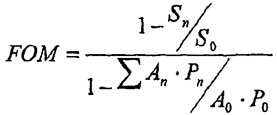
- So = Baseline thermally induced stress level
- An = Area associated with a specific surface heating rate. (n = 0 is the baseline case)
- Sn = Thermally induced stress level with the novel design
- Pn = Heating rate for a particular area
- The susceptor of the
bottom panel 20 illustrated inFigure 1 can be characterized as a baseline susceptor that is 180 millimeters by 180 millimeters. In the following, the susceptors of the first versions of thebottom panels Figures 8-10 are considered to be the same overall size as, and constructed in the same manner as, the baseline susceptor of thebottom panel 20 illustrated inFigure 1 , except for having the different arrangements of microwave interactive material as discussed above. The dashed lines inFigure 1 designate a quadrant of the baseline susceptor of thebottom panel 20. Likewise, dashed lines inFigures 8-10 respectively designate quadrants of the susceptors of thebottom panels - The following table (Table 1) provides a comparison between a quadrant of the baseline susceptor of the bottom panel 20 (
Figure 1 ) and quadrants of the susceptors of the first versions of thebottom panels 620, 720, 820 (Figures 8-10 ), with each being on one quadrant of a 260 millimeter diameter glass tray.Table 1 Design Susceptor area per quadrant (mm2) Reduction in thermally induced stress (N/m2) FOM susceptor of bottom panel 20 ( Figure 1 )8100 0% 0 version 1 of susceptor ofbottom panel 620 shown inFigure 8 7656 13.5% 2.45 version 1 of susceptor of bottom panel 720 shown inFigure 9 7659 13.5% 2.45 version 1 of susceptor ofbottom panel 820 shown inFigure 10 7657 12.5% 2.27 - As apparent from the above table, examples of the present invention can advantageously reduce thermally induced stress in turntable trays without unduly sacrificing susceptor effectiveness. As also apparent from the above table and regarding the FOM,
version 1 of the susceptor ofbottom panel 620 shown inFigure 8 ,version 1 of the susceptor of bottom panel 720 shown inFigure 9 , andversion 1 of the susceptor ofbottom panel 820 shown inFigure 10 each operate sufficiently similarly such that, for example, the beveled corners 854 (Figure 10 ) can be characterized as operating as though they at least generally have a radius of curvature, and thecorner regions 644, 750 (Figures 8 and9 ) can be characterized as being at least generally rectangular (e.g., each of thecorner regions beveled corners 854 shown inFigure 10 can be characterized as operating in substantially the same manner as the roundedbeveled corners Figures 8 and9 , and the roundedbeveled corners Figure 8 and9 can be characterized as operating in substantially the same manner as the straightbeveled corners 854. Statements made in this Detailed Description section of this disclosure about similarities are for purposes of illustration and not for the purpose of narrowing the scope of the presentation, and they should not be construed as any sort of suggestion that different embodiments or species of the present invention are patentably indistinct. -
Figures 14 and15 are charts that provide comparisons between susceptors, in accordance with an aspect of the present invention. Generally described,Figures 14 and15 illustrate theoretical computations run for the sixth embodiment of the present invention with varying radii both as the first version of the sixth embodiment (e.g., a "plain susceptor" with various beveled corners) and the second version of the sixth embodiment (e.g., a "plain susceptor / Focus QUIKWAVE brand susceptor combination" with various beveled corners). - More specifically, in each of
Figures 14 and15 , the data points represented as diamonds are for a First Series of Susceptors (e.g., "plain susceptors" with various beveled corners). Each susceptor of the First Series of Susceptors is 180 millimeters by 180 millimeters, and like the first version of the susceptor of the bottom panel 620 (Figure 8 ) of the sixth embodiment in that any beveled corners (e.g., like thebeveled corners 642 ofFigure 8 ) are defined by a radius of curvature having a center of curvature located at the center of the susceptor (e.g., at the center of the susceptor of the bottom panel 620). The difference between the susceptors of the First Series of Susceptors is that they each have a different radius of curvature for defining any beveled corners (e.g., beveled corners 642). For example, the First Series of Susceptors includes: - a susceptor that is 180 millimeters by 180 millimeters and otherwise like the first version of the susceptor of the
bottom panel 620 ofFigure 8 ; - a susceptor that is 180 millimeters by 180 millimeters and otherwise like the baseline susceptor of the
bottom panel 20 ofFigure 1 (i.e., a susceptor that is 180 millimeters by 180 millimeters and otherwise like the first version of the susceptor of thebottom panel 620 ofFigure 8 , except that the radius of curvature (for defining any beveled corners) is 127 millimeters); and - a susceptor that is 180 millimeters by 180 millimeters and otherwise like the susceptor of the
bottom panel 120 ofFigure 3A (i.e., a susceptor that is 180 millimeters by 180 millimeters and otherwise like the first version of the susceptor of thebottom panel 620 ofFigure 8 , except that the radius of curvature (for defining beveled corners) is 90 millimeters). - In each of
Figures 14 and15 , the data points represented as squares are for a Second Series of Susceptors (e.g., a "plain susceptor / Focus QUIKWAVE brand susceptor combinations" with various beveled corners). Each susceptor of this series is 180 millimeters by 180 millimeters, and like the second version of the susceptor of the bottom panel 620 (Figure 8 ) of the sixth embodiment in that any beveled corners (e.g., like thebeveled corners 642 ofFigure 8 ) are defined by a radius of curvature having a center of curvature located at the center of the susceptor (e.g., at the center of the susceptor of the bottom panel 620). The difference between the susceptors of the Second Series of Susceptors is that they each have a different radius of curvature for defining any beveled corners (e.g., beveled corners 642). For example, the Second Series of Susceptors includes: - a susceptor that is 180 millimeters by 180 millimeters and otherwise like the second version of the susceptor of the
bottom panel 620 ofFigure 8 ; - a susceptor that is 180 millimeters by 180 millimeters and otherwise like the baseline susceptor of the
bottom panel 20 ofFigure 1 (i.e., a susceptor that is 180 millimeters by 180 millimeters and otherwise like the second version of the susceptor of thebottom panel 620 ofFigure 8 , except that the radius of curvature (for defining any beveled corners) is 127 millimeters); and - a susceptor that is 180 millimeters by 180 millimeters and otherwise like the susceptor of the
bottom panel 220 ofFigure 4 (i.e., a susceptor that is 180 millimeters by 180 millimeters and otherwise like the second version of the susceptor of thebottom panel 620 ofFigure 8 , except that the radius of curvature (for defining beveled corners) is 90 millimeters). - As apparent from
Figure 14 , as a general rule and for comparable susceptors, beveling (e.g., rounding) the corners of microwave interactive material can reduce thermally induced stress in turntable trays, and thereby reduce the occurrences of damaging turntable trays (e.g., causing them to fracture). AlthoughFigure 14 is directed to rounding corners of continuous layers of microwave interactive material, it can also be advantageous to similarly bevel (e.g., round) corners of patterns of microwave interactive material. Accordingly, alternative embodiments of the present invention are directed to beveling corners of patterns of microwave interactive material, with that beveling corresponding to the herein described beveling of corners of continuous layers of microwave interactive material. As also apparent fromFigure 14 , as a general rule and for comparable susceptors, the Second Series of Susceptors provides a lesser reduction in thermally induced stress than the First Series of Susceptors. - As apparent from
Figure 15 , the Second Series of Susceptors is substantially more effective for cooking than the First Series of Susceptors, as indicated by the higher FOMs. Also apparent fromFigure 15 , there is an optimum effectiveness (i.e. where the FOM is at a maximum), and for the embodiments illustrated byFigure 15 the optimum effectiveness lies within a range of a radius of curvature of about 105 millimeters to a radius of curvature of about 110 millimeters. More generally, for the embodiments illustrated byFigure 15 the optimum effectiveness lies within a range of a radius of curvature of about 99 millimeters to a radius of curvature of about 112 millimeters. - Whereas 260 millimeter diameter glass turntable trays and susceptors that are 180 millimeters by 180 millimeters are mentioned in the foregoing, a wide variety of different sizes are within the scope of the present invention. For example, it is typical for turntable trays to be as small as 24.1 cm (9.5 inches) and as large as 41.9 cm (16.5 inches), and they can be a variety of sizes in between. Also, it is expected that differently sized turntable trays will be developed in the future, and such differently sized turntable trays are also within the scope of the present invention. In particular and as one example, it is expected that smaller microwave ovens with smaller turntable trays will be commercialized in the future.
- The above-discussed turntable trays can be conventional, and constructed of material such as Pyrex brand glass. It is believed that some conventional turntable trays, which are suitable for use in accordance with the present invention, may have a tensile strength of about 7 x 10⁶ N/m2, or the like. Turntable trays made of glass typically have no plastic deformation; therefore, they will typically break, rather than deform, if the tensile strength is exceeded. Nonetheless, the susceptors and other constructs of the present invention can operate advantageously with a variety of different turntable trays, with different tensile strengths and other different characteristics. As at least generally mentioned above, one aspect of the present invention pertains to configuring layer(s) of microwave interactive material that cover a turntable tray in a microwave oven so that, with the microwave oven providing a typical amount of microwave energy for heating and/or cooking food within the microwave oven, thermally induced stress in the turntable tray is less than the tensile strength of the turntable tray. More specifically, it may be desirable for the layer(s) of microwave interactive material to be configured so that the thermally induced stress in the turntable tray is less than a percentage of the tensile strength of the turntable tray, with the percentage being about 98%, about 95%, about 90%, about 80%, or about 70% or less.
- It will be understood by those skilled in the art that while the present invention has been discussed above with reference to exemplary embodiments, various additions, modifications and changes can be made thereto without departing from the scope of the invention as set forth in the following claims.
Claims (13)
- A method of heating food (123) in a microwave oven having a disk-shaped turntable tray (22, 622, 722, 822), the method comprising:providing a carton comprising a polygonal bottom panel (120, 220, 420, 520, 620, 720, 820), side panels (121), and a susceptor (132), the bottom panel (120, 220, 420, 520, 620, 720, 820) comprising a plurality of edges (134) and a plurality of corners (126), the side panels (121) respectively extending upwardly from the edges (134) of the bottom panel (120, 220, 420, 520, 620, 720, 820), the susceptor (132) being mounted to the bottom panel (120, 220, 420, 520, 620, 720, 820), the susceptor (132) comprising a layer of microwave interactive material (125,) that is generally polygonal-shaped, the layer of microwave interactive material (125) being operative for becoming hot when exposed to microwave energy, and the providing step comprisingoptimizing effectiveness of the susceptor (132), comprising extending the layer of microwave interactive material (125) substantially to the edges (134) of the bottom panel (120, 220, 420, 520, 620, 720, 820), so thatthe layer of microwave interactive material (125) comprises a plurality of edges (438, 638) that respectively are proximate the edges (134) of the bottom panel (120, 220, 420, 520, 620, 720, 820), andthe edges (438, 638) of the layer of microwave interactive material (125) respectively extending along the edges (134) of the bottom panel (120, 220, 420, 520, 620, 720, 820), andcontrolling stress in the tray (22, 622, 722, 822), comprising omitting the layer of microwave interactive material (125) from a substantial portion of each of the corners (126) of the bottom panel (120, 220, 420, 520, 620, 720, 820), so thatthe layer of microwave interactive material (125) comprises a plurality of beveled corners (128, 228, 434, 534, 642, 748, 854) that are respectively adjacent the corners (126) of the bottom panel (120, 220, 420, 520, 620, 720, 820), andeach beveled corner (128, 228, 434, 534, 642, 748, 854) is inwardly recessed from the respective adjacent corner of the bottom panel (120, 220, 420, 520, 620, 720, 820);placing the food (123) and the carton on the tray (22, 622, 722, 822) in the microwave oven, so that the tray (22, 622, 722, 822) is supporting the bottom panel (120, 220, 420, 520, 620, 720, 820) of the carton, and the susceptor (132) is supporting the food (123), wherein the placing step comprises arranging the carton in a predetermined position on the tray (22, 622, 722, 822) so that each beveled corner (128, 228, 434, 534, 642, 748, 854) is both proximate and inwardly recessed from an outer periphery of the tray (22, 622, 722, 822); andoperating the microwave oven while the carton is in the predetermined position on the tray (22, 622, 722, 822), so thatthe layer of microwave interactive material (125) is exposed to microwave energy and becomes hot and heats the food (123),the tray (22, 622, 722, 822) is heated by the hot layer of microwave interactive material (125) so that peak thermally induced stresses occur in the tray (22, 622, 722, 822) at locations proximate each beveled corner (128, 228, 434, 534, 642, 748, 854), characterized byeach of the peak thermally induced stresses is less than a predetermined amount in response to each of the corners of the layer of microwave interactive material (125) being beveled so that each of the corners (128, 228, 434, 534, 642, 748, 854) of the layer of microwave interactive material (125) is inwardly recessed from the outer periphery of the tray (22, 622, 722, 822), the tray (22, 622, 722, 822) has a tensile strength, and the predetermined amount is the tensile strength, so that each of the peak thermally induced stresses is less than the tensile strength of the tray (22, 622, 722, 822).
- The method according to claim 1, wherein the edges (438, 638) of the layer of microwave interactive material (125) are respectively substantially collinear with the edges (134) of the bottom panel (120, 220, 420, 520, 620, 720, 820).
- The method according to any of claims 1-2, wherein the arranging step comprises arranging the carton in the predetermined position on the tray (22, 622, 722, 822) so that each corner of the bottom panel (120, 220, 420, 520, 620, 720, 820) is inwardly recessed from the outer periphery of the tray (22, 622, 722, 822).
- The method according to any of claims 1-3, wherein the layer of microwave interactive material (125) extends to within about 2.54 mm (0.1 inches) of at least one of the edges (134) of the bottom panel (120, 220, 420, 520, 620, 720, 820).
- The method according to any of claims 1-4, wherein:the layer of microwave interactive material (125) has an optical density of less than about 0.5, andthe layer of microwave interactive material (125) has a thickness of less than about 200 angstroms.
- The method according to any of claims 1-5, wherein:the layer of microwave interactive material (125) is a first layer of microwave interactive material (125);the susceptor (132) further comprises a patterned layer of microwave interactive material that is operative for becoming hot when exposed to microwave energy;the patterned layer of microwave interactive material covers the corners (126) of the bottom panel (120, 220, 420, 520, 620, 720, 820); andper unit area, the first layer of microwave interactive material (125) is more absorbent of microwave energy than the patterned of microwave interactive material (125).
- A construct (120, 220, 420, 520, 620, 720, 820) for use in heating food (123) in a microwave oven having a disk-shaped turntable tray (22, 622, 722, 822), wherein:the construct (120, 220, 420, 520, 620, 720, 820) is for being placed on the tray (22, 622, 722, 822) in the microwave oven so that the tray (22, 622, 722, 822) is supporting the construct (120, 220, 420, 520, 620, 720, 820), and the construct (120, 220, 420, 520, 620, 720, 820) is supporting the food (123);the construct (120, 220, 420, 520, 620, 720, 820) comprises a susceptor (132) that is for supporting the food (123), the susceptor (132) comprises a layer of microwave interactive material (125) mounted to a support layer (127, 130), and the layer of microwave interactive material (125) is operative for becoming hot when exposed to microwave energy;the support layer (127, 130) is substantially polygonal-shaped, so that the support layer (127, 130) comprises a plurality of edges (134) and a plurality of corners (126);the layer of microwave interactive material (125) comprises a plurality of edges (438, 638) and a plurality of beveled corners (128, 228, 434, 534, 642, 748, 854) that are configured such that the layer of microwave interactive material (125) is generally polygonal-shaped;the layer of microwave interactive material (125) extends substantially to the edges (134) of the support layer (127, 130), so that the edges (438, 638) of the layer of microwave interactive material (125) respectively are proximate the edges (134) of the support layer (127, 130), and the edges (438, 638) of the layer of microwave interactive material (125) respectively extend along the edges (134) of the support layer (127, 130), for optimizing effectiveness of the susceptor (132);the beveled corners (128, 228, 434, 534, 642, 748, 854) of the layer of microwave interactive material (125) are respectively adjacent the corners (126) of the support layer (127, 130), and each beveled corner (128, 228, 434, 534, 642, 748, 854) is inwardly recessed from the respective adjacent corner of the support layer (127, 130), so that a substantial portion of each of the corners (126) of the support layer (127, 130) is not covered by the layer of microwave interactive material (125), for controlling stress in the tray (22, 622, 722, 822); andthe construct (120, 220, 420, 520, 620, 720, 820) is for being arranged in a predetermined position on the tray (22, 622, 722, 822) so that each beveled corner (128, 228, 434, 534, 642, 748, 854) is both proximate and inwardly recessed from an outer periphery of the tray (22, 622, 722, 822), and the layer of microwave interactive material (125) is operative for becoming hot in response to exposure to microwave energy while the construct (120, 220, 420, 520, 620, 720, 820) is in the predetermined position on the tray (22, 622, 722, 822), so thatthe food (123) is heated by the hot layer of microwave interactive material (125),the tray (22, 622, 722, 822) is heated by the hot layer of microwave interactive material (125) so that peak thermally induced stresses occur in the tray (22, 622, 722, 822) at locations proximate each beveled corner (128, 228, 434, 534, 642, 748, 854), characterized byeach of the peak thermally induced stresses is less than a predetermined amount in response to each of the corners (128, 228, 434, 534, 642, 748, 854) of the layer of microwave interactive material (125) being beveled so that each of the corners of the layer of microwave interactive material (125) is inwardly recessed from the outer periphery of the tray (22, 622, 722, 822), the tray (22, 622, 722, 822) has a tensile strength, and the predetermined amount is the tensile strength, so that each of the peak thermally induced stresses is less than the tensile strength of the tray (22, 622, 722, 822).
- The construct (120, 220, 420, 520, 620, 720, 820) according to claim 7, wherein the edges (438, 638) of the layer of microwave interactive material (125) are respectively substantially collinear with the edges (134) of the support layer (127, 130), for optimizing effectiveness of the susceptor (132).
- The construct (120, 220, 420, 520, 620, 720, 820) according to any of claims 7-8, wherein the construct (120, 220, 420, 520, 620, 720, 820) is for being arranged in the predetermined position on the tray (22, 622, 722, 822) so that each corner of the support layer (127, 130) is inwardly recessed from the outer periphery of the tray (22, 622, 722, 822).
- The construct (120, 220, 420, 520, 620, 720, 820) according to any of claims 7-9, wherein for each edge of the plurality of edges (134) of the support layer (127, 130), the layer of microwave interactive material (125) extends to within about 2.54 mm (0.1 inches) of the edge.
- The construct (120, 220, 420, 520, 620, 720, 820) according to any of claims 7-10, wherein:the layer of microwave interactive material (125) has an optical density of less than about 0.5, andthe layer of microwave interactive material has a thickness of less than about 200 angstroms.
- The construct (120, 220, 420, 520, 620, 720, 820) according to any of claims 7-11, wherein:the construct (120, 220, 420, 520, 620, 720, 820) is a carton;the support layer (127, 130) is a polygonal bottom panel (120, 220, 420, 520, 620, 720, 820) of the carton; andthe carton comprises side panels (121) respectively extending upwardly from the edges (134) of the bottom panel (120, 220, 420, 520, 620, 720, 820).
- The construct (120, 220, 420, 520, 620, 720, 820) according to any of claims 7-12, wherein:the layer of microwave interactive material (125) is a first layer of microwave interactive material (125);the susceptor (132) further comprises a patterned layer of microwave interactive material that is operative for becoming hot when exposed to microwave energy;the patterned layer of microwave interactive material covers the corners (126) of the support layer (127, 130); andper unit area, the first layer of microwave interactive material (125) is more absorbent of microwave energy than the patterned of microwave interactive material (125).
Applications Claiming Priority (3)
| Application Number | Priority Date | Filing Date | Title |
|---|---|---|---|
| US69188505P | 2005-06-17 | 2005-06-17 | |
| EP06773427.7A EP1899243B1 (en) | 2005-06-17 | 2006-06-16 | Susceptors capable of balancing stress and effectiveness |
| PCT/US2006/023617 WO2006138645A2 (en) | 2005-06-17 | 2006-06-16 | Susceptor capable of balancing thermally induced stress |
Related Parent Applications (3)
| Application Number | Title | Priority Date | Filing Date |
|---|---|---|---|
| EP06773427.7 Division | 2006-06-16 | ||
| EP06773427.7A Division-Into EP1899243B1 (en) | 2005-06-17 | 2006-06-16 | Susceptors capable of balancing stress and effectiveness |
| EP06773427.7A Division EP1899243B1 (en) | 2005-06-17 | 2006-06-16 | Susceptors capable of balancing stress and effectiveness |
Publications (3)
| Publication Number | Publication Date |
|---|---|
| EP2578516A2 EP2578516A2 (en) | 2013-04-10 |
| EP2578516A3 EP2578516A3 (en) | 2013-08-21 |
| EP2578516B1 true EP2578516B1 (en) | 2021-05-05 |
Family
ID=37137475
Family Applications (2)
| Application Number | Title | Priority Date | Filing Date |
|---|---|---|---|
| EP12008247.4A Active EP2578516B1 (en) | 2005-06-17 | 2006-06-16 | A method of heating food and a construct for use therein |
| EP06773427.7A Active EP1899243B1 (en) | 2005-06-17 | 2006-06-16 | Susceptors capable of balancing stress and effectiveness |
Family Applications After (1)
| Application Number | Title | Priority Date | Filing Date |
|---|---|---|---|
| EP06773427.7A Active EP1899243B1 (en) | 2005-06-17 | 2006-06-16 | Susceptors capable of balancing stress and effectiveness |
Country Status (5)
| Country | Link |
|---|---|
| US (4) | US20070023426A1 (en) |
| EP (2) | EP2578516B1 (en) |
| CA (1) | CA2612088C (en) |
| ES (2) | ES2881533T3 (en) |
| WO (1) | WO2006138645A2 (en) |
Families Citing this family (18)
| Publication number | Priority date | Publication date | Assignee | Title |
|---|---|---|---|---|
| EP2181939B1 (en) * | 2002-02-08 | 2015-05-20 | Graphic Packaging International, Inc. | Microwave interactive packaging material |
| JP4327205B2 (en) * | 2004-02-09 | 2009-09-09 | グラフィック パッケージング インターナショナル インコーポレイテッド | Microwave cooking package |
| EP2578516B1 (en) | 2005-06-17 | 2021-05-05 | Graphic Packaging International, LLC | A method of heating food and a construct for use therein |
| CA2621723C (en) * | 2007-02-15 | 2014-05-20 | Graphic Packaging International, Inc. | Microwave energy interactive insulating structure |
| WO2008143671A1 (en) * | 2007-05-21 | 2008-11-27 | Coffee Technologies International Inc. | Assembled container for roasting food |
| EP2265514B1 (en) * | 2008-03-27 | 2016-02-10 | Graphic Packaging International, Inc. | Self-venting microwave heating package |
| US8247750B2 (en) | 2008-03-27 | 2012-08-21 | Graphic Packaging International, Inc. | Construct for cooking raw dough product in a microwave oven |
| JP5788792B2 (en) * | 2008-07-11 | 2015-10-07 | グラフィック パッケージング インターナショナル インコーポレイテッド | Microwave heating vessel |
| DE102014112423B4 (en) * | 2014-08-29 | 2017-09-28 | Miele & Cie. Kg | cooking system |
| US10251223B2 (en) * | 2015-05-20 | 2019-04-02 | Illinois Tool Works Inc. | Apparatus for providing customizable heat zones in an oven |
| WO2017066531A1 (en) | 2015-10-15 | 2017-04-20 | Graphic Packaging International, Inc. | Microwave packaging |
| EP3464113A4 (en) | 2016-06-03 | 2019-11-13 | Graphic Packaging International, LLC | PACKAGING MATERIAL FOR MICROWAVE |
| US10061285B1 (en) | 2017-04-17 | 2018-08-28 | Silicon Valley Factory LLC | Encoding a custom cooking program |
| US10009963B1 (en) | 2017-04-17 | 2018-06-26 | Silicon Valley Factory LLC | Decoding a custom cooking program |
| US10070485B1 (en) | 2017-04-17 | 2018-09-04 | Silicon Valley Factory LLC | Automatic heating system and method |
| US20190002183A1 (en) * | 2017-06-28 | 2019-01-03 | Kraft Foods Group Brands Llc | Microwaveable Packaged Food Product |
| US11254044B2 (en) * | 2018-05-23 | 2022-02-22 | Justin Roberts | Disposable microwave oven liner |
| JP2024005339A (en) * | 2022-06-30 | 2024-01-17 | 味の素株式会社 | Microwave heating set and packaging |
Family Cites Families (71)
| Publication number | Priority date | Publication date | Assignee | Title |
|---|---|---|---|---|
| US3302632A (en) * | 1963-12-06 | 1967-02-07 | Wells Mfg Company | Microwave cooking utensil |
| US3547661A (en) * | 1968-10-07 | 1970-12-15 | Teckton Inc | Container and food heating method |
| US3662139A (en) * | 1970-03-04 | 1972-05-09 | Varian Associates | Cavity resonator having means for reducing leakage of r.f. energy at a covered access point |
| US3936626A (en) * | 1972-10-25 | 1976-02-03 | Chemetron Corporation | Method of heating comestibles |
| US3865301A (en) * | 1973-11-15 | 1975-02-11 | Trans World Services | Partially shielded food package for dielectric heating |
| US4013798A (en) * | 1973-11-21 | 1977-03-22 | Teckton, Inc. | Selectively ventable food package and micro-wave shielding device |
| US4020310A (en) * | 1975-03-20 | 1977-04-26 | Souder Jr James J | Container for inductively heating food |
| CA1141273A (en) * | 1981-09-11 | 1983-02-15 | Donald E. Beckett | Formation of packaging material |
| US4574174A (en) * | 1984-05-21 | 1986-03-04 | Mcgonigle Thomas P | Convenience dinner container and method |
| US4552614A (en) * | 1984-06-18 | 1985-11-12 | Beckett Packaging Limited | Demetallizing method and apparatus |
| US4558198A (en) * | 1984-12-03 | 1985-12-10 | Aluminum Company Of America | Metal container system for use in microwave ovens |
| US4676857A (en) * | 1986-01-17 | 1987-06-30 | Scharr Industries Inc. | Method of making microwave heating material |
| US4865921A (en) * | 1987-03-10 | 1989-09-12 | James Riker Corporation Of Virginia | Microwave interactive laminate |
| USRE34683E (en) * | 1987-03-10 | 1994-08-02 | James River Corporation Of Virginia | Control of microwave interactive heating by patterned deactivation |
| US4883936A (en) * | 1988-09-01 | 1989-11-28 | James River Corporation | Control of microwave interactive heating by patterned deactivation |
| US4927991A (en) * | 1987-11-10 | 1990-05-22 | The Pillsbury Company | Susceptor in combination with grid for microwave oven package |
| CA1313231C (en) * | 1987-11-18 | 1993-01-26 | Richard M. Keefer | Microwave heating |
| US4908246A (en) * | 1988-01-26 | 1990-03-13 | James River Corporation | Metalized microwave interactive laminate and process for mechanically deactivating a selected area of microwave interactive laminate |
| US4972059A (en) | 1988-02-29 | 1990-11-20 | The Pillsbury Company | Method and apparatus for adjusting the temperature profile of food products during microwave heating |
| US4866232A (en) | 1988-04-06 | 1989-09-12 | Packaging Corporation Of America | Food package for use in a microwave oven |
| US5177332A (en) * | 1988-04-29 | 1993-01-05 | E. I. Du Pont De Nemours And Company | Microwave energy susceptible conformable laminate packaging materials |
| AU3761189A (en) | 1988-05-23 | 1989-12-12 | Pillsbury Company, The | Susceptors having disrupted regions for differential heating in a microwave oven |
| US5220143A (en) * | 1988-05-23 | 1993-06-15 | The Pillsbury Company | Susceptors having disrupted regions for differential heating in a microwave oven |
| US4896009A (en) * | 1988-07-11 | 1990-01-23 | James River Corporation | Gas permeable microwave reactive package |
| US5410135A (en) * | 1988-09-01 | 1995-04-25 | James River Paper Company, Inc. | Self limiting microwave heaters |
| US4890439A (en) * | 1988-11-09 | 1990-01-02 | James River Corporation | Flexible disposable material for forming a food container for microwave cooking |
| US5239153A (en) * | 1988-11-28 | 1993-08-24 | Beckett Industries Inc. | Differential thermal heating in microwave oven packages |
| US5519195A (en) * | 1989-02-09 | 1996-05-21 | Beckett Technologies Corp. | Methods and devices used in the microwave heating of foods and other materials |
| US5149396A (en) * | 1989-06-21 | 1992-09-22 | Golden Valley Microwave Foods Inc. | Susceptor for microwave heating and method |
| US4959120A (en) * | 1989-06-21 | 1990-09-25 | Golden Valley Microwave Foods, Inc. | Demetallization of metal films |
| US5038009A (en) * | 1989-11-17 | 1991-08-06 | Union Camp Corporation | Printed microwave susceptor and packaging containing the susceptor |
| US4970358A (en) * | 1989-12-22 | 1990-11-13 | Golden Valley Microwave Foods Inc. | Microwave susceptor with attenuator for heat control |
| CA2009207A1 (en) * | 1990-02-02 | 1991-08-02 | D. Gregory Beckett | Controlled heating of foodstuffs by microwave energy |
| GB2250408B (en) * | 1990-12-01 | 1995-08-02 | Waddingtons Cartons Ltd | Improvements relating to the microwave heating of foodstuff |
| US5254821A (en) * | 1991-01-15 | 1993-10-19 | Advanced Dielectric Technologies, Inc. | Selectively microwave-permeable membrane susceptor systems |
| US5213902A (en) * | 1991-02-19 | 1993-05-25 | Beckett Industries Inc. | Microwave oven package |
| KR930701904A (en) * | 1991-06-05 | 1993-06-12 | 후꾸가와 신이찌 | Method of forming a heating layer in the microwave absorption heating element and the microwave absorption heating element |
| US5260537A (en) * | 1991-06-17 | 1993-11-09 | Beckett Industries Inc. | Microwave heating structure |
| GB9114068D0 (en) * | 1991-06-28 | 1991-08-14 | Beckett Ind Inc | Microwave heating device |
| ATE141231T1 (en) * | 1991-07-16 | 1996-08-15 | Unilever Nv | SUSCEPTOR AND COOKIE DOUGH |
| US5405663A (en) | 1991-11-12 | 1995-04-11 | Hunt-Wesson, Inc. | Microwave package laminate with extrusion bonded susceptor |
| GB9201932D0 (en) * | 1992-01-29 | 1992-03-18 | Beckett Ind Inc | Novel microwave heating structure |
| US5357086A (en) * | 1992-03-16 | 1994-10-18 | Golden Valley Microwave Foods Inc. | Microwave corn popping package |
| US5352465A (en) * | 1992-08-04 | 1994-10-04 | Vendtron, Inc. | Disposable, microwaveable, food storage container |
| US5424517A (en) * | 1993-10-27 | 1995-06-13 | James River Paper Company, Inc. | Microwave impedance matching film for microwave cooking |
| US5530231A (en) * | 1994-01-25 | 1996-06-25 | Advanced Deposition Technologies, Inc. | Multilayer fused microwave conductive structure |
| US5585027A (en) * | 1994-06-10 | 1996-12-17 | Young; Robert C. | Microwave susceptive reheating support with perforations enabling change of size and/or shape of the substrate |
| US5864123A (en) * | 1995-06-02 | 1999-01-26 | Keefer; Richard M. | Smart microwave packaging structures |
| DE69634455T2 (en) * | 1995-09-18 | 2006-02-02 | Graphic Packaging International, Inc., Golden | Microwaveable container |
| US5800724A (en) * | 1996-02-14 | 1998-09-01 | Fort James Corporation | Patterned metal foil laminate and method for making same |
| US5759422A (en) * | 1996-02-14 | 1998-06-02 | Fort James Corporation | Patterned metal foil laminate and method for making same |
| AU4006197A (en) * | 1996-08-26 | 1998-03-19 | Fort James Corporation | Microwavable package |
| CA2264121C (en) * | 1996-08-26 | 2004-07-20 | Fort James Corporation | Microwavable container |
| DE69819419T2 (en) * | 1997-01-29 | 2004-10-07 | Graphic Packaging Corp | MICROWAVE OVEN WITH SEVERAL HEATING ELEMENTS ARRANGED IN A LOOP |
| WO1998035887A1 (en) | 1997-02-12 | 1998-08-20 | Fort James Corporation | Patterned microwave oven susceptor |
| US6414290B1 (en) * | 1998-03-19 | 2002-07-02 | Graphic Packaging Corporation | Patterned microwave susceptor |
| US6433322B2 (en) * | 1999-09-20 | 2002-08-13 | Graphic Packaging Corporation | Abuse-tolerant metallic packaging materials for microwave cooking |
| US6204492B1 (en) * | 1999-09-20 | 2001-03-20 | Graphic Packaging Corporation | Abuse-tolerant metallic packaging materials for microwave cooking |
| US6501059B1 (en) | 1999-09-27 | 2002-12-31 | Roy Lee Mast | Heavy-metal microwave formations and methods |
| US6717121B2 (en) * | 2001-09-28 | 2004-04-06 | Graphic Packaging International, Inc. | Patterned microwave susceptor element and microwave container incorporating same |
| US20030085233A1 (en) * | 2001-11-05 | 2003-05-08 | Winkleman Robert E. | Bottle nanny |
| US6677563B2 (en) * | 2001-12-14 | 2004-01-13 | Graphic Packaging Corporation | Abuse-tolerant metallic pattern arrays for microwave packaging materials |
| EP2181939B1 (en) * | 2002-02-08 | 2015-05-20 | Graphic Packaging International, Inc. | Microwave interactive packaging material |
| US20050184066A1 (en) | 2003-05-22 | 2005-08-25 | Brooks Joseph R. | Susceptor cooking trays and kits for microwavable food products |
| US20040238535A1 (en) * | 2003-05-29 | 2004-12-02 | Mast Roy Lee | Package with embossed food support for microwave cooking |
| US7108878B2 (en) * | 2003-08-18 | 2006-09-19 | Promark Brands Inc. | Process for making microwavable French fries |
| ATE547348T1 (en) * | 2004-08-25 | 2012-03-15 | Graphic Packaging Int Inc | ABSORBENT MICROWAVE INTERACTIVE PACKAGING |
| ES2586441T3 (en) * | 2005-04-14 | 2016-10-14 | Graphic Packaging International, Inc. | Interactive insulating material with expandable microwave energy lasting |
| JP4856176B2 (en) * | 2005-05-25 | 2012-01-18 | グラフィック パッケージング インターナショナル インコーポレイテッド | Microwave packaging for multi-component meals |
| EP2578516B1 (en) | 2005-06-17 | 2021-05-05 | Graphic Packaging International, LLC | A method of heating food and a construct for use therein |
| US8247750B2 (en) * | 2008-03-27 | 2012-08-21 | Graphic Packaging International, Inc. | Construct for cooking raw dough product in a microwave oven |
-
2006
- 2006-06-16 EP EP12008247.4A patent/EP2578516B1/en active Active
- 2006-06-16 WO PCT/US2006/023617 patent/WO2006138645A2/en not_active Ceased
- 2006-06-16 EP EP06773427.7A patent/EP1899243B1/en active Active
- 2006-06-16 ES ES12008247T patent/ES2881533T3/en active Active
- 2006-06-16 CA CA2612088A patent/CA2612088C/en active Active
- 2006-06-16 US US11/454,273 patent/US20070023426A1/en not_active Abandoned
- 2006-06-16 ES ES06773427T patent/ES2751955T3/en active Active
-
2009
- 2009-01-14 US US12/321,114 patent/US20090184111A1/en not_active Abandoned
-
2011
- 2011-11-01 US US13/286,724 patent/US8847132B2/en active Active
-
2014
- 2014-08-29 US US14/473,145 patent/US9844102B2/en active Active
Also Published As
| Publication number | Publication date |
|---|---|
| EP1899243B1 (en) | 2019-09-18 |
| US8847132B2 (en) | 2014-09-30 |
| EP1899243A2 (en) | 2008-03-19 |
| EP2578516A3 (en) | 2013-08-21 |
| WO2006138645A2 (en) | 2006-12-28 |
| US20120043317A1 (en) | 2012-02-23 |
| WO2006138645A3 (en) | 2007-03-01 |
| ES2881533T3 (en) | 2021-11-29 |
| US9844102B2 (en) | 2017-12-12 |
| ES2751955T3 (en) | 2020-04-02 |
| US20140370168A1 (en) | 2014-12-18 |
| US20070023426A1 (en) | 2007-02-01 |
| CA2612088A1 (en) | 2006-12-28 |
| US20090184111A1 (en) | 2009-07-23 |
| EP2578516A2 (en) | 2013-04-10 |
| CA2612088C (en) | 2012-05-15 |
Similar Documents
| Publication | Publication Date | Title |
|---|---|---|
| US9844102B2 (en) | Susceptors capable of balancing stress and effectiveness | |
| EP2506678B1 (en) | Elevated microwave heating construct | |
| EP2453177B1 (en) | Even heating microwavable container | |
| CA2650265C (en) | Cooking package | |
| EP1960289B1 (en) | Package with removable portion | |
| US9227752B2 (en) | Elevated microwave heating tray | |
| CA2729600C (en) | Cooking package | |
| US20100055260A1 (en) | Package for heating a food product |
Legal Events
| Date | Code | Title | Description |
|---|---|---|---|
| PUAI | Public reference made under article 153(3) epc to a published international application that has entered the european phase |
Free format text: ORIGINAL CODE: 0009012 |
|
| AC | Divisional application: reference to earlier application |
Ref document number: 1899243 Country of ref document: EP Kind code of ref document: P |
|
| AK | Designated contracting states |
Kind code of ref document: A2 Designated state(s): AT BE BG CH CY CZ DE DK EE ES FI FR GB GR HU IE IS IT LI LT LU LV MC NL PL PT RO SE SI SK TR |
|
| PUAL | Search report despatched |
Free format text: ORIGINAL CODE: 0009013 |
|
| AK | Designated contracting states |
Kind code of ref document: A3 Designated state(s): AT BE BG CH CY CZ DE DK EE ES FI FR GB GR HU IE IS IT LI LT LU LV MC NL PL PT RO SE SI SK TR |
|
| RIC1 | Information provided on ipc code assigned before grant |
Ipc: B65D 81/34 20060101AFI20130717BHEP Ipc: H05B 6/64 20060101ALN20130717BHEP |
|
| 17P | Request for examination filed |
Effective date: 20140221 |
|
| RBV | Designated contracting states (corrected) |
Designated state(s): AT BE BG CH CY CZ DE DK EE ES FI FR GB GR HU IE IS IT LI LT LU LV MC NL PL PT RO SE SI SK TR |
|
| STAA | Information on the status of an ep patent application or granted ep patent |
Free format text: STATUS: EXAMINATION IS IN PROGRESS |
|
| 17Q | First examination report despatched |
Effective date: 20170724 |
|
| RAP1 | Party data changed (applicant data changed or rights of an application transferred) |
Owner name: GRAPHIC PACKAGING INTERNATIONAL, LLC |
|
| RIC1 | Information provided on ipc code assigned before grant |
Ipc: H05B 6/64 20060101ALN20201006BHEP Ipc: B65D 81/34 20060101AFI20201006BHEP |
|
| GRAP | Despatch of communication of intention to grant a patent |
Free format text: ORIGINAL CODE: EPIDOSNIGR1 |
|
| STAA | Information on the status of an ep patent application or granted ep patent |
Free format text: STATUS: GRANT OF PATENT IS INTENDED |
|
| RIC1 | Information provided on ipc code assigned before grant |
Ipc: H05B 6/64 20060101ALN20201109BHEP Ipc: B65D 81/34 20060101AFI20201109BHEP |
|
| INTG | Intention to grant announced |
Effective date: 20201126 |
|
| GRAS | Grant fee paid |
Free format text: ORIGINAL CODE: EPIDOSNIGR3 |
|
| GRAA | (expected) grant |
Free format text: ORIGINAL CODE: 0009210 |
|
| STAA | Information on the status of an ep patent application or granted ep patent |
Free format text: STATUS: THE PATENT HAS BEEN GRANTED |
|
| AC | Divisional application: reference to earlier application |
Ref document number: 1899243 Country of ref document: EP Kind code of ref document: P |
|
| AK | Designated contracting states |
Kind code of ref document: B1 Designated state(s): AT BE BG CH CY CZ DE DK EE ES FI FR GB GR HU IE IS IT LI LT LU LV MC NL PL PT RO SE SI SK TR |
|
| REG | Reference to a national code |
Ref country code: GB Ref legal event code: FG4D |
|
| REG | Reference to a national code |
Ref country code: CH Ref legal event code: EP |
|
| REG | Reference to a national code |
Ref country code: AT Ref legal event code: REF Ref document number: 1389577 Country of ref document: AT Kind code of ref document: T Effective date: 20210515 |
|
| REG | Reference to a national code |
Ref country code: IE Ref legal event code: FG4D |
|
| REG | Reference to a national code |
Ref country code: DE Ref legal event code: R096 Ref document number: 602006060055 Country of ref document: DE |
|
| REG | Reference to a national code |
Ref country code: NL Ref legal event code: FP |
|
| REG | Reference to a national code |
Ref country code: LT Ref legal event code: MG9D |
|
| REG | Reference to a national code |
Ref country code: AT Ref legal event code: MK05 Ref document number: 1389577 Country of ref document: AT Kind code of ref document: T Effective date: 20210505 |
|
| PG25 | Lapsed in a contracting state [announced via postgrant information from national office to epo] |
Ref country code: AT Free format text: LAPSE BECAUSE OF FAILURE TO SUBMIT A TRANSLATION OF THE DESCRIPTION OR TO PAY THE FEE WITHIN THE PRESCRIBED TIME-LIMIT Effective date: 20210505 Ref country code: BG Free format text: LAPSE BECAUSE OF FAILURE TO SUBMIT A TRANSLATION OF THE DESCRIPTION OR TO PAY THE FEE WITHIN THE PRESCRIBED TIME-LIMIT Effective date: 20210805 Ref country code: FI Free format text: LAPSE BECAUSE OF FAILURE TO SUBMIT A TRANSLATION OF THE DESCRIPTION OR TO PAY THE FEE WITHIN THE PRESCRIBED TIME-LIMIT Effective date: 20210505 Ref country code: LT Free format text: LAPSE BECAUSE OF FAILURE TO SUBMIT A TRANSLATION OF THE DESCRIPTION OR TO PAY THE FEE WITHIN THE PRESCRIBED TIME-LIMIT Effective date: 20210505 |
|
| REG | Reference to a national code |
Ref country code: ES Ref legal event code: FG2A Ref document number: 2881533 Country of ref document: ES Kind code of ref document: T3 Effective date: 20211129 |
|
| PG25 | Lapsed in a contracting state [announced via postgrant information from national office to epo] |
Ref country code: SE Free format text: LAPSE BECAUSE OF FAILURE TO SUBMIT A TRANSLATION OF THE DESCRIPTION OR TO PAY THE FEE WITHIN THE PRESCRIBED TIME-LIMIT Effective date: 20210505 Ref country code: IS Free format text: LAPSE BECAUSE OF FAILURE TO SUBMIT A TRANSLATION OF THE DESCRIPTION OR TO PAY THE FEE WITHIN THE PRESCRIBED TIME-LIMIT Effective date: 20210905 Ref country code: GR Free format text: LAPSE BECAUSE OF FAILURE TO SUBMIT A TRANSLATION OF THE DESCRIPTION OR TO PAY THE FEE WITHIN THE PRESCRIBED TIME-LIMIT Effective date: 20210806 Ref country code: LV Free format text: LAPSE BECAUSE OF FAILURE TO SUBMIT A TRANSLATION OF THE DESCRIPTION OR TO PAY THE FEE WITHIN THE PRESCRIBED TIME-LIMIT Effective date: 20210505 Ref country code: PL Free format text: LAPSE BECAUSE OF FAILURE TO SUBMIT A TRANSLATION OF THE DESCRIPTION OR TO PAY THE FEE WITHIN THE PRESCRIBED TIME-LIMIT Effective date: 20210505 Ref country code: PT Free format text: LAPSE BECAUSE OF FAILURE TO SUBMIT A TRANSLATION OF THE DESCRIPTION OR TO PAY THE FEE WITHIN THE PRESCRIBED TIME-LIMIT Effective date: 20210906 |
|
| PG25 | Lapsed in a contracting state [announced via postgrant information from national office to epo] |
Ref country code: CZ Free format text: LAPSE BECAUSE OF FAILURE TO SUBMIT A TRANSLATION OF THE DESCRIPTION OR TO PAY THE FEE WITHIN THE PRESCRIBED TIME-LIMIT Effective date: 20210505 Ref country code: EE Free format text: LAPSE BECAUSE OF FAILURE TO SUBMIT A TRANSLATION OF THE DESCRIPTION OR TO PAY THE FEE WITHIN THE PRESCRIBED TIME-LIMIT Effective date: 20210505 Ref country code: DK Free format text: LAPSE BECAUSE OF FAILURE TO SUBMIT A TRANSLATION OF THE DESCRIPTION OR TO PAY THE FEE WITHIN THE PRESCRIBED TIME-LIMIT Effective date: 20210505 Ref country code: SK Free format text: LAPSE BECAUSE OF FAILURE TO SUBMIT A TRANSLATION OF THE DESCRIPTION OR TO PAY THE FEE WITHIN THE PRESCRIBED TIME-LIMIT Effective date: 20210505 Ref country code: RO Free format text: LAPSE BECAUSE OF FAILURE TO SUBMIT A TRANSLATION OF THE DESCRIPTION OR TO PAY THE FEE WITHIN THE PRESCRIBED TIME-LIMIT Effective date: 20210505 |
|
| REG | Reference to a national code |
Ref country code: CH Ref legal event code: PL |
|
| REG | Reference to a national code |
Ref country code: DE Ref legal event code: R097 Ref document number: 602006060055 Country of ref document: DE |
|
| PLBE | No opposition filed within time limit |
Free format text: ORIGINAL CODE: 0009261 |
|
| STAA | Information on the status of an ep patent application or granted ep patent |
Free format text: STATUS: NO OPPOSITION FILED WITHIN TIME LIMIT |
|
| PG25 | Lapsed in a contracting state [announced via postgrant information from national office to epo] |
Ref country code: MC Free format text: LAPSE BECAUSE OF FAILURE TO SUBMIT A TRANSLATION OF THE DESCRIPTION OR TO PAY THE FEE WITHIN THE PRESCRIBED TIME-LIMIT Effective date: 20210505 Ref country code: LU Free format text: LAPSE BECAUSE OF NON-PAYMENT OF DUE FEES Effective date: 20210616 |
|
| 26N | No opposition filed |
Effective date: 20220208 |
|
| PG25 | Lapsed in a contracting state [announced via postgrant information from national office to epo] |
Ref country code: LI Free format text: LAPSE BECAUSE OF NON-PAYMENT OF DUE FEES Effective date: 20210630 Ref country code: IE Free format text: LAPSE BECAUSE OF NON-PAYMENT OF DUE FEES Effective date: 20210616 Ref country code: CH Free format text: LAPSE BECAUSE OF NON-PAYMENT OF DUE FEES Effective date: 20210630 |
|
| PG25 | Lapsed in a contracting state [announced via postgrant information from national office to epo] |
Ref country code: IS Free format text: LAPSE BECAUSE OF FAILURE TO SUBMIT A TRANSLATION OF THE DESCRIPTION OR TO PAY THE FEE WITHIN THE PRESCRIBED TIME-LIMIT Effective date: 20210905 |
|
| PG25 | Lapsed in a contracting state [announced via postgrant information from national office to epo] |
Ref country code: IT Free format text: LAPSE BECAUSE OF FAILURE TO SUBMIT A TRANSLATION OF THE DESCRIPTION OR TO PAY THE FEE WITHIN THE PRESCRIBED TIME-LIMIT Effective date: 20210505 |
|
| PG25 | Lapsed in a contracting state [announced via postgrant information from national office to epo] |
Ref country code: HU Free format text: LAPSE BECAUSE OF FAILURE TO SUBMIT A TRANSLATION OF THE DESCRIPTION OR TO PAY THE FEE WITHIN THE PRESCRIBED TIME-LIMIT; INVALID AB INITIO Effective date: 20060616 Ref country code: CY Free format text: LAPSE BECAUSE OF FAILURE TO SUBMIT A TRANSLATION OF THE DESCRIPTION OR TO PAY THE FEE WITHIN THE PRESCRIBED TIME-LIMIT Effective date: 20210505 |
|
| PG25 | Lapsed in a contracting state [announced via postgrant information from national office to epo] |
Ref country code: TR Free format text: LAPSE BECAUSE OF FAILURE TO SUBMIT A TRANSLATION OF THE DESCRIPTION OR TO PAY THE FEE WITHIN THE PRESCRIBED TIME-LIMIT Effective date: 20210505 |
|
| PGFP | Annual fee paid to national office [announced via postgrant information from national office to epo] |
Ref country code: DE Payment date: 20250627 Year of fee payment: 20 |
|
| PGFP | Annual fee paid to national office [announced via postgrant information from national office to epo] |
Ref country code: GB Payment date: 20250627 Year of fee payment: 20 |
|
| PGFP | Annual fee paid to national office [announced via postgrant information from national office to epo] |
Ref country code: NL Payment date: 20250626 Year of fee payment: 20 Ref country code: BE Payment date: 20250627 Year of fee payment: 20 |
|
| PGFP | Annual fee paid to national office [announced via postgrant information from national office to epo] |
Ref country code: FR Payment date: 20250625 Year of fee payment: 20 |
|
| PGFP | Annual fee paid to national office [announced via postgrant information from national office to epo] |
Ref country code: ES Payment date: 20250701 Year of fee payment: 20 |