EP2573859B1 - Device and method for calculating a value of a rechargeable battery - Google Patents
Device and method for calculating a value of a rechargeable battery Download PDFInfo
- Publication number
- EP2573859B1 EP2573859B1 EP10851725.1A EP10851725A EP2573859B1 EP 2573859 B1 EP2573859 B1 EP 2573859B1 EP 10851725 A EP10851725 A EP 10851725A EP 2573859 B1 EP2573859 B1 EP 2573859B1
- Authority
- EP
- European Patent Office
- Prior art keywords
- battery
- capacity
- rechargeable
- lithium ion
- open circuit
- Prior art date
- Legal status (The legal status is an assumption and is not a legal conclusion. Google has not performed a legal analysis and makes no representation as to the accuracy of the status listed.)
- Active
Links
Images


Classifications
-
- H—ELECTRICITY
- H01—ELECTRIC ELEMENTS
- H01M—PROCESSES OR MEANS, e.g. BATTERIES, FOR THE DIRECT CONVERSION OF CHEMICAL ENERGY INTO ELECTRICAL ENERGY
- H01M10/00—Secondary cells; Manufacture thereof
- H01M10/42—Methods or arrangements for servicing or maintenance of secondary cells or secondary half-cells
- H01M10/48—Accumulators combined with arrangements for measuring, testing or indicating the condition of cells, e.g. the level or density of the electrolyte
-
- G—PHYSICS
- G01—MEASURING; TESTING
- G01R—MEASURING ELECTRIC VARIABLES; MEASURING MAGNETIC VARIABLES
- G01R31/00—Arrangements for testing electric properties; Arrangements for locating electric faults; Arrangements for electrical testing characterised by what is being tested not provided for elsewhere
- G01R31/36—Arrangements for testing, measuring or monitoring the electrical condition of accumulators or electric batteries, e.g. capacity or state of charge [SoC]
- G01R31/389—Measuring internal impedance, internal conductance or related variables
-
- H—ELECTRICITY
- H01—ELECTRIC ELEMENTS
- H01M—PROCESSES OR MEANS, e.g. BATTERIES, FOR THE DIRECT CONVERSION OF CHEMICAL ENERGY INTO ELECTRICAL ENERGY
- H01M10/00—Secondary cells; Manufacture thereof
- H01M10/54—Reclaiming serviceable parts of waste accumulators
-
- H—ELECTRICITY
- H01—ELECTRIC ELEMENTS
- H01M—PROCESSES OR MEANS, e.g. BATTERIES, FOR THE DIRECT CONVERSION OF CHEMICAL ENERGY INTO ELECTRICAL ENERGY
- H01M50/00—Constructional details or processes of manufacture of the non-active parts of electrochemical cells other than fuel cells, e.g. hybrid cells
- H01M50/20—Mountings; Secondary casings or frames; Racks, modules or packs; Suspension devices; Shock absorbers; Transport or carrying devices; Holders
- H01M50/204—Racks, modules or packs for multiple batteries or multiple cells
- H01M50/207—Racks, modules or packs for multiple batteries or multiple cells characterised by their shape
- H01M50/209—Racks, modules or packs for multiple batteries or multiple cells characterised by their shape adapted for prismatic or rectangular cells
-
- H—ELECTRICITY
- H01—ELECTRIC ELEMENTS
- H01M—PROCESSES OR MEANS, e.g. BATTERIES, FOR THE DIRECT CONVERSION OF CHEMICAL ENERGY INTO ELECTRICAL ENERGY
- H01M50/00—Constructional details or processes of manufacture of the non-active parts of electrochemical cells other than fuel cells, e.g. hybrid cells
- H01M50/20—Mountings; Secondary casings or frames; Racks, modules or packs; Suspension devices; Shock absorbers; Transport or carrying devices; Holders
- H01M50/218—Mountings; Secondary casings or frames; Racks, modules or packs; Suspension devices; Shock absorbers; Transport or carrying devices; Holders characterised by the material
- H01M50/22—Mountings; Secondary casings or frames; Racks, modules or packs; Suspension devices; Shock absorbers; Transport or carrying devices; Holders characterised by the material of the casings or racks
- H01M50/227—Organic material
-
- H—ELECTRICITY
- H01—ELECTRIC ELEMENTS
- H01M—PROCESSES OR MEANS, e.g. BATTERIES, FOR THE DIRECT CONVERSION OF CHEMICAL ENERGY INTO ELECTRICAL ENERGY
- H01M50/00—Constructional details or processes of manufacture of the non-active parts of electrochemical cells other than fuel cells, e.g. hybrid cells
- H01M50/20—Mountings; Secondary casings or frames; Racks, modules or packs; Suspension devices; Shock absorbers; Transport or carrying devices; Holders
- H01M50/262—Mountings; Secondary casings or frames; Racks, modules or packs; Suspension devices; Shock absorbers; Transport or carrying devices; Holders with fastening means, e.g. locks
- H01M50/264—Mountings; Secondary casings or frames; Racks, modules or packs; Suspension devices; Shock absorbers; Transport or carrying devices; Holders with fastening means, e.g. locks for cells or batteries, e.g. straps, tie rods or peripheral frames
-
- Y—GENERAL TAGGING OF NEW TECHNOLOGICAL DEVELOPMENTS; GENERAL TAGGING OF CROSS-SECTIONAL TECHNOLOGIES SPANNING OVER SEVERAL SECTIONS OF THE IPC; TECHNICAL SUBJECTS COVERED BY FORMER USPC CROSS-REFERENCE ART COLLECTIONS [XRACs] AND DIGESTS
- Y02—TECHNOLOGIES OR APPLICATIONS FOR MITIGATION OR ADAPTATION AGAINST CLIMATE CHANGE
- Y02E—REDUCTION OF GREENHOUSE GAS [GHG] EMISSIONS, RELATED TO ENERGY GENERATION, TRANSMISSION OR DISTRIBUTION
- Y02E60/00—Enabling technologies; Technologies with a potential or indirect contribution to GHG emissions mitigation
- Y02E60/10—Energy storage using batteries
-
- Y—GENERAL TAGGING OF NEW TECHNOLOGICAL DEVELOPMENTS; GENERAL TAGGING OF CROSS-SECTIONAL TECHNOLOGIES SPANNING OVER SEVERAL SECTIONS OF THE IPC; TECHNICAL SUBJECTS COVERED BY FORMER USPC CROSS-REFERENCE ART COLLECTIONS [XRACs] AND DIGESTS
- Y02—TECHNOLOGIES OR APPLICATIONS FOR MITIGATION OR ADAPTATION AGAINST CLIMATE CHANGE
- Y02W—CLIMATE CHANGE MITIGATION TECHNOLOGIES RELATED TO WASTEWATER TREATMENT OR WASTE MANAGEMENT
- Y02W30/00—Technologies for solid waste management
- Y02W30/50—Reuse, recycling or recovery technologies
- Y02W30/84—Recycling of batteries or fuel cells
Definitions
- the present invention relates to a device and method for calculating a value of a rechargeable battery and particularly to a technique that is used to calculate the price of a rechargeable battery that is used with a plurality of battery cells restrained by a restraint member after the battery is disassembled when it is reused.
- a battery pack having a plurality of battery cells packed therein is used to ensure necessary output voltage and accumulated electric power.
- Such a battery pack's price is relatively high, and accordingly, it is an important issue in terms of cost to reuse a battery. From a standpoint to promote reusing it, it is necessary to accurately calculate a value of a rechargeable battery that is reused to price it appropriately.
- Japanese Patent Laying-Open No. 2006-197765 (PTL 1) describes pricing a mobile object having incorporating therein an electric drive device represented by a rechargeable battery.
- an ECU Electronic Control Unit
- a degradation parameter is output from the ECU through a connector and a transmitter to a degradation estimation device outside a vehicle.
- the degradation estimation device estimates the battery's degraded state and expected lifetime based on the read degradation estimation parameter and therefrom calculates an appraised value of the rechargeable battery.
- a battery pack is configured of a plurality of battery cells restrained by a restraint member, as described in Japanese Patent Laying-Open No. 2006-012761 (PTL 2).
- the restraint member can also prevent increased internal pressure caused by gas generated in a battery cell. Furthermore, it can also prevent a battery cell and the battery pack from being varied in geometry and shape, respectively.
- Japanese Patent Laying-Open No. 2007-195312 (PTL 3) describes a rechargeable battery lifetime estimation device for estimating an expected lifetime suitable for a rechargeable battery mounted on a vehicle.
- a correlation function is determined to have a value of a high correlation with the rechargeable battery's stored full charge capacity or internal resistance.
- the correlation function is defined as a linear function having a square root of a total distance travelled by a vehicle as a variable and is determined by using a least squares method or the like. Then, a point at which the determined correlation function intersects with a lifetime determination line is determined as a lifetime and a distance that is travelled before that lifetime is completely consumed is estimated as an expected lifetime.
- Document EP 1 786 057 A2 describes a secondary battery module which includes a battery information storage unit for storing electric characteristic information and usage history information of the secondary battery module.
- a battery information management device and a terminal device respectively include interfaces to be connected to the secondary battery module.
- the battery information management device is provided with a battery information database.
- the battery information management device is connected to the terminal device through a communications network. In this way, battery information stored in the battery information storage unit, which is acquired by the battery information management device and the terminal device, is accumulated in the battery information database.
- the battery information management device grades the secondary battery module for reuse based on the battery information and a predetermined threshold.
- Document US 2007/0026304 A1 describes a battery module which includes an aggregate cell including a plurality of unit cells, a pair of end plates arranged respectively at first and second sides of the aggregate cell, and a restraint rod fastened with the end plates and fixing the end plates to the aggregate cell, the restraint rod including a rod part, and a head part mounted on a first end of the rod part, the head part being moveable relative to the rod part.
- disassembling and again restraining the battery pack may change each battery cell's state.
- the battery pack's overall performance may vary depending on how it is re-restrained.
- calculating the re-restrained battery pack's value only from the information of each battery cell that is obtained in a condition before disassembly or re-restraint may cause a large error.
- the present invention has been made to overcome such a disadvantage, and an object of the present invention is to accurately calculate the performance and value of a rechargeable battery that is used with a plurality of battery cells restrained by a restraint member in reusing the rechargeable battery.
- the present invention thus allows accurate calculation of the performance and value of a rechargeable battery that is used with a plurality of battery cells restrained by a restraint member in reusing the rechargeable battery.
- Fig. 1 is a general perspective view showing an example in configuration of a battery module 10 implementing a battery pack to which a technique of calculating a value of a rechargeable battery is applied according to an embodiment of the present invention.
- battery module 10 includes a plurality of battery cells 20.
- the plurality of battery cells 20 is stacked in the direction of their thickness.
- An arrow 89 represents the direction.
- battery module 10 is configured with battery cells 20 stacked in two rows.
- Battery module 10 is mounted in a hybrid vehicle, an electric vehicle, or a similar electrically powered vehicle, for example.
- Battery module 10 is mounted in an electrically powered vehicle with an arrow 83 indicating a horizontal direction.
- a plurality of battery modules 10 may be packed together to configure a battery pack.
- Battery module 10 includes a frame member for holding battery cells 20.
- the frame member includes an end plate 40 and a battery holder 41.
- the stack includes battery cell 20 and battery holder 41. In the present embodiment the stack has battery cell 20 and battery holder 41 disposed alternately in a direction in which battery cells 20 are stacked.
- Battery holder 41 is disposed between adjacent battery cells 20 in the direction in which battery cells 20 are stacked.
- One battery cell 20 is held by two battery holders 41 disposed at the opposite sides of that battery cell 20.
- a plurality of battery cells 20 are disposed in a direction perpendicular to the direction in which battery cells 20 are stacked.
- two battery cells 20 are disposed in the direction perpendicular to the direction in which battery cells 20 are stacked.
- battery cell 20 is a square battery cell.
- Battery cell 20 is configured of a rechargeable nickel metal hydride battery, a rechargeable lithium ion battery or the like.
- Battery cell 20 has an electrode 21.
- Electrode 21 is provided in the form of a plate. Electrode 21 is formed to project from an end face of battery cell 20.
- Battery holder 41 is-formed to allow electrode 21 to be exposed between adjacent battery holders 41.
- the plurality of battery cells 20 have their electrodes 21 electrically interconnected by a bus bar (not shown).
- Battery holder 41 is formed of an electrically insulating material. Battery holder 41 electrically insulates battery cells 20 that are adjacent in the direction in which battery cells 20 are stacked. In the present embodiment battery holder 41 is formed of resin. Battery holder 41 is formed of polyethylene (PE), polypropylene (PP), a polymer of polypropylene, nylon, polybutylene terephthalate (PBT), or a similar resin material, for example.
- PE polyethylene
- PP polypropylene
- PBT polybutylene terephthalate
- End plate 40 is disposed at the opposite sides of the stack as seen in the direction in which the battery cells are stacked.
- end plate 40 is formed in a plate.
- end plate 40 is formed of resin.
- End plate 40 is disposed to sandwich the stack of battery cell 20 and battery holder 41 at the opposite sides as seen in the direction in which the battery cells are stacked.
- Battery module 10 includes a restraint band 42 as a "restraint member.”
- restraint band 42 is in the form of a plate. Restraint band 42 is formed to have a longitudinal direction. Restraint band 42 is disposed so that the longitudinal direction extends in the direction in which battery cells 20 are stacked.
- Restraint band 42 is disposed to fasten end plates 40 to each other. Restraint band 42 is fastened to end plate 40 with a rivet 45 serving as a fastening member. Restraint band 42 is disposed to restrain battery cells 20 in the direction in which battery cells 20 are stacked. A plurality of battery holders 41 and a plurality of battery cells 20 are held together by restraint band 42.
- Restraint band 42 is disposed at a region of each row of battery cells 20. Restraint band 42 is disposed to fix each row of battery cells 20. Preferably, a plurality of restraint bands 42 are disposed for each row of battery cells 20 for firm restraint.
- Battery holder 41 has an emission gas flow path unit 30.
- Emission gas flow path unit 30 configures an emission gas flow path to pass gas discharged from battery cell 20.
- Emission gas flow path unit 30 is internally hollowed.
- Emission gas flow path unit 30 has an end with an exhaust tube 31 connected thereto.
- Battery holder 41 has an opening 17. Opening 17 is formed by notching a side surface of battery holder 41. Battery cell 20 is cooled by air serving as a fluid which passes through opening 17.
- battery module 10 is used in such a condition that it is restrained by restraint band 42. Battery module 10 undergoes a degradation diagnosis and therefrom whether it should be replaced is determined on board or off board.
- Fig. 2 is a block diagram showing a configuration for evaluating the Fig. 1 battery module in performance and value.
- battery module 10 is provided with a battery sensor 15.
- Battery sensor 15 generically indicates a voltage sensor, a current sensor, and a temperature sensor, for example, and it is configured to sense the voltage, current, and temperature of battery module 10.
- battery module 10 may have its constituent battery cells 20 divided into a plurality of battery blocks and its voltage, current, and temperature may be sensed for each battery block. Note that, hereinafter, values of voltage, current, and temperature sensed will also collectively be referred to as "battery data”.
- ECU 120 is configured to monitor and control a state of charge of battery module 10 on board, based on the battery data sensed by battery sensor 15 when the battery module is in use. For example ECU 120 estimates a state of charge (typically, an SOC that is represented by a ratio of a currently available capacity to a full charge capacity) of battery module 10 on board. Alternatively, ECU 120 may set an upper limit for electric power to be charged/discharged based on an estimated SOC, the battery data and the like, as occasion requires.
- a state of charge typically, an SOC that is represented by a ratio of a currently available capacity to a full charge capacity
- ECU 120 can concurrently calculate a battery parameter which can be used for evaluating battery module 10 in performance.
- a battery parameter which can be used for evaluating battery module 10 in performance.
- internal resistance, full charge capacity, and the like can be calculated on board as the battery parameter, as indicated in Japanese Patent Laying-Open No. 2007-195312 (PTL 3).
- PTL 3 Japanese Patent Laying-Open No. 2007-195312
- Battery checker 130 includes a microprocessing unit (MPU) 131, a memory 132, a communication device 133, and test terminals 135 and 136.
- MPU microprocessing unit
- Communication device 133 is configured to be capable of wired and/or wireless data communication with ECU 120.
- MPU 131 can read a program, data, and the like previously stored in memory 132 to perform a predetermined controlling process accompanied by an operation.
- Test terminals 135 and 136 are electrically connectable to battery module 10 or battery cell 20 at a positive electrode terminal 11 and a negative electrode terminal 12, respectively.
- connecting positive electrode terminal 11 and negative electrode terminal 12 to test terminals 135 and 136, respectively allows battery checker 130 to evaluate the performance of battery module 10 or battery cell 20.
- battery checker 130 can measure the battery parameter of battery module 10 or battery cell 20 in accordance with a procedure previously stored as a program.
- Fig. 3 shows a configuration for measuring the battery parameter of battery module 10 or battery cell 20 by battery checker 130 off board.
- battery module 10 or battery cell 20 has positive and negative electrodes electrically connected to battery checker 130 at test terminals 135 and 136 via terminals 11 and 12 shown in Fig. 2 .
- battery module 10 or battery cell 20 is connected to a power supply 200 and a load 210 via switches 137 and 138.
- Load 210 receives electric power discharged from battery module 10 or battery cell 20.
- power supply 200 supplies electric power charged to battery module 10 or battery cell 20.
- MPU 131 is operable to control switches 137, 138 to control electric power charged to and discharged from battery module 10 or battery cell 20.
- Fig. 3 system is configured such that battery module 10 or battery cell 20 is connected to load 210 and power supply 200 as switches 137 and 138 are switched on/off as controlled
- the Fig. 3 configuration is not the only configuration to measure the battery parameter off board. That is, any configuration is applicable that can electrically charge and discharge battery module 10 or battery cell 20, as intended.
- Current sensor 15a, voltage sensor 15b, and temperature sensor 15c sense the battery data of battery module 10 or battery cell 20. The sensed battery data is output to MPU 131. Current sensor 15a, voltage sensor 15b, and temperature sensor 15c may use battery sensor 15 shown in Fig. 2 . In other words, battery sensor 15, or current sensor 15a, voltage sensor 15b and temperature sensor 15c, configure a "detector".
- a rechargeable battery (battery module 10 or battery cell 20) has a reference charge and discharge characteristic, as indicated by a solid line, stored in battery checker 130 or ECU 120.
- This reference charge and discharge characteristic represents a relationship between an amount of charges of the rechargeable battery in a reference state and a value in voltage (or open circuit voltage) thereof.
- an amount of charges Qmax corresponding to a maximum voltage value Vmax corresponds to the "full charge capacity" in the reference state.
- the reference charge and discharge characteristic can be measured experimentally in advance.
- Fig. 4 shows one example of a current charge and discharge characteristic, as indicated by a chain dotted line, of the rechargeable battery when it is degraded to some extent.
- an amount of charges charged for which maximum voltage value Vmax is attained that is, which corresponds to the full charge capacity, is decreased to Q'max. How the amount of charges varies can be calculated by integrating a battery current Ib.
- the current charge and discharge characteristic can be regarded as the reference charge and discharge characteristic that is entirely shrunk at a prescribed ratio along the axis of abscissas (or the axis representing the amount of charges).
- the rechargeable battery has an internal resistance attributed to a material for a positive electrode, a material for a negative electrode, an electrolyte (an electrolytic solution), and the like.
- the internal resistance increases as the rechargeable battery degrades.
- the internal resistance value can be derived from a voltage value and a current value detected in a period of time for which the rechargeable battery has a current (a charging current or a load current) passing therethrough.
- the internal resistance value can be derived based on a ratio of a voltage drop caused as the rechargeable battery (battery module 10 or battery cell 20) has a current passing therethrough and the value of the current corresponding to the voltage drop.
- Battery checker 130 or ECU 120 obtains a battery voltage Vb (a voltage value) and battery current Ib (a current value) of the battery data in a period of time for which battery module 10 or battery cell 20 has a current passing therethrough. After battery voltage Vb and battery current Ib are obtained a plurality of times, a linear function for the current value is derived such that their correlation value is maximized.
- the derived linear function has a slope, which corresponds to the internal resistance value. As the battery degrades, the internal resistance value increases. Therefore, as shown in Fig. 5 , the slope of the linear function becomes steeper.
- battery checker 130 can also communicate with ECU 120 via communication device 133 to read from ECU 120 a battery parameter measured by ECU 120 on board when battery module 10 is in use.
- Whether battery module 10 should be replaced is determined by a degradation diagnosis based on the battery parameter. Alternatively, it may simply be determined from how long the module is used or the like.
- battery module 10 requires replacement, it is removed from a device and thereafter reused.
- a plurality of battery cells 20 have rather degraded one(s) alone replaced and subsequently battery module 10 is reused.
- battery module 10 has restraint band 42 removed therefrom and is thus disassembled. Then, after the plurality of battery cells 20 has a portion thereof replaced, battery module 10 is again restrained by restraint band 42. Then, battery module 10 re-restrained is again attached to the device.
- the above described battery parameter can also be measured before battery module 10 is disassembled.
- the battery parameter can be measured for each unit for which the battery data (voltage and temperature, in particular) can individually be detected (for example, the battery block described above).
- the battery parameter can also be obtained for each battery cell 20 by using battery checker 130 after battery module 10 is disassembled.
- a battery parameter of a replacement battery cell 20 can also be measured in advance by battery checker 130.
- a value of a set of battery parameters measured before re-restraining battery module 10 can also be calculated as an overall battery parameter of battery module 10 that is reused, and the calculated battery parameter can be used to calculate its value.
- battery module 10 may have a battery parameter, internal resistance in particular, significantly varied between before re-restraint (including before disassembly and in-use) and after re-restraint.
- internal resistance in particular, significantly varied between before re-restraint (including before disassembly and in-use) and after re-restraint.
- each used battery cell 20 has generated gas and thus has internal pressure caused therein and battery cells 20 thus contact each other in a condition different than before and thus each have a varied internal state.
- the distance between the polar plates is varied, there is a large possibility that the internal resistance will vary.
- each battery cell 20 has full charge capacity with less variation between before and after re-restraint than it has internal resistance.
- calculating a value of a rechargeable battery includes measuring at least a portion of a battery parameter of battery module 10 that is reused after it is re-restrained.
- Fig. 6 is a flowchart representing a procedure of a process of a method for calculating a value of a rechargeable battery according to an embodiment of the present invention.
- battery checker 130 at Step S100 measures a battery parameter of battery module 10 before disassembly.
- battery checker 130 may not measure the battery parameter directly, and may instead read from ECU 120 a battery parameter measured on board when battery module 10 is in use.
- Step S 110 the restraint member is removed to disassemble battery module 10.
- Battery module 10 can thus be replaced cell by cell.
- battery cells 20 have rather degraded one(s) replaced.
- Which battery cell requires replacement is determined based for example on the battery parameter obtained at Step S 100.
- which battery cell requires replacement may not be determined based on the battery parameter; rather, it may be determined in accordance with a diagnostic code or the like generated when battery module 10 is in use.
- Steps S100 and S110 may be switched with each other to measure a battery parameter of each battery cell 20 after disassembly. In that case, which battery cell requires replacement can be determined based on the battery parameter measured after disassembly.
- step S100 is performed to calculate before re-restraint a battery parameter of battery module 10 or battery cell 20 that is reused. As described above, the measurement before re-restraint also includes measurement done when battery module 10 is in use (on board).
- Step S130 all battery cells 20 including the replacement battery cell(s) are restrained by the restraint member to assemble battery module 10. Thereby, battery module 10 is re-restrained.
- battery checker 130 at Step S140 detects the battery data of battery module 10 after re-restraint in a charging and discharging test or the like shown in Fig. 3 . Then, battery checker 130 at Step S 150 measures a battery parameter after re-restraint, based on the battery data detected at Step S 140.
- the battery parameter measured at Step S 140 at least includes internal resistance.
- battery checker 130 at Step S160 reflects the battery parameter after re-restraint to evaluate a value of battery module 10 that is reused.
- Fig. 7 is a functional block diagram for illustrating a configuration of a device that calculates a value of a rechargeable battery according to the first embodiment of the present invention.
- Fig. 7 shows functional blocks, which can be implemented for example by MPU 131 performing a predetermined program.
- a capacity data measurement unit 150 measures a full charge capacity TC of battery module 10.
- Full charge capacity TC may be measured either before or after re-restraint. For example, if the full charge capacity is measured before re-restraint to determine which to be replaced, the measured value can exactly be used. In other words, full charge capacity TC can also be obtained in accordance with the total of the full charge capacities of reused battery cell(s) 20 and replacement battery cell(s) 20.
- Capacity data measurement unit 150 corresponds to a "first measurement unit” if it measures the full charge capacity after re-restraint, and capacity data measurement unit 150 corresponds to a “second measurement unit” if it measures the full charge capacity before re-restraint.
- An internal resistance measurement unit 160 measures internal resistance Rp after re-restraint, based on the battery data obtained when battery module 10 re-restrained is electrically charged or discharged. As described above, internal resistance should be measured after re-restraint, and accordingly, internal resistance measurement unit 160 corresponds to the "first measurement unit".
- An evaluation unit 190 generates value information of battery module 10 that is re-restrained and reused from internal resistance Rp and full charge capacity TC as measured.
- the value information includes a period of time for which battery module 10 is reusable, price information set to correspond to the period, and the like set based on the internal resistance and the full charge capacity.
- the present invention in the first embodiment allows a battery parameter of a battery module disassembled and re-restrained and thereafter reused to be accurately obtained to accurately calculate its value.
- it can also prevent the value of battery module 10 reused from being miscalculated if battery cells 20 are restrained in a condition different than before and thus have internal resistance significantly varied between before and after re-restraint.
- excluding a battery parameter other than internal resistance from those to be measured after re-restraint can reduce a period of time required to calculate the value of battery module 10 reused.
- Rechargeable lithium ion battery is increasingly used for its advantageously high output voltage and high power density.
- it is known that whether a rechargeable lithium ion battery degrades is significantly affected by deposition of metallic lithium. Accordingly, preferably, how much the rechargeable lithium ion battery is degraded is evaluated based on deposition of lithium evaluated quantitatively.
- each battery cell 20 that configures battery module 10 is a rechargeable lithium ion battery.
- Fig. 8 is a functional block diagram for illustrating a configuration of a device that calculates a value of a rechargeable battery according to the second embodiment of the present invention.
- the second embodiment provides a device that calculates a value of a rechargeable battery, that has the configuration described in the first embodiment and shown in Fig. 7 plus a lithium deposition measurement unit 170.
- Evaluation unit 190 uses full charge capacity TC, internal resistance Rp, and, in addition, a parameter ⁇ Qs(Li) representing an amount of lithium deposited to generate value information of battery module 10 reused.
- each battery module 10 (or each battery block) or each battery cell 20 undergoes a degradation diagnosis to calculate a positive electrode's capacity ratio k1, a negative electrode's capacity ratio k2, and a battery capacity fluctuation amount (a deviated capacity) ⁇ Qs.
- the positive electrode's capacity ratio k1 is defined by a ratio of the positive electrode's capacity in a degraded state to that in an initial state.
- the negative electrode's capacity ratio k2 is defined by a ratio of the negative electrode's capacity in the degraded state to that in the initial state.
- the deviated capacity is a deviated capacity of a correspondence in composition between the positive and negative electrodes, and corresponds to the "battery capacity fluctuation amount".
- a rechargeable lithium ion battery includes a negative electrode, a separator including an electrolyte, and a positive electrode (not shown).
- the negative electrode and the positive electrode are each configured of an aggregate of spheres of an active material.
- a chemical reaction is caused on an interface of the active material of the negative electrode to discharge lithium ions Li+ and electrons e - .
- a chemical reaction is caused on an interface of the active material of the positive electrode to absorb lithium ions Li+ and electrons e - .
- the rechargeable lithium ion battery is electrically charged, a reaction opposite to the above reaction is caused.
- the negative electrode is provided with a current collector plate which absorbs electrons
- the positive electrode is provided with a current collector plate which discharges electrons.
- the current collector plate of the negative electrode is formed for example of copper and connected to a negative electrode terminal.
- the current collector plate of the positive electrode is formed for example of aluminum and connected to a positive electrode terminal. Lithium ions are provided and received between the positive electrode and the negative electrode via the separator to electrically charge/discharge the rechargeable lithium ion battery.
- the rechargeable lithium ion battery internally has a state of charge varying with a lithium concentration profile in the active material of each of the positive and negative electrodes. This lithium contributes to a reaction of the rechargeable lithium ion battery.
- OCV represents the rechargeable lithium ion battery's open circuit voltage
- R represents the rechargeable lithium ion battery's overall resistance
- I represents a current that flows through the rechargeable lithium ion battery.
- Resistance R includes pure electric resistance against electron transfer at the negative and positive electrodes, and charge-transfer resistance acting equivalently as electric resistance when a reaction current is generated at an interface of the active material.
- ⁇ 1 is a local state of charge (SOC) obtained at a surface of the active material of the positive electrode
- 92 is a local SOC obtained at a surface of the active material of the negative electrode.
- Resistance R has a characteristic which varies with ⁇ 1, ⁇ 2, and the battery's temperature. In other words, resistance R can be represented as a function of ⁇ 1, ⁇ 2, and the battery's temperature.
- the limit lithium concentration is an upper limit value of a lithium concentration in the positive/negative electrodes.
- Fig. 9 conceptually represents a characteristic of how open circuit voltage varies as local SOC varies.
- the rechargeable lithium ion battery has open circuit voltage OCV represented as a difference in potential between the positive electrode's open circuit potential U1 and the negative electrode's open circuit potential U2.
- the positive electrode's open circuit potential U1 has a characteristic varying with local SOC ⁇ 1 obtained at a surface of the active material of the positive electrode
- the negative electrode's open circuit potential U2 has a characteristic varying with local SOC ⁇ 2 obtained at a surface of the active material of the negative electrode.
- the initial state means a state in which the rechargeable lithium ion battery is not degraded, and for example means a state of the rechargeable lithium ion battery immediately after the battery is produced.
- the rechargeable lithium ion battery's open circuit voltage OCV has a characteristic decreasing as the battery is electrically discharged. Furthermore, the rechargeable lithium ion battery in a degraded state has voltage decreased in a larger amount than in the initial state for the same electrically discharging period of time. This indicates that as the rechargeable lithium ion battery degrades, its full charge capacity has decreased and its open circuit voltage characteristic has varied.
- how the rechargeable lithium ion battery's open circuit voltage characteristic varies as the rechargeable lithium ion battery degrades is modeled by two phenomena believed to occur in the rechargeable lithium ion battery in a degraded state. These two phenomena are reduction in a single electrode's capacity at the positive and negative electrodes, and a deviation of a correspondence in composition between the positive and negative electrodes.
- Reduction in a single electrode's capacity represents reduction in an ability of each of the positive and negative electrodes to accept lithium.
- a reduced ability to accept lithium means that the active material and the like that function effectively for electrically charging/discharging the battery is reduced.
- Fig. 10 is a graph schematically showing how a single electrode's open circuit potential varies as its capacity decreases.
- the positive electrode has a reduced ability to accept lithium
- the positive electrode's capacity corresponding to local SOC ⁇ 1 varies from Q_H11 to Q_H12.
- the negative electrode has a reduced ability to accept lithium
- the negative electrode's capacity corresponding to SOC ⁇ 2 varies from Q_H21 to Q_H22.
- Fig. 11 is a conceptual diagram schematically representing a relationship between a deviation of a correspondence in composition between the positive electrode and the negative electrode, and their open circuit potentials.
- a deviation of a correspondence in composition indicates that when a set of a positive electrode and a negative electrode is used to electrically charge/discharge a rechargeable lithium ion battery the positive electrode's composition ( ⁇ 1) and the negative electrode's composition ( ⁇ 2) in combination have a deviation from the initial state of the rechargeable lithium ion battery.
- Single electrodes' respective compositions ⁇ 1, ⁇ 2 and open circuit potentials U1, U2 have a relationship represented by a curve similar to that represented in Fig. 9 .
- the axis of the negative electrode's composition ⁇ 2 will shift by ⁇ 2 in a direction in which the positive electrode's composition ⁇ 1 decreases.
- the negative electrode's composition ⁇ 2 and the negative electrode's open circuit potential U2 have a relationship represented by a curve shifted in a direction in which the positive electrode's composition ⁇ 1 decreases relative to a curve in the initial state by ⁇ 2.
- the negative electrode's composition corresponding to the positive electrode's composition ⁇ 1 fix with the rechargeable lithium ion battery in the initial state will be " ⁇ 2fix_ini", and once the rechargeable lithium ion battery has degraded it will be " ⁇ 2fix”.
- the negative electrode's composition ⁇ L2 represented in Fig. 9 is 0, which represents that the negative electrode's lithium has all been drawn out.
- the present embodiment introduces the above three degradation parameters of the positive electrode's capacity ratio k1, the negative electrode's capacity ratio k2, and an amount of deviation ⁇ Qs of a correspondence in composition between the positive and negative electrodes to model the above two degradation phenomena.
- the positive electrode's capacity ratio k1 is defined by a ratio of the positive electrode's capacity in a degraded state to that in an initial state, as described above.
- the negative electrode's capacity ratio k2 is defined by a ratio of the negative electrode's capacity in a degraded state to that in the initial state, as described above.
- Fig. 12 is a schematic diagram for illustrating a deviation of a correspondence in composition caused by degradation.
- the negative electrode with its composition ⁇ 2 of 1 When the rechargeable lithium ion battery is degraded, the negative electrode with its composition ⁇ 2 of 1 will have a capacity of Q2_ini - ⁇ Q2. Furthermore, the positive electrode and the negative electrode have their respective compositions having a correspondence with a deviated capacity ⁇ Qs, which is a capacity corresponding to an amount of deviation ⁇ 2 of the axis for the negative electrode's composition relative to that for the positive electrode's composition.
- the positive electrode's composition ⁇ 4fix_ini corresponds to the negative electrode's composition ⁇ 2fix_ini.
- the positive electrode's composition ⁇ 1fix corresponds to the negative electrode's composition ⁇ 2fix.
- the deviation of the correspondence in composition is with reference to the positive electrode's composition ⁇ 1fix in the initial state. That is, the positive electrode's compositions ⁇ 1fix and ⁇ 1fix_ini are equal in value.
- Expression (8) has a meaning, as described hereinafter.
- the positive electrode's composition ⁇ 1 varies (or is reduced) from 1 to ⁇ 1 fix
- the positive electrode discharges lithium in an amount represented by the following expression (9):
- 1 - ⁇ 1fix has a value indicating how much the positive electrode's composition varies as the rechargeable lithium ion battery is degraded
- k1 x Q1_ini has a value indicating the positive electrode's capacity after the rechargeable lithium ion battery is degraded.
- k2 x Q2_ini has a value representing the negative electrode's capacity after the rechargeable lithium ion battery is degraded.
- the amount of deviation ⁇ 2 of the correspondence in composition can be represented by expression (6), using deviated capacity ⁇ Qs of the correspondence in composition.
- the negative electrode's composition ⁇ 2fix is represented by the above expression (8).
- open circuit voltage OCV is represented as a potential difference between the positive electrode's open circuit potential U 11 and the negative electrode's open circuit potential U22 in the degraded state. That is, estimating three degradation parameters k1, k2, ⁇ Qs allows the negative electrode's open circuit potential U22 with the rechargeable lithium ion battery in a degraded state to be determined, and open circuit voltage OCV can be calculated as a potential difference between the negative electrode's open circuit potential U22 and the positive electrode's open circuit potential U11.
- degradation parameters k1, k2, and ⁇ Qs are used to estimate the rechargeable lithium ion battery's internal state, more specifically, whether the rechargeable lithium ion battery is degraded as lithium deposits.
- a rechargeable lithium ion battery's degradation includes that attributed to deposition of lithium and that attributed to wear, and distinguishing these types of degradation and thus determining (or estimating) them allows a state of degradation to be determined in detail.
- Degradation attributed to wear is a type of degradation of the rechargeable lithium ion battery excluding degradation attributed to deposition of lithium, and means that as the battery electrically conducts or is left or the like its positive and negative electrodes' performance (or ability to accept lithium) is impaired. For example, it includes, as one example, that the positive/negative electrodes have their active materials worn.
- degradation attributed to deposition of lithium indicates that the lithium ions used for a battery's reaction change into a byproduct (mainly, metallic lithium), and thus no longer contribute to cell reaction.
- open circuit voltage OCV When the rechargeable lithium ion battery is not degraded, open circuit voltage OCV will coincide with that of the rechargeable lithium ion battery in the initial state. That is, when the positive electrode's capacity ratio k1 and the negative electrode's capacity ratio k2 are 1 and deviated capacity ⁇ Qs of the correspondence in composition is 0, open circuit voltage OCV calculated (or estimated) as described above will coincide with a value of open circuit voltage OCV (as measured) that is obtained when the rechargeable lithium ion battery is in the initial state (or unused).
- Fig. 13 shows a relationship between the rechargeable lithium ion battery's capacity (SOC) and open circuit voltage OCV (i.e., an open circuit voltage characteristic).
- SOC rechargeable lithium ion battery's capacity
- OCV open circuit voltage characteristic
- a curve shown in Fig. 13 and the like that represents an open circuit voltage characteristic will also be referred to as an "open circuit voltage curve.”
- a dotted line indicates an open circuit voltage curve (as measured)
- a solid line indicates an open circuit voltage curve (as estimated).
- the open circuit voltage curve (as estimated) overlaps the open circuit voltage curve (as measured).
- the axis of ordinate represents open circuit voltage OCV
- the axis of abscissa represents the rechargeable lithium ion battery's capacity.
- Fig. 14 shows a dotted line, which indicates a result of having measured an open circuit voltage curve (as measured) of a rechargeable lithium ion battery degraded only by deposition of lithium, that is, a rechargeable lithium ion battery free of degradation attributed to wear.
- the rechargeable lithium ion battery is held at low temperature, degradation attributed to wear can be suppressed, and this allows deposition of lithium to be alone caused while degradation attributed to wear is suppressed.
- a temperature set to set the rechargeable lithium ion battery at low temperature can be determined. This allows degradation attributed to deposition of lithium to be alone caused in the rechargeable lithium ion battery.
- Fig. 14 represents open circuit voltage (as measured) OCV and open circuit voltage (as estimated) OCV substantially coinciding with each other.
- This open circuit voltage curve (as estimated) is determined with degradation parameters as follows: the positive electrode's capacity ratio k1 of 1; the negative electrode's capacity ratio k2 of 1; and the compositions having a correspondence with deviated capacity ⁇ Qs of 0.62.
- These degradation parameter values can be obtained by searching for and obtaining the three degradation parameters (k1, k2, ⁇ Qs) allowing the open circuit voltage curve (as estimated) to substantially coincide with the open circuit voltage curve (as measured) represented in Fig. 14 .
- Fig. 15 indicates a result of having measured an open circuit voltage curve (as measured) of a rechargeable lithium ion battery degraded by wear alone, that is, a rechargeable lithium ion battery which does not have lithium deposited therein.
- the axis of ordinate represents open circuit voltage OCV
- the axis of abscissa represents the rechargeable lithium ion battery's capacity.
- a temperature set to set the rechargeable lithium ion battery at high temperature can be determined.
- the temperature set can be 50°C, for example. This allows degradation attributed to wear to be alone caused in the rechargeable lithium ion battery.
- Fig. 15 represents open circuit voltage (as measured) OCV and open circuit voltage (as estimated) OCV substantially coinciding with each other.
- an open circuit voltage curve (as estimated) is determined with degradation parameters as follows: the positive electrode's capacity ratio k1 of 0.85; the negative electrode's capacity ratio k2 of 0.97; and the compositions having a correspondence with deviated capacity ⁇ Qs of 0.05.
- These degradation parameter values can be obtained by searching for and obtaining the three degradation parameters (k1, k2, ⁇ Qs) allowing the open circuit voltage curve (as estimated) to substantially coincide with the open circuit voltage curve (as measured) represented in Fig. 15 .
- the rechargeable lithium ion battery degraded only by wear has the three degradation parameters (k1, k2, ⁇ Qs) all deviating from those of the rechargeable lithium ion battery unused (or in the initial state). Note that degradation attributed to wear provides the compositions with a correspondence therebetween having a deviated capacity ⁇ Qs smaller than degradation attributed to deposition of lithium does.
- Lithium may deposit because, for example, lithium ions discharged from the positive electrode in electrically charging the battery may not be taken into the negative electrode.
- the positive electrode and the negative electrode will have their compositions with a correspondence having a deviation, and deviated capacity ⁇ Qs will vary.
- deposition of lithium caused alone does not impair the positive and negative electrodes' ability to accept lithium, and accordingly, the positive electrode's capacity ratio k1 and the negative electrode's capacity ratio k2 will each be held at 1.
- deviated capacity ⁇ Qs includes a deviated capacity ⁇ Qs(Li) resulting from degradation attributed to deposition of lithium, and a deviated capacity ⁇ Qs(W) resulting from degradation attributed to wear, and accordingly, separating one from the other allows quantitative estimation of an amount of lithium deposited.
- This map represents a correspondence between the positive and negative electrodes' capacity ratios k1 and k2 and deviated capacity ⁇ Qs of a correspondence in composition when the rechargeable lithium ion battery is degraded by wear alone.
- the map can be previously created based on a result of an experiment. As has been set forth above, holding the rechargeable lithium ion battery at high temperature can prevent deposition of lithium, and thus allows an experiment to be conducted to cause degradation attributed to wear alone.
- Degradation attributed to wear is gradually advanced to decrease the rechargeable lithium ion battery's capacity (i.e., full charge capacity) gradually by a predetermined amount. Whenever the rechargeable lithium ion battery's capacity is decreased, the rechargeable lithium ion battery's open circuit voltage OCV is measured. This allows data to be obtained that indicates how the rechargeable lithium ion battery varies in open circuit voltage OCV as the rechargeable lithium ion battery varies in capacity when the rechargeable lithium ion battery has its capacity degraded as prescribed (i.e., an open circuit voltage curve (as measured)).
- the rechargeable lithium ion battery has a capacity reaching from 100% to 50%, the capacity is decreased (or degraded) by 5% at a time, and whenever the capacity is decreased, the rechargeable lithium ion battery's open circuit voltage OCV is measured.
- the degradation parameters (the positive electrode's capacity ratio k1, the negative electrode's capacity ratio k2, and deviated capacity ⁇ Qs) can be searched for for causing open circuit voltage (as estimated) OCV to coincide with open circuit voltage (as measured) OCV obtained for each capacity degradation.
- the map (hereinafter also referred to as a map for degradation attributed to wear) shown in Fig. 16 can be obtained.
- the Fig. 16 map shows a correspondence between the positive and negative electrodes' capacity ratios k1 and k2 and deviated capacity ⁇ Qs(W), and for example, the positive electrode's capacity ratio k1 and the negative electrode's capacity ratio k2 can be selected to determine deviated capacity ⁇ Qs(W) resulting from degradation attributed to wear.
- the map can be stored in a memory.
- obtaining data indicating how battery module 10 or battery cell 20 varies in open circuit voltage (as measured) OCV as it varies in capacity i.e., an open circuit voltage curve
- degradation parameters k1, k2, ⁇ Qs
- Fig. 17 is a flowchart showing a controlling process procedure performed by MPU 131 for obtaining a degradation parameter of a rechargeable lithium ion battery by battery checker 130 off board.
- MPU 131 at Step S 151 measures open circuit voltage (as measured) OCV of the rechargeable lithium ion battery (battery module 10 or battery cell 20) subject to determination of whether it is degraded, based on an output of voltage sensor 15b. Specifically, measuring open circuit voltage (as measured) OCV while electrically charging/discharging the rechargeable lithium ion battery allows an open circuit voltage curve (as measured) to be obtained.
- MPU 131 at Step S 152 appropriately modifies three degradation parameters (the positive electrode's capacity ratio k1, the negative electrode's capacity ratio k2, and deviated capacity ⁇ Qs) and thus determines whether open circuit voltage (as estimated) OCV determined by the three degradation parameters coincides with open circuit voltage (as measured) OCV obtained at Step S151.
- three degradation parameters the positive electrode's capacity ratio k1, the negative electrode's capacity ratio k2, and deviated capacity ⁇ Qs
- Fig. 18 shows an example of a relationship between open circuit voltage (as estimated) OCV represented by a dotted line and open circuit voltage (as measured) OCV represented by a solid line.
- Fig. 18 when an open circuit voltage curve of an estimated value 1 is obtained, open circuit voltage (as estimated) OCV is higher than open circuit voltage (as measured) OCV, and accordingly, the degradation parameters are re-set to approach the open circuit voltage curve as measured.
- open circuit voltage (as estimated) OCV when an open circuit voltage curve of an estimated value 2 is obtained, open circuit voltage (as estimated) OCV is lower than open circuit voltage (as measured) OCV, and accordingly, the degradation parameters are re-set to approach the open circuit voltage curve as measured.
- the degradation parameters can repeatedly be re-set to allow open circuit voltage (as estimated) OCV to coincide with open circuit voltage (as measured) OCV.
- MPU 131 at Step S 152 determines the degradation parameters when open circuit voltage (as estimated) OCV coincides with open circuit voltage (as measured) OCV.
- the positive electrode's capacity ratio k1, the negative electrode's capacity ratio k2, and deviated capacity ⁇ Qs are thus determined.
- deviated capacity ⁇ Qs determined at Step S152 is a deviated capacity including both a deviated capacity resulting from degradation attributed to deposition of lithium and a deviated capacity resulting from degradation attributed to wear.
- open circuit voltage (as estimated) OCV does not completely coincide with open circuit voltage (as measured) OCV, setting a range in which they are regarded as coinciding with each other (i.e., a tolerable error) allows whether open circuit voltage (as estimated) OCV and open circuit voltage (as measured) OCV coincide with each other to be determined.
- MPU 131 at Step S 153 uses the positive and negative electrodes' capacity ratios k1 and k2 determined at Step S152 and the map for degradation attributed to wear (see Fig. 16 ) to determine deviated capacity ⁇ Qs(W). Furthermore, MPU 131 at Step S 154 obtains a difference between deviated capacity ⁇ Qs obtained at Step S 152 and deviated capacity ⁇ Qs(W) obtained at Step S153. This calculates deviated capacity ⁇ Qs(Li) resulting from degradation attributed to deposition of lithium.
- an open circuit voltage characteristic of the rechargeable lithium ion battery (battery module 10 or battery cell 20) can be measured off board to obtain degradation parameters, or the positive electrode's capacity ratio k1, the negative electrode's capacity ratio k2, and deviated capacity ⁇ Qs. Furthermore, deviated capacity ⁇ Qs can be separated into deviated capacity ⁇ Qs(W) resulting from degradation attributed to wear and deviated capacity ⁇ Qs(Li) resulting from degradation attributed to deposition of lithium to allow deposition of lithium to be quantitatively estimated without disassembling the rechargeable lithium ion battery and conducting a chemical analysis.
- lithium deposition measurement unit 170 measures through the above described degradation diagnosis deviated capacity ⁇ Qs (Li) resulting from degradation attributed to deposition of lithium as a parameter representing an amount of lithium deposited.
- Lithium deposition measurement unit 170 can measure parameter ⁇ Qs (Li) either before or after re-restraint through a charging and discharging test using battery checker 130.
- lithium deposition measurement unit 170 corresponds to a "first measurement unit” if it measures the full charge capacity after re-restraint
- lithium deposition measurement unit 170 corresponds to a "second measurement unit” if it measures the full charge capacity before re-restraint.
- Evaluation unit 190 reflects battery parameter ⁇ Qs(Li) representing an amount of lithium deposited to generate value information of battery module 10 reused.
- an amount of lithium deposited which has a large effect on the rechargeable lithium ion battery in performance (or life expectancy), can further be reflected to more accurately calculate a value of battery module 10 reused.
- the second embodiment in an exemplary variation provides the process that has been described in the second embodiment (see Fig. 17 ) on board.
- a process similar to that of the second embodiment is performed by a controller (ECU 120) controlling electrically charging/discharging a rechargeable lithium ion battery mounted in an electrically powered vehicle.
- An electrically powered vehicle which can electrically charge an in-vehicle battery (a rechargeable lithium ion battery) from a power supply external to the vehicle, is used.
- a vehicle includes a plug-in hybrid vehicle (PHV) and an electric vehicle (EV).
- Fig. 19 is a flowchart showing a procedure of a controlling process for obtaining a degradation parameter of a rechargeable lithium ion battery that is mounted in a vehicle on board.
- the Fig. 19 process is performed by a controller (ECU 120 indicated in Fig. 2 for example) mounted in a vehicle.
- ECU 120 at Step S201 measures open circuit voltage (as measured) OCV of the rechargeable lithium ion battery (battery module 10) and an amount of a current accumulated of the battery, as based on an output of the voltage sensor and that of the current sensor that are included in battery sensor 15. Specifically, when the rechargeable lithium ion battery mounted in a vehicle is electrically charged, open circuit voltage (as measured) OCV and an amount of a current accumulated are measured, as appropriate, and a curve can thus be obtained that indicates how the battery's open circuit voltage (as measured) OCV varies as its capacity varies (i.e., an open circuit voltage curve as a measured value).
- ECU 120 at Step S202 sets (or selects) candidates for degradation parameters (i.e., the positive electrode's capacity ratio k1, the negative electrode's capacity ratio k2, and deviated capacity ⁇ Qs) for determining open circuit voltage (as estimated) OCV.
- degradation parameters can be set in various methods, preferably, a method is selected for efficiently performing an operation process for setting the degradation parameters.
- a degradation parameter may be selected within a range which is previously determined through an experiment or the like and in which degradation attributed to wear and degradation attributed to deposition of lithium are actually caused.
- the positive electrode's capacity ratio k1 and the negative electrode's capacity ratio k2 depend solely on degradation attributed to wear, and accordingly, the positive electrode's capacity ratio k1 and the negative electrode's capacity ratio k2 can be varied within a range within which degradation attributed to wear is actually caused.
- the map for degradation attributed to wear ( Fig. 16 ) can be used to determine deviated capacity AQs(W) resulting from degradation attributed to wear. Once deviated capacity ⁇ Qs(W) has been determined, what is necessary is simply to vary deviated capacity ⁇ Qs(Li).
- ECU 120 at Step S203 uses the degradation parameters set at Step S202 to calculate a characteristic indicating how open circuit voltage (as estimated) OCV varies as the capacity varies (i.e., an open circuit voltage curve as an estimated value).
- ECU 120 at Step S204 calculates an error between the open circuit voltage curve (as estimated) calculated at Step S203 and the open circuit voltage curve (as measured) obtained at Step S201.
- This error includes a voltage error and a capacity error.
- a voltage error ⁇ V (see Fig. 20 ) can be calculated specifically by comparing the open circuit voltage curve (as estimated) and the open circuit voltage curve (as measured).
- Voltage error ⁇ V may be a voltage error in a specific battery capacity, or may be an average of voltage errors between two open circuit voltage curves.
- a capacity error ⁇ Q can be obtained for example in a method described hereinafter.
- the open circuit voltage curve (as estimated) is used to calculate a capacity Q1 between an open circuit voltage before the battery is electrically charged and an open circuit voltage after the battery is electrically charged.
- a current is sensed and accumulated in value, and a charged capacity Q2 can be calculated therefrom.
- an absolute value of capacity error ⁇ Q (
- the rechargeable lithium ion battery will be relaxed, and accordingly there is no difference in concentration of lithium and open circuit voltage can accurately be measured.
- the rechargeable lithium ion battery is relaxed for example when a vehicle is stopped beyond a predetermined period of time.
- open circuit voltage (as measured) OCV of the rechargeable lithium ion battery for when the battery has a specific capacity can be obtained.
- the specific open circuit voltage measured for the specific capacity allows an open circuit voltage (as measured) to be compared with an open circuit voltage curve (as estimated) to obtain voltage error ⁇ V, as shown in Fig. 21 . Furthermore, if a plurality of open circuit voltages (as measured) are measured, capacity error ⁇ Q can be obtained as described above. Specifically, an open circuit voltage curve (as estimated) is used to calculate capacity Q1 between open circuit voltages of two points (as measured). Furthermore, measuring a value of an accumulated current when the open circuit voltages (as measured) of the two points are obtained allows the value to be used to calculate capacity Q2. Then, a difference of capacity Q1 and capacity Q2 (
- ECU 120 at Step S205 calculates an evaluation function f ( ⁇ V, ⁇ Q) for voltage error ⁇ V and capacity error ⁇ Q obtained at Step S204.
- evaluation function f ( ⁇ V, ⁇ Q) voltage error ⁇ V and capacity error ⁇ Q with a weight added thereto can be used.
- ECU 120 determines whether evaluation function f ( ⁇ V, ⁇ Q) calculated from the currently set degradation parameters is smaller than evaluation function f ( ⁇ V, ⁇ Q) calculated from the immediately previously set degradation parameters.
- evaluation function f ( ⁇ V, ⁇ Q) calculated from the currently set degradation parameters is smaller than evaluation function f ( ⁇ V, ⁇ Q) calculated from the immediately previously set degradation parameters.
- the former is stored to a memory. If the current evaluation function f ( ⁇ V, ⁇ Q) is larger than the immediately previous evaluation function f ( ⁇ V, ⁇ Q), the latter will remain stored in the memory.
- ECU 120 at Step S206 determines whether each degradation parameter has been varied throughout a search range, and if so, ECU 120 proceeds to Step S207. Otherwise, ECU 120 returns to Step S202.
- Steps S202-S206 are repeated until each degradation parameter has been varied throughout the search range. Then, evaluation function f ( ⁇ V, ⁇ Q) that serves as a minimum value is determined and an open circuit voltage curve for which this evaluation function (or the minimum value) is obtained can be determined, and the degradation parameters (k1, k2, ⁇ Qs) defining an open circuit voltage curve (as estimated) can be determined. Determining degradation parameters allowing an evaluation function to indicate a minimum value allows a degraded state (i.e., degradation attributed to wear and degradation attributed to deposition of lithium) to be determined more precisely.
- deviated capacity ⁇ Qs that is determined includes deviated capacity ⁇ Qs(W) by degradation attributed to wear, and deviated capacity ⁇ Qs(Li) by degradation attributed to deposition of lithium. Accordingly, ECU 120 at Step S207 uses degradation parameters determined through Steps S202-S206 (i.e., the positive electrode's capacity ratio k1 and the negative electrode's capacity ratio k2) and the map for degradation attributed to wear (see Fig. 10 ) to determine deviated capacity ⁇ Qs(W) resulting from degradation attributed to wear.
- degradation parameters determined through Steps S202-S206 i.e., the positive electrode's capacity ratio k1 and the negative electrode's capacity ratio k2
- the map for degradation attributed to wear see Fig. 10
- ECU 120 at Step S208 calculates a difference between deviated capacity ⁇ Qs determined through Steps S202-S206 and deviated capacity AQs(W) obtained at Step S207 to calculate deviated capacity ⁇ Qs(Li) attributed to deposition of lithium.
- the second embodiment in the exemplary variation allows a rechargeable lithium ion battery mounted in an electrically powered vehicle to be diagnosed for degradation, as based on an open circuit voltage characteristic, to obtain a positive electrode's capacity ratio k1, a negative electrode's capacity ratio k2, and deviated capacity ⁇ Qs on board.
- a degradation parameter can be obtained on board, based on an open circuit voltage characteristic, and parameter ⁇ Qs (Li) representing an amount of lithium deposited can also be measured.
- lithium deposition measurement unit 170 of Fig. 8 can obtain parameter ⁇ Qs (Li) through data communication between battery checker 130 and ECU 120.
- the remaining operation is similar to that in the second embodiment, and accordingly, will not be described repeatedly in detail.
- a battery parameter indicating an amount of lithium deposited which has a large effect on the rechargeable lithium ion battery in performance (or life expectancy), can be obtained without battery checker 130 performing measurement off board. This can reduce a period of time required to calculate a value of battery module 10 reused, as compared with the second embodiment.
- battery parameter ⁇ Qs (Li) can be obtained off board or on board, and thus measured as timed as desired.
- battery parameter ⁇ Qs (Li) is measured before or after the re-restraint step (the Fig. 6 Step S130), preferably after re-restraint.
- a rechargeable battery (a rechargeable lithium ion battery) subject to determination of degradation is a rechargeable battery mounted in an electrically powered vehicle
- the present invention is not limited thereto. That is, the present value calculation technique is applicable to reusing a rechargeable battery that is used with a plurality of battery cells restrained by a restraint member.
- a battery parameter exemplified by full charge capacity, internal resistance, and amount of lithium deposited other battery parameters can also be adopted to calculate a value of a rechargeable battery in accordance with the present invention.
- a diffusion coefficient Ds of a reaction-participating material such as lithium in a rechargeable lithium ion battery
- Japanese Patent Laying-Open No. 2008-241246 can be adopted as a degradation indicator.
- a positive electrode's capacity ratio k1 a negative electrode's capacity ratio k2, deviated capacity ⁇ Qs, and deviated capacity ⁇ Qs(W) resulting from degradation attributed to wear, as described in the second embodiment, can also be introduced as additional battery parameters.
- the present invention is applicable to a technique for reusing a rechargeable battery that is used as a battery pack with a plurality of battery cells restrained by a restraint member.
Landscapes
- Chemical & Material Sciences (AREA)
- Chemical Kinetics & Catalysis (AREA)
- Electrochemistry (AREA)
- General Chemical & Material Sciences (AREA)
- Engineering & Computer Science (AREA)
- Manufacturing & Machinery (AREA)
- Physics & Mathematics (AREA)
- General Physics & Mathematics (AREA)
- Secondary Cells (AREA)
- Battery Mounting, Suspending (AREA)
Description
- The present invention relates to a device and method for calculating a value of a rechargeable battery and particularly to a technique that is used to calculate the price of a rechargeable battery that is used with a plurality of battery cells restrained by a restraint member after the battery is disassembled when it is reused.
- In recent years, as represented by a rechargeable battery mounted in electric vehicles, hybrid vehicles and similar electrically powered vehicles, a battery pack having a plurality of battery cells packed therein is used to ensure necessary output voltage and accumulated electric power. Such a battery pack's price is relatively high, and accordingly, it is an important issue in terms of cost to reuse a battery. From a standpoint to promote reusing it, it is necessary to accurately calculate a value of a rechargeable battery that is reused to price it appropriately.
- For example, Japanese Patent Laying-Open No.
2006-197765 PTL 2, an ECU (Electronic Control Unit) calculates and stores a degradation estimation parameter on board, as based on data of history of use of a main battery. Then, a degradation parameter is output from the ECU through a connector and a transmitter to a degradation estimation device outside a vehicle. The degradation estimation device estimates the battery's degraded state and expected lifetime based on the read degradation estimation parameter and therefrom calculates an appraised value of the rechargeable battery. - Furthermore, in general, a battery pack is configured of a plurality of battery cells restrained by a restraint member, as described in Japanese Patent Laying-Open No.
2006-012761 - Japanese Patent Laying-Open No.
2007-195312 -
Document EP 1 786 057 A2 describes a secondary battery module which includes a battery information storage unit for storing electric characteristic information and usage history information of the secondary battery module. A battery information management device and a terminal device respectively include interfaces to be connected to the secondary battery module. The battery information management device is provided with a battery information database. The battery information management device is connected to the terminal device through a communications network. In this way, battery information stored in the battery information storage unit, which is acquired by the battery information management device and the terminal device, is accumulated in the battery information database. Moreover, the battery information management device grades the secondary battery module for reuse based on the battery information and a predetermined threshold. - Document
US 2007/0026304 A1 describes a battery module which includes an aggregate cell including a plurality of unit cells, a pair of end plates arranged respectively at first and second sides of the aggregate cell, and a restraint rod fastened with the end plates and fixing the end plates to the aggregate cell, the restraint rod including a rod part, and a head part mounted on a first end of the rod part, the head part being moveable relative to the rod part. - When a set of a large number of battery cells, or a battery pack, is reused, it can have only a battery cell(s) that is/are degraded alone replaced to thereby replace a battery with a reduced cost. In doing so, it is necessary to once remove a restraint member and disassemble the battery pack. Then, after a battery cell is replaced with another, the battery pack is again restrained by the restraint member and a rechargeable battery is thus reused.
- Thus disassembling and again restraining the battery pack, however, may change each battery cell's state. In particular, if the battery pack has battery cells in contact each other in a manner different than before resulting in each battery cell having a varied internal state, the battery pack's overall performance may vary depending on how it is re-restrained. As such, calculating the re-restrained battery pack's value only from the information of each battery cell that is obtained in a condition before disassembly or re-restraint may cause a large error.
- The present invention has been made to overcome such a disadvantage, and an object of the present invention is to accurately calculate the performance and value of a rechargeable battery that is used with a plurality of battery cells restrained by a restraint member in reusing the rechargeable battery.
- The object is solved by the features of the independent claims. The dependent claims are directed to preferred embodiments of the invention.
- The present invention thus allows accurate calculation of the performance and value of a rechargeable battery that is used with a plurality of battery cells restrained by a restraint member in reusing the rechargeable battery.
-
-
Fig. 1 is a general perspective view showing an example in configuration of a battery pack to which a technique of calculating a value of a rechargeable battery is applied in an embodiment of the present invention. -
Fig. 2 is a block diagram showing a configuration for evaluating in performance and value the battery module shown inFig. 1 . -
Fig. 3 is a block diagram showing a configuration for measuring a battery parameter of theFig. 1 battery module or battery cell by a battery checker off board. -
Fig. 4 represents a concept for illustrating how a rechargeable battery's full charge capacity degrades. -
Fig. 5 represents a concept for illustrating how a rechargeable battery's internal resistance degrades. -
Fig. 6 is a flowchart representing a procedure of a process of a method for calculating a value of a rechargeable battery according to an embodiment of the present invention. -
Fig. 7 is a functional block diagram for illustrating a configuration of a device that calculates a value of a rechargeable battery according to a first embodiment of the present invention. -
Fig. 8 is a functional block diagram for illustrating a configuration of a device that calculates a value of a rechargeable battery according to a second embodiment of the present invention. -
Fig. 9 conceptually represents a characteristic of how open circuit voltage varies as local SOC varies. -
Fig. 10 is a graph schematically showing how a single electrode's open circuit potential varies as its capacity decreases. -
Fig. 11 is a conceptual diagram schematically representing a relationship between a deviation of a correspondence in composition between a positive electrode and a negative electrode, and their open circuit potentials. -
Fig. 12 is a schematic diagram for illustrating a deviation of a correspondence in composition caused by degradation. -
Fig. 13 is a figure for illustrating a degradation parameter when an open circuit voltage curve (as estimated) is brought to coincide with an open circuit voltage curve (as measured) when an unused rechargeable lithium ion battery is used. -
Fig. 14 is a figure for illustrating a degradation parameter when an open circuit voltage curve (as estimated) is brought to coincide with an open circuit voltage curve (as measured) when degradation attributed to deposition of lithium is alone caused. -
Fig. 15 is a figure for illustrating a degradation parameter when an open circuit voltage curve (as estimated) is brought to coincide with an open circuit voltage curve (as measured) when degradation attributed to wear is alone caused. -
Fig. 16 represents a relationship between positive and negative electrodes' capacity ratios and a deviated capacity of a correspondence in composition between the electrodes when degradation attributed to wear is alone caused. -
Fig. 17 is a flowchart of a procedure of a controlling process for obtaining a degradation parameter of a rechargeable lithium ion battery off board. -
Fig. 18 is a conceptual diagram for describing a process causing an open circuit voltage curve (as estimated) to coincide with an open circuit voltage curve (as measured). -
Fig. 19 is a flowchart of a procedure of a controlling process for obtaining a degradation parameter of a rechargeable lithium ion battery that is mounted in a vehicle on board. -
Fig. 20 is a figure representing an error voltage between an open circuit voltage curve (as estimated) and an open circuit voltage curve (as measured). -
Fig. 21 is a figure showing an error voltage between an open circuit voltage curve (as estimated) and open circuit voltage. - Hereinafter reference will be made to the drawings to describe the present invention in embodiments. In the figures, identical or corresponding components are identically denoted and will not be described repeatedly in principle.
-
Fig. 1 is a general perspective view showing an example in configuration of abattery module 10 implementing a battery pack to which a technique of calculating a value of a rechargeable battery is applied according to an embodiment of the present invention. - With reference to
Fig. 1 ,battery module 10 includes a plurality ofbattery cells 20. The plurality ofbattery cells 20 is stacked in the direction of their thickness. Anarrow 89 represents the direction. In the example ofFig. 1 ,battery module 10 is configured withbattery cells 20 stacked in two rows. -
Battery module 10 is mounted in a hybrid vehicle, an electric vehicle, or a similar electrically powered vehicle, for example.Battery module 10 is mounted in an electrically powered vehicle with anarrow 83 indicating a horizontal direction. Furthermore, a plurality ofbattery modules 10 may be packed together to configure a battery pack. -
Battery module 10 includes a frame member for holdingbattery cells 20. The frame member includes anend plate 40 and abattery holder 41. The stack includesbattery cell 20 andbattery holder 41. In the present embodiment the stack hasbattery cell 20 andbattery holder 41 disposed alternately in a direction in whichbattery cells 20 are stacked. -
Battery holder 41 is disposed betweenadjacent battery cells 20 in the direction in whichbattery cells 20 are stacked. Onebattery cell 20 is held by twobattery holders 41 disposed at the opposite sides of thatbattery cell 20. Betweenopposite battery holders 41, as seen in a plane, a plurality ofbattery cells 20 are disposed in a direction perpendicular to the direction in whichbattery cells 20 are stacked. In the present embodiment, twobattery cells 20 are disposed in the direction perpendicular to the direction in whichbattery cells 20 are stacked. - In the example of
Fig. 1 ,battery cell 20 is a square battery cell.Battery cell 20 is configured of a rechargeable nickel metal hydride battery, a rechargeable lithium ion battery or the like.Battery cell 20 has anelectrode 21.Electrode 21 is provided in the form of a plate.Electrode 21 is formed to project from an end face ofbattery cell 20.Battery holder 41 is-formed to allowelectrode 21 to be exposed betweenadjacent battery holders 41. The plurality ofbattery cells 20 have theirelectrodes 21 electrically interconnected by a bus bar (not shown). -
Battery holder 41 is formed of an electrically insulating material.Battery holder 41 electrically insulatesbattery cells 20 that are adjacent in the direction in whichbattery cells 20 are stacked. In the presentembodiment battery holder 41 is formed of resin.Battery holder 41 is formed of polyethylene (PE), polypropylene (PP), a polymer of polypropylene, nylon, polybutylene terephthalate (PBT), or a similar resin material, for example. -
End plate 40 is disposed at the opposite sides of the stack as seen in the direction in which the battery cells are stacked. In the presentembodiment end plate 40 is formed in a plate. In the presentembodiment end plate 40 is formed of resin.End plate 40 is disposed to sandwich the stack ofbattery cell 20 andbattery holder 41 at the opposite sides as seen in the direction in which the battery cells are stacked. -
Battery module 10 includes arestraint band 42 as a "restraint member." For example,restraint band 42 is in the form of a plate.Restraint band 42 is formed to have a longitudinal direction.Restraint band 42 is disposed so that the longitudinal direction extends in the direction in whichbattery cells 20 are stacked. -
Restraint band 42 is disposed to fastenend plates 40 to each other.Restraint band 42 is fastened toend plate 40 with arivet 45 serving as a fastening member.Restraint band 42 is disposed to restrainbattery cells 20 in the direction in whichbattery cells 20 are stacked. A plurality ofbattery holders 41 and a plurality ofbattery cells 20 are held together byrestraint band 42. -
Restraint band 42 is disposed at a region of each row ofbattery cells 20.Restraint band 42 is disposed to fix each row ofbattery cells 20. Preferably, a plurality ofrestraint bands 42 are disposed for each row ofbattery cells 20 for firm restraint. -
Battery holder 41 has an emission gasflow path unit 30. Emission gasflow path unit 30 configures an emission gas flow path to pass gas discharged frombattery cell 20. Emission gasflow path unit 30 is internally hollowed. Emission gasflow path unit 30 has an end with anexhaust tube 31 connected thereto. -
Battery holder 41 has anopening 17.Opening 17 is formed by notching a side surface ofbattery holder 41.Battery cell 20 is cooled by air serving as a fluid which passes throughopening 17. - Thus,
battery module 10 is used in such a condition that it is restrained byrestraint band 42.Battery module 10 undergoes a degradation diagnosis and therefrom whether it should be replaced is determined on board or off board. -
Fig. 2 is a block diagram showing a configuration for evaluating theFig. 1 battery module in performance and value. - With reference to
Fig. 2 ,battery module 10 is provided with abattery sensor 15.Battery sensor 15 generically indicates a voltage sensor, a current sensor, and a temperature sensor, for example, and it is configured to sense the voltage, current, and temperature ofbattery module 10. Alternatively,battery module 10 may have itsconstituent battery cells 20 divided into a plurality of battery blocks and its voltage, current, and temperature may be sensed for each battery block. Note that, hereinafter, values of voltage, current, and temperature sensed will also collectively be referred to as "battery data". -
ECU 120 is configured to monitor and control a state of charge ofbattery module 10 on board, based on the battery data sensed bybattery sensor 15 when the battery module is in use. Forexample ECU 120 estimates a state of charge (typically, an SOC that is represented by a ratio of a currently available capacity to a full charge capacity) ofbattery module 10 on board. Alternatively,ECU 120 may set an upper limit for electric power to be charged/discharged based on an estimated SOC, the battery data and the like, as occasion requires. - Furthermore, while
battery module 10 is in use, i.e., on board,ECU 120 can concurrently calculate a battery parameter which can be used for evaluatingbattery module 10 in performance. For example, internal resistance, full charge capacity, and the like can be calculated on board as the battery parameter, as indicated in Japanese Patent Laying-Open No.2007-195312 -
Battery checker 130 includes a microprocessing unit (MPU) 131, amemory 132, acommunication device 133, andtest terminals -
Communication device 133 is configured to be capable of wired and/or wireless data communication withECU 120.MPU 131 can read a program, data, and the like previously stored inmemory 132 to perform a predetermined controlling process accompanied by an operation. -
Test terminals battery module 10 orbattery cell 20 at apositive electrode terminal 11 and anegative electrode terminal 12, respectively. In other words, connectingpositive electrode terminal 11 andnegative electrode terminal 12 to testterminals battery checker 130 to evaluate the performance ofbattery module 10 orbattery cell 20. Specifically,battery checker 130 can measure the battery parameter ofbattery module 10 orbattery cell 20 in accordance with a procedure previously stored as a program. -
Fig. 3 shows a configuration for measuring the battery parameter ofbattery module 10 orbattery cell 20 bybattery checker 130 off board. - With reference to
Fig. 3 ,battery module 10 orbattery cell 20 has positive and negative electrodes electrically connected tobattery checker 130 attest terminals terminals Fig. 2 . - As a result,
battery module 10 orbattery cell 20 is connected to apower supply 200 and aload 210 viaswitches Load 210 receives electric power discharged frombattery module 10 orbattery cell 20. Furthermore,power supply 200 supplies electric power charged tobattery module 10 orbattery cell 20.MPU 131 is operable to controlswitches battery module 10 orbattery cell 20. - Note that while the
Fig. 3 system is configured such thatbattery module 10 orbattery cell 20 is connected to load 210 andpower supply 200 asswitches Fig. 3 configuration is not the only configuration to measure the battery parameter off board. That is, any configuration is applicable that can electrically charge and dischargebattery module 10 orbattery cell 20, as intended. -
Current sensor 15a,voltage sensor 15b, andtemperature sensor 15c sense the battery data ofbattery module 10 orbattery cell 20. The sensed battery data is output toMPU 131.Current sensor 15a,voltage sensor 15b, andtemperature sensor 15c may usebattery sensor 15 shown inFig. 2 . In other words,battery sensor 15, orcurrent sensor 15a,voltage sensor 15b andtemperature sensor 15c, configure a "detector". - Based on the battery data, for example, full charge capacity (see
Fig. 4 ), internal resistance (seeFig. 5 ) and the like are measured as a battery parameter. - Referring to
Fig. 4 , a rechargeable battery (battery module 10 or battery cell 20) has a reference charge and discharge characteristic, as indicated by a solid line, stored inbattery checker 130 orECU 120. This reference charge and discharge characteristic represents a relationship between an amount of charges of the rechargeable battery in a reference state and a value in voltage (or open circuit voltage) thereof. In the reference charge and discharge characteristic, an amount of charges Qmax corresponding to a maximum voltage value Vmax corresponds to the "full charge capacity" in the reference state. The reference charge and discharge characteristic can be measured experimentally in advance. - As the rechargeable battery degrades, the reference charge and discharge characteristic shown in
Fig. 4 is "shrunk" along the axis of abscissas.Fig. 4 shows one example of a current charge and discharge characteristic, as indicated by a chain dotted line, of the rechargeable battery when it is degraded to some extent. In the current charge and discharge characteristic, as degradation proceeds, an amount of charges charged for which maximum voltage value Vmax is attained, that is, which corresponds to the full charge capacity, is decreased to Q'max. How the amount of charges varies can be calculated by integrating a battery current Ib. - Accordingly, such a detected value that a full charge capacity at the current time point is Q'max can be employed as a battery parameter. It is noted that how the full charge capacity varies can be found without necessarily setting the rechargeable battery in a fully charged state.
- As shown in
Fig. 4 , when the rechargeable battery has a value in voltage increased from V1 to V2, it is charged with an amount of charges ΔQ (= Q2 - Q1) in the reference charge and discharge characteristic, whereas it is charged with an amount of charges ΔQ' (= Q2' - Q1') in the current charge and discharge characteristic. Here, the current charge and discharge characteristic can be regarded as the reference charge and discharge characteristic that is entirely shrunk at a prescribed ratio along the axis of abscissas (or the axis representing the amount of charges). In other words, a relational expression of ΔQ:ΔQ' = ΔQmax:ΔQ'max is established. Consequently, ECU 100 can derive a full charge capacity as Q'max = ΔQmax x ΔQ'/ΔQ in accordance with the above relational expression by calculating ΔQ' by integrating battery current Ib. - Referring to
Fig. 5 , the rechargeable battery has an internal resistance attributed to a material for a positive electrode, a material for a negative electrode, an electrolyte (an electrolytic solution), and the like. The internal resistance increases as the rechargeable battery degrades. The internal resistance value can be derived from a voltage value and a current value detected in a period of time for which the rechargeable battery has a current (a charging current or a load current) passing therethrough. Specifically, the internal resistance value can be derived based on a ratio of a voltage drop caused as the rechargeable battery (battery module 10 or battery cell 20) has a current passing therethrough and the value of the current corresponding to the voltage drop. -
Battery checker 130 orECU 120 obtains a battery voltage Vb (a voltage value) and battery current Ib (a current value) of the battery data in a period of time for whichbattery module 10 orbattery cell 20 has a current passing therethrough. After battery voltage Vb and battery current Ib are obtained a plurality of times, a linear function for the current value is derived such that their correlation value is maximized. The derived linear function has a slope, which corresponds to the internal resistance value. As the battery degrades, the internal resistance value increases. Therefore, as shown inFig. 5 , the slope of the linear function becomes steeper. - The above described full charge capacity and internal resistance can also be measured by
ECU 120 whenbattery module 10 is in use. Accordingly,battery checker 130 can also communicate withECU 120 viacommunication device 133 to read from ECU 120 a battery parameter measured byECU 120 on board whenbattery module 10 is in use. - Whether
battery module 10 should be replaced is determined by a degradation diagnosis based on the battery parameter. Alternatively, it may simply be determined from how long the module is used or the like. - Once it has been determined that
battery module 10 requires replacement, it is removed from a device and thereafter reused. As a manner of reuse, in the present embodiment, a plurality ofbattery cells 20 have rather degraded one(s) alone replaced and subsequentlybattery module 10 is reused. - More specifically,
battery module 10 hasrestraint band 42 removed therefrom and is thus disassembled. Then, after the plurality ofbattery cells 20 has a portion thereof replaced,battery module 10 is again restrained byrestraint band 42. Then,battery module 10 re-restrained is again attached to the device. - For reuse of the rechargeable battery, it is necessary to calculate the value of
battery module 10 accurately. An accurately calculated value allowsbattery module 10 that is reused to be priced appropriately, and reusing it can be smoothly promoted. - The above described battery parameter can also be measured before
battery module 10 is disassembled. Whenbattery module 10 is in use or before it is disassembled, the battery parameter can be measured for each unit for which the battery data (voltage and temperature, in particular) can individually be detected (for example, the battery block described above). Furthermore, the battery parameter can also be obtained for eachbattery cell 20 by usingbattery checker 130 afterbattery module 10 is disassembled. Furthermore, a battery parameter of areplacement battery cell 20 can also be measured in advance bybattery checker 130. - Accordingly, a value of a set of battery parameters measured before
re-restraining battery module 10 can also be calculated as an overall battery parameter ofbattery module 10 that is reused, and the calculated battery parameter can be used to calculate its value. - However, as
battery module 10 undergoes disassembly and re-restraint, it may have a battery parameter, internal resistance in particular, significantly varied between before re-restraint (including before disassembly and in-use) and after re-restraint. This is because each usedbattery cell 20 has generated gas and thus has internal pressure caused therein andbattery cells 20 thus contact each other in a condition different than before and thus each have a varied internal state. In particular, when the distance between the polar plates is varied, there is a large possibility that the internal resistance will vary. In contrast, it is expected that eachbattery cell 20 has full charge capacity with less variation between before and after re-restraint than it has internal resistance. - Accordingly, in the present embodiment, calculating a value of a rechargeable battery includes measuring at least a portion of a battery parameter of
battery module 10 that is reused after it is re-restrained. -
Fig. 6 is a flowchart representing a procedure of a process of a method for calculating a value of a rechargeable battery according to an embodiment of the present invention. - With reference to
Fig. 6 ,battery checker 130 at Step S100 measures a battery parameter ofbattery module 10 before disassembly. Alternatively, at Step S100,battery checker 130 may not measure the battery parameter directly, and may instead read from ECU 120 a battery parameter measured on board whenbattery module 10 is in use. - At Step S 110, the restraint member is removed to disassemble
battery module 10.Battery module 10 can thus be replaced cell by cell. - Then, at Step S120,
battery cells 20 have rather degraded one(s) replaced. Which battery cell requires replacement is determined based for example on the battery parameter obtained at Step S 100. Alternatively, which battery cell requires replacement may not be determined based on the battery parameter; rather, it may be determined in accordance with a diagnostic code or the like generated whenbattery module 10 is in use. - Note that Steps S100 and S110 may be switched with each other to measure a battery parameter of each
battery cell 20 after disassembly. In that case, which battery cell requires replacement can be determined based on the battery parameter measured after disassembly. Thus, step S100 is performed to calculate before re-restraint a battery parameter ofbattery module 10 orbattery cell 20 that is reused. As described above, the measurement before re-restraint also includes measurement done whenbattery module 10 is in use (on board). - At Step S130, all
battery cells 20 including the replacement battery cell(s) are restrained by the restraint member to assemblebattery module 10. Thereby,battery module 10 is re-restrained. - Furthermore,
battery checker 130 at Step S140 detects the battery data ofbattery module 10 after re-restraint in a charging and discharging test or the like shown inFig. 3 . Then,battery checker 130 atStep S 150 measures a battery parameter after re-restraint, based on the battery data detected at Step S 140. The battery parameter measured at Step S 140 at least includes internal resistance. - Then,
battery checker 130 at Step S160 reflects the battery parameter after re-restraint to evaluate a value ofbattery module 10 that is reused. -
Fig. 7 is a functional block diagram for illustrating a configuration of a device that calculates a value of a rechargeable battery according to the first embodiment of the present invention.Fig. 7 shows functional blocks, which can be implemented for example byMPU 131 performing a predetermined program. - With reference to
Fig. 7 , a capacitydata measurement unit 150 measures a full charge capacity TC ofbattery module 10. Full charge capacity TC may be measured either before or after re-restraint. For example, if the full charge capacity is measured before re-restraint to determine which to be replaced, the measured value can exactly be used. In other words, full charge capacity TC can also be obtained in accordance with the total of the full charge capacities of reused battery cell(s) 20 and replacement battery cell(s) 20. - Capacity
data measurement unit 150 corresponds to a "first measurement unit" if it measures the full charge capacity after re-restraint, and capacitydata measurement unit 150 corresponds to a "second measurement unit" if it measures the full charge capacity before re-restraint. - An internal
resistance measurement unit 160 measures internal resistance Rp after re-restraint, based on the battery data obtained whenbattery module 10 re-restrained is electrically charged or discharged. As described above, internal resistance should be measured after re-restraint, and accordingly, internalresistance measurement unit 160 corresponds to the "first measurement unit". - An
evaluation unit 190 generates value information ofbattery module 10 that is re-restrained and reused from internal resistance Rp and full charge capacity TC as measured. The value information includes a period of time for whichbattery module 10 is reusable, price information set to correspond to the period, and the like set based on the internal resistance and the full charge capacity. - Thus the present invention in the first embodiment allows a battery parameter of a battery module disassembled and re-restrained and thereafter reused to be accurately obtained to accurately calculate its value. In particular, it can also prevent the value of
battery module 10 reused from being miscalculated ifbattery cells 20 are restrained in a condition different than before and thus have internal resistance significantly varied between before and after re-restraint. - Furthermore, excluding a battery parameter other than internal resistance from those to be measured after re-restraint can reduce a period of time required to calculate the value of
battery module 10 reused. - Rechargeable lithium ion battery is increasingly used for its advantageously high output voltage and high power density. On the other hand, it is known that whether a rechargeable lithium ion battery degrades is significantly affected by deposition of metallic lithium. Accordingly, preferably, how much the rechargeable lithium ion battery is degraded is evaluated based on deposition of lithium evaluated quantitatively.
- In a second embodiment will be described a method employed to quantitatively estimate an amount of lithium deposited in a rechargeable lithium ion battery, and a technique employed to calculate a value of a rechargeable battery that is reused from the amount of lithium deposited as estimated. In other words, in the second embodiment, each
battery cell 20 that configuresbattery module 10 is a rechargeable lithium ion battery. -
Fig. 8 is a functional block diagram for illustrating a configuration of a device that calculates a value of a rechargeable battery according to the second embodiment of the present invention. - With reference to
Fig. 8 , the second embodiment provides a device that calculates a value of a rechargeable battery, that has the configuration described in the first embodiment and shown inFig. 7 plus a lithiumdeposition measurement unit 170.Evaluation unit 190 uses full charge capacity TC, internal resistance Rp, and, in addition, a parameter ΔQs(Li) representing an amount of lithium deposited to generate value information ofbattery module 10 reused. - In the second embodiment each battery module 10 (or each battery block) or each
battery cell 20 undergoes a degradation diagnosis to calculate a positive electrode's capacity ratio k1, a negative electrode's capacity ratio k2, and a battery capacity fluctuation amount (a deviated capacity) ΔQs. - The positive electrode's capacity ratio k1 is defined by a ratio of the positive electrode's capacity in a degraded state to that in an initial state. The negative electrode's capacity ratio k2 is defined by a ratio of the negative electrode's capacity in the degraded state to that in the initial state. The deviated capacity is a deviated capacity of a correspondence in composition between the positive and negative electrodes, and corresponds to the "battery capacity fluctuation amount". Hereinafter, these degradation parameters will be described in detail.
- As is well known, a rechargeable lithium ion battery includes a negative electrode, a separator including an electrolyte, and a positive electrode (not shown). The negative electrode and the positive electrode are each configured of an aggregate of spheres of an active material. When the rechargeable lithium ion battery electrically discharges, a chemical reaction is caused on an interface of the active material of the negative electrode to discharge lithium ions Li+ and electrons e-. On the other hand, a chemical reaction is caused on an interface of the active material of the positive electrode to absorb lithium ions Li+ and electrons e-. When the rechargeable lithium ion battery is electrically charged, a reaction opposite to the above reaction is caused.
- The negative electrode is provided with a current collector plate which absorbs electrons, and the positive electrode is provided with a current collector plate which discharges electrons. The current collector plate of the negative electrode is formed for example of copper and connected to a negative electrode terminal. The current collector plate of the positive electrode is formed for example of aluminum and connected to a positive electrode terminal. Lithium ions are provided and received between the positive electrode and the negative electrode via the separator to electrically charge/discharge the rechargeable lithium ion battery.
- Note that the rechargeable lithium ion battery internally has a state of charge varying with a lithium concentration profile in the active material of each of the positive and negative electrodes. This lithium contributes to a reaction of the rechargeable lithium ion battery.
- The rechargeable lithium ion battery outputs voltage V, which is represented by the following expression (1):

where OCV represents the rechargeable lithium ion battery's open circuit voltage, R represents the rechargeable lithium ion battery's overall resistance, and I represents a current that flows through the rechargeable lithium ion battery. Resistance R includes pure electric resistance against electron transfer at the negative and positive electrodes, and charge-transfer resistance acting equivalently as electric resistance when a reaction current is generated at an interface of the active material. - θ1 is a local state of charge (SOC) obtained at a surface of the active material of the positive electrode, and 92 is a local SOC obtained at a surface of the active material of the negative electrode. Resistance R has a characteristic which varies with θ1, θ2, and the battery's temperature. In other words, resistance R can be represented as a function of θ1, θ2, and the battery's temperature.
- Local SOCs θ1 and θ2 are represented by the following expression (2):

where Cse, i represents a lithium concentration (as averaged) at an interface of the active material (of the positive or negative electrode), and Cs, i, max represents a limit lithium concentration in the active material (of the positive or negative electrode). The limit lithium concentration is an upper limit value of a lithium concentration in the positive/negative electrodes. -
Fig. 9 conceptually represents a characteristic of how open circuit voltage varies as local SOC varies. - With reference to
Fig. 9 , the rechargeable lithium ion battery has open circuit voltage OCV represented as a difference in potential between the positive electrode's open circuit potential U1 and the negative electrode's open circuit potential U2. The positive electrode's open circuit potential U1 has a characteristic varying with local SOC θ1 obtained at a surface of the active material of the positive electrode, and the negative electrode's open circuit potential U2 has a characteristic varying with local SOC θ2 obtained at a surface of the active material of the negative electrode. - Measuring a relationship between local SOC θ1 and the positive electrode's open circuit potential U1 when the rechargeable lithium ion battery is in an initial state allows a characteristic to be obtained that represents the relationship between local SOC θ1 and the positive electrode's open circuit potential U1 (i.e., a curve for U1 represented in
Fig. 9 ). The initial state means a state in which the rechargeable lithium ion battery is not degraded, and for example means a state of the rechargeable lithium ion battery immediately after the battery is produced. - Measuring a relationship between local SOC θ2 and the negative electrode's open circuit potential U2 when the rechargeable lithium ion battery is in the initial state allows a characteristic to be obtained that represents the relationship between local SOC θ2 and the negative electrode's open circuit potential U2 (i.e., a curve for U2 represented in
Fig. 9 ). Data representing these characteristics (U1, U2) can previously be stored in a memory in the form of a map. - The rechargeable lithium ion battery's open circuit voltage OCV has a characteristic decreasing as the battery is electrically discharged. Furthermore, the rechargeable lithium ion battery in a degraded state has voltage decreased in a larger amount than in the initial state for the same electrically discharging period of time. This indicates that as the rechargeable lithium ion battery degrades, its full charge capacity has decreased and its open circuit voltage characteristic has varied.
- In the present embodiment, how the rechargeable lithium ion battery's open circuit voltage characteristic varies as the rechargeable lithium ion battery degrades is modeled by two phenomena believed to occur in the rechargeable lithium ion battery in a degraded state. These two phenomena are reduction in a single electrode's capacity at the positive and negative electrodes, and a deviation of a correspondence in composition between the positive and negative electrodes.
- Reduction in a single electrode's capacity represents reduction in an ability of each of the positive and negative electrodes to accept lithium. A reduced ability to accept lithium means that the active material and the like that function effectively for electrically charging/discharging the battery is reduced.
-
Fig. 10 is a graph schematically showing how a single electrode's open circuit potential varies as its capacity decreases. - In
Fig. 10 , on the axis of the positive electrode's capacity, Q_L1 is a capacity corresponding to local SOC = θL1 inFig. 9 when the rechargeable lithium ion battery is in the initial state. Q_H11 is a capacity corresponding to local SOC = θH1 inFig. 9 when the rechargeable lithium ion battery is in the initial state. Furthermore, on the axis of the negative electrode's capacity, Q_L2 is a capacity corresponding to local SOC = θL2 inFig. 9 when the rechargeable lithium ion battery is in the initial state, and Q_H21 is a capacity corresponding to local SOC = θH2 inFig. 9 when the rechargeable lithium ion battery is in the initial state. - When the positive electrode has a reduced ability to accept lithium, the positive electrode's capacity corresponding to local SOC θ1 varies from Q_H11 to Q_H12. Furthermore, when the negative electrode has a reduced ability to accept lithium the negative electrode's capacity corresponding to SOC θ2 varies from Q_H21 to Q_H22.
- Note that if the rechargeable lithium ion battery degrades, local SOC θ1 and the positive electrode's open circuit potential U1 have their relationship (see
Fig. 9 ) unchanged. As such, when the relationship between local SOC θ1 and the positive electrode's open circuit potential U1 is converted into a relationship between the positive electrode's capacity and the positive electrode's open circuit potential, then, as represented inFig. 10 , the relationship between the positive electrode's capacity and the positive electrode's open circuit potential will be represented by a curve shrunk relative to that in the initial state by the rechargeable lithium ion battery's degradation. - Furthermore, when the relationship between local SOC θ2 and the negative electrode's open circuit potential U2 is converted into a relationship between the negative electrode's capacity and the negative electrode's open circuit potential, then, as represented in
Fig. 10 , the relationship between the negative electrode's capacity and the negative electrode's open circuit potential will be represented by a curve shrunk relative to that in the initial state by the rechargeable lithium ion battery's degradation. -
Fig. 11 is a conceptual diagram schematically representing a relationship between a deviation of a correspondence in composition between the positive electrode and the negative electrode, and their open circuit potentials. A deviation of a correspondence in composition indicates that when a set of a positive electrode and a negative electrode is used to electrically charge/discharge a rechargeable lithium ion battery the positive electrode's composition (θ1) and the negative electrode's composition (θ2) in combination have a deviation from the initial state of the rechargeable lithium ion battery. - Single electrodes' respective compositions θ1, θ2 and open circuit potentials U1, U2 have a relationship represented by a curve similar to that represented in
Fig. 9 . Note that when the rechargeable lithium ion battery is degraded, the axis of the negative electrode's composition θ2 will shift by Δθ2 in a direction in which the positive electrode's composition θ1 decreases. Thus the negative electrode's composition θ2 and the negative electrode's open circuit potential U2 have a relationship represented by a curve shifted in a direction in which the positive electrode's composition θ1 decreases relative to a curve in the initial state by Δθ2. - The negative electrode's composition corresponding to the positive electrode's composition θ1 fix with the rechargeable lithium ion battery in the initial state will be "θ2fix_ini", and once the rechargeable lithium ion battery has degraded it will be "θ2fix". Note that in
Fig. 11 the negative electrode's composition θL2 represented inFig. 9 is 0, which represents that the negative electrode's lithium has all been drawn out. - The present embodiment introduces the above three degradation parameters of the positive electrode's capacity ratio k1, the negative electrode's capacity ratio k2, and an amount of deviation ΔQs of a correspondence in composition between the positive and negative electrodes to model the above two degradation phenomena.
- The positive electrode's capacity ratio k1 is defined by a ratio of the positive electrode's capacity in a degraded state to that in an initial state, as described above. Herein, when it is assumed that the positive electrode's capacity is reduced by any amount from its initial capacity after the rechargeable lithium ion battery is degraded, then the positive electrode's capacity ratio k1 is represented by the following expression (3):

- wherein 0 < k1 < 1
- where Q1_ini represents the positive electrode's capacity with the rechargeable lithium ion battery in the initial state (Q_H11 represented in
Fig. 10 ) and ΔQ1 represents an amount by which the positive electrode's capacity decreases when the rechargeable lithium ion battery is degraded. The positive electrode's capacity Q1_ini can be previously obtained through an experiment. - The negative electrode's capacity ratio k2 is defined by a ratio of the negative electrode's capacity in a degraded state to that in the initial state, as described above. Herein, when it is assumed that the negative electrode's capacity is reduced by any amount from its initial capacity after the rechargeable lithium ion battery is degraded, then, the negative electrode's capacity ratio k2 is represented by the following expression (4):

- wherein 0 < k2 < 1
- where Q2_ini represents the negative electrode's capacity with the rechargeable lithium ion battery in the initial state (Q_H21 represented in
Fig. 10 ) and ΔQ2 represents an amount by which the negative electrode's capacity decreases when the rechargeable lithium ion battery is degraded. The negative electrode's capacity Q2_ini can be previously obtained through an experiment. -
Fig. 12 is a schematic diagram for illustrating a deviation of a correspondence in composition caused by degradation. - When the rechargeable lithium ion battery is degraded, the negative electrode with its composition θ2 of 1 will have a capacity of Q2_ini - ΔQ2. Furthermore, the positive electrode and the negative electrode have their respective compositions having a correspondence with a deviated capacity ΔQs, which is a capacity corresponding to an amount of deviation Δθ2 of the axis for the negative electrode's composition relative to that for the positive electrode's composition. Thus the relationship of the following expression (5) is established:

From expression (4) and expression (5), the following expression (6) is obtained: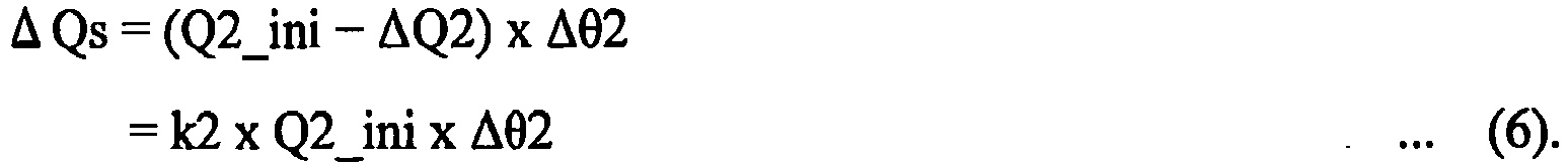
- When the rechargeable lithium ion battery is in the initial state, the positive electrode's composition θ4fix_ini corresponds to the negative electrode's composition θ2fix_ini. When the rechargeable lithium ion battery is in a degraded state, the positive electrode's composition θ1fix corresponds to the negative electrode's composition θ2fix. Furthermore, the deviation of the correspondence in composition is with reference to the positive electrode's composition θ1fix in the initial state. That is, the positive electrode's compositions θ1fix and θ1fix_ini are equal in value.
- When the rechargeable lithium ion battery's degradation results in the positive and negative electrodes having their respective compositions having a correspondence with a deviation, the rechargeable lithium ion battery degraded has the positive and negative electrodes with their respective compositions θ1fix and 02fix having a relationship of the following expressions (7) and (8):


- Expression (8) has a meaning, as described hereinafter. When the rechargeable lithium ion battery degrades, and accordingly, the positive electrode's composition θ1 varies (or is reduced) from 1 to θ1 fix, the positive electrode discharges lithium in an amount represented by the following expression (9):
- The positive electrode discharges lithium in an amount

- Herein, 1 - θ1fix has a value indicating how much the positive electrode's composition varies as the rechargeable lithium ion battery is degraded, and k1 x Q1_ini has a value indicating the positive electrode's capacity after the rechargeable lithium ion battery is degraded.
- If the lithium discharged from the positive electrode is all taken into the negative electrode, then the negative electrode's composition θ2fix will be represented by the following expression (10):

- Herein, k2 x Q2_ini has a value representing the negative electrode's capacity after the rechargeable lithium ion battery is degraded.
- On the other hand, when the positive and negative electrodes have compositions, respectively, having a correspondence with a deviation (Δθ2) then the negative electrode's composition θ2fix is represented by the following expression (11):

- The amount of deviation Δθ2 of the correspondence in composition can be represented by expression (6), using deviated capacity ΔQs of the correspondence in composition. Thus the negative electrode's composition θ2fix is represented by the above expression (8).
- As shown in
Fig. 12 , when the rechargeable lithium ion battery is in a degraded state, open circuit voltage OCV is represented as a potential difference between the positive electrode's open circuitpotential U 11 and the negative electrode's open circuit potential U22 in the degraded state. That is, estimating three degradation parameters k1, k2, ΔQs allows the negative electrode's open circuit potential U22 with the rechargeable lithium ion battery in a degraded state to be determined, and open circuit voltage OCV can be calculated as a potential difference between the negative electrode's open circuit potential U22 and the positive electrode's open circuit potential U11. - Furthermore, in the present embodiment, degradation parameters k1, k2, and ΔQs are used to estimate the rechargeable lithium ion battery's internal state, more specifically, whether the rechargeable lithium ion battery is degraded as lithium deposits. Generally, a rechargeable lithium ion battery's degradation includes that attributed to deposition of lithium and that attributed to wear, and distinguishing these types of degradation and thus determining (or estimating) them allows a state of degradation to be determined in detail.
- Degradation attributed to wear is a type of degradation of the rechargeable lithium ion battery excluding degradation attributed to deposition of lithium, and means that as the battery electrically conducts or is left or the like its positive and negative electrodes' performance (or ability to accept lithium) is impaired. For example, it includes, as one example, that the positive/negative electrodes have their active materials worn. On the other hand, degradation attributed to deposition of lithium indicates that the lithium ions used for a battery's reaction change into a byproduct (mainly, metallic lithium), and thus no longer contribute to cell reaction.
- When the rechargeable lithium ion battery is not degraded, open circuit voltage OCV will coincide with that of the rechargeable lithium ion battery in the initial state. That is, when the positive electrode's capacity ratio k1 and the negative electrode's capacity ratio k2 are 1 and deviated capacity ΔQs of the correspondence in composition is 0, open circuit voltage OCV calculated (or estimated) as described above will coincide with a value of open circuit voltage OCV (as measured) that is obtained when the rechargeable lithium ion battery is in the initial state (or unused).
-
Fig. 13 shows a relationship between the rechargeable lithium ion battery's capacity (SOC) and open circuit voltage OCV (i.e., an open circuit voltage characteristic). Hereinafter, a curve shown inFig. 13 and the like that represents an open circuit voltage characteristic will also be referred to as an "open circuit voltage curve." InFig. 13 , a dotted line indicates an open circuit voltage curve (as measured), and a solid line indicates an open circuit voltage curve (as estimated). The open circuit voltage curve (as estimated) overlaps the open circuit voltage curve (as measured). - In
Fig. 13 , the axis of ordinate represents open circuit voltage OCV, and the axis of abscissa represents the rechargeable lithium ion battery's capacity. - When the rechargeable lithium ion battery degrades, open circuit voltage (as measured) OCV will vary. Herein,
Fig. 14 (a figure corresponding toFig. 13 ) shows a dotted line, which indicates a result of having measured an open circuit voltage curve (as measured) of a rechargeable lithium ion battery degraded only by deposition of lithium, that is, a rechargeable lithium ion battery free of degradation attributed to wear. - If the rechargeable lithium ion battery is held at low temperature, degradation attributed to wear can be suppressed, and this allows deposition of lithium to be alone caused while degradation attributed to wear is suppressed. By conducting an experiment of whether degradation attributed to wear is caused under a plurality of temperature conditions, a temperature set to set the rechargeable lithium ion battery at low temperature can be determined. This allows degradation attributed to deposition of lithium to be alone caused in the rechargeable lithium ion battery.
- Correctly estimating the three degradation parameters (k1, k2, ΔQs) allows an open circuit voltage curve (as estimated) to substantially coincide with the open circuit voltage curve (as measured) represented in
Fig. 14 . In other words, the three degradation parameters can be searched for to cause the open circuit voltage curve (as estimated) to substantially coincide with the open circuit voltage curve (as measured). -
Fig. 14 represents open circuit voltage (as measured) OCV and open circuit voltage (as estimated) OCV substantially coinciding with each other. This open circuit voltage curve (as estimated) is determined with degradation parameters as follows: the positive electrode's capacity ratio k1 of 1; the negative electrode's capacity ratio k2 of 1; and the compositions having a correspondence with deviated capacity ΔQs of 0.62. These degradation parameter values can be obtained by searching for and obtaining the three degradation parameters (k1, k2, ΔQs) allowing the open circuit voltage curve (as estimated) to substantially coincide with the open circuit voltage curve (as measured) represented inFig. 14 . -
Fig. 15 indicates a result of having measured an open circuit voltage curve (as measured) of a rechargeable lithium ion battery degraded by wear alone, that is, a rechargeable lithium ion battery which does not have lithium deposited therein. InFig. 15 , the axis of ordinate represents open circuit voltage OCV, and the axis of abscissa represents the rechargeable lithium ion battery's capacity. - If the rechargeable lithium ion battery is held at high temperature, deposition of lithium can be suppressed, and this allows degradation attributed to wear to be alone caused while deposition of lithium is suppressed. By conducting an experiment of whether lithium deposits under a plurality of temperature conditions, a temperature set to set the rechargeable lithium ion battery at high temperature can be determined. The temperature set can be 50°C, for example. This allows degradation attributed to wear to be alone caused in the rechargeable lithium ion battery.
-
Fig. 15 represents open circuit voltage (as measured) OCV and open circuit voltage (as estimated) OCV substantially coinciding with each other. At the time, an open circuit voltage curve (as estimated) is determined with degradation parameters as follows: the positive electrode's capacity ratio k1 of 0.85; the negative electrode's capacity ratio k2 of 0.97; and the compositions having a correspondence with deviated capacity ΔQs of 0.05. These degradation parameter values can be obtained by searching for and obtaining the three degradation parameters (k1, k2, ΔQs) allowing the open circuit voltage curve (as estimated) to substantially coincide with the open circuit voltage curve (as measured) represented inFig. 15 . - As shown in
Fig. 14 andFig. 15 , it can be seen that the rechargeable lithium ion battery that is degraded only by deposition of lithium has only one of the three degradation parameters (k1, k2, ΔQs), i.e., deviated capacity ΔQs of the correspondence in composition, varied from ΔQs (= 0) of the rechargeable lithium ion battery unused (or in the initial state). - Furthermore, it can be seen that the rechargeable lithium ion battery degraded only by wear has the three degradation parameters (k1, k2, ΔQs) all deviating from those of the rechargeable lithium ion battery unused (or in the initial state). Note that degradation attributed to wear provides the compositions with a correspondence therebetween having a deviated capacity ΔQs smaller than degradation attributed to deposition of lithium does.
- Lithium may deposit because, for example, lithium ions discharged from the positive electrode in electrically charging the battery may not be taken into the negative electrode. In that case, the positive electrode and the negative electrode will have their compositions with a correspondence having a deviation, and deviated capacity ΔQs will vary. Furthermore, deposition of lithium caused alone does not impair the positive and negative electrodes' ability to accept lithium, and accordingly, the positive electrode's capacity ratio k1 and the negative electrode's capacity ratio k2 will each be held at 1.
- Thus, deviated capacity ΔQs includes a deviated capacity ΔQs(Li) resulting from degradation attributed to deposition of lithium, and a deviated capacity ΔQs(W) resulting from degradation attributed to wear, and accordingly, separating one from the other allows quantitative estimation of an amount of lithium deposited.
- Initially, a map used to identify a component of degradation that is attributed to wear will be described. This map represents a correspondence between the positive and negative electrodes' capacity ratios k1 and k2 and deviated capacity ΔQs of a correspondence in composition when the rechargeable lithium ion battery is degraded by wear alone. The map can be previously created based on a result of an experiment. As has been set forth above, holding the rechargeable lithium ion battery at high temperature can prevent deposition of lithium, and thus allows an experiment to be conducted to cause degradation attributed to wear alone.
- Degradation attributed to wear is gradually advanced to decrease the rechargeable lithium ion battery's capacity (i.e., full charge capacity) gradually by a predetermined amount. Whenever the rechargeable lithium ion battery's capacity is decreased, the rechargeable lithium ion battery's open circuit voltage OCV is measured. This allows data to be obtained that indicates how the rechargeable lithium ion battery varies in open circuit voltage OCV as the rechargeable lithium ion battery varies in capacity when the rechargeable lithium ion battery has its capacity degraded as prescribed (i.e., an open circuit voltage curve (as measured)). For example, until the rechargeable lithium ion battery has a capacity reaching from 100% to 50%, the capacity is decreased (or degraded) by 5% at a time, and whenever the capacity is decreased, the rechargeable lithium ion battery's open circuit voltage OCV is measured.
- Then, the degradation parameters (the positive electrode's capacity ratio k1, the negative electrode's capacity ratio k2, and deviated capacity ΔQs) can be searched for for causing open circuit voltage (as estimated) OCV to coincide with open circuit voltage (as measured) OCV obtained for each capacity degradation.
- Thus, the map (hereinafter also referred to as a map for degradation attributed to wear) shown in
Fig. 16 can be obtained. TheFig. 16 map shows a correspondence between the positive and negative electrodes' capacity ratios k1 and k2 and deviated capacity ΔQs(W), and for example, the positive electrode's capacity ratio k1 and the negative electrode's capacity ratio k2 can be selected to determine deviated capacity ΔQs(W) resulting from degradation attributed to wear. The map can be stored in a memory. - Note that in the present embodiment, obtaining data indicating how
battery module 10 orbattery cell 20 varies in open circuit voltage (as measured) OCV as it varies in capacity (i.e., an open circuit voltage curve), as shown inFig. 13 to Fig. 15 , allows degradation parameters (k1, k2, ΔQs) to be searched for so that open circuit voltage (as estimated) OCV may coincide with open circuit voltage (as measured) OCV. - An open circuit voltage curve can be obtained through electrically charging/discharging
battery module 10 or battery cell 20 (or a rechargeable lithium ion battery) that has completely been used off board. It should be noted that the open circuit voltage curve can also be measured on board while the rechargeable lithium ion battery is in use. For example, it can also be measured byECU 120 for each battery block on board whilebattery module 10 is in use. For example, when the rechargeable lithium ion battery is relaxed (or a state with the battery's current = 0 continues), the battery's voltage can be sensed and how the battery's open circuit voltage varies can be measured therefrom, and the battery's current Ib can be integrated, and from the integral, how the battery's capacity varies can be measured. -
Fig. 17 is a flowchart showing a controlling process procedure performed byMPU 131 for obtaining a degradation parameter of a rechargeable lithium ion battery bybattery checker 130 off board. - With reference to
Fig. 17 ,MPU 131 at Step S 151 measures open circuit voltage (as measured) OCV of the rechargeable lithium ion battery (battery module 10 or battery cell 20) subject to determination of whether it is degraded, based on an output ofvoltage sensor 15b. Specifically, measuring open circuit voltage (as measured) OCV while electrically charging/discharging the rechargeable lithium ion battery allows an open circuit voltage curve (as measured) to be obtained. -
MPU 131 atStep S 152 appropriately modifies three degradation parameters (the positive electrode's capacity ratio k1, the negative electrode's capacity ratio k2, and deviated capacity ΔQs) and thus determines whether open circuit voltage (as estimated) OCV determined by the three degradation parameters coincides with open circuit voltage (as measured) OCV obtained at Step S151. - As shown in
Fig. 18 , specifically, the three degradation parameters are set in any combination and thus used to calculate open circuit voltage (as estimated) OCV.Fig. 18 shows an example of a relationship between open circuit voltage (as estimated) OCV represented by a dotted line and open circuit voltage (as measured) OCV represented by a solid line. - In
Fig. 18 , when an open circuit voltage curve of an estimatedvalue 1 is obtained, open circuit voltage (as estimated) OCV is higher than open circuit voltage (as measured) OCV, and accordingly, the degradation parameters are re-set to approach the open circuit voltage curve as measured. Similarly, when an open circuit voltage curve of an estimatedvalue 2 is obtained, open circuit voltage (as estimated) OCV is lower than open circuit voltage (as measured) OCV, and accordingly, the degradation parameters are re-set to approach the open circuit voltage curve as measured. Thus, the degradation parameters can repeatedly be re-set to allow open circuit voltage (as estimated) OCV to coincide with open circuit voltage (as measured) OCV. - Again with reference to
Fig. 17 ,MPU 131 atStep S 152 determines the degradation parameters when open circuit voltage (as estimated) OCV coincides with open circuit voltage (as measured) OCV. The positive electrode's capacity ratio k1, the negative electrode's capacity ratio k2, and deviated capacity ΔQs are thus determined. Note that deviated capacity ΔQs determined at Step S152 is a deviated capacity including both a deviated capacity resulting from degradation attributed to deposition of lithium and a deviated capacity resulting from degradation attributed to wear. - If open circuit voltage (as estimated) OCV does not completely coincide with open circuit voltage (as measured) OCV, setting a range in which they are regarded as coinciding with each other (i.e., a tolerable error) allows whether open circuit voltage (as estimated) OCV and open circuit voltage (as measured) OCV coincide with each other to be determined.
-
MPU 131 at Step S 153 uses the positive and negative electrodes' capacity ratios k1 and k2 determined at Step S152 and the map for degradation attributed to wear (seeFig. 16 ) to determine deviated capacity ΔQs(W). Furthermore,MPU 131 at Step S 154 obtains a difference between deviated capacity ΔQs obtained atStep S 152 and deviated capacity ΔQs(W) obtained at Step S153. This calculates deviated capacity ΔQs(Li) resulting from degradation attributed to deposition of lithium. - Thus an open circuit voltage characteristic of the rechargeable lithium ion battery (
battery module 10 or battery cell 20) can be measured off board to obtain degradation parameters, or the positive electrode's capacity ratio k1, the negative electrode's capacity ratio k2, and deviated capacity ΔQs. Furthermore, deviated capacity ΔQs can be separated into deviated capacity ΔQs(W) resulting from degradation attributed to wear and deviated capacity ΔQs(Li) resulting from degradation attributed to deposition of lithium to allow deposition of lithium to be quantitatively estimated without disassembling the rechargeable lithium ion battery and conducting a chemical analysis. - Again with reference to
Fig. 8 , lithiumdeposition measurement unit 170 measures through the above described degradation diagnosis deviated capacity ΔQs (Li) resulting from degradation attributed to deposition of lithium as a parameter representing an amount of lithium deposited. Lithiumdeposition measurement unit 170 can measure parameter ΔQs (Li) either before or after re-restraint through a charging and discharging test usingbattery checker 130. In other words, lithiumdeposition measurement unit 170 corresponds to a "first measurement unit" if it measures the full charge capacity after re-restraint, and lithiumdeposition measurement unit 170 corresponds to a "second measurement unit" if it measures the full charge capacity before re-restraint. -
Evaluation unit 190 reflects battery parameter ΔQs(Li) representing an amount of lithium deposited to generate value information ofbattery module 10 reused. - Thus according to the second embodiment of the present invention an amount of lithium deposited, which has a large effect on the rechargeable lithium ion battery in performance (or life expectancy), can further be reflected to more accurately calculate a value of
battery module 10 reused. - The second embodiment in an exemplary variation provides the process that has been described in the second embodiment (see
Fig. 17 ) on board. For example a process similar to that of the second embodiment is performed by a controller (ECU 120) controlling electrically charging/discharging a rechargeable lithium ion battery mounted in an electrically powered vehicle. An electrically powered vehicle which can electrically charge an in-vehicle battery (a rechargeable lithium ion battery) from a power supply external to the vehicle, is used. Such a vehicle includes a plug-in hybrid vehicle (PHV) and an electric vehicle (EV). -
Fig. 19 is a flowchart showing a procedure of a controlling process for obtaining a degradation parameter of a rechargeable lithium ion battery that is mounted in a vehicle on board. TheFig. 19 process is performed by a controller (ECU 120 indicated inFig. 2 for example) mounted in a vehicle. -
ECU 120 at Step S201 measures open circuit voltage (as measured) OCV of the rechargeable lithium ion battery (battery module 10) and an amount of a current accumulated of the battery, as based on an output of the voltage sensor and that of the current sensor that are included inbattery sensor 15. Specifically, when the rechargeable lithium ion battery mounted in a vehicle is electrically charged, open circuit voltage (as measured) OCV and an amount of a current accumulated are measured, as appropriate, and a curve can thus be obtained that indicates how the battery's open circuit voltage (as measured) OCV varies as its capacity varies (i.e., an open circuit voltage curve as a measured value). -
ECU 120 at Step S202 sets (or selects) candidates for degradation parameters (i.e., the positive electrode's capacity ratio k1, the negative electrode's capacity ratio k2, and deviated capacity ΔQs) for determining open circuit voltage (as estimated) OCV. While the degradation parameters can be set in various methods, preferably, a method is selected for efficiently performing an operation process for setting the degradation parameters. - For example, a degradation parameter may be selected within a range which is previously determined through an experiment or the like and in which degradation attributed to wear and degradation attributed to deposition of lithium are actually caused. Note that the positive electrode's capacity ratio k1 and the negative electrode's capacity ratio k2 depend solely on degradation attributed to wear, and accordingly, the positive electrode's capacity ratio k1 and the negative electrode's capacity ratio k2 can be varied within a range within which degradation attributed to wear is actually caused. Once the positive electrode's capacity ratio k1 and the negative electrode's capacity ratio k2 have been determined, the map for degradation attributed to wear (
Fig. 16 ) can be used to determine deviated capacity AQs(W) resulting from degradation attributed to wear. Once deviated capacity ΔQs(W) has been determined, what is necessary is simply to vary deviated capacity ΔQs(Li). - Then,
ECU 120 at Step S203 uses the degradation parameters set at Step S202 to calculate a characteristic indicating how open circuit voltage (as estimated) OCV varies as the capacity varies (i.e., an open circuit voltage curve as an estimated value). -
ECU 120 at Step S204 calculates an error between the open circuit voltage curve (as estimated) calculated at Step S203 and the open circuit voltage curve (as measured) obtained at Step S201. This error includes a voltage error and a capacity error. - A voltage error ΔV (see
Fig. 20 ) can be calculated specifically by comparing the open circuit voltage curve (as estimated) and the open circuit voltage curve (as measured). Voltage error ΔV may be a voltage error in a specific battery capacity, or may be an average of voltage errors between two open circuit voltage curves. - Furthermore, a capacity error ΔQ can be obtained for example in a method described hereinafter. Initially, the open circuit voltage curve (as estimated) is used to calculate a capacity Q1 between an open circuit voltage before the battery is electrically charged and an open circuit voltage after the battery is electrically charged. Furthermore, after electrically charging the battery is started before doing so ends, a current is sensed and accumulated in value, and a charged capacity Q2 can be calculated therefrom. By obtaining a difference between capacity Q1 and capacity Q2, an absolute value of capacity error ΔQ (|Q1 - Q2|) can be obtained.
- Note that it is difficult to obtain an open circuit voltage curve (as measured) for a hybrid vehicle which is not equipped with a charger by an external power supply. However, when the rechargeable lithium ion battery is relaxed, some open circuit voltages located on the open circuit voltage curve (as measured) can be measured. Note that when the rechargeable lithium ion battery passes a current or immediately after it has a current interrupted or the like, there is a difference in concentration of lithium in the active material and open circuit voltage cannot be measured accurately.
- On the other hand, once time has elapsed after the rechargeable lithium ion battery was interrupted from electrical conduction, the rechargeable lithium ion battery will be relaxed, and accordingly there is no difference in concentration of lithium and open circuit voltage can accurately be measured. The rechargeable lithium ion battery is relaxed for example when a vehicle is stopped beyond a predetermined period of time. Thus, open circuit voltage (as measured) OCV of the rechargeable lithium ion battery for when the battery has a specific capacity can be obtained.
- The specific open circuit voltage measured for the specific capacity allows an open circuit voltage (as measured) to be compared with an open circuit voltage curve (as estimated) to obtain voltage error ΔV, as shown in
Fig. 21 . Furthermore, if a plurality of open circuit voltages (as measured) are measured, capacity error ΔQ can be obtained as described above. Specifically, an open circuit voltage curve (as estimated) is used to calculate capacity Q1 between open circuit voltages of two points (as measured). Furthermore, measuring a value of an accumulated current when the open circuit voltages (as measured) of the two points are obtained allows the value to be used to calculate capacity Q2. Then, a difference of capacity Q1 and capacity Q2 (|Q1 - Q2|) can be calculated to obtain an absolute value of capacity error ΔQ. -
ECU 120 at Step S205 calculates an evaluation function f (ΔV, ΔQ) for voltage error ΔV and capacity error ΔQ obtained at Step S204. As evaluation function f (ΔV, ΔQ), voltage error ΔV and capacity error ΔQ with a weight added thereto can be used. - Furthermore,
ECU 120 determines whether evaluation function f (ΔV, ΔQ) calculated from the currently set degradation parameters is smaller than evaluation function f (ΔV, ΔQ) calculated from the immediately previously set degradation parameters. Herein, if the current evaluation function f (ΔV, ΔQ) is smaller than the immediately previous evaluation function f (ΔV, ΔQ), the former is stored to a memory. If the current evaluation function f (ΔV, ΔQ) is larger than the immediately previous evaluation function f (ΔV, ΔQ), the latter will remain stored in the memory. -
ECU 120 at Step S206 determines whether each degradation parameter has been varied throughout a search range, and if so,ECU 120 proceeds to Step S207. Otherwise,ECU 120 returns to Step S202. - Thus, Steps S202-S206 are repeated until each degradation parameter has been varied throughout the search range. Then, evaluation function f (ΔV, ΔQ) that serves as a minimum value is determined and an open circuit voltage curve for which this evaluation function (or the minimum value) is obtained can be determined, and the degradation parameters (k1, k2, ΔQs) defining an open circuit voltage curve (as estimated) can be determined. Determining degradation parameters allowing an evaluation function to indicate a minimum value allows a degraded state (i.e., degradation attributed to wear and degradation attributed to deposition of lithium) to be determined more precisely.
- Herein, deviated capacity ΔQs that is determined includes deviated capacity ΔQs(W) by degradation attributed to wear, and deviated capacity ΔQs(Li) by degradation attributed to deposition of lithium. Accordingly,
ECU 120 at Step S207 uses degradation parameters determined through Steps S202-S206 (i.e., the positive electrode's capacity ratio k1 and the negative electrode's capacity ratio k2) and the map for degradation attributed to wear (seeFig. 10 ) to determine deviated capacity ΔQs(W) resulting from degradation attributed to wear. Then,ECU 120 at Step S208 calculates a difference between deviated capacity ΔQs determined through Steps S202-S206 and deviated capacity AQs(W) obtained at Step S207 to calculate deviated capacity ΔQs(Li) attributed to deposition of lithium. - Thus the second embodiment in the exemplary variation allows a rechargeable lithium ion battery mounted in an electrically powered vehicle to be diagnosed for degradation, as based on an open circuit voltage characteristic, to obtain a positive electrode's capacity ratio k1, a negative electrode's capacity ratio k2, and deviated capacity ΔQs on board. In particular, for both a PHV and an EV having a function using a power supply external to the vehicle to externally electrically charge an in-vehicle battery, and a hybrid vehicle which is not equipped with the function, a degradation parameter can be obtained on board, based on an open circuit voltage characteristic, and parameter ΔQs (Li) representing an amount of lithium deposited can also be measured.
- In the second embodiment in the exemplary variation, lithium
deposition measurement unit 170 ofFig. 8 can obtain parameter ΔQs (Li) through data communication betweenbattery checker 130 andECU 120. The remaining operation is similar to that in the second embodiment, and accordingly, will not be described repeatedly in detail. - Thus according to the second embodiment in the exemplary variation a battery parameter indicating an amount of lithium deposited, which has a large effect on the rechargeable lithium ion battery in performance (or life expectancy), can be obtained without
battery checker 130 performing measurement off board. This can reduce a period of time required to calculate a value ofbattery module 10 reused, as compared with the second embodiment. - As has been described in the second embodiment and its exemplary variation, battery parameter ΔQs (Li) can be obtained off board or on board, and thus measured as timed as desired.
- How lithium deposits in a rechargeable lithium ion battery, however, may vary depending on environmental conditions. For example, it is known that
battery cell 20 left at high temperature for a long period of time has lithium deposited in a reduced amount. Accordingly, if possible, battery parameter ΔQs (Li) is measured before or after the re-restraint step (theFig. 6 Step S130), preferably after re-restraint. - Note that while the second embodiment and its exemplary variation have been described such that a rechargeable battery (a rechargeable lithium ion battery) subject to determination of degradation is a rechargeable battery mounted in an electrically powered vehicle, the present invention is not limited thereto. That is, the present value calculation technique is applicable to reusing a rechargeable battery that is used with a plurality of battery cells restrained by a restraint member.
- Furthermore, while the present embodiment has been described with a battery parameter exemplified by full charge capacity, internal resistance, and amount of lithium deposited, other battery parameters can also be adopted to calculate a value of a rechargeable battery in accordance with the present invention. For example, as a known parameter, a diffusion coefficient Ds of a reaction-participating material (such as lithium in a rechargeable lithium ion battery) described in Japanese Patent Laying-Open No.
2008-241246 - The present invention is applicable to a technique for reusing a rechargeable battery that is used as a battery pack with a plurality of battery cells restrained by a restraint member.
- 10: battery module; 11: positive electrode terminal; 12: negative terminal; 15: battery sensor; 15a: current sensor; 15b: voltage sensor; 15c: temperature sensor; 17: opening; 20: battery cell; 21: electrode; 30: emission gas flow path unit; 31: exhaust tube; 40: end plate; 41: battery holder; 42: restraint band; 45: rivet; 83: horizontal direction; 89: direction in which battery cells are stacked; 120: ECU; 130: battery checker; 131: MPU; 132: memory; 133: communication device; 135, 136: test terminal; 137, 138: switch; 150: capacity data measurement unit; 160: internal resistance measurement unit; 170: lithium deposition measurement unit; 190: evaluation unit; 200: power supply; 210: load; Ib: battery current; OCV: open circuit voltage; Q1, Q2: charged capacity; Rp: internal resistance; TC: full charge capacity; U1, U2: open circuit potential; Vb: battery voltage; k1: positive electrode's capacity ratio; k2: negative electrode's capacity ratio; ΔQs: battery capacity fluctuation amount (deviated capacity); ΔQs (Li): deviated capacity (resulting from deposition of lithium); ΔQs (W): deviated capacity (resulting from degradation attributed to wear).
Claims (4)
- A value calculation method for calculating a value of a rechargeable battery (10) in a re-restrained state for pricing the re-restrained rechargeable battery (10), the rechargeable battery (10) having a plurality of battery cells (20) restrained by a restraint member (42), the method comprising the steps of:removing the restraint member (42) from the rechargeable battery (10) and disassembling the rechargeable battery (10); thereafterreplacing one or more degraded battery cells (20); thereafterre-assembling and re-restraining the rechargeable battery (10) with the restraint member (42); thereafterdetecting (S140) battery data as said rechargeable battery (10) is electrically charged and discharged;measuring (S150) a battery parameter of said rechargeable battery (10) based on said battery data; andevaluating (S160) a value of said re-restrained rechargeable battery (10) reused, said evaluating being based on said battery parameter measured in the step of measuring,said battery parameter at least including an internal resistance of said rechargeable battery (10).
- The value calculation method according to claim 1, further comprising the step of measuring (S100) said battery parameter of one of said rechargeable battery (10) and said battery cells (20) before said rechargeable battery (10) is re-restrained, said measuring being based on said battery data detected before said rechargeable battery (10) is re-restrained, wherein:said battery parameter includes a first parameter measured in the step of measuring after said rechargeable battery (10) is re-restrained and a second parameter measured in the step of measuring before said rechargeable battery (10) is re-restrained;said first parameter includes said internal resistance; andsaid second parameter includes a full charge capacity of said rechargeable battery (10).
- The value calculation method according to claim 1 or 2, wherein:said rechargeable battery (10) is a rechargeable lithium ion battery;the step of measuring (S150) after said rechargeable battery is re-restrained includes the steps ofperforming (S151, S152) a degradation diagnosis based on an open circuit voltage characteristic of said rechargeable lithium ion battery indicating how said rechargeable lithium ion battery varies in open circuit voltage as said rechargeable lithium ion battery varies in capacity to obtain a capacity ratio (k1) of a positive electrode of said rechargeable lithium ion battery, a capacity ratio (k2) of a negative electrode of said rechargeable lithium ion battery, and a battery capacity fluctuation amount (ΔQs), andapplying (S153, S154) said capacity ratios respectively of said positive and negative electrodes that are obtained to a previously obtained correspondence between said capacity ratios respectively of said positive and negative electrodes and a first amount (ΔQs(W)) of said battery capacity fluctuation amount to separate said battery capacity fluctuation amount that is obtained into said first amount and a second amount (ΔQs(Li)) of said battery capacity fluctuation amount, said first amount (ΔQs(W)) corresponding to degradation attributed to wear, said second amount (ΔQs(Li)) corresponding to degradation attributed to deposition of lithium; andone of said battery parameter and said first parameter includes said second amount.
- The value calculation method according to claim 2, wherein:said rechargeable battery (10) is a rechargeable lithium ion battery;the step of measuring (S100) before said rechargeable battery is re-restrained includes the steps ofperforming (S141, S142) a degradation diagnosis based on an open circuit voltage characteristic of said rechargeable lithium ion battery indicating how said rechargeable lithium ion battery varies in open circuit voltage as said rechargeable lithium ion battery varies in capacity to obtain a capacity ratio (k1) of a positive electrode of said rechargeable lithium ion battery, a capacity ratio (k2) of a negative electrode of said rechargeable lithium ion battery, and a battery capacity fluctuation amount (ΔQs) andapplying (S143, S144) said capacity ratios respectively of said positive and negative electrodes that are obtained to a previously obtained correspondence between said capacity ratios respectively of said positive and negative electrodes and a first amount (ΔQs(W)) of said battery capacity fluctuation amount to separate said battery capacity fluctuation amount that is obtained into said first amount and a second amount (ΔQs(Li)) of said battery capacity fluctuation amount, said first amount (ΔQs(W)) corresponding to degradation attributed to wear, said second amount (ΔQs(Li)) corresponding to degradation attributed to deposition of lithium; andsaid second parameter includes said second amount.
Applications Claiming Priority (1)
| Application Number | Priority Date | Filing Date | Title |
|---|---|---|---|
| PCT/JP2010/058268 WO2011145161A1 (en) | 2010-05-17 | 2010-05-17 | Value calculation device and value calculation method for secondary battery |
Publications (3)
| Publication Number | Publication Date |
|---|---|
| EP2573859A1 EP2573859A1 (en) | 2013-03-27 |
| EP2573859A4 EP2573859A4 (en) | 2014-03-12 |
| EP2573859B1 true EP2573859B1 (en) | 2015-10-28 |
Family
ID=44991288
Family Applications (1)
| Application Number | Title | Priority Date | Filing Date |
|---|---|---|---|
| EP10851725.1A Active EP2573859B1 (en) | 2010-05-17 | 2010-05-17 | Device and method for calculating a value of a rechargeable battery |
Country Status (5)
| Country | Link |
|---|---|
| US (1) | US8836284B2 (en) |
| EP (1) | EP2573859B1 (en) |
| JP (1) | JP5435128B2 (en) |
| CN (1) | CN102939683B (en) |
| WO (1) | WO2011145161A1 (en) |
Families Citing this family (27)
| Publication number | Priority date | Publication date | Assignee | Title |
|---|---|---|---|---|
| JP5341823B2 (en) * | 2010-06-07 | 2013-11-13 | トヨタ自動車株式会社 | Lithium ion secondary battery degradation judgment system and degradation judgment method |
| US9337668B2 (en) | 2011-04-28 | 2016-05-10 | Zoll Circulation, Inc. | Viral distribution of battery management parameters |
| US9197079B2 (en) | 2011-04-28 | 2015-11-24 | Zoll Circulation, Inc. | System and method for tracking and archiving battery performance data |
| CN104204829B (en) * | 2012-04-19 | 2016-08-24 | 丰田自动车株式会社 | The inspection device of all-solid-state battery and inspection method |
| JP5768001B2 (en) * | 2012-04-23 | 2015-08-26 | 株式会社日立製作所 | Battery system maintenance management system and method |
| JP5768763B2 (en) * | 2012-05-30 | 2015-08-26 | トヨタ自動車株式会社 | Battery system |
| JP5596083B2 (en) * | 2012-06-26 | 2014-09-24 | Imv株式会社 | Lithium-ion secondary battery deterioration diagnosis device |
| JP6225340B2 (en) * | 2013-10-29 | 2017-11-08 | パナソニックIpマネジメント株式会社 | Battery state estimation device |
| JP2015191878A (en) * | 2014-03-31 | 2015-11-02 | 株式会社日立製作所 | Lithium ion secondary battery system and method for diagnosing state of lithium ion secondary battery |
| US10288691B2 (en) * | 2014-06-05 | 2019-05-14 | Ford Global Technologies, Llc | Method and system for estimating battery model parameters to update battery models used for controls |
| WO2016002398A1 (en) * | 2014-07-01 | 2016-01-07 | 日産自動車株式会社 | Battery degradation level estimation device and battery degradation level estimation method |
| JP6225924B2 (en) * | 2015-01-13 | 2017-11-08 | トヨタ自動車株式会社 | Secondary battery inspection method |
| US9800071B2 (en) * | 2015-02-24 | 2017-10-24 | Green Cubes Technology Corporation | Methods and system for add-on battery |
| KR101684092B1 (en) * | 2015-04-08 | 2016-12-07 | 현대자동차주식회사 | Apparatus and Method for caculating degradation degree |
| ITUB20152010A1 (en) * | 2015-07-09 | 2017-01-09 | Magneti Marelli Spa | Electronic battery pack control device for vehicle and system using this device |
| JP6485346B2 (en) * | 2015-12-24 | 2019-03-20 | トヨタ自動車株式会社 | Processing method for reusing secondary batteries |
| US10183588B2 (en) | 2016-01-06 | 2019-01-22 | Johnson Controls Technology Company | Battery module lithium plating reduction |
| JP6485708B2 (en) * | 2016-01-13 | 2019-03-20 | トヨタ自動車株式会社 | Battery system |
| JP6555212B2 (en) * | 2016-08-15 | 2019-08-07 | トヨタ自動車株式会社 | Battery pack manufacturing method |
| KR102258833B1 (en) * | 2017-09-28 | 2021-05-31 | 주식회사 엘지에너지솔루션 | Apparatus for acquiring degradation information of a lithium ion battery cell |
| CN109450051B (en) * | 2018-12-30 | 2022-05-10 | 宁波达航数据技术有限公司 | Battery system and control method thereof |
| US10511050B1 (en) * | 2018-12-31 | 2019-12-17 | Sf Motors, Inc. | Battery state of health estimation by tracking electrode and cyclable lithium capacities |
| CN112379293B (en) * | 2019-06-24 | 2022-09-23 | 宁德时代新能源科技股份有限公司 | Charge state correction method and device |
| US11214171B2 (en) * | 2019-09-13 | 2022-01-04 | Ford Global Technologies, Llc | Mixed battery pack control |
| JP7012701B2 (en) * | 2019-12-23 | 2022-01-28 | 本田技研工業株式会社 | Combination determination device, combination determination method, and program |
| JP7443821B2 (en) | 2020-02-28 | 2024-03-06 | 株式会社デンソー | Information calculation system |
| GB2623768B (en) * | 2022-10-25 | 2024-11-13 | Autocraft Solutions Group Ltd | Method and system for determining reusability of a battery |
Family Cites Families (19)
| Publication number | Priority date | Publication date | Assignee | Title |
|---|---|---|---|---|
| JP3750318B2 (en) * | 1997-11-14 | 2006-03-01 | 日産自動車株式会社 | Module charger / discharger |
| JP4001708B2 (en) * | 2000-04-28 | 2007-10-31 | 松下電器産業株式会社 | Replacing the secondary battery |
| JP4134704B2 (en) * | 2002-12-02 | 2008-08-20 | トヨタ自動車株式会社 | Replacing the secondary battery |
| EP2613165B1 (en) * | 2003-06-27 | 2014-09-24 | The Furukawa Electric Co., Ltd. | Method and device for measuring secondary cell internal impedance |
| US7616002B2 (en) * | 2003-12-30 | 2009-11-10 | Batterycorp, Inc. | Battery management system and apparatus with anomaly reporting |
| JP4655568B2 (en) | 2004-05-25 | 2011-03-23 | トヨタ自動車株式会社 | Secondary battery state estimation method and system |
| JP4710325B2 (en) | 2005-01-17 | 2011-06-29 | トヨタ自動車株式会社 | Mobile pricing system and pricing method |
| KR100684764B1 (en) * | 2005-07-29 | 2007-02-20 | 삼성에스디아이 주식회사 | Secondary battery module and connecting rod for fixing unit battery |
| US7964299B2 (en) * | 2005-10-18 | 2011-06-21 | Enerdel, Inc. | Method of recycling a battery |
| JP5039980B2 (en) * | 2005-11-14 | 2012-10-03 | 日立ビークルエナジー株式会社 | Secondary battery module |
| JP4797640B2 (en) | 2006-01-18 | 2011-10-19 | トヨタ自動車株式会社 | Secondary battery life estimation device |
| JP4577274B2 (en) * | 2006-06-06 | 2010-11-10 | 株式会社デンソー | Vehicle power supply system |
| JP4703593B2 (en) | 2007-03-23 | 2011-06-15 | 株式会社豊田中央研究所 | Secondary battery state estimation device |
| JP5319081B2 (en) * | 2007-05-22 | 2013-10-16 | プライムアースEvエナジー株式会社 | Manufacturing method of battery pack with controller |
| JP4649682B2 (en) * | 2008-09-02 | 2011-03-16 | 株式会社豊田中央研究所 | Secondary battery state estimation device |
| JP2010066232A (en) * | 2008-09-12 | 2010-03-25 | Toyota Motor Corp | Device for determining degradation of lithium ion battery, vehicle, and method of determining degradation of lithium ion battery |
| JP2010066229A (en) * | 2008-09-12 | 2010-03-25 | Toyota Motor Corp | Device and method for detecting failure of battery |
| JP5320953B2 (en) * | 2008-10-02 | 2013-10-23 | 日産自動車株式会社 | Battery performance detection device and control device |
| JP5270454B2 (en) * | 2009-05-29 | 2013-08-21 | プライムアースEvエナジー株式会社 | Secondary battery sorting method |
-
2010
- 2010-05-17 US US13/698,584 patent/US8836284B2/en active Active
- 2010-05-17 EP EP10851725.1A patent/EP2573859B1/en active Active
- 2010-05-17 JP JP2012515651A patent/JP5435128B2/en active Active
- 2010-05-17 WO PCT/JP2010/058268 patent/WO2011145161A1/en not_active Ceased
- 2010-05-17 CN CN201080067479.0A patent/CN102939683B/en active Active
Also Published As
| Publication number | Publication date |
|---|---|
| US8836284B2 (en) | 2014-09-16 |
| JP5435128B2 (en) | 2014-03-05 |
| CN102939683B (en) | 2015-03-11 |
| EP2573859A1 (en) | 2013-03-27 |
| EP2573859A4 (en) | 2014-03-12 |
| US20130057291A1 (en) | 2013-03-07 |
| WO2011145161A1 (en) | 2011-11-24 |
| CN102939683A (en) | 2013-02-20 |
| JPWO2011145161A1 (en) | 2013-07-22 |
Similar Documents
| Publication | Publication Date | Title |
|---|---|---|
| EP2573859B1 (en) | Device and method for calculating a value of a rechargeable battery | |
| EP2557428B1 (en) | Secondary battery degradation determination device and degradation determination method | |
| EP2579381B1 (en) | System and method for determination of deterioration of lithium ion secondary battery | |
| EP3988954B1 (en) | Method for detecting internal short-circuited cell | |
| US9791519B2 (en) | Apparatus and method for accurate energy device state-of-charge (SoC) monitoring and control using real-time state-of-health (SoH) data | |
| EP2963433B1 (en) | Method and apparatus for estimating state of battery | |
| EP2629109B1 (en) | Electrical storage device | |
| EP2559095B1 (en) | Degradation determination device and degradation determination method for lithium ion secondary battery | |
| JP6668905B2 (en) | Battery deterioration estimation device | |
| US11796596B2 (en) | Method of managing battery, battery management system, and electric vehicle charging system having the battery management system | |
| US20180261893A1 (en) | Charge/discharge control apparatus, condition-of-use creation apparatus, non-transitory computer readable medium, and power storage system | |
| US20220196754A1 (en) | Method for detecting abnormal battery cell | |
| JP7192323B2 (en) | Method for reusing secondary battery, management device, and computer program | |
| WO2020158182A1 (en) | Battery control device | |
| KR101473156B1 (en) | The way of forecasting the life cycle of rechargeable secondary batteries | |
| Mawonou et al. | Charge analysis for li-ion battery pack state of health estimation for electric and hybrid vehicles | |
| Minarcin et al. | Considerations in estimating battery energy for hybrid and electric vehicles | |
| EP4603854A1 (en) | Battery information generating apparatus and method | |
| Salonen | LABORATORY CHARACTERIZATION OF AUTOMOTIVE NIMH-BATTERY CELLS |
Legal Events
| Date | Code | Title | Description |
|---|---|---|---|
| PUAI | Public reference made under article 153(3) epc to a published international application that has entered the european phase |
Free format text: ORIGINAL CODE: 0009012 |
|
| 17P | Request for examination filed |
Effective date: 20121119 |
|
| AK | Designated contracting states |
Kind code of ref document: A1 Designated state(s): AL AT BE BG CH CY CZ DE DK EE ES FI FR GB GR HR HU IE IS IT LI LT LU LV MC MK MT NL NO PL PT RO SE SI SK SM TR |
|
| DAX | Request for extension of the european patent (deleted) | ||
| A4 | Supplementary search report drawn up and despatched |
Effective date: 20140211 |
|
| RIC1 | Information provided on ipc code assigned before grant |
Ipc: H01M 2/10 20060101ALI20140205BHEP Ipc: H01M 10/48 20060101AFI20140205BHEP Ipc: G01R 31/36 20060101ALI20140205BHEP Ipc: H01M 10/54 20060101ALI20140205BHEP |
|
| 17Q | First examination report despatched |
Effective date: 20141128 |
|
| GRAP | Despatch of communication of intention to grant a patent |
Free format text: ORIGINAL CODE: EPIDOSNIGR1 |
|
| INTG | Intention to grant announced |
Effective date: 20150507 |
|
| GRAS | Grant fee paid |
Free format text: ORIGINAL CODE: EPIDOSNIGR3 |
|
| GRAA | (expected) grant |
Free format text: ORIGINAL CODE: 0009210 |
|
| RIN1 | Information on inventor provided before grant (corrected) |
Inventor name: HAGA, NOBUYASU Inventor name: TOMURA, SHUJI Inventor name: TAKAHASHI, KENJI |
|
| AK | Designated contracting states |
Kind code of ref document: B1 Designated state(s): AL AT BE BG CH CY CZ DE DK EE ES FI FR GB GR HR HU IE IS IT LI LT LU LV MC MK MT NL NO PL PT RO SE SI SK SM TR |
|
| REG | Reference to a national code |
Ref country code: GB Ref legal event code: FG4D |
|
| REG | Reference to a national code |
Ref country code: CH Ref legal event code: EP |
|
| REG | Reference to a national code |
Ref country code: AT Ref legal event code: REF Ref document number: 758377 Country of ref document: AT Kind code of ref document: T Effective date: 20151115 |
|
| REG | Reference to a national code |
Ref country code: IE Ref legal event code: FG4D |
|
| REG | Reference to a national code |
Ref country code: DE Ref legal event code: R096 Ref document number: 602010028683 Country of ref document: DE |
|
| REG | Reference to a national code |
Ref country code: DE Ref legal event code: R084 Ref document number: 602010028683 Country of ref document: DE |
|
| REG | Reference to a national code |
Ref country code: LT Ref legal event code: MG4D |
|
| REG | Reference to a national code |
Ref country code: NL Ref legal event code: MP Effective date: 20151028 |
|
| REG | Reference to a national code |
Ref country code: AT Ref legal event code: MK05 Ref document number: 758377 Country of ref document: AT Kind code of ref document: T Effective date: 20151028 |
|
| PG25 | Lapsed in a contracting state [announced via postgrant information from national office to epo] |
Ref country code: ES Free format text: LAPSE BECAUSE OF FAILURE TO SUBMIT A TRANSLATION OF THE DESCRIPTION OR TO PAY THE FEE WITHIN THE PRESCRIBED TIME-LIMIT Effective date: 20151028 Ref country code: IS Free format text: LAPSE BECAUSE OF FAILURE TO SUBMIT A TRANSLATION OF THE DESCRIPTION OR TO PAY THE FEE WITHIN THE PRESCRIBED TIME-LIMIT Effective date: 20160228 Ref country code: NO Free format text: LAPSE BECAUSE OF FAILURE TO SUBMIT A TRANSLATION OF THE DESCRIPTION OR TO PAY THE FEE WITHIN THE PRESCRIBED TIME-LIMIT Effective date: 20160128 Ref country code: NL Free format text: LAPSE BECAUSE OF FAILURE TO SUBMIT A TRANSLATION OF THE DESCRIPTION OR TO PAY THE FEE WITHIN THE PRESCRIBED TIME-LIMIT Effective date: 20151028 Ref country code: HR Free format text: LAPSE BECAUSE OF FAILURE TO SUBMIT A TRANSLATION OF THE DESCRIPTION OR TO PAY THE FEE WITHIN THE PRESCRIBED TIME-LIMIT Effective date: 20151028 Ref country code: LT Free format text: LAPSE BECAUSE OF FAILURE TO SUBMIT A TRANSLATION OF THE DESCRIPTION OR TO PAY THE FEE WITHIN THE PRESCRIBED TIME-LIMIT Effective date: 20151028 Ref country code: IT Free format text: LAPSE BECAUSE OF FAILURE TO SUBMIT A TRANSLATION OF THE DESCRIPTION OR TO PAY THE FEE WITHIN THE PRESCRIBED TIME-LIMIT Effective date: 20151028 |
|
| PG25 | Lapsed in a contracting state [announced via postgrant information from national office to epo] |
Ref country code: PT Free format text: LAPSE BECAUSE OF FAILURE TO SUBMIT A TRANSLATION OF THE DESCRIPTION OR TO PAY THE FEE WITHIN THE PRESCRIBED TIME-LIMIT Effective date: 20160229 Ref country code: AT Free format text: LAPSE BECAUSE OF FAILURE TO SUBMIT A TRANSLATION OF THE DESCRIPTION OR TO PAY THE FEE WITHIN THE PRESCRIBED TIME-LIMIT Effective date: 20151028 Ref country code: PL Free format text: LAPSE BECAUSE OF FAILURE TO SUBMIT A TRANSLATION OF THE DESCRIPTION OR TO PAY THE FEE WITHIN THE PRESCRIBED TIME-LIMIT Effective date: 20151028 Ref country code: GR Free format text: LAPSE BECAUSE OF FAILURE TO SUBMIT A TRANSLATION OF THE DESCRIPTION OR TO PAY THE FEE WITHIN THE PRESCRIBED TIME-LIMIT Effective date: 20160129 Ref country code: FI Free format text: LAPSE BECAUSE OF FAILURE TO SUBMIT A TRANSLATION OF THE DESCRIPTION OR TO PAY THE FEE WITHIN THE PRESCRIBED TIME-LIMIT Effective date: 20151028 Ref country code: SE Free format text: LAPSE BECAUSE OF FAILURE TO SUBMIT A TRANSLATION OF THE DESCRIPTION OR TO PAY THE FEE WITHIN THE PRESCRIBED TIME-LIMIT Effective date: 20151028 Ref country code: LV Free format text: LAPSE BECAUSE OF FAILURE TO SUBMIT A TRANSLATION OF THE DESCRIPTION OR TO PAY THE FEE WITHIN THE PRESCRIBED TIME-LIMIT Effective date: 20151028 |
|
| PG25 | Lapsed in a contracting state [announced via postgrant information from national office to epo] |
Ref country code: CZ Free format text: LAPSE BECAUSE OF FAILURE TO SUBMIT A TRANSLATION OF THE DESCRIPTION OR TO PAY THE FEE WITHIN THE PRESCRIBED TIME-LIMIT Effective date: 20151028 |
|
| REG | Reference to a national code |
Ref country code: DE Ref legal event code: R097 Ref document number: 602010028683 Country of ref document: DE |
|
| PG25 | Lapsed in a contracting state [announced via postgrant information from national office to epo] |
Ref country code: BE Free format text: LAPSE BECAUSE OF NON-PAYMENT OF DUE FEES Effective date: 20160531 Ref country code: SK Free format text: LAPSE BECAUSE OF FAILURE TO SUBMIT A TRANSLATION OF THE DESCRIPTION OR TO PAY THE FEE WITHIN THE PRESCRIBED TIME-LIMIT Effective date: 20151028 Ref country code: SM Free format text: LAPSE BECAUSE OF FAILURE TO SUBMIT A TRANSLATION OF THE DESCRIPTION OR TO PAY THE FEE WITHIN THE PRESCRIBED TIME-LIMIT Effective date: 20151028 Ref country code: DK Free format text: LAPSE BECAUSE OF FAILURE TO SUBMIT A TRANSLATION OF THE DESCRIPTION OR TO PAY THE FEE WITHIN THE PRESCRIBED TIME-LIMIT Effective date: 20151028 Ref country code: EE Free format text: LAPSE BECAUSE OF FAILURE TO SUBMIT A TRANSLATION OF THE DESCRIPTION OR TO PAY THE FEE WITHIN THE PRESCRIBED TIME-LIMIT Effective date: 20151028 Ref country code: RO Free format text: LAPSE BECAUSE OF FAILURE TO SUBMIT A TRANSLATION OF THE DESCRIPTION OR TO PAY THE FEE WITHIN THE PRESCRIBED TIME-LIMIT Effective date: 20151028 |
|
| PLBE | No opposition filed within time limit |
Free format text: ORIGINAL CODE: 0009261 |
|
| STAA | Information on the status of an ep patent application or granted ep patent |
Free format text: STATUS: NO OPPOSITION FILED WITHIN TIME LIMIT |
|
| 26N | No opposition filed |
Effective date: 20160729 |
|
| PG25 | Lapsed in a contracting state [announced via postgrant information from national office to epo] |
Ref country code: SI Free format text: LAPSE BECAUSE OF FAILURE TO SUBMIT A TRANSLATION OF THE DESCRIPTION OR TO PAY THE FEE WITHIN THE PRESCRIBED TIME-LIMIT Effective date: 20151028 |
|
| PG25 | Lapsed in a contracting state [announced via postgrant information from national office to epo] |
Ref country code: BE Free format text: LAPSE BECAUSE OF FAILURE TO SUBMIT A TRANSLATION OF THE DESCRIPTION OR TO PAY THE FEE WITHIN THE PRESCRIBED TIME-LIMIT Effective date: 20151028 Ref country code: LU Free format text: LAPSE BECAUSE OF FAILURE TO SUBMIT A TRANSLATION OF THE DESCRIPTION OR TO PAY THE FEE WITHIN THE PRESCRIBED TIME-LIMIT Effective date: 20160517 |
|
| REG | Reference to a national code |
Ref country code: CH Ref legal event code: PL |
|
| GBPC | Gb: european patent ceased through non-payment of renewal fee |
Effective date: 20160517 |
|
| PG25 | Lapsed in a contracting state [announced via postgrant information from national office to epo] |
Ref country code: CH Free format text: LAPSE BECAUSE OF NON-PAYMENT OF DUE FEES Effective date: 20160531 Ref country code: LI Free format text: LAPSE BECAUSE OF NON-PAYMENT OF DUE FEES Effective date: 20160531 |
|
| REG | Reference to a national code |
Ref country code: IE Ref legal event code: MM4A |
|
| REG | Reference to a national code |
Ref country code: FR Ref legal event code: ST Effective date: 20170131 |
|
| PG25 | Lapsed in a contracting state [announced via postgrant information from national office to epo] |
Ref country code: FR Free format text: LAPSE BECAUSE OF NON-PAYMENT OF DUE FEES Effective date: 20160531 |
|
| PG25 | Lapsed in a contracting state [announced via postgrant information from national office to epo] |
Ref country code: IE Free format text: LAPSE BECAUSE OF NON-PAYMENT OF DUE FEES Effective date: 20160517 Ref country code: GB Free format text: LAPSE BECAUSE OF NON-PAYMENT OF DUE FEES Effective date: 20160517 |
|
| PG25 | Lapsed in a contracting state [announced via postgrant information from national office to epo] |
Ref country code: HU Free format text: LAPSE BECAUSE OF FAILURE TO SUBMIT A TRANSLATION OF THE DESCRIPTION OR TO PAY THE FEE WITHIN THE PRESCRIBED TIME-LIMIT; INVALID AB INITIO Effective date: 20100517 Ref country code: CY Free format text: LAPSE BECAUSE OF FAILURE TO SUBMIT A TRANSLATION OF THE DESCRIPTION OR TO PAY THE FEE WITHIN THE PRESCRIBED TIME-LIMIT Effective date: 20151028 |
|
| PG25 | Lapsed in a contracting state [announced via postgrant information from national office to epo] |
Ref country code: MC Free format text: LAPSE BECAUSE OF FAILURE TO SUBMIT A TRANSLATION OF THE DESCRIPTION OR TO PAY THE FEE WITHIN THE PRESCRIBED TIME-LIMIT Effective date: 20151028 Ref country code: MT Free format text: LAPSE BECAUSE OF NON-PAYMENT OF DUE FEES Effective date: 20160531 Ref country code: MK Free format text: LAPSE BECAUSE OF FAILURE TO SUBMIT A TRANSLATION OF THE DESCRIPTION OR TO PAY THE FEE WITHIN THE PRESCRIBED TIME-LIMIT Effective date: 20151028 Ref country code: TR Free format text: LAPSE BECAUSE OF FAILURE TO SUBMIT A TRANSLATION OF THE DESCRIPTION OR TO PAY THE FEE WITHIN THE PRESCRIBED TIME-LIMIT Effective date: 20151028 |
|
| PG25 | Lapsed in a contracting state [announced via postgrant information from national office to epo] |
Ref country code: BG Free format text: LAPSE BECAUSE OF FAILURE TO SUBMIT A TRANSLATION OF THE DESCRIPTION OR TO PAY THE FEE WITHIN THE PRESCRIBED TIME-LIMIT Effective date: 20151028 |
|
| PG25 | Lapsed in a contracting state [announced via postgrant information from national office to epo] |
Ref country code: AL Free format text: LAPSE BECAUSE OF FAILURE TO SUBMIT A TRANSLATION OF THE DESCRIPTION OR TO PAY THE FEE WITHIN THE PRESCRIBED TIME-LIMIT Effective date: 20151028 |
|
| P01 | Opt-out of the competence of the unified patent court (upc) registered |
Effective date: 20230427 |
|
| PGFP | Annual fee paid to national office [announced via postgrant information from national office to epo] |
Ref country code: DE Payment date: 20250325 Year of fee payment: 16 |