EP2569820B1 - Driver assistance device for a vehicle, vehicle and method for operating a radar unit - Google Patents
Driver assistance device for a vehicle, vehicle and method for operating a radar unit Download PDFInfo
- Publication number
- EP2569820B1 EP2569820B1 EP11710742.5A EP11710742A EP2569820B1 EP 2569820 B1 EP2569820 B1 EP 2569820B1 EP 11710742 A EP11710742 A EP 11710742A EP 2569820 B1 EP2569820 B1 EP 2569820B1
- Authority
- EP
- European Patent Office
- Prior art keywords
- line
- driver assistance
- coupled
- radar apparatus
- antenna
- Prior art date
- Legal status (The legal status is an assumption and is not a legal conclusion. Google has not performed a legal analysis and makes no representation as to the accuracy of the status listed.)
- Active
Links
- 238000000034 method Methods 0.000 title claims description 11
- 238000013016 damping Methods 0.000 claims description 15
- 230000010363 phase shift Effects 0.000 claims description 14
- 238000005516 engineering process Methods 0.000 claims description 9
- 239000006096 absorbing agent Substances 0.000 claims description 7
- 239000004020 conductor Substances 0.000 claims 1
- 230000001678 irradiating effect Effects 0.000 claims 1
- 230000005540 biological transmission Effects 0.000 description 10
- 238000001514 detection method Methods 0.000 description 8
- 239000000758 substrate Substances 0.000 description 6
- 239000011888 foil Substances 0.000 description 4
- 238000004519 manufacturing process Methods 0.000 description 4
- 238000010586 diagram Methods 0.000 description 3
- 238000009826 distribution Methods 0.000 description 3
- 230000002238 attenuated effect Effects 0.000 description 2
- 230000001419 dependent effect Effects 0.000 description 2
- 230000003044 adaptive effect Effects 0.000 description 1
- 239000000919 ceramic Substances 0.000 description 1
- 230000008878 coupling Effects 0.000 description 1
- 238000010168 coupling process Methods 0.000 description 1
- 238000005859 coupling reaction Methods 0.000 description 1
- 230000007423 decrease Effects 0.000 description 1
- 230000006866 deterioration Effects 0.000 description 1
- 230000000694 effects Effects 0.000 description 1
- 239000000463 material Substances 0.000 description 1
- 238000012544 monitoring process Methods 0.000 description 1
- 230000001902 propagating effect Effects 0.000 description 1
- 230000001629 suppression Effects 0.000 description 1
Images


Classifications
-
- H—ELECTRICITY
- H01—ELECTRIC ELEMENTS
- H01P—WAVEGUIDES; RESONATORS, LINES, OR OTHER DEVICES OF THE WAVEGUIDE TYPE
- H01P1/00—Auxiliary devices
- H01P1/22—Attenuating devices
- H01P1/227—Strip line attenuators
-
- H—ELECTRICITY
- H01—ELECTRIC ELEMENTS
- H01P—WAVEGUIDES; RESONATORS, LINES, OR OTHER DEVICES OF THE WAVEGUIDE TYPE
- H01P1/00—Auxiliary devices
- H01P1/22—Attenuating devices
-
- G—PHYSICS
- G01—MEASURING; TESTING
- G01S—RADIO DIRECTION-FINDING; RADIO NAVIGATION; DETERMINING DISTANCE OR VELOCITY BY USE OF RADIO WAVES; LOCATING OR PRESENCE-DETECTING BY USE OF THE REFLECTION OR RERADIATION OF RADIO WAVES; ANALOGOUS ARRANGEMENTS USING OTHER WAVES
- G01S13/00—Systems using the reflection or reradiation of radio waves, e.g. radar systems; Analogous systems using reflection or reradiation of waves whose nature or wavelength is irrelevant or unspecified
- G01S13/02—Systems using reflection of radio waves, e.g. primary radar systems; Analogous systems
- G01S13/06—Systems determining position data of a target
- G01S13/42—Simultaneous measurement of distance and other co-ordinates
- G01S13/44—Monopulse radar, i.e. simultaneous lobing
-
- G—PHYSICS
- G01—MEASURING; TESTING
- G01S—RADIO DIRECTION-FINDING; RADIO NAVIGATION; DETERMINING DISTANCE OR VELOCITY BY USE OF RADIO WAVES; LOCATING OR PRESENCE-DETECTING BY USE OF THE REFLECTION OR RERADIATION OF RADIO WAVES; ANALOGOUS ARRANGEMENTS USING OTHER WAVES
- G01S13/00—Systems using the reflection or reradiation of radio waves, e.g. radar systems; Analogous systems using reflection or reradiation of waves whose nature or wavelength is irrelevant or unspecified
- G01S13/87—Combinations of radar systems, e.g. primary radar and secondary radar
-
- G—PHYSICS
- G01—MEASURING; TESTING
- G01S—RADIO DIRECTION-FINDING; RADIO NAVIGATION; DETERMINING DISTANCE OR VELOCITY BY USE OF RADIO WAVES; LOCATING OR PRESENCE-DETECTING BY USE OF THE REFLECTION OR RERADIATION OF RADIO WAVES; ANALOGOUS ARRANGEMENTS USING OTHER WAVES
- G01S13/00—Systems using the reflection or reradiation of radio waves, e.g. radar systems; Analogous systems using reflection or reradiation of waves whose nature or wavelength is irrelevant or unspecified
- G01S13/88—Radar or analogous systems specially adapted for specific applications
- G01S13/93—Radar or analogous systems specially adapted for specific applications for anti-collision purposes
- G01S13/931—Radar or analogous systems specially adapted for specific applications for anti-collision purposes of land vehicles
-
- G—PHYSICS
- G01—MEASURING; TESTING
- G01S—RADIO DIRECTION-FINDING; RADIO NAVIGATION; DETERMINING DISTANCE OR VELOCITY BY USE OF RADIO WAVES; LOCATING OR PRESENCE-DETECTING BY USE OF THE REFLECTION OR RERADIATION OF RADIO WAVES; ANALOGOUS ARRANGEMENTS USING OTHER WAVES
- G01S7/00—Details of systems according to groups G01S13/00, G01S15/00, G01S17/00
- G01S7/02—Details of systems according to groups G01S13/00, G01S15/00, G01S17/00 of systems according to group G01S13/00
- G01S7/03—Details of HF subsystems specially adapted therefor, e.g. common to transmitter and receiver
- G01S7/032—Constructional details for solid-state radar subsystems
-
- G—PHYSICS
- G01—MEASURING; TESTING
- G01S—RADIO DIRECTION-FINDING; RADIO NAVIGATION; DETERMINING DISTANCE OR VELOCITY BY USE OF RADIO WAVES; LOCATING OR PRESENCE-DETECTING BY USE OF THE REFLECTION OR RERADIATION OF RADIO WAVES; ANALOGOUS ARRANGEMENTS USING OTHER WAVES
- G01S7/00—Details of systems according to groups G01S13/00, G01S15/00, G01S17/00
- G01S7/02—Details of systems according to groups G01S13/00, G01S15/00, G01S17/00 of systems according to group G01S13/00
- G01S7/40—Means for monitoring or calibrating
-
- H—ELECTRICITY
- H01—ELECTRIC ELEMENTS
- H01P—WAVEGUIDES; RESONATORS, LINES, OR OTHER DEVICES OF THE WAVEGUIDE TYPE
- H01P1/00—Auxiliary devices
- H01P1/18—Phase-shifters
- H01P1/184—Strip line phase-shifters
-
- H—ELECTRICITY
- H01—ELECTRIC ELEMENTS
- H01P—WAVEGUIDES; RESONATORS, LINES, OR OTHER DEVICES OF THE WAVEGUIDE TYPE
- H01P5/00—Coupling devices of the waveguide type
- H01P5/12—Coupling devices having more than two ports
-
- H—ELECTRICITY
- H01—ELECTRIC ELEMENTS
- H01Q—ANTENNAS, i.e. RADIO AERIALS
- H01Q1/00—Details of, or arrangements associated with, antennas
- H01Q1/27—Adaptation for use in or on movable bodies
- H01Q1/32—Adaptation for use in or on road or rail vehicles
- H01Q1/3208—Adaptation for use in or on road or rail vehicles characterised by the application wherein the antenna is used
- H01Q1/3233—Adaptation for use in or on road or rail vehicles characterised by the application wherein the antenna is used particular used as part of a sensor or in a security system, e.g. for automotive radar, navigation systems
-
- H—ELECTRICITY
- H01—ELECTRIC ELEMENTS
- H01Q—ANTENNAS, i.e. RADIO AERIALS
- H01Q1/00—Details of, or arrangements associated with, antennas
- H01Q1/50—Structural association of antennas with earthing switches, lead-in devices or lightning protectors
-
- H—ELECTRICITY
- H01—ELECTRIC ELEMENTS
- H01Q—ANTENNAS, i.e. RADIO AERIALS
- H01Q21/00—Antenna arrays or systems
- H01Q21/06—Arrays of individually energised antenna units similarly polarised and spaced apart
- H01Q21/061—Two dimensional planar arrays
- H01Q21/065—Patch antenna array
-
- H—ELECTRICITY
- H01—ELECTRIC ELEMENTS
- H01Q—ANTENNAS, i.e. RADIO AERIALS
- H01Q25/00—Antennas or antenna systems providing at least two radiating patterns
-
- H—ELECTRICITY
- H01—ELECTRIC ELEMENTS
- H01Q—ANTENNAS, i.e. RADIO AERIALS
- H01Q3/00—Arrangements for changing or varying the orientation or the shape of the directional pattern of the waves radiated from an antenna or antenna system
- H01Q3/26—Arrangements for changing or varying the orientation or the shape of the directional pattern of the waves radiated from an antenna or antenna system varying the relative phase or relative amplitude of energisation between two or more active radiating elements; varying the distribution of energy across a radiating aperture
- H01Q3/28—Arrangements for changing or varying the orientation or the shape of the directional pattern of the waves radiated from an antenna or antenna system varying the relative phase or relative amplitude of energisation between two or more active radiating elements; varying the distribution of energy across a radiating aperture varying the amplitude
-
- G—PHYSICS
- G01—MEASURING; TESTING
- G01S—RADIO DIRECTION-FINDING; RADIO NAVIGATION; DETERMINING DISTANCE OR VELOCITY BY USE OF RADIO WAVES; LOCATING OR PRESENCE-DETECTING BY USE OF THE REFLECTION OR RERADIATION OF RADIO WAVES; ANALOGOUS ARRANGEMENTS USING OTHER WAVES
- G01S13/00—Systems using the reflection or reradiation of radio waves, e.g. radar systems; Analogous systems using reflection or reradiation of waves whose nature or wavelength is irrelevant or unspecified
- G01S13/02—Systems using reflection of radio waves, e.g. primary radar systems; Analogous systems
- G01S13/06—Systems determining position data of a target
- G01S13/42—Simultaneous measurement of distance and other co-ordinates
- G01S13/44—Monopulse radar, i.e. simultaneous lobing
- G01S13/4454—Monopulse radar, i.e. simultaneous lobing phase comparisons monopulse, i.e. comparing the echo signals received by an interferometric antenna arrangement
-
- G—PHYSICS
- G01—MEASURING; TESTING
- G01S—RADIO DIRECTION-FINDING; RADIO NAVIGATION; DETERMINING DISTANCE OR VELOCITY BY USE OF RADIO WAVES; LOCATING OR PRESENCE-DETECTING BY USE OF THE REFLECTION OR RERADIATION OF RADIO WAVES; ANALOGOUS ARRANGEMENTS USING OTHER WAVES
- G01S13/00—Systems using the reflection or reradiation of radio waves, e.g. radar systems; Analogous systems using reflection or reradiation of waves whose nature or wavelength is irrelevant or unspecified
- G01S13/88—Radar or analogous systems specially adapted for specific applications
- G01S13/93—Radar or analogous systems specially adapted for specific applications for anti-collision purposes
- G01S13/931—Radar or analogous systems specially adapted for specific applications for anti-collision purposes of land vehicles
- G01S2013/9315—Monitoring blind spots
-
- G—PHYSICS
- G01—MEASURING; TESTING
- G01S—RADIO DIRECTION-FINDING; RADIO NAVIGATION; DETERMINING DISTANCE OR VELOCITY BY USE OF RADIO WAVES; LOCATING OR PRESENCE-DETECTING BY USE OF THE REFLECTION OR RERADIATION OF RADIO WAVES; ANALOGOUS ARRANGEMENTS USING OTHER WAVES
- G01S13/00—Systems using the reflection or reradiation of radio waves, e.g. radar systems; Analogous systems using reflection or reradiation of waves whose nature or wavelength is irrelevant or unspecified
- G01S13/88—Radar or analogous systems specially adapted for specific applications
- G01S13/93—Radar or analogous systems specially adapted for specific applications for anti-collision purposes
- G01S13/931—Radar or analogous systems specially adapted for specific applications for anti-collision purposes of land vehicles
- G01S2013/9327—Sensor installation details
- G01S2013/93272—Sensor installation details in the back of the vehicles
-
- G—PHYSICS
- G01—MEASURING; TESTING
- G01S—RADIO DIRECTION-FINDING; RADIO NAVIGATION; DETERMINING DISTANCE OR VELOCITY BY USE OF RADIO WAVES; LOCATING OR PRESENCE-DETECTING BY USE OF THE REFLECTION OR RERADIATION OF RADIO WAVES; ANALOGOUS ARRANGEMENTS USING OTHER WAVES
- G01S13/00—Systems using the reflection or reradiation of radio waves, e.g. radar systems; Analogous systems using reflection or reradiation of waves whose nature or wavelength is irrelevant or unspecified
- G01S13/88—Radar or analogous systems specially adapted for specific applications
- G01S13/93—Radar or analogous systems specially adapted for specific applications for anti-collision purposes
- G01S13/931—Radar or analogous systems specially adapted for specific applications for anti-collision purposes of land vehicles
- G01S2013/9327—Sensor installation details
- G01S2013/93275—Sensor installation details in the bumper area
Definitions
- the invention relates to a driver assistance device for a vehicle, which comprises a radar device for detecting objects external to the vehicle.
- the radar device has an antenna unit for emitting and / or receiving electromagnetic waves and an attenuator coupled to the antenna unit for conducting and attenuating the electromagnetic waves.
- the antenna unit with a transmitter and / or receiver device of the radar device can be coupled.
- the invention also relates to a vehicle having such a driver assistance device, as well as to a method for operating a radar device in a vehicle.
- the interest is the attenuator, which serves to attenuate the electromagnetic waves.
- Such attenuators are used in the prior art in particular transmission antenna groups in which a pivoting of the main lobe of the directional characteristic by electronic means (beam forming) or switching between different directions of the main lobe (beam switching) - also electronically - is realized.
- a plurality of antenna units Each antenna unit includes one or more individual antenna elements and is powered separately - that is independently of the other antenna units.
- the antenna units which may be arranged side by side, for example, are each fed with a high-frequency signal.
- the level of the signals decreases symmetrically starting from a central antenna unit or a center of the antenna group towards the antenna units located at the respective edges. This is necessary to suppress the side lobes of the antenna characteristic to less than -13 dB with respect to the main lobe. Otherwise, if all antenna units with signals of the same level (so-called "Boxcar Exitation") are excited, a maximum of -13 dB suppression of the sidelobes can be achieved.
- attenuators are used (even under the Designation "attenuator” or “attenuator” known). These must have a stable correct attenuation value and above all no phase shift from one another.
- Attenuators can be realized through the use of resistor paste - for example when manufacturing the antenna units in LTCC (Low Temperature Cofired Ceramics) technology.
- resistance foils that can be used with attenuators.
- the attenuators constructed with a resistance paste or a resistance foil have considerable variations in the resistance values.
- SMD Surface Mounted Device
- US-A-2008/0165049 discloses a driver assistance device for a vehicle according to the preamble of claim 1. It is an object of the invention to provide a way as an attenuator for a radar device of a driver assistance device of the type mentioned without undue burden with very high accuracy in terms of attenuation value and the Phase shift can be established. This object is achieved by a driver assistance device with the features according to claim 1, as well as by a vehicle having the features according to claim 7 and a method with the features according to claim 8. advantageous embodiments of the invention are the subject of the dependent claims and the description.
- the radar device comprises an antenna unit for emitting and / or receiving electromagnetic waves and an attenuator coupled to the antenna unit for conducting and attenuating the electromagnetic waves.
- the antenna unit with a transmitter and / or receiver device of the radar device can be coupled.
- the attenuator comprises a branching unit having a first line branch for conducting the attenuated electromagnetic waves between the transmitter and / or receiver device on the one hand and the antenna unit on the other hand and a second line branch coupled to the first line branch and terminated with a reflection-free terminating element.
- the effect of the invention is thus achieved by an attenuator with a branching unit, through which a part of the power of the electromagnetic waves is tapped and removed, namely on a reflection-free terminating element.
- the unit of the recognition takes over the function of dividing the power of the electromagnetic waves.
- the first line branch is used for feeding the antenna unit, while the second line branch terminates with the reflection-free terminating element and thus serves to destroy the tapped part of the power.
- the attenuator can be produced inexpensively; only two line branches - for example two strip lines - and one reflection-free terminating element are required.
- no discrete components such as SMD components, no resistance paste and no resistance film in the first leg - so the signal branch of the antenna unit - are used. This avoids inaccuracies in the phase shift of the attenuator, as well as in its attenuation value, which leads in the prior art to the deterioration of the directional characteristic and thus the overall performance of the radar. It is thus reduced in a series production, the risk of deviations of the phase shift and the attenuation of individual attenuators of setpoints to a minimum.
- the branching unit can be realized by means of line structures that can be produced with precision, for example printed circuit board structures on a printed circuit board, which ensures consistently high-volume series production characteristics.
- the necessary for the production of the branching unit Costs are very low, as no special and expensive high-frequency components, materials or processes are needed.
- the branching unit is preferably realized in stripline technology, in particular in microstrip technology. Then, the first and the second line branch are each a stripline, in particular a microstrip line. However, other types of strip lines may also be provided, such as coplanar lines and the like.
- the design of the branching unit in stripline technology ensures - especially when using patch antennas - for a compact and space-saving attenuator. Strip lines are also cheaper than other waveguides and can be produced with high accuracy reproducible and material-saving. This proves to be especially advantageous in the case of a large number of antenna units which, in addition to the middle antenna units, each require one attenuator. In that case, a large number of branching units with the same phase characteristics and highly accurate attenuation values are necessary.
- the branching unit has a parallel branch (also known as "T-junction” or "power divider”). Then, the first and the second leg are electrically connected together.
- This embodiment provides for a particularly compact attenuator.
- the attenuator can also be used in radar devices in which relatively little space between the individual, mounted on a common substrate antenna units is available.
- a parallel branch also has the advantage that the desired damping value of the attenuator can be realized without much effort and particularly accurate; by suitable choice of the line impedances of the first and the second line branch - and more precisely of the respective ⁇ / 4 transformers - can realize the desired power distributions.
- the impedance matching can be achieved in a parallel branch without much effort - by using ⁇ / 4 transformers. It is advantageous if at least a portion of the respective ⁇ / 4 transformers is designed ring-segment-shaped or loop-shaped; then the branching unit is particularly compact.
- the branching unit comprises a directional coupler, namely in particular a TEM (Transverse Electro Magnetic) line coupler or a hybrid coupler (also referred to as “4 ⁇ ⁇ / 4 line couplers”). or “branchline coupler” or "90 ° ring hybrid”).
- a TEM line coupler the first line branch is electrically separated from the second line branch and arranged parallel to the second line branch. Even with such directional couplers, a part of the power of the electromagnetic waves can be tapped and removed to the reflection-free terminating element.
- the reflection-free terminating element is located in the second line branch and thus does not influence the phase of the signal transmitted via the first line branch.
- the final element can in principle be realized in any manner; it is only necessary that no significant reflections take place on the terminating element.
- the term "reflection-free terminating element” is understood in particular to mean one in which the power reflections are less than -10 dB, in particular less than -15 dB, even more preferably less than -20 dB. With regard to the reflection-free terminating element, a wide variety of embodiments are meaningfully possible:
- the termination element may have a resistance, which is guided via an electrical short-circuit element to a reference potential - that is, to ground. If the second leg is a microstrip line, the shorting element is an element extending across a substrate which electrically connects (via) the resistor to a ground plane. In this way, it is possible to provide a reflection-free closing element without much effort; the resistor may be an SMD device, a resistor paste and / or a resistor foil.
- the terminating element can also be one of a reference potential electrically separate or a massless absorber. Then the use of a short-circuit element is unnecessary.
- Such an absorber can be provided, for example, in the form of an absorber wedge, a spiral absorber, a resonance absorber or a resistance lining. All abovementioned absorber types have a small reflection factor.
- the radar device can have at least four antenna units-for example, eight antenna units. At least two antenna units can each be coupled via a named attenuator to the transmitter and / or receiver device of the radar device. The respective attenuators may have different attenuation values.
- the Radar device include an antenna array with eight antenna units, each having a plurality of patch antenna elements. Each antenna unit may be separately coupled to the transmitter and / or receiver device. The two outermost antenna units can each be coupled via such an attenuator to the transmitter and / or receiver device, which has the largest attenuation value.
- the two middle antenna units are preferably coupled via no attenuators to the transmitter and / or receiver device; It is preferred that only the length of the waveguides coupling the central antenna units to the transmitter and / or receiver device and thus their phase shift be adapted to the phase shift of the attenuators.
- the antenna units adjacent to the middle antenna units are preferably each coupled via such an attenuation element to the transmitter and / or receiver device which has the lowest attenuation value.
- the antenna units which are inwardly adjacent to the outermost antenna units are each coupled to such an attenuator which has an average attenuation value. There is thus a symmetrical level distribution of the signals relative to the average antenna units.
- a continuous wave radar is preferably used as the radar device, which is designed to emit a frequency-modulated continuous electromagnetic wave (also known as FMCW (frequency modulated continuous wave) radar).
- FMCW frequency modulated continuous wave
- the radar device may include a transmitting antenna device and a separate receiving antenna device.
- Said attenuator is preferably used for the transmitting antenna device. Then, the antenna unit is coupled via the attenuator to a transmitter device, while the receiver antenna device is coupled to a receiver device.
- Such a receiver device may comprise, for example, a mixer, a low-pass filter, a low-noise amplifier and an analog-to-digital converter.
- the signals received by the receiving antenna device are then mixed down in the receiver device into the baseband, low-pass filtered and analog-to-digital converted or discretized.
- the transmit antenna device may be powered by a local oscillator to generate a transmit signal.
- the transmit signal may also be supplied to the mixer in the receiver device to down-mix the received signals into the baseband.
- the Transmitting antenna device can be phased in the vehicle at least in the azimuthal direction, so as to be able to detect a total of a relatively wide Azimutwinkel Anlagen with a narrow main lobe of the directional characteristic in the horizontal direction.
- a vehicle according to the invention in particular a motor vehicle, comprises a driver assistance device according to the invention or a preferred embodiment thereof.
- a method according to the invention is designed for operating a radar device of a driver assistance device in a vehicle. Electromagnetic waves are radiated and / or received by an antenna unit of the radar device and passed and attenuated via an attenuator coupled to the antenna unit via which the antenna unit is coupled to a transmitter and / or receiver device of the radar device. The electromagnetic waves are conducted via a first branch of a branching unit of the attenuator between the transmitter and / or receiver device on the one hand and the antenna unit on the other hand and guided via a coupled with the first leg branch second leg on a reflection-free termination element.
- the illustrated motor vehicle 1 comprises a driver assistance device 2, which assists the driver in guiding the motor vehicle 1.
- the driver assistance device 2 can be, for example, a monitoring system for the blind spot and / or an accident early warning system, in particular for rear-end rear-end collisions, and / or an ACC (Adaptive Cruise Control) system.
- the driver assistance device 2 comprises a first radar device 3 and a second radar device 4.
- the first radar device 3 is arranged in a left corner of a rear bumper and the second radar device 4 in a right corner of the same bumper.
- the first radar device 3 detects a detection area 7.
- the detection area 7 is defined by an azimuth angle ⁇ , which in Fig. 1 is bounded by two lines 7a, 7b.
- the second radar device 4 has a detection range 8, which is defined by a corresponding azimuth angle ⁇ .
- the azimuth angle ⁇ is limited by two lines 8a, 8b.
- the azimuth angle ⁇ amount to about 170 ° in the embodiment.
- the detection areas 7, 8 of the radars 3, 4 overlap, so that an overlap area 9 is given.
- the overlapping area 9 is bounded at an angle by the lines 7b, 8b.
- an opening angle ⁇ of the overlapping area 9 is about 70 °.
- the radars 3, 4 locate objects.
- the radars 3, 4 can determine a distance of an object from the respective radar 3, 4, a target angle and a relative speed of the object with respect to the motor vehicle 1.
- the detection areas 7, 8 of the radar devices 3, 4 also include the respective blind spot areas of the motor vehicle 1, that is to say those areas which can not be seen by the driver in the rearview mirror or in the exterior mirrors.
- FIG. 12 shows a block diagram of a single radar device 3, 4 including a control device 5.
- the radar device 3, 4 comprises a transmitting antenna device 13, which comprises a group of antenna units 14, which are fed separately from one another.
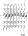
- the individual antenna units 14 may each comprise a plurality of patch antennas (see Fig. 3 ).
- the transmitting antenna device 13 is fed via a supply circuit 15, namely with the aid of a local oscillator 16. This generates a transmission signal S 0 .
- the transmission signal S 0 is a frequency module profiled electromagnetic wave whose frequency has a sawtooth shape in the embodiment.
- the transmission signal S 0 is frequency-modulated; its frequency is periodically between a first value - for example 23.8 GHz - and a second value - for example 24.2 GHz.
- the mean frequency of the transmission signal S 0 is 24 GHz in the exemplary embodiment.
- the local oscillator 16 is driven by the control device 5.
- the oscillator 16 is, for example, a voltage controlled oscillator (voltage controlled oscillator) which generates the transmission signal S 0. At a frequency which is dependent on the amplitude of a DC voltage provided to the oscillator 15 by the control means 5.
- the radar 3, 4 also includes one or - as in Fig. 2 schematically illustrated - a plurality of receivers 17.
- the receiving antenna device 18 may also be a two-dimensional antenna array.
- the receiving antenna device 18 is coupled to a feed circuit 19.
- the feed circuit 19 provides a signal S E , which is a receive signal.
- the received signal S E is amplified with the aid of a low-noise amplifier 20 (low noise amplifier), down-mixed by means of a mixer 21, low-pass filtered using a low-pass filter 22 and analog-digital-converted by means of an analog-to-digital converter 23.
- a low-noise amplifier 20 low noise amplifier
- the transmission signal S 0 is used; the transmission signal S 0 is fed to the mixer 21, namely for example by means of a directional coupler.
- the received digital signal S E is then processed by means of the control device 5. From the signal S E , the control device 5 determines, for example, the distance of an object, its relative speed, as well as a target angle.
- Fig. 2 is a schematic diagram of the radar 3, 4 and thus shows only schematically the operation of the radar 3, 4. So the radar device 3, 4 in Fig. 2 only shown as an example.
- the transmitting antenna device 13, and more precisely the feeding circuit 15, can be controlled such that it illuminates different subregions of the detection region 7 or 8 in succession by switching over.
- a transmitting lobe of the transmitting antenna device 13 can be pivoted electronically in the azimuthal direction, namely according to the phase array principle.
- the receiving antenna device 18 may have a broad reception characteristic in the azimuthal direction, with which the entire detection range 7 or 8 is covered.
- Other embodiments may alternatively realize narrow receive angle ranges in conjunction with broad transmit lobes.
- the transmitting antenna device 13 includes a plurality of antenna units 14, which in turn comprise a plurality of individual patch antennas. Namely, in the embodiment, the transmitting antenna device 13 includes eight antenna units 14 of the same structure. Each antenna unit 14 includes six patch antenna elements in the embodiment.
- All patch antenna elements are mounted on a common substrate. Attached to this substrate is also the feed circuit 15, which is constructed in the exemplary embodiment in microstrip technology.
- the feed circuit 15 comprises, for each antenna unit 14, apart from the two middle antenna units 14, an attenuator, via which the respective antenna unit 14 is coupled to the local oscillator 16. Namely, the outermost antenna units 14 are respectively coupled to an attenuator 24, the antenna units 14 adjacent to the outermost antenna units 14 each having one attenuator 25, and the antenna units 14 adjacent to the middle antenna units 14 each having one attenuator 26.
- the attenuators 24, 25, 26 have the same attenuation values in pairs:
- the attenuators 24 have a first attenuation value
- the attenuators 25 have a second attenuation value
- the attenuators 26 have a third attenuation value.
- the first attenuation value is greater than the second attenuation value
- the second attenuation value is greater than the third attenuation value.
- All attenuators 24, 25, 26 have the same phase characteristics, that is, the phase of an electromagnetic wave propagating through the attenuators 24, 25, 26 is shifted by the same amount.
- all attenuators 24, 25, 26 have the same effective line length and thus the same phase shift.
- the middle antenna units 14 are coupled with no attenuators, but in each case via a microstrip line 27 to the local oscillator 16.
- a microstrip line 27 is in Fig. 4a shown. How out Fig. 4a it emerges, the microstrip line 27 has a loop-shaped course with a meander loop 28.
- the effective line length of the microstrip line 27 can be adapted to the effective length of the attenuators 24, 25, 26, namely at the given, available space.
- the phase shift through the microstrip line 27 is thus adapted to the phase shifts by the attenuators 24, 25, 26.
- the microstrip line 27 is connected on the one hand to the associated antenna unit 14; on the other hand, it is coupled to the local oscillator 16, for example via a coaxial cable or other waveguide.
- the attenuators 24, 25, 26 are in the FIGS. 4b to 4d shown.
- the attenuators 24, 25, 26 are in Microstrip technology provided and thus include microstrip lines.
- a first port or first port 29 of the respective attenuators 24, 25, 26 is coupled to the local oscillator 16, for example via a coaxial cable or other waveguide.
- a second port 30 is connected to the respective antenna unit 14.
- the attenuators 24, 25, 26 each have a branching unit, namely a parallel branch 31 (T-junction), which has a first line branch 32 and a second line branch 33.
- the two line branches 32, 33 are brought together at a branching point 34, namely at the first gate 29.
- the first line branch 32 thus couples the associated antenna unit 14 to the local oscillator 16.
- the resistor 35 is an SMD component in the exemplary embodiment and is on the one hand to a separate from the parallel branch 31 microstrip contact surface 38 and on the other hand to an end portion of the second leg 33 at.
- the short-circuit element 37 connects the microstrip contact surface 38 with the ground.
- the resistor 35 with the short-circuit element 37 together form a reflection-free terminating element.
- the parallel branch 31 has two ⁇ / 4 transformers 39, 40, which have the function of matching the input impedance to the output impedance.
- Fig. 4b the attenuator 26 is shown, which serves for feeding the antenna units 14 which are adjacent to the middle antenna units 14.
- This attenuator 26 has a low attenuation value - the ⁇ / 4 transformer 39 is significantly wider than the ⁇ / 4 transformer 40th
- Fig. 4c the one attenuator 25 is shown which has the second, average attenuation value.
- the ⁇ / 4 transformer 39 is now slightly narrower than the according to Fig. 4b and also a little narrower than the ⁇ / 4 transformer 40 of the second leg 33.
- Attenuator 24 is used to power the outermost antenna units 14. It has the largest attenuation value; the ⁇ / 4 transformer 39 is correspondingly significantly narrower than the ⁇ / 4 transformer 40th
- the attenuators 24, 25, 26 can also be realized with directional couplers. Then, with the help of such a directional coupler, a part of the power of the transmission signal S 0 is tapped and can also be performed on a reflection-free termination element.
- an attenuator 24, 25, 26 is provided, which can be manufactured in a cost-effective, highly accurate manner with regard to the phase shift and the attenuation value, as well as reproducibly in large numbers.
- the phase of the electromagnetic wave is not affected.
- a desired attenuation value can be set precisely by a corresponding selection of the width of ⁇ / 4 transformers 39, 40 without much effort.
Landscapes
- Engineering & Computer Science (AREA)
- Radar, Positioning & Navigation (AREA)
- Remote Sensing (AREA)
- Physics & Mathematics (AREA)
- Computer Networks & Wireless Communication (AREA)
- General Physics & Mathematics (AREA)
- Electromagnetism (AREA)
- Computer Security & Cryptography (AREA)
- Radar Systems Or Details Thereof (AREA)
- Variable-Direction Aerials And Aerial Arrays (AREA)
- Waveguide Aerials (AREA)
- Details Of Aerials (AREA)
Description
Die Erfindung betrifft eine Fahrerassistenzeinrichtung für ein Fahrzeug, welche ein Radargerät zur Detektion von fahrzeugexternen Objekten umfasst. Das Radargerät weist eine Antenneneinheit zum Abstrahlen und/oder Empfangen elektromagnetischer Wellen sowie ein mit der Antenneneinheit gekoppeltes Dämpfungsglied zum Leiten und Dämpfen der elektromagnetischen Wellen auf. Über das Dämpfungsgebiet ist die Antenneneinheit mit einer Sender- und/oder Empfängereinrichtung des Radargeräts koppelbar. Die Erfindung betrifft außerdem ein Fahrzeug mit einer solchen Fahrerassistenzeinrichtung, wie auch ein Verfahren zum Betreiben eines Radargerätes in einem Fahrzeug.The invention relates to a driver assistance device for a vehicle, which comprises a radar device for detecting objects external to the vehicle. The radar device has an antenna unit for emitting and / or receiving electromagnetic waves and an attenuator coupled to the antenna unit for conducting and attenuating the electromagnetic waves. About the attenuation region, the antenna unit with a transmitter and / or receiver device of the radar device can be coupled. The invention also relates to a vehicle having such a driver assistance device, as well as to a method for operating a radar device in a vehicle.
Vorliegend gilt das Interesse dem Dämpfungsglied, welches zum Dämpfen der elektromagnetischen Wellen dient. Solche Dämpfungsglieder werden im Stand der Technik insbesondere bei Sendeantennengruppen eingesetzt, bei denen eine Schwenkung der Hauptkeule der Richtcharakteristik auf elektronischem Wege (Beamforming) oder eine Umschaltung zwischen verschiedenen Richtungen der Hauptkeule (Beam Switching) - ebenfalls auf elektronischem Wege - realisiert wird. Es werden im Stand der Technik eine Vielzahl von Antenneneinheiten eingesetzt; jede Antenneneinheit beinhaltet ein oder mehrere einzelne Antennenelemente und wird separat - das heißt unabhängig von den anderen Antenneneinheiten - gespeist. Die Antenneneinheiten, die beispielsweise nebeneinander angeordnet sein können, werden jeweils mit einem hochfrequenten Signal gespeist. Der Pegel der Signale nimmt ausgehend von einer mittleren Antenneneinheit beziehungsweise einem Zentrum der Antennengruppe zu den an den jeweiligen Rändern befindlichen Antenneneinheiten hin symmetrisch ab. Dies ist erforderlich, um die Nebenkeulen der Antennencharakteristik auf weniger als -13 dB gegenüber der Hauptkeule zu unterdrücken. Andernfalls ist bei Anregung aller Antenneneinheiten mit Signalen gleichen Pegels (so genannte "Boxcar Exitation") maximal eine Unterdrückung der Nebenkeulen von -13 dB erzielbar. Gerade zum Zwecke der Verringerung des Pegels für die einzelnen außerhalb der Mitte liegenden Antenneneinheiten werden Dämpfungsglieder eingesetzt (auch unter der Bezeichnung "Attenuator" oder "Abschwächer" bekannt). Diese müssen einen stabilen korrekten Dämpfungswert und vor allem keine Phasenverschiebung zueinander aufweisen.
Dämpfungsglieder können durch den Einsatz von Widerstandspaste - beispielsweise bei Herstellung der Antenneneinheiten in LTCC(Low Temperature Cofired Ceramics)-Technologie - realisiert werden. Es sind außerdem Widerstandsfolien bekannt, die bei Dämpfungsgliedern eingesetzt werden können. Die mit einer Widerstandspaste oder einer Widerstandsfolie aufgebauten Dämpfungsglieder weisen jedoch aufgrund von Prozesstoleranzen beziehungsweise Prozessungenauigkeiten erhebliche Streuungen der Widerstandswerte auf. Für Hochfrequenzsubstrate existiert bislang kein Verfahren, die Dämpfungswerte durch Aufbringen einer Widerstandspaste oder einer Widerstandsfolie mit höchster Genauigkeit beziehungsweise mit geringer Toleranz einzustellen.
Es sind aus dem Stand der Technik auch bereits hochgenaue Dämpfungsglieder bekannt, nämlich in SMD(Surface-Mounted-Device)-Technologie. Solche Bauelemente sind jedoch vergleichsweise teuer.
Eine weitere Möglichkeit besteht in dem Einsatz von π beziehungsweise T-Dämpfungsgliedern, die über drei Widerstände realisiert werden. Diese Dämpfungsglieder können jedoch im Frequenzbereich von Radargeräten - zum Beispiel 24 GHz - nicht mit ausreichender Genauigkeit hergestellt werden. Insbesondere die Reproduzierbarkeit der Phasenverschiebung eines jeden Dämpfungsgliedes kann bei dieser Alternative - aufgrund der Notwendigkeit des Einsatzes von SMD-Widerständen - nicht erzielt werden.
Diese Aufgabe wird erfindungsgemäß durch eine Fahrerassistenzeinrichtung mit den Merkmalen gemäß Patentanspruch 1, wie auch durch ein Fahrzeug mit den Merkmalen gemäß Patentanspruch 7 sowie ein Verfahren mit den Merkmalen gemäß Patentanspruch 8 gelöst. vorteilhafte Ausführungen der Erfindung sind Gegenstand der abhängigen Patentansprüche und der Beschreibung.In the present case, the interest is the attenuator, which serves to attenuate the electromagnetic waves. Such attenuators are used in the prior art in particular transmission antenna groups in which a pivoting of the main lobe of the directional characteristic by electronic means (beam forming) or switching between different directions of the main lobe (beam switching) - also electronically - is realized. There are used in the prior art, a plurality of antenna units; Each antenna unit includes one or more individual antenna elements and is powered separately - that is independently of the other antenna units. The antenna units, which may be arranged side by side, for example, are each fed with a high-frequency signal. The level of the signals decreases symmetrically starting from a central antenna unit or a center of the antenna group towards the antenna units located at the respective edges. This is necessary to suppress the side lobes of the antenna characteristic to less than -13 dB with respect to the main lobe. Otherwise, if all antenna units with signals of the same level (so-called "Boxcar Exitation") are excited, a maximum of -13 dB suppression of the sidelobes can be achieved. Especially for the purpose of reducing the level of the individual out-of-center antenna units attenuators are used (even under the Designation "attenuator" or "attenuator" known). These must have a stable correct attenuation value and above all no phase shift from one another.
Attenuators can be realized through the use of resistor paste - for example when manufacturing the antenna units in LTCC (Low Temperature Cofired Ceramics) technology. There are also known resistance foils that can be used with attenuators. However, due to process tolerances or process inaccuracies, the attenuators constructed with a resistance paste or a resistance foil have considerable variations in the resistance values. For high-frequency substrates, no method yet exists for adjusting the attenuation values by applying a resistance paste or a resistance foil with the highest accuracy or with a low tolerance.
There are already known from the prior art also highly accurate attenuators, namely in SMD (Surface Mounted Device) technology. However, such components are relatively expensive.
Another possibility is the use of π or T-attenuators, which are realized via three resistors. However, these attenuators can not be made with sufficient accuracy in the frequency range of radars - for example, 24 GHz. In particular, the reproducibility of the phase shift of each attenuator can not be achieved in this alternative - due to the need for the use of SMD resistors.
This object is achieved by a driver assistance device with the features according to claim 1, as well as by a vehicle having the features according to claim 7 and a method with the features according to
Eine erfindungsgemäße Fahrerassistenzeinrichtung für ein Fahrzeug umfasst ein Radargerät zur Detektion von fahrzeugexternen Objekten. Das Radargerät umfasst eine Antenneneinheit zum Abstrahlen und/oder Empfangen elektromagnetischer Wellen sowie ein mit der Antenneneinheit gekoppeltes Dämpfungsglied zum Leiten und Dämpfen der elektromagnetischen Wellen. Über das Dämpfungsglied ist die Antenneneinheit mit einer Sender- und/oder Empfängereinrichtung des Radargeräts koppelbar. Das Dämpfungsglied umfasst eine Verzweigungseinheit mit einem ersten Leitungszweig zum Leiten der gedämpften elektromagnetischen Wellen zwischen der Sender- und/oder Empfängereinrichtung einerseits und der Antenneneinheit andererseits sowie einen mit dem ersten Leitungszweig gekoppelten zweiten Leitungszweig, welcher mit einem reflexionsfreien Abschlusselement abgeschlossen ist.A driver assistance device according to the invention for a vehicle comprises a radar device for detecting objects external of the vehicle. The radar device comprises an antenna unit for emitting and / or receiving electromagnetic waves and an attenuator coupled to the antenna unit for conducting and attenuating the electromagnetic waves. About the attenuator, the antenna unit with a transmitter and / or receiver device of the radar device can be coupled. The attenuator comprises a branching unit having a first line branch for conducting the attenuated electromagnetic waves between the transmitter and / or receiver device on the one hand and the antenna unit on the other hand and a second line branch coupled to the first line branch and terminated with a reflection-free terminating element.
Der erfindungsgemäße Effekt wird also durch ein Dämpfungsglied mit einer Verzweigungseinheit erzielt, durch welche ein Teil der Leistung der elektromagnetischen Wellen abgegriffen und abgeführt wird, nämlich auf ein reflexionsfreies Abschlusselement. Also übernimmt die Verzeigungseinheit die Funktion des Teilens der Leistung der elektromagnetischen Wellen. Der erste Leitungszweig wird zur Speisung der Antenneneinheit verwendet, während der zweite Leitungszweig mit dem reflexionsfreien Abschlusselement abgeschlossen und somit zum Vernichten des abgegriffenen Teils der Leistung dient.The effect of the invention is thus achieved by an attenuator with a branching unit, through which a part of the power of the electromagnetic waves is tapped and removed, namely on a reflection-free terminating element. Thus, the unit of the recognition takes over the function of dividing the power of the electromagnetic waves. The first line branch is used for feeding the antenna unit, while the second line branch terminates with the reflection-free terminating element and thus serves to destroy the tapped part of the power.
Die erfindungsgemäße Vorgehensweise hat diverse Vorteile: Das Dämpfungsglied kann kostengünstig hergestellt werden; es sind lediglich zwei Leitungszweige - zum Beispiel zwei Streifenleitungen - und ein reflexionsfreies Abschlusselement erforderlich. Es müssen außerdem keine diskreten Bauelemente, wie SMD-Bauelemente, keine Widerstandspaste sowie keine Widerstandsfolie in den ersten Leitungszweig - also den Signalzweig der Antenneneinheit - eingesetzt werden. Dies vermeidet Ungenauigkeiten in der Phasenverschiebung des Dämpfungsgliedes, wie auch in seinem Dämpfungswert, was im Stand der Technik zur Verschlechterung der Richtcharakteristik und somit der gesamten Leistungsfähigkeit des Radargerätes führt. Es ist somit in einer Serienfertigung das Risiko von Abweichungen der Phasenverschiebung und des Dämpfungswerts einzelner Dämpfungsglieder von Sollwerten auf ein Minimum reduziert. Die Verzweigungseinheit kann nämlich mittels recht genau herstellbarer Leitungsstrukturen - beispielsweise Leiterbahnstrukturen auf einer Platine - realisiert werden, was gleich bleibende Eigenschaften in der Serienfertigung mit großen Stückzahlen gewährleistet. Die für die Herstellung der Verzweigungseinheit notwendigen Kosten sind sehr gering, da keine speziellen und teuren Hochfrequenzbauelemente, Materialien oder Prozesse benötigt werden.The procedure according to the invention has various advantages: the attenuator can be produced inexpensively; only two line branches - for example two strip lines - and one reflection-free terminating element are required. In addition, no discrete components, such as SMD components, no resistance paste and no resistance film in the first leg - so the signal branch of the antenna unit - are used. This avoids inaccuracies in the phase shift of the attenuator, as well as in its attenuation value, which leads in the prior art to the deterioration of the directional characteristic and thus the overall performance of the radar. It is thus reduced in a series production, the risk of deviations of the phase shift and the attenuation of individual attenuators of setpoints to a minimum. Namely, the branching unit can be realized by means of line structures that can be produced with precision, for example printed circuit board structures on a printed circuit board, which ensures consistently high-volume series production characteristics. The necessary for the production of the branching unit Costs are very low, as no special and expensive high-frequency components, materials or processes are needed.
Die Verzweigungseinheit ist bevorzugt in Streifenleitertechnik, insbesondere in Mikrostreifentechnik, realisiert. Dann sind der erste und der zweite Leitungszweig jeweils eine Streifenleitung, insbesondere eine Mikrostreifenleitung. Es können aber auch andere Arten von Streifenleitungen vorgesehen sein, wie beispielsweise Koplanarleitungen und ähnliche. Die Ausführung der Verzweigungseinheit in Streifenleitertechnik sorgt - insbesondere bei Einsatz von Patch-Antennen - für ein kompaktes und bauraumsparendes Dämpfungsglied. Streifenleitungen sind außerdem kostengünstiger als andere Wellenleitungen und lassen sich mit hoher Genauigkeit reproduzierbar und materialsparend fertigen. Dies erweist sich insbesondere bei einer Vielzahl von Antenneneinheiten als besonders vorteilhaft, die - außer den mittleren Antenneneinheiten - jeweils ein Dämpfungsglied benötigen. Dann sind nämlich eine Vielzahl von Verzweigungseinheiten mit gleichen Phaseneigenschaften und höchst genauen Dämpfungswerten nötig.The branching unit is preferably realized in stripline technology, in particular in microstrip technology. Then, the first and the second line branch are each a stripline, in particular a microstrip line. However, other types of strip lines may also be provided, such as coplanar lines and the like. The design of the branching unit in stripline technology ensures - especially when using patch antennas - for a compact and space-saving attenuator. Strip lines are also cheaper than other waveguides and can be produced with high accuracy reproducible and material-saving. This proves to be especially advantageous in the case of a large number of antenna units which, in addition to the middle antenna units, each require one attenuator. In that case, a large number of branching units with the same phase characteristics and highly accurate attenuation values are necessary.
Es erweist sich als besonders vorteilhaft, wenn die Verzweigungseinheit eine Parallelzweigung (auch unter der Bezeichnung "T-junction" oder "Leistungsteiler" bekannt) aufweist. Dann sind der erste und der zweite Leitungszweig elektrisch miteinander verbunden. Diese Ausführungsform sorgt für ein besonders kompaktes Dämpfungsglied. Somit kann das Dämpfungsglied auch bei solchen Radargeräten eingesetzt werden, bei denen relativ wenig Platz zwischen den einzelnen, auf einem gemeinsamen Substrat angebrachten Antenneneinheiten zur Verfügung steht. Eine Parallelzweigung hat außerdem den Vorteil, dass der gewünschte Dämpfungswert des Dämpfungsgliedes ohne viel Aufwand und besonders exakt realisiert werden kann; durch geeignete Wahl der Leitungsimpedanzen des ersten und des zweiten Leitungszweigs - und genauer gesagt der jeweiligen λ/4-Transformatoren - lassen sich die gewünschten Leistungsverteilungen realisieren. Auch die Impedanzanpassung kann bei einer Parallelzweigung ohne viel Aufwand - durch Einsatz von λ/4-Transformatoren - erzielt werden. Es ist vorteilhaft, wenn zumindest ein Abschnitt der jeweiligen λ/4-Transformatoren ringsegmentförmig bzw. schlingenförmig ausgeführt ist; dann ist die Verzweigungseinheit besonders kompakt.It proves to be particularly advantageous if the branching unit has a parallel branch (also known as "T-junction" or "power divider"). Then, the first and the second leg are electrically connected together. This embodiment provides for a particularly compact attenuator. Thus, the attenuator can also be used in radar devices in which relatively little space between the individual, mounted on a common substrate antenna units is available. A parallel branch also has the advantage that the desired damping value of the attenuator can be realized without much effort and particularly accurate; by suitable choice of the line impedances of the first and the second line branch - and more precisely of the respective λ / 4 transformers - can realize the desired power distributions. The impedance matching can be achieved in a parallel branch without much effort - by using λ / 4 transformers. It is advantageous if at least a portion of the respective λ / 4 transformers is designed ring-segment-shaped or loop-shaped; then the branching unit is particularly compact.
In einer alternativen Ausführungsform weist die Verzweigungseinheit einen Richtkoppler auf, nämlich insbesondere einen TEM(Transverse Electro Magnetic)-Leitungskoppler oder einen Hybrid-Koppler (auch unter den Bezeichnungen "4 x λ/4-Leitungskoppler" oder "Branchline-Koppler" oder "90°-Ringhybrid" bekannt). Bei einem TEM-Leitungskoppler ist der erste Leitungszweig von dem zweiten Leitungszweig elektrisch getrennt und parallel zum zweiten Leitungszweig angeordnet. Auch mit solchen Richtkopplern kann ein Teil der Leistung der elektromagnetischen Wellen abgegriffen und auf das reflexionsfreie Abschlusselement abgeführt werden.In an alternative embodiment, the branching unit comprises a directional coupler, namely in particular a TEM (Transverse Electro Magnetic) line coupler or a hybrid coupler (also referred to as "4 × λ / 4 line couplers"). or "branchline coupler" or "90 ° ring hybrid"). In a TEM line coupler, the first line branch is electrically separated from the second line branch and arranged parallel to the second line branch. Even with such directional couplers, a part of the power of the electromagnetic waves can be tapped and removed to the reflection-free terminating element.
Das reflexionsfreie Abschlusselement befindet sich in dem zweiten Leitungszweig und beeinflusst somit nicht die Phase des über den ersten Leitungszweig übertragenen Signals. Somit kann das Abschlusselement prinzipiell auf beliebige Art und Weise realisiert werden; es ist lediglich erforderlich, dass keine nennenswerten Reflexionen am Abschlusselement stattfinden. Unter dem "reflexionsfreien Abschlusselement" wird insbesondere ein solches verstanden, bei welchem die Leistungsreflexionen weniger als -10 dB, insbesondere weniger als -15 dB, noch bevorzugter weniger als -20 dB, betragen. Hinsichtlich des reflexionsfreien Abschlusselements sind verschiedenste Ausführungsformen sinnvoll möglich:The reflection-free terminating element is located in the second line branch and thus does not influence the phase of the signal transmitted via the first line branch. Thus, the final element can in principle be realized in any manner; it is only necessary that no significant reflections take place on the terminating element. The term "reflection-free terminating element" is understood in particular to mean one in which the power reflections are less than -10 dB, in particular less than -15 dB, even more preferably less than -20 dB. With regard to the reflection-free terminating element, a wide variety of embodiments are meaningfully possible:
Das Abschlusselement kann einen Widerstand aufweisen, der über ein elektrisches Kurzschlusselement auf ein Bezugspotential - das heißt auf Masse - geführt ist. Ist der zweite Leitungszweig eine Mikrostreifenleitung, so handelt es sich bei dem Kurzschlusselement um ein sich über ein Substrat hindurch erstreckendes Element, welches den Widerstand mit einer Massenfläche elektrisch verbindet (via). Auf diesem Wege gelingt es, ohne viel Aufwand ein reflexionsfreies Abschlusselement bereitzustellen; der Widerstand kann ein SMD-Bauelement, eine Widerstandspaste und/oder eine Widerstandsfolie sein.The termination element may have a resistance, which is guided via an electrical short-circuit element to a reference potential - that is, to ground. If the second leg is a microstrip line, the shorting element is an element extending across a substrate which electrically connects (via) the resistor to a ground plane. In this way, it is possible to provide a reflection-free closing element without much effort; the resistor may be an SMD device, a resistor paste and / or a resistor foil.
Das Abschlusselement kann aber auch ein von einem Bezugspotential elektrisch getrennter beziehungsweise ein masseloser Absorber sein. Dann erübrigt sich der Einsatz eines Kurzschlusselementes. Ein solcher Absorber kann beispielsweise in Form eines Absorberkeils, eines Spiralabsorbers, eines Resonanzabsorbers oder eines Widerstandsbelages bereitgestellt sein. Alle genannten Absorberarten weisen einen kleinen Reflexionsfaktor auf.However, the terminating element can also be one of a reference potential electrically separate or a massless absorber. Then the use of a short-circuit element is unnecessary. Such an absorber can be provided, for example, in the form of an absorber wedge, a spiral absorber, a resonance absorber or a resistance lining. All abovementioned absorber types have a small reflection factor.
Das Radargerät kann zumindest vier Antenneneinheiten - zum Beispiel acht Antenneneinheiten - aufweisen. Zumindest zwei Antenneneinheiten können jeweils über ein genanntes Dämpfungsglied mit der Sender- und/oder Empfängereinrichtung des Radargerätes gekoppelt sein. Die jeweiligen Dämpfungsglieder können unterschiedliche Dämpfungswerte aufweisen. In einer Verwirklichung dieser Ausführungsform kann das Radargerät eine Antennengruppe mit acht Antenneneinheiten beinhalten, die jeweils eine Vielzahl von Patch-Antennenelementen aufweisen. Jede Antenneneinheit kann mit der Sender- und/oder Empfängereinrichtung separat gekoppelt sein. Die zwei äußersten Antenneneinheiten können jeweils über ein solches Dämpfungsglied mit der Sender-und/oder Empfängereinrichtung gekoppelt sein, welches den größten Dämpfungswert aufweist. Die zwei mittleren Antenneneinheiten sind bevorzugt über keine Dämpfungsglieder mit der Sender- und/oder Empfängereinrichtung gekoppelt; es wird bevorzugt lediglich die Länge der die mittleren Antenneneinheiten mit der Sender-und/oder Empfängereinrichtung koppelnden Wellenleitungen und somit ihre Phasenverschiebung an die Phasenverschiebung der Dämpfungsglieder angepasst. Die zu den mittleren Antenneneinheiten nach außen hin benachbarten Antenneneinheiten sind bevorzugt jeweils über ein solches Dämpfungsglied mit der Sender- und/oder Empfängereinrichtung gekoppelt, welches den geringsten Dämpfungswert aufweist. Die zu den äußersten Antenneneinheiten nach innen hin benachbarten Antenneneinheiten sind jeweils mit einem solchen Dämpfungsglied gekoppelt, welches einen mittleren Dämpfungswert aufweist. Es liegt somit eine bezüglich der mittleren Antenneneinheiten symmetrische Pegelverteilung der Signale vor.The radar device can have at least four antenna units-for example, eight antenna units. At least two antenna units can each be coupled via a named attenuator to the transmitter and / or receiver device of the radar device. The respective attenuators may have different attenuation values. In one implementation of this embodiment, the Radar device include an antenna array with eight antenna units, each having a plurality of patch antenna elements. Each antenna unit may be separately coupled to the transmitter and / or receiver device. The two outermost antenna units can each be coupled via such an attenuator to the transmitter and / or receiver device, which has the largest attenuation value. The two middle antenna units are preferably coupled via no attenuators to the transmitter and / or receiver device; It is preferred that only the length of the waveguides coupling the central antenna units to the transmitter and / or receiver device and thus their phase shift be adapted to the phase shift of the attenuators. The antenna units adjacent to the middle antenna units are preferably each coupled via such an attenuation element to the transmitter and / or receiver device which has the lowest attenuation value. The antenna units which are inwardly adjacent to the outermost antenna units are each coupled to such an attenuator which has an average attenuation value. There is thus a symmetrical level distribution of the signals relative to the average antenna units.
Es wird bevorzugt ein Dauerstrichradar als Radargerät verwendet, welcher zum Abstrahlen einer frequenzmodulierten kontinuierlichen elektromagnetischen Welle ausgebildet ist (auch unter der Bezeichnung FMCW(frequency modulated continuous wave)-Radar bekannt). Mit einem solchen Radargerät gelingt es, die Entfernung eines Objektes von selbigem Radargerät zu bestimmen, wie auch die relative Geschwindigkeit des Objekts bezüglich des Radargeräts sowie die relative Position. Das Radargerät kann eine Sendeantenneneinrichtung sowie eine davon separate Empfangsantenneneinrichtung beinhalten. Das genannte Dämpfungsglied wird bevorzugt für die Sendeantenneneinrichtung verwendet. Dann ist die Antenneneinheit über das Dämpfungsglied mit einer Sendereinrichtung gekoppelt, während die Empfangsantenneneinrichtung mit einer Empfängereinrichtung gekoppelt ist. Eine solche Empfängereinrichtung kann zum Beispiel einen Mischer, einen Tiefpassfilter, einen rauscharmen Verstärker sowie einen Analog-Digital-Wandler umfassen. Die durch die Empfangsantenneneinrichtung empfangenen Signale werden dann in der Empfängereinrichtung in das Basisband herabgemischt, tiefpassgefiltert und analog-digital-gewandelt beziehungsweise diskretisiert. Die Sendeantenneneinrichtung kann mittels eines lokalen Oszillators zur Erzeugung eines Sendesignals gespeist werden. Das Sendesignal kann auch dem Mischer in der Empfängereinrichtung zugeführt werden, um die empfangenen Signale in das Basisband herabzumischen. Die Sendeantenneneinrichtung kann im Fahrzeug zumindest in azimutaler Richtung phasengesteuert werden, um so insgesamt einen relativ breiten Azimutwinkelbereich mit einer schmalen Hauptkeule der Richtcharakteristik in horizontaler Richtung erfassen zu können.A continuous wave radar is preferably used as the radar device, which is designed to emit a frequency-modulated continuous electromagnetic wave (also known as FMCW (frequency modulated continuous wave) radar). With such a radar device, it is possible to determine the distance of an object from the same radar device, as well as the relative speed of the object with respect to the radar device and the relative position. The radar device may include a transmitting antenna device and a separate receiving antenna device. Said attenuator is preferably used for the transmitting antenna device. Then, the antenna unit is coupled via the attenuator to a transmitter device, while the receiver antenna device is coupled to a receiver device. Such a receiver device may comprise, for example, a mixer, a low-pass filter, a low-noise amplifier and an analog-to-digital converter. The signals received by the receiving antenna device are then mixed down in the receiver device into the baseband, low-pass filtered and analog-to-digital converted or discretized. The transmit antenna device may be powered by a local oscillator to generate a transmit signal. The transmit signal may also be supplied to the mixer in the receiver device to down-mix the received signals into the baseband. The Transmitting antenna device can be phased in the vehicle at least in the azimuthal direction, so as to be able to detect a total of a relatively wide Azimutwinkelbereich with a narrow main lobe of the directional characteristic in the horizontal direction.
Ein erfindungsgemäßes Fahrzeug, insbesondere ein Kraftwagen, umfasst eine erfindungsgemäße Fahrerassistenzeinrichtung oder eine bevorzugte Ausgestaltung davon.A vehicle according to the invention, in particular a motor vehicle, comprises a driver assistance device according to the invention or a preferred embodiment thereof.
Ein erfindungsgemäßes Verfahren ist zum Betreiben eines Radargerätes einer Fahrerassistenzeinrichtung in einem Fahrzeug ausgelegt. Es werden elektromagnetische Wellen durch eine Antenneneinheit des Radargerätes abgestrahlt und/oder empfangen und über ein mit der Antenneneinheit gekoppeltes Dämpfungsglied geleitet und gedämpft, über welches die Antenneneinheit mit einer Sender- und/oder Empfängereinrichtung des Radargeräts gekoppelt ist. Die elektromagnetischen Wellen werden über einen ersten Leitungszweig einer Verzweigungseinheit des Dämpfungsgliedes zwischen der Sender- und/oder Empfängereinrichtung einerseits und der Antenneneinheit andererseits geleitet sowie über einen mit dem ersten Leitungszweig gekoppelten zweiten Leitungszweig auf ein reflexionsfreies Abschlusselement geführt.A method according to the invention is designed for operating a radar device of a driver assistance device in a vehicle. Electromagnetic waves are radiated and / or received by an antenna unit of the radar device and passed and attenuated via an attenuator coupled to the antenna unit via which the antenna unit is coupled to a transmitter and / or receiver device of the radar device. The electromagnetic waves are conducted via a first branch of a branching unit of the attenuator between the transmitter and / or receiver device on the one hand and the antenna unit on the other hand and guided via a coupled with the first leg branch second leg on a reflection-free termination element.
Die mit Bezug auf die erfindungsgemäße Fahrerassistenzeinrichtung vorgestellten bevorzugten Ausführungsformen und deren Vorteile gelten entsprechend für das erfindungsgemäße Fahrzeug und das erfindungsgemäße Verfahren.The preferred embodiments presented with reference to the driver assistance device according to the invention and their advantages apply correspondingly to the vehicle according to the invention and to the method according to the invention.
Weitere Vorteile der Erfindung ergeben sich aus den Ansprüchen, den Figuren und der Figurenbeschreibung. Alle vorstehend in der Beschreibung genannten Merkmale und Merkmalskombinationen sowie die nachfolgend in der Figurenbeschreibung genannten und/oder in den Figuren alleine gezeigten Merkmale und Merkmalskombinationen sind nicht nur in der jeweils angegebenen Kombination, sondern auch in anderen Kombinationen oder auch in Alleinstellung verwendbar.Further advantages of the invention will become apparent from the claims, the figures and the description of the figures. All features and feature combinations mentioned above in the description as well as the features and feature combinations mentioned below in the description of the figures and / or shown alone in the figures can be used not only in the respectively indicated combination but also in other combinations or also alone.
Die Erfindung wird nun anhand einzelner bevorzugter Ausführungsbeispiele näher erläutert, wie auch unter Bezugnahme auf die beigefügten Zeichnungen.The invention will now be explained in more detail with reference to individual preferred embodiments, as well as with reference to the accompanying drawings.
Es zeigen:
- Fig. 1
- in schematischer Darstellung eine Draufsicht auf ein Kraftfahrzeug gemäß einer Ausführungsform der Erfindung;
- Fig. 2
- ein Blockschaltbild eines Radargeräts, wie es in dem Kraftfahrzeug gemäß
Fig. 1 eingesetzt wird; - Fig. 3
- in schematischer Darstellung eine Sendeantenneneinrichtung, wie sie in dem Radargerät gemäß
Fig. 2 eingesetzt wird; - Fig. 4a
- in schematischer und mehrfach vergrößerter Darstellung eine Wellenleitung (Layout) mit angepasster Länge beziehungsweise Phasenverschiebung; und
- Fig. 4b bis 4d
- in schematischer und mehrfach vergrößerter Darstellung jeweils ein Dämpfungsglied (Layout) mit einem unterschiedlichen Dämpfungswert gemäß einer Ausführungsform der Erfindung.
- Fig. 1
- a schematic plan view of a motor vehicle according to an embodiment of the invention;
- Fig. 2
- a block diagram of a radar device, as in the motor vehicle according to
Fig. 1 is used; - Fig. 3
- a schematic representation of a transmitting antenna device, as in the radar device according to
Fig. 2 is used; - Fig. 4a
- in schematic and multiply enlarged view of a waveguide (layout) with adapted length or phase shift; and
- Fig. 4b to 4d
- in schematic and multiply enlarged representation in each case an attenuator (layout) with a different attenuation value according to an embodiment of the invention.
In den Figuren werden gleiche und funktionsgleiche Elemente mit den gleichen Bezugszeichen versehen.In the figures, identical and functionally identical elements are provided with the same reference numerals.
Ein in
Das erste Radargerät 3 erfasst einen Erfassungsbereich 7. Der Erfassungsbereich 7 ist durch einen Azimutwinkel α definiert, welcher in
Entsprechend weist das zweite Radargerät 4 einen Erfassungsbereich 8 auf, welcher durch einen entsprechenden Azimutwinkel α definiert ist. Der Azimutwinkel α ist durch zwei Linien 8a, 8b begrenzt.Accordingly, the
Die Azimutwinkel α betragen im Ausführungsbeispiel etwa 170°. Die Erfassungsbereiche 7, 8 der Radargeräte 3, 4 überschneiden sich, so dass ein Überlappungsbereich 9 gegeben ist. Der Überlappungsbereich 9 ist durch die Linien 7b, 8b winkelig begrenzt. Im Ausführungsbeispiel beträgt ein Öffnungswinkel β des Überlappungsbereichs 9 etwa 70°.The azimuth angle α amount to about 170 ° in the embodiment. The
In ihren jeweiligen Erfassungsbereichen 7, 8 können die Radargeräte 3, 4 Objekte orten. Insbesondere können die Radargeräte 3, 4 eine Entfernung eines Objektes von dem jeweiligen Radargerät 3, 4, einen Zielwinkel sowie eine relative Geschwindigkeit des Objektes bezüglich des Kraftfahrzeugs 1 bestimmen. Wie aus
Der lokale Oszillator 16 wird durch die Steuereinrichtung 5 angesteuert. Der Oszillator 16 ist zum Beispiel ein spannungsgesteuerter Oszillator (voltage controlled oszillator), welcher das Sendesignal S0.mit einer solchen Frequenz erzeugt, die abhängig von der Amplitude einer von der Steuereinrichtung 5 an dem Oszillator 15 bereitgestellten Gleichspannung ist.The
Das Radargerät 3, 4 umfasst außerdem einen oder - wie in
Die Sendeantenneneinrichtung 13, und genauer gesagt die Speiseschaltung 15, kann so gesteuert werden, dass sie zeitlich nacheinander durch Umschalten verschiedene Teilbereiche des Erfassungsbereichs 7 beziehungsweise 8 beleuchtet. Zum Beispiel kann dazu eine Sendekeule der Sendeantenneneinrichtung 13 elektronisch in azimutaler Richtung geschwenkt werden, nämlich nach dem Phase-Array-Prinzip. Die Empfangsantenneneinrichtung 18 kann in diesem Fall in azimutaler Richtung eine breite Empfangscharakteristik aufweisen, mit der der gesamte Erfassungsbereich 7 beziehungsweise 8 abgedeckt wird. Andere Ausgestaltungen können alternativ schmale Empfangswinkelbereiche in Verbindung mit breiten Sendekeulen realisieren.The transmitting
Vorliegend richtet sich das Interesse auf die Speiseschaltung 15 der Sendeantenneneinrichtung 13, nämlich auf ihre Dämpfungsglieder. Bezug nehmend auf
Alle Patch-Antennenelemente sind an einem gemeinsamen Substrat angebracht. An diesem Substrat angebracht ist außerdem die Speiseschaltung 15, die im Ausführungsbeispiel in Mikrostreifentechnologie aufgebaut ist.All patch antenna elements are mounted on a common substrate. Attached to this substrate is also the
Die Speiseschaltung 15 umfasst für jede Antenneneinheit 14 außer den beiden mittleren Antenneneinheiten 14 jeweils ein Dämpfungsglied, über welches die jeweilige Antenneneinheit 14 mit dem lokalen Oszillator 16 gekoppelt ist. Und zwar sind die äußersten Antenneneinheiten 14 jeweils mit einem Dämpfungsglied 24 gekoppelt, die zu den äußersten Antenneneinheiten 14 benachbarten Antenneneinheiten mit jeweils einem Dämpfungsglied 25, und die zu den mittleren Antenneneinheiten 14 benachbarten Antenneneinheiten 14 mit jeweils einem Dämpfungsglied 26. Die Dämpfungsglieder 24, 25, 26 weisen paarweise jeweils gleiche Dämpfungswerte auf:The
Die Dämpfungsglieder 24 haben einen ersten Dämpfungswert, die Dämpfungsglieder 25 einen zweiten Dämpfungswert, und die Dämpfungsglieder 26 einen dritten Dämpfungswert. Der erste Dämpfungswert ist größer als der zweite Dämpfungswert, und der zweite Dämpfungswert ist größer als der dritte Dämpfungswert. Alle Dämpfungsglieder 24, 25, 26 haben gleiche Phaseneigenschaften, das heißt die Phase einer sich über die Dämpfungsglieder 24, 25, 26 ausbreitenden elektromagnetischen Welle wird um denselben Betrag verschoben. Also weisen alle Dämpfungsglieder 24, 25, 26 dieselbe effektive Leitungslänge und somit dieselbe Phasenverschiebung auf.The
Die mittleren Antenneneinheiten 14 sind mit keinen Dämpfungsgliedern, sondern jeweils über eine Mikrostreifenleitung 27 mit dem lokalen Oszillator 16 gekoppelt. Eine solche Mikrostreifenleitung 27 ist in
Die Dämpfungsglieder 24, 25, 26 gemäß einer Ausführungsform der Erfindung sind in den
Der Widerstand 35 mit dem Kurzschlusselement 37 bilden insgesamt ein reflexionsfreies Abschlusselement.The
Die Parallelzweigung 31 weist zwei λ/4-Transformatoren 39, 40 auf, die die Funktion der Anpassung der Eingangsimpedanz an die Ausgangsimpedanz aufweisen. Durch geeignete Wahl der Impedanzen der beiden λ/4-Transformatoren lassen sich die gewünschten Leistungsverteilungen der Parallelzweigung 31 und somit die erforderlichen Dämpfungswerte realisieren.The
In
In
Das in
Prinzipiell können die Dämpfungsglieder 24, 25, 26 auch mit Richtkopplern realisiert werden. Dann wird mit Hilfe eines solchen Richtkopplers ein Teil der Leistung des Sendesignals S0 abgegriffen und kann ebenfalls auf ein reflexionsfreies Abschlusselement geführt werden.In principle, the
Insgesamt wird also ein Dämpfungsglied 24, 25, 26 bereitgestellt, welches kostengünstig, höchst genau bezüglich der Phasenverschiebung und des Dämpfungswertes, wie auch in großen Stückzahlen reproduzierbar hergestellt werden kann. Es sind keine zusätzlichen Bauelemente - wie zum Beispiel SMD-Bauelemente - in denjenigen Leitungszweig 32 eingesetzt, über welchen die Antenneneinheit 14 gespeist wird. Somit wird auch die Phase der elektromagnetischen Welle nicht beeinträchtigt. Ein gewünschter Dämpfungswert lässt sich durch eine entsprechende Auswahl der Breite von λ/4-Transformatoren 39, 40 ohne viel Aufwand genau einstellen.Overall, therefore, an
Claims (8)
- Driver assistance device (2) for a vehicle (1), having a radar apparatus (3, 4) for detecting objects which are external to the vehicle, which radar apparatus (3, 4) has an antenna unit (14) for irradiating and/or receiving electromagnetic waves (S0, SE) and a damping element (24, 25, 26) which is coupled to the antenna unit (14) and has the purpose of directing and damping the electromagnetic waves (S0, SE), by means of which damping element (24, 25, 26) the antenna unit (14) can be coupled to a transmitter and/or receiver device (16, 17) of the radar apparatus (3, 4),
characterized in that
the damping element (24, 25, 26) has a branching unit (31) with a first line branch (32) for directing the damped electromagnetic waves (S0, SE) between the transmitter and/or receiver device (16, 17), on the one hand, and the antenna unit (14) on the other, as well as a second line branch (33) which is coupled to the first line branch (32) and is terminated with a reflection-free terminating element (35, 37), wherein the radar apparatus (3, 4) has at least two antenna units (14) which can each be coupled via a specified damping element (24, 25, 26) to the transmitter and/or receiver device (16, 17) of the radar apparatus (3, 4), the damping elements (24, 25, 26) have different damping values and all the damping elements (24, 25, 26) have the same effective line length and thus the same phase shift. - Driver assistance device (2) according to Claim 1,
characterized in that
the branching unit (31) is implemented in strip conductor technology, in particular in microstrip technology, with the result that the first and the second line branches (32, 33) are each a strip line, in particular a microstrip line. - Driver assistance device (2) according to Claim 1 or 2,
characterized in that
the branching unit (31) has a parallel branch (31), with the result that the first and the second line branches (32, 33) are electrically connected to one another. - Driver assistance device (2) according to Claim 1 or 2,
characterized in that
the branching unit (31) has a directional coupler, in particular a TEM line coupler, wherein the first line branch (32) is preferably electrically isolated from the second line branch (33) and is arranged parallel to the second line branch (33). - Driver assistance device (2) according to one of the preceding claims,
characterized in that
the terminating element (35, 37) has a resistor (35) which is connected to a reference potential via an electrical short-circuiting element (37). - Driver assistance device (2) according to one of Claims 1 to 4,
characterized in that
the terminating element (35, 37) is an absorber which is electrically isolated from a reference potential. - Vehicle (1), in particular a motor vehicle, having a driver assistance device (2) according to one of the preceding claims.
- Method for operating a radar apparatus of a driver assistance device (2) in a vehicle (1), wherein electromagnetic waves (S0, SE) are irradiated and/or received by an antenna unit (14) of the radar apparatus (3, 4), and are directed and damped by means of a damping element (24, 25, 26) which is coupled to the antenna unit (14) and by means of which the antenna unit (14) is coupled to a transmitter and/or receiver device (16, 17) of the radar apparatus (3, 4),
characterized in that
the electromagnetic waves (S0, SE) are directed via a first line branch (32) of a branching unit (31) of the damping element (24, 25, 26) between the transmitter and/or receiver device (16, 17), on the one hand and the antenna unit (14), on the other, and are conducted to a reflection-free terminating element (35, 37) via a second line branch (33) which is coupled to the first line branch (32), wherein the radar apparatus (3, 4) has at least two antenna units (14) which can each be coupled via a specified damping element (24, 25, 26) to the transmitter and/or receiver device (16, 17) of the radar apparatus (3, 4), the damping elements (24, 25, 26) have different damping values and all the damping elements (24, 25, 26) have the same effective line length and thus the same phase shift.
Applications Claiming Priority (2)
| Application Number | Priority Date | Filing Date | Title |
|---|---|---|---|
| DE102010020022A DE102010020022A1 (en) | 2010-05-10 | 2010-05-10 | Driver assistance device for a vehicle, vehicle and method for operating a radar device |
| PCT/EP2011/054298 WO2011141210A1 (en) | 2010-05-10 | 2011-03-22 | Driver assistance device for a vehicle, vehicle and method for operating a radar unit |
Publications (2)
| Publication Number | Publication Date |
|---|---|
| EP2569820A1 EP2569820A1 (en) | 2013-03-20 |
| EP2569820B1 true EP2569820B1 (en) | 2018-01-10 |
Family
ID=44121459
Family Applications (1)
| Application Number | Title | Priority Date | Filing Date |
|---|---|---|---|
| EP11710742.5A Active EP2569820B1 (en) | 2010-05-10 | 2011-03-22 | Driver assistance device for a vehicle, vehicle and method for operating a radar unit |
Country Status (7)
| Country | Link |
|---|---|
| US (1) | US9136571B2 (en) |
| EP (1) | EP2569820B1 (en) |
| JP (1) | JP2013531409A (en) |
| KR (1) | KR101757020B1 (en) |
| CN (1) | CN102893451A (en) |
| DE (1) | DE102010020022A1 (en) |
| WO (1) | WO2011141210A1 (en) |
Families Citing this family (16)
| Publication number | Priority date | Publication date | Assignee | Title |
|---|---|---|---|---|
| DE102012017669A1 (en) * | 2012-09-07 | 2014-03-13 | Valeo Schalter Und Sensoren Gmbh | Arrangement with a trim part and a radar sensor, motor vehicle and method for producing an arrangement |
| JP6230849B2 (en) * | 2013-08-26 | 2017-11-15 | 富士通テン株式会社 | Antenna, radar apparatus, and signal processing method |
| DE102013021819A1 (en) * | 2013-12-21 | 2015-06-25 | Valeo Schalter Und Sensoren Gmbh | Radar device with a vehicle lamp and a radar sensor and motor vehicle with a radar device |
| US10541472B2 (en) * | 2014-01-22 | 2020-01-21 | Evolv Technologies, Inc. | Beam forming with a passive frequency diverse aperture |
| TWI571399B (en) | 2014-08-20 | 2017-02-21 | 啟碁科技股份有限公司 | Pre-warning method and vehicle radar system |
| TWI590969B (en) * | 2014-08-20 | 2017-07-11 | 啟碁科技股份有限公司 | Pre-warning method and vehicle radar system |
| JP6515497B2 (en) * | 2014-11-17 | 2019-05-22 | スズキ株式会社 | Front body structure |
| DE102014118036A1 (en) * | 2014-12-05 | 2016-06-23 | Astyx Gmbh | Radar antenna and suitable method for influencing the radiation characteristic of a radar antenna |
| FR3048557B1 (en) * | 2016-03-07 | 2018-03-30 | Valeo Comfort And Driving Assistance | ELECTRONIC PARKING AID EQUIPMENT FOR MOTOR VEHICLE |
| CN108511888B (en) | 2017-02-28 | 2020-12-08 | 华为技术有限公司 | An antenna and communication equipment |
| DE102019118532A1 (en) | 2019-07-09 | 2021-01-14 | Conductix-Wampfler Gmbh | Communication system |
| DE102019118533A1 (en) | 2019-07-09 | 2021-01-14 | Conductix-Wampfler Gmbh | Communication system |
| DE102019118531A1 (en) * | 2019-07-09 | 2021-01-14 | Conductix-Wampfler Gmbh | Communication system |
| WO2022139782A1 (en) * | 2020-12-21 | 2022-06-30 | Intel Corporation | High end imaging radar |
| CN113161701A (en) * | 2021-04-06 | 2021-07-23 | 摩比天线技术(深圳)有限公司 | Phase shifter and base station antenna |
| EP4117112A1 (en) | 2021-07-08 | 2023-01-11 | Nxp B.V. | Transmission line |
Family Cites Families (24)
| Publication number | Priority date | Publication date | Assignee | Title |
|---|---|---|---|---|
| US4044358A (en) * | 1967-09-25 | 1977-08-23 | Rockwell International Corporation | Self erectable structure |
| US3742392A (en) | 1971-12-13 | 1973-06-26 | Rca Corp | Self loaded uneven power divider |
| JPS5821231B2 (en) * | 1974-10-05 | 1983-04-27 | カブシキガイシヤ ニツポンジドウシヤブヒンソウゴウケンキユウシヨ | Pulse radar device |
| JPS5527973A (en) * | 1978-08-21 | 1980-02-28 | Fujitsu Ltd | Vehicle mount radar |
| US4450418A (en) | 1981-12-28 | 1984-05-22 | Hughes Aircraft Company | Stripline-type power divider/combiner with integral resistor and method of making the same |
| US4673937A (en) * | 1985-07-24 | 1987-06-16 | Davis John W | Automotive collision avoidance and/or air bag deployment radar |
| US4742354A (en) * | 1986-08-08 | 1988-05-03 | Hughes Aircraft Company | Radar transceiver employing circularly polarized waveforms |
| US4958166A (en) * | 1988-08-22 | 1990-09-18 | General Dynamics Corp., Pomona Division | Amplitude monopulse slotted array |
| CA1323911C (en) * | 1988-10-14 | 1993-11-02 | Diethard Hansen | Reflection-free termination of a tem-waveguide |
| JPH04127701A (en) | 1990-09-19 | 1992-04-28 | Mitsubishi Electric Corp | Microstrip line attenuator |
| US5392051A (en) * | 1992-09-11 | 1995-02-21 | Honda Giken Kogyo Kabushiki Kaisha | High-frequency signal generator |
| GB2291551B (en) * | 1994-06-24 | 1998-03-18 | Roscoe C Williams Limited | Electronic viewing aid |
| JPH08321704A (en) | 1995-05-24 | 1996-12-03 | Sanyo Electric Co Ltd | Variable attenuator |
| US7324039B2 (en) * | 2004-12-16 | 2008-01-29 | Automotive Technologies International, Inc. | Short-range automotive radar transceiver |
| US6160506A (en) * | 1998-06-12 | 2000-12-12 | Lockheed Martin Corp. | Low-noise sigma-delta analog-to-digital converter |
| JP3387452B2 (en) * | 1999-06-18 | 2003-03-17 | 株式会社村田製作所 | Dielectric line attenuator, terminator and wireless device |
| EP1231480B1 (en) * | 2001-02-08 | 2006-06-21 | Fujitsu Ten Limited | Method and device for aligning radar mount direction, and radar aligned by the method or device |
| JP4651977B2 (en) * | 2004-06-25 | 2011-03-16 | 富士通セミコンダクター株式会社 | DC-DC converter control circuit and control method thereof |
| DE102004044120A1 (en) * | 2004-09-13 | 2006-03-16 | Robert Bosch Gmbh | Antenna structure for series-fed planar antenna elements |
| US7276989B2 (en) * | 2005-06-02 | 2007-10-02 | Raytheon Company | Attenuator circuit comprising a plurality of quarter wave transformers and lump element resistors |
| JP2008170193A (en) | 2007-01-09 | 2008-07-24 | Mitsubishi Electric Corp | Radar equipment |
| JP2008311373A (en) * | 2007-06-13 | 2008-12-25 | Toshiba Corp | Magnetic multilayer energization element |
| US7868828B2 (en) | 2007-12-11 | 2011-01-11 | Delphi Technologies, Inc. | Partially overlapped sub-array antenna |
| JP2009182580A (en) | 2008-01-30 | 2009-08-13 | Panasonic Corp | ANTENNA DEVICE, MONITORING DEVICE, ANTENNA DEVICE MANUFACTURING METHOD, PROGRAM, AND RECORDING MEDIUM |
-
2010
- 2010-05-10 DE DE102010020022A patent/DE102010020022A1/en not_active Withdrawn
-
2011
- 2011-03-22 EP EP11710742.5A patent/EP2569820B1/en active Active
- 2011-03-22 US US13/696,904 patent/US9136571B2/en active Active
- 2011-03-22 WO PCT/EP2011/054298 patent/WO2011141210A1/en not_active Ceased
- 2011-03-22 KR KR1020127029436A patent/KR101757020B1/en active Active
- 2011-03-22 CN CN2011800236409A patent/CN102893451A/en active Pending
- 2011-03-22 JP JP2013509481A patent/JP2013531409A/en active Pending
Also Published As
| Publication number | Publication date |
|---|---|
| CN102893451A (en) | 2013-01-23 |
| KR20130109930A (en) | 2013-10-08 |
| JP2013531409A (en) | 2013-08-01 |
| KR101757020B1 (en) | 2017-07-12 |
| EP2569820A1 (en) | 2013-03-20 |
| DE102010020022A1 (en) | 2011-11-10 |
| US9136571B2 (en) | 2015-09-15 |
| US20130063297A1 (en) | 2013-03-14 |
| WO2011141210A1 (en) | 2011-11-17 |
Similar Documents
| Publication | Publication Date | Title |
|---|---|---|
| EP2569820B1 (en) | Driver assistance device for a vehicle, vehicle and method for operating a radar unit | |
| EP1792203B1 (en) | Monostatic planar multibeam radar sensor | |
| DE102017217805B4 (en) | Radar level gauge with synchronization signal on different line types | |
| DE19648203C2 (en) | Multi-beam automotive radar system | |
| EP1782502B1 (en) | Antenna structure with patch elements | |
| DE602004002145T2 (en) | Radar arrangement with switch matrix for adaptive beamforming in the reception branch and switching of the transmission branch | |
| DE60310852T2 (en) | Sector antenna and vehicle-mounted transceiver | |
| EP3336575B1 (en) | Radar sensor for a motor vehicle with an antenna element embedded in a radome, driver assistance system and motor vehicle | |
| EP3465817B1 (en) | Antenna device for a radar detector having at least two radiation directions, and motor vehicle having at least one radar detector | |
| EP2659285A1 (en) | Radar sensor for motor vehicles | |
| DE10351506A1 (en) | Device and method for phase shifting | |
| DE3546347A1 (en) | HIGH-FREQUENCY ANTENNA OF THE LENS DESIGN, WITH FEEDING DEVICES FOR A BROAD DIRECTIONAL CHARACTERISTIC | |
| EP2616840A1 (en) | Radar sensor for motor vehicles, especially lca sensor | |
| EP1754284A1 (en) | Waveguide structure | |
| EP1812809A1 (en) | Radar system, especially for measuring distance and/or speed | |
| EP1825561B1 (en) | Antenna assembly for a radar transceiver | |
| EP3467446B1 (en) | Radar fill level measuring device with synchronization signal on different layers of a board | |
| EP2616839B1 (en) | Radar sensor for motor vehicles, especially rca sensor | |
| DE1942678B2 (en) | Feed arrangement for an antenna working with several wave types | |
| EP1476921B1 (en) | Device for emitting and receiving electromagnetic radiation | |
| EP2438459B1 (en) | Radar sensor with interference signal compensation | |
| DE102019115672A1 (en) | APERTURE COUPLED MICROSTRIPED ANTENNA ARRANGEMENT | |
| DE102016117920B4 (en) | Frequency converter circuit for a radar-based measuring device | |
| DE19719953A1 (en) | Vehicle radar sensor e.g. for distance warning | |
| DE3615502C2 (en) | Decoupling arrangement for continuous wave radars |
Legal Events
| Date | Code | Title | Description |
|---|---|---|---|
| PUAI | Public reference made under article 153(3) epc to a published international application that has entered the european phase |
Free format text: ORIGINAL CODE: 0009012 |
|
| 17P | Request for examination filed |
Effective date: 20121024 |
|
| AK | Designated contracting states |
Kind code of ref document: A1 Designated state(s): AL AT BE BG CH CY CZ DE DK EE ES FI FR GB GR HR HU IE IS IT LI LT LU LV MC MK MT NL NO PL PT RO RS SE SI SK SM TR |
|
| DAX | Request for extension of the european patent (deleted) | ||
| 17Q | First examination report despatched |
Effective date: 20140325 |
|
| REG | Reference to a national code |
Ref country code: DE Ref legal event code: R079 Ref document number: 502011013562 Country of ref document: DE Free format text: PREVIOUS MAIN CLASS: H01P0001220000 Ipc: H02P0001220000 |
|
| GRAP | Despatch of communication of intention to grant a patent |
Free format text: ORIGINAL CODE: EPIDOSNIGR1 |
|
| RIC1 | Information provided on ipc code assigned before grant |
Ipc: H01Q 3/24 20060101ALI20170710BHEP Ipc: G01S 13/93 20060101ALI20170710BHEP Ipc: H01Q 3/28 20060101ALI20170710BHEP Ipc: G01S 13/48 20060101ALI20170710BHEP Ipc: H02P 1/22 20060101AFI20170710BHEP Ipc: H01Q 21/06 20060101ALI20170710BHEP Ipc: H01Q 25/00 20060101ALI20170710BHEP Ipc: H01Q 1/32 20060101ALI20170710BHEP Ipc: G01S 13/87 20060101ALI20170710BHEP Ipc: G01S 7/40 20060101ALI20170710BHEP Ipc: G01S 13/44 20060101ALI20170710BHEP Ipc: H01P 1/18 20060101ALI20170710BHEP Ipc: G01S 7/03 20060101ALI20170710BHEP Ipc: H01P 1/22 20060101ALI20170710BHEP Ipc: H01P 5/12 20060101ALI20170710BHEP |
|
| INTG | Intention to grant announced |
Effective date: 20170801 |
|
| GRAS | Grant fee paid |
Free format text: ORIGINAL CODE: EPIDOSNIGR3 |
|
| GRAA | (expected) grant |
Free format text: ORIGINAL CODE: 0009210 |
|
| AK | Designated contracting states |
Kind code of ref document: B1 Designated state(s): AL AT BE BG CH CY CZ DE DK EE ES FI FR GB GR HR HU IE IS IT LI LT LU LV MC MK MT NL NO PL PT RO RS SE SI SK SM TR |
|
| REG | Reference to a national code |
Ref country code: GB Ref legal event code: FG4D Free format text: NOT ENGLISH |
|
| REG | Reference to a national code |
Ref country code: CH Ref legal event code: EP Ref country code: AT Ref legal event code: REF Ref document number: 963479 Country of ref document: AT Kind code of ref document: T Effective date: 20180115 |
|
| REG | Reference to a national code |
Ref country code: IE Ref legal event code: FG4D Free format text: LANGUAGE OF EP DOCUMENT: GERMAN |
|
| REG | Reference to a national code |
Ref country code: DE Ref legal event code: R096 Ref document number: 502011013562 Country of ref document: DE |
|
| REG | Reference to a national code |
Ref country code: FR Ref legal event code: PLFP Year of fee payment: 8 |
|
| REG | Reference to a national code |
Ref country code: NL Ref legal event code: MP Effective date: 20180110 |
|
| PG25 | Lapsed in a contracting state [announced via postgrant information from national office to epo] |
Ref country code: NL Free format text: LAPSE BECAUSE OF FAILURE TO SUBMIT A TRANSLATION OF THE DESCRIPTION OR TO PAY THE FEE WITHIN THE PRESCRIBED TIME-LIMIT Effective date: 20180110 |
|
| PG25 | Lapsed in a contracting state [announced via postgrant information from national office to epo] |
Ref country code: CY Free format text: LAPSE BECAUSE OF FAILURE TO SUBMIT A TRANSLATION OF THE DESCRIPTION OR TO PAY THE FEE WITHIN THE PRESCRIBED TIME-LIMIT Effective date: 20180110 Ref country code: LT Free format text: LAPSE BECAUSE OF FAILURE TO SUBMIT A TRANSLATION OF THE DESCRIPTION OR TO PAY THE FEE WITHIN THE PRESCRIBED TIME-LIMIT Effective date: 20180110 Ref country code: ES Free format text: LAPSE BECAUSE OF FAILURE TO SUBMIT A TRANSLATION OF THE DESCRIPTION OR TO PAY THE FEE WITHIN THE PRESCRIBED TIME-LIMIT Effective date: 20180110 Ref country code: HR Free format text: LAPSE BECAUSE OF FAILURE TO SUBMIT A TRANSLATION OF THE DESCRIPTION OR TO PAY THE FEE WITHIN THE PRESCRIBED TIME-LIMIT Effective date: 20180110 Ref country code: NO Free format text: LAPSE BECAUSE OF FAILURE TO SUBMIT A TRANSLATION OF THE DESCRIPTION OR TO PAY THE FEE WITHIN THE PRESCRIBED TIME-LIMIT Effective date: 20180410 Ref country code: FI Free format text: LAPSE BECAUSE OF FAILURE TO SUBMIT A TRANSLATION OF THE DESCRIPTION OR TO PAY THE FEE WITHIN THE PRESCRIBED TIME-LIMIT Effective date: 20180110 |
|
| PG25 | Lapsed in a contracting state [announced via postgrant information from national office to epo] |
Ref country code: GR Free format text: LAPSE BECAUSE OF FAILURE TO SUBMIT A TRANSLATION OF THE DESCRIPTION OR TO PAY THE FEE WITHIN THE PRESCRIBED TIME-LIMIT Effective date: 20180411 Ref country code: BG Free format text: LAPSE BECAUSE OF FAILURE TO SUBMIT A TRANSLATION OF THE DESCRIPTION OR TO PAY THE FEE WITHIN THE PRESCRIBED TIME-LIMIT Effective date: 20180410 Ref country code: PL Free format text: LAPSE BECAUSE OF FAILURE TO SUBMIT A TRANSLATION OF THE DESCRIPTION OR TO PAY THE FEE WITHIN THE PRESCRIBED TIME-LIMIT Effective date: 20180110 Ref country code: RS Free format text: LAPSE BECAUSE OF FAILURE TO SUBMIT A TRANSLATION OF THE DESCRIPTION OR TO PAY THE FEE WITHIN THE PRESCRIBED TIME-LIMIT Effective date: 20180110 Ref country code: LV Free format text: LAPSE BECAUSE OF FAILURE TO SUBMIT A TRANSLATION OF THE DESCRIPTION OR TO PAY THE FEE WITHIN THE PRESCRIBED TIME-LIMIT Effective date: 20180110 Ref country code: SE Free format text: LAPSE BECAUSE OF FAILURE TO SUBMIT A TRANSLATION OF THE DESCRIPTION OR TO PAY THE FEE WITHIN THE PRESCRIBED TIME-LIMIT Effective date: 20180110 Ref country code: IS Free format text: LAPSE BECAUSE OF FAILURE TO SUBMIT A TRANSLATION OF THE DESCRIPTION OR TO PAY THE FEE WITHIN THE PRESCRIBED TIME-LIMIT Effective date: 20180510 |
|
| PG25 | Lapsed in a contracting state [announced via postgrant information from national office to epo] |
Ref country code: MT Free format text: LAPSE BECAUSE OF FAILURE TO SUBMIT A TRANSLATION OF THE DESCRIPTION OR TO PAY THE FEE WITHIN THE PRESCRIBED TIME-LIMIT Effective date: 20180110 |
|
| REG | Reference to a national code |
Ref country code: DE Ref legal event code: R097 Ref document number: 502011013562 Country of ref document: DE |
|
| PG25 | Lapsed in a contracting state [announced via postgrant information from national office to epo] |
Ref country code: RO Free format text: LAPSE BECAUSE OF FAILURE TO SUBMIT A TRANSLATION OF THE DESCRIPTION OR TO PAY THE FEE WITHIN THE PRESCRIBED TIME-LIMIT Effective date: 20180110 Ref country code: AL Free format text: LAPSE BECAUSE OF FAILURE TO SUBMIT A TRANSLATION OF THE DESCRIPTION OR TO PAY THE FEE WITHIN THE PRESCRIBED TIME-LIMIT Effective date: 20180110 Ref country code: IT Free format text: LAPSE BECAUSE OF FAILURE TO SUBMIT A TRANSLATION OF THE DESCRIPTION OR TO PAY THE FEE WITHIN THE PRESCRIBED TIME-LIMIT Effective date: 20180110 Ref country code: EE Free format text: LAPSE BECAUSE OF FAILURE TO SUBMIT A TRANSLATION OF THE DESCRIPTION OR TO PAY THE FEE WITHIN THE PRESCRIBED TIME-LIMIT Effective date: 20180110 |
|
| REG | Reference to a national code |
Ref country code: CH Ref legal event code: PL |
|
| PLBE | No opposition filed within time limit |
Free format text: ORIGINAL CODE: 0009261 |
|
| STAA | Information on the status of an ep patent application or granted ep patent |
Free format text: STATUS: NO OPPOSITION FILED WITHIN TIME LIMIT |
|
| PG25 | Lapsed in a contracting state [announced via postgrant information from national office to epo] |
Ref country code: CZ Free format text: LAPSE BECAUSE OF FAILURE TO SUBMIT A TRANSLATION OF THE DESCRIPTION OR TO PAY THE FEE WITHIN THE PRESCRIBED TIME-LIMIT Effective date: 20180110 Ref country code: DK Free format text: LAPSE BECAUSE OF FAILURE TO SUBMIT A TRANSLATION OF THE DESCRIPTION OR TO PAY THE FEE WITHIN THE PRESCRIBED TIME-LIMIT Effective date: 20180110 Ref country code: SM Free format text: LAPSE BECAUSE OF FAILURE TO SUBMIT A TRANSLATION OF THE DESCRIPTION OR TO PAY THE FEE WITHIN THE PRESCRIBED TIME-LIMIT Effective date: 20180110 Ref country code: SK Free format text: LAPSE BECAUSE OF FAILURE TO SUBMIT A TRANSLATION OF THE DESCRIPTION OR TO PAY THE FEE WITHIN THE PRESCRIBED TIME-LIMIT Effective date: 20180110 Ref country code: MC Free format text: LAPSE BECAUSE OF FAILURE TO SUBMIT A TRANSLATION OF THE DESCRIPTION OR TO PAY THE FEE WITHIN THE PRESCRIBED TIME-LIMIT Effective date: 20180110 |
|
| REG | Reference to a national code |
Ref country code: BE Ref legal event code: MM Effective date: 20180331 |
|
| 26N | No opposition filed |
Effective date: 20181011 |
|
| REG | Reference to a national code |
Ref country code: IE Ref legal event code: MM4A |
|
| PG25 | Lapsed in a contracting state [announced via postgrant information from national office to epo] |
Ref country code: LU Free format text: LAPSE BECAUSE OF NON-PAYMENT OF DUE FEES Effective date: 20180322 |
|
| PG25 | Lapsed in a contracting state [announced via postgrant information from national office to epo] |
Ref country code: IE Free format text: LAPSE BECAUSE OF NON-PAYMENT OF DUE FEES Effective date: 20180322 |
|
| PG25 | Lapsed in a contracting state [announced via postgrant information from national office to epo] |
Ref country code: BE Free format text: LAPSE BECAUSE OF NON-PAYMENT OF DUE FEES Effective date: 20180331 Ref country code: CH Free format text: LAPSE BECAUSE OF NON-PAYMENT OF DUE FEES Effective date: 20180331 Ref country code: LI Free format text: LAPSE BECAUSE OF NON-PAYMENT OF DUE FEES Effective date: 20180331 Ref country code: SI Free format text: LAPSE BECAUSE OF FAILURE TO SUBMIT A TRANSLATION OF THE DESCRIPTION OR TO PAY THE FEE WITHIN THE PRESCRIBED TIME-LIMIT Effective date: 20180110 |
|
| REG | Reference to a national code |
Ref country code: AT Ref legal event code: MM01 Ref document number: 963479 Country of ref document: AT Kind code of ref document: T Effective date: 20180322 |
|
| PG25 | Lapsed in a contracting state [announced via postgrant information from national office to epo] |
Ref country code: AT Free format text: LAPSE BECAUSE OF NON-PAYMENT OF DUE FEES Effective date: 20180322 |
|
| PG25 | Lapsed in a contracting state [announced via postgrant information from national office to epo] |
Ref country code: TR Free format text: LAPSE BECAUSE OF FAILURE TO SUBMIT A TRANSLATION OF THE DESCRIPTION OR TO PAY THE FEE WITHIN THE PRESCRIBED TIME-LIMIT Effective date: 20180110 |
|
| PG25 | Lapsed in a contracting state [announced via postgrant information from national office to epo] |
Ref country code: HU Free format text: LAPSE BECAUSE OF FAILURE TO SUBMIT A TRANSLATION OF THE DESCRIPTION OR TO PAY THE FEE WITHIN THE PRESCRIBED TIME-LIMIT; INVALID AB INITIO Effective date: 20110322 Ref country code: PT Free format text: LAPSE BECAUSE OF FAILURE TO SUBMIT A TRANSLATION OF THE DESCRIPTION OR TO PAY THE FEE WITHIN THE PRESCRIBED TIME-LIMIT Effective date: 20180110 |
|
| PG25 | Lapsed in a contracting state [announced via postgrant information from national office to epo] |
Ref country code: MK Free format text: LAPSE BECAUSE OF NON-PAYMENT OF DUE FEES Effective date: 20180110 |
|
| P01 | Opt-out of the competence of the unified patent court (upc) registered |
Effective date: 20230528 |
|
| PGFP | Annual fee paid to national office [announced via postgrant information from national office to epo] |
Ref country code: DE Payment date: 20250313 Year of fee payment: 15 |
|
| PGFP | Annual fee paid to national office [announced via postgrant information from national office to epo] |
Ref country code: FR Payment date: 20250331 Year of fee payment: 15 |
|
| PGFP | Annual fee paid to national office [announced via postgrant information from national office to epo] |
Ref country code: GB Payment date: 20250324 Year of fee payment: 15 |