EP2525737B2 - Abutment for a dental implant and combination of abutment and implant - Google Patents
Abutment for a dental implant and combination of abutment and implant Download PDFInfo
- Publication number
- EP2525737B2 EP2525737B2 EP11700179.2A EP11700179A EP2525737B2 EP 2525737 B2 EP2525737 B2 EP 2525737B2 EP 11700179 A EP11700179 A EP 11700179A EP 2525737 B2 EP2525737 B2 EP 2525737B2
- Authority
- EP
- European Patent Office
- Prior art keywords
- abutment
- section
- indexing
- length
- cone
- Prior art date
- Legal status (The legal status is an assumption and is not a legal conclusion. Google has not performed a legal analysis and makes no representation as to the accuracy of the status listed.)
- Active
Links
- 239000007943 implant Substances 0.000 title claims description 119
- 239000004053 dental implant Substances 0.000 title claims description 27
- 210000004195 gingiva Anatomy 0.000 description 10
- 238000003780 insertion Methods 0.000 description 9
- 230000037431 insertion Effects 0.000 description 9
- 238000004519 manufacturing process Methods 0.000 description 6
- 241000894006 Bacteria Species 0.000 description 2
- 230000005540 biological transmission Effects 0.000 description 2
- 230000000694 effects Effects 0.000 description 2
- 239000007788 liquid Substances 0.000 description 2
- 238000000034 method Methods 0.000 description 2
- RTAQQCXQSZGOHL-UHFFFAOYSA-N Titanium Chemical compound [Ti] RTAQQCXQSZGOHL-UHFFFAOYSA-N 0.000 description 1
- 239000000560 biocompatible material Substances 0.000 description 1
- 230000015572 biosynthetic process Effects 0.000 description 1
- 210000000988 bone and bone Anatomy 0.000 description 1
- 239000000919 ceramic Substances 0.000 description 1
- 238000005520 cutting process Methods 0.000 description 1
- 238000009826 distribution Methods 0.000 description 1
- 238000000465 moulding Methods 0.000 description 1
- 238000007789 sealing Methods 0.000 description 1
- 230000035945 sensitivity Effects 0.000 description 1
- 229910052719 titanium Inorganic materials 0.000 description 1
- 239000010936 titanium Substances 0.000 description 1
Images


Classifications
-
- A—HUMAN NECESSITIES
- A61—MEDICAL OR VETERINARY SCIENCE; HYGIENE
- A61C—DENTISTRY; APPARATUS OR METHODS FOR ORAL OR DENTAL HYGIENE
- A61C8/00—Means to be fixed to the jaw-bone for consolidating natural teeth or for fixing dental prostheses thereon; Dental implants; Implanting tools
- A61C8/0048—Connecting the upper structure to the implant, e.g. bridging bars
- A61C8/005—Connecting devices for joining an upper structure with an implant member, e.g. spacers
- A61C8/0066—Connecting devices for joining an upper structure with an implant member, e.g. spacers with positioning means
-
- A—HUMAN NECESSITIES
- A61—MEDICAL OR VETERINARY SCIENCE; HYGIENE
- A61C—DENTISTRY; APPARATUS OR METHODS FOR ORAL OR DENTAL HYGIENE
- A61C8/00—Means to be fixed to the jaw-bone for consolidating natural teeth or for fixing dental prostheses thereon; Dental implants; Implanting tools
- A61C8/0048—Connecting the upper structure to the implant, e.g. bridging bars
- A61C8/005—Connecting devices for joining an upper structure with an implant member, e.g. spacers
- A61C8/0069—Connecting devices for joining an upper structure with an implant member, e.g. spacers tapered or conical connection
-
- A—HUMAN NECESSITIES
- A61—MEDICAL OR VETERINARY SCIENCE; HYGIENE
- A61C—DENTISTRY; APPARATUS OR METHODS FOR ORAL OR DENTAL HYGIENE
- A61C8/00—Means to be fixed to the jaw-bone for consolidating natural teeth or for fixing dental prostheses thereon; Dental implants; Implanting tools
- A61C8/008—Healing caps or the like
-
- A—HUMAN NECESSITIES
- A61—MEDICAL OR VETERINARY SCIENCE; HYGIENE
- A61C—DENTISTRY; APPARATUS OR METHODS FOR ORAL OR DENTAL HYGIENE
- A61C8/00—Means to be fixed to the jaw-bone for consolidating natural teeth or for fixing dental prostheses thereon; Dental implants; Implanting tools
- A61C8/0048—Connecting the upper structure to the implant, e.g. bridging bars
- A61C8/005—Connecting devices for joining an upper structure with an implant member, e.g. spacers
- A61C8/0068—Connecting devices for joining an upper structure with an implant member, e.g. spacers with an additional screw
Definitions
- the invention relates to an abutment for a dental implant and a combination of an implant and abutment with the features of the preamble of the independent patent claims.
- the dental implant is typically formed by a substantially cylindrical body.
- the body has a receiving opening at its coronal end into which a so-called abutment can be inserted.
- Coronal here and in the following refers to the direction that is directed towards the crown or the tooth to be attached.
- cervical refers to the direction that is directed towards the tooth root.
- the abutment that can be inserted into the receiving opening serves in a known manner to directly or indirectly accommodate a dental prosthesis. It is already known to make the receiving opening in the implant and a corresponding counter surface conical. In this way, the aim is to achieve the best possible mechanical connection and sealing effect between the abutment and the implant, so that no gap is created in which liquids or bacteria can settle.
- conical arrangements have various disadvantages. For example, a height shift occurs during subsequent impression taking due to tolerances in the angle and diameter of the cone. At the same time, due to the cone, the outer diameter of the abutment in the lower area is smaller than with comparable abutments or implants with non-conical sections.
- indexing area typically forms a positive connection in the circumferential direction with a non-circular contour, e.g. through a Polygonal or with grooves and cams. Due to the thinner wall thickness, the options for designing the indexing area are reduced. In particular, problems with strength can arise. This can lead to problems, especially if the indexing area in the implant is also used for contact with a screwing tool to screw in the implant.
- Abutments and implants with corresponding conical sections are, for example, made of US 2005/0287497 A1 , AT 400 804 B , EP 1 396 236 A1 , EP1 203 567 , DE 102 31 743 A1 , EP 1 728 486 A1 or from EN 10 2005 001 792 A1
- all of these solutions suffer from the disadvantages mentioned above and others.
- a dental implant is used in a known manner for insertion into a jawbone.
- the implant has a receiving opening for an abutment at the coronal end.
- the receiving opening has a cone section with a specific cone length and an indexing section with a specific indexing length when viewed from the coronal end.
- the cone section has a total cone angle in the range between 6°-20°, preferably 10°-18° and more preferably 15°.
- a self-locking connection is created when the abutment is inserted into the implant. This provides additional stability to the connection.
- the indexing length is at least 90%, preferably around 95% to 125% of the cone length depending on the implant diameter.
- the indexing section is used for rotational positioning and rotational locking between the abutment and the implant and at the same time also as an engagement surface for an insertion tool.
- the indexing section is at least 1.6 mm long in the axial direction. In principle, it is conceivable to form the indexing section in a manner known per se with a polygon or other non-round contours. However, an indexing section is preferred which is formed with a groove-cam connection as described below.
- the indexing section preferably has a surface in which at least one groove extending outwards in a radial direction and having a certain groove length is arranged.
- the groove can be brought into engagement with a cam of an abutment.
- the surface is at least partially cylindrical. At the same time, it is designed so that dimensioned and tolerated to provide a guide surface for a properly inserted abutment.
- the groove length extends substantially over the entire length of the indexing section, in particular over at least 70%.
- the contact between the engagement surface of the groove and a corresponding engagement surface on a cam of a screwing tool or an abutment can be maximized, so that screwing forces or moments can be transmitted without plastic deformation or so that the force introduced per unit area can be minimized. This deformation would have an influence on the accuracy of the impression and positioning of the abutment.
- the bottom of the groove directed towards the lower end of the implant is preferably beveled.
- the angle of the bevel particularly preferably corresponds to the angle of a corresponding chamfer on a cam of an abutment.
- the indexing section of the implant is directly connected in the cervical direction to a threaded section for receiving an abutment screw.
- the surface of the indexing section has an outer diameter that is larger than 80% of the outer diameter of the groove. This allows the outer diameter of a corresponding indexing section of an abutment to be designed as large as possible. At the same time, however, the outer diameter of the indexing section should not be too close to the outer diameter of the groove in order to ensure a sufficiently large groove depth.
- the groove has a radially extending groove surface (or a radially extending groove surface on both sides) which is larger than 0.22 mm2.
- the groove length is preferably greater than 500% of the groove depth.
- the groove depth is the distance between the surface of the indexing section and the groove outer diameter.
- the small cone diameter i.e. the diameter at the cervical end of the cone section
- the groove outer diameter is larger than or equal to the groove outer diameter. This forms a platform which defines an intermediate position when inserting the abutment.
- a circumferential platform surface is formed between the cone section and the indexing section of the implant.
- the groove extends in the axial direction up to this platform surface.
- Such a platform surface makes it possible to define an intermediate position.
- An abutment can be inserted into the implant until the undersides of the corresponding cams of the abutment rest on the platform surface. By rotating the abutment into a position in which the cams on the abutment are aligned with the grooves in the implant, the abutment can then be brought into the desired final position.
- the insertion process consisting of the steps “axial insertion”, “rotation in the circumferential direction” and “axial movement to the final position” is particularly intuitive for the user. Insertion in an undesirable intermediate position is thus prevented.
- a first aspect of the invention relates to an abutment for a dental implant with the features of claim 1.
- the abutment has a surface for directly or indirectly receiving a dental prosthesis.
- the abutment also has a connection area for connection to the implant.
- the connection area can typically be inserted into the above-mentioned receiving opening of the implant.
- the abutment can be fixed in the implant by means of an abutment screw in a manner known per se.
- the connection area of the abutment has a conical section with a certain conical length.
- An indexing area with a certain indexing length adjoins the connection area in the cervical direction.
- the conical section of the abutment has a total conical angle of 6°-20°, preferably 10°-18° and particularly preferably 15°.
- the indexing length of the abutment is at least 90%, preferably 95% to 125% of the conical length of the abutment. In conjunction with the abutments as described above, this results in particularly stable connections.
- the indexing length is preferably at least 1.6 mm.
- the indexing section is limited towards the cervical end by the end of the form-locking elements. Towards the coronal end, the indexing section is limited by the end of a substantially cylindrical section on or in which the form-locking elements are attached. No further guide sections or guide elements are provided cervically adjacent to the indexing section.
- the abutment has a surface in the indexing section from which at least one cam extends radially outwards.
- the cam can be brought into engagement with the corresponding grooves of an implant.
- This surface of the abutment is at least partially cylindrical. It is also dimensioned and tolerated in such a way that it forms a guide surface for a surface of the indexing section of an implant when the abutment is inserted into the implant as intended.
- the abutment can therefore be made shorter than, for example, the EP1 728 486 shown abutment, as a further cervical guide section is not required.
- the guide section can be designed with a relatively large diameter, which reduces the sensitivity to manufacturing tolerances.
- a guide section designed in this way ensures that the abutment is guided in the implant at a very early stage during insertion.
- the corresponding guide surface on the abutment and the guide surface on the implant are manufactured at a diameter of approximately 2 to 3 mm with such a tolerance that the maximum clearance between the surfaces is less than 0.06 mm.
- the cams preferably extend essentially over the entire area of the indexing section. Essentially the entire indexing area is understood to mean a length of at least 70%. In this way, the contact area between the grooves and the cams is maximized, resulting in better force distribution and a more stable connection.
- the cams on the abutment can also be somewhat longer, typically at least 75% of the indexing area.
- the cylindrical surface between the cams can have an end surface at its upper end, i.e. towards the conical section, which is beveled with respect to a plane perpendicular to the axis.
- the bevel is preferably 40° to 50°, in particular approximately 45°.
- a circumferential cylindrical surface preferably adjoins this end surface in the direction of the conical section.
- the outer diameter of this cylindrical The surface corresponds in particular to the outer diameter of the cam on the abutment, so that a surface with a constant cylinder radius is created all around.
- the abutment has a front surface with an opening in the cervical direction adjacent to the indexing section at the cervical end.
- a threaded section of an abutment screw can be passed through this opening.
- the outer diameter of the surface of the indexing section of the abutment is greater than 80% of the cam outer diameter. This ensures that the surface of the indexing section, which at the same time forms a guide surface as described above, can be as large as possible. In addition, the same manufacturing tolerances have less influence on the play with larger dimensions.
- the cam further preferably has a radially extending cam surface that is larger than 0.22 mm2.
- the cam length is preferably at least 500% larger than the cam depth.
- Cam depth is understood to be the distance between the cam outer diameter and the surface of the indexing section of the abutment.
- the diameter of the cone at its cervical end is larger than or equal to the diameter of the cams.
- the cam preferably has a broken edge at its cervical end. Such a broken edge makes it easier to insert the cam into the grooves of the implant. The broken edge acts as an insertion aid.
- the abutment further preferably has an emergence profile with a specific shape: the conical section of the abutment, which emerges from the implant, is followed by a short cylindrical section and then a concave area, seen in a sectional plane through the axis of the abutment, and then a convex area, which is modeled on the natural tooth shape.
- the surface of the indexing section of the abutment is preferably not completely cylindrical.
- the abutment with an axial bore can be provided with an additional thread in the area of the bore.
- the thread is used to accommodate a disassembly tool. Because the cone angle is selected in such a way that when the abutment is inserted, there is a self-locking effect between the conical surfaces of the abutment and the implant, it is possible that the abutment cannot be easily removed. Thanks to this thread, a disassembly tool can be attached to the abutment to decouple the abutment.
- a further aspect of the invention relates to a combination of an implant as described above and an abutment as described above.
- the indexing sections of the implant and abutment and the conical sections of the implant and abutment are dimensioned and shaped such that when the abutment is inserted into the implant, the conical sections at least partially touch each other and that the indexing sections are in mutual engagement.
- the areas over which the conical sections are in contact are maximized as far as possible within the tolerances.
- the cone sections on the abutment and implant are toleranced in such a way that, within the tolerances, contact occurs between the cone sections at the coronal edge of the cone section of the implant for every conceivable pairing between the implant and the associated abutment.
- a gap between the abutment and the implant which can never be ruled out in reality due to tolerances in the cone angle, will then in any case not form at the coronal edge but offset inwards. This prevents liquids from settling in a corresponding gap.
- the contact between the conical sections in the area of the coronal edge also ensures that the abutment is particularly firmly secured in the implant.
- the surfaces of the indexing sections between the cams of the abutment on the one hand and between the grooves of the implant on the other hand are dimensioned such that the abutment is guided in the implant by contact between the surfaces of the indexing sections.
- the surfaces are dimensioned such that with guide surfaces with a diameter of 2 to 3 mm, typically 2.1 mm, the maximum play between the guide surfaces is 0.06 mm.
- the abutment has an abutment screw, the length and in particular the arrangement of the thread of which is such that the abutment screw cannot engage with a threaded section in the implant as long as the abutment rests on the platform of the implant with the front surface of its cams at the cervical end. In this way, it is prevented that the abutment is accidentally secured in the implant by tightening an abutment screw before the abutment has reached the correct position.
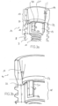
- FIG. 1 shows an implant 10.
- the implant 10 has a base body 9 with a thread 8 and a cutting edge 7 in a manner known per se.
- the implant 10 is inserted with the base body 9 into a jaw of a patient, so that a coronal end 16 of the implant 10 with a front edge 14 protrudes slightly from the bone or is slightly deeper, depending on the situation.
- Figure 2 shows a section through a central axis of the implant according to Figure 1 .
- the implant 10 Adjacent to the coronal end 16, the implant 10 has a receiving opening 15 for receiving an abutment (see Figure 4a ).
- the receiving opening 15 has a conical section 17 directly adjacent to the coronal end 16.
- a short cylindrical section 23 is directly adjacent to the conical section 17.
- An indexing section 18 is adjacent to the cylindrical section 23.
- the indexing section 18 is formed by a substantially cylindrical surface 19 into which three grooves 20 are arranged evenly distributed over the circumference.
- the grooves 20 extend radially outwards from the surface 19.
- the grooves have lateral groove surfaces 21 which engage with corresponding cam surfaces of an abutment (see Figure 4a ) or a driver or other auxiliary elements and thus form a rotation lock and enable the transmission of the insertion torque.
- a platform 22 is formed between the cylindrical section 23 and the indexing section 18.
- the abutment stands on this platform surface 22 (see Figure 4a ) with the cervical underside of its cams if the cams of the abutment are not exactly aligned with the grooves 20 of the implant 10. This defines an intermediate position.
- the implant 10 also has a threaded section 11.
- the abutment can be fixed to the implant using an abutment screw (see also Figure 7 ) in the implant 10.
- the abutment screw is designed with respect to the threaded portion 11 of the implant 10 such that the abutment screw does not engage with the threaded portion 11 when the abutment is in the intermediate position on the platform surface 22.
- Figures 3a and 3b show enlarged views of the implant 10 in the area of the conical section 17 and the indexing section 18 in section.
- the same reference numerals designate the same parts as in Figure 1 and 2 .
- the cone section 17 runs at a total cone angle of approximately 15° The following shows typical dimensions of an implant and an associated abutment with an implant diameter of 3.8 mm.
- the cone section 17 has a cone length k of 1.9 mm.
- the length z of the cylindrical section 23 is 0.4 mm.
- the indexing section 18 is relatively long in the axial direction compared to the cone section 17.
- the indexing length f is 1.8 mm.
- the grooves 20 introduced into the indexing section 18 have a groove depth t of at least 0.18 mm and a groove length n of at least 1.35 mm in the axial direction.
- the groove 20 therefore extends in the axial direction over at least 75% of the indexing length f.
- the indexing length f is 1.8 mm, almost equal to long as the cone length k. Due to this special choice of relatively long grooves, the groove surface 21 is relatively large even if the groove depth t is small. Deformation of the groove surface 21, for example due to contact with a screwing tool, is thus avoided.
- lower bottom 24 of the groove 20 is provided with a bevel. Due to the bevel on the bottom 24, the groove depth n is slightly smaller radially on the outside than on the radially inner edge of the groove.
- the bevel of the groove corresponds approximately to the bevel at the lower edge of the cam (bevel 125) of the implant.
- FIG 4a shows an abutment 110 according to the invention in a perspective view.
- the abutment 110 has a surface 112 which serves to directly or indirectly hold an artificial tooth. It is also conceivable to further process the surface 112 for this purpose, in particular to grind it.
- the abutment 110 has a connecting area 115 with which it can be inserted into the receiving area 15 of the implant 10 (see Figure 2 ).
- the connection area 115 has a conical section 117, to which an indexing section 118 adjoins towards the cervical end 116 of the abutment 110.
- the indexing section 118 consists of a substantially cylindrical surface 119, from which three cams 120 evenly distributed over the circumference adjoin radially outwards.
- the cams 120 define lateral cam surfaces 121, which can be brought into engagement with the groove surfaces 21 of the implant (see Figures 3a and 3b).
- the abutment 110 has an opening 113 in its front surface 122, onto which the end of a through hole 109 (see Figure 5 ) is formed. Through the opening 113, an abutment screw (see Figure 7 ) can be carried out.
- Figure 4b shows an enlarged view of the indexing section 118 of the abutment 110.
- the cams 120 have a cam length N of 1.55mm in the axial direction. Towards the cervical end 116 of the abutment 110, the cams 120 have an edge break 125. Between the cam 120 and the surface 119, an undercut 126 is made in the surface 119.
- the undercut 126 is mainly due to manufacturing reasons and allows a particularly precise manufacture of the surface 119 so that it can be manufactured with sufficient accuracy to serve as a guide surface.
- the cams 120 have a cam depth T of 0.15mm.
- the cylindrical surface 119 between the cams 120 extends from the lower end of the abutment 110 over the indexing section 118, but not over its entire height. Viewed in the axial direction, the cylindrical section 119 is closed off from the conical section 117 by an end surface 128. The end surface 128 is slightly bevelled with respect to a plane perpendicular to the axis (see also Figure 5 ). Further directed towards the conical section 117, the abutment 110 has a circumferential cylindrical surface 129. The cylindrical section 129 merges into the conical section 117 via an annular surface 129a running perpendicular to the axis.
- Figure 5 shows a section through the abutment 110 of Figures 4a and 4b along the central longitudinal axis.
- the abutment 110 has a bore 109 running in the axial direction.
- the bore 109 is provided with an internal thread 108, which serves to accommodate a disassembly tool.
- the cone section 117 has a total cone angle ⁇ of 15°.
- the cone section 117 has a cone length K of 1.9mm.
- the indexing section 118 has an indexing length F of 1.95mm.
- the cams have a cam length N of 1.55mm, which essentially corresponds to the length of the indexing section 118.
- a short cylindrical section 123 is arranged between the cone section 117 and the indexing section 118, which is due to the manufacturing process and does not fulfill any other function.
- Figure 6 shows a section through an abutment 110 inserted into an implant 10 along a plane perpendicular to the axis.
- the cams 120 are in engagement with the grooves 20 so that the cam surfaces 121 contact the groove surfaces 21.
- the outer diameter D2 of the surface 119 of the abutment 110 is essentially the same dimension as the inner diameter d2 of the contact surface 19 of the implant 10.
- the diameters D2 and d2 are both 2.1 mm and are tolerated such that the maximum play between the guide surfaces is no more than 0.06 mm.
- the minimum play is selected so that the abutment can be inserted into the receiving opening of the implant.
- the outer diameter D1 of the cams and the outer diameter d1 of the grooves are also essentially similar. However, a guide function is not mandatory here, so that a gap 30 can be created.
- the diameters D1 and d1 are typically 2.4mm and 2.45mm respectively.
- the cam depth T or the groove depth t results from the difference between the diameters D1 and D2 or d1 and d2.
- An undercut 126 is also introduced between the surface 119 and the groove 120 of the abutment 110. The undercut 126 is not taken into account for the definition of the cam depth T.
- the cams 120 and grooves 20 each have a cam or groove width of approximately 0.7 mm when viewed in the circumferential direction, with an outer diameter of the surface 119 of the abutment and an inner diameter of the surface 19 of the implant 10 of 2.1 mm.
- Figure 7 shows a cross-section of an abutment 110 inserted into the implant 10, which is secured with an abutment screw 111 in the threaded section 11 of the implant 10.
- the indexing sections 18, 118 of the implant 10 and abutment 110 are in engagement with one another, so that an anti-rotational lock is created. Due to the close tolerance of the surface 19, 119, the abutment 110 is guided in the implant 10 and is thus held precisely at its cervical end 116.
- the conical surfaces 117 of the abutment 110 or 17 of the implant 10 are tolerated in such a way that in any case there is contact between the conical surfaces 17, 117 in the area of the coronal end 16 of the implant.
- the abutment In the area where the abutment 110 emerges from the implant 10, the abutment has an outer diameter D11 which essentially corresponds to the inner diameter of the receiving opening 15 of the implant at its coronal end 16 (see also Figure 8 ). How Figure 8 As further shown, the front edge 14 of the implant 10 is not covered by the abutment 110.
- FIG 9 shows the implant 10 of Figure 1 , into which an auxiliary element designed as a gingiva former 310 is inserted.
- Gingiva formers are known to the person skilled in the art.
- the gingiva former 310 is designed in such a way that there is no contact between the cone section 17 and the gingiva former 310 in the receiving opening 15 of the implant and in particular in the cone section 17. Instead, the gingiva former rests with a contact surface 311 on the front edge 14 of the implant 10. Due to the cone gap 312 between the cone surface 17 of the implant and the gingiva former, damage to the cone surface 17 is avoided.
- the outer diameter D31 of the gingiva former in the area of the exit from the implant 10, i.e. adjacent to the front edge 14, is 3.5mm. It is therefore larger than the outer diameter D11 of 3.05mm of the abutment at the corresponding location (see Figures 7 and 8 ).
- Figures 10 and 11 show the implant 10 from Figure 1 , into which an auxiliary element designed as a molding element 410 is inserted.
- the impression element 410 has a contact surface 411 which, when inserted, rests on the front edge 14 of the implant (see also Figure 11 ) stands up.
- the impression element 410 is designed in such a way that, when inserted, a conical gap 412 is formed between the impression element and the conical section 17 of the implant 10.
- the axial or vertical position of the impression element 410 in relation to the implant 10 is precisely determined by the contact between the contact surface 411 and the front edge 14. There is no height shift due to tolerances in the cone angles and diameters.
- the impression element 410 also has an indexing section 418 (not shown in detail) which is essentially the same as the indexing section 118 of the abutment (see Figures 4a, 4b ).
- the diameter D41 of the impression element in the area of exit from the implant 10 is larger than the diameter D11 of the abutment at the same location (see Figures 7 and 8 ) and is essentially the same size or slightly smaller than the outer diameter D31 of the gingiva former at the corresponding location (see Figure 9 ).
- the implant 10 can also be temporarily provided with a temporary abutment 510, which does not touch the conical surface of the implant 10 and which strikes the front edge 14 of the implant 10 (see Fig.12 ).
- the implant 10 and the abutment 110 are manufactured and designed in a manner known per se. They are typically made of a biocompatible material such as titanium or ceramic. Depending on the tooth to be replaced, the implants and abutments are dimensioned differently, so that the dimensions given above are to be regarded as examples. For larger or smaller implants, the corresponding dimensions are reduced or increased evenly, so that the relationships between the individual lengths and diameters remain essentially unchanged.
- Implant diameter ⁇ 3.3 ⁇ 3.8 ⁇ 4.3 ⁇ 5 Implant Cone angle (total) ⁇ 15° 15° 15° 15° Cone length k 1.5 1.9 1.9 1.9 1.9 1.9 1.9 1.9 1.9 1.9 1.9 1.9 1.9 1.9 1.9 1.9 1.9 1.9 1.9 1.9 1.9 1.9 1.9 1.9 1.9 1.9 1.9 1.9 1.9 1.9 1.9 1.9 1.9 1.9 1.9 1.9 1.9 1.9 1.9 1.9 1.9 1.9 1.9 1.9 1.9 1.9 1.9 1.9 1.9 1.9 1.9 1.9 1.9 1.9 1.9 1.9 1.9 1.9 1.9 1.9 1.9 1.9 1.9 1.9 1.9 1.9 1.9 1.9 1.9 1.9 1.9 1.9 1.9 1.9 1.9 1.9 1.9 1.9 1.9 1.9 1.9 1.9 1.9 1.9 1.9 1.9 1.9 1.9 1.9 1.9 1.9 1.9 1.9 1.9 1.9 1.9 1.9 1.9 1.9 1.9 1.9 1.9 1.9 1.9 1.9 1.9 1.9 1.9 Cone
Landscapes
- Health & Medical Sciences (AREA)
- Oral & Maxillofacial Surgery (AREA)
- Orthopedic Medicine & Surgery (AREA)
- Dentistry (AREA)
- Epidemiology (AREA)
- Life Sciences & Earth Sciences (AREA)
- Animal Behavior & Ethology (AREA)
- General Health & Medical Sciences (AREA)
- Public Health (AREA)
- Veterinary Medicine (AREA)
- Dental Prosthetics (AREA)
- Prostheses (AREA)
Description
Die Erfindung betrifft ein Abutment für ein Zahnimplantat und eine Kombination aus einem Implantat und Abutment mit den Merkmalen des Oberbegriffs der unabhängigen Patentansprüche.The invention relates to an abutment for a dental implant and a combination of an implant and abutment with the features of the preamble of the independent patent claims.
Zahnimplantate und dazu gehörige Abutments sind in einer Vielzahl von verschiedenen Ausführungen bekannt. Das Zahnimplantat ist typischerweise durch einen im Wesentlichen zylinderförmigen Körper gebildet. Der Körper weist an seinem koronalen Ende eine Aufnahmeöffnung auf, in die ein so genanntes Abutment einsetzbar ist. Unter koronal wird hier und im Folgenden die Richtung bezeichnet, die gegen die Krone bzw. den aufzusetzenden Zahn gerichtet ist. In diesem Zusammenhang wird mit zervikal die Richtung bezeichnet, die gegen die Zahnwurzel hin gerichtet ist.Dental implants and the abutments associated with them are known in a variety of different designs. The dental implant is typically formed by a substantially cylindrical body. The body has a receiving opening at its coronal end into which a so-called abutment can be inserted. Coronal here and in the following refers to the direction that is directed towards the crown or the tooth to be attached. In this context, cervical refers to the direction that is directed towards the tooth root.
Das in die Aufnahmeöffnung einsetzbare Abutment dient in an sich bekannter Art und Weise zur direkten oder indirekten Aufnahme eines Zahnersatzes. Es ist bereits bekannt, die Aufnahmeöffnung im Implantat und eine entsprechende Gegenfläche konisch auszubilden. Auf diese Weise wird angestrebt, eine möglichst gute mechanische Verbindung sowie Dichtwirkung zwischen Abutment und Implantat zu erzielen, sodass kein Spalt entsteht, in dem sich Flüssigkeiten bzw. Bakterien festsetzen können. Solche konische Anordnungen sind aber mit verschiedenen Nachteilen behaftet. Beispielsweise entsteht bei der späteren Abformung eine Höhenverschiebung aufgrund von Toleranzen im Winkel und Durchmesser des Konus. Gleichzeitig ist aufgrund des Konus der Aussendurchmesser des Abutments im unteren Bereich kleiner als bei vergleichbaren Abutments oder Implantaten mit nicht konischen Abschnitten. Typischerweise befindet sich in diesem Bereich ein Indexierungsbereich zur Rotationssicherung oder Rotationspositionierung zwischen Abutment und Implantat. Solche Indexierungsbereiche bilden typischerweise in Umfangsrichtung einen Formschluss mit einer unrunden Kontur, z.B. durch einen Mehrkant oder durch Nuten und Nocken. Aufgrund der dünneren Wandstärke sind die Möglichkeiten bei der Gestaltung des Indexierungsbereichs reduziert. Insbesondere können sich auch Festigkeitsprobleme ergeben. Vor allem wenn der Indexierungsbereich im Implantat auch zum Kontakt mit einem Eindrehwerkzeug dient, um das Implantat einzudrehen, kann dies zu Problemen führen.The abutment that can be inserted into the receiving opening serves in a known manner to directly or indirectly accommodate a dental prosthesis. It is already known to make the receiving opening in the implant and a corresponding counter surface conical. In this way, the aim is to achieve the best possible mechanical connection and sealing effect between the abutment and the implant, so that no gap is created in which liquids or bacteria can settle. However, such conical arrangements have various disadvantages. For example, a height shift occurs during subsequent impression taking due to tolerances in the angle and diameter of the cone. At the same time, due to the cone, the outer diameter of the abutment in the lower area is smaller than with comparable abutments or implants with non-conical sections. Typically, there is an indexing area in this area to prevent rotation or to position the abutment in rotation. Such indexing areas typically form a positive connection in the circumferential direction with a non-circular contour, e.g. through a Polygonal or with grooves and cams. Due to the thinner wall thickness, the options for designing the indexing area are reduced. In particular, problems with strength can arise. This can lead to problems, especially if the indexing area in the implant is also used for contact with a screwing tool to screw in the implant.
Abutments und Implantate mit entsprechenden konischen Abschnitten sind beispielsweise aus
Es ist deshalb eine Aufgabe der vorliegenden Erfindung, die Nachteile des Bekannten zu vermeiden, insbesondere also ein ein Abutment und eine Kombination eines Abutments und eines Implantates zu schaffen, welche eine zuverlässige und feste Verbindung zwischen Implantat und Abutment gewährleisten, welche das Festsetzen von Bakterien in einem Spalt zwischen Implantat und Abutment möglichst verhindern und welche eine gute Kraftübertragung zwischen einem Eindrehwerkzeug und dem Implantat beim Eindrehen des Implantates sowie eine zuverlässige Abformung der Implantatsituation im Mund erlauben.It is therefore an object of the present invention to avoid the disadvantages of the known, in particular to create an abutment and a combination of an abutment and an implant which ensure a reliable and firm connection between implant and abutment, which prevent bacteria from settling in a gap between implant and abutment as far as possible and which allow good force transmission between a screwing tool and the implant when screwing in the implant as well as a reliable impression of the implant situation in the mouth.
Erfindungsgemäss werden diese und weitere Aufgaben mit einem einem Abutment und einer Kombination gemäss den Merkmalen des kennzeichnenden Teils der unabhängigen Patentansprüche gelöst.According to the invention, these and other objects are achieved with an abutment and a combination according to the features of the characterizing part of the independent patent claims.
Ein Zahnimplantat dient in bekannter Art und Weise zum Einsetzen in einen Kieferknochen. Das Implantat weist am koronalen Ende eine Aufnahmeöffnung für ein Abutment auf. Die Aufnahmeöffnung weist vom koronalen Ende her gesehen einen Konusabschnitt mit einer bestimmten Konuslänge und einen Indexierungsabschnitt mit einer bestimmten Indexierungslänge auf. Der Konusabschnitt weist einen Gesamtkonuswinkel im Bereich zwischen 6°-20° Grad, bevorzugt 10°-18° und weiter bevorzugt 15° auf. Im Zusammenspiel mit einem entsprechend geformten Konus am Abutment ergibt sich eine selbsthemmende Verbindung wenn das Abutment in das Implantat eingesetzt ist. Damit wird eine zusätzliche Stabilität der Verbindung erzielt. Weiter ist die Indexierungslänge mindestens 90%, bevorzugt je nach Implantatdurchmesser etwa 95% bis 125% der Konuslänge lang ausgebildet. Auf diese Weise ergibt sich trotz eines aufgrund des Konus reduzierten Aussendurchmessers am Abutment eine ausreichend grosse Stabilität in der Verbindung zwischen Abutment und Implantat. Ausserdem wird eine genügend grosse Eingriffsfläche für ein Eindrehwerkzeug zur Verfügung gestellt. Der Indexierungsabschnitt dient zur Rotationspositionierung und Rotationssicherung zwischen Abutment und Implantat und gleichzeitig auch als Eingriffsfläche für ein Einbringwerkzeug. Bevorzugt ist der Indexierungsabschnitt in Achsrichtung gesehen mindestens 1.6 mm lang. Grundsätzlich ist es denkbar, den Indexierungsabschnitt in an sich bekannter Art und Weise mit einem Mehrkant oder anderen nicht runden Konturen auszubilden. Bevorzugt ist jedoch ein Indexierungsabschnitt, der wie nachstehend beschrieben mit einer Nut-Nockenverbindung ausgebildet ist.A dental implant is used in a known manner for insertion into a jawbone. The implant has a receiving opening for an abutment at the coronal end. The receiving opening has a cone section with a specific cone length and an indexing section with a specific indexing length when viewed from the coronal end. The cone section has a total cone angle in the range between 6°-20°, preferably 10°-18° and more preferably 15°. In conjunction with a correspondingly shaped cone on the abutment, a self-locking connection is created when the abutment is inserted into the implant. This provides additional stability to the connection. Furthermore, the indexing length is at least 90%, preferably around 95% to 125% of the cone length depending on the implant diameter. In this way, despite an outer diameter on the abutment being reduced due to the cone, there is sufficient stability in the connection between the abutment and the implant. In addition, a sufficiently large engagement surface is provided for a screwing-in tool. The indexing section is used for rotational positioning and rotational locking between the abutment and the implant and at the same time also as an engagement surface for an insertion tool. Preferably, the indexing section is at least 1.6 mm long in the axial direction. In principle, it is conceivable to form the indexing section in a manner known per se with a polygon or other non-round contours. However, an indexing section is preferred which is formed with a groove-cam connection as described below.
Der Indexierungsabschnitt weist bervorzugt eine Oberfläche auf, in welcher wenigstens eine sich in radialer Richtung nach Aussen erstreckende Nut mit einer bestimmten Nutlänge angeordnet ist. Die Nut ist mit einem Nocken eines Abutments in Eingriff bring-bar. Typischerweise ist dabei die Oberfläche wenigstens teilweise zylindrisch ausgebildet. Gleichzeitig ist sie so bemessen und toleriert, dass sie eine Führungsfläche für ein bestimmungsgemäss eingesetztes Abutment bildet.The indexing section preferably has a surface in which at least one groove extending outwards in a radial direction and having a certain groove length is arranged. The groove can be brought into engagement with a cam of an abutment. Typically, the surface is at least partially cylindrical. At the same time, it is designed so that dimensioned and tolerated to provide a guide surface for a properly inserted abutment.
Weiter bevorzugt ist es, dass sich die Nutlänge im Wesentlichen über die ganze Länge des Indexierungsabschnittes erstreckt, insbesondere über mindestens 70%. Auf diese Weise lässt sich der Kontakt zwischen der Eingriffsfläche der Nut und einer entsprechenden Eingriffsfläche an einem Nocken eines Eindrehwerkzeuges oder eines Abutments maximieren, sodass Eindrehkräfte oder - Momente ohne plastische Deformation übertragen werden können bzw. sodass die pro Flächeneinheit eingeleitete Kraft miniert werden kann. Diese Verformung hätte einen Einfluss auf die Genauigkeit der Abformung und Positionierung des Abutments. Der gegen das untere Ende des Implantates gerichtete Boden der Nut ist bevorzugt abgeschrägt. Der Winkel der Abschrägung entspricht insbesondere bevorzugt dem Winkel einer entsprechenden Anphasung an einen Nocken eines Abutments.It is further preferred that the groove length extends substantially over the entire length of the indexing section, in particular over at least 70%. In this way, the contact between the engagement surface of the groove and a corresponding engagement surface on a cam of a screwing tool or an abutment can be maximized, so that screwing forces or moments can be transmitted without plastic deformation or so that the force introduced per unit area can be minimized. This deformation would have an influence on the accuracy of the impression and positioning of the abutment. The bottom of the groove directed towards the lower end of the implant is preferably beveled. The angle of the bevel particularly preferably corresponds to the angle of a corresponding chamfer on a cam of an abutment.
Bevorzugt schliesst sich in zervikaler Richtung an den Indexierungsabschnitt des Implantats unmittelbar ein Gewindeabschnitt zur Aufnahme einer Abutmentschraube an. Mit anderen Worten heisst dies, dass sich an den Formschlussabschluss im Implantat kein weiterer Bereich anschliesst, der zur Aufnahme oder Führung des Abutments dient.Preferably, the indexing section of the implant is directly connected in the cervical direction to a threaded section for receiving an abutment screw. In other words, this means that there is no further area adjacent to the form-fitting closure in the implant that serves to receive or guide the abutment.
Besonders bevorzugt hat die Oberfläche des Indexierungsabschnittes einen Aussendurchmesser, der grösser ist als 80% des Aussendurchmessers der Nut. Damit kann der Aussendurchmesser eines entsprechenden Indexierungsabschnitts eines Abutments so gross wie möglich ausgestaltet werden. Gleichzeitig sollte der Aussendurchmesser des Indexierungsabschnittes sich aber nicht zu sehr am Aussendurchmesser der Nut annähern, damit eine ausreichend grosse Nuttiefe gewährleistet bleibt.Particularly preferably, the surface of the indexing section has an outer diameter that is larger than 80% of the outer diameter of the groove. This allows the outer diameter of a corresponding indexing section of an abutment to be designed as large as possible. At the same time, however, the outer diameter of the indexing section should not be too close to the outer diameter of the groove in order to ensure a sufficiently large groove depth.
Weiter bevorzugt weist die Nut eine radial verlaufende Nutfläche (bzw. beidseitig eine radial verlaufende Nutfläche) auf, welche grösser als 0,22 mm2 ausgebildet ist.More preferably, the groove has a radially extending groove surface (or a radially extending groove surface on both sides) which is larger than 0.22 mm2.
Gleichzeitig ist bevorzugt die Nutlänge grösser als 500 % der Nuttiefe. Als Nuttiefe wird die Distanz zwischen der Oberfläche des Indexierungsabschnittes und dem Nutaussendurchmesser verstanden.At the same time, the groove length is preferably greater than 500% of the groove depth. The groove depth is the distance between the surface of the indexing section and the groove outer diameter.
Gemäss einer weiteren bevorzugten Ausführungsform ist der kleine Konusdurchmesser (d.h. der Durchmesser am zervikalen Ende des Konusabschnittes) grösser oder gleich gross als der Nutaussendurchmesser. Damit wird eine Plattform gebildet, die beim Einsetzen des Abutments eine Zwischenposition definiert.According to a further preferred embodiment, the small cone diameter (i.e. the diameter at the cervical end of the cone section) is larger than or equal to the groove outer diameter. This forms a platform which defines an intermediate position when inserting the abutment.
Weiter bevorzugt ist zwischen dem Konusabschnitt und dem Indexierungsabschnitt des Implantates eine umlaufende Plattformfläche gebildet. Die Nut erstreckt sich dabei in axialer Richtung bis hin zu dieser Plattformfläche. Eine solche Plattformfläche erlaubt es, eine Zwischenposition zu definieren. Ein Abutment kann in das Implantat eingesetzt werden, bis die Unterseiten der entsprechenden Nocken des Abutments auf der Plattformfläche aufliegen. Durch Drehen des Abutments in eine Position, in der die Nocken am Abutment mit den Nuten im Implantat ausgerichtet sind, kann das Abutment dann in die gewünschte Endposition gebracht werden. Der Einsetzvorgang bestehend aus den Schritten "axiales Einführen", "drehen in Umfangsrichtung" und "axiales bewegen in Endposition" ist für den Benutzer besonders intuitiv. Das Einsetzen in einer nicht gewünschten Zwischenposition wird damit verhindert.It is also preferred that a circumferential platform surface is formed between the cone section and the indexing section of the implant. The groove extends in the axial direction up to this platform surface. Such a platform surface makes it possible to define an intermediate position. An abutment can be inserted into the implant until the undersides of the corresponding cams of the abutment rest on the platform surface. By rotating the abutment into a position in which the cams on the abutment are aligned with the grooves in the implant, the abutment can then be brought into the desired final position. The insertion process consisting of the steps "axial insertion", "rotation in the circumferential direction" and "axial movement to the final position" is particularly intuitive for the user. Insertion in an undesirable intermediate position is thus prevented.
Ein erster Aspekt der Erfindung betrifft ein Abutment für ein Zahnimplantat mit den Merkmalen von Anspruch 1. Das Abutment weist eine Oberfläche zum direkten oder indirekten Aufnehmen eines Zahnersatzes auf. Das Abutment weist ausserdem einen Verbindungsbereich zur Verbindung mit dem Implantat auf. Der Verbindungsbereich ist typischerweise in die vorstehend genannte Aufnahmeöffnung des Implantates einsetzbar. Das Abutment ist mittels einer Abutmentschraube in an sich bekannter Art und Weise im Implantat fixierbar. Der Verbindungsbereich des Abutments weist einen Konusabschnitt mit einer bestimmten Konuslänge auf. An den Verbindungsbereich schliesst sich in zervikaler Richtung ein Indexierungsbereich mit einer bestimmten Indexierungslänge an. Der Konusabschnitt des Abutments weist einen Gesamtkonuswinkel von 6°-20°, bevorzugt 10°-18° und besonders bevorzugt 15° Grad auf. Die Indexierungslänge des Abutments beträgt mindestens 90%, bevorzugt 95% bis 125% der Konuslänge des Abutments. Im Zusammenspiel mit den wie vorstehend beschriebenen Abutments ergeben sich damit besonders stabile Verbindungen. Bevorzugt beträgt dabei die Indexierungslänge mindestens 1.6 mm. Der Indexierungsabschnitt wird gegen das zervikale Ende hin durch das Ende der Formschlusselemente begrenzt. Gegen das koronale Ende hin wird der Indexierungsabschnitt durch das Ende eines im Wesentlichen zylindrischen Abschnittes begrenzt, auf oder in dem die Formschlusselemente angebracht sind. Zervikal an den Indexierungsabschnitt anschliessend sind keine weiteren Führungsabschnitte oder Führungselemente vorgesehen.A first aspect of the invention relates to an abutment for a dental implant with the features of claim 1. The abutment has a surface for directly or indirectly receiving a dental prosthesis. The abutment also has a connection area for connection to the implant. The connection area can typically be inserted into the above-mentioned receiving opening of the implant. The abutment can be fixed in the implant by means of an abutment screw in a manner known per se. The connection area of the abutment has a conical section with a certain conical length. An indexing area with a certain indexing length adjoins the connection area in the cervical direction. The conical section of the abutment has a total conical angle of 6°-20°, preferably 10°-18° and particularly preferably 15°. The indexing length of the abutment is at least 90%, preferably 95% to 125% of the conical length of the abutment. In conjunction with the abutments as described above, this results in particularly stable connections. The indexing length is preferably at least 1.6 mm. The indexing section is limited towards the cervical end by the end of the form-locking elements. Towards the coronal end, the indexing section is limited by the end of a substantially cylindrical section on or in which the form-locking elements are attached. No further guide sections or guide elements are provided cervically adjacent to the indexing section.
Das Abutment weist im Indexierungsabschnitt eine Oberfläche auf, von der sich radial nach Aussen wenigstens ein Nocken erstreckt. Der Nocken ist mit den entsprechenden Nuten eines Implantates in Eingriff bringbar. Diese Oberfläche des Abutments ist wenigstens teilweise zylindrisch ausgebildet. Sie ist ausserdem so bemessen und toleriert, dass sie eine Führungsfläche für eine Oberfläche des Indexierungsabschnittes eines Implantates bildet, wenn das Abutment bestimmungsgemäss in das Implantat eingesetzt wird. Das Abutment kann dadurch kürzer ausgebildet werden als beispielsweise das in
Typischerweise wird die entsprechende Führungsfläche am Abutment und die Führungsfläche am Implantat bei einem Durchmesser von ca. 2 bis 3mm mit einer solchen Toleranz gefertigt, dass das maximale Spiel zwischen den Oberflächen weniger als 0.06 mm beträgt.Typically, the corresponding guide surface on the abutment and the guide surface on the implant are manufactured at a diameter of approximately 2 to 3 mm with such a tolerance that the maximum clearance between the surfaces is less than 0.06 mm.
Die Nocken erstrecken sich bevorzugt im Wesentlichen über den ganzen Bereich des Indexierungsabschnittes. Als im Wesentlichen der ganze Indexierungsbereich wird eine Länge von mindestens 70 % verstanden. Auf diese Weise wird die Kontaktfläche zwischen den Nuten und den Nocken maximiert, wodurch sich eine bessere Kraftverteilung und eine stabilere Verbindung ergibt. Die Nocken am Abutment können aber auch etwas länger, typischerweise mindestens 75% des Indexierungsbereichs ausgebildet sein. Die zylindrische Fläche zwischen den Nocken kann an ihrem oberen Ende, d. h. gegen den Konusabschnitt hin, eine Endfläche aufweisen, welche bezogen auf eine Ebene senkrecht zur Achse abgeschrägt ist. Die Abschrägung beträgt bevorzugt 40° bis 50°, insbesondere etwa 45°. Ausserdem bevorzugt schliesst sich in Richtung des Konusabschnitts an diese Abschlussfläche eine umlaufende zylindrische Fläche an. Der Aussendurchmesser dieser zylindrischen Fläche entspricht insbesondere dem Aussendurchmesser des Nockens auf dem Abutment, so dass sich umlaufend eine Fläche mit konstantem Zylinderradius ergibt.The cams preferably extend essentially over the entire area of the indexing section. Essentially the entire indexing area is understood to mean a length of at least 70%. In this way, the contact area between the grooves and the cams is maximized, resulting in better force distribution and a more stable connection. The cams on the abutment can also be somewhat longer, typically at least 75% of the indexing area. The cylindrical surface between the cams can have an end surface at its upper end, i.e. towards the conical section, which is beveled with respect to a plane perpendicular to the axis. The bevel is preferably 40° to 50°, in particular approximately 45°. In addition, a circumferential cylindrical surface preferably adjoins this end surface in the direction of the conical section. The outer diameter of this cylindrical The surface corresponds in particular to the outer diameter of the cam on the abutment, so that a surface with a constant cylinder radius is created all around.
Gemäss einer weiteren bevorzugten Ausführungsform weist das Abutment in zervikaler Richtung anschliessend an den Indexierungsabschnitt am zervikalen Ende eine Stirnfläche mit einer Öffnung auf. Durch diese Öffnung ist ein Gewindeabschnitt einer Abutmentschraube durchführbar. Mit anderen Worten bedeutet dies, dass der Indexierungsabschnitt in zervikaler Richtung das letzte Element des Abutments bildet (mit Ausnahme der nicht mit dem Abutmentkörper einstückig ausgebildeten Abutmentschraube).According to a further preferred embodiment, the abutment has a front surface with an opening in the cervical direction adjacent to the indexing section at the cervical end. A threaded section of an abutment screw can be passed through this opening. In other words, this means that the indexing section in the cervical direction forms the last element of the abutment (with the exception of the abutment screw which is not formed in one piece with the abutment body).
Weiter bevorzugt ist der Aussendurchmesser der Oberfläche des Indexierungsabschnittes des Abutments grösser als 80% des Nockenaussendurchmessers. Dadurch wird sichergestellt, dass die Oberfläche des Indexierungsabschnittes, welche wie vorstehend beschrieben gleichzeitig eine Führungsfläche bildet, möglichst gross ausgebildet sein kann. Zusätzlich haben gleiche Fertigungstoleranzen bei grösseren Dimensionen weniger Einfluss auf das Spiel.It is also preferred that the outer diameter of the surface of the indexing section of the abutment is greater than 80% of the cam outer diameter. This ensures that the surface of the indexing section, which at the same time forms a guide surface as described above, can be as large as possible. In addition, the same manufacturing tolerances have less influence on the play with larger dimensions.
Der Nocken weist weiter bevorzugt eine radial verlaufende Nockenfläche auf, die grösser als 0.22 mm2 ist. Die Nockenlänge ist dabei bevorzugt wenigstens 500 % grösser als die Nockentiefe. Unter Nockentiefe wird der Abstand zwischen Nockenaussendurchmesser und Oberfläche des Indexierungsabschnittes des Abutments verstanden. Indem die Nocken mit einer ausreichend grossen Länge ausgebildet werden, kann die Nockenfläche, welche eine Kontaktfläche für Nuten des Implantates bildet trotz der geringen Nockentiefen, ausreichend gross gewählt werden, um das Eindrehmoment beim Inserieren der Implantate zu übertragen.The cam further preferably has a radially extending cam surface that is larger than 0.22 mm2. The cam length is preferably at least 500% larger than the cam depth. Cam depth is understood to be the distance between the cam outer diameter and the surface of the indexing section of the abutment. By designing the cams with a sufficiently large length, the cam surface, which forms a contact surface for the grooves of the implant, can be Cam depths must be chosen to be sufficiently large to transmit the insertion torque when inserting the implants.
Der Durchmesser des Konus ist an seinem zervikalen Ende grösser oder gleich gross als der Durchmesser der Nocken.The diameter of the cone at its cervical end is larger than or equal to the diameter of the cams.
Ausserdem weist der Nocken an seinem zervikalen Ende bevorzugt einen Kantenbruch auf. Durch einen solchen Kantenbruch wird das Einführen der Nocken in die Nuten des Implantats erleichtert. Der Kantenbruch bildet eine Einführhilfe.In addition, the cam preferably has a broken edge at its cervical end. Such a broken edge makes it easier to insert the cam into the grooves of the implant. The broken edge acts as an insertion aid.
Weiter bevorzugt weist das Abutment ein Emergenzprofil mit einer bestimmten Formgebung auf: An den Konusabschnitt des Abutments, welcher aus dem Implantat austritt, schliesst sich ein kurzer zylindrischer Abschnitt und dann ein in einer Schnittebene durch die Achse des Abutments gesehen konkaver und anschliessend ein konvexer Bereich an, welcher der natürlichen Zahnform nachempfunden ist.The abutment further preferably has an emergence profile with a specific shape: the conical section of the abutment, which emerges from the implant, is followed by a short cylindrical section and then a concave area, seen in a sectional plane through the axis of the abutment, and then a convex area, which is modeled on the natural tooth shape.
Weiter bevorzugt ist die Oberfläche des Indexierungsabschnittes des Abutments nicht vollständig zylindrisch ausgebildet. Bevorzugt befinden sich zwischen den Nockenflächen des Nockens und der als Führungsfläche dienenden Oberfläche Hinterschnitte. Mit solchen Hinterschnitten ist eine besonders präzise Herstellung des Indexierungsabschnitts resp. der Führungsoberfläche am Abutment möglich.Furthermore, the surface of the indexing section of the abutment is preferably not completely cylindrical. There are preferably undercuts between the cam surfaces of the cam and the surface serving as a guide surface. With such undercuts, a particularly precise manufacture of the indexing section or the guide surface on the abutment is possible.
Das mit einer axialen Bohrung versehene Abutment kann im Bereich der Bohrung mit einem zusätzlichen Gewinde versehen sein. Das Gewinde dient zur Aufnahme eines Demontage-Tools. Weil der Konuswinkel so gewählt ist, dass sich bei eingesetztem Abutment eine Selbsthemmung zwischen der Konusflächen des Abutments und des Implantates ergibt, ist es unter Umständen möglich, dass das Abutment nicht ohne weiteres entfernt werden kann. Dank diesem Gewinde kann zum Entkoppeln des Abutments ein Demontage-Tool im Abutment befestigt werden.The abutment with an axial bore can be provided with an additional thread in the area of the bore. The thread is used to accommodate a disassembly tool. Because the cone angle is selected in such a way that when the abutment is inserted, there is a self-locking effect between the conical surfaces of the abutment and the implant, it is possible that the abutment cannot be easily removed. Thanks to this thread, a disassembly tool can be attached to the abutment to decouple the abutment.
Ein weiterer Aspekt der Erfindung betrifft eine Kombination aus einem wie vorstehend beschriebenen Implantat und einem wie vorstehend beschriebenen Abutment. Die Indexierungsabschnitte von Implantat und Abutment und die Konusabschnitte von Implantat und Abutment sind dabei so bemessen und geformt, dass bei in das Implantat eingesetztem Abutment die Konusabschnitte sich wenigstens teilweise gegenseitig berühren und dass die Indexierungsabschnitte im gegenseitigen Eingriff stehen. Die Flächen, über die die Konusabschnitte in Kontakt stehen, werden dabei soweit möglich im Rahmen der Toleranzen maximiert.A further aspect of the invention relates to a combination of an implant as described above and an abutment as described above. The indexing sections of the implant and abutment and the conical sections of the implant and abutment are dimensioned and shaped such that when the abutment is inserted into the implant, the conical sections at least partially touch each other and that the indexing sections are in mutual engagement. The areas over which the conical sections are in contact are maximized as far as possible within the tolerances.
Besonders bevorzugt sind die Konusabschnitte an Abutment und Implantat so toleriert, dass bei jeder denkbaren Paarung zwischen Implantat und das dazu gehörige Abutment im Rahmen der Toleranzen ein Kontakt zwischen den Konusabschnitten am koronalen Rand des Konusabschnittes des Implantates erfolgt. Ein in der Realität nie auszuschliessender Spalt zwischen Abutment und Implantat aufgrund von Toleranzen im Konuswinkel wird sich dann in jedem Fall nicht am koronalen Rand sondern nach innen versetzt ausbilden. Damit wird verhindert, dass sich Flüssigkeiten in einem entsprechenden Spalt festsetzen.It is particularly preferred that the cone sections on the abutment and implant are toleranced in such a way that, within the tolerances, contact occurs between the cone sections at the coronal edge of the cone section of the implant for every conceivable pairing between the implant and the associated abutment. A gap between the abutment and the implant, which can never be ruled out in reality due to tolerances in the cone angle, will then in any case not form at the coronal edge but offset inwards. This prevents liquids from settling in a corresponding gap.
Aufgrund des Kontaktes zwischen den Konusabschnitten im Bereich des koronalen Randes wird ausserdem eine besonders stabile Befestigung des Abutments im Implantat erzielt. Es besteht gewissermassen eine zwei Punkt Abstützung einerseits am oberen koronalen Rand und andererseits im Bereich der Führungsflächen zwischen den Nuten bzw. den Nocken.The contact between the conical sections in the area of the coronal edge also ensures that the abutment is particularly firmly secured in the implant. There is a two-point support, on the one hand at the upper coronal edge and on the other hand in the area of the guide surfaces between the grooves or cams.
Weiter bevorzugt sind die Oberflächen der Indexierungsabschnitte zwischen den Nocken des Abutments einerseits und zwischen den Nuten des Implantates andererseits so bemessen, dass das Abutment durch Kontakt zwischen den Oberflächen der Indexierungsabschnitte im Implantat geführt ist. Typischerweise sind die Oberflächen wie folgt bemessen, dass bei Führungsflächen mit einem Durchmesser von 2 bis 3mm, typischerweise 2.1mm, das maximale Spiel zwischen den Führungsflächen 0.06mm beträgt.More preferably, the surfaces of the indexing sections between the cams of the abutment on the one hand and between the grooves of the implant on the other hand are dimensioned such that the abutment is guided in the implant by contact between the surfaces of the indexing sections. Typically, the surfaces are dimensioned such that with guide surfaces with a diameter of 2 to 3 mm, typically 2.1 mm, the maximum play between the guide surfaces is 0.06 mm.
Gemäss noch einer weiteren bevorzugten Ausführungsform weist das Abutment eine Abutmentschraube auf, deren Länge und insbesondere deren Anordnung des Gewindes so bemessen ist, dass die Abutmentschraube nicht in Eingriff mit einem Gewindeabschnitt im Implantat gelangen kann, solange das Abutment mit der Stirnfläche seiner Nocken am zervikalen Ende auf der Plattform des Implantates aufliegt. Auf diese Weise wird verhindert, dass versehentlich das Abutment durch Festziehen einer Abutmentschraube im Implantat befestigt wird, bevor das Abutment die korrekte Position erreicht hat.According to yet another preferred embodiment, the abutment has an abutment screw, the length and in particular the arrangement of the thread of which is such that the abutment screw cannot engage with a threaded section in the implant as long as the abutment rests on the platform of the implant with the front surface of its cams at the cervical end. In this way, it is prevented that the abutment is accidentally secured in the implant by tightening an abutment screw before the abutment has reached the correct position.
Die Erfindung wird im Folgenden anhand der Zeichnungen und in Ausführungsbeispielen näher erläutert. Es zeigen:
-
Figur 1
Seitenansicht eines Implantats -
Figur 2
Schnitt durch das Implantat gemässFigur 1 entlang einer Mittenlängs-Achse -
Figuren 3a und 3b
vergrösserte Darstellungen des Implantats ausFigur 1 im Bereich einer Aufnahmeöffnung im Schnitt -
Figur 4a
perspektivische Darstellung eines erfindungsgemässen Abutments -
Figur 4b
vergrösserte Darstellung des Abutments ausFigur 4a in einem Verbindungsbereich -
Figur 5
Schnitt durch das Abutment gemässFigur 4a entlang einer Mittenlängs-Achse -
Figur 6
Schnitt durch ein Implantat und ein erfindungsgemässes Abutment in einem Indexierungsbereich entlang einer Ebene senkrecht zur Achse -
Figur 7
Schnitt durch ein erfindungsgemässes Abutment und ein Implantat entlang einer Mittenlängs-Ebene -
Figur 8
vergrösserte Darstellung eines erfindungsgemässen Abutments in einem Implantat im Schnitt entlang einer Mittenlängs-Ebene in einem Verbindungsbereich -
Figur 9
Schnitt durch ein Implantat mit einem Gingiva-Former entlang einer Mittenlängs-Ebene -
Figur 10
Schnitt durch ein Implantat mit einem Abformelement entlang einer Mittenlängs-Ebene, -
Figur 11
vergrösserte Darstellung des Abformelements und des Implantates ausFigur 10 im Bereich des Konusabschnittes des Implantates und -
Figur 12
Schnitt durch ein Implantat mit einem Provisoriumsabutment entlang einer Mittenlängs-Ebene.
-
Figure 1
Side view of an implant -
Figure 2
Section through the implant according toFigure 1 along a central longitudinal axis -
Figures 3a and 3b
enlarged images of the implant fromFigure 1 in the area of a receiving opening in section -
Figure 4a
Perspective view of an abutment according to the invention -
Figure 4b
enlarged view of the abutment fromFigure 4a in a connection area -
Figure 5
Section through the abutment according toFigure 4a along a central longitudinal axis -
Figure 6
Section through an implant and an abutment according to the invention in an indexing area along a plane perpendicular to the axis -
Figure 7
Section through an abutment according to the invention and an implant along a central longitudinal plane -
Figure 8
enlarged view of an abutment according to the invention in an implant in section along a central longitudinal plane in a connection area -
Figure 9
Section through an implant with a gingiva former along a mid-longitudinal plane -
Figure 10
Section through an implant with an impression element along a central longitudinal plane, -
Figure 11
enlarged view of the impression element and the implant fromFigure 10 in the area of the cone section of the implant and -
Figure 12
Section through an implant with a temporary abutment along a mid-longitudinal plane.
Zwischen dem zylindrischen Abschnitt 23 und dem Indexierungsabschnitt 18 ist eine Plattform 22 gebildet. Auf dieser Plattformfläche 22 steht das Abutment (siehe
Im Nachfolgenden werden typische Dimensionen eines Implantats und eines zugehörigen Abutments mit einem Implantatdurchmesser von 3.8mm wieder gegeben. Der Konusabschnitt 17 weist eine Konuslänge k von 1.9 mm auf. Die Länge z des zylindrischen Abschnitts 23 beträgt 0.4mm.
The following shows typical dimensions of an implant and an associated abutment with an implant diameter of 3.8 mm. The
Der Indexierungsabschnitt 18 ist im Vergleich zum Konusabschnitt 17 verhältnismässig lang in axialer Richtung ausgebildet. Die Indexierungslänge f beträgt 1.8mm.The
Die in den Indexierungsabschnitt 18 eingebrachten Nuten 20 weisen eine Nuttiefe t von mind. 0.18mm und in axialer Richtung eine Nutlänge n von mind. 1.35 mm auf. Die Nut 20 erstreckt sich daher in axialer Richtung über mindestens 75% der Indexierungslänge f. Die Indexierungslänge f ist mit 1.8mm fast gleich lang wie die Konuslänge k ausgebildet. Aufgrund dieser speziellen Wahl von verhältnismässig langen Nuten wird die Nutfläche 21 verhältnismässig gross ausgebildet auch wenn die Nuttiefe t gering ist. Verformungen der Nutfläche 21 beispielsweise aufgrund eines Kontakts mit einem Eindrehwerkzeug werden dadurch vermieden.The
Am in
Am zervikalen Ende 116 weist das Abutment 110 in seiner Stirnfläche 122 eine Öffnung 113 auf welche das Ende einer durchgehenden Bohrung 109 (siehe
Die zylindrische Oberfläche 119 zwischen den Nocken 120 erstreckt sich vom unteren Ende des Abutments 110 über den Indexierungsabschnitt 118, allerdings nicht über dessen ganze Höhe. In axialer Richtung gesehen wird der zylindrische Abschnitt 119 gegen den Konusabschnitt 117 hin durch eine Endfläche 128 abgeschlossen. Die Endfläche 128 ist bezogen auf eine Senkrechtebene zur Achse leicht abgeschrägt (siehe auch
Der Konusabschnitt 117 weist einen Gesamtkonuswinkel β von 15° Grad auf. Der Konusabschnitt 117 weist eine Konuslänge K von 1.9mm auf. Der Indexierungsabschnitt 118 weist eine Indexierungslänge F von 1.95mm auf. Die Nocken weisen eine Nockenlänge N von 1.55mm auf, die im Wesentlichen der Länge des Indexierungsabschnittes 118 entspricht. Zwischen dem Konusabschnitt 117 und dem Indexierungsabschnitt 118 ist ein kurzer zylindrischer Abschnitt 123 angeordnet, der herstelltechnisch bedingt ist und keine weitere Funktion erfüllt.The
Die Nocken 120 stehen mit den Nuten 20 im Eingriff, sodass die Nockenflächen 121 die Nutflächen 21 kontaktieren. Der Aussendurchmesser D2 der Oberfläche 119 des Abutments 110 ist im Wesentlichen gleich dimensioniert wie der Innendurchmesser d2 der Kontaktfläche 19 des Implantates 10. Dadurch ist die Oberfläche 119 des Abutments zwischen den Nocken 120 an der Oberfläche 19 des Implantates 10 zwischen den Nuten 20 geführt. Die Durchmesser D2 und d2 betragen beide 2.1 mm und sind so toleriert, dass das maximale Spiel zwischen den Führungsoberflächen nicht mehr als 0.06mm beträgt. Ausserdem ist das Mindestspiel so gewählt, dass das Abutment in den Aufnahmeöffnung des Implantates einführbar ist.The
Der Aussendurchmesser D1 der Nocken bzw. der Aussendurchmesser d1 der Nuten ist ebenfalls im Wesentlichen ähnlich ausgebildet. Hier ist allerdings eine Führungsfunktion nicht zwingend, sodass sich ein Spalt 30 einstellen kann. Die Durchmesser D1 und d1 betragen typischerweise 2.4mm bzw. 2.45mm. Die Nockentiefe T bzw. die Nuttiefe t ergibt sich aus der Differenz zwischen den Durchmessern D1 und D2 bzw. d1 und d2. Zwischen der Oberfläche 119 und der Nut 120 des Abutments 110 ist ausserdem ein Hinterschnitt 126 eingebracht. Der Hinterschnitt 126 wird zur Definition der Nockentiefe T nicht berücksichtigt.The outer diameter D1 of the cams and the outer diameter d1 of the grooves are also essentially similar. However, a guide function is not mandatory here, so that a
Die Nocken 120 bzw. Nuten 20 weisen in Umfangsrichtung gesehen bei einem Aussendurchmesser der Oberfläche 119 des Abutments bzw. einem Innendurchmesser der Oberfläche 19 des Implantates 10 von 2.1mm jeweils eine Nocken- bzw. Nutenbreite von ca. 0.7mm auf.The
Im Bereich des Austritts des Abutments 110 aus dem Implantat 10 weist das Abutment einen Aussendurchmesser D11 auf, der im Wesentlichen den Innendurchmesser der Aufnahmeöffnung 15 des Implantates an seinem koronalen Ende 16 entspricht (siehe auch
Das Abformelement 410 weist eine Kontaktfläche 411 auf, welche in eingesetztem Zustand auf dem Stirnrand 14 des Implantates (siehe auch
Das Abformelement 410 weist im übrigen einen nicht weiter dargestellten Indexierungsabschnitt 418 auf, der im Wesentlichen gleich ausgebildet ist wie der Indexierungsabschnitt 118 des Abutments (siehe
Der Durchmesser D41 des Abformelements im Bereich des Austritts aus dem Implantat 10 ist grösser als der Durchmesser D11 des Abutments an der gleichen Stelle (siehe
Statt dem Implantat 10 und einem Abutment 110 wie in
Das Implantat 10 und das Abutment 110 sind in an sich bekannter Art und Weise hergestellt und ausgebildet. Typischerweise bestehen sie aus einem biokompatiblen Material wie Titan oder Keramik. Je nach zu ersetzendem Zahn sind die Implantate und Abutments unterschiedlich dimensioniert, sodass die vorstehend angegebenen Masse als beispielhaft zu betrachten sind. Bei grösseren oder kleineren Implantaten werden die entsprechenden Dimensionen gleichmässig reduziert oder vergrössert, sodass die Relationen zwischen den einzelnen Längen und Durchmessern im Wesentlichen unverändert bleiben.The
Die Gesamtkonuswinkel bleiben unabhängig von der Implantatgrösse immer gleich, jedoch kann die Konuslänge bei unterschiedlichen Durchmessern variieren.The overall cone angles always remain the same regardless of the implant size, but the cone length can vary with different diameters.
Exemplarisch sind die einzelnen Masse (in mm bzw. mm2) für Implantate mit den Durchmessern 3.3mm, 3.8mm (siehe auch vorstehende Beschreibung), 4.3mm und 5mm in der nachfolgenden Tabelle wieder gegeben.
Claims (20)
- Abutment (110) for a dental implant (10),with a surface (112) for receiving a tooth replacement either directly or indirectly, andwith a connection area (115) for connection to the dental implant (10),wherein the connection area (115) has a cone section (117) with a cone length (K) which, in the cervical direction, is adjoined by an indexing section (118) with an indexing length (F), wherein the cone section (117) has a total cone angle (β) of 6 to 20°, preferably 10° to 18°, particularly preferably 15°, characterized in that the indexing length (F) is at least 70% of the cone length (K), and in that the indexing section (118) is formed by a substantially cylindrical surface (119), wherein the cylindrical surface (119) is dimensioned and toleranced in such a way that it forms a guide surface for a surface (19) of an indexing section (18) of the dental implant (10) when the abutment (110) is correctly inserted into the dental implant (10), and from which at least one cam (120) with a cam length (N) extends radially outwards, which cam (120) can be brought into engagement with corresponding grooves (20) of a dental implant (10), and wherein each cam (120) defines lateral cam surfaces (121), wherein each cam (120) has an external diameter (D1) which is smaller than or equal to the smallest diameter of the cone section (117), and wherein the indexing section is delimited, towards the cervical end of the abutment, by the end of the cam, wherein, in the cervical direction, the indexing sections are not followed by any guide sections or guide elements.
- Abutment (110) according to Claim 1, characterized in that the indexing length (F) is more than 1.6 mm.
- Abutment (110) according to Claim 1 or 2, characterized in that the cam length (N) extends substantially over the entire indexing length (F).
- Abutment according to one of Claims 1 to 3, characterized in that the abutment (110) has, adjacent in the cervical direction to the indexing section (118) at the cervical end (116), a front face (122) with an opening (113), through which a thread section of an abutment screw (111) can be guided.
- Abutment according to one of Claims 1 to 4, characterized in that the surface (119) of the indexing section (118) has an external diameter (D2), which is greater than or equal to 80% of the external diameter (D1) of the cam.
- Abutment according to one of Claims 1 to 5, characterized in that the cam surface (121) extends substantially radially and is greater than 0.22 mm2.
- Abutment according to one of Claims 1 to 6, characterized in that the cam length (N) is greater than 500% of the cam depth (T).
- Abutment according to one of Claims 1 to 7, characterized in that the cam (120) has, at its cervical end, a chamfer (125).
- Combination of a dental implant (10) and of an abutment (110),wherein the dental implant has a receiving opening (15) which is arranged at the coronal end (16) of the dental implant and is provided for the abutment (110), wherein the receiving opening (15), seen from the coronal end (16), has a cone section (17) with a cone length (k) and an indexing section (18) with an indexing length (f), wherein the cone section (17) has a total cone angle (α) of 6 to 20°, preferably 10° to 18°, particularly preferably 15°, and the indexing length (f) is at least 90% of the cone length (k), wherein the indexing section (18) is formed by a substantially cylindrical surface (19), wherein the cylindrical surface (19) is dimensioned and toleranced in such a way that it forms a guide surface for the correctly inserted abutment (110), and from which at least one groove (20) with a groove length (n) extends radially outwards, which groove (20) can be brought into engagement with a cam (120) of the abutment (110), wherein each groove (20) has lateral groove surfaces (21), wherein the groove (20) has an external diameter (d1) which is smaller than or equal to the smallest diameter of the cone section (17), andwherein the abutment (110) has a surface (112) for receiving a tooth replacement either directly or indirectly, and a connection area (115) for connection to the dental implant (10), wherein the connection area (115) has a cone section (117) with a cone length (K) which, in the cervical direction, is adjoined by an indexing section (118) with an indexing length (F), wherein the cone section (117) has a total cone angle (β) of 6 to 20°, preferably 10° to 18°, particularly preferably 15°, wherein the indexing length (F) is at least 70% of the cone length (K), and the indexing section (118) is formed by a substantially cylindrical surface (119) which is dimensioned and toleranced in such a way that it forms a guide surface for the surface (19) of the indexing section (18) of the dental implant (10) when the abutment (110) is correctly inserted into the dental implant (10), and from which at least one cam (120) with a cam length (N) extends radially outwards, which cam (120) can be brought into engagement with corresponding grooves (20) of the dental implant (10), and wherein each cam (120) defines lateral cam surfaces (121), wherein each cam (120) has an external diameter (D1) which is smaller than or equal to the smallest diameter of the cone section (117),wherein the cone sections (17, 117) of the dental implant (10) and of the abutment (110) are dimensioned and shaped in such a way that, when the abutment (110) is inserted, the cone sections (17, 117) at least partially touch each other and the indexing sections (18, 118) are in engagement with each other, wherein, in the cervical direction, the indexing sections (18, 118) are not followed by any guide sections.
- Combination according to Claim 9, characterized in that the cone sections (17, 117) are toleranced in such a way that, in any pairing between a dental implant (10) and an associated abutment (110), contact between the cone sections (17, 117) takes place adjacent to the coronal front edge (14) of the dental implant (10).
- Combination according to Claim 9 or 10, characterized in that the surface (19, 119) of the indexing sections (18, 118) between the cams (120) of the abutment (110) and between the grooves (20) of the dental implant (10) are dimensioned such that the abutment (110) is guided by the surfaces (119) on the surface (19) of the dental implant (10) .
- Combination according to one of Claims 9 to 11, with an abutment screw (111), characterized in that the length of the abutment screw (111) is dimensioned such that the abutment screw (111) cannot be brought into engagement with a thread section (11) of the dental implant (10) when the abutment (110) bears with an end face of the cams (120) on the platform surface (22) of the dental implant (10) in an intermediate position.
- Combination according to one of Claims 9 to 12, characterized in that the indexing length (f) of the implant is more than 1. 6 mm.
- Combination according to one of Claims 9 to 13, characterized in that the groove length (n) extends substantially over the entire indexing length (f).
- Combination according to one of Claims 9 to 14, characterized in that, seen in the cervical direction, the indexing section (18) of the dental implant (10) is adjoined directly by a thread section (11) for receiving an abutment screw (111) .
- Combination according to one of Claims 9 to 15, characterized in that the surface (19) of the indexing section (18) of the dental implant (10) has an external diameter (d2) which is greater than 80% of the external diameter (d1) of the groove.
- Combination according to one of Claims 9 to 16, characterized in that the groove surface (21) extends radially and is greater than 0.22 mm2.
- Combination according to one of Claims 9 to 17, characterized in that the groove length (n) is greater than 500% of the groove depth (t).
- Combination according to one of Claims 9 to 18, characterized in that a circumferential platform surface (22) is arranged between the cone section (17) and the indexing section (18), wherein the groove (20) extends in the axial direction as far as the platform surface (22), and wherein a cylindrical section (23) is preferably arranged between the indexing section (18) and the cone section (17).
- Combination according to one of Claims 9 to 19, with an abutment according to one of Claims 2 to 8.
Priority Applications (3)
| Application Number | Priority Date | Filing Date | Title |
|---|---|---|---|
| EP11700179.2A EP2525737B2 (en) | 2010-01-21 | 2011-01-13 | Abutment for a dental implant and combination of abutment and implant |
| PL11700179T PL2525737T3 (en) | 2010-01-21 | 2011-01-13 | Abutment for a dental implant and combination of abutment and implant |
| EP16199341.5A EP3156000B1 (en) | 2010-01-21 | 2011-01-13 | Dental implant, abutment for a dental implant and combination of same and an implantation set |
Applications Claiming Priority (3)
| Application Number | Priority Date | Filing Date | Title |
|---|---|---|---|
| EP10151292A EP2347729A1 (en) | 2010-01-21 | 2010-01-21 | Dental implant, abutment for a dental implant, combination of the same and an implantation set |
| EP11700179.2A EP2525737B2 (en) | 2010-01-21 | 2011-01-13 | Abutment for a dental implant and combination of abutment and implant |
| PCT/EP2011/050407 WO2011089057A1 (en) | 2010-01-21 | 2011-01-13 | Dental implant, abutment for a dental implant and combination thereof and an implant set |
Related Child Applications (2)
| Application Number | Title | Priority Date | Filing Date |
|---|---|---|---|
| EP16199341.5A Division-Into EP3156000B1 (en) | 2010-01-21 | 2011-01-13 | Dental implant, abutment for a dental implant and combination of same and an implantation set |
| EP16199341.5A Division EP3156000B1 (en) | 2010-01-21 | 2011-01-13 | Dental implant, abutment for a dental implant and combination of same and an implantation set |
Publications (3)
| Publication Number | Publication Date |
|---|---|
| EP2525737A1 EP2525737A1 (en) | 2012-11-28 |
| EP2525737B1 EP2525737B1 (en) | 2016-11-23 |
| EP2525737B2 true EP2525737B2 (en) | 2024-05-29 |
Family
ID=42199154
Family Applications (3)
| Application Number | Title | Priority Date | Filing Date |
|---|---|---|---|
| EP10151292A Withdrawn EP2347729A1 (en) | 2010-01-21 | 2010-01-21 | Dental implant, abutment for a dental implant, combination of the same and an implantation set |
| EP11700179.2A Active EP2525737B2 (en) | 2010-01-21 | 2011-01-13 | Abutment for a dental implant and combination of abutment and implant |
| EP16199341.5A Active EP3156000B1 (en) | 2010-01-21 | 2011-01-13 | Dental implant, abutment for a dental implant and combination of same and an implantation set |
Family Applications Before (1)
| Application Number | Title | Priority Date | Filing Date |
|---|---|---|---|
| EP10151292A Withdrawn EP2347729A1 (en) | 2010-01-21 | 2010-01-21 | Dental implant, abutment for a dental implant, combination of the same and an implantation set |
Family Applications After (1)
| Application Number | Title | Priority Date | Filing Date |
|---|---|---|---|
| EP16199341.5A Active EP3156000B1 (en) | 2010-01-21 | 2011-01-13 | Dental implant, abutment for a dental implant and combination of same and an implantation set |
Country Status (20)
| Country | Link |
|---|---|
| US (1) | US9545293B2 (en) |
| EP (3) | EP2347729A1 (en) |
| JP (2) | JP6040030B2 (en) |
| KR (2) | KR101966509B1 (en) |
| CN (1) | CN102711659B (en) |
| AU (1) | AU2011208845A1 (en) |
| BR (1) | BR112012018070B1 (en) |
| CA (1) | CA2785773C (en) |
| DK (1) | DK2525737T3 (en) |
| ES (2) | ES2977143T3 (en) |
| HU (1) | HUE031925T2 (en) |
| IL (1) | IL220603B (en) |
| MX (1) | MX350422B (en) |
| NZ (1) | NZ600980A (en) |
| PL (1) | PL2525737T3 (en) |
| PT (1) | PT2525737T (en) |
| RU (1) | RU2567596C2 (en) |
| SG (1) | SG182574A1 (en) |
| UA (1) | UA111583C2 (en) |
| WO (1) | WO2011089057A1 (en) |
Families Citing this family (37)
| Publication number | Priority date | Publication date | Assignee | Title |
|---|---|---|---|---|
| EP2407120A1 (en) | 2010-07-14 | 2012-01-18 | Nobel Biocare Services AG | Implant system |
| US20120237899A1 (en) * | 2011-03-03 | 2012-09-20 | Astra Tech Ab | Dental implant assembly |
| CN103251459A (en) * | 2012-02-15 | 2013-08-21 | 林彦璋 | Universal artificial tooth implantation structure |
| AT512281B1 (en) | 2012-03-14 | 2013-07-15 | Kern Mario Dr | Attachment for a corresponding pin-shaped dental implant |
| GB201212125D0 (en) * | 2012-07-09 | 2012-08-22 | Nobel Biocare Services Ag | Abutment system and dental methods |
| DE102012110318A1 (en) * | 2012-10-29 | 2014-04-30 | Dentaurum Gmbh & Co. Kg | Dental implant and dental implant system |
| HUE044695T2 (en) * | 2012-12-11 | 2019-11-28 | Thomas Jehle | One-part or multi-part implant system comprising a mounting element having one or more outer rings |
| GB2509135A (en) | 2012-12-21 | 2014-06-25 | Nobel Biocare Services Ag | An abutment with conical metal adapter |
| GB2509138A (en) | 2012-12-21 | 2014-06-25 | Nobel Biocare Services Ag | Dental component with screw fixation |
| GB2509136A (en) | 2012-12-21 | 2014-06-25 | Nobel Biocare Services Ag | Dental component with metal adapter |
| USD731655S1 (en) | 2013-03-15 | 2015-06-09 | Benedict Lui | Dental implant abutment |
| EP2967761B1 (en) | 2013-03-15 | 2020-06-03 | Zimmer Dental Inc. | Dental implant with improved prosthetic interface |
| PT2829250T (en) | 2013-07-26 | 2020-08-20 | Sic Invent Ag | Dental implant, abutment, implant system and implantation set |
| USD732169S1 (en) | 2013-09-16 | 2015-06-16 | Benedict Lui | Dental implant abutment |
| IL230438A (en) * | 2014-01-13 | 2015-07-30 | Boris Fridzon | Conical connection abutment for a dental implant |
| TR201619753T1 (en) * | 2014-12-12 | 2017-08-21 | Ahmet Demir | Dental implant system |
| EP3095409A1 (en) * | 2015-05-21 | 2016-11-23 | Epiphanostics GmbH | Insertion set for an enossal single-tooth implant |
| CH711879B1 (en) * | 2015-12-08 | 2023-05-31 | Z Systems Ag | dental implant system. |
| JP6585579B2 (en) * | 2016-12-16 | 2019-10-02 | 東海部品工業株式会社 | Implant |
| DE102017007341A1 (en) * | 2017-01-13 | 2018-07-19 | Champions-Implants Gmbh | Arrangement, comprising an implant body and a gingivaformer |
| DE102017101100B4 (en) | 2017-01-20 | 2018-12-13 | TRI Dental Implants Int. AG | Dental implant abutment |
| RU2017102870A (en) | 2017-01-27 | 2018-07-27 | Никита Сергеевич Черновол | DENTAL IMPLANT |
| KR102562065B1 (en) * | 2017-05-29 | 2023-08-02 | 엠아이에스 임플란츠 테크놀러지스 리미티드 | dental connection system |
| RU2695772C2 (en) * | 2017-07-17 | 2019-07-25 | Никита Сергеевич Черновол | Implant set for implantation |
| US20200214796A1 (en) * | 2017-08-14 | 2020-07-09 | Nobel Biocare Services Ag | Dental component with an interface |
| EP3673866B1 (en) * | 2017-08-23 | 2024-10-02 | JJGC Indústria E Comércio De Materiais Dentários S.A. | Dental instrument |
| US20190142552A1 (en) * | 2017-11-11 | 2019-05-16 | Jiachang Zhang | Gingival cone collars for dental implants |
| TWI676467B (en) * | 2018-06-29 | 2019-11-11 | 光弘生醫科技股份有限公司 | Improvement of root structure |
| US20220125556A1 (en) * | 2019-03-07 | 2022-04-28 | Tav Medical Ltd. | Dental implants |
| RU198695U1 (en) * | 2019-03-29 | 2020-07-22 | Эрнест Манукович Абрамян | ABUTMENT |
| RU197545U1 (en) * | 2019-04-29 | 2020-05-13 | Никита Сергеевич Черновол | DENTAL IMPLANT |
| RU195904U1 (en) * | 2019-08-26 | 2020-02-11 | Никита Сергеевич Черновол | DENTAL IMPLANT |
| CN110623762A (en) * | 2019-10-09 | 2019-12-31 | 河南拉瓦医疗技术有限公司 | Implant abutment detection platform and in-place condition detection method |
| CN111489445B (en) * | 2020-03-12 | 2023-05-23 | 浙江工业大学 | A method for generating a dental implant abutment through the gingival surface |
| EP4169475A4 (en) * | 2020-06-18 | 2024-07-10 | Patrik Pahlavyan | Surgical instrument set for dental implantation |
| FR3125960B1 (en) | 2021-08-08 | 2024-06-21 | Tanimura Remy | CONNECTION DEVICE AND CONNECTION SYSTEM FOR DENTAL RECONSTRUCTION ON IMPLANT, DENTAL RECONSTRUCTION ON IMPLANT, METHOD FOR PERFORMING DENTAL RECONSTRUCTION ON IMPLANT |
| BR112024001980A2 (en) | 2021-08-08 | 2024-04-30 | Ajust Sarl | CONNECTION DEVICE AND CONNECTION SYSTEM FOR DENTAL RECONSTRUCTION FOR IMPLANT, DENTAL RECONSTRUCTION ON IMPLANT, PROCESS FOR PERFORMING DENTAL RECONSTRUCTION ON IMPLANT |
Citations (4)
| Publication number | Priority date | Publication date | Assignee | Title |
|---|---|---|---|---|
| US4960381A (en) † | 1987-01-08 | 1990-10-02 | Core-Vent Corporation | Screw-type dental implant anchor |
| DE19534979C1 (en) † | 1995-09-20 | 1997-01-09 | Imz Fertigung Vertrieb | Endosseous single tooth implant with anti-rotation device |
| DE69408481T2 (en) † | 1993-12-21 | 1998-08-20 | Calcitek Inc | DENTAL IMPLANT CONSTRUCTION WITH TACTILE FEEDBACK |
| DE29924510U1 (en) † | 1998-04-08 | 2003-08-14 | IMZ - Fertigungs- und Vertriebsgesellschaft für dentale Technologie mbH, 70794 Filderstadt | Intraosseous single tooth implant with an improved biological seal between its interior and exterior |
Family Cites Families (35)
| Publication number | Priority date | Publication date | Assignee | Title |
|---|---|---|---|---|
| AT4008B (en) | 1900-06-16 | 1901-05-10 | Theodor Wessely | |
| DE2734249A1 (en) | 1977-07-29 | 1979-02-08 | Bayer Ag | THIGH NECK PROSTHESIS |
| US5076788A (en) * | 1988-10-05 | 1991-12-31 | Core-Vent Corporation | Grooved, cylindrical dental implant anchoring means |
| FR2664808A1 (en) * | 1990-07-23 | 1992-01-24 | Gersberg Eduardo | System of dental implants |
| SE9203184D0 (en) | 1992-10-28 | 1992-10-28 | Astra Ab | DENTAL IMPLANT |
| AT400804B (en) | 1994-10-10 | 1996-03-25 | Mke Metall Kunststoffwaren | IMPLANT |
| ES2122801T3 (en) * | 1995-03-20 | 1998-12-16 | Straumann Inst Ag | UNION ARRANGEMENT OF A DENTAL IMPLANT AND A CONICAL SECONDARY PART. |
| ATE182769T1 (en) * | 1995-12-04 | 1999-08-15 | Straumann Inst Ag | HEALING CAP FOR A DENTAL IMPLANT |
| DE19633570C1 (en) * | 1996-08-21 | 1998-01-02 | Imz Fertigung Vertrieb | Enossal fixed-tooth implant |
| US5782918A (en) * | 1996-12-12 | 1998-07-21 | Folsom Metal Products | Implant abutment system |
| US6227859B1 (en) | 1997-05-24 | 2001-05-08 | Franz Sutter | Dental implant and device with a dental implant |
| SE513111C2 (en) * | 1998-11-11 | 2000-07-10 | Nobel Biocare Ab | Threaded implant and device and method for such an implant |
| IT1317364B1 (en) | 2000-09-12 | 2003-06-16 | Vincenzo Crudo | PERFECTED IMPLANT FOR FASTENING DENTAL PROSTHESES. |
| GB0108551D0 (en) * | 2001-04-05 | 2001-05-23 | Osseobiotek Ltd | Implant |
| SE520043C2 (en) * | 2001-09-06 | 2003-05-13 | Nobel Biocare Ab | Implants and tightening and spacer means for such implants |
| US6648643B2 (en) * | 2001-12-19 | 2003-11-18 | Biolock International, Inc. | Dental implant/abutment interface and system having prong and channel interconnections |
| DE10231743B4 (en) | 2002-07-13 | 2005-03-10 | Robert Boettcher | Screw-in endosseous dental implant |
| EP1396236A1 (en) | 2002-09-06 | 2004-03-10 | Leone S.p.A. | A dental implant and relevant kit |
| IL158789A (en) * | 2002-11-13 | 2009-11-18 | Biomet 3I Llc | Dental implant system |
| DE10315399A1 (en) * | 2003-02-21 | 2004-09-02 | Schröder, Ralf, Dr. | Dental implant with base body and implant post as well as base body and implant post for a dental implant |
| EP1626670A2 (en) * | 2003-02-21 | 2006-02-22 | Ralf Schröder | Dental implant comprising a base body and implant post and corresponding base body and implant post |
| IL156033A0 (en) * | 2003-05-21 | 2004-03-28 | Ophir Fromovich Ophir Fromovic | Dental implant |
| US7249949B2 (en) * | 2004-06-29 | 2007-07-31 | Lifecore Biomedical, Inc. | Internal connection dental implant |
| DE102005001792A1 (en) | 2005-01-13 | 2006-07-27 | Axel Dr. Kirsch | Tooth implant, comprising wide upper surface at upper edge of lower implant component |
| ES2307352B1 (en) * | 2005-04-12 | 2009-09-18 | Bti, I+D, S.L. | DENTAL IMPLANT AND PARTS INTENDED TO BE CONNECTED TO A DENTAL IMPLANT, AND THE INTERNAL CONNECTION BETWEEN THE DENTAL IMPLANT AND EACH PIECE. |
| ES2978922T3 (en) | 2005-06-03 | 2024-09-23 | Straumann Holding Ag | Improved coupling for a multi-part dental implant system |
| ES2315100B1 (en) | 2006-05-23 | 2010-01-05 | Vogul, S.L. | DENTAL IMPLANT OF INTERNAL CONE. |
| US20080131840A1 (en) * | 2006-11-30 | 2008-06-05 | Chun-Leon Chen | Implant root for tooth implanting |
| EP2101676B1 (en) | 2006-12-14 | 2015-03-04 | Dentsply Implants Manufacturing GmbH | Arrangement for insertion of implants |
| US7806693B2 (en) * | 2007-04-23 | 2010-10-05 | Nobel Biocare Services Ag | Dental implant |
| US8038442B2 (en) | 2007-04-23 | 2011-10-18 | Nobel Biocare Services Ag | Dental implant and dental component connection |
| EP2005915B1 (en) | 2007-06-21 | 2012-03-21 | SIC Invent AG | Dental implant |
| US8794966B2 (en) * | 2009-05-09 | 2014-08-05 | William Hung | Dental implant fixture mount-abutment and ball impression screw |
| WO2012115969A2 (en) * | 2011-02-21 | 2012-08-30 | Aeton Medical Llc | Abutment and abutment systems for use with implants |
| DE102012110318A1 (en) * | 2012-10-29 | 2014-04-30 | Dentaurum Gmbh & Co. Kg | Dental implant and dental implant system |
-
2010
- 2010-01-21 EP EP10151292A patent/EP2347729A1/en not_active Withdrawn
-
2011
- 2011-01-13 PL PL11700179T patent/PL2525737T3/en unknown
- 2011-01-13 JP JP2012549307A patent/JP6040030B2/en active Active
- 2011-01-13 DK DK11700179.2T patent/DK2525737T3/en active
- 2011-01-13 WO PCT/EP2011/050407 patent/WO2011089057A1/en active Application Filing
- 2011-01-13 CA CA2785773A patent/CA2785773C/en active Active
- 2011-01-13 AU AU2011208845A patent/AU2011208845A1/en not_active Abandoned
- 2011-01-13 US US13/574,383 patent/US9545293B2/en active Active
- 2011-01-13 KR KR1020167030884A patent/KR101966509B1/en active Active
- 2011-01-13 PT PT117001792T patent/PT2525737T/en unknown
- 2011-01-13 ES ES16199341T patent/ES2977143T3/en active Active
- 2011-01-13 NZ NZ600980A patent/NZ600980A/en not_active IP Right Cessation
- 2011-01-13 EP EP11700179.2A patent/EP2525737B2/en active Active
- 2011-01-13 HU HUE11700179A patent/HUE031925T2/en unknown
- 2011-01-13 CN CN201180006870.4A patent/CN102711659B/en active Active
- 2011-01-13 BR BR112012018070-3A patent/BR112012018070B1/en active IP Right Grant
- 2011-01-13 KR KR1020127021428A patent/KR20120117875A/en active Application Filing
- 2011-01-13 MX MX2012008462A patent/MX350422B/en active IP Right Grant
- 2011-01-13 ES ES11700179T patent/ES2616913T5/en active Active
- 2011-01-13 SG SG2012052775A patent/SG182574A1/en unknown
- 2011-01-13 EP EP16199341.5A patent/EP3156000B1/en active Active
- 2011-01-13 UA UAA201207642A patent/UA111583C2/en unknown
- 2011-01-13 RU RU2012135700/14A patent/RU2567596C2/en not_active IP Right Cessation
-
2012
- 2012-06-24 IL IL220603A patent/IL220603B/en active IP Right Grant
-
2016
- 2016-07-22 JP JP2016144088A patent/JP6297635B2/en active Active
Patent Citations (5)
| Publication number | Priority date | Publication date | Assignee | Title |
|---|---|---|---|---|
| US4960381A (en) † | 1987-01-08 | 1990-10-02 | Core-Vent Corporation | Screw-type dental implant anchor |
| US4960381B1 (en) † | 1987-01-08 | 1998-04-14 | Core Vent Corp | Screw-type dental implant anchor |
| DE69408481T2 (en) † | 1993-12-21 | 1998-08-20 | Calcitek Inc | DENTAL IMPLANT CONSTRUCTION WITH TACTILE FEEDBACK |
| DE19534979C1 (en) † | 1995-09-20 | 1997-01-09 | Imz Fertigung Vertrieb | Endosseous single tooth implant with anti-rotation device |
| DE29924510U1 (en) † | 1998-04-08 | 2003-08-14 | IMZ - Fertigungs- und Vertriebsgesellschaft für dentale Technologie mbH, 70794 Filderstadt | Intraosseous single tooth implant with an improved biological seal between its interior and exterior |
Also Published As
Similar Documents
| Publication | Publication Date | Title |
|---|---|---|
| EP2525737B2 (en) | Abutment for a dental implant and combination of abutment and implant | |
| EP4215148B1 (en) | Post part for a dental implant and dental implant | |
| EP1850784B1 (en) | Tooth implant | |
| EP3496652B1 (en) | Universal connector and universal connection system for dental implants | |
| DE112006002482B4 (en) | Two-piece dental implant | |
| EP2667820B1 (en) | Denture system | |
| EP2829250B1 (en) | Dental implant, abutment, implant system and implantation set | |
| EP2607722A1 (en) | Connecting screw for a dental implant | |
| WO2014026706A1 (en) | Secondary part, set, dental implant, gingiva shaper, impression part, dental implant system, and method for producing an implant | |
| DE4326841A1 (en) | Implant set | |
| DE102009027044B4 (en) | Multi-part dental implant | |
| EP1915102A2 (en) | Tool for producing and preparing a hole for accommodating dental implants and corresponding dental implant | |
| EP3634299B1 (en) | Dental prosthesis | |
| DE102008033367A1 (en) | Dental implant for implantable into human body, has axial guiding surface formed by wall of inclination plane projecting from distal end towards proximal end, where distal end runs out from plane and formed as sealing surface for abutment | |
| EP4072465B1 (en) | Dental implant and dental prosthesis with dental implant | |
| EP3192470B1 (en) | Dental implant with a multiple thread | |
| EP3549552B1 (en) | Hip joint cup | |
| CH703012A1 (en) | Implant, particularly dental implant for implant system for assembly set, has distal end for implanting in jawbone and proximally accessible twisting or anti-twisting plate structure in implanted condition | |
| DE102014115668B3 (en) | Implant system with a healing aid | |
| WO2020152135A1 (en) | Occlusal screw, dental implant system and set | |
| WO2018167124A1 (en) | Secondary part for a dental implant and dental implant set |
Legal Events
| Date | Code | Title | Description |
|---|---|---|---|
| PUAI | Public reference made under article 153(3) epc to a published international application that has entered the european phase |
Free format text: ORIGINAL CODE: 0009012 |
|
| 17P | Request for examination filed |
Effective date: 20120718 |
|
| AK | Designated contracting states |
Kind code of ref document: A1 Designated state(s): AL AT BE BG CH CY CZ DE DK EE ES FI FR GB GR HR HU IE IS IT LI LT LU LV MC MK MT NL NO PL PT RO RS SE SI SK SM TR |
|
| DAX | Request for extension of the european patent (deleted) | ||
| 17Q | First examination report despatched |
Effective date: 20130605 |
|
| TPAC | Observations filed by third parties |
Free format text: ORIGINAL CODE: EPIDOSNTIPA |
|
| GRAP | Despatch of communication of intention to grant a patent |
Free format text: ORIGINAL CODE: EPIDOSNIGR1 |
|
| GRAS | Grant fee paid |
Free format text: ORIGINAL CODE: EPIDOSNIGR3 |
|
| GRAA | (expected) grant |
Free format text: ORIGINAL CODE: 0009210 |
|
| STAA | Information on the status of an ep patent application or granted ep patent |
Free format text: STATUS: THE PATENT HAS BEEN GRANTED |
|
| INTG | Intention to grant announced |
Effective date: 20161007 |
|
| AK | Designated contracting states |
Kind code of ref document: B1 Designated state(s): AL AT BE BG CH CY CZ DE DK EE ES FI FR GB GR HR HU IE IS IT LI LT LU LV MC MK MT NL NO PL PT RO RS SE SI SK SM TR |
|
| REG | Reference to a national code |
Ref country code: GB Ref legal event code: FG4D Free format text: NOT ENGLISH |
|
| REG | Reference to a national code |
Ref country code: CH Ref legal event code: EP |
|
| REG | Reference to a national code |
Ref country code: IE Ref legal event code: FG4D Free format text: LANGUAGE OF EP DOCUMENT: GERMAN |
|
| REG | Reference to a national code |
Ref country code: AT Ref legal event code: REF Ref document number: 847154 Country of ref document: AT Kind code of ref document: T Effective date: 20161215 |
|
| REG | Reference to a national code |
Ref country code: DE Ref legal event code: R096 Ref document number: 502011011189 Country of ref document: DE |
|
| REG | Reference to a national code |
Ref country code: FR Ref legal event code: PLFP Year of fee payment: 7 Ref country code: DE Ref legal event code: R096 Ref document number: 502011011189 Country of ref document: DE |
|
| REG | Reference to a national code |
Ref country code: CH Ref legal event code: NV Representative=s name: HEPP WENGER RYFFEL AG, CH |
|
| REG | Reference to a national code |
Ref country code: DK Ref legal event code: T3 Effective date: 20170221 Ref country code: PT Ref legal event code: SC4A Ref document number: 2525737 Country of ref document: PT Date of ref document: 20170227 Kind code of ref document: T Free format text: AVAILABILITY OF NATIONAL TRANSLATION Effective date: 20170220 |
|
| PG25 | Lapsed in a contracting state [announced via postgrant information from national office to epo] |
Ref country code: LV Free format text: LAPSE BECAUSE OF FAILURE TO SUBMIT A TRANSLATION OF THE DESCRIPTION OR TO PAY THE FEE WITHIN THE PRESCRIBED TIME-LIMIT Effective date: 20161123 |
|
| REG | Reference to a national code |
Ref country code: NL Ref legal event code: FP |
|
| REG | Reference to a national code |
Ref country code: SE Ref legal event code: TRGR |
|
| REG | Reference to a national code |
Ref country code: LT Ref legal event code: MG4D |
|
| REG | Reference to a national code |
Ref country code: NO Ref legal event code: T2 Effective date: 20161123 |
|
| PG25 | Lapsed in a contracting state [announced via postgrant information from national office to epo] |
Ref country code: GR Free format text: LAPSE BECAUSE OF FAILURE TO SUBMIT A TRANSLATION OF THE DESCRIPTION OR TO PAY THE FEE WITHIN THE PRESCRIBED TIME-LIMIT Effective date: 20170224 Ref country code: LT Free format text: LAPSE BECAUSE OF FAILURE TO SUBMIT A TRANSLATION OF THE DESCRIPTION OR TO PAY THE FEE WITHIN THE PRESCRIBED TIME-LIMIT Effective date: 20161123 |
|
| PGFP | Annual fee paid to national office [announced via postgrant information from national office to epo] |
Ref country code: FI Payment date: 20170109 Year of fee payment: 7 Ref country code: NO Payment date: 20170111 Year of fee payment: 7 |
|
| PG25 | Lapsed in a contracting state [announced via postgrant information from national office to epo] |
Ref country code: RS Free format text: LAPSE BECAUSE OF FAILURE TO SUBMIT A TRANSLATION OF THE DESCRIPTION OR TO PAY THE FEE WITHIN THE PRESCRIBED TIME-LIMIT Effective date: 20161123 Ref country code: HR Free format text: LAPSE BECAUSE OF FAILURE TO SUBMIT A TRANSLATION OF THE DESCRIPTION OR TO PAY THE FEE WITHIN THE PRESCRIBED TIME-LIMIT Effective date: 20161123 |
|
| PGFP | Annual fee paid to national office [announced via postgrant information from national office to epo] |
Ref country code: CZ Payment date: 20161229 Year of fee payment: 7 Ref country code: IE Payment date: 20170109 Year of fee payment: 7 |
|
| REG | Reference to a national code |
Ref country code: ES Ref legal event code: FG2A Ref document number: 2616913 Country of ref document: ES Kind code of ref document: T3 Effective date: 20170614 |
|
| PG25 | Lapsed in a contracting state [announced via postgrant information from national office to epo] |
Ref country code: EE Free format text: LAPSE BECAUSE OF FAILURE TO SUBMIT A TRANSLATION OF THE DESCRIPTION OR TO PAY THE FEE WITHIN THE PRESCRIBED TIME-LIMIT Effective date: 20161123 Ref country code: RO Free format text: LAPSE BECAUSE OF FAILURE TO SUBMIT A TRANSLATION OF THE DESCRIPTION OR TO PAY THE FEE WITHIN THE PRESCRIBED TIME-LIMIT Effective date: 20161123 |
|
| REG | Reference to a national code |
Ref country code: SK Ref legal event code: T3 Ref document number: E 23478 Country of ref document: SK |
|
| REG | Reference to a national code |
Ref country code: DE Ref legal event code: R026 Ref document number: 502011011189 Country of ref document: DE |
|
| PLBI | Opposition filed |
Free format text: ORIGINAL CODE: 0009260 |
|
| REG | Reference to a national code |
Ref country code: HU Ref legal event code: AG4A Ref document number: E031925 Country of ref document: HU |
|
| PG25 | Lapsed in a contracting state [announced via postgrant information from national office to epo] |
Ref country code: BG Free format text: LAPSE BECAUSE OF FAILURE TO SUBMIT A TRANSLATION OF THE DESCRIPTION OR TO PAY THE FEE WITHIN THE PRESCRIBED TIME-LIMIT Effective date: 20170223 Ref country code: SM Free format text: LAPSE BECAUSE OF FAILURE TO SUBMIT A TRANSLATION OF THE DESCRIPTION OR TO PAY THE FEE WITHIN THE PRESCRIBED TIME-LIMIT Effective date: 20161123 |
|
| PLBI | Opposition filed |
Free format text: ORIGINAL CODE: 0009260 |
|
| 26 | Opposition filed |
Opponent name: DENTSPLY IMPLANTS MANUFACTURING GMBH Effective date: 20170815 |
|
| PLAX | Notice of opposition and request to file observation + time limit sent |
Free format text: ORIGINAL CODE: EPIDOSNOBS2 |
|
| PG25 | Lapsed in a contracting state [announced via postgrant information from national office to epo] |
Ref country code: MC Free format text: LAPSE BECAUSE OF FAILURE TO SUBMIT A TRANSLATION OF THE DESCRIPTION OR TO PAY THE FEE WITHIN THE PRESCRIBED TIME-LIMIT Effective date: 20161123 |
|
| 26 | Opposition filed |
Opponent name: BREDENT GMBH & CO. KG Effective date: 20170823 |
|
| PGFP | Annual fee paid to national office [announced via postgrant information from national office to epo] |
Ref country code: SK Payment date: 20161230 Year of fee payment: 7 |
|
| PG25 | Lapsed in a contracting state [announced via postgrant information from national office to epo] |
Ref country code: SI Free format text: LAPSE BECAUSE OF FAILURE TO SUBMIT A TRANSLATION OF THE DESCRIPTION OR TO PAY THE FEE WITHIN THE PRESCRIBED TIME-LIMIT Effective date: 20161123 Ref country code: LU Free format text: LAPSE BECAUSE OF NON-PAYMENT OF DUE FEES Effective date: 20170113 |
|
| REG | Reference to a national code |
Ref country code: FR Ref legal event code: PLFP Year of fee payment: 8 |
|
| PLBP | Opposition withdrawn |
Free format text: ORIGINAL CODE: 0009264 |
|
| PLBB | Reply of patent proprietor to notice(s) of opposition received |
Free format text: ORIGINAL CODE: EPIDOSNOBS3 |
|
| REG | Reference to a national code |
Ref country code: CH Ref legal event code: PFA Owner name: CAMLOG BIOTECHNOLOGIES GMBH, CH Free format text: FORMER OWNER: CAMLOG BIOTECHNOLOGIES AG, CH |
|
| RAP2 | Party data changed (patent owner data changed or rights of a patent transferred) |
Owner name: CAMLOG BIOTECHNOLOGIES GMBH |
|
| REG | Reference to a national code |
Ref country code: NO Ref legal event code: MMEP |
|
| PLBP | Opposition withdrawn |
Free format text: ORIGINAL CODE: 0009264 |
|
| PG25 | Lapsed in a contracting state [announced via postgrant information from national office to epo] |
Ref country code: MT Free format text: LAPSE BECAUSE OF FAILURE TO SUBMIT A TRANSLATION OF THE DESCRIPTION OR TO PAY THE FEE WITHIN THE PRESCRIBED TIME-LIMIT Effective date: 20161123 |
|
| REG | Reference to a national code |
Ref country code: SK Ref legal event code: MM4A Ref document number: E 23478 Country of ref document: SK Effective date: 20180113 |
|
| PG25 | Lapsed in a contracting state [announced via postgrant information from national office to epo] |
Ref country code: NO Free format text: LAPSE BECAUSE OF NON-PAYMENT OF DUE FEES Effective date: 20180131 Ref country code: FI Free format text: LAPSE BECAUSE OF NON-PAYMENT OF DUE FEES Effective date: 20180113 |
|
| REG | Reference to a national code |
Ref country code: IE Ref legal event code: MM4A |
|
| PLAY | Examination report in opposition despatched + time limit |
Free format text: ORIGINAL CODE: EPIDOSNORE2 |
|
| PG25 | Lapsed in a contracting state [announced via postgrant information from national office to epo] |
Ref country code: SK Free format text: LAPSE BECAUSE OF NON-PAYMENT OF DUE FEES Effective date: 20180113 Ref country code: CZ Free format text: LAPSE BECAUSE OF NON-PAYMENT OF DUE FEES Effective date: 20180113 |
|
| PLBC | Reply to examination report in opposition received |
Free format text: ORIGINAL CODE: EPIDOSNORE3 |
|
| PLAP | Information related to despatch of examination report in opposition + time limit deleted |
Free format text: ORIGINAL CODE: EPIDOSDORE2 |
|
| PLAT | Information related to reply to examination report in opposition deleted |
Free format text: ORIGINAL CODE: EPIDOSDORE3 |
|
| PG25 | Lapsed in a contracting state [announced via postgrant information from national office to epo] |
Ref country code: IE Free format text: LAPSE BECAUSE OF NON-PAYMENT OF DUE FEES Effective date: 20180113 |
|
| PGFP | Annual fee paid to national office [announced via postgrant information from national office to epo] |
Ref country code: PL Payment date: 20181206 Year of fee payment: 9 |
|
| APBM | Appeal reference recorded |
Free format text: ORIGINAL CODE: EPIDOSNREFNO |
|
| APBP | Date of receipt of notice of appeal recorded |
Free format text: ORIGINAL CODE: EPIDOSNNOA2O |
|
| APAH | Appeal reference modified |
Free format text: ORIGINAL CODE: EPIDOSCREFNO |
|
| REG | Reference to a national code |
Ref country code: DE Ref legal event code: R082 Ref document number: 502011011189 Country of ref document: DE Representative=s name: ISARPATENT - PATENTANWAELTE- UND RECHTSANWAELT, DE Ref country code: DE Ref legal event code: R081 Ref document number: 502011011189 Country of ref document: DE Owner name: CAMLOG BIOTECHNOLOGIES GMBH, CH Free format text: FORMER OWNER: CAMLOG BIOTECHNOLOGIES AG, BASEL, CH Ref country code: DE Ref legal event code: R082 Ref document number: 502011011189 Country of ref document: DE Representative=s name: ISARPATENT - PATENT- UND RECHTSANWAELTE BEHNIS, DE Ref country code: DE Ref legal event code: R082 Ref document number: 502011011189 Country of ref document: DE Representative=s name: ISARPATENT - PATENT- UND RECHTSANWAELTE BARTH , DE |
|
| APBQ | Date of receipt of statement of grounds of appeal recorded |
Free format text: ORIGINAL CODE: EPIDOSNNOA3O |
|
| PGFP | Annual fee paid to national office [announced via postgrant information from national office to epo] |
Ref country code: PT Payment date: 20190111 Year of fee payment: 9 |
|
| PG25 | Lapsed in a contracting state [announced via postgrant information from national office to epo] |
Ref country code: CY Free format text: LAPSE BECAUSE OF NON-PAYMENT OF DUE FEES Effective date: 20161123 |
|
| PG25 | Lapsed in a contracting state [announced via postgrant information from national office to epo] |
Ref country code: MK Free format text: LAPSE BECAUSE OF FAILURE TO SUBMIT A TRANSLATION OF THE DESCRIPTION OR TO PAY THE FEE WITHIN THE PRESCRIBED TIME-LIMIT Effective date: 20161123 |
|
| PG25 | Lapsed in a contracting state [announced via postgrant information from national office to epo] |
Ref country code: AL Free format text: LAPSE BECAUSE OF FAILURE TO SUBMIT A TRANSLATION OF THE DESCRIPTION OR TO PAY THE FEE WITHIN THE PRESCRIBED TIME-LIMIT Effective date: 20161123 Ref country code: IS Free format text: LAPSE BECAUSE OF FAILURE TO SUBMIT A TRANSLATION OF THE DESCRIPTION OR TO PAY THE FEE WITHIN THE PRESCRIBED TIME-LIMIT Effective date: 20170323 |
|
| REG | Reference to a national code |
Ref country code: DK Ref legal event code: EBP Effective date: 20200131 |
|
| PG25 | Lapsed in a contracting state [announced via postgrant information from national office to epo] |
Ref country code: PT Free format text: LAPSE BECAUSE OF NON-PAYMENT OF DUE FEES Effective date: 20200813 |
|
| PG25 | Lapsed in a contracting state [announced via postgrant information from national office to epo] |
Ref country code: HU Free format text: LAPSE BECAUSE OF NON-PAYMENT OF DUE FEES Effective date: 20200114 |
|
| PG25 | Lapsed in a contracting state [announced via postgrant information from national office to epo] |
Ref country code: DK Free format text: LAPSE BECAUSE OF NON-PAYMENT OF DUE FEES Effective date: 20200131 |
|
| PG25 | Lapsed in a contracting state [announced via postgrant information from national office to epo] |
Ref country code: PL Free format text: LAPSE BECAUSE OF NON-PAYMENT OF DUE FEES Effective date: 20200113 |
|
| APBU | Appeal procedure closed |
Free format text: ORIGINAL CODE: EPIDOSNNOA9O |
|
| PGFP | Annual fee paid to national office [announced via postgrant information from national office to epo] |
Ref country code: GB Payment date: 20231130 Year of fee payment: 14 |
|
| PGFP | Annual fee paid to national office [announced via postgrant information from national office to epo] |
Ref country code: SE Payment date: 20231213 Year of fee payment: 14 Ref country code: FR Payment date: 20231212 Year of fee payment: 14 |
|
| PGFP | Annual fee paid to national office [announced via postgrant information from national office to epo] |
Ref country code: BE Payment date: 20231219 Year of fee payment: 14 |
|
| PGFP | Annual fee paid to national office [announced via postgrant information from national office to epo] |
Ref country code: ES Payment date: 20240205 Year of fee payment: 14 |
|
| PGFP | Annual fee paid to national office [announced via postgrant information from national office to epo] |
Ref country code: AT Payment date: 20231227 Year of fee payment: 14 |
|
| PUAH | Patent maintained in amended form |
Free format text: ORIGINAL CODE: 0009272 |
|
| STAA | Information on the status of an ep patent application or granted ep patent |
Free format text: STATUS: PATENT MAINTAINED AS AMENDED |
|
| PGFP | Annual fee paid to national office [announced via postgrant information from national office to epo] |
Ref country code: DE Payment date: 20231128 Year of fee payment: 14 Ref country code: CH Payment date: 20240202 Year of fee payment: 14 |
|
| 27A | Patent maintained in amended form |
Effective date: 20240529 |
|
| AK | Designated contracting states |
Kind code of ref document: B2 Designated state(s): AL AT BE BG CH CY CZ DE DK EE ES FI FR GB GR HR HU IE IS IT LI LT LU LV MC MK MT NL NO PL PT RO RS SE SI SK SM TR |
|
| REG | Reference to a national code |
Ref country code: DE Ref legal event code: R102 Ref document number: 502011011189 Country of ref document: DE |
|
| PGFP | Annual fee paid to national office [announced via postgrant information from national office to epo] |
Ref country code: TR Payment date: 20240111 Year of fee payment: 14 Ref country code: IT Payment date: 20231212 Year of fee payment: 14 |
|
| REG | Reference to a national code |
Ref country code: SE Ref legal event code: RPEO |
|
| REG | Reference to a national code |
Ref country code: NL Ref legal event code: FP |
|
| REG | Reference to a national code |
Ref country code: ES Ref legal event code: DC2A Ref document number: 2616913 Country of ref document: ES Kind code of ref document: T5 Effective date: 20241115 |
|
| PGFP | Annual fee paid to national office [announced via postgrant information from national office to epo] |
Ref country code: NL Payment date: 20250115 Year of fee payment: 15 |