EP2506024B1 - Battery tester for cold cranking amperes test - Google Patents
Battery tester for cold cranking amperes test Download PDFInfo
- Publication number
- EP2506024B1 EP2506024B1 EP11002742.2A EP11002742A EP2506024B1 EP 2506024 B1 EP2506024 B1 EP 2506024B1 EP 11002742 A EP11002742 A EP 11002742A EP 2506024 B1 EP2506024 B1 EP 2506024B1
- Authority
- EP
- European Patent Office
- Prior art keywords
- battery
- microprocessor
- detecting
- variable
- resistance
- Prior art date
- Legal status (The legal status is an assumption and is not a legal conclusion. Google has not performed a legal analysis and makes no representation as to the accuracy of the status listed.)
- Active
Links
Images


Classifications
-
- H—ELECTRICITY
- H01—ELECTRIC ELEMENTS
- H01M—PROCESSES OR MEANS, e.g. BATTERIES, FOR THE DIRECT CONVERSION OF CHEMICAL ENERGY INTO ELECTRICAL ENERGY
- H01M10/00—Secondary cells; Manufacture thereof
- H01M10/42—Methods or arrangements for servicing or maintenance of secondary cells or secondary half-cells
- H01M10/4285—Testing apparatus
-
- G—PHYSICS
- G01—MEASURING; TESTING
- G01R—MEASURING ELECTRIC VARIABLES; MEASURING MAGNETIC VARIABLES
- G01R31/00—Arrangements for testing electric properties; Arrangements for locating electric faults; Arrangements for electrical testing characterised by what is being tested not provided for elsewhere
- G01R31/36—Arrangements for testing, measuring or monitoring the electrical condition of accumulators or electric batteries, e.g. capacity or state of charge [SoC]
- G01R31/385—Arrangements for measuring battery or accumulator variables
- G01R31/386—Arrangements for measuring battery or accumulator variables using test-loads
-
- G—PHYSICS
- G01—MEASURING; TESTING
- G01R—MEASURING ELECTRIC VARIABLES; MEASURING MAGNETIC VARIABLES
- G01R31/00—Arrangements for testing electric properties; Arrangements for locating electric faults; Arrangements for electrical testing characterised by what is being tested not provided for elsewhere
- G01R31/36—Arrangements for testing, measuring or monitoring the electrical condition of accumulators or electric batteries, e.g. capacity or state of charge [SoC]
- G01R31/3644—Constructional arrangements
- G01R31/3647—Constructional arrangements for determining the ability of a battery to perform a critical function, e.g. cranking
-
- G—PHYSICS
- G01—MEASURING; TESTING
- G01R—MEASURING ELECTRIC VARIABLES; MEASURING MAGNETIC VARIABLES
- G01R31/00—Arrangements for testing electric properties; Arrangements for locating electric faults; Arrangements for electrical testing characterised by what is being tested not provided for elsewhere
- G01R31/36—Arrangements for testing, measuring or monitoring the electrical condition of accumulators or electric batteries, e.g. capacity or state of charge [SoC]
- G01R31/392—Determining battery ageing or deterioration, e.g. state of health
-
- Y—GENERAL TAGGING OF NEW TECHNOLOGICAL DEVELOPMENTS; GENERAL TAGGING OF CROSS-SECTIONAL TECHNOLOGIES SPANNING OVER SEVERAL SECTIONS OF THE IPC; TECHNICAL SUBJECTS COVERED BY FORMER USPC CROSS-REFERENCE ART COLLECTIONS [XRACs] AND DIGESTS
- Y02—TECHNOLOGIES OR APPLICATIONS FOR MITIGATION OR ADAPTATION AGAINST CLIMATE CHANGE
- Y02E—REDUCTION OF GREENHOUSE GAS [GHG] EMISSIONS, RELATED TO ENERGY GENERATION, TRANSMISSION OR DISTRIBUTION
- Y02E60/00—Enabling technologies; Technologies with a potential or indirect contribution to GHG emissions mitigation
- Y02E60/10—Energy storage using batteries
Definitions
- the present invention relates to the field of a battery tester, and more particularly to a battery tester providing high precision detecting results.
- the battery tester is used to detect the residual capacity of the rechargeable battery to determine the health of the rechargeable battery.
- the conventional battery tester uses only one method to detect different rechargeable batteries and inaccurate testing result will likely occur.
- the conventional battery tester uses 1/2Cold Cranking Amps (hereinafter CCA) testing method to detect the health of the rechargeable battery, the method having steps of: (a) adding a load to the two electrodes of the battery to discharge the battery by loading the amperes of 1/2CCA for 15 seconds; and (b) determining the health of the battery according to the discharging diagram.
- CCA 1/2Cold Cranking Amps
- the present invention provides a battery tester with high precision to mitigate or obviate the aforementioned problems.
- the main objective of the present invention is to provide a battery tester as defined in claim 1.
- the battery tester has a casing having an input device and two detecting wires, a microprocessor, a variable loading unit and a battery power status detecting unit.
- the microprocessor stores a strategic decision process therein to determine a proper resistance of a load for a battery according to the cold cranking amperes CCA B , the battery voltage and detection requirements including a 1/N CCA inputted from the input device.
- the microprocessor adjusts a resistance of the variable loading unit in accordance with the calculated loading resistance.
- the microprocessor further executes a detecting process to obtain a detecting waveform to determine the battery status. Therefore, the battery tester does not use the load with a fixed resistance to detect batteries with different capacities and has accurate detecting results.
- a first embodiment of a battery tester in accordance with the present invention has a casing 10, a microprocessor 20, a variable loading unit 21 and a battery power status detecting unit 22.
- the casing 10 has an input device 11 and two detecting wires 12. A user uses the input device 11 to select a specific battery capacity.
- the detecting wires 12 are respectively and electronically connected to two electrodes 31 of the battery 30. In the first embodiment, the two detecting wires 12 respectively clip to the two electrodes 31 of the battery 30.
- the casing 10 further has a display 13, a computer connector 14 and an alarm 15.
- the computer connector 14 is used to connect to an external electronic device such as a computer or mobile phone.
- the microprocessor 20 stores a strategic decision process and a detecting process therein.
- variable load unit 21 is electronically connected to the microprocessor 20 and the electrodes 31 of the battery 30 to detect voltage and current changes of the battery 30 and then responds with the voltage and current values to the microprocessor 20.
- the battery power status detecting unit 22 is connected between the detecting wires 12 and the microprocessor 20 to detect the battery voltage value and/or current value. Further, the battery power status detecting unit 22 may be built-in the microprocessor 20.
- the microprocessor 20 executes the strategic decision process having the following steps of:
- the variable loading unit 21 has a variable resistor 21 a and a switch 211.
- the variable resistor 21 a is electronically connected to the detecting wires 12.
- the variable resistor 21a is electronically connected to the microprocessor 20.
- the switch 211 is electronically connected between one of the detecting wire 12 and the corresponding end of the variable resistor 21a.
- the microprocessor 20 adjusts resistance of the variable resistor 21a.
- the microprocessor 20 further controls the switch 211 to be turned on or off.
- the microprocessor 20 controls the variable resistor 21a to adjust the resistance of the variable resistor 21a to be 0.024 ohm.
- the microprocessor 20 controls the variable resistor 21a to adjust the resistance of the variable resistor to be 0.04 ohm.
- the resistance of the variable resistor can be changed according to the different capacities of the batteries.
- variable loading unit 21 has multiple resistors 21b and switching elements 21c. First ends of the resistors 21b are electronically connected to the detecting wires 12 and second ends of the resistors 21 b are respectively and electronically connected to the other detecting wire 12 through the corresponding switching elements 21c.
- the switching elements 21 c are electronically connected to the microprocessor 20.
- the microprocessor 20 drives each switching element 21c to be turned on or turned off to determine which one resistor 21b is connected to the two electrodes 31 of the battery 30, or which resistors 21b are electronically and parallelly connected to the two electrodes 31 of the battery 30.
- the microprocessor 20 drives one or more switching elements 21 c to be turned on according to the loading resistance. If two or more switching elements 21c are driven to be turned on at the same time, the resistance of the variable loading unit is smaller than that of one of the resistors 21b.
- variable loading unit has a programmable variable resistor 21e and a switch 211.
- the programmable variable resistor 21e is electronically connected to the detecting wires 12.
- a controlling end of the program variable resistor 21e is connected to the microprocessor 20.
- the microprocessor 20 directly adjusts the resistance of the programmable variable resistor 21e and drives the switch 211 to be turned on or off to determine whether the programmable variable resistor 21e is connected to the battery 30 or not.
- the microprocessor 20 is connected to the controlling end of the programmable variable resistor 21 e through a buffer 21f.
- the resistors 21b have the same resistance as in Fig. 5A , and the resistance is 0.08ohm, one battery with 12V/750CCA is detected by the battery tester as shown in Fig. 5A .
- the user uses the input device 11 to select the 1/2CCA and 15sec loading time to enter the testing process.
- the loading of the battery is 0.08ohm when the microprocessor 20 drives one of the switches 21c to be turned on.
- the microprocessor 20 has a power status detecting unit 22 to detect a present current value of the battery 30 with 0.08ohm. When the current value is equal to 100A, the microprocessor 20 calculates a proper loading resistance and the calculating process has the following steps of:
- the microprocessor 20 turns on 3 switches 21c, and the 3 resistors 21b are electronically and parallelly connected to the battery 30 for 18.75 sec.
- variable loading unit has multiple resistors 21 b connected in serial and a 1 to X multiplexer 21d having one common terminal COM and X switching terminals S 1 to S x .
- X is the number of the resistors 21b.
- One end A of the series of the resistors is connected to one detecting wire 12 and the other detecting wire 12 is connected to the common terminal COM of the multiplexer 21 d.
- the switching terminals S 1 to S x of the multiplexer 21 d are respectively connected to serial nodes of the series of the resistors 21b and the other end B of the series of the resistors 21b.
- the microprocessor 20 drives the common terminal COM to connect to one of the switching terminals S 1 to S x to determine a resistance of the variable loading unit.
- the resistors 21b have the same resistance (0.08ohm) and a battery with 12V/1000CCA is detected.
- the user selects 1/2 CCA and 15sec loading time to detect the health of the battery 30.
- variable loading unit has multiple resistors 21b
- the calculating process has the following steps of:
- the microprocessor 20 When the microprocessor 20 executes the loading process, the microprocessor 20 drives multiplexer 21d and the common terminal COM is connected to a first switching terminal S 1 .
- One resistor 21b is selected to connect to the battery 30 through the detecting wires 12.
- the initial loading time (15sec) is changed to 50sec as a new loading time.
- the calculating method has the following steps of:
- the microprocessor 20 When the microprocessor 20 executes the loading process, the microprocessor 20 drives multiplexer 21 d, and the common terminal COM is connected to a third switching terminal S3.
- the series of the three resistors 21b is selected to connect to the battery 30 through the detecting wires 12 to detect aging of the battery 30.
- variable loading unit 21 has multiple resistors 21b but the microprocessor 20 executes the strategic decision process to adjust the numbers of the resistors 21b and changes the initial loading time selected by the user. Therefore, the microprocessor 20 still obtains accuracy, detecting for the battery 30 with different capacities.
- the detecting waveform obtained by the microprocessor 20 and the flow chart of the detecting process are shown.
- the battery 30 is first charged to full capacity and just removed from a charger.
- the variable loading unit 21 is then connected to the battery 30.
- the microprocessor 20 detects a discharging power of the battery 30 through the variable loading unit 21 and monitors whether a discharging power of the battery 30 achieves a present power vale (V e2 ).
- V e2 present power vale
- the switches 21C are removed from the battery so the variable loading unit 21 is disconnected from the battery (S40). Therefore, the battery 30 has no surface charge voltage.
- variable loading unit 21 is alternatively connected to the battery 30 to detect multiple voltage values and current values of the battery 30 (S41).
- the detecting waveform is completed by the voltage values and/or current values and the microprocessor determines the health of the battery according to the detecting waveform (S42).
Landscapes
- Physics & Mathematics (AREA)
- General Physics & Mathematics (AREA)
- Engineering & Computer Science (AREA)
- Manufacturing & Machinery (AREA)
- Chemical & Material Sciences (AREA)
- Chemical Kinetics & Catalysis (AREA)
- Electrochemistry (AREA)
- General Chemical & Material Sciences (AREA)
- Secondary Cells (AREA)
- Tests Of Electric Status Of Batteries (AREA)
- Charge And Discharge Circuits For Batteries Or The Like (AREA)
Abstract
Description
- The present invention relates to the field of a battery tester, and more particularly to a battery tester providing high precision detecting results.
- There are many types of the rechargeable battery with different capacities on the market. The battery tester is used to detect the residual capacity of the rechargeable battery to determine the health of the rechargeable battery. However, the conventional battery tester uses only one method to detect different rechargeable batteries and inaccurate testing result will likely occur.
- In general, the conventional battery tester uses 1/2Cold Cranking Amps (hereinafter CCA) testing method to detect the health of the rechargeable battery, the method having steps of: (a) adding a load to the two electrodes of the battery to discharge the battery by loading the amperes of 1/2CCA for 15 seconds; and (b) determining the health of the battery according to the discharging diagram.
- In the conventional testing method implemented by the battery tester, the resistance of the load and the duration of adding load to the battery are fixed. Therefore, when the battery tester respectively detects rechargeable batteries with different capacities, figures of the discharging diagrams are not precise. The testing precision of the conventional battery tester is not ideal for all rechargeable batteries. Other similar battery testers may be referred to
US 2006/244423 A1 ,US 6369577 B1 ,US 4707795 B1 ,US 2009/237086 A1 , andUS 5773977 A . - With reference to
US 6259254 B1 , an apparatus and method for carrying out diagnostic tests on batteries is disclosed. - To overcome the shortcomings, the present invention provides a battery tester with high precision to mitigate or obviate the aforementioned problems.
- Based on the foregoing drawbacks of the conventional battery tester, the main objective of the present invention is to provide a battery tester as defined in
claim 1. - The battery tester has a casing having an input device and two detecting wires, a microprocessor, a variable loading unit and a battery power status detecting unit. The microprocessor stores a strategic decision process therein to determine a proper resistance of a load for a battery according to the cold cranking amperes CCAB, the battery voltage and detection requirements including a 1/N CCA inputted from the input device. When the resistance of the load is determined, the microprocessor adjusts a resistance of the variable loading unit in accordance with the calculated loading resistance. The microprocessor further executes a detecting process to obtain a detecting waveform to determine the battery status. Therefore, the battery tester does not use the load with a fixed resistance to detect batteries with different capacities and has accurate detecting results.
- Other objectives, advantages and novel features of the invention will become more apparent from the following detailed description when taken in conjunction with the accompanying drawings.
-
-
Fig. 1 is a perspective view of a battery tester in accordance with the present invention; -
Fig. 2 is a functional block diagram of a first embodiment of a battery tester in accordance with the present invention; -
Fig. 3 is a flow chart of a strategic decision process in testing mode implemented inFig. 1 ; -
Fig. 5A is a circuit diagram of a first embodiment of a variable load unit of the battery tester in accordance with the present invention; -
Fig. 5B is a circuit diagram of a second embodiment of a variable load unit of the battery tester in accordance with the present invention; -
Fig. 5C is a circuit diagram of a third embodiment of a variable load unit of the battery tester in accordance with the present invention; -
Fig. 6 is a flow chart of a strategic decision process in a first detecting mode implemented inFigs. 5A ,5B and5C in accordance with the present invention; -
Fig. 7 is a testing diagram of the battery tester in accordance with the present invention; and -
Fig. 8 is a flow chart of a detecting process in accordance with the present invention. - With reference to
Figs. 1 and2 , a first embodiment of a battery tester in accordance with the present invention has acasing 10, amicroprocessor 20, avariable loading unit 21 and a battery powerstatus detecting unit 22. - The
casing 10 has aninput device 11 and two detectingwires 12. A user uses theinput device 11 to select a specific battery capacity. The detectingwires 12 are respectively and electronically connected to twoelectrodes 31 of thebattery 30. In the first embodiment, the two detectingwires 12 respectively clip to the twoelectrodes 31 of thebattery 30. In addition, thecasing 10 further has adisplay 13, acomputer connector 14 and analarm 15. Thecomputer connector 14 is used to connect to an external electronic device such as a computer or mobile phone. - The
microprocessor 20 stores a strategic decision process and a detecting process therein. - The
variable load unit 21 is electronically connected to themicroprocessor 20 and theelectrodes 31 of thebattery 30 to detect voltage and current changes of thebattery 30 and then responds with the voltage and current values to themicroprocessor 20. - The battery power
status detecting unit 22 is connected between the detectingwires 12 and themicroprocessor 20 to detect the battery voltage value and/or current value. Further, the battery powerstatus detecting unit 22 may be built-in themicroprocessor 20. - With further reference to
Fig. 3 , themicroprocessor 20 executes the strategic decision process having the following steps of: - (a) obtaining - cold cranking amperes CCAB inputted from the
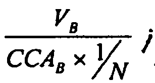
input device 11, the battery voltage (VB) of apresent battery 30 from the batterypower status unit 22, and a detection requirement including a 1/N CCA inputted from the input device 11 (S10); - (b) calculating an equation of loading resistance with the battery capacity, the initial voltage and the detection requirements to obtain a proper loading resistance for the present battery 30 (S11), wherein the equation is
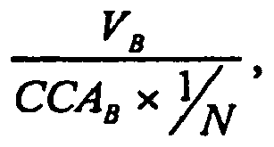
variable loading unit 21 in accordance with the calculated loading resistance; and - (c) executing a detecting process to obtain a detecting waveform (S12).
- With reference to
Fig. 4 , thevariable loading unit 21 has avariable resistor 21 a and aswitch 211. Thevariable resistor 21 a is electronically connected to the detectingwires 12. Thevariable resistor 21a is electronically connected to themicroprocessor 20. Theswitch 211 is electronically connected between one of the detectingwire 12 and the corresponding end of thevariable resistor 21a. Themicroprocessor 20 adjusts resistance of thevariable resistor 21a. Themicroprocessor 20 further controls theswitch 211 to be turned on or off. - For example, if the user detects the health of the
present battery 30 with 12 V/1000 CCA, the user may select 1/2 CCA to detect thebattery 30 by theinput device 11. Therefore, themicroprocessor 20 of the battery tester obtains detection requirements: CCAB=1000 CCA, VB=12V, 1/N CCA=1/2 CCA, so a proper loading resistance is calculated by the equation of loading resistance and the resistance will be 0.024 ohm. Themicroprocessor 20 controls thevariable resistor 21a to adjust the resistance of thevariable resistor 21a to be 0.024 ohm. When the detectingwires 12 arecused to clip to theelectrodes 31 of thebattery 30, thevariable resistor 21a with 0.024 ohm is added to thebattery 30. - In another example, if the user detects the health of the
present battery 30 with 12 V/900 CCA, the user may select 1/3 CCA to detect thebattery 30 by theinput device 11. Therefore, themicroprocessor 20 of the battery tester obtains detection requirements: CCAB=900 CCA, VB=12V, 1/N CCA=1/3 CCA, so a proper loading resistance is calculated by the equation of loading resistance and the resistance will be 0.04 ohm. Themicroprocessor 20 controls thevariable resistor 21a to adjust the resistance of the variable resistor to be 0.04 ohm. When the detectingwires 12 clip to the electrodes of thebattery 30, the variable resistor with 0.04 ohm is added to thebattery 30. - Based on the above two examples, the resistance of the variable resistor can be changed according to the different capacities of the batteries.
- With further reference to
Fig. 5A , another embodiment of thevariable loading unit 21 hasmultiple resistors 21b and switchingelements 21c. First ends of theresistors 21b are electronically connected to the detectingwires 12 and second ends of theresistors 21 b are respectively and electronically connected to the other detectingwire 12 through thecorresponding switching elements 21c. The switchingelements 21 c are electronically connected to themicroprocessor 20. Themicroprocessor 20 drives each switchingelement 21c to be turned on or turned off to determine which oneresistor 21b is connected to the twoelectrodes 31 of thebattery 30, or whichresistors 21b are electronically and parallelly connected to the twoelectrodes 31 of thebattery 30. When a proper loading resistance is determined by themicroprocessor 20, themicroprocessor 20 drives one ormore switching elements 21 c to be turned on according to the loading resistance. If two ormore switching elements 21c are driven to be turned on at the same time, the resistance of the variable loading unit is smaller than that of one of theresistors 21b. - With reference to
Fig. 5C , another embodiment of the variable loading unit has a programmablevariable resistor 21e and aswitch 211. The programmablevariable resistor 21e is electronically connected to the detectingwires 12. A controlling end of theprogram variable resistor 21e is connected to themicroprocessor 20. Themicroprocessor 20 directly adjusts the resistance of the programmablevariable resistor 21e and drives theswitch 211 to be turned on or off to determine whether the programmablevariable resistor 21e is connected to thebattery 30 or not. In addition, themicroprocessor 20 is connected to the controlling end of the programmablevariable resistor 21 e through abuffer 21f. - For example, if the
resistors 21b have the same resistance as inFig. 5A , and the resistance is 0.08ohm, one battery with 12V/750CCA is detected by the battery tester as shown inFig. 5A . The user uses theinput device 11 to select the 1/2CCA and 15sec loading time to enter the testing process. - Since the
resistors 21b have the same resistance, the loading of the battery is 0.08ohm when themicroprocessor 20 drives one of theswitches 21c to be turned on. Themicroprocessor 20 has a powerstatus detecting unit 22 to detect a present current value of thebattery 30 with 0.08ohm. When the current value is equal to 100A, themicroprocessor 20 calculates a proper loading resistance and the calculating process has the following steps of: - (a) calculating the numbers of the resistors with 0.08ohm; wherein [750*(1/2)/]/100=3.75; and
- (b) calculating a total detecting power by 1/2 CCA and 15 sec, wherein the total detecting power is [750*(1/2)]* 15=5625(A-sec).
- Since the
microprocessor 20 just selects 3resistors 21b to parallelly connect to thebattery 30, the initial detection requirements input by the user are changed. A new loading time is changed to 18.75sec as calculated by an equation: 5625/300=18.75 sec. - In this example, the
microprocessor 20 turns on 3switches 21c, and the 3resistors 21b are electronically and parallelly connected to thebattery 30 for 18.75 sec. - With further reference to
Fig. 5B , another embodiment of the variable loading unit hasmultiple resistors 21 b connected in serial and a 1 toX multiplexer 21d having one common terminal COM and X switching terminals S1 to Sx. X is the number of theresistors 21b. One end A of the series of the resistors is connected to one detectingwire 12 and the other detectingwire 12 is connected to the common terminal COM of themultiplexer 21 d. The switching terminals S1 to Sx of themultiplexer 21 d are respectively connected to serial nodes of the series of theresistors 21b and the other end B of the series of theresistors 21b. Themicroprocessor 20 drives the common terminal COM to connect to one of the switching terminals S1 to Sx to determine a resistance of the variable loading unit. - For example, the
resistors 21b have the same resistance (0.08ohm) and a battery with 12V/1000CCA is detected. The user selects 1/2 CCA and 15sec loading time to detect the health of thebattery 30. - Since the variable loading unit has
multiple resistors 21b, oneresistor 21b is first connected to thebattery 30 by driving themultiplexer 21d and detects whether a present current value achieves 12/0.08=150A. If the current value achieves 150A, themicroprocessor 20 further calculates a proper loading for thepresent battery 30. The calculating process has the following steps of: - (a)

- (b)

- When the
microprocessor 20 executes the loading process, themicroprocessor 20drives multiplexer 21d and the common terminal COM is connected to a first switching terminal S1. Oneresistor 21b is selected to connect to thebattery 30 through the detectingwires 12. In addition, the initial loading time (15sec) is changed to 50sec as a new loading time. - For another example, to detect another
battery 30 with 12V/100CCA, themicroprocessor 20 drives themultiplexer 21d and selects 3resistors 21 b to connect to thebattery 30 to detect the present current value (12V/0.24=50A). According to the present current value, themicroprocessor 20 calculates a proper loading resistance. The calculating method has the following steps of: - (a)

- (b)

- When the
microprocessor 20 executes the loading process, themicroprocessor 20 drives multiplexer 21 d, and the common terminal COM is connected to a third switching terminal S3. The series of the threeresistors 21b is selected to connect to thebattery 30 through the detectingwires 12 to detect aging of thebattery 30. - Based on the foregoing description, the
variable loading unit 21 hasmultiple resistors 21b but themicroprocessor 20 executes the strategic decision process to adjust the numbers of theresistors 21b and changes the initial loading time selected by the user. Therefore, themicroprocessor 20 still obtains accuracy, detecting for thebattery 30 with different capacities. - With reference to
Figs. 1 ,7 and8 , the detecting waveform obtained by themicroprocessor 20 and the flow chart of the detecting process are shown. In detecting process, thebattery 30 is first charged to full capacity and just removed from a charger. Thevariable loading unit 21 is then connected to thebattery 30. Themicroprocessor 20 detects a discharging power of thebattery 30 through thevariable loading unit 21 and monitors whether a discharging power of thebattery 30 achieves a present power vale (Ve2). When the discharging power achieves the present power value, the switches 21C are removed from the battery so thevariable loading unit 21 is disconnected from the battery (S40). Therefore, thebattery 30 has no surface charge voltage. Then, thevariable loading unit 21 is alternatively connected to thebattery 30 to detect multiple voltage values and current values of the battery 30 (S41). Finally, the detecting waveform is completed by the voltage values and/or current values and the microprocessor determines the health of the battery according to the detecting waveform (S42). - Even though numerous characteristics and advantages of the present invention have been set forth in the foregoing description, together with details of the structure and function of the invention, the disclosure is illustrative only. Changes may be made in detail, especially in matters of shape, size, and arrangement of parts within the principles of the invention to the full extent indicated by the broad general meaning of the terms in which the appended claims are expressed.
Claims (8)
- A battery tester, comprising a casing (10) having an input device (11) and two detecting wires (12), a microprocessor (20), a variable loading unit (21) and a battery power status detecting unit (22), wherein:the detecting wires (12) are adapted to selectively connect to two electrodes (31) of a battery (30);the variable loading unit (21) is electronically connected to the microprocessor (20) and connected to the detecting wires (12); andthe battery power status detecting unit (22) is electronically connected to the microprocessor (20) to detect a battery voltage (VB) and a battery current (IB) of the battery (30) and to report the battery voltage (VB) and battery current (IB) to the microprocessor (20); characterized in:the input device (11) providing different options of cold cranking amperes (CCAB) and detection requirements including a 1/N CCA; andthe microprocessor (20) storing a strategic decision process and being adapted to execute the following steps of this process:(a) obtaining an initial battery voltage (VB) of a present battery (30) and reading the cold cranking amperes (CCAB) and the 1/N CCA from the input device 11 (S 10);(b) calculating an equation of loading resistance with the cold cranking amperes (CCAB), the initial battery voltage (VB) and the 1/N CCA to obtain a proper loading resistance for the battery (30), and adjusting a resistance of the variable loading unit (21) in accordance with the calculated loading resistance (S11); wherein the equation is:
 (c) executing a detecting process to obtain a detecting waveform (S12).
 - The battery tester as claimed in claim 1, wherein the variable loading unit (21) is a variable resistor (21a) having:two ends respectively connected to the detecting wires (12); andone controlling end electronically connected to the microprocessor 20, wherein the microprocessor (20) is adapted to adjust the resistance of the variable resistor (21a).
- The battery tester as claimed in claim 1, wherein the variable loading unit (21) has multiple resistors (21b) and multiple switches (21c) electronically connected to the microprocessor (20), wherein one end of each resistor (21 b) is connected to one of the detecting wires (12), and the other ends of the resistors (21 b) are respectively connected to the other detecting wire (12) through the switches (2 1 c).
- The battery tester as claimed in claim 1, wherein the variable loading unit (21) has:multiple resistors (21b) connected in serial to be a series of the resistors, wherein one end of the series of the resistors (21 b) is connected to one of the detecting wires (12); anda multiplexer (21d) having:a common terminal connected to the other detecting wire (12);multiple switching terminals respectively connected to serial nodes of the series of the resistors (21b) and the other end of the series of the resistors (21b); anda controlling terminal electronically connected to the microprocessor (20), wherein the microprocessor (20) is adapted to drive the multiplexer (21d) to determine which one of the switching terminals is connected to the common terminal.
- The battery tester as claimed in claim 1, wherein the variable loading unit (21) has:a programmable variable resistor (21e) having a controlling end electronically connected to the microprocessor (20); anda switch (211) connected between the programmable variable resistor (21e) and the detecting wire (12), and electronically connected to the microprocessor (20).
- The battery tester as claimed in claim 1, wherein the variable loading unit has:a programmable variable resistor (21e) having:two ends respectively connected to the detecting wires (12); anda controlling end electronically connected to the microprocessor (20);a buffer 21f electronically connected between the microprocessor (20) and controlling end of the programmable variable resistor (21e); anda switch (211) connected between one end of the programmable variable resistor (21e), and the detecting wire (12) and electronically connected to the microprocessor (20).
- The battery tester as claimed in claim 1, wherein the detecting process has steps of:(a) charging the battery to full capacity and then just removed from a charger (S40);(b) connecting the variable loading (21) unit to discharge the battery (30) and monitoring the discharging power status (S40);(c) disconnecting the variable loading unit (21) from the battery (30) until the battery (30) discharges to a power threshold_(S40);(d) alternatively connecting the variable loading unit (21) to the battery (30) to detect multiple voltage values and current values of the battery (30) (S41); and(e) completing the detecting waveform by the voltage values and current values (S42).
- The battery tester as claimed in claim 1, wherein the casing further comprises a display (13), a computer connector (14) and an alarm (15).
Priority Applications (2)
| Application Number | Priority Date | Filing Date | Title |
|---|---|---|---|
| EP11002742.2A EP2506024B1 (en) | 2011-04-01 | 2011-04-01 | Battery tester for cold cranking amperes test |
| ES11002742T ES2431087T3 (en) | 2011-04-01 | 2011-04-01 | Battery tester for cold start amperage test |
Applications Claiming Priority (1)
| Application Number | Priority Date | Filing Date | Title |
|---|---|---|---|
| EP11002742.2A EP2506024B1 (en) | 2011-04-01 | 2011-04-01 | Battery tester for cold cranking amperes test |
Publications (2)
| Publication Number | Publication Date |
|---|---|
| EP2506024A1 EP2506024A1 (en) | 2012-10-03 |
| EP2506024B1 true EP2506024B1 (en) | 2013-08-21 |
Family
ID=44117064
Family Applications (1)
| Application Number | Title | Priority Date | Filing Date |
|---|---|---|---|
| EP11002742.2A Active EP2506024B1 (en) | 2011-04-01 | 2011-04-01 | Battery tester for cold cranking amperes test |
Country Status (2)
| Country | Link |
|---|---|
| EP (1) | EP2506024B1 (en) |
| ES (1) | ES2431087T3 (en) |
Families Citing this family (5)
| Publication number | Priority date | Publication date | Assignee | Title |
|---|---|---|---|---|
| JP6262008B2 (en) * | 2014-02-14 | 2018-01-17 | 株式会社富士通テレコムネットワークス福島 | Contact resistance measurement system |
| FR3076907B1 (en) * | 2018-01-17 | 2020-01-31 | E-Xteq Europe | APPARATUS FOR TESTING A BATTERY |
| TWI737253B (en) * | 2020-04-07 | 2021-08-21 | 昶懋國際股份有限公司 | Battery connector conversion device |
| US11796604B2 (en) | 2020-07-14 | 2023-10-24 | Hioki E.E. Corporation | Measuring apparatus and testing apparatus |
| FR3134895B1 (en) * | 2022-04-21 | 2024-03-22 | Be Energy | Diagnostic method for determining the suitability of a lead-acid battery for regeneration |
Family Cites Families (6)
| Publication number | Priority date | Publication date | Assignee | Title |
|---|---|---|---|---|
| US4707795A (en) * | 1983-03-14 | 1987-11-17 | Alber Engineering, Inc. | Battery testing and monitoring system |
| US5773977A (en) * | 1996-04-18 | 1998-06-30 | Johnson Controls Technology Company | Method of testing an electric storage battery by determining a bounce-back voltage after a load has been removed |
| EP1032955A4 (en) * | 1998-07-27 | 2002-08-07 | Gnb Technologies | DEVICE AND METHOD FOR PERFORMING DIAGNOSTIC TESTS ON BATTERIES AND FOR FAST CHARGING BATTERIES |
| US6369577B1 (en) * | 2001-03-02 | 2002-04-09 | Dhc Specialty Corp. | Electronic battery tester |
| US20060244423A1 (en) * | 2005-04-28 | 2006-11-02 | Auto Meter Products, Inc. | Heavy duty battery system testor and method |
| US9304170B2 (en) * | 2008-03-24 | 2016-04-05 | Bosch Automotive Service Solutions Inc. | Modular heavy load battery test system |
-
2011
- 2011-04-01 EP EP11002742.2A patent/EP2506024B1/en active Active
- 2011-04-01 ES ES11002742T patent/ES2431087T3/en active Active
Also Published As
| Publication number | Publication date |
|---|---|
| ES2431087T3 (en) | 2013-11-25 |
| EP2506024A1 (en) | 2012-10-03 |
Similar Documents
| Publication | Publication Date | Title |
|---|---|---|
| US11688891B2 (en) | Battery charger with battery state detection | |
| US8788226B2 (en) | Battery tester with high precision | |
| EP1619512B1 (en) | Device and method for the determination of the internal resistance of a batterie | |
| CN103149535B (en) | Method and apparatus for online determination of battery state of charge and state of health | |
| US9841465B2 (en) | Battery DC impedance measurement | |
| EP2703829B1 (en) | Device and method for estimating the degradation of battery capacity | |
| US6707303B2 (en) | Electronic battery tester | |
| CN109073712B (en) | Battery status detection system and method | |
| US20040002836A1 (en) | Apparatus and method for testing and charging a power source with ethernet | |
| EP3214456A1 (en) | Secondary battery state detection device and secondary battery state detection method | |
| EP2506024B1 (en) | Battery tester for cold cranking amperes test | |
| EP2808689A2 (en) | Monitoring battery contact point in charge/discharge system with batteries connected in series | |
| US20120245871A1 (en) | Battery tester with high precision | |
| CN102466781B (en) | High-accuracy storage battery detection device | |
| US9335382B2 (en) | Battery tester with high precision | |
| JP5608935B2 (en) | High precision tester | |
| EP2506023B1 (en) | Battery tester for cold cranking amperes test | |
| TWI547703B (en) | State of charge determination systems and methods | |
| JP5515181B2 (en) | Battery tester | |
| CN116973787A (en) | Method and device for determining the impedance of a rechargeable electric energy store |
Legal Events
| Date | Code | Title | Description |
|---|---|---|---|
| PUAI | Public reference made under article 153(3) epc to a published international application that has entered the european phase |
Free format text: ORIGINAL CODE: 0009012 |
|
| AK | Designated contracting states |
Kind code of ref document: A1 Designated state(s): AL AT BE BG CH CY CZ DE DK EE ES FI FR GB GR HR HU IE IS IT LI LT LU LV MC MK MT NL NO PL PT RO RS SE SI SK SM TR |
|
| AX | Request for extension of the european patent |
Extension state: BA ME |
|
| 17P | Request for examination filed |
Effective date: 20121115 |
|
| GRAP | Despatch of communication of intention to grant a patent |
Free format text: ORIGINAL CODE: EPIDOSNIGR1 |
|
| INTG | Intention to grant announced |
Effective date: 20130415 |
|
| GRAS | Grant fee paid |
Free format text: ORIGINAL CODE: EPIDOSNIGR3 |
|
| GRAA | (expected) grant |
Free format text: ORIGINAL CODE: 0009210 |
|
| AK | Designated contracting states |
Kind code of ref document: B1 Designated state(s): AL AT BE BG CH CY CZ DE DK EE ES FI FR GB GR HR HU IE IS IT LI LT LU LV MC MK MT NL NO PL PT RO RS SE SI SK SM TR |
|
| REG | Reference to a national code |
Ref country code: GB Ref legal event code: FG4D |
|
| REG | Reference to a national code |
Ref country code: CH Ref legal event code: EP |
|
| REG | Reference to a national code |
Ref country code: AT Ref legal event code: REF Ref document number: 628394 Country of ref document: AT Kind code of ref document: T Effective date: 20130915 |
|
| REG | Reference to a national code |
Ref country code: IE Ref legal event code: FG4D |
|
| REG | Reference to a national code |
Ref country code: DE Ref legal event code: R096 Ref document number: 602011002628 Country of ref document: DE Effective date: 20131024 |
|
| REG | Reference to a national code |
Ref country code: ES Ref legal event code: FG2A Ref document number: 2431087 Country of ref document: ES Kind code of ref document: T3 Effective date: 20131125 |
|
| REG | Reference to a national code |
Ref country code: NL Ref legal event code: T3 |
|
| REG | Reference to a national code |
Ref country code: AT Ref legal event code: MK05 Ref document number: 628394 Country of ref document: AT Kind code of ref document: T Effective date: 20130821 |
|
| REG | Reference to a national code |
Ref country code: LT Ref legal event code: MG4D |
|
| PG25 | Lapsed in a contracting state [announced via postgrant information from national office to epo] |
Ref country code: HR Free format text: LAPSE BECAUSE OF FAILURE TO SUBMIT A TRANSLATION OF THE DESCRIPTION OR TO PAY THE FEE WITHIN THE PRESCRIBED TIME-LIMIT Effective date: 20130821 Ref country code: NO Free format text: LAPSE BECAUSE OF FAILURE TO SUBMIT A TRANSLATION OF THE DESCRIPTION OR TO PAY THE FEE WITHIN THE PRESCRIBED TIME-LIMIT Effective date: 20131121 Ref country code: AT Free format text: LAPSE BECAUSE OF FAILURE TO SUBMIT A TRANSLATION OF THE DESCRIPTION OR TO PAY THE FEE WITHIN THE PRESCRIBED TIME-LIMIT Effective date: 20130821 Ref country code: SE Free format text: LAPSE BECAUSE OF FAILURE TO SUBMIT A TRANSLATION OF THE DESCRIPTION OR TO PAY THE FEE WITHIN THE PRESCRIBED TIME-LIMIT Effective date: 20130821 Ref country code: LT Free format text: LAPSE BECAUSE OF FAILURE TO SUBMIT A TRANSLATION OF THE DESCRIPTION OR TO PAY THE FEE WITHIN THE PRESCRIBED TIME-LIMIT Effective date: 20130821 Ref country code: IS Free format text: LAPSE BECAUSE OF FAILURE TO SUBMIT A TRANSLATION OF THE DESCRIPTION OR TO PAY THE FEE WITHIN THE PRESCRIBED TIME-LIMIT Effective date: 20131221 Ref country code: PT Free format text: LAPSE BECAUSE OF FAILURE TO SUBMIT A TRANSLATION OF THE DESCRIPTION OR TO PAY THE FEE WITHIN THE PRESCRIBED TIME-LIMIT Effective date: 20131223 Ref country code: CY Free format text: LAPSE BECAUSE OF FAILURE TO SUBMIT A TRANSLATION OF THE DESCRIPTION OR TO PAY THE FEE WITHIN THE PRESCRIBED TIME-LIMIT Effective date: 20130911 |
|
| PG25 | Lapsed in a contracting state [announced via postgrant information from national office to epo] |
Ref country code: LV Free format text: LAPSE BECAUSE OF FAILURE TO SUBMIT A TRANSLATION OF THE DESCRIPTION OR TO PAY THE FEE WITHIN THE PRESCRIBED TIME-LIMIT Effective date: 20130821 Ref country code: SI Free format text: LAPSE BECAUSE OF FAILURE TO SUBMIT A TRANSLATION OF THE DESCRIPTION OR TO PAY THE FEE WITHIN THE PRESCRIBED TIME-LIMIT Effective date: 20130821 Ref country code: GR Free format text: LAPSE BECAUSE OF FAILURE TO SUBMIT A TRANSLATION OF THE DESCRIPTION OR TO PAY THE FEE WITHIN THE PRESCRIBED TIME-LIMIT Effective date: 20131122 Ref country code: FI Free format text: LAPSE BECAUSE OF FAILURE TO SUBMIT A TRANSLATION OF THE DESCRIPTION OR TO PAY THE FEE WITHIN THE PRESCRIBED TIME-LIMIT Effective date: 20130821 Ref country code: BE Free format text: LAPSE BECAUSE OF FAILURE TO SUBMIT A TRANSLATION OF THE DESCRIPTION OR TO PAY THE FEE WITHIN THE PRESCRIBED TIME-LIMIT Effective date: 20130821 Ref country code: PL Free format text: LAPSE BECAUSE OF FAILURE TO SUBMIT A TRANSLATION OF THE DESCRIPTION OR TO PAY THE FEE WITHIN THE PRESCRIBED TIME-LIMIT Effective date: 20130821 |
|
| PG25 | Lapsed in a contracting state [announced via postgrant information from national office to epo] |
Ref country code: CY Free format text: LAPSE BECAUSE OF FAILURE TO SUBMIT A TRANSLATION OF THE DESCRIPTION OR TO PAY THE FEE WITHIN THE PRESCRIBED TIME-LIMIT Effective date: 20130821 |
|
| PG25 | Lapsed in a contracting state [announced via postgrant information from national office to epo] |
Ref country code: SK Free format text: LAPSE BECAUSE OF FAILURE TO SUBMIT A TRANSLATION OF THE DESCRIPTION OR TO PAY THE FEE WITHIN THE PRESCRIBED TIME-LIMIT Effective date: 20130821 Ref country code: RO Free format text: LAPSE BECAUSE OF FAILURE TO SUBMIT A TRANSLATION OF THE DESCRIPTION OR TO PAY THE FEE WITHIN THE PRESCRIBED TIME-LIMIT Effective date: 20130821 Ref country code: CZ Free format text: LAPSE BECAUSE OF FAILURE TO SUBMIT A TRANSLATION OF THE DESCRIPTION OR TO PAY THE FEE WITHIN THE PRESCRIBED TIME-LIMIT Effective date: 20130821 Ref country code: DK Free format text: LAPSE BECAUSE OF FAILURE TO SUBMIT A TRANSLATION OF THE DESCRIPTION OR TO PAY THE FEE WITHIN THE PRESCRIBED TIME-LIMIT Effective date: 20130821 Ref country code: EE Free format text: LAPSE BECAUSE OF FAILURE TO SUBMIT A TRANSLATION OF THE DESCRIPTION OR TO PAY THE FEE WITHIN THE PRESCRIBED TIME-LIMIT Effective date: 20130821 |
|
| PLBE | No opposition filed within time limit |
Free format text: ORIGINAL CODE: 0009261 |
|
| STAA | Information on the status of an ep patent application or granted ep patent |
Free format text: STATUS: NO OPPOSITION FILED WITHIN TIME LIMIT |
|
| 26N | No opposition filed |
Effective date: 20140522 |
|
| REG | Reference to a national code |
Ref country code: DE Ref legal event code: R097 Ref document number: 602011002628 Country of ref document: DE Effective date: 20140522 |
|
| PG25 | Lapsed in a contracting state [announced via postgrant information from national office to epo] |
Ref country code: LU Free format text: LAPSE BECAUSE OF FAILURE TO SUBMIT A TRANSLATION OF THE DESCRIPTION OR TO PAY THE FEE WITHIN THE PRESCRIBED TIME-LIMIT Effective date: 20140401 Ref country code: MC Free format text: LAPSE BECAUSE OF FAILURE TO SUBMIT A TRANSLATION OF THE DESCRIPTION OR TO PAY THE FEE WITHIN THE PRESCRIBED TIME-LIMIT Effective date: 20130821 |
|
| REG | Reference to a national code |
Ref country code: CH Ref legal event code: PL |
|
| REG | Reference to a national code |
Ref country code: IE Ref legal event code: MM4A |
|
| PG25 | Lapsed in a contracting state [announced via postgrant information from national office to epo] |
Ref country code: CH Free format text: LAPSE BECAUSE OF NON-PAYMENT OF DUE FEES Effective date: 20140430 Ref country code: LI Free format text: LAPSE BECAUSE OF NON-PAYMENT OF DUE FEES Effective date: 20140430 |
|
| PG25 | Lapsed in a contracting state [announced via postgrant information from national office to epo] |
Ref country code: IE Free format text: LAPSE BECAUSE OF NON-PAYMENT OF DUE FEES Effective date: 20140401 |
|
| REG | Reference to a national code |
Ref country code: FR Ref legal event code: PLFP Year of fee payment: 6 |
|
| PG25 | Lapsed in a contracting state [announced via postgrant information from national office to epo] |
Ref country code: MT Free format text: LAPSE BECAUSE OF FAILURE TO SUBMIT A TRANSLATION OF THE DESCRIPTION OR TO PAY THE FEE WITHIN THE PRESCRIBED TIME-LIMIT Effective date: 20130821 |
|
| PG25 | Lapsed in a contracting state [announced via postgrant information from national office to epo] |
Ref country code: SM Free format text: LAPSE BECAUSE OF FAILURE TO SUBMIT A TRANSLATION OF THE DESCRIPTION OR TO PAY THE FEE WITHIN THE PRESCRIBED TIME-LIMIT Effective date: 20130821 |
|
| PG25 | Lapsed in a contracting state [announced via postgrant information from national office to epo] |
Ref country code: RS Free format text: LAPSE BECAUSE OF FAILURE TO SUBMIT A TRANSLATION OF THE DESCRIPTION OR TO PAY THE FEE WITHIN THE PRESCRIBED TIME-LIMIT Effective date: 20130821 Ref country code: BG Free format text: LAPSE BECAUSE OF FAILURE TO SUBMIT A TRANSLATION OF THE DESCRIPTION OR TO PAY THE FEE WITHIN THE PRESCRIBED TIME-LIMIT Effective date: 20130821 |
|
| PG25 | Lapsed in a contracting state [announced via postgrant information from national office to epo] |
Ref country code: TR Free format text: LAPSE BECAUSE OF FAILURE TO SUBMIT A TRANSLATION OF THE DESCRIPTION OR TO PAY THE FEE WITHIN THE PRESCRIBED TIME-LIMIT Effective date: 20130821 Ref country code: HU Free format text: LAPSE BECAUSE OF FAILURE TO SUBMIT A TRANSLATION OF THE DESCRIPTION OR TO PAY THE FEE WITHIN THE PRESCRIBED TIME-LIMIT; INVALID AB INITIO Effective date: 20110401 |
|
| REG | Reference to a national code |
Ref country code: FR Ref legal event code: PLFP Year of fee payment: 7 |
|
| PGFP | Annual fee paid to national office [announced via postgrant information from national office to epo] |
Ref country code: NL Payment date: 20170426 Year of fee payment: 7 |
|
| PGFP | Annual fee paid to national office [announced via postgrant information from national office to epo] |
Ref country code: ES Payment date: 20170517 Year of fee payment: 7 |
|
| REG | Reference to a national code |
Ref country code: FR Ref legal event code: PLFP Year of fee payment: 8 |
|
| PGFP | Annual fee paid to national office [announced via postgrant information from national office to epo] |
Ref country code: GB Payment date: 20180301 Year of fee payment: 8 |
|
| PGFP | Annual fee paid to national office [announced via postgrant information from national office to epo] |
Ref country code: IT Payment date: 20180302 Year of fee payment: 8 |
|
| PG25 | Lapsed in a contracting state [announced via postgrant information from national office to epo] |
Ref country code: MK Free format text: LAPSE BECAUSE OF FAILURE TO SUBMIT A TRANSLATION OF THE DESCRIPTION OR TO PAY THE FEE WITHIN THE PRESCRIBED TIME-LIMIT Effective date: 20130821 |
|
| PG25 | Lapsed in a contracting state [announced via postgrant information from national office to epo] |
Ref country code: AL Free format text: LAPSE BECAUSE OF FAILURE TO SUBMIT A TRANSLATION OF THE DESCRIPTION OR TO PAY THE FEE WITHIN THE PRESCRIBED TIME-LIMIT Effective date: 20130821 |
|
| REG | Reference to a national code |
Ref country code: NL Ref legal event code: MM Effective date: 20180501 |
|
| PG25 | Lapsed in a contracting state [announced via postgrant information from national office to epo] |
Ref country code: NL Free format text: LAPSE BECAUSE OF NON-PAYMENT OF DUE FEES Effective date: 20180501 |
|
| REG | Reference to a national code |
Ref country code: ES Ref legal event code: FD2A Effective date: 20190911 |
|
| PG25 | Lapsed in a contracting state [announced via postgrant information from national office to epo] |
Ref country code: ES Free format text: LAPSE BECAUSE OF NON-PAYMENT OF DUE FEES Effective date: 20180402 |
|
| GBPC | Gb: european patent ceased through non-payment of renewal fee |
Effective date: 20190401 |
|
| PG25 | Lapsed in a contracting state [announced via postgrant information from national office to epo] |
Ref country code: GB Free format text: LAPSE BECAUSE OF NON-PAYMENT OF DUE FEES Effective date: 20190401 |
|
| PG25 | Lapsed in a contracting state [announced via postgrant information from national office to epo] |
Ref country code: IT Free format text: LAPSE BECAUSE OF NON-PAYMENT OF DUE FEES Effective date: 20190401 |
|
| PGFP | Annual fee paid to national office [announced via postgrant information from national office to epo] |
Ref country code: FR Payment date: 20250123 Year of fee payment: 15 |
|
| PGFP | Annual fee paid to national office [announced via postgrant information from national office to epo] |
Ref country code: DE Payment date: 20250205 Year of fee payment: 15 |