EP2492706A1 - An apparatus for determining whether a kinematic report emitted by a co-operative sensor is bearing-spoofed or not - Google Patents
An apparatus for determining whether a kinematic report emitted by a co-operative sensor is bearing-spoofed or not Download PDFInfo
- Publication number
- EP2492706A1 EP2492706A1 EP11155483A EP11155483A EP2492706A1 EP 2492706 A1 EP2492706 A1 EP 2492706A1 EP 11155483 A EP11155483 A EP 11155483A EP 11155483 A EP11155483 A EP 11155483A EP 2492706 A1 EP2492706 A1 EP 2492706A1
- Authority
- EP
- European Patent Office
- Prior art keywords
- bearing
- report
- antennae
- voltages
- received
- Prior art date
- Legal status (The legal status is an assumption and is not a legal conclusion. Google has not performed a legal analysis and makes no representation as to the accuracy of the status listed.)
- Withdrawn
Links
- 230000005855 radiation Effects 0.000 claims description 6
- 238000001514 detection method Methods 0.000 description 8
- 238000000034 method Methods 0.000 description 8
- 230000005540 biological transmission Effects 0.000 description 5
- 230000008901 benefit Effects 0.000 description 4
- 230000005404 monopole Effects 0.000 description 4
- 238000000926 separation method Methods 0.000 description 4
- 238000009795 derivation Methods 0.000 description 3
- 238000004364 calculation method Methods 0.000 description 2
- 230000000694 effects Effects 0.000 description 2
- 230000004927 fusion Effects 0.000 description 2
- 238000007499 fusion processing Methods 0.000 description 2
- 238000005305 interferometry Methods 0.000 description 2
- 238000010606 normalization Methods 0.000 description 2
- 230000003466 anti-cipated effect Effects 0.000 description 1
- 230000001419 dependent effect Effects 0.000 description 1
- 230000009349 indirect transmission Effects 0.000 description 1
- 230000010354 integration Effects 0.000 description 1
- 238000005259 measurement Methods 0.000 description 1
- 238000012544 monitoring process Methods 0.000 description 1
- 230000035755 proliferation Effects 0.000 description 1
- 238000006467 substitution reaction Methods 0.000 description 1
Images


Classifications
-
- G—PHYSICS
- G01—MEASURING; TESTING
- G01S—RADIO DIRECTION-FINDING; RADIO NAVIGATION; DETERMINING DISTANCE OR VELOCITY BY USE OF RADIO WAVES; LOCATING OR PRESENCE-DETECTING BY USE OF THE REFLECTION OR RERADIATION OF RADIO WAVES; ANALOGOUS ARRANGEMENTS USING OTHER WAVES
- G01S3/00—Direction-finders for determining the direction from which infrasonic, sonic, ultrasonic, or electromagnetic waves, or particle emission, not having a directional significance, are being received
- G01S3/02—Direction-finders for determining the direction from which infrasonic, sonic, ultrasonic, or electromagnetic waves, or particle emission, not having a directional significance, are being received using radio waves
- G01S3/14—Systems for determining direction or deviation from predetermined direction
- G01S3/28—Systems for determining direction or deviation from predetermined direction using amplitude comparison of signals derived simultaneously from receiving antennas or antenna systems having differently-oriented directivity characteristics
-
- H—ELECTRICITY
- H01—ELECTRIC ELEMENTS
- H01Q—ANTENNAS, i.e. RADIO AERIALS
- H01Q21/00—Antenna arrays or systems
- H01Q21/06—Arrays of individually energised antenna units similarly polarised and spaced apart
- H01Q21/20—Arrays of individually energised antenna units similarly polarised and spaced apart the units being spaced along or adjacent to a curvilinear path
- H01Q21/205—Arrays of individually energised antenna units similarly polarised and spaced apart the units being spaced along or adjacent to a curvilinear path providing an omnidirectional coverage
Definitions
- the present invention aims to provide an apparatus which do not require geographical separation between antennae, thus enabling operation in a restricted area such as a ship. It provides a solution to kinematic spoofing detection based on bearing spoofing detection.
- Bearing spoofing detection entails measuring the direction of arrival of a received AIS message and comparing this measured direction with the direction corresponding to the reported position, so as to determine unambiguous bearing and thus detect spoofing of the bearing value.
- the invention proposes an apparatus for determining whether a kinematic report emitted by a co-operative sensor is bearing-spoofed or not, the apparatus comprising means for receiving and processing the report.
- the apparatus comprises a directive antenna system having a 360-degrees bearing coverage and means for estimating the bearing from which the report has been received.
- the means for estimating the bearing from which the report has been received may include means for deducing the bearing from the ratio of power received by each of the antennae.
- the means for estimating the bearing from which the report has been received may include means for calculating the bearing corresponding to the position reported.
- the means for estimating the bearing from which the report has been received may comprise means for generating a spoofing notification if the bearing corresponding to the position reported deviates beyond a given threshold from the bearing deduced from the ratio of power received by each of the antennae.
- the ratio of the two strongest voltages may be deduced by normalizing said two strongest voltages, so as to compensate for differences in calibration among the two antennae providing said two strongest voltages.
- the report may be an AIS report.
- an advantage provided by the present invention is that it provides, unlike existing radio direction finders based on omni-directional antennae, a cheap solution for kinematic spoofing detection.
- it is based on existing transponders and its antenna system can be built at a low cost, by use of a simple loop and a monopole, both made of conductive wire.
- its tuning requires only passive components.
- the antennae 1, 2 and 3 may have a cardioid radiation pattern, governed by the expression (1+cos( ⁇ )) for example, where ⁇ designates the bearing varying from 0 to 360 degrees.
- the invention is, however, not limited by the use of cardioids patterns, nor by the number of antennae.
- the voltages provided as output of the three antennae 1, 2 and 3 are advantageously used to determine the Direction of Arrival of AIS messages (DoA m ) as well as to determine the Time of Arrival of AIS messages (ToA m ), where the subscript 'm' refers to 'measured'.
- spoofing detection is performed by first calculating the Direction Of Arrival corresponding to the position report (DOA r ), where the subscript 'r' refers to 'reported'. Such calculation is well-known from the prior art. If DOA m deviates significantly from DOA r , then a bearing-spoofing notification may be generated and send to the command and control system. Only spoofing-free AIS reports are indicated as genuine and are passed to further processing in the system, usually the fusion process.
- the exemplary embodiment of Figure 1 comprises an AIS receiver 4, which is connected to a monopole antenna 5 with omnidirectional radiation pattern, as sketched in the figure 1 . It is worth noting that any existing commercial AIS receiver is suitable. It is also worth noting that, as all existing AIS systems, the AIS receiver 4 and its monopole antenna 5 do not enable bearing measurement.
- a system separate from the receiver 4 may be used for the estimation of the bearings from which the AIS messages have been transmitted.
- Said system comprises the previously described directive antenna system 10 including the three 120-degrees cardioids antennae 1, 2 and 3, each coupled to a low noise amplifier (LNA) 6, 7 and 8, respectively. The LNAs 6, 7 and 8 bring the signals to baseband.
- LNA low noise amplifier
- the antenna 5 may be skipped by feeding the RF input of the AIS receiver 4 with the combined outputs of the LNAs 6, 7 and 8. However, this involves the use of an additional combiner module.
- Conditions for acceptable spoofing detection performance include sufficient accuracy in bearing estimation. Another condition is sufficient synchronization in the clocks of the senders and the receiver, which is achieved because they all use GPS as the source for their time. Yet another condition is absence of reception via indirect transmission paths, which is almost always true in a naval environment.
- the mathematical derivation of the bearing ⁇ is given for the unambiguous bearing angle of an emitter given the voltages v 1 , v 2 and v 3 provided as output of the three directional antennae 1, 2 and 3, respectively.
- the symmetry of the directional pattern among its maximum causes ambiguity.
- the angle can be at both sides of the maximum strength.
- a i is the normalized voltage from antenna i , whose value is between 0 and 1
- ⁇ i is the offset angle of the i th antenna.
- the values for ⁇ i are ( i -1) ⁇ 120 degrees.
- v 0 is the amplitude of the antenna signal before normalization.
- the first step includes determining which y belongs to which x .
- the result is two pairs ( x 1 , y 1 ) and ( x 2 , y 2 ).
- the second step includes determining for each of these pairs in which quadrant the solution is. This results in the correct angles ⁇ x and ⁇ y corresponding to the ambiguity that arises from the definition of the inverse sine and inverse cosine. While they both have a domain of [-1,1], the range of the former is [- ⁇ /2, ⁇ /2] and the range of the latter is [0, ⁇ ]. This is shown in Figure 3 .
- ⁇ x and ⁇ y for asin
- the corresponding real angle is ⁇ as shown in Figure 3 .
- the asin expression yields ⁇ ' and the acos expression yields ⁇ . Since ⁇ ' >0, we know that the real corresponding angle is within [0, ⁇ ].
- the third step includes using the angular segment determined by the strongest signals to select the right solution from ⁇ x and ⁇ y .
- the line referenced 11 represents the real bearing.
- ADS-B support may be provided by adding elevation estimation to the bearing estimation in order to get a 3D angular estimation.
- the antenna system however, becomes a lot more complex.
Landscapes
- Physics & Mathematics (AREA)
- Engineering & Computer Science (AREA)
- General Physics & Mathematics (AREA)
- Radar, Positioning & Navigation (AREA)
- Remote Sensing (AREA)
- Radar Systems Or Details Thereof (AREA)
Abstract
There is disclosed an apparatus for determining whether a kinematic report emitted by a co-operative sensor is bearing-spoofed or not.
The apparatus comprises means for receiving and processing the report.
The apparatus comprises a directive antenna system having a 360-degrees bearing coverage and means for estimating the bearing from which the report has been received.
Application : command and control systems
Description
- The present invention relates to an apparatus for determining whether a kinematic report emitted by a co-operative sensor is bearing-spoofed or not. For example, the invention is particularly applicable to command and control systems.
- The Automatic Identification System (AIS) is an automated system that enables localizing vessels by use of co-operative sensors. Co-operative sensors become more and more important in daily life and integration within navy systems is recommended for a number of reasons. A first reason is to benefit from the proliferation of AIS transponders on the large ships, over 300 tons, on which AIS is mandatory. However, it may also be anticipated that a lightweight version of AIS, which reports only the kinematics and which is easy to install, configure and operate, may proliferate on smaller ships as well in near future. A second reason is to benefit from the additional information that AIS messages convey.
- As long as operators of AIS transponders act sincerely, AIS messages can be trusted. However, AIS messages can be manipulated intentionally or unintentionally by the operator. When operators have bad intentions, they may tweak the messages they send out in order to mislead receiving parties about their position and heading (kinematic spoofing) and/or about their cargo and destination (non-kinematic spoofing).
- Although many message types have been defined for AIS, in this application we, explicitly or implicitly, assume the 'position report' message types, which deal with the kinematic properties.
- When a spoofed position report is fed into a surveillance system, it may disturb its operation and negatively impact the performance of the fusion and track management processes. Possible effects are track flapping and lost tracks, but the reason for this behaviour cannot be discovered. To avoid such behaviour caused by co-operative sensors, spoofed reports must be detected and prevented from entering the fusion process. Besides avoiding these negative effects, spoofed reports are valuable information in itself and occurrence of such should be reported to the command and control system.
- An often heard method for AIS spoofing detection is based on measuring the received power of an AIS message, and then estimating the range assuming this message has been sent at well-defined power levels. From the propagation losses the range can be estimated. This method relies on a calibrated receiver and adherence to the prescribed power levels. For unintentional spoofing detection this method may be useful. But the tough cases undoubtedly are the intentional spoofings, for which this method falls short. After all, an adversary able to spoof its position will certainly be able to manipulate the power level of its AIS transmissions!
- The patent application
US 2009/0322586 A1 discloses methods and apparatus for using interferometry to prevent spoofing of Automatic Dependent Surveillance-Broadcast (ADS-B) targets, ADS-B being a cooperative surveillance technique for air traffic control. A major drawback of the apparatus described in that application is that it comprises two or more omni-directional antennae with sufficient geographical separation for interferometry processes, which use exclusively time differences and triangulation to determine the position of emission. Such a geographical separation cannot be achieved onboard a ship and is a radical departure from the present invention, which requires only one physical location. Indeed, the fact that the operational domain for ADS-B is the airspace enables large range separation between antennae receiving an ADS-B report. - The present invention aims to provide an apparatus which do not require geographical separation between antennae, thus enabling operation in a restricted area such as a ship. It provides a solution to kinematic spoofing detection based on bearing spoofing detection. Bearing spoofing detection entails measuring the direction of arrival of a received AIS message and comparing this measured direction with the direction corresponding to the reported position, so as to determine unambiguous bearing and thus detect spoofing of the bearing value. At its most general, the invention proposes an apparatus for determining whether a kinematic report emitted by a co-operative sensor is bearing-spoofed or not, the apparatus comprising means for receiving and processing the report. The apparatus comprises a directive antenna system having a 360-degrees bearing coverage and means for estimating the bearing from which the report has been received.
- Advantageously, the directive antenna system may comprise a plurality of antennae arranged so as to provide the 360-degrees bearing coverage.
- Advantageously, the means for estimating the bearing from which the report has been received may include means for deducing the bearing from the ratio of power received by each of the antennae.
- Preferably, the means for estimating the bearing from which the report has been received may include means for calculating the bearing corresponding to the position reported.
- Preferably, the means for estimating the bearing from which the report has been received may comprise means for generating a spoofing notification if the bearing corresponding to the position reported deviates beyond a given threshold from the bearing deduced from the ratio of power received by each of the antennae.
- Preferably, the means for deducing the bearing may include means for deducing the ratio of the two strongest voltages among the voltages provided as output of each of the antennae.
- Preferably, the ratio of the two strongest voltages may be deduced by normalizing said two strongest voltages, so as to compensate for differences in calibration among the two antennae providing said two strongest voltages.
- For example, the report may be an AIS report.
- For example, the antennae may have a cardioid radiation pattern.
- It is important understanding that the bearing of receive is unambiguously coupled to the bearing of transmission within the propagation time of the report.
- Thus an advantage provided by the present invention is that it provides, unlike existing radio direction finders based on omni-directional antennae, a cheap solution for kinematic spoofing detection. In particular, it is based on existing transponders and its antenna system can be built at a low cost, by use of a simple loop and a monopole, both made of conductive wire. Moreover, its tuning requires only passive components.
- Non-limiting examples of the invention are described below with reference to the accompanying drawings in which :
-
figure 1 , schematically illustrates an exemplary embodiment of the present invention; -
figure 2 , graphically illustrates exemplary cardioids radiation patterns of three antennae which are suitable for embodying the present invention; -
figure 3 , graphically illustrates the resolution of ambiguity of bearing location with inverse sine and cosine according to the present invention; -
figure 4 , graphically illustrates the resolution of ambiguity of bearing location with respect to the principle axis of the antenna according to the present invention. - In the figures, like reference signs are assigned to like items.
- The present invention proposes using a constellation of three directional antennae within a same system node and utilizing the ratio of received powers at these antennae for determination of unambiguous bearing of a received AIS message. The estimated bearing is then compared with correspondingly reported information in the message. Afterwards, it is decided whether or not there is kinematic spoofing. In case of spoofing, access to fusion is denied to the spoofed report and a spoofing notification may be transmitted to a control and command system.
- The
Figure 1 illustrates an exemplary embodiment of the present invention. It may comprise adirective antenna system 10, which includes threeantennae Figure 1 . Theantennae antennae - As illustrated by
Figure 2 , theantennae - The voltages provided as output of the three
antennae - Then spoofing detection is performed by first calculating the Direction Of Arrival corresponding to the position report (DOAr), where the subscript 'r' refers to 'reported'. Such calculation is well-known from the prior art. If DOAm deviates significantly from DOAr, then a bearing-spoofing notification may be generated and send to the command and control system. Only spoofing-free AIS reports are indicated as genuine and are passed to further processing in the system, usually the fusion process.
- The exemplary embodiment of
Figure 1 comprises anAIS receiver 4, which is connected to amonopole antenna 5 with omnidirectional radiation pattern, as sketched in thefigure 1 . It is worth noting that any existing commercial AIS receiver is suitable. It is also worth noting that, as all existing AIS systems, theAIS receiver 4 and itsmonopole antenna 5 do not enable bearing measurement. Advantageously, a system separate from thereceiver 4 may be used for the estimation of the bearings from which the AIS messages have been transmitted. Said system comprises the previously describeddirective antenna system 10 including the three 120-degrees cardioids antennae LNAs bearing estimator 9, which successively performs several operations. An operation includes monitoring AIS transmissions and time-stamping them. This requires reference time, which may preferably be provided by a Global Positioning System (GPS). Another operation includes calculating the relative 'estimated bearing' of transmission by manipulating the strengths of signal at the threeantennae - In another embodiment, the
antenna 5 may be skipped by feeding the RF input of theAIS receiver 4 with the combined outputs of theLNAs - Conditions for acceptable spoofing detection performance include sufficient accuracy in bearing estimation. Another condition is sufficient synchronization in the clocks of the senders and the receiver, which is achieved because they all use GPS as the source for their time. Yet another condition is absence of reception via indirect transmission paths, which is almost always true in a naval environment.
- In the following, the mathematical derivation of the bearing ϕ is given for the unambiguous bearing angle of an emitter given the voltages v 1, v 2 and v 3 provided as output of the three
directional antennae - The following derivation shows that only two of the three voltages are sufficient to solve the ambiguity in the angle. Therefore the smallest voltage will not be taken into account in the calculation. Assume that v i and v j (i, j ∈ {1,2,3}) are the two strongest antenna voltages. It should be noted that only the ratio of the two strongest voltages can be used as the key information to determining the bearing of the emission. In this case the real bearing of emission is within the main axes of the corresponding antennas, i.e. known with a precision of the size of the angular segment of 120 degrees.
- The following normalization of the antenna signal is applied, so as to compensate for differences in calibration among the antennae:


where ai is the normalized voltage from antenna i, whose value is between 0 and 1, and ψi is the offset angle of the i th antenna. In the case of the present preferred embodiment, the values for ψi are (i-1)×120 degrees. v0 is the amplitude of the antenna signal before normalization. - Manipulating Equation (1) for antenna i and j and eliminating the sine term results in:


- Rewriting Equations (2) and (3) we get:


- Divide (4) by (5) and substitute cij for


- Equation (6) can be written as p.cosϕ+q.sinϕ+r=0. With the substitution sinϕ=(1-cos2ϕ)1/2 and some manipulation, a quadratic formula results:

- Where x = cosϕ. Equation (7) has two solutions, which can be found using the well-known abc-formula:
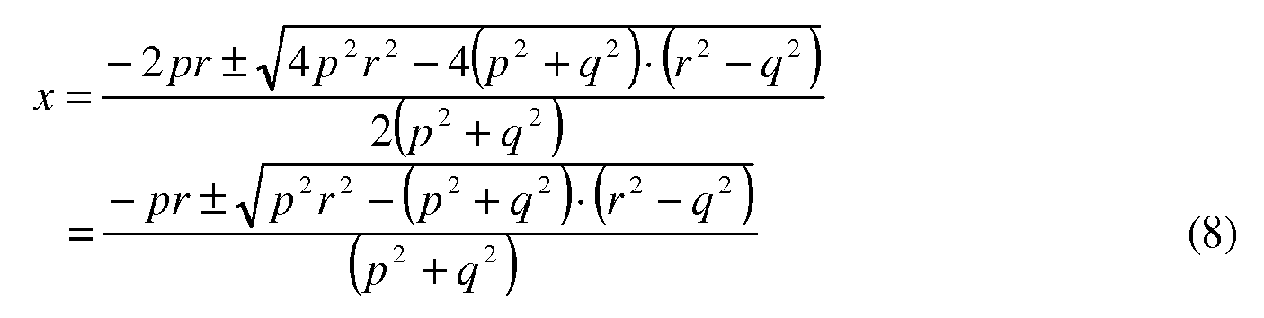


- A similar expression in sinϕ can be derived. This additional expression is derived from Equation (6) and reads:

where y =sinϕ. Equation (12) also has two solutions: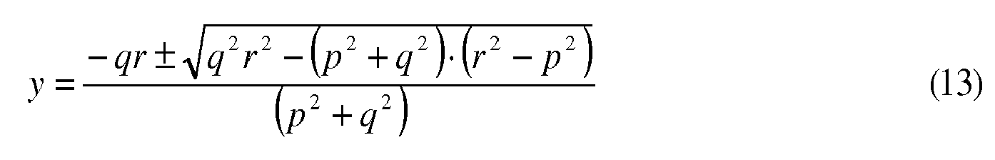
- We now have four solutions, and each of these four solutions has an ambiguity due to the fact that we have to take the inverse cosine (acos) or inverse sine (asin) of these solutions. There are three steps needed to remove the ambiguity of the solution.
- The first step includes determining which y belongs to which x. The result is two pairs (x 1,y 1) and (x 2,y 2).
- The second step includes determining for each of these pairs in which quadrant the solution is. This results in the correct angles ϕ x and ϕ y corresponding to the ambiguity that arises from the definition of the inverse sine and inverse cosine. While they both have a domain of [-1,1], the range of the former is [-π/2, π/2] and the range of the latter is [0,π]. This is shown in
Figure 3 . Suppose we have an argument x for acos and an argument y for asin, and the corresponding real angle is ϕ as shown inFigure 3 . The asin expression yields ϕ' and the acos expression yields ϕ. Since ϕ'>0, we know that the real corresponding angle is within [0,π]. Were ϕ'<0, then the real angle would be within [-π,0]. Likewise, because ϕ>π/2, the real value is within [π/2,3π/2]. Were ϕ<π/2, then the real angle would be within [-π/2, π/2]. Using these conditions, the correct angle can be found. - The third step includes using the angular segment determined by the strongest signals to select the right solution from ϕx and ϕy . In
Figure 4 , the line referenced 11 represents the real bearing. - It is worth noting that the present invention is applicable to other cooperative sensors as well. For example, ADS-B support may be provided by adding elevation estimation to the bearing estimation in order to get a 3D angular estimation. The antenna system, however, becomes a lot more complex.
Claims (9)
- An apparatus for determining whether a kinematic report emitted by a cooperative sensor is bearing-spoofed or not, the apparatus comprising means (4) for receiving and processing the report, the apparatus being characterized in that it comprises:- a directive antenna system (10) having a 360-degrees bearing coverage;- means (9) for estimating the bearing from which the report has been received.
- An apparatus according to Claim 1, characterized in that the directive antenna system (10) comprises a plurality of antennae (1, 2, 3) arranged so as to provide the 360-degrees bearing coverage.
- An apparatus according to Claim 2, characterized in that the means (9) for estimating the bearing from which the report has been received include means for deducing the bearing from the ratio of power received by each of the antennae (1, 2, 3).
- An apparatus according to Claim 3, characterized in that the means (9) for estimating the bearing from which the report has been received include means for calculating the bearing corresponding to the position reported.
- An apparatus according to Claim 4, characterized in that the means (9) for estimating the bearing from which the report has been received comprise means for generating a spoofing notification if the bearing corresponding to the position reported deviates beyond a given threshold from the bearing deduced from the ratio of power received by each of the antennae (1, 2, 3).
- An apparatus according to Claim 3, characterized in that the means for deducing the bearing include means for deducing the ratio of the two strongest voltages among the voltages (v1, v2, v3) provided as output of each of the antennae (1, 2, 3).
- An apparatus according to Claim 6, characterized in that the ratio of the two strongest voltages is deduced by normalizing said two strongest voltages, so as to compensate for differences in calibration among the two antennae providing said two strongest voltages.
- An apparatus according to Claim 1, characterized in that the report is an AIS report.
- An apparatus according to Claim 2, characterized in that the antennae have a cardioid radiation pattern (1, 2, 3).
Priority Applications (1)
| Application Number | Priority Date | Filing Date | Title |
|---|---|---|---|
| EP11155483A EP2492706A1 (en) | 2011-02-22 | 2011-02-22 | An apparatus for determining whether a kinematic report emitted by a co-operative sensor is bearing-spoofed or not |
Applications Claiming Priority (1)
| Application Number | Priority Date | Filing Date | Title |
|---|---|---|---|
| EP11155483A EP2492706A1 (en) | 2011-02-22 | 2011-02-22 | An apparatus for determining whether a kinematic report emitted by a co-operative sensor is bearing-spoofed or not |
Publications (1)
| Publication Number | Publication Date |
|---|---|
| EP2492706A1 true EP2492706A1 (en) | 2012-08-29 |
Family
ID=44310183
Family Applications (1)
| Application Number | Title | Priority Date | Filing Date |
|---|---|---|---|
| EP11155483A Withdrawn EP2492706A1 (en) | 2011-02-22 | 2011-02-22 | An apparatus for determining whether a kinematic report emitted by a co-operative sensor is bearing-spoofed or not |
Country Status (1)
| Country | Link |
|---|---|
| EP (1) | EP2492706A1 (en) |
Cited By (4)
| Publication number | Priority date | Publication date | Assignee | Title |
|---|---|---|---|---|
| JP2014238388A (en) * | 2013-05-02 | 2014-12-18 | ザ・ボーイング・カンパニーTheBoeing Company | Device, system and methods using angle-of-arrival measurements for ads-b authentication and navigation |
| CN107817464A (en) * | 2017-11-21 | 2018-03-20 | 王晨 | A kind of anti-interference anti-deception ADS B receivers and its method of reseptance based on directional aerial |
| CN109738873A (en) * | 2019-02-26 | 2019-05-10 | 四川信能科技发展有限公司 | A kind of ADS-B anti-interference anti-fraud ground list station system |
| US11346916B2 (en) * | 2020-09-03 | 2022-05-31 | Softronics, Ltd. | Geolocation of an electromagnetic emitter utilizing receptor pattern slope |
Citations (4)
| Publication number | Priority date | Publication date | Assignee | Title |
|---|---|---|---|---|
| DE10336124A1 (en) * | 2003-08-06 | 2005-03-10 | Plath Gmbh | Directional antenna e.g. for high frequencies, has three directional antennas with three overlapping directivity patterns formed which overlap themselves |
| EP1912077A2 (en) * | 2006-10-12 | 2008-04-16 | Era Systems Corporation | Deployable passive broadband aircraft tracking |
| US20090322586A1 (en) | 2007-06-01 | 2009-12-31 | Lanzkron Paul J | Methods and apparatus for using interferometry to prevent spoofing of ads-b targets |
| WO2010020573A1 (en) * | 2008-08-19 | 2010-02-25 | Thales Nederland B.V. | Sensors in concert for maritime surveillance |
-
2011
- 2011-02-22 EP EP11155483A patent/EP2492706A1/en not_active Withdrawn
Patent Citations (4)
| Publication number | Priority date | Publication date | Assignee | Title |
|---|---|---|---|---|
| DE10336124A1 (en) * | 2003-08-06 | 2005-03-10 | Plath Gmbh | Directional antenna e.g. for high frequencies, has three directional antennas with three overlapping directivity patterns formed which overlap themselves |
| EP1912077A2 (en) * | 2006-10-12 | 2008-04-16 | Era Systems Corporation | Deployable passive broadband aircraft tracking |
| US20090322586A1 (en) | 2007-06-01 | 2009-12-31 | Lanzkron Paul J | Methods and apparatus for using interferometry to prevent spoofing of ads-b targets |
| WO2010020573A1 (en) * | 2008-08-19 | 2010-02-25 | Thales Nederland B.V. | Sensors in concert for maritime surveillance |
Cited By (6)
| Publication number | Priority date | Publication date | Assignee | Title |
|---|---|---|---|---|
| JP2014238388A (en) * | 2013-05-02 | 2014-12-18 | ザ・ボーイング・カンパニーTheBoeing Company | Device, system and methods using angle-of-arrival measurements for ads-b authentication and navigation |
| US10365374B2 (en) | 2013-05-02 | 2019-07-30 | The Boeing Company | Device, system and methods using angle of arrival measurements for ADS-B authentication and navigation |
| CN107817464A (en) * | 2017-11-21 | 2018-03-20 | 王晨 | A kind of anti-interference anti-deception ADS B receivers and its method of reseptance based on directional aerial |
| CN109738873A (en) * | 2019-02-26 | 2019-05-10 | 四川信能科技发展有限公司 | A kind of ADS-B anti-interference anti-fraud ground list station system |
| CN109738873B (en) * | 2019-02-26 | 2023-06-02 | 四川信能科技发展有限公司 | An ADS-B anti-jamming and anti-spoofing ground single station system |
| US11346916B2 (en) * | 2020-09-03 | 2022-05-31 | Softronics, Ltd. | Geolocation of an electromagnetic emitter utilizing receptor pattern slope |
Similar Documents
| Publication | Publication Date | Title |
|---|---|---|
| EP2801838B1 (en) | Evaluating the position of an aerial vehicle | |
| US6184830B1 (en) | Compensation of direction finding estimates for polarimetric errors | |
| CN102227647B (en) | Device for receiving secondary radar signals by partitioning a space to be monitored in a quasi-dynamic or dynamic manner and method therefor | |
| EP2799895B1 (en) | Device and system using angle of arrival measurements for ads-b authentication and navigation | |
| US6285313B1 (en) | TCAS transmitter phase tuning system and method | |
| US20100021298A1 (en) | Wind Turbine Blade Position Determination System | |
| EP3809162B1 (en) | Gnss receiving device and gnss receiving method | |
| EP1872149B1 (en) | Positioning system with a sparse antenna array | |
| US20170160370A1 (en) | Low frequency/medium frequency (lf/mf) multi mode antenna/receiver | |
| US12143160B2 (en) | System and method for alignment measurement of an array antenna system | |
| US20080316105A1 (en) | Method and Apparatus For Transmitter Locating Using a Single Receiver | |
| EP2492706A1 (en) | An apparatus for determining whether a kinematic report emitted by a co-operative sensor is bearing-spoofed or not | |
| US12078750B2 (en) | Receiver, radar apparatus including receiver, vehicle including receiver, and communication system including receiver | |
| US20130096861A1 (en) | Method and Apparatus for Testing Received Signals in a Radio Signal Positioning System | |
| US20040170085A1 (en) | Bistatic azimuth detection system and detection method | |
| US10935622B2 (en) | Apparatus and method for determining a position of a transmitter | |
| Ahmed et al. | A novel hybrid AoA and TDoA solution for transmitter positioning | |
| WO2007083889A1 (en) | Method and apparatus for transmitter locating using a single receiver | |
| KR101957291B1 (en) | Apparatus and method for detecting direction of arrival signal in Warfare Support System | |
| Winter et al. | GNSS-denied navigation using direction of arrival from low-cost software defined radios and signals of opportunity | |
| JP7550122B2 (en) | Air Traffic Control Radio System | |
| JP2007198919A (en) | Positioning method and positioning device | |
| JP2002214316A (en) | Direction evaluation device and direction evaluation method for radio wave emission source | |
| WO2026018172A1 (en) | Radar | |
| CN116774253A (en) | Navigation deception jamming detection method based on signal arrival direction angle difference |
Legal Events
| Date | Code | Title | Description |
|---|---|---|---|
| PUAI | Public reference made under article 153(3) epc to a published international application that has entered the european phase |
Free format text: ORIGINAL CODE: 0009012 |
|
| AK | Designated contracting states |
Kind code of ref document: A1 Designated state(s): AL AT BE BG CH CY CZ DE DK EE ES FI FR GB GR HR HU IE IS IT LI LT LU LV MC MK MT NL NO PL PT RO RS SE SI SK SM TR |
|
| AX | Request for extension of the european patent |
Extension state: BA ME |
|
| STAA | Information on the status of an ep patent application or granted ep patent |
Free format text: STATUS: THE APPLICATION IS DEEMED TO BE WITHDRAWN |
|
| 18D | Application deemed to be withdrawn |
Effective date: 20130301 |