EP2474851B1 - Objective optical system - Google Patents
Objective optical system Download PDFInfo
- Publication number
- EP2474851B1 EP2474851B1 EP10813573.2A EP10813573A EP2474851B1 EP 2474851 B1 EP2474851 B1 EP 2474851B1 EP 10813573 A EP10813573 A EP 10813573A EP 2474851 B1 EP2474851 B1 EP 2474851B1
- Authority
- EP
- European Patent Office
- Prior art keywords
- optical system
- objective optical
- group
- lens
- focal length
- Prior art date
- Legal status (The legal status is an assumption and is not a legal conclusion. Google has not performed a legal analysis and makes no representation as to the accuracy of the status listed.)
- Active
Links
- 230000003287 optical effect Effects 0.000 title claims description 211
- 239000000463 material Substances 0.000 claims description 21
- 238000005286 illumination Methods 0.000 claims description 14
- 230000004075 alteration Effects 0.000 description 36
- 238000010586 diagram Methods 0.000 description 31
- 239000002775 capsule Substances 0.000 description 14
- 239000011347 resin Substances 0.000 description 14
- 229920005989 resin Polymers 0.000 description 14
- 230000004907 flux Effects 0.000 description 9
- 238000004519 manufacturing process Methods 0.000 description 5
- 238000000034 method Methods 0.000 description 5
- 230000005855 radiation Effects 0.000 description 5
- 230000000694 effects Effects 0.000 description 3
- 239000011521 glass Substances 0.000 description 3
- 230000008569 process Effects 0.000 description 3
- 238000006243 chemical reaction Methods 0.000 description 2
- 238000003384 imaging method Methods 0.000 description 2
- 210000001747 pupil Anatomy 0.000 description 2
- 239000000758 substrate Substances 0.000 description 2
- 229920000089 Cyclic olefin copolymer Polymers 0.000 description 1
- NIXOWILDQLNWCW-UHFFFAOYSA-N acrylic acid group Chemical group C(C=C)(=O)O NIXOWILDQLNWCW-UHFFFAOYSA-N 0.000 description 1
- 238000001574 biopsy Methods 0.000 description 1
- 210000001124 body fluid Anatomy 0.000 description 1
- 239000010839 body fluid Substances 0.000 description 1
- 230000008859 change Effects 0.000 description 1
- 238000004140 cleaning Methods 0.000 description 1
- 239000011248 coating agent Substances 0.000 description 1
- 238000000576 coating method Methods 0.000 description 1
- 230000000149 penetrating effect Effects 0.000 description 1
- 229920002492 poly(sulfone) Polymers 0.000 description 1
- 229920000515 polycarbonate Polymers 0.000 description 1
- 239000004417 polycarbonate Substances 0.000 description 1
- 238000005549 size reduction Methods 0.000 description 1
- 239000012780 transparent material Substances 0.000 description 1
- 238000011282 treatment Methods 0.000 description 1
Images


Classifications
-
- A—HUMAN NECESSITIES
- A61—MEDICAL OR VETERINARY SCIENCE; HYGIENE
- A61B—DIAGNOSIS; SURGERY; IDENTIFICATION
- A61B1/00—Instruments for performing medical examinations of the interior of cavities or tubes of the body by visual or photographical inspection, e.g. endoscopes; Illuminating arrangements therefor
- A61B1/04—Instruments for performing medical examinations of the interior of cavities or tubes of the body by visual or photographical inspection, e.g. endoscopes; Illuminating arrangements therefor combined with photographic or television appliances
- A61B1/041—Capsule endoscopes for imaging
-
- A—HUMAN NECESSITIES
- A61—MEDICAL OR VETERINARY SCIENCE; HYGIENE
- A61B—DIAGNOSIS; SURGERY; IDENTIFICATION
- A61B1/00—Instruments for performing medical examinations of the interior of cavities or tubes of the body by visual or photographical inspection, e.g. endoscopes; Illuminating arrangements therefor
- A61B1/00064—Constructional details of the endoscope body
- A61B1/00071—Insertion part of the endoscope body
- A61B1/0008—Insertion part of the endoscope body characterised by distal tip features
- A61B1/00096—Optical elements
-
- A—HUMAN NECESSITIES
- A61—MEDICAL OR VETERINARY SCIENCE; HYGIENE
- A61B—DIAGNOSIS; SURGERY; IDENTIFICATION
- A61B1/00—Instruments for performing medical examinations of the interior of cavities or tubes of the body by visual or photographical inspection, e.g. endoscopes; Illuminating arrangements therefor
- A61B1/00163—Optical arrangements
- A61B1/00188—Optical arrangements with focusing or zooming features
-
- A—HUMAN NECESSITIES
- A61—MEDICAL OR VETERINARY SCIENCE; HYGIENE
- A61B—DIAGNOSIS; SURGERY; IDENTIFICATION
- A61B1/00—Instruments for performing medical examinations of the interior of cavities or tubes of the body by visual or photographical inspection, e.g. endoscopes; Illuminating arrangements therefor
- A61B1/04—Instruments for performing medical examinations of the interior of cavities or tubes of the body by visual or photographical inspection, e.g. endoscopes; Illuminating arrangements therefor combined with photographic or television appliances
- A61B1/05—Instruments for performing medical examinations of the interior of cavities or tubes of the body by visual or photographical inspection, e.g. endoscopes; Illuminating arrangements therefor combined with photographic or television appliances characterised by the image sensor, e.g. camera, being in the distal end portion
-
- G—PHYSICS
- G02—OPTICS
- G02B—OPTICAL ELEMENTS, SYSTEMS OR APPARATUS
- G02B13/00—Optical objectives specially designed for the purposes specified below
- G02B13/001—Miniaturised objectives for electronic devices, e.g. portable telephones, webcams, PDAs, small digital cameras
- G02B13/0015—Miniaturised objectives for electronic devices, e.g. portable telephones, webcams, PDAs, small digital cameras characterised by the lens design
- G02B13/002—Miniaturised objectives for electronic devices, e.g. portable telephones, webcams, PDAs, small digital cameras characterised by the lens design having at least one aspherical surface
- G02B13/0035—Miniaturised objectives for electronic devices, e.g. portable telephones, webcams, PDAs, small digital cameras characterised by the lens design having at least one aspherical surface having three lenses
-
- G—PHYSICS
- G02—OPTICS
- G02B—OPTICAL ELEMENTS, SYSTEMS OR APPARATUS
- G02B13/00—Optical objectives specially designed for the purposes specified below
- G02B13/06—Panoramic objectives; So-called "sky lenses" including panoramic objectives having reflecting surfaces
-
- G—PHYSICS
- G02—OPTICS
- G02B—OPTICAL ELEMENTS, SYSTEMS OR APPARATUS
- G02B13/00—Optical objectives specially designed for the purposes specified below
- G02B13/18—Optical objectives specially designed for the purposes specified below with lenses having one or more non-spherical faces, e.g. for reducing geometrical aberration
Definitions
- the present invention relates to an objective optical system, and more particularly, to an objective optical system which has a wide angle of view and can be used in endoscopes and the like.
- Japanese Patent Application Laid-Open Publication No. 5-307139 describes a retrofocus, substantially telecentric lens system which includes a negative first group, an aperture stop, a positive second group, and a positive third group, and has an aspheric surface on an image side of the second group or an object side of the third group. This provides a bright endoscopic objective lens which is made up of a small number of lenses and whose field curvature has been corrected properly.
- Japanese Patent Application Laid-Open Publication No. 2002-350720 describes a fixed-focal-length lens made up of a low-power first lens, at least one surface of which is aspheric; a second lens which has a convex-shaped surface on the image side and has positive refractive power; and a low-power third lens at least one surface of which is aspheric, where the lenses are arranged in this order starting from the object side.
- the lens system is capable of sufficiently good aberration correction as well as capable of achieving miniaturization and low costs using a three-lens configuration in which the second lens provided with an image-forming function is sandwiched between the first lens and third lens which have almost no power and function as corrector plates.
- An angle of view which is desirable for endoscope objective optical systems is generally a wide angle of 130 degrees or more.
- endoscopes, capsule endoscopes and the like in order to ease burden on a patient as much as possible and improve operability for an operator, it is desirable that distal end rigid portions of endoscopes and entire lengths of capsule endoscopes are reduced. Therefore, also regarding objective optical systems mounted on endoscopes, capsule endoscopes and the like, the lengths in an optical axis direction are required to be reduced. Accordingly, it is important to reduce the entire length as much as possible not only by reducing the number of lenses but also by devising arrangement of lenses.
- Japanese Patent Application Laid-Open Publication No. 2002-350720 proposes reducing the size of the objective optical system by reducing the number of lenses, but does not propose a device by lens arrangement and an idea for widening the angle of view to 130 degrees or more. Furthermore, it is not considered to use relatively low-cost materials as the materials for all the lenses.
- Us 5,978,158 discloses a phototaking lens system and teaches the use of diffractive optical elements (DOEs).
- us 2009/0141364 A1 discloses an imaging system for a capsule endoscope.
- the present invention has been achieved in view of the above-described circumstances and an object of the present invention is to provide an objective optical system which has a wide angle of view and reduced size and which is low cost.
- an objective optical system which is disclosed in claim 1, includes, in order from an object side, a negative-powered first group, an aperture stop, a positive-powered second group, and a according to an aspect of the present invention, includes, in order from an object side, an aperture third group, wherein: a surface of the first group which is closest to an image side is a concave surface; a surface of the second group which is closest to the image side is an aspheric surface; a surface of the third group which is closest to the object side is a convex surface; and a distance between the second group and the third group is smaller than a distance between the first group and the second group, satisfying a conditional expression below d_L 23 / d_L 12 ⁇ 0.25 where d_L23 is the distance between the second group and the third group, and d_L12 is the distance between the first group and the second group.
- an endoscopic objective optical system comprising: the objective optical system; and a cover placed closer to the object side than a surface of the first group which is closest to the object side.
- Figs. 1A to 16 show an embodiment of the present disclosure.
- An objective optical system includes, in order from an object side, a negative-powered first group, an aperture stop, an aperture a positive-powered second group, and a third group.
- a surface of the first group which is closest to an image side is a concave surface
- a surface of the second group which is closest to the image side is an aspheric surface
- a surface of the third group which is closest to the object side is a convex surface.
- the second group and the third group are placed close to each other such that a distance between the second group and the third group will be smaller than a distance between the first group and the second group.
- each group is made up of one single lens: the first group consists of a first lens L1, the second group consists of a second lens L2, and the third group consists of a third lens L3.
- a lens stop S is placed between the first lens L1 and the second lens L2.
- an image pickup surface 11 of an image pickup device 12 is placed at an image plane position of the objective optical system 10.
- Optical surfaces of the objective optical system 10 are as follows, in order from the object side.
- surface 1 is an object-side surface of the first lens L1
- surface 2 is an image-side surface of the first lens L1
- surface 3 is the aperture stop S
- surface 4 is an entrance pupil
- surface 5 is an object-side surface of the second lens L2
- surface 6 is an image-side surface of the second lens L2
- surface 7 is an object-side surface of the third lens L3
- surface 8 is an image-side surface of the third lens L3.
- the entrance pupil is surface 3 and the lens stop S is surface 4.
- Surface 2 on the image side of the first lens L 1 is a concave surface
- surface 6 on the image side of the second lens L2 is an aspheric surface
- surface 7 on the object side of the third lens L3 is a convex surface.
- the objective optical system 10 is placed such that a distance d_L23 between surface 6 of the second lens L2 and surface 7 of the third lens L3 along an optical axis will be smaller than a distance d L12 between surface 2 of the first lens L1 and surface 5 of the second lens L2 along the optical axis.
- a detailed conditional expression to be satisfied by the distance d_L12 and the distance d_L23 will be described later.
- the first group is an element which mainly acts to implement a wide-angle capability.
- the surface on the object side plays a role in achieving the wide-angle capability (as can be seen from an off-axis luminous flux in the example shown in Fig. 16 , on surface 1 on the object side of the first lens L1, incident light from a wide-angle side is refracted greatly in a direction of an image plane 11 (an incident angle is large and refracting angle is small)).
- incident angle is large and refracting angle is small
- the first group closest to the object side is a negative-powered group.
- the second group is an element which mainly has an image-forming function and an aberration correction effect. Since the first group has negative power as described above, a luminous flux passing through the first group becomes a diverging luminous flux (as can be seen from an axial luminous flux and an off-axis luminous flux in the example shown in Fig. 16 , a luminous flux emitted from the first lens L1 diverges with an expanded flux width). Therefore, to change the diverging luminous flux into converging light, it is necessary to give relatively high positive power to the second group. However, it is known that high-power lenses are generally prone to aberrations. Thus, according to the present embodiment, an aspheric surface is used as the surface of the second group which is closest to the image side (surface 6 in the example shown in Fig. 16 ) to minimize generation of aberrations.
- the third group is an element which mainly acts to maximize efficiency of incidence on the image pickup device, and in particular, plays a role in performing control so that the surface (surface 8 in the example shown in Fig. 16 ) on the image side will provide an incidence angle suitable for characteristics (described later) of the image pickup device.
- the third group has relatively low power.
- the distance between the first group and the second group is set to be large (i.e., the first group and the second group are placed away from each other) in order to enhance a wide-angle effect of the first group. That is, to refract a beam efficiently, it is advisable to place the lenses so as to cause the beam to pass through an outer region of the lenses.
- a distance from the surface (surface 1 in the example shown in Fig. 16 ) of the first group which is closest to the object side to a surface of the lens stop is increased. Consequently, when passing through the first group, the beam passes through an outer part of the lens, and a wide-angle capability may be achieved efficiently.
- the distance between the second group and the third group is minimized. This is because reducing the distance between the second group and the third group reduces the focal length of the objective optical system, giving a wide-angle capability to the objective optical system.
- the distance between the first group and the second group is increased and the distance between the second group and the third group is reduced.
- the distance between the first group and the second group is optimized. This eliminates the need to increase the distance between the second group and the third group more than necessary, making it possible to implement the wide-angle capability while keeping the total length to a minimum.
- the incident angle on the image pickup device can be controlled efficiently using the third group while performing sufficient aberration correction using the second group.
- f_L 3 is the focal length of the second group
- f_L3 is the focal length of the third group.
- Figs. 1B to 11B illustrate how an endoscopic objective optical system is configured by further placing a dome-shaped, negative-powered, transparent cover 13 closer to the object than is the first group of the objective optical system to improve insertability of an endoscope or a capsule endoscope.
- Tables 1B to 11B show numeric data obtained when the dome-shaped cover 13 is placed.
- Object position in Tables 1B to 11B is the distance from the surface apex of the surface of the dome-shaped cover 13 which is located on the object side.
- Fig. 1A is a sectional view of an objective optical system according to example 1 of the present embodiment.
- Fig. 1B is a sectional view taken when the negative-powered, dome-shaped cover is placed on the object side of the objective optical system according to example 1 of the present embodiment.
- Fig. 1C is an aberration diagram of the objective optical system according to example 1 of the present embodiment.
- Table 1 A shows numeric data on the objective optical system according to example 1 of the present embodiment.
- Table 1B shows numeric data obtained when the negative-powered, dome-shaped cover was placed on the object side of the objective optical system according to example 1 of the present embodiment. [Table 1A] Surface No.
- Fig. 2A is a sectional view of an objective optical system according to example 2 of the present embodiment.
- Fig. 2B is a sectional view taken when the negative-powered, dome-shaped cover is placed on the object side of the objective optical system according to example 2 of the present embodiment.
- Fig. 2C is an aberration diagram of the objective optical system according to example 2 of the present embodiment.
- Table 2A shows numeric data on the objective optical system according to example 2 of the present embodiment.
- Table 2B shows numeric data obtained when the negative-powered, dome-shaped cover was placed on the object side of the objective optical system according to example 2 of the present embodiment. [Table 2A] Surface No.
- Fig. 3A is a sectional view of an objective optical system according to example 3 of the present embodiment.
- Fig. 3B is a sectional view taken when the negative-powered, dome-shaped cover is placed on the object side of the objective optical system according to example 3 of the present embodiment.
- Fig. 3C is an aberration diagram of the objective optical system according to example 3 of the present embodiment.
- Table 3A shows numeric data on the objective optical system according to example 3 of the present embodiment.
- Table 3B shows numeric data obtained when the negative-powered, dome-shaped cover was placed on the object side of the objective optical system according to example 3 of the present embodiment. [Table 3A] Surface No.
- Fig. 4A is a sectional view of an objective optical system according to example 4 of the present embodiment.
- Fig. 4B is a sectional view taken when the negative-powered, dome-shaped cover is placed on the object side of the objective optical system according to example 4 of the present embodiment.
- Fig. 4C is an aberration diagram of the objective optical system according to example 4 of the present embodiment.
- Table 4A shows numeric data on the objective optical system according to example 4 of the present embodiment.
- Table 4B shows numeric data obtained when the negative-powered, dome-shaped cover was placed on the object side of the objective optical system according to example 4 of the present embodiment. [Table 4A] Surface No.
- Fig. 5A is a sectional view of an objective optical system according to example 5 of the present embodiment.
- Fig. 5B is a sectional view taken when the negative-powered, dome-shaped cover is placed on the object side of the objective optical system according to example 5 of the present embodiment.
- Fig. 5C is an aberration diagram of the objective optical system according to example 5 of the present embodiment.
- Table 5A shows numeric data on the objective optical system according to example 5 of the present embodiment.
- Table 5B shows numeric data obtained when the negative-powered, dome-shaped cover was placed on the object side of the objective optical system according to example 5 of the present embodiment. [Table 5A] Surface No.
- Fig. 6A is a sectional view of an objective optical system according to example 6 of the present embodiment.
- Fig. 6B is a sectional view taken when the negative-powered, dome-shaped cover is placed on the object side of the objective optical system according to example 6 of the present embodiment.
- Fig. 6C is an aberration diagram of the objective optical system according to example 6 of the present embodiment.
- Table 6A shows numeric data on the objective optical system according to example 6 of the present embodiment.
- Table 6B shows numeric data obtained when the negative-powered, dome-shaped cover was placed on the object side of the objective optical system according to example 6 of the present embodiment. [Table 6A] Surface No.
- Fig. 7A is a sectional view of an objective optical system according to example 7 of the present embodiment.
- Fig. 7B is a sectional view taken when the negative-powered, dome-shaped cover is placed on the object side of the objective optical system according to example 7 of the present embodiment.
- Fig. 7C is an aberration diagram of the objective optical system according to example 7 of the present embodiment.
- Table 7A shows numeric data on the objective optical system according to example 7 of the present embodiment.
- Table 7B shows numeric data obtained when the negative-powered, dome-shaped cover was placed on the object side of the objective optical system according to example 7 of the present embodiment. [Table 7A] Surface No.
- Fig. 8A is a sectional view of an objective optical system according to example 8 of the present embodiment.
- Fig. 8B is a sectional view taken when the negative-powered, dome-shaped cover is placed on the object side of the objective optical system according to example 8 of the present embodiment.
- Fig. 8C is an aberration diagram of the objective optical system according to example 8 of the present embodiment.
- Table 8A shows numeric data on the objective optical system according to example 8 of the present embodiment.
- Table 8B shows numeric data obtained when the negative-powered, dome-shaped cover was placed on the object side of the objective optical system according to example 8 of the present embodiment. [Table 8A] Surface No.
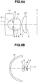
- Fig. 9A is a sectional view of an objective optical system according to example 9 of the present embodiment.
- Fig. 9B is a sectional view taken when the negative-powered, dome-shaped cover is placed on the object side of the objective optical system according to example 9 of the present embodiment.
- Fig. 9C is an aberration diagram of the objective optical system according to example 9 of the present embodiment.
- Table 9A shows numeric data on the objective optical system according to example 9 of the present embodiment.
- Table 9B shows numeric data obtained when the negative-powered, dome-shaped cover was placed on the object side of the objective optical system according to example 9 of the present embodiment. [Table 9A] Surface No.
- Fig. 10A is a sectional view of an objective optical system according to example 10 of the present embodiment.
- Fig. 10B is a sectional view taken when the negative-powered, dome-shaped cover is placed on the object side of the objective optical system according to example 10 of the present embodiment.
- Fig. 10C is an aberration diagram of the objective optical system according to example 10 of the present embodiment.
- Table 10A shows numeric data on the objective optical system according to example 10 of the present embodiment.
- Table 10B shows numeric data obtained when the negative-powered, dome-shaped cover was placed on the object side of the objective optical system according to example 10 of the present embodiment. [Table 10A] Surface No.
- Fig. 11A is a sectional view of an objective optical system according to example 11 of the present embodiment.
- Fig. 11B is a sectional view taken when the negative-powered, dome-shaped cover is placed on the object side of the objective optical system according to example 11 of the present embodiment.
- Fig. 11C is an aberration diagram of the objective optical system according to example 11 of the present embodiment.
- Table 11A shows numeric data on the objective optical system according to example 11 of the present embodiment.
- Table 11B shows numeric data obtained when the negative-powered, dome-shaped cover was placed on the object side of the objective optical system according to example 11 of the present embodiment. [Table 11A] Surface No.
- Fig. 12A is a sectional view of an objective optical system according to example 12 of the present embodiment.
- Fig. 12B is a sectional view taken when the negative-powered, dome-shaped cover is placed on the object side of the objective optical system according to example 12 of the present embodiment.
- Fig. 12C is an aberration diagram of the objective optical system according to example 12 of the present embodiment.
- Table 12A shows numeric data on the objective optical system according to example 12 of the present embodiment.
- Table 12B shows numeric data obtained when the negative-powered, dome-shaped cover was placed on the object side of the objective optical system according to example 12 of the present embodiment. [Table 12A] Surface No.
- Fig. 13A is a sectional view of an objective optical system according to example 13 of the present embodiment.
- Fig. 13B is a sectional view taken when the negative-powered, dome-shaped cover is placed on the object side of the objective optical system according to example 13 of the present embodiment.
- Fig. 13C is an aberration diagram of the objective optical system according to example 13 of the present embodiment.
- Table 13A shows numeric data on the objective optical system according to example 13 of the present embodiment.
- Table 13B shows numeric data obtained when the negative-powered, dome-shaped cover was placed on the object side of the objective optical system according to example 13 of the present embodiment. [Table 13A] Surface No.
- the groups of the objective optical systems in examples 1 to 11 and 13 are all made of the same resin material. This eliminates the need for processes and the like required when different resin materials are used, such as a manufacturing equipment cleaning process needed when resins are changed or a setup needed when manufacturing conditions are changed, and thereby realizes a still lower-cost objective optical system.
- the lens of the third group is made of a material with a lower Abbe number than the lens of the second group to correct chromatic difference of magnification.
- all the lenses can be made of a material with a refractive index of 1.65 or less.
- Typical materials with a refractive index of 1.65 or less include resin materials such as cycloolefin polymer, polycarbonate, acrylic, and polysulfone.
- the lenses can be manufactured from the resin materials at lower cost than from glass. Consequently, a wide-angle objective optical system with wide angle of view of 130 degrees or more can be manufactured at low cost.
- the endoscopic objective optical system is configured by placing the dome-shaped, transparent cover 13 on the object side of the objective optical system (on a distal end side of the apparatus) in an attempt to minimize friction with the body interior and thereby reduce the burden on the patient.
- Such a structure has a problem in that the beam is refracted by the dome-shaped cover 13, changing the angle of incidence on the objective optical system and resulting in changes in optical performance and imaging performance from when no cover 13 is used.
- the absolute value of the focal length of the dome-shaped cover 13 is set to be sufficiently larger than the absolute value of the focal length of the objective optical system, i.e., the following conditional expression is satisfied. 100 ⁇ f_d / f where f_d is the focal length of the dome-shaped cover 13 and f is the focal length of the entire objective optical system when the cover 13 is not placed.
- the absolute value of the focal length of the dome-shaped cover 13 is sufficiently larger than the absolute value of the focal length of the objective optical system (over 100 times as shown by the aforementioned conditional expression), and thus the dome-shaped cover 13 has a minimal effect with respect to power on the entire endoscopic objective optical system including the cover 13 and the objective optical system. Consequently, there is substantially no difference in observation performance whether or not the cover 13 is placed.
- sphere center positions on the object-side and image-side surfaces of the dome-shaped cover 13 are made to coincide with each other. Consequently, the beams passing through sphere centers are not refracted. This further reduces changes in the optical performance caused by the cover 13.
- Fig. 14 is a diagram showing a schematic configuration of principal part of a capsule endoscope 20 equipped with the objective optical system according to the present embodiment.
- the objective optical system 10 is housed in an objective frame 21. Also, the image pickup surface 11 of the image pickup device 12 is placed to coincide with the image plane position of the objective optical system 10. The image pickup device 12 has its position located by being abutted against part of the objective optical system 10.
- Illumination members such as LEDs 24 are placed around the objective optical system 10 and the image pickup device 12 to illuminate an object whose image is to be picked up.
- Illumination members such as LEDs 24 are placed at substantially symmetrical positions with respect to the objective optical system 10.
- the objective optical system 10, the image pickup device 12, and the LEDs 24 are placed on the object side of an exterior part 23 which makes up an enclosure of the capsule endoscope 20.
- the dome-shaped (e.g., substantially hemispherical) cover 13 made of a transparent material is placed, extending from the object side of the exterior part 23 to cover the objective optical system 10, the image pickup device 12, and the LEDs 24.
- the dome-shaped cover 13 has negative power on the optical axis of the objective optical system 10 as shown in Tables 1B to 13B.
- the exterior part 23 houses a substrate 25, a battery 27, and a radio apparatus 28, where electrical components 26 used to drive the image pickup device 12 and the LEDs 24 or to process images obtained by the image pickup device 12 are mounted on the substrate 25, the battery 27 is configured to serve as a power supply for the capsule endoscope 20, and the radio apparatus 28 is configured to transmit the obtained images to the outside and receive commands from the outside.
- Fig. 15 is a diagram showing a schematic configuration of a distal end portion 30 of an endoscope equipped with the objective optical system 10 according to the present embodiment.
- the objective optical system 10 is housed in an objective frame 21A. Also, the image pickup device 12 is held by an image pickup device frame 31. An outer circumference of the objective frame 21A is fitted in an inner circumference of the image pickup device frame 31 slidably along the optical axis.
- the image pickup device 12 and the objective optical system 10 are designed to have their positions located as the objective frame 21A and the image pickup device frame 31 are adjusted by sliding. The adjustment allows the image pickup surface 11 of the image pickup device 12 to be placed accurately at the image plane position of the objective optical system 10.
- Illumination lenses 33 which are illumination members configured to illuminate an object whose image is to be picked up are placed around the objective optical system 10.
- Light guides 32 configured to guide light from a light source device (not shown) to the illumination lenses 33 are placed behind the illumination lenses 33.
- a plurality (e.g., two) of illumination lenses 33 and light guides 32 are placed at substantially symmetrical positions with respect to the objective optical system 10.
- a transparent cover 13A is placed to cover the object side of the objective optical system 10 and the illumination lenses 33.
- the cover 13A creates a watertight and airtight seal in the endoscope except for inner part of a forceps hole 34 (described later).
- the cover 13A is a flat-shaped one which does not have power on the optical axis of the objective optical system 10 (and on optical axes of the illumination lenses 33).
- the forceps hole 34 is provided running from the distal end portion 30 of the endoscope to the user's hand side of the endoscope.
- the forceps hole 34 is configured to pass forceps and the like used for treatments and biopsies and is communicated to the outside by penetrating the cover 13A.
- a surface of the third group which is closest to the image side is coated to cut infrared radiation.
- the cover 13A is placed so as to cover the objective optical system 10, the illumination lenses 33, and the like at least on the object side, the lenses and the like of optical systems are not exposed to the outside, and thus to body fluids or the like.
- This allows lenses to be manufactured using a material, such as resin, which is inferior in durability to glass. Since resin materials are available relatively inexpensively, costs of the objective optical system 10, the illumination lenses 33, and the like can be reduced further.
- the objective optical system according to the present embodiment is suitable for small apparatus which require a wide observation field of view.
- Concrete application examples include endoscopes and capsule endoscopes.
- the objective optical system according to the present embodiment is useful, especially for disposable types which are desired to be low in cost.
- the embodiment provides an objective optical system with a wide angle of 130 degrees or more quite serviceable for use in endoscopes at low cost while achieving downsizing by reducing the number of lenses.
- the present invention is not limited to the precise embodiment described above and may be embodied by changing components in the implementation stage without departing from the invention.
- the invention can be implemented in various forms using appropriate combinations of the components disclosed in the above embodiment. For example, some of the components disclosed in the embodiment may be deleted. Furthermore, components may be combined as required across different embodiments. Thus, it is needless to say that various alterations and applications are possible without departing from the invention.
Landscapes
- Health & Medical Sciences (AREA)
- Life Sciences & Earth Sciences (AREA)
- Physics & Mathematics (AREA)
- Surgery (AREA)
- Optics & Photonics (AREA)
- Biomedical Technology (AREA)
- Animal Behavior & Ethology (AREA)
- Radiology & Medical Imaging (AREA)
- Nuclear Medicine, Radiotherapy & Molecular Imaging (AREA)
- Engineering & Computer Science (AREA)
- Biophysics (AREA)
- Heart & Thoracic Surgery (AREA)
- Medical Informatics (AREA)
- Molecular Biology (AREA)
- Pathology (AREA)
- General Health & Medical Sciences (AREA)
- Public Health (AREA)
- Veterinary Medicine (AREA)
- General Physics & Mathematics (AREA)
- Lenses (AREA)
- Instruments For Viewing The Inside Of Hollow Bodies (AREA)
- Endoscopes (AREA)
Description
- The present invention relates to an objective optical system, and more particularly, to an objective optical system which has a wide angle of view and can be used in endoscopes and the like.
- Conventionally, various techniques have been proposed to reduce components in objective optical systems for endoscopes or objective optical systems for digital cameras and thereby reduce costs.
- As an example of such techniques, Japanese Patent Application Laid-Open Publication No.
5-307139 - Also, Japanese Patent Application Laid-Open Publication No.
2002-350720 - Incidentally, a conceivable measure for reducing costs is to first reduce the number of lenses. However, if the number of lenses is reduced too much, there would be a case where aberration correction becomes insufficient. In products such as endoscopes for which widening of angle of view is desired, in particular, if sufficient aberration correction is intended to be performed, widening of angle of view cannot be achieved. Therefore, it is a technical problem to be solved that how both aberration correction and widening of angle of view can be achieved. An angle of view which is desirable for endoscope objective optical systems is generally a wide angle of 130 degrees or more.
- In addition, in endoscopes, capsule endoscopes and the like, in order to ease burden on a patient as much as possible and improve operability for an operator, it is desirable that distal end rigid portions of endoscopes and entire lengths of capsule endoscopes are reduced. Therefore, also regarding objective optical systems mounted on endoscopes, capsule endoscopes and the like, the lengths in an optical axis direction are required to be reduced. Accordingly, it is important to reduce the entire length as much as possible not only by reducing the number of lenses but also by devising arrangement of lenses.
- Furthermore, there is a desire for providing objective optical systems at a low cost. However, in order to do so, it is necessary not only to reduce the number of lenses but also to use low-cost materials as materials for manufacturing lenses. Glass materials, resins and the like are known as materials for manufacturing lenses, and among such materials, resins are relatively cheap. Therefore, in order to reduce costs, it is necessary to use resins as materials. However, lower-cost resins have lower refractive indices in many cases. Therefore, it is necessary to devise manufacturing so as to achieve widening of angle of view, size reduction and the like even in a case of using a resin having a relatively low refractive index.
- However, the above-described Japanese Patent Application Laid-Open Publication No.
5-307139 - In addition, the above-described Japanese Patent Application Laid-Open Publication No.
2002-350720 us 2009/0141364 A1 discloses an imaging system for a capsule endoscope. - The present invention has been achieved in view of the above-described circumstances and an object of the present invention is to provide an objective optical system which has a wide angle of view and reduced size and which is low cost.
- In order to achieve the above-described object, an objective optical system according to an aspect of the present invention, which is disclosed in
claim 1, includes, in order from an object side, a negative-powered first group, an aperture stop, a positive-powered second group, and a according to an aspect of the present invention, includes, in order from an object side, an aperture third group, wherein: a surface of the first group which is closest to an image side is a concave surface; a surface of the second group which is closest to the image side is an aspheric surface; a surface of the third group which is closest to the object side is a convex surface; and a distance between the second group and the third group is smaller than a distance between the first group and the second group, satisfying a conditional expression below
- According to another aspect of the present invention, there is provided an endoscopic objective optical system comprising: the objective optical system; and a cover placed closer to the object side than a surface of the first group which is closest to the object side.
-
-
Fig. 1A is a sectional view of an objective optical system according to example 1 of an embodiment of the present invention; -
Fig. 1B is a sectional view taken when a negative-powered, dome-shaped cover is placed on an object side of the objective optical system according to example 1 of the embodiment; -
Fig. 1C is an aberration diagram of the objective optical system according to example 1 of the embodiment; -
Fig. 2A is a sectional view of an objective optical system according to example 2 of the embodiment; -
Fig. 2B is a sectional view taken when the negative-powered, dome-shaped cover is placed on an object side of the objective optical system according to example 2 of the embodiment; -
Fig. 2C is an aberration diagram of the objective optical system according to example 2 of the embodiment; -
Fig. 3A is a sectional view of an objective optical system according to example 3 of the embodiment; -
Fig. 3B is a sectional view taken when the negative-powered, dome-shaped cover is placed on an object side of the objective optical system according to example 3 of the embodiment; -
Fig. 3C is an aberration diagram of the objective optical system according to example 3 of the embodiment; -
Fig. 4A is a sectional view of an objective optical system according to example 4 of the embodiment; -
Fig. 4B is a sectional view taken when the negative-powered, dome-shaped cover is placed on an object side of the objective optical system according to example 4 of the embodiment; -
Fig. 4C is an aberration diagram of the objective optical system according to example 4 of the embodiment; -
Fig. 5A is a sectional view of an objective optical system according to example 5 of the embodiment; -
Fig. 5B is a sectional view taken when the negative-powered, dome-shaped cover is placed on an object side of the objective optical system according to example 5 of the embodiment; -
Fig. 5C is an aberration diagram of the objective optical system according to example 5 of the embodiment; -
Fig. 6A is a sectional view of an objective optical system according to example 6 of the embodiment; -
Fig. 6B is a sectional view taken when the negative-powered, dome-shaped cover is placed on an object side of the objective optical system according to example 6 of the embodiment; -
Fig. 6C is an aberration diagram of the objective optical system according to example 6 of the embodiment; -
Fig. 7A is a sectional view of an objective optical system according to example 7 of the embodiment; -
Fig. 7B is a sectional view taken when the negative-powered, dome-shaped cover is placed on an object side of the objective optical system according to example 7 of the embodiment; -
Fig. 7C is an aberration diagram of the objective optical system according to example 7 of the embodiment; -
Fig. 8A is a sectional view of an objective optical system according to example 8 of the embodiment; -
Fig. 8B is a sectional view taken when the negative-powered, dome-shaped cover is placed on an object side of the objective optical system according to example 8 of the embodiment; -
Fig. 8C is an aberration diagram of the objective optical system according to example 8 of the embodiment; -
Fig. 9A is a sectional view of an objective optical system according to example 9 of the embodiment; -
Fig. 9B is a sectional view taken when the negative-powered, dome-shaped cover is placed on an object side of the objective optical system according to example 9 of the embodiment; -
Fig. 9C is an aberration diagram of the objective optical system according to example 9 of the embodiment; -
Fig. 10A is a sectional view of an objective optical system according to example 10 of the embodiment; -
Fig. 10B is a sectional view taken when the negative-powered, dome-shaped cover is placed on an object side of the objective optical system according to example 10 of the embodiment; -
Fig. 10C is an aberration diagram of the objective optical system according to example 10 of the embodiment; -
Fig. 11A is a sectional view of an objective optical system according to example 11 of the embodiment; -
Fig. 11B is a sectional view taken when the negative-powered, dome-shaped cover is placed on an object side of the objective optical system according to example 11 of the embodiment; -
Fig. 11C is an aberration diagram of the objective optical system according to example 11 of the embodiment; -
Fig. 12A is a sectional view of an objective optical system according to example 12 of the embodiment; -
Fig. 12B is a sectional view taken when the negative-powered, dome-shaped cover is placed on an object side of the objective optical system according to example 12 of the embodiment; -
Fig. 12C is an aberration diagram of the objective optical system according to example 12 of the embodiment; -
Fig. 13A is a sectional view of an objective optical system according to example 13 of the embodiment; -
Fig. 13B is a sectional view taken when the negative-powered, dome-shaped cover is placed on an object side of the objective optical system according to example 13 of the embodiment; -
Fig. 13C is an aberration diagram of the objective optical system according to example 13 of the embodiment; -
Fig. 14 is a diagram showing a schematic configuration of principal part of a capsule endoscope equipped with the objective optical system according to the embodiment; -
Fig. 15 is a diagram showing a schematic configuration of a distal end portion of an endoscope equipped with the objective optical system according to the embodiment; and -
Fig. 16 is a diagram showing a schematic configuration of the objective optical system according to the embodiment. - An embodiment of the present invention will be described below with reference to the drawings.
- The invention is defined in the claims. Other embodiments are merely exemplary.
-
Figs. 1A to 16 show an embodiment of the present disclosure. - An objective optical system according to the present embodiment includes, in order from an object side, a negative-powered first group, an aperture stop, an aperture a positive-powered second group, and a third group. A surface of the first group which is closest to an image side is a concave surface, a surface of the second group which is closest to the image side is an aspheric surface, and a surface of the third group which is closest to the object side is a convex surface. The second group and the third group are placed close to each other such that a distance between the second group and the third group will be smaller than a distance between the first group and the second group.
- A configuration of the objective optical system will be described concretely with reference to
Fig. 16 as follows. - In an objective
optical system 10 shown inFig. 16 , each group is made up of one single lens: the first group consists of a first lens L1, the second group consists of a second lens L2, and the third group consists of a third lens L3. A lens stop S is placed between the first lens L1 and the second lens L2. Furthermore, in the example shown inFig. 16 , animage pickup surface 11 of animage pickup device 12 is placed at an image plane position of the objectiveoptical system 10. - Optical surfaces of the objective
optical system 10 are as follows, in order from the object side. - That is,
surface 1 is an object-side surface of the first lens L1,surface 2 is an image-side surface of the first lens L1,surface 3 is the aperture stop S,surface 4 is an entrance pupil,surface 5 is an object-side surface of the second lens L2,surface 6 is an image-side surface of the second lens L2,surface 7 is an object-side surface of the third lens L3, andsurface 8 is an image-side surface of the third lens L3. However, regardingsurface 3 andsurface 4, in some of the examples described later, the entrance pupil issurface 3 and the lens stop S issurface 4. -
Surface 2 on the image side of thefirst lens L 1 is a concave surface,surface 6 on the image side of the second lens L2 is an aspheric surface, andsurface 7 on the object side of the third lens L3 is a convex surface. Furthermore, the objectiveoptical system 10 is placed such that a distance d_L23 betweensurface 6 of the second lens L2 andsurface 7 of the third lens L3 along an optical axis will be smaller than a distance d L12 betweensurface 2 of the first lens L1 andsurface 5 of the second lens L2 along the optical axis. Incidentally, a detailed conditional expression to be satisfied by the distance d_L12 and the distance d_L23 will be described later. - Next, optical functions of each group will be described below.
- The first group is an element which mainly acts to implement a wide-angle capability. In particular, the surface on the object side plays a role in achieving the wide-angle capability (as can be seen from an off-axis luminous flux in the example shown in
Fig. 16 , onsurface 1 on the object side of the first lens L1, incident light from a wide-angle side is refracted greatly in a direction of an image plane 11 (an incident angle is large and refracting angle is small)). In order to give a wide-angle capability to an objective optical system, it is necessary to reduce a focal length of the entire system, but if the focal lengths are reduced with use of only positive-powered groups, strong field curvature will occur. Therefore, to implement a wide-angle capability while correcting field curvature, it is necessary to place a negative-powered group in the optical system. In so doing, to reduce the number of lenses and downsize the optical system, limited placement locations are available, and desirably a negative-powered group is placed on the object side of the lens stop. Thus, according to the present embodiment, the first group closest to the object side is a negative-powered group. - The second group is an element which mainly has an image-forming function and an aberration correction effect. Since the first group has negative power as described above, a luminous flux passing through the first group becomes a diverging luminous flux (as can be seen from an axial luminous flux and an off-axis luminous flux in the example shown in
Fig. 16 , a luminous flux emitted from the first lens L1 diverges with an expanded flux width). Therefore, to change the diverging luminous flux into converging light, it is necessary to give relatively high positive power to the second group. However, it is known that high-power lenses are generally prone to aberrations. Thus, according to the present embodiment, an aspheric surface is used as the surface of the second group which is closest to the image side (surface 6 in the example shown inFig. 16 ) to minimize generation of aberrations. - The third group is an element which mainly acts to maximize efficiency of incidence on the image pickup device, and in particular, plays a role in performing control so that the surface (
surface 8 in the example shown inFig. 16 ) on the image side will provide an incidence angle suitable for characteristics (described later) of the image pickup device. However, if the third group is used for aberration correction, it becomes difficult to control the incidence angle on the image pickup device. Thus, according to the present embodiment, the third group has relatively low power. - Next, arrangement of the groups will be described.
- The distance between the first group and the second group is set to be large (i.e., the first group and the second group are placed away from each other) in order to enhance a wide-angle effect of the first group. That is, to refract a beam efficiently, it is advisable to place the lenses so as to cause the beam to pass through an outer region of the lenses. Thus, according to the present embodiment, a distance from the surface (
surface 1 in the example shown inFig. 16 ) of the first group which is closest to the object side to a surface of the lens stop is increased. Consequently, when passing through the first group, the beam passes through an outer part of the lens, and a wide-angle capability may be achieved efficiently. - On the other hand, the distance between the second group and the third group is minimized. This is because reducing the distance between the second group and the third group reduces the focal length of the objective optical system, giving a wide-angle capability to the objective optical system.
- Thus, in the present embodiment, to implement the wide-angle capability efficiently, the distance between the first group and the second group is increased and the distance between the second group and the third group is reduced. In this way, after the distance between the second group and the third group is minimized, the distance between the first group and the second group is optimized. This eliminates the need to increase the distance between the second group and the third group more than necessary, making it possible to implement the wide-angle capability while keeping the total length to a minimum.
- Furthermore, if the following conditional expression is satisfied, even when a low-refractive-index material such as resin is used, the distances among the groups can be set in a balanced manner, allowing the wide-angle capability to be implemented with the total length kept to a minimum.

- Also, with recent image pickup devices, it is common practice to provide a microlens, a color filter, or the like on an image pickup surface on which multiple photo diodes for photoelectric conversion are arrayed, where the microlens is provided to increase an aperture ratio and the color filter is provided to implement a single color image pickup device. Light passing through the objective optical system and entering such an image pickup device, for example, at a large incident angle may be kicked by edges of the microlens or color filter, thereby failing to reach the image pickup surface. Consequently, an outer part of an image resulting from the large incident angle undergoes less photoelectric conversion than a central part of the image, causing a phenomenon in which an outer region of the image becomes dark. In this way, it is known that image pickup devices vary in characteristics depending on the incident angle of a light flux. Thus, according to the present embodiment, the darkening of the outer region of the image is bettered by controlling the incident angle on the image pickup device using the third group.
- In addition, if the lenses are arranged so as to satisfy the following conditional expression, the incident angle on the image pickup device can be controlled efficiently using the third group while performing sufficient aberration correction using the second group.

- To achieve a wide angle of view using an inexpensive, but low-refractive-index material such as resin, it is advisable to give power to all the surfaces of all the lenses. Then, the number of lenses in each group can be reduced to one. Such configuration examples are shown in the examples described below as well as in the example shown in
Fig. 16 . Thus, it is possible to implement a wide-angle objective optical system with an angle of view of 130 degrees or more using a three-group, three-lens configuration. - Concrete examples of the objective optical system according to the present embodiment will be shown below. Incidentally, an aspheric expression as given by
Expression 1 was used to calculate numeric data on the objective optical systems in the following examples.
- Z: distance from an apex of an aspheric surface along an optical axis of the aspheric surface at a point at height h from the optical axis
- h: height from the optical axis
- k: conical constant
- A4 to 10: fourth- to tenth-order aspheric coefficients
- R: paraxial radius of curvature
- Also,
Figs. 1B to 11B illustrate how an endoscopic objective optical system is configured by further placing a dome-shaped, negative-powered,transparent cover 13 closer to the object than is the first group of the objective optical system to improve insertability of an endoscope or a capsule endoscope. Tables 1B to 11B show numeric data obtained when the dome-shapedcover 13 is placed. Object position in Tables 1B to 11B is the distance from the surface apex of the surface of the dome-shapedcover 13 which is located on the object side. -
Fig. 1A is a sectional view of an objective optical system according to example 1 of the present embodiment.Fig. 1B is a sectional view taken when the negative-powered, dome-shaped cover is placed on the object side of the objective optical system according to example 1 of the present embodiment.Fig. 1C is an aberration diagram of the objective optical system according to example 1 of the present embodiment. Table 1 A shows numeric data on the objective optical system according to example 1 of the present embodiment. Table 1B shows numeric data obtained when the negative-powered, dome-shaped cover was placed on the object side of the objective optical system according to example 1 of the present embodiment.[Table 1A] Surface No. R D Nd Vd Object position INF 14.1343 1 7.3896 0.3855 1.5311 56 2(Aspheric surface) 1.5604 0.1939 3(Lens stop) INF 0.0694 4 INF 0.0353 5 2.0358 0.8346 1.5311 56 6(Aspheric surface) -0.7486 0.0600 7 2.5058 0.6926 1.5311 56 8(Aspheric surface) -14.1650 0.6198 Image location INF Aspheric surface data Surface No. K A4 A6 A8 A10 2 0.045721 1.0945E-01 -1.3813E-01 -4.3160E-01 6 -1.3527 -4.4434E-02 -4.4789E-02 3.0478E-01 3.1421E-05 8 9.5581 -1.3634E-01 -1.3881E-03 8.4316E-02 3.8101E-06 Focal length of entire system 1.0000 Focal length of first lens -3.7961 Focal length of second lens 1.1456 Focal length of third lens 4.0505 Effective f-No. 3.3638 Center magnification -0.07020 Front focus position 0.1106 Rear focus position -0.0551 Maximum image height 1.0074 Half view angle at maximum image height -69.05 Incident angle on image pickup device at maximum image height -10.63 d_L23/d_L12 0.201 |f_L3/f_L2| 3.536 [Table 1B] Surface No. R D Nd Vd Object position 9.1231 Object-side surface of dome 6.9387 0.6425 1.585 30 Image-side surface of dome surface of 6.2962 6.1292 Object-side first lens 7.3896 0.3855 1.5311 56 Focal length of entire system 1.0003 Focal length of dome -183.331 Effective f-No. 3.3607 Center magnification -0.06250 Front focus position 6.8822 Rear focus position -0.0497 Half view angle at maximum image height -69.08 Incident angle on image pickup device at maximum image height -10.63 |f_d/f| 183.331 -
Fig. 2A is a sectional view of an objective optical system according to example 2 of the present embodiment.Fig. 2B is a sectional view taken when the negative-powered, dome-shaped cover is placed on the object side of the objective optical system according to example 2 of the present embodiment.Fig. 2C is an aberration diagram of the objective optical system according to example 2 of the present embodiment. Table 2A shows numeric data on the objective optical system according to example 2 of the present embodiment. Table 2B shows numeric data obtained when the negative-powered, dome-shaped cover was placed on the object side of the objective optical system according to example 2 of the present embodiment.[Table 2A] Surface No. R D N V Object position INF 11.8895 1 14.4669 0.3963 1.5311 56 2 1.6791 0.2510 3(Lens stop) INF 0.0713 4 INF 0.0396 5 2.6421 0.7926 1.5311 56 6(Aspheric surface) -0.7385 0.0661 7 2.4532 0.6605 1.5311 56 8 -22.6997 0.7134 Image location INF Aspheric surface data Surface No. K A4 A6 A8 A10 6 -1.4115 -1.1074E-01 -5.4402E-02 2.7571E-01 3.1256E-03 Focal length of entire system 1.0000 Focal length of first lens -3.6003 Focal length of second lens 1.1782 Focal length of third lens 4.1892 Effective f-No. 3.5199 Center magnification -0.08306 Front focus position 0.1495 Rear focus position -0.0665 Maximum image height 1.0357 Half view angle at maximum image height -69.79 Incident angle on image pickup device at maximum image height -14.87 d_L23/d_L12 0.182 |f_L3/f_L2| 3.556 [Table 2B] Surface No. R D N V Object position INF 5.9448 Object-side surface of dome 7.1337 0.6605 1.585 30 Image-side surface of dome 6.4732 6.3014 Object-side surface of first lens 14.4669 0.3963 1.5311 56 Focal length of entire system 1.0001 Focal length of dome -188.484 Effective f-No. 3.5182 Center magnification -0.07660 Front focus position 7.1115 Rear focus position -0.0612 Half view angle at maximum image height -69.82 Incident angle on image pickup device at maximum image height -14.87 |f_d/f| 188.484 -
Fig. 3A is a sectional view of an objective optical system according to example 3 of the present embodiment.Fig. 3B is a sectional view taken when the negative-powered, dome-shaped cover is placed on the object side of the objective optical system according to example 3 of the present embodiment.Fig. 3C is an aberration diagram of the objective optical system according to example 3 of the present embodiment. Table 3A shows numeric data on the objective optical system according to example 3 of the present embodiment. Table 3B shows numeric data obtained when the negative-powered, dome-shaped cover was placed on the object side of the objective optical system according to example 3 of the present embodiment.[Table 3A] Surface No. R D N V Object position INF 11.0521 1 5.6426 0.3725 1.5311 56 2(Aspheric surface) 1.0454 0.6914 3(Lens stop) INF 0.0671 4 INF 0.0373 5 5.1280 0.9853 1.5311 56 6(Aspheric surface) -0.8394 0.0744 7 1.9862 0.8983 1.5311 56 8(Aspheric surface) 9.0286 0.8729 Image location INF Aspheric surface data Surface No. K A4 A6 A8 2 -1.5876 1.3440E-01 -1.1830E+00 3.9155E+00 6 0.064393 1.6094E-01 5.9809E-01 -1.2347E-01 8 64.337 1.1708E-01 -3.6287E-01 1.6941E-01 Focal length of entire system 1.0000 Focal length of first lens -2.4755 Focal length of second lens 1.4348 Focal length of third lens 4.5714 Effective f-No. 3.4291 Center magnification -0.08641 Front focus position 0.5201 Rear focus position -0.0650 Maximum image height 0.9736 Half view angle at maximum image height -72.55 Incident angle on image pickup device at maximum image height -7.67 d_L23/d_L12 0.094 |f_L3/f_L2| 3.186 [Table 3B] Surface No. R D N V Object position INF 5.2156 Object-side surface of dome 6.7058 0.6209 1.585 30 Image-side surface of dome 6.0849 5.9235 Object-side surface of first lens 5.6426 0.3725 1.5311 56 Focal length of entire system 0.9980 Focal length of dome -177.170 Effective f-No. 3.4294 Center magnification -0.08127 Front focus position 7.0637 Rear focus position -0.0594 Half view angle at maximum image height -72.64 Incident angle on image pickup device at maximum image height -7.67 |f_d/f| 177.17 -
Fig. 4A is a sectional view of an objective optical system according to example 4 of the present embodiment.Fig. 4B is a sectional view taken when the negative-powered, dome-shaped cover is placed on the object side of the objective optical system according to example 4 of the present embodiment.Fig. 4C is an aberration diagram of the objective optical system according to example 4 of the present embodiment. Table 4A shows numeric data on the objective optical system according to example 4 of the present embodiment. Table 4B shows numeric data obtained when the negative-powered, dome-shaped cover was placed on the object side of the objective optical system according to example 4 of the present embodiment.[Table 4A] Surface No. R D N V Object position INF 16.5665 1(Aspheric surface) 7.8209 0.5370 1.5311 56 2(Aspheric surface) 1.4327 1.2892 3(Lens stop) INF 0.0540 4 INF 0.0540 5(Aspheric surface) -7.8509 0.9104 1.5311 56 6(Aspheric surface) -0.7221 0.0720 7(Aspheric surface) 1.6493 0.8345 1.5311 56 8(Aspheric surface) 1.4496 0.9004 Image location INF Aspheric surface data Surface No. K A4 A6 1 1.8868E-02 -1.9652E-03 2 5.5233E-02 2.2400E-01 5 -6.9578E-01 6 7.1635E-02 3.1279E-01 7 -1.0422E-01 8 -2.5481E-01 3.5748E-02 Focal length of entire system 1.0000 Focal length of first lens -3.3876 Focal length of second lens 1.4277 Focal length of third lens 49.4865 Effective f-No. 3.0171 Center magnification -0.05721 Front focus position 0.9135 Rear focus position -0.0526 Maximum image height 1.1453 Half view angle at maximum image height -81.46 Incident angle on image pickup device at maximum image height -17.60 d_L23/d_L12 0.052 |f_L3/f_L2| 34.663 [Table 4B] Surface No. R D N V Object position INF 10.4441 Object-side surface of dome 8.1032 0.9004 1.585 30 Image-side surface of dome 7.2028 6.6626 Object-side surface of first lens 7.8209 0.5370 1.5311 56 Focal length of entire system 0.9979 Focal length of dome -174.774 Effective f-No. 3.0186 Center magnification -0.05274 Front focus position 8.4757 Rear focus position -0.0469 Half view angle at maximum image height -81.53 Incident angle on image pickup device at maximum image height -17.60 |f_d/f| 174.774 -
Fig. 5A is a sectional view of an objective optical system according to example 5 of the present embodiment.Fig. 5B is a sectional view taken when the negative-powered, dome-shaped cover is placed on the object side of the objective optical system according to example 5 of the present embodiment.Fig. 5C is an aberration diagram of the objective optical system according to example 5 of the present embodiment. Table 5A shows numeric data on the objective optical system according to example 5 of the present embodiment. Table 5B shows numeric data obtained when the negative-powered, dome-shaped cover was placed on the object side of the objective optical system according to example 5 of the present embodiment.[Table 5A] Surface No. R D N V Object position INF 11.8486 1 5.2149 0.3742 1.5311 56 2(Aspheric surface) 0.9042 0.7313 3(Lens stop) INF 0.0673 4 INF 0.0374 5 4.5599 0.9471 1.5311 56 6(Aspheric surface) -0.8677 0.1704 7 1.9959 0.6694 1.5311 56 8(Aspheric surface) 14.5387 1.0601 Image location INF Aspheric surface data Surface No. K A4 A6 A8 2 -1.2612 3.4591E-02 8.7515E-01 1.9601E+00 6 0.46072 2.0354E-01 2.7578E-02 1.6001E+00 8 -222.68 1.3935E-01 -3.1091E-01 1.6170E-01 Focal length of entire system 1.0000 Focal length of first lens -2.1147 Focal length of second lens 1.4551 Focal length of third lens 4.2585 Effective f-No. 4.2105 Center magnification -0.08072 Front focus position 0.5400 Rear focus position -0.0597 Maximum image height 0.9778 Half view angle at maximum image height -72.22 Incident angle on image pickup device at maximum image height -10.00 d_L23/d_L12 0.204 |f_L3/f_L2| 2.927 [Table 5B] Surface No. R D N V Object position INF 6.2361 Object-side surface of dome 6.7350 0.6236 1.585 30 Image-side surface of dome 6.1114 5.9492 Object-side surface of first lens 5.2149 0.3742 1.5311 56 Focal length of entire system 0.9979 Focal length of dome -177.949 Effective f-No. 4.2095 Center magnification -0.07476 Front focus position 7.1120 Rear focus position -0.0541 Half view angle at maximum image height -72.31 Incident angle on image pickup device at maximum image height -10.00 |f_d/f| 177.949 -
Fig. 6A is a sectional view of an objective optical system according to example 6 of the present embodiment.Fig. 6B is a sectional view taken when the negative-powered, dome-shaped cover is placed on the object side of the objective optical system according to example 6 of the present embodiment.Fig. 6C is an aberration diagram of the objective optical system according to example 6 of the present embodiment. Table 6A shows numeric data on the objective optical system according to example 6 of the present embodiment. Table 6B shows numeric data obtained when the negative-powered, dome-shaped cover was placed on the object side of the objective optical system according to example 6 of the present embodiment.[Table 6A] Surface No. R D N V Object position INF 12.9792 1 5.7108 0.4099 1.5311 56 2(Aspheric surface) 0.9543 0.8932 3(Lens stop) INF 0.0738 4 INF 0.0410 5 3.9789 1.2960 1.5311 56 6(Aspheric surface) -0.6818 0.0814 7 2.1867 0.5263 1.5311 56 8(Aspheric surface) 1.3968 1.0970 Image location INF Aspheric surface data Surface No. K A4 A6 A8 A10 2 -5.6757 6.0331E-01 -1.3818E+00 2.6447E+00 6 -0.4354 2.6069E-01 2.3687E-01 2.0363E-01 8 -1.1108 -5.8591E-02 -2.3745E-01 1.7967E-01 -3.2030E-02 Focal length of entire system 1.0000 Focal length of first lens -2.2147 Focal length of second lens 1.2081 Focal length of third lens -9.4372 Effective f-No. 3.4924 Center magnification -0.07329 Front focus position 0.6644 Rear focus position -0.0160 Maximum image height 1.0711 Half view angle at maximum image height -74.26 Incident angle on image pickup device at maximum image height -12.07 d_L23/d_L12 0.081 |f_L3/f_L2| 7.811 [Table 6B] Surface No. R D N V Object position INF 6.4213 Object-side surface of dome 7.3776 0.6831 1.585 30 Image-side surface of dome 6.6945 6.5169 Object-side surface of first lens 5.7108 0.4099 1.5311 56 Focal length of entire system 0.9975 Focal length of dome -194.929 Effective f-No. 3.4940 Center magnification -0.06983 Front focus position 7.8632 Rear focus position -0.0109 Half view angle at maximum image height -74.35 Incident angle on image pickup device at maximum image height -12.07 |f_d/f| 194.929 -
Fig. 7A is a sectional view of an objective optical system according to example 7 of the present embodiment.Fig. 7B is a sectional view taken when the negative-powered, dome-shaped cover is placed on the object side of the objective optical system according to example 7 of the present embodiment.Fig. 7C is an aberration diagram of the objective optical system according to example 7 of the present embodiment. Table 7A shows numeric data on the objective optical system according to example 7 of the present embodiment. Table 7B shows numeric data obtained when the negative-powered, dome-shaped cover was placed on the object side of the objective optical system according to example 7 of the present embodiment.[Table 7A] Surface No. R D N V Object position INF 18.9819 1 (Aspheric surface) 2.7444 0.5593 1.5311 56 2(Aspheric surface) 0.7887 0.9081 3 INF 0.0569 4(Lens stop) INF 0.0402 5(Aspheric surface) -3.8655 1.1172 1.5311 56 6(Aspheric surface) -0.8132 0.0759 7(Aspheric surface) 2.1721 1.2027 1.5311 56 8(Aspheric surface) 80.6168 1.0281 Image location INF Aspheric surface data Surface No. K A4 A6 A8 1 7.4011E-04 2 -8.0726E-02 -5.4748E-02 5 -5.5506E-01 1.0502E-01 6 -0.1337 4.8698E-02 5.6774E-02 8.7166E-03 7 5.2121E-03 -2.4712E-02 8 3048.7000 1.3836E-02 -4.6871E-02 5.9748E-03 Focal length of entire system 1.0000 Focal length of first lens -2.3045 Focal length of second lens 1.7128 Focal length of third lens 4.1630 Effective f-No. 3.0013 Center magnification -0.05021 Front focus position 0.9358 Rear focus position -0.0422 Maximum image height 1.2073 Half view angle at maximum image height -81.50 Incident angle on image pickup device at maximum image height -4.35 d_L23/d_L12 0.076 |f_L3/f_L2| 2.431 [Table 7B] Surface No. R D N V Object position INF 12.3382 Object-side surface of dome 8.5419 0.9491 1.585 30 Image-side surface of dome 7.5928 8.1622 Object-side surface of first lens 2.7444 0.5593 1.5311 56 Focal length of entire system 0.9919 Focal length of dome -184.237 Effective f-No. 3.0008 Center magnification -0.04433 Front focus position 10.0349 Rear focus position -0.0368 Half view angle at maximum image height -81.98 Incident angle on image pickup device at maximum image height -4.35 |f_d/f| 184.237 -
Fig. 8A is a sectional view of an objective optical system according to example 8 of the present embodiment.Fig. 8B is a sectional view taken when the negative-powered, dome-shaped cover is placed on the object side of the objective optical system according to example 8 of the present embodiment.Fig. 8C is an aberration diagram of the objective optical system according to example 8 of the present embodiment. Table 8A shows numeric data on the objective optical system according to example 8 of the present embodiment. Table 8B shows numeric data obtained when the negative-powered, dome-shaped cover was placed on the object side of the objective optical system according to example 8 of the present embodiment.[Table 8A] Surface No. R D N V Object position INF 20.5324 1(Aspheric surface) 4.1011 0.6435 1.5311 56 2(Aspheric surface) 0.8615 1.1301 3 INF 0.0648 4(Lens stop) INF 0.0417 5(Aspheric surface) -5.4544 1.2802 1.5311 56 6(Aspheric surface) -0.9233 0.0865 7(Aspheric surface) 2.3400 1.2545 1.5311 56 8(Aspheric surface) 90.1975 1.1766 Image location INF Aspheric surface data Surface No. K A4 A6 AS 1 3.4526E-02 -3.0652E-03 2 -1.6133E-02 9.9237E-02 5 -3.6191E-01 1.1123E-02 6 -0.1600 3.4563E-02 6.5255E-02 -6.1639E-02 7 9.0842E-03 -1.8233E-02 8 3053.9000 2.5947E-02 -3.0978E-02 2.5270E-03 Focal length of entire system 1.0000 Focal length of first lens -2.1967 Focal length of second lens 1.8975 Focal length of third lens 4.4819 Effective f-No. 3.0085 Center magnification -0.04623 Front focus position 1.0963 Rear focus position -0.0370 Maximum image height 1.3746 Half view angle at maximum image height -81.50 Incident angle on image pickup device at maximum image height -4.38 d_L23/d_L12 0.070 |f_L3/f_L2| 2.362 [Table 8B] Surface No. R D N V Object position INF 11.8872 Object-side surface of dome 9.7259 1.0807 1.585 30 Image-side surface of dome 8.6452 9.2936 Object-side surface of first lens 4.1011 0.6435 1.5311 56 Focal length of entire system 0.9918 Focal length of dome -209.774 Effective f-No. 3.0090 Center magnification -0.04249 Front focus position 11.4562 Rear focus position -0.0323 Half view angle at maximum image height -82.03 Incident angle on image pickup device at maximum image height -4.38 |f_d/f| 209.774 -
Fig. 9A is a sectional view of an objective optical system according to example 9 of the present embodiment.Fig. 9B is a sectional view taken when the negative-powered, dome-shaped cover is placed on the object side of the objective optical system according to example 9 of the present embodiment.Fig. 9C is an aberration diagram of the objective optical system according to example 9 of the present embodiment. Table 9A shows numeric data on the objective optical system according to example 9 of the present embodiment. Table 9B shows numeric data obtained when the negative-powered, dome-shaped cover was placed on the object side of the objective optical system according to example 9 of the present embodiment.[Table 9A] Surface No. R D N V Object position INF 12.9904 1 8.4387 0.4102 1.5311 56 2(Aspheric surface) 0.6793 0.7001 3(Lens stop) INF 0.0738 4 INF 0.0410 5 3.5183 1.0150 1.5311 56 6(Aspheric surface) -0.9985 0.1311 7 2.1890 0.5267 1.5311 56 8(Aspheric surface) -24.4866 1.5332 Image location INF Aspheric surface data Surface No. K A4 A6 A8 2 -1.25710 5.1682E-01 2.8141E+00 -3.5807E+00 6 0.52500 1.6922E-01 -5.6605E-02 4.1504E-01 8 -4019.70000 -1.9618E-02 9.5606E-02 -1.3301E-02 Focal length of entire system 1.0000 Focal length of first lens -1.4110 Focal length of second lens 1.5819 Focal length of third lens 3.7934 Effective f-No. 3.4956 Center magnification -0.07403 Front focus position 0.5183 Rear focus position -0.0619 Maximum image height 1.0721 Half view angle at maximum image height -72.25 Incident angle on image pickup device at maximum image height -13.05 d_L23/d_L12 0.161 |f_L3/f_L2| 2.398 [Table 9B] Surface No. R D N V Object position INF 6.4268 Object-side surface of dome 7.3840 0.6837 1.585 30 Image-side surface of dome 6.7003 6.5225 Object-side surface of first lens 8.4387 0.4102 1.5311 56 Focal length of entire system 0.9983 Focal length of dome -195.097 Effective f-No. 3.4971 Center magnification -0.07054 Front focus position 7.7240 Rear focus position -0.0567 Half view angle at maximum image height -72.30 Incident angle on image pickup device at maximum image height -13.05 |f_d/f| 195.097 -
Fig. 10A is a sectional view of an objective optical system according to example 10 of the present embodiment.Fig. 10B is a sectional view taken when the negative-powered, dome-shaped cover is placed on the object side of the objective optical system according to example 10 of the present embodiment.Fig. 10C is an aberration diagram of the objective optical system according to example 10 of the present embodiment. Table 10A shows numeric data on the objective optical system according to example 10 of the present embodiment. Table 10B shows numeric data obtained when the negative-powered, dome-shaped cover was placed on the object side of the objective optical system according to example 10 of the present embodiment.[Table 10A] Surface No. R D N V Object position INF 21.9613 1 (Aspheric surface) 7.2240 0.6846 1.5311 56 2(Aspheric surface) 0.9216 1.2442 3 INF 0.0694 4(Lens stop) INF 0.0381 5(Aspheric surface) -10.8548 1.3833 1.5311 56 6(Aspheric surface) -0.9916 0.0925 7(Aspheric surface) 2.6101 1.3172 1.5311 56 8(Aspheric surface) 90.2364 1.2483 Image location INF Aspheric surface data Surface No. K A4 A6 A8 1 4.4114E-02 -6.4927E-03 3.0168 E-04 2 2.0608E-02 1.2721E-01 5 -2.7632E-01 -6.7702E-02 6 -0.2416 2.2531E-02 3.6072E-02 -4.8467E-02 7 9.8881E-03 -2.2333E-02 4.2332E-03 8 2986.3000 2.6016E-02 -2.7430E-02 3.7796E-03 Focal length of entire system 1.0000 Focal length of first lens -2.0585 Focal length of second lens 1.9510 Focal length of third lens 5.0133 Effective f-No. 2.9809 Center magnification -0.04332 Front focus position 1.1205 Rear focus position -0.0335 Maximum image height 1.4703 Half view angle at maximum image height -81.52 Incident angle on image pickup device at maximum image height -8.73 d_L23/d_L12 0.068 |f_L3/f_L2| 2.570 [Table 10B] Surface No. R D N V Object position INF 13.8703 Object-side surface of dome 10.4027 1.1559 1.585 30 Image-side surface of dome 9.2469 9.9404 Object-side surface of first lens 7.2240 0.6846 1.5311 56 Focal length of entire system 0.9920 Focal length of dome -224.373 Effective f-No. 2.9804 Center magnification -0.03805 Front focus position 12.2022 Rear focus position -0.0291 Half view angle at maximum image height -82.00 Incident angle on image pickup device at -8.73 maximum image height |f_d/f| 224.373 -
Fig. 11A is a sectional view of an objective optical system according to example 11 of the present embodiment.Fig. 11B is a sectional view taken when the negative-powered, dome-shaped cover is placed on the object side of the objective optical system according to example 11 of the present embodiment.Fig. 11C is an aberration diagram of the objective optical system according to example 11 of the present embodiment. Table 11A shows numeric data on the objective optical system according to example 11 of the present embodiment. Table 11B shows numeric data obtained when the negative-powered, dome-shaped cover was placed on the object side of the objective optical system according to example 11 of the present embodiment.[Table 11A] Surface No. R D N V Object position 15.4515 1 17.8334 0.4102 1.5311 56 2(Aspheric surface) 0.7316 0.6563 3(Lens stop) INF 0.0738 4 INF 0.0410 5 2.4613 1.0529 1.5311 56 6(Aspheric surface) -0.9120 0.0820 7 3.3351 0.9025 1.5311 56 8(Aspheric surface) 12.6223 1.2170 Image location INF Aspheric surface data Surface No. K A4 A6 A8 2 0.2982 -1.4239E-01 -1.2448E-01 -3.2467E-01 6 -1.4564 -1.5383E-02 -4.5510E-02 1.0126 E-01 8 9.8211 -1.9741E-02 1.8430E-03 1.5057E-02 Focal length of entire system 1.0000 Focal length of first lens -1.4423 Focal length of second lens 1.3996 Focal length of third lens 5.0453 Effective f-No. 3.5003 Center magnification -0.06272 Front focus position 0.4922 Rear focus position -0.0565 Maximum image height 1.0720 Half view angle at maximum image height -71.67 Incident angle on image pickup device at maximum image height -13.14 d_L23/d_L_12 0.106 |f_L3/f_L2| 3.605 [Table 11B] Surface No. R D N V Object position 9.7084 Object-side surface of dome 7.3839 0.6837 1.585 30 Image-side surface of dome 6.7002 6.5224 Object-side surface of first lens 17.8334 0.4102 1.5311 56 Focal length of entire system 0.9984 Focal length of dome -195.094 Effective f-No. 3.4999 Center magnification -0.05736 Front focus position 7.6978 Rear focus position -0.0514 Half view angle at maximum image height -71.71 Incident angle on image pickup device at maximum image height -13.14 |f_d/f| 195.094 -
Fig. 12A is a sectional view of an objective optical system according to example 12 of the present embodiment.Fig. 12B is a sectional view taken when the negative-powered, dome-shaped cover is placed on the object side of the objective optical system according to example 12 of the present embodiment.Fig. 12C is an aberration diagram of the objective optical system according to example 12 of the present embodiment. Table 12A shows numeric data on the objective optical system according to example 12 of the present embodiment. Table 12B shows numeric data obtained when the negative-powered, dome-shaped cover was placed on the object side of the objective optical system according to example 12 of the present embodiment.[Table 12A] Surface No. R D N V Object position 18.7899 1(Aspheric surface) 3.7531 0.5889 1.5311 56 2(Aspheric surface) 0.7884 1.0342 3 INF 0.0593 4(Lens stop) INF 0.0382 5(Aspheric surface) -4.9915 1.1716 1.45 50 6(Aspheric surface) -0.8450 0.0791 7(Aspheric surface) 2.1414 1.1481 1.6 20 8(Aspheric surface) 82.5429 1.0768 Image location INF Aspheric surface data Surface No. K A4 A6 A8 1 4.5050E-02 -4.7756E-03 2 -2.1051E-02 1.5461E-01 5 -4.7222E-01 1.7329E-02 6 -0.16002 4.51E-02 1.02E-01 -1.15E-01 7 1.19E-02 -2.84E-02 0.00E+00 8 3053.9 3.39E-02 -4.45E-02 4.16E-03 Focal length of entire system 1.0000 Focal length of first lens -2.0102 Focal length of second lens 2.0678 Focal length of third lens 3.6026 Effective f-No. 3.2873 Center magnification -0.04427 Front focus position 0.9778 Rear focus position -0.0440 Maximum image height 1.2579 Half view angle at maximum image height -74.33 Incident angle on image pickup device at maximum image height -3.74 d_L23/d_L12 0.070 |f_L3/f_L2| 1.742 [Table 12B] Surface No. R D N V Object position 12.9678 Object-side surface of dome 9.7259 1.0807 1.585 30 Image-side surface of dome 8.6452 9.2936 Object-side surface of first lens 3.7531 0.5889 1.5311 56 Focal length of entire system 0.9923 Focal length of dome -209.774 Effective f-No. 3.4999 Center magnification -0.04082 Front focus position 11.3396 Rear focus position -0.0393 Half view angle at maximum image height -74.83 Incident angle on image pickup device at maximum image height -13.14 |f_d/f| 209.774 -
Fig. 13A is a sectional view of an objective optical system according to example 13 of the present embodiment.Fig. 13B is a sectional view taken when the negative-powered, dome-shaped cover is placed on the object side of the objective optical system according to example 13 of the present embodiment.Fig. 13C is an aberration diagram of the objective optical system according to example 13 of the present embodiment. Table 13A shows numeric data on the objective optical system according to example 13 of the present embodiment. Table 13B shows numeric data obtained when the negative-powered, dome-shaped cover was placed on the object side of the objective optical system according to example 13 of the present embodiment.[Table 13A] Surface No. R D N V Object position 10.6302 1 -4.6427 0.3189 1.52985 56 2 0.6935 0.4020 3(Lens stop) INF 0.0213 4 INF 0.0116 5 2.1349 1.1101 1.52985 56 6(Aspheric surface) -0.8111 0.1071 7 3.2118 0.8750 1.52985 56 8(Aspheric surface) -9.2352 1.2728 Image location INF Aspheric surface data Surface No. K A4 A6 A8 A10 6 -1.0888 -7.8682E-02 -2.2607E-01 6.4449E-01 -1.73E-01 8 -1.17E-05 -1.7809E-02 3.0814E-02 -2.2010E-02 -7.16E-05 Focal length of entire system 1.0000 Focal length of first lens -1.1108 Focal length of second lens 1.2710 Focal length of third lens 4.5906 Effective f-No. 3.3894 Center magnification -0.09178 Front focus position 0.2651 Rear focus position -0.0607 Maximum image height 0.9326 Half view angle at maximum image height -69.06 Incident angle on image pickup device at maximum image height -11.18 d_L23/d_L812 0.246 |f_L3/f_L2| 3.612 [Table 13B] Surface No. R D N V Object position 10.6302 Object-side surface of dome 5.3531 0.5948 1.585 30 Image-side surface of dome 4.7583 5.1152 Object-side surface of first lens -4.6427 0.3189 1.52985 56 Focal length of entire system 0.9946 Focal length of dome -115.458 Effective f-No. 3.4999 Center magnification -0.04082 Front focus position 5.9717 Rear focus position -0.0520 Half view angle at maximum image height -69.31 Incident angle on image pickup device at maximum image height -11.18 |f_d/f| 115.458 - Among the examples described above, the groups of the objective optical systems in examples 1 to 11 and 13 are all made of the same resin material. This eliminates the need for processes and the like required when different resin materials are used, such as a manufacturing equipment cleaning process needed when resins are changed or a setup needed when manufacturing conditions are changed, and thereby realizes a still lower-cost objective optical system.
- On the other hand, in example 12, the lens of the third group is made of a material with a lower Abbe number than the lens of the second group to correct chromatic difference of magnification.
- Thus, according to the present embodiment, all the lenses can be made of a material with a refractive index of 1.65 or less. Typical materials with a refractive index of 1.65 or less include resin materials such as cycloolefin polymer, polycarbonate, acrylic, and polysulfone. The lenses can be manufactured from the resin materials at lower cost than from glass. Consequently, a wide-angle objective optical system with wide angle of view of 130 degrees or more can be manufactured at low cost.
- Also, in an apparatus such as an endoscope or a capsule endoscope which is inserted into the body for observation, as shown in
Figs 1B to 13B , the endoscopic objective optical system is configured by placing the dome-shaped,transparent cover 13 on the object side of the objective optical system (on a distal end side of the apparatus) in an attempt to minimize friction with the body interior and thereby reduce the burden on the patient. Such a structure has a problem in that the beam is refracted by the dome-shapedcover 13, changing the angle of incidence on the objective optical system and resulting in changes in optical performance and imaging performance from when nocover 13 is used. - Thus, in the present embodiment, the absolute value of the focal length of the dome-shaped
cover 13 is set to be sufficiently larger than the absolute value of the focal length of the objective optical system, i.e., the following conditional expression is satisfied.
cover 13 and f is the focal length of the entire objective optical system when thecover 13 is not placed. - In examples 1 to 13 described above, as can be seen from Tables 1A to 13A and Tables 1B to 13B, the absolute value of the focal length of the dome-shaped
cover 13 is sufficiently larger than the absolute value of the focal length of the objective optical system (over 100 times as shown by the aforementioned conditional expression), and thus the dome-shapedcover 13 has a minimal effect with respect to power on the entire endoscopic objective optical system including thecover 13 and the objective optical system. Consequently, there is substantially no difference in observation performance whether or not thecover 13 is placed. - Also, in the examples described above, sphere center positions on the object-side and image-side surfaces of the dome-shaped
cover 13 are made to coincide with each other. Consequently, the beams passing through sphere centers are not refracted. This further reduces changes in the optical performance caused by thecover 13. -
Fig. 14 is a diagram showing a schematic configuration of principal part of acapsule endoscope 20 equipped with the objective optical system according to the present embodiment. - The objective
optical system 10 according to the present embodiment is housed in anobjective frame 21. Also, theimage pickup surface 11 of theimage pickup device 12 is placed to coincide with the image plane position of the objectiveoptical system 10. Theimage pickup device 12 has its position located by being abutted against part of the objectiveoptical system 10. - Illumination members such as
LEDs 24 are placed around the objectiveoptical system 10 and theimage pickup device 12 to illuminate an object whose image is to be picked up. In the example shown inFig. 14 , to provide illumination which does not produce shades on the object, a plurality (e.g., two) ofLEDs 24 are placed at substantially symmetrical positions with respect to the objectiveoptical system 10. - The objective
optical system 10, theimage pickup device 12, and theLEDs 24 are placed on the object side of anexterior part 23 which makes up an enclosure of thecapsule endoscope 20. The dome-shaped (e.g., substantially hemispherical) cover 13 made of a transparent material is placed, extending from the object side of theexterior part 23 to cover the objectiveoptical system 10, theimage pickup device 12, and theLEDs 24. The dome-shapedcover 13 has negative power on the optical axis of the objectiveoptical system 10 as shown in Tables 1B to 13B. - Also, the
exterior part 23 houses asubstrate 25, abattery 27, and aradio apparatus 28, whereelectrical components 26 used to drive theimage pickup device 12 and theLEDs 24 or to process images obtained by theimage pickup device 12 are mounted on thesubstrate 25, thebattery 27 is configured to serve as a power supply for thecapsule endoscope 20, and theradio apparatus 28 is configured to transmit the obtained images to the outside and receive commands from the outside. - In the configuration shown in
Fig. 14 , it is assumed that theLEDs 24 emit light only in the visible range and an amount of infrared radiation is assumed to be almost zero. Also, it is assumed that an operating environment of thecapsule endoscope 20 is in a body cavity. Consequently, since thecapsule endoscope 20 is almost unaffected by extraneous light or the like, there is no need to consider infrared radiation of any extraneous light. Therefore, there is no need to provide a filter or coating configured to cut infrared radiation, in the endoscopic objective optical system including thecover 13 and the objectiveoptical system 10. This makes it possible to obtain a still lower-cost objective optical system. -
Fig. 15 is a diagram showing a schematic configuration of adistal end portion 30 of an endoscope equipped with the objectiveoptical system 10 according to the present embodiment. - The objective
optical system 10 according to the present embodiment is housed in anobjective frame 21A. Also, theimage pickup device 12 is held by an imagepickup device frame 31. An outer circumference of theobjective frame 21A is fitted in an inner circumference of the imagepickup device frame 31 slidably along the optical axis. Theimage pickup device 12 and the objectiveoptical system 10 are designed to have their positions located as theobjective frame 21A and the imagepickup device frame 31 are adjusted by sliding. The adjustment allows theimage pickup surface 11 of theimage pickup device 12 to be placed accurately at the image plane position of the objectiveoptical system 10. -
Illumination lenses 33 which are illumination members configured to illuminate an object whose image is to be picked up are placed around the objectiveoptical system 10. Light guides 32 configured to guide light from a light source device (not shown) to theillumination lenses 33 are placed behind theillumination lenses 33. Again, in the example shown inFig. 15 , to provide illumination which does not produce shades on the object, a plurality (e.g., two) ofillumination lenses 33 and light guides 32 are placed at substantially symmetrical positions with respect to the objectiveoptical system 10. - Also, a
transparent cover 13A is placed to cover the object side of the objectiveoptical system 10 and theillumination lenses 33. Thecover 13A creates a watertight and airtight seal in the endoscope except for inner part of a forceps hole 34 (described later). Unlike thecover 13 of thecapsule endoscope 20 described above, thecover 13A is a flat-shaped one which does not have power on the optical axis of the objective optical system 10 (and on optical axes of the illumination lenses 33). - Also, the
forceps hole 34 is provided running from thedistal end portion 30 of the endoscope to the user's hand side of the endoscope. Theforceps hole 34 is configured to pass forceps and the like used for treatments and biopsies and is communicated to the outside by penetrating thecover 13A. - Incidentally, light containing infrared radiation could be emitted depending on the type of light source used in the light source device, and thus in the configuration shown in
Fig. 15 , a surface of the third group which is closest to the image side (on the side of the image pickup device 12) is coated to cut infrared radiation. - In this way, since the
cover 13A is placed so as to cover the objectiveoptical system 10, theillumination lenses 33, and the like at least on the object side, the lenses and the like of optical systems are not exposed to the outside, and thus to body fluids or the like. This allows lenses to be manufactured using a material, such as resin, which is inferior in durability to glass. Since resin materials are available relatively inexpensively, costs of the objectiveoptical system 10, theillumination lenses 33, and the like can be reduced further. - The objective optical system according to the present embodiment is suitable for small apparatus which require a wide observation field of view. Concrete application examples include endoscopes and capsule endoscopes. Furthermore, among such apparatus, the objective optical system according to the present embodiment is useful, especially for disposable types which are desired to be low in cost.
- Thus, the embodiment provides an objective optical system with a wide angle of 130 degrees or more quite serviceable for use in endoscopes at low cost while achieving downsizing by reducing the number of lenses.
- It should be noted that the present invention is not limited to the precise embodiment described above and may be embodied by changing components in the implementation stage without departing from the invention. Also, the invention can be implemented in various forms using appropriate combinations of the components disclosed in the above embodiment. For example, some of the components disclosed in the embodiment may be deleted. Furthermore, components may be combined as required across different embodiments. Thus, it is needless to say that various alterations and applications are possible without departing from the invention.
- The present application is filed claiming the priority of Japanese Patent Application No.
2009-201824
Claims (8)
- An objective optical system (10) comprising, in order from an object side, a negative-powered first group, an aperture stop (S), a positive-powered second group, and a third group, wherein:a surface (2) of the first group which is closest to an image side is a concave surface turned toward the image side;a surface (6) of the second group which is closest to the image side is an aspheric surface;a surface (7) of the third group which is closest to an object side is a convex surface turned toward the object side;the objective optical system has a three-group, three-lens configuration in which each group consists of one single lens (L1-L3) and comprising no further lenses, all surfaces (1, 2, 5-8) of the three lenses (L1-L3) have power and are configured to bend a beam by refraction, and all the three lenses (L1-L3) of the first to third groups are made of a material with a refractive index of 1.65 or less; anda distance between the second group and the third group is smaller than a distance between the first group and the second group, the objective optical system satisfying a conditional expression below and having an angle of view of 130 degrees or more

 d_L23 is the distance between the second group and the third group,d_L12 is the distance between the first group and the second group,f_L2 is a focal length of the second group, andf_L3 is a focal length of the third group.
 - The objective optical system according to claim 1, wherein all the three lenses (L1-L3) of the first to third groups are made of a same material.
- An endoscopic objective optical system comprising:the objective optical system (10) according to claim 1 or 2; anda cover (13) placed closer to the object side than a surface (1) of the first group which is closest to the object side.
- The endoscopic objective optical system according to claim 3, wherein the cover (13) is shaped like a dome, has negative power on an optical axis of the objective optical system (10), and satisfies a conditional expression below
 f_d is a focal length of the cover (13), andf is a focal length of the entire objective optical system when the cover (13) is not placed.
 - The endoscopic objective optical system according to claim 3, further comprising an illumination member (24, 33) placed around the objective optical system, wherein
the cover (13) is a flat-shaped one which does not have power on the optical axis of the objective optical system (10) and is placed so as to cover the objective optical system (10) and the illumination member (24, 33). - The objective optical system according to claim 1 or 2, wherein the objective optical system (10) further satisfies a conditional expression below

- The objective optical system according to claim 1 or 2, wherein the objective optical system further satisfies a conditional expression below

- The objective optical system according to claim 1 or 2, wherein the objective optical system further satisfies a conditional expression below

Applications Claiming Priority (2)
| Application Number | Priority Date | Filing Date | Title |
|---|---|---|---|
| JP2009201824 | 2009-09-01 | ||
| PCT/JP2010/062058 WO2011027622A1 (en) | 2009-09-01 | 2010-07-16 | Objective optical system |
Publications (3)
| Publication Number | Publication Date |
|---|---|
| EP2474851A1 EP2474851A1 (en) | 2012-07-11 |
| EP2474851A4 EP2474851A4 (en) | 2013-05-22 |
| EP2474851B1 true EP2474851B1 (en) | 2016-12-14 |
Family
ID=43649170
Family Applications (1)
| Application Number | Title | Priority Date | Filing Date |
|---|---|---|---|
| EP10813573.2A Active EP2474851B1 (en) | 2009-09-01 | 2010-07-16 | Objective optical system |
Country Status (5)
| Country | Link |
|---|---|
| US (1) | US8531781B2 (en) |
| EP (1) | EP2474851B1 (en) |
| JP (1) | JP4843121B2 (en) |
| CN (1) | CN102449525B (en) |
| WO (1) | WO2011027622A1 (en) |
Cited By (1)
| Publication number | Priority date | Publication date | Assignee | Title |
|---|---|---|---|---|
| EP3828612A1 (en) | 2019-11-26 | 2021-06-02 | Karl Storz SE & Co. KG | Lens system for a video endoscope, endoscope objective, video endoscope, and assembly method |
Families Citing this family (32)
| Publication number | Priority date | Publication date | Assignee | Title |
|---|---|---|---|---|
| US8542444B2 (en) * | 2009-03-24 | 2013-09-24 | Fujifilm Corporation | Image pickup optical system for capsule endoscope |
| TWI435105B (en) * | 2011-08-22 | 2014-04-21 | Largan Precision Co | Optical lens assembly for image pickup |
| DE102011112285A1 (en) * | 2011-09-05 | 2013-03-07 | Schott Ag | Optical device for use as e.g. illumination device and for illuminating e.g. road sign, has lenses arranged in small distance to surface of light sources, where one of lenses focuses light in direction and forms light on defined geometry |
| US9746412B2 (en) | 2012-05-30 | 2017-08-29 | Iris International, Inc. | Flow cytometer |
| DK3206010T3 (en) * | 2012-05-30 | 2024-04-08 | Iris Int Inc | Flow cytometer |
| US8749897B2 (en) * | 2012-11-07 | 2014-06-10 | Omnivision Technologies, Inc. | Large-field-of-view lens system for capsule endoscope and capsule endoscope having large-field-of-view lens system |
| CN103969789A (en) * | 2013-01-25 | 2014-08-06 | 北京威斯顿亚太光电仪器有限公司 | Optical system for ultrahigh image quality rigid tube endoscope |
| JP2015060019A (en) | 2013-09-18 | 2015-03-30 | 富士フイルム株式会社 | Endoscope objective lens and endoscope |
| ES2900803T3 (en) * | 2013-12-04 | 2022-03-18 | Iris Int Inc | flow cytometer |
| WO2016163447A1 (en) * | 2015-04-09 | 2016-10-13 | オリンパス株式会社 | Endoscope objective optical system |
| CN104834157A (en) * | 2015-04-13 | 2015-08-12 | 南昌欧菲光电技术有限公司 | Camera module and assembly structure thereof |
| WO2017060950A1 (en) * | 2015-10-05 | 2017-04-13 | オリンパス株式会社 | Imaging device and optical device comprising same |
| JPWO2017064752A1 (en) * | 2015-10-13 | 2018-08-02 | オリンパス株式会社 | Imaging apparatus and optical apparatus including the same |
| JPWO2017068637A1 (en) | 2015-10-20 | 2018-08-09 | オリンパス株式会社 | Imaging apparatus and optical apparatus including the same |
| WO2017068660A1 (en) * | 2015-10-21 | 2017-04-27 | オリンパス株式会社 | Imaging device and optical device provided with same |
| JPWO2017068726A1 (en) * | 2015-10-23 | 2018-08-09 | オリンパス株式会社 | Imaging apparatus and optical apparatus including the same |
| WO2017090495A1 (en) * | 2015-11-27 | 2017-06-01 | コニカミノルタ株式会社 | Infrared optical system, image pickup optical device, and digital apparatus |
| CN109154713B (en) * | 2016-05-12 | 2020-12-11 | 纳卢克斯株式会社 | Image pickup optical system |
| CN106772944A (en) * | 2017-01-18 | 2017-05-31 | 厦门颉轩光电有限公司 | Endoscope-use wide-angle camera group |
| CN106842550A (en) * | 2017-03-10 | 2017-06-13 | 深圳市资福技术有限公司 | A kind of optical imagery microscope group and capsule endoscope for capsule endoscope |
| JP7117638B2 (en) * | 2017-03-10 | 2022-08-15 | パナソニックIpマネジメント株式会社 | Lens system, interchangeable lens device and camera system |
| JP2018194746A (en) * | 2017-05-19 | 2018-12-06 | 富士フイルム株式会社 | Lens for illumination and illumination optical system for endoscope |
| CN108873264A (en) * | 2018-08-06 | 2018-11-23 | 中山市众盈光学有限公司 | The optical system of capsule endoscope |
| US20200209552A1 (en) * | 2018-12-26 | 2020-07-02 | Newmax Technology Co., Ltd. | Three-piece infrared single wavelength lens system |
| WO2020262553A1 (en) * | 2019-06-26 | 2020-12-30 | 京セラ株式会社 | Imaging lens, and image capturing device |
| CN111338053A (en) * | 2019-12-25 | 2020-06-26 | 深圳阜时科技有限公司 | lens system |
| CN113495344B (en) * | 2020-04-07 | 2023-06-23 | 信泰光学(深圳)有限公司 | Imaging lens |
| TWI734477B (en) * | 2020-05-15 | 2021-07-21 | 大陸商信泰光學(深圳)有限公司 | Wide-angle lens assembly |
| JP3244188U (en) * | 2020-11-09 | 2023-10-17 | 長春 湯 | Multidirectional image capture device |
| CN112666687B (en) * | 2021-03-17 | 2021-07-06 | 江西联益光学有限公司 | Optical lens and imaging apparatus |
| CN114779433B (en) * | 2022-03-10 | 2023-09-15 | 东莞晶彩光学有限公司 | Short-distance wide-viewing angle imaging lens group |
| CN117796746A (en) * | 2024-03-01 | 2024-04-02 | 科弛医疗科技(北京)有限公司 | Endoscope lens assembly and endoscope |
Family Cites Families (27)
| Publication number | Priority date | Publication date | Assignee | Title |
|---|---|---|---|---|
| US4916534A (en) * | 1987-04-28 | 1990-04-10 | Olympus Optical Co., Ltd. | Endoscope |
| US5223982A (en) | 1991-03-05 | 1993-06-29 | Olympus Optical Co., Ltd. | Objective lens system for endoscopes |
| JP3206930B2 (en) * | 1991-05-13 | 2001-09-10 | オリンパス光学工業株式会社 | Endoscope objective lens |
| JPH05307139A (en) * | 1992-04-28 | 1993-11-19 | Olympus Optical Co Ltd | Endoscope objective |
| JPH08220430A (en) * | 1995-02-17 | 1996-08-30 | Casio Comput Co Ltd | Wide-angle lens |
| JPH10115777A (en) * | 1996-10-11 | 1998-05-06 | Olympus Optical Co Ltd | Photographic lens |
| JP3158071B2 (en) * | 1997-04-25 | 2001-04-23 | 日本電産コパル株式会社 | Lens for image input device |
| JP3983855B2 (en) * | 1997-07-31 | 2007-09-26 | ペンタックス株式会社 | Shooting lens |
| JP4274602B2 (en) | 1998-09-11 | 2009-06-10 | オリンパス株式会社 | Objective optical system |
| JP3409248B2 (en) * | 1998-11-25 | 2003-05-26 | 松下電工株式会社 | Wide-angle lens |
| US6547722B1 (en) * | 1999-07-13 | 2003-04-15 | Olympus Optical Co., Ltd. | Endoscope having resistance to high-temperature and high-pressure steam |
| JP2001272598A (en) * | 2000-03-28 | 2001-10-05 | Konica Corp | Taking lens |
| JP4483058B2 (en) * | 2000-09-25 | 2010-06-16 | ソニー株式会社 | Imaging lens |
| JP3714663B2 (en) | 2001-05-25 | 2005-11-09 | フジノン株式会社 | Single focus lens |
| US6927927B2 (en) | 2001-11-27 | 2005-08-09 | Minolta Co., Ltd. | Taking lens system |
| JP4207020B2 (en) * | 2002-07-30 | 2009-01-14 | コニカミノルタオプト株式会社 | Imaging lens |
| JP4244958B2 (en) | 2002-07-30 | 2009-03-25 | コニカミノルタオプト株式会社 | Imaging lens |
| JP4254746B2 (en) | 2002-07-30 | 2009-04-15 | コニカミノルタオプト株式会社 | Imaging lens |
| JP2004163850A (en) | 2002-07-30 | 2004-06-10 | Minolta Co Ltd | Imaging lens |
| US7304807B2 (en) | 2002-07-30 | 2007-12-04 | Minolta Co., Ltd. | Taking lens system |
| JP3870907B2 (en) * | 2002-07-30 | 2007-01-24 | コニカミノルタオプト株式会社 | Imaging lens |
| JP4229754B2 (en) | 2003-05-15 | 2009-02-25 | オリンパス株式会社 | Objective lens and endoscope using the same |
| JP3521332B1 (en) * | 2003-08-06 | 2004-04-19 | マイルストーン株式会社 | Imaging lens |
| JP2008102500A (en) | 2006-09-19 | 2008-05-01 | Fujinon Corp | Imaging lens and camera system including the same lens |
| JP2009136387A (en) * | 2007-12-04 | 2009-06-25 | Fujinon Corp | Imaging lens and capsule endoscope |
| US7796342B2 (en) * | 2007-12-04 | 2010-09-14 | Fujifilm Corporation | Imaging lens system and capsule endoscope |
| JP5069586B2 (en) | 2008-02-28 | 2012-11-07 | グローリー株式会社 | Game media rental system |
-
2010
- 2010-07-16 EP EP10813573.2A patent/EP2474851B1/en active Active
- 2010-07-16 CN CN201080023306.9A patent/CN102449525B/en active Active
- 2010-07-16 JP JP2011517548A patent/JP4843121B2/en active Active
- 2010-07-16 WO PCT/JP2010/062058 patent/WO2011027622A1/en active Application Filing
-
2011
- 2011-04-25 US US13/066,809 patent/US8531781B2/en active Active
Non-Patent Citations (1)
| Title |
|---|
| None * |
Cited By (1)
| Publication number | Priority date | Publication date | Assignee | Title |
|---|---|---|---|---|
| EP3828612A1 (en) | 2019-11-26 | 2021-06-02 | Karl Storz SE & Co. KG | Lens system for a video endoscope, endoscope objective, video endoscope, and assembly method |
Also Published As
| Publication number | Publication date |
|---|---|
| EP2474851A4 (en) | 2013-05-22 |
| CN102449525A (en) | 2012-05-09 |
| US8531781B2 (en) | 2013-09-10 |
| JP4843121B2 (en) | 2011-12-21 |
| JPWO2011027622A1 (en) | 2013-02-04 |
| EP2474851A1 (en) | 2012-07-11 |
| CN102449525B (en) | 2014-08-27 |
| WO2011027622A1 (en) | 2011-03-10 |
| US20110286112A1 (en) | 2011-11-24 |
Similar Documents
| Publication | Publication Date | Title |
|---|---|---|
| EP2474851B1 (en) | Objective optical system | |
| US7085064B2 (en) | Object lens and endoscope using it | |
| JP6636128B2 (en) | Variable magnification optical system for endoscope, endoscope and endoscope system | |
| US7907352B2 (en) | Endoscope objective lens and endoscope | |
| US11199682B2 (en) | Imaging optical system and image capturing apparatus | |
| US8243129B2 (en) | Objective lens and endoscope apparatus | |
| US8542444B2 (en) | Image pickup optical system for capsule endoscope | |
| EP3306369A1 (en) | Endoscope objective optical system | |
| JPH0910170A (en) | Objective optical system of endoscope | |
| US10088666B2 (en) | Endoscope and variable power optical system for the same | |
| US8922916B2 (en) | Endoscope objective lens and endoscope | |
| CN109416459B (en) | Endoscope objective optical system | |
| US20160178885A1 (en) | Objective lens for endoscopes and endoscope | |
| US7796342B2 (en) | Imaging lens system and capsule endoscope | |
| US10488635B2 (en) | Image pickup apparatus | |
| JP2012032576A (en) | Variable power optical system for endoscope and endoscope | |
| JP2016008979A (en) | Imaging apparatus | |
| US7843655B2 (en) | Objective optical system and endoscope | |
| CN112748556B (en) | Endoscope optical system | |
| US11402621B2 (en) | Objective lens for endoscope and endoscope | |
| JP2018138983A (en) | Imaging device | |
| CN109073866A (en) | Objective lens optical system for endoscope | |
| CN110651213B (en) | Objective optical system for endoscope | |
| WO2013018306A1 (en) | Imaging lens and imaging device | |
| WO2013018307A1 (en) | Image capturing lens and image capturing device |
Legal Events
| Date | Code | Title | Description |
|---|---|---|---|
| PUAI | Public reference made under article 153(3) epc to a published international application that has entered the european phase |
Free format text: ORIGINAL CODE: 0009012 |
|
| 17P | Request for examination filed |
Effective date: 20111103 |
|
| AK | Designated contracting states |
Kind code of ref document: A1 Designated state(s): AL AT BE BG CH CY CZ DE DK EE ES FI FR GB GR HR HU IE IS IT LI LT LU LV MC MK MT NL NO PL PT RO SE SI SK SM TR |
|
| DAX | Request for extension of the european patent (deleted) | ||
| A4 | Supplementary search report drawn up and despatched |
Effective date: 20130418 |
|
| RIC1 | Information provided on ipc code assigned before grant |
Ipc: G02B 13/18 20060101ALI20130412BHEP Ipc: G02B 23/26 20060101ALI20130412BHEP Ipc: A61B 1/00 20060101ALI20130412BHEP Ipc: G02B 13/04 20060101AFI20130412BHEP |
|
| 17Q | First examination report despatched |
Effective date: 20150710 |
|
| RAP1 | Party data changed (applicant data changed or rights of an application transferred) |
Owner name: OLYMPUS CORPORATION |
|
| REG | Reference to a national code |
Ref country code: DE Ref legal event code: R079 Ref document number: 602010038871 Country of ref document: DE Free format text: PREVIOUS MAIN CLASS: G02B0013040000 Ipc: A61B0001040000 |
|
| GRAP | Despatch of communication of intention to grant a patent |
Free format text: ORIGINAL CODE: EPIDOSNIGR1 |
|
| RIC1 | Information provided on ipc code assigned before grant |
Ipc: A61B 1/05 20060101ALN20160726BHEP Ipc: A61B 1/00 20060101ALI20160726BHEP Ipc: A61B 1/04 20060101AFI20160726BHEP Ipc: G02B 13/18 20060101ALI20160726BHEP Ipc: G02B 13/00 20060101ALI20160726BHEP Ipc: G02B 13/06 20060101ALI20160726BHEP |
|
| INTG | Intention to grant announced |
Effective date: 20160810 |
|
| RAP1 | Party data changed (applicant data changed or rights of an application transferred) |
Owner name: OLYMPUS CORPORATION |
|
| RAP1 | Party data changed (applicant data changed or rights of an application transferred) |
Owner name: OLYMPUS CORPORATION |
|
| RIN1 | Information on inventor provided before grant (corrected) |
Inventor name: ORIHARA, TATSUYA Inventor name: UZAWA, TSUTOMU |
|
| GRAS | Grant fee paid |
Free format text: ORIGINAL CODE: EPIDOSNIGR3 |
|
| STAA | Information on the status of an ep patent application or granted ep patent |
Free format text: STATUS: GRANT OF PATENT IS INTENDED |
|
| GRAA | (expected) grant |
Free format text: ORIGINAL CODE: 0009210 |
|
| STAA | Information on the status of an ep patent application or granted ep patent |
Free format text: STATUS: THE PATENT HAS BEEN GRANTED |
|
| AK | Designated contracting states |
Kind code of ref document: B1 Designated state(s): AL AT BE BG CH CY CZ DE DK EE ES FI FR GB GR HR HU IE IS IT LI LT LU LV MC MK MT NL NO PL PT RO SE SI SK SM TR |
|
| REG | Reference to a national code |
Ref country code: GB Ref legal event code: FG4D |
|
| RIN1 | Information on inventor provided before grant (corrected) |
Inventor name: ORIHARA, TATSUYA Inventor name: UZAWA, TSUTOMU |
|
| REG | Reference to a national code |
Ref country code: CH Ref legal event code: EP |
|
| REG | Reference to a national code |
Ref country code: IE Ref legal event code: FG4D |
|
| REG | Reference to a national code |
Ref country code: AT Ref legal event code: REF Ref document number: 852813 Country of ref document: AT Kind code of ref document: T Effective date: 20170115 |
|
| REG | Reference to a national code |
Ref country code: DE Ref legal event code: R096 Ref document number: 602010038871 Country of ref document: DE |
|
| PG25 | Lapsed in a contracting state [announced via postgrant information from national office to epo] |
Ref country code: LV Free format text: LAPSE BECAUSE OF FAILURE TO SUBMIT A TRANSLATION OF THE DESCRIPTION OR TO PAY THE FEE WITHIN THE PRESCRIBED TIME-LIMIT Effective date: 20161214 |
|
| REG | Reference to a national code |
Ref country code: LT Ref legal event code: MG4D |
|
| REG | Reference to a national code |
Ref country code: NL Ref legal event code: MP Effective date: 20161214 |
|
| PG25 | Lapsed in a contracting state [announced via postgrant information from national office to epo] |
Ref country code: LT Free format text: LAPSE BECAUSE OF FAILURE TO SUBMIT A TRANSLATION OF THE DESCRIPTION OR TO PAY THE FEE WITHIN THE PRESCRIBED TIME-LIMIT Effective date: 20161214 Ref country code: NO Free format text: LAPSE BECAUSE OF FAILURE TO SUBMIT A TRANSLATION OF THE DESCRIPTION OR TO PAY THE FEE WITHIN THE PRESCRIBED TIME-LIMIT Effective date: 20170314 Ref country code: GR Free format text: LAPSE BECAUSE OF FAILURE TO SUBMIT A TRANSLATION OF THE DESCRIPTION OR TO PAY THE FEE WITHIN THE PRESCRIBED TIME-LIMIT Effective date: 20170315 Ref country code: SE Free format text: LAPSE BECAUSE OF FAILURE TO SUBMIT A TRANSLATION OF THE DESCRIPTION OR TO PAY THE FEE WITHIN THE PRESCRIBED TIME-LIMIT Effective date: 20161214 |
|
| REG | Reference to a national code |
Ref country code: AT Ref legal event code: MK05 Ref document number: 852813 Country of ref document: AT Kind code of ref document: T Effective date: 20161214 |
|
| PG25 | Lapsed in a contracting state [announced via postgrant information from national office to epo] |
Ref country code: FI Free format text: LAPSE BECAUSE OF FAILURE TO SUBMIT A TRANSLATION OF THE DESCRIPTION OR TO PAY THE FEE WITHIN THE PRESCRIBED TIME-LIMIT Effective date: 20161214 Ref country code: HR Free format text: LAPSE BECAUSE OF FAILURE TO SUBMIT A TRANSLATION OF THE DESCRIPTION OR TO PAY THE FEE WITHIN THE PRESCRIBED TIME-LIMIT Effective date: 20161214 |
|
| PG25 | Lapsed in a contracting state [announced via postgrant information from national office to epo] |
Ref country code: NL Free format text: LAPSE BECAUSE OF FAILURE TO SUBMIT A TRANSLATION OF THE DESCRIPTION OR TO PAY THE FEE WITHIN THE PRESCRIBED TIME-LIMIT Effective date: 20161214 |
|
| PG25 | Lapsed in a contracting state [announced via postgrant information from national office to epo] |
Ref country code: EE Free format text: LAPSE BECAUSE OF FAILURE TO SUBMIT A TRANSLATION OF THE DESCRIPTION OR TO PAY THE FEE WITHIN THE PRESCRIBED TIME-LIMIT Effective date: 20161214 Ref country code: IS Free format text: LAPSE BECAUSE OF FAILURE TO SUBMIT A TRANSLATION OF THE DESCRIPTION OR TO PAY THE FEE WITHIN THE PRESCRIBED TIME-LIMIT Effective date: 20170414 Ref country code: SK Free format text: LAPSE BECAUSE OF FAILURE TO SUBMIT A TRANSLATION OF THE DESCRIPTION OR TO PAY THE FEE WITHIN THE PRESCRIBED TIME-LIMIT Effective date: 20161214 Ref country code: RO Free format text: LAPSE BECAUSE OF FAILURE TO SUBMIT A TRANSLATION OF THE DESCRIPTION OR TO PAY THE FEE WITHIN THE PRESCRIBED TIME-LIMIT Effective date: 20161214 Ref country code: CZ Free format text: LAPSE BECAUSE OF FAILURE TO SUBMIT A TRANSLATION OF THE DESCRIPTION OR TO PAY THE FEE WITHIN THE PRESCRIBED TIME-LIMIT Effective date: 20161214 |
|
| PG25 | Lapsed in a contracting state [announced via postgrant information from national office to epo] |
Ref country code: PL Free format text: LAPSE BECAUSE OF FAILURE TO SUBMIT A TRANSLATION OF THE DESCRIPTION OR TO PAY THE FEE WITHIN THE PRESCRIBED TIME-LIMIT Effective date: 20161214 Ref country code: ES Free format text: LAPSE BECAUSE OF FAILURE TO SUBMIT A TRANSLATION OF THE DESCRIPTION OR TO PAY THE FEE WITHIN THE PRESCRIBED TIME-LIMIT Effective date: 20161214 Ref country code: AT Free format text: LAPSE BECAUSE OF FAILURE TO SUBMIT A TRANSLATION OF THE DESCRIPTION OR TO PAY THE FEE WITHIN THE PRESCRIBED TIME-LIMIT Effective date: 20161214 Ref country code: IT Free format text: LAPSE BECAUSE OF FAILURE TO SUBMIT A TRANSLATION OF THE DESCRIPTION OR TO PAY THE FEE WITHIN THE PRESCRIBED TIME-LIMIT Effective date: 20161214 Ref country code: PT Free format text: LAPSE BECAUSE OF FAILURE TO SUBMIT A TRANSLATION OF THE DESCRIPTION OR TO PAY THE FEE WITHIN THE PRESCRIBED TIME-LIMIT Effective date: 20170414 Ref country code: BE Free format text: LAPSE BECAUSE OF FAILURE TO SUBMIT A TRANSLATION OF THE DESCRIPTION OR TO PAY THE FEE WITHIN THE PRESCRIBED TIME-LIMIT Effective date: 20161214 Ref country code: BG Free format text: LAPSE BECAUSE OF FAILURE TO SUBMIT A TRANSLATION OF THE DESCRIPTION OR TO PAY THE FEE WITHIN THE PRESCRIBED TIME-LIMIT Effective date: 20170314 Ref country code: SM Free format text: LAPSE BECAUSE OF FAILURE TO SUBMIT A TRANSLATION OF THE DESCRIPTION OR TO PAY THE FEE WITHIN THE PRESCRIBED TIME-LIMIT Effective date: 20161214 |
|
| REG | Reference to a national code |
Ref country code: DE Ref legal event code: R097 Ref document number: 602010038871 Country of ref document: DE |
|
| PLBE | No opposition filed within time limit |
Free format text: ORIGINAL CODE: 0009261 |
|
| STAA | Information on the status of an ep patent application or granted ep patent |
Free format text: STATUS: NO OPPOSITION FILED WITHIN TIME LIMIT |
|
| 26N | No opposition filed |
Effective date: 20170915 |
|
| PG25 | Lapsed in a contracting state [announced via postgrant information from national office to epo] |
Ref country code: DK Free format text: LAPSE BECAUSE OF FAILURE TO SUBMIT A TRANSLATION OF THE DESCRIPTION OR TO PAY THE FEE WITHIN THE PRESCRIBED TIME-LIMIT Effective date: 20161214 |
|
| PG25 | Lapsed in a contracting state [announced via postgrant information from national office to epo] |
Ref country code: SI Free format text: LAPSE BECAUSE OF FAILURE TO SUBMIT A TRANSLATION OF THE DESCRIPTION OR TO PAY THE FEE WITHIN THE PRESCRIBED TIME-LIMIT Effective date: 20161214 |
|
| REG | Reference to a national code |
Ref country code: CH Ref legal event code: PL |
|
| GBPC | Gb: european patent ceased through non-payment of renewal fee |
Effective date: 20170716 |
|
| REG | Reference to a national code |
Ref country code: IE Ref legal event code: MM4A |
|
| REG | Reference to a national code |
Ref country code: FR Ref legal event code: ST Effective date: 20180330 |
|
| PG25 | Lapsed in a contracting state [announced via postgrant information from national office to epo] |
Ref country code: IE Free format text: LAPSE BECAUSE OF NON-PAYMENT OF DUE FEES Effective date: 20170716 Ref country code: GB Free format text: LAPSE BECAUSE OF NON-PAYMENT OF DUE FEES Effective date: 20170716 Ref country code: CH Free format text: LAPSE BECAUSE OF NON-PAYMENT OF DUE FEES Effective date: 20170731 Ref country code: LI Free format text: LAPSE BECAUSE OF NON-PAYMENT OF DUE FEES Effective date: 20170731 |
|
| PG25 | Lapsed in a contracting state [announced via postgrant information from national office to epo] |
Ref country code: FR Free format text: LAPSE BECAUSE OF NON-PAYMENT OF DUE FEES Effective date: 20170731 |
|
| PG25 | Lapsed in a contracting state [announced via postgrant information from national office to epo] |
Ref country code: LU Free format text: LAPSE BECAUSE OF NON-PAYMENT OF DUE FEES Effective date: 20170716 |
|
| PG25 | Lapsed in a contracting state [announced via postgrant information from national office to epo] |
Ref country code: MT Free format text: LAPSE BECAUSE OF NON-PAYMENT OF DUE FEES Effective date: 20170716 |
|
| PG25 | Lapsed in a contracting state [announced via postgrant information from national office to epo] |
Ref country code: HU Free format text: LAPSE BECAUSE OF FAILURE TO SUBMIT A TRANSLATION OF THE DESCRIPTION OR TO PAY THE FEE WITHIN THE PRESCRIBED TIME-LIMIT; INVALID AB INITIO Effective date: 20100716 Ref country code: MC Free format text: LAPSE BECAUSE OF FAILURE TO SUBMIT A TRANSLATION OF THE DESCRIPTION OR TO PAY THE FEE WITHIN THE PRESCRIBED TIME-LIMIT Effective date: 20161214 |
|
| PG25 | Lapsed in a contracting state [announced via postgrant information from national office to epo] |
Ref country code: CY Free format text: LAPSE BECAUSE OF NON-PAYMENT OF DUE FEES Effective date: 20161214 |
|
| PG25 | Lapsed in a contracting state [announced via postgrant information from national office to epo] |
Ref country code: MK Free format text: LAPSE BECAUSE OF FAILURE TO SUBMIT A TRANSLATION OF THE DESCRIPTION OR TO PAY THE FEE WITHIN THE PRESCRIBED TIME-LIMIT Effective date: 20161214 |
|
| PG25 | Lapsed in a contracting state [announced via postgrant information from national office to epo] |
Ref country code: TR Free format text: LAPSE BECAUSE OF FAILURE TO SUBMIT A TRANSLATION OF THE DESCRIPTION OR TO PAY THE FEE WITHIN THE PRESCRIBED TIME-LIMIT Effective date: 20161214 |
|
| PG25 | Lapsed in a contracting state [announced via postgrant information from national office to epo] |
Ref country code: AL Free format text: LAPSE BECAUSE OF FAILURE TO SUBMIT A TRANSLATION OF THE DESCRIPTION OR TO PAY THE FEE WITHIN THE PRESCRIBED TIME-LIMIT Effective date: 20161214 |
|
| P01 | Opt-out of the competence of the unified patent court (upc) registered |
Effective date: 20230528 |
|
| PGFP | Annual fee paid to national office [announced via postgrant information from national office to epo] |
Ref country code: DE Payment date: 20240719 Year of fee payment: 15 |