EP2471728B1 - Assembly of several container treatment and/or container handling and/or container transport modules coupled together and method for transporting, handling and/or treating containers - Google Patents
Assembly of several container treatment and/or container handling and/or container transport modules coupled together and method for transporting, handling and/or treating containers Download PDFInfo
- Publication number
- EP2471728B1 EP2471728B1 EP11192808.1A EP11192808A EP2471728B1 EP 2471728 B1 EP2471728 B1 EP 2471728B1 EP 11192808 A EP11192808 A EP 11192808A EP 2471728 B1 EP2471728 B1 EP 2471728B1
- Authority
- EP
- European Patent Office
- Prior art keywords
- containers
- container
- transport
- module
- handling
- Prior art date
- Legal status (The legal status is an assumption and is not a legal conclusion. Google has not performed a legal analysis and makes no representation as to the accuracy of the status listed.)
- Not-in-force
Links
Images


Classifications
-
- B—PERFORMING OPERATIONS; TRANSPORTING
- B65—CONVEYING; PACKING; STORING; HANDLING THIN OR FILAMENTARY MATERIAL
- B65G—TRANSPORT OR STORAGE DEVICES, e.g. CONVEYORS FOR LOADING OR TIPPING, SHOP CONVEYOR SYSTEMS OR PNEUMATIC TUBE CONVEYORS
- B65G47/00—Article or material-handling devices associated with conveyors; Methods employing such devices
- B65G47/52—Devices for transferring articles or materials between conveyors i.e. discharging or feeding devices
- B65G47/68—Devices for transferring articles or materials between conveyors i.e. discharging or feeding devices adapted to receive articles arriving in one layer from one conveyor lane and to transfer them in individual layers to more than one conveyor lane or to one broader conveyor lane, or vice versa, e.g. combining the flows of articles conveyed by more than one conveyor
- B65G47/71—Devices for transferring articles or materials between conveyors i.e. discharging or feeding devices adapted to receive articles arriving in one layer from one conveyor lane and to transfer them in individual layers to more than one conveyor lane or to one broader conveyor lane, or vice versa, e.g. combining the flows of articles conveyed by more than one conveyor the articles being discharged or distributed to several distinct separate conveyors or to a broader conveyor lane
-
- B—PERFORMING OPERATIONS; TRANSPORTING
- B65—CONVEYING; PACKING; STORING; HANDLING THIN OR FILAMENTARY MATERIAL
- B65B—MACHINES, APPARATUS OR DEVICES FOR, OR METHODS OF, PACKAGING ARTICLES OR MATERIALS; UNPACKING
- B65B35/00—Supplying, feeding, arranging or orientating articles to be packaged
- B65B35/10—Feeding, e.g. conveying, single articles
- B65B35/16—Feeding, e.g. conveying, single articles by grippers
-
- B—PERFORMING OPERATIONS; TRANSPORTING
- B65—CONVEYING; PACKING; STORING; HANDLING THIN OR FILAMENTARY MATERIAL
- B65G—TRANSPORT OR STORAGE DEVICES, e.g. CONVEYORS FOR LOADING OR TIPPING, SHOP CONVEYOR SYSTEMS OR PNEUMATIC TUBE CONVEYORS
- B65G47/00—Article or material-handling devices associated with conveyors; Methods employing such devices
- B65G47/52—Devices for transferring articles or materials between conveyors i.e. discharging or feeding devices
- B65G47/64—Switching conveyors
- B65G47/641—Switching conveyors by a linear displacement of the switching conveyor
- B65G47/642—Switching conveyors by a linear displacement of the switching conveyor in a horizontal plane
-
- B—PERFORMING OPERATIONS; TRANSPORTING
- B65—CONVEYING; PACKING; STORING; HANDLING THIN OR FILAMENTARY MATERIAL
- B65B—MACHINES, APPARATUS OR DEVICES FOR, OR METHODS OF, PACKAGING ARTICLES OR MATERIALS; UNPACKING
- B65B53/00—Shrinking wrappers, containers, or container covers during or after packaging
- B65B53/02—Shrinking wrappers, containers, or container covers during or after packaging by heat
-
- B—PERFORMING OPERATIONS; TRANSPORTING
- B65—CONVEYING; PACKING; STORING; HANDLING THIN OR FILAMENTARY MATERIAL
- B65G—TRANSPORT OR STORAGE DEVICES, e.g. CONVEYORS FOR LOADING OR TIPPING, SHOP CONVEYOR SYSTEMS OR PNEUMATIC TUBE CONVEYORS
- B65G2201/00—Indexing codes relating to handling devices, e.g. conveyors, characterised by the type of product or load being conveyed or handled
- B65G2201/02—Articles
- B65G2201/0235—Containers
- B65G2201/0244—Bottles
Definitions
- the present invention relates to an arrangement of a plurality of container handling and / or container treatment and / or container transport modules coupled to one another and arranged in a directly successive treatment sequence, having the features of the preamble of independent claim 1.
- the invention further relates to a method for transporting, treating and / or or handling of containers having the features of the preamble of independent method claim 5.
- the container transport between a container treatment machine such as, for example, a labeling machine and a downstream packaging machine can, for example.
- a container treatment machine such as, for example, a labeling machine and a downstream packaging machine
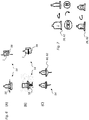
- FIGS. 1 to 3 each illustrate partial aspects of known container handling devices.
- the containers 1, for example, delivered from the labeling device (not shown) are individually conveyed via a rotating conveying and / or transfer device 2, such as a rotary star 3 (FIG. Fig. 1A , above) or a screw conveyor 4 (FIG. Fig. 1B , below) transferred to a conveyor belt 5 and in the transport direction TR for further processing device (not shown), in particular to a packaging machine, onward.
- a rotating conveying and / or transfer device 2 such as a rotary star 3 (FIG. Fig. 1A , above) or a screw conveyor 4 (FIG. Fig. 1B , below) transferred to a conveyor belt 5 and in the transport direction TR for further processing device (not
- the containers 1 are dammed up in the region of the conveyor belt 5 and conveyed in the mass flow M to the packaging machine, not shown here.
- the containers 1 are correspondingly Fig. 2 divided by means arranged perpendicular to the transport plane separating elements 6 in separate lanes 7 and then separated and divided into groups of containers 8 to form the desired packaging units in the subsequent packaging device can.
- the lanes 7 may possibly funnel-shaped or be arranged at an angle to each other.
- One possibility for the formation of container groups 8 or 9 containers is exemplified in Fig. 3 shown.
- the transported within a lane 7 in series in the transport direction TR container 1 ( Fig. 3A ) are separated by means of a grouping device 10 (FIG. Fig. 3B ) divided into the desired units ( Fig. 3C ) and then with the aid of gripping means 11 ( Fig. 3D ) to the subsequent packaging device (not shown).
- the order of the container from the mass flow out requires a relatively complex container and / or container handling, which can easily cause errors or malfunctions.
- the transport of the container itself is relatively susceptible to interference.
- a method for automatically sorting objects is known.
- the objects are given in a steady flow in a random order Zu slaughterband and promoted to a grouping device.
- a recognition device detects the position and position of the incoming objects on the feed belt and reports this data to a belt speed-taking control unit for a handling device, which sorts the objects into a grouped order state.
- the objects are grouped on the feed belt and conveyed further, the control unit evaluating the random order state on the feed belt and determining the position of a group on the feed belt.
- the DE 10 2004 048 515 A1 describes a sorting device and a conveyor for piece goods such as bottles and a method for conveying or sorting of such cargo.
- the cargo is picked up, held and transported to delivery points.
- the holding devices are arranged at individual transport units, which can be controlled individually from a receiving location to a selectable delivery point.
- the WO 2009/153080 A1 further discloses a method and apparatus for the orderly assembly of articles wherein loose, ungrouped articles having at least one infeed band are fed to at least one grouping device.
- the grouping device places the articles on an outlet conveyor in succession in a plurality of containerless groups.
- containerless grouped articles are fed to a packaging device via the outlet conveyor.
- a primary object of the invention is to propose an improved, more effective and more reliable container handling and transport, which allows containers as quickly as possible and trouble-free from a first To transport processing device to another processing and / or handling device.
- the proposed system should be as flexible as possible and, if possible, allow individually configured article compilations and / or packages and / or pallet layers or the like to be produced.
- branches can be provided, which thus create a larger network of interconnected trajectories.
- the shuttle system or the at least one transport module thus comprises a plurality of each autonomous or semi-autonomous, track-based or track-independent shuttles or Transport units, wherein the shuttles or transport units in one embodiment, for example. Above, hung laterally or down and / or can be performed on a track system or a track surface.
- Magnetic shuttles as transport units offers the advantage that each of these shuttle or each of these transport units can be controlled individually and can pass each bottle in a separate alley. In this way, a speed reduction can be ensured. The individual empty shuttle or transport units are then fed back into the return cycle, parked or otherwise controlled.
- At least the first container treatment and / or container handling module and the immediately following transport module and / or the second container treatment and / or container handling module are combined in a structural unit, which in particular a blocking may be meant. That is, the successive modules may be interlocked with each other such that no intervening transport sections are required to bridge distances between successive handling or handling stations.
- containers with different containers / types can be processed and assembled with one packing module.
- the branching point arranged in the region of the at least one transport module for the controlled steering and / or splitting of the product and / or container stream into two or more separate second, third, etc. container treatment and / or container handling modules can also be prepared.
- the second, third, fourth, etc., container handling and / or container handling modules may also each have different functions, such that, for example, one of these modules may provide for packaging while another module for palletizing and / or stacking containers and / or Containers can be equipped. In this way, an extremely flexible transport and handling machine is provided, which can fulfill in a variety of configurations satisfactorily the tasks placed on them handling, handling and / or packaging of containers.
- distribution points can be cascaded or staggered one or more times, whereby multiple distributions into any number of individual streams can take place from a single container stream.
- the labeling module is followed by a star distributor. It is a Hauptausgangsstern, which receives the container coming from the labeling and alternately emits to two downstream distribution star, so that a division of the container takes place on two flow rates. By means of distributor weirs the flow rates are then further increased to three each, i. divided into six separate lanes.
- the container streams which are now divided into six lanes, can be combined to form container groups by means of suitable grouping devices and assembled on a conveyor belt into desired containers.
- the at least one transport module comprises a conveyor chain and / or conveyor rail in which at least one further transport path branches off from a transport path.
- This conveyor chain can optionally interact with several movable transport units, individually or in groups can be coupled to the conveyor chain or decoupled from this.
- the containers can be taken directly from a previous station of the machine with a suitably prepared conveyor chain, so that they can then undergo different treatments.
- a star or so-called distribution upper transfer star may also be connected between the machine outlet and the chain.
- the chain can be embodied in different configurations, for example as a fan chain, as a chain with an attachment for a so-called neck ring handling, with gripping elements for fixing the containers to the container body, with magnetic shuttles, etc.
- the containers can various dating, inspection units, Ausscheidesysteme, etc. go through and are then passed in the connection of the chain targeted into individual lanes. This can be done by the special contour of the chain, so that the transfer can be tangential, or by ejectors that push or pull the container in the required lanes.
- the bottles can continue to be pushed over guide rails on the ground.
- the magnetic shuttle take the bottles or containers from a chain, a gripper star, from neck ring handling devices or similar facilities and grab the bottles or containers from below.
- a positive or non-positive connection between shuttle and container is made, which, for example. can be executed with a three-point clamping.
- This clamping is preferably adjustable to different container sizes, shapes and diameters.
- the fixation of the container can optionally be solved or activated by means of a lever between the bottom piece and clamping, so for example. With an actuating plunger, so that usually no conversion effort in a product change or in the handling and transport of different container sizes is required.
- the transfer of the bottles or containers can preferably be carried out again in a transport device for further processing of the container.
- these may be so-called neck-ring strips in which the bottles or containers are transferred with the magnetic shuttle and subsequently run into the grouping in a packing module such as a so-called disposable packer in neck-ring handling.
- a common feature of all the variants mentioned is that the motion or trajectories are given in a sense that a central Control of the transport units or shuttle for their individual movement or web guide along the predetermined paths can provide, without thereby an individual control of the individual transport units or shuttle is hindered.
- Each one pick-and-place system is responsible for several parallel lanes.
- individual containers or pre-grouped container units are removed from the delivery streams and deposited on a conveyor belt in a suitable position and put together to form packages, which are then packed in the packing module accordingly.
- the pick-and-place system is also capable of placing at least one container on a conveyor and feeding it to the second container treatment and / or container handling module and / or the at least one packaging module.
- individual containers or pre-grouped container units are removed from the conveyor streams and placed on a conveyor belt in a suitable position and put together to form packages, which are then packed in the packing module accordingly.
- the present invention also includes a method according to claim 5.
- the product or container stream formed by the transport units with the containers transported by these can be controlled and / or split at least at one branch point within the at least one transport module.
- the containers in the second container treatment and / or container handling module and / or the at least one packing module are separated from the transport units by means of a pick-and-place system and transferred to a downstream handling and / or packing station.
- the product or container stream may be directed and / or split within at least one transport module at least at one branch point.
- the product or container stream is moved by means of at least one conveyor chain and / or conveyor rail, wherein at least one further transport path branches off from a transport path.
- the conveyor chain cooperates with a plurality of movable transport units, which can be coupled individually or in groups with the conveyor chain or decoupled from this.
- the modules are preferably structurally combined.
- the labeling module and the packing module can be combined to form a structural unit, which may in particular mean blocking of the modules.
- a variant embodiment may provide a packing module, which is prepared for the combination of groups, containers and / or pallet layers of the same or different containers and / or containers and / or containers, each with different containers or varieties.
- an outlet or transfer star can be connected to the labeling module or to the labeling modules for transporting and conveying the containers or containers. From this outlet or transfer star can optionally be divided into two or three stars coupled with it, in order to divide the article or Gebinde stream simply or multiply in this way.
- the outlet or transfer stars or directly to the labeling a responsible for the transport of containers so-called.
- Shuttle system connect which can be formed by a variety of variants of autonomous, semi-autonomous, track-based or track-independent. Shuttles, optionally above are hung on tracks or on suitable rail documents be able to walk.
- a shuttle system is understood to be an arrangement of a plurality of transport modules which are movable independently of one another and each of which can convey one or more containers or one or more containers at the same time between the labeling module and the packing module.
- the transport and the motion control of this shuttle can be done either mechanically, eg. With conveyor chains, electric motor or by means of magnetic drives.
- such a shuttle system can replace further handling devices, since such shuttle systems can transport their transported goods directly to the packing machine.
- a shuttle system according to the invention can completely replace a so-called pick-and-place system, since the shuttle units can travel to the packing machine.
- the shuttle system is arranged between the labeling module and the packaging module essentially without further handling devices or is blocked with these modules.
- the transport system can, for example, be driven by a driving chain. But it is also conceivable and can be very advantageous that / if each system has its own drive.
- the use of linear motors, currentless power transmission or other known drives is possible.
- the transport system can also be moved via a connection of the individual transport systems, for example by pulling or pushing.
- the division into several rows can be done by a switch, eg. Via a rail, a so-called. Pusher o. The like., But also via an individual steering system.
- the division can also be done on its own drive.
- the transport system may be a platform with a plurality of so-called. Shuttle on which the container can be placed. If necessary, the container can be fixed positively or non-positively. Also, the suction or the magnetic fixing in magnetic containers is conceivable. According to an alternative embodiment, the transport system accesses the containers. This is conceivable from below, from the side, but also from above. Thus, the transport system, for example, as a packing tulip hanging, driving, or run as a sideways moving gripper.
- the shuttles can thus be moved and / or guided by means of track systems of all kinds, but optionally also by means of linear motors or magnetic drives or the like.
- the shuttles may have a plurality of runners which allow a magnetic drive in cooperation with coils or stators on the guides.
- the transport system can also at least partially take over the tasks of the packing module, e.g.
- the packing tulips can perform a vertical stroke and thus containers can be used in containers. It is also conceivable that the containers are set to a predefined position in the packing module.
- the emptied transport units are returned to the labeling module after the packing module, so that a cycle is created.
- the railing guidance of the separating elements for dividing the container from a mass flow in streets and the necessary in a product change readjustment of the separating elements can be replaced. Damage to the containers can be avoided. In addition, unfilled lanes can be avoided and downtimes reduced. The noise level can be significantly reduced, especially in glass bottles, since there is no transport of the bottles in the mass flow, in which they touch each other on all sides, permanently collide and thereby not only scratch, but also produce high noise levels.
- the route control opens up new commission options. The gripping of the individual containers also prevents the containers from falling over and resulting disturbances.
- the invention can be used as a transport system of containers.
- the transport system can perform tasks such as forming, aligning, blending and packing, which are otherwise performed by their own machines.
- the containers coming out of the labeling module are thus distributed directly to transport streams.
- no damming of the containers to a disordered mass flow takes place after the labeling module.
- the containers are split directly into at least two lanes.
- a diverter provides pre-formation of the containers by e.g. for a 6-pack formation always two containers successively divided into the respective lane and then alternately filled the next alley again with two containers.
- the transport of the containers can be dammed, for example, so that the generation of a distance between the containers or on a shuttle is possible.
- the lined containers can now be placed in a desired formation via pick-and-place systems or used directly in containers.
- the power to translate the container formations onto the conveyor belt or the shuttle system may include, but is not limited to: be increased by a juxtaposition of successive pick-and-place systems.
- the system always ensures an even gas filling due to the controlled distribution.
- the pick-and-place system can detect the containers individually or in groups.
- the groups can be designed so that a plurality of containers of the formation are arranged in one direction or that already the complete formation is formed.
- the tool required for this purpose for example gripping devices for the containers, may additionally comprise mobile units, in order, e.g. to achieve the exact container spacing for the desired container or to rotate the containers, e.g. to show the labels to the outside, if desired.
- the pick-place system is designed to be movable in the running direction of the containers, in particular by synchronizing the pick-and-place system to container speed, the translation without stopper can be facilitated and a continuous container flow without stopping (so-called stop and go) can be achieved ,
- the invention can be used as a transport system for conveying, distributing, steering and order picking of containers.
- the transport system can handle tasks such as forming, aligning, blending, and packing, which are otherwise performed by your own machines.
- the system can therefore be used in particular for dividing containers coming from a labeling module or another container handling or processing machine into containers multiple lanes and the formatting of the containers are used for subsequent processing by a packing module.
- the containers are transferred directly after the labeling module, for example, to an individual transport system.
- the orderly transport of the containers can be maintained with the invention, wherein the buffer must be dispensed with by the mass flow.
- the individual transport system always takes up a container or even a larger specific number of containers.
- This transport system has the advantage that it is guided and can create directly over switches and one-piece specific formations for the subsequently arranged packing module.
- the containers themselves have no or only limited contact with each other, whereby damage and / or noise can be avoided.
- a single-lane baying of the container can be found directly after the labeling. This can, for example, be divided over points and thus already provides a first direction of the formation. Through a one-piece, the second direction of the formation can be created. If several containers are placed on a system, a division can also be made directly after the labeling module. The formation can now be packed or packed by the packing module.
- the containers coming out of the labeling module are thus distributed directly to transport streams.
- no damming of the containers to a disordered mass flow takes place after the labeling module.
- the containers are split directly into at least two lanes.
- this is done, for example, by so-called star distributors, by distribution points or the like.
- Star distributors largely correspond to the known entry or exit stars.
- the labeled containers are removed from the labeling module via a main star.
- a first Distribution boxes are handed over the containers No. 1, 3, 5, 7 . (2n + 1).
- the remaining containers 2, 4, 6, 8 . (2n) are transferred.
- a division of the container coming out of the labeling module takes place on two lines.
- This system can also be varied at a suitable pitch; For example, a division from one to three lines is possible. It is also possible to divide up to four or more lines.
- the advantage of this system is a continuous division of the container streams, which can handle very high speeds, as dictated by the labeling module. Another combination with conventional distribution points is also possible.
- a distribution manifold already provides pre-formation of the containers by e.g. for a 6-pack formation always two containers successively divided into the respective lane and then alternately filled the next alley again with two containers.
- FIG. 4 shows a first embodiment of the direct distribution of the container 1 arriving from a container treatment module 20, such as a labeling module 22, and feeding it to a container 1 Packing module 24.
- the containers 1 transported via an outlet and / or transfer star 26 -formed, for example, by a rotary star-out of the labeling module 22 are each taken over by transport units 28, which respectively have suitable means (not shown) for gripping and holding the containers 1 respectively.
- the transport units 28 are fed to the packing module 24 via a transport device 30, for example a rail system 32, in the transport direction TR.
- the transport device 30 can optionally be divided via switches 34 and / or one-piece 36 into a plurality of transport lines 30a, 30b, 30c, so that directly specific formations of containers 1 for the packing module 24 can be created.
- the different transport lines or devices 30a, 30b, 30c, etc. may also serve to supply different packing or packaging modules 24 with containers 1, respectively.
- the division into a plurality of transport lines 30a, 30b, 30c can preferably via rails, so-called. Pusher, an individual steering system or similar. respectively. In this case, it is possible for the classification to be passively controlled or to take place by respective dedicated drives (not shown).
- the arrangement of containers 1, for example, over at least one switch 34 can be divided. By one-piece 36 a certain number of containers 1 (here four containers 1) is separated. If several containers 1 are placed on a system, a division of the containers 1 (not shown) can also take place directly after the labeling module 22, after which the formed formation can be packed or packed by the packing module 24.
- the transport system 30 can also assume the tasks of the packing module 24, for example by using suitable gripping means 38 such as packing tulips 40 (cf. Fig. 5 ) o. The like. Can perform a vertical stroke and thus container 1 can be used in containers. It is also conceivable that the containers 1 are used on a predefined position in the packing module 24. The emptied transport units 28 are returned to the container treatment module 20 or labeling module 22 after removal of the container 1 in the packaging module 24, so that a cycle is created.
- suitable gripping means 38 such as packing tulips 40 (cf. Fig. 5 ) o. The like.
- suitable gripping means 38 such as packing tulips 40 (cf. Fig. 5 ) o.
- the emptied transport units 28 are returned to the container treatment module 20 or labeling module 22 after removal of the container 1 in the packaging
- the transport system 30 By means of the transport system 30 it is avoided that the containers 1 are transported further in a mass flow M and have to be separated again into lanes 4 for the packaging (cf. Fig. 1 ). This eliminates the disturbance-prone railing or lane guidance. Furthermore, a readjustment can be omitted in a product change and damage to the containers can be avoided.
- the route control opens up new commission possibilities (cf. FIGS. 10 and 11 ). The individual gripping of the individual container 1 prevents the container 1 from falling over and resulting disturbances.
- FIG. 5 shows an embodiment of a transport device 30 with transport units 28 for the container 1, wherein the transport units 28 each have gripping elements 38, for example.
- the transport system 30 may be equipped, for example, with hanging or laterally moving grippers 38.
- the containers 1 can be gripped from below, from the side, but also from above, wherein these alternative variants can also be combined with one another in a system.
- the gripping elements 38, 40 may in particular form a so-called shuttle system, which may be formed by the transport device 30 and a plurality of transport units 28 or shuttle, which are interacting therewith or moveable therein, for a respective container 1 or more containers 1.
- the trained as a shuttle system transport device 30 makes it possible to make a pre-selection and summary of a defined number of articles or containers 1 and perform.
- Via an outlet star 26 individually to a conveyor unit - this may for example be a conveyor belt 42 - passed and directly from the gripping elements 38 and 40, respectively, to a driver system 44 are arranged, taken.
- the distance between the gripper element 38, 40 and the driver system 44 is preferably adjustable in length variable.
- each gripper element 38, 40 is preferably an actuating element 46, for example., A rail 48 (see. Fig. 5B ), assigned to support the length adjustment.
- the articles or containers 1 are conveyed by means of the gripping elements 38, 40 in the transport direction TR and, for example, deposited together in a prepared box 50, on a platform, etc. in the desired number.
- This article or container assembly in such a box 50 may also form a container 52 or be referred to as a container 52.
- container 52 may also form a container 52 or be referred to as a container 52.
- Shrink wrap or strapping are conceivable, for example.
- FIG. 6 show further embodiments of holding elements 54, which may be associated with the transport units 28 and shuttles, respectively, and which serve to fix and hold the articles of the containers 1 to the respective transport unit 28. That's how it shows Fig. 6A a laterally engaging gripping element 56.
- the Fig. 6B shows two possibilities for the positive or non-positive retention of magnetic containers 1 * by means of a magnetic holder 58 by suction or magnetic fixing, while Fig. 6C a platform 60, a so-called.
- Shuttle 62 illustrates, on which the container to be transported 1 are arranged and then For example, on a rail system or similar. (not shown) can be moved individually.
- FIG. 7 clarify that by the rotation of the individual transport units 28, in particular the individual gripping elements (not shown) or shuttles 62, an orientation of the container 1 can take place. This is particularly advantageous if the containers 1 have no round base and thus for the subsequent packaging o.ä. a defined orientation is required.
- the rotation of the individual transport units 28 can also be used to align a label located on the container envelope surfaces.
- FIGS. 8A to C show various views of another embodiment of a transport system or a transport device 30, in which the containers 1 are driven by a drive chain 64 and transported in the transport direction TR.
- the container 1 or the like via an outlet and / or transfer star 26 or rotary star from a labeling module. (Not shown) transported and moved on the carrier chain 64 in the transport direction TR individually.
- FIG. 9 is a part of a transport system indicated that can be selectively moved via a connection of the individual transport systems by train or pressure.
- the lower diagram shows a variably separable driver chain 64, on whose members individual shuttles can be anchored, so that they are moved in the transport direction TR.
- FIGS. 10 and 11 illustrate the creation of mixed containers 66, mixed pallets 68 or so-called rainbow pallets 70 etc.
- the various products 1A, 1B, 1C can be mixed by the packing machine 24 in the desired composition.
- FIG. 12 shows a transport module or a transport device 30, the / a driver or conveyor chain 64 with it can be coupled or decoupled from movable transport units (not shown here) or with the conveyor chain 64 individually transported containers 1 includes.
- several transport lanes 72 open tangentially to the conveyor chain 64, so that from there by means of a suitable slide device 74, a so-called pushers, the different containers 1 can be transferred as needed in the different transport lanes 72.
- a suitable optical detection device 76 can be determined beforehand which containers are to be pushed into which lanes 72.
- a so-called intermediate star 78 can be arranged in the region of the conveyor chain 64 for reducing the pitch of the inlet star 26, for example in order to be able to adapt the transport module 30 to an existing machine.
- the schematic view of Fig. 13 shows a further variant of a transport module 30, in which movement paths 80 for separate transport units 28 are each equipped with magnetic drives.
- the transport module 30 has separate, independently movable and controllable transport units 28 for one or more containers 1 and trajectories 80 for these transport units 28, which branch at one point or at several points.
- the trajectories 80 for the separate transport units 28 may each be provided with magnetic or electromagnetic drives, wherein the trajectories 80 may be formed in particular as long stators of linear motor sections.
- so-called magnetic shuttles 62 offers the advantage that each shuttle 62 can be controlled individually and each bottle 1 can be transferred to a separate lane of the movement path 80. In this way, a speed reduction can be ensured. The individual empty shuttle 62 are then fed back into the return cycle.
- FIG. 14 shows a side view of a portion of the transport module 30 according to Fig. 13 ,
- the magnetic shuttle 62 take over the bottles or containers 1 from a chain, a gripper star, from neck ring handling devices or similar devices, and grip the bottles or containers 1 from below.
- a positive or non-positive connection between the shuttle 62 and container 1 is produced, which can be performed, for example, with a three-point clamping 82.
- This clamp 82 is preferably variably adjustable to different container sizes, shapes and diameters.
- the fixation of the container 1 can optionally be solved or activated by means of a lever between the bottom piece and clamping, so for example.
- the transfer of the bottles or containers 1 can preferably be carried out again in a transport device for further processing of the container 1.
- these may be so-called neckring strips, in which the bottles or containers are transferred with the magnetic shuttle 62 and then run into the grouping in a packing module such as a so-called disposable packer in neckring handling.
- a packing module such as a so-called disposable packer in neckring handling.
- the motion or trajectory is predetermined and the Shuttle 62 can be individually controlled.
- FIGS. 15 and 16 illustrate a further embodiment of a direct distribution of coming from a labeling module 22 container 1 and the supply thereof to a packing module 24.
- This container double stream is then separated by distribution points 34 in a total of six transport streams.
- the star distributor 86 is in Fig. 13 shown in detail and consists in the illustrated embodiment of three transport stars 87, 88, and 89.
- container 1 In the main star 87 coming from the labeling module 22 container 1 are transported.
- the first distributor star 88 for example, the containers 1 No. 1, No. 3, No. 5, No. 7 ... No. (2n + 1) .. are transferred.
- the second distributor star 89 Upon contact with the second distributor star 89, the remaining containers 1 no. 2, no. 4, no. 6, no. 8 ... no. (2n) are handed over.
- a division into the two transport lines 30 The system can be varied even with a suitable other division, so that, for example, a division into three or more transport lines can be done.
- a further division of the double stream described on a total of four transport lines is possible.
- the advantage of this system is a continuous division that can handle very high speeds, such as those found in known labeling modules 24.
- the distribution points 34 can provide a pre-formation of the container 1 by, for example, for a six-pack formation always two containers 1 successively divided into the respective lane 90 and then alternately filled the next lane with two containers.
- the container double packs 92 can then be transferred to a conveyor belt and thereby assembled via pick and place systems 94 directly to the packs 52 to be packaged and transported to the packing module 24.
- the performance for translating the container formations, for example the container double pack 92 onto the conveyor belt or another shuttle system can be achieved, inter alia, by a series be increased by pick and place systems 94.
- a pick-and-place system 94 is therefore in particular a system which has means for gripping, holding and displacing at least one container 1 or a plurality of containers 1.
- the pick-and-place system 94 can detect the containers 1 individually or in groups 92.
- the groups 92 may be formed as follows: a plurality of containers 1 of the formation in one direction or the complete formation, i. a complete container 52.
- the tool required for this purpose on the one hand means grasping and holding means and means for moving the container 1 and may additionally have movable units to achieve, for example, the exact container spacing for the container to be created or the container too turn, for example, to let the labels face outward, so that a recognition of the product is facilitated.
- the system is used for splitting the containers 1 from the labeling module 22 into a plurality of transport lines 30 and then formatting the containers 1 for the packing module 24.
- the transport of the container 1 can, for example, be deliberately dammed up, in particular in order to achieve adaptation to the processing speed by the packing module 24. Furthermore, it is possible to set a defined distance between the containers 1.
- the containers 1 are, for example, in the transport lines 30 through the already in Fig. 4 described by transport units (not shown), for example by gripper 38, magnetic brackets 58, platforms 60, shuttles 62 or similar. (see. Fig. 6 ).
- the orderly promotion of the container 1 can be done with this embodiment, a picking of products.
- the controlled distribution of the container 1, the system always ensures a uniform gas filling and feeding containers to the packing module 24th
Landscapes
- Engineering & Computer Science (AREA)
- Mechanical Engineering (AREA)
- Specific Conveyance Elements (AREA)
- Attitude Control For Articles On Conveyors (AREA)
- Warehouses Or Storage Devices (AREA)
- Labeling Devices (AREA)
Description
Die vorliegende Erfindung betrifft eine Anordnung mehrerer miteinander gekoppelter und in unmittelbar aufeinander folgender Behandlungsabfolge stehender Behälterhandhabungs- und/oder Behälterbehandlungs- und/oder Behältertransportmodule mit den Merkmalen des Oberbegriffs des unabhängigen Anspruchs 1. Die Erfindung betrifft weiterhin ein Verfahren zum Transport, zur Behandlung und/oder Handhabung von Behältern mit den Merkmalen des Oberbegriffs des unabhängigen Verfahrensanspruchs 5.The present invention relates to an arrangement of a plurality of container handling and / or container treatment and / or container transport modules coupled to one another and arranged in a directly successive treatment sequence, having the features of the preamble of
Bei der Zusammenfassung und Verpackung von einzelnen Behältern, bspw. von befüllten Flaschen, werden diese normalerweise nacheinander aus einer Verarbeitungsmaschine geliefert, bspw. aus eine Abfüllanlage oder einer Etikettiervorrichtung, um sie in nachfolgenden Verarbeitungsstufen weiter zu behandeln und/oder zu Gebinden zusammenzufassen und/oder anderweitig zu verpacken. Zum Zusammenstellen und Verpacken mehrerer Behälter in einem Gebinde wird die Zuführung der Behälter zur Verpackungsmaschine im Massenstrom bevorzugt.When combining and packaging individual containers, for example of filled bottles, they are normally delivered one after the other from a processing machine, for example from a filling line or a labeling device, in order to further treat and / or package them in subsequent processing stages and / or otherwise pack. For assembling and packaging a plurality of containers in a container, the supply of the container to the packaging machine in a mass flow is preferred.
Der Behältertransport zwischen einer Behälterbehandlungsmaschine wie bspw. einer Etikettiermaschine und einer nachgeordneten Verpackungsmaschine kann bspw. entsprechend der
Das Ordnen der Gebinde aus dem Massenstrom heraus erfordert ein relativ aufwändiges Behälter- und/oder Gebindehandling, woraus leicht Fehler oder Störungen entstehen können. Auch der Transport der Behälter an sich ist relativ störanfällig.The order of the container from the mass flow out requires a relatively complex container and / or container handling, which can easily cause errors or malfunctions. The transport of the container itself is relatively susceptible to interference.
Aus der
Aus der
Die
Die
Ein vorrangiges Ziel der Erfindung wird darin gesehen, eine verbesserte, effektivere und zuverlässigere Behälterbehandlung und -beförderung vorzuschlagen, die es erlaubt, Behälter möglichst schnell und dabei störungsfrei von einer ersten Bearbeitungsvorrichtung zu einer weiteren Bearbeitungs- und/oder Handhabungsvorrichtung zu transportieren. Das vorgeschlagene System soll möglichst flexibel sein und es nach Möglichkeit erlauben, individuell konfigurierte Artikelzusammenstellungen und/oder Gebinde und/oder Palettenlagen o. dgl. zu erzeugen.A primary object of the invention is to propose an improved, more effective and more reliable container handling and transport, which allows containers as quickly as possible and trouble-free from a first To transport processing device to another processing and / or handling device. The proposed system should be as flexible as possible and, if possible, allow individually configured article compilations and / or packages and / or pallet layers or the like to be produced.
Diese Ziele der Erfindung werden mit den Gegenständen der unabhängigen Ansprüche 1 und 5 erreicht. Merkmale vorteilhafter Weiterbildungen der Erfindung ergeben sich aus den jeweiligen abhängigen Ansprüchen. So schlägt die vorliegende Erfindung zur Erreichung der Ziele der Erfindung eine Anordnung nach dem Anspruch 1.These objects of the invention are achieved with the subject-matter of
Wahlweise können auch mehrere Verzweigungen vorgesehen sein, die damit ein größeres Netz von miteinander verbundenen Bewegungsbahnen entstehen lassen.Optionally, several branches can be provided, which thus create a larger network of interconnected trajectories.
Wenn im vorliegenden Zusammenhang von einem Transportmodul mit mehreren separat voneinander beweglichen und jeweils an Bewegungsbahnen gebundene Transporteinheiten sowie von einem Shuttle-System die Rede ist, so sind diese Begriffe synonym zu verstehen, da sie jeweils dasselbe meinen. Das Shuttle-System bzw. das wenigstens eine Transportmodul umfasst somit eine Mehrzahl von jeweils autonomen oder teilautonomen, gleisgestützten oder gleisunabhängigen Shuttles oder Transporteinheiten, wobei die Shuttles oder Transporteinheiten in einer Ausführungsvariante bspw. oben, seitlich oder unten aufgehängt und/oder auf einem Gleissystem bzw. einer Gleisunterlage geführt sein können.If in the present context of a transport module with several separately movable and each bound to trajectories transport units and a shuttle system is mentioned, these terms are synonymous to understand, since they mean the same thing. The shuttle system or the at least one transport module thus comprises a plurality of each autonomous or semi-autonomous, track-based or track-independent shuttles or Transport units, wherein the shuttles or transport units in one embodiment, for example. Above, hung laterally or down and / or can be performed on a track system or a track surface.
Speziell eine Ausführungsvariante mit sog. Magnet-Shuttlen als Transporteinheiten bietet den Vorteil, dass jedes dieser Shuttle bzw. jede dieser Transporteinheiten individuell angesteuert werden kann und jede Flasche in eine separate Gasse übergeben kann. Auf diese Weise kann auch ein Geschwindigkeitsabbau gewährleistet werden. Die einzelnen leeren Shuttle oder Transporteinheiten werden dann wieder in den Rück-Kreislauf eingespeist, zwischengeparkt oder anderweitig gesteuert.Specifically, a variant with so-called. Magnetic shuttles as transport units offers the advantage that each of these shuttle or each of these transport units can be controlled individually and can pass each bottle in a separate alley. In this way, a speed reduction can be ensured. The individual empty shuttle or transport units are then fed back into the return cycle, parked or otherwise controlled.
Gemäß einer bevorzugten Ausführungsvariante der erfindungsgemäßen Anordnung sind zumindest das erste Behälterbehandlungs- und/oder Behälterhandhabungsmodul und das diesem unmittelbar nachgeordnete Transportmodul und/oder das zweite Behälterbehandlungs- und/oder Behälterhandhabungsmodul in einer baulichen Einheit zusammengefasst, womit insbesondere eine Verblockung gemeint sein kann. D.h., die aufeinander folgenden Module können derart miteinander verblockt sein, dass keine dazwischen angeordneten Transportabschnitte zur Überbrückung von Distanzen zwischen aufeinander folgenden Behandlungs- oder Handhabungsstationen erforderlich sind.According to a preferred embodiment of the arrangement according to the invention, at least the first container treatment and / or container handling module and the immediately following transport module and / or the second container treatment and / or container handling module are combined in a structural unit, which in particular a blocking may be meant. That is, the successive modules may be interlocked with each other such that no intervening transport sections are required to bridge distances between successive handling or handling stations.
Bei Bedarf können mit einem Packmodul auch Gebinde mit jeweils unterschiedlichen Behältern/Sorten verarbeitet und zusammengestellt werden.If required, containers with different containers / types can be processed and assembled with one packing module.
Wahlweise kann auch die im Bereich des wenigstens einen Transportmoduls angeordnete Verzweigungsstelle zur gesteuerten Lenkung und/oder Aufteilung des Produkt- und/oder Behälterstroms zu zwei oder mehr separaten zweiten, dritten etc. Behälterbehandlungs- und/oder Behälterhandhabungsmodulen vorbereitet sein. Die zweiten, dritten, vierten etc. Behälterbehandlungs- und/oder Behälterhandhabungsmodule können auch jeweils unterschiedliche Funktionen aufweisen, so dass bspw. eines dieser Module für die Verpackung sorgen kann, während ein weiteres Modul für das Palettieren und/oder Stapeln von Behältern und/oder Gebinden ausgestattet sein kann. Auf diese Weise wird eine äußerst flexible Transport- und Handhabungsmaschine zur Verfügung gestellt, welche in den unterschiedlichsten Konfigurationen die an sie gestellten Aufgaben der Handhabung, Behandlung und/oder Verpackung von Behältern in zufriedenstellender Weise erfüllen kann.Optionally, the branching point arranged in the region of the at least one transport module for the controlled steering and / or splitting of the product and / or container stream into two or more separate second, third, etc. container treatment and / or container handling modules can also be prepared. The second, third, fourth, etc., container handling and / or container handling modules may also each have different functions, such that, for example, one of these modules may provide for packaging while another module for palletizing and / or stacking containers and / or Containers can be equipped. In this way, an extremely flexible transport and handling machine is provided, which can fulfill in a variety of configurations satisfactorily the tasks placed on them handling, handling and / or packaging of containers.
Verteilweichen können ggf. einfach oder mehrfach kaskadiert bzw. gestaffelt angeordnet sein, wodurch aus einem einzelnen Behälterstrom eine mehrfache Aufteilung in eine beliebige Anzahl von Einzelströmen erfolgen kann.If necessary, distribution points can be cascaded or staggered one or more times, whereby multiple distributions into any number of individual streams can take place from a single container stream.
Wahlweise ist dem Etikettiermodul ein Sternverteiler nachgeordnet. Dabei handelt es sich um einen Hauptausgangsstern, der die aus dem Etikettiermodul kommenden Behälter aufnimmt und abwechselnd an zwei nachgeordnete Verteilersterne abgibt, so dass eine Aufteilung der Behälter auf zwei Förderströme erfolgt. Mittels Verteilerweichen werden die Förderströme anschließend weiter auf jeweils drei, d.h. insgesamt sechs separate Gassen aufgeteilt. Die in nunmehr sechs Gassen aufgeteilten Behälterströme können mittels geeigneten Gruppiereinrichtungen zu Behältergruppen zusammengefasst und auf einem Förderband zu gewünschten Gebinden zusammengestellt werden.Optionally, the labeling module is followed by a star distributor. It is a Hauptausgangsstern, which receives the container coming from the labeling and alternately emits to two downstream distribution star, so that a division of the container takes place on two flow rates. By means of distributor weirs the flow rates are then further increased to three each, i. divided into six separate lanes. The container streams, which are now divided into six lanes, can be combined to form container groups by means of suitable grouping devices and assembled on a conveyor belt into desired containers.
Eine weitere alternative oder ergänzende Ausführungsvariante der erfindungsgemäßen Anordnung sieht vor, dass das wenigstens eine Transportmodul eine Förderkette und/oder Förderschiene umfasst, bei der von einem Transportweg wenigstens ein weiterer Transportweg abzweigt. Diese Förderkette kann wahlweise mit mehreren beweglichen Transporteinheiten zusammenwirken, die einzeln oder in Gruppen mit der Förderkette koppelbar oder von dieser entkoppelbar sind. So können die Behälter direkt aus einer vorherigen Station der Maschine mit einer entsprechend vorbereiteten Förderkette übernommen werden, so dass sie im Anschluss unterschiedliche Behandlungen durchlaufen können. Je nach Geschwindigkeit, Teilung, etc. kann zwischen Maschinenauslauf und Kette auch ein Stern bzw. sog. Verteil- ober Übergabestern geschaltet sein. Die Kette kann je nach Behälterart in unterschiedlichen Ausgestaltungen ausgeführt sein, bspw. als Fächerkette, als Kette mit Aufsatz für ein sog. Neckringhandling, mit Greifelementen zum Fixieren der Behälter jeweils an deren Behälterrumpf, mit Magnet-Shuttlen etc. Nach der Aufnahme der Flaschen oder Behälter in der Kette können die Behälter diverse Datierungen, Inspektionseinheiten, Ausscheidesysteme, etc. durchlaufen und werden dann im Anschluss von der Kette gezielt in einzelne Gassen übergeben. Dies kann durch die spezielle Kontur der Kette erfolgen, so dass die Übergabe tangential erfolgen kann, oder auch durch Ausstoßeinrichtungen, welche die Behälter in die benötigten Gassen schieben oder ziehen. Um nicht das komplette Gewicht des gefüllten Behälters in die Kette zu übernehmen, können die Flaschen weiterhin über Führungsleisten am Boden geschoben werden.A further alternative or supplementary embodiment variant of the arrangement according to the invention provides that the at least one transport module comprises a conveyor chain and / or conveyor rail in which at least one further transport path branches off from a transport path. This conveyor chain can optionally interact with several movable transport units, individually or in groups can be coupled to the conveyor chain or decoupled from this. Thus, the containers can be taken directly from a previous station of the machine with a suitably prepared conveyor chain, so that they can then undergo different treatments. Depending on the speed, pitch, etc., a star or so-called distribution upper transfer star may also be connected between the machine outlet and the chain. Depending on the type of container, the chain can be embodied in different configurations, for example as a fan chain, as a chain with an attachment for a so-called neck ring handling, with gripping elements for fixing the containers to the container body, with magnetic shuttles, etc. After picking up the bottles or Containers in the chain, the containers can various dating, inspection units, Ausscheidesysteme, etc. go through and are then passed in the connection of the chain targeted into individual lanes. This can be done by the special contour of the chain, so that the transfer can be tangential, or by ejectors that push or pull the container in the required lanes. In order not to take over the full weight of the filled container in the chain, the bottles can continue to be pushed over guide rails on the ground.
Bei einer weiteren Variante der Anordnung übernehmen die Magnet-Shuttle die Flaschen oder Behälter aus einer Kette, einem Greiferstern, aus Neckring-Handling-Einrichtungen oder ähnlichen Einrichtungen und greifen die Flaschen oder Behälter jeweils von unten. Dabei wird eine form- bzw. kraftschlüssige Verbindung zwischen Shuttle und Behälter hergestellt, welche z.B. mit einer Drei-Punkt-Klemmung ausgeführt sein kann. Diese Klemmung ist vorzugsweise variabel auf unterschiedliche Behältergrößen, -formen und -durchmesser einstellbar. Die Fixierung der Behälter kann wahlweise auch mittels eines Hebel zwischen Bodenstück und Klemmung gelöst oder aktiviert werden, so bspw. mit einem Betätigungs-Stößel, so dass in der Regel kein Umrüstungsaufwand bei einem Produktwechsel oder bei der Handhabung und dem Transport unterschiedlicher Behältergrößen erforderlich ist. Die Übergabe der Flaschen oder Behälter kann vorzugsweise wieder in eine Transporteinrichtung zur weiteren Bearbeitung der Behälter erfolgen. Als Beispiel können dies sog. Neckring-Leisten sein, in denen die Flaschen oder Behälter mit dem Magnet-Shuttle übergeben werden und im Anschluss im Neckring-Handling in die Gruppierung in einem Packmodul wie bspw. einem sog. Einweg-Packer einlaufen.In a further variant of the arrangement, the magnetic shuttle take the bottles or containers from a chain, a gripper star, from neck ring handling devices or similar facilities and grab the bottles or containers from below. In this case, a positive or non-positive connection between shuttle and container is made, which, for example. can be executed with a three-point clamping. This clamping is preferably adjustable to different container sizes, shapes and diameters. The fixation of the container can optionally be solved or activated by means of a lever between the bottom piece and clamping, so for example. With an actuating plunger, so that usually no conversion effort in a product change or in the handling and transport of different container sizes is required. The transfer of the bottles or containers can preferably be carried out again in a transport device for further processing of the container. As an example, these may be so-called neck-ring strips in which the bottles or containers are transferred with the magnetic shuttle and subsequently run into the grouping in a packing module such as a so-called disposable packer in neck-ring handling.
Ein gemeinsames Merkmal aller genannten Varianten besteht darin, dass die Bewegungs- oder Verfahrbahnen in einem Sinne vorgegeben sind, dass eine zentrale Steuerung der Transporteinheiten bzw. Shuttle für deren individuelle Bewegungs- bzw. Bahnführung entlang der vorgegebenen Bahnen sorgen kann, ohne dass dadurch eine individuelle Ansteuerung der einzelnen Transporteinheiten oder Shuttle behindert ist.A common feature of all the variants mentioned is that the motion or trajectories are given in a sense that a central Control of the transport units or shuttle for their individual movement or web guide along the predetermined paths can provide, without thereby an individual control of the individual transport units or shuttle is hindered.
Jeweils ein einzelnes Pick-und-Place-System ist für mehrere parallele Gassen zuständig. Mit dem System werden bspw. einzelne Behälter oder vorgruppierte Behältereinheiten aus den Förderströmen entnommen und auf einem Förderband in einer passenden Position abgesetzt und zu Gebinden zusammen gestellt, die dann im Packmodul entsprechend verpackt werden. Das Pick-und-Place-System ist auch in der Lage, mindestens einen Behälter auf einer Fördereinrichtung zu platzieren und dem zweiten Behälterbehandlungs- und/oder Behälterhandhabungsmodul und/oder dem wenigstens einen Packmodul zuzuführen. Typischerweise werden mit dem System bspw. einzelne Behälter oder vorgruppierte Behältereinheiten aus den Förderströmen entnommen und auf einem Förderband in einer passenden Position abgesetzt und zu Gebinden zusammen gestellt, die dann im Packmodul entsprechend verpackt werden.Each one pick-and-place system is responsible for several parallel lanes. With the system, for example, individual containers or pre-grouped container units are removed from the delivery streams and deposited on a conveyor belt in a suitable position and put together to form packages, which are then packed in the packing module accordingly. The pick-and-place system is also capable of placing at least one container on a conveyor and feeding it to the second container treatment and / or container handling module and / or the at least one packaging module. Typically, with the system, for example, individual containers or pre-grouped container units are removed from the conveyor streams and placed on a conveyor belt in a suitable position and put together to form packages, which are then packed in the packing module accordingly.
Zur Erreichung des o.g. Ziels umfasst die vorliegende Erfindung auch ein Verfahren nach dem Anspruch 5.To achieve the above object, the present invention also includes a method according to
Bei einer Variante des Verfahren kann der durch die Transporteinheiten mit den von diesen transportierten Behältern gebildete Produkt- oder Behälterstrom innerhalb des wenigstens einen Transportmoduls an mindestens einer Verzweigungsstelle gesteuert gelenkt und/oder aufgeteilt werden. Zudem kann vorgesehen sein, dass die Behälter im zweiten Behälterbehandlungs- und/oder Behälterhandhabungsmodul und/oder dem wenigstens einen Packmodul mittels eines Pick-und-Place-Systems von den Transporteinheiten getrennt und an eine nachgeordnete Handhabungs- und/oder Packstation übergeben werden.In a variant of the method, the product or container stream formed by the transport units with the containers transported by these can be controlled and / or split at least at one branch point within the at least one transport module. In addition, it can be provided that the containers in the second container treatment and / or container handling module and / or the at least one packing module are separated from the transport units by means of a pick-and-place system and transferred to a downstream handling and / or packing station.
Wahlweise kann der Produkt- oder Behälterstrom innerhalb des wenigstens einen Transportmoduls an mindestens einer Verzweigungsstelle gesteuert gelenkt und/oder aufgeteilt werden. Weiterhin kann vorgesehen sein, dass der Produkt- oder Behälterstrom mittels wenigstens einer Förderkette und/oder Förderschiene bewegt wird, bei der von einem Transportweg wenigstens ein weiterer Transportweg abzweigt. Zudem kann auch vorgesehen sein, dass die Förderkette mit mehreren beweglichen Transporteinheiten zusammenwirkt, die einzeln oder in Gruppen mit der Förderkette koppelbar oder von dieser entkoppelbar sind.Optionally, the product or container stream may be directed and / or split within at least one transport module at least at one branch point. Furthermore, it can be provided that the product or container stream is moved by means of at least one conveyor chain and / or conveyor rail, wherein at least one further transport path branches off from a transport path. In addition, it can also be provided that the conveyor chain cooperates with a plurality of movable transport units, which can be coupled individually or in groups with the conveyor chain or decoupled from this.
Die Module sind vorzugsweise baulich zusammengefasst. Insbesondere können das Etikettiermodul und das Packmodul zu einer baulichen Einheit zusammengefasst sein, womit insbesondere eine Verblockung der Module gemeint sein kann. Eine Ausführungsvariante kann ein Packmodul vorsehen, welches für die Zusammenfassung von Gruppierungen, Gebinden und/oder Palettenlagen aus gleichen oder unterschiedlichen Behältern und/oder Gebinden und/oder Gebinden mit jeweils unterschiedlichen Behältern bzw. Sorten vorbereitet ist. An das Etikettiermodul bzw. an die Etikettiermodule kann sich wahlweise ein Auslauf- bzw. Übergabestern zum Transport und zur Förderung der Behälter oder Gebinde anschließen. Von diesem Auslauf- bzw. Übergabestern kann wahlweise eine Aufteilung auf zwei oder drei damit gekoppelte Sterne erfolgen, um auf diese Weise den Artikel- oder Gebindestrom einfach oder mehrfach aufzuteilen.The modules are preferably structurally combined. In particular, the labeling module and the packing module can be combined to form a structural unit, which may in particular mean blocking of the modules. A variant embodiment may provide a packing module, which is prepared for the combination of groups, containers and / or pallet layers of the same or different containers and / or containers and / or containers, each with different containers or varieties. Optionally, an outlet or transfer star can be connected to the labeling module or to the labeling modules for transporting and conveying the containers or containers. From this outlet or transfer star can optionally be divided into two or three stars coupled with it, in order to divide the article or Gebinde stream simply or multiply in this way.
Wahlweise kann sich den Auslauf- bzw. Übergabesternen oder auch unmittelbar dem Etikettiermodul ein für den Transport der Behälter verantwortliches sog. Shuttle-System anschließen, das durch unterschiedlichste Varianten von autonomen, teilautonomen, gleisgestützten oder gleisunabhängigen sog. Shuttles gebildet sein kann, die wahlweise oben an Gleisen aufgehängt sind oder auf geeigneten Schienenunterlagen laufen können. Als Shuttle-System wird in diesem Zusammenhang eine Anordnung einer Mehrzahl von unabhängig voneinander beweglichen Transportmodulen verstanden, die jeweils einen oder mehrere Behälter bzw. ein oder mehrere Gebinde gleichzeitig zwischen dem Etikettiermodul und dem Packmodul befördern können. Der Transport und die Bewegungssteuerung dieser Shuttle kann wahlweise mechanisch, bspw. mit Förderketten, elektromotorisch oder auch mittels Magnetantrieben erfolgen.Optionally, the outlet or transfer stars or directly to the labeling a responsible for the transport of containers so-called. Shuttle system connect, which can be formed by a variety of variants of autonomous, semi-autonomous, track-based or track-independent. Shuttles, optionally above are hung on tracks or on suitable rail documents be able to walk. In this context, a shuttle system is understood to be an arrangement of a plurality of transport modules which are movable independently of one another and each of which can convey one or more containers or one or more containers at the same time between the labeling module and the packing module. The transport and the motion control of this shuttle can be done either mechanically, eg. With conveyor chains, electric motor or by means of magnetic drives.
Gemäß einer vorteilhaften Ausführungsvariante kann ein solches Shuttle-System weitere Handhabungseinrichtungen ersetzen, da solche Shuttle-Systeme ihre Transportgüter bis unmittelbar zur Packmaschine befördern können. So kann ein solches erfindungsgemäßes Shuttle-System bspw. ein sog. Pick-and-Place-System komplett ersetzen, denn die Shuttle-Einheiten können bis zur Packmaschine fahren. Gemäß einer bevorzugten Ausführungsform ist das Shuttle-System im Wesentlichen ohne weitere Handhabungseinrichtungen zwischen dem Etikettiermodul und dem Packmodul angeordnet bzw. mit diesen Modulen verblockt.According to an advantageous embodiment variant, such a shuttle system can replace further handling devices, since such shuttle systems can transport their transported goods directly to the packing machine. For example, such a shuttle system according to the invention can completely replace a so-called pick-and-place system, since the shuttle units can travel to the packing machine. According to a preferred embodiment, the shuttle system is arranged between the labeling module and the packaging module essentially without further handling devices or is blocked with these modules.
Das Transportsystem kann bspw. durch eine Mitnehmerkette angetrieben werden. Es ist aber auch denkbar und kann sehr vorteilhaft sein, dass/wenn jedes System seinen eigenen Antrieb aufweist. Dabei ist die Verwendung von Linearmotoren, stromloser Energieübertragung oder anderer bekannter Antriebe möglich. Das Transportsystem kann auch über eine Verbindung der einzelnen Transportsysteme, bspw. durch Zug oder Druck, bewegt werden. Die Aufteilung in mehrere Reihen kann durch eine Weiche, bspw. über eine Schiene, einen sog. Pusher o. dgl., aber auch über ein individuelles Lenksystem erfolgen. Die Teilung kann auch über den eigenen Antrieb erfolgen.The transport system can, for example, be driven by a driving chain. But it is also conceivable and can be very advantageous that / if each system has its own drive. The use of linear motors, currentless power transmission or other known drives is possible. The transport system can also be moved via a connection of the individual transport systems, for example by pulling or pushing. The division into several rows can be done by a switch, eg. Via a rail, a so-called. Pusher o. The like., But also via an individual steering system. The division can also be done on its own drive.
Das Transportsystem kann eine Plattform mit einer Vielzahl von sog. Shuttle sein, auf die der Behälter gestellt werden können. Bei Bedarf kann der Behälter form- oder kraftschlüssig fixiert werden. Auch das Ansaugen oder das magnetische Fixieren bei magnetischen Behältern ist denkbar. Gemäß einer alternativen Ausführungsform greift das Transportsystem die Behälter. Dies ist von unten, von der Seite, aber auch von oben denkbar. Somit kann das Transportsystem z.B. als Packtulpe hängend, fahrend, oder als seitlich fahrender Greifer ausgeführt werden. Die Shuttles können somit mittels Gleissystemen aller Art, jedoch wahlweise auch mittels Linearmotoren oder Magnetantrieben o. dgl. bewegt und/oder geführt werden. So können die Shuttles bspw. mehrere Läufer aufweisen, die einen magnetischen Antrieb in Zusammenwirkung mit Spulen bzw. Statoren an den Führungen ermöglichen.The transport system may be a platform with a plurality of so-called. Shuttle on which the container can be placed. If necessary, the container can be fixed positively or non-positively. Also, the suction or the magnetic fixing in magnetic containers is conceivable. According to an alternative embodiment, the transport system accesses the containers. This is conceivable from below, from the side, but also from above. Thus, the transport system, for example, as a packing tulip hanging, driving, or run as a sideways moving gripper. The shuttles can thus be moved and / or guided by means of track systems of all kinds, but optionally also by means of linear motors or magnetic drives or the like. Thus, for example, the shuttles may have a plurality of runners which allow a magnetic drive in cooperation with coils or stators on the guides.
Durch eine Rotation der einzelnen Transportsysteme kann eine Behälterausrichtung erfolgen. Dies kann bei besonderen Behälterformen notwendig sein, weiterhin kann dadurch die Ausrichtung des Etiketts erfolgen.By a rotation of the individual transport systems can be carried out a container orientation. This may be necessary in the case of special container shapes, and furthermore the alignment of the label can take place as a result.
Durch die individuelle Führung können verschiedene Produkte gemischt werden. Es ist denkbar, dass zwei oder mehrere Transportströme bspw. aus mehreren Etikettiermodulen mit verschiedenen Behältern zusammen geführt werden, um Mischgebinde, sog. Regenbogenpaletten oder gemischte Paletten zu erstellen.Due to the individual guidance different products can be mixed. It is conceivable that two or more transport streams, for example, from several labeling modules with different containers are led together to create mixed containers, so-called. Rainbow pallets or mixed pallets.
Das Transportsystem kann auch zumindest teilweise die Aufgaben des Packmoduls übernehmen, indem z.B. die Packtulpen einen vertikalen Hub ausführen können und somit Behälter in Gebinde eingesetzt werden können. Es ist auch denkbar, dass die Behälter auf eine vordefinierte Stelle in dem Packmodul gesetzt werden.The transport system can also at least partially take over the tasks of the packing module, e.g. The packing tulips can perform a vertical stroke and thus containers can be used in containers. It is also conceivable that the containers are set to a predefined position in the packing module.
Die entleerten Transporteinheiten werden nach dem Packmodul wieder zum Etikettiermodul zurückgeführt, so dass ein Kreislauf entsteht.The emptied transport units are returned to the labeling module after the packing module, so that a cycle is created.
Durch das Transportsystem können die Geländerführung der Trennelemente zur Aufteilung der Behälter aus einem Massenstrom in Gassen und die bei einem Produktwechsel notwendige Neueinstellung der Trennelemente ersetzt werden. Beschädigungen an den Behältern können vermieden werden. Außerdem können nicht befüllte Gassen vermieden und Stillstandszeiten verringert werden. Der Lärmpegel kann vor allem bei Glasflaschen wesentlich reduziert werden, da kein Transport der Flaschen im Massenstrom erfolgt, bei dem sich diese allseitig berühren, permanent kollidieren und dabei nicht nur verkratzen, sondern auch hohe Lärmpegel erzeugen. Durch die Wegsteuerung werden neue Kommissionsmöglichkeiten eröffnet. Das Greifen der einzelnen Behälter verhindert zudem ein Umfallen der Behälter und daraus resultierende Störungen.By the transport system, the railing guidance of the separating elements for dividing the container from a mass flow in streets and the necessary in a product change readjustment of the separating elements can be replaced. Damage to the containers can be avoided. In addition, unfilled lanes can be avoided and downtimes reduced. The noise level can be significantly reduced, especially in glass bottles, since there is no transport of the bottles in the mass flow, in which they touch each other on all sides, permanently collide and thereby not only scratch, but also produce high noise levels. The route control opens up new commission options. The gripping of the individual containers also prevents the containers from falling over and resulting disturbances.
Die Erfindung kann als Transportsystem von Behältern verwendet werden. Durch das Transportsystem können Aufgaben wie Formieren, Ausrichten, Mischen und Packen übernommen werden, die sonst von eigenen Maschinen ausgeführt werden.The invention can be used as a transport system of containers. The transport system can perform tasks such as forming, aligning, blending and packing, which are otherwise performed by their own machines.
Um die durch das derzeit verwendete System verursachten Störungen zu umgehen, werden die aus dem Etikettiermodul kommenden Behälter also direkt auf Transportströme verteilt. Insbesondere erfolgt nach dem Etikettiermodul kein Aufstauen der Behälter zu einem ungeordneten Massenstrom. Stattdessen werden die Behälter direkt in mindestens zwei Gassen aufgeteilt.In order to avoid the disturbances caused by the currently used system, the containers coming out of the labeling module are thus distributed directly to transport streams. In particular, no damming of the containers to a disordered mass flow takes place after the labeling module. Instead, the containers are split directly into at least two lanes.
Eine Verteilweiche liefert eine Vor-Formation der Behälter, indem sie z.B. für eine 6er Gebinde-Formation immer zwei Behälter nacheinander in die jeweilige Gasse aufteilt und dann alternierend die nächste Gasse wieder mit zwei Behältern befüllt.A diverter provides pre-formation of the containers by e.g. for a 6-pack formation always two containers successively divided into the respective lane and then alternately filled the next alley again with two containers.
Der Transport der Behälter kann bspw. aufgestaut werden, so dass die Erzeugung eines Abstandes zwischen den Behältern oder auf einem Shuttle möglich ist. Die aufgereihten Behälter können nun über Pick-und-Place-Systeme in eine gewünschte Formation gesetzt oder unmittelbar in Gebinde eingesetzt werden. Die Leistung zum Übersetzen der Behälter- Formationen auf das Transportband oder das Shuttle System kann u.a. durch eine Aneinanderreihung von aufeinander folgenden Pick-und-Place-Systemen erhöht werden.The transport of the containers can be dammed, for example, so that the generation of a distance between the containers or on a shuttle is possible. The lined containers can now be placed in a desired formation via pick-and-place systems or used directly in containers. The power to translate the container formations onto the conveyor belt or the shuttle system may include, but is not limited to: be increased by a juxtaposition of successive pick-and-place systems.
Durch die geordnete Förderung der Behälter kann eine vorgegebene Kommissionierung erfolgen, mit der Mischgebinde, Regenbogenpaletten und nahezu beliebige andere Mischpaletten erstellt werden können.By the orderly promotion of the container, a given picking done, can be created with the mixed containers, rainbow pallets and almost any other mixed pallets.
Das System gewährleistet durch die gesteuerte Aufteilung immer eine gleichmäßige Gassenbefüllung.The system always ensures an even gas filling due to the controlled distribution.
Das Pick-und-Place-System kann die Behälter einzeln oder auch in Gruppen erfassen. Die Gruppen können so ausgebildet sein, dass mehrere Behälter der Formation in einer Richtung angeordnet sind oder dass bereits die komplette Formation gebildet wird. Das hierfür benötigte Werkzeug, bspw. Greifvorrichtungen für die Behälter, kann zusätzlich noch bewegliche Einheiten aufweisen, um z.B. den genauen Behälterabstand für das gewünschte Gebinde zu erreichen oder auch die Behälter zu drehen, um z.B. die Etiketten nach außen zeigen zu lassen, sofern dies gewünscht ist.The pick-and-place system can detect the containers individually or in groups. The groups can be designed so that a plurality of containers of the formation are arranged in one direction or that already the complete formation is formed. The tool required for this purpose, for example gripping devices for the containers, may additionally comprise mobile units, in order, e.g. to achieve the exact container spacing for the desired container or to rotate the containers, e.g. to show the labels to the outside, if desired.
Wird das Pick-Place-System in Laufrichtung der Behälter verfahrbar ausgeführt, insbesondere durch Synchronisierung des Pick-und-Place-Systems auf Behältergeschwindigkeit, kann das Übersetzen ohne Stopper erleichtert werden und ein kontinuierlicher Behälterstrom ohne Anhalten (sog. Stop and Go) erreicht werden.If the pick-place system is designed to be movable in the running direction of the containers, in particular by synchronizing the pick-and-place system to container speed, the translation without stopper can be facilitated and a continuous container flow without stopping (so-called stop and go) can be achieved ,
Die Erfindung kann als Transportsystem zum Befördern, Verteilen, Lenken und Kommissionieren von Behältern verwendet werden. Durch das Transportsystem können Aufgaben wie Formieren, Ausrichten, Mischen und Packen übernommen werden, die ansonsten von eigenen Maschinen ausgeführt werden. Das System kann also insbesondere für das Aufteilen von aus einem Etikettiermodul oder einer anderen Handhabungs- oder Behandlungsmaschine für Behälter kommenden Behältern in mehrere Gassen und die Formatierung der Behälter für die nachfolgende Verarbeitung durch ein Packmodul verwendet werden.The invention can be used as a transport system for conveying, distributing, steering and order picking of containers. The transport system can handle tasks such as forming, aligning, blending, and packing, which are otherwise performed by your own machines. The system can therefore be used in particular for dividing containers coming from a labeling module or another container handling or processing machine into containers multiple lanes and the formatting of the containers are used for subsequent processing by a packing module.
Im Folgenden werden die Vorteile der Erfindung noch einmal deutlich herausgestellt. Im bekannten Stand der Technik besteht eine häufig auftretende Problematik darin, dass die Behälter ein Etikettiermodul in geordneter Formation verlassen, dass aber anschließend die Ordnung beim Transport im Massenstrom aufgehoben wird und bei der Aufteilung der Behälter aus dem Massenstrom in Gassen wieder hergestellt werden muss. Hierfür liefert die Erfindung eine verbesserte Lösung.In the following, the advantages of the invention are again clearly highlighted. In the known state of the art, a frequently occurring problem is that the containers leave a labeling module in orderly formation, but that subsequently the order is lifted during transport in the mass flow and must be restored in the distribution of the containers from the mass flow in alleys. For this purpose, the invention provides an improved solution.
Um Störungen durch den Transport und die Wiederaufteilung zu vermeiden, werden die Behälter direkt nach dem Etikettiermodul bspw. an ein individuelles Transportsystem übergeben. Der geordnete Transport der Behälter kann mit der Erfindung beibehalten werden, wobei auf den Puffer durch den Massenstrom verzichtet werden muss. Das individuelle Transportsystem nimmt immer einen Behälter oder aber auch eine größere bestimmte Anzahl an Behältern auf. Dieses Transportsystem hat den Vorteil, dass es geführt wird und über Weichen und Einteiler direkt bestimmte Formationen für das nachfolgend angeordnete Packmodul erstellen kann. Die Behälter an sich haben keinen oder nur einen begrenzten Kontakt zueinander, wodurch eine Beschädigung und/oder Lärm vermieden werden kann.In order to avoid disruptions during transport and redistribution, the containers are transferred directly after the labeling module, for example, to an individual transport system. The orderly transport of the containers can be maintained with the invention, wherein the buffer must be dispensed with by the mass flow. The individual transport system always takes up a container or even a larger specific number of containers. This transport system has the advantage that it is guided and can create directly over switches and one-piece specific formations for the subsequently arranged packing module. The containers themselves have no or only limited contact with each other, whereby damage and / or noise can be avoided.
Somit ist direkt nach dem Etikettiermodul eine einspurige Anreihung der Behälter vorzufinden. Diese kann bspw. über Weichen aufgeteilt werden und liefert somit schon eine erste Richtung der Formation. Durch einen Einteiler kann die zweite Richtung der Formation erstellt werden. Werden mehrere Behälter auf ein System platziert, kann auch schon direkt nach dem Etikettiermodul eine Einteilung erfolgen. Die Formation kann jetzt durch das Packmodul ein- oder verpackt werden.Thus, a single-lane baying of the container can be found directly after the labeling. This can, for example, be divided over points and thus already provides a first direction of the formation. Through a one-piece, the second direction of the formation can be created. If several containers are placed on a system, a division can also be made directly after the labeling module. The formation can now be packed or packed by the packing module.
Um die durch das derzeit verwendete System verursachten Störungen zu umgehen, werden die aus dem Etikettiermodul kommenden Behälter also direkt auf Transportströme verteilt. Insbesondere erfolgt nach dem Etikettiermodul kein Aufstauen der Behälter zu einem ungeordneten Massenstrom. Stattdessen werden die Behälter direkt in mindestens zwei Gassen aufgeteilt.In order to avoid the disturbances caused by the currently used system, the containers coming out of the labeling module are thus distributed directly to transport streams. In particular, no damming of the containers to a disordered mass flow takes place after the labeling module. Instead, the containers are split directly into at least two lanes.
Gemäß einer weiteren Ausführungsform der Erfindung geschieht dies bspw. durch so genannte Sternverteiler, durch Verteilweichen o.ä. Sternverteiler entsprechen weitgehend den bekannten Ein- bzw. Auslaufsternen. Die etikettierten Behälter werden über einen Hauptstern aus dem Etikettiermodul entfernt. Beim Kontakt mit einem ersten Verteilerstern werden die Behälter Nr. 1, 3, 5, 7 ..... (2n+1) übergeben. Beim Kontakt mit einem zweiten Verteilerstern werden die restlichen Behälter 2, 4, 6, 8 ..... (2n) übergeben. Somit erfolgt eine Aufteilung der aus dem Etikettiermodul herauskommenden Behälter auf zwei Linien. Dieses System lässt sich auch bei geeigneter Teilung variieren; bspw. ist eine Aufteilung von einer auf drei Linien möglich. Auch eine nochmalige Aufteilung auf insgesamt vier oder mehr Linien ist denkbar. Der Vorteil dieses Systems besteht in einer kontinuierlichen Teilung der Behälterströme, die sehr hohe Geschwindigkeiten, wie sie von dem Etikettiermodul vorgegeben werden, bewältigen kann. Eine weitere Kombination mit konventionellen Verteilweichen ist zudem möglich.According to a further embodiment of the invention, this is done, for example, by so-called star distributors, by distribution points or the like. Star distributors largely correspond to the known entry or exit stars. The labeled containers are removed from the labeling module via a main star. When contacting a first Distribution boxes are handed over the containers No. 1, 3, 5, 7 ..... (2n + 1). Upon contact with a second distributor star, the remaining
Eine Verteilweiche liefert schon eine Vor-Formation der Behälter, indem sie z.B. für eine 6er Gebinde-Formation immer zwei Behälter nacheinander in die jeweilige Gasse aufteilt und dann alternierend die nächste Gasse wieder mit zwei Behältern befüllt.A distribution manifold already provides pre-formation of the containers by e.g. for a 6-pack formation always two containers successively divided into the respective lane and then alternately filled the next alley again with two containers.
Im Folgenden sollen Ausführungsbeispiele erläutert werden. Die Größenverhältnisse der einzelnen Elemente zueinander in den Figuren entsprechen nicht immer den realen Größenverhältnissen, da einige Formen vereinfacht und andere Formen zur besseren Veranschaulichung vergrößert im Verhältnis zu anderen Elementen dargestellt sind.
-
Figuren 1A und 1B -
Fig. 2 zeigt die Aufteilung der Behälter aus einem Massenstrom in Gassen gemäß bekanntem Stand der Technik. -
Fig. 3 stellt beispielhaft die aus dem Stand der Technik bekannte Bildung von Gebinden dar. -
Fig. 4 zeigt eine erste Ausführungsvariante eines Verfahrens bzw. Systems zur Aufteilung der aus einem Etikettiermodul kommenden Behälter. -
Fig. 5 zeigt Transporteinheiten mit Greifelementen. -
Fig. 6 zeigt weitere Ausführungsformen von Greifelementen. -
Fig. 7 zeigt die richtige Positionierung von Behältern durch Transporteinheiten. -
Figuren 8A bis C zeigen verschiedene Ansichten einer weiteren Ausführungsform eines Transportsystems. -
Fig. 9 zeigt die Verbindung verschiedener Transportsysteme. -
Fig. 10 zeigt eine Ausführungsform mit mehreren Etikettiermodulen -
Fig. 11 zeigt verschiedene Möglichkeiten der Bildung von Mischgebinden und Mischpaletten. -
Fig. 12 zeigt eine schematische Ansicht eines Transportmoduls, das eine Förderkette mit daran ankoppelbaren oder davon entkoppelbaren beweglichen Transporteinheiten umfasst. -
Fig. 13 zeigt eine schematische Ansicht eines Transportmoduls, bei dem Bewegungsbahnen für separate Transporteinheiten jeweils mit magnetischen Antrieben ausgestattet sind. -
Fig. 14 zeigt eine schematische Seitenansicht eines Teils des Transportmoduls gemäßFig. 13 . -
Fig. 15 zeigt eine Ausführungsvariante gemäß der Erfindung, zur Aufteilung der aus einem Etikettiermodul kommenden Behälter. -
Fig. 16 zeigt einen Sternverteiler.
-
Figures 1A and 1B show schematically the container transport between a labeling machine and a packaging machine according to known prior art. -
Fig. 2 shows the division of the container from a mass flow in streets according to known prior art. -
Fig. 3 exemplifies the known from the prior art formation of containers. -
Fig. 4 shows a first embodiment of a method or system for dividing the coming of a labeling module container. -
Fig. 5 shows transport units with gripping elements. -
Fig. 6 shows further embodiments of gripping elements. -
Fig. 7 shows the correct positioning of containers by transport units. -
FIGS. 8A to C show different views of another embodiment of a transport system. -
Fig. 9 shows the connection of different transport systems. -
Fig. 10 shows an embodiment with several labeling modules -
Fig. 11 shows various possibilities of forming mixed containers and mixed pallets. -
Fig. 12 shows a schematic view of a transport module, which comprises a conveyor chain with it can be coupled or decoupled from movable transport units. -
Fig. 13 shows a schematic view of a transport module in which trajectories for separate transport units are each equipped with magnetic drives. -
Fig. 14 shows a schematic side view of a portion of the transport module according toFig. 13 , -
Fig. 15 shows an embodiment according to the invention, for dividing the coming of a labeling module container. -
Fig. 16 shows a star distributor.
Für gleiche oder gleich wirkende Elemente verwendet die nachfolgende Figurenbeschreibung identische Bezugszeichen. Teilweise werden der Übersicht halber nur Bezugszeichen in den einzelnen Figuren dargestellt, die für die Beschreibung der jeweiligen Figur erforderlich sind.For identical or equivalent elements, the following description of the figures uses identical reference numerals. In part, only reference numerals in the individual figures are shown for the sake of clarity, which are required for the description of the respective figure.
Die in den
Die schematische Darstellung der
Die Aufteilung in mehrere Transportlinien 30a, 30b, 30c kann vorzugsweise über Schienen, sog. Pusher, ein individuelles Lenksystem o.ä. erfolgen. Hierbei ist es möglich, dass die Einteilung passiv gesteuert oder durch jeweils eigene zugeordnete Antriebe (nicht dargestellt) erfolgt. Insbesondere kann die Anreihung von Behältern 1 bspw. über mindestens eine Weiche 34 aufgeteilt werden. Durch Einteiler 36 wird eine bestimmte Anzahl an Behältern 1 (hier vier Behälter 1) abgetrennt. Werden mehrere Behälter 1 auf ein System platziert, kann auch schon direkt nach dem Etikettiermodul 22 eine Einteilung der Behälter 1 erfolgen (nicht dargestellt), wonach die gebildete Formation durch das Packmodul 24 eingepackt oder verpackt werden kann. Das Transportsystem 30 kann ggf. auch die Aufgaben des Packmoduls 24 übernehmen, indem bspw. geeignete Greifmittel 38 wie Packtulpen 40 (vgl.
Durch das Transportsystem 30 wird vermieden, dass die Behälter 1 in einem Massenstrom M weitertransportiert und für die Verpackung wieder in Gassen 4 vereinzelt werden müssen (vgl.
Die schematische Darstellung der
Die Greifelemente 38, 40 können insbesondere ein sog. Shuttle-System bilden, das durch die Transportvorrichtung 30 und eine Mehrzahl damit zusammenwirkender bzw. darin beweglich geführter Transporteinheiten 28 bzw. Shuttle für jeweils einen Behälter 1 oder mehrere Behälter 1 gebildet sein kann. Die als Shuttle-System ausgebildete Transportvorrichtung 30 ermöglicht es, eine Vorauswahl und Zusammenfassung einer definierten Anzahl von Artikeln oder Behältern 1 zu treffen und durchzuführen. Die Artikel oder Behälter 1, die insbesondere durch Flaschen gebildet sein können, werden bspw. über einen Auslaufstern 26 einzeln an eine Fördereinheit - dies kann bspw. ein Förderband 42 sein - übergeben und direkt von den Greifelementen 38 bzw. 40, die an einem Mitnehmersystem 44 angeordnet sind, übernommen. Die Distanz zwischen dem Greifelement 38, 40 und dem Mitnehmersystem 44 ist vorzugsweise längenvariabel verstellbar. Hierfür ist vorzugsweise jedem Greifelement 38, 40 ein Betätigungselement 46, bspw., eine Schiene 48 (vgl.
Die schematischen Ansichten der
Die verschiedenen Ansichten der
Die
Mit der
Die
Die schematische Darstellung der
Die schematische Ansicht der
Die schematische Darstellung der
Die schematischen Darstellungen der
Der Sternverteiler 86 ist in
Durch Kombination des Sternverteilers 86 mit Verteilweichen den 34 (vgl.
Das Pick-und-Place System 94 kann die Behälter 1 einzeln oder auch in Gruppen 92 erfassen. Die Gruppen 92 können folgendermaßen ausgebildet sein: mehrere Behälter 1 der Formation in eine Richtung oder die komplette Formation, d.h. ein komplettes Gebinde 52. Das hierfür benötigte Werkzeug weist zum einen Mittel Greifen und Haltern sowie Mittel zum Versetzen der Behälter 1 auf und kann zusätzlich noch bewegliche Einheiten aufweisen, um bspw. den genauen Behälterabstand für das zu erstellende Gebinde zu erreichen oder auch die Behälter zu drehen, um bspw. die Etiketten nach außen zeigen zu lassen, so dass eine Erkennung des Produktes erleichtert wird. Das System wird für das Aufteilen der Behälter 1 aus dem Etikettiermodul 22 in mehrere Transportlinien 30 verwendet und die Behälter 1 anschließend für das Packmodul 24 formatiert.The pick-and-
Der Transport der Behälter 1 kann bspw. gezielt aufgestaut werden, insbesondere um eine Anpassung an die Verarbeitungsgeschwindigkeit durch das Packmodul 24 zu erreichen. Weiterhin ist es möglich, einen definierten Abstand zwischen den Behältern 1 einzustellen. Die Behälter 1 werden bspw. in den Transportlinien 30 durch die bereits in
Durch die geordnete Förderung der Behälter 1 kann mit dieser Ausführungsform eine Kommissionierung von Produkten erfolgen. Durch die gesteuerte Aufteilung der Behälter 1 gewährleistet das System immer eine gleichmäßige Gassenbefüllung und Zuführung von Behältern zum Packmodul 24.The orderly promotion of the
- 11
- Behältercontainer
- 1A, 1B, 1C1A, 1B, 1C
- Behältercontainer
- 1*1*
- Magnetische BehälterMagnetic containers
- 22
- Förder- und/oder ÜbergabeeinrichtungConveying and / or transfer device
- 33
- Drehsternrotary star
- 44
- FörderschneckeAuger
- 55
- Förderbandconveyor belt
- 66
- Trennelementseparating element
- 77
- Gassealley
- 88th
- Behältergruppecontainer group
- 99
- Gebindecontainer
- 1010
- Gruppiervorrichtunggrouping device
- 1111
- Greifmittelgripping means
- 2020
- BehälterbehandlungsmodulContainer processing module
- 2222
- Etikettiermodullabeling module
- 2424
- PackmodulPack module
- 2626
- Auslauf- und/oder ÜbergabesternOutlet and / or transfer star
- 2828
- Transporteinheittransport unit
- 3030
- Transportvorrichtung, TransportsystemTransport device, transport system
- 30a, 30b, 30c30a, 30b, 30c
- Erste, zweite, dritte TransportvorrichtungFirst, second, third transport device
- 3232
- Schienensystemrail system
- 32a, 32b, 32c32a, 32b, 32c
- Erstes, zweites, drittes SchienensystemFirst, second, third track system
- 3434
- Weicheswitch
- 3636
- Einteilerone piece
- 3838
- Greifelementgripping element
- 4040
- PacktulpePack tulip
- 4242
- Förderbandconveyor belt
- 4444
- Mitnehmersystemcarrier system
- 4646
- Betätigungselementactuator
- 4848
- Schienerail
- 5050
- Kastenbox
- 5252
- Gebindecontainer
- 5454
- Halteelementretaining element
- 5656
- Greifelement, seitlich verfahrbares HalteelementGripping element, laterally movable holding element
- 5858
- Magnetisches Halteelement, magnetische HalterungMagnetic holding element, magnetic holder
- 6060
- Plattformplatform
- 6262
- Shuttleshuttle
- 6464
- Mitnehmerkettecleated
- 6666
- Mischgebindemixed containers
- 6868
- Gemischte PaletteMixed palette
- 7070
- RegenbogenpaletteRainbow Palette
- 7272
- Transportgassetransport alley
- 7474
- SchiebereinrichtungShift means
- 7676
- Optische ErfassungseinrichtungOptical detection device
- 7878
- Zwischensternbetween star
- 8080
- Bewegungsbahntrajectory
- 8282
- Dreipunkt-KlemmungThree point clamping
- 8484
- Betätigungs-StößelActuating ram
- 8686
- Sternverteilerstar Hub
- 8787
- Transportstern / HauptsternTransport star / main star
- 8888
- Transportstern / erster VerteilersternTransport star / first distributor star
- 8989
- Transportstern / zweiter VerteilersternTransport star / second distribution star
- 9090
- Gassealley
- 9292
- Behälter-DoppelpackContainer double
- 9494
- Pick- und- Place- SystemPick and place system
- MM
- Massenstrommass flow
- TRTR
- Transportrichtungtransport direction
Claims (7)
- An arrangement of a plurality of container handling modules or of container treating modules and container transport modules coupled with each other and being in a treatment sequence immediately following one another, the arrangement comprising at least one first container treating module and/or container handling module (20) and at least one transport module (30) disposed immediately downstream therefrom, as well as feeder devices and at least one packaging module (24), the transport module (30) being designed for conveying and distributing individual containers (1) and/or groups of two or more containers (1) in a controlled and sorted manner onto or, as applicable, on the feeder devices to the at least one packaging module (24), which is prepared for combining groups, bundles (52), and/or pallet layers of same or different containers (1) and/or bundles (52) and/or bundles (52) of, in each instance, different containers, wherein the paths of movement (80) in the area of the at least one transport module (30) have at least one branching point for the controlled guiding and/or dividing of the product stream and/or container stream to the at least one packaging module (24), wherein the at least one branching point is formed by a divider switch (34), which divides the incoming container stream or bundle stream into two or more lanes (90), wherein a pick-and-place system (94) is associated with the at least one packaging module (24), wherein in each case one pick-and-place system (94) is provided for a plurality of parallel lanes (90), wherein the conveyor streams are fed to the pick-and-place system, and wherein the divider switch (34) supplies a preformation of the containers by dividing containers into the particular lanes (90), wherein in each instance one single pick-and-place system (94) is responsible for a plurality of parallel lanes (90), characterised in that at least the transport module (30) immediately downstream from the at least one first container treating module and/or container handling module (20) comprises a plurality of separate transport units (28), in each instance for one or more containers (1), the transport units (28) being movable and controllable independently of one another, wherein the transport units (28) are in each instance linked to specified paths of movement (80), and in that the transport module (30) is formed by a plurality of in each instance autonomous, semi-autonomous, track-based, or track-independent transport units (28, 62), which are in each instance suspended at the top, at the sides, or at the bottom and/or guided on a track system (32) or a track pad, which in each instance specifies the paths of movement (80), and in that the paths of movement (80) for the separate transport units (28) are in each instance provided with magnetic or electromagnetic drives, wherein the paths of movement (80) are designed as long stators of linear motor sections.
- The arrangement according to claim 1, in which at least the first container treating module and/or container handling module (20) and the transport module (30) immediately downstream therefrom are combined in one constructional unit, in particular, interlocked with each other.
- The arrangement according to claim 1 or 2, in which the at least one branching point disposed in the area of the paths of movement (80) of the at least one transport module (30) is prepared for the controlled guiding and/or dividing of the product stream and/or container stream to two or more separate packaging modules (24).
- The arrangement according to one of the claims 1 to 3, in which at least one container (1) is placeable on a conveying device or transport apparatus (30) and is feedable to the at least one packaging module (24) by means of the pick-and-place system (94).
- A method for the transport, for the treatment, and/or for the handling of containers (1) in an apparatus according to claim 1, characterised in that the individual containers (1) or groups of containers (1) are labelled in sequence immediately following one another and are fed by means of a transport module (30) in a controlled and sorted conveyance and distribution to at least one packaging module (24), in which groups, bundles (52), and/or pallet layers of same or different containers (1) and/or bundles (52) are combined, wherein the containers (1) are guided in the transport module (30) individually, pairwise, or in groups along specified paths of movement (80) by means of a plurality of separate transport units (28), in each instance for one or more containers (1), the transport units (28) being movable and controllable independently of one another, and are transported to the at least one packaging module (24).
- The method according to claim 5, in which the product stream or container stream formed by the transport units (28) from the containers (1) transported therewith is guided and/or divided within the at least one transport module (30) in a controlled manner at at least one branching point.
- The method according to claim 5 or 6, in which the containers (1) are separated from the transport units (28) in the at least one packaging module (24) by means of a pick-and-place system (94) and are delivered to a downstream handling station and/or packaging station (24).
Applications Claiming Priority (2)
| Application Number | Priority Date | Filing Date | Title |
|---|---|---|---|
| DE102011007935A DE102011007935A1 (en) | 2011-01-03 | 2011-01-03 | Container treatment and/or handling and/or transport module assembly for transporting, handling and/or treating containers i.e. bottles, has transport units connected to preset movement paths, and guided on track system and/or track support |
| DE201110016372 DE102011016372A1 (en) | 2011-04-07 | 2011-04-07 | Container treatment and/or handling and/or transport module assembly for transporting, handling and/or treating containers i.e. bottles, has transport units connected to preset movement paths, and guided on track system and/or track support |
Publications (2)
| Publication Number | Publication Date |
|---|---|
| EP2471728A1 EP2471728A1 (en) | 2012-07-04 |
| EP2471728B1 true EP2471728B1 (en) | 2019-06-12 |
Family
ID=45349043
Family Applications (1)
| Application Number | Title | Priority Date | Filing Date |
|---|---|---|---|
| EP11192808.1A Not-in-force EP2471728B1 (en) | 2011-01-03 | 2011-12-09 | Assembly of several container treatment and/or container handling and/or container transport modules coupled together and method for transporting, handling and/or treating containers |
Country Status (2)
| Country | Link |
|---|---|
| EP (1) | EP2471728B1 (en) |
| CN (1) | CN102556440B (en) |
Families Citing this family (22)
| Publication number | Priority date | Publication date | Assignee | Title |
|---|---|---|---|---|
| DE102012212882A1 (en) | 2012-07-23 | 2014-01-23 | Krones Ag | Modular production plant and method for producing and / or filling containers |
| DE102013207091A1 (en) * | 2013-04-19 | 2014-10-23 | Krones Aktiengesellschaft | Grouping method and device |
| DE102013106742A1 (en) * | 2013-06-27 | 2014-12-31 | Khs Gmbh | Device for forming packaging units |
| DE102013218389B4 (en) * | 2013-09-13 | 2023-01-12 | Krones Ag | Device and method for switching a passive switch for transport systems with linear motors |
| DE102013218397B4 (en) | 2013-09-13 | 2024-07-04 | Krones Ag | Device and method for grouping containers |
| GB201409883D0 (en) | 2014-06-03 | 2014-07-16 | Ocado Ltd | Methods, systems, and apparatus for controlling movement of transporting devices |
| FR3034410B1 (en) | 2015-04-02 | 2020-10-23 | Gebo Packaging Solutions France | AUTONOMOUS CART CONVEYING DEVICE |
| FR3035865B1 (en) * | 2015-05-07 | 2019-09-06 | C.E.R.M.E.X. Constructions Etudes Et Recherches De Materiels Pour L'emballage D'expedition | CONTROLLED POWER SUPPLY FOR BATCH PACK SOLUTION |
| FR3035864B1 (en) * | 2015-05-07 | 2019-10-04 | C.E.R.M.E.X. Constructions Etudes Et Recherches De Materiels Pour L'emballage D'expedition | LOT PACKAGING ARCHITECTURE WITH CONTROLLED POWER SUPPLY |
| FR3046147B1 (en) * | 2015-12-23 | 2019-07-26 | Compagnie Generale Des Etablissements Michelin | DEVICE FOR CONVEYING CONTAINER ASSEMBLIES / ADDITIVE MANUFACTURING TRAY |
| DE102016205304A1 (en) * | 2016-03-31 | 2017-10-05 | Krones Ag | Low pressure storage device and / or distribution unit for containers |
| DE102016206639A1 (en) | 2016-04-20 | 2017-10-26 | Krones Aktiengesellschaft | Method and device for handling in at least one row successively moving piece goods |
| FR3063984B1 (en) | 2017-03-17 | 2021-12-17 | C E R M E X Constructions Etudes Et Rech De Materiels Pour Lemballage Dexpedition | REALIZATION OF LOTS OF PRODUCTS WITH A VIEW OF PALLETIZATION BY LAYERS |
| DE102017212157A1 (en) * | 2017-07-14 | 2019-01-17 | Krones Aktiengesellschaft | Method and device for handling piece goods, articles and / or containers |
| CN107757989B (en) * | 2017-11-15 | 2023-03-21 | 陈孝广 | Full-automatic aromatic production line |
| FR3074487B1 (en) | 2017-12-06 | 2022-07-08 | C E R M E X Constructions Etudes Et Rech De Materiels Pour Lemballage Dexpedition | REALIZATION OF BATCHES OF PRODUCTS FOR PALLETIZATION BY LAYERS |
| CN109775014A (en) * | 2019-01-03 | 2019-05-21 | 江苏潮华玻璃制品有限公司 | A kind of 1ml cillin bottle packaging box packing machine |
| CN110668143B (en) * | 2019-09-24 | 2025-07-25 | 大冶市华兴玻璃有限公司 | Automatic packaging conveying line for special-shaped glass bottles |
| DE102019131270A1 (en) * | 2019-11-20 | 2021-05-20 | Krones Ag | Container treatment plant with long stator |
| IT201900023040A1 (en) * | 2019-12-05 | 2021-06-05 | Ocme Srl | GROUPING UNIT OF CYLINDRICAL CONTAINERS AND RELATIVE METHOD. |
| DE102020120279A1 (en) | 2020-07-31 | 2022-02-03 | Krones Aktiengesellschaft | container treatment plant |
| DE102022114419A1 (en) | 2022-06-08 | 2023-12-14 | Krones Aktiengesellschaft | Device for conveying containers and their use |
Citations (40)
| Publication number | Priority date | Publication date | Assignee | Title |
|---|---|---|---|---|
| DE878019C (en) | 1941-10-09 | 1953-05-28 | Jakob Dichter | Machine for packing bottles and similar items |
| DE2801387A1 (en) | 1978-01-13 | 1979-07-19 | Bernhard Heuft | SORTING MACHINE |
| DE2845660A1 (en) | 1978-10-20 | 1980-05-08 | Enzinger Union Werke Ag | PLANT FOR THE TREATMENT OF ASSORTED BOTTLES |
| DE3007104A1 (en) | 1980-02-26 | 1981-09-10 | Hermann 8404 Wörth Kronseder | Conveyor for row of upright bottles - has pushers moving bottles laterally into pockets of star wheels for transfer to parallel conveyors |
| GB2107666A (en) | 1981-10-17 | 1983-05-05 | Kronseder Maschf Krones | Apparatus for distributing upright vessels |
| EP0124846A2 (en) | 1983-05-10 | 1984-11-14 | MA.CO ENGINEERING S.r.l. | Apparatus for arranging oncoming articles, in particular containers, into plural article rows |
| DE3504555A1 (en) | 1985-02-11 | 1986-10-30 | Jagenberg AG, 4000 Düsseldorf | DEVICE FOR DISTRIBUTING ITEMS, IN PARTICULAR BOTTLES |
| DE3638436A1 (en) | 1986-11-12 | 1988-05-26 | Kronseder Maschf Krones | Transport apparatus for articles, in particular in a labelling machine |
| US4760909A (en) | 1986-11-17 | 1988-08-02 | Dudley Peter B | Suction diverter |
| EP0471401A2 (en) | 1990-08-06 | 1992-02-19 | Gerardus Smit | Apparatus for selectively separating a bottle from a stream of bottles |
| JPH0551087A (en) * | 1991-08-19 | 1993-03-02 | Mitsubishi Heavy Ind Ltd | Method and device for transferring container in liquid filling and packing line |
| DE4133114A1 (en) * | 1991-10-05 | 1993-04-08 | Michael Rupp | CONVEYING SYSTEM FOR PARTS |
| DE4242163A1 (en) | 1992-12-15 | 1994-06-16 | Kronseder Maschf Krones | Processing machine for moving labelled bottles to packing unit - has several labelling machines with parallel conveyors leading to individual groups of gripper heads at packing machine |
| DE9218611U1 (en) | 1992-02-19 | 1994-09-29 | Krones Ag Hermann Kronseder Maschinenfabrik, 93073 Neutraubling | Device for supplying or removing vessels |
| DE4442586A1 (en) | 1994-11-30 | 1996-06-05 | Kronseder Maschf Krones | Distribution system for cans or bottles |
| WO1996027544A1 (en) | 1995-03-06 | 1996-09-12 | Sig Schweizerische Industrie-Gesellschaft | Device for conveying products between different work stations |
| EP0749902A1 (en) | 1995-06-20 | 1996-12-27 | Gerhard Schubert GmbH | Method for depositing a predetermined number of products in a container |
| EP0856465A1 (en) | 1997-01-30 | 1998-08-05 | Gerhard Schubert GmbH | Tray conveyor moving in the opposite direction to the picker system |
| WO1999006308A1 (en) | 1997-08-04 | 1999-02-11 | United Parcel Service Of America, Inc. | Automated shuttle sorter for conveyors |
| DE29913237U1 (en) * | 1999-08-04 | 2000-12-21 | Autefa Maschinenfabrik GmbH, 86316 Friedberg | Buffer arrangement for bottles in a bottle treatment plant |
| DE20002411U1 (en) * | 2000-02-10 | 2001-06-13 | Horst, Michael, Dipl.-Ing., 34128 Kassel | Device for deflecting objects, in particular containers, from a movement path |
| WO2001085544A1 (en) * | 2000-05-12 | 2001-11-15 | Hensen Packaging Concept Gmbh | Method and device for filling bags |
| DE10115543A1 (en) | 2001-03-28 | 2002-10-17 | Krones Ag | Method and device for packing containers with labels involves printing alignment marks on labels during controlled transport of latter |
| EP1260469A1 (en) * | 2001-05-18 | 2002-11-27 | AUTEFA automation GmbH | Transferring apparatus for bottle treatment plants |
| EP1352831A1 (en) | 2002-04-02 | 2003-10-15 | SIG Pack Systems AG | Method and apparatus for placing articles into containers |
| WO2003105324A1 (en) | 2002-06-05 | 2003-12-18 | Jacobs Automation Llc | Controlled motion system |
| US20050011814A1 (en) | 2003-07-16 | 2005-01-20 | Rapistan Systems Advertising Corp. | Baggage screening system and method |
| EP0963931B1 (en) | 1998-06-10 | 2005-08-17 | KHS Maschinen- und Anlagenbau Aktiengesellschaft | Conveyor device for conveying containers |
| DE102004048515A1 (en) * | 2004-10-06 | 2006-04-13 | Krones Ag | Sorting device and conveying device for general cargo as well as methods for sorting or conveying piece goods |
| EP1327591B1 (en) | 2002-01-14 | 2006-11-29 | Didier Butor | Conveyor for containers with linear motor |
| DE202005019906U1 (en) | 2005-12-19 | 2007-04-26 | Autefa Automation Gmbh | Package-handling plant assembling e.g. packs of mixed drinks bottles, has series of conveyors feeding bottles of individual type to transfer stations feeding mixed package conveyor |
| WO2008022296A2 (en) | 2006-08-18 | 2008-02-21 | Meadwestvaco Packaging Systems Llc | Metering apparatus for grouping and spacing articles with independent tool drive means |
| WO2009150379A1 (en) | 2008-06-13 | 2009-12-17 | Sidel Participations | Multipath conveyor installation |
| DE102008040204A1 (en) | 2008-07-07 | 2010-01-14 | Robert Bosch Gmbh | Transport device for use in horizontal tubular bag packaging machine for transporting e.g. pouch, has linear drive with linear route sections arranged parallel to conveying regions, and curved conveying regions formed in non-driven manner |
| FR2933681A1 (en) * | 2008-07-10 | 2010-01-15 | Thomas Cocirta | Container i.e. polyethylene terephthalate bottle, positioning and displacing device for rinsing, filling, corking and labeling machines in e.g. cosmetic field, has carriages displaced on circular guiding elements by rollers or guide blocks |
| EP2168874A1 (en) | 2008-09-24 | 2010-03-31 | Uhlmann Pac-Systeme GmbH & Co. KG | Device for transferring products from a supply container into packaging containers |
| US20100186618A1 (en) | 2009-01-23 | 2010-07-29 | Magnemotion, Inc. | Transport system powered by short block linear synchronous motors |
| EP2236424A1 (en) | 2009-03-30 | 2010-10-06 | Veltru AG | Method and device for inserting individual products into containers in a robot street |
| WO2010121875A1 (en) | 2009-04-23 | 2010-10-28 | Robert Bosch Gmbh | Revolving transport device having an improved drive concept |
| EP2520497A1 (en) | 2011-05-04 | 2012-11-07 | Matthias Ehrat | Method for inserting individual products into containers in a robotic line |
Family Cites Families (3)
| Publication number | Priority date | Publication date | Assignee | Title |
|---|---|---|---|---|
| DE19752908A1 (en) | 1997-11-28 | 1999-06-02 | Peter Nagler | Process for automated grouping of objects |
| CN2547641Y (en) * | 2002-05-17 | 2003-04-30 | 领新达嘉(广州)包装设备有限公司 | New-type automatic bottle-packing and checking apparatus |
| DE102008029497A1 (en) | 2008-06-20 | 2009-12-24 | Krones Ag | Apparatus and method for assembling containers for a packaging machine |
-
2011
- 2011-12-09 EP EP11192808.1A patent/EP2471728B1/en not_active Not-in-force
-
2012
- 2012-01-04 CN CN201210000844.7A patent/CN102556440B/en active Active
Patent Citations (40)
| Publication number | Priority date | Publication date | Assignee | Title |
|---|---|---|---|---|
| DE878019C (en) | 1941-10-09 | 1953-05-28 | Jakob Dichter | Machine for packing bottles and similar items |
| DE2801387A1 (en) | 1978-01-13 | 1979-07-19 | Bernhard Heuft | SORTING MACHINE |
| DE2845660A1 (en) | 1978-10-20 | 1980-05-08 | Enzinger Union Werke Ag | PLANT FOR THE TREATMENT OF ASSORTED BOTTLES |
| DE3007104A1 (en) | 1980-02-26 | 1981-09-10 | Hermann 8404 Wörth Kronseder | Conveyor for row of upright bottles - has pushers moving bottles laterally into pockets of star wheels for transfer to parallel conveyors |
| GB2107666A (en) | 1981-10-17 | 1983-05-05 | Kronseder Maschf Krones | Apparatus for distributing upright vessels |
| EP0124846A2 (en) | 1983-05-10 | 1984-11-14 | MA.CO ENGINEERING S.r.l. | Apparatus for arranging oncoming articles, in particular containers, into plural article rows |
| DE3504555A1 (en) | 1985-02-11 | 1986-10-30 | Jagenberg AG, 4000 Düsseldorf | DEVICE FOR DISTRIBUTING ITEMS, IN PARTICULAR BOTTLES |
| DE3638436A1 (en) | 1986-11-12 | 1988-05-26 | Kronseder Maschf Krones | Transport apparatus for articles, in particular in a labelling machine |
| US4760909A (en) | 1986-11-17 | 1988-08-02 | Dudley Peter B | Suction diverter |
| EP0471401A2 (en) | 1990-08-06 | 1992-02-19 | Gerardus Smit | Apparatus for selectively separating a bottle from a stream of bottles |
| JPH0551087A (en) * | 1991-08-19 | 1993-03-02 | Mitsubishi Heavy Ind Ltd | Method and device for transferring container in liquid filling and packing line |
| DE4133114A1 (en) * | 1991-10-05 | 1993-04-08 | Michael Rupp | CONVEYING SYSTEM FOR PARTS |
| DE9218611U1 (en) | 1992-02-19 | 1994-09-29 | Krones Ag Hermann Kronseder Maschinenfabrik, 93073 Neutraubling | Device for supplying or removing vessels |
| DE4242163A1 (en) | 1992-12-15 | 1994-06-16 | Kronseder Maschf Krones | Processing machine for moving labelled bottles to packing unit - has several labelling machines with parallel conveyors leading to individual groups of gripper heads at packing machine |
| DE4442586A1 (en) | 1994-11-30 | 1996-06-05 | Kronseder Maschf Krones | Distribution system for cans or bottles |
| WO1996027544A1 (en) | 1995-03-06 | 1996-09-12 | Sig Schweizerische Industrie-Gesellschaft | Device for conveying products between different work stations |
| EP0749902A1 (en) | 1995-06-20 | 1996-12-27 | Gerhard Schubert GmbH | Method for depositing a predetermined number of products in a container |
| EP0856465A1 (en) | 1997-01-30 | 1998-08-05 | Gerhard Schubert GmbH | Tray conveyor moving in the opposite direction to the picker system |
| WO1999006308A1 (en) | 1997-08-04 | 1999-02-11 | United Parcel Service Of America, Inc. | Automated shuttle sorter for conveyors |
| EP0963931B1 (en) | 1998-06-10 | 2005-08-17 | KHS Maschinen- und Anlagenbau Aktiengesellschaft | Conveyor device for conveying containers |
| DE29913237U1 (en) * | 1999-08-04 | 2000-12-21 | Autefa Maschinenfabrik GmbH, 86316 Friedberg | Buffer arrangement for bottles in a bottle treatment plant |
| DE20002411U1 (en) * | 2000-02-10 | 2001-06-13 | Horst, Michael, Dipl.-Ing., 34128 Kassel | Device for deflecting objects, in particular containers, from a movement path |
| WO2001085544A1 (en) * | 2000-05-12 | 2001-11-15 | Hensen Packaging Concept Gmbh | Method and device for filling bags |
| DE10115543A1 (en) | 2001-03-28 | 2002-10-17 | Krones Ag | Method and device for packing containers with labels involves printing alignment marks on labels during controlled transport of latter |
| EP1260469A1 (en) * | 2001-05-18 | 2002-11-27 | AUTEFA automation GmbH | Transferring apparatus for bottle treatment plants |
| EP1327591B1 (en) | 2002-01-14 | 2006-11-29 | Didier Butor | Conveyor for containers with linear motor |
| EP1352831A1 (en) | 2002-04-02 | 2003-10-15 | SIG Pack Systems AG | Method and apparatus for placing articles into containers |
| WO2003105324A1 (en) | 2002-06-05 | 2003-12-18 | Jacobs Automation Llc | Controlled motion system |
| US20050011814A1 (en) | 2003-07-16 | 2005-01-20 | Rapistan Systems Advertising Corp. | Baggage screening system and method |
| DE102004048515A1 (en) * | 2004-10-06 | 2006-04-13 | Krones Ag | Sorting device and conveying device for general cargo as well as methods for sorting or conveying piece goods |
| DE202005019906U1 (en) | 2005-12-19 | 2007-04-26 | Autefa Automation Gmbh | Package-handling plant assembling e.g. packs of mixed drinks bottles, has series of conveyors feeding bottles of individual type to transfer stations feeding mixed package conveyor |
| WO2008022296A2 (en) | 2006-08-18 | 2008-02-21 | Meadwestvaco Packaging Systems Llc | Metering apparatus for grouping and spacing articles with independent tool drive means |
| WO2009150379A1 (en) | 2008-06-13 | 2009-12-17 | Sidel Participations | Multipath conveyor installation |
| DE102008040204A1 (en) | 2008-07-07 | 2010-01-14 | Robert Bosch Gmbh | Transport device for use in horizontal tubular bag packaging machine for transporting e.g. pouch, has linear drive with linear route sections arranged parallel to conveying regions, and curved conveying regions formed in non-driven manner |
| FR2933681A1 (en) * | 2008-07-10 | 2010-01-15 | Thomas Cocirta | Container i.e. polyethylene terephthalate bottle, positioning and displacing device for rinsing, filling, corking and labeling machines in e.g. cosmetic field, has carriages displaced on circular guiding elements by rollers or guide blocks |
| EP2168874A1 (en) | 2008-09-24 | 2010-03-31 | Uhlmann Pac-Systeme GmbH & Co. KG | Device for transferring products from a supply container into packaging containers |
| US20100186618A1 (en) | 2009-01-23 | 2010-07-29 | Magnemotion, Inc. | Transport system powered by short block linear synchronous motors |
| EP2236424A1 (en) | 2009-03-30 | 2010-10-06 | Veltru AG | Method and device for inserting individual products into containers in a robot street |
| WO2010121875A1 (en) | 2009-04-23 | 2010-10-28 | Robert Bosch Gmbh | Revolving transport device having an improved drive concept |
| EP2520497A1 (en) | 2011-05-04 | 2012-11-07 | Matthias Ehrat | Method for inserting individual products into containers in a robotic line |
Non-Patent Citations (2)
| Title |
|---|
| ANONYMOUS: "Introducing PACKTRACK - The fastest way to increase capacity and reduce cost", PRODUKTFLYER JACOBS AUTOMATION, 1 January 2008 (2008-01-01), pages 1 - 4, XP055701762 |
| ECKART UHLMANN, ET AL: "Das Vorschubsystem WS 2008/09 – Bearbeitungssystem Werkzeugmaschine I -VL 7", NWF, 1 January 2008 (2008-01-01), pages 1 - 33, XP055701750, Retrieved from the Internet <URL:http://www.iwf.tu-berlin.de/uploads/media/WZM_I_VL_07_-_Das_Vorschubsystem.pdf> [retrieved on 20200605] |
Also Published As
| Publication number | Publication date |
|---|---|
| CN102556440B (en) | 2016-01-06 |
| EP2471728A1 (en) | 2012-07-04 |
| CN102556440A (en) | 2012-07-11 |
Similar Documents
| Publication | Publication Date | Title |
|---|---|---|
| EP2471728B1 (en) | Assembly of several container treatment and/or container handling and/or container transport modules coupled together and method for transporting, handling and/or treating containers | |
| EP3022138B1 (en) | Method and transport device for converting a first container stream into a second container stream | |
| EP3059190B1 (en) | Device and method for distributing and grouping containers | |
| EP2107018B1 (en) | Method and device for compiling and aligning container groups | |
| EP3013696B1 (en) | Device for forming packaging units | |
| EP3027543B1 (en) | Palletising apparatus for packaging units | |
| EP3024737B1 (en) | Film wrapping module for containers as a component of a packaging machine, and method therefor | |
| EP0603551A1 (en) | Machine for packing and unpacking articles | |
| EP3877306B1 (en) | Device for grouping containers | |
| DE202016009068U1 (en) | Device for supplying an intermediate conveyor | |
| DE102008055471A1 (en) | Method and device for assembling and aligning container groups | |
| EP4230557A1 (en) | Device and method for buffering articles | |
| EP3010809B1 (en) | Packing machine for producing packages | |
| EP1673295B1 (en) | Palletizing device | |
| CH710103A2 (en) | Method and device for handling elongate objects. | |
| EP3770086B1 (en) | Device and method for handling piece goods moved behind each other in at least one row | |
| DE102014105998A1 (en) | Folding station of a packaging machine | |
| EP3652093A1 (en) | Method and device for handling piece goods, articles and/or packs | |
| EP3409622A1 (en) | Device and method for handling piece goods moved one behind the other in at least one row | |
| DE102011007935A1 (en) | Container treatment and/or handling and/or transport module assembly for transporting, handling and/or treating containers i.e. bottles, has transport units connected to preset movement paths, and guided on track system and/or track support | |
| DE102013106368B4 (en) | Apparatus and method for forming packages | |
| DE102015201852B4 (en) | Device and method for reducing the speed of a container flow in a container treatment plant | |
| DE10348431A1 (en) | Palletizing device for articles e.g. empty plastic bottles, has converter that feeds carriageway and buffer alternatively with articles and pallet loader that picks articles alternatively from carriageway and buffer | |
| EP1051341B1 (en) | Device for the treatment of bottles | |
| DE102011016372A1 (en) | Container treatment and/or handling and/or transport module assembly for transporting, handling and/or treating containers i.e. bottles, has transport units connected to preset movement paths, and guided on track system and/or track support |
Legal Events
| Date | Code | Title | Description |
|---|---|---|---|
| AK | Designated contracting states |
Kind code of ref document: A1 Designated state(s): AL AT BE BG CH CY CZ DE DK EE ES FI FR GB GR HR HU IE IS IT LI LT LU LV MC MK MT NL NO PL PT RO RS SE SI SK SM TR |
|
| AX | Request for extension of the european patent |
Extension state: BA ME |
|
| PUAI | Public reference made under article 153(3) epc to a published international application that has entered the european phase |
Free format text: ORIGINAL CODE: 0009012 |
|
| 17P | Request for examination filed |
Effective date: 20121219 |
|
| RIN1 | Information on inventor provided before grant (corrected) |
Inventor name: RAITH, STEFAN Inventor name: HARTL, MICHAEL Inventor name: HERTEL, FLORIAN |
|
| 17Q | First examination report despatched |
Effective date: 20151130 |
|
| STAA | Information on the status of an ep patent application or granted ep patent |
Free format text: STATUS: EXAMINATION IS IN PROGRESS |
|
| GRAP | Despatch of communication of intention to grant a patent |
Free format text: ORIGINAL CODE: EPIDOSNIGR1 |
|
| STAA | Information on the status of an ep patent application or granted ep patent |
Free format text: STATUS: GRANT OF PATENT IS INTENDED |
|
| INTG | Intention to grant announced |
Effective date: 20190111 |
|
| GRAS | Grant fee paid |
Free format text: ORIGINAL CODE: EPIDOSNIGR3 |
|
| GRAA | (expected) grant |
Free format text: ORIGINAL CODE: 0009210 |
|
| STAA | Information on the status of an ep patent application or granted ep patent |
Free format text: STATUS: THE PATENT HAS BEEN GRANTED |
|
| AK | Designated contracting states |
Kind code of ref document: B1 Designated state(s): AL AT BE BG CH CY CZ DE DK EE ES FI FR GB GR HR HU IE IS IT LI LT LU LV MC MK MT NL NO PL PT RO RS SE SI SK SM TR |
|
| REG | Reference to a national code |
Ref country code: GB Ref legal event code: FG4D Free format text: NOT ENGLISH |
|
| REG | Reference to a national code |
Ref country code: CH Ref legal event code: EP |
|
| REG | Reference to a national code |
Ref country code: AT Ref legal event code: REF Ref document number: 1142283 Country of ref document: AT Kind code of ref document: T Effective date: 20190615 |
|
| REG | Reference to a national code |
Ref country code: IE Ref legal event code: FG4D Free format text: LANGUAGE OF EP DOCUMENT: GERMAN |
|
| REG | Reference to a national code |
Ref country code: DE Ref legal event code: R096 Ref document number: 502011015780 Country of ref document: DE |
|
| REG | Reference to a national code |
Ref country code: NL Ref legal event code: MP Effective date: 20190612 |
|
| REG | Reference to a national code |
Ref country code: LT Ref legal event code: MG4D |
|
| PG25 | Lapsed in a contracting state [announced via postgrant information from national office to epo] |
Ref country code: NO Free format text: LAPSE BECAUSE OF FAILURE TO SUBMIT A TRANSLATION OF THE DESCRIPTION OR TO PAY THE FEE WITHIN THE PRESCRIBED TIME-LIMIT Effective date: 20190912 Ref country code: FI Free format text: LAPSE BECAUSE OF FAILURE TO SUBMIT A TRANSLATION OF THE DESCRIPTION OR TO PAY THE FEE WITHIN THE PRESCRIBED TIME-LIMIT Effective date: 20190612 Ref country code: SE Free format text: LAPSE BECAUSE OF FAILURE TO SUBMIT A TRANSLATION OF THE DESCRIPTION OR TO PAY THE FEE WITHIN THE PRESCRIBED TIME-LIMIT Effective date: 20190612 Ref country code: AL Free format text: LAPSE BECAUSE OF FAILURE TO SUBMIT A TRANSLATION OF THE DESCRIPTION OR TO PAY THE FEE WITHIN THE PRESCRIBED TIME-LIMIT Effective date: 20190612 Ref country code: HR Free format text: LAPSE BECAUSE OF FAILURE TO SUBMIT A TRANSLATION OF THE DESCRIPTION OR TO PAY THE FEE WITHIN THE PRESCRIBED TIME-LIMIT Effective date: 20190612 Ref country code: LT Free format text: LAPSE BECAUSE OF FAILURE TO SUBMIT A TRANSLATION OF THE DESCRIPTION OR TO PAY THE FEE WITHIN THE PRESCRIBED TIME-LIMIT Effective date: 20190612 Ref country code: ES Free format text: LAPSE BECAUSE OF FAILURE TO SUBMIT A TRANSLATION OF THE DESCRIPTION OR TO PAY THE FEE WITHIN THE PRESCRIBED TIME-LIMIT Effective date: 20190612 |
|
| PG25 | Lapsed in a contracting state [announced via postgrant information from national office to epo] |
Ref country code: BG Free format text: LAPSE BECAUSE OF FAILURE TO SUBMIT A TRANSLATION OF THE DESCRIPTION OR TO PAY THE FEE WITHIN THE PRESCRIBED TIME-LIMIT Effective date: 20190912 Ref country code: RS Free format text: LAPSE BECAUSE OF FAILURE TO SUBMIT A TRANSLATION OF THE DESCRIPTION OR TO PAY THE FEE WITHIN THE PRESCRIBED TIME-LIMIT Effective date: 20190612 Ref country code: GR Free format text: LAPSE BECAUSE OF FAILURE TO SUBMIT A TRANSLATION OF THE DESCRIPTION OR TO PAY THE FEE WITHIN THE PRESCRIBED TIME-LIMIT Effective date: 20190913 Ref country code: LV Free format text: LAPSE BECAUSE OF FAILURE TO SUBMIT A TRANSLATION OF THE DESCRIPTION OR TO PAY THE FEE WITHIN THE PRESCRIBED TIME-LIMIT Effective date: 20190612 |
|
| PG25 | Lapsed in a contracting state [announced via postgrant information from national office to epo] |
Ref country code: SK Free format text: LAPSE BECAUSE OF FAILURE TO SUBMIT A TRANSLATION OF THE DESCRIPTION OR TO PAY THE FEE WITHIN THE PRESCRIBED TIME-LIMIT Effective date: 20190612 Ref country code: RO Free format text: LAPSE BECAUSE OF FAILURE TO SUBMIT A TRANSLATION OF THE DESCRIPTION OR TO PAY THE FEE WITHIN THE PRESCRIBED TIME-LIMIT Effective date: 20190612 Ref country code: CZ Free format text: LAPSE BECAUSE OF FAILURE TO SUBMIT A TRANSLATION OF THE DESCRIPTION OR TO PAY THE FEE WITHIN THE PRESCRIBED TIME-LIMIT Effective date: 20190612 Ref country code: EE Free format text: LAPSE BECAUSE OF FAILURE TO SUBMIT A TRANSLATION OF THE DESCRIPTION OR TO PAY THE FEE WITHIN THE PRESCRIBED TIME-LIMIT Effective date: 20190612 Ref country code: NL Free format text: LAPSE BECAUSE OF FAILURE TO SUBMIT A TRANSLATION OF THE DESCRIPTION OR TO PAY THE FEE WITHIN THE PRESCRIBED TIME-LIMIT Effective date: 20190612 Ref country code: PT Free format text: LAPSE BECAUSE OF FAILURE TO SUBMIT A TRANSLATION OF THE DESCRIPTION OR TO PAY THE FEE WITHIN THE PRESCRIBED TIME-LIMIT Effective date: 20191014 |
|
| PG25 | Lapsed in a contracting state [announced via postgrant information from national office to epo] |
Ref country code: IT Free format text: LAPSE BECAUSE OF FAILURE TO SUBMIT A TRANSLATION OF THE DESCRIPTION OR TO PAY THE FEE WITHIN THE PRESCRIBED TIME-LIMIT Effective date: 20190612 Ref country code: SM Free format text: LAPSE BECAUSE OF FAILURE TO SUBMIT A TRANSLATION OF THE DESCRIPTION OR TO PAY THE FEE WITHIN THE PRESCRIBED TIME-LIMIT Effective date: 20190612 Ref country code: IS Free format text: LAPSE BECAUSE OF FAILURE TO SUBMIT A TRANSLATION OF THE DESCRIPTION OR TO PAY THE FEE WITHIN THE PRESCRIBED TIME-LIMIT Effective date: 20191012 |
|
| REG | Reference to a national code |
Ref country code: DE Ref legal event code: R026 Ref document number: 502011015780 Country of ref document: DE |
|
| PLBI | Opposition filed |
Free format text: ORIGINAL CODE: 0009260 |
|
| PLAX | Notice of opposition and request to file observation + time limit sent |
Free format text: ORIGINAL CODE: EPIDOSNOBS2 |
|
| PG25 | Lapsed in a contracting state [announced via postgrant information from national office to epo] |
Ref country code: TR Free format text: LAPSE BECAUSE OF FAILURE TO SUBMIT A TRANSLATION OF THE DESCRIPTION OR TO PAY THE FEE WITHIN THE PRESCRIBED TIME-LIMIT Effective date: 20190612 |
|
| 26 | Opposition filed |
Opponent name: KHS GMBH Effective date: 20200304 |
|
| PG25 | Lapsed in a contracting state [announced via postgrant information from national office to epo] |
Ref country code: PL Free format text: LAPSE BECAUSE OF FAILURE TO SUBMIT A TRANSLATION OF THE DESCRIPTION OR TO PAY THE FEE WITHIN THE PRESCRIBED TIME-LIMIT Effective date: 20190612 Ref country code: DK Free format text: LAPSE BECAUSE OF FAILURE TO SUBMIT A TRANSLATION OF THE DESCRIPTION OR TO PAY THE FEE WITHIN THE PRESCRIBED TIME-LIMIT Effective date: 20190612 |
|
| PG25 | Lapsed in a contracting state [announced via postgrant information from national office to epo] |
Ref country code: IS Free format text: LAPSE BECAUSE OF FAILURE TO SUBMIT A TRANSLATION OF THE DESCRIPTION OR TO PAY THE FEE WITHIN THE PRESCRIBED TIME-LIMIT Effective date: 20200224 Ref country code: SI Free format text: LAPSE BECAUSE OF FAILURE TO SUBMIT A TRANSLATION OF THE DESCRIPTION OR TO PAY THE FEE WITHIN THE PRESCRIBED TIME-LIMIT Effective date: 20190612 |
|
| PLBB | Reply of patent proprietor to notice(s) of opposition received |
Free format text: ORIGINAL CODE: EPIDOSNOBS3 |
|
| PG2D | Information on lapse in contracting state deleted |
Ref country code: IS |
|
| REG | Reference to a national code |
Ref country code: CH Ref legal event code: PL |
|
| REG | Reference to a national code |
Ref country code: BE Ref legal event code: MM Effective date: 20191231 |
|
| PG25 | Lapsed in a contracting state [announced via postgrant information from national office to epo] |
Ref country code: MC Free format text: LAPSE BECAUSE OF FAILURE TO SUBMIT A TRANSLATION OF THE DESCRIPTION OR TO PAY THE FEE WITHIN THE PRESCRIBED TIME-LIMIT Effective date: 20190612 |
|
| GBPC | Gb: european patent ceased through non-payment of renewal fee |
Effective date: 20191209 |
|
| PG25 | Lapsed in a contracting state [announced via postgrant information from national office to epo] |
Ref country code: GB Free format text: LAPSE BECAUSE OF NON-PAYMENT OF DUE FEES Effective date: 20191209 Ref country code: FR Free format text: LAPSE BECAUSE OF NON-PAYMENT OF DUE FEES Effective date: 20191231 Ref country code: IE Free format text: LAPSE BECAUSE OF NON-PAYMENT OF DUE FEES Effective date: 20191209 Ref country code: LU Free format text: LAPSE BECAUSE OF NON-PAYMENT OF DUE FEES Effective date: 20191209 |
|
| PG25 | Lapsed in a contracting state [announced via postgrant information from national office to epo] |
Ref country code: CH Free format text: LAPSE BECAUSE OF NON-PAYMENT OF DUE FEES Effective date: 20191231 Ref country code: BE Free format text: LAPSE BECAUSE OF NON-PAYMENT OF DUE FEES Effective date: 20191231 Ref country code: LI Free format text: LAPSE BECAUSE OF NON-PAYMENT OF DUE FEES Effective date: 20191231 |
|
| REG | Reference to a national code |
Ref country code: AT Ref legal event code: MM01 Ref document number: 1142283 Country of ref document: AT Kind code of ref document: T Effective date: 20191209 |
|
| PG25 | Lapsed in a contracting state [announced via postgrant information from national office to epo] |
Ref country code: CY Free format text: LAPSE BECAUSE OF FAILURE TO SUBMIT A TRANSLATION OF THE DESCRIPTION OR TO PAY THE FEE WITHIN THE PRESCRIBED TIME-LIMIT Effective date: 20190612 Ref country code: AT Free format text: LAPSE BECAUSE OF NON-PAYMENT OF DUE FEES Effective date: 20191209 |
|
| PG25 | Lapsed in a contracting state [announced via postgrant information from national office to epo] |
Ref country code: HU Free format text: LAPSE BECAUSE OF FAILURE TO SUBMIT A TRANSLATION OF THE DESCRIPTION OR TO PAY THE FEE WITHIN THE PRESCRIBED TIME-LIMIT; INVALID AB INITIO Effective date: 20111209 Ref country code: MT Free format text: LAPSE BECAUSE OF FAILURE TO SUBMIT A TRANSLATION OF THE DESCRIPTION OR TO PAY THE FEE WITHIN THE PRESCRIBED TIME-LIMIT Effective date: 20190612 |
|
| PLBP | Opposition withdrawn |
Free format text: ORIGINAL CODE: 0009264 |
|
| PLBD | Termination of opposition procedure: decision despatched |
Free format text: ORIGINAL CODE: EPIDOSNOPC1 |
|
| REG | Reference to a national code |
Ref country code: DE Ref legal event code: R100 Ref document number: 502011015780 Country of ref document: DE |
|
| PLBM | Termination of opposition procedure: date of legal effect published |
Free format text: ORIGINAL CODE: 0009276 |
|
| 27C | Opposition proceedings terminated |
Effective date: 20220103 |
|
| PG25 | Lapsed in a contracting state [announced via postgrant information from national office to epo] |
Ref country code: MK Free format text: LAPSE BECAUSE OF FAILURE TO SUBMIT A TRANSLATION OF THE DESCRIPTION OR TO PAY THE FEE WITHIN THE PRESCRIBED TIME-LIMIT Effective date: 20190612 |
|
| P01 | Opt-out of the competence of the unified patent court (upc) registered |
Effective date: 20230523 |
|
| PGFP | Annual fee paid to national office [announced via postgrant information from national office to epo] |
Ref country code: DE Payment date: 20231031 Year of fee payment: 13 |
|
| REG | Reference to a national code |
Ref country code: DE Ref legal event code: R082 Ref document number: 502011015780 Country of ref document: DE Representative=s name: BENNINGER, JOHANNES, DIPL.-ING., DE |
|
| REG | Reference to a national code |
Ref country code: DE Ref legal event code: R119 Ref document number: 502011015780 Country of ref document: DE |
|
| PG25 | Lapsed in a contracting state [announced via postgrant information from national office to epo] |
Ref country code: DE Free format text: LAPSE BECAUSE OF NON-PAYMENT OF DUE FEES Effective date: 20250701 |