EP2458308B1 - Installation de stockage d'objets de laboratoire à basses températures - Google Patents
Installation de stockage d'objets de laboratoire à basses températures Download PDFInfo
- Publication number
- EP2458308B1 EP2458308B1 EP11009208.7A EP11009208A EP2458308B1 EP 2458308 B1 EP2458308 B1 EP 2458308B1 EP 11009208 A EP11009208 A EP 11009208A EP 2458308 B1 EP2458308 B1 EP 2458308B1
- Authority
- EP
- European Patent Office
- Prior art keywords
- storage
- cassette
- arrangement according
- dewar
- chamber
- Prior art date
- Legal status (The legal status is an assumption and is not a legal conclusion. Google has not performed a legal analysis and makes no representation as to the accuracy of the status listed.)
- Active
Links
- 238000001816 cooling Methods 0.000 claims description 7
- 125000006850 spacer group Chemical group 0.000 claims description 2
- 230000000717 retained effect Effects 0.000 claims 1
- 239000000523 sample Substances 0.000 description 22
- 239000002184 metal Substances 0.000 description 6
- 238000009413 insulation Methods 0.000 description 4
- 239000000243 solution Substances 0.000 description 4
- 238000005452 bending Methods 0.000 description 3
- 238000005070 sampling Methods 0.000 description 3
- 230000015572 biosynthetic process Effects 0.000 description 2
- 238000005265 energy consumption Methods 0.000 description 2
- 238000004519 manufacturing process Methods 0.000 description 2
- 239000012298 atmosphere Substances 0.000 description 1
- 239000011324 bead Substances 0.000 description 1
- 238000010276 construction Methods 0.000 description 1
- 230000001419 dependent effect Effects 0.000 description 1
- 238000003780 insertion Methods 0.000 description 1
- 230000037431 insertion Effects 0.000 description 1
- 238000009434 installation Methods 0.000 description 1
- 239000006101 laboratory sample Substances 0.000 description 1
- 230000007774 longterm Effects 0.000 description 1
- 239000012299 nitrogen atmosphere Substances 0.000 description 1
- 239000000126 substance Substances 0.000 description 1
- 238000004804 winding Methods 0.000 description 1
Images


Classifications
-
- F—MECHANICAL ENGINEERING; LIGHTING; HEATING; WEAPONS; BLASTING
- F25—REFRIGERATION OR COOLING; COMBINED HEATING AND REFRIGERATION SYSTEMS; HEAT PUMP SYSTEMS; MANUFACTURE OR STORAGE OF ICE; LIQUEFACTION SOLIDIFICATION OF GASES
- F25D—REFRIGERATORS; COLD ROOMS; ICE-BOXES; COOLING OR FREEZING APPARATUS NOT OTHERWISE PROVIDED FOR
- F25D25/00—Charging, supporting, and discharging the articles to be cooled
- F25D25/005—Charging, supporting, and discharging the articles to be cooled using containers
-
- F—MECHANICAL ENGINEERING; LIGHTING; HEATING; WEAPONS; BLASTING
- F25—REFRIGERATION OR COOLING; COMBINED HEATING AND REFRIGERATION SYSTEMS; HEAT PUMP SYSTEMS; MANUFACTURE OR STORAGE OF ICE; LIQUEFACTION SOLIDIFICATION OF GASES
- F25D—REFRIGERATORS; COLD ROOMS; ICE-BOXES; COOLING OR FREEZING APPARATUS NOT OTHERWISE PROVIDED FOR
- F25D13/00—Stationary devices, e.g. cold-rooms
- F25D13/02—Stationary devices, e.g. cold-rooms with several cooling compartments, e.g. refrigerated locker systems
- F25D13/04—Stationary devices, e.g. cold-rooms with several cooling compartments, e.g. refrigerated locker systems the compartments being at different temperatures
-
- F—MECHANICAL ENGINEERING; LIGHTING; HEATING; WEAPONS; BLASTING
- F25—REFRIGERATION OR COOLING; COMBINED HEATING AND REFRIGERATION SYSTEMS; HEAT PUMP SYSTEMS; MANUFACTURE OR STORAGE OF ICE; LIQUEFACTION SOLIDIFICATION OF GASES
- F25D—REFRIGERATORS; COLD ROOMS; ICE-BOXES; COOLING OR FREEZING APPARATUS NOT OTHERWISE PROVIDED FOR
- F25D13/00—Stationary devices, e.g. cold-rooms
- F25D13/06—Stationary devices, e.g. cold-rooms with conveyors carrying articles to be cooled through the cooling space
-
- F—MECHANICAL ENGINEERING; LIGHTING; HEATING; WEAPONS; BLASTING
- F25—REFRIGERATION OR COOLING; COMBINED HEATING AND REFRIGERATION SYSTEMS; HEAT PUMP SYSTEMS; MANUFACTURE OR STORAGE OF ICE; LIQUEFACTION SOLIDIFICATION OF GASES
- F25D—REFRIGERATORS; COLD ROOMS; ICE-BOXES; COOLING OR FREEZING APPARATUS NOT OTHERWISE PROVIDED FOR
- F25D3/00—Devices using other cold materials; Devices using cold-storage bodies
- F25D3/10—Devices using other cold materials; Devices using cold-storage bodies using liquefied gases, e.g. liquid air
-
- G—PHYSICS
- G01—MEASURING; TESTING
- G01N—INVESTIGATING OR ANALYSING MATERIALS BY DETERMINING THEIR CHEMICAL OR PHYSICAL PROPERTIES
- G01N35/00—Automatic analysis not limited to methods or materials provided for in any single one of groups G01N1/00 - G01N33/00; Handling materials therefor
- G01N35/0099—Automatic analysis not limited to methods or materials provided for in any single one of groups G01N1/00 - G01N33/00; Handling materials therefor comprising robots or similar manipulators
-
- G—PHYSICS
- G01—MEASURING; TESTING
- G01N—INVESTIGATING OR ANALYSING MATERIALS BY DETERMINING THEIR CHEMICAL OR PHYSICAL PROPERTIES
- G01N35/00—Automatic analysis not limited to methods or materials provided for in any single one of groups G01N1/00 - G01N33/00; Handling materials therefor
- G01N35/02—Automatic analysis not limited to methods or materials provided for in any single one of groups G01N1/00 - G01N33/00; Handling materials therefor using a plurality of sample containers moved by a conveyor system past one or more treatment or analysis stations
- G01N35/028—Automatic analysis not limited to methods or materials provided for in any single one of groups G01N1/00 - G01N33/00; Handling materials therefor using a plurality of sample containers moved by a conveyor system past one or more treatment or analysis stations having reaction cells in the form of microtitration plates
-
- G—PHYSICS
- G01—MEASURING; TESTING
- G01N—INVESTIGATING OR ANALYSING MATERIALS BY DETERMINING THEIR CHEMICAL OR PHYSICAL PROPERTIES
- G01N35/00—Automatic analysis not limited to methods or materials provided for in any single one of groups G01N1/00 - G01N33/00; Handling materials therefor
- G01N2035/00346—Heating or cooling arrangements
- G01N2035/00445—Other cooling arrangements
-
- G—PHYSICS
- G01—MEASURING; TESTING
- G01N—INVESTIGATING OR ANALYSING MATERIALS BY DETERMINING THEIR CHEMICAL OR PHYSICAL PROPERTIES
- G01N35/00—Automatic analysis not limited to methods or materials provided for in any single one of groups G01N1/00 - G01N33/00; Handling materials therefor
- G01N35/02—Automatic analysis not limited to methods or materials provided for in any single one of groups G01N1/00 - G01N33/00; Handling materials therefor using a plurality of sample containers moved by a conveyor system past one or more treatment or analysis stations
- G01N35/04—Details of the conveyor system
- G01N2035/0401—Sample carriers, cuvettes or reaction vessels
- G01N2035/0418—Plate elements with several rows of samples
- G01N2035/0425—Stacks, magazines or elevators for plates
Definitions
- the invention relates to a storage facility for storage of laboratory objects at very low temperatures.
- This configuration makes it possible to provide an automated storage facility for very low temperatures. By maintaining the actual storage temperature only within the Dewar vessels, the energy consumption of the system can be reduced.
- the picking device is arranged outside the Dewar vessels, in the chamber, so that their components are not exposed to extremely low temperatures and at the same time large temperature differences and ice formation are avoided.
- the arrangement above the Dewar barrels and the vertical access to the storage cassettes reduce the heat balance between the chamber and the interior of the Dewar vessels.
- a door is provided on the upper side of the at least one Dewar flask, which can be opened and closed automatically. If the door is open, the picking device can access the storage cassettes in the Dewar flask from above.
- a plurality of Dewar vessels may be provided, which can be fed by the picking device. This has the advantage that smaller, cheaper Dewar vessels can be used.
- a common picking device for all Dewar vessels is advantageously provided, i. It is precisely provided a picking device that serves all Dewar vessels.
- the cassette lift may have a plurality of telescopically extendable telescopic sections, a pulley and / or a belt or a chain to lower a gripper device for gripping the storage cassettes in the at least one dewar.
- a telescopic solution or pulley solution By using a telescopic solution or pulley solution, the vertical height of the cassette lift can be reduced, so that the height of the chamber above the Dewar can be kept low.
- At least one centering element is provided, preferably at a fixed height, into which a storage cassette can be retracted in order to align the storage cassette horizontally. A so aligned storage cassette can be better loaded and unloaded.
- the centering element is arranged on the dewar.
- the order-picking device can have a handling device which has a vertically displaceable shovel which can be moved horizontally into a raised storage cassette, with which objects of the storage cassette can be removed or inserted into it.
- the handling device is advantageously arranged between the two cassette lifts, so that it can serve both of them.
- each one cassette lift is correctly aligned with the Dewar vessels of a row.
- the picking device advantageously has a horizontally movable carriage in two directions, on which the at least one cassette lift is arranged so that the cassette lift can be moved over any desired Dewargefäss and / or picked or picking plates or laboratory objects to a transfer station at the edge of the chamber can be transported.
- the carriage may be connected in this case via a first and a second rail to the housing, wherein the two rails are perpendicular to each other and higher than the Dewar and the Dewar vessels are arranged.
- a rotatable carousel is provided in each Dewar vessel, on which the storage cassettes are arranged.
- each storage cassettes can be brought into the effective range of the picking device.
- a carousel is particularly suitable for installation in the normally round Dewar barrels.
- the storage cassettes are advantageously arranged in several concentric circles about an axis of rotation of the carousel.
- the picking device can also have a sampling device with which a sample object plate removed from a storage cassette can be removed from a single laboratory object or introduced into the sample plate. In this way, only one can be taken from a sample plate which holds several laboratory objects. This makes the paths shorter and the remaining laboratory objects can be quickly returned to the Dewar flask.
- Fig. 1 and 2 show a storage facility 1 for long-term storage of samples at very low temperatures, in particular a storage temperature Ts below 160 ° C, typically at -196 ° C.
- the storage facility is designed to automatically load and unload the samples and to move them between different storage positions within the storage facility. Systems of this type have to meet high requirements regarding safety for the samples, reliability and energy efficiency.
- the samples are housed, for example, in sample tubes, which in turn are arranged in plates. In each case several of these sample plates are stored one above the other in a storage cassette.
- the storage facility has an insulated outer housing 2, which encloses a chamber 3.
- a dewar 4 is arranged in the chamber 3 in the chamber 3 in the chamber 3 in the chamber 3 .
- a plurality of such Dewargefässe 4 are provided in the chamber 3 .
- Each dewar 4 has in a known manner an evacuated, mirrored insulation wall, which has low heat conduction.
- the Dewar vessels are closed on all sides in the embodiment shown and to access their interior, a cover 5 is provided in each case.
- the lid covers an opening 6 arranged on the upper side of the Dewar flask.
- the chamber 3 is preferably designed as a cooling chamber.
- Tc of the chamber 3 is advantageously below 0 ° C, especially below -20 ° C or -50 ° C. This lowering of the temperature prevents the formation of ice in the Dewar vessels 4 or on the samples.
- the storage temperature Ts in the dewar vessels 4 is less than the chamber temperature Tc and is preferably at the mentioned "very low temperatures", ie typically at -196 ° C.
- the chamber 3 may e.g. also contain only a defined atmosphere (for example, dry air or nitrogen atmosphere), or it may be a not particularly air-conditioned storage room.
- a defined atmosphere for example, dry air or nitrogen atmosphere
- a picking device 8 is arranged in the chamber 3.
- This picking device 8 each has a transport device for the storage cassettes, the sample plates and the sample tubes. It is arranged movable above the Dewargefêt 4. How out Fig. 1 and 2 can be seen, it is advantageous exactly a picking device 8 is provided which serves all Dewar vessels.
- the storage facility further comprises a first cooling device 9a for generating the internal temperature Ti in the chamber 3 and a second cooling device 9b for generating the storage temperature Ts in the dewar vessels 4.
- the chamber 3 is accessible via a door 11 which is sufficiently large for receiving the Dewargeftreu 4.
- a first embodiment of a Dewar flask 4 is in Fig. 3-5 shown. It has a substantially cylindrical housing 10 in which the above-mentioned vacuum insulation 12 is mounted.
- the vacuum insulation 12 encloses an interior space 14 which receives a carousel 18 rotatable about a vertical axis of rotation 16.
- the carousel 18 carries on a bottom plate 19 a plurality of storage cassettes 20th
- a positioning drive 22 serves to rotate the carousel 18 about the axis of rotation 16 and to bring it into defined positions.
- the storage cassettes 20 are arranged in several concentric circles about the axis of rotation 16, radially positioned by means of vertical walls 24 and movable in the vertical direction.
- the cover 5 can be opened and closed automatically with a door drive 26. It is arranged on the upper side of the Dewar flask 4 and positioned and dimensioned so that, with the lid 5 open, any storage cassette 20 which has been rotated with the positioning drive 22 in the region of the door opening can be pulled out from above.
- the horizontal diameter of the door opening is smaller than half the horizontal diameter of the Dewar flask 4, so that an excessive loss of cold when opening the lid 5 can be avoided.
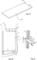
- FIG. 20 A second embodiment of a Dewar flask is in Fig. 20 shown. It is evident in Fig. 20 in particular the double wall with the vacuum insulation 12 and the lid 5 (not shown) closed opening 6.
- a carousel 18 In the interior of the Dewar is again a carousel 18, which carries on its bottom plate 19 a plurality of storage cassettes (not shown).
- FIG. 6-8 an advantageous storage cassette 20 is shown. It has two parallel, vertical side walls 30 and perpendicular thereto via a vertical rear wall 32. Opposite the rear wall 32, the storage cassette 20 is open, so that the accommodated in the storage cassette 20 sample plates can be accessed.
- a ceiling part 34 is arranged, on which the side walls 30 and the rear wall 32 and an upwardly projecting handle 36 are attached.
- the handle 36 serves the picking device described below for gripping the cassette.
- a bottom part 38 is arranged, on which in turn the side walls 30 and the rear wall 32 are attached.
- the storage cassette forms a plurality of superimposed bearings, each of which can accommodate a sample plate. They are designed to provide high mechanical accuracy over a very wide temperature range. They also have centering and transport devices that allow high mechanical positioning accuracy and automatic transport.
- each bearing point of several angles 40, 42 is formed. These angles project inwardly from side walls 30 (angle 40) and rear wall 32 (angle 42), respectively, and provide side and rear supports for the sample plates.
- the angle 42 on the rear wall 32 have at its front edge bent, ie bent upwards, retaining elements 44 (see Fig. 7 ), which engage in the inserted sample plate, for example, behind a rear wall thereof, so as to prevent them from slipping forward.
- the side walls 30 of the bearing cassettes 20 are bent over at the front and thus form bent regions 46, with which the storage cassette 20 is positioned laterally in the Dewar 4.
- the bent portions 46 each lie laterally against a stationary in the carousel 18 arranged holding member 48.
- the bent regions 46 increase the stability of the storage cassettes.
- a vertical bead 47 extends in each side wall.
- the ceiling part 34 and the bottom part 38 are formed by bent portions of the same piece of sheet metal.
- the angle 40, 42 may be formed by bent portions of the sheet metal part. This simplifies the manufacture of the storage cassette and makes the storage cassette robust and temperature-resistant.
- predetermined bending points 39 in particular in the form of elongated holes or slots are provided which simplify a location-accurate bending of the sheet metal piece during manufacture.
- the outline of the sheet metal piece is cut by means of laser processing, and also the predetermined bending points 39 are created in the same operation with the laser, so that a high relative position accuracy is ensured.
- the illustrated storage cassette is not only suitable for use in the storage facility described herein but also for use for other purposes, e.g. generally for storage of laboratory objects (such as microtiter plates) inside and outside of climate cabinets.
- the picking device 8 is in Fig. 10 shown in more detail. It has a carriage 50, which can be moved horizontally along a stationary in the bearing system 1 arranged first rail 52, to which a first horizontal drive 54 is provided. In the carriage 50, a carriage 56 is arranged, which can be moved horizontally along a second rail 58, which is arranged perpendicular to the first rail on the carriage 50. For this purpose, a second horizontal drive 59 is provided. In this way, the carriage 56 is horizontally movable in all directions.
- At least one cassette lift 60 is arranged on the carriage 56, with which bearing cassettes can be removed from the dewar vessels 4 in the vertical direction and inserted again into them.
- two such cassette lifts 60 are provided. They are mounted rotated by 180 ° to each other. This arrangement was chosen because in the execution Fig. 1 and 2 Also, the Dewar barrels are arranged in two mutually rotated by 180 ° rows, so that per row of Dewar vessels a correspondingly oriented cassette lift 60 is available. Alternatively, only one cassette lift 60 could be provided, which can be rotated about a vertical axis by 180 °. Or the Dewar vessels 4 can all be the same orientation, in which case a single, non-rotatable cassette lift is sufficient.
- An envelope device 100 is further provided on the carriage 56. In the execution after Fig. 10 This handling device 100 is arranged between the two cassette lifts 60.
- the structure and function of the handling device 100 essentially correspond to those of the handling device WO 02/059251 ,
- the handling device 100 comprises a vertical guide 102, on which a folding carriage 104 is arranged to be automatically movable in the vertical direction.
- a horizontally extendable blade 106 is provided at the envelope slide 104.
- the blade 106 may preferably be pivoted about at least 180 ° about a vertical axis, so that in the embodiment of Fig. 10 optionally in the storage cassettes 20 of the opposing cassette lifts 60 retract and there record a test plate or can store. Further, it can also be pivoted in the longitudinal direction of the storage facility 1 be arranged to a terminal in the storage facility 1 arranged transfer station 108 (see Fig. 2 ) place or pick up a sample plate.
- a climate chamber 110 can be provided at the location of the transfer station 108, which is able to exchange laboratory objects or bearing plates with the transfer station 108.
- a sampling device can be provided on the carriage 56 with which it is possible to remove a sample tube from a sample plate taken from a cassette or to add a sample tube to such a plate without the sample plate having to leave the climatic chamber 2. This measure reduces the residence time of the samples outside the storage temperature and increases the sample throughput by reducing the routes.
- a suitable construction of a sampling device is shown in FIG EP2078961 disclosed.
- Fig. 11 shows a first embodiment of a cassette lift.
- each cassette lift 60 has a plurality of telescopically extendable telescopic sections 62, 64 and a corresponding number of vertical drives 66, 68th
- a first telescoping section 62 is fixedly mounted on the carriage 56.
- a first vertical rail 69 is arranged, on which a first vertical drive 66 is arranged displaceably.
- the vertical drive 66 is connected via a first guide 70 to the first vertical rail 69 and engages with a pinion 72 in a rack 74 on the first telescopic section 62 a.
- a second vertical rail 76 is further arranged, on which the second telescopic section 64 is mounted vertically movable. It is deflected by a at the upper end of the first telescopic section 62 deflected, flexible, tensile low-temperature-resistant Band or a chain 80 connected to the first vertical drive 66, so that a lowering or raising the first vertical drive 66 causes a raising or lowering of the second telescopic section 66 by the same height relative to the first telescopic section 62.
- the second telescopic section 64 can be extended or retracted telescopically.
- a third vertical rail 82 is arranged, on which an arm 84 of the cassette lift 60 is mounted vertically movable.
- the second vertical drive 68 is configured to move the arm 84 vertically relative to the second telescoping section 64.
- the second vertical drive 68 engages with a pinion in a toothed rack 86 on the second telescopic section 64.
- a gripper device 88 Arranged on the arm 84 is a gripper device 88 with a gripper drive 89, with which the gripping handle 36 of a storage cassette 20 can be gripped from above.
- FIGS. 15-18 show a third embodiment of a cassette lift 60. It corresponds structurally that after Fig. 12 - 14 , with the differences described below.
- the third embodiment of the cassette lift is not based on a telescopic arrangement of elements. Rather, the chain 80 together with rollers 96, 97 a pulley, which serves to lower the gripper device 88 in the Dewar 4. For this purpose, the chain is deflected over at least one lower and at least one upper roller 96 and 97, cf. Fig. 18 , One of the Rolls, advantageously the lower roller 96, is displaceable over the vertical drive 66 in the vertical direction, while the other roller and the upper end of the chain 80 are vertically stationary.
- the vertical drive is arranged on the first vertical rail 69 of a rail carrier 62 ( Fig. 18 ).
- the rail support 62 corresponds to the first telescopic element 62 of the preceding embodiments and is fixedly arranged on the carriage 56.
- the deflected at the upper end of the cassette lift 60 chain 80 depends vertically downwards and carries at its lower end the gripper device 88 which, as in the second embodiment of the cassette lift, is formed by an electromagnet, with which the respective storage cassette can be magnetically held.
- the gripper device 88 exemplifies the same shape as the handle 36 Fig. 6 However, it forms a separate element from the handle 36.
- the handle 36 can be omitted if the storage cassette 20 can be magnetically held at least at its upper end.
- a guide element 98 is provided which is longitudinally displaceably guided on a second vertical rail 76.
- the second vertical rail 76 is also arranged on the rail carrier 62.
- the guide member 98 forms a lateral guide for the chain 80, preferably an eyelet 116, through which the chain 80 passes.
- the guide element 98 is at a stop at the lower end of the second vertical rail 76. If the storage cassette 20 is raised, so the eyelet strikes 116 on the gripper 88 and is taken, see. Fig. 16 - 18 ,
- FIGS. 15-18 has, among other things, the advantage that it only has a vertical drive 66 needed, which can also be arranged relatively high above the lift and does not have to be lowered into the very cold areas of the storage facility.
- the use of a pulley is also advantageous because it allows to reduce the vertical stroke of the engine and so the overall height.
- the chain or band 80 need not necessarily be arranged in a pulley.
- the gripper device 88 for gripping the storage cassettes 20 on a chain or a belt 80 can be lowered into the dewars.
- a centering element 95 is provided on the dewar 2, as shown in FIGS. 20 and 21 is shown.
- this centering element 95 is arranged in the opening 6.
- the centering element 95 has an upwardly widening upper collar 96 and a downwardly widening lower collar 97, which simplify insertion of the storage cassette 20 from above or below. It is aligned with lateral feet 98 in the opening 6 in the correct position relative to the carousel 18 and it forms at least one guide opening 99 in which the storage cassette is guided horizontally when pulling out of or into the dewar. Between the guide opening 99 and a bearing shaft remains as low as possible horizontal clearance of, for example, a maximum of 5 mm.
- the centering element has a plurality of guide openings 99, which are arranged at different distances from the axis of rotation 16.
- the distances of the guide openings 99 to Rotary axis 16 correspond to the radii of the circles of the storage shafts in the carousel 18th
- On the blade 106 is preferably and as in Fig. 19 Shown at least one upwardly directed, in particular obliquely upwardly directed, holding element 107, for example in the form of a finger, arranged, namely at that end of the blade 106, with which it is moved into the first storage cassettes 20.
- holding element 107 for example in the form of a finger, arranged, namely at that end of the blade 106, with which it is moved into the first storage cassettes 20.
- two such holding elements 107 are spaced from each other. These holding elements 107 serve to secure the laboratory objects on the blade from behind, so that they do not fall off the blade.
- the rear wall 32 of the storage cassettes 20 is constructed so that the holding elements 107 find space to be brought from below behind a held in the storage cassette 20 laboratory object.
- the rear wall 32 as in Fig. 7 shown in two vertically extending side regions 32a set back relative to its central region 32b.
- a first region (middle region 32b) of the rear wall 32 forms a spacer, with respect to which at least one second region (in FIG Fig. 7 the side portions 32a) is set back, such that the holding elements 107 can be inserted behind the laboratory objects held in the storage cassette, ie that the holding elements 107 can be accommodated behind the laboratory object held in the storage cassette.
- the second region 32a is recessed from the first region 32b, but the second region 32a of the back wall may be recessed.
- the storage facility 1 as well as the storage cassettes 20 for storage of sample tubes.
- they are also suitable for the storage of samples in other forms, generally suitable for the storage of laboratory objects. These may be, for example, biological or chemical samples.
- a typical application also concerns the storage of laboratory samples in microtiter plates, in which case the sample plates are designed as microtiter plates.
- sample containers eg bottles are used, which each contain only one sample.
Landscapes
- Engineering & Computer Science (AREA)
- Chemical & Material Sciences (AREA)
- Physics & Mathematics (AREA)
- Combustion & Propulsion (AREA)
- Mechanical Engineering (AREA)
- Thermal Sciences (AREA)
- General Engineering & Computer Science (AREA)
- Health & Medical Sciences (AREA)
- Life Sciences & Earth Sciences (AREA)
- Analytical Chemistry (AREA)
- Biochemistry (AREA)
- General Health & Medical Sciences (AREA)
- General Physics & Mathematics (AREA)
- Immunology (AREA)
- Pathology (AREA)
- Chemical Kinetics & Catalysis (AREA)
- Robotics (AREA)
- Warehouses Or Storage Devices (AREA)
- Automatic Analysis And Handling Materials Therefor (AREA)
Claims (18)
- Agencement de stockage pour stocker des objets de laboratoire comprenant
une chambre (3),
au moins un flacon Dewar (4) disposé dans la chambre (3) pour stocker les objets de laboratoire à une température de stockage Ts < Tc, où Tc est une température de la chambre (3),
plusieurs cassettes de stockage (20) disposées dans le flacon Dewar (4), chaque cassette de stockage (20) formant une pluralité de sites de stockage disposés les uns au-dessus des autres pour recevoir les objets de laboratoire, et
un dispositif de prélèvement (8), qui est disposé dans la chambre (3) de manière mobile au-dessus du flacon Dewar ou des flacons Dewar (4) et qui présente au moins un élévateur de cassette (60), afin de retirer des flacons Dewar (4) les cassettes de stockage (20) dans la direction verticale et de les y insérer à nouveau,
caractérisé en ce qu'un carrousel rotatif (18) est prévu dans le flacon Dewar, sur lequel sont disposées les cassettes de stockage (20),
en ce qu'il est prévu au moins un élément de centrage (90, 91, 95) dans lequel une cassette de stockage (20) peut être insérée, afin d'aligner horizontalement la cassette de stockage (20),
en ce que l'élément de centrage (95) est disposé sur le flacon Dewar, l'élément de centrage (95) présentant plusieurs ouvertures de guidage (99) pour recevoir respectivement une cassette de stockage. - Agencement de stockage selon la revendication 1, dans lequel un couvercle (5) qui peut être ouvert automatiquement est disposé sur le dessus d'au moins un flacon Dewar (4), afin d'accéder aux cassettes de stockage (20) dans le flacon Dewar (4) par le dessus.
- Agencement de stockage selon l'une des revendications précédentes, dans lequel la chambre (3) est une chambre de refroidissement avec un dispositif de refroidissement (9a), dans lequel une température de chambre Tc < 0°C peut être produite dans la chambre avec le dispositif de refroidissement.
- Agencement de stockage selon l'une des revendications précédentes, dans lequel plusieurs flacons Dewar (4) sont disposés dans la chambre (3), lesquels flacons Dewar pouvant être chargés par le dispositif de prélèvement (8), le dispositif de prélèvement étant commun à tous les flacons Dewar.
- Agencement de stockage selon l'une des revendications précédentes, dans lequel l'élévateur de cassette (60) présente une chaîne ou une courroie (80, 94), sur laquelle un dispositif de préhension (88) pour saisir les cassettes de stockage (20) peut être abaissé dans l'au moins un flacon Dewar (4).
- Agencement de stockage selon la revendication 5, dans lequel la chaîne ou la courroie (80) est disposée dans une poulie (80, 96, 97).
- Agencement de stockage selon l'une des revendications précédentes, dans lequel l'élévateur de cassette (60) comporte un dispositif de préhension (88) pour saisir les cassettes de stockage (20), dans lequel le dispositif de préhension est réalisé sous la forme d'un électroaimant, avec lequel la cassette de stockage (20) peut être retenue magnétiquement.
- Agencement de stockage selon la revendication 6, dans lequel la poulie (80, 96, 97) présente au moins un rouleau (97) fixe verticalement et au moins un rouleau (96) déplaçable verticalement avec un entraînement vertical (66), autour duquel la chaîne ou la courroie (80) est déplacée.
- Agencement de stockage selon l'une des revendications précédentes, dans lequel l'élément de centrage (90, 91) est disposé à une hauteur fixe.
- Agencement de stockage selon l'une des revendications précédentes, comportant au moins deux éléments de centrage (90, 91) disposés l'un au-dessus de l'autre à distance l'un de l'autre, dans lequel la cassette de stockage surélevée (20) est insérée, et en particulier dans lequel la cassette de stockage surélevée est guidée horizontalement au niveau d'une extrémité supérieure d'un élément supérieur (90) des éléments de centrage et au niveau d'une extrémité inférieure d'un élément inférieur (91) des éléments de centrage.
- Agencement de stockage selon l'une des revendications précédentes, dans lequel l'élément de centrage est disposé dans une ouverture (6) du flacon Dewar (4).
- Agencement de stockage selon l'une des revendications précédentes, dans lequel le dispositif de prélèvement (8) présente un dispositif de manipulation (100) qui présente une pelle (106) qui peut être déplacée verticalement et prolongée horizontalement dans une cassette de stockage (20) surélevée.
- Agencement de stockage selon la revendication 12, dans lequel le dispositif de prélèvement (8) comporte deux élévateurs de cassette (60), entre lesquels est disposé le dispositif de manipulation (100).
- Agencement de stockage selon la revendication 13, dans lequel au moins deux rangées de flacons Dewar (5) orientés en rotation de 180° l'un par rapport à l'autre sont disposées dans la chambre (3), et dans lequel les deux élévateurs de cassette (60) sont également disposés en rotation l'un par rapport à l'autre de 180°.
- Agencement de stockage selon l'une des revendications 12 à 14, dans lequel au moins un élément de support (107) dirigé vers le haut est disposé à une extrémité de la pelle (106) qui peut être insérée dans les cassettes de stockage (20), afin de fixer les objets de laboratoire sur la pelle (106), et dans lequel une paroi arrière (32) des cassettes de stockage (20) dans au moins une première région (32b) forme un espaceur, par rapport auquel au moins une seconde région (32a)de la paroi arrière (32) est omise ou en retrait de telle sorte que l'élément de support (107) a un espace derrière l'objet de laboratoire.
- Agencement de stockage selon l'une des revendications précédentes, dans lequel le dispositif de prélèvement (8) comporte un chariot (56) qui peut être déplacé horizontalement dans deux directions, l'élévateur de cassette (60) étant disposé sur le chariot (56).
- Agencement de stockage selon la revendication 16, dans lequel le chariot (56) est relié au boîtier par l'intermédiaire d'un premier et d'un deuxième rail (52, 58), le premier et le deuxième rail (52, 58) étant perpendiculaires entre eux et étant disposés plus haut que le flacon Dewar (5).
- Agencement de stockage selon l'une des revendications précédentes, qui présente un boîtier (2) qui entoure la chambre (3).
Priority Applications (2)
| Application Number | Priority Date | Filing Date | Title |
|---|---|---|---|
| EP20215024.9A EP3812674B1 (fr) | 2010-11-24 | 2011-11-21 | Entrepôt destiné à l'entreposage des objets de laboratoire à basses températures |
| EP19185530.3A EP3581864B1 (fr) | 2010-11-24 | 2011-11-21 | Installation de stockage d'objets de laboratoire à basses températures |
Applications Claiming Priority (1)
| Application Number | Priority Date | Filing Date | Title |
|---|---|---|---|
| CH01968/10A CH704128A1 (de) | 2010-11-24 | 2010-11-24 | Lageranlage für tiefe Temperaturen und Lagerkassette für Laborobjekte. |
Related Child Applications (3)
| Application Number | Title | Priority Date | Filing Date |
|---|---|---|---|
| EP19185530.3A Division EP3581864B1 (fr) | 2010-11-24 | 2011-11-21 | Installation de stockage d'objets de laboratoire à basses températures |
| EP19185530.3A Division-Into EP3581864B1 (fr) | 2010-11-24 | 2011-11-21 | Installation de stockage d'objets de laboratoire à basses températures |
| EP20215024.9A Division EP3812674B1 (fr) | 2010-11-24 | 2011-11-21 | Entrepôt destiné à l'entreposage des objets de laboratoire à basses températures |
Publications (3)
| Publication Number | Publication Date |
|---|---|
| EP2458308A2 EP2458308A2 (fr) | 2012-05-30 |
| EP2458308A3 EP2458308A3 (fr) | 2015-07-15 |
| EP2458308B1 true EP2458308B1 (fr) | 2019-08-14 |
Family
ID=45098787
Family Applications (4)
| Application Number | Title | Priority Date | Filing Date |
|---|---|---|---|
| EP11009209.5A Active EP2458309B1 (fr) | 2010-11-24 | 2011-11-21 | Caisson de stockage pour objets de laboratoire |
| EP11009208.7A Active EP2458308B1 (fr) | 2010-11-24 | 2011-11-21 | Installation de stockage d'objets de laboratoire à basses températures |
| EP20215024.9A Active EP3812674B1 (fr) | 2010-11-24 | 2011-11-21 | Entrepôt destiné à l'entreposage des objets de laboratoire à basses températures |
| EP19185530.3A Active EP3581864B1 (fr) | 2010-11-24 | 2011-11-21 | Installation de stockage d'objets de laboratoire à basses températures |
Family Applications Before (1)
| Application Number | Title | Priority Date | Filing Date |
|---|---|---|---|
| EP11009209.5A Active EP2458309B1 (fr) | 2010-11-24 | 2011-11-21 | Caisson de stockage pour objets de laboratoire |
Family Applications After (2)
| Application Number | Title | Priority Date | Filing Date |
|---|---|---|---|
| EP20215024.9A Active EP3812674B1 (fr) | 2010-11-24 | 2011-11-21 | Entrepôt destiné à l'entreposage des objets de laboratoire à basses températures |
| EP19185530.3A Active EP3581864B1 (fr) | 2010-11-24 | 2011-11-21 | Installation de stockage d'objets de laboratoire à basses températures |
Country Status (3)
| Country | Link |
|---|---|
| US (2) | US9784495B2 (fr) |
| EP (4) | EP2458309B1 (fr) |
| CH (1) | CH704128A1 (fr) |
Families Citing this family (35)
| Publication number | Priority date | Publication date | Assignee | Title |
|---|---|---|---|---|
| EP2208951B1 (fr) | 2009-01-19 | 2018-05-30 | Liconic Ag | Stockage automatisé basse température pour échantillons de laboratoire avec un accès automatisé |
| DK2491403T3 (da) * | 2009-10-19 | 2019-09-23 | Brooks Automation Inc | Modulopbygget prøvelager og fremgangsmåde til transport af prøvebeholdere i et modulopbygget prøvelager |
| HK1221375A1 (zh) * | 2013-08-08 | 2017-06-02 | Sanofi-Aventis Deutschland Gmbh | 用於低溫貯藏應用場合中的回收組件 |
| EP3077738A4 (fr) * | 2013-12-07 | 2017-06-07 | Trumed Systems, Inc. | Stockage intelligent automatisé de produits thermosensibles |
| US20150291357A1 (en) * | 2014-04-14 | 2015-10-15 | Sergey N. Razumov | Robotic pickup point for order fulfillment system |
| PL2998669T3 (pl) | 2014-09-22 | 2018-11-30 | Liconic Ag | Urządzenie do przechowywania w niskiej temperaturze z zespołem do obsługi kaset |
| US9709314B2 (en) | 2014-09-22 | 2017-07-18 | Liconic Ag | Low-temperature storage device with rotating lock chamber |
| CN104773425B (zh) * | 2015-03-24 | 2017-03-22 | 苏州优点优唯医疗科技有限公司 | 一种智能冷链储物库 |
| WO2016160984A1 (fr) * | 2015-03-30 | 2016-10-06 | Brooks Automation, Inc. | Système de stockage cryogénique automatisé |
| EP3278040B1 (fr) * | 2015-03-30 | 2023-08-02 | Azenta, Inc. | Congélateur cryogénique |
| WO2017049416A1 (fr) * | 2015-09-24 | 2017-03-30 | Liconic Ag | Dispositif de stockage à basse température et de manutention de tubes-sondes dans des supports de tubes |
| CN105857937B (zh) * | 2016-04-28 | 2018-05-08 | 上海原能健康管理有限公司 | 冻存管存取装置以及液氮罐存取系统 |
| CN105857932B (zh) * | 2016-04-28 | 2018-02-13 | 上海原能健康管理有限公司 | 冻存管存取装置 |
| CN105857941B (zh) * | 2016-04-28 | 2018-06-29 | 上海原能健康管理有限公司 | 冻存管存取装置 |
| CN106560419B (zh) * | 2016-11-14 | 2018-10-19 | 上海原能细胞医学技术有限公司 | 管阵式液氮罐 |
| CN106628783B (zh) * | 2016-12-28 | 2022-04-29 | 上海原能细胞生物低温设备有限公司 | 全自动超低温蜂巢型生物样本库 |
| CN107062731A (zh) * | 2017-02-20 | 2017-08-18 | 上海原能细胞医学技术有限公司 | 自动化存储装置及其运行方法 |
| EP3467408B1 (fr) | 2017-10-05 | 2024-02-21 | Liconic AG | Méthode de fonctionnement d'une installation de stockage à basse température ayant un appareil de retrait d'azote dans un bâtiment |
| CN109928071A (zh) * | 2017-12-15 | 2019-06-25 | 国玺干细胞应用技术股份有限公司 | 智能科技生物产品低温储存设备 |
| CN109275657B (zh) * | 2018-09-17 | 2023-07-04 | 上海原能细胞生物低温设备有限公司 | 一种螺旋升降式低温存储装置 |
| CN209480359U (zh) * | 2018-12-27 | 2019-10-11 | 上海原能细胞生物低温设备有限公司 | 一种液氮罐 |
| WO2020231941A1 (fr) * | 2019-05-13 | 2020-11-19 | Abt Holding Company | Appareil et procédé de cryostockage et de manutention d'une pluralité d'unités de conteneur |
| CN111422404B (zh) * | 2020-05-11 | 2024-06-14 | 上海原能细胞生物低温设备有限公司 | 样本存储设备和样本存取方法 |
| CN111959953B (zh) * | 2020-09-03 | 2024-06-21 | 上海原能细胞生物低温设备有限公司 | 一种提篮式样本低温储存装置 |
| CN112224671B (zh) * | 2020-09-30 | 2024-11-26 | 上海原能细胞生物低温设备有限公司 | 一种罐体转动开盖存储装置 |
| CN112208942B (zh) * | 2020-10-19 | 2024-06-14 | 上海原能细胞生物低温设备有限公司 | 存取设备 |
| CN112705285A (zh) * | 2020-12-29 | 2021-04-27 | 陈文强 | 一种医院检验科专用样本储放转移装置 |
| CN112452380A (zh) * | 2020-12-29 | 2021-03-09 | 陈文强 | 一种医院检验科多位一体工作台 |
| CN112705287A (zh) * | 2020-12-29 | 2021-04-27 | 陈文强 | 一种医用多功能收储工作台 |
| CN112705286A (zh) * | 2020-12-29 | 2021-04-27 | 陈文强 | 一种医院检验科医疗样本存储箱 |
| CN114279148A (zh) * | 2021-01-15 | 2022-04-05 | 青岛海特生物医疗有限公司 | 疫苗存储发放系统及接种方法 |
| CN114279147A (zh) * | 2021-01-15 | 2022-04-05 | 青岛海特生物医疗有限公司 | 疫苗冷藏取放一体库 |
| CN113501247A (zh) * | 2021-08-26 | 2021-10-15 | 义乌市铂玥信息技术咨询有限公司 | 转笼式超低温生物样本自动化存取系统 |
| FR3140876B1 (fr) * | 2022-10-13 | 2024-09-06 | Exotec | Organe longiligne présentant au moins une crémaillère, rack de stockage comprenant un tel organe longiligne, et système de transport et de stockage comprenant un tel rack de stockage |
| CN117002885A (zh) * | 2023-08-03 | 2023-11-07 | 上海原能细胞生物低温设备有限公司 | 一种移动式上舱室及其双侧分体式样本存储系统 |
Family Cites Families (48)
| Publication number | Priority date | Publication date | Assignee | Title |
|---|---|---|---|---|
| US3272579A (en) | 1964-08-24 | 1966-09-13 | Cryogenic Eng Co | Cryogenic storage vessel with station selector |
| US3782133A (en) | 1972-08-14 | 1974-01-01 | Air Liquide | Low temperature storage vessel |
| US4250266A (en) | 1979-12-19 | 1981-02-10 | Honeywell Inc. | Automated micro-organism culture growth and detection instrument |
| US4771900A (en) * | 1987-04-09 | 1988-09-20 | Nalge Company | Storage rack for box-like container |
| US4907889A (en) | 1988-03-24 | 1990-03-13 | Automation Equipment Company | Video cassette library retrieval and sequencing system |
| US4832195A (en) * | 1988-05-02 | 1989-05-23 | Dahl Ernest A | Compact storage files |
| US4969336A (en) * | 1989-08-04 | 1990-11-13 | Cryo-Cell International, Inc. | Cryogenic storage apparatus, particularly with automatic retrieval |
| US5131250A (en) | 1991-02-08 | 1992-07-21 | The National Machinery Company | Flat die thread roller |
| US5192506A (en) | 1991-02-14 | 1993-03-09 | P B Diagnostic Systems, Inc. | Incubator port closure for automated assay system |
| US5233844A (en) | 1991-08-15 | 1993-08-10 | Cryo-Cell International, Inc. | Storage apparatus, particularly with automatic insertion and retrieval |
| FR2680658B1 (fr) * | 1991-08-30 | 1993-11-19 | Air Liquide | Panier de rangement de boitiers individuels et conteneur cryogenique. |
| US5266272A (en) | 1991-10-31 | 1993-11-30 | Baxter Diagnostics Inc. | Specimen processing and analyzing systems with a station for holding specimen trays during processing |
| US5345395A (en) | 1991-10-31 | 1994-09-06 | Baxter Diagnostics Inc. | Specimen processing and analyzing systems and methods using photometry |
| AU656826B2 (en) | 1991-10-31 | 1995-02-16 | Microscan, Inc. | Specimen processing and analyzing systems with associated fluid dispensing apparatus |
| US5240139A (en) | 1992-03-06 | 1993-08-31 | Munroe Chirnomas | Package vending machine |
| US5735587A (en) | 1995-02-06 | 1998-04-07 | Liconic Ag | Climatic cabinet, turntable and use of the turntable |
| SE9602404D0 (sv) | 1996-06-18 | 1996-06-18 | Jan Dranger | Furniture device |
| EP0853657B1 (fr) | 1996-08-05 | 2007-12-26 | Thermo Electron LED GmbH | Dispositif de stockage d'objets, station de stockage et armoire de climatisation |
| US5921102A (en) | 1997-03-28 | 1999-07-13 | Cryo-Cell International, Inc. | Storage apparatus particularly with automatic insertion and retrieval |
| US6068393A (en) | 1997-11-05 | 2000-05-30 | Zymark Corporation | Robotic system for processing chemical products |
| CH690645C1 (de) | 1999-09-02 | 2002-08-30 | Liconic Ag | LAGERANLAGE UND LAGERBEHäLTNIS MIT LAGERANLAGE |
| WO2001083694A2 (fr) | 2000-04-28 | 2001-11-08 | Biocrystal Ltd. | Support pour dispositifs de culture de cellules |
| DE10024581A1 (de) | 2000-05-19 | 2001-11-29 | Kendro Lab Prod Gmbh | Klimaschrank |
| DE10058564A1 (de) | 2000-11-24 | 2002-06-06 | Kendro Lab Prod Gmbh | Objektlagerstation und Klimaschrank |
| EP1897935B1 (fr) | 2001-01-26 | 2010-01-13 | Liconic Ag | Armoire de stockage climatisée |
| GB0209025D0 (en) | 2002-04-19 | 2002-05-29 | Randox Lab Ltd | Assay device incubator |
| US6694767B2 (en) * | 2002-06-19 | 2004-02-24 | Jouan | Work enclosure having article supports that obstruct access openings |
| ITBO20020607A1 (it) | 2002-09-26 | 2004-03-27 | Cryorobotics | Sistema automatico per la conservazione a temperatura |
| US7314341B2 (en) | 2003-01-10 | 2008-01-01 | Liconic Ag | Automatic storage device and climate controlled cabinet with such a device |
| DE10332799B4 (de) * | 2003-07-18 | 2007-03-01 | Fraunhofer-Gesellschaft zur Förderung der angewandten Forschung e.V. | Vorrichtung und Verfahren zur Handhabung einer Probe |
| JP2005143873A (ja) | 2003-11-17 | 2005-06-09 | Taiyo Nippon Sanso Corp | 凍結保存容器 |
| DE102004008496B3 (de) | 2004-02-20 | 2005-07-14 | Fraunhofer-Gesellschaft zur Förderung der angewandten Forschung e.V. | Verschluss für eine Kühlbehälteröffnung |
| US20060006774A1 (en) | 2004-07-09 | 2006-01-12 | Kendro Laboratory Products, Lp | Microplate storage apparatus and method |
| EP1634496A1 (fr) * | 2004-09-14 | 2006-03-15 | The Automation Partnership (Cambridge) Limited | Systeme de stockage a temperature ultra-basse |
| US20060150659A1 (en) | 2004-12-10 | 2006-07-13 | Sidor Michael R | Vertical storage systems |
| DE102005001888A1 (de) | 2005-01-14 | 2006-07-20 | Liconic Ag | Automatische Lagervorrichtung und Klimaschrank für Laborgüter |
| US20090026905A1 (en) | 2005-01-12 | 2009-01-29 | Malin Cosmas G | Automatic storage device and climate controlled cabinet for laboratory objects |
| DK177390B1 (da) | 2006-03-13 | 2013-03-04 | Teddy Kristensen | Udgangsemne til en reol |
| DE102007004072A1 (de) | 2007-01-26 | 2008-07-31 | Thermo Electron Led Gmbh | Objektlagervorrichtung mit Schüttelfunktion |
| EP1972874B1 (fr) | 2007-03-20 | 2019-02-13 | Liconic Ag | Stockage de substances automatisé |
| EP1975626A1 (fr) * | 2007-03-29 | 2008-10-01 | F. Hoffmann-Roche AG | Empileuse pour des plaques à microtitre |
| US20090140616A1 (en) | 2007-12-04 | 2009-06-04 | Anthony Fox | Trash compactor cabinet |
| EP2078961B1 (fr) | 2008-01-08 | 2020-04-08 | Liconic Ag | Dispositif de manipulation d'échantillons de laboratoire |
| JP4648444B2 (ja) * | 2008-01-18 | 2011-03-09 | 大陽日酸株式会社 | グローブボックス |
| DE102008057981B4 (de) | 2008-11-19 | 2010-09-02 | Fraunhofer-Gesellschaft zur Förderung der angewandten Forschung e.V. | Kryospeichereinrichtung |
| IT1408715B1 (it) * | 2008-12-17 | 2014-07-03 | Parmegiani | Dispositivo e metodo per la sterilizzazione di azoto liquido in fase liquida mediante radiazione ultravioletta. |
| EP2208951B1 (fr) | 2009-01-19 | 2018-05-30 | Liconic Ag | Stockage automatisé basse température pour échantillons de laboratoire avec un accès automatisé |
| WO2012033994A2 (fr) * | 2010-09-10 | 2012-03-15 | Hamilton Storage Technologies, Inc. | Cassette de stockage d'échantillons pour températures ultra-basses ou cryogéniques |
-
2010
- 2010-11-24 CH CH01968/10A patent/CH704128A1/de not_active Application Discontinuation
-
2011
- 2011-11-21 EP EP11009209.5A patent/EP2458309B1/fr active Active
- 2011-11-21 EP EP11009208.7A patent/EP2458308B1/fr active Active
- 2011-11-21 EP EP20215024.9A patent/EP3812674B1/fr active Active
- 2011-11-21 EP EP19185530.3A patent/EP3581864B1/fr active Active
- 2011-11-23 US US13/304,098 patent/US9784495B2/en active Active
- 2011-11-23 US US13/304,079 patent/US9005542B2/en active Active
Non-Patent Citations (1)
| Title |
|---|
| None * |
Also Published As
| Publication number | Publication date |
|---|---|
| EP3581864A1 (fr) | 2019-12-18 |
| EP2458309A2 (fr) | 2012-05-30 |
| US20120134898A1 (en) | 2012-05-31 |
| EP3812674A1 (fr) | 2021-04-28 |
| EP2458308A3 (fr) | 2015-07-15 |
| EP3581864B1 (fr) | 2021-01-06 |
| EP3812674B1 (fr) | 2022-04-13 |
| EP2458308A2 (fr) | 2012-05-30 |
| US9005542B2 (en) | 2015-04-14 |
| CH704128A1 (de) | 2012-05-31 |
| EP2458309A3 (fr) | 2015-07-15 |
| US20120134897A1 (en) | 2012-05-31 |
| EP2458309B1 (fr) | 2019-08-07 |
| US9784495B2 (en) | 2017-10-10 |
Similar Documents
| Publication | Publication Date | Title |
|---|---|---|
| EP2458308B1 (fr) | Installation de stockage d'objets de laboratoire à basses températures | |
| EP2743614B1 (fr) | Caisson de stockage pour objets de laboratoire | |
| EP1836292B1 (fr) | Dispositif de stockage automatique et armoire climatique pour articles de laboratoire | |
| EP1972874B1 (fr) | Stockage de substances automatisé | |
| EP0853657B1 (fr) | Dispositif de stockage d'objets, station de stockage et armoire de climatisation | |
| DE60125380T2 (de) | Automatisiertes lagerungs- und entnahmegerät für gefrierfächer und entsprechendes verfahren | |
| DE102013101176B4 (de) | Kühlbox mit einem mit röhrchenförmigen Gefäßen bestückten Rack zum automatischen Befüllen mit einem Pipettierautomaten | |
| EP1939561A2 (fr) | Systeme de stockage compact et son utilisation | |
| DE102011012887A1 (de) | Kryospeichereinrichtung | |
| DE102007034197A1 (de) | Vorrichtung zum Be- und Entladen einer Stellplatte einer Gefriertrocknungsanlage und ein Verfahren hierfür | |
| DE202010012318U1 (de) | Vorrichtung zur Lagerung und Bereitstellung von Objekten mit standardisierten Abmaßen | |
| DE102004053170B4 (de) | Lagerungssystem | |
| DE102005001888A1 (de) | Automatische Lagervorrichtung und Klimaschrank für Laborgüter | |
| EP3336455A1 (fr) | Dispositif cryogénique de stockage permettant de stocker des échantillons, en particulier permettant de stocker des échantillons biologiques à basse température | |
| DE102016124722B4 (de) | Handhabungseinrichtung, insbesondere für eine Lagerungsvorrichtung | |
| CH708425B1 (de) | Lageranlage zur Lagerung von Objekten. | |
| DE202021106858U1 (de) | Kommissioniervorrichtung | |
| DE202021106835U1 (de) | Kommissioniervorrichtung | |
| EP1862405B1 (fr) | Procédé destiné à saisir une marchandise à l'aide d'éléments de préhension dans un dispositif de stockage et de déstockage et dispositif correspondant | |
| DE202008013492U1 (de) | Klimaschrank mit zwei Ein- und Ausgabestationen | |
| DE102021107736B4 (de) | Lager, insbesondere Lager für ein Greifmittel einer Lagerungsvorrichtung | |
| EP2385101B1 (fr) | Incubateur dotée de plusieurs stations d'entrée et muni de moyen de transport | |
| DE102022131124A1 (de) | Automatisierte Laborlager mit automatisierter und manueller Schleuse | |
| DE102015113274A1 (de) | Hochregallager für hängende Waren | |
| CH696687A5 (de) | Regallager mit verschiebbaren Toren. |
Legal Events
| Date | Code | Title | Description |
|---|---|---|---|
| PUAI | Public reference made under article 153(3) epc to a published international application that has entered the european phase |
Free format text: ORIGINAL CODE: 0009012 |
|
| AK | Designated contracting states |
Kind code of ref document: A2 Designated state(s): AL AT BE BG CH CY CZ DE DK EE ES FI FR GB GR HR HU IE IS IT LI LT LU LV MC MK MT NL NO PL PT RO RS SE SI SK SM TR |
|
| AX | Request for extension of the european patent |
Extension state: BA ME |
|
| PUAL | Search report despatched |
Free format text: ORIGINAL CODE: 0009013 |
|
| AK | Designated contracting states |
Kind code of ref document: A3 Designated state(s): AL AT BE BG CH CY CZ DE DK EE ES FI FR GB GR HR HU IE IS IT LI LT LU LV MC MK MT NL NO PL PT RO RS SE SI SK SM TR |
|
| AX | Request for extension of the european patent |
Extension state: BA ME |
|
| RIC1 | Information provided on ipc code assigned before grant |
Ipc: F25D 25/00 20060101AFI20150608BHEP Ipc: F25D 3/10 20060101ALI20150608BHEP |
|
| 17P | Request for examination filed |
Effective date: 20160108 |
|
| RBV | Designated contracting states (corrected) |
Designated state(s): AL AT BE BG CH CY CZ DE DK EE ES FI FR GB GR HR HU IE IS IT LI LT LU LV MC MK MT NL NO PL PT RO RS SE SI SK SM TR |
|
| GRAP | Despatch of communication of intention to grant a patent |
Free format text: ORIGINAL CODE: EPIDOSNIGR1 |
|
| STAA | Information on the status of an ep patent application or granted ep patent |
Free format text: STATUS: GRANT OF PATENT IS INTENDED |
|
| INTG | Intention to grant announced |
Effective date: 20190318 |
|
| GRAS | Grant fee paid |
Free format text: ORIGINAL CODE: EPIDOSNIGR3 |
|
| GRAA | (expected) grant |
Free format text: ORIGINAL CODE: 0009210 |
|
| STAA | Information on the status of an ep patent application or granted ep patent |
Free format text: STATUS: THE PATENT HAS BEEN GRANTED |
|
| AK | Designated contracting states |
Kind code of ref document: B1 Designated state(s): AL AT BE BG CH CY CZ DE DK EE ES FI FR GB GR HR HU IE IS IT LI LT LU LV MC MK MT NL NO PL PT RO RS SE SI SK SM TR |
|
| REG | Reference to a national code |
Ref country code: GB Ref legal event code: FG4D Free format text: NOT ENGLISH |
|
| REG | Reference to a national code |
Ref country code: CH Ref legal event code: EP Ref country code: AT Ref legal event code: REF Ref document number: 1167520 Country of ref document: AT Kind code of ref document: T Effective date: 20190815 |
|
| REG | Reference to a national code |
Ref country code: DE Ref legal event code: R096 Ref document number: 502011015991 Country of ref document: DE |
|
| REG | Reference to a national code |
Ref country code: IE Ref legal event code: FG4D Free format text: LANGUAGE OF EP DOCUMENT: GERMAN |
|
| REG | Reference to a national code |
Ref country code: NL Ref legal event code: MP Effective date: 20190814 |
|
| REG | Reference to a national code |
Ref country code: LT Ref legal event code: MG4D |
|
| PG25 | Lapsed in a contracting state [announced via postgrant information from national office to epo] |
Ref country code: PT Free format text: LAPSE BECAUSE OF FAILURE TO SUBMIT A TRANSLATION OF THE DESCRIPTION OR TO PAY THE FEE WITHIN THE PRESCRIBED TIME-LIMIT Effective date: 20191216 Ref country code: NO Free format text: LAPSE BECAUSE OF FAILURE TO SUBMIT A TRANSLATION OF THE DESCRIPTION OR TO PAY THE FEE WITHIN THE PRESCRIBED TIME-LIMIT Effective date: 20191114 Ref country code: NL Free format text: LAPSE BECAUSE OF FAILURE TO SUBMIT A TRANSLATION OF THE DESCRIPTION OR TO PAY THE FEE WITHIN THE PRESCRIBED TIME-LIMIT Effective date: 20190814 Ref country code: BG Free format text: LAPSE BECAUSE OF FAILURE TO SUBMIT A TRANSLATION OF THE DESCRIPTION OR TO PAY THE FEE WITHIN THE PRESCRIBED TIME-LIMIT Effective date: 20191114 Ref country code: FI Free format text: LAPSE BECAUSE OF FAILURE TO SUBMIT A TRANSLATION OF THE DESCRIPTION OR TO PAY THE FEE WITHIN THE PRESCRIBED TIME-LIMIT Effective date: 20190814 Ref country code: LT Free format text: LAPSE BECAUSE OF FAILURE TO SUBMIT A TRANSLATION OF THE DESCRIPTION OR TO PAY THE FEE WITHIN THE PRESCRIBED TIME-LIMIT Effective date: 20190814 Ref country code: SE Free format text: LAPSE BECAUSE OF FAILURE TO SUBMIT A TRANSLATION OF THE DESCRIPTION OR TO PAY THE FEE WITHIN THE PRESCRIBED TIME-LIMIT Effective date: 20190814 Ref country code: HR Free format text: LAPSE BECAUSE OF FAILURE TO SUBMIT A TRANSLATION OF THE DESCRIPTION OR TO PAY THE FEE WITHIN THE PRESCRIBED TIME-LIMIT Effective date: 20190814 |
|
| PG25 | Lapsed in a contracting state [announced via postgrant information from national office to epo] |
Ref country code: AL Free format text: LAPSE BECAUSE OF FAILURE TO SUBMIT A TRANSLATION OF THE DESCRIPTION OR TO PAY THE FEE WITHIN THE PRESCRIBED TIME-LIMIT Effective date: 20190814 Ref country code: LV Free format text: LAPSE BECAUSE OF FAILURE TO SUBMIT A TRANSLATION OF THE DESCRIPTION OR TO PAY THE FEE WITHIN THE PRESCRIBED TIME-LIMIT Effective date: 20190814 Ref country code: IS Free format text: LAPSE BECAUSE OF FAILURE TO SUBMIT A TRANSLATION OF THE DESCRIPTION OR TO PAY THE FEE WITHIN THE PRESCRIBED TIME-LIMIT Effective date: 20191214 Ref country code: GR Free format text: LAPSE BECAUSE OF FAILURE TO SUBMIT A TRANSLATION OF THE DESCRIPTION OR TO PAY THE FEE WITHIN THE PRESCRIBED TIME-LIMIT Effective date: 20191115 Ref country code: RS Free format text: LAPSE BECAUSE OF FAILURE TO SUBMIT A TRANSLATION OF THE DESCRIPTION OR TO PAY THE FEE WITHIN THE PRESCRIBED TIME-LIMIT Effective date: 20190814 Ref country code: ES Free format text: LAPSE BECAUSE OF FAILURE TO SUBMIT A TRANSLATION OF THE DESCRIPTION OR TO PAY THE FEE WITHIN THE PRESCRIBED TIME-LIMIT Effective date: 20190814 |
|
| PG25 | Lapsed in a contracting state [announced via postgrant information from national office to epo] |
Ref country code: TR Free format text: LAPSE BECAUSE OF FAILURE TO SUBMIT A TRANSLATION OF THE DESCRIPTION OR TO PAY THE FEE WITHIN THE PRESCRIBED TIME-LIMIT Effective date: 20190814 |
|
| PG25 | Lapsed in a contracting state [announced via postgrant information from national office to epo] |
Ref country code: IT Free format text: LAPSE BECAUSE OF FAILURE TO SUBMIT A TRANSLATION OF THE DESCRIPTION OR TO PAY THE FEE WITHIN THE PRESCRIBED TIME-LIMIT Effective date: 20190814 Ref country code: PL Free format text: LAPSE BECAUSE OF FAILURE TO SUBMIT A TRANSLATION OF THE DESCRIPTION OR TO PAY THE FEE WITHIN THE PRESCRIBED TIME-LIMIT Effective date: 20190814 Ref country code: DK Free format text: LAPSE BECAUSE OF FAILURE TO SUBMIT A TRANSLATION OF THE DESCRIPTION OR TO PAY THE FEE WITHIN THE PRESCRIBED TIME-LIMIT Effective date: 20190814 Ref country code: EE Free format text: LAPSE BECAUSE OF FAILURE TO SUBMIT A TRANSLATION OF THE DESCRIPTION OR TO PAY THE FEE WITHIN THE PRESCRIBED TIME-LIMIT Effective date: 20190814 Ref country code: RO Free format text: LAPSE BECAUSE OF FAILURE TO SUBMIT A TRANSLATION OF THE DESCRIPTION OR TO PAY THE FEE WITHIN THE PRESCRIBED TIME-LIMIT Effective date: 20190814 |
|
| PG25 | Lapsed in a contracting state [announced via postgrant information from national office to epo] |
Ref country code: CZ Free format text: LAPSE BECAUSE OF FAILURE TO SUBMIT A TRANSLATION OF THE DESCRIPTION OR TO PAY THE FEE WITHIN THE PRESCRIBED TIME-LIMIT Effective date: 20190814 Ref country code: SM Free format text: LAPSE BECAUSE OF FAILURE TO SUBMIT A TRANSLATION OF THE DESCRIPTION OR TO PAY THE FEE WITHIN THE PRESCRIBED TIME-LIMIT Effective date: 20190814 Ref country code: SK Free format text: LAPSE BECAUSE OF FAILURE TO SUBMIT A TRANSLATION OF THE DESCRIPTION OR TO PAY THE FEE WITHIN THE PRESCRIBED TIME-LIMIT Effective date: 20190814 Ref country code: IS Free format text: LAPSE BECAUSE OF FAILURE TO SUBMIT A TRANSLATION OF THE DESCRIPTION OR TO PAY THE FEE WITHIN THE PRESCRIBED TIME-LIMIT Effective date: 20200224 |
|
| REG | Reference to a national code |
Ref country code: DE Ref legal event code: R097 Ref document number: 502011015991 Country of ref document: DE |
|
| PLBE | No opposition filed within time limit |
Free format text: ORIGINAL CODE: 0009261 |
|
| STAA | Information on the status of an ep patent application or granted ep patent |
Free format text: STATUS: NO OPPOSITION FILED WITHIN TIME LIMIT |
|
| PG2D | Information on lapse in contracting state deleted |
Ref country code: IS |
|
| PG25 | Lapsed in a contracting state [announced via postgrant information from national office to epo] |
Ref country code: LU Free format text: LAPSE BECAUSE OF NON-PAYMENT OF DUE FEES Effective date: 20191121 Ref country code: MC Free format text: LAPSE BECAUSE OF FAILURE TO SUBMIT A TRANSLATION OF THE DESCRIPTION OR TO PAY THE FEE WITHIN THE PRESCRIBED TIME-LIMIT Effective date: 20190814 |
|
| 26N | No opposition filed |
Effective date: 20200603 |
|
| REG | Reference to a national code |
Ref country code: BE Ref legal event code: MM Effective date: 20191130 |
|
| PG25 | Lapsed in a contracting state [announced via postgrant information from national office to epo] |
Ref country code: SI Free format text: LAPSE BECAUSE OF FAILURE TO SUBMIT A TRANSLATION OF THE DESCRIPTION OR TO PAY THE FEE WITHIN THE PRESCRIBED TIME-LIMIT Effective date: 20190814 |
|
| PG25 | Lapsed in a contracting state [announced via postgrant information from national office to epo] |
Ref country code: IE Free format text: LAPSE BECAUSE OF NON-PAYMENT OF DUE FEES Effective date: 20191121 |
|
| PG25 | Lapsed in a contracting state [announced via postgrant information from national office to epo] |
Ref country code: BE Free format text: LAPSE BECAUSE OF NON-PAYMENT OF DUE FEES Effective date: 20191130 |
|
| REG | Reference to a national code |
Ref country code: AT Ref legal event code: MM01 Ref document number: 1167520 Country of ref document: AT Kind code of ref document: T Effective date: 20191121 |
|
| PG25 | Lapsed in a contracting state [announced via postgrant information from national office to epo] |
Ref country code: AT Free format text: LAPSE BECAUSE OF NON-PAYMENT OF DUE FEES Effective date: 20191121 |
|
| PG25 | Lapsed in a contracting state [announced via postgrant information from national office to epo] |
Ref country code: CY Free format text: LAPSE BECAUSE OF FAILURE TO SUBMIT A TRANSLATION OF THE DESCRIPTION OR TO PAY THE FEE WITHIN THE PRESCRIBED TIME-LIMIT Effective date: 20190814 |
|
| PG25 | Lapsed in a contracting state [announced via postgrant information from national office to epo] |
Ref country code: MT Free format text: LAPSE BECAUSE OF FAILURE TO SUBMIT A TRANSLATION OF THE DESCRIPTION OR TO PAY THE FEE WITHIN THE PRESCRIBED TIME-LIMIT Effective date: 20190814 Ref country code: HU Free format text: LAPSE BECAUSE OF FAILURE TO SUBMIT A TRANSLATION OF THE DESCRIPTION OR TO PAY THE FEE WITHIN THE PRESCRIBED TIME-LIMIT; INVALID AB INITIO Effective date: 20111121 |
|
| PG25 | Lapsed in a contracting state [announced via postgrant information from national office to epo] |
Ref country code: MK Free format text: LAPSE BECAUSE OF FAILURE TO SUBMIT A TRANSLATION OF THE DESCRIPTION OR TO PAY THE FEE WITHIN THE PRESCRIBED TIME-LIMIT Effective date: 20190814 |
|
| PGFP | Annual fee paid to national office [announced via postgrant information from national office to epo] |
Ref country code: DE Payment date: 20241121 Year of fee payment: 14 |
|
| PGFP | Annual fee paid to national office [announced via postgrant information from national office to epo] |
Ref country code: GB Payment date: 20241120 Year of fee payment: 14 |
|
| PGFP | Annual fee paid to national office [announced via postgrant information from national office to epo] |
Ref country code: FR Payment date: 20241128 Year of fee payment: 14 |
|
| PGFP | Annual fee paid to national office [announced via postgrant information from national office to epo] |
Ref country code: CH Payment date: 20241201 Year of fee payment: 14 |