EP2422708A1 - Multi-focus ultrasound system and method - Google Patents
Multi-focus ultrasound system and method Download PDFInfo
- Publication number
- EP2422708A1 EP2422708A1 EP11178939A EP11178939A EP2422708A1 EP 2422708 A1 EP2422708 A1 EP 2422708A1 EP 11178939 A EP11178939 A EP 11178939A EP 11178939 A EP11178939 A EP 11178939A EP 2422708 A1 EP2422708 A1 EP 2422708A1
- Authority
- EP
- European Patent Office
- Prior art keywords
- lead
- transducer
- probe
- screw
- screw nut
- Prior art date
- Legal status (The legal status is an assumption and is not a legal conclusion. Google has not performed a legal analysis and makes no representation as to the accuracy of the status listed.)
- Granted
Links
- 238000002604 ultrasonography Methods 0.000 title claims description 65
- 238000000034 method Methods 0.000 title description 18
- 239000000523 sample Substances 0.000 claims abstract description 161
- 239000012530 fluid Substances 0.000 claims abstract description 22
- 230000007246 mechanism Effects 0.000 claims description 31
- 230000008878 coupling Effects 0.000 claims description 23
- 238000010168 coupling process Methods 0.000 claims description 23
- 238000005859 coupling reaction Methods 0.000 claims description 23
- 230000033001 locomotion Effects 0.000 description 33
- 210000001519 tissue Anatomy 0.000 description 16
- 230000008859 change Effects 0.000 description 14
- 238000003384 imaging method Methods 0.000 description 9
- 230000007704 transition Effects 0.000 description 6
- 230000006870 function Effects 0.000 description 5
- 238000007789 sealing Methods 0.000 description 5
- 238000009987 spinning Methods 0.000 description 5
- 230000009471 action Effects 0.000 description 4
- 230000009977 dual effect Effects 0.000 description 4
- 230000003534 oscillatory effect Effects 0.000 description 4
- 230000001225 therapeutic effect Effects 0.000 description 4
- 230000010355 oscillation Effects 0.000 description 3
- 230000009286 beneficial effect Effects 0.000 description 2
- 230000008901 benefit Effects 0.000 description 2
- 230000005540 biological transmission Effects 0.000 description 2
- 238000013461 design Methods 0.000 description 2
- 238000002059 diagnostic imaging Methods 0.000 description 2
- 238000004519 manufacturing process Methods 0.000 description 2
- 210000003205 muscle Anatomy 0.000 description 2
- 238000003825 pressing Methods 0.000 description 2
- 238000002560 therapeutic procedure Methods 0.000 description 2
- 230000017531 blood circulation Effects 0.000 description 1
- 210000000988 bone and bone Anatomy 0.000 description 1
- 125000004122 cyclic group Chemical group 0.000 description 1
- 238000002592 echocardiography Methods 0.000 description 1
- 230000000694 effects Effects 0.000 description 1
- 230000003993 interaction Effects 0.000 description 1
- 239000012528 membrane Substances 0.000 description 1
- 239000011295 pitch Substances 0.000 description 1
- 230000008569 process Effects 0.000 description 1
- 230000000717 retained effect Effects 0.000 description 1
- 230000004936 stimulating effect Effects 0.000 description 1
- 230000000638 stimulation Effects 0.000 description 1
- 238000012285 ultrasound imaging Methods 0.000 description 1
- 239000011800 void material Substances 0.000 description 1
Images


Classifications
-
- A—HUMAN NECESSITIES
- A61—MEDICAL OR VETERINARY SCIENCE; HYGIENE
- A61B—DIAGNOSIS; SURGERY; IDENTIFICATION
- A61B8/00—Diagnosis using ultrasonic, sonic or infrasonic waves
- A61B8/12—Diagnosis using ultrasonic, sonic or infrasonic waves in body cavities or body tracts, e.g. by using catheters
-
- A—HUMAN NECESSITIES
- A61—MEDICAL OR VETERINARY SCIENCE; HYGIENE
- A61B—DIAGNOSIS; SURGERY; IDENTIFICATION
- A61B8/00—Diagnosis using ultrasonic, sonic or infrasonic waves
- A61B8/44—Constructional features of the ultrasonic, sonic or infrasonic diagnostic device
- A61B8/4444—Constructional features of the ultrasonic, sonic or infrasonic diagnostic device related to the probe
- A61B8/4461—Features of the scanning mechanism, e.g. for moving the transducer within the housing of the probe
-
- A—HUMAN NECESSITIES
- A61—MEDICAL OR VETERINARY SCIENCE; HYGIENE
- A61N—ELECTROTHERAPY; MAGNETOTHERAPY; RADIATION THERAPY; ULTRASOUND THERAPY
- A61N7/00—Ultrasound therapy
- A61N7/02—Localised ultrasound hyperthermia
-
- A—HUMAN NECESSITIES
- A61—MEDICAL OR VETERINARY SCIENCE; HYGIENE
- A61N—ELECTROTHERAPY; MAGNETOTHERAPY; RADIATION THERAPY; ULTRASOUND THERAPY
- A61N7/00—Ultrasound therapy
- A61N2007/0086—Beam steering
- A61N2007/0091—Beam steering with moving parts, e.g. transducers, lenses, reflectors
Definitions
- the subject matter disclosed herein relates to ultrasound probes that may be utilized for diagnostic and/or therapeutic purposes. More particularly, present embodiments are directed to systems and methods that facilitate adjustment of a focus depth of an ultrasound probe between multiple positions while maintaining acoustic coupling.
- ultrasound generally refers to cyclic sound pressure that has a frequency in a range that is higher than the upper limit of human hearing.
- a typical ultrasound frequency may include 1 to 20 megahertz.
- Ultrasound is frequently used for imaging purposes.
- ultrasound is used in ultrasonography, which is a medical imaging technique that emits high frequency sound waves into a patient's body and detects echoes of the sound waves to produce images of features internal to the patient's body (e.g., blood flow images and intrauterine images).
- ultrasonography which is a medical imaging technique that emits high frequency sound waves into a patient's body and detects echoes of the sound waves to produce images of features internal to the patient's body (e.g., blood flow images and intrauterine images).
- ultrasound may also be utilized to perform functions.
- ultrasound may be utilized to facilitate removal of a buildup of foreign matter from a surface or for therapeutic purposes (e.g., stimulating a damaged muscle).
- ultrasound While there are numerous uses for ultrasound, a representative example may include a medical imaging application.
- sound waves are emitted into a patient's body from a probe and are reflected back to the probe when they hit boundaries. For example, some waves may reflect back to the probe upon reaching a boundary between fluid and tissue and other waves may reflect back to the probe upon reaching a boundary between tissue and bone.
- the probe detects the reflected waves and relays them to a monitor that utilizes the speed of the ultrasound and the time required to detect the reflected wave relative to the time of emission to calculate the distance from the probe to the reflecting surface.
- the distances and intensities of the detected waves may then be displayed to provide an image of the observed tissue.
- Relatively dense tissue may be distinguished from less dense tissue based on a difference in intensity because more dense tissue may reflect more ultrasound waves than less dense tissue.
- ultrasound probes include an elevational lens that focuses ultrasound energy at a specific and fixed distance from a transducer.
- typical ultrasound images show a range of depths, and it is now recognized that since the depth at which the transducer is focused may not be consistent with a desired image, it may be desirable to adjust the depth at which the transducer is focused.
- a multi-focus probe in one embodiment, includes a motor communicatively coupled with a lead screw and configured to turn the lead screw about a lengthwise axis of the lead screw, wherein the lead screw includes a length having threads.
- the probe also includes a lead-screw nut positioned about the lead screw such that the lead-screw nut engages the threads and such that the lead-screw nut and the lead screw can move relative to one another via the threads, a transducer configured to move vertically with the lead screw, and an enclosure surrounding the transducer, wherein the enclosure includes a probe face configured to hold fluid and engage a wave emission target such that waves from the transducer can enter the target.
- the probe includes a capture feature capable of engaging the lead-screw nut such that the lead-screw nut is vertically fixed relative to the probe face and such that the lead screw moves away from the probe face when rotating within the lead-screw nut in a first direction and moves toward the probe face when rotating within the lead-screw nut in a second direction opposite to the first direction while the lead-screw nut is engaged by the capture feature.
- a method includes rotating a lead screw with a motor, wherein the lead screw is at least partially positioned within a probe housing including a probe face, causing a lead-screw nut to travel along threads of the lead screw based on rotation of the lead screw such that the lead-screw nut moves vertically relative to the probe face, and engaging the lead-screw nut with a capture feature such that the lead screw-nut is in a fixed position relative to the probe face and continuing to rotate the lead screw such that the lead screw moves vertically relative to the probe face into a different position thus repositioning a transducer that is coupled to an assembly that moves with the lead screw.
- a multi-focus probe in one embodiment, includes a driven link coupled to a housing at a first end via hinged coupling such that the driven link is capable of rotating about the hinged coupling, a transducer link coupled with the driven link via a slot in a first end of the transducer link and a pin in a second end of the driven link, a transducer coupled to the transducer link at second end of the transducer link opposite to the first end of the transducer link, and a motor configured to rotate the driven link about the hinged coupling.
- inventions include providing the functionality of more than one ultrasound probe within a single unit by enabling the probe to be vertically adjusted into different positions while maintaining acoustic coupling.
- the varying vertical positions of the probe facilitate movement of the focus depth of the probe throughout a target (e.g., tissue) such that the functionality of multiple different probes may be achieved.
- a target e.g., tissue
- present embodiments may provide improved image quality or treatment efficacy for both superficial and deep features by providing a multi-focus probe.
- diagnostic e.g., imaging
- therapeutic e.g., muscle stimulation
- present embodiments may provide flexibility in the patient population on which the probe may be utilized because the multi-focus probe may be adjusted for different focus depths corresponding to different patient types.
- such a multi-focus functionality may facilitate tailored treatment of patients that may improve efficacy. For example, by enabling an adjustable focus depth, present embodiments may facilitate an increase in success rates in imaging applications such as catheter guidance procedures.
- Present embodiments are generally directed to a system and method for adjustably focusing an ultrasound probe at different depths within a target. More particularly, the present disclosure provides systems and methods whereby the location of the focus of an ultrasound transducer can be varied in depth by mechanically shifting the position of the transducer within a probe housing.
- the transducer may have a fixed focus, which means that the focus of emitted ultrasound is in a fixed location relative to the transducer itself, not relative to the probe housing.
- the distance between the transducer and a contact surface of the probe housing i.e., the portion of the probe that provides acoustic coupling between the probe and the target
- the distance between the transducer and a contact surface of the probe housing can be changed either automatically or by a user to place the focus of the transducer in a particular region.
- the depth of focus in a patient's tissue may be changed by moving the transducer relative to the contact surface to place the focus of the ultrasound waves in a diagnostic or therapeutic region of interest.
- FIG. 1 illustrates a profile view of an ultrasound probe 100 emitting an ultrasound beam 102 from a transducer 104 at two different positions within a probe housing 106 in accordance with present embodiments.
- the ultrasound probe 100 is positioned such that a face 118 of the probe 100 is adjacent tissue 108, which includes various items of interest 110, 112, and 114.
- the transducer 104 In a first position 120 of the transducer 104 relative to the probe housing 106, the transducer 104 is positioned away from a contact surface 116 between the face 118 of the probe 100 and the tissue 108.
- the probe housing 106 is filled with fluid such that acoustic coupling is maintained between the transducer 104 and the tissue in the first position 120 because the fluid fills the void provided when the transducer 104 is moved into the first position 120 from a second position 122.
- the fluid allows transmission of ultrasound waves between the face 118 and the transducer 104.
- the transducer 104 is positioned near or adjacent the face 118, which is the portion of the probe housing 100 contacting the tissue 108.
- each position 120, 122 provides a different optimal imaging range within the tissue 108.
- an optimal imaging range for the first position 120 is indicated by reference numeral 126
- the optimal imaging range for the second position 122 is indicated by reference numeral 130.
- each position 120, 122 may provide a preferred imaging scenario for the various items of interest 110, 112, and 114. Indeed, if the fixed focus of the transducer 104 does not coincide with the region of interest, resulting image quality may suffer. However, more and better information may be provided for a region of interest if the focus depth falls within that region.
- the first position 120 may provide a clearer and/or better defined image of the item 110 than the items 112 and 114.
- the second position 122 may provide a clearer and/or better defined image of item 112 than items 110 and 114.
- FIG. 2 illustrates a side view of an adjustable probe system 200 in various different positions in accordance with present embodiments.
- the adjustable probe system 200 includes a positioning mechanism that is shown moving through positions 202, 204, 206, 208, 210, 212, 214, 216, and 218.
- Positions 202, 204, and 206 represent positioning of the system 200 during a deep focal point operation 230.
- Position 208 represents a transition from deep operation to shallow operation 232.
- Positions 210, 212, and 214 represent positioning of the system 200 during a shallow focal point operation 234.
- Positions 216 and 218 represent transition back to deep operation 236.
- the system 200 includes a motor or drive mechanism 250, a fluid shaft seal 252, a lead screw 254, a lead-screw nut 256, a coupler link 258, a transducer 260 (e.g., a transducer array), a probe face 262, a pivot joint 264, an upper end stop 266, and a lower end stop 268.
- a transducer 260 e.g., a transducer array
- a probe face 262 e.g., a transducer array
- pivot joint 264 e.g., a pivot joint 264
- an upper end stop 266, and a lower end stop 268 e.g., an ultrasound beam 270 emitted by the probe system 200 is also illustrated in the various positions of the system 200.
- the system 200 also includes a body (not shown).
- the body may contain the motor 250 and/or include features that cooperate with the fluid shaft seal 252 to contain fluid about the transducer 260.
- the fluid is contained in the interior portion of the probe handle so that the fluid can provide coupling between the transducer 260 and the probe face 262. While not explicitly shown in all cases, the fluid may be retained in the lower portion of the probe using a bulkhead internal to the probe.
- a shaft seal would be utilized around the lead screw shaft.
- motor carriage / array assembly frame members extending from the motor 250 to the pivot joint 264 would also include some manner of seal, either through shaft sealing methods (contact seals) or flexible membrane seals (bag seals).
- a positioning mechanism including various different mechanical features may be utilized to adjust the field of view and focus depth of the ultrasound energy provided by the ultrasound beam 270 of the transducer 260.
- Oscillating the transducer 260 about the pivot joint 264 as illustrated by the movement between positions 202-206 and between positions 210-214, may improve the field of view or coverage of the transducer 260.
- oscillating the transducer enables the acquisition of a large three-dimensional field of view, without having to move the system 200 itself.
- oscillation of the transducer 260 is sufficiently fast (e.g., greater than approximately 7Hz)
- a real-time volumetric image (4D) may be acquired and rendered.
- oscillating the transducer enables the ultrasound therapy to be applied to a greater tissue volume without repositioning the entire system 200.
- One method for achieving oscillatory motion of the transducer 260 in a compact probe handle is to use a slider-crank based drive system.
- the transducer 260 is equivalent to the driven link that is coupled to the slider.
- the slider or driving link is the lead-screw nut 256.
- the lead-screw nut 256 travels in a linear manner and the direction of the motion is based on the direction of rotation of the lead screw 254 that is driven by the motor 250 (e.g., a servomotor or stepper).
- Driving the motor 250 in a particular direction for a given time or to a given rotational position turns the lead screw 254 in the same manner.
- the rotation of the lead screw 254 causes the lead-screw nut 256 to advance along the lead screw 254 in a linear manner so long as the lead-screw nut 256 cannot rotate relative to the motor 250.
- the lead-screw nut 256 is prevented from rotating with respect to the motor 250 through pin joints 280 with the coupler link 258 that is pin jointed to the transducer 260 which is pin jointed to the body (e.g., motor frame / carriage housing).
- pin joints are indicated by reference numeral 280 and the pin joints 280 have parallel axes in the illustrated embodiment.
- the pins joints 280 are also parallel to the pivot j oint 264.
- the pin joints 280 function as hinges such that they hingedly couple the indicated features.
- the linear motion of the lead-screw nut 256 is transmitted to the transducer 260 through the coupler link 258, which is coupled to the transducer 260 at a position that is not at the transducer's rotational axis.
- the linear motion of the lead-screw nut 256 thus imparts a rotational motion of the transducer 260 about the axis-of-rotation of the transducer 260.
- an oscillatory motion of the motor output also causes a rotational oscillatory motion of the transducer 260, as represented by positions 202, 204, and 206, for example.
- the system 200 provides both 4D motion and the capability to change focus using only one actuator to achieve both actions.
- the system 200 may utilize the slider-crank mechanism to create the 4D motion oscillation of the transducer 260, as discussed above.
- the system may achieve focus change by repositioning the transducer 260 with respect to the probe face 262 (e.g., linearly moving the pivot joint 264 relative to the probe face 262). This may be achieved by driving the lead-screw nut 256 against the lower end-stop 268, which is a capture feature fixed relative to the probe (e.g., coupled to the housing via a pivot joint).
- the motor 250 continues driving the lead screw 254 in the same rotational direction.
- a motor carriage and frame members attached to the transducer 260 are able to slide relative to the probe housing 260, as represented by the movement of the motor 250 illustrated between positions 206 and 208, for example.
- the driving action of the lead screw 254 then causes the motor carriage (e.g., motor 250) and the transducer 260 to move away from the probe face 262, transitioning (as represented by position 208) from deep focal point operation 230 to shallow focal point operation 234. During this transition, the transducer rotates to an extreme position.
- the motor 250 can then drive the lead screw 254 to oscillate the transducer 260 and achieve 4D motion, as represented by positions 210-214.
- the lead screw 254 over-drives the lead-screw nut 256 against the upper end-stop 266, and in a similar manner causes the motor carriage (e.g., motor 250) to move closer to the probe face 262 such that the transducer 260 returns to the deep focal point operation 230.
- the motor carriage e.g., motor 250
- no additional actuation other than the single motor 250 (or stepper) may be needed to achieve this 4D motion and focus change capability.
- the curved or bent coupler link 258 can be used. Also, it should be noted that it may be beneficial to utilize friction detents (or magnets) at the extreme positions to hold the motor-carriage/array assembly in place.
- FIG. 3 illustrates a side view of an adjustable probe system 300 in various different positions, wherein a nut capture feature 302 is utilized in accordance with present embodiments.
- the adjustable probe system 300 which includes features similar to those of probe system 200, is shown moving through positions 304, 306, 308, 310, 312, 314, 316, 318, and 320.
- Positions 304, 306, and 308 represent positioning of the system 300 during a deep focal point operation 322.
- Positions 310, 312, and 314 represent positioning of the system 300 during mid-depth focal point operation 324.
- Positions 316, 318, and 320 represent positioning of the system 300 during a shallow focal point operation 326. Transitions between the operation depths are facilitated by the nut capture mechanism 302.
- the nut capture mechanism 302 includes two separate actuators positioned at different locations 330 and 332. In other embodiments, the nut capture mechanism 302 may include a single actuator that cooperates to provide resistance at both locations 330 and 332. For example, the same actuation may cause different peg components to engage a hole or receptacle in the lead-screw nut 256 depending on the position of the lead-screw nut 256.
- the system 300 provides both 4D motion and focus change capability using only a motor 250 and two actuators to achieve both actions.
- the 4D motion oscillation of the transducer may be achieved through the slider-crank mechanism as discussed above with regard to FIG. 2 .
- Focus change is achieved by driving the lead-screw nut 256 to a specific position and engaging the nut capture feature 302 that captures the lead-screw nut 256 and holds it fixed relative to the probe housing. With the lead-screw nut 256 captured, the motor 250 continues driving the lead screw 254 in the same rotational direction. Thus, the motor carriage and frame members attached to the transducer 260 slide relative to the probe housing.
- the driving action of the lead screw 254 then causes the motor carriage and transducer 260 to move away from the probe face 262, transitioning from deep focal point operation 322 to a shallower or mid-depth focal point operation 324. During the transition motion, the transducer rotates within the normal range-of-motion. At this point, the nut capture mechanism 302 releases the lead-screw nut 256 to allow for normal 4D operation. The nut capture mechanism 302 may also simultaneously engage the motor-carriage/array assembly to prevent any relative motion with the probe housing. As shown in FIG.
- a nut-capture system 302 in multiple locations, such as location 330 and location 332, it is possible to increase the distance between the deep-focal point 322 and the shallow-focal point 326 and have intermediate operational points, such as the mid-depth focal point operational point 324.
- the procedure discussed above with regard to system 300 may be reversed.
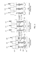
- FIG. 4 illustrates a side view of an adjustable probe system 400 in various different positions, wherein a dual lead screw feature is utilized in accordance with present embodiments.
- the adjustable probe system 400 which includes features similar to those of probe system 200, is shown moving through positions 402, 404, 406, 408, 410, 412, 414, and 416.
- Positions 402, 404, 406, 408, and 410 represent positioning of the system 400 during a deep focal point operation 420.
- Positions 412, 414, and 416 represent transitional operation 422.
- the motor 250 has an additional lead screw, which may be referred to as an upper lead screw 430.
- the upper lead screw 430 is positioned on a back or upper shaft 432, with a smaller lead than the lead screw 254.
- the upper lead screw 430 also has a lead-screw nut, which may be referred to as the upper lead-screw nut 434.
- the upper lead-screw nut 434 spins freely with the upper lead-screw 430. It should be noted that the upper lead-screw nut 434 has some friction torque to avoid inertial driving of the lead screw 430.
- the motor carriage and frame members attached to the transducer 260 are able to slide relative to the probe housing.
- the focus change is achieved by first driving the main slider-crank (lower) lead-screw nut 254 to a position that is closest to the motor 250, which results in an extreme rotational position of the transducer 260.
- a nut engaging mechanism 436 then engages and fixes the upper lead-screw nut 434 to stop it from spinning. This also fixes the lead-screw nut 434 relative to the probe housing and/or probe face 262. As the motor 250 drives in the opposite direction, both lead screws 430 and 254 rotate.
- the motor 250 effectively pulls the motor-carriage and transducer 260 away from the probe face 262, moving the transducer 260 from a deep focal point operation position 420 to a shallow focal point operation position 416.
- the lower lead screw 254 is also rotating, thus causing the lower lead-screw nut 256 to move linearly towards a rotation point, and thus causing the transducer 260 to rotate from its location in position 412 to that in position 416.
- the final orientation of the transducer 260 and the focus change height will depend on the ratio of the lead screw pitches.
- the transducer 260 will move through a 30 degree motion for a 10 mm focal change.
- more vertical motion may be achieved by moving through a higher range of degrees (e.g., 60 degrees of motion).
- FIG. 5 illustrates the steps of moving the system 400 of FIG. 4 from a shallow focal point operation position 416 back to the deep focal point operation position 420 with the dual lead screws 430 and 254.
- the process is similar to that described above with respect to FIG. 4 , but the motor 250 rotates in the opposite direction. Specifically, as illustrated by position 452, the transducer 260 is positioned in the previous final position near a lowest relative position of the driving nut 434. Next, as illustrated by position 454, the upper nut engaging mechanism 436 is engaged to prevent the upper nut 434 from spinning.
- the transducer 260 will tend to rotate counter clockwise, as represented by position 458.
- the final orientation of the transducer 260 and the final vertical position of the motor 250 and transducer 260, as illustrated by position 460, should match initial position of the prior change sequence illustrated in FIG. 4 .
- FIG. 6 illustrates a side view of an adjustable probe system 500 in various different positions, wherein an elevator subsystem 502 is utilized to provide additional vertical movement. Specifically, FIG. 6 illustrates the probe system 500 in positions 504, 506, 508, 510, 512, 514, 516, and 518.
- the system 500 includes components similar to those of the previously described embodiments, which are designated with like reference numerals.
- the system 500 also includes various additional components.
- the system 500 includes an elevator subsystem 502, which includes a thrust bearing 524, a fluid seal 526 positioned within a fluid bulk head 528, an elevator lead screw 530, and an elevator nut assembly 532.
- the elevator subsystem 502 functions to rotate the elevator lead screw 530 in an opposite direction compared to the main lead screw 254 based on the interaction between spur gears 534, which are mechanically engaged and respectively coupled to the elevator lead screw 530 and the main lead screw 254.
- the motor 250 couples to the main lead screw 254 via a spline drive 536, which includes a spline housing 538 and a spline 540.
- the spline drive 536 enables vertical movement of the lead screw 256 relative to the body by facilitating movement of the spline 540 in and out of the spline housing 538.
- the elevator nut assembly 532 rotates in an opposite direction compared to the lead-screw nut 256.
- the elevator nut assembly 532 is normally freely rotating due to drag torque and thus does not change linear position with rotation of the elevator lead screw 530.
- the lead-screw nut 256 is driven into a lower elevator nut 550 of the elevator nut assembly 532, the counter rotating screws and nut traveling in different directions keep the lead-screw nut 256 and the lower elevator nut 550 pressed against each other.
- the elevator nut assembly 532 cannot freely rotate and it moves vertically based on the rotation of the elevator lead screw 530, as represented by position 510.
- the motion of the elevator nut assembly 532 is used to reposition the transducer assembly from a deep focus operation point 570 to a shallow focus operational point 572 and vise-versa.
- the transducer 260 rotates to an extreme position.
- the spline 540 can move into and out of the spline housing 538 to accommodate such vertical position changes.
- the motor 250 does not move because the spline drive 536 is used to couple the output shaft of the motor 250 to the main lead screw 254.
- the lead-screw nut 256 is driven against an upper elevator nut 580 of the elevator nut assembly 532.
- the elevator assembly 532 can no longer freely rotate and thus it moves vertically based on the rotation of the elevator lead screw 530, which is now rotating in a different direction, as generally depicted with regard to the position 518.
- the elevator nut assembly 532 begins transitioning the transducer 260 from the shallow focus operation point 572 back to the deep focus operation point 570.
- FIG. 7 illustrates an adjustable probe assembly 600 that is capable of providing both 4D motion and focus change capability using a crank-rocker slotted system in accordance with present embodiments.
- an input link 602 is driven in an oscillatory motion by a motor 604 such that it is oscillating about a bottom-dead-center point 606 (e.g., +/-45°).
- the motion is transferred from the input link 602 to a transducer link 608 via a pin 610 and slot 612.
- the transducer link 608 thus oscillates about a bottom axis 614 and a transducer 616, which is fixed to the transducer link 608, likewise oscillates.
- the transducer link 608 is disengagably held in position at the bottom axis 614 via a block 620 that is held in place with a spring detent 622 attached to a fixed part of the system (e.g., a wall) and that passes into an opening 624 in the block 620.
- a spring detent 622 attached to a fixed part of the system (e.g., a wall) and that passes into an opening 624 in the block 620.
- the focus position of the transducer 616 can be changed from a deep-focal point operation 650 to a shallow-focal point operation 652 by overdriving the input link 602 towards a top-dead-center position 660, as illustrated by FIG. 8 .
- the driving pin 610 reaches a top end of the slot 612 on the transducer link 608 and continues to drive the transducer link 608.
- This in turn causes the block 620 to decouple from the spring detent 622.
- the driven link 602 continues towards the top-dead-center point 660, the block 620 is guided vertically along a vertical slot 664 towards a top axis point 668, which has a second spring detent 670.
- the spring detent 670 cooperates with the block 620 to fix the axis point at a new height.
- the slot 664 and detents 622, 670 are fixed relative to the probe housing and a probe face 680.
- the driving link 602 can then oscillate about the top-dead-center position 660 for normal 4D motion of the transducer 616, with the transducer 616 in the shallow focus position 652. To change the position back to the deep focus position 650, the driven link 602 is overdriven in the opposite direction, towards the bottom-dead-center point 606.
- fluid may be used to facilitate transmission of waves from the transducer through the probe face 680.
- a sealing bag 682 is attached to the slotted link 608.
- the sealing bag 682 surrounds the transducer 616 in the two positions illustrated by FIGS. 7 and 8 for proper fluid coupling of the transducer 616 to the probe face 680.
- the sealing bag 682 may be fixed to the probe face 680 and the slotted link 602 to allow for variable fluid standoff for acoustic coupling.
Landscapes
- Health & Medical Sciences (AREA)
- Life Sciences & Earth Sciences (AREA)
- Public Health (AREA)
- Nuclear Medicine, Radiotherapy & Molecular Imaging (AREA)
- Radiology & Medical Imaging (AREA)
- Biomedical Technology (AREA)
- Animal Behavior & Ethology (AREA)
- General Health & Medical Sciences (AREA)
- Engineering & Computer Science (AREA)
- Veterinary Medicine (AREA)
- Biophysics (AREA)
- Physics & Mathematics (AREA)
- Pathology (AREA)
- Heart & Thoracic Surgery (AREA)
- Medical Informatics (AREA)
- Molecular Biology (AREA)
- Surgery (AREA)
- Ultra Sonic Daignosis Equipment (AREA)
- Surgical Instruments (AREA)
Abstract
Description
- The subject matter disclosed herein relates to ultrasound probes that may be utilized for diagnostic and/or therapeutic purposes. More particularly, present embodiments are directed to systems and methods that facilitate adjustment of a focus depth of an ultrasound probe between multiple positions while maintaining acoustic coupling.
- The term ultrasound generally refers to cyclic sound pressure that has a frequency in a range that is higher than the upper limit of human hearing. A typical ultrasound frequency may include 1 to 20 megahertz. Ultrasound is frequently used for imaging purposes. For example, ultrasound is used in ultrasonography, which is a medical imaging technique that emits high frequency sound waves into a patient's body and detects echoes of the sound waves to produce images of features internal to the patient's body (e.g., blood flow images and intrauterine images). However, ultrasound may also be utilized to perform functions. For example, ultrasound may be utilized to facilitate removal of a buildup of foreign matter from a surface or for therapeutic purposes (e.g., stimulating a damaged muscle).
- While there are numerous uses for ultrasound, a representative example may include a medical imaging application. In a typical ultrasound imaging application, sound waves are emitted into a patient's body from a probe and are reflected back to the probe when they hit boundaries. For example, some waves may reflect back to the probe upon reaching a boundary between fluid and tissue and other waves may reflect back to the probe upon reaching a boundary between tissue and bone. The probe detects the reflected waves and relays them to a monitor that utilizes the speed of the ultrasound and the time required to detect the reflected wave relative to the time of emission to calculate the distance from the probe to the reflecting surface. The distances and intensities of the detected waves may then be displayed to provide an image of the observed tissue. Relatively dense tissue may be distinguished from less dense tissue based on a difference in intensity because more dense tissue may reflect more ultrasound waves than less dense tissue.
- Many ultrasound probes include an elevational lens that focuses ultrasound energy at a specific and fixed distance from a transducer. However, typical ultrasound images show a range of depths, and it is now recognized that since the depth at which the transducer is focused may not be consistent with a desired image, it may be desirable to adjust the depth at which the transducer is focused.
- In one embodiment a multi-focus probe includes a motor communicatively coupled with a lead screw and configured to turn the lead screw about a lengthwise axis of the lead screw, wherein the lead screw includes a length having threads. The probe also includes a lead-screw nut positioned about the lead screw such that the lead-screw nut engages the threads and such that the lead-screw nut and the lead screw can move relative to one another via the threads, a transducer configured to move vertically with the lead screw, and an enclosure surrounding the transducer, wherein the enclosure includes a probe face configured to hold fluid and engage a wave emission target such that waves from the transducer can enter the target. Further, the probe includes a capture feature capable of engaging the lead-screw nut such that the lead-screw nut is vertically fixed relative to the probe face and such that the lead screw moves away from the probe face when rotating within the lead-screw nut in a first direction and moves toward the probe face when rotating within the lead-screw nut in a second direction opposite to the first direction while the lead-screw nut is engaged by the capture feature.
- In one embodiment, a method includes rotating a lead screw with a motor, wherein the lead screw is at least partially positioned within a probe housing including a probe face, causing a lead-screw nut to travel along threads of the lead screw based on rotation of the lead screw such that the lead-screw nut moves vertically relative to the probe face, and engaging the lead-screw nut with a capture feature such that the lead screw-nut is in a fixed position relative to the probe face and continuing to rotate the lead screw such that the lead screw moves vertically relative to the probe face into a different position thus repositioning a transducer that is coupled to an assembly that moves with the lead screw.
- In one embodiment, a multi-focus probe includes a driven link coupled to a housing at a first end via hinged coupling such that the driven link is capable of rotating about the hinged coupling, a transducer link coupled with the driven link via a slot in a first end of the transducer link and a pin in a second end of the driven link, a transducer coupled to the transducer link at second end of the transducer link opposite to the first end of the transducer link, and a motor configured to rotate the driven link about the hinged coupling.
- These and other features, aspects, and advantages of the present invention will become better understood when the following detailed description is read with reference to the accompanying drawings in which like characters represent like parts throughout the drawings, wherein:
-
FIG. 1 is a profile view of an ultrasound probe emitting an ultrasound beam from a transducer at two different positions within a probe housing in accordance with an embodiment; -
FIG. 2 illustrates a side view of an adjustable probe system in various different positions in accordance with an embodiment; -
FIG. 3 illustrates a side view of an adjustable probe system in various different positions, wherein a nut capture feature is utilized in accordance with an embodiment; -
FIG. 4 illustrates a side view of an adjustable probe system in various different positions, wherein a dual lead screw feature is utilized in accordance with an embodiment; -
FIG. 5 illustrates the steps of moving the system ofFIG. 4 from a shallow focal point operation position to a deep focal point operation position with dual lead screws in accordance with an embodiment; -
FIG. 6 illustrates a side view of an adjustable probe system in various different positions, wherein an elevator subsystem is utilized to provide additional vertical movement in accordance with an embodiment; and -
FIGS. 7 and 8 illustrate an adjustable probe assembly that is capable of providing both 4D motion and focus change capability using a crank-rocker slotted system in accordance with an embodiment. - One or more specific embodiments of the present invention will be described below. In an effort to provide a concise description of these embodiments, all features of an actual implementation may not be described in the specification. It should be appreciated that in the development of any such actual implementation, as in any engineering or design project, numerous implementation-specific decisions must be made to achieve the developers' specific goals, such as compliance with system-related and business-related constraints, which may vary from one implementation to another. Moreover, it should be appreciated that such a development effort might be complex and time consuming, but would nevertheless be a routine undertaking of design, fabrication, and manufacture for those of ordinary skill having the benefit of this disclosure.
- When introducing elements of various embodiments of the present invention, the articles "a," "an," "the," and "said" are intended to mean that there are one or more of the elements. The terms "comprising," "including," and "having" are intended to be inclusive and mean that there may be additional elements other than the listed elements.
- Technical effects of the invention include providing the functionality of more than one ultrasound probe within a single unit by enabling the probe to be vertically adjusted into different positions while maintaining acoustic coupling. The varying vertical positions of the probe facilitate movement of the focus depth of the probe throughout a target (e.g., tissue) such that the functionality of multiple different probes may be achieved. Relative to conventional single probe solutions, present embodiments may provide improved image quality or treatment efficacy for both superficial and deep features by providing a multi-focus probe. With regard to diagnostic (e.g., imaging) and therapeutic (e.g., muscle stimulation) functions, present embodiments may provide flexibility in the patient population on which the probe may be utilized because the multi-focus probe may be adjusted for different focus depths corresponding to different patient types. Further, such a multi-focus functionality may facilitate tailored treatment of patients that may improve efficacy. For example, by enabling an adjustable focus depth, present embodiments may facilitate an increase in success rates in imaging applications such as catheter guidance procedures.
- Present embodiments are generally directed to a system and method for adjustably focusing an ultrasound probe at different depths within a target. More particularly, the present disclosure provides systems and methods whereby the location of the focus of an ultrasound transducer can be varied in depth by mechanically shifting the position of the transducer within a probe housing. In present embodiments, the transducer may have a fixed focus, which means that the focus of emitted ultrasound is in a fixed location relative to the transducer itself, not relative to the probe housing. Accordingly, in present embodiments, the distance between the transducer and a contact surface of the probe housing (i.e., the portion of the probe that provides acoustic coupling between the probe and the target) can be changed either automatically or by a user to place the focus of the transducer in a particular region. For example, the depth of focus in a patient's tissue may be changed by moving the transducer relative to the contact surface to place the focus of the ultrasound waves in a diagnostic or therapeutic region of interest.
-
FIG. 1 illustrates a profile view of anultrasound probe 100 emitting anultrasound beam 102 from atransducer 104 at two different positions within aprobe housing 106 in accordance with present embodiments. Theultrasound probe 100 is positioned such that aface 118 of theprobe 100 isadjacent tissue 108, which includes various items ofinterest first position 120 of thetransducer 104 relative to theprobe housing 106, thetransducer 104 is positioned away from acontact surface 116 between theface 118 of theprobe 100 and thetissue 108. - However, the
probe housing 106 is filled with fluid such that acoustic coupling is maintained between thetransducer 104 and the tissue in thefirst position 120 because the fluid fills the void provided when thetransducer 104 is moved into thefirst position 120 from asecond position 122. The fluid allows transmission of ultrasound waves between theface 118 and thetransducer 104. In thesecond position 122, thetransducer 104 is positioned near or adjacent theface 118, which is the portion of theprobe housing 100 contacting thetissue 108. - The
first position 120 and thesecond position 122 each provide different focus points within thetissue 108. Thus, eachposition tissue 108. For example, an optimal imaging range for thefirst position 120 is indicated byreference numeral 126, and the optimal imaging range for thesecond position 122 is indicated byreference numeral 130. In view of the differing optimal imaging ranges, eachposition interest transducer 104 does not coincide with the region of interest, resulting image quality may suffer. However, more and better information may be provided for a region of interest if the focus depth falls within that region. For example, thefirst position 120 may provide a clearer and/or better defined image of theitem 110 than theitems second position 122 may provide a clearer and/or better defined image ofitem 112 thanitems -
FIG. 2 illustrates a side view of anadjustable probe system 200 in various different positions in accordance with present embodiments. Specifically, theadjustable probe system 200 includes a positioning mechanism that is shown moving throughpositions Positions system 200 during a deepfocal point operation 230.Position 208 represents a transition from deep operation toshallow operation 232.Positions system 200 during a shallowfocal point operation 234.Positions deep operation 236. These positions will be discussed in further detail below as they relate to the functions of thesystem 200 and its components. - Among other things, the
system 200 includes a motor ordrive mechanism 250, afluid shaft seal 252, alead screw 254, a lead-screw nut 256, acoupler link 258, a transducer 260 (e.g., a transducer array), aprobe face 262, a pivot joint 264, anupper end stop 266, and alower end stop 268. For instructive purposes, anultrasound beam 270 emitted by theprobe system 200 is also illustrated in the various positions of thesystem 200. Thesystem 200 also includes a body (not shown). For example, the body may contain themotor 250 and/or include features that cooperate with thefluid shaft seal 252 to contain fluid about thetransducer 260. In the embodiment illustrated inFIG. 2 and other embodiments, the fluid is contained in the interior portion of the probe handle so that the fluid can provide coupling between thetransducer 260 and theprobe face 262. While not explicitly shown in all cases, the fluid may be retained in the lower portion of the probe using a bulkhead internal to the probe. A shaft seal would be utilized around the lead screw shaft. Additionally, motor carriage / array assembly frame members extending from themotor 250 to the pivot joint 264 would also include some manner of seal, either through shaft sealing methods (contact seals) or flexible membrane seals (bag seals). - In accordance with the present disclosure, a positioning mechanism including various different mechanical features may be utilized to adjust the field of view and focus depth of the ultrasound energy provided by the
ultrasound beam 270 of thetransducer 260. Oscillating thetransducer 260 about the pivot joint 264, as illustrated by the movement between positions 202-206 and between positions 210-214, may improve the field of view or coverage of thetransducer 260. For imaging applications, oscillating the transducer enables the acquisition of a large three-dimensional field of view, without having to move thesystem 200 itself. In cases where oscillation of thetransducer 260 is sufficiently fast (e.g., greater than approximately 7Hz), a real-time volumetric image (4D) may be acquired and rendered. For therapy applications, oscillating the transducer enables the ultrasound therapy to be applied to a greater tissue volume without repositioning theentire system 200. - One method for achieving oscillatory motion of the
transducer 260 in a compact probe handle is to use a slider-crank based drive system. Thetransducer 260 is equivalent to the driven link that is coupled to the slider. The slider or driving link is the lead-screw nut 256. The lead-screw nut 256 travels in a linear manner and the direction of the motion is based on the direction of rotation of thelead screw 254 that is driven by the motor 250 (e.g., a servomotor or stepper). Driving themotor 250 in a particular direction for a given time or to a given rotational position turns thelead screw 254 in the same manner. The rotation of thelead screw 254 causes the lead-screw nut 256 to advance along thelead screw 254 in a linear manner so long as the lead-screw nut 256 cannot rotate relative to themotor 250. The lead-screw nut 256 is prevented from rotating with respect to themotor 250 throughpin joints 280 with thecoupler link 258 that is pin jointed to thetransducer 260 which is pin jointed to the body (e.g., motor frame / carriage housing). It should be noted that pin joints are indicated byreference numeral 280 and the pin joints 280 have parallel axes in the illustrated embodiment. The pins joints 280 are also parallel to thepivot j oint 264. The pin joints 280 function as hinges such that they hingedly couple the indicated features. The linear motion of the lead-screw nut 256 is transmitted to thetransducer 260 through thecoupler link 258, which is coupled to thetransducer 260 at a position that is not at the transducer's rotational axis. The linear motion of the lead-screw nut 256 thus imparts a rotational motion of thetransducer 260 about the axis-of-rotation of thetransducer 260. Thus, an oscillatory motion of the motor output also causes a rotational oscillatory motion of thetransducer 260, as represented bypositions - The
system 200 provides both 4D motion and the capability to change focus using only one actuator to achieve both actions. Indeed, in accordance with present embodiments, thesystem 200 may utilize the slider-crank mechanism to create the 4D motion oscillation of thetransducer 260, as discussed above. Further, the system may achieve focus change by repositioning thetransducer 260 with respect to the probe face 262 (e.g., linearly moving the pivot joint 264 relative to the probe face 262). This may be achieved by driving the lead-screw nut 256 against the lower end-stop 268, which is a capture feature fixed relative to the probe (e.g., coupled to the housing via a pivot joint). With the lead-screw nut 256 abutting the lower end-stop 268, themotor 250 continues driving thelead screw 254 in the same rotational direction. A motor carriage and frame members attached to thetransducer 260 are able to slide relative to theprobe housing 260, as represented by the movement of themotor 250 illustrated betweenpositions lead screw 254 then causes the motor carriage (e.g., motor 250) and thetransducer 260 to move away from theprobe face 262, transitioning (as represented by position 208) from deepfocal point operation 230 to shallowfocal point operation 234. During this transition, the transducer rotates to an extreme position. With the carriage in its new position relative to theprobe face 262, themotor 250 can then drive thelead screw 254 to oscillate thetransducer 260 and achieve 4D motion, as represented by positions 210-214. To return to the startingposition 202, thelead screw 254 over-drives the lead-screw nut 256 against the upper end-stop 266, and in a similar manner causes the motor carriage (e.g., motor 250) to move closer to theprobe face 262 such that thetransducer 260 returns to the deepfocal point operation 230. In accordance with present embodiments, no additional actuation other than the single motor 250 (or stepper) may be needed to achieve this 4D motion and focus change capability. To maximize the overdrive range-of-motion (i.e., the distance between the deep focalpoint operation position 230 and the shallow focal point operation position 234), the curved orbent coupler link 258 can be used. Also, it should be noted that it may be beneficial to utilize friction detents (or magnets) at the extreme positions to hold the motor-carriage/array assembly in place. -
FIG. 3 illustrates a side view of an adjustable probe system 300 in various different positions, wherein anut capture feature 302 is utilized in accordance with present embodiments. Specifically, the adjustable probe system 300, which includes features similar to those ofprobe system 200, is shown moving throughpositions Positions focal point operation 322.Positions focal point operation 324.Positions focal point operation 326. Transitions between the operation depths are facilitated by thenut capture mechanism 302. In some embodiments, thenut capture mechanism 302 includes two separate actuators positioned atdifferent locations nut capture mechanism 302 may include a single actuator that cooperates to provide resistance at bothlocations screw nut 256 depending on the position of the lead-screw nut 256. - The system 300 provides both 4D motion and focus change capability using only a
motor 250 and two actuators to achieve both actions. The 4D motion oscillation of the transducer may be achieved through the slider-crank mechanism as discussed above with regard toFIG. 2 . Focus change is achieved by driving the lead-screw nut 256 to a specific position and engaging thenut capture feature 302 that captures the lead-screw nut 256 and holds it fixed relative to the probe housing. With the lead-screw nut 256 captured, themotor 250 continues driving thelead screw 254 in the same rotational direction. Thus, the motor carriage and frame members attached to thetransducer 260 slide relative to the probe housing. The driving action of thelead screw 254 then causes the motor carriage andtransducer 260 to move away from theprobe face 262, transitioning from deepfocal point operation 322 to a shallower or mid-depthfocal point operation 324. During the transition motion, the transducer rotates within the normal range-of-motion. At this point, thenut capture mechanism 302 releases the lead-screw nut 256 to allow for normal 4D operation. Thenut capture mechanism 302 may also simultaneously engage the motor-carriage/array assembly to prevent any relative motion with the probe housing. As shown inFIG. 3 , with a nut-capture system 302 in multiple locations, such aslocation 330 andlocation 332, it is possible to increase the distance between the deep-focal point 322 and the shallow-focal point 326 and have intermediate operational points, such as the mid-depth focal pointoperational point 324. To return to the deep focalpoint operation position 322, such that the transducer is at its closest operating point relative to theprobe face 262, the procedure discussed above with regard to system 300 may be reversed. Again, it may be beneficial to utilize friction detents (or magnets) at the extreme and intermediate positions to hold the motor-carriage/array assembly in place. Alternatively, it may be possible to utilize the same actuator that engages the nut in one state to engage the motor-carriage/array assembly in the other state. In such an embodiment, the actuator would be fixed relative to the probe housing and theprobe face 262. -
FIG. 4 illustrates a side view of anadjustable probe system 400 in various different positions, wherein a dual lead screw feature is utilized in accordance with present embodiments. Specifically, theadjustable probe system 400, which includes features similar to those ofprobe system 200, is shown moving throughpositions Positions system 400 during a deepfocal point operation 420.Positions transitional operation 422. - In the embodiment illustrated by
FIG. 4 , themotor 250 has an additional lead screw, which may be referred to as anupper lead screw 430. Theupper lead screw 430 is positioned on a back orupper shaft 432, with a smaller lead than thelead screw 254. Theupper lead screw 430 also has a lead-screw nut, which may be referred to as the upper lead-screw nut 434. During normal 4D motions, the upper lead-screw nut 434 spins freely with the upper lead-screw 430. It should be noted that the upper lead-screw nut 434 has some friction torque to avoid inertial driving of thelead screw 430. The motor carriage and frame members attached to thetransducer 260 are able to slide relative to the probe housing. The focus change is achieved by first driving the main slider-crank (lower) lead-screw nut 254 to a position that is closest to themotor 250, which results in an extreme rotational position of thetransducer 260. Anut engaging mechanism 436 then engages and fixes the upper lead-screw nut 434 to stop it from spinning. This also fixes the lead-screw nut 434 relative to the probe housing and/orprobe face 262. As themotor 250 drives in the opposite direction, both leadscrews upper lead screw 430 rotates with the upper lead-screw nut 434 fixed, themotor 250 effectively pulls the motor-carriage andtransducer 260 away from theprobe face 262, moving thetransducer 260 from a deep focalpoint operation position 420 to a shallow focalpoint operation position 416. Simultaneously, thelower lead screw 254 is also rotating, thus causing the lower lead-screw nut 256 to move linearly towards a rotation point, and thus causing thetransducer 260 to rotate from its location inposition 412 to that inposition 416. The final orientation of thetransducer 260 and the focus change height will depend on the ratio of the lead screw pitches. For example, with a lower lead of 3.18 mm and an upper lead of 12.7 mm (a lead screw ratio of 4), thetransducer 260 will move through a 30 degree motion for a 10 mm focal change. In some embodiments, more vertical motion may be achieved by moving through a higher range of degrees (e.g., 60 degrees of motion). -
FIG. 5 illustrates the steps of moving thesystem 400 ofFIG. 4 from a shallow focalpoint operation position 416 back to the deep focalpoint operation position 420 with the dual lead screws 430 and 254. The process is similar to that described above with respect toFIG. 4 , but themotor 250 rotates in the opposite direction. Specifically, as illustrated byposition 452, thetransducer 260 is positioned in the previous final position near a lowest relative position of the drivingnut 434. Next, as illustrated byposition 454, the uppernut engaging mechanism 436 is engaged to prevent theupper nut 434 from spinning. As themotor 250 and lead-screw nut 256 move upwards relative to lead-screw 254 (as illustrated by arrow 456), thetransducer 260 will tend to rotate counter clockwise, as represented byposition 458. The final orientation of thetransducer 260 and the final vertical position of themotor 250 andtransducer 260, as illustrated byposition 460, should match initial position of the prior change sequence illustrated inFIG. 4 . -
FIG. 6 illustrates a side view of anadjustable probe system 500 in various different positions, wherein anelevator subsystem 502 is utilized to provide additional vertical movement. Specifically,FIG. 6 illustrates theprobe system 500 inpositions - The
system 500 includes components similar to those of the previously described embodiments, which are designated with like reference numerals. Thesystem 500 also includes various additional components. For example, thesystem 500 includes anelevator subsystem 502, which includes athrust bearing 524, afluid seal 526 positioned within afluid bulk head 528, anelevator lead screw 530, and anelevator nut assembly 532. Theelevator subsystem 502 functions to rotate theelevator lead screw 530 in an opposite direction compared to themain lead screw 254 based on the interaction between spur gears 534, which are mechanically engaged and respectively coupled to theelevator lead screw 530 and themain lead screw 254. Themotor 250 couples to themain lead screw 254 via aspline drive 536, which includes aspline housing 538 and aspline 540. Thespline drive 536 enables vertical movement of thelead screw 256 relative to the body by facilitating movement of thespline 540 in and out of thespline housing 538. - In operation, the
elevator nut assembly 532 rotates in an opposite direction compared to the lead-screw nut 256. Theelevator nut assembly 532 is normally freely rotating due to drag torque and thus does not change linear position with rotation of theelevator lead screw 530. However, when the lead-screw nut 256 is driven into alower elevator nut 550 of theelevator nut assembly 532, the counter rotating screws and nut traveling in different directions keep the lead-screw nut 256 and thelower elevator nut 550 pressed against each other. Thus, theelevator nut assembly 532 cannot freely rotate and it moves vertically based on the rotation of theelevator lead screw 530, as represented byposition 510. The motion of theelevator nut assembly 532 is used to reposition the transducer assembly from a deepfocus operation point 570 to a shallow focusoperational point 572 and vise-versa. During this transition, thetransducer 260 rotates to an extreme position. As indicated above, thespline 540 can move into and out of thespline housing 538 to accommodate such vertical position changes. Indeed, in the illustrated embodiment ofFIG. 6 , themotor 250 does not move because thespline drive 536 is used to couple the output shaft of themotor 250 to themain lead screw 254. Again, it may be desirable to utilize friction detents (or magnets) at the extreme and intermediate positions to hold the motor-carriage/array assembly in place. This method enables a larger focus position change as compared to the overdrive method alone. - In order to return the system to the deep
focus point position 570, the lead-screw nut 256 is driven against anupper elevator nut 580 of theelevator nut assembly 532. As was the case when thelower elevator nut 550 was pressed against the lead-screw nut 256, theelevator assembly 532 can no longer freely rotate and thus it moves vertically based on the rotation of theelevator lead screw 530, which is now rotating in a different direction, as generally depicted with regard to theposition 518. As a result, theelevator nut assembly 532 begins transitioning thetransducer 260 from the shallowfocus operation point 572 back to the deepfocus operation point 570. -
FIG. 7 illustrates anadjustable probe assembly 600 that is capable of providing both 4D motion and focus change capability using a crank-rocker slotted system in accordance with present embodiments. In this embodiment, aninput link 602 is driven in an oscillatory motion by amotor 604 such that it is oscillating about a bottom-dead-center point 606 (e.g., +/-45°). The motion is transferred from theinput link 602 to atransducer link 608 via apin 610 andslot 612. Thetransducer link 608 thus oscillates about abottom axis 614 and a transducer 616, which is fixed to thetransducer link 608, likewise oscillates. Thetransducer link 608 is disengagably held in position at thebottom axis 614 via ablock 620 that is held in place with aspring detent 622 attached to a fixed part of the system (e.g., a wall) and that passes into anopening 624 in theblock 620. - The focus position of the transducer 616 can be changed from a deep-
focal point operation 650 to a shallow-focal point operation 652 by overdriving theinput link 602 towards a top-dead-center position 660, as illustrated byFIG. 8 . Assuming a sufficient torque margin, the drivingpin 610 reaches a top end of theslot 612 on thetransducer link 608 and continues to drive thetransducer link 608. This in turn causes theblock 620 to decouple from thespring detent 622. As the drivenlink 602 continues towards the top-dead-center point 660, theblock 620 is guided vertically along avertical slot 664 towards atop axis point 668, which has asecond spring detent 670. Thespring detent 670 cooperates with theblock 620 to fix the axis point at a new height. Theslot 664 anddetents probe face 680. The drivinglink 602 can then oscillate about the top-dead-center position 660 for normal 4D motion of the transducer 616, with the transducer 616 in theshallow focus position 652. To change the position back to thedeep focus position 650, the drivenlink 602 is overdriven in the opposite direction, towards the bottom-dead-center point 606. - It should be noted that, as with the previously described embodiments, fluid may be used to facilitate transmission of waves from the transducer through the
probe face 680. In the illustrated embodiment, a sealingbag 682 is attached to the slottedlink 608. The sealingbag 682 surrounds the transducer 616 in the two positions illustrated byFIGS. 7 and 8 for proper fluid coupling of the transducer 616 to theprobe face 680. The sealingbag 682 may be fixed to theprobe face 680 and the slottedlink 602 to allow for variable fluid standoff for acoustic coupling. - This written description uses examples to disclose the invention, including the best mode, and also to enable any person skilled in the art to practice the invention, including making and using any devices or systems and performing any incorporated methods. The patentable scope of the invention is defined by the claims, and may include other examples that occur to those skilled in the art. Such other examples are intended to be within the scope of the claims if they have structural elements that do not differ from the literal language of the claims, or if they include equivalent structural elements with insubstantial differences from the literal languages of the claims.
- Various aspects and embodiments of the present invention are defined by the following numbered clauses:
- 1. A multi-focus ultrasound probe, comprising:
- an enclosure surrounding a transducer, wherein the enclosure includes a probe face configured to engage a wave emission target such that waves from the transducer can enter the target via the face;
- a positioning mechanism configured to oscillate the transducer about an axis and configured to adjust a focal point operation depth of the transducer by moving the transducer towards or away from the probe face; and
- a fluid contained within the enclosure, wherein the fluid fills space between the transducer and the probe face.
- 2. The multi-focus ultrasound probe of clause 1, wherein the positioning mechanism is configured to move the axis linearly toward or away from the probe housing.
- 3. The multi-focus ultrasound probe of clause 1 or
clause 2, wherein a drive mechanism is communicatively coupled with the positioning mechanism to drive the transducer towards or away from the probe face. - 4. The multi-focus ultrasound probe of any preceding clause, wherein the drive mechanism is configured to drive the positioning mechanism to oscillate the transducer about the axis.
- 5. The multi-focus ultrasound probe of any preceding clause, comprising a drive mechanism configured to drive a slider along a linear component of the positioning mechanism such that a link coupled to a side of the transducer causes the transducer to pivot about the axis of the transducer.
- 6. The multi-focus ultrasound probe of any preceding clause, wherein the slider is a lead-screw nut coupled to a lead screw such that the lead-screw nut engages threads of the lead screw and rotation of the lead screw when the lead-screw nut is not rotating moves the lead-screw nut along a length of the lead screw via the threads.
- 7. The multi-focus ultrasound probe of any preceding clause, comprising a capture feature capable of engaging the lead-screw nut such that the lead-screw nut is vertically fixed relative to the probe face and such that the axis moves away from the probe face when the lead screw is rotating in a first direction and toward the probe face when the lead screw is rotating in a second direction opposite the first direction while the lead-screw nut is engaged by the capture feature.
- 8. The multi-focus ultrasound probe of any preceding clause, wherein the lead-screw nut comprises a receptacle and the capture feature comprises an actuator configured to engage the receptacle.
- 9. The multi-focus ultrasound probe of any preceding clause, wherein the capture feature comprises a pair of pegs located in different positions along a length of the lead screw.
- 10. The multi-focus ultrasound probe of any preceding clause, wherein the positioning mechanism comprises:
- a driven link capable of rotating about a hinged coupling at a first end of the driven link;
- a transducer link coupled with the driven link via a slot in a first end of the transducer link and a pin in a second end of the driven link, wherein a second end of the transducer link is coupled to the transducer; and
- a motor configured to rotate the driven link about the hinged coupling.
- 11. The multi-focus ultrasound probe of any preceding clause, wherein the positioning mechanism comprises a first lead screw and a second lead screw communicatively coupled with a dual-shaft motor, a first lead-screw nut engaged with the first lead screw such that the lead-screw nut engages threads of the first lead screw and rotation of the first lead screw when the lead-screw nut is not rotating moves the lead-screw nut along a length of the first lead screw via the threads, and a second lead-screw is engaged with the second lead screw such that the second lead-screw nut is capable of free spinning with the second lead screw unless engaged by a secondary capture feature coupled to the enclosure.
- 12. A multi-focus ultrasound probe, comprising:
- a motor communicatively coupled with a lead screw and configured to turn the lead screw about a lengthwise axis of the lead screw, wherein the lead screw includes a length having threads;
- a lead-screw nut positioned about the lead screw such that the lead-screw nut engages the threads and such that the lead-screw nut and the lead screw can move relative to one another via the threads;
- a transducer configured to move vertically with the lead screw;
- an enclosure surrounding the transducer, wherein the enclosure includes a probe face configured to hold fluid and engage a wave emission target such that waves from the transducer can enter the target; and
- a capture feature capable of engaging the lead-screw nut such that the lead-screw nut is vertically fixed relative to the probe face and such that the lead screw moves away from the probe face when rotating within the lead-screw nut in a first direction and moves toward the probe face when rotating within the lead-screw nut in a second direction opposite to the first direction while the lead-screw nut is engaged by the capture feature.
- 13. The multi-focus ultrasound probe of any preceding clause, wherein the capture feature includes a first end stop coupled to the enclosure between the motor and the lead-screw nut such that the lead-screw nut engages the first end stop when the lead-screw nut passes along the lead screw a first distance toward the motor, and a second end stop coupled to the enclosure between the probe face and the lead-screw nut such that the lead-screw nut engages the second end stop when the lead-screw nut passes along the lead screw a second distance toward the probe face.
- 14. The multi-focus ultrasound probe of any preceding clause, wherein the motor comprises a dual-shaft motor and the dual-shaft motor communicatively couples with a secondary lead screw on a side of the dual-shaft motor opposite the lead screw.
- 15. The multi-focus ultrasound probe of any preceding clause, wherein the secondary lead screw is coupled to a secondary lead-screw nut capable of free spinning with the secondary lead screw unless engaged by a secondary capture feature coupled to the enclosure.
- 16. The multi-focus ultrasound probe of any preceding clause, wherein the capture feature includes an elevator nut assembly configured to move relative to the probe face based on mechanical coupling of an elevator subassembly to the motor.
- 17. The multi-focus ultrasound probe of any preceding clause, comprising a coupler link that hingedly attaches to the lead-screw nut and hingedly attaches to the transducer to provide a coupling between the transducer and the lead-screw nut.
- 18. A method, comprising:
- rotating a lead screw with a motor, wherein the lead screw is at least partially positioned within an ultrasound probe housing including a probe face;
- causing a lead-screw nut to travel along threads of the lead screw based on rotation of the lead screw such that the lead-screw nut moves vertically relative to the probe face; and
- engaging the lead-screw nut with a capture feature such that the lead screw-nut is in a fixed position relative to the probe face and continuing to rotate the lead screw such that the lead screw moves vertically relative to the probe face into a different position thus repositioning an ultrasound transducer that is coupled to an assembly that moves with the lead screw.
- 19. The method of clause 18, wherein engaging the lead-screw nut with a capture feature comprises pressing an end of the lead-screw nut against a fixed end stop or an actuator that is coupled with the ultrasound probe.
- 20. The method of clause 18 or clause 19, wherein engaging the lead-screw nut with a capture feature comprises pressing an end of the lead-screw nut against an elevator nut traveling in an opposite direction relative to the movement of the lead-screw nut along the lead screw.
- 21. The method of any of clauses 18 to 22, comprising rotating a secondary lead screw that is coupled with a normally free spinning secondary nut with the motor on a side of the motor opposite to the lead screw.
- 22. A multi-focus ultrasound probe, comprising:
- a driven link coupled to a housing at a first end via hinged coupling such that the driven link is capable of rotating about the hinged coupling;
- a transducer link coupled with the driven link via a slot in a first end of the transducer link and a pin in a second end of the driven link;
- a transducer coupled to the transducer link at second end of the transducer link opposite to the first end of the transducer link; and
- a motor configured to rotate the driven link about the hinged coupling.
- 23. The multi-focus ultrasound probe of any preceding clause, wherein at least a portion of the transducer link and all of the transducer are contained by a sealing bag and a probe face.
- 24. The multi-focus ultrasound probe of any preceding clause, wherein the transducer is coupled with a block that is positioned with a vertical channel such that when the driven link is below the hinged coupling the transducer is positioned along the channel farther away from the hinged coupling than when the driven link is above the hinged coupling.
- 25. The multi-focus ultrasound probe of any preceding clause, comprising a first detent positioned along the channel and configured to engage the block when the driven link is above the hinged coupling.
Claims (10)
- A multi-focus ultrasound probe (100), comprising:an enclosure (106) surrounding a transducer (104), wherein the enclosure (106) includes a probe face (118) configured to engage a wave emission target such that waves from the transducer (104) can enter the target via the face (118);a positioning mechanism (200) configured to oscillate the transducer (104) about an axis and configured to adjust a focal point operation depth of the transducer (104) by moving the transducer (104) towards or away from the probe face (118); anda fluid contained within the enclosure (106), wherein the fluid fills space between the transducer (104) and the probe face (118).
- The multi-focus ultrasound probe (100) of claim 1, wherein the positioning mechanism (200) is configured to move the axis linearly toward or away from the probe housing (106).
- The multi-focus ultrasound probe (100) of claim 1 or claim 2, wherein a drive mechanism (250) is communicatively coupled with the positioning mechanism (200) to drive the transducer (104) towards or away from the probe face (118).
- The multi-focus ultrasound probe (100) of any preceding claim, wherein the drive mechanism (250) is configured to drive the positioning mechanism (200) to oscillate the transducer (104) about the axis.
- The multi-focus ultrasound probe (100) of any preceding claim, comprising a drive mechanism (250) configured to drive a slider (256) along a linear component of the positioning mechanism (200) such that a link coupled to a side of the transducer (104) causes the transducer (104) to pivot about the axis of the transducer (104).
- The multi-focus ultrasound probe (100) of any preceding claim, wherein the slider (256) is a lead-screw nut (256) coupled to a lead screw (254) such that the lead-screw nut (256) engages threads of the lead screw (254) and rotation of the lead screw (254) when the lead-screw nut (246) is not rotating moves the lead-screw nut (256) along a length of the lead screw (254) via the threads.
- The multi-focus ultrasound probe (100) of any preceding claim, comprising a capture feature (268) capable of engaging the lead-screw nut (256) such that the lead-screw nut (256) is vertically fixed relative to the probe face (118) and such that the axis moves away from the probe face (118) when the lead screw (254) is rotating in a first direction and toward the probe face (118) when the lead screw (254) is rotating in a second direction opposite the first direction while the lead-screw nut (256) is engaged by the capture feature (268).
- The multi-focus ultrasound probe (100) of any preceding claim, wherein the lead-screw nut (256) comprises a receptacle and the capture feature (268) comprises an actuator configured to engage the receptacle.
- The multi-focus ultrasound probe (100) of any preceding claim, wherein the capture feature (268) comprises a pair of pegs located in different positions along a length of the lead screw (254).
- The multi-focus ultrasound probe (100) of any preceding claim, wherein the positioning mechanism (200) comprises:a driven link (602) capable of rotating about a hinged coupling at a first end of the driven link (602);a transducer link coupled with the driven link via a slot in a first end of the transducer link (608) and a pin (610) in a second end of the driven link (602), wherein a second end of the transducer link (608) is coupled to the transducer (616); anda motor (250) configured to rotate the driven link (6020 about the hinged coupling.
Applications Claiming Priority (1)
| Application Number | Priority Date | Filing Date | Title |
|---|---|---|---|
| US12/873,026 US8409102B2 (en) | 2010-08-31 | 2010-08-31 | Multi-focus ultrasound system and method |
Publications (2)
| Publication Number | Publication Date |
|---|---|
| EP2422708A1 true EP2422708A1 (en) | 2012-02-29 |
| EP2422708B1 EP2422708B1 (en) | 2017-06-21 |
Family
ID=44719304
Family Applications (1)
| Application Number | Title | Priority Date | Filing Date |
|---|---|---|---|
| EP11178939.2A Active EP2422708B1 (en) | 2010-08-31 | 2011-08-25 | Multi-focus ultrasound system |
Country Status (4)
| Country | Link |
|---|---|
| US (1) | US8409102B2 (en) |
| EP (1) | EP2422708B1 (en) |
| JP (1) | JP5771095B2 (en) |
| CA (1) | CA2749465A1 (en) |
Cited By (4)
| Publication number | Priority date | Publication date | Assignee | Title |
|---|---|---|---|---|
| WO2014140557A1 (en) * | 2013-03-13 | 2014-09-18 | University Of Newcastle Upon Tyne | Ultrasound imaging apparatus |
| EP3578227A4 (en) * | 2017-01-31 | 2020-01-22 | Jong Chul Park | Ultrasonic surgical device |
| CN110794033A (en) * | 2019-11-13 | 2020-02-14 | 大连理工大学 | Multi-wave focusing method for accurately controlling amplitude and polarization direction of sound field |
| WO2020157778A1 (en) * | 2019-01-28 | 2020-08-06 | Biotec Italia S.R.L. | Ultrasound probe for treating body tissues |
Families Citing this family (13)
| Publication number | Priority date | Publication date | Assignee | Title |
|---|---|---|---|---|
| WO2005094689A1 (en) * | 2004-04-02 | 2005-10-13 | Koninklijke Philips Electronics N.V. | Ultrasonic intracavity probe for 3d imaging |
| KR101107154B1 (en) * | 2009-09-03 | 2012-01-31 | 한국표준과학연구원 | Multi-probe unit of ultrasonic flaw detector |
| EP2474266A4 (en) * | 2009-09-04 | 2014-11-05 | Hitachi Medical Corp | Ultrasonic diagnostic device |
| EP2831573B1 (en) * | 2012-03-28 | 2017-11-08 | The University Of Western Ontario | Actuator for moving an ultrasound probe |
| WO2013170053A1 (en) | 2012-05-09 | 2013-11-14 | The Regents Of The University Of Michigan | Linear magnetic drive transducer for ultrasound imaging |
| KR20150082018A (en) | 2014-01-07 | 2015-07-15 | 삼성전자주식회사 | Ultrasonic imaging device |
| US20150196275A1 (en) * | 2014-01-14 | 2015-07-16 | Cyberlogic, Inc. | Ultrasound Measurement Device and Method for Ultrasonic Measurement |
| KR20160140837A (en) * | 2014-07-31 | 2016-12-07 | 알피니언메디칼시스템 주식회사 | Ultrasonic transducer and operation method therefor |
| DE102015212845A1 (en) | 2015-07-09 | 2017-01-12 | Forschungszentrum Jülich GmbH | Filtering circuit for suppressing signal distortion |
| CN109745070B (en) * | 2017-11-08 | 2023-12-05 | 重庆海扶医疗科技股份有限公司 | Moving assembly and B ultrasonic imaging device |
| CN216091921U (en) * | 2020-12-17 | 2022-03-22 | 上海沈德医疗器械科技有限公司 | Five-degree-of-freedom treatment focus positioning device for magnetic resonance guidance |
| CN114082115B (en) * | 2021-12-27 | 2023-10-27 | 南京麦澜德医疗科技股份有限公司 | Automatic ultrasonic therapy equipment for relieving postpartum uterine pain through organ peristalsis |
| WO2024179688A1 (en) | 2023-03-02 | 2024-09-06 | Neos New Born Solutions S.L. | Ultrasound probe and system for analyzing superficial body fluids |
Citations (4)
| Publication number | Priority date | Publication date | Assignee | Title |
|---|---|---|---|---|
| WO1989007909A1 (en) * | 1988-03-02 | 1989-09-08 | Laboratory Equipment, Corp. | Ultrasound localization and therapy system |
| WO1993024057A1 (en) * | 1992-05-22 | 1993-12-09 | Echocath, Inc. | Apparatus and method for forward volume imaging |
| US20060058664A1 (en) * | 2004-09-16 | 2006-03-16 | Guided Therapy Systems, Inc. | System and method for variable depth ultrasound treatment |
| US20080051655A1 (en) * | 2006-08-28 | 2008-02-28 | Masatoshi Sato | Ultrasonic endoscope, therapeutic system, treatment method using therapeutic system, endoscopic system, treatment method using ultrasonic endoscope, t-bar, and t-bar suturing device |
Family Cites Families (91)
| Publication number | Priority date | Publication date | Assignee | Title |
|---|---|---|---|---|
| JPS5343987A (en) * | 1976-09-30 | 1978-04-20 | Tokyo Shibaura Electric Co | Ultrasonic diagnostic device |
| US4389893A (en) * | 1981-06-01 | 1983-06-28 | North American Philips Corporation | Precision ultrasound attenuation measurement |
| US4785819A (en) * | 1984-03-30 | 1988-11-22 | Technicare Corporation | Ultrasonic in-line sector probe |
| US4807634A (en) * | 1986-02-04 | 1989-02-28 | Kabushiki Kaisha Toshiba | Mechanical type ultrasonic scanner |
| US4756313A (en) * | 1986-11-05 | 1988-07-12 | Advanced Diagnostic Medical Systems, Inc. | Ultrasonic probe |
| US4806914A (en) | 1987-05-07 | 1989-02-21 | General Electric Company | Detection by automatic gain control features of gradual cutting tool breakage |
| US4831365A (en) | 1988-02-05 | 1989-05-16 | General Electric Company | Cutting tool wear detection apparatus and method |
| US5088495A (en) * | 1989-03-27 | 1992-02-18 | Kabushiki Kaisha Toshiba | Mechanical ultrasonic scanner |
| US4918427A (en) | 1989-03-27 | 1990-04-17 | General Electric Company | Multi-level tool break detection using multi-mode sensing |
| US5187669A (en) | 1990-07-16 | 1993-02-16 | General Electric Company | Programmable surface sensor for machining rough stock |
| US5212645A (en) | 1990-07-19 | 1993-05-18 | General Electric Company | Flexible real-time, multi-tasking architecture for tool condition monitoring |
| US5131397A (en) * | 1990-09-07 | 1992-07-21 | Boston Scientific Corp. | Imaging system for producing ultrasonic images and insonifier for such systems |
| US5178150A (en) * | 1991-02-25 | 1993-01-12 | Silverstein Fred E | Miniature ultrasound imaging probe |
| US5255681A (en) * | 1991-03-20 | 1993-10-26 | Olympus Optical Co., Ltd. | Ultrasonic wave diagnosing apparatus having an ultrasonic wave transmitting and receiving part transmitting and receiving ultrasonic waves |
| AU3727993A (en) * | 1992-02-21 | 1993-09-13 | Diasonics Inc. | Ultrasound intracavity system for imaging therapy planning and treatment of focal disease |
| US5497776A (en) * | 1993-08-05 | 1996-03-12 | Olympus Optical Co., Ltd. | Ultrasonic image diagnosing apparatus for displaying three-dimensional image |
| US5738098A (en) | 1995-07-21 | 1998-04-14 | Hewlett-Packard Company | Multi-focus ultrasound lens |
| US5730113A (en) | 1995-12-11 | 1998-03-24 | General Electric Company | Dicing saw alignment for array ultrasonic transducer fabrication |
| US5704105A (en) | 1996-09-04 | 1998-01-06 | General Electric Company | Method of manufacturing multilayer array ultrasonic transducers |
| US5882309A (en) | 1997-05-07 | 1999-03-16 | General Electric Company | Multi-row ultrasonic transducer array with uniform elevator beamwidth |
| US5897501A (en) | 1997-05-07 | 1999-04-27 | General Electric Company | Imaging system with multiplexer for controlling a multi-row ultrasonic transducer array |
| US5840032A (en) | 1997-05-07 | 1998-11-24 | General Electric Company | Method and apparatus for three-dimensional ultrasound imaging using transducer array having uniform elevation beamwidth |
| US5951304A (en) | 1997-05-21 | 1999-09-14 | General Electric Company | Fanout interconnection pad arrays |
| US6183419B1 (en) | 1999-02-01 | 2001-02-06 | General Electric Company | Multiplexed array transducers with improved far-field performance |
| US6423035B1 (en) * | 1999-06-18 | 2002-07-23 | Animas Corporation | Infusion pump with a sealed drive mechanism and improved method of occlusion detection |
| US6198956B1 (en) * | 1999-09-30 | 2001-03-06 | Oti Ophthalmic Technologies Inc. | High speed sector scanning apparatus having digital electronic control |
| US6559389B1 (en) | 2000-08-25 | 2003-05-06 | General Electric Company | High-density cable and method therefor |
| US6822374B1 (en) | 2000-11-15 | 2004-11-23 | General Electric Company | Multilayer piezoelectric structure with uniform electric field |
| US7097619B2 (en) | 2002-09-03 | 2006-08-29 | Siemens Medical Solutions Usa, Inc. | Elevation beam pattern variation for ultrasound imaging |
| US6831394B2 (en) | 2002-12-11 | 2004-12-14 | General Electric Company | Backing material for micromachined ultrasonic transducer devices |
| US20040190377A1 (en) | 2003-03-06 | 2004-09-30 | Lewandowski Robert Stephen | Method and means for isolating elements of a sensor array |
| US7280435B2 (en) | 2003-03-06 | 2007-10-09 | General Electric Company | Switching circuitry for reconfigurable arrays of sensor elements |
| US6865140B2 (en) | 2003-03-06 | 2005-03-08 | General Electric Company | Mosaic arrays using micromachined ultrasound transducers |
| US7443765B2 (en) | 2003-03-06 | 2008-10-28 | General Electric Company | Reconfigurable linear sensor arrays for reduced channel count |
| US7353056B2 (en) | 2003-03-06 | 2008-04-01 | General Electric Company | Optimized switching configurations for reconfigurable arrays of sensor elements |
| US7309943B2 (en) * | 2003-09-08 | 2007-12-18 | New Scale Technologies, Inc. | Mechanism comprised of ultrasonic lead screw motor |
| US20050075572A1 (en) | 2003-10-01 | 2005-04-07 | Mills David M. | Focusing micromachined ultrasonic transducer arrays and related methods of manufacture |
| US7527592B2 (en) | 2003-11-21 | 2009-05-05 | General Electric Company | Ultrasound probe sub-aperture processing |
| US7299806B2 (en) | 2003-11-25 | 2007-11-27 | General Electric Company | Compliant probe interface assembly |
| US20050127793A1 (en) | 2003-12-15 | 2005-06-16 | Baumgartner Charles E. | Acoustic backing material for small-element ultrasound transducer arrays |
| US7030536B2 (en) | 2003-12-29 | 2006-04-18 | General Electric Company | Micromachined ultrasonic transducer cells having compliant support structure |
| US7285897B2 (en) | 2003-12-31 | 2007-10-23 | General Electric Company | Curved micromachined ultrasonic transducer arrays and related methods of manufacture |
| US7491172B2 (en) | 2004-01-13 | 2009-02-17 | General Electric Company | Connection apparatus and method for controlling an ultrasound probe |
| US7431698B2 (en) | 2004-01-13 | 2008-10-07 | Ge Medical Systems Global Technology Company, Llc | Apparatus and method for controlling an ultrasound probe |
| US6974333B2 (en) | 2004-03-30 | 2005-12-13 | General Electric Company | High-density connection between multiple circuit boards |
| NL1026492C2 (en) | 2004-06-24 | 2005-12-28 | Pan Consult B V | Device for ultrasound irradiating a target area in a human or animal body. |
| US20060004290A1 (en) | 2004-06-30 | 2006-01-05 | Smith Lowell S | Ultrasound transducer with additional sensors |
| US7105986B2 (en) | 2004-08-27 | 2006-09-12 | General Electric Company | Ultrasound transducer with enhanced thermal conductivity |
| DK2409731T3 (en) * | 2004-10-06 | 2017-10-23 | Guided Therapy Systems Llc | System for controlled heat treatment of human surface tissue |
| US7037746B1 (en) | 2004-12-27 | 2006-05-02 | General Electric Company | Capacitive micromachined ultrasound transducer fabricated with epitaxial silicon membrane |
| US7293462B2 (en) | 2005-01-04 | 2007-11-13 | General Electric Company | Isolation of short-circuited sensor cells for high-reliability operation of sensor array |
| US20070066880A1 (en) | 2005-09-09 | 2007-03-22 | Warren Lee | Image-based probe guidance system |
| US20070073135A1 (en) | 2005-09-13 | 2007-03-29 | Warren Lee | Integrated ultrasound imaging and ablation probe |
| US7766833B2 (en) | 2005-11-23 | 2010-08-03 | General Electric Company | Ablation array having independently activated ablation elements |
| US20070167821A1 (en) * | 2005-11-30 | 2007-07-19 | Warren Lee | Rotatable transducer array for volumetric ultrasound |
| US20070167826A1 (en) | 2005-11-30 | 2007-07-19 | Warren Lee | Apparatuses for thermal management of actuated probes, such as catheter distal ends |
| US20070167824A1 (en) | 2005-11-30 | 2007-07-19 | Warren Lee | Method of manufacture of catheter tips, including mechanically scanning ultrasound probe catheter tip, and apparatus made by the method |
| US20070167825A1 (en) | 2005-11-30 | 2007-07-19 | Warren Lee | Apparatus for catheter tips, including mechanically scanning ultrasound probe catheter tip |
| US20070167802A1 (en) | 2005-12-05 | 2007-07-19 | General Electric Company | Accurate time delay estimation method and system for use in ultrasound imaging |
| US7229292B1 (en) | 2005-12-22 | 2007-06-12 | General Electric Company | Interconnect structure for transducer assembly |
| US7622848B2 (en) | 2006-01-06 | 2009-11-24 | General Electric Company | Transducer assembly with z-axis interconnect |
| US20070180916A1 (en) | 2006-02-09 | 2007-08-09 | General Electric Company | Capacitive micromachined ultrasound transducer and methods of making the same |
| US20070287914A1 (en) * | 2006-04-11 | 2007-12-13 | Microfabrica Inc. | Forward-Looking Intravascular Ultrasound Devices and Methods for Making |
| US20080125658A1 (en) | 2006-09-01 | 2008-05-29 | General Electric Company | Low-profile acoustic transducer assembly |
| US8211025B2 (en) | 2006-10-20 | 2012-07-03 | General Electric Company | Four-way steerable catheter system and method of use |
| US7846099B2 (en) | 2006-10-23 | 2010-12-07 | General Electric Company | Apparatus, system, and method for providing a continuous scanning sequence for ultrasound imaging |
| US8123692B2 (en) | 2006-12-06 | 2012-02-28 | General Electric Company | Apparatus, system, and method for adaptively controlling a frame interval between ultrasound scanning frames for an ultrasound elasticity imaging scan |
| US20080139893A1 (en) | 2006-12-08 | 2008-06-12 | Warren Lee | Apparatus And System For Sensing and Analyzing Body Sounds |
| US7451651B2 (en) | 2006-12-11 | 2008-11-18 | General Electric Company | Modular sensor assembly and methods of fabricating the same |
| US20080146937A1 (en) | 2006-12-14 | 2008-06-19 | General Electric Company | Mechanically expanding transducer assembly |
| US8475375B2 (en) | 2006-12-15 | 2013-07-02 | General Electric Company | System and method for actively cooling an ultrasound probe |
| US7775982B2 (en) | 2006-12-15 | 2010-08-17 | General Electric Company | Method and system for sub-aperture processing |
| US20080200801A1 (en) | 2007-02-21 | 2008-08-21 | Douglas Glenn Wildes | Mapping Movement of a Movable Transducer |
| US7892176B2 (en) | 2007-05-02 | 2011-02-22 | General Electric Company | Monitoring or imaging system with interconnect structure for large area sensor array |
| US20080278151A1 (en) | 2007-05-07 | 2008-11-13 | General Electric Company | System and methods for inspecting internal cracks |
| US8721553B2 (en) | 2007-05-15 | 2014-05-13 | General Electric Company | Fluid-fillable ultrasound imaging catheter tips |
| US9629607B2 (en) | 2007-05-15 | 2017-04-25 | General Electric Company | Packaging and fluid filling of ultrasound imaging catheters |
| US8790262B2 (en) | 2007-05-16 | 2014-07-29 | General Electric Company | Method for implementing an imaging and navigation system |
| US7940972B2 (en) | 2007-05-16 | 2011-05-10 | General Electric Company | System and method of extended field of view image acquisition of an imaged subject |
| US8989842B2 (en) | 2007-05-16 | 2015-03-24 | General Electric Company | System and method to register a tracking system with intracardiac echocardiography (ICE) imaging system |
| US8428690B2 (en) | 2007-05-16 | 2013-04-23 | General Electric Company | Intracardiac echocardiography image reconstruction in combination with position tracking system |
| US8057397B2 (en) | 2007-05-16 | 2011-11-15 | General Electric Company | Navigation and imaging system sychronized with respiratory and/or cardiac activity |
| US20080296708A1 (en) | 2007-05-31 | 2008-12-04 | General Electric Company | Integrated sensor arrays and method for making and using such arrays |
| US20080315331A1 (en) | 2007-06-25 | 2008-12-25 | Robert Gideon Wodnicki | Ultrasound system with through via interconnect structure |
| US7621028B2 (en) | 2007-09-13 | 2009-11-24 | General Electric Company | Method for optimized dematching layer assembly in an ultrasound transducer |
| US7781238B2 (en) | 2007-12-06 | 2010-08-24 | Robert Gideon Wodnicki | Methods of making and using integrated and testable sensor array |
| US20090264767A1 (en) | 2008-04-21 | 2009-10-22 | General Electric Company | Method and apparatus for ultrasonic imaging using transducer arrays |
| JP2011520528A (en) * | 2008-05-16 | 2011-07-21 | フルイド メディカル,インコーポレイテッド | Small forward-viewing ultrasonic imaging mechanism operable by local shape memory alloy actuator |
| US9364194B2 (en) | 2008-09-18 | 2016-06-14 | General Electric Company | Systems and methods for detecting regions of altered stiffness |
| US8360982B2 (en) | 2008-12-05 | 2013-01-29 | General Electric Company | Method and apparatus for operating a micromotor in a fluid using a moisture barrier |
| US20100191113A1 (en) | 2009-01-28 | 2010-07-29 | General Electric Company | Systems and methods for ultrasound imaging with reduced thermal dose |
-
2010
- 2010-08-31 US US12/873,026 patent/US8409102B2/en active Active
-
2011
- 2011-08-18 CA CA2749465A patent/CA2749465A1/en not_active Abandoned
- 2011-08-25 EP EP11178939.2A patent/EP2422708B1/en active Active
- 2011-08-30 JP JP2011186663A patent/JP5771095B2/en active Active
Patent Citations (4)
| Publication number | Priority date | Publication date | Assignee | Title |
|---|---|---|---|---|
| WO1989007909A1 (en) * | 1988-03-02 | 1989-09-08 | Laboratory Equipment, Corp. | Ultrasound localization and therapy system |
| WO1993024057A1 (en) * | 1992-05-22 | 1993-12-09 | Echocath, Inc. | Apparatus and method for forward volume imaging |
| US20060058664A1 (en) * | 2004-09-16 | 2006-03-16 | Guided Therapy Systems, Inc. | System and method for variable depth ultrasound treatment |
| US20080051655A1 (en) * | 2006-08-28 | 2008-02-28 | Masatoshi Sato | Ultrasonic endoscope, therapeutic system, treatment method using therapeutic system, endoscopic system, treatment method using ultrasonic endoscope, t-bar, and t-bar suturing device |
Cited By (9)
| Publication number | Priority date | Publication date | Assignee | Title |
|---|---|---|---|---|
| WO2014140557A1 (en) * | 2013-03-13 | 2014-09-18 | University Of Newcastle Upon Tyne | Ultrasound imaging apparatus |
| GB2515601A (en) * | 2013-03-13 | 2014-12-31 | Univ Newcastle | Ultrasound imaging apparatus |
| GB2515601B (en) * | 2013-03-13 | 2018-07-04 | Univ Newcastle | Ultrasound imaging apparatus |
| EP3578227A4 (en) * | 2017-01-31 | 2020-01-22 | Jong Chul Park | Ultrasonic surgical device |
| US11684808B2 (en) | 2017-01-31 | 2023-06-27 | Jong Chul Park | High intensity focused ultrasonic surgical device with eccentric driving cam |
| WO2020157778A1 (en) * | 2019-01-28 | 2020-08-06 | Biotec Italia S.R.L. | Ultrasound probe for treating body tissues |
| EP3917615A1 (en) * | 2019-01-28 | 2021-12-08 | Biotec Italia S.R.L. | Ultrasound probe for treating body tissues |
| CN110794033A (en) * | 2019-11-13 | 2020-02-14 | 大连理工大学 | Multi-wave focusing method for accurately controlling amplitude and polarization direction of sound field |
| CN110794033B (en) * | 2019-11-13 | 2021-05-04 | 大连理工大学 | A multi-wave focusing method to precisely control the amplitude and polarization direction of the sound field |
Also Published As
| Publication number | Publication date |
|---|---|
| US8409102B2 (en) | 2013-04-02 |
| JP5771095B2 (en) | 2015-08-26 |
| EP2422708B1 (en) | 2017-06-21 |
| JP2012050824A (en) | 2012-03-15 |
| US20120053468A1 (en) | 2012-03-01 |
| CA2749465A1 (en) | 2012-02-29 |
Similar Documents
| Publication | Publication Date | Title |
|---|---|---|
| US8409102B2 (en) | Multi-focus ultrasound system and method | |
| US10105062B2 (en) | Miniaturized photoacoustic imaging apparatus including a rotatable reflector | |
| US8439839B2 (en) | Ultrasonic diagnosis device and ultrasonic probe for use in ultrasonic diagnosis device | |
| CN101966089B (en) | Ultrasonic probe | |
| US5373845A (en) | Apparatus and method for forward looking volume imaging | |
| KR101362378B1 (en) | Probe for ultrasonic diagnostic apparatus | |
| US8187193B2 (en) | Miniature actuator mechanism for intravascular imaging | |
| EP2298175B1 (en) | Three-dimensional probe apparatus | |
| US20130237826A1 (en) | Precision ultrasonic scanner for body parts with extended imaging depth | |
| CN105877780A (en) | Full-automatic ultrasonic scanner and scanning detection method | |
| US9474507B2 (en) | Reciprocating ultrasound device | |
| US20160270762A1 (en) | Components for a precision ultrasonic scanning apparatus for body parts | |
| KR200481902Y1 (en) | Compact medical positioning device | |
| US20170258447A1 (en) | Ultrasonic transducer and operation method therefor | |
| JP5609960B2 (en) | Ultrasonic diagnostic equipment | |
| KR20160057130A (en) | Ultrasound Probe and Control Method for the same | |
| CN110432931A (en) | Mammary gland scanning guiding device and mammary gland scanning guidance method | |
| JP6609754B2 (en) | Ultrasonic probe and ultrasonic image display device using the same | |
| CN116999134A (en) | Ultrasonic intervention puncture device and method | |
| CN116849656A (en) | Needle insertion device | |
| CN221356914U (en) | Medical image detection device based on parallel mechanism | |
| JP4064205B2 (en) | Puncture difficulty evaluation device | |
| CN221106149U (en) | A support delivery device and vascular intervention operation robot for vascular intervention operation | |
| JPH08117234A (en) | Ultrasonic diagnostic device | |
| CN115153626A (en) | Ultrasonic three-dimensional scanning probe |
Legal Events
| Date | Code | Title | Description |
|---|---|---|---|
| AK | Designated contracting states |
Kind code of ref document: A1 Designated state(s): AL AT BE BG CH CY CZ DE DK EE ES FI FR GB GR HR HU IE IS IT LI LT LU LV MC MK MT NL NO PL PT RO RS SE SI SK SM TR |
|
| AX | Request for extension of the european patent |
Extension state: BA ME |
|
| PUAI | Public reference made under article 153(3) epc to a published international application that has entered the european phase |
Free format text: ORIGINAL CODE: 0009012 |
|
| 17P | Request for examination filed |
Effective date: 20120829 |
|
| 17Q | First examination report despatched |
Effective date: 20150924 |
|
| REG | Reference to a national code |
Ref country code: DE Ref legal event code: R079 Ref document number: 602011038859 Country of ref document: DE Free format text: PREVIOUS MAIN CLASS: A61B0008120000 Ipc: A61B0008000000 |
|
| RIC1 | Information provided on ipc code assigned before grant |
Ipc: A61N 7/02 20060101ALI20161206BHEP Ipc: A61N 7/00 20060101ALI20161206BHEP Ipc: A61B 8/12 20060101ALI20161206BHEP Ipc: A61B 8/00 20060101AFI20161206BHEP |
|
| GRAP | Despatch of communication of intention to grant a patent |
Free format text: ORIGINAL CODE: EPIDOSNIGR1 |
|
| INTG | Intention to grant announced |
Effective date: 20170120 |
|
| RIN1 | Information on inventor provided before grant (corrected) |
Inventor name: WILDES, DOUGLAS GLENN Inventor name: LEE, WARREN Inventor name: MILLS, DAVID MARTIN Inventor name: HAZARD, CHRISTOPHER ROBERT Inventor name: GRIFFIN, WESTON BLAINE Inventor name: BRUESTLE, REINHOLD Inventor name: LOKHANDWALLA, MURTUZA |
|
| GRAS | Grant fee paid |
Free format text: ORIGINAL CODE: EPIDOSNIGR3 |
|
| GRAA | (expected) grant |
Free format text: ORIGINAL CODE: 0009210 |
|
| AK | Designated contracting states |
Kind code of ref document: B1 Designated state(s): AL AT BE BG CH CY CZ DE DK EE ES FI FR GB GR HR HU IE IS IT LI LT LU LV MC MK MT NL NO PL PT RO RS SE SI SK SM TR |
|
| REG | Reference to a national code |
Ref country code: GB Ref legal event code: FG4D |
|
| REG | Reference to a national code |
Ref country code: CH Ref legal event code: EP |
|
| REG | Reference to a national code |
Ref country code: IE Ref legal event code: FG4D |
|
| REG | Reference to a national code |
Ref country code: AT Ref legal event code: REF Ref document number: 902213 Country of ref document: AT Kind code of ref document: T Effective date: 20170715 |
|
| REG | Reference to a national code |
Ref country code: DE Ref legal event code: R096 Ref document number: 602011038859 Country of ref document: DE |
|
| REG | Reference to a national code |
Ref country code: FR Ref legal event code: PLFP Year of fee payment: 7 |
|
| REG | Reference to a national code |
Ref country code: NL Ref legal event code: MP Effective date: 20170621 |
|
| PG25 | Lapsed in a contracting state [announced via postgrant information from national office to epo] |
Ref country code: FI Free format text: LAPSE BECAUSE OF FAILURE TO SUBMIT A TRANSLATION OF THE DESCRIPTION OR TO PAY THE FEE WITHIN THE PRESCRIBED TIME-LIMIT Effective date: 20170621 Ref country code: NO Free format text: LAPSE BECAUSE OF FAILURE TO SUBMIT A TRANSLATION OF THE DESCRIPTION OR TO PAY THE FEE WITHIN THE PRESCRIBED TIME-LIMIT Effective date: 20170921 Ref country code: LT Free format text: LAPSE BECAUSE OF FAILURE TO SUBMIT A TRANSLATION OF THE DESCRIPTION OR TO PAY THE FEE WITHIN THE PRESCRIBED TIME-LIMIT Effective date: 20170621 Ref country code: HR Free format text: LAPSE BECAUSE OF FAILURE TO SUBMIT A TRANSLATION OF THE DESCRIPTION OR TO PAY THE FEE WITHIN THE PRESCRIBED TIME-LIMIT Effective date: 20170621 Ref country code: GR Free format text: LAPSE BECAUSE OF FAILURE TO SUBMIT A TRANSLATION OF THE DESCRIPTION OR TO PAY THE FEE WITHIN THE PRESCRIBED TIME-LIMIT Effective date: 20170922 |
|
| REG | Reference to a national code |
Ref country code: LT Ref legal event code: MG4D |
|
| REG | Reference to a national code |
Ref country code: AT Ref legal event code: MK05 Ref document number: 902213 Country of ref document: AT Kind code of ref document: T Effective date: 20170621 |
|
| PG25 | Lapsed in a contracting state [announced via postgrant information from national office to epo] |
Ref country code: LV Free format text: LAPSE BECAUSE OF FAILURE TO SUBMIT A TRANSLATION OF THE DESCRIPTION OR TO PAY THE FEE WITHIN THE PRESCRIBED TIME-LIMIT Effective date: 20170621 Ref country code: NL Free format text: LAPSE BECAUSE OF FAILURE TO SUBMIT A TRANSLATION OF THE DESCRIPTION OR TO PAY THE FEE WITHIN THE PRESCRIBED TIME-LIMIT Effective date: 20170621 Ref country code: BG Free format text: LAPSE BECAUSE OF FAILURE TO SUBMIT A TRANSLATION OF THE DESCRIPTION OR TO PAY THE FEE WITHIN THE PRESCRIBED TIME-LIMIT Effective date: 20170921 Ref country code: SE Free format text: LAPSE BECAUSE OF FAILURE TO SUBMIT A TRANSLATION OF THE DESCRIPTION OR TO PAY THE FEE WITHIN THE PRESCRIBED TIME-LIMIT Effective date: 20170621 Ref country code: RS Free format text: LAPSE BECAUSE OF FAILURE TO SUBMIT A TRANSLATION OF THE DESCRIPTION OR TO PAY THE FEE WITHIN THE PRESCRIBED TIME-LIMIT Effective date: 20170621 |
|
| PG25 | Lapsed in a contracting state [announced via postgrant information from national office to epo] |
Ref country code: EE Free format text: LAPSE BECAUSE OF FAILURE TO SUBMIT A TRANSLATION OF THE DESCRIPTION OR TO PAY THE FEE WITHIN THE PRESCRIBED TIME-LIMIT Effective date: 20170621 Ref country code: CZ Free format text: LAPSE BECAUSE OF FAILURE TO SUBMIT A TRANSLATION OF THE DESCRIPTION OR TO PAY THE FEE WITHIN THE PRESCRIBED TIME-LIMIT Effective date: 20170621 Ref country code: AT Free format text: LAPSE BECAUSE OF FAILURE TO SUBMIT A TRANSLATION OF THE DESCRIPTION OR TO PAY THE FEE WITHIN THE PRESCRIBED TIME-LIMIT Effective date: 20170621 Ref country code: RO Free format text: LAPSE BECAUSE OF FAILURE TO SUBMIT A TRANSLATION OF THE DESCRIPTION OR TO PAY THE FEE WITHIN THE PRESCRIBED TIME-LIMIT Effective date: 20170621 Ref country code: SK Free format text: LAPSE BECAUSE OF FAILURE TO SUBMIT A TRANSLATION OF THE DESCRIPTION OR TO PAY THE FEE WITHIN THE PRESCRIBED TIME-LIMIT Effective date: 20170621 |
|
| PG25 | Lapsed in a contracting state [announced via postgrant information from national office to epo] |
Ref country code: ES Free format text: LAPSE BECAUSE OF FAILURE TO SUBMIT A TRANSLATION OF THE DESCRIPTION OR TO PAY THE FEE WITHIN THE PRESCRIBED TIME-LIMIT Effective date: 20170621 Ref country code: PL Free format text: LAPSE BECAUSE OF FAILURE TO SUBMIT A TRANSLATION OF THE DESCRIPTION OR TO PAY THE FEE WITHIN THE PRESCRIBED TIME-LIMIT Effective date: 20170621 Ref country code: SM Free format text: LAPSE BECAUSE OF FAILURE TO SUBMIT A TRANSLATION OF THE DESCRIPTION OR TO PAY THE FEE WITHIN THE PRESCRIBED TIME-LIMIT Effective date: 20170621 Ref country code: IT Free format text: LAPSE BECAUSE OF FAILURE TO SUBMIT A TRANSLATION OF THE DESCRIPTION OR TO PAY THE FEE WITHIN THE PRESCRIBED TIME-LIMIT Effective date: 20170621 Ref country code: IS Free format text: LAPSE BECAUSE OF FAILURE TO SUBMIT A TRANSLATION OF THE DESCRIPTION OR TO PAY THE FEE WITHIN THE PRESCRIBED TIME-LIMIT Effective date: 20171021 |
|
| REG | Reference to a national code |
Ref country code: DE Ref legal event code: R097 Ref document number: 602011038859 Country of ref document: DE |
|
| REG | Reference to a national code |
Ref country code: CH Ref legal event code: PL |
|
| PG25 | Lapsed in a contracting state [announced via postgrant information from national office to epo] |
Ref country code: MC Free format text: LAPSE BECAUSE OF FAILURE TO SUBMIT A TRANSLATION OF THE DESCRIPTION OR TO PAY THE FEE WITHIN THE PRESCRIBED TIME-LIMIT Effective date: 20170621 |
|
| PLBE | No opposition filed within time limit |
Free format text: ORIGINAL CODE: 0009261 |
|
| STAA | Information on the status of an ep patent application or granted ep patent |
Free format text: STATUS: NO OPPOSITION FILED WITHIN TIME LIMIT |
|
| PG25 | Lapsed in a contracting state [announced via postgrant information from national office to epo] |
Ref country code: LI Free format text: LAPSE BECAUSE OF NON-PAYMENT OF DUE FEES Effective date: 20170831 Ref country code: CH Free format text: LAPSE BECAUSE OF NON-PAYMENT OF DUE FEES Effective date: 20170831 Ref country code: DK Free format text: LAPSE BECAUSE OF FAILURE TO SUBMIT A TRANSLATION OF THE DESCRIPTION OR TO PAY THE FEE WITHIN THE PRESCRIBED TIME-LIMIT Effective date: 20170621 |
|
| 26N | No opposition filed |
Effective date: 20180322 |
|
| REG | Reference to a national code |
Ref country code: IE Ref legal event code: MM4A |
|
| REG | Reference to a national code |
Ref country code: BE Ref legal event code: MM Effective date: 20170831 |
|
| PG25 | Lapsed in a contracting state [announced via postgrant information from national office to epo] |
Ref country code: LU Free format text: LAPSE BECAUSE OF NON-PAYMENT OF DUE FEES Effective date: 20170825 |
|
| REG | Reference to a national code |
Ref country code: FR Ref legal event code: PLFP Year of fee payment: 8 |
|
| PG25 | Lapsed in a contracting state [announced via postgrant information from national office to epo] |
Ref country code: IE Free format text: LAPSE BECAUSE OF NON-PAYMENT OF DUE FEES Effective date: 20170825 |
|
| PG25 | Lapsed in a contracting state [announced via postgrant information from national office to epo] |
Ref country code: BE Free format text: LAPSE BECAUSE OF NON-PAYMENT OF DUE FEES Effective date: 20170831 Ref country code: SI Free format text: LAPSE BECAUSE OF FAILURE TO SUBMIT A TRANSLATION OF THE DESCRIPTION OR TO PAY THE FEE WITHIN THE PRESCRIBED TIME-LIMIT Effective date: 20170621 |
|
| PG25 | Lapsed in a contracting state [announced via postgrant information from national office to epo] |
Ref country code: MT Free format text: LAPSE BECAUSE OF NON-PAYMENT OF DUE FEES Effective date: 20170825 |
|
| PG25 | Lapsed in a contracting state [announced via postgrant information from national office to epo] |
Ref country code: HU Free format text: LAPSE BECAUSE OF FAILURE TO SUBMIT A TRANSLATION OF THE DESCRIPTION OR TO PAY THE FEE WITHIN THE PRESCRIBED TIME-LIMIT; INVALID AB INITIO Effective date: 20110825 |
|
| PG25 | Lapsed in a contracting state [announced via postgrant information from national office to epo] |
Ref country code: CY Free format text: LAPSE BECAUSE OF NON-PAYMENT OF DUE FEES Effective date: 20170621 |
|
| PG25 | Lapsed in a contracting state [announced via postgrant information from national office to epo] |
Ref country code: MK Free format text: LAPSE BECAUSE OF FAILURE TO SUBMIT A TRANSLATION OF THE DESCRIPTION OR TO PAY THE FEE WITHIN THE PRESCRIBED TIME-LIMIT Effective date: 20170621 |
|
| PG25 | Lapsed in a contracting state [announced via postgrant information from national office to epo] |
Ref country code: TR Free format text: LAPSE BECAUSE OF FAILURE TO SUBMIT A TRANSLATION OF THE DESCRIPTION OR TO PAY THE FEE WITHIN THE PRESCRIBED TIME-LIMIT Effective date: 20170621 |
|
| PG25 | Lapsed in a contracting state [announced via postgrant information from national office to epo] |
Ref country code: PT Free format text: LAPSE BECAUSE OF FAILURE TO SUBMIT A TRANSLATION OF THE DESCRIPTION OR TO PAY THE FEE WITHIN THE PRESCRIBED TIME-LIMIT Effective date: 20170621 |
|
| PG25 | Lapsed in a contracting state [announced via postgrant information from national office to epo] |
Ref country code: AL Free format text: LAPSE BECAUSE OF FAILURE TO SUBMIT A TRANSLATION OF THE DESCRIPTION OR TO PAY THE FEE WITHIN THE PRESCRIBED TIME-LIMIT Effective date: 20170621 |
|
| P01 | Opt-out of the competence of the unified patent court (upc) registered |
Effective date: 20230528 |
|
| PGFP | Annual fee paid to national office [announced via postgrant information from national office to epo] |
Ref country code: DE Payment date: 20240723 Year of fee payment: 14 |
|
| PGFP | Annual fee paid to national office [announced via postgrant information from national office to epo] |
Ref country code: GB Payment date: 20240723 Year of fee payment: 14 |
|
| PGFP | Annual fee paid to national office [announced via postgrant information from national office to epo] |
Ref country code: FR Payment date: 20240723 Year of fee payment: 14 |