EP2379933B1 - Wrappable styrenic pipe insulations - Google Patents
Wrappable styrenic pipe insulations Download PDFInfo
- Publication number
- EP2379933B1 EP2379933B1 EP09833986.4A EP09833986A EP2379933B1 EP 2379933 B1 EP2379933 B1 EP 2379933B1 EP 09833986 A EP09833986 A EP 09833986A EP 2379933 B1 EP2379933 B1 EP 2379933B1
- Authority
- EP
- European Patent Office
- Prior art keywords
- thermal insulation
- tape
- styrene
- pipe
- layer
- Prior art date
- Legal status (The legal status is an assumption and is not a legal conclusion. Google has not performed a legal analysis and makes no representation as to the accuracy of the status listed.)
- Active
Links
Images


Classifications
-
- F—MECHANICAL ENGINEERING; LIGHTING; HEATING; WEAPONS; BLASTING
- F16—ENGINEERING ELEMENTS AND UNITS; GENERAL MEASURES FOR PRODUCING AND MAINTAINING EFFECTIVE FUNCTIONING OF MACHINES OR INSTALLATIONS; THERMAL INSULATION IN GENERAL
- F16L—PIPES; JOINTS OR FITTINGS FOR PIPES; SUPPORTS FOR PIPES, CABLES OR PROTECTIVE TUBING; MEANS FOR THERMAL INSULATION IN GENERAL
- F16L11/00—Hoses, i.e. flexible pipes
- F16L11/14—Hoses, i.e. flexible pipes made of rigid material, e.g. metal or hard plastics
- F16L11/16—Hoses, i.e. flexible pipes made of rigid material, e.g. metal or hard plastics wound from profiled strips or bands
-
- F—MECHANICAL ENGINEERING; LIGHTING; HEATING; WEAPONS; BLASTING
- F16—ENGINEERING ELEMENTS AND UNITS; GENERAL MEASURES FOR PRODUCING AND MAINTAINING EFFECTIVE FUNCTIONING OF MACHINES OR INSTALLATIONS; THERMAL INSULATION IN GENERAL
- F16L—PIPES; JOINTS OR FITTINGS FOR PIPES; SUPPORTS FOR PIPES, CABLES OR PROTECTIVE TUBING; MEANS FOR THERMAL INSULATION IN GENERAL
- F16L11/00—Hoses, i.e. flexible pipes
- F16L11/04—Hoses, i.e. flexible pipes made of rubber or flexible plastics
- F16L11/08—Hoses, i.e. flexible pipes made of rubber or flexible plastics with reinforcements embedded in the wall
- F16L11/081—Hoses, i.e. flexible pipes made of rubber or flexible plastics with reinforcements embedded in the wall comprising one or more layers of a helically wound cord or wire
- F16L11/083—Hoses, i.e. flexible pipes made of rubber or flexible plastics with reinforcements embedded in the wall comprising one or more layers of a helically wound cord or wire three or more layers
-
- F—MECHANICAL ENGINEERING; LIGHTING; HEATING; WEAPONS; BLASTING
- F16—ENGINEERING ELEMENTS AND UNITS; GENERAL MEASURES FOR PRODUCING AND MAINTAINING EFFECTIVE FUNCTIONING OF MACHINES OR INSTALLATIONS; THERMAL INSULATION IN GENERAL
- F16L—PIPES; JOINTS OR FITTINGS FOR PIPES; SUPPORTS FOR PIPES, CABLES OR PROTECTIVE TUBING; MEANS FOR THERMAL INSULATION IN GENERAL
- F16L59/00—Thermal insulation in general
- F16L59/02—Shape or form of insulating materials, with or without coverings integral with the insulating materials
- F16L59/027—Bands, cords, strips or the like for helically winding around a cylindrical object
-
- F—MECHANICAL ENGINEERING; LIGHTING; HEATING; WEAPONS; BLASTING
- F16—ENGINEERING ELEMENTS AND UNITS; GENERAL MEASURES FOR PRODUCING AND MAINTAINING EFFECTIVE FUNCTIONING OF MACHINES OR INSTALLATIONS; THERMAL INSULATION IN GENERAL
- F16L—PIPES; JOINTS OR FITTINGS FOR PIPES; SUPPORTS FOR PIPES, CABLES OR PROTECTIVE TUBING; MEANS FOR THERMAL INSULATION IN GENERAL
- F16L59/00—Thermal insulation in general
- F16L59/14—Arrangements for the insulation of pipes or pipe systems
- F16L59/153—Arrangements for the insulation of pipes or pipe systems for flexible pipes
Definitions
- the present invention relates to polymeric pipe insulations based on styrenic materials for insulating and protecting flexible fluid and/or gas transport conduits.
- the insulations are in a form which can be wrapped around the conduit in one or more layers.
- thermal coatings to insulate and protect off-shore transport conduits operating at high temperatures in water greater than 1,000 metres.
- the coatings In order to maintain the conduit at the required operating temperatures at these depths and to prevent the formation of hydrates and waxes that would compromise pumping efficiency of the fluid in the conduit, the coatings must have low thermal conductivity. Thermal conductivity is decreased through foaming of the coating to some required degree, but the coating must maintain high enough thermal stability and compressive creep resistance to withstand the operating temperatures and hydrostatic pressures acting on the coating in deep water. Without sufficient compressive strength, the insulation will be compressed in thickness, thereby increasing thermal conductivity and altering the dimensions and the thermal and hydrodynamic performance of the system. Also, it is important that the coating remain sufficiently ductile after application on the conduit to prevent cracking during handling and installation, for example during reeling of the conduit onto a lay barge and subsequent deployment therefrom.
- the invention is defined by the subject-matter of claim 1.
- Optional features are subject-matter of the dependent claims.
- the invention relates to a styrenic thermal insulation product in the form of a tape or band which is adapted to be wound around a rigid or flexible pipe to form one or more thermal insulation layers in accordance with the invention, as well as insulated fluid and/or gas transport conduits incorporating such thermal insulation layers.
- fluid and/or gas transport conduits are intended to include such oil and gas pipelines and related components, including flowlines, risers, jumpers, spools, manifolds and ancillary equipment.
- tape or “band” as used herein refers to a flexible strip of material having a longitudinal dimension or length which is substantially greater than its transverse dimension or width, and which is generally flat with a thickness or height which is less than its transverse dimension.
- the pre-formed thermal insulation tape may preferably be supplied in the form of a roll which can be unwound during application to the pipe.
- the tape may be wound around the pipe in a helical pattern, with individual windings of the tape either being spaced apart or overlapping each other at their edges so as to provide a continuous layer of insulating material.
- the tape of insulating material may have a rectangular cross section and may comprise one or more layers of thermal insulation and/or other optional layers. These layers may be separately formed and then adhered together, or they may be co-extruded.
- the thermal insulation layers may be solid (unfoamed) or foamed.
- the tape may include an inner layer comprised of a foamed thermal insulation material and an outer, abrasion-resistant top coat which may be comprised of an unfoamed layer of polymer which is the same as or different from the polymer making up the foamed layer.
- the tape of thermal insulating material may have a core layer which is foamed, with the core layer being surrounded by an outer surface layer of unfoamed polymer material.
- the individual windings of thermal insulation material When applied to a rigid pipe, it may be preferred to adhere the individual windings of thermal insulation material to each other and/or to the pipe so as to form a continuous, bonded insulation layer. In this regard, it may be preferred to fuse the individual windings of insulating material to each other and to the pipe by application of heat. It may also be preferred to provide one surface of the band or tape of material with a layer of adhesive, for example by co-extrusion. The adhesive layer would be applied to the face of the insulating band or tape which comes into contact with the pipe surface, to adhere the tape or band to the pipe and also join together the overlapping edges of adjacent windings of insulating material.
- the tape of thermal insulating material may also be applied to fluid and/or gas transport conduits comprised of flexible pipes.
- the insulating tape will be applied to a flexible pipe as an unbonded insulation layer, i.e. wherein the individual windings are not adhered or bonded to either the surface of the pipe or to each other.
- Fluid and/or gas transport conduits comprised of flexible pipes may be used in petroleum production installations for the transport of fluids and gases through varying depths of water, as in risers which carry hot fluids such as hydrocarbons from depths in excess of 1,000 meters to the surface.
- Such flexible pipes may be of the "rough-bore” type, having an inner layer or “carcass” comprised of a helical winding of interlocking strips of metal.
- the flexible pipe may be of the "smooth-bore” type, having an inner polymeric liner.
- the insulating tapes according to the present invention are applicable to a wide variety of flexible pipe structures, including the rough bore and smooth bore varieties described above.
- Figure 1 illustrates a typical flexible pipe structure 50 of the "rough bore” type having an inner carcass 52 comprised of a helically wound metal strip which forms an inner, permeable layer which is flexible and has high mechanical strength.
- an inner liner 54 formed from an extruded layer of impermeable, heat resistant polymeric material which forms an impervious barrier between the exterior and interior of the pipe 50.
- Wrapped around the inner liner 54 are one or more layers of flexible pressure armour 56, 58, which are in the form of interlocking metal strips and are helically wound around the inner liner 54 at a relatively large angle to the longitudinal direction.
- the pressure armour layers 56, 58 absorb radial forces arising as a result of pressure from inside or outside the pipe 50.
- the outermost layer of pipe 50 comprises an outer sheath 64 which may preferably be comprised of an extruded layer of abrasion-resistant polymeric material.
- the thermal insulation layer 66 may comprise at least one length of thermal insulation tape 68 which is helically wound around the entire length of pipe 50 in one or more layers so as to provide the pipe 50 with a continuous layer of thermal insulation.
- the number of layers of thermal insulation tape 68 making up thermal insulation layer 66 depends on a number of factors, including geometrical (pipe size) and thermal (required loss coefficient) considerations, as well as the thickness of the insulation tape 68. Generally speaking, where the thickness of the insulation tape is from 5 - 10 mm, about 5 - 10 layers of insulation tape 68 may be applied to the pipe.
- the individual windings of the tape 68 may be spaced apart or may overlap one another, as further described below. It will be appreciated that the pipe 50 may be provided with two or more consecutively applied thermal insulation layers 66.
- the thermal insulation layer 66 also has an articulated structure so as not to impair flexibility of the pipe 50.
- This articulated structure may be provided by forming the thermal insulation tape with a cross-sectional shape which permits a limited amount of relative movement (also referred to herein as "slippage") in the longitudinal direction while maintaining overlap between adjacent windings of the tape.
- a cross-sectional shape which permits a limited amount of relative movement (also referred to herein as "slippage") in the longitudinal direction while maintaining overlap between adjacent windings of the tape.
- a wide variety of cross-sectional shapes are possible, including those specifically described below.
- the thermal insulation tape is provided with a cross-section which permits interlocking or overlapping of the windings and/or layers of tape, when the tape is applied as one or more layers.
- the tape may include a flat, planar portion which is adapted to lie flat on the surface of the pipe 50 or another layer of thermal insulation tape, and an interlocking or overlapping portion which is connected to the flat, planar portion and extends therefrom.
- the flat planar portions of the tape are preferably not adhered to one another or to the pipe 50, so as to permit slippage of the individual windings of the tape relative to the pipe, in a direction parallel to the longitudinal axis of the pipe.
- the insulation tape may be provided with one or more interlocking or overlapping portions, depending on its cross-sectional shape.
- the interlocking or overlapping portions of adjacent windings of the tape are adapted to nest with one another and to permit a limited range of longitudinal slippage of the windings, while maintaining overlap between the edges of adjacent windings.
- the thermal insulation tape 68 comprises an interlocking U-shape or C-shape, having a flat, planar portion 70 with a first major surface 72 and an opposed second major surface 74, and having transversely spaced edge portions 76 and 78.
- the first major surface 72 is provided with a pair of locking portions in the form of legs 80 and 82 which are located in edge portions 76, 78 of the tape 68 and extend continuously along its length.
- the legs 80, 82 are of the same height and extend at an angle of about 90° from the flat planar portion 70 of tape 68, although the angle may vary from about 45-90°.
- the thermal insulation layer 66 is made up of two individual lengths or layers of tape, labelled 68a and 68b.
- Length 68a forms an inner portion of insulation layer 66 and is wound around pipe 50 with its first surface 72 and legs 80, 82 facing away from the pipe 50.
- Length 68b forms an outer portion of insulation layer 66 and is wound around pipe 50 with its first surface 72 and legs 80, 82, facing toward the pipe 50.
- each leg 80, 82 of the respective lengths 68a, 68b of tape 68 nest with one another such that each leg 80 or 82 of a winding of length 68a is nested between two legs 80, 82 of an adjacent winding of length 68b, and vice versa.
- Each leg 80 or 82 of each winding of tape 68 also engages the first surface 72 of an adjacent winding of tape 68.
- the edge portions 76, 78 of the flat planar portions 70 overlap one another so that the two layers 68a, 68b of tape will maintain a continuous layer of insulation along the length of pipe 50.
- the legs 80, 82 are positioned so as to act as stops which limit the maximum amounts of longitudinal slippage of the flat planar portions 70 during bending of pipe 50.
- Figure 4 illustrates an interlocking thermal insulation tape 83 having a T-shaped cross section, including a flat planar portion 84 with a first major surface 86, a second major surface 88 and transversely spaced edge portions 90 and 92. Extending from the first surface 86 at an angle of about 90° is a locking portion in the form of leg 94, the leg 94 being positioned approximately midway between the edge portions 90, 92 so as to form the T-shape. It is not required that the leg 94 extends at an angle of 90° from the flat planar portion 84, but rather the angle may be in the range from 45-90°.
- the thermal insulation layer 66 in this example is made up of two individual lengths or layers of the T-shaped tape 83, a first length 83a which is wrapped around pipe 50 with its first surface 86 and leg 94 facing away from the pipe 50 and a second length 83b which has its first surface 86 and leg 94 facing inwardly toward the pipe 50.
- the legs 94 of lengths 83a and 83b nest with one another to limit slippage of the flat planar portions 84, with each leg 94 of each winding of length 83a nested between the legs 94 of two adjacent windings of length 83b, and vice versa.
- the leg 94 of each winding of tape 83 engages the edge portions of two adjacent windings of tape 83.
- FIG. 5 Yet another interlocking cross-sectional shape is illustrated in Figure 5 , illustrating a thermal insulation tape 95 having a Z-shaped or S-shaped cross section.
- Tape 95 includes a flat planar portion 96 having a first major surface 98 and a second major surface 100 and edge portions 102 and 104.
- Tape 95 is also provided with a pair of legs 106, 108, each of which extends at an angle of about 90° from opposite surfaces of the tape 95.
- leg 106 extends from the first major surface 98 and leg 108 extends from the second major surface 100, with leg 106 being located in edge portion 102 and leg 108 extending in the opposite direction from edge portion 104. It is not required that the legs 106, 108 extend at an angle of 90° from the flat planar portion 96, but rather the angle may be in the range from 45-90°.
- the thermal insulation layer 66 can be formed from a single length of tape 95.
- the first major surface 98 may be provided with a shoulder 110 which reduces the thickness of the flat planar portion 96 of tape 95 proximal to the leg 106 and the second major surface 100 is similarly provided with a shoulder 112 which reduces the thickness of the flat planar portion 96 of tape 95 proximal to the leg 108.
- a longitudinally-extending groove 114 is formed between shoulder 110 and leg 106 which houses the leg 108 of an adjacent winding of tape 95
- a longitudinally-extending groove 116 is formed between shoulder 112 and leg 108 which houses the leg 106 of an adjacent winding of tape 95.
- the grooves 114, 116 each have a transverse width sufficient to permit limited relative slippage of adjacent windings of tape 95 while maintaining overlap between the edge portions 102, 104 of adjacent windings of tape 95.
- the insulating tapes according to the invention may be of a single or multi-layer construction.
- these insulating tapes are preferably not provided with adhesive layers on their outer surfaces.
- the insulation tapes described herein may be provided with an inner core layer comprised of a foamed polymeric material in order to provide the desired thermal insulating properties, with an outer unfoamed layer of polymeric material surrounding the core layer and providing the desired mechanical properties.
- the foamed and unfoamed layers may be formed from the same or different polymeric materials and may preferably be formed by co-extrusion.
- Figures 3-5 illustrate examples of insulation tapes having a central core layer of foamed polymeric material and a surrounding surface layer of unfoamed polymeric material.
- the leg 94 may be relatively thick so the foamed core layer 118 extends throughout the flat planar portion 84 and the leg 94, with a surface layer 120 of unfoamed polymeric material being provided over the core layer 118.
- the legs may be relatively thin and therefore, to ensure that the legs have sufficient mechanical strength, the foamed core layer may be present only in the flat planar portion of the tape 68 or 95.
- the flat planar portion 70 of tape 68 is provided with a core layer 122 of foamed polymeric material whereas the surface layer 124 of the flat planar portion 70 and the legs 80, 82 are formed entirely from unfoamed polymeric material.
- the flat planar portion 96 of tape 95 is provided with a core layer 126 of foamed polymeric material, while the surface layer 128 of the flat planar portion 96 and the legs 106, 108 are formed entirely from unfoamed polymeric material.
- Figures 6 to 8 illustrate thermal insulation tape profiles in which the tape is provided with overlapping portions which do not interlock in the manner described above with reference to Figures 2 to 5 .
- the tapes according to Figures 6 to 8 are nevertheless constructed so as to maintain adequate overlap between the edges of adjacent windings during limited longitudinal slippage of the windings caused by bending of the pipe 50.
- the appearance of the pipe in Figures 6 to 8 is greatly oversimplified by eliminating details of construction from all layers but the insulation layer 66.
- the relative thicknesses of the various layers of pipe 50 in Figures 6 to 8 are not necessarily shown to scale.
- FIG. 6 illustrates a pipe 50 having a thermal insulation layer 66 located between the tensile armour layers 60, 62 and the outer sheath 64.
- the thermal insulation layer is comprised of a single layer 66 of a thermal insulation tape 150 having a flat planar portion 152 of approximately rectangular cross section, located between the having a first major surface 154 and a second major surface 156, with the first major surface 154 facing inwardly toward the centre of the pipe 50 and the second major surface 156 facing outwardly toward the outer sheath 64.
- the leg 158 Projecting from one edge of the flat planar portion 152 is a leg 158 which overlaps the second major surface 156 of flat planar portion 152 of an adjacent winding of tape 150, the leg 158 having sufficient width so as to maintain overlap when the separation between adjacent windings increases during bending of the pipe.
- the leg 158 and the second major surface 156 of flat planar portion 152 may have complementary shapes.
- the leg 158 is wedge-shaped and decreases in thickness with increasing distance from the flat planar portion 152, and the second major surface 156 is sloped across at least a part of its width so as to engage the wedge-shaped leg 158.
- FIG 7 illustrates a pipe 50 having a thermal insulation layer 66 located between the tensile armour layers 60, 62 and the outer sheath 64.
- the thermal insulation layer 66 is comprised of a single layer of a thermal insulation tape 160 which is similar to tape 150 of Figure 6 , having a flat planar portion 162 of approximately rectangular cross section, having a first major surface 164 and a second major surface 166, with the first major surface 164 facing inwardly toward the centre of the pipe 50 and the second major surface 166 facing outwardly toward the outer sheath 64.
- a leg 168 Projecting from one edge of the flat planar portion 162 is a leg 168 which overlaps the second major surface 166 of flat planar portion 162 of an adjacent winding of tape 160, the leg 168 having sufficient width so as to maintain overlap when the separation between adjacent windings increases during bending of the pipe.
- the leg 168 and the second major surface 166 of flat planar portion 162 have complementary shapes, with the leg 168 having a rectangular cross-section and the second major surface 166 being notched or rebated to receive the leg 168.
- FIG 8 illustrates yet another example of a pipe 50 having a thermal insulation layer 66 located between the tensile armour layers 60, 62 and the outer sheath 64.
- the thermal insulation layer 66 is comprised of an overlapping thermal insulation tape 170, which is a variant of the tape 150 shown in Figure 6 .
- Tape 170 has a flat planar portion 172 of approximately rectangular cross section, having a first major surface 174 and a second major surface 176, with the first major surface 174 facing inwardly toward the centre of the pipe 50 and the second major surface 176 facing outwardly toward the outer sheath 64.
- a leg 178 Projecting from one edge of the flat planar portion 172 is a leg 178 which overlaps the second major surface 176 of flat planar portion 172 of an adjacent winding of tape 170, the leg 178 having sufficient width so as to maintain overlap when the separation between adjacent windings increases during bending of the pipe.
- the leg 178 and the second major surface 176 of flat planar portion 172 have complementary shapes, with the leg 178 having a triangular cross-section and the second major surface 176 being chamfered along one edge to engage the triangular leg 178.
- a flexible pipe can be provided with two or more layers of any of these tapes, depending at least partly on the desired thickness of insulation layer 66 and on the thickness of the thermal insulation tape 150, 160, 170.
- adjacent layers should be applied in a staggered manner, so that the gaps between individual windings in one layer will be aligned with the flat planar portions of the tape in adjacent layer(s). For example, adjacent layers of tape may be staggered by about 50 percent.
- the insulating tapes described below and illustrated in Figures 9 and 11 are non-interlocking, nonoverlapping tapes of generally rectangular cross-section.
- the tapes of Figures 9 to 11 may be applied in two or more layers, with the gaps of adjacent layers being staggered. As mentioned above, the number of layers depends at least partly on the desired thickness of insulation layer 66 and on the thickness of the thermal insulation tapes described below.
- FIG 9 illustrates a pipe 50 having a thermal insulation layer 66, according to the invention, located between the tensile armour layers 60, 62 and the outer sheath 64.
- the thermal insulation layer is comprised of an insulating tape 180 with a simple rectangular cross-section, comprising a flat planar portion with a first major surface 182, a second major surface 184 and a pair of vertical side surfaces 186, 188, the first major surface 182 facing inwardly toward the centre of the pipe 50 and the second major surface 184 facing outwardly toward sheath 64.
- the tape 180 is applied to the pipe 50 with a gap (for example about 3 mm) being provided between the side surfaces 186, 188 of adjacent windings in each layer.
- the pipe 50 may be provided with two or more layers of tape 180 so as to provide the pipe 50 with a continuous insulation layer 66, with the gaps in adjacent layers being staggered, for example by about 50 percent.
- Figures 10 and 11 illustrate variants of the rectangular insulating tape 180 of Figure 9 .
- the portions of pipe 50 shown in Figures 10 and 11 are restricted to enlarged areas A' and A", which are identical to area A of Figure 9 except for the variations in the insulation tapes described below.
- the insulation tapes of Figures 10 and 11 are intended to be applied to pipe 50 in the same manner as tape 180 of Figure 9 .
- Figure 10 illustrates insulation tape 190 having first and second major surfaces 192, 194 and side surfaces 196, 198, and being identical to the tape 180 of Figure 10 except that side surfaces 196, 198 are continuously curved between the major surfaces 192, 194.
- the tape 200 of Figure 11 is similar, having first and second major surfaces 202, 204 and side surfaces 206, 208, and being identical to the tape 190 of Figure 10 except that only the transitions between major surfaces 202, 204 and side surfaces 206, 208 are rounded, and the side surfaces 206, 208 have vertical portions located midway between the major surfaces 202, 204.
- a flexible pipe may be provided with two or more layers of tape 190 or 200 so as to provide the pipe with a continuous layer of insulation, with the gaps in adjacent layers being staggered, for example by about 50 percent.
- Figures 10 and 11 could be provided in which the transitions between the major surfaces and the side surfaces are smoothly rounded as in Figure 11 , and wherein the side surfaces are smoothly rounded as in Figure 10 .
- thermal insulation tapes illustrated in Figures 2 to 11 may be applied to a "rough bore” pipe 50 having the same construction shown in Figure 1 , or may be applied to flexible pipes having alternate structures, including the "smooth bore” pipes described above.
- thermal insulation tapes according to the present invention may exhibit all the following properties at the average operating temperature of the pipe:
- the thermal insulation layers according to the present invention are prepared from polystyrene or styrene-based thermoplastics, including polystyrene homopolymer, polystyrene copolymer, high-impact polystyrene, and modified polystyrene.
- the modified polystyrene comprises polystyrene which is blended, grafted or copolymerized with butadiene, polybutadiene, polyethylene, polypropylene, polybutene-1, polyphenylene oxide, styrene-butadiene, styrene-butadiene-styrene, styrene-isoprene-styrene, styrene-ethylene/butylene-styrene, ethylene-propylene, acrylonitrile, butadiene-acrylonitrile, ⁇ -methyl styrene, acrylic ester, methyl methacrylate, polycarbonate, or polyphenylene ether.
- Thermal insulation compositions prepared from these materials may also contain additives selected from one or more members of the group comprising inorganic fillers, reinforcing fillers, nano-fillers, conductive fillers, flame-retardant fillers, antioxidants, heat-stabilisers, process aids, compatibilisers, and colourants.
- Foamed thermal insulation layers in the insulating and protective coatings according to the invention can be prepared from the aforementioned polystyrene or styrene-based thermoplastics, by incorporating chemical foaming agents, by the physical injection of gas or volatile liquid, or by blending with hollow polymer, glass or ceramic microspheres.
- the chemical foaming agents may function through either an endothermic (heat absorbing) or exothermic (heat generating) reaction mechanism, and are selected from one or more members of the group comprising sodium bicarbonate, citric acid, tartaric acid, azodicarbonamide, 4,4-oxybis (benzene sulphonyl) hydrazide, 5-phenyl tetrazole, dinitrosopentamethylene tetramine, p-toluene sulphonyl semicarbazide, or blends thereof.
- the chemical foaming agent is an endothermic foaming agent, such as sodium bicarbonate blended with citric or tartaric acid.
- Chemical foaming occurs when the foaming agent generates a gas, usually CO 2 or N 2 , through decomposition when heated to a specific temperature.
- the initial decomposition temperature along with gas volume, release rate and solubility are important parameters when choosing a chemical foaming agent and they need to be carefully matched to the processing temperature of the particular thermoplastic being foamed.
- the gas or volatile liquid used for physical injection is selected from the group comprising CO 2 , supercritical CO 2 , N 2 , air, helium, argon, aliphatic hydrocarbons, such as butanes, pentanes, hexanes and heptanes, chlorinated hydrocarbons, such as dichloromethane and trichloroethylene, and hydrochlorofluorocarbons, such as dichlorotrifluoroethane.
- aliphatic hydrocarbons such as butanes, pentanes, hexanes and heptanes
- chlorinated hydrocarbons such as dichloromethane and trichloroethylene
- hydrochlorofluorocarbons such as dichlorotrifluoroethane.
- foaming occurs when the heated liquid vaporizes into gas.
- the physical foaming agent is supercritical CO 2 .
- the hollow microspheres are selected from one or more members of the group comprising glass, polymeric, or ceramic, including silica and alumina, microspheres.
- the hollow microspheres are lime-borosilicate glass microspheres.
- Foamed thermal insulation layers incorporating hollow microspheres are also referred to herein as "syntactic" foams.
- Extrusion may be accomplished using single screw extrusion, either in single or tandem configuration, or by twin-screw extrusion methods. When extruding foamed insulation it is important that foaming be prevented until the polymer exits the extrusion die.
- the insulation may be extruded as a single strip or as a sheet that is subsequently slit into individual strips.
- the extruder screw may be either a single stage or a 2-stage design.
- a single stage would be adequate for chemical foam extrusion whereby the foaming agent is added as a pelleted concentrate or masterbatch which is pre-mixed with the polymer to be foamed using a multi-component blender, for example, mounted over the main feed port of the extruder.
- the first and second stages are separated by a decompression zone, at which point a gas or liquid physical foaming agent can be introduced into the polymer melt via an injection or feed port in the extruder barrel.
- the first stage acts to melt and homogenize the polymer
- the second stage acts to disperse the foaming agent, cool the melt temperature, and increase the melt pressure prior to the melt exiting the die. This may also be accomplished by tandem extrusion, wherein the two stages are effectively individual single screw extruders, the first feeding into the second.
- the design of the screw is important and it may incorporate barrier flights and mixing elements to ensure effective melting, mixing, and conveying of the polymer and foaming agent.
- twin screw extrusion is preferred where the polymer to be foamed is shear sensitive or if it is required that fillers or other additives be incorporated into the foam composition. It is recommended for preparation of syntactic foams or foams prepared by physical injection of a gas or liquid foaming agent. Since the twin screw design is usually modular, comprising several separate and interchangeable screw elements, such as mixing and conveying elements, it offers great versatility in tailoring the screw profile for optimum mixing and melt processing. In the case of syntactic foams, for example, the hollow microspheres are fed directly into the polymer melt using a secondary twin-screw feeder downstream of the main feed hopper. Additionally, a static mixing attachment or gear pump may be inserted between the end of the screw and the die to further homogenize the melt, generate melt pressure, and minimize melt flow fluctuations.
- the degree of foaming is dependant upon the required balance of thermal conductivity and compressive strength. Too high a degree of foaming may be detrimental to the compressive strength and creep resistance of the foam.
- the thermoplastic foams of the present invention are typically foamed from about 5% to about 50%, more preferably 10% to 30%.
- the degree of foaming is defined herein as the degree of rarefaction, i.e. the decrease in density, and is defined as [(D matrix - D foam )/D matrix ] X 100. Expressed in this way, the degree of foaming reflects the volume percentage of gas under the assumption that the molecular weight of gas is negligible compared to that of the matrix, which is generally true. In the alternative, the degree of foaming can be measured visually by microscopic determination of cell density.
- An insulating tape with a rectangular cross-section of width 50 +/-2.5 mm and thickness 10 +/- 0.4 mm was extruded from the high impact polystyrene of Example 1 foamed to a density of 850 kg/m 3 using 0.8% of an endothermic foaming agent.
- the tape thus produced was tested for the properties in Table 1.
- wrappable styrenic pipe insulations disclosed herein may be applied between the armour layers and the outer sheath of a flexible fluid and/or gas transport conduit, it will be appreciated that the wrappable styrenic pipe insulations disclosed herein may instead or additionally be applied at other locations within the layered structure of a flexible fluid and/or gas transport conduit.
- the wrappable styrenic pipe insulations disclosed herein may be applied between the inner liner 54 and the layers of flexible pressure armour 56, 58 in the flexible pipe structure 50 described above.
Landscapes
- Engineering & Computer Science (AREA)
- General Engineering & Computer Science (AREA)
- Mechanical Engineering (AREA)
- Thermal Insulation (AREA)
Description
- The present invention relates to polymeric pipe insulations based on styrenic materials for insulating and protecting flexible fluid and/or gas transport conduits. The insulations are in a form which can be wrapped around the conduit in one or more layers.
- There is increasing demand in the oil and gas industry for higher performance thermal coatings to insulate and protect off-shore transport conduits operating at high temperatures in water greater than 1,000 metres. In order to maintain the conduit at the required operating temperatures at these depths and to prevent the formation of hydrates and waxes that would compromise pumping efficiency of the fluid in the conduit, the coatings must have low thermal conductivity. Thermal conductivity is decreased through foaming of the coating to some required degree, but the coating must maintain high enough thermal stability and compressive creep resistance to withstand the operating temperatures and hydrostatic pressures acting on the coating in deep water. Without sufficient compressive strength, the insulation will be compressed in thickness, thereby increasing thermal conductivity and altering the dimensions and the thermal and hydrodynamic performance of the system. Also, it is important that the coating remain sufficiently ductile after application on the conduit to prevent cracking during handling and installation, for example during reeling of the conduit onto a lay barge and subsequent deployment therefrom.
- Commonly assigned
U.S. Patent Application No. 11/962,772 to Jackson et al. (published on June 25, 2009 US 2009/0159146 A1 ) describes styrenic insulation for application to the outer surface of a fluid and /or gas transport conduit, such as rigid steel pipe. The styrenic insulation layer is adapted to withstand operating temperatures and hydrostatic pressures encountered in water depths of up to about 1,000 metres. The insulation layer may be extruded onto the outer surface of the pipe by use of an annular crosshead die, or may be applied by a side-wrap technique whereby the insulation is extruded through a flat strip or sheet die and then wrapped around a pipe to form an insulation layer on the pipe. - There are also applications where it is desired to apply a layer of thermal insulation to a flexible fluid and/or gas transport conduit, for example as disclosed in
U.S. Patent No. 6,668,866 (Glejbol et al. '866) andU.S. Patent No. 7,069,955 (Glejbol et al. '955). According to Glejbol et al. '955, one or more thermally insulating layers may be extruded between the inner liner and armour layers of a flexible pipe. According to Glejbol et al. '866, one or more layers of thermally insulating bands may be applied on top of the tensile armour layer, and are shielded from the surroundings by an outer sheath.
DocumentsUS 3954539 A andUS 3916953 A disclose both a wrappable styrenic insulation material usable with pipes, corresponding to the preamble ofclaim 1. - However, a need remains for wrappable, pre-formed thermal insulation materials offering superior insulating properties which can be applied to rigid or flexible fluid and/or gas transport conduits such as rigid or flexible oil and gas pipelines, especially for off-shore transport conduits operating at high temperatures in variable water depths up to about 1,000 meters and higher.
- The invention is defined by the subject-matter of
claim 1. Optional features are subject-matter of the dependent claims. - The invention will now be described, by way of example only, with reference to the accompanying drawings in which:
-
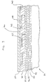
Figure 1 is a perspective view, partly in cross-section, showing a length of insulated flexible pipe. -
Figure 2 is a cross-sectional perspective view showing a thermal insulation layer not according to the invention. -
Figure 2a is a cross-sectional view showing the flexing of the thermal insulation layer ofFigure 2 during bending of the flexible pipe. -
Figure 3 is a cross-sectional perspective view showing another thermal insulation layer for an insulated flexible pipe. -
Figure 4 is a cross-sectional perspective view showing yet another thermal insulation layer for an insulated flexible pipe. -
Figure 5 is a cross-sectional perspective view showing yet another thermal insulation layer for an insulated flexible pipe. -
Figures 6 to 11 are cross-sectional views of thermal insulation tapes.Only embodiments offigures 9 and11 are according to the invention. - The invention relates to a styrenic thermal insulation product in the form of a tape or band which is adapted to be wound around a rigid or flexible pipe to form one or more thermal insulation layers in accordance with the invention, as well as insulated fluid and/or gas transport conduits incorporating such thermal insulation layers.
- The term "fluid and/or gas transport conduits", and similar terms as used herein, are intended to include such oil and gas pipelines and related components, including flowlines, risers, jumpers, spools, manifolds and ancillary equipment.
- The term "tape" or "band" as used herein refers to a flexible strip of material having a longitudinal dimension or length which is substantially greater than its transverse dimension or width, and which is generally flat with a thickness or height which is less than its transverse dimension. These embodiments of the invention are now described below with reference to the drawings. The thickness of the thermal insulation tapes described herein is variable, and may be in the range from about 5 to about 10 mm.
- The pre-formed thermal insulation tape may preferably be supplied in the form of a roll which can be unwound during application to the pipe. The tape may be wound around the pipe in a helical pattern, with individual windings of the tape either being spaced apart or overlapping each other at their edges so as to provide a continuous layer of insulating material. The tape of insulating material may have a rectangular cross section and may comprise one or more layers of thermal insulation and/or other optional layers. These layers may be separately formed and then adhered together, or they may be co-extruded. The thermal insulation layers may be solid (unfoamed) or foamed. For example, the tape may include an inner layer comprised of a foamed thermal insulation material and an outer, abrasion-resistant top coat which may be comprised of an unfoamed layer of polymer which is the same as or different from the polymer making up the foamed layer. In another embodiment, the tape of thermal insulating material may have a core layer which is foamed, with the core layer being surrounded by an outer surface layer of unfoamed polymer material.
- When applied to a rigid pipe, it may be preferred to adhere the individual windings of thermal insulation material to each other and/or to the pipe so as to form a continuous, bonded insulation layer. In this regard, it may be preferred to fuse the individual windings of insulating material to each other and to the pipe by application of heat. It may also be preferred to provide one surface of the band or tape of material with a layer of adhesive, for example by co-extrusion. The adhesive layer would be applied to the face of the insulating band or tape which comes into contact with the pipe surface, to adhere the tape or band to the pipe and also join together the overlapping edges of adjacent windings of insulating material.
- The tape of thermal insulating material may also be applied to fluid and/or gas transport conduits comprised of flexible pipes. Typically, the insulating tape will be applied to a flexible pipe as an unbonded insulation layer, i.e. wherein the individual windings are not adhered or bonded to either the surface of the pipe or to each other.
- Fluid and/or gas transport conduits comprised of flexible pipes may be used in petroleum production installations for the transport of fluids and gases through varying depths of water, as in risers which carry hot fluids such as hydrocarbons from depths in excess of 1,000 meters to the surface. Such flexible pipes may be of the "rough-bore" type, having an inner layer or "carcass" comprised of a helical winding of interlocking strips of metal. Alternatively, the flexible pipe may be of the "smooth-bore" type, having an inner polymeric liner. The insulating tapes according to the present invention are applicable to a wide variety of flexible pipe structures, including the rough bore and smooth bore varieties described above. Several embodiments of the invention will now be described below in connection with the application of a thermal insulation layer, in the form of a tape, to a typical flexible pipe structure.
-
Figure 1 illustrates a typicalflexible pipe structure 50 of the "rough bore" type having aninner carcass 52 comprised of a helically wound metal strip which forms an inner, permeable layer which is flexible and has high mechanical strength. Wrapped around thecarcass 52 is aninner liner 54 formed from an extruded layer of impermeable, heat resistant polymeric material which forms an impervious barrier between the exterior and interior of thepipe 50. Wrapped around theinner liner 54 are one or more layers offlexible pressure armour inner liner 54 at a relatively large angle to the longitudinal direction. Thepressure armour layers pipe 50. - Wrapped around the outside of the
pressure armour layers tensile armour layers pipe 50. The outermost layer ofpipe 50 comprises anouter sheath 64 which may preferably be comprised of an extruded layer of abrasion-resistant polymeric material. - As shown in
Figure 1 , between the layers oftensile armour outer sheath 64 there is provided at least onethermal insulation layer 66. Thethermal insulation layer 66 may comprise at least one length ofthermal insulation tape 68 which is helically wound around the entire length ofpipe 50 in one or more layers so as to provide thepipe 50 with a continuous layer of thermal insulation. The number of layers ofthermal insulation tape 68 making upthermal insulation layer 66 depends on a number of factors, including geometrical (pipe size) and thermal (required loss coefficient) considerations, as well as the thickness of theinsulation tape 68. Generally speaking, where the thickness of the insulation tape is from 5 - 10 mm, about 5 - 10 layers ofinsulation tape 68 may be applied to the pipe. The individual windings of thetape 68 may be spaced apart or may overlap one another, as further described below. It will be appreciated that thepipe 50 may be provided with two or more consecutively applied thermal insulation layers 66. - In the
pipe structure 50 described above, flexibility is provided by the wound or articulated structure of thecarcass 52 and the armour layers 56, 58, 60, 62. Likewise, it is preferred that thethermal insulation layer 66 also has an articulated structure so as not to impair flexibility of thepipe 50. This articulated structure may be provided by forming the thermal insulation tape with a cross-sectional shape which permits a limited amount of relative movement (also referred to herein as "slippage") in the longitudinal direction while maintaining overlap between adjacent windings of the tape. A wide variety of cross-sectional shapes are possible, including those specifically described below. - In some examples not part of the invention, the thermal insulation tape is provided with a cross-section which permits interlocking or overlapping of the windings and/or layers of tape, when the tape is applied as one or more layers. For example, the tape may include a flat, planar portion which is adapted to lie flat on the surface of the
pipe 50 or another layer of thermal insulation tape, and an interlocking or overlapping portion which is connected to the flat, planar portion and extends therefrom. The flat planar portions of the tape are preferably not adhered to one another or to thepipe 50, so as to permit slippage of the individual windings of the tape relative to the pipe, in a direction parallel to the longitudinal axis of the pipe. - The insulation tape may be provided with one or more interlocking or overlapping portions, depending on its cross-sectional shape. The interlocking or overlapping portions of adjacent windings of the tape are adapted to nest with one another and to permit a limited range of longitudinal slippage of the windings, while maintaining overlap between the edges of adjacent windings.
- In one examples not part of the invention illustrated in
Figures 2 ,2a and3 , thethermal insulation tape 68 comprises an interlocking U-shape or C-shape, having a flat,planar portion 70 with a firstmajor surface 72 and an opposed secondmajor surface 74, and having transversely spacededge portions major surface 72 is provided with a pair of locking portions in the form oflegs edge portions tape 68 and extend continuously along its length. Thelegs planar portion 70 oftape 68, although the angle may vary from about 45-90°. - In the example of
Figures 2 ,2a and3 , thethermal insulation layer 66 is made up of two individual lengths or layers of tape, labelled 68a and 68b.Length 68a forms an inner portion ofinsulation layer 66 and is wound aroundpipe 50 with itsfirst surface 72 andlegs pipe 50.Length 68b forms an outer portion ofinsulation layer 66 and is wound aroundpipe 50 with itsfirst surface 72 andlegs pipe 50. Thus, thelegs respective lengths tape 68 nest with one another such that eachleg length 68a is nested between twolegs length 68b, and vice versa. Eachleg tape 68 also engages thefirst surface 72 of an adjacent winding oftape 68. It will be appreciated that the appearance ofpipe 50 inFigure 2 is highly simplified, and that thepipe 50 is shown without theouter sheath 64 over theinsulation layer 66. Also, the relative thicknesses of the various layers ofpipe 50 inFigure 2 are not necessarily shown to scale. - As shown in
Figure 2a , theedge portions planar portions 70 overlap one another so that the twolayers pipe 50. Thelegs planar portions 70 during bending ofpipe 50. -
Figure 4 illustrates an interlockingthermal insulation tape 83 having a T-shaped cross section, including a flatplanar portion 84 with a firstmajor surface 86, a secondmajor surface 88 and transversely spacededge portions first surface 86 at an angle of about 90° is a locking portion in the form ofleg 94, theleg 94 being positioned approximately midway between theedge portions leg 94 extends at an angle of 90° from the flatplanar portion 84, but rather the angle may be in the range from 45-90°. - As with the example shown in
Figures 2 ,2a and3 , thethermal insulation layer 66 in this example is made up of two individual lengths or layers of the T-shapedtape 83, afirst length 83a which is wrapped aroundpipe 50 with itsfirst surface 86 andleg 94 facing away from thepipe 50 and asecond length 83b which has itsfirst surface 86 andleg 94 facing inwardly toward thepipe 50. As shown inFigure 4 , thelegs 94 oflengths planar portions 84, with eachleg 94 of each winding oflength 83a nested between thelegs 94 of two adjacent windings oflength 83b, and vice versa. Also, theleg 94 of each winding oftape 83 engages the edge portions of two adjacent windings oftape 83. - Yet another interlocking cross-sectional shape is illustrated in
Figure 5 , illustrating athermal insulation tape 95 having a Z-shaped or S-shaped cross section.Tape 95 includes a flatplanar portion 96 having a firstmajor surface 98 and a secondmajor surface 100 andedge portions Tape 95 is also provided with a pair oflegs tape 95. In particular,leg 106 extends from the firstmajor surface 98 andleg 108 extends from the secondmajor surface 100, withleg 106 being located inedge portion 102 andleg 108 extending in the opposite direction fromedge portion 104. It is not required that thelegs planar portion 96, but rather the angle may be in the range from 45-90°. - Since the
legs opposite surfaces planar portion 96, thethermal insulation layer 66 can be formed from a single length oftape 95. In order to permit interlocking of adjacent windings oftape 95, the firstmajor surface 98 may be provided with ashoulder 110 which reduces the thickness of the flatplanar portion 96 oftape 95 proximal to theleg 106 and the secondmajor surface 100 is similarly provided with ashoulder 112 which reduces the thickness of the flatplanar portion 96 oftape 95 proximal to theleg 108. Thus, a longitudinally-extendinggroove 114 is formed betweenshoulder 110 andleg 106 which houses theleg 108 of an adjacent winding oftape 95, and similarly a longitudinally-extendinggroove 116 is formed betweenshoulder 112 andleg 108 which houses theleg 106 of an adjacent winding oftape 95. Thegrooves tape 95 while maintaining overlap between theedge portions tape 95. - As mentioned above, the insulating tapes according to the invention may be of a single or multi-layer construction. In the examples described above with reference to
Figures 1 to 5 it is desired to permit slippage between adjacent windings of tape and therefore these insulating tapes are preferably not provided with adhesive layers on their outer surfaces. It may, however, be desirable to provide any of the insulation tapes described herein with layers of foamed and unfoamed polymeric materials so as to enhance their insulating and mechanical properties. For example, the insulation tapes described herein may be provided with an inner core layer comprised of a foamed polymeric material in order to provide the desired thermal insulating properties, with an outer unfoamed layer of polymeric material surrounding the core layer and providing the desired mechanical properties. It will be appreciated that the foamed and unfoamed layers may be formed from the same or different polymeric materials and may preferably be formed by co-extrusion. - With reference to the drawings,
Figures 3-5 illustrate examples of insulation tapes having a central core layer of foamed polymeric material and a surrounding surface layer of unfoamed polymeric material. In the T-shapedthermal insulation tape 83 shown inFigure 4 theleg 94 may be relatively thick so the foamedcore layer 118 extends throughout the flatplanar portion 84 and theleg 94, with asurface layer 120 of unfoamed polymeric material being provided over thecore layer 118. In the examples ofFigures 3 and5 the legs may be relatively thin and therefore, to ensure that the legs have sufficient mechanical strength, the foamed core layer may be present only in the flat planar portion of thetape Figure 3 , the flatplanar portion 70 oftape 68 is provided with acore layer 122 of foamed polymeric material whereas thesurface layer 124 of the flatplanar portion 70 and thelegs Figure 5 , the flatplanar portion 96 oftape 95 is provided with acore layer 126 of foamed polymeric material, while thesurface layer 128 of the flatplanar portion 96 and thelegs -
Figures 6 to 8 illustrate thermal insulation tape profiles in which the tape is provided with overlapping portions which do not interlock in the manner described above with reference toFigures 2 to 5 . The tapes according toFigures 6 to 8 are nevertheless constructed so as to maintain adequate overlap between the edges of adjacent windings during limited longitudinal slippage of the windings caused by bending of thepipe 50. As inFigure 2 , the appearance of the pipe inFigures 6 to 8 is greatly oversimplified by eliminating details of construction from all layers but theinsulation layer 66. Also, the relative thicknesses of the various layers ofpipe 50 inFigures 6 to 8 are not necessarily shown to scale. -
Figure 6 illustrates apipe 50 having athermal insulation layer 66 located between the tensile armour layers 60, 62 and theouter sheath 64. The thermal insulation layer is comprised of asingle layer 66 of athermal insulation tape 150 having a flatplanar portion 152 of approximately rectangular cross section, located between the having a firstmajor surface 154 and a secondmajor surface 156, with the firstmajor surface 154 facing inwardly toward the centre of thepipe 50 and the secondmajor surface 156 facing outwardly toward theouter sheath 64. Projecting from one edge of the flatplanar portion 152 is aleg 158 which overlaps the secondmajor surface 156 of flatplanar portion 152 of an adjacent winding oftape 150, theleg 158 having sufficient width so as to maintain overlap when the separation between adjacent windings increases during bending of the pipe. In order that the layer of insulation is of approximately constant thickness and to allow limited articulation of the insulation tape, theleg 158 and the secondmajor surface 156 of flatplanar portion 152 may have complementary shapes. In the example shown inFigure 6 , theleg 158 is wedge-shaped and decreases in thickness with increasing distance from the flatplanar portion 152, and the secondmajor surface 156 is sloped across at least a part of its width so as to engage the wedge-shapedleg 158. -
Figure 7 illustrates apipe 50 having athermal insulation layer 66 located between the tensile armour layers 60, 62 and theouter sheath 64. Thethermal insulation layer 66 is comprised of a single layer of athermal insulation tape 160 which is similar totape 150 ofFigure 6 , having a flatplanar portion 162 of approximately rectangular cross section, having a firstmajor surface 164 and a secondmajor surface 166, with the firstmajor surface 164 facing inwardly toward the centre of thepipe 50 and the secondmajor surface 166 facing outwardly toward theouter sheath 64. Projecting from one edge of the flatplanar portion 162 is aleg 168 which overlaps the secondmajor surface 166 of flatplanar portion 162 of an adjacent winding oftape 160, theleg 168 having sufficient width so as to maintain overlap when the separation between adjacent windings increases during bending of the pipe. As in the example ofFigure 6 , theleg 168 and the secondmajor surface 166 of flatplanar portion 162 have complementary shapes, with theleg 168 having a rectangular cross-section and the secondmajor surface 166 being notched or rebated to receive theleg 168. -
Figure 8 illustrates yet another example of apipe 50 having athermal insulation layer 66 located between the tensile armour layers 60, 62 and theouter sheath 64. Thethermal insulation layer 66 is comprised of an overlappingthermal insulation tape 170, which is a variant of thetape 150 shown inFigure 6 .Tape 170 has a flatplanar portion 172 of approximately rectangular cross section, having a firstmajor surface 174 and a secondmajor surface 176, with the firstmajor surface 174 facing inwardly toward the centre of thepipe 50 and the secondmajor surface 176 facing outwardly toward theouter sheath 64. Projecting from one edge of the flatplanar portion 172 is aleg 178 which overlaps the secondmajor surface 176 of flatplanar portion 172 of an adjacent winding oftape 170, theleg 178 having sufficient width so as to maintain overlap when the separation between adjacent windings increases during bending of the pipe. As in the example ofFigure 6 , theleg 178 and the secondmajor surface 176 of flatplanar portion 172 have complementary shapes, with theleg 178 having a triangular cross-section and the secondmajor surface 176 being chamfered along one edge to engage thetriangular leg 178. - Although the overlapping insulation tapes illustrated in
Figures 6 to 8 are adapted to maintain a continuous layer of insulation when applied as a single layer, it will be appreciated that a flexible pipe can be provided with two or more layers of any of these tapes, depending at least partly on the desired thickness ofinsulation layer 66 and on the thickness of thethermal insulation tape - It is not necessary that the insulating tapes overlap or interlock. In this regard, the insulating tapes described below and illustrated in
Figures 9 and11 are non-interlocking, nonoverlapping tapes of generally rectangular cross-section. In order to provideflexible pipe 50 with a continuous insulatinglayer 66 of sufficient thickness, the tapes ofFigures 9 to 11 may be applied in two or more layers, with the gaps of adjacent layers being staggered. As mentioned above, the number of layers depends at least partly on the desired thickness ofinsulation layer 66 and on the thickness of the thermal insulation tapes described below. -
Figure 9 illustrates apipe 50 having athermal insulation layer 66, according to the invention, located between the tensile armour layers 60, 62 and theouter sheath 64. The thermal insulation layer is comprised of aninsulating tape 180 with a simple rectangular cross-section, comprising a flat planar portion with a firstmajor surface 182, a secondmajor surface 184 and a pair of vertical side surfaces 186, 188, the firstmajor surface 182 facing inwardly toward the centre of thepipe 50 and the secondmajor surface 184 facing outwardly towardsheath 64. Thetape 180 is applied to thepipe 50 with a gap (for example about 3 mm) being provided between the side surfaces 186, 188 of adjacent windings in each layer. As mentioned above, thepipe 50 may be provided with two or more layers oftape 180 so as to provide thepipe 50 with acontinuous insulation layer 66, with the gaps in adjacent layers being staggered, for example by about 50 percent. -
Figures 10 and11 illustrate variants of the rectangularinsulating tape 180 ofFigure 9 . The portions ofpipe 50 shown inFigures 10 and11 are restricted to enlarged areas A' and A", which are identical to area A ofFigure 9 except for the variations in the insulation tapes described below. In other words, the insulation tapes ofFigures 10 and11 are intended to be applied topipe 50 in the same manner astape 180 ofFigure 9 . -
Figure 10 illustratesinsulation tape 190 having first and secondmajor surfaces side surfaces tape 180 ofFigure 10 except that side surfaces 196, 198 are continuously curved between themajor surfaces tape 200 ofFigure 11 is similar, having first and secondmajor surfaces side surfaces tape 190 ofFigure 10 except that only the transitions betweenmajor surfaces side surfaces major surfaces tape 180, a flexible pipe may be provided with two or more layers oftape - A variant of
Figures 10 and11 could be provided in which the transitions between the major surfaces and the side surfaces are smoothly rounded as inFigure 11 , and wherein the side surfaces are smoothly rounded as inFigure 10 . - Although
pipe 50 is not shown in detail inFigures 2 to 11 , it will be appreciated that the thermal insulation tapes illustrated inFigures 2 to 11 may be applied to a "rough bore"pipe 50 having the same construction shown inFigure 1 , or may be applied to flexible pipes having alternate structures, including the "smooth bore" pipes described above. - The thermal insulation tapes according to the present invention may exhibit all the following properties at the average operating temperature of the pipe:
- high compressive triaxial creep resistance of 0-10% compression after 20 years at 60 degrees C under a load of about 5-15 MPa,
- high uniaxial compressive strength (>25 MPa),
- low thermal conductivity (≤0.170 W/mK),
- high specific heat capacity (>1000 J/kgK),
- long term temperature withstand capability (up to 100°C),
- adequate ductility (>10% elongation at break)
- The thermal insulation layers according to the present invention are prepared from polystyrene or styrene-based thermoplastics, including polystyrene homopolymer, polystyrene copolymer, high-impact polystyrene, and modified polystyrene. The modified polystyrene comprises polystyrene which is blended, grafted or copolymerized with butadiene, polybutadiene, polyethylene, polypropylene, polybutene-1, polyphenylene oxide, styrene-butadiene, styrene-butadiene-styrene, styrene-isoprene-styrene, styrene-ethylene/butylene-styrene, ethylene-propylene, acrylonitrile, butadiene-acrylonitrile, α-methyl styrene, acrylic ester, methyl methacrylate, polycarbonate, or polyphenylene ether.
- Thermal insulation compositions prepared from these materials may also contain additives selected from one or more members of the group comprising inorganic fillers, reinforcing fillers, nano-fillers, conductive fillers, flame-retardant fillers, antioxidants, heat-stabilisers, process aids, compatibilisers, and colourants.
- Foamed thermal insulation layers in the insulating and protective coatings according to the invention can be prepared from the aforementioned polystyrene or styrene-based thermoplastics, by incorporating chemical foaming agents, by the physical injection of gas or volatile liquid, or by blending with hollow polymer, glass or ceramic microspheres.
- The chemical foaming agents may function through either an endothermic (heat absorbing) or exothermic (heat generating) reaction mechanism, and are selected from one or more members of the group comprising sodium bicarbonate, citric acid, tartaric acid, azodicarbonamide, 4,4-oxybis (benzene sulphonyl) hydrazide, 5-phenyl tetrazole, dinitrosopentamethylene tetramine, p-toluene sulphonyl semicarbazide, or blends thereof. Preferably the chemical foaming agent is an endothermic foaming agent, such as sodium bicarbonate blended with citric or tartaric acid.
- Chemical foaming occurs when the foaming agent generates a gas, usually CO2 or N2, through decomposition when heated to a specific temperature. The initial decomposition temperature along with gas volume, release rate and solubility are important parameters when choosing a chemical foaming agent and they need to be carefully matched to the processing temperature of the particular thermoplastic being foamed.
- The gas or volatile liquid used for physical injection is selected from the group comprising CO2, supercritical CO2, N2, air, helium, argon, aliphatic hydrocarbons, such as butanes, pentanes, hexanes and heptanes, chlorinated hydrocarbons, such as dichloromethane and trichloroethylene, and hydrochlorofluorocarbons, such as dichlorotrifluoroethane. In the case of a volatile liquid, foaming occurs when the heated liquid vaporizes into gas. Preferably the physical foaming agent is supercritical CO2.
- The hollow microspheres are selected from one or more members of the group comprising glass, polymeric, or ceramic, including silica and alumina, microspheres. Preferably the hollow microspheres are lime-borosilicate glass microspheres. Foamed thermal insulation layers incorporating hollow microspheres are also referred to herein as "syntactic" foams.
- Extrusion may be accomplished using single screw extrusion, either in single or tandem configuration, or by twin-screw extrusion methods. When extruding foamed insulation it is important that foaming be prevented until the polymer exits the extrusion die.
- The insulation may be extruded as a single strip or as a sheet that is subsequently slit into individual strips.
- In the case of single screw extrusion, the extruder screw may be either a single stage or a 2-stage design. A single stage would be adequate for chemical foam extrusion whereby the foaming agent is added as a pelleted concentrate or masterbatch which is pre-mixed with the polymer to be foamed using a multi-component blender, for example, mounted over the main feed port of the extruder. In the 2-stage screw design, the first and second stages are separated by a decompression zone, at which point a gas or liquid physical foaming agent can be introduced into the polymer melt via an injection or feed port in the extruder barrel. The first stage acts to melt and homogenize the polymer, whereas the second stage acts to disperse the foaming agent, cool the melt temperature, and increase the melt pressure prior to the melt exiting the die. This may also be accomplished by tandem extrusion, wherein the two stages are effectively individual single screw extruders, the first feeding into the second. The design of the screw is important and it may incorporate barrier flights and mixing elements to ensure effective melting, mixing, and conveying of the polymer and foaming agent.
- With respect to the particular foam insulations described herein, it is important that conditions of mixing, temperature and pressure are adjusted to provide a uniform foam structure comprising small or microcellular bubbles with a narrow size distribution evenly distributed within the polymer matrix in order to ensure maximum compressive strength and compressive creep resistance of the insulation when subjected to high external pressures.
- Twin screw extrusion is preferred where the polymer to be foamed is shear sensitive or if it is required that fillers or other additives be incorporated into the foam composition. It is recommended for preparation of syntactic foams or foams prepared by physical injection of a gas or liquid foaming agent. Since the twin screw design is usually modular, comprising several separate and interchangeable screw elements, such as mixing and conveying elements, it offers great versatility in tailoring the screw profile for optimum mixing and melt processing. In the case of syntactic foams, for example, the hollow microspheres are fed directly into the polymer melt using a secondary twin-screw feeder downstream of the main feed hopper. Additionally, a static mixing attachment or gear pump may be inserted between the end of the screw and the die to further homogenize the melt, generate melt pressure, and minimize melt flow fluctuations.
- For a foamed thermal insulation, the degree of foaming is dependant upon the required balance of thermal conductivity and compressive strength. Too high a degree of foaming may be detrimental to the compressive strength and creep resistance of the foam. The thermoplastic foams of the present invention are typically foamed from about 5% to about 50%, more preferably 10% to 30%. The degree of foaming is defined herein as the degree of rarefaction, i.e. the decrease in density, and is defined as [(Dmatrix - Dfoam)/Dmatrix]
X 100. Expressed in this way, the degree of foaming reflects the volume percentage of gas under the assumption that the molecular weight of gas is negligible compared to that of the matrix, which is generally true. In the alternative, the degree of foaming can be measured visually by microscopic determination of cell density. - The present invention is illustrated by way of the following examples and with reference to the
drawings 9 and 11. - An insulating tape with a rectangular cross-section of
width 50 +/-2.5 mm and thickness 5 +/- 0.4 mm was extruded from unfoamed high impact polystyrene (Melt Flow Rate, 3.5 g/10 min and Density, 1030 kg/m3) at a melt temperature of 200 degrees C. The tape thus produced was tested for the properties in Table 1. - An insulating tape with a rectangular cross-section of
width 50 +/-2.5 mm and thickness 10 +/- 0.4 mm was extruded from the high impact polystyrene of Example 1 foamed to a density of 850 kg/m3 using 0.8% of an endothermic foaming agent. The tape thus produced was tested for the properties in Table 1. - An insulating tape with a rectangular cross-section of
width 50 +/-2.5 mm and thickness 10 +/- 0.4 mm was extruded from the unfoamed high impact polystyrene of Example 1 modified with 20% styrene-butadiene-styrene block copolymer (Melt Flow Rate, 13 g/10 min and Density, 1000 kg/m3). The tape thus produced was tested for the properties in Table 1. - One or more layers of the insulation tapes produced in Examples 1 to 3 were helically wound around the internal armoured cores of flexible pipes as described earlier to provide an insulation layer as per product design requirements.
Table 1 - Insulation Properties PROPERTY TEST METHOD EXAMPLE 1 EXAMPLE 2 EXAMPLE 3 Density, kg/m3 ASTM D792 1030 850 1020 Degree of Foaming, % Calculated as above 0 17.5 0 Thermal conduc tivity, W/mK (single layer) ASTM C177 0.155 +/-5% 0.130 +/-5% 0.170 +/-5% Specific Heat Capacity, J/kgK ASTM E1269 1150 +/-5% 1150 +/-5% 1150 +/-5% Vicat Softening Point B/50, °C ASTM D1525 105 +/- 5 105 +/- 5 80 +/-5 Tensile Strength at Yield, MPa ASTM D638 14 +/- 0.5 9 +/- 0.3 13 +/- 0.5 Elongation at Yield, % ASTM D638 2 +/- 0.5 4 +/- 0.5 5 +/- 0.5 Elongation at Break, % ASTM D638 30 +/- 5 20 +/- 2 75 +/- 10 Flexural Modulus, MPa ASTM D638 2300 +/-200 900 +/-100 800 +/-100 Triaxial Compressive Creep, % after 20 years at 60°C and 5 MPa InSpec 1-1-4-140/SP01 <1.0 <1.5 <1.0 Water Absorption Saturated, 23°C, % ASTM D570 <0.1 <0.1 <0.1 - Although the wrappable styrenic pipe insulations disclosed herein may be applied between the armour layers and the outer sheath of a flexible fluid and/or gas transport conduit, it will be appreciated that the wrappable styrenic pipe insulations disclosed herein may instead or additionally be applied at other locations within the layered structure of a flexible fluid and/or gas transport conduit. For example, the wrappable styrenic pipe insulations disclosed herein may be applied between the
inner liner 54 and the layers offlexible pressure armour flexible pipe structure 50 described above. - Although the invention has been described in connection with certain embodiments thereof, it is not limited thereto. Rather, the invention includes all embodiments which may fall within the scope of the following claims.
Claims (10)
- A wrappable, styrenic thermal insulation product for application to a flexible, armoured pipe, comprising:an elongate tape comprising a flat, planar portion of generally rectangular cross-section and having a first major surface, an opposed second major surface, a pair of opposed side surfaces extending between the first and second major surfaces, a width and a thickness, wherein the width of the flat, planar portion is greater than the thickness;wherein the tape comprises polystyrene or a styrene-based thermoplastic, characterised in that the tape has the following properties:
uniaxial compressive strength >25 MPa; andthermal conductivity ≤0.170 W/mK. - The wrappable, styrenic thermal insulation product of claim 1, wherein the flat planar portion is provided with rounded edges at corners between the side surfaces and the first and second major surfaces, and wherein the side surfaces include straight portions extending between said rounded edges.
- The wrappable, styrenic thermal insulation product of any one of claims 1 to 2, wherein the polystyrene or styrene-based thermoplastic is selected from one or more members of the group consisting of: polystyrene homopolymer, polystyrene copolymer, high-impact polystyrene and modified polystyrene.
- The wrappable, styrenic thermal insulation product of claim 3, wherein the modified polystyrene comprises polystyrene which is blended, grafted or copolymerized with butadiene, polybutadiene, polyethylene, polypropylene, polybutene-1, polyphenylene oxide, styrene-butadiene, styrene-butadiene-styrene, styrene-isoprene-styrene, styrene-ethylene/butylene-styrene, ethylene-propylene, acrylonitrile, butadiene-acrylonitrile, α-methyl styrene, acrylic ester, methyl methacrylate, polycarbonate, or polyphenylene ether.
- The wrappable, styrenic thermal insulation product of any one of claims 1 to 4, wherein the polystyrene or styrene-based thermoplastic is unfoamed.
- The wrappable, styrenic thermal insulation product of any one of claims 1 to 4, wherein the polystyrene or styrene-based thermoplastic is foamed and contains gas bubbles and/or hollow micro-spheres, and wherein a degree of foaming is about 5-50 percent.
- The wrappable, styrenic thermal insulation product of any one of claims 1 to 4, wherein the elongate tape has a core layer which is foamed and a surface layer surrounding the core layer, wherein the surface layer is unfoamed.
- The wrappable, styrenic thermal insulation product of any one of claims 1 to 7, having a density in the range from about 700 - 1050 kg/m3, preferably in the range from about 850 - 1030 kg/m3.
- A flexible, armoured pipe comprising a flexible, cylindrical metal carcass surrounded by at least one layer of flexible metal armour;
wherein the pipe further comprises a layer of thermal insulation surrounding the armour;
wherein the layer of thermal insulation is comprised of one or more layers of the wrappable, styrenic thermal insulation product of any one of claims 1 to 8, and wherein each layer of the tape is comprised of a plurality of windings arranged adjacent to one another;
wherein the thermal insulation tape is comprised of a thermoplastic material, and comprises a flat, planar portion which is substantially parallel to an axis defined by the carcass and the armour. - The flexible, armoured pipe of claim 9, wherein the pipe further comprises an external, polymeric sheath provided over the armour, and wherein the at least one layer of thermal insulation is located between the armour and the external, polymeric sheath.
Applications Claiming Priority (2)
| Application Number | Priority Date | Filing Date | Title |
|---|---|---|---|
| US13965008P | 2008-12-22 | 2008-12-22 | |
| PCT/CA2009/001891 WO2010072001A1 (en) | 2008-12-22 | 2009-12-22 | Wrappable styrenic pipe insulations |
Publications (3)
| Publication Number | Publication Date |
|---|---|
| EP2379933A1 EP2379933A1 (en) | 2011-10-26 |
| EP2379933A4 EP2379933A4 (en) | 2013-05-15 |
| EP2379933B1 true EP2379933B1 (en) | 2018-05-16 |
Family
ID=42264326
Family Applications (1)
| Application Number | Title | Priority Date | Filing Date |
|---|---|---|---|
| EP09833986.4A Active EP2379933B1 (en) | 2008-12-22 | 2009-12-22 | Wrappable styrenic pipe insulations |
Country Status (5)
| Country | Link |
|---|---|
| US (1) | US8485229B2 (en) |
| EP (1) | EP2379933B1 (en) |
| BR (1) | BRPI0924891B1 (en) |
| MY (1) | MY157589A (en) |
| WO (1) | WO2010072001A1 (en) |
Cited By (1)
| Publication number | Priority date | Publication date | Assignee | Title |
|---|---|---|---|---|
| FR3161008A1 (en) * | 2024-04-09 | 2025-10-10 | Technipfmc Subsea France | Flexible subsea pipe comprising an intermediate polymeric layer based on poly(p-phenylene ether) |
Families Citing this family (35)
| Publication number | Priority date | Publication date | Assignee | Title |
|---|---|---|---|---|
| EP2304299B1 (en) | 2008-06-09 | 2017-10-04 | Flexsteel Pipeline Technologies, Inc. | Flexible pipe joint |
| CN102356264B (en) * | 2009-03-18 | 2013-07-17 | 迪普弗莱克斯有限公司 | Composite flexible pipe and method of manufacture |
| WO2013052639A2 (en) | 2011-10-04 | 2013-04-11 | Flexsteel Pipeline Technologies, Inc. | Pipe end fitting with improved venting |
| US9976687B2 (en) | 2012-05-18 | 2018-05-22 | Saprex, Llc | Breathable multi-component exhaust insulation system |
| WO2014008148A1 (en) | 2012-07-03 | 2014-01-09 | 3M Innovative Properties Company | Siloxane-based pipe coatings |
| CN103672221A (en) * | 2012-09-08 | 2014-03-26 | 天津市海王星海上工程技术有限公司 | Composite soft tube suitable for ocean heat preservation mixed transportation |
| US9388515B2 (en) | 2012-09-28 | 2016-07-12 | Saprex, Llc | Heat curable composite textile |
| WO2014086858A2 (en) * | 2012-12-04 | 2014-06-12 | Carlsberg Breweries A/S | A beverage dispensing assembly comprising beverage distribution python and a method of producing the beverage distribution python |
| US9067397B2 (en) * | 2013-03-11 | 2015-06-30 | Changchun Gaoxiang Special Pipe Co., Ltd. | Hybrid pipe design and method of manufacture |
| EP3201509B1 (en) | 2014-09-30 | 2020-01-01 | Flexsteel Pipeline Technologies, Inc. | Connector for pipes |
| BR112018008814B1 (en) | 2015-11-02 | 2022-07-12 | Flexsteel Pipeline Technologies, Inc | REAL-TIME INTEGRITY MONITORING METHOD OF TERRESTRIAL TUBES |
| EP3443254B1 (en) | 2016-04-15 | 2023-12-13 | Saprex, LLC | Composite insulation system |
| US10981765B2 (en) | 2016-06-28 | 2021-04-20 | Trinity Bay Equipment Holdings, LLC | Half-moon lifting device |
| US11208257B2 (en) | 2016-06-29 | 2021-12-28 | Trinity Bay Equipment Holdings, LLC | Pipe coil skid with side rails and method of use |
| US10745533B2 (en) * | 2016-07-15 | 2020-08-18 | Sabic Global Technologies B.V. | Foamed thermoplastic material, method for the manufacture thereof, articles prepared therefrom, and article-forming method |
| MX2019004060A (en) | 2016-10-10 | 2019-09-19 | Trinity Bay Equipment Holdings Llc | Installation trailer for coiled flexible pipe and method of utilizing same. |
| CA3040103A1 (en) | 2016-10-10 | 2018-04-19 | Trinity Bay Equipment Holdings, LLC | Expandable drum assembly for deploying coiled pipe and method of using same |
| JP6940608B2 (en) | 2016-11-18 | 2021-09-29 | サプレックス,リミテッド・ライアビリティ・カンパニー | Composite insulation system |
| US10526164B2 (en) | 2017-08-21 | 2020-01-07 | Trinity Bay Equipment Holdings, LLC | System and method for a flexible pipe containment sled |
| WO2019089747A1 (en) | 2017-11-01 | 2019-05-09 | Trinity Bay Equipment Holdings, LLC | System and method for handling reel of pipe |
| AU2019215108B2 (en) | 2018-02-01 | 2024-06-13 | Flexsteel Usa, Llc | Pipe coil skid with side rails and method of use |
| WO2019165218A1 (en) | 2018-02-22 | 2019-08-29 | Trinity Bay Equipment Holdings, LLC | System and method for deploying coils of spoolable pipe |
| AU2019359460B2 (en) | 2018-10-12 | 2024-12-12 | Flexsteel Usa, Llc | Installation trailer for coiled flexible pipe and method of utilizing same |
| AR118122A1 (en) | 2019-02-15 | 2021-09-22 | Trinity Bay Equipment Holdings Llc | FLEXIBLE TUBE HANDLING SYSTEM AND METHOD TO USE THE SAME |
| US10753512B1 (en) | 2019-03-28 | 2020-08-25 | Trinity Bay Equipment Holdings, LLC | System and method for securing fittings to flexible pipe |
| US10926972B1 (en) | 2019-11-01 | 2021-02-23 | Trinity Bay Equipment Holdings, LLC | Mobile cradle frame for pipe reel |
| CN114981581A (en) | 2019-11-22 | 2022-08-30 | 圣三一海湾设备控股有限公司 | Canned Tube Fitting System and Method |
| WO2021102318A1 (en) | 2019-11-22 | 2021-05-27 | Trinity Bay Equipment Holdings, LLC | Reusable pipe fitting systems and methods |
| DK4058709T3 (en) | 2019-11-22 | 2025-06-16 | Flexsteel Usa Llc | SYSTEMS AND PROCESSES FOR WELDED PIPE FITTINGS |
| US10822194B1 (en) | 2019-12-19 | 2020-11-03 | Trinity Bay Equipment Holdings, LLC | Expandable coil deployment system for drum assembly and method of using same |
| US10844976B1 (en) | 2020-02-17 | 2020-11-24 | Trinity Bay Equipment Holdings, LLC | Methods and apparatus for pulling flexible pipe |
| GB2596283A (en) * | 2020-06-15 | 2021-12-29 | Stephen Boyce Gerard | Thermoplastic composite pipe |
| CN112963633B (en) * | 2021-02-24 | 2021-12-07 | 中国石油大学(北京) | Pressure-resistant armor layer for marine composite hose and special profiled bar thereof |
| CN115234722B (en) * | 2022-07-13 | 2024-10-11 | 中国石油大学(北京) | Pi-like section special-shaped material for composite hose and skeleton layer |
| GB202211143D0 (en) * | 2022-07-29 | 2022-09-14 | Baker Hughes Energy Technology UK Ltd | Permeation-barrier and method of manufacture |
Family Cites Families (112)
| Publication number | Priority date | Publication date | Assignee | Title |
|---|---|---|---|---|
| US2797731A (en) * | 1955-10-06 | 1957-07-02 | Monsanto Chemicals | Method for preventing moisture condensation on cold pipes |
| DE1281676B (en) * | 1964-12-30 | 1968-10-31 | Manfred Hawerkamp | Process for the production of pipes and containers from helically wound strip material made of thermoplastic plastics |
| US3731710A (en) * | 1965-08-27 | 1973-05-08 | Exxon | Spray foam insulated pipe |
| US3614967A (en) * | 1968-10-08 | 1971-10-26 | Royston Lab | Multilayered pipe coatings and coated pipe |
| CA922224A (en) * | 1969-05-17 | 1973-03-06 | Jarvis Harold | Method of applying protective coatings to pipes |
| US3654061A (en) * | 1970-11-19 | 1972-04-04 | Hood Sponge Rubber Co | Pipe wrap |
| SE362463B (en) | 1971-08-27 | 1973-12-10 | Graenges Hedlund Ab | |
| US3755029A (en) * | 1971-11-17 | 1973-08-28 | Amchem Prod | Protective coated thermal insulation |
| DE2331643C3 (en) * | 1972-06-24 | 1975-10-09 | Mitsubishi Petrochemical Co., Ltd., Tokio | Hose, especially heat protection hose |
| US3954539A (en) * | 1972-11-01 | 1976-05-04 | The Dow Chemical Company | Cryogenic construction and article therefor |
| US3929166A (en) * | 1973-08-09 | 1975-12-30 | Gen Electric | Pipeline thermal insulation |
| DE2416812C2 (en) | 1974-04-06 | 1983-04-07 | Bayer Ag, 5090 Leverkusen | Process for the production of free-flowing hollow beads from vinyl chloride-ethylene copolymers |
| US4013987A (en) * | 1975-08-22 | 1977-03-22 | Westinghouse Electric Corporation | Mica tape binder |
| US4038339A (en) * | 1975-09-16 | 1977-07-26 | Westinghouse Electric Corporation | Epoxy-vinyl-polyester cold blended resin composition |
| GB1579125A (en) * | 1976-06-14 | 1980-11-12 | Sigmund F | Heat-insulated pipe-lines |
| SE439678B (en) | 1976-10-04 | 1985-06-24 | Pont A Mousson | PRE-INSULATED PIPE FOR MARKING |
| DE2700478C2 (en) | 1977-01-07 | 1986-07-10 | Kabel- und Metallwerke Gutehoffnungshütte AG, 3000 Hannover | Process for the production of a heat and sound insulated pipe |
| US4151366A (en) * | 1977-06-30 | 1979-04-24 | General Electric Company | Flame resistant, insulated multi-conductor electric cable |
| US4176106A (en) | 1977-07-28 | 1979-11-27 | Union Carbide Corporation | Phenol/formaldehyde resoles and cellular products derived therefrom |
| FR2417707A1 (en) * | 1978-02-21 | 1979-09-14 | Coflexip | FLOATING FLEXIBLE TUBES |
| JPS5624289A (en) * | 1979-07-31 | 1981-03-07 | Furukawa Electric Co Ltd | Adiabatic pipe and its manufacture |
| DE8002596U1 (en) * | 1980-02-01 | 1980-05-14 | Dynamit Nobel Ag, 5210 Troisdorf | MACHINE FOR THE PRODUCTION OF THICK-WALLED INSULATING TUBES FROM FOAM PLASTICS |
| JPS5835607B2 (en) * | 1980-03-21 | 1983-08-03 | 保土谷化学工業株式会社 | Method for producing polyurethane modified polyisocyanurate foam |
| FR2479945A1 (en) * | 1980-04-03 | 1981-10-09 | Brangues Chaudronnerie Tuyaute | PROCESS FOR THE CALORIFUGEAGE OF CONDUITS AND DUCTS OBTAINED |
| SE434815B (en) * | 1982-02-23 | 1984-08-20 | Lindab Nord Ab | SET FOR MANUFACTURE OF ISOLATED PIPE CONTROL PARTS |
| US4589275A (en) * | 1982-04-16 | 1986-05-20 | The Kendall Company | Pipe coating |
| US4523141A (en) * | 1982-04-16 | 1985-06-11 | The Kendall Company | Pipe coating |
| US4713271A (en) * | 1982-06-30 | 1987-12-15 | Cosden Technology, Inc. | Foamed polymer tubing |
| DE3370680D1 (en) * | 1982-12-23 | 1987-05-07 | Webco Ind Rubber Ltd | Insulated pipeline |
| CA1216505A (en) | 1983-08-26 | 1987-01-13 | James J. Stockman | Method and apparatus for applying a coating material to a pipe |
| CA1200216A (en) * | 1983-12-22 | 1986-02-04 | Farrokh A. Patell | Prefabricated thermally insulated pipeline section and method for its fabrication |
| DE3409734A1 (en) * | 1984-03-20 | 1985-09-26 | The Furukawa Electric Co., Ltd., Tokio/Tokyo | BENDING PIPELINE FOR THE TRANSPORT OF FLOWING MEDIA |
| US4590108A (en) * | 1984-07-11 | 1986-05-20 | Nippe Reynold B | Method and system for insulating pipes |
| US4657050A (en) * | 1984-07-25 | 1987-04-14 | Shell Oil Company | Pipeline insulation system |
| US4603182A (en) * | 1984-10-05 | 1986-07-29 | General Electric Company | Low viscosity epoxy resin compositions |
| US4676695A (en) * | 1985-11-01 | 1987-06-30 | Union Oil Company Of California | Method for preventing thaw settlement along offshore artic pipelines |
| US4778703A (en) * | 1987-04-02 | 1988-10-18 | Compac Corporation | Adhesive tape for insulation application |
| NO163648C (en) * | 1987-04-29 | 1990-06-27 | Dag Vilnes | PROCEDURE FOR INSULATING A RUBBER SUBMITTED IN WATER. |
| GB2215427B (en) | 1988-03-04 | 1992-07-29 | Marathon Oil U K Ltd | Coated pipes |
| US5026451A (en) * | 1988-05-12 | 1991-06-25 | Shaw Industries Ltd. | Method and apparatus for applying thermo-plastic protective coating to pipes |
| FI82635C (en) | 1988-08-23 | 1991-04-10 | Muotekno Ab Oy | Method and apparatus for joining tubular plastic products |
| GB8918218D0 (en) * | 1989-08-09 | 1989-09-20 | Boc Group Plc | Thermal insulation |
| GB9114585D0 (en) | 1991-07-05 | 1991-08-21 | Shell Int Research | Insulated flowline bundle |
| BR9206878A (en) | 1991-12-07 | 1995-11-28 | Thomas Christopher Arnott | Processes of applying a thermal insulation / anti-corrosion coating to a tube and a friction material added to a surface of an elastomeric material and tube thermally insulated and protected against corrosion |
| US5597522A (en) * | 1992-06-19 | 1997-01-28 | Shell Research Limited | Method of making polyolefin/filler composite materials |
| AU659314B2 (en) | 1992-06-19 | 1995-05-11 | Shell Internationale Research Maatschappij B.V. | Polyolefin/filler composite materials and their use |
| IT1264781B1 (en) | 1993-04-06 | 1996-10-10 | Himont Inc | PROCEDURE FOR COATING METALLIC PIPES WITH POLYOLEFIN MATERIALS |
| GB9311715D0 (en) | 1993-06-07 | 1993-07-21 | Liquid Polymers Group Plc | Improvements in or relating to pipe coating |
| DE4421817A1 (en) | 1994-06-22 | 1996-01-04 | Bayer Ag | Insulating of tubes, esp. for long-distance heat supply |
| US6155305A (en) * | 1994-08-29 | 2000-12-05 | Sumner; Glen R. | Offshore pipeline with waterproof thermal insulation |
| US5869591A (en) * | 1994-09-02 | 1999-02-09 | The Dow Chemical Company | Thermoset interpolymers and foams |
| FR2729211A1 (en) | 1995-01-06 | 1996-07-12 | Villain Sa | PIPE INSULATION ASSEMBLY FORM OF ELEMENTS AND METHOD OF MANUFACTURING SUCH ELEMENTS |
| FR2732441B1 (en) * | 1995-03-29 | 1997-05-30 | Coflexip | FLEXIBLE TUBULAR PIPE WITH POLYMERIC INTERNAL SEALING SHEATH |
| US6142707A (en) * | 1996-03-26 | 2000-11-07 | Shell Oil Company | Direct electric pipeline heating |
| US6264401B1 (en) * | 1995-12-29 | 2001-07-24 | Shell Oil Company | Method for enhancing the flow of heavy crudes through subsea pipelines |
| FR2743614B1 (en) * | 1996-01-11 | 1998-02-13 | Coflexip | FLEXIBLE PIPING |
| GB9609296D0 (en) | 1996-05-03 | 1996-07-10 | Balmoral Group | Insulating coating |
| GB9613973D0 (en) * | 1996-07-03 | 1996-09-04 | Bredero Price Services | Improvements in or relating to field joints |
| CA2234313A1 (en) * | 1997-04-07 | 1998-10-07 | Joseph A. Charlson | Composite insulated framing members and envelope extension system for buildings |
| US6058979A (en) * | 1997-07-23 | 2000-05-09 | Cuming Corporation | Subsea pipeline insulation |
| JPH1190972A (en) * | 1997-09-18 | 1999-04-06 | Uc Sangyo Kk | Manufacture of heat insulation hose |
| US6065781A (en) * | 1998-05-29 | 2000-05-23 | Power Lone Star, Inc. | Method and apparatus for protecting the weld area of polyolefin coated pipe |
| US6199595B1 (en) * | 1998-06-04 | 2001-03-13 | Jerry G. Baker | Insulated marine pipe apparatus and method of installation |
| FR2779801B1 (en) * | 1998-06-11 | 2000-07-21 | Inst Francais Du Petrole | PROCESS FOR THERMAL INSULATION OF PRODUCTION TUBINGS PLACED IN A WELL BY MEANS OF NON-RIGID FOAM |
| US6382259B1 (en) * | 1998-06-22 | 2002-05-07 | Corus Uk Limited | Insulated pipework systems |
| JP3322852B2 (en) * | 1998-06-26 | 2002-09-09 | 日清紡績株式会社 | Open cell rigid polyurethane foam molding and method for producing the same |
| US5996643A (en) * | 1998-09-18 | 1999-12-07 | Stonitsch; Lawrence J. | Foam insulation system for pipes |
| GB9905037D0 (en) * | 1999-03-05 | 1999-04-28 | Raychem Sa Nv | Method of sealing a joint between two pipes |
| AU4536900A (en) | 1999-05-26 | 2000-12-18 | Thermotite As | Steel tube with heat insulation for subsea pipelines and method of producing same |
| US6145546A (en) * | 1999-06-03 | 2000-11-14 | Coflexip | Flexible flowline for conveying fluids |
| US6397895B1 (en) | 1999-07-02 | 2002-06-04 | F. Glenn Lively | Insulated pipe |
| US6527015B2 (en) * | 1999-07-02 | 2003-03-04 | F. Glenn Lively | Insulated pipe |
| GB9917733D0 (en) * | 1999-07-28 | 1999-09-29 | Kvaerner Earl & Wright | Thermal insulated pipelines |
| DE19955726C1 (en) * | 1999-11-15 | 2001-06-28 | Eupec Pipecoatings Gmbh | Device for plastic sheathing of a pipeline on pipe connections |
| GB0000243D0 (en) * | 2000-01-07 | 2000-03-01 | British Steel Ltd | Improved insulated pipework system |
| DK200000241A (en) * | 2000-02-16 | 2001-01-18 | Nkt Flexibles Is | Flexible reinforced pipeline, as well as the use of the same |
| DK200000242A (en) * | 2000-02-16 | 2001-01-18 | Nkt Flexibles Is | Flexible reinforced pipeline, as well as the use of the same |
| EP1174261A1 (en) | 2000-07-20 | 2002-01-23 | Borcalis GmbH | Single and multilayer polyolefin foam pipes |
| FR2817318B1 (en) * | 2000-11-24 | 2002-12-27 | Coflexip | FLEXIBLE TUBULAR CONDUCT |
| US6505650B2 (en) * | 2001-01-03 | 2003-01-14 | Phillips Petroleum Company | Method for inhibiting corrosion under insulation on the exterior of a structure |
| OA12418A (en) * | 2001-01-08 | 2006-04-18 | Stolt Offshore Sa | Marine riser tower. |
| US7302973B2 (en) * | 2001-05-04 | 2007-12-04 | Nkt Flexibles I/S | Reinforced flexible pipeline having a thermal barrier |
| US6653360B2 (en) * | 2001-05-23 | 2003-11-25 | Chakra V. Gupta | Flexible foamed polyethylene |
| US6814146B2 (en) * | 2001-07-20 | 2004-11-09 | Shell Oil Company | Annulus for electrically heated pipe-in-pipe subsea pipeline |
| US6739803B2 (en) * | 2001-07-20 | 2004-05-25 | Shell Oil Company | Method of installation of electrically heated pipe-in-pipe subsea pipeline |
| CA2356451A1 (en) | 2001-08-22 | 2003-02-22 | Chun Huang | The insulation metal pipe with foaming plastic cover and its manufacture process |
| WO2003046053A1 (en) * | 2001-11-19 | 2003-06-05 | Ami - Agrolinz Melamine International Gmbh | Products, especially moulding materials of polymers containing triazine segments, method for the production thereof and uses of the same |
| US6827110B2 (en) * | 2002-01-07 | 2004-12-07 | Cuming Corporation | Subsea insulated pipeline with pre-cured syntactic elements and methods of manufacture |
| GB2384535B (en) * | 2002-01-26 | 2005-06-29 | Coflexip Stena Offshore Ltd | A protective insert for a welded pipe joint |
| FR2840314B1 (en) * | 2002-06-03 | 2004-08-20 | Inst Francais Du Petrole | THERMAL INSULATION METHOD, PROCESS FOR PREPARING AN INSULATING GEL AND INSULATING GEL OBTAINED |
| WO2004018919A2 (en) * | 2002-08-21 | 2004-03-04 | The Research Foundation Of State University Of New York | Process for enhancing material properties and materials so enhanced |
| GB2401921B (en) | 2003-01-28 | 2006-03-01 | T J Corbishley | Improvements in submarine pipelines |
| US6887938B2 (en) * | 2003-02-04 | 2005-05-03 | General Electric Company | Compositions containing polyphenylene ether and/or polystyrene having improved tribological properties and methods for improving tribological properties of polyphenylene ether and/or polystyrene compositions |
| FR2852677B1 (en) * | 2003-03-18 | 2006-01-06 | Saipem Sa | DEVICE FOR HEATING AND THERMALLY INSULATING AT LEAST ONE UNDERWATER DRIVING |
| US20050095380A1 (en) * | 2003-05-16 | 2005-05-05 | Lou Watkins | Insulated subsea pipe, and materials and methods for applying thermal insulation to subsea pipe |
| US7037557B2 (en) * | 2003-05-19 | 2006-05-02 | Thermacor Process, Lp | Ceramic coating process for pre-insulated piping |
| ATE360780T1 (en) | 2003-07-27 | 2007-05-15 | Walter Stucke | INSULATED STEEL PIPES |
| GB2407319A (en) | 2003-09-12 | 2005-04-27 | Crp Group Ltd | Thermal insulation material |
| AU2004282034A1 (en) | 2003-10-17 | 2005-04-28 | Shiina Kasei Co. | Process for producing plastic foam composite |
| US7622683B2 (en) * | 2004-07-26 | 2009-11-24 | Terry Jeffrey Corbishley | Marine and submarine pipelines |
| US6978807B1 (en) * | 2005-03-25 | 2005-12-27 | Thermacor Process, Lp | Water stop for a line installation in a pre-insulated pipeline |
| ATE475489T1 (en) | 2005-06-14 | 2010-08-15 | Basell Polyolefine Gmbh | MULTI-LAYER PLASTIC ANTI-CORROSION COATING WITH IMPROVED PROPERTIES |
| DE102005036508B4 (en) | 2005-07-29 | 2007-07-12 | Eupec Pipecoatings Gmbh | Method and device for monitoring and detecting coating defects of a buried or water-laid pipeline |
| NO329279B1 (en) * | 2005-11-09 | 2010-09-27 | Advanced Prod & Loading As | Flexible pipeline for cryogenic fluids |
| US20080128043A1 (en) * | 2006-01-20 | 2008-06-05 | Lou Watkins | Insulated subsea pipe with flexible insulation |
| US20070292647A1 (en) * | 2006-06-16 | 2007-12-20 | Princell Charles M | Lap and seam seal closure system for foam pipe insulation |
| CA2555756A1 (en) | 2006-08-10 | 2008-02-10 | Shawcor Ltd. | Thermally insulated pipe for use at very high temperatures |
| BRPI0717285A2 (en) * | 2006-09-29 | 2013-10-08 | Offshore Joint Services Inc | PIPE LINE FIELD JOINT COATING FOR IMPROVED WET INSULATION |
| US20080079260A1 (en) * | 2006-09-29 | 2008-04-03 | Offshore Joint Services, Inc. | Pipeline field joint coating for wet insulation field joints |
| US8714206B2 (en) | 2007-12-21 | 2014-05-06 | Shawcor Ltd. | Styrenic insulation for pipe |
| EP2318749B1 (en) | 2008-07-25 | 2020-11-04 | ShawCor Ltd. | High temperature resistant insulation for pipe |
| US8397765B2 (en) * | 2008-07-25 | 2013-03-19 | Shawcor Ltd. | High temperature resistant insulation for pipe |
-
2009
- 2009-12-22 EP EP09833986.4A patent/EP2379933B1/en active Active
- 2009-12-22 US US12/644,549 patent/US8485229B2/en active Active
- 2009-12-22 MY MYPI2011700084A patent/MY157589A/en unknown
- 2009-12-22 WO PCT/CA2009/001891 patent/WO2010072001A1/en not_active Ceased
- 2009-12-22 BR BRPI0924891A patent/BRPI0924891B1/en active IP Right Grant
Non-Patent Citations (1)
| Title |
|---|
| None * |
Cited By (1)
| Publication number | Priority date | Publication date | Assignee | Title |
|---|---|---|---|---|
| FR3161008A1 (en) * | 2024-04-09 | 2025-10-10 | Technipfmc Subsea France | Flexible subsea pipe comprising an intermediate polymeric layer based on poly(p-phenylene ether) |
Also Published As
| Publication number | Publication date |
|---|---|
| US20100154916A1 (en) | 2010-06-24 |
| BRPI0924891B1 (en) | 2020-01-28 |
| WO2010072001A1 (en) | 2010-07-01 |
| US8485229B2 (en) | 2013-07-16 |
| EP2379933A4 (en) | 2013-05-15 |
| MY157589A (en) | 2016-06-30 |
| EP2379933A1 (en) | 2011-10-26 |
| BRPI0924891A2 (en) | 2015-11-24 |
Similar Documents
| Publication | Publication Date | Title |
|---|---|---|
| EP2379933B1 (en) | Wrappable styrenic pipe insulations | |
| US8714206B2 (en) | Styrenic insulation for pipe | |
| EP2318749B1 (en) | High temperature resistant insulation for pipe | |
| US8397765B2 (en) | High temperature resistant insulation for pipe | |
| US10161556B2 (en) | High temperature insulated pipelines | |
| KR101333475B1 (en) | Heat-insulated pipe | |
| US9243727B2 (en) | High temperature fiber reinforced pipe | |
| US20140311614A1 (en) | High temperature resistant polysulfone insulation for pipe | |
| RU2355941C2 (en) | Method for manufacture of foamed or blown casing for flexible heat insulated pipelines | |
| KR102661361B1 (en) | Thermally insulated medium pipes having hfo-containing cell gas | |
| JP2006161982A (en) | Refractory multilayer tube and method for manufacturing the same |
Legal Events
| Date | Code | Title | Description |
|---|---|---|---|
| PUAI | Public reference made under article 153(3) epc to a published international application that has entered the european phase |
Free format text: ORIGINAL CODE: 0009012 |
|
| 17P | Request for examination filed |
Effective date: 20110721 |
|
| AK | Designated contracting states |
Kind code of ref document: A1 Designated state(s): AT BE BG CH CY CZ DE DK EE ES FI FR GB GR HR HU IE IS IT LI LT LU LV MC MK MT NL NO PL PT RO SE SI SK SM TR |
|
| DAX | Request for extension of the european patent (deleted) | ||
| A4 | Supplementary search report drawn up and despatched |
Effective date: 20130411 |
|
| RIC1 | Information provided on ipc code assigned before grant |
Ipc: F16L 59/02 20060101ALI20130405BHEP Ipc: F16L 59/153 20060101AFI20130405BHEP Ipc: F16L 59/10 20060101ALI20130405BHEP Ipc: F16L 11/24 20060101ALI20130405BHEP Ipc: F16L 11/16 20060101ALI20130405BHEP Ipc: F16L 11/20 20060101ALI20130405BHEP |
|
| 17Q | First examination report despatched |
Effective date: 20160629 |
|
| REG | Reference to a national code |
Ref country code: DE Ref legal event code: R079 Ref document number: 602009052372 Country of ref document: DE Free format text: PREVIOUS MAIN CLASS: F16L0059153000 Ipc: F16L0011080000 |
|
| GRAP | Despatch of communication of intention to grant a patent |
Free format text: ORIGINAL CODE: EPIDOSNIGR1 |
|
| RIC1 | Information provided on ipc code assigned before grant |
Ipc: F16L 11/16 20060101ALI20171124BHEP Ipc: F16L 11/08 20060101AFI20171124BHEP Ipc: F16L 59/153 20060101ALI20171124BHEP Ipc: F16L 59/02 20060101ALI20171124BHEP |
|
| INTG | Intention to grant announced |
Effective date: 20171212 |
|
| RIN1 | Information on inventor provided before grant (corrected) |
Inventor name: JACKSON, ADAM Inventor name: JACKSON, PETER |
|
| GRAS | Grant fee paid |
Free format text: ORIGINAL CODE: EPIDOSNIGR3 |
|
| GRAA | (expected) grant |
Free format text: ORIGINAL CODE: 0009210 |
|
| AK | Designated contracting states |
Kind code of ref document: B1 Designated state(s): AT BE BG CH CY CZ DE DK EE ES FI FR GB GR HR HU IE IS IT LI LT LU LV MC MK MT NL NO PL PT RO SE SI SK SM TR |
|
| REG | Reference to a national code |
Ref country code: GB Ref legal event code: FG4D |
|
| REG | Reference to a national code |
Ref country code: CH Ref legal event code: EP |
|
| REG | Reference to a national code |
Ref country code: IE Ref legal event code: FG4D |
|
| REG | Reference to a national code |
Ref country code: DE Ref legal event code: R096 Ref document number: 602009052372 Country of ref document: DE |
|
| REG | Reference to a national code |
Ref country code: AT Ref legal event code: REF Ref document number: 999908 Country of ref document: AT Kind code of ref document: T Effective date: 20180615 |
|
| REG | Reference to a national code |
Ref country code: NL Ref legal event code: FP |
|
| REG | Reference to a national code |
Ref country code: RO Ref legal event code: EPE |
|
| REG | Reference to a national code |
Ref country code: LT Ref legal event code: MG4D |
|
| REG | Reference to a national code |
Ref country code: NO Ref legal event code: T2 Effective date: 20180516 |
|
| PG25 | Lapsed in a contracting state [announced via postgrant information from national office to epo] |
Ref country code: BG Free format text: LAPSE BECAUSE OF FAILURE TO SUBMIT A TRANSLATION OF THE DESCRIPTION OR TO PAY THE FEE WITHIN THE PRESCRIBED TIME-LIMIT Effective date: 20180816 Ref country code: FI Free format text: LAPSE BECAUSE OF FAILURE TO SUBMIT A TRANSLATION OF THE DESCRIPTION OR TO PAY THE FEE WITHIN THE PRESCRIBED TIME-LIMIT Effective date: 20180516 Ref country code: SE Free format text: LAPSE BECAUSE OF FAILURE TO SUBMIT A TRANSLATION OF THE DESCRIPTION OR TO PAY THE FEE WITHIN THE PRESCRIBED TIME-LIMIT Effective date: 20180516 Ref country code: ES Free format text: LAPSE BECAUSE OF FAILURE TO SUBMIT A TRANSLATION OF THE DESCRIPTION OR TO PAY THE FEE WITHIN THE PRESCRIBED TIME-LIMIT Effective date: 20180516 Ref country code: LT Free format text: LAPSE BECAUSE OF FAILURE TO SUBMIT A TRANSLATION OF THE DESCRIPTION OR TO PAY THE FEE WITHIN THE PRESCRIBED TIME-LIMIT Effective date: 20180516 |
|
| PG25 | Lapsed in a contracting state [announced via postgrant information from national office to epo] |
Ref country code: HR Free format text: LAPSE BECAUSE OF FAILURE TO SUBMIT A TRANSLATION OF THE DESCRIPTION OR TO PAY THE FEE WITHIN THE PRESCRIBED TIME-LIMIT Effective date: 20180516 Ref country code: LV Free format text: LAPSE BECAUSE OF FAILURE TO SUBMIT A TRANSLATION OF THE DESCRIPTION OR TO PAY THE FEE WITHIN THE PRESCRIBED TIME-LIMIT Effective date: 20180516 Ref country code: GR Free format text: LAPSE BECAUSE OF FAILURE TO SUBMIT A TRANSLATION OF THE DESCRIPTION OR TO PAY THE FEE WITHIN THE PRESCRIBED TIME-LIMIT Effective date: 20180817 |
|
| REG | Reference to a national code |
Ref country code: AT Ref legal event code: MK05 Ref document number: 999908 Country of ref document: AT Kind code of ref document: T Effective date: 20180516 |
|
| PG25 | Lapsed in a contracting state [announced via postgrant information from national office to epo] |
Ref country code: EE Free format text: LAPSE BECAUSE OF FAILURE TO SUBMIT A TRANSLATION OF THE DESCRIPTION OR TO PAY THE FEE WITHIN THE PRESCRIBED TIME-LIMIT Effective date: 20180516 Ref country code: PL Free format text: LAPSE BECAUSE OF FAILURE TO SUBMIT A TRANSLATION OF THE DESCRIPTION OR TO PAY THE FEE WITHIN THE PRESCRIBED TIME-LIMIT Effective date: 20180516 Ref country code: DK Free format text: LAPSE BECAUSE OF FAILURE TO SUBMIT A TRANSLATION OF THE DESCRIPTION OR TO PAY THE FEE WITHIN THE PRESCRIBED TIME-LIMIT Effective date: 20180516 Ref country code: AT Free format text: LAPSE BECAUSE OF FAILURE TO SUBMIT A TRANSLATION OF THE DESCRIPTION OR TO PAY THE FEE WITHIN THE PRESCRIBED TIME-LIMIT Effective date: 20180516 Ref country code: CZ Free format text: LAPSE BECAUSE OF FAILURE TO SUBMIT A TRANSLATION OF THE DESCRIPTION OR TO PAY THE FEE WITHIN THE PRESCRIBED TIME-LIMIT Effective date: 20180516 Ref country code: SK Free format text: LAPSE BECAUSE OF FAILURE TO SUBMIT A TRANSLATION OF THE DESCRIPTION OR TO PAY THE FEE WITHIN THE PRESCRIBED TIME-LIMIT Effective date: 20180516 |
|
| REG | Reference to a national code |
Ref country code: DE Ref legal event code: R097 Ref document number: 602009052372 Country of ref document: DE |
|
| PG25 | Lapsed in a contracting state [announced via postgrant information from national office to epo] |
Ref country code: SM Free format text: LAPSE BECAUSE OF FAILURE TO SUBMIT A TRANSLATION OF THE DESCRIPTION OR TO PAY THE FEE WITHIN THE PRESCRIBED TIME-LIMIT Effective date: 20180516 |
|
| PLBE | No opposition filed within time limit |
Free format text: ORIGINAL CODE: 0009261 |
|
| STAA | Information on the status of an ep patent application or granted ep patent |
Free format text: STATUS: NO OPPOSITION FILED WITHIN TIME LIMIT |
|
| 26N | No opposition filed |
Effective date: 20190219 |
|
| PG25 | Lapsed in a contracting state [announced via postgrant information from national office to epo] |
Ref country code: SI Free format text: LAPSE BECAUSE OF FAILURE TO SUBMIT A TRANSLATION OF THE DESCRIPTION OR TO PAY THE FEE WITHIN THE PRESCRIBED TIME-LIMIT Effective date: 20180516 |
|
| REG | Reference to a national code |
Ref country code: CH Ref legal event code: PL |
|
| PG25 | Lapsed in a contracting state [announced via postgrant information from national office to epo] |
Ref country code: MC Free format text: LAPSE BECAUSE OF FAILURE TO SUBMIT A TRANSLATION OF THE DESCRIPTION OR TO PAY THE FEE WITHIN THE PRESCRIBED TIME-LIMIT Effective date: 20180516 Ref country code: LU Free format text: LAPSE BECAUSE OF NON-PAYMENT OF DUE FEES Effective date: 20181222 |
|
| REG | Reference to a national code |
Ref country code: IE Ref legal event code: MM4A |
|
| REG | Reference to a national code |
Ref country code: BE Ref legal event code: MM Effective date: 20181231 |
|
| PG25 | Lapsed in a contracting state [announced via postgrant information from national office to epo] |
Ref country code: IE Free format text: LAPSE BECAUSE OF NON-PAYMENT OF DUE FEES Effective date: 20181222 |
|
| PG25 | Lapsed in a contracting state [announced via postgrant information from national office to epo] |
Ref country code: BE Free format text: LAPSE BECAUSE OF NON-PAYMENT OF DUE FEES Effective date: 20181231 |
|
| PG25 | Lapsed in a contracting state [announced via postgrant information from national office to epo] |
Ref country code: LI Free format text: LAPSE BECAUSE OF NON-PAYMENT OF DUE FEES Effective date: 20181231 Ref country code: CH Free format text: LAPSE BECAUSE OF NON-PAYMENT OF DUE FEES Effective date: 20181231 |
|
| PG25 | Lapsed in a contracting state [announced via postgrant information from national office to epo] |
Ref country code: MT Free format text: LAPSE BECAUSE OF NON-PAYMENT OF DUE FEES Effective date: 20181222 |
|
| PG25 | Lapsed in a contracting state [announced via postgrant information from national office to epo] |
Ref country code: TR Free format text: LAPSE BECAUSE OF FAILURE TO SUBMIT A TRANSLATION OF THE DESCRIPTION OR TO PAY THE FEE WITHIN THE PRESCRIBED TIME-LIMIT Effective date: 20180516 |
|
| PG25 | Lapsed in a contracting state [announced via postgrant information from national office to epo] |
Ref country code: PT Free format text: LAPSE BECAUSE OF FAILURE TO SUBMIT A TRANSLATION OF THE DESCRIPTION OR TO PAY THE FEE WITHIN THE PRESCRIBED TIME-LIMIT Effective date: 20180516 |
|
| PG25 | Lapsed in a contracting state [announced via postgrant information from national office to epo] |
Ref country code: HU Free format text: LAPSE BECAUSE OF FAILURE TO SUBMIT A TRANSLATION OF THE DESCRIPTION OR TO PAY THE FEE WITHIN THE PRESCRIBED TIME-LIMIT; INVALID AB INITIO Effective date: 20091222 Ref country code: MK Free format text: LAPSE BECAUSE OF NON-PAYMENT OF DUE FEES Effective date: 20180516 Ref country code: CY Free format text: LAPSE BECAUSE OF FAILURE TO SUBMIT A TRANSLATION OF THE DESCRIPTION OR TO PAY THE FEE WITHIN THE PRESCRIBED TIME-LIMIT Effective date: 20180516 |
|
| PG25 | Lapsed in a contracting state [announced via postgrant information from national office to epo] |
Ref country code: IS Free format text: LAPSE BECAUSE OF FAILURE TO SUBMIT A TRANSLATION OF THE DESCRIPTION OR TO PAY THE FEE WITHIN THE PRESCRIBED TIME-LIMIT Effective date: 20180916 |
|
| REG | Reference to a national code |
Ref country code: GB Ref legal event code: 732E Free format text: REGISTERED BETWEEN 20250703 AND 20250709 |
|
| PGFP | Annual fee paid to national office [announced via postgrant information from national office to epo] |
Ref country code: NL Payment date: 20251119 Year of fee payment: 17 |
|
| PGFP | Annual fee paid to national office [announced via postgrant information from national office to epo] |
Ref country code: DE Payment date: 20251126 Year of fee payment: 17 |
|
| PGFP | Annual fee paid to national office [announced via postgrant information from national office to epo] |
Ref country code: GB Payment date: 20251119 Year of fee payment: 17 |
|
| PGFP | Annual fee paid to national office [announced via postgrant information from national office to epo] |
Ref country code: NO Payment date: 20251121 Year of fee payment: 17 |
|
| PGFP | Annual fee paid to national office [announced via postgrant information from national office to epo] |
Ref country code: IT Payment date: 20251119 Year of fee payment: 17 |
|
| PGFP | Annual fee paid to national office [announced via postgrant information from national office to epo] |
Ref country code: FR Payment date: 20251119 Year of fee payment: 17 |
|
| PGFP | Annual fee paid to national office [announced via postgrant information from national office to epo] |
Ref country code: RO Payment date: 20251219 Year of fee payment: 17 |