EP2359886A1 - Micromechanic passive flow regulator - Google Patents
Micromechanic passive flow regulator Download PDFInfo
- Publication number
- EP2359886A1 EP2359886A1 EP20100153449 EP10153449A EP2359886A1 EP 2359886 A1 EP2359886 A1 EP 2359886A1 EP 20100153449 EP20100153449 EP 20100153449 EP 10153449 A EP10153449 A EP 10153449A EP 2359886 A1 EP2359886 A1 EP 2359886A1
- Authority
- EP
- European Patent Office
- Prior art keywords
- membrane
- flow regulator
- pressure
- pillar
- regulator according
- Prior art date
- Legal status (The legal status is an assumption and is not a legal conclusion. Google has not performed a legal analysis and makes no representation as to the accuracy of the status listed.)
- Withdrawn
Links
Images


Classifications
-
- A—HUMAN NECESSITIES
- A61—MEDICAL OR VETERINARY SCIENCE; HYGIENE
- A61M—DEVICES FOR INTRODUCING MEDIA INTO, OR ONTO, THE BODY; DEVICES FOR TRANSDUCING BODY MEDIA OR FOR TAKING MEDIA FROM THE BODY; DEVICES FOR PRODUCING OR ENDING SLEEP OR STUPOR
- A61M5/00—Devices for bringing media into the body in a subcutaneous, intra-vascular or intramuscular way; Accessories therefor, e.g. filling or cleaning devices, arm-rests
- A61M5/14—Infusion devices, e.g. infusing by gravity; Blood infusion; Accessories therefor
- A61M5/168—Means for controlling media flow to the body or for metering media to the body, e.g. drip meters, counters ; Monitoring media flow to the body
- A61M5/16877—Adjusting flow; Devices for setting a flow rate
- A61M5/16881—Regulating valves
-
- A—HUMAN NECESSITIES
- A61—MEDICAL OR VETERINARY SCIENCE; HYGIENE
- A61M—DEVICES FOR INTRODUCING MEDIA INTO, OR ONTO, THE BODY; DEVICES FOR TRANSDUCING BODY MEDIA OR FOR TAKING MEDIA FROM THE BODY; DEVICES FOR PRODUCING OR ENDING SLEEP OR STUPOR
- A61M5/00—Devices for bringing media into the body in a subcutaneous, intra-vascular or intramuscular way; Accessories therefor, e.g. filling or cleaning devices, arm-rests
- A61M5/14—Infusion devices, e.g. infusing by gravity; Blood infusion; Accessories therefor
- A61M5/142—Pressure infusion, e.g. using pumps
- A61M5/145—Pressure infusion, e.g. using pumps using pressurised reservoirs, e.g. pressurised by means of pistons
-
- A—HUMAN NECESSITIES
- A61—MEDICAL OR VETERINARY SCIENCE; HYGIENE
- A61M—DEVICES FOR INTRODUCING MEDIA INTO, OR ONTO, THE BODY; DEVICES FOR TRANSDUCING BODY MEDIA OR FOR TAKING MEDIA FROM THE BODY; DEVICES FOR PRODUCING OR ENDING SLEEP OR STUPOR
- A61M5/00—Devices for bringing media into the body in a subcutaneous, intra-vascular or intramuscular way; Accessories therefor, e.g. filling or cleaning devices, arm-rests
- A61M5/14—Infusion devices, e.g. infusing by gravity; Blood infusion; Accessories therefor
- A61M5/168—Means for controlling media flow to the body or for metering media to the body, e.g. drip meters, counters ; Monitoring media flow to the body
- A61M5/16804—Flow controllers
- A61M5/16813—Flow controllers by controlling the degree of opening of the flow line
-
- F—MECHANICAL ENGINEERING; LIGHTING; HEATING; WEAPONS; BLASTING
- F16—ENGINEERING ELEMENTS AND UNITS; GENERAL MEASURES FOR PRODUCING AND MAINTAINING EFFECTIVE FUNCTIONING OF MACHINES OR INSTALLATIONS; THERMAL INSULATION IN GENERAL
- F16K—VALVES; TAPS; COCKS; ACTUATING-FLOATS; DEVICES FOR VENTING OR AERATING
- F16K99/00—Subject matter not provided for in other groups of this subclass
- F16K99/0001—Microvalves
- F16K99/0003—Constructional types of microvalves; Details of the cutting-off member
- F16K99/0015—Diaphragm or membrane valves
-
- F—MECHANICAL ENGINEERING; LIGHTING; HEATING; WEAPONS; BLASTING
- F16—ENGINEERING ELEMENTS AND UNITS; GENERAL MEASURES FOR PRODUCING AND MAINTAINING EFFECTIVE FUNCTIONING OF MACHINES OR INSTALLATIONS; THERMAL INSULATION IN GENERAL
- F16K—VALVES; TAPS; COCKS; ACTUATING-FLOATS; DEVICES FOR VENTING OR AERATING
- F16K99/00—Subject matter not provided for in other groups of this subclass
- F16K99/0001—Microvalves
- F16K99/0034—Operating means specially adapted for microvalves
- F16K99/0055—Operating means specially adapted for microvalves actuated by fluids
- F16K99/0057—Operating means specially adapted for microvalves actuated by fluids the fluid being the circulating fluid itself, e.g. check valves
-
- G—PHYSICS
- G05—CONTROLLING; REGULATING
- G05D—SYSTEMS FOR CONTROLLING OR REGULATING NON-ELECTRIC VARIABLES
- G05D7/00—Control of flow
- G05D7/06—Control of flow characterised by the use of electric means
- G05D7/0617—Control of flow characterised by the use of electric means specially adapted for fluid materials
- G05D7/0629—Control of flow characterised by the use of electric means specially adapted for fluid materials characterised by the type of regulator means
- G05D7/0635—Control of flow characterised by the use of electric means specially adapted for fluid materials characterised by the type of regulator means by action on throttling means
-
- G—PHYSICS
- G05—CONTROLLING; REGULATING
- G05D—SYSTEMS FOR CONTROLLING OR REGULATING NON-ELECTRIC VARIABLES
- G05D7/00—Control of flow
- G05D7/06—Control of flow characterised by the use of electric means
- G05D7/0617—Control of flow characterised by the use of electric means specially adapted for fluid materials
- G05D7/0629—Control of flow characterised by the use of electric means specially adapted for fluid materials characterised by the type of regulator means
- G05D7/0694—Control of flow characterised by the use of electric means specially adapted for fluid materials characterised by the type of regulator means by action on throttling means or flow sources of very small size, e.g. microfluidics
-
- A—HUMAN NECESSITIES
- A61—MEDICAL OR VETERINARY SCIENCE; HYGIENE
- A61M—DEVICES FOR INTRODUCING MEDIA INTO, OR ONTO, THE BODY; DEVICES FOR TRANSDUCING BODY MEDIA OR FOR TAKING MEDIA FROM THE BODY; DEVICES FOR PRODUCING OR ENDING SLEEP OR STUPOR
- A61M39/00—Tubes, tube connectors, tube couplings, valves, access sites or the like, specially adapted for medical use
- A61M39/22—Valves or arrangement of valves
- A61M39/24—Check- or non-return valves
- A61M2039/2413—Check- or non-return valves designed to reduce and or shut-off the flow when a certain maximum flow limit is exceeded
-
- A—HUMAN NECESSITIES
- A61—MEDICAL OR VETERINARY SCIENCE; HYGIENE
- A61M—DEVICES FOR INTRODUCING MEDIA INTO, OR ONTO, THE BODY; DEVICES FOR TRANSDUCING BODY MEDIA OR FOR TAKING MEDIA FROM THE BODY; DEVICES FOR PRODUCING OR ENDING SLEEP OR STUPOR
- A61M2205/00—General characteristics of the apparatus
- A61M2205/02—General characteristics of the apparatus characterised by a particular materials
- A61M2205/0244—Micromachined materials, e.g. made from silicon wafers, microelectromechanical systems [MEMS] or comprising nanotechnology
-
- A—HUMAN NECESSITIES
- A61—MEDICAL OR VETERINARY SCIENCE; HYGIENE
- A61M—DEVICES FOR INTRODUCING MEDIA INTO, OR ONTO, THE BODY; DEVICES FOR TRANSDUCING BODY MEDIA OR FOR TAKING MEDIA FROM THE BODY; DEVICES FOR PRODUCING OR ENDING SLEEP OR STUPOR
- A61M27/00—Drainage appliance for wounds or the like, i.e. wound drains, implanted drains
- A61M27/002—Implant devices for drainage of body fluids from one part of the body to another
- A61M27/006—Cerebrospinal drainage; Accessories therefor, e.g. valves
-
- A—HUMAN NECESSITIES
- A61—MEDICAL OR VETERINARY SCIENCE; HYGIENE
- A61M—DEVICES FOR INTRODUCING MEDIA INTO, OR ONTO, THE BODY; DEVICES FOR TRANSDUCING BODY MEDIA OR FOR TAKING MEDIA FROM THE BODY; DEVICES FOR PRODUCING OR ENDING SLEEP OR STUPOR
- A61M5/00—Devices for bringing media into the body in a subcutaneous, intra-vascular or intramuscular way; Accessories therefor, e.g. filling or cleaning devices, arm-rests
- A61M5/14—Infusion devices, e.g. infusing by gravity; Blood infusion; Accessories therefor
- A61M5/142—Pressure infusion, e.g. using pumps
- A61M5/14244—Pressure infusion, e.g. using pumps adapted to be carried by the patient, e.g. portable on the body
- A61M5/14276—Pressure infusion, e.g. using pumps adapted to be carried by the patient, e.g. portable on the body specially adapted for implantation
-
- F—MECHANICAL ENGINEERING; LIGHTING; HEATING; WEAPONS; BLASTING
- F16—ENGINEERING ELEMENTS AND UNITS; GENERAL MEASURES FOR PRODUCING AND MAINTAINING EFFECTIVE FUNCTIONING OF MACHINES OR INSTALLATIONS; THERMAL INSULATION IN GENERAL
- F16K—VALVES; TAPS; COCKS; ACTUATING-FLOATS; DEVICES FOR VENTING OR AERATING
- F16K99/00—Subject matter not provided for in other groups of this subclass
- F16K2099/0073—Fabrication methods specifically adapted for microvalves
- F16K2099/008—Multi-layer fabrications
-
- F—MECHANICAL ENGINEERING; LIGHTING; HEATING; WEAPONS; BLASTING
- F16—ENGINEERING ELEMENTS AND UNITS; GENERAL MEASURES FOR PRODUCING AND MAINTAINING EFFECTIVE FUNCTIONING OF MACHINES OR INSTALLATIONS; THERMAL INSULATION IN GENERAL
- F16K—VALVES; TAPS; COCKS; ACTUATING-FLOATS; DEVICES FOR VENTING OR AERATING
- F16K99/00—Subject matter not provided for in other groups of this subclass
- F16K2099/0082—Microvalves adapted for a particular use
- F16K2099/0086—Medical applications
- F16K2099/0088—Implanted devices
-
- Y—GENERAL TAGGING OF NEW TECHNOLOGICAL DEVELOPMENTS; GENERAL TAGGING OF CROSS-SECTIONAL TECHNOLOGIES SPANNING OVER SEVERAL SECTIONS OF THE IPC; TECHNICAL SUBJECTS COVERED BY FORMER USPC CROSS-REFERENCE ART COLLECTIONS [XRACs] AND DIGESTS
- Y10—TECHNICAL SUBJECTS COVERED BY FORMER USPC
- Y10T—TECHNICAL SUBJECTS COVERED BY FORMER US CLASSIFICATION
- Y10T137/00—Fluid handling
- Y10T137/7722—Line condition change responsive valves
- Y10T137/7781—With separate connected fluid reactor surface
- Y10T137/7784—Responsive to change in rate of fluid flow
- Y10T137/7787—Expansible chamber subject to differential pressures
- Y10T137/7791—Pressures across flow line valve
-
- Y—GENERAL TAGGING OF NEW TECHNOLOGICAL DEVELOPMENTS; GENERAL TAGGING OF CROSS-SECTIONAL TECHNOLOGIES SPANNING OVER SEVERAL SECTIONS OF THE IPC; TECHNICAL SUBJECTS COVERED BY FORMER USPC CROSS-REFERENCE ART COLLECTIONS [XRACs] AND DIGESTS
- Y10—TECHNICAL SUBJECTS COVERED BY FORMER USPC
- Y10T—TECHNICAL SUBJECTS COVERED BY FORMER US CLASSIFICATION
- Y10T137/00—Fluid handling
- Y10T137/8593—Systems
- Y10T137/86493—Multi-way valve unit
- Y10T137/86718—Dividing into parallel flow paths with recombining
- Y10T137/86734—With metering feature
Definitions
- the present invention relates to fluid flow regulators used in the field of drug delivery, the drug being either liquid or gaseous, for instance for pain management.
- Such flow regulators can also be used for draining cerebrospinal fluid (CSF) for hydrocephalus patient.
- CSF cerebrospinal fluid
- the invention further relates to fabrication processes of such flow regulators.
- Passive drug infusion devices in contrast to active ones, do not rely on a pump to deliver a drug but rather on a pressurized drug reservoir.
- a known problem of these passive devices is that the drug flow rate to a delivery location, which may be a patient's body for instance, may vary as a function of the amount of drug remaining in the reservoir as far as the pressure in the reservoir depends on this amount.
- Such passive devices are thus usually provided with a fluid flow regulator to ensure that the drug flow rate is as constant as possible with respect to the amount of drug remaining in the reservoir.
- This device comprises a fluid inlet adapted to be connected to a fluid reservoir and a fluid outlet adapted to be connected to a patient's body. It comprises a rigid substrate and a resilient membrane tightly linked together in peripheral linking areas so as to define a cavity therebetween. This cavity is connected to the fluid outlet while the membrane has a first surface opposite the cavity which is connected to the fluid inlet.
- the membrane has a central through hole contiguous with the cavity, to define a pathway for a fluid from the fluid inlet to the fluid outlet, and is flexible so as to be able to come into contact with the substrate, in case a fluid would apply a pressure on the first surface that would be larger than a first predefined threshold value. As the membrane would come into contact with the substrate in the region of its central through hole, this would occlude the latter and result in hindering a fluid from flowing through it.
- This device further comprises a flow regulator open channel etched in the substrate with an inlet facing the central through hole of the membrane and an outlet connected to the outlet of the device.
- This channel is in the shape of a spiral curve such that, the more pressure is applied against the membrane, the more it closes the channel thus forcing the fluid to flow in it to find its way out of the cavity.
- the flow rate may be kept approximately constant within a predefined range in terms of the reservoir pressure.
- the device manufactured through this process is then designed for one specific set of parameters regarding delivery of a drug, i.e. predefined reservoir pressure range and average flow rate. Complex fluidic simulations of such device are necessary to estimate the spiral shape and to take into account the flow restriction outside of the channel, making any design change difficult.
- Kartalov reports a PDMS-based device for passive flow regulation of Newtonian fluid [ E. P. Kartalov, C.Walker,C. R. Taylor,W. F. Anderson, and A. Scherer, "Microfluidic vias enable nested bioarrays and autoregulatory devices in Newtonian fluids," Proc. Nat. Acad. Sci.. 103 (2006) 12280-12284 ].
- This device is made of a three-dimensional structure showing an important dead volume.
- the autoregulated device comprises a main channel between a source and an exhaust, the static pressure decreases as the fluid flows along this channel which also comprises a flexible membrane called pushup valve. The static pressure remains constant along the dead-end detour channel leading to the valve.
- the pushup valve experiences an effective pressure equal to the static pressure drop between the channel split and the main channel segment above the valve.
- the valve membrane deforms upward and constricts the main channel, leading to an increase of the fluidic resistance with applied pressure and thus to nonlinearity for Newtonian fluids.
- the presence of dead-ends for such devices makes the priming difficult. Air trapped below the valve would induce damping effect.
- the main drawback of such devices is the flow-rate accuracy.
- the use of plastic parts is very attractive in terms of cost but it seems very difficult to achieve a controlled deflection of the valve in order to get a constant flow rate.
- the membrane will experience non-linear and thus plastic deformation during overpressure, leading to irreversible damages.
- the change of the cross-section of the channel is strongly non-linear and the device cannot achieve, by design, a constant flow-rate.
- the Poiseuille's law it is difficult to match the fabrication tolerances of plastic microchannels and membranes to the flow rate accuracy expected for medical infusion of drugs.
- the device comprises a thin flap and a stiff stopper.
- the gap between the flap and the stopper varies with the applied pressure, resulting in a non-linear resistance.
- Constant flow-rates of 0.21 ml/min and 1.2 ml/min between 100 and 200 kPa have been obtained for two different devices using DI water.
- Passive regulators disclosed in the patents US 6,203,523 B1 and WO 2,009,098,314 Al are preferably made in silicon.
- the designs are based on a non-linear deformation of an elastic membrane and therefore silicon is used as membrane thanks to its high yield strength and low internal stress.
- a new design adapted to the use of other materials like plastics for the membrane is desirable.
- Passive flow regulators may advantageously be used in hydrocephalus treatment.
- Hydrocephalus is usually due to blockage of CSF outflow in the ventricles or in the subarachnoid space over the brain.
- Hydrocephalus treatment is surgical : it involves the placement of a ventricular catheter (a tube made of silastic for example) into the cerebral ventricles to bypass the flow obstruction/malfunctioning arachnoidal granulations and the draining of the excess fluid into other body cavities, from where said fluid can be resorbed.
- Most of the CSF shunts have been based on the principle of maintaining a constant intracranial pressure (ICP) regardless of the flow-rate of CSF.
- ICP intracranial pressure
- the CSF shunts have been constructed to cut off CSF-flow when the differential pressure between the inlet and the outlet of the CSF shunt was reduced to a predestined level, called the opening pressure of the shunt.
- An example of an ICP shunt is shown in US 3,288,142 to Hakim , which is a surgical drain valve device used to control the drainage of fluid between different portions of the body of a patient, particularly for draining cerebrospinal fluid from the cerebral ventricles into the blood stream (co called ventriculo-atriostomy).
- programmable valves may allow the physician to avoid such ventricular collapse by increasing the valve pressure setting after noting clinical signs and symptoms and/or radiological evidence of overdrainage. In this way, proximal obstruction is prevented, and shunt revision surgery is avoided.
- One such adjustable valve is described in U.S. Patent No. 4,551,128 to Hakim et al. However, due to the elastomeric properties of the diaphragm material, maintenance of the implanted valve may be required. Further, flow rate adjustment of this adjustable valve after implantation may require a surgical procedure.
- Another adjustable valve mechanism described in U.S. Patent No. 4,781,673 to Watanabe , includes two parallel fluid flow passages, with each passage including a flow rate regulator and an on-off valve. Fluid flow through the passages is manually controlled by palpably actuating the on-off valves through the scalp. Although the Watanabe device permits flow rate control palpably through the scalp and thus, without surgical intervention, patient and/or physician attention to the valve settings is required.
- the aim of the present invention to propose a passive fluid flow regulator that overcomes the above-mentioned drawbacks.
- Another aim of the present invention is to offset the drawback of the prior art mentioned above by proposing, as an alternative, a passive fluid flow regulator which is easier and cheaper to manufacture and which would provide more flexibility and accuracy as far as its conditions of use are concerned.
- the present invention concerns a flow regulator of the passive type comprising a fluid inlet adapted to be connected to a fluid reservoir and a fluid outlet adapted to be connected to a delivery location, said regulator comprising a rigid substrate and a flexible membrane tightly linked together in predefined linking areas so as to define a cavity there between, said cavity being connected to said fluid outlet and to said fluid inlet, said substrate and/or said membrane furthermore having a through hole contiguous with said cavity, to define a pathway for a fluid from said fluid inlet to said fluid outlet, said flexible membrane being able to come into contact with at least a part of said substrate, within said cavity and with a portion including said through hole defining thereby a valve, in case a fluid applies a pressure on said external surface that is larger than a predefined threshold value, which results in hindering a fluid from flowing through said through hole and said valve, wherein said substrate and/or said membrane comprises a pillar located in said cavity with a height which is equal or less than the cavity height and which forms a part of
- the device is made of a stack of 3 plates:
- FIG. 1a A simplified side view of the device is shown in Figure 1a (not at scale).
- the membrane 1 goes in contact with the pillars 4 of the middle plate 2, obstructing gradually the vias 11 of the pillars 4.
- the gap 7, the channels 8 or 18, the vias 11 and their positions on the pillar plate 2 are designed to keep the flow constant in a predefined range of pressure.
- the inlet ports 9 are connected to the reservoir at the pressure P reservoir and the outlet via 60 and outlet port 10 are connected to the delivery location at the pressure P out .
- the channels 18 can be made in the pillar plate 14 and in that case, the bottom substrate 13 is simply made of a flat plate with vias 12 for the inlet and the outlet.
- the channels 19 can be made in both pillar and bottom plates, respectively 14 and 3.
- the recess cavity 20 can be made by etching the pillar plate 2 as shown in Figure 1a and 1b .
- a recess cavity 21 can be also etched in the membrane 22 as shown in Figure 2 .
- the pillar plate 23 are at the same level than the linking areas 16.
- the height of the recess cavity 20 or 21 is called hereafter the gap 7.
- a thin protective membrane 34 typically a polymeric film, can be deposited onto the top surface of the membrane 1 or 22 in order to prevent a free flow after the breaking of the membrane.
- the pressure below the membrane 1 or 22 should be ideally very close to the outlet pressure except above the pillars 4 where the fluidic restriction induces a gradient of pressure.
- This later fluidic restriction can be considered as a valve 6 (called hereafter valve), made of the backside of the membrane 1 or 22 and the top side of the pillar 4.
- the fluidic resistance of this valve 6 grows by increasing the pressure above the membrane 1 or 22, i.e. by decreasing the distance between the membrane 1 or 22 and the pillar 4.
- the pillar plates 2 and / or 14 and / or 23 and the bottom plates 3 and 13 can be made either in Pyrex or in silicon or in other materials including ceramic, plastic or metal.
- Channels 8 and / or 18 are typically made of V-grooves obtained by KOH etching of silicon substrate.
- Channels 8 and / or 18 can be machined or directly obtained during embossing or injection.
- Channels 8 and / or 18 are not limited to one street.
- the vias 11 and 12 can be obtained by dry etching, sand blasting, ultrasonic drilling or any other suitable technique.
- the device can include means for measuring the deflection of the membranes 1 and 22, typically by implanting strain gauges into the silicon membrane in a Wheatstone bridge configuration.
- FIG. 2 A Schematic view of a second embodiment of the flow regulator having the gap 7 etched in the membrane 22 (gap cavity) is illustrated Figure 2 .
- the critical parts that need a special care in terms of machining tolerances are the membrane (1 and 22) thickness and flatness, the gap 7 and the channel depths 8 and 18.
- the fluidic resistance of the outlet including eventual tubing or catheter should be ideally at least an order of magnitude lower than the other parts of the device independently of the functioning pressure.
- the cross-section of the channels 8, 18 and 19 is typically triangular, rectangular or trapezoidal depending of the process used, but there is in fact no restriction for the cross-section shape.
- Each pillar 4 via can be connected to the same channel 8, 18 and 19.
- the typical device has at least one channel 8, 18 and 19 for each pillar 4.
- the channels 8, 18 or 19 should exhibit the main fluidic restriction of the device when the membrane 1 or 22 is not deflected.
- the resistance of each valve 6 increases up to becoming larger than the resistance of the channel 8, 18 or 19 at a predefined pressure value for each valve 6.
- the pillar substrate 31 may also include channel(s) 34, typically by using a SOI wafer as shown in figure 3a .
- the oxide 32 is used as an etch stop during the machining of the channel in the SOI layer 33.
- SOI Silicon-On-Insulator
- Figure 3a shows a first simplified view of the third embodiment of flow regulator based on a SOI pillar plate 31.
- the critical parts may be included into the pillar plate 36 as shown Figure 3b (e.g. SOI design shown hereafter with the recess 20 etched in the pillar plate 36).
- the membrane 1 is a simple flat plate without any machining while the bottom plates 13 is another simple flat plate only drilled in order to make the inlet vias 12.
- the outlet port 10 could be a connector attached by any means including gluing to the bottom plate 13.
- Figure 3c shows a third simplified view of the third embodiment of the present invention, wherein both membrane 38 and pillar 36 plates are machined to create the gap 7.
- the pillar plate 37 may also contain no critical part as shown in Figure 3d .
- the channel may be obtained by using again by using an SOI wafer for the bottom plate 39.
- the device is only made of two plates, the membrane 22 and the pillar plate 37.
- Flow restrictors 46 channels for instance
- This fourth embodiment may increase the dead volume (and therefore the priming duration) and the complexity of the assembly.
- the main advantage is the possibility to use commercial off-the-shelf flow restrictors which can be easily tested before assembly.
- Each restrictor can be simply made of tubing having a small internal diameter 48.
- Each restrictor can be made using the same gauge of tubing by simply adjusting its length to reach to targeted resistance.
- the fluidic resistances of the micro-vias 45 in the pillar plate can also be adjusted so as to ensure a flow regulation in the expected range of pressure.
- the role played by the channels 8 (restrictors) in the preferred embodiment is therefore played either by the vias 45 in the pillar plate, or by external flow restrictors 46 connected to the pillar plate via tubing or directly by tubing 48 having the expected flow restriction.
- Figure 4 represents a cross-section of device according to a fourth embodiment of the present invention, comprising a membrane 22 having a recess 21, a pillar plate 37 with vias 11 and / or 45 and inlet connectors 47.
- Three different types of flow restrictors are also illustrated in figure 4 , respectively flow restrictors communicating 46 with the via 11 of the pillar plate 37 using tubing 44, a flow restrictor directly made in the pillar plate (micro-via 45), and finally a flow restrictor made of tubing 48 of small internal diameter.
- the plates are linked together at specified linking areas 16 and 17, typically by anodic bonding (for Pyrex and silicon plates), by direct bonding (for silicon plates), by Au-Au thermo-compression or by any other suitable bonding technique.
- An anti-bonding layer 51 may be deposited or grown, outside of the linking areas, onto the membrane 1 backside.
- An anti-bonding layer 52 can be also made onto the pillar plate 2 front side.
- the Figure 5a shows a valve 6 according to the preferred embodiment of the present invention, wherein the anti-bonding layer is on the membrane 1 back-side.
- the shape of the anti-bonding layer 51 is made to limit the squeeze film effect, which occurs when two flat surfaces go into contact.
- the anti-bonding layer 51 is preferably made of small dimensions pads equally distributed over the whole surface of the membrane 1 (as shown Figure 5a ) or the pillar plate 2 (as shown Figure 5b ) or both.
- a specific anti-bonding shape 53 should be made for the valve 6 in order to cover the entire valve seat.
- FIG. 6a A typical front view of a channel 8 of the preferred embodiment of the present invention is illustrated figure 6a .
- This front view can correspond to the bottom plate 3 front-side as shown Figure 1a or the pillar plate 14 back-side as shown Figure 1b .
- An inlet port 55 and an outlet port 56 are used to connect the channel 8 or 18 to the vias 11 and 12 of the pillar and bottom plate respectively.
- the dimensions of the ports 55 and 56 are mainly driven by the alignment tolerances of the bonding process. The tight connection should be ensured and the alignment should not affect the fluidic resistance of the channel 8 or 18.
- FIG. 6b An example of a pillar plate front view 2 according to the preferred embodiment of the present invention is shown Figure 6b .
- the position of the outlet 60 with respect to the pillars 4 is mainly driven by the resistance of the fluidic pathway between the pillars and the outlet which should be small with respect to other resistances.
- the outlet 60 should be ideally placed near the pillar 4, which is linked to the channel 8 that shows the largest flow restriction.
- each pillar 4 (with or without via) is driven by the effect of the secondary deformation of the freestanding part of the membrane 1 between those pillars at high pressure. This additional deformation should not modify the fluidic behaviour of the device.
- the pillar cavity 5 shown in the figure 6b should be designed by considering the two former remarks, but also by considering the priming capability of the device.
- the pillar cavity geometry will ideally minimize the dead volume and ensure that the main stream travels through the largest part of this dead volume.
- the present invention concerns a flow regulator of the passive type comprising a fluid inlet 9 adapted to be connected to a fluid reservoir and a fluid outlet 10 adapted to be connected to a delivery location, said regulator comprising a pillar plate 101, a bottom plate 3 and a membrane plate 100 having a recess 104 to define a flexible membrane 110, these three plates being tightly linked together in predefined linking areas 17 and 16 so as to define at least one cavity 5 and channels 8 therebetween, said cavity 5 being connected to said fluid outlet 10 by the through hole 60.
- said rigid substrate 101 has a first surface opposite to said cavity 5 which is connected to said fluid inlet 9 and while said membrane 100 has an external surface opposite said cavity 5, said pillar plate 101 furthermore having at least a via 11, said bottom plate having a channel 8 and a via 12 contiguous with said via 11, to define a pathway for a fluid from said fluid inlet 9 to said fluid outlet 10, said flexible membrane 110 being able to come into contact with said pillar 4,of the pillar plate 101 within said cavity 5 and with a portion including said through hole 11 and defining a valve 6, in case a fluid applies a pressure on said external surface that is larger than a first predefined threshold value, which results in hindering a fluid from flowing through said through hole 11 and said valve 6, wherein said pillar plate comprises at least one additional through hole 114 in an additional cavity 115 contiguous to said cavity 5, wherein the fluid can flow from said additional cavity 115 toward the cavity 5 via openings 120, wherein said membrane plate 100 comprises at least an additional flexible membrane 111, said additional flexible membrane being able to
- FIG 7a A simplified side-view of the fifth embodiment of the present invention is shown figure 7a , the regulator undergoing a first low pressure.
- the same regulator undergoing a second higher pressure is illustrated figure 7b .
- FIG. 8 A simplified pillar plate front view of one of the fifth embodiment is shown Figure 8 .
- the membrane back-side (etched side) of the fifth preferred embodiment is shown figure 9 .
- the recess 104 or 105 may have a recess wall showing a slope.
- the typical recess wall angle is 54.7°C.
- the different cavities in the device should be interconnected as shown Figure 8 with the openings 120. Ideally, the fluidic resistances of these interconnections are designed to ensure that the pressure in all cavities is very close to the outlet pressure.
- the membrane plate 100 can include membranes of any shape including squared, rectangular, elliptical and circular membrane. Membrane of different shapes can be made in the same membrane plate 100.
- the deformation of the membrane 1 against a pillar plate 2 is used. This effect is strongly non-linear, resulting in a stiffening of the membrane 1 by increasing pressure.
- a large pressure and / or a wide and / or a thin membrane 1 is necessary.
- Valves can be classified as low and high-pressure valves, i.e. a valve that is closed at low (resp. high) pressure.
- the centre of the membrane 110 and the pillar 4 are ideally the same for each valve 6: in that later configuration, the threshold is adjusted, from one valve to another in the same membrane plate 100, by the dimension of the membrane and the distance between the membrane and the substrate.
- the high-pressure valves of the first embodiment are replaced, e.g., by valves having smaller membrane surface and / or thicker membranes.
- the gap 7 (the depth of each recess cavity 104 in the membrane plate 100) is smaller than the membrane thickness.
- reducing the gap 7 makes the contact radius of the membrane 1 on the pillar plate 101 increasing very quickly at low pressure, and therefore central part of the membrane 1 is only used to regulate a small range of low pressure. This explains why the pillars 4 are significantly decentred by design.
- the design of the fifth embodiment allows a larger range of operating pressures and a better accuracy over the whole range because high-pressure and low-pressure valves can be embedded into the same device. It is however important to take care of the physical integrity of the low-pressure valve at high reservoir pressure: the yield strength of the material should not be reached otherwise plastic deformation will be observed, leading to a change of the fluidic behaviour of the device.
- the membrane of the first embodiment is preferably made of silicon, first of all because of its very high yield strength but also for the hole and channel machining tolerances. There is a strong interest of using a cheaper membrane material like plastic: for cost reason by also for the simplification of the process and the possibility to make in a simplified manner membranes having different thicknesses and gap having different heights.
- the fifth embodiment that can be made in plastic, would be made of:
- FIG 10 shows a valve 6 of the fifth embodiment of the present invention.
- the valve 6 comprises here both stress limiters, but in a preferred embodiment, only one type of stress limiter is used, typically the step because the dead volume of the device is smaller. Only one valve 6 is shown Figure 10 for sake of clarity; the device can include several valves depending of the range of pressure.
- the centre of the membrane 100 reaches first the pillar 4 with the through hole 11 and closes the valve 6.
- the membrane 100 goes into contact with the stress limiter step 131 and / or the pillat 130 or both.
- the additional bending of the membrane is limited thanks to this mechanical support.
- openings 135 should be included to avoid air trapping.
- the SLP should therefore not have the perfect cylindrical symmetry as shown Figure 11 .
- the SLP 130 or SLS 131 or both are positioned and designed to ensure that the yield strength of the membrane material is not reached during the functioning of the device. Several steps or pillars may be used.
- the SLP 130 or SLS 131 have typically a height larger than the pillar 4 having the through hole 11.
- the channel 18 is preferably included into the pillar plate.
- the channels 18, the pillars 4 and 30, the steps 131 and all parts of the plastic plates should respect the standard design rules of molding or embossing (adapted clearance angles).
- the SLP 145, the valve pillar 145 and the cavity 150 are machined in the membrane backside 140 as shown figure 12 .
- the pillar plate 142 has no longer pillar but still vias 11 (also named through holes in the text).
- Gluing, soldering, fusion bonding or any other bonding techniques can be used to assemble the different plates using the predefined linking areas 16 and 17.
- the plates can be made of different materials, for instance the membrane 1 could be made of silicon while the pillar plate 2 and the bottom plate 3 are made of plastic. Any combination of material can be considered. The compatibility between these materials and the fluid to be injected should be considered. The water absorption of the materials should not affect the fluidic behaviour of the device, typically if plastic materials are used.
- the membrane plate 201 has an external surface opposite the cavity 205 which is connected to the fluid inlet 200, said membrane plate 201 having a flexible membrane 203 containing a through hole 208 contiguous with said cavity, wherein said through hole 208 defines a pathway for a fluid from said fluid inlet 200 to said fluid outlet 10 via the outlet through hole 60, said flexible membrane 203 being able to come into contact with the pillar 204 of the pillar plate 202, within said cavity 205 and with a portion including said through hole 208 and defining a valve 210, in case a fluid applies a pressure on said external surface that is larger than a first predefined threshold value, which results in hindering a fluid from flowing through said through hole 208 and said valve 210, wherein said membrane plate 201 comprises at least an additional flexible membrane contiguous of an additional cavity, said additional membrane containing an additional through hole, said additional cavity being contiguous to said cavity, said additional flexible membrane being able to come into contact with said pillar plate 202, within said additional cavity and
- FIG. 13a A simplified view of a valve 210 of the seventh embodiment is shown Figure 13a .
- the Figure 15b illustrates two valves 210 and 230 as elements of a bidirectionnal regulator, which is the eighth embodiment of the present invention.
- the number of valves is adjusted by design to meet the requirements in terms accuracy, range of pressure and device dimensions.
- the bidirectionnal flow regulator shown Figure 13b is symmetric.
- the Figure 13c illustrates a simplified view of asymmetric valves 201 and 237 as an element of the eight embodiment of the present invention.
- the valve 237 is a check-valve with a pillar 229 having an anti-bonding layer 233 in contact with the membrane when the reservoir is not pressurized.
- any of the previous embodiments can advantageously include a switch that allows selecting externally the channels 8 in order to change the flow rate.
- the switch can be made, for instance, of a polymeric layer 310 with openings 311 and a hole for the inlet 312. By rotating and pushing the film 310 against the bottom plate 300, some channels 8 become open while other ones become closed.
- the figure 14a illustrates the corresponding backside of the bottom plate with three series of aligned vias 302, 303 and 304 respectively.
- Each series of vias can be seen as an individual regulator.
- the outlet 301 of the bottom plate 300 will be preferably located at the centre of the film 310 for symmetry evidence.
- the channels are located here at the interface between the pillar plate 2 and the bottom plate 300.
- the Figure 14a corresponds to the backside of the pillar plate 37.
- the figure 14b illustrates a film 310 with radial openings 311 (slits) and opening 312 (hole) at its centre.
- the film 310 can be assembled on the bottom plate 300 using mechanical clamps, screws, clips or other standard assembly means.
- the film is directly applied on the pillar plate.
- the film is directly applied on the pillar plate.
- the film is directly applied on the membrane plate.
- the figure 14c shows the film 310 aligned with the bottom plate 300 to let all vias 302, 303 and 304 opened.
- the total flow rate is the sum of the nominal flow rate of the three series of vias. According to the former example, the flow rate is therefore 7 ml per hour.
- the total flow rate can be set to 1 to 7 ml per hour by combination of the three nominal flow rates.
- the arrows 320 around the film indicate the position of the film that leads to the required flow rate.
- any of the previous embodiments can advantageously include at least an active valve.
- the active valve can be made of an actuator linked permanently to the membrane or simply during the actuation.
- the valve may include a conductive or magnetic layer to that end.
- Various types of actuators can be used:
- the active valve can be used to regulate the flow (duty cycle mode) or simply as a safety valve that closes or opens the valve under predefined conditions. To that end, the active valve may be advantageously connected to a pressure or flow rate sensor.
- the preferred embodiment of the present invention is based on the elastic deformation of a flexible membrane. FEM simulations are necessary to estimate the shape of the membrane at the different functioning pressures.
- the pillars (drilled or not) support the deflected membrane. A correct repartition of the pillars ensures an axi-symmetric deformation of the membrane by applying pressure.
- the pillar cavity is therefore designed to meet this requirement as well as the vias and outlet diameters.
- the flow can be modelled as fluidic resistances in series including the channels and the valves.
- the functions h i (P) are estimated using the FEM model for the membrane deformation under pressure.
- the dynamic viscosity is 0.0007 Pa.s at 37°C.
- the channel lengths have been adjusted to match the flow rate of 4 ml per day between 200 and 400 mbar.
- Table 1 summarizes the main dimensions of the device: Table 1: Radius (mm) Channel length (mm) hole diameter (um) pillar diameter (um) 2.75 1.53 50 300 3 3.125 50 300 3.125 4.9 50 300 3.5 1.24 50 300
- Figure 15 represents the simulated relationship between the flow rate and the pressure.
- the main error on the flow rate accuracy for a flat channel is mainly due to the error on the depth.
- the error due to the lateral etching of the channel is about +/- 1% (100 +/- 1 microns).
- microchannels introduce here a max error of +/- 10% on the flow rate accuracy.
- An analytical model can be built to estimate the flow rate versus pressure characteristic of the device.
- the flow can be modelled using simply fluidic resistances in series including the holes and the opening between the pillars and the membrane.
- a device dedicated to hydrocephalus has been designed in PMMA (Young Modulus of 3.3 GPa).
- Other plastic materials can be used like SAN, COC, PC...depending on the mechanical, chemical and biocompatibility requirements.
- the regulation profile has been set to regulate the flow rate at 20 ml/h between 10 and 35 mbar.
- the device is made of 2 plates in PMMA:
- the fluid pressure directly applies on the top surface of the membrane.
- the pillars have different heights but the membrane thickness is kept constant for the simulations. In practice the pillars heights should also be kept constant and in that case, the thickness of the membranes is variable. Grey arrows indicate the flow direction.
- a valve of the later device according to the seventh embodiment of the present invention is illustrated Figure 13a .
- a PMMA device having 4 valves is proposed.
- the table 2 summarizes the main dimensions of the device.
- Table 2 Membrane diameter (um) Membrane thickness (um) Gap (um) Hole diameter (um) Pillar diameter (um) 2800 60 29.6 41.5 150 4000 60 20.5 30 150 4700 60 29.3 42 150 5200 60 27 54.9 150
- the surface of the device is about 3 times smaller than the similar device made of a single membrane in silicon.
- the flow characteristic has been simulated and the graph flow vs pressure is shown Figure 16 .
- Another example of flow characteristic including a peak of flow rate at low pressure can be proposed for hydrocephalus.
- Table 3 Membrane diameter (um) Membrane thickness (um) Gap (um) Hole diameter (um) Pillar diameter (um) 2800 60 29.6 41.8 150 4000 60 20.5 23.3 150 4700 60 29.2 46 150 5500 60 28 100 150
- the surface of the device is not optimised.
- the following example shows another flow regulator for hydrocephalus having a surface 5 times smaller than the device made of a single membrane in silicon. Only 3 valves are used for the later device, but both the membrane thickness and the gap have been varied.
- the table 4 gives the main dimensions of the device.
- the flow rate versus reservoir pressure is shown Figure 18 .
- Table 4 Membrane diameter (um) Membrane thickness (um) Gap (um) Hole diameter (um) Pillar diameter (um) 3000 80 20 50 150 4000 35 40 70 150 4400 60 24 50 150
- the flow regulator can be used for pain management. Smaller flow rates are expected, typically 1 ml per hour or less. To avoid overdoses, the device should be a shut-off valve at high pressure.
- a device is proposed below for a flow regulation at 1 ml/h between 100 and 350 mbar.
- the flow vanishes at 450 mbar.
- Table 5 Membrane diameter (um) Membrane thickness (um) Gap (um) Hole diameter (um) Pillar diameter (um) 1250 30 14 10 80 1300 30 10.2 7 80 1380 30 10.3 7.5 80 1450 30 10.3 7.6 80 1550 30 11 8 100
- the flow characteristic is shown Figure 19 .
- This example illustrates the interest of the fifth or sixth embodiment of the present invention (a device having channels in the substrate to generate the flow restriction instead of tiny holes) for low flow rate regulation.
- These low flow rate devices include membranes without holes, a substrate with through holes and channels, and finally a bottom plate having though holes for both inlets and outlet.
- the fluidic restriction of the membrane holes should be simply replaced by the equivalent fluidic resistances of the channels in the bottom or pillar plate or by external flow restrictors.
- the other characteristics of the flow regulator presented in the table 5 like the membrane thicknesses and diameters, pillar heights and positions can be directly used for this device.
- the flow regulators previously exposed can be embedded into an implantable pump that contains:
- valves through holes, pillars and the channels.
- shape of the pillars, stress limiter features, vias, membranes and pads for the anti-bonding layer or channels are not limited to the above cited examples.
Landscapes
- Engineering & Computer Science (AREA)
- Health & Medical Sciences (AREA)
- General Engineering & Computer Science (AREA)
- Chemical & Material Sciences (AREA)
- Dispersion Chemistry (AREA)
- Physics & Mathematics (AREA)
- Mechanical Engineering (AREA)
- Anesthesiology (AREA)
- Heart & Thoracic Surgery (AREA)
- Life Sciences & Earth Sciences (AREA)
- Animal Behavior & Ethology (AREA)
- General Health & Medical Sciences (AREA)
- Public Health (AREA)
- Veterinary Medicine (AREA)
- Hematology (AREA)
- Biomedical Technology (AREA)
- Vascular Medicine (AREA)
- Automation & Control Theory (AREA)
- General Physics & Mathematics (AREA)
- Fluid Mechanics (AREA)
- Safety Valves (AREA)
- Control Of Fluid Pressure (AREA)
Abstract
A new design of flow regulator is proposed. The device is preferably made of a stack of 3 plates, respectively a top plate including a flexible membrane, a middle plate with pillars and vias and a bottom plate with fluidic ports, micro channels and vias.
The principle is based on the deformation of the membrane due to the pressure of the liquid. The membrane goes in contact with the pillars of the middle plate, obstructing gradually the vias of the pillars. The device is preferably designed to keep the flow constant in a predefined range of pressure.
The device is dedicated to ultra low flow rate up to 1 ml per day or below, typically for drug infusion.
Plastic flow regulators comprise preferably several independent valves coupled in parallel. The membrane plate is therefore made of several flexible membranes obstructing gradually the flow by increasing the pressure. Stress limiters are used to avoid plastic deformation of the membrane.
For implanted pump, the use of a flow regulator instead of a flow restrictor has several advantages, including the possibility to reduce significantly the reservoir pressure and to generate directly the pressure during the pump filling by using an elastic drug reservoir.


Description
- The present invention relates to fluid flow regulators used in the field of drug delivery, the drug being either liquid or gaseous, for instance for pain management. Such flow regulators can also be used for draining cerebrospinal fluid (CSF) for hydrocephalus patient. The invention further relates to fabrication processes of such flow regulators.
- Passive drug infusion devices, in contrast to active ones, do not rely on a pump to deliver a drug but rather on a pressurized drug reservoir. A known problem of these passive devices is that the drug flow rate to a delivery location, which may be a patient's body for instance, may vary as a function of the amount of drug remaining in the reservoir as far as the pressure in the reservoir depends on this amount. Such passive devices are thus usually provided with a fluid flow regulator to ensure that the drug flow rate is as constant as possible with respect to the amount of drug remaining in the reservoir.
- An example of such a passive drug flow regulator is available by the Applicant under the registered name "Chronoflow" and is disclosed in Patent
US 6,203,523 B1 . This device comprises a fluid inlet adapted to be connected to a fluid reservoir and a fluid outlet adapted to be connected to a patient's body. It comprises a rigid substrate and a resilient membrane tightly linked together in peripheral linking areas so as to define a cavity therebetween. This cavity is connected to the fluid outlet while the membrane has a first surface opposite the cavity which is connected to the fluid inlet. The membrane has a central through hole contiguous with the cavity, to define a pathway for a fluid from the fluid inlet to the fluid outlet, and is flexible so as to be able to come into contact with the substrate, in case a fluid would apply a pressure on the first surface that would be larger than a first predefined threshold value. As the membrane would come into contact with the substrate in the region of its central through hole, this would occlude the latter and result in hindering a fluid from flowing through it. - This device further comprises a flow regulator open channel etched in the substrate with an inlet facing the central through hole of the membrane and an outlet connected to the outlet of the device. This channel is in the shape of a spiral curve such that, the more pressure is applied against the membrane, the more it closes the channel thus forcing the fluid to flow in it to find its way out of the cavity.
- Consequently, when the pressure applied on the membrane increases, the length of the fluid pathway located within the flow regulator channel increases and so does the fluidic resistance of the device. Thus, the flow rate may be kept approximately constant within a predefined range in terms of the reservoir pressure.
- However, fabrication of such a device is complicated and expensive. Indeed, the substrate has to be etched according to a specific pattern, which is rather delicate regarding the accuracy level that has to be respected for the flow regulation to operate properly. Thus, not only the manufacture of the substrate requires specific extra-steps, but also these steps are further delicate to carry out. Depending on the dimensions of the device, specific materials such as SOI is to be used for manufacture of the substrate, which is still more expensive. It is also important to note that this device is sensitive to particles. The large contact area between the membrane and the substrate at high pressure can be problematic since any particle in this area will induce a leakage.
- Moreover, the device manufactured through this process is then designed for one specific set of parameters regarding delivery of a drug, i.e. predefined reservoir pressure range and average flow rate. Complex fluidic simulations of such device are necessary to estimate the spiral shape and to take into account the flow restriction outside of the channel, making any design change difficult.
- Park reports another constant flow-rate microvalve for hydrocephalus treatment [S. Park, W. H.Ko, and J. M. Prahl, "A constant flow-rate microvalve actuator based on silicon and micromachining technology," in Tech. Dig. 1988 Solid-State Sens. Actuator Workshop (Hilton Head '88), Hilton Head Island, SC, Jun. 6-9 (1988) 136-139]. The valve is also made of a diaphragm covering a flat substrate; the channel cross-section diminishes under increasing pressure, thus leading to quasi-steady flow-rate. Both theoretical and experimental data reported show that a perfectly steady rate cannot be achieved since the flow resistance should increase with the applied pressure in a linear manner and the change of the cross-section of the channel is strongly non-linear. This non-linearity is not compensated by the use of a spiral channel. All limitations discussed for the design described in
US 6,203,523 B1 are present here. - Kartalov reports a PDMS-based device for passive flow regulation of Newtonian fluid [E. P. Kartalov, C.Walker,C. R. Taylor,W. F. Anderson, and A. Scherer, "Microfluidic vias enable nested bioarrays and autoregulatory devices in Newtonian fluids," Proc. Nat. Acad. Sci.. 103 (2006) 12280-12284]. This device is made of a three-dimensional structure showing an important dead volume. The autoregulated device comprises a main channel between a source and an exhaust, the static pressure decreases as the fluid flows along this channel which also comprises a flexible membrane called pushup valve. The static pressure remains constant along the dead-end detour channel leading to the valve. The pushup valve experiences an effective pressure equal to the static pressure drop between the channel split and the main channel segment above the valve. As the pressure drop increases, the valve membrane deforms upward and constricts the main channel, leading to an increase of the fluidic resistance with applied pressure and thus to nonlinearity for Newtonian fluids. The presence of dead-ends for such devices makes the priming difficult. Air trapped below the valve would induce damping effect. But the main drawback of such devices is the flow-rate accuracy. The use of plastic parts is very attractive in terms of cost but it seems very difficult to achieve a controlled deflection of the valve in order to get a constant flow rate. For high modulus plastic, the membrane will experience non-linear and thus plastic deformation during overpressure, leading to irreversible damages. In any case, the change of the cross-section of the channel is strongly non-linear and the device cannot achieve, by design, a constant flow-rate. Moreover, and according to the Poiseuille's law, it is difficult to match the fabrication tolerances of plastic microchannels and membranes to the flow rate accuracy expected for medical infusion of drugs.
- Microfluidic autoregulation using the non-Newtonian rheological properties of concentrated polymeric solutions have been reported by Groisman [Groisman et al., (2003) Science 300, 955-958]. For medical application, one of the main limitations of such device is the use of biocompatible polymer solution.
- A passive flow regulator that exploits the large compliance of elastomeric polymers has been proposed by Yang [B. Yang and Q. Lin, A Planar Compliance-Based Self-Adaptive Microfluid Variable Resistor, Journal of microelectromechanical systems 16 (2007) 411-419]. The device comprises a thin flap and a stiff stopper. The gap between the flap and the stopper varies with the applied pressure, resulting in a non-linear resistance. Constant flow-rates of 0.21 ml/min and 1.2 ml/min between 100 and 200 kPa have been obtained for two different devices using DI water. Here again, we do not expect high reproducibility and accuracy from one device to another because of the plastic fabrication tolerances. This limitation is particularly problematic at low flow-rate, typically below 1 ml per hour.
- To summarize the state-of-the-art, we can point out that all devices are not adapted to flow rate lower than 1 ml per hour because the fabrication tolerances and the designs themselves strongly limit the flow rate accuracy, making the device not suitable for medical use.
- Passive regulators disclosed in the patents
US 6,203,523 B1 andWO 2,009,098,314 Al are preferably made in silicon. The designs are based on a non-linear deformation of an elastic membrane and therefore silicon is used as membrane thanks to its high yield strength and low internal stress. - A new design adapted to the use of other materials like plastics for the membrane is desirable.
- Passive flow regulators may advantageously be used in hydrocephalus treatment. Hydrocephalus is usually due to blockage of CSF outflow in the ventricles or in the subarachnoid space over the brain. Hydrocephalus treatment is surgical : it involves the placement of a ventricular catheter (a tube made of silastic for example) into the cerebral ventricles to bypass the flow obstruction/malfunctioning arachnoidal granulations and the draining of the excess fluid into other body cavities, from where said fluid can be resorbed. Most of the CSF shunts have been based on the principle of maintaining a constant intracranial pressure (ICP) regardless of the flow-rate of CSF. The CSF shunts have been constructed to cut off CSF-flow when the differential pressure between the inlet and the outlet of the CSF shunt was reduced to a predestined level, called the opening pressure of the shunt. An example of an ICP shunt is shown in
US 3,288,142 to Hakim , which is a surgical drain valve device used to control the drainage of fluid between different portions of the body of a patient, particularly for draining cerebrospinal fluid from the cerebral ventricles into the blood stream (co called ventriculo-atriostomy). - Clinical experience has proven that this principle of shunting is not an ideal solution. Sudden rises of the ICP, e.g. due to change of position, physical exercise, or pathological pressure waves result in excessive CSF drainage. Several reports in the literature (Aschoff et al., 1995) point at problems due to this overdrainage, and especially the pronounced narrowing of the ventricles has been pointed out as being the main factor leading to malfunctioning of the implanted shunting device. The reason is that the ventricular walls may collapse around the ventricular CSF shunt device, and particles (cells, debris) may intrude into the shunt device.
US patent 5,192,265 to Drake et al. describes an example of a shunt seeking to overcome the above-mentioned difficulties by proposing a rather complex anti-siphoning device allowing to select transcutaneously the resistance to flow by controlling the pressure in a chamber gafilled and being in pressure communication with one flexible wall of the main chamber where the flow is regulated. - The use of programmable valves was associated with a reduction in the risk of proximal obstruction and overall shunt revision, one possible explanation for a difference in the two populations studied is that programmable valves may allow the physician to avoid such ventricular collapse by increasing the valve pressure setting after noting clinical signs and symptoms and/or radiological evidence of overdrainage. In this way, proximal obstruction is prevented, and shunt revision surgery is avoided. One such adjustable valve is described in
U.S. Patent No. 4,551,128 to Hakim et al. However, due to the elastomeric properties of the diaphragm material, maintenance of the implanted valve may be required. Further, flow rate adjustment of this adjustable valve after implantation may require a surgical procedure. Another adjustable valve mechanism, described inU.S. Patent No. 4,781,673 to Watanabe , includes two parallel fluid flow passages, with each passage including a flow rate regulator and an on-off valve. Fluid flow through the passages is manually controlled by palpably actuating the on-off valves through the scalp. Although the Watanabe device permits flow rate control palpably through the scalp and thus, without surgical intervention, patient and/or physician attention to the valve settings is required. - One system, described in
U.S. Patent No. 6,126,628 to Nissels , describes a dual pathway anti-siphon and flow-control device in which both pathways function in concert. During normal flow, both the primary and secondary pathways are open. When excessive flow is detected, the primary pathway closes and flow is diverted to the high resistance secondary pathway. The secondary pathway decreases the flow rate by 90% while maintaining a drainage rate within physiological ranges, which prevents the damaging complications due to overdrainage. However, this device is intended for use with a shunt system including a valve for controlling flow rate and should be placed distal to the valve inducing cumbersome procedure due to the additional material to be implanted. The system can be used as a stand-alone only for low-pressure flow-control valve. - Another application of passive flow regulators is the infusion of drugs. Current implantable pumps for pain management deliver few millilitres per day (Codman®3000, IsoMed®). The system can be pressurized by a gas like a lighter. The gas pushes the drug into a capillary and the flow rate is directly proportional to the difference between the vapour pressure of the gas and the atmospheric pressure. In order to be independent from any change of the atmospheric pressure, the vapour pressure of the gas is typically larger than 2 bars, making the refill procedure rather difficult.
- It is therefore desirable to have an easy-to-use and efficient flow regulator dedicated to ultra low flow rate, typically 4 ml per day or below.
- Replacing the flow restrictor of current implantable pumps by a flow regulator would allow a significant lowering of the vapour pressure of the gas up to a factor ten or more. This feature would facilitate the pump filling. It is also possible to use a larger set of pressurization systems, including of course the gas propeller system, an elastomeric reservoir that pushes the liquid through the flow regulator, a soft reservoir and a spring that is compressed during the filling of the pump... Finally, the use of a flow regulator would significantly reduce the risk of overdose due to a shock.
- The aim of the present invention to propose a passive fluid flow regulator that overcomes the above-mentioned drawbacks. Another aim of the present invention is to offset the drawback of the prior art mentioned above by proposing, as an alternative, a passive fluid flow regulator which is easier and cheaper to manufacture and which would provide more flexibility and accuracy as far as its conditions of use are concerned.
- To that end, the present invention concerns a flow regulator of the passive type comprising a fluid inlet adapted to be connected to a fluid reservoir and a fluid outlet adapted to be connected to a delivery location, said regulator comprising a rigid substrate and a flexible membrane tightly linked together in predefined linking areas so as to define a cavity there between, said cavity being connected to said fluid outlet and to said fluid inlet, said substrate and/or said membrane furthermore having a through hole contiguous with said cavity, to define a pathway for a fluid from said fluid inlet to said fluid outlet, said flexible membrane being able to come into contact with at least a part of said substrate, within said cavity and with a portion including said through hole defining thereby a valve, in case a fluid applies a pressure on said external surface that is larger than a predefined threshold value, which results in hindering a fluid from flowing through said through hole and said valve, wherein said substrate and/or said membrane comprises a pillar located in said cavity with a height which is equal or less than the cavity height and which forms a part of said valve.
- Preferred embodiments of the inventions are defined in the dependent claims.
- The present invention will be better understood at the light of the following detailed description which contains non-limiting examples illustrated by the following figures:
-
FIG. 1 a shows a first simplified cross-sectional view of a fluid flow regulator according to a preferred embodiment of the present invention, wherein the membrane is flat and wherein the channels are machined into the bottom plate. -
FIG. 1b shows a second simplified cross-sectional view of a fluid flow regulator according to a preferred embodiment of the present invention, wherein the channels are machined into the pillar plate. -
FIG. 1c shows a third simplified cross-sectional view of a fluid flow regulator according to a preferred embodiment of the present invention, wherein the channels are machined into both bottom and pillar plates. -
FIG. 2 shows a simplified cross-sectional view of a fluid flow regulator according to a second embodiment of the present invention, wherein the membrane is etched. -
FIG. 3a shows a first simplified cross-sectional view of a fluid flow regulator according to a third embodiment of the present invention, wherein the channels are machined into the SOI layer of the pillar plate and wherein the recess is machined in the membrane. -
FIG. 3b shows a second simplified cross-sectional view of a fluid flow regulator according to a third embodiment of the present invention, wherein the channels are machined into the SOI layer of the pillar plate and wherein the recess is machined in the pillar plate. -
FIG. 3c shows a third simplified cross-sectional view of a fluid flow regulator according to a third embodiment of the present invention, wherein the channels are machined into the SOI layer of the pillar plate and wherein the recess is machined in both the membrane and the pillar plate. -
FIG. 3d shows a fourth simplified cross-sectional view of a fluid flow regulator according to a third embodiment of the present invention, wherein the channels are machined into the SOI layer of the bottom plate and wherein the recess is machined in the membrane plate. -
FIG. 4 shows a simplified cross-sectional view of a fluid flow regulator according to a fourth embodiment of the present invention, comprising a membrane plate and a pillar plate, wherein the flow restrictors are located either in the through hole of the pillar plate and / or in a tubing connected to the through hole of the substrate and / or in a dedicated device connected via a tubing to the through hole of the pillar plate. -
FIG. 5a shows a simplified front-view of a valve according to the preferred embodiment of the present invention, comprising an anti-bonding layer on the back-side of the membrane. -
FIG. 5b shows a simplified front-view of a valve according to the preferred embodiment of the present invention, comprising an anti-bonding layer on the front-side of the pillar plate. -
FIG. 6a shows a simplified front-view of a channel machined in either the bottom or the pillar plate. -
FIG. 6b shows a simplified front-view of a pillar plate according to any of the embodiments of the present invention, comprising a first cavity defining the gap between the pillars and the membrane, and a second cavity defining the height of the pillars. -
Fig. 7a shows a simplified side-view of the fifth embodiment of the present invention, the regulator having membranes and gaps of various dimensions and undergoing a first low pressure value. -
Fig. 7b shows a simplified side-view of the fifth embodiment of the present invention, the regulator having membranes and gaps of various dimensions and undergoing a second larger pressure value; -
Fig. 8 shows a simplified front-view of the pillar plate according to the fifth embodiment of the present invention, wherein the pillar cavities are squares and the outlet hole is located between the two pillars. -
Fig. 9 shows a simplified example of membrane backside (etched side) according to the fifth embodiment of the present invention, wherein the cavities are squares. -
Fig. 10 shows a simplified front-view of a valve according to the fifth embodiment of the present invention, comprising both Stress Limiter Pillars (SLP) and Stress Limiter Steps (SLS). -
Fig. 11 shows an example of a simplified view of a stress limiter pillar according to the sixth embodiment of the present embodiment. -
Fig. 12 shows an example of a simplified valve cross-section according to the sixth embodiment of the present invention, wherein the stress limiter pillars and the valve pillars are on the membrane backside. -
Fig. 13a shows a simplified valve cross-section according to the seventh embodiment of the present invention, wherein the pillar plate comprises stress limiter steps and valve pillar and wherein the membrane has a hole at its centre. -
Fig. 13b shows a simplified bidirectionnal valve cross-section according to the eighth embodiment of the present invention, comprising a first pillar plate, a drilled membrane plate and a second pillar plate. -
Fig. 13c shows a simplified view of a check-valve cross-section according to the eighth embodiment of the present invention, comprising a first pillar plate having a pillar in contact with the membrane, a membrane plate having a hole and a second pillar plate. -
FIG. 14a shows a simplified plan view of a bottom plate or pillar plate backside according to a further exemplary embodiment of the present invention. -
FIG. 14b shows a simplified plan view of a thin film intended to cooperate with the bottom plate or pillar plate backside ofFIG. 14a . -
FIG. 14c shows a simplified plan view of the bottom plate or pillar plate backside ofFIG. 14a when covered with the thin film ofFIG. 14b . -
FIG. 15 shows the simulated flow rate versus pressure characteristic of a passive flow regulator according to the dimensions given in table 1. -
FIG. 16 shows the simulated flow rate versus pressure characteristic of a passive flow regulator according to the dimensions given in table 2. -
FIG. 17 shows the simulated flow rate versus pressure characteristic of a passive flow regulator according to the dimensions given in table 3. -
FIG. 18 shows the simulated flow rate versus pressure characteristic of a passive flow regulator according to the dimensions given in table 4. -
FIG. 19 shows the simulated flow rate versus pressure characteristic of a passive flow regulator according to the dimensions given in table 5. - In a first embodiment of the invention, the device is made of a stack of 3 plates:
- → top layer with a flexible membrane 1 (called hereafter membrane)
- →
middle plate 2 withpillars 4, vias 11 and eventually channels 18 (pillar plate) - →
bottom substrate 3 withfluidic ports - A simplified side view of the device is shown in
Figure 1a (not at scale). - As for all side views of the present invention, the direction of the flow is indicated by gray arrows.
- The
pillar plate 2 is tightly linked to themembrane 1 and thebottom plate 3 inpredefined linking areas - By increasing the reservoir pressure, the
membrane 1 goes in contact with thepillars 4 of themiddle plate 2, obstructing gradually thevias 11 of thepillars 4. Thegap 7, thechannels vias 11 and their positions on thepillar plate 2 are designed to keep the flow constant in a predefined range of pressure. - The
inlet ports 9 are connected to the reservoir at the pressure Preservoir and the outlet via 60 andoutlet port 10 are connected to the delivery location at the pressure Pout. - As shown
Figure 1b , Thechannels 18 can be made in thepillar plate 14 and in that case, thebottom substrate 13 is simply made of a flat plate withvias 12 for the inlet and the outlet. - As shown
Figure 1c , thechannels 19 can be made in both pillar and bottom plates, respectively 14 and 3. - The
recess cavity 20 can be made by etching thepillar plate 2 as shown inFigure 1a and 1b . Arecess cavity 21 can be also etched in themembrane 22 as shown inFigure 2 . Thepillar plate 23 are at the same level than the linkingareas 16. - The height of the
recess cavity gap 7. - Except the outlet, the whole device can be connected to the pressurized fluid. A thin
protective membrane 34, typically a polymeric film, can be deposited onto the top surface of themembrane - The pressure below the
membrane pillars 4 where the fluidic restriction induces a gradient of pressure. This later fluidic restriction can be considered as a valve 6 (called hereafter valve), made of the backside of themembrane pillar 4. The fluidic resistance of thisvalve 6 grows by increasing the pressure above themembrane membrane pillar 4. - The
pillar plates 2 and / or 14 and / or 23 and thebottom plates -
Channels 8 and / or 18 are typically made of V-grooves obtained by KOH etching of silicon substrate. -
Channels 8 and / or 18 can be machined or directly obtained during embossing or injection. -
Channels 8 and / or 18 are not limited to one street. - The
vias - The device can include means for measuring the deflection of the
membranes - A Schematic view of a second embodiment of the flow regulator having the
gap 7 etched in the membrane 22 (gap cavity) is illustratedFigure 2 . - The critical parts that need a special care in terms of machining tolerances are the membrane (1 and 22) thickness and flatness, the
gap 7 and thechannel depths - Since the pressure in the
pillar cavity 4 should be very close to the outlet pressure, the fluidic resistance of the outlet including eventual tubing or catheter should be ideally at least an order of magnitude lower than the other parts of the device independently of the functioning pressure. - The cross-section of the
channels - There is at least one channel.
- Each
pillar 4 via can be connected to thesame channel - The typical device has at least one
channel pillar 4. - The
channels membrane membrane valve 6 increases up to becoming larger than the resistance of thechannel valve 6. - The
pillar substrate 31 may also include channel(s) 34, typically by using a SOI wafer as shown infigure 3a . Theoxide 32 is used as an etch stop during the machining of the channel in theSOI layer 33. - The use of Silicon-On-Insulator (SOI) for the pillar substrate can be desirable to improve the channel depth machining accuracy because the oxide is a very efficient etch stop.
-
Figure 3a shows a first simplified view of the third embodiment of flow regulator based on aSOI pillar plate 31. - Depending on the process yield, all the critical parts may be included into the
pillar plate 36 as shownFigure 3b (e.g. SOI design shown hereafter with therecess 20 etched in the pillar plate 36). Themembrane 1 is a simple flat plate without any machining while thebottom plates 13 is another simple flat plate only drilled in order to make theinlet vias 12. Theoutlet port 10 could be a connector attached by any means including gluing to thebottom plate 13. -
Figure 3c shows a third simplified view of the third embodiment of the present invention, wherein bothmembrane 38 andpillar 36 plates are machined to create thegap 7. - The
pillar plate 37 may also contain no critical part as shown inFigure 3d . The channel may be obtained by using again by using an SOI wafer for thebottom plate 39. - In a fourth embodiment the device is only made of two plates, the
membrane 22 and thepillar plate 37. Flow restrictors 46 (channels for instance) can be placed into dedicated chips connected to thepillar plate 37 usingtubing 44,connectors 47 or other fluidic routing. This fourth embodiment may increase the dead volume (and therefore the priming duration) and the complexity of the assembly. The main advantage is the possibility to use commercial off-the-shelf flow restrictors which can be easily tested before assembly. Each restrictor can be simply made of tubing having a smallinternal diameter 48. Each restrictor can be made using the same gauge of tubing by simply adjusting its length to reach to targeted resistance. - The fluidic resistances of the micro-vias 45 in the pillar plate can also be adjusted so as to ensure a flow regulation in the expected range of pressure.
- In the fourth embodiment of the present invention, the role played by the channels 8 (restrictors) in the preferred embodiment is therefore played either by the
vias 45 in the pillar plate, or byexternal flow restrictors 46 connected to the pillar plate via tubing or directly bytubing 48 having the expected flow restriction. -
Figure 4 represents a cross-section of device according to a fourth embodiment of the present invention, comprising amembrane 22 having arecess 21, apillar plate 37 withvias 11 and / or 45 andinlet connectors 47. Three different types of flow restrictors are also illustrated infigure 4 , respectively flow restrictors communicating 46 with the via 11 of thepillar plate 37 usingtubing 44, a flow restrictor directly made in the pillar plate (micro-via 45), and finally a flow restrictor made oftubing 48 of small internal diameter. - The plates are linked together at specified linking
areas - An
anti-bonding layer 51 may be deposited or grown, outside of the linking areas, onto themembrane 1 backside. Ananti-bonding layer 52 can be also made onto thepillar plate 2 front side. - The
Figure 5a shows avalve 6 according to the preferred embodiment of the present invention, wherein the anti-bonding layer is on themembrane 1 back-side. The shape of theanti-bonding layer 51 is made to limit the squeeze film effect, which occurs when two flat surfaces go into contact. Theanti-bonding layer 51 is preferably made of small dimensions pads equally distributed over the whole surface of the membrane 1 (as shownFigure 5a ) or the pillar plate 2 (as shownFigure 5b ) or both. A specificanti-bonding shape 53 should be made for thevalve 6 in order to cover the entire valve seat. - Additional features for any of the previous embodiments of flow regulator:
- Specific coating against corrosion, acid or basic solutions (e.g. TiO2, ...)
- Coating of hydrophilic agents for better priming and lower surface contamination of the device (e.g. PEG...)
- Particle filter at the inlet to prevent valve leakage
- A typical front view of a
channel 8 of the preferred embodiment of the present invention is illustratedfigure 6a . This front view can correspond to thebottom plate 3 front-side as shownFigure 1a or thepillar plate 14 back-side as shownFigure 1b . - An
inlet port 55 and anoutlet port 56 are used to connect thechannel vias ports channel - An example of a pillar plate
front view 2 according to the preferred embodiment of the present invention is shownFigure 6b . The position of theoutlet 60 with respect to thepillars 4 is mainly driven by the resistance of the fluidic pathway between the pillars and the outlet which should be small with respect to other resistances. According to this remark, theoutlet 60 should be ideally placed near thepillar 4, which is linked to thechannel 8 that shows the largest flow restriction. - The maximum distance between each pillar 4 (with or without via) is driven by the effect of the secondary deformation of the freestanding part of the
membrane 1 between those pillars at high pressure. This additional deformation should not modify the fluidic behaviour of the device. - The
pillar cavity 5 shown in thefigure 6b should be designed by considering the two former remarks, but also by considering the priming capability of the device. The pillar cavity geometry will ideally minimize the dead volume and ensure that the main stream travels through the largest part of this dead volume. - There is no limitation for the external shape of the device.
- In a fifth embodiment, the present invention concerns a flow regulator of the passive type comprising a
fluid inlet 9 adapted to be connected to a fluid reservoir and afluid outlet 10 adapted to be connected to a delivery location, said regulator comprising apillar plate 101, abottom plate 3 and amembrane plate 100 having arecess 104 to define aflexible membrane 110, these three plates being tightly linked together inpredefined linking areas cavity 5 andchannels 8 therebetween, saidcavity 5 being connected to saidfluid outlet 10 by the throughhole 60. - In the fifth embodiment, said rigid substrate 101 has a first surface opposite to said cavity 5 which is connected to said fluid inlet 9 and while said membrane 100 has an external surface opposite said cavity 5, said pillar plate 101 furthermore having at least a via 11, said bottom plate having a channel 8 and a via 12 contiguous with said via 11, to define a pathway for a fluid from said fluid inlet 9 to said fluid outlet 10, said flexible membrane 110 being able to come into contact with said pillar 4,of the pillar plate 101 within said cavity 5 and with a portion including said through hole 11 and defining a valve 6, in case a fluid applies a pressure on said external surface that is larger than a first predefined threshold value, which results in hindering a fluid from flowing through said through hole 11 and said valve 6, wherein said pillar plate comprises at least one additional through hole 114 in an additional cavity 115 contiguous to said cavity 5, wherein the fluid can flow from said additional cavity 115 toward the cavity 5 via openings 120, wherein said membrane plate 100 comprises at least an additional flexible membrane 111, said additional flexible membrane being able to come into contact with said pillar plate 101 onto the pillar 117, within said additional cavity 115 and with a portion including said additional through hole 114 and defining an additional valve 116, in case a fluid applies a pressure on said external surface that is larger than said first predefined threshold value but smaller than a second predefined threshold value, said additional membrane 111, said additional cavity 115 and said additional through hole 114 being further arranged so that a fluid flow rate is be substantially linear as a function of the pressure applied on said external surface in a range going approximately from said first to said second predefined threshold values.
- A simplified side-view of the fifth embodiment of the present invention is shown
figure 7a , the regulator undergoing a first low pressure. The same regulator undergoing a second higher pressure is illustratedfigure 7b . - A simplified pillar plate front view of one of the fifth embodiment is shown
Figure 8 . - The membrane back-side (etched side) of the fifth preferred embodiment is shown
figure 9 . Depending on the process used, therecess - The different cavities in the device should be interconnected as shown
Figure 8 with theopenings 120. Ideally, the fluidic resistances of these interconnections are designed to ensure that the pressure in all cavities is very close to the outlet pressure. - The
membrane plate 100 can include membranes of any shape including squared, rectangular, elliptical and circular membrane. Membrane of different shapes can be made in thesame membrane plate 100. - In the preferred embodiment of the present invention, the deformation of the
membrane 1 against apillar plate 2 is used. This effect is strongly non-linear, resulting in a stiffening of themembrane 1 by increasing pressure. To close anon-centred valve 6, a large pressure and / or a wide and / or athin membrane 1 is necessary. Valves can be classified as low and high-pressure valves, i.e. a valve that is closed at low (resp. high) pressure. - In the fifth embodiment of the present invention, the centre of the
membrane 110 and thepillar 4 are ideally the same for each valve 6: in that later configuration, the threshold is adjusted, from one valve to another in thesame membrane plate 100, by the dimension of the membrane and the distance between the membrane and the substrate. The high-pressure valves of the first embodiment are replaced, e.g., by valves having smaller membrane surface and / or thicker membranes. To reduce the dimension of the low pressure membrane, the gap 7 (the depth of eachrecess cavity 104 in the membrane plate 100) is smaller than the membrane thickness. - In the first embodiment, reducing the
gap 7 makes the contact radius of themembrane 1 on thepillar plate 101 increasing very quickly at low pressure, and therefore central part of themembrane 1 is only used to regulate a small range of low pressure. This explains why thepillars 4 are significantly decentred by design. - The design of the fifth embodiment allows a larger range of operating pressures and a better accuracy over the whole range because high-pressure and low-pressure valves can be embedded into the same device. It is however important to take care of the physical integrity of the low-pressure valve at high reservoir pressure: the yield strength of the material should not be reached otherwise plastic deformation will be observed, leading to a change of the fluidic behaviour of the device.
- The membrane of the first embodiment is preferably made of silicon, first of all because of its very high yield strength but also for the hole and channel machining tolerances. There is a strong interest of using a cheaper membrane material like plastic: for cost reason by also for the simplification of the process and the possibility to make in a simplified manner membranes having different thicknesses and gap having different heights.
- The fifth embodiment, that can be made in plastic, would be made of:
- → A
non-drilled membrane plate 100 - → A
pillar plate 101 having large throughholes 11,pillars 130 andsteps 131 for the limitation of themembrane 100 stress at high pressure - → A
channel plate 3 havingvias 12 andchannels 8. - The concepts of
stress limiter pillars 130 and steps 131 (SLP / SLS) are illustratedFigure 10 hat shows avalve 6 of the fifth embodiment of the present invention. Thevalve 6 comprises here both stress limiters, but in a preferred embodiment, only one type of stress limiter is used, typically the step because the dead volume of the device is smaller. Only onevalve 6 is shownFigure 10 for sake of clarity; the device can include several valves depending of the range of pressure. The centre of themembrane 100 reaches first thepillar 4 with the throughhole 11 and closes thevalve 6. By increasing the reservoir pressure, themembrane 100 goes into contact with thestress limiter step 131 and / or thepillat 130 or both. The additional bending of the membrane is limited thanks to this mechanical support. By usingpillars 130 instead ofsteps 131,openings 135 should be included to avoid air trapping. The SLP should therefore not have the perfect cylindrical symmetry as shownFigure 11 . - The
SLP 130 orSLS 131 or both are positioned and designed to ensure that the yield strength of the membrane material is not reached during the functioning of the device. Several steps or pillars may be used. - The
SLP 130 orSLS 131 have typically a height larger than thepillar 4 having the throughhole 11. - The
channel 18 is preferably included into the pillar plate. Thechannels 18, thepillars steps 131 and all parts of the plastic plates should respect the standard design rules of molding or embossing (adapted clearance angles...). - In a sixth embodiment of the present invention, the
SLP 145, thevalve pillar 145 and thecavity 150 are machined in themembrane backside 140 as shownfigure 12 . Thepillar plate 142 has no longer pillar but still vias 11 (also named through holes in the text). - Gluing, soldering, fusion bonding or any other bonding techniques can be used to assemble the different plates using the
predefined linking areas membrane 1 could be made of silicon while thepillar plate 2 and thebottom plate 3 are made of plastic. Any combination of material can be considered. The compatibility between these materials and the fluid to be injected should be considered. The water absorption of the materials should not affect the fluidic behaviour of the device, typically if plastic materials are used. - In a seventh embodiment, the membrane plate 201 has an external surface opposite the cavity 205 which is connected to the fluid inlet 200, said membrane plate 201 having a flexible membrane 203 containing a through hole 208 contiguous with said cavity, wherein said through hole 208 defines a pathway for a fluid from said fluid inlet 200 to said fluid outlet 10 via the outlet through hole 60, said flexible membrane 203 being able to come into contact with the pillar 204 of the pillar plate 202, within said cavity 205 and with a portion including said through hole 208 and defining a valve 210, in case a fluid applies a pressure on said external surface that is larger than a first predefined threshold value, which results in hindering a fluid from flowing through said through hole 208 and said valve 210, wherein said membrane plate 201 comprises at least an additional flexible membrane contiguous of an additional cavity, said additional membrane containing an additional through hole, said additional cavity being contiguous to said cavity, said additional flexible membrane being able to come into contact with said pillar plate 202, within said additional cavity and with a portion including said additional through hole and defining an additional valve, in case a fluid applies a pressure on said external surface that is larger than said first predefined threshold value but smaller than a second predefined threshold value, said additional membrane, said additional cavity and said additional through hole being further arranged so that a fluid flow rate is be substantially linear as a function of the pressure applied on said external surface in a range going approximately from said first to said second predefined threshold values.
- The seventh embodiment comprises at least two plates:
- → A
membrane plate 201 having at least oneflexible membrane 203 and a throughhole 208 - → A
pillar plate 202 having an outlet via 60,pillars 204 and steps 131. - A simplified view of a
valve 210 of the seventh embodiment is shownFigure 13a . - By placing another
pillar plate 222 above the drilledmembrane 201, it is possible to make a bidirectionnal flow regulator. TheFigure 15b illustrates twovalves Figure 13b is symmetric. - The
Figure 13c illustrates a simplified view ofasymmetric valves valve 237 is a check-valve with apillar 229 having ananti-bonding layer 233 in contact with the membrane when the reservoir is not pressurized. - Depending of the height of the pillar 223 and the anti-bonding layer thickness it is possible at adjust the threshold of the check-
valve 237. - Any of the previous embodiments can advantageously include a switch that allows selecting externally the
channels 8 in order to change the flow rate. The switch can be made, for instance, of apolymeric layer 310 withopenings 311 and a hole for theinlet 312. By rotating and pushing thefilm 310 against thebottom plate 300, somechannels 8 become open while other ones become closed. - The
figure 14a illustrates the corresponding backside of the bottom plate with three series of alignedvias vias outlet 301 of thebottom plate 300 will be preferably located at the centre of thefilm 310 for symmetry evidence. The channels are located here at the interface between thepillar plate 2 and thebottom plate 300. For embodiments having no bottom plate, theFigure 14a corresponds to the backside of thepillar plate 37. - The
figure 14b illustrates afilm 310 with radial openings 311 (slits) and opening 312 (hole) at its centre. - The
film 310 can be assembled on thebottom plate 300 using mechanical clamps, screws, clips or other standard assembly means. For the embodiments only made of a membrane and a pillar plates, the film is directly applied on the pillar plate. - For the fourth embodiment of the present invention that is only made of a membrane and a pillar plates, the film is directly applied on the pillar plate.
- For the seventh embodiment of the present invention that is only made of a drilled membrane and a pillar plates, the film is directly applied on the membrane plate.
- The
figure 14c shows thefilm 310 aligned with thebottom plate 300 to let allvias arrows 320 around the film indicate the position of the film that leads to the required flow rate. - Any of the previous embodiments can advantageously include at least an active valve. The active valve can be made of an actuator linked permanently to the membrane or simply during the actuation. The valve may include a conductive or magnetic layer to that end. Various types of actuators can be used:
- → Piezo
- → Electrostatic
- → Shape Memory Alloy
- → Shape Memory Polymer
- →Electromagnetic...
- The active valve can be used to regulate the flow (duty cycle mode) or simply as a safety valve that closes or opens the valve under predefined conditions. To that end, the active valve may be advantageously connected to a pressure or flow rate sensor.
- Nonrestrictive examples of regulation profiles are given below for the preferred embodiment of the present invention:
- → Constant flow rate in a predefined range of pressure.
- → An opening threshold at low pressure, a constant flow rate in an intermediate range of pressure and a shut-off at high pressure.
- → Hydrocephalus like profile having an opening threshold at low pressure, a constant flow rate in an intermediate range of pressure and a free flow at high pressure.
- → Second hydrocephalus like profile having an opening threshold at low pressure, a peak of flow followed by a constant flow rate in an intermediate range of pressure and finally a free flow at high pressure.
- → ...
- The preferred embodiment of the present invention is based on the elastic deformation of a flexible membrane. FEM simulations are necessary to estimate the shape of the membrane at the different functioning pressures.
- The pillars (drilled or not) support the deflected membrane. A correct repartition of the pillars ensures an axi-symmetric deformation of the membrane by applying pressure.
- Basically, there are two main fluidic restrictions in the device:
- 1. The channels.
- 2. The valves.
- All other parts of the fluidic pathways would be ideally considered as negligible in term of fluidic resistance. The pillar cavity is therefore designed to meet this requirement as well as the vias and outlet diameters.
- The flow can be modelled as fluidic resistances in series including the channels and the valves.
- Rectangular channels are considered here. The fluidic resistance R fi of the channel i is:

- Where a = width/2, b = height/2, Li = length of the channel i and η = dynamic viscosity.
- For a »b (flat channel):

- Fluidic resistance Rfi (P) of the valve with hi(P) is the distance between the membrane and the pillar at the pressure P for the pillar i, Di is the via diameter, Di' is the pillar diameter and η the dynamic viscosity of the liquid:

- The flow rate Q takes the form:

- The functions hi(P) are estimated using the FEM model for the membrane deformation under pressure.
- Four holes and pillar diameters have been used for the following simulation. The numbers of holes may be varied depending on the targeted flow rate and accuracy.
- Membrane parameters:
- → Silicon membrane
- → Young modulus 156 GPa
- → Poisson coefficient 0.262
- →
Thickness 50 microns - →
Gap 25 microns - →
Diameter 10 mm - Channel parameters:
- →
Depth 5 microns - →
Width 100 microns - The dynamic viscosity is 0.0007 Pa.s at 37°C.
- The channel lengths have been adjusted to match the flow rate of 4 ml per day between 200 and 400 mbar. The table 1 summarizes the main dimensions of the device:
Table 1: Radius (mm) Channel length (mm) hole diameter (um) pillar diameter (um) 2.75 1.53 50 300 3 3.125 50 300 3.125 4.9 50 300 3.5 1.24 50 300 -
Figure 15 represents the simulated relationship between the flow rate and the pressure. - The main error on the flow rate accuracy for a flat channel is mainly due to the error on the depth. Using SOI, an error of +/- 0.15 micron (= +/- 3% for a depth of 5 microns) can be achieved on the channel depth, leading to an error of about +/- 9% on the flow rate accuracy. The error due to the lateral etching of the channel is about +/- 1% (100 +/- 1 microns).
- The microchannels introduce here a max error of +/- 10% on the flow rate accuracy.
- For instance, the following specifications would apply for a flow regulator according to invention, which is embedded into an implantable pump for analgesics delivery:
- a) Constant flow rate of 1 ml/day
- b) Liquid equivalent to water in term of viscosity
- c) Temperature = 37°C
- d) Range of pressure = 200 to 400 mbar
- A detailed description of the seventh embodiment is provided below. We assume the gap is no larger than 0.4 times the width of the membrane. In that configuration the deflection up to the contact is linear with pressure.
- An analytical model can be built to estimate the flow rate versus pressure characteristic of the device.
- To simplify the formula of the membrane deflection under pressure, we design a device having pillar plate and a membrane plate made of circular membrane and circular holes.
- The flow can be modelled using simply fluidic resistances in series including the holes and the opening between the pillars and the membrane.
- Fluidic resistance Rf1 of the holes, diameter D1, dynamic viscosity of the liquid η :

- Fluidic resistance Rfi '(P) of the opening, with hi(P) is the distance between the membrane centre i and the pillar i at the pressure P, and Di' is the pillar diameter:

- With

- For P < Pcontact i, where Pcontact i is the contact pressure of the membrane i against the pillar i, g is the gap height (= recess height), D is the plate constant, ri the radius of the membrane i, t the membrane thickness and υ the Poisson's ratio of the membrane material.
- For P > Pcontact i,

- The flow rate Q takes the form:
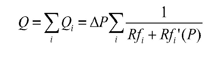
- A device dedicated to hydrocephalus has been designed in PMMA (Young Modulus of 3.3 GPa). Other plastic materials can be used like SAN, COC, PC...depending on the mechanical, chemical and biocompatibility requirements.
- The regulation profile has been set to regulate the flow rate at 20 ml/h between 10 and 35 mbar.
- The device is made of 2 plates in PMMA:
- → A membrane plate having 3 membranes, each membrane having one hole at their centres.
- → Pillars are made in the bottom plate as well as the outlet.
- The fluid pressure directly applies on the top surface of the membrane. The pillars have different heights but the membrane thickness is kept constant for the simulations. In practice the pillars heights should also be kept constant and in that case, the thickness of the membranes is variable. Grey arrows indicate the flow direction. A valve of the later device according to the seventh embodiment of the present invention is illustrated
Figure 13a . - A PMMA device having 4 valves is proposed. The table 2 summarizes the main dimensions of the device.
Table 2: Membrane diameter (um) Membrane thickness (um) Gap (um) Hole diameter (um) Pillar diameter (um) 2800 60 29.6 41.5 150 4000 60 20.5 30 150 4700 60 29.3 42 150 5200 60 27 54.9 150 - The surface of the device is about 3 times smaller than the similar device made of a single membrane in silicon.
- The flow characteristic has been simulated and the graph flow vs pressure is shown
Figure 16 . - Another example of flow characteristic including a peak of flow rate at low pressure can be proposed for hydrocephalus.
- The critical dimensions of the device are shown in the table 3:
Table 3: Membrane diameter (um) Membrane thickness (um) Gap (um) Hole diameter (um) Pillar diameter (um) 2800 60 29.6 41.8 150 4000 60 20.5 23.3 150 4700 60 29.2 46 150 5500 60 28 100 150 - The flow characteristic is shown in the following
Figure 17 . - The surface of the device is not optimised. The following example shows another flow regulator for hydrocephalus having a
surface 5 times smaller than the device made of a single membrane in silicon. Only 3 valves are used for the later device, but both the membrane thickness and the gap have been varied. - The table 4 gives the main dimensions of the device. The flow rate versus reservoir pressure is shown
Figure 18 .Table 4: Membrane diameter (um) Membrane thickness (um) Gap (um) Hole diameter (um) Pillar diameter (um) 3000 80 20 50 150 4000 35 40 70 150 4400 60 24 50 150 - The flow regulator can be used for pain management. Smaller flow rates are expected, typically 1 ml per hour or less. To avoid overdoses, the device should be a shut-off valve at high pressure.
- A device is proposed below for a flow regulation at 1 ml/h between 100 and 350 mbar. The flow vanishes at 450 mbar.
- The main dimensions are proposed in the table 5 hereafter:
Table 5: Membrane diameter (um) Membrane thickness (um) Gap (um) Hole diameter (um) Pillar diameter (um) 1250 30 14 10 80 1300 30 10.2 7 80 1380 30 10.3 7.5 80 1450 30 10.3 7.6 80 1550 30 11 8 100 - The flow characteristic is shown
Figure 19 . - The very small dimensions of the holes indicate that this design is not well adapted to low flow rate because the machining tolerances of the holes limit strongly the flow rate accuracy of the device.
- This example illustrates the interest of the fifth or sixth embodiment of the present invention (a device having channels in the substrate to generate the flow restriction instead of tiny holes) for low flow rate regulation.
- These low flow rate devices according to the fifth or sixth embodiments include membranes without holes, a substrate with through holes and channels, and finally a bottom plate having though holes for both inlets and outlet.
- For the previous application that requires a flow regulation at 1 ml/h, the fluidic restriction of the membrane holes should be simply replaced by the equivalent fluidic resistances of the channels in the bottom or pillar plate or by external flow restrictors.
- According to the design rules of the fifth and the sixth embodiments of the present invention stating that all flow resistances except the valves and the channels should be negligible, the other characteristics of the flow regulator presented in the table 5 like the membrane thicknesses and diameters, pillar heights and positions can be directly used for this device.
- The flow regulators previously exposed can be embedded into an implantable pump that contains:
- o A titanium housing
- o A drug reservoir
- o Filling ports for the drug
- o A catheter port
- o A catheter access port for bolus injection
- o A pump drive
- o A temperature sensor
- o A flow regulator
- o A filter (e.g. bacterial filter with pore size of 0.22 micron)
- o A controlled valve
- o Batteries to power the valve, the temperature sensor and the pressure sensor
- o Wireless system to power the pressure sensor and the temperature sensor
- o Alarm system that indicates:
- ■ Low batteries
- ■ Empty drug reservoir
- ■ Over or under pressures (out of the regulated pressure range)
- ■ Membrane Break
- ■ Overheating
- The flow regulator according to the present invention offers in particular the following advantages:
- → Lower risks of under and over dose due to pressure changes (climbing, diving...)
- → No risk of explosion if no gas propeller is used
- → Lower risk during the fill / refill procedure
- → No risk of overdose during impact to the body in the pump of the pump
- The invention is of course not limited to the above cited examples and related figures. There is for instance no limitation to the number and the distribution of the valves, through holes, pillars and the channels. The shapes of the pillars, stress limiter features, vias, membranes and pads for the anti-bonding layer or channels are not limited to the above cited examples.
Claims (22)
- Flow regulator comprising a fluid inlet adapted to be connected to a fluid reservoir and a fluid outlet adapted to be connected to a delivery location, said regulator comprising a rigid substrate and a flexible membrane tightly linked together in predefined linking areas so as to define a cavity there between, said cavity communicating with said fluid outlet and with said fluid inlet, said substrate and/or said membrane furthermore having at least one through hole contiguous with said cavity, to define a pathway for a fluid from said fluid inlet to said cavity, said flexible membrane being able to come into contact with at least a part of said substrate, within said cavity and with a portion including said through hole defining thereby a valve, in case a pressure is applied on said external surface that is larger than a predefined threshold value, which results in hindering a fluid from flowing through said through hole and said valve, wherein said substrate and/or said membrane comprises a pillar located in said cavity with a height which is equal or less than the cavity height and which forms a part of said valve.
- Flow regulator according to claim 1, wherein said external surface of said membrane is adapted to be connected to said fluid reservoir and to be displaced by the fluid pressure of said fluid reservoir.
- Flow regulator according to claim 1 wherein said through hole is located within said pillar.
- Flow regulator according to claim 3 wherein said substrate comprises one pillar plate and one bottom plate, said pillar plate being located between the cavity and said bottom plate, and wherein said bottom plate comprises through holes communicating with the though holes of the pillar plate.
- Flow regulator according to claim 3, wherein at least a flow restrictor is communicating with at least one of said through holes of the pillar plate or the bottom plate.
- Flow regulator according to claim 3 wherein the interface between said pillar plate and said bottom plate contains a channel plane in which at least one channel is defined, said channel communicating with said through holes of the pillar plate and said through holes of the bottom plates.
- Flow regulator according to claim 5, wherein said channel has a fluidic resistance larger than the other parts of the fluidic pathway in a predefined range of pressure.
- Flow regulator according to claim 5 wherein said interface is a layer of SOI.
- Flow regulator according to one of the previous claims wherein said flexible membrane has a variable thickness in such a way as to define a recess above the cavity.
- Flow regulator according any of the previous claims, wherein at least one valve is a shut-off valve.
- Flow regulator according any of the previous claims, wherein at least one valve is a check valve.
- Flow regulator according to one of the previous claims, comprising an anti-bonding layer on the flexible part of the membrane and / or on the rigid substrate or on both.
- Flow regulator according to one of the previous claims, comprising a thin resilient polymeric layer onto the flexible membrane.
- Flow regulator according to one of the previous claims, comprising a pressure sensor.
- Flow regulator according to one of the previous claims, comprising a filter.
- Flow regulator according to one of the previous claims, wherein the surfaces are coated with hydrophilic and / or anticorrosive agents.
- Flow regulator according to one of the previous claims, comprising a resilient and removable film with openings on the bottom plate back-side.
- Flow regulator according to one of the previous claims and comprising a full pillar, i.e. devoid of any through hole.
- Flow regulator according to claim 18 wherein said full pillar is not forming part of a valve.
- Flow regulator according to one of the previous claims wherein said membrane is centred on said through hole.
- Flow regulator according to claim 17 comprising several through holes and several membranes, each of said membranes being centred on one of said through holes.
- Flow regulator according to one of the previous claims comprising an actuator adapted to exert pressure on at least one of said membranes.
Priority Applications (10)
| Application Number | Priority Date | Filing Date | Title |
|---|---|---|---|
| EP20100153449 EP2359886A1 (en) | 2010-02-12 | 2010-02-12 | Micromechanic passive flow regulator |
| EP11710307.7A EP2533833B1 (en) | 2010-02-12 | 2011-02-07 | Micromechanic passive flow regulator |
| JP2012552504A JP5726907B2 (en) | 2010-02-12 | 2011-02-07 | Micromechanical passive flow regulator |
| BR112012019771A BR112012019771A2 (en) | 2010-02-12 | 2011-02-07 | micromechanical passive flow regulator. |
| CN201180007974.7A CN102762242B (en) | 2010-02-12 | 2011-02-07 | Micromachine passive flux actuator |
| US13/578,711 US8790318B2 (en) | 2010-02-12 | 2011-02-07 | Micromechanic passive flow regulator |
| CA 2789644 CA2789644A1 (en) | 2010-02-12 | 2011-02-07 | Micromechanic passive flow regulator |
| RU2012136065/14A RU2012136065A (en) | 2010-02-12 | 2011-02-07 | MICROMECHANICAL PASSIVE FLOW REGULATOR |
| PCT/IB2011/050514 WO2011098946A1 (en) | 2010-02-12 | 2011-02-07 | Micromechanic passive flow regulator |
| US14/444,902 US9867935B2 (en) | 2010-02-12 | 2014-07-28 | Micromechanic passive flow regulator |
Applications Claiming Priority (1)
| Application Number | Priority Date | Filing Date | Title |
|---|---|---|---|
| EP20100153449 EP2359886A1 (en) | 2010-02-12 | 2010-02-12 | Micromechanic passive flow regulator |
Publications (1)
| Publication Number | Publication Date |
|---|---|
| EP2359886A1 true EP2359886A1 (en) | 2011-08-24 |
Family
ID=42537757
Family Applications (2)
| Application Number | Title | Priority Date | Filing Date |
|---|---|---|---|
| EP20100153449 Withdrawn EP2359886A1 (en) | 2010-02-12 | 2010-02-12 | Micromechanic passive flow regulator |
| EP11710307.7A Active EP2533833B1 (en) | 2010-02-12 | 2011-02-07 | Micromechanic passive flow regulator |
Family Applications After (1)
| Application Number | Title | Priority Date | Filing Date |
|---|---|---|---|
| EP11710307.7A Active EP2533833B1 (en) | 2010-02-12 | 2011-02-07 | Micromechanic passive flow regulator |
Country Status (8)
| Country | Link |
|---|---|
| US (2) | US8790318B2 (en) |
| EP (2) | EP2359886A1 (en) |
| JP (1) | JP5726907B2 (en) |
| CN (1) | CN102762242B (en) |
| BR (1) | BR112012019771A2 (en) |
| CA (1) | CA2789644A1 (en) |
| RU (1) | RU2012136065A (en) |
| WO (1) | WO2011098946A1 (en) |
Cited By (5)
| Publication number | Priority date | Publication date | Assignee | Title |
|---|---|---|---|---|
| EP2754935A1 (en) * | 2013-01-10 | 2014-07-16 | Debiotech S.A. | Adjustable passive flow regulator |
| EP2956190A4 (en) * | 2013-02-15 | 2016-08-24 | Repro Med Systems Inc | Multi-flow universal tubing set |
| US9867935B2 (en) | 2010-02-12 | 2018-01-16 | Debiotech S.A. | Micromechanic passive flow regulator |
| WO2018184717A3 (en) * | 2017-04-06 | 2018-12-27 | Christoph Miethke Gmbh & Co. Kg | FLUSSREDUKTOR |
| US12005215B2 (en) | 2017-04-06 | 2024-06-11 | Christoph Miethke Gmbh & Co Kg | Flow reducer |
Families Citing this family (40)
| Publication number | Priority date | Publication date | Assignee | Title |
|---|---|---|---|---|
| JP3143657B2 (en) | 1993-03-29 | 2001-03-07 | 豊田工機株式会社 | Grinding equipment |
| US7806001B1 (en) * | 2007-06-05 | 2010-10-05 | Orbital Research Inc. | Multi-diaphragm pressure sensors |
| US20150258273A1 (en) * | 2011-08-31 | 2015-09-17 | Forrest W. Payne | Electrochemically-Actuated Microfluidic Devices |
| ES2766779T3 (en) * | 2012-10-01 | 2020-06-15 | Niclas Roxhed | Cerebrospinal fluid bypass for hydrocephalus treatment |
| US9295389B2 (en) | 2012-12-17 | 2016-03-29 | Novartis Ag | Systems and methods for priming an intraocular pressure sensor in an intraocular implant |
| US9572712B2 (en) | 2012-12-17 | 2017-02-21 | Novartis Ag | Osmotically actuated fluidic valve |
| US9528633B2 (en) | 2012-12-17 | 2016-12-27 | Novartis Ag | MEMS check valve |
| US9283114B2 (en) | 2013-08-24 | 2016-03-15 | Novartis Ag | Systems and methods for priming a microfluidic chamber |
| US20150057594A1 (en) | 2013-08-24 | 2015-02-26 | Alcon Research, Ltd. | Bubble-free microfluidic valve systems and methods |
| WO2015174330A1 (en) * | 2014-05-13 | 2015-11-19 | 株式会社村田製作所 | Valve and fluid control device |
| CN104315232B (en) * | 2014-08-20 | 2018-01-09 | 中国检验检疫科学研究院 | Microfluid micro-valve drive device |
| US9527731B2 (en) * | 2014-10-15 | 2016-12-27 | Nxp Usa, Inc. | Methodology and system for wafer-level testing of MEMS pressure sensors |
| CN104728492A (en) * | 2015-01-27 | 2015-06-24 | 东南大学 | Minitype passive flow regulating valve and manufacturing technique thereof |
| JP6900360B2 (en) | 2015-07-08 | 2021-07-07 | デビオテック ソシエテ アノニム | Systems and methods for cleaning filters |
| US10722849B2 (en) | 2016-02-12 | 2020-07-28 | Nitto Denko Corporation | Pressure sensitive graphene-based valve element |
| WO2017195475A1 (en) * | 2016-05-09 | 2017-11-16 | 株式会社村田製作所 | Valve, fluid control device, and blood-pressure monitor |
| WO2018064775A1 (en) * | 2016-10-07 | 2018-04-12 | Xinyu Liu | A microfluidic analytical platform for autonomous immunoassays |
| BR112019011871A2 (en) * | 2016-12-13 | 2019-10-29 | The Board Of Regents Of The Univ Texas System | vascular tissue perfusion apparatus, systems and methods |
| US10709879B2 (en) * | 2017-03-29 | 2020-07-14 | Wisconsin Alumni Research Foundation | Cerebrospinal-fluid shunt valve system |
| RU2656038C1 (en) * | 2017-07-21 | 2018-05-30 | федеральное государственное бюджетное образовательное учреждение высшего образования "Уфимский государственный авиационный технический университет" | Device for adjustment of the monitoring gas flow |
| CN107818931B (en) * | 2017-09-30 | 2021-10-19 | 厦门市三安光电科技有限公司 | Transfer method and transfer device for semiconductor micro-components |
| WO2019159121A1 (en) | 2018-02-16 | 2019-08-22 | Debiotech S.A. | Status indicator of a drug delivery system |
| EP3593832A1 (en) | 2018-07-11 | 2020-01-15 | Debiotech S.A. | Drug delivery system |
| US12070571B2 (en) | 2018-07-11 | 2024-08-27 | Debiotech S.A. | Drug delivery system |
| CN113423983B (en) * | 2019-02-17 | 2024-05-31 | 科梅特洛有限公司 | Float valve system and method for controlling the level of a liquid in a container |
| CN109821100B (en) * | 2019-03-01 | 2021-04-30 | 浙江师范大学 | Step-by-step booster-type pneumatic infusion device |
| EP3714822B1 (en) | 2019-03-25 | 2023-01-18 | Erbe Elektromedizin GmbH | Fluid control assembly for a medical device |
| CN110132539B (en) * | 2019-06-12 | 2024-01-26 | 桂林电子科技大学 | Experimental platform for non-contact measurement of axisymmetric fluid film morphology |
| CN119641991A (en) | 2019-07-26 | 2025-03-18 | 朗姆研究公司 | Nonelastomer, non-polymer, non-metallic film valve for semiconductor processing equipment |
| JP7506191B2 (en) * | 2020-05-28 | 2024-06-25 | ミネトロニクス ニューロ インコーポレイテッド | Filtration system and filtration manifold for use with the filtration system - Patents.com |
| DE102020134312B3 (en) * | 2020-12-18 | 2022-01-05 | Christoph Miethke Gmbh & Co Kg | Adjustable implantable choke |
| US20240068583A1 (en) * | 2021-01-08 | 2024-02-29 | Novoheart International Limited | Low pressure valve assemblies |
| CN113028095B (en) * | 2021-04-06 | 2024-06-18 | 常州天目智能科技有限公司 | Throttling device based on shape memory alloy and method for controlling opening of channel |
| CN113251207B (en) * | 2021-05-13 | 2022-09-23 | 哈尔滨工业大学 | Pneumatic shuttle valve based on PDMS material and control method |
| US20250135101A1 (en) * | 2022-02-17 | 2025-05-01 | Aita Bio Inc. | Mems micropump with piezoelectric active valve that remains closed following micropump power loss |
| TWI800431B (en) * | 2022-07-26 | 2023-04-21 | 郭凡慶 | Hydrocephalus flow regulating device |
| DE102023207100A1 (en) * | 2023-07-26 | 2025-01-30 | Robert Bosch Gesellschaft mit beschränkter Haftung | Method for producing a microelectromechanical device and microelectromechanical device |
| US20250102074A1 (en) * | 2023-09-25 | 2025-03-27 | Applied Materials, Inc. | Proportional fluid flow valve and methods of operating thereof |
| US20250102072A1 (en) * | 2023-09-26 | 2025-03-27 | Applied Materials, Inc. | Fluid flow valve and methods of operating thereof |
| CN120249024B (en) * | 2025-04-02 | 2026-01-27 | 郑州大学第一附属医院 | Medical microorganism virus detection device and method |
Citations (13)
| Publication number | Priority date | Publication date | Assignee | Title |
|---|---|---|---|---|
| US3288142A (en) | 1964-04-27 | 1966-11-29 | Hakim Salomon | Hydrocephalus shunt with spring biased one-way valves |
| US4551128A (en) | 1983-05-11 | 1985-11-05 | Salomon Hakim | Cerebrospinal fluid shunt valve |
| US4781673A (en) | 1985-12-20 | 1988-11-01 | Kabushiki Kaisha Nihon M.D.M. | Brain ventricle shunt system with flow-rate switching mechanism |
| EP0369712A2 (en) * | 1988-11-15 | 1990-05-23 | Baxter International Inc. | Fluid flow control |
| US5192265A (en) | 1990-12-10 | 1993-03-09 | Hsc Research & Development Limited Partnership | Adjustable-resistance anti-siphon device |
| DE4223067A1 (en) * | 1992-07-14 | 1994-01-20 | Juergen Dipl Ing Joswig | Micromechanical flow limiter with multilayer structure, e.g. for medical infusion system - has intermediate diaphragm layer which deflects w.r.t. amount of flowing medium, and blocks flow for large flow amounts |
| US5839467A (en) * | 1993-10-04 | 1998-11-24 | Research International, Inc. | Micromachined fluid handling devices |
| US6126628A (en) | 1997-04-22 | 2000-10-03 | Johnson & Johnson Professional, Inc. | Fluid flow limiting device |
| US6203523B1 (en) | 1998-02-02 | 2001-03-20 | Medtronic Inc | Implantable drug infusion device having a flow regulator |
| US20060206049A1 (en) * | 2005-03-14 | 2006-09-14 | Rodgers M S | MEMS flow module with piston-type pressure regulating structure |
| FR2905429A1 (en) * | 2006-09-04 | 2008-03-07 | Debiotech Sa | DEVICE FOR DELIVERING A LIQUID COMPRISING A PUMP AND A VALVE |
| WO2008094672A2 (en) * | 2007-01-31 | 2008-08-07 | Charles Stark Draper Laboratory, Inc. | Membrane-based fluid control in microfluidic devices |
| WO2009098314A1 (en) | 2008-02-09 | 2009-08-13 | Debiotech S.A. | Passive flow regulator for infusion of medicaments |
Family Cites Families (32)
| Publication number | Priority date | Publication date | Assignee | Title |
|---|---|---|---|---|
| US3401719A (en) | 1966-03-31 | 1968-09-17 | Sylvania Electric Prod | Multiple bleed valve cartridge assembly |
| US3768508A (en) | 1972-01-24 | 1973-10-30 | R Schulte | Valve for controllable release of entrapped body fluids |
| US3779274A (en) * | 1972-11-21 | 1973-12-18 | Robertshaw Controls Co | Pressure regulator |
| US4625759A (en) | 1982-11-19 | 1986-12-02 | Alan R. Krasberg | Gas reclaim back pressure regulator |
| EP0156974B1 (en) | 1983-12-08 | 1989-08-30 | Cordis Corporation | Three-stage valve for the flow control of body fluids |
| US4647013A (en) * | 1985-02-21 | 1987-03-03 | Ford Motor Company | Silicon valve |
| US4646781A (en) | 1985-05-07 | 1987-03-03 | Pacesetter Infusion, Ltd. | Diaphragm valve for medication infusion pump |
| US4846215A (en) * | 1988-06-07 | 1989-07-11 | Marathon Oil Company | Back pressure regulator |
| US5163920A (en) * | 1991-01-30 | 1992-11-17 | Infusaid Inc. | Flow regulator damper element |
| AU717626B2 (en) | 1996-10-03 | 2000-03-30 | Debiotech S.A. | Micro-machined device for fluids and method of manufacture |
| US5725017A (en) | 1997-01-27 | 1998-03-10 | Medtronic, Inc. | In-line pressure check valve for drug-delivery systems |
| DE19737781A1 (en) * | 1997-08-29 | 1999-03-11 | Robert Schoenfeld | Regulator for regulating at least one hydrostatic or aerostat pocket of a bearing, threaded spindle nut or a media flow supplied to a guide |
| DE19816283A1 (en) * | 1998-04-11 | 1999-10-14 | Festo Ag & Co | Quantity amplifier device for fluid flows |
| DE59900839D1 (en) * | 1998-05-08 | 2002-03-21 | Infineon Technologies Ag | MICRO VALVE |
| US5988211A (en) * | 1998-07-06 | 1999-11-23 | Randolph W. Cornell | I.V. flow controller |
| US6173735B1 (en) * | 1999-04-29 | 2001-01-16 | Perry Equipment Corporation | Method and apparatus for regulating gas flow |
| US6179586B1 (en) | 1999-09-15 | 2001-01-30 | Honeywell International Inc. | Dual diaphragm, single chamber mesopump |
| US6830229B2 (en) * | 2001-05-22 | 2004-12-14 | Lockheed Martin Corporation | Two-stage valve suitable as high-flow high-pressure microvalve |
| JP3756429B2 (en) * | 2001-07-12 | 2006-03-15 | Smc株式会社 | Flow control valve |
| US7367968B2 (en) * | 2003-09-05 | 2008-05-06 | Codman & Shurtleff, Inc. | Implantable pump with adjustable flow rate |
| US6986365B2 (en) * | 2003-09-30 | 2006-01-17 | Redwood Microsystems | High-flow microvalve |
| US8251981B2 (en) | 2004-06-07 | 2012-08-28 | Medtronic, Inc. | Regulator |
| US7832429B2 (en) * | 2004-10-13 | 2010-11-16 | Rheonix, Inc. | Microfluidic pump and valve structures and fabrication methods |
| US8211060B2 (en) | 2005-05-10 | 2012-07-03 | Palyon Medical (Bvi) Limited | Reduced size implantable pump |
| CN101213392B (en) | 2005-06-30 | 2012-06-27 | 皇家飞利浦电子股份有限公司 | Valve device |
| JP4325607B2 (en) * | 2005-10-05 | 2009-09-02 | パナソニック電工株式会社 | Micro regulator |
| DE102005058080B4 (en) * | 2005-12-06 | 2008-01-03 | Albert-Ludwigs-Universität Freiburg | Monitoring unit for fluid metering and microdosing |
| JP5066085B2 (en) | 2006-07-05 | 2012-11-07 | アイダエンジニアリング株式会社 | Microchannel chip and fluid transfer method |
| EP2153855A1 (en) * | 2008-08-16 | 2010-02-17 | Debiotech S.A. | Passive fluid flow regulator for constant flow rate drug delivery and corresponding drug infusion device |
| EP2359886A1 (en) | 2010-02-12 | 2011-08-24 | Debiotech S.A. | Micromechanic passive flow regulator |
| US8276618B2 (en) | 2010-05-18 | 2012-10-02 | Mindray Medical Sweden Ab | Flow restrictor and method for reducing resistance of a flow |
| US8858491B2 (en) * | 2012-05-23 | 2014-10-14 | Alcon Research, Ltd. | Pre-biased membrane valve |
-
2010
- 2010-02-12 EP EP20100153449 patent/EP2359886A1/en not_active Withdrawn
-
2011
- 2011-02-07 CN CN201180007974.7A patent/CN102762242B/en not_active Expired - Fee Related
- 2011-02-07 JP JP2012552504A patent/JP5726907B2/en not_active Expired - Fee Related
- 2011-02-07 US US13/578,711 patent/US8790318B2/en active Active
- 2011-02-07 BR BR112012019771A patent/BR112012019771A2/en not_active Application Discontinuation
- 2011-02-07 RU RU2012136065/14A patent/RU2012136065A/en not_active Application Discontinuation
- 2011-02-07 CA CA 2789644 patent/CA2789644A1/en not_active Abandoned
- 2011-02-07 EP EP11710307.7A patent/EP2533833B1/en active Active
- 2011-02-07 WO PCT/IB2011/050514 patent/WO2011098946A1/en not_active Ceased
-
2014
- 2014-07-28 US US14/444,902 patent/US9867935B2/en not_active Expired - Fee Related
Patent Citations (13)
| Publication number | Priority date | Publication date | Assignee | Title |
|---|---|---|---|---|
| US3288142A (en) | 1964-04-27 | 1966-11-29 | Hakim Salomon | Hydrocephalus shunt with spring biased one-way valves |
| US4551128A (en) | 1983-05-11 | 1985-11-05 | Salomon Hakim | Cerebrospinal fluid shunt valve |
| US4781673A (en) | 1985-12-20 | 1988-11-01 | Kabushiki Kaisha Nihon M.D.M. | Brain ventricle shunt system with flow-rate switching mechanism |
| EP0369712A2 (en) * | 1988-11-15 | 1990-05-23 | Baxter International Inc. | Fluid flow control |
| US5192265A (en) | 1990-12-10 | 1993-03-09 | Hsc Research & Development Limited Partnership | Adjustable-resistance anti-siphon device |
| DE4223067A1 (en) * | 1992-07-14 | 1994-01-20 | Juergen Dipl Ing Joswig | Micromechanical flow limiter with multilayer structure, e.g. for medical infusion system - has intermediate diaphragm layer which deflects w.r.t. amount of flowing medium, and blocks flow for large flow amounts |
| US5839467A (en) * | 1993-10-04 | 1998-11-24 | Research International, Inc. | Micromachined fluid handling devices |
| US6126628A (en) | 1997-04-22 | 2000-10-03 | Johnson & Johnson Professional, Inc. | Fluid flow limiting device |
| US6203523B1 (en) | 1998-02-02 | 2001-03-20 | Medtronic Inc | Implantable drug infusion device having a flow regulator |
| US20060206049A1 (en) * | 2005-03-14 | 2006-09-14 | Rodgers M S | MEMS flow module with piston-type pressure regulating structure |
| FR2905429A1 (en) * | 2006-09-04 | 2008-03-07 | Debiotech Sa | DEVICE FOR DELIVERING A LIQUID COMPRISING A PUMP AND A VALVE |
| WO2008094672A2 (en) * | 2007-01-31 | 2008-08-07 | Charles Stark Draper Laboratory, Inc. | Membrane-based fluid control in microfluidic devices |
| WO2009098314A1 (en) | 2008-02-09 | 2009-08-13 | Debiotech S.A. | Passive flow regulator for infusion of medicaments |
Non-Patent Citations (5)
| Title |
|---|
| "Actuator Workshop (Hilton Head '88), Hilton Head Island, SC", SOLID-STATE SENS, 6 June 1988 (1988-06-06), pages 136 - 139 |
| B. YANG; Q. LIN: "A Planar Compliance-Based Self-Adaptive Microfluid Variable Resistor", JOURNAL OF MICROELECTROMECHANICAL SYSTEMS, vol. 16, 2007, pages 411 - 419 |
| E. P. KARTALOV; C.WALKER; C. R. TAYLOR; W. F. ANDERSON; A. SCHERER: "Microfluidic vias enable nested bioarrays and autoregulatory devices in Newtonian fluids", PROC. NAT. ACAD. SCI., vol. 103, 2006, pages 12280 - 12284 |
| GROISMAN ET AL., SCIENCE, vol. 300, 2003, pages 955 - 958 |
| S. PARK; W. H.KO; J. M. PRAHL: "A constant flow-rate microvalve actuator based on silicon and micromachining technology", TECH. DIG., 1988 |
Cited By (7)
| Publication number | Priority date | Publication date | Assignee | Title |
|---|---|---|---|---|
| US9867935B2 (en) | 2010-02-12 | 2018-01-16 | Debiotech S.A. | Micromechanic passive flow regulator |
| EP2754935A1 (en) * | 2013-01-10 | 2014-07-16 | Debiotech S.A. | Adjustable passive flow regulator |
| WO2014108860A1 (en) * | 2013-01-10 | 2014-07-17 | Debiotech S.A. | Adjustable passive flow regulator |
| US9971358B2 (en) | 2013-01-10 | 2018-05-15 | Debiotech S.A. | Adjustable passive flow regulator |
| EP2956190A4 (en) * | 2013-02-15 | 2016-08-24 | Repro Med Systems Inc | Multi-flow universal tubing set |
| WO2018184717A3 (en) * | 2017-04-06 | 2018-12-27 | Christoph Miethke Gmbh & Co. Kg | FLUSSREDUKTOR |
| US12005215B2 (en) | 2017-04-06 | 2024-06-11 | Christoph Miethke Gmbh & Co Kg | Flow reducer |
Also Published As
| Publication number | Publication date |
|---|---|
| EP2533833B1 (en) | 2019-04-03 |
| JP5726907B2 (en) | 2015-06-03 |
| US20150005717A1 (en) | 2015-01-01 |
| JP2013519422A (en) | 2013-05-30 |
| CA2789644A1 (en) | 2011-08-18 |
| RU2012136065A (en) | 2014-03-20 |
| CN102762242B (en) | 2015-07-29 |
| US8790318B2 (en) | 2014-07-29 |
| US9867935B2 (en) | 2018-01-16 |
| CN102762242A (en) | 2012-10-31 |
| US20120316492A1 (en) | 2012-12-13 |
| WO2011098946A1 (en) | 2011-08-18 |
| BR112012019771A2 (en) | 2016-05-17 |
| EP2533833A1 (en) | 2012-12-19 |
Similar Documents
| Publication | Publication Date | Title |
|---|---|---|
| EP2533833B1 (en) | Micromechanic passive flow regulator | |
| EP2331169B1 (en) | Passive fluid flow regulator for the administration of medicaments with constant flow rate and drug infusion device comprising the same. | |
| CN102413866B (en) | Passive fluid flow regulator | |
| EP2754935A1 (en) | Adjustable passive flow regulator | |
| CN105874254A (en) | Diaphragm check valve and manufacturing method thereof | |
| Dumont-Fillon et al. | Design and characterization of 3-stack MEMS-based passive flow regulators for implantable and ambulatory infusion pumps | |
| US12420011B2 (en) | Devices and methods for flow restriction in a microfluidic circuit for drug delivery | |
| Schwerdt et al. | Hydrogel check valve with non-zero cracking pressure for use as a potential alternative hydrocephalus treatment method | |
| Evans | Valve regulated implantable intrathecal drug delivery for chronic pain management |
Legal Events
| Date | Code | Title | Description |
|---|---|---|---|
| PUAI | Public reference made under article 153(3) epc to a published international application that has entered the european phase |
Free format text: ORIGINAL CODE: 0009012 |
|
| PUAI | Public reference made under article 153(3) epc to a published international application that has entered the european phase |
Free format text: ORIGINAL CODE: 0009012 |
|
| AK | Designated contracting states |
Kind code of ref document: A1 Designated state(s): AT BE BG CH CY CZ DE DK EE ES FI FR GB GR HR HU IE IS IT LI LT LU LV MC MK MT NL NO PL PT RO SE SI SK SM TR |
|
| AX | Request for extension of the european patent |
Extension state: AL BA RS |
|
| STAA | Information on the status of an ep patent application or granted ep patent |
Free format text: STATUS: THE APPLICATION IS DEEMED TO BE WITHDRAWN |
|
| 18D | Application deemed to be withdrawn |
Effective date: 20120225 |