EP2310271B1 - Visual landing aids - Google Patents
Visual landing aids Download PDFInfo
- Publication number
- EP2310271B1 EP2310271B1 EP09784892.3A EP09784892A EP2310271B1 EP 2310271 B1 EP2310271 B1 EP 2310271B1 EP 09784892 A EP09784892 A EP 09784892A EP 2310271 B1 EP2310271 B1 EP 2310271B1
- Authority
- EP
- European Patent Office
- Prior art keywords
- aircraft
- deck
- platform
- visual
- lights
- Prior art date
- Legal status (The legal status is an assumption and is not a legal conclusion. Google has not performed a legal analysis and makes no representation as to the accuracy of the status listed.)
- Active
Links
- 230000000007 visual effect Effects 0.000 title claims description 30
- 239000003550 marker Substances 0.000 claims description 15
- 241000985905 Candidatus Phytoplasma solani Species 0.000 claims description 4
- 238000000034 method Methods 0.000 claims description 4
- 238000005096 rolling process Methods 0.000 claims description 3
- 230000033001 locomotion Effects 0.000 description 13
- 238000013459 approach Methods 0.000 description 12
- 239000011295 pitch Substances 0.000 description 9
- 238000000926 separation method Methods 0.000 description 4
- 230000008901 benefit Effects 0.000 description 2
- 230000000994 depressogenic effect Effects 0.000 description 2
- 238000005286 illumination Methods 0.000 description 2
- 241000272470 Circus Species 0.000 description 1
- 230000003466 anti-cipated effect Effects 0.000 description 1
- 238000003491 array Methods 0.000 description 1
- 239000000969 carrier Substances 0.000 description 1
- 239000012141 concentrate Substances 0.000 description 1
- 238000010586 diagram Methods 0.000 description 1
- 230000000694 effects Effects 0.000 description 1
- 230000003628 erosive effect Effects 0.000 description 1
- 238000009434 installation Methods 0.000 description 1
- 238000012423 maintenance Methods 0.000 description 1
- 230000003340 mental effect Effects 0.000 description 1
- 230000004297 night vision Effects 0.000 description 1
- 230000003287 optical effect Effects 0.000 description 1
- 238000004088 simulation Methods 0.000 description 1
Images


Classifications
-
- B—PERFORMING OPERATIONS; TRANSPORTING
- B64—AIRCRAFT; AVIATION; COSMONAUTICS
- B64F—GROUND OR AIRCRAFT-CARRIER-DECK INSTALLATIONS SPECIALLY ADAPTED FOR USE IN CONNECTION WITH AIRCRAFT; DESIGNING, MANUFACTURING, ASSEMBLING, CLEANING, MAINTAINING OR REPAIRING AIRCRAFT, NOT OTHERWISE PROVIDED FOR; HANDLING, TRANSPORTING, TESTING OR INSPECTING AIRCRAFT COMPONENTS, NOT OTHERWISE PROVIDED FOR
- B64F1/00—Ground or aircraft-carrier-deck installations
- B64F1/18—Visual or acoustic landing aids
- B64F1/20—Arrangement of optical beacons
-
- G—PHYSICS
- G02—OPTICS
- G02B—OPTICAL ELEMENTS, SYSTEMS OR APPARATUS
- G02B27/00—Optical systems or apparatus not provided for by any of the groups G02B1/00 - G02B26/00, G02B30/00
- G02B27/01—Head-up displays
-
- G—PHYSICS
- G05—CONTROLLING; REGULATING
- G05D—SYSTEMS FOR CONTROLLING OR REGULATING NON-ELECTRIC VARIABLES
- G05D1/00—Control of position, course, altitude or attitude of land, water, air or space vehicles, e.g. using automatic pilots
- G05D1/04—Control of altitude or depth
- G05D1/06—Rate of change of altitude or depth
- G05D1/0607—Rate of change of altitude or depth specially adapted for aircraft
- G05D1/0653—Rate of change of altitude or depth specially adapted for aircraft during a phase of take-off or landing
- G05D1/0676—Rate of change of altitude or depth specially adapted for aircraft during a phase of take-off or landing specially adapted for landing
- G05D1/0684—Rate of change of altitude or depth specially adapted for aircraft during a phase of take-off or landing specially adapted for landing on a moving platform, e.g. aircraft carrier
-
- G—PHYSICS
- G02—OPTICS
- G02B—OPTICAL ELEMENTS, SYSTEMS OR APPARATUS
- G02B27/00—Optical systems or apparatus not provided for by any of the groups G02B1/00 - G02B26/00, G02B30/00
- G02B27/01—Head-up displays
- G02B27/0101—Head-up displays characterised by optical features
- G02B2027/0141—Head-up displays characterised by optical features characterised by the informative content of the display
Definitions
- the present invention relates to visual landing aids (VLAs) and more particularly to a visual aid for the pilots of aircraft approaching to land on moving platforms, notably vessels at sea such as aircraft carriers or other ships which can accommodate aircraft landings of the type more particularly described herein.
- VLAs visual landing aids
- the invention has been conceived particularly, though not exclusively, as an aid for use in executing shipboard rolling vertical landings.
- the so-called rolling vertical landing (RVL) is a type of landing executed by vectored-thrust vertical/short takeoff and landing (V/STOL) and short takeoff and vertical landing (STOVL) aircraft as an alternative to a normal vertical landing, in which the aircraft approaches at an angle to the ground and at relatively slow speed (in comparison to conventional fixed-wing landings) under a combination of jet-borne and wing-borne lift.
- Aircraft of this class include the well known V/STOL Harrier and Sea Harrier "jump jet" variants, and the STOVL F-35B variant of the Lightning II yet to enter service.
- the RVL was developed originally as a manoeuvre for landing on unprepared areas in land-based operations so that debris disturbed by the jet efflux would tend to be blown behind the aircraft and not into the engine intakes. It is also considered to be a useful technique for shipboard operations, however, due to the ability to land with a higher aircraft weight than would be possible in the same meteorological conditions if a vertical landing was to be used, or to land at the same weight but with a reduced power setting as compared to the vertical landing thereby potentially increasing engine life. Other benefits can include a reduction in the erosion of deck coverings by engine exhaust as compared to vertical landings.
- RVLs While conceived with shipboard RVLs by V/STOL and STOVL aircraft in mind, however, the present invention may also find application as an aid for conventional (wire-arrested) fixed wing carrier-borne landings which are typically conducted with shallower approach angles and at substantially higher speeds than RVLs, and also for helicopter landings if not performed vertically.
- IFLOLS Improved Fresnel Lens Optical Landing System
- This comprises a set of lights located on the deck offset laterally from the runway and directed towards approaching aircraft.
- This can be stabilised for pitch, roll and heave of the deck with the apparatus being tilted on gimbals as required to maintain its indication of the correct glideslope.
- deck spotting Inadvertently reacting instead to deck motion, known as "deck spotting". It is also expensive to maintain due to the number of moving parts, and occupies useful deck space.
- the present invention seeks to provide a VLA which imposes a lower mental workload on the pilot and consequently involves less of a training burden than the IFLOLS, does not require him to scan laterally away from the runway, and in a preferred embodiment involves no moving parts and does not occupy otherwise useful deck space.
- US4259658A discloses an aircraft take-off and landing system where electromagnetic pencil beams are projected from fixed positions on a ship landing deck which appear differently to a pilot depending on his position relative to a glideslope which moves with the deck.
- the present invention is predicated on the provision of a visual aim point on the platform which when in registry with a visual marker on or in the aircraft indicates that the aircraft is on a specified glideslope to touch down at a point related to the aim point.
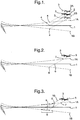
- Figure 1 indicates in full line the deck 1 of an aircraft carrier in a nominal level (equilibrium) condition and the line 2 indicates the glideslope down which an aircraft 3 has to fly with the deck in this condition to arrive at a specified mainwheel touchdown point 4 at a specified approach angle.
- the vessel pitches with the bow down and the stern up so that the deck is now in the attitude indicated in chain line, 1A.
- the touchdown point 4 is accordingly now above its position in space with the level deck and the glideslope down which the aircraft would have to fly in this condition to arrive at the same point 4 at the specified approach angle is indicated by the line 2A.
- the vessel pitches with the bow up and the stern down so that the deck is now
- Figure 2 illustrates an alternative approach where instead of requiring touchdown at a single fixed point on the deck 1 the glideslope 5 is itself stabilised in space. It follows that for the illustrated range of deck excursions there will be a range of possible touchdown points depending on where the deck intersects the glideslope at the actual moment of touchdown. For example with a level deck 1 touchdown will occur at point 6, with the deck raised as at 1A touchdown will occur further aft at point 7, and with the deck depressed as at 1B touchdown will occur further forward at point 8.
- the invention resides in a visual aid for the pilot of an aircraft approaching to land on a moving platform comprising means for defining a visual aim point on the platform and means for adjusting the apparent position of such visual aim point along the platform in response to excursions of the platform in the vertical sense so that registry of the visual aim point with an associated visual marker on or in the aircraft at any time indicates that the aircraft is on substantially the same specified glideslope fixed in space relative to the overall platform irrespective of such excursions thereof.
- the visual aim point in such an arrangement could be represented by a distinctive object which is physically translated back and forth along the platform as required in use of the aid, or even an object which is moved vertically up and down from a fixed position on the platform (but would have to be fully retracted at the moment of touchdown or would represent a collision hazard).
- the aid comprises an array of lights which are distributed along the platform and arranged to be lit selectively to indicate the position of the aim point at any time.
- the aim point indicator lights are arranged in a row or parallel rows along the platform and controlled such that the light in the or each row which is nearest to the intended aim point at any time is lit.
- those lights are arranged in a row or parallel rows along the platform and controlled such that a single light is lit in the or each row when the intended aim point is within a specified distance of that light and two successive lights are lit in the or each row when the intended aim point is within a specified distance of the mid point between those two lights.
- lights may also be lit to indicate the effective limits of the array at any time.
- An array of aim point indicator lights may also extend along a length of the platform such that different longitudinal sections thereof are capable of functioning to provide an adjustable aim point for a plurality of specified glideslopes fixed in space in different positions along the platform.
- the associated visual marker on or in the aircraft will be presented in a head up display (HUD) or helmet mounted display (HMD) and comprise a marker representing a depression angle from the horizon equal to the specified glideslope angle.
- HUD head up display
- HMD helmet mounted display
- Other arrangements are possible, however, such as an equivalent marker in a cockpit display from a forward-looking camera or simply a physical marker on part of the aircraft structure which is positioned relative to the pilot eye-point at the required fixed depression from the horizon when the aircraft is in the correct approach attitude.
- the invention resides in a visual aid for the pilot of an aircraft approaching to land on the deck of an aircraft carrier or the like vessel comprising means for defining a visual indication on the deck and means for adjusting the apparent position of such visual indication along the deck in response to excursions of the vessel in pitch so that when viewed along a specified sightline from the aircraft said indication corresponds to the aftmost limit at which the aircraft will safely clear the stern of the vessel when following a specified glideslope parallel to said sightline irrespective of such excursions of the vessel.
- the invention resides in a method of approaching to land an aircraft on a moving platform by use of a visual aid as defined above.
- Figure 3 illustrates the principle of the invention schematically and not to scale (and wherein for ease of illustration the depicted glideslope is much steeper than that which can be expected in practice), as implemented with an array of indicator lights;
- Figure 4 is a schematic block diagram of the control system for the indicator lights in a VLA according to the invention.
- Figure 5 is a plan view of one embodiment of an indicator light array for use in a VLA according to the invention.
- Figure 6 indicates an example of the pilot's eye view when using a VLA according to the invention.
- Figure 7 illustrates an optional lighting logic for use in a VLA according to the invention.
- the aircraft 3 is shown with a specified mainwheel glideslope 5 fixed in space relative to the deck 1 and a possible range of touchdown points such as 6, 7 and 8 corresponding to a range of vertical deck excursions similarly to Figure 2 .
- a possible range of touchdown points such as 6, 7 and 8 corresponding to a range of vertical deck excursions similarly to Figure 2 .
- Let into the deck along a length forwardly offset from the touchdown point range is an array of aim point indicator lights 9.
- the pilot observes the lights 9 in conjunction with a marker presented in, say, a HUD or HMD and representing a depression angle from the horizon equal to the angle of the glideslope 5, or in other words along a sightline 10 parallel to the glideslope.
- the central light is lit, at the maximum upward deck excursion (1A) with which the system is intended to operate the rearmost light is lit, at the maximum downward deck excursion (1B) with which the system is intended to be used the foremost light is lit, and so on.
- the aim point represented by the illuminated light moves relative to the deck as the deck moves up and down with ship pitch, heave etc it remains in a substantially fixed position with respect to an observer in the plane of the glideslope 5 (i.e. as viewed along the sightline 10), and by controlling the aircraft to keep whichever light is lit in registry with his specified HUD/HMD marker the pilot can be confident that the aircraft is correctly following the glideslope 5.
- Figure 5 illustrates one practical example of an aim point light array for use in a VLA according to the invention.
- the indicator lights 9 are arranged in pairs to either side of the runway centreline, in a "tramline” arrangement, and conventional "tramline” lights (typically at greater longitudinal spacings than the aim point lights 9) are also seen at 14.
- Extra lateral lights as shown at 15 can also be provided to indicate the limits of the aim point array.
- Figure 6 indicates an example of the pilot's eye view when approaching to land on an aircraft carrier and using an aim point light array similar to that of Figure 5 .
- "Tramlines" 16 are painted on the deck to either side of the runway centreline. Lights similar to those indicated at 14 in Figure 5 will be spaced along these "tramlines” but are not shown separately in Figure 6 .
- Two lateral rows of limit lights 15 are however shown and between them a pair of illuminated aim point lights 9 which in this case are bar shaped, the other members of the aim point light array which are not illuminated at the instant depicted in Figure 6 not being shown.
- HUD symbology visible to the pilot is also shown including a ship referenced velocity vector symbol (circle) 17 and a marker (pair of bars) 18 representing a depression angle from the horizon corresponding to the desired glideslope angle; (other conventional HUD symbology which will usually be present in the pilot's display is omitted for ease of illustration).
- the invention can be used with any practical glideslope angle which may be chosen in any case with regard to the operational requirements, prevailing meteorological conditions, aircraft performance and characteristics etc. In the example of Figure 6 , however, a 6° angle is assumed, which is considered to be a practical option for shipboard RVLs.
- the HUD 6° marker 18 is shown to be in near registry with the illuminated aim point lights 9 showing that the aircraft is established on the correct glideslope to within an acceptable degree of error.
- the VLA according to the invention and exemplified by Figure 6 offers a compelling visual cue which can be easily and intuitively interpreted by pilots without significant specific training.
- pilots In simulation trials pilots have found it relatively easy to follow the guidance provided by this aid without being distracted by deck motion.
- the array of aim point indicator lights need not involve any moving parts and should have much lower maintenance costs than the IFLOLS.
- the individual lights can be let into the deck and provide no obstruction to the aircraft on its landing rollout or to any other movements on the deck.
- the light array can easily be made night vision device compatible and support operations during both day and night.
- the required overall length of the aim point indicator light array 9 is determined by (i) the maximum range of deck excursions in the vertical sense that can be expected under the conditions in which the aid is to be used and (ii) the desired glideslope angle. For example from consideration of typical aircraft carrier deck motion data it is estimated that a total length of around 120ft (36.6m) would be required for operation in up to sea state 6 ("very rough" - significant wave height 4-6m) with a 6° glideslope angle.
- the length of the array will be apparent to the pilot from the presence of the limit lights 15 and the position along the array of the indicator light pair which is illuminated at any time can provide situational awareness of deck motion, as well as an early indication (as the aim point comes close to the end of the array) that the deck motion is approaching a maximum condition and likely to reverse its direction or else continue to an out-of-limits condition because sea conditions have exceeded those for which the aid is designed or for which it is safe to land.
- the limit lights 15 may also be caused to flash to give an unequivocal signal to the pilot if such an out-of-limits situation arises.
- Knowledge of the limits of the array indicated by the lights 15 can also allow the pilot to assess easily if any error in his sightline is on the safe side of the aim point or the reverse (an error on the safe side would be with the HUD/HMD marker lagging the aim point as it moves towards one of the limits of the array).
- Figure 5 depicts a discrete light array which may be installed at a specified location on the deck, however, it may be desirable to provide an array which can cater for a range of different fixed glideslope positions relative to the deck so as to guide landing aircraft to touchdown further forward or aft depending on operational requirements or meteorological conditions.
- This can be provided by extending the array of lights 9 along the deck to the extent required but only using a section of it as the "active" array at any time.
- the limits of the "active" array could be indicated by providing additional lateral sets of limit lights 15 along the deck although this would increase the cost and complexity of the installation and constrain the range of possible “active” arrays unless a large number were installed.
- the ultimate forward and rearward limits of any such array(s) as described herein will be determined having regard to (i) the distance required for the aircraft to safely come to a stop after touchdown sighted by the foremost aim point (it being understood that aircraft conducting SRVLs will not be wire-arrested) and (ii) ensuring that the aircraft safely clears the stern of the ship in its anticipated worst-case pitched up condition when sighting on the rearmost aim point.
- the aft limit of the array can itself be "active" in that it is calculated in real time from the sensed deck pitch motion and may accordingly move forward or back, with corresponding illumination of the applicable array lights 9 to indicate the aftmost possible position of the aim point for safe stern clearance on the specified glideslope under the actual conditions prevailing at any time. For example if the stern pitches up the aft limit will move forward, while the aim point will be moving aft in this situation.
- An "active" aft limit indication as discussed above may also have utility in situations where it is desired to provide stern clearance confidence to pilots approaching to land on an aircraft carrier or the like but not necessarily in combination with a stabilised aim point, and is consequently an independent aspect of the present invention.
- an aim point indicator light array 9 in terms of the accuracy with which a light actually intersects the sightline 10 at any time and any consequent "steppiness" in the changes between illuminated light positions as perceived by the pilot when established on the correct glideslope, depends on the longitudinal separation between each light pair. Simulator trials have shown that separations in the range of around 12-18ft (3.7-5.5m) are quite satisfactory when practised with a 6° glideslope angle. However it is possible to double the separation distance, thereby substantially reducing the number of lights required, and still achieve the same effective resolution, or to double the effective resolution for a given separation distance, if the following lighting logic is used.
- Figure 7 shows four members 9A-9D of an array of this kind along one of the "tramlines” and instead of lighting only one of the lights at any time depending on which is nearest to the intended aim point neighbouring pairs are lit when the intended aim point is nearer to the point half way between the pair than to an individual light (the companion light in the other "tramline” being treated equally in each case).
Landscapes
- Physics & Mathematics (AREA)
- Engineering & Computer Science (AREA)
- General Physics & Mathematics (AREA)
- Aviation & Aerospace Engineering (AREA)
- Optics & Photonics (AREA)
- Radar, Positioning & Navigation (AREA)
- Remote Sensing (AREA)
- Automation & Control Theory (AREA)
- Acoustics & Sound (AREA)
- Mechanical Engineering (AREA)
- Traffic Control Systems (AREA)
Description
- The present invention relates to visual landing aids (VLAs) and more particularly to a visual aid for the pilots of aircraft approaching to land on moving platforms, notably vessels at sea such as aircraft carriers or other ships which can accommodate aircraft landings of the type more particularly described herein.
- The invention has been conceived particularly, though not exclusively, as an aid for use in executing shipboard rolling vertical landings. The so-called rolling vertical landing (RVL) is a type of landing executed by vectored-thrust vertical/short takeoff and landing (V/STOL) and short takeoff and vertical landing (STOVL) aircraft as an alternative to a normal vertical landing, in which the aircraft approaches at an angle to the ground and at relatively slow speed (in comparison to conventional fixed-wing landings) under a combination of jet-borne and wing-borne lift. Aircraft of this class include the well known V/STOL Harrier and Sea Harrier "jump jet" variants, and the STOVL F-35B variant of the Lightning II yet to enter service. The RVL was developed originally as a manoeuvre for landing on unprepared areas in land-based operations so that debris disturbed by the jet efflux would tend to be blown behind the aircraft and not into the engine intakes. It is also considered to be a useful technique for shipboard operations, however, due to the ability to land with a higher aircraft weight than would be possible in the same meteorological conditions if a vertical landing was to be used, or to land at the same weight but with a reduced power setting as compared to the vertical landing thereby potentially increasing engine life. Other benefits can include a reduction in the erosion of deck coverings by engine exhaust as compared to vertical landings. While conceived with shipboard RVLs by V/STOL and STOVL aircraft in mind, however, the present invention may also find application as an aid for conventional (wire-arrested) fixed wing carrier-borne landings which are typically conducted with shallower approach angles and at substantially higher speeds than RVLs, and also for helicopter landings if not performed vertically.
- Note: all references in this specification to landing directions, approach angles, glideslopes etc. in the context of landings on vessels which may be underway are to those directions, angles, glideslopes etc. relative to the overall moving platform and not to the actual movement of the aircraft through the air.
- A VLA currently in service with some navies for conventional fixed wing carrier-borne landings is the so-called Improved Fresnel Lens Optical Landing System (IFLOLS). This comprises a set of lights located on the deck offset laterally from the runway and directed towards approaching aircraft. There is a horizontal row of datum lights to either side of a central vertical column of indicator lights which are selectively lit so that at any time the position of the illuminated indicator light (known as the "ball") relative to the datum lights indicates to the pilot whether he is above, below or upon a specified glideslope. This can be stabilised for pitch, roll and heave of the deck with the apparatus being tilted on gimbals as required to maintain its indication of the correct glideslope. It requires the pilot to scan laterally away from the runway centreline to use the aid, however, and significant training is required in order to prevent pilots from inadvertently reacting instead to deck motion, known as "deck spotting". It is also expensive to maintain due to the number of moving parts, and occupies useful deck space.
- The present invention, on the other hand, seeks to provide a VLA which imposes a lower mental workload on the pilot and consequently involves less of a training burden than the IFLOLS, does not require him to scan laterally away from the runway, and in a preferred embodiment involves no moving parts and does not occupy otherwise useful deck space.
-
US4259658A discloses an aircraft take-off and landing system where electromagnetic pencil beams are projected from fixed positions on a ship landing deck which appear differently to a pilot depending on his position relative to a glideslope which moves with the deck. - The present invention is predicated on the provision of a visual aim point on the platform which when in registry with a visual marker on or in the aircraft indicates that the aircraft is on a specified glideslope to touch down at a point related to the aim point. With any such arrangement it is however necessary to consider the effect of excursions of the platform in the vertical sense for which purpose reference will be made to the accompanying schematic
Figures 1 and 2 (not to scale and wherein for ease of illustration the depicted glideslopes are much steeper than those which can be expected in practice). -
Figure 1 indicates in full line thedeck 1 of an aircraft carrier in a nominal level (equilibrium) condition and theline 2 indicates the glideslope down which anaircraft 3 has to fly with the deck in this condition to arrive at a specifiedmainwheel touchdown point 4 at a specified approach angle. Suppose the vessel pitches with the bow down and the stern up so that the deck is now in the attitude indicated in chain line, 1A. Thetouchdown point 4 is accordingly now above its position in space with the level deck and the glideslope down which the aircraft would have to fly in this condition to arrive at thesame point 4 at the specified approach angle is indicated by theline 2A. Conversely suppose the vessel pitches with the bow up and the stern down so that the deck is now - in the attitude indicated in chain line, 1B. The
touchdown point 4 is accordingly now below its position in space with the level deck and the glideslope down which the aircraft would have to fly in this condition to arrive at thesame point 4 at the specified approach angle is indicated by theline 2B. In other words it will be appreciated that if the pilot is to attempt to touch down at the specifiedpoint 4 while the vessel is pitching he will have to constantly adjust the position of his glideslope throughout the approach. This could be achieved by following a fixed visible aim point on the deck (in practice located somewhat forward of thepoint 4 in the usual case where the pilot is accommodated forward of the main landing gear) but would place a significant burden on the pilot at a critical phase of his mission. Similar considerations apply to excursions of thedeck 1 in the vertical sense due to other ship motions, notably heave, or to any combination of causes. -
Figure 2 illustrates an alternative approach where instead of requiring touchdown at a single fixed point on thedeck 1 theglideslope 5 is itself stabilised in space. It follows that for the illustrated range of deck excursions there will be a range of possible touchdown points depending on where the deck intersects the glideslope at the actual moment of touchdown. For example with alevel deck 1 touchdown will occur atpoint 6, with the deck raised as at 1A touchdown will occur further aft atpoint 7, and with the deck depressed as at 1B touchdown will occur further forward atpoint 8. - It is to an approach of the kind exemplified in
Figure 2 that the present invention is directed and it will be appreciated from the foregoing discussion that the use of a single fixed aim point on the deck will be insufficient to establish the aircraft on the desired fixed glideslope when subject to excursions in the vertical sense due to pitch, heave or the like. - Accordingly in one aspect the invention resides in a visual aid for the pilot of an aircraft approaching to land on a moving platform comprising means for defining a visual aim point on the platform and means for adjusting the apparent position of such visual aim point along the platform in response to excursions of the platform in the vertical sense so that registry of the visual aim point with an associated visual marker on or in the aircraft at any time indicates that the aircraft is on substantially the same specified glideslope fixed in space relative to the overall platform irrespective of such excursions thereof. The visual aim point in such an arrangement could be represented by a distinctive object which is physically translated back and forth along the platform as required in use of the aid, or even an object which is moved vertically up and down from a fixed position on the platform (but would have to be fully retracted at the moment of touchdown or would represent a collision hazard). Preferably however the aid comprises an array of lights which are distributed along the platform and arranged to be lit selectively to indicate the position of the aim point at any time.
- In one arrangement the aim point indicator lights are arranged in a row or parallel rows along the platform and controlled such that the light in the or each row which is nearest to the intended aim point at any time is lit. In another, those lights are arranged in a row or parallel rows along the platform and controlled such that a single light is lit in the or each row when the intended aim point is within a specified distance of that light and two successive lights are lit in the or each row when the intended aim point is within a specified distance of the mid point between those two lights. In any event, lights may also be lit to indicate the effective limits of the array at any time.
- An array of aim point indicator lights may also extend along a length of the platform such that different longitudinal sections thereof are capable of functioning to provide an adjustable aim point for a plurality of specified glideslopes fixed in space in different positions along the platform.
- Typically the associated visual marker on or in the aircraft will be presented in a head up display (HUD) or helmet mounted display (HMD) and comprise a marker representing a depression angle from the horizon equal to the specified glideslope angle. Other arrangements are possible, however, such as an equivalent marker in a cockpit display from a forward-looking camera or simply a physical marker on part of the aircraft structure which is positioned relative to the pilot eye-point at the required fixed depression from the horizon when the aircraft is in the correct approach attitude.
- In another aspect the invention resides in a visual aid for the pilot of an aircraft approaching to land on the deck of an aircraft carrier or the like vessel comprising means for defining a visual indication on the deck and means for adjusting the apparent position of such visual indication along the deck in response to excursions of the vessel in pitch so that when viewed along a specified sightline from the aircraft said indication corresponds to the aftmost limit at which the aircraft will safely clear the stern of the vessel when following a specified glideslope parallel to said sightline irrespective of such excursions of the vessel.
- In another aspect the invention resides in a method of approaching to land an aircraft on a moving platform by use of a visual aid as defined above.
- The invention will now be more particularly described, by way of example, with reference to the following accompanying drawings, in which:-
-
Figure 3 illustrates the principle of the invention schematically and not to scale (and wherein for ease of illustration the depicted glideslope is much steeper than that which can be expected in practice), as implemented with an array of indicator lights; -
Figure 4 is a schematic block diagram of the control system for the indicator lights in a VLA according to the invention; -
Figure 5 is a plan view of one embodiment of an indicator light array for use in a VLA according to the invention; -
Figure 6 indicates an example of the pilot's eye view when using a VLA according to the invention; and -
Figure 7 illustrates an optional lighting logic for use in a VLA according to the invention. - Referring to
Figure 3 theaircraft 3 is shown with a specifiedmainwheel glideslope 5 fixed in space relative to thedeck 1 and a possible range of touchdown points such as 6, 7 and 8 corresponding to a range of vertical deck excursions similarly toFigure 2 . Let into the deck along a length forwardly offset from the touchdown point range is an array of aimpoint indicator lights 9. In the course of the approach the pilot observes thelights 9 in conjunction with a marker presented in, say, a HUD or HMD and representing a depression angle from the horizon equal to the angle of theglideslope 5, or in other words along asightline 10 parallel to the glideslope. As the deck pitches, heaves or otherwise moves in the vertical sense thelights 9 are selectively illuminated so that at any time only that light which is on (or closest to) the intendedsightline 10 is lit, as indicated in the Figure ("filled" light = lit). For example in the nominal level deck condition (1) the central light is lit, at the maximum upward deck excursion (1A) with which the system is intended to operate the rearmost light is lit, at the maximum downward deck excursion (1B) with which the system is intended to be used the foremost light is lit, and so on. In other words while the aim point represented by the illuminated light moves relative to the deck as the deck moves up and down with ship pitch, heave etc it remains in a substantially fixed position with respect to an observer in the plane of the glideslope 5 (i.e. as viewed along the sightline 10), and by controlling the aircraft to keep whichever light is lit in registry with his specified HUD/HMD marker the pilot can be confident that the aircraft is correctly following theglideslope 5. - As schematically illustrated in
Figure 4 , in order to control the illumination of thelights 9 for the above purpose information on the motion of the deck is derived from a suite of conventional inertial and/or ring laser gyro and/orsatellite positioning sensors 11 and fed to aprocessor 12 which computes the correct position within the light array to illuminate from this data and knowledge of the desired glideslope. The processor drives alight controller 13 which in turn switches power to whichever of thelights 9 is to be illuminated at any time. -
Figure 5 illustrates one practical example of an aim point light array for use in a VLA according to the invention. In this case theindicator lights 9 are arranged in pairs to either side of the runway centreline, in a "tramline" arrangement, and conventional "tramline" lights (typically at greater longitudinal spacings than the aim point lights 9) are also seen at 14. Extra lateral lights as shown at 15 can also be provided to indicate the limits of the aim point array. -
Figure 6 indicates an example of the pilot's eye view when approaching to land on an aircraft carrier and using an aim point light array similar to that ofFigure 5 . "Tramlines" 16 are painted on the deck to either side of the runway centreline. Lights similar to those indicated at 14 inFigure 5 will be spaced along these "tramlines" but are not shown separately inFigure 6 . Two lateral rows oflimit lights 15 are however shown and between them a pair of illuminatedaim point lights 9 which in this case are bar shaped, the other members of the aim point light array which are not illuminated at the instant depicted inFigure 6 not being shown. HUD symbology visible to the pilot is also shown including a ship referenced velocity vector symbol (circle) 17 and a marker (pair of bars) 18 representing a depression angle from the horizon corresponding to the desired glideslope angle; (other conventional HUD symbology which will usually be present in the pilot's display is omitted for ease of illustration). In principle the invention can be used with any practical glideslope angle which may be chosen in any case with regard to the operational requirements, prevailing meteorological conditions, aircraft performance and characteristics etc. In the example ofFigure 6 , however, a 6° angle is assumed, which is considered to be a practical option for shipboard RVLs. TheHUD 6°marker 18 is shown to be in near registry with the illuminatedaim point lights 9 showing that the aircraft is established on the correct glideslope to within an acceptable degree of error. - The VLA according to the invention and exemplified by
Figure 6 offers a compelling visual cue which can be easily and intuitively interpreted by pilots without significant specific training. In simulation trials pilots have found it relatively easy to follow the guidance provided by this aid without being distracted by deck motion. Unlike the IFLOLS it allows the pilot to concentrate his visual scan through the HUD or HMD without having to scan to a laterally offset position to use the aid. The array of aim point indicator lights need not involve any moving parts and should have much lower maintenance costs than the IFLOLS. The individual lights can be let into the deck and provide no obstruction to the aircraft on its landing rollout or to any other movements on the deck. The light array can easily be made night vision device compatible and support operations during both day and night. - Returning to
Figure 5 , the required overall length of the aim point indicatorlight array 9 is determined by (i) the maximum range of deck excursions in the vertical sense that can be expected under the conditions in which the aid is to be used and (ii) the desired glideslope angle. For example from consideration of typical aircraft carrier deck motion data it is estimated that a total length of around 120ft (36.6m) would be required for operation in up to sea state 6 ("very rough" - significant wave height 4-6m) with a 6° glideslope angle. In use the length of the array will be apparent to the pilot from the presence of the limit lights 15 and the position along the array of the indicator light pair which is illuminated at any time can provide situational awareness of deck motion, as well as an early indication (as the aim point comes close to the end of the array) that the deck motion is approaching a maximum condition and likely to reverse its direction or else continue to an out-of-limits condition because sea conditions have exceeded those for which the aid is designed or for which it is safe to land. The limit lights 15 may also be caused to flash to give an unequivocal signal to the pilot if such an out-of-limits situation arises. Knowledge of the limits of the array indicated by thelights 15 can also allow the pilot to assess easily if any error in his sightline is on the safe side of the aim point or the reverse (an error on the safe side would be with the HUD/HMD marker lagging the aim point as it moves towards one of the limits of the array). - While
Figure 5 depicts a discrete light array which may be installed at a specified location on the deck, however, it may be desirable to provide an array which can cater for a range of different fixed glideslope positions relative to the deck so as to guide landing aircraft to touchdown further forward or aft depending on operational requirements or meteorological conditions. This can be provided by extending the array oflights 9 along the deck to the extent required but only using a section of it as the "active" array at any time. The limits of the "active" array could be indicated by providing additional lateral sets oflimit lights 15 along the deck although this would increase the cost and complexity of the installation and constrain the range of possible "active" arrays unless a large number were installed. A simple alternative would be to use pairs of the aimpoint indicator lights 9 themselves permanently lit to indicate the limits of the "active" array at any time (or flashing in the event that an out-of-limits situation arises as discussed above for the limit lights 15). In any event the ultimate forward and rearward limits of any such array(s) as described herein will be determined having regard to (i) the distance required for the aircraft to safely come to a stop after touchdown sighted by the foremost aim point (it being understood that aircraft conducting SRVLs will not be wire-arrested) and (ii) ensuring that the aircraft safely clears the stern of the ship in its anticipated worst-case pitched up condition when sighting on the rearmost aim point. - It is also proposed that the aft limit of the array can itself be "active" in that it is calculated in real time from the sensed deck pitch motion and may accordingly move forward or back, with corresponding illumination of the
applicable array lights 9 to indicate the aftmost possible position of the aim point for safe stern clearance on the specified glideslope under the actual conditions prevailing at any time. For example if the stern pitches up the aft limit will move forward, while the aim point will be moving aft in this situation. Should the two positions meet the corresponding array lights will flash as described above to signal that the glideslope is no longer stabilised and unless the pilot alters the flightpath of the aircraft to keep the HUD/HMD depressed aim marker within a specified degree of error of the flashing array lights, stern clearance is, at least temporarily, not guaranteed. The pilot may choose to abort the approach. An advantage of this "active" aft limit indication is that it ensures protection against a stern strike under all actually prevailing conditions and it follows that the nominal aim point can be positioned further aft, e.g. to maximise the available rollout distance, than when using a fixed array limit for which an additional safety margin must be built in to cater for possible, but unlikely, worst-case conditions. To avoid possibly distracting constant motion of an "active" aft limit, however, it could also be controlled to remain fixed in a location where it does not compromise the aim point location for the majority of deck motion but is able to move forward should deck motion dictate. - An "active" aft limit indication as discussed above may also have utility in situations where it is desired to provide stern clearance confidence to pilots approaching to land on an aircraft carrier or the like but not necessarily in combination with a stabilised aim point, and is consequently an independent aspect of the present invention.
- It will be appreciated that the "resolution" of an aim point indicator
light array 9, in terms of the accuracy with which a light actually intersects thesightline 10 at any time and any consequent "steppiness" in the changes between illuminated light positions as perceived by the pilot when established on the correct glideslope, depends on the longitudinal separation between each light pair. Simulator trials have shown that separations in the range of around 12-18ft (3.7-5.5m) are quite satisfactory when practised with a 6° glideslope angle. However it is possible to double the separation distance, thereby substantially reducing the number of lights required, and still achieve the same effective resolution, or to double the effective resolution for a given separation distance, if the following lighting logic is used. That is to sayFigure 7 shows fourmembers 9A-9D of an array of this kind along one of the "tramlines" and instead of lighting only one of the lights at any time depending on which is nearest to the intended aim point neighbouring pairs are lit when the intended aim point is nearer to the point half way between the pair than to an individual light (the companion light in the other "tramline" being treated equally in each case). Thus if the distance between successive lights is, say, 25ft (7.6m) as indicated in the Figure then a single light will be lit in each "tramline" if the intended aim point is within the distance of 12.5ft (3.8m) centred on that light or two lights will be lit in each "tramline" if the intended aim point is within that distance centred on the mid point between those two lights. Simulator trials have also shown that this logic to indicate the position of the aim point can readily be assimilated.
Claims (11)
- A visual aid for the pilot of an aircraft approaching to land on a moving platform comprising means (9) for defining a visual aim point on the platform, characterised by means (11-13) for adjusting the apparent position of such visual aim point along the platform in response to excursions of the platform in the vertical sense so that registry of the visual aim point with an associated visual marker (18) on or in the aircraft at any time indicates that the aircraft is on substantially the same specified glideslope (5) fixed in space relative to the overall platform irrespective of such excursions thereof.
- An aid according to claim 1 comprising an array of lights (9) distributed along the platform which are arranged to be lit selectively to indicate the position of such aim point at any time.
- An aid according to claim 2 wherein said lights (9) are arranged in a row or parallel rows along the platform and controlled such that the light in the or each row which is nearest to the intended aim point at any time is lit.
- An aid according to claim 2 wherein said lights (9A-9D) are arranged in a row or parallel rows along the platform and controlled such that a single light is lit in the or each row when the intended aim point is within a specified distance of that light and two successive lights are lit in the or each row when the intended aim point is within a specified distance of the mid point between those two lights.
- An aid according to any one of claims 2 to 4 wherein lights (15) are also lit to indicate the effective limits of said array at any time.
- An aid according to any one of claims 2 to 5 wherein said array (9) extends along a length of the platform such that different longitudinal sections thereof are capable of functioning to provide an adjustable aim point for a plurality of specified glideslopes fixed in space in different positions along the platform.
- An aid according to any preceding claim wherein said visual marker (18) on or in the aircraft is presented in a head up display, helmet mounted display, or forward-looking camera display, or comprises a physical marker on the aircraft structure, and represents a depression angle from the horizon equal to the specified glideslope angle.
- An aid according to any preceding claim for the pilot of an aircraft approaching to land on the deck of an aircraft carrier or the like vessel comprising means (9) for defining a further visual indication on the deck and means (11-13) for adjusting the apparent position of such further visual indication along the deck in response to excursions of the vessel in pitch so that when viewed along a specified sightline (10) from the aircraft said further indication corresponds to the aftmost limit at which the aircraft will safely clear the stern of the vessel when following a specified glideslope (5) parallel to said sightline irrespective of such excursions of the vessel.
- A visual aid for the pilot of an aircraft approaching to land on the deck of an aircraft carrier or the like vessel comprising means (9) for defining a visual indication on the deck, characterised by means (11-13) for adjusting the apparent position of such visual indication along the deck in response to excursions of the vessel in pitch so that when viewed along a specified sightline (10) from the aircraft said indication corresponds to the aftmost limit at which the aircraft will safely clear the stern of the vessel when following a specified glideslope (5) parallel to said sightline irrespective of such excursions of the vessel.
- A method of approaching to land an aircraft on a moving platform by use of a visual aid according to any preceding claim.
- A method according to claim 10 wherein the aircraft is a V/STOL or STOVL aircraft executing a rolling vertical landing.
Applications Claiming Priority (3)
| Application Number | Priority Date | Filing Date | Title |
|---|---|---|---|
| GB0815031A GB0815031D0 (en) | 2008-08-16 | 2008-08-16 | Visual landing aid |
| GB0819871A GB0819871D0 (en) | 2008-10-30 | 2008-10-30 | Visual landing aids |
| PCT/GB2009/001946 WO2010020751A2 (en) | 2008-08-16 | 2009-08-07 | Visual landing aids |
Publications (2)
| Publication Number | Publication Date |
|---|---|
| EP2310271A2 EP2310271A2 (en) | 2011-04-20 |
| EP2310271B1 true EP2310271B1 (en) | 2018-01-10 |
Family
ID=41707508
Family Applications (1)
| Application Number | Title | Priority Date | Filing Date |
|---|---|---|---|
| EP09784892.3A Active EP2310271B1 (en) | 2008-08-16 | 2009-08-07 | Visual landing aids |
Country Status (3)
| Country | Link |
|---|---|
| US (1) | US8669883B2 (en) |
| EP (1) | EP2310271B1 (en) |
| WO (1) | WO2010020751A2 (en) |
Cited By (1)
| Publication number | Priority date | Publication date | Assignee | Title |
|---|---|---|---|---|
| RU2706443C1 (en) * | 2018-11-08 | 2019-11-19 | Федеральное государственное казенное военное образовательное учреждение высшего образования "Военный учебно-научный центр Военно-воздушных сил "Военно-воздушная академия имени профессора Н.Е. Жуковского и Ю.А. Гагарина" (г. Воронеж) Министерства обороны Российской Федерации | Method of determining coordinates of an aircraft relative to an airstrip |
Families Citing this family (19)
| Publication number | Priority date | Publication date | Assignee | Title |
|---|---|---|---|---|
| US9734727B2 (en) | 2015-04-16 | 2017-08-15 | Honeywell International Inc. | Aircraft systems and methods to display moving landing platforms |
| FR2952033B1 (en) * | 2009-11-03 | 2011-12-02 | Thales Sa | RELATIVE SPEED GAUGE FOR CONTROLLING AN UNMANNED PLANE |
| RU2494932C1 (en) * | 2012-04-26 | 2013-10-10 | Сергей Владимирович Фещенко | Method of aircraft landing optical path formation |
| US9568919B2 (en) * | 2012-10-24 | 2017-02-14 | Aurora Flight Sciences Corporation | System and methods for automatically landing aircraft |
| WO2015050975A1 (en) * | 2013-10-01 | 2015-04-09 | Lockheed Martin Corporation | Fresnel lens optical alignment system |
| CN103784119B (en) * | 2014-01-24 | 2015-07-08 | 北京航空航天大学 | Measuring System of Pilot's Mental Workload Based on Flight Simulator |
| GB2527536A (en) * | 2014-06-25 | 2015-12-30 | Bae Systems Plc | Glide path indicator |
| GB2529684A (en) * | 2014-08-29 | 2016-03-02 | Bae Systems Plc | Image display |
| GB2529682A (en) | 2014-08-29 | 2016-03-02 | Bae Systems Plc | Image display |
| US9752893B2 (en) | 2015-07-30 | 2017-09-05 | Honeywell International Inc. | Onboard aircraft systems and methods to identify moving landing platforms |
| CN105059563B (en) * | 2015-08-14 | 2017-03-15 | 中国船舶工业系统工程研究院 | A kind of helicopter aids in carrier landing system |
| RU2650674C2 (en) * | 2016-04-12 | 2018-04-17 | Открытое акционерное общество "Научно-производственное предприятие "Конверсия" | Radar method of determining runway middle line position |
| RU2631264C1 (en) * | 2016-04-12 | 2017-09-20 | Открытое акционерное общество "Научно-производственное предприятие "Конверсия" | Radiolocational descending control method at aircraft landing under condition of runway contact visibility lack |
| RU169491U1 (en) * | 2016-04-28 | 2017-03-21 | Акционерное общество Научно-технический центр "Альфа-М" | True vertical and vertical movement indicator |
| RU2671926C1 (en) * | 2017-11-21 | 2018-11-07 | Акционерное общество Научно-технический центр "Альфа-М" | Glide path fire system providing visual and optical night time landing of helicopter to ship in night vision goggles |
| US10450082B1 (en) | 2018-05-07 | 2019-10-22 | The Boeing Company | Sensor-based guidance for rotorcraft |
| US10532825B2 (en) * | 2018-05-07 | 2020-01-14 | The Boeing Company | Sensor-based guidance for rotorcraft |
| RU2764720C1 (en) * | 2020-12-01 | 2022-01-19 | Акционерное общество Научно-технический центр "Альфа-М" | Range indicator |
| CN112735222B (en) * | 2020-12-29 | 2023-01-13 | 中国航空工业集团公司西安飞机设计研究所 | Optical landing-assistant simulation system and method |
Family Cites Families (11)
| Publication number | Priority date | Publication date | Assignee | Title |
|---|---|---|---|---|
| US3003451A (en) * | 1959-09-10 | 1961-10-10 | Gen Precision Inc | Mirror landing system |
| US3279406A (en) * | 1965-01-14 | 1966-10-18 | Colin J Ricketts | Glide path indicator system |
| GB1523887A (en) * | 1974-10-22 | 1978-09-06 | Basov N G | Aircraft take-off and landing system and method for using same |
| US4259658A (en) * | 1975-10-15 | 1981-03-31 | Basov Nikolai G | Aircraft carrier take-off and landing system and method for using same |
| US4414532A (en) * | 1981-11-17 | 1983-11-08 | Kaul Charles E | Display system for aircraft landing guidance |
| JPH0485196A (en) | 1990-07-26 | 1992-03-18 | Mitsubishi Heavy Ind Ltd | Deck-landing guide for helicopter and vertical take-off and landing plane |
| US5287104A (en) * | 1991-10-16 | 1994-02-15 | Shemwell David M | Method and apparatus for aiding a landing aircraft |
| JP3521593B2 (en) | 1996-01-09 | 2004-04-19 | 富士通株式会社 | Landing position prediction method and apparatus |
| US5904729A (en) * | 1997-03-04 | 1999-05-18 | The Boeing Company | Automated director light system for aerial refueling operations |
| US6239725B1 (en) * | 2000-05-18 | 2001-05-29 | The United States Of America As Represented By The Secretary Of The Navy | Passive visual system and method of use thereof for aircraft guidance |
| US6935595B2 (en) * | 2003-10-28 | 2005-08-30 | Honeywell International Inc. | Pilot director light utilizing light emitting diode (LED) technology |
-
2009
- 2009-08-07 EP EP09784892.3A patent/EP2310271B1/en active Active
- 2009-08-07 WO PCT/GB2009/001946 patent/WO2010020751A2/en active Application Filing
- 2009-08-07 US US13/054,934 patent/US8669883B2/en active Active
Cited By (1)
| Publication number | Priority date | Publication date | Assignee | Title |
|---|---|---|---|---|
| RU2706443C1 (en) * | 2018-11-08 | 2019-11-19 | Федеральное государственное казенное военное образовательное учреждение высшего образования "Военный учебно-научный центр Военно-воздушных сил "Военно-воздушная академия имени профессора Н.Е. Жуковского и Ю.А. Гагарина" (г. Воронеж) Министерства обороны Российской Федерации | Method of determining coordinates of an aircraft relative to an airstrip |
Also Published As
| Publication number | Publication date |
|---|---|
| US8669883B2 (en) | 2014-03-11 |
| EP2310271A2 (en) | 2011-04-20 |
| WO2010020751A2 (en) | 2010-02-25 |
| US20110121997A1 (en) | 2011-05-26 |
| WO2010020751A3 (en) | 2010-07-15 |
Similar Documents
| Publication | Publication Date | Title |
|---|---|---|
| EP2310271B1 (en) | Visual landing aids | |
| CA2826692C (en) | Landing point indication system | |
| KR101933714B1 (en) | System for guiding a drone during the approach phase to a platform, in particular a naval platform, with a view to landing same | |
| US6972696B2 (en) | Aircraft future position and flight path indicator symbology | |
| US9443437B2 (en) | Procedure for automatically landing an aircraft | |
| RU2597047C2 (en) | Unmanned aerial vehicle with built-in collision warning system | |
| US20090242693A1 (en) | System for shipboard launch and recovery of unmanned aerial vehicle (uav) aircraft and method therefor | |
| US6484072B1 (en) | Embedded terrain awareness warning system for aircraft | |
| WO2010072996A1 (en) | Aircraft landing monitoring system | |
| WO2016029253A1 (en) | An aerial survey image capture system | |
| US6239725B1 (en) | Passive visual system and method of use thereof for aircraft guidance | |
| Beall et al. | Optic flow and visual analysis of the base-to-final turn | |
| JP2777396B2 (en) | Aircraft display device | |
| Lumsden et al. | Challenges at the helicopter-ship dynamic interface | |
| US2784925A (en) | Means for aiding the landing of aircraft | |
| EP3160846B1 (en) | Glide path indicator | |
| EP0708394B1 (en) | Optoelectronic device for assisting a pilot in steering an aircraft | |
| CN114527780B (en) | Intelligent landing guiding control method and system for carrier-based helicopter | |
| RU2747587C1 (en) | Method for landing unmanned helicopter on moving vessel | |
| EP4023559A1 (en) | Aircraft landing aid visual indicator device and method for guiding aircraft landing | |
| US6717525B1 (en) | Tactical vectoring equipment | |
| US3183479A (en) | Guidance system for aircraft | |
| EP3186798A1 (en) | Image display | |
| Majendie | The para-visual director | |
| RU2129699C1 (en) | Method of piloting of aircraft along specified path with preset speed |
Legal Events
| Date | Code | Title | Description |
|---|---|---|---|
| PUAI | Public reference made under article 153(3) epc to a published international application that has entered the european phase |
Free format text: ORIGINAL CODE: 0009012 |
|
| 17P | Request for examination filed |
Effective date: 20110118 |
|
| AK | Designated contracting states |
Kind code of ref document: A2 Designated state(s): AT BE BG CH CY CZ DE DK EE ES FI FR GB GR HR HU IE IS IT LI LT LU LV MC MK MT NL NO PL PT RO SE SI SK SM TR |
|
| AX | Request for extension of the european patent |
Extension state: AL BA RS |
|
| RAP1 | Party data changed (applicant data changed or rights of an application transferred) |
Owner name: QINETIQ LIMITED |
|
| DAX | Request for extension of the european patent (deleted) | ||
| GRAP | Despatch of communication of intention to grant a patent |
Free format text: ORIGINAL CODE: EPIDOSNIGR1 |
|
| INTG | Intention to grant announced |
Effective date: 20170929 |
|
| GRAS | Grant fee paid |
Free format text: ORIGINAL CODE: EPIDOSNIGR3 |
|
| GRAA | (expected) grant |
Free format text: ORIGINAL CODE: 0009210 |
|
| AK | Designated contracting states |
Kind code of ref document: B1 Designated state(s): AT BE BG CH CY CZ DE DK EE ES FI FR GB GR HR HU IE IS IT LI LT LU LV MC MK MT NL NO PL PT RO SE SI SK SM TR |
|
| REG | Reference to a national code |
Ref country code: GB Ref legal event code: FG4D |
|
| REG | Reference to a national code |
Ref country code: CH Ref legal event code: EP Ref country code: AT Ref legal event code: REF Ref document number: 962105 Country of ref document: AT Kind code of ref document: T Effective date: 20180115 |
|
| REG | Reference to a national code |
Ref country code: IE Ref legal event code: FG4D |
|
| REG | Reference to a national code |
Ref country code: DE Ref legal event code: R096 Ref document number: 602009050358 Country of ref document: DE |
|
| REG | Reference to a national code |
Ref country code: NL Ref legal event code: MP Effective date: 20180110 |
|
| REG | Reference to a national code |
Ref country code: AT Ref legal event code: MK05 Ref document number: 962105 Country of ref document: AT Kind code of ref document: T Effective date: 20180110 |
|
| PG25 | Lapsed in a contracting state [announced via postgrant information from national office to epo] |
Ref country code: NL Free format text: LAPSE BECAUSE OF FAILURE TO SUBMIT A TRANSLATION OF THE DESCRIPTION OR TO PAY THE FEE WITHIN THE PRESCRIBED TIME-LIMIT Effective date: 20180110 |
|
| PG25 | Lapsed in a contracting state [announced via postgrant information from national office to epo] |
Ref country code: ES Free format text: LAPSE BECAUSE OF FAILURE TO SUBMIT A TRANSLATION OF THE DESCRIPTION OR TO PAY THE FEE WITHIN THE PRESCRIBED TIME-LIMIT Effective date: 20180110 Ref country code: LT Free format text: LAPSE BECAUSE OF FAILURE TO SUBMIT A TRANSLATION OF THE DESCRIPTION OR TO PAY THE FEE WITHIN THE PRESCRIBED TIME-LIMIT Effective date: 20180110 Ref country code: CY Free format text: LAPSE BECAUSE OF FAILURE TO SUBMIT A TRANSLATION OF THE DESCRIPTION OR TO PAY THE FEE WITHIN THE PRESCRIBED TIME-LIMIT Effective date: 20180110 Ref country code: HR Free format text: LAPSE BECAUSE OF FAILURE TO SUBMIT A TRANSLATION OF THE DESCRIPTION OR TO PAY THE FEE WITHIN THE PRESCRIBED TIME-LIMIT Effective date: 20180110 Ref country code: FI Free format text: LAPSE BECAUSE OF FAILURE TO SUBMIT A TRANSLATION OF THE DESCRIPTION OR TO PAY THE FEE WITHIN THE PRESCRIBED TIME-LIMIT Effective date: 20180110 Ref country code: NO Free format text: LAPSE BECAUSE OF FAILURE TO SUBMIT A TRANSLATION OF THE DESCRIPTION OR TO PAY THE FEE WITHIN THE PRESCRIBED TIME-LIMIT Effective date: 20180410 |
|
| REG | Reference to a national code |
Ref country code: FR Ref legal event code: PLFP Year of fee payment: 10 |
|
| PG25 | Lapsed in a contracting state [announced via postgrant information from national office to epo] |
Ref country code: AT Free format text: LAPSE BECAUSE OF FAILURE TO SUBMIT A TRANSLATION OF THE DESCRIPTION OR TO PAY THE FEE WITHIN THE PRESCRIBED TIME-LIMIT Effective date: 20180110 Ref country code: PL Free format text: LAPSE BECAUSE OF FAILURE TO SUBMIT A TRANSLATION OF THE DESCRIPTION OR TO PAY THE FEE WITHIN THE PRESCRIBED TIME-LIMIT Effective date: 20180110 Ref country code: GR Free format text: LAPSE BECAUSE OF FAILURE TO SUBMIT A TRANSLATION OF THE DESCRIPTION OR TO PAY THE FEE WITHIN THE PRESCRIBED TIME-LIMIT Effective date: 20180411 Ref country code: BG Free format text: LAPSE BECAUSE OF FAILURE TO SUBMIT A TRANSLATION OF THE DESCRIPTION OR TO PAY THE FEE WITHIN THE PRESCRIBED TIME-LIMIT Effective date: 20180410 Ref country code: LV Free format text: LAPSE BECAUSE OF FAILURE TO SUBMIT A TRANSLATION OF THE DESCRIPTION OR TO PAY THE FEE WITHIN THE PRESCRIBED TIME-LIMIT Effective date: 20180110 Ref country code: SE Free format text: LAPSE BECAUSE OF FAILURE TO SUBMIT A TRANSLATION OF THE DESCRIPTION OR TO PAY THE FEE WITHIN THE PRESCRIBED TIME-LIMIT Effective date: 20180110 Ref country code: IS Free format text: LAPSE BECAUSE OF FAILURE TO SUBMIT A TRANSLATION OF THE DESCRIPTION OR TO PAY THE FEE WITHIN THE PRESCRIBED TIME-LIMIT Effective date: 20180510 |
|
| REG | Reference to a national code |
Ref country code: DE Ref legal event code: R097 Ref document number: 602009050358 Country of ref document: DE |
|
| PG25 | Lapsed in a contracting state [announced via postgrant information from national office to epo] |
Ref country code: RO Free format text: LAPSE BECAUSE OF FAILURE TO SUBMIT A TRANSLATION OF THE DESCRIPTION OR TO PAY THE FEE WITHIN THE PRESCRIBED TIME-LIMIT Effective date: 20180110 Ref country code: IT Free format text: LAPSE BECAUSE OF FAILURE TO SUBMIT A TRANSLATION OF THE DESCRIPTION OR TO PAY THE FEE WITHIN THE PRESCRIBED TIME-LIMIT Effective date: 20180110 Ref country code: EE Free format text: LAPSE BECAUSE OF FAILURE TO SUBMIT A TRANSLATION OF THE DESCRIPTION OR TO PAY THE FEE WITHIN THE PRESCRIBED TIME-LIMIT Effective date: 20180110 |
|
| PLBE | No opposition filed within time limit |
Free format text: ORIGINAL CODE: 0009261 |
|
| STAA | Information on the status of an ep patent application or granted ep patent |
Free format text: STATUS: NO OPPOSITION FILED WITHIN TIME LIMIT |
|
| PG25 | Lapsed in a contracting state [announced via postgrant information from national office to epo] |
Ref country code: DK Free format text: LAPSE BECAUSE OF FAILURE TO SUBMIT A TRANSLATION OF THE DESCRIPTION OR TO PAY THE FEE WITHIN THE PRESCRIBED TIME-LIMIT Effective date: 20180110 Ref country code: SM Free format text: LAPSE BECAUSE OF FAILURE TO SUBMIT A TRANSLATION OF THE DESCRIPTION OR TO PAY THE FEE WITHIN THE PRESCRIBED TIME-LIMIT Effective date: 20180110 Ref country code: SK Free format text: LAPSE BECAUSE OF FAILURE TO SUBMIT A TRANSLATION OF THE DESCRIPTION OR TO PAY THE FEE WITHIN THE PRESCRIBED TIME-LIMIT Effective date: 20180110 Ref country code: CZ Free format text: LAPSE BECAUSE OF FAILURE TO SUBMIT A TRANSLATION OF THE DESCRIPTION OR TO PAY THE FEE WITHIN THE PRESCRIBED TIME-LIMIT Effective date: 20180110 |
|
| 26N | No opposition filed |
Effective date: 20181011 |
|
| PG25 | Lapsed in a contracting state [announced via postgrant information from national office to epo] |
Ref country code: SI Free format text: LAPSE BECAUSE OF FAILURE TO SUBMIT A TRANSLATION OF THE DESCRIPTION OR TO PAY THE FEE WITHIN THE PRESCRIBED TIME-LIMIT Effective date: 20180110 |
|
| PG25 | Lapsed in a contracting state [announced via postgrant information from national office to epo] |
Ref country code: MC Free format text: LAPSE BECAUSE OF FAILURE TO SUBMIT A TRANSLATION OF THE DESCRIPTION OR TO PAY THE FEE WITHIN THE PRESCRIBED TIME-LIMIT Effective date: 20180110 |
|
| REG | Reference to a national code |
Ref country code: CH Ref legal event code: PL |
|
| PG25 | Lapsed in a contracting state [announced via postgrant information from national office to epo] |
Ref country code: LU Free format text: LAPSE BECAUSE OF NON-PAYMENT OF DUE FEES Effective date: 20180807 Ref country code: LI Free format text: LAPSE BECAUSE OF NON-PAYMENT OF DUE FEES Effective date: 20180831 Ref country code: CH Free format text: LAPSE BECAUSE OF NON-PAYMENT OF DUE FEES Effective date: 20180831 |
|
| REG | Reference to a national code |
Ref country code: BE Ref legal event code: MM Effective date: 20180831 |
|
| REG | Reference to a national code |
Ref country code: IE Ref legal event code: MM4A |
|
| PG25 | Lapsed in a contracting state [announced via postgrant information from national office to epo] |
Ref country code: IE Free format text: LAPSE BECAUSE OF NON-PAYMENT OF DUE FEES Effective date: 20180807 |
|
| PG25 | Lapsed in a contracting state [announced via postgrant information from national office to epo] |
Ref country code: BE Free format text: LAPSE BECAUSE OF NON-PAYMENT OF DUE FEES Effective date: 20180831 |
|
| PG25 | Lapsed in a contracting state [announced via postgrant information from national office to epo] |
Ref country code: MT Free format text: LAPSE BECAUSE OF NON-PAYMENT OF DUE FEES Effective date: 20180807 |
|
| PG25 | Lapsed in a contracting state [announced via postgrant information from national office to epo] |
Ref country code: TR Free format text: LAPSE BECAUSE OF FAILURE TO SUBMIT A TRANSLATION OF THE DESCRIPTION OR TO PAY THE FEE WITHIN THE PRESCRIBED TIME-LIMIT Effective date: 20180110 |
|
| PG25 | Lapsed in a contracting state [announced via postgrant information from national office to epo] |
Ref country code: PT Free format text: LAPSE BECAUSE OF FAILURE TO SUBMIT A TRANSLATION OF THE DESCRIPTION OR TO PAY THE FEE WITHIN THE PRESCRIBED TIME-LIMIT Effective date: 20180110 Ref country code: HU Free format text: LAPSE BECAUSE OF FAILURE TO SUBMIT A TRANSLATION OF THE DESCRIPTION OR TO PAY THE FEE WITHIN THE PRESCRIBED TIME-LIMIT; INVALID AB INITIO Effective date: 20090807 |
|
| PG25 | Lapsed in a contracting state [announced via postgrant information from national office to epo] |
Ref country code: MK Free format text: LAPSE BECAUSE OF NON-PAYMENT OF DUE FEES Effective date: 20180110 |
|
| P01 | Opt-out of the competence of the unified patent court (upc) registered |
Effective date: 20230401 |
|
| PGFP | Annual fee paid to national office [announced via postgrant information from national office to epo] |
Ref country code: DE Payment date: 20240828 Year of fee payment: 16 |
|
| PGFP | Annual fee paid to national office [announced via postgrant information from national office to epo] |
Ref country code: GB Payment date: 20240827 Year of fee payment: 16 |
|
| PGFP | Annual fee paid to national office [announced via postgrant information from national office to epo] |
Ref country code: FR Payment date: 20240826 Year of fee payment: 16 |