EP2275050A1 - Flüssigkeitsgestützte elektrochirurgische Vorrichtungen, Verfahren und Systeme - Google Patents
Flüssigkeitsgestützte elektrochirurgische Vorrichtungen, Verfahren und Systeme Download PDFInfo
- Publication number
- EP2275050A1 EP2275050A1 EP10182773A EP10182773A EP2275050A1 EP 2275050 A1 EP2275050 A1 EP 2275050A1 EP 10182773 A EP10182773 A EP 10182773A EP 10182773 A EP10182773 A EP 10182773A EP 2275050 A1 EP2275050 A1 EP 2275050A1
- Authority
- EP
- European Patent Office
- Prior art keywords
- fluid
- tissue
- electrode tip
- electrode
- distal end
- Prior art date
- Legal status (The legal status is an assumption and is not a legal conclusion. Google has not performed a legal analysis and makes no representation as to the accuracy of the status listed.)
- Ceased
Links
- 239000012530 fluid Substances 0.000 title claims abstract description 655
- 238000000034 method Methods 0.000 title abstract description 63
- 238000004891 communication Methods 0.000 claims description 9
- 210000001519 tissue Anatomy 0.000 description 556
- 238000009835 boiling Methods 0.000 description 145
- FAPWRFPIFSIZLT-UHFFFAOYSA-M Sodium chloride Chemical compound [Na+].[Cl-] FAPWRFPIFSIZLT-UHFFFAOYSA-M 0.000 description 86
- 230000008878 coupling Effects 0.000 description 78
- 238000010168 coupling process Methods 0.000 description 78
- 238000005859 coupling reaction Methods 0.000 description 78
- 235000002639 sodium chloride Nutrition 0.000 description 76
- 239000011780 sodium chloride Substances 0.000 description 75
- 229910052751 metal Inorganic materials 0.000 description 71
- 239000002184 metal Substances 0.000 description 71
- 210000000988 bone and bone Anatomy 0.000 description 48
- 238000005345 coagulation Methods 0.000 description 33
- 230000015271 coagulation Effects 0.000 description 32
- 230000007246 mechanism Effects 0.000 description 31
- 239000000463 material Substances 0.000 description 26
- 230000008859 change Effects 0.000 description 25
- 239000011148 porous material Substances 0.000 description 24
- 238000000926 separation method Methods 0.000 description 24
- 238000002224 dissection Methods 0.000 description 23
- 230000000694 effects Effects 0.000 description 21
- 230000001965 increasing effect Effects 0.000 description 21
- 230000033001 locomotion Effects 0.000 description 21
- 230000000740 bleeding effect Effects 0.000 description 19
- 125000006850 spacer group Chemical group 0.000 description 19
- 239000000615 nonconductor Substances 0.000 description 18
- 230000003247 decreasing effect Effects 0.000 description 17
- 229920000642 polymer Polymers 0.000 description 17
- 238000011217 control strategy Methods 0.000 description 16
- 230000007704 transition Effects 0.000 description 16
- 230000006870 function Effects 0.000 description 15
- 210000001699 lower leg Anatomy 0.000 description 15
- 210000004185 liver Anatomy 0.000 description 14
- 230000007423 decrease Effects 0.000 description 13
- 239000004020 conductor Substances 0.000 description 12
- 238000001356 surgical procedure Methods 0.000 description 12
- XLYOFNOQVPJJNP-UHFFFAOYSA-N water Substances O XLYOFNOQVPJJNP-UHFFFAOYSA-N 0.000 description 12
- 210000004369 blood Anatomy 0.000 description 11
- 239000008280 blood Substances 0.000 description 11
- 230000006835 compression Effects 0.000 description 11
- 238000007906 compression Methods 0.000 description 11
- 238000005259 measurement Methods 0.000 description 11
- 210000004204 blood vessel Anatomy 0.000 description 10
- 230000023597 hemostasis Effects 0.000 description 10
- 238000001990 intravenous administration Methods 0.000 description 10
- 239000007788 liquid Substances 0.000 description 10
- 229920003023 plastic Polymers 0.000 description 10
- 239000004033 plastic Substances 0.000 description 10
- 230000013011 mating Effects 0.000 description 9
- 230000037361 pathway Effects 0.000 description 9
- 230000005855 radiation Effects 0.000 description 9
- 230000008901 benefit Effects 0.000 description 8
- 230000015572 biosynthetic process Effects 0.000 description 8
- 210000001124 body fluid Anatomy 0.000 description 8
- 239000011248 coating agent Substances 0.000 description 8
- 238000000576 coating method Methods 0.000 description 8
- 230000000717 retained effect Effects 0.000 description 8
- 239000007787 solid Substances 0.000 description 8
- 239000000243 solution Substances 0.000 description 8
- 238000010438 heat treatment Methods 0.000 description 7
- 210000000056 organ Anatomy 0.000 description 7
- 230000008569 process Effects 0.000 description 7
- 238000003466 welding Methods 0.000 description 7
- WCUXLLCKKVVCTQ-UHFFFAOYSA-M Potassium chloride Chemical compound [Cl-].[K+] WCUXLLCKKVVCTQ-UHFFFAOYSA-M 0.000 description 6
- 238000005520 cutting process Methods 0.000 description 6
- 230000006837 decompression Effects 0.000 description 6
- 238000009826 distribution Methods 0.000 description 6
- 239000000975 dye Substances 0.000 description 6
- 230000005484 gravity Effects 0.000 description 6
- 238000004519 manufacturing process Methods 0.000 description 6
- 238000002271 resection Methods 0.000 description 6
- 230000004044 response Effects 0.000 description 6
- 238000007789 sealing Methods 0.000 description 6
- 239000000779 smoke Substances 0.000 description 6
- 229910001220 stainless steel Inorganic materials 0.000 description 6
- 239000010935 stainless steel Substances 0.000 description 6
- 239000000919 ceramic Substances 0.000 description 5
- 238000001816 cooling Methods 0.000 description 5
- 210000000232 gallbladder Anatomy 0.000 description 5
- 210000001564 haversian system Anatomy 0.000 description 5
- 210000001624 hip Anatomy 0.000 description 5
- 239000012212 insulator Substances 0.000 description 5
- 239000004800 polyvinyl chloride Substances 0.000 description 5
- 230000002829 reductive effect Effects 0.000 description 5
- 210000000689 upper leg Anatomy 0.000 description 5
- VTYYLEPIZMXCLO-UHFFFAOYSA-L Calcium carbonate Chemical compound [Ca+2].[O-]C([O-])=O VTYYLEPIZMXCLO-UHFFFAOYSA-L 0.000 description 4
- 206010028980 Neoplasm Diseases 0.000 description 4
- 239000002775 capsule Substances 0.000 description 4
- 230000001112 coagulating effect Effects 0.000 description 4
- 230000001276 controlling effect Effects 0.000 description 4
- 230000000994 depressogenic effect Effects 0.000 description 4
- 230000005684 electric field Effects 0.000 description 4
- 210000002745 epiphysis Anatomy 0.000 description 4
- 230000002401 inhibitory effect Effects 0.000 description 4
- 230000000977 initiatory effect Effects 0.000 description 4
- 238000002357 laparoscopic surgery Methods 0.000 description 4
- 239000012528 membrane Substances 0.000 description 4
- 239000002245 particle Substances 0.000 description 4
- 230000002572 peristaltic effect Effects 0.000 description 4
- 210000000952 spleen Anatomy 0.000 description 4
- 239000000126 substance Substances 0.000 description 4
- 210000003462 vein Anatomy 0.000 description 4
- 238000009736 wetting Methods 0.000 description 4
- UXVMQQNJUSDDNG-UHFFFAOYSA-L Calcium chloride Chemical compound [Cl-].[Cl-].[Ca+2] UXVMQQNJUSDDNG-UHFFFAOYSA-L 0.000 description 3
- 102000008186 Collagen Human genes 0.000 description 3
- 108010035532 Collagen Proteins 0.000 description 3
- 239000004697 Polyetherimide Substances 0.000 description 3
- 239000000853 adhesive Substances 0.000 description 3
- 230000001070 adhesive effect Effects 0.000 description 3
- 239000011324 bead Substances 0.000 description 3
- 210000000013 bile duct Anatomy 0.000 description 3
- 210000000621 bronchi Anatomy 0.000 description 3
- 239000001110 calcium chloride Substances 0.000 description 3
- 229910001628 calcium chloride Inorganic materials 0.000 description 3
- 235000011148 calcium chloride Nutrition 0.000 description 3
- 210000001736 capillary Anatomy 0.000 description 3
- 210000004027 cell Anatomy 0.000 description 3
- 238000004140 cleaning Methods 0.000 description 3
- 229920001436 collagen Polymers 0.000 description 3
- 210000002808 connective tissue Anatomy 0.000 description 3
- 230000001419 dependent effect Effects 0.000 description 3
- 239000012153 distilled water Substances 0.000 description 3
- 239000010408 film Substances 0.000 description 3
- 210000003127 knee Anatomy 0.000 description 3
- 210000004072 lung Anatomy 0.000 description 3
- 210000005036 nerve Anatomy 0.000 description 3
- 238000010422 painting Methods 0.000 description 3
- 230000036961 partial effect Effects 0.000 description 3
- 229920001601 polyetherimide Polymers 0.000 description 3
- 239000002861 polymer material Substances 0.000 description 3
- 229920006324 polyoxymethylene Polymers 0.000 description 3
- -1 polypropylene Polymers 0.000 description 3
- 239000001103 potassium chloride Substances 0.000 description 3
- 235000011164 potassium chloride Nutrition 0.000 description 3
- 230000009467 reduction Effects 0.000 description 3
- 210000004872 soft tissue Anatomy 0.000 description 3
- 238000012546 transfer Methods 0.000 description 3
- 229910052582 BN Inorganic materials 0.000 description 2
- PZNSFCLAULLKQX-UHFFFAOYSA-N Boron nitride Chemical compound N#B PZNSFCLAULLKQX-UHFFFAOYSA-N 0.000 description 2
- TWRXJAOTZQYOKJ-UHFFFAOYSA-L Magnesium chloride Chemical compound [Mg+2].[Cl-].[Cl-] TWRXJAOTZQYOKJ-UHFFFAOYSA-L 0.000 description 2
- 208000006735 Periostitis Diseases 0.000 description 2
- 239000004696 Poly ether ether ketone Substances 0.000 description 2
- 229930182556 Polyacetal Natural products 0.000 description 2
- 239000004952 Polyamide Substances 0.000 description 2
- 239000004642 Polyimide Substances 0.000 description 2
- 239000004734 Polyphenylene sulfide Substances 0.000 description 2
- 239000004954 Polyphthalamide Substances 0.000 description 2
- 229920010524 Syndiotactic polystyrene Polymers 0.000 description 2
- RTAQQCXQSZGOHL-UHFFFAOYSA-N Titanium Chemical compound [Ti] RTAQQCXQSZGOHL-UHFFFAOYSA-N 0.000 description 2
- 230000004913 activation Effects 0.000 description 2
- 238000004026 adhesive bonding Methods 0.000 description 2
- 210000002565 arteriole Anatomy 0.000 description 2
- 210000001367 artery Anatomy 0.000 description 2
- 238000011882 arthroplasty Methods 0.000 description 2
- 230000000712 assembly Effects 0.000 description 2
- 238000000429 assembly Methods 0.000 description 2
- 239000002585 base Substances 0.000 description 2
- 238000005452 bending Methods 0.000 description 2
- 230000036760 body temperature Effects 0.000 description 2
- 229910000019 calcium carbonate Inorganic materials 0.000 description 2
- 238000002192 cholecystectomy Methods 0.000 description 2
- 238000005352 clarification Methods 0.000 description 2
- 238000011109 contamination Methods 0.000 description 2
- 230000008602 contraction Effects 0.000 description 2
- 230000006378 damage Effects 0.000 description 2
- 230000000881 depressing effect Effects 0.000 description 2
- 238000010586 diagram Methods 0.000 description 2
- 239000012777 electrically insulating material Substances 0.000 description 2
- 230000005611 electricity Effects 0.000 description 2
- 239000003792 electrolyte Substances 0.000 description 2
- 230000005670 electromagnetic radiation Effects 0.000 description 2
- 239000000835 fiber Substances 0.000 description 2
- 239000000945 filler Substances 0.000 description 2
- 239000003365 glass fiber Substances 0.000 description 2
- 210000001981 hip bone Anatomy 0.000 description 2
- 238000001802 infusion Methods 0.000 description 2
- 238000003780 insertion Methods 0.000 description 2
- 230000037431 insertion Effects 0.000 description 2
- 230000003834 intracellular effect Effects 0.000 description 2
- 150000002500 ions Chemical class 0.000 description 2
- 238000013150 knee replacement Methods 0.000 description 2
- 238000002684 laminectomy Methods 0.000 description 2
- 230000000670 limiting effect Effects 0.000 description 2
- 230000001050 lubricating effect Effects 0.000 description 2
- 230000004048 modification Effects 0.000 description 2
- 238000012986 modification Methods 0.000 description 2
- 238000000465 moulding Methods 0.000 description 2
- 230000017074 necrotic cell death Effects 0.000 description 2
- 239000012811 non-conductive material Substances 0.000 description 2
- 210000003460 periosteum Anatomy 0.000 description 2
- BASFCYQUMIYNBI-UHFFFAOYSA-N platinum Chemical compound [Pt] BASFCYQUMIYNBI-UHFFFAOYSA-N 0.000 description 2
- 230000010287 polarization Effects 0.000 description 2
- 229920002492 poly(sulfone) Polymers 0.000 description 2
- 229920002647 polyamide Polymers 0.000 description 2
- 239000004417 polycarbonate Substances 0.000 description 2
- 229920000515 polycarbonate Polymers 0.000 description 2
- 229920002530 polyetherether ketone Polymers 0.000 description 2
- 229920001721 polyimide Polymers 0.000 description 2
- 229920000069 polyphenylene sulfide Polymers 0.000 description 2
- 229920006375 polyphtalamide Polymers 0.000 description 2
- 229920001343 polytetrafluoroethylene Polymers 0.000 description 2
- 239000004810 polytetrafluoroethylene Substances 0.000 description 2
- 229920000915 polyvinyl chloride Polymers 0.000 description 2
- 230000001105 regulatory effect Effects 0.000 description 2
- 230000002787 reinforcement Effects 0.000 description 2
- 210000002832 shoulder Anatomy 0.000 description 2
- 238000005245 sintering Methods 0.000 description 2
- 238000001228 spectrum Methods 0.000 description 2
- 230000008010 sperm capacitation Effects 0.000 description 2
- 230000003393 splenic effect Effects 0.000 description 2
- 238000004381 surface treatment Methods 0.000 description 2
- 230000003685 thermal hair damage Effects 0.000 description 2
- 210000002303 tibia Anatomy 0.000 description 2
- 229910052719 titanium Inorganic materials 0.000 description 2
- 239000010936 titanium Substances 0.000 description 2
- 238000009834 vaporization Methods 0.000 description 2
- 230000008016 vaporization Effects 0.000 description 2
- 230000002792 vascular Effects 0.000 description 2
- 210000000264 venule Anatomy 0.000 description 2
- 230000000007 visual effect Effects 0.000 description 2
- CYDQOEWLBCCFJZ-UHFFFAOYSA-N 4-(4-fluorophenyl)oxane-4-carboxylic acid Chemical compound C=1C=C(F)C=CC=1C1(C(=O)O)CCOCC1 CYDQOEWLBCCFJZ-UHFFFAOYSA-N 0.000 description 1
- 208000000197 Acute Cholecystitis Diseases 0.000 description 1
- ZOXJGFHDIHLPTG-UHFFFAOYSA-N Boron Chemical compound [B] ZOXJGFHDIHLPTG-UHFFFAOYSA-N 0.000 description 1
- 206010008614 Cholecystitis acute Diseases 0.000 description 1
- 102000012422 Collagen Type I Human genes 0.000 description 1
- 108010022452 Collagen Type I Proteins 0.000 description 1
- RYGMFSIKBFXOCR-UHFFFAOYSA-N Copper Chemical compound [Cu] RYGMFSIKBFXOCR-UHFFFAOYSA-N 0.000 description 1
- 229920001651 Cyanoacrylate Polymers 0.000 description 1
- 241001269524 Dura Species 0.000 description 1
- WQZGKKKJIJFFOK-GASJEMHNSA-N Glucose Natural products OC[C@H]1OC(O)[C@H](O)[C@@H](O)[C@@H]1O WQZGKKKJIJFFOK-GASJEMHNSA-N 0.000 description 1
- 238000012752 Hepatectomy Methods 0.000 description 1
- 239000002841 Lewis acid Substances 0.000 description 1
- 239000002879 Lewis base Substances 0.000 description 1
- 229920000106 Liquid crystal polymer Polymers 0.000 description 1
- 239000004977 Liquid-crystal polymers (LCPs) Substances 0.000 description 1
- MWCLLHOVUTZFKS-UHFFFAOYSA-N Methyl cyanoacrylate Chemical compound COC(=O)C(=C)C#N MWCLLHOVUTZFKS-UHFFFAOYSA-N 0.000 description 1
- 229920012266 Poly(ether sulfone) PES Polymers 0.000 description 1
- 239000004698 Polyethylene Substances 0.000 description 1
- 239000004743 Polypropylene Substances 0.000 description 1
- 235000001537 Ribes X gardonianum Nutrition 0.000 description 1
- 235000001535 Ribes X utile Nutrition 0.000 description 1
- 235000016919 Ribes petraeum Nutrition 0.000 description 1
- 244000281247 Ribes rubrum Species 0.000 description 1
- 235000002355 Ribes spicatum Nutrition 0.000 description 1
- BQCADISMDOOEFD-UHFFFAOYSA-N Silver Chemical compound [Ag] BQCADISMDOOEFD-UHFFFAOYSA-N 0.000 description 1
- UIIMBOGNXHQVGW-DEQYMQKBSA-M Sodium bicarbonate-14C Chemical compound [Na+].O[14C]([O-])=O UIIMBOGNXHQVGW-DEQYMQKBSA-M 0.000 description 1
- 229920004738 ULTEM® Polymers 0.000 description 1
- 206010046996 Varicose vein Diseases 0.000 description 1
- 208000027418 Wounds and injury Diseases 0.000 description 1
- 238000010521 absorption reaction Methods 0.000 description 1
- 230000001133 acceleration Effects 0.000 description 1
- 210000000588 acetabulum Anatomy 0.000 description 1
- 239000002253 acid Substances 0.000 description 1
- 230000009471 action Effects 0.000 description 1
- 230000006978 adaptation Effects 0.000 description 1
- 230000002411 adverse Effects 0.000 description 1
- 125000003118 aryl group Chemical group 0.000 description 1
- WQZGKKKJIJFFOK-VFUOTHLCSA-N beta-D-glucose Chemical compound OC[C@H]1O[C@@H](O)[C@H](O)[C@@H](O)[C@@H]1O WQZGKKKJIJFFOK-VFUOTHLCSA-N 0.000 description 1
- 210000000941 bile Anatomy 0.000 description 1
- 230000005540 biological transmission Effects 0.000 description 1
- 230000000903 blocking effect Effects 0.000 description 1
- 210000000601 blood cell Anatomy 0.000 description 1
- 210000002449 bone cell Anatomy 0.000 description 1
- 210000001185 bone marrow Anatomy 0.000 description 1
- 210000002805 bone matrix Anatomy 0.000 description 1
- 229910052796 boron Inorganic materials 0.000 description 1
- 210000003123 bronchiole Anatomy 0.000 description 1
- 239000001506 calcium phosphate Substances 0.000 description 1
- 229910000389 calcium phosphate Inorganic materials 0.000 description 1
- 235000011010 calcium phosphates Nutrition 0.000 description 1
- BPKIGYQJPYCAOW-FFJTTWKXSA-I calcium;potassium;disodium;(2s)-2-hydroxypropanoate;dichloride;dihydroxide;hydrate Chemical compound O.[OH-].[OH-].[Na+].[Na+].[Cl-].[Cl-].[K+].[Ca+2].C[C@H](O)C([O-])=O BPKIGYQJPYCAOW-FFJTTWKXSA-I 0.000 description 1
- 201000011510 cancer Diseases 0.000 description 1
- 229910010293 ceramic material Inorganic materials 0.000 description 1
- 201000001352 cholecystitis Diseases 0.000 description 1
- 230000001427 coherent effect Effects 0.000 description 1
- 230000000295 complement effect Effects 0.000 description 1
- 229910052802 copper Inorganic materials 0.000 description 1
- 239000010949 copper Substances 0.000 description 1
- 238000002788 crimping Methods 0.000 description 1
- 238000004132 cross linking Methods 0.000 description 1
- 239000013078 crystal Substances 0.000 description 1
- 208000031513 cyst Diseases 0.000 description 1
- 238000001514 detection method Methods 0.000 description 1
- 239000008121 dextrose Substances 0.000 description 1
- 238000009792 diffusion process Methods 0.000 description 1
- 230000001700 effect on tissue Effects 0.000 description 1
- 239000008151 electrolyte solution Substances 0.000 description 1
- 230000005672 electromagnetic field Effects 0.000 description 1
- 238000001839 endoscopy Methods 0.000 description 1
- 230000003511 endothelial effect Effects 0.000 description 1
- 230000001856 erectile effect Effects 0.000 description 1
- 238000005530 etching Methods 0.000 description 1
- 238000002474 experimental method Methods 0.000 description 1
- 210000002436 femur neck Anatomy 0.000 description 1
- 238000009501 film coating Methods 0.000 description 1
- 239000007789 gas Substances 0.000 description 1
- 230000000762 glandular Effects 0.000 description 1
- 239000011521 glass Substances 0.000 description 1
- PCHJSUWPFVWCPO-UHFFFAOYSA-N gold Chemical compound [Au] PCHJSUWPFVWCPO-UHFFFAOYSA-N 0.000 description 1
- 229910052737 gold Inorganic materials 0.000 description 1
- 239000010931 gold Substances 0.000 description 1
- 238000005469 granulation Methods 0.000 description 1
- 230000003179 granulation Effects 0.000 description 1
- 230000020169 heat generation Effects 0.000 description 1
- 201000011066 hemangioma Diseases 0.000 description 1
- 238000011540 hip replacement Methods 0.000 description 1
- 229910052588 hydroxylapatite Inorganic materials 0.000 description 1
- 239000000076 hypertonic saline solution Substances 0.000 description 1
- 238000009802 hysterectomy Methods 0.000 description 1
- 230000003116 impacting effect Effects 0.000 description 1
- 238000010348 incorporation Methods 0.000 description 1
- 230000006698 induction Effects 0.000 description 1
- 230000001939 inductive effect Effects 0.000 description 1
- 230000005764 inhibitory process Effects 0.000 description 1
- 238000001746 injection moulding Methods 0.000 description 1
- 208000014674 injury Diseases 0.000 description 1
- 229910052500 inorganic mineral Inorganic materials 0.000 description 1
- 239000011810 insulating material Substances 0.000 description 1
- 239000010416 ion conductor Substances 0.000 description 1
- 230000001788 irregular Effects 0.000 description 1
- 239000000644 isotonic solution Substances 0.000 description 1
- 210000003734 kidney Anatomy 0.000 description 1
- 239000010410 layer Substances 0.000 description 1
- 150000007517 lewis acids Chemical class 0.000 description 1
- 150000007527 lewis bases Chemical class 0.000 description 1
- 239000004973 liquid crystal related substance Substances 0.000 description 1
- 210000005228 liver tissue Anatomy 0.000 description 1
- 230000001926 lymphatic effect Effects 0.000 description 1
- 229910001629 magnesium chloride Inorganic materials 0.000 description 1
- 235000011147 magnesium chloride Nutrition 0.000 description 1
- 239000011159 matrix material Substances 0.000 description 1
- 150000002739 metals Chemical class 0.000 description 1
- 239000010445 mica Substances 0.000 description 1
- 229910052618 mica group Inorganic materials 0.000 description 1
- 210000004088 microvessel Anatomy 0.000 description 1
- 235000010755 mineral Nutrition 0.000 description 1
- 239000011707 mineral Substances 0.000 description 1
- 238000002324 minimally invasive surgery Methods 0.000 description 1
- 239000000203 mixture Substances 0.000 description 1
- 210000004877 mucosa Anatomy 0.000 description 1
- 210000003205 muscle Anatomy 0.000 description 1
- 230000003387 muscular Effects 0.000 description 1
- 230000009972 noncorrosive effect Effects 0.000 description 1
- 230000003287 optical effect Effects 0.000 description 1
- 210000004409 osteocyte Anatomy 0.000 description 1
- 210000000496 pancreas Anatomy 0.000 description 1
- 210000004738 parenchymal cell Anatomy 0.000 description 1
- XYJRXVWERLGGKC-UHFFFAOYSA-D pentacalcium;hydroxide;triphosphate Chemical compound [OH-].[Ca+2].[Ca+2].[Ca+2].[Ca+2].[Ca+2].[O-]P([O-])([O-])=O.[O-]P([O-])([O-])=O.[O-]P([O-])([O-])=O XYJRXVWERLGGKC-UHFFFAOYSA-D 0.000 description 1
- 229910052697 platinum Inorganic materials 0.000 description 1
- 229920002312 polyamide-imide Polymers 0.000 description 1
- 229920000728 polyester Polymers 0.000 description 1
- 229920000573 polyethylene Polymers 0.000 description 1
- 229920006254 polymer film Polymers 0.000 description 1
- 229920000098 polyolefin Polymers 0.000 description 1
- 229920001155 polypropylene Polymers 0.000 description 1
- 230000002980 postoperative effect Effects 0.000 description 1
- 239000000843 powder Substances 0.000 description 1
- 239000002243 precursor Substances 0.000 description 1
- 230000002035 prolonged effect Effects 0.000 description 1
- 238000005086 pumping Methods 0.000 description 1
- 238000010791 quenching Methods 0.000 description 1
- 238000007788 roughening Methods 0.000 description 1
- 239000005060 rubber Substances 0.000 description 1
- 150000003839 salts Chemical class 0.000 description 1
- 231100000241 scar Toxicity 0.000 description 1
- 229910052709 silver Inorganic materials 0.000 description 1
- 239000004332 silver Substances 0.000 description 1
- 230000000391 smoking effect Effects 0.000 description 1
- 239000001540 sodium lactate Substances 0.000 description 1
- 235000011088 sodium lactate Nutrition 0.000 description 1
- 229940005581 sodium lactate Drugs 0.000 description 1
- 229910000679 solder Inorganic materials 0.000 description 1
- 238000005476 soldering Methods 0.000 description 1
- 239000002904 solvent Substances 0.000 description 1
- 239000008174 sterile solution Substances 0.000 description 1
- 238000003860 storage Methods 0.000 description 1
- 238000007920 subcutaneous administration Methods 0.000 description 1
- 210000004003 subcutaneous fat Anatomy 0.000 description 1
- 239000002344 surface layer Substances 0.000 description 1
- 239000004094 surface-active agent Substances 0.000 description 1
- 238000004861 thermometry Methods 0.000 description 1
- 229920001169 thermoplastic Polymers 0.000 description 1
- 229920001187 thermosetting polymer Polymers 0.000 description 1
- 239000004416 thermosoftening plastic Substances 0.000 description 1
- 239000010409 thin film Substances 0.000 description 1
- 210000000115 thoracic cavity Anatomy 0.000 description 1
- 230000001052 transient effect Effects 0.000 description 1
- 230000000472 traumatic effect Effects 0.000 description 1
- QORWJWZARLRLPR-UHFFFAOYSA-H tricalcium bis(phosphate) Chemical compound [Ca+2].[Ca+2].[Ca+2].[O-]P([O-])([O-])=O.[O-]P([O-])([O-])=O QORWJWZARLRLPR-UHFFFAOYSA-H 0.000 description 1
- 238000009827 uniform distribution Methods 0.000 description 1
- 208000027185 varicose disease Diseases 0.000 description 1
- 230000003313 weakening effect Effects 0.000 description 1
Images


Classifications
-
- A—HUMAN NECESSITIES
- A61—MEDICAL OR VETERINARY SCIENCE; HYGIENE
- A61B—DIAGNOSIS; SURGERY; IDENTIFICATION
- A61B18/00—Surgical instruments, devices or methods for transferring non-mechanical forms of energy to or from the body
- A61B18/04—Surgical instruments, devices or methods for transferring non-mechanical forms of energy to or from the body by heating
- A61B18/12—Surgical instruments, devices or methods for transferring non-mechanical forms of energy to or from the body by heating by passing a current through the tissue to be heated, e.g. high-frequency current
- A61B18/14—Probes or electrodes therefor
- A61B18/148—Probes or electrodes therefor having a short, rigid shaft for accessing the inner body transcutaneously, e.g. for neurosurgery or arthroscopy
-
- A—HUMAN NECESSITIES
- A61—MEDICAL OR VETERINARY SCIENCE; HYGIENE
- A61B—DIAGNOSIS; SURGERY; IDENTIFICATION
- A61B17/00—Surgical instruments, devices or methods
- A61B17/32—Surgical cutting instruments
-
- A—HUMAN NECESSITIES
- A61—MEDICAL OR VETERINARY SCIENCE; HYGIENE
- A61B—DIAGNOSIS; SURGERY; IDENTIFICATION
- A61B18/00—Surgical instruments, devices or methods for transferring non-mechanical forms of energy to or from the body
- A61B18/04—Surgical instruments, devices or methods for transferring non-mechanical forms of energy to or from the body by heating
- A61B18/12—Surgical instruments, devices or methods for transferring non-mechanical forms of energy to or from the body by heating by passing a current through the tissue to be heated, e.g. high-frequency current
- A61B18/1206—Generators therefor
-
- A—HUMAN NECESSITIES
- A61—MEDICAL OR VETERINARY SCIENCE; HYGIENE
- A61B—DIAGNOSIS; SURGERY; IDENTIFICATION
- A61B18/00—Surgical instruments, devices or methods for transferring non-mechanical forms of energy to or from the body
- A61B18/04—Surgical instruments, devices or methods for transferring non-mechanical forms of energy to or from the body by heating
- A61B18/12—Surgical instruments, devices or methods for transferring non-mechanical forms of energy to or from the body by heating by passing a current through the tissue to be heated, e.g. high-frequency current
- A61B18/14—Probes or electrodes therefor
- A61B18/1442—Probes having pivoting end effectors, e.g. forceps
-
- A—HUMAN NECESSITIES
- A61—MEDICAL OR VETERINARY SCIENCE; HYGIENE
- A61B—DIAGNOSIS; SURGERY; IDENTIFICATION
- A61B18/00—Surgical instruments, devices or methods for transferring non-mechanical forms of energy to or from the body
- A61B2018/00005—Cooling or heating of the probe or tissue immediately surrounding the probe
- A61B2018/00011—Cooling or heating of the probe or tissue immediately surrounding the probe with fluids
- A61B2018/00029—Cooling or heating of the probe or tissue immediately surrounding the probe with fluids open
- A61B2018/00035—Cooling or heating of the probe or tissue immediately surrounding the probe with fluids open with return means
-
- A—HUMAN NECESSITIES
- A61—MEDICAL OR VETERINARY SCIENCE; HYGIENE
- A61B—DIAGNOSIS; SURGERY; IDENTIFICATION
- A61B18/00—Surgical instruments, devices or methods for transferring non-mechanical forms of energy to or from the body
- A61B2018/00053—Mechanical features of the instrument of device
- A61B2018/00059—Material properties
- A61B2018/00065—Material properties porous
-
- A—HUMAN NECESSITIES
- A61—MEDICAL OR VETERINARY SCIENCE; HYGIENE
- A61B—DIAGNOSIS; SURGERY; IDENTIFICATION
- A61B18/00—Surgical instruments, devices or methods for transferring non-mechanical forms of energy to or from the body
- A61B2018/00315—Surgical instruments, devices or methods for transferring non-mechanical forms of energy to or from the body for treatment of particular body parts
- A61B2018/00345—Vascular system
- A61B2018/00404—Blood vessels other than those in or around the heart
-
- A—HUMAN NECESSITIES
- A61—MEDICAL OR VETERINARY SCIENCE; HYGIENE
- A61B—DIAGNOSIS; SURGERY; IDENTIFICATION
- A61B18/00—Surgical instruments, devices or methods for transferring non-mechanical forms of energy to or from the body
- A61B2018/00571—Surgical instruments, devices or methods for transferring non-mechanical forms of energy to or from the body for achieving a particular surgical effect
- A61B2018/00589—Coagulation
-
- A—HUMAN NECESSITIES
- A61—MEDICAL OR VETERINARY SCIENCE; HYGIENE
- A61B—DIAGNOSIS; SURGERY; IDENTIFICATION
- A61B18/00—Surgical instruments, devices or methods for transferring non-mechanical forms of energy to or from the body
- A61B2018/00571—Surgical instruments, devices or methods for transferring non-mechanical forms of energy to or from the body for achieving a particular surgical effect
- A61B2018/00595—Cauterization
-
- A—HUMAN NECESSITIES
- A61—MEDICAL OR VETERINARY SCIENCE; HYGIENE
- A61B—DIAGNOSIS; SURGERY; IDENTIFICATION
- A61B18/00—Surgical instruments, devices or methods for transferring non-mechanical forms of energy to or from the body
- A61B2018/00571—Surgical instruments, devices or methods for transferring non-mechanical forms of energy to or from the body for achieving a particular surgical effect
- A61B2018/00601—Cutting
-
- A—HUMAN NECESSITIES
- A61—MEDICAL OR VETERINARY SCIENCE; HYGIENE
- A61B—DIAGNOSIS; SURGERY; IDENTIFICATION
- A61B18/00—Surgical instruments, devices or methods for transferring non-mechanical forms of energy to or from the body
- A61B2018/00571—Surgical instruments, devices or methods for transferring non-mechanical forms of energy to or from the body for achieving a particular surgical effect
- A61B2018/0063—Sealing
-
- A—HUMAN NECESSITIES
- A61—MEDICAL OR VETERINARY SCIENCE; HYGIENE
- A61B—DIAGNOSIS; SURGERY; IDENTIFICATION
- A61B18/00—Surgical instruments, devices or methods for transferring non-mechanical forms of energy to or from the body
- A61B2018/00636—Sensing and controlling the application of energy
- A61B2018/00696—Controlled or regulated parameters
- A61B2018/00702—Power or energy
-
- A—HUMAN NECESSITIES
- A61—MEDICAL OR VETERINARY SCIENCE; HYGIENE
- A61B—DIAGNOSIS; SURGERY; IDENTIFICATION
- A61B18/00—Surgical instruments, devices or methods for transferring non-mechanical forms of energy to or from the body
- A61B2018/00636—Sensing and controlling the application of energy
- A61B2018/00696—Controlled or regulated parameters
- A61B2018/00744—Fluid flow
-
- A—HUMAN NECESSITIES
- A61—MEDICAL OR VETERINARY SCIENCE; HYGIENE
- A61B—DIAGNOSIS; SURGERY; IDENTIFICATION
- A61B18/00—Surgical instruments, devices or methods for transferring non-mechanical forms of energy to or from the body
- A61B2018/00636—Sensing and controlling the application of energy
- A61B2018/00773—Sensed parameters
- A61B2018/00779—Power or energy
-
- A—HUMAN NECESSITIES
- A61—MEDICAL OR VETERINARY SCIENCE; HYGIENE
- A61B—DIAGNOSIS; SURGERY; IDENTIFICATION
- A61B18/00—Surgical instruments, devices or methods for transferring non-mechanical forms of energy to or from the body
- A61B2018/00636—Sensing and controlling the application of energy
- A61B2018/00773—Sensed parameters
- A61B2018/00791—Temperature
- A61B2018/00809—Temperature measured thermochromatically
-
- A—HUMAN NECESSITIES
- A61—MEDICAL OR VETERINARY SCIENCE; HYGIENE
- A61B—DIAGNOSIS; SURGERY; IDENTIFICATION
- A61B18/00—Surgical instruments, devices or methods for transferring non-mechanical forms of energy to or from the body
- A61B2018/00636—Sensing and controlling the application of energy
- A61B2018/00773—Sensed parameters
- A61B2018/00875—Resistance or impedance
-
- A—HUMAN NECESSITIES
- A61—MEDICAL OR VETERINARY SCIENCE; HYGIENE
- A61B—DIAGNOSIS; SURGERY; IDENTIFICATION
- A61B18/00—Surgical instruments, devices or methods for transferring non-mechanical forms of energy to or from the body
- A61B18/04—Surgical instruments, devices or methods for transferring non-mechanical forms of energy to or from the body by heating
- A61B18/12—Surgical instruments, devices or methods for transferring non-mechanical forms of energy to or from the body by heating by passing a current through the tissue to be heated, e.g. high-frequency current
- A61B18/1206—Generators therefor
- A61B2018/1246—Generators therefor characterised by the output polarity
- A61B2018/126—Generators therefor characterised by the output polarity bipolar
-
- A—HUMAN NECESSITIES
- A61—MEDICAL OR VETERINARY SCIENCE; HYGIENE
- A61B—DIAGNOSIS; SURGERY; IDENTIFICATION
- A61B18/00—Surgical instruments, devices or methods for transferring non-mechanical forms of energy to or from the body
- A61B18/04—Surgical instruments, devices or methods for transferring non-mechanical forms of energy to or from the body by heating
- A61B18/12—Surgical instruments, devices or methods for transferring non-mechanical forms of energy to or from the body by heating by passing a current through the tissue to be heated, e.g. high-frequency current
- A61B18/14—Probes or electrodes therefor
- A61B2018/1405—Electrodes having a specific shape
- A61B2018/1412—Blade
-
- A—HUMAN NECESSITIES
- A61—MEDICAL OR VETERINARY SCIENCE; HYGIENE
- A61B—DIAGNOSIS; SURGERY; IDENTIFICATION
- A61B18/00—Surgical instruments, devices or methods for transferring non-mechanical forms of energy to or from the body
- A61B18/04—Surgical instruments, devices or methods for transferring non-mechanical forms of energy to or from the body by heating
- A61B18/12—Surgical instruments, devices or methods for transferring non-mechanical forms of energy to or from the body by heating by passing a current through the tissue to be heated, e.g. high-frequency current
- A61B18/14—Probes or electrodes therefor
- A61B2018/1405—Electrodes having a specific shape
- A61B2018/1417—Ball
-
- A—HUMAN NECESSITIES
- A61—MEDICAL OR VETERINARY SCIENCE; HYGIENE
- A61B—DIAGNOSIS; SURGERY; IDENTIFICATION
- A61B18/00—Surgical instruments, devices or methods for transferring non-mechanical forms of energy to or from the body
- A61B18/04—Surgical instruments, devices or methods for transferring non-mechanical forms of energy to or from the body by heating
- A61B18/12—Surgical instruments, devices or methods for transferring non-mechanical forms of energy to or from the body by heating by passing a current through the tissue to be heated, e.g. high-frequency current
- A61B18/14—Probes or electrodes therefor
- A61B2018/1405—Electrodes having a specific shape
- A61B2018/1422—Hook
-
- A—HUMAN NECESSITIES
- A61—MEDICAL OR VETERINARY SCIENCE; HYGIENE
- A61B—DIAGNOSIS; SURGERY; IDENTIFICATION
- A61B18/00—Surgical instruments, devices or methods for transferring non-mechanical forms of energy to or from the body
- A61B18/04—Surgical instruments, devices or methods for transferring non-mechanical forms of energy to or from the body by heating
- A61B18/12—Surgical instruments, devices or methods for transferring non-mechanical forms of energy to or from the body by heating by passing a current through the tissue to be heated, e.g. high-frequency current
- A61B18/14—Probes or electrodes therefor
- A61B18/1442—Probes having pivoting end effectors, e.g. forceps
- A61B2018/1452—Probes having pivoting end effectors, e.g. forceps including means for cutting
- A61B2018/1455—Probes having pivoting end effectors, e.g. forceps including means for cutting having a moving blade for cutting tissue grasped by the jaws
-
- A—HUMAN NECESSITIES
- A61—MEDICAL OR VETERINARY SCIENCE; HYGIENE
- A61B—DIAGNOSIS; SURGERY; IDENTIFICATION
- A61B18/00—Surgical instruments, devices or methods for transferring non-mechanical forms of energy to or from the body
- A61B18/18—Surgical instruments, devices or methods for transferring non-mechanical forms of energy to or from the body by applying electromagnetic radiation, e.g. microwaves
- A61B18/1815—Surgical instruments, devices or methods for transferring non-mechanical forms of energy to or from the body by applying electromagnetic radiation, e.g. microwaves using microwaves
- A61B2018/1861—Surgical instruments, devices or methods for transferring non-mechanical forms of energy to or from the body by applying electromagnetic radiation, e.g. microwaves using microwaves with an instrument inserted into a body lumen or cavity, e.g. a catheter
-
- A—HUMAN NECESSITIES
- A61—MEDICAL OR VETERINARY SCIENCE; HYGIENE
- A61B—DIAGNOSIS; SURGERY; IDENTIFICATION
- A61B2218/00—Details of surgical instruments, devices or methods for transferring non-mechanical forms of energy to or from the body
- A61B2218/001—Details of surgical instruments, devices or methods for transferring non-mechanical forms of energy to or from the body having means for irrigation and/or aspiration of substances to and/or from the surgical site
- A61B2218/002—Irrigation
Definitions
- This invention relates generally to the field of medical devices, systems and methods for use upon a body during surgery. More particularly, the invention relates to electrosurgical devices, systems and methods for use upon tissues of a human body during surgery, particularly open surgery and minimally invasive surgery such as laparoscopic surgery.
- Electrosurgical devices configured for use with a dry tip use electrical energy, most commonly radio frequency (RF) energy, to cut tissue or to cauterize blood vessels.
- RF radio frequency
- a voltage gradient is created at the tip of the device, thereby inducing current flow and related heat generation in the tissue. With sufficiently high levels of electrical energy, the heat generated is sufficient to cut the tissue and, advantageously, to stop the bleeding from severed blood vessels.
- Peak tissue temperatures as a result of RF treatment of target tissue can be as high as 320 °C, and such high temperatures can be transmitted to adjacent tissue via thermal diffusion. Undesirable results of such transmission to adjacent tissue include unintended thermal damage to the tissue.
- saline according to the present invention to couple RF electrical energy to tissue inhibits such undesirable effects as sticking, desiccation, smoke production and char formation.
- tissue desiccation which occurs when tissue temperature exceeds 100 °C and all of the intracellular water boils away, leaving the tissue extremely dry and much less electrically conductive.
- an uncontrolled or abundant flow rate of saline can provide too much cooling at the electrode/tissue interface. This cooling reduces the temperature of the target tissue being treated, and the rate at which tissue thermal coagulation occurs is determined by tissue temperature. This, in turn, can result in longer treatment time to achieve the desired tissue temperature for treatment of the tissue. Long treatment times are undesirable for surgeons since it is in the best interest of the patient, physician and hospital, to perform surgical procedures as quickly as possible.
- RF energy delivered to tissue can be unpredictable and often not optimal when using general-purpose generators.
- Most general-purpose RF generators have modes for different waveforms (e.g. cut, coagulation, or a blend of these two) and device types (e.g. monopolar, bipolar), as well as power levels that can be set in watts.
- the actual power delivered to tissue and associated heat generated can vary dramatically over time as tissue impedance changes over the course of RF treatment. This is because the power delivered by most generators is a function of tissue impedance, with the power ramping down as impedance either decreases toward zero or increases significantly to several thousand ohms.
- Current dry tip electrosurgical devices are not configured to address a change in power provided by the generator as tissue impedance changes or the associated effect on tissue and rely on the surgeon's expertise to overcome this limitation.
- a system for treating tissue comprises radio frequency power provided from a power source at a power level; an electrically conductive fluid provided from a fluid source at a fluid flow rate; and an electrosurgical device configured to provide the radio frequency power and the electrically conductive fluid to the tissue.
- the conductive fluid is an indicator of tissue temperature.
- the conductive fluid can relate the tissue temperature to boiling, an amount of boiling, or an onset of boiling of the conductive fluid.
- the conductive fluid can cool the tissue or dissipate heat from the tissue. Alternately or additionally, the conductive fluid dissipates heat from at least one of the tissue and the conductive fluid by a boiling of at least a portion of the fluid.
- At least one of the radio frequency power level and the flow rate of the conductive fluid is used to effect a boiling of the electrically conductive fluid.
- the effect on boiling may comprise at least one of initiating, increasing, decreasing and eliminating boiling of the electrically conductive fluid.
- the electrically conductive fluid functions to limit the temperature of the tissue at the tissue surface to about a boiling temperature of the electrically conductive fluid.
- the electrically conductive fluid protects the tissue from desiccation.
- the conductive fluid protects the tissue from desiccation by boiling at least a portion of the electrically conductive fluid.
- the electrically conductive fluid protects the tissue from desiccation by boiling at least a portion of the conductive fluid at a temperature below the temperature of tissue desiccation.
- the electrically conductive fluid is provided to the tissue at the tissue surface and the radio frequency power is also provided to the tissue at the tissue surface.
- the radio frequency power reaches below the tissue surface into the tissue via (through) the electrically conductive fluid at the tissue surface.
- At least one of the radio frequency power level and the conductive fluid flow rate can be adjusted based on a boiling of the conductive fluid. Furthermore, for other embodiments, adjusting at least one of the radio frequency power level and the conductive fluid flow rate based on a boiling of the conductive fluid comprises one of initiating, increasing, decreasing and eliminating boiling of the electrically conductive fluid.
- a method for treating tissue comprising providing radio frequency power at a power level; providing an electrically conductive fluid at a fluid,flow rate; and providing an electrosurgical device configured to provide the radio frequency power with the electrically conductive fluid to the tissue.
- a system for treating tissue comprising radio frequency power provided from a power source at a power level; an electrically conductive fluid provided from a fluid source at a fluid flow rate; an electrosurgical device configured to provide the radio frequency power and the conductive fluid to the tissue; and a fluid coupling which couples the tissue and the electrosurgical device, the coupling comprising the conductive fluid.
- the fluid coupling is an indicator of tissue temperature.
- the fluid coupling can function as an indicator of tissue temperature by using boiling; an amount of boiling; or an onset of boiling of the fluid coupling.
- the fluid coupling cools the tissue or dissipates heat from the tissue.
- the fluid coupling can dissipate heat from at least one of the tissue and the fluid coupling by a boiling of at least a portion of the fluid coupling.
- the fluid coupling can limit the temperature of the tissue at the tissue surface to close to a boiling temperature of the fluid coupling.
- the fluid coupling can protect the tissue from desiccation. In some embodiments, the fluid coupling protects the tissue from desiccation by boiling at least a portion of the fluid coupling. In other embodiments, the fluid coupling protects the tissue from desiccation by boiling at least a portion of the fluid coupling at a temperature which protects the tissue from desiccation.
- At least one of the radio frequency power level and the conductive fluid flow rate is used to effect a boiling of the fluid coupling.
- the effect on boiling may be at least one of initiating, increasing, decreasing and eliminating boiling of the fluid coupling.
- the conductive fluid can be provided to the tissue at the tissue surface, and the radio frequency power can also be provided to the tissue at the tissue surface.
- the radio frequency power can be provided to an area below the tissue surface via (through) the fluid coupling at the tissue surface.
- a method for treating tissue comprising providing radio frequency power at a power level; providing an electrically conductive fluid at a fluid flow rate; providing an electrosurgical device configured to provide the radio frequency power and the electrically conductive fluid to the tissue; and forming a fluid coupling which couples the tissue and the electrosurgical device.
- the fluid coupling comprises conductive fluid.
- the fluid coupling can be used as an indicator of tissue temperature. This can be done by boiling; an amount of boiling of the fluid coupling; or an onset of boiling of the fluid coupling.
- the fluid coupling is used to cool the tissue or dissipate heat from the tissue by transferring heat to the fluid coupling.
- the fluid coupling can dissipate heat from at least one of the tissue and the fluid coupling by a boiling of at least a portion of the fluid coupling.
- At least one of the radio frequency power level and the conductive fluid flow rate is adjusted based on a boiling of the fluid coupling.
- adjusting at least one of the radio frequency power level and the conductive fluid flow rate based on a boiling of the fluid coupling comprises one of initiating, increasing, decreasing and eliminating boiling of the fluid coupling.
- the temperature of the tissue at the tissue surface is limited to about a boiling temperature of the fluid coupling.
- the tissue is protected from desiccation with the fluid coupling. Furthermore, for other embodiments, the tissue is protected from desiccation with the fluid coupling by a boiling of at least a portion of the fluid coupling. Furthermore, for other embodiments, the tissue is protected from desiccation with the fluid coupling by a boiling of at least a portion of the fluid coupling at a temperature which protects the tissue from desiccation.
- the method for treating tissue can further comprise providing the conductive fluid to the tissue at the tissue surface; and providing the radio frequency power to the tissue at the tissue surface and below the tissue surface into the tissue through the fluid coupling.
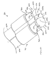
- a surgical device for treating tissue comprising a handle having a proximal end and a distal end; a shaft extending distally beyond the distal end of the handle, the shaft having a proximal end and a distal end; an electrode tip, at least a portion of the electrode tip extending distally beyond the distal end of the shaft, the electrode tip extending distally beyond the distal end of the shaft comprising a spherical end surface portion and a cylindrical side surface portion, the spherical end surface portion located distal to the cylindrical side surface portion and comprising at least a portion of the distal end surface of the surgical device; and a fluid passage directed to provide a fluid towards the cylindrical side portion of the electrode tip.
- a surgical device for treating tissue comprising a handle having a proximal end and a distal end; a shaft extending distally beyond the distal end of the handle, the shaft having a proximal end and a distal end; an electrode tip, at least a portion of the electrode tip extending distally beyond the distal end of the shaft, the electrode tip extending distally beyond the distal end of the shaft comprising a neck portion and an enlarged head portion, the enlarged head portion located distal to the neck portion and comprising at least a portion of a distal end surface of the surgical device; and a fluid passage directed to provide a fluid towards the enlarged head portion of the electrode tip.
- a device for treating tissue comprising a handle having a proximal end and a distal end; a shaft extending distally beyond the distal end of the handle, the shaft having a proximal end and a distal end; an electrode tip, the electrode tip comprising a spherical end surface portion and a cylindrical side surface portion, the spherical end surface portion located distal to the cylindrical side surface portion and comprising at least a portion of the distal end surface of the device; a fluid passage connectable to a fluid source; and a plurality of fluid outlet openings in fluid communication with the fluid passage, the fluid outlet openings positioned to provide a fluid from the fluid source around the cylindrical side surface portion of the electrode tip.
- a device for treating tissue comprising a handle having a proximal end and a distal end; a shaft extending distally beyond the distal end of the handle, the shaft having a proximal end and a distal end; an electrode tip comprising a rounded distal end surface portion configured to blunt dissect tissue and a side surface portion configured to seal tissue from at least one of the flow of bodily fluids and air, the side surface portion having a surface area greater than the surface area of the distal end surface portion; a fluid passage connectable to a fluid source; and at least one fluid outlet opening in fluid communication with the fluid passage, the fluid outlet opening positioned to provide a fluid from the fluid source to the side surface portion of the electrode tip and proximal the distal end surface portion.
- a device for treating tissue comprising a first electrode tip spaced from a second electrode tip, the first and second electrode tips being connectable to different terminals of a radio frequency generator to generate electrical current flow therebetween; at least one fluid passage connectable to a fluid source; at least one fluid outlet opening in fluid communication with the fluid passage, the fluid outlet opening configured to provide a fluid from the fluid source to at least one of a tissue surface and at least one of the first and second electrode tips; and the first and second electrode tips configured to slide over and seal tissue in the presence of a fluid provided from the fluid outlet opening and an electrical current provided from the electrode tips.
- Additional methods for treating tissue may also comprise providing tissue having a tissue surface; providing radio frequency power at a power level; providing an electrically conductive fluid at a fluid flow rate; providing an surgical device configured to simultaneously provide the radio frequency power and the electrically conductive fluid to tissue; providing the electrically conductive fluid to the tissue at the tissue surface; forming a fluid coupling comprising the electrically conductive fluid which couples the tissue and the surgical device; providing the radio frequency power to the tissue at the tissue surface and below the tissue surface into the tissue through the fluid coupling; sealing the tissue against at least one of the flow of bodily fluids and air by at least one of shrinking collagen and coagulating blood in the tissue; and blunt dissecting the tissue.
- methods for treating tissue may also comprise providing tissue having a tissue surface; providing radio frequency power at a power level; providing an electrically conductive fluid at a fluid flow rate; providing an surgical device configured to simultaneously provide the radio frequency power and the electrically conductive fluid to tissue, the surgical device comprising a first electrode tip and a second electrode tip; providing the electrically conductive fluid to the tissue at the tissue surface; forming a fluid coupling comprising the electrically conductive fluid which couples the tissue and the surgical device; providing the radio frequency power to the tissue at the tissue surface and below the tissue surface into the tissue through the fluid coupling; sliding the first electrode tip and the second electrode tip over the tissue surface; and sealing the tissue against at least one of the flow of bodily fluids and air by at least one of shrinking collagen and coagulating blood in the tissue.
- the invention provides devices, systems and methods that preferably improve control of tissue temperature at a tissue treatment site during a medical procedure.
- the invention is particularly useful during surgical procedures upon tissues of the body, where it is desirable to coagulate and shrink tissue, to occlude lumens of blood vessels (e.g. arteries, veins), airways (e.g. bronchi, bronchioles), bile ducts and lymphatic ducts.
- the invention includes electrosurgical procedures, which preferably utilize RF power and electrically conductive fluid, to treat tissue.
- a desired tissue temperature range is achieved by adjusting parameters, such as conductive fluid flow rate, that affect the temperature at the tissue/electrode interface.
- the device achieves a desired tissue temperature by utilizing a desired percentage boiling of the conductive solution at the tissue/electrode interface.
- the invention provides a control device, the device comprising a flow rate controller that receives a signal indicating power applied to the system, and adjusts the flow rate of conductive fluid from a fluid source to an electrosurgical device.
- a control system comprising a flow rate controller, a measurement device that measures power applied to the system, and a pump that provides fluid at a selected flow rate.
- FIG. 1 shows a block diagram of one exemplary embodiment of a system of the invention.
- an electrically conductive fluid 24 is provided from a fluid source 1 through a fluid line 2 to a pump 3, which has an outlet fluid line 4a that is connected as an input fluid line 4b, to electrosurgical device 5.
- the outlet fluid line 4a and the input fluid line 4b are flexible and are made from a polymeric material, such as polyvinylchloride (PVC) or polyolefin (e.g. polypropylene, polyethylene) and the conductive fluid comprises a saline solution.
- PVC polyvinylchloride
- polyolefin e.g. polypropylene, polyethylene
- the saline comprises sterile, and even more preferably, normal saline.
- saline as the fluid 24
- other electrically conductive fluids, as well as non-conductive fluids can be used in accordance with the invention.
- the conductive fluid may comprise hypertonic saline solution, hypotonic saline solution, Ringers solution (a physiologic solution of distilled water containing specified amounts of sodium chloride, calcium chloride, and potassium chloride), lactated Ringer's solution (a crystalloid electrolyte sterile solution of distilled water containing specified amounts of calcium chloride, potassium chloride, sodium chloride, and sodium lactate), Locke-Ringer's solution (a buffered isotonic solution of distilled water containing specified amounts of sodium chloride, potassium chloride, calcium chloride, sodium bicarbonate, magnesium chloride, and dextrose), or any other electrolyte solution.
- the fluid 24 may also comprise an electrically non-conductive fluid.
- the use of a non-conductive fluid is less preferred to that of a conductive fluid as the non-conductive fluid does not conduct electricity.
- the use of a non-conductive fluid still provides certain advantages over the use of a dry electrode including, for example, reduced occurrence of tissue sticking to the electrode of the device 5 and cooling of the electrode and/or tissue. Therefore, it is also within the scope of the invention to include the use of a non-conducting fluid, such as, for example, dionized water.
- energy to heat tissue is provided from energy source, such as an electrical generator 6 which preferably provides RF alternating current energy via a cable 7 to energy source output measurement device, such as a power measurement device 8 that measures the RF alternating current electrical power.
- energy source such as an electrical generator 6 which preferably provides RF alternating current energy via a cable 7 to energy source output measurement device, such as a power measurement device 8 that measures the RF alternating current electrical power.
- the power measurement device 8 does not turn the power off or on, or alter the power in any way.
- a power switch 15 connected to the generator 6 is preferably provided by the generator manufacturer and is used to turn the generator 6 on and off.
- the power switch 15 can comprise any switch to turn the power on and off, and is commonly provided in the form of a footswitch or other easily operated switch, such as a switch 15a mounted on the electrosurgical device 5.
- the power switch 15 or 15a may also function as a manually activated device for increasing or decreasing the rate of energy provided from the surgical device 5.
- internal circuitry and other components of the generator 6 may be used for automatically increasing or decreasing the rate of energy provided from the surgical device 5.
- a cable 9 preferably carries RF energy from the power measurement device 8 to the electrosurgical device 5. Power, or any other energy source output, is preferably measured before it reaches the electrosurgical device 5.
- power P or the rate of energy delivery (e.g. joules/sec)
- I x V current times voltage
- I 2 x R current squared times resistance
- V 2 /R voltage squared divided by the resistance
- the current I may be measured in amperes
- the voltage V may be measured in volts
- the electrical resistance R may be measured in ohms
- the power P may be measured in watts (joules/see).
- the frequency of the RF electrical energy is preferably provided within a frequency band (i.e. a continuous range of frequencies extending between two limiting frequencies) in the range between and including about 9 kHz (kilohertz) to 300 GHz (gigahertz). More preferably, the RF energy is provided within a frequency band in the range between and including about 50 kHz (kilohertz) to 50 MHz (megahertz). Even more preferably, the RF energy is provided within a frequency band in the range between and including about 200 kHz (kilohertz) to 2 MHz (megahertz).
- RF energy is provided within a frequency band in the range between and including about 400 kHz (kilohertz) to 600 kHz (kilohertz). Further, it should also be understood that, for any frequency band identified above, the range of frequencies may be further narrowed in increments of 1 (one) hertz anywhere between the lower and upper limiting frequencies.
- the electrical energy i.e., energy made available by the flow of electric charge, typically through a conductor or by self-propagating waves
- the electrical energy may comprise any frequency of the electromagnetic spectrum (i.e. the entire range of radiation extending in frequency from 10 23 hertz to 0 hertz) and including, but not limited to, gamma rays, x-rays, ultraviolet radiation, visible light, infrared radiation, microwaves, and any combinations thereof.
- heating of the tissue is preferably performed by means of resistance heating.
- increasing the temperature of the tissue as a result of electric current flow through the tissue with the electrical energy being absorbed from the voltage and transformed into thermal energy (i.e. heat) via accelerated movement of ions as a function of the tissue's electrical resistance.
- Heating with electrical energy may also be performed by means of dielectric heating (capacitation).
- dielectric heating capacitation
- Dielectric loss is the electrical energy lost as heat in the polarization process in the presence of the applied electric field.
- an alternating current field the energy is absorbed from the alternating current voltage and converted to heat during the polarization of the molecules.
- energy provided to heat the tissue may comprise surgical devices other than electrosurgical devices, energy sources other than generators, energy forms other than electrical energy and mechanisms other than resistance heating.
- energy provided to heat the tissue may comprise surgical devices other than electrosurgical devices, energy sources other than generators, energy forms other than electrical energy and mechanisms other than resistance heating.
- Such may be provided, for example, to the tissue from a heated device, which heats tissue through direct contact with the energy source (conduction), heats through contact with a flowing fluid (convection), or from a remote heat source (radiation).
- providing energy to the tissue may be provided via mechanical energy which is transformed into thermal energy via accelerated movement of the molecules, such as by mechanical vibration provided, for example, by energy source such as a transducer containing a piezoelectric substance (e.g., a quartz-crystal oscillator) that converts high-frequency electric current into vibrating ultrasonic waves which may be used by, for example, an ultrasonic surgical device.
- energy source such as a transducer containing a piezoelectric substance (e.g., a quartz-crystal oscillator) that converts high-frequency electric current into vibrating ultrasonic waves which may be used by, for example, an ultrasonic surgical device.
- providing energy to the tissue may be provided via radiant energy (i.e. energy which is transmitted by radiation/waves) which is transformed into thermal energy via absorption of the radiant energy by the tissue.
- the radiation/waves comprise electromagnetic radiation/waves which include, but is not limited to, radio waves, microwaves, infrared radiation, visible light radiation, ultraviolet radiation, x-rays and gamma rays. More preferably, such radiant energy comprises energy with a frequency of 3 x 10 11 hertz to 3 x 10 16 hertz (i.e. the infrared, visible, and ultraviolet frequency bands of the electromagnetic spectrum).
- the electromagnetic waves are coherent and the electromagnetic radiation is emitted from energy source such as a laser device.
- a flow rate controller 11 preferably includes a selection switch 12 that can be set to achieve desired levels of percentage fluid boiling (for example, 100%, 98%, 80% boiling).
- the flow rate controller 11 receives an input signal 10 from the power measurement device 8 and calculates an appropriate mathematically predetermined fluid flow rate based on percentage boiling indicated by the selection switch 12.
- a fluid switch 13 is provided so that the fluid system can be primed (e.g. air eliminated) before turning the generator 6 on.
- the output signal 16 of the flow rate controller 11 is preferably sent to the pump 3 motor to regulate the flow rate of conductive fluid, and thereby provide an appropriate fluid flow rate which corresponds to the amount of power being delivered.
- the invention comprises a flow rate controller 11 that is configured and arranged to be connected to a source of RF power (e.g. generator 6), and a source of fluid (e.g. fluid source 1), for example, a source of conductive fluid.
- a source of RF power e.g. generator 6
- a source of fluid e.g. fluid source 1
- the device of the invention receives information about the level of RF power applied to an electrosurgical device 5 , and adjusts the flow rate of the fluid 24 to the electrosurgical device 5, thereby controlling temperature at the tissue treatment site.
- elements of the system are physically included together in one electronic enclosure.
- One such embodiment is shown by enclosure within the outline box 14 of FIG 1 .
- the pump 3, flow rate controller 11, and power measurement device 8 are enclosed within an enclosure, and these elements are connected through electrical connections to allow signal 10 to pass from the power measurement device 8 to the flow rate controller 11, and signal 16 to pass from the flow rate controller 11 to the pump 3.
- Other elements of a system can also be included within one enclosure, depending upon such factors as the desired application of the system, and the requirements of the user.
- the pump 3 can be any suitable pump used in surgical procedures to provide saline or other fluid at a desired flow rate.
- the pump 3 comprises a peristaltic pump.
- a rotary peristaltic pump typically a fluid 24 is conveyed within the confines of a flexible tube (e.g. 4a) by waves of contraction placed externally on the tube which are produced mechanically, typically by rotating rollers which squeeze the flexible tubing against a support intermittently.
- a linear peristaltic pump typically a fluid 24 is conveyed within the confines of a flexible tube by waves of contraction placed externally on the tube which are produced mechanically, typically by a series of compression fingers or pads which squeeze the flexible tubing against a support sequentially.
- Peristaltic pumps are generally preferred for use as the electro-mechanical force mechanism (e.g. rollers driven by electric motor) does not make contact the fluid 24, thus reducing the likelihood of inadvertent contamination.
- pump 3 can be a "syringe pump", with a built-in fluid supply.
- a filled syringe is located on an electro-mechanical force mechanism (e.g. ram driven by electric motor) which acts on the plunger of the syringe to force delivery of the fluid 24 contained therein.
- the syringe pump may comprise a double-acting syringe pump with two syringes such that they can draw saline from a reservoir (e.g. of fluid source 1), either simultaneously or intermittently.
- a double acting syringe pump the pumping mechanism is generally capable of both infusion and withdrawal.
- fluid 24, such as conductive fluid can also be provided from an intravenous (IV) bag full of saline (e.g. of fluid source 1) that flows under the influence (i.e. force) of gravity.
- IV intravenous
- fluid 24 from a fluid source 1 such as an IV bag can be provided through an IV flow controller that may provide a desired flow rate by adjusting the cross sectional area of a flow orifice (e.g. lumen of the connective tubing with the electrosurgical device 5) while sensing the flow rate with a sensor such as an optical drop counter.
- fluid 24 from a fluid source 1 such as an IV bag an be provided through a manually or automatically activated device such as a flow controller, such as a roller clamp, which also adjusts the cross sectional area of a flow orifice and may be adjusted manually by, for example, the user of the device in response to their visual observation (e.g. fluid boiling) at the tissue treatment site or a pump.
- a manually or automatically activated device such as a flow controller, such as a roller clamp, which also adjusts the cross sectional area of a flow orifice and may be adjusted manually by, for example, the user of the device in response to their visual observation (e.g. fluid boiling) at the tissue treatment site or a pump.
- pump 3 may include other types of infusion and withdrawal pumps.
- pump 3 may comprise pumps which may be categorized as piston pumps, rotary vane pumps (e.g. axial impeller, centrifugal impeller), cartridge pumps and diaphragm pumps.
- the pump 3 can be substituted with any type of flow controller, such as a manual roller clamp used in conjunction with an IV bag, or combined with the flow controller to allow the user to control the flow rate of conductive fluid to the device.
- a valve configuration can be substituted for pump 3.
- the fluid source 1 pump 3, generator 6, power measurement device 8 or flow rate controller 11, or any other components of the system not expressly recited above may comprise a portion of the electrosurgical device 5.
- the fluid source 1 may comprise a compartment of the electrosurgical device 5 which contains fluid 24, as indicated at reference character 1a.
- the compartment may be detachably connected to the electrosurgical device 5, such as a canister which may be attached via threaded engagement with the device 5.
- the compartment may be configured to hold a pre-filled cartridge of fluid 24, rather than the fluid directly.
- an energy source such as a direct current (DC) battery used in conjunction with inverter circuitry and a transformer to produce alternating current at a particular frequency
- a portion of the electrosurgical device 5, as indicated at reference character 6a may comprise a portion of the electrosurgical device 5, as indicated at reference character 6a.
- the battery element of the energy source may comprise a rechargeable battery.
- the battery element may be detachably connected to the electrosurgical device 5, such as for recharging.
- the flow rate controller 11 controls the rate of flow from the fluid source 1 .
- the rate of fluid flow from the fluid source 1 is based upon the amount of RF power provided from the generator 6 to the electrosurgical device 5.
- the rate of fluid flow Q and the RF power P indicated by the Y- and X-axes of the schematic graph, respectively.
- the relationship between the rate of fluid flow Q and RF power P may be expressed as a direct, linear relationship.
- the flow rate Q of conductive fluid 24, such as saline interacts with the RF power P and various modes of heat transfer away from the target tissue, as described herein.
- boiling point of saline when the terms "boiling point of saline", "vaporization point of saline”, and variations thereof are used, what is actually referenced for explanation purposes, is the boiling point of the water (i.e. 100°C) in the saline solution given that the difference between the boiling point of normal saline (about 100.16°C) and the boiling point of water is negligible.
- FIG. 2 shows a schematic graph that describes the relationship between the flow rate of saline, RF power to tissue, and regimes of boiling as detailed below.
- the peak tissue temperature can be estimated, and once tissue temperature is estimated, it follows directly whether it is hot enough to boil saline.
- tissue temperature it is undesirable to allow the tissue temperature to reach 320 °C, since tissue will become desiccated.
- the fluid contained in the tissue is typically boiled away, resulting in the undesirable tissue effects described herein. Rather, it is preferred to keep the peak tissue temperature at no more than about 100 °C to inhibit desiccation of the tissue.
- the maximum amount of heat conducted to adjacent tissue without any significant risk of tissue desiccation is 10.5 watts.
- RF power to tissue is represented on the X-axis as P (watts) and flow rate of saline (cc/min) is represented on the Y-axis as Q.
- P watts
- Q flow rate of saline
- Q the flow rate of saline
- This offset is the heat conducted to adjacent tissue. For example, using the calculation above for bipolar forceps, this offset RF power is about 10.5 watts. If the power is increased above this level with no saline flow, the peak tissue temperature can rise well above 100 °C, resulting in tissue desiccation from the boiling off of water in the cells of the tissue.
- Equation (1) The second term [ ⁇ c p Q 1 ⁇ T] in equation (1) is heat used to warm up the flow of saline without boiling the saline, represented as 72 in FIG. 2 , where:
- This equation defines the line shown in FIG. 2 as the line of onset of boiling 76.
- the most significant factor contributing to heat transfer from a wet electrode device can be fractional boiling. The present invention recognizes this fact and exploits it.
- tissue desiccation As indicated previously in the specification, using a fluid to couple energy to tissue inhibits such undesirable effects as sticking, desiccation, smoke production and char formation, and that one key factor is inhibiting tissue desiccation, which occur if the tissue temperature exceeds 100 °C and all the intracellular water boils away, leaving the tissue extremely dry and much less electrically conductive.
- one control strategy or mechanism which can be employed for the electrosurgical device 5 is to adjust the power P and flow rate Q such that the power P used at a corresponding flow rate Q is equal to or less than the power P required to boil 100% of the fluid and does not exceed the power P required to boil 100% of the fluid.
- Another control strategy that can be used for the electrosurgical device 5 is to operate the device 5 in the region T ⁇ 100 °C, but at high enough temperature to shrink tissue containing Type I collagen (e.g., walls ofblood vessels, bronchi, bile ducts, etc.), which shrinks when exposed to about 85 °C for an exposure time of 0.01 seconds, or when exposed to about 65 °C for an exposure time of 15 minutes.
- An exemplary target temperature/time for tissue shrinkage is about 75 °C with an exposure time of about 1 second.
- a determination of the high end of the scale i.e., when the fluid reaches 100 °C
- thermochromic material such as a thermochromic dye (e.g., leuco dye)
- the dye can be formulated to provide a first predetermined color to the fluid at temperatures below a threshold temperature, such as 75 °C, then, upon heating above 75 °C, the dye provides a second color, such as clear, thus turning the fluid clear (i.e. no color or reduction in color).
- This color change may be gradual, incremental, or instant.
- a change in the color of the fluid from a first color to a second color (or lack thereof) provides a visual indication to the user of the electrosurgical device 5 as to when a threshold fluid temperature below boiling has been achieved.
- Thermochromic dyes are available, for example, from Color Change Corporation,1740 Cortland Court, Unit A, Addison, IL 60101.
- the above mechanism i.e., a change in the color of the fluid due to a dye
- An exemplary target temperature/time for tissue necrosis is about 55 °C for an exposure time of about 1 second.
- control strategy which may be employed for the electrosurgical device 5 is to adjust the power P and flow rate Q such that the power P used at a corresponding flow rate Q is equal to or more than the power P required to initiate boiling of the fluid, but still less than the power P required to boil 100% of the fluid.
- this control strategy targets use using the electrosurgical device 5 on or between the lines of the onset of boiling 76 and 100% boiling line 80, and not using the electrosurgical device 5 in the regions of FIG. 2 identified as T ⁇ 100 °C and T >> 100 °C.
- saline flow rate it is desirable to control the saline flow rate so that it is always on a "line of constant % boiling" as, for example, the line of the onset of boiling 76 or the 100% boiling line 80 or any line of constant % boiling located in between (e.g. 50% boiling line 78) as shown in FIG. 2 .
- another control strategy that can be used for the electrosurgical device 5 is to adjust power P and flow rate Q such that the power P used at a corresponding flow rate Q targets a line of constant % boiling.
- boiling of the fluid is not detected, such indicates that the temperature is less than 100 °C as indicated in the area of FIG. 2 , and the flow rate Q must be decreased to initiate boiling.
- the flow rate Q may then decreased until boiling of the fluid is first detected, at which time the line of the onset of boiling 76 is transgressed and the point of transgression on the line 76 is determined. From the determination of a point on the line of the onset of boiling 76 for a particular power P and flow rate Q, and the known slope of the line 76 as outlined above (i.e. 1/ ⁇ c p ⁇ T), it is also possible to determine the heat conducted to adjacent tissue 70.
- boiling of the fluid is detected, such indicates that the temperature is approximately equal to 100°C as indicated in the areas of FIG. 2 , and the flow rate Q must be increased to reduce boiling until boiling stops, at which time the line of the onset of boiling 76 is transgressed and the point of transgression on the line 76 determined.
- the flow rate Q must be increased to reduce boiling until boiling stops, at which time the line of the onset of boiling 76 is transgressed and the point of transgression on the line 76 determined.
- phase change i.e. from liquid to vapor or vice-versa
- a sensor which preferably senses either an absolute change (e.g. existence or non-existence of boiling with binary response such as yes or no) or a change in a physical quantity or intensity and converts the change into a useful input signal for an information-gathering system.
- the phase change associated with the onset of boiling may be detected by a pressure sensor, such as a pressure transducer, located on the electrosurgical device 5.
- the phase change associated with the onset of boiling may be detected by a temperature sensor, such as a thermistor or thermocouple, located on the electrosurgical device 5, such as adjacent to the electrode.
- the phase change associated with the onset of boiling may be detected by a change in the electric properties of the fluid itself For example, a change in the electrical resistance of the fluid may be detected by an ohm meter; a change in the amperage may be measured by an amp meter; as change in the voltage may be detected by a volt meter; and a change in the power may be determined by a power meter.
- Yet another control strategy which may be employed for the electrosurgical device 5 is to eliminate the heat conduction term of equation (1) (i.e. ⁇ T/R). Since the amount of heat conducted away to adjacent tissue can be difficult to precisely predict, as it may vary, for example, by tissue type, it may be preferable, from a control point of view, to assume the worst case situation of zero heat conduction, and provide enough saline so that if necessary, all the RF power could be used to heat up and boil the saline, thus providing that the peak tissue temperature will not go over 100 °C a significant amount. This situation is shown in the schematic graph of FIG. 3 .
- the 98% boiling line, 80% boiling line, etc. can be determined in response to a corresponding input from the selection switch 12.
- the input from the selection switch preferably may comprise any percentage of boiling.
- the percentage of boiling may be selected in single percent increments (i.e. 100%, 99%, 98%, etc.).
- the flow rate controller 11 Upon determination of the line of the onset of boiling 76, the 100% boiling line 80 or any line of constant % boiling there between, it is generally desirable to control the flow rate Q so that it is always on a particular line of constant % boiling for consistent tissue effect. In such a situation, the flow rate controller 11 will adjust the flow rate Q of the fluid 24 to reflect changes in power P provided by the generator 6, as discussed in greater detail below. For such a use the flow rate controller 11 may be set in a line of constant boiling mode, upon which the % boiling is then correspondingly selected.
- the saline flow rate Q it is desirable to control the saline flow rate Q so that it is always on a line of constant % boiling for consistent tissue effect.
- the preferred line of constant % boiling may vary based on the type of electrosurgical device 5. For example, if with use of the device 5, shunting through saline is not an issue, then it can be preferable to operate close to or directly on, but not over the line of the onset of boiling, such as 76a in FIG. 3 . This preferably keeps tissue as hot as possible without causing desiccation. Alternatively, if with use of the device 5 shunting of electrical energy (e.g.
- K 1 ⁇ ⁇ c ⁇ ⁇ ⁇ T + ⁇ ⁇ h v ⁇ Q b / Q l
- the present invention provides a method of controlling boiling of fluid, such as a conductive fluid, at the tissue/electrode interface.
- this provides a method of treating tissue without use of tissue sensors, such as temperature or impedance sensors.
- the invention can control boiling of conductive fluid at the tissue/electrode interface and thereby control tissue temperature without the use of feedback loops.
- ⁇ c p V ⁇ T/ ⁇ t represents the heat required to warm the tissue to the peak temperature (T) 68 and where :
- the inclusion of the heat required to warm the tissue to the peak temperature (T) in the control strategy is graphically represented at 68 in FIG. 4 .
- the effects of the heat required to warm the tissue to the peak temperature (T) 68 should be taken into account before flow rate Q adjustment being undertaken to detect the location of the line of onset of boiling 76.
- the flow rate Q should not be decreased in response to a lack of boiling before at least a quasi-steady state has been achieved as the location of the line of onset of boiling 76 will continue to move during the transitory period.
- FIG. 5 is an exemplary graph of flow rate Q versus % boiling for a situation where the RF power P is 75 watts.
- the percent boiling % is represented on the X-axis
- the saline flow rate Q (cc/min) is represented on the Y-axis. According to this example, at 100 % boiling the most desirable predetermined saline flow rate Q is 2 cc/min.
- flow rate Q versus % boiling at the remaining points of the graft illustrates a non-linear relationship as follows: Table 1 - % Boiling and Flow Rate Q (cc/min) at RF Power P of 75 watts 0% 17.4 10% 9.8 20% 6.8 30% 5.2 40% 4.3 50% 3.6 60% 3.1 70% 2.7 80% 2.4 90% 2.2 100% 2.0
- Typical RF generators used in the field have a power selector switch to 300 watts of power, and on occasion some have been found to be selectable up to 400 watts of power.
- the calculated flow rate Q is 69.7 cc/min and with a corresponding power of 400 watts the calculated flow rate Q is 92.9 cc/min.
- a fluid flow rate Q of about 100 cc/min or less with the present invention is expected to suffice for the vast majority of applications.
- the schematic graph of FIG. 6 shows the general trends of the output curve of a typical general-purpose generator, with the output power changing as load (tissue plus cables) impedance Z changes.
- Load impedance Z (in ohms) is represented on the X-axis
- generator output power P (in watts) is represented on the Y-axis.
- the electrosurgical power (RF) is set to 75 watts in a bipolar mode.
- the power will remain constant as it was set as long as the impedance Z stays between two cut-offs, low and high, of impedance, that is, for example, between 50 ohms and 300 ohms in the illustrated embodiment.
- the power P will decrease, as shown by the low impedance ramp 28a.
- the power P will decrease, as shown by the high impedance ramp 28b.
- the low impedance cut-off low impedance rump 28a
- FIG. 7 shows the general trend of how tissue impedance generally changes with time for saline-enhanced electrosurgery.
- the temperature coefficient of the tissue and saline in the cells is such that the tissue impedance decreases until a steady-state temperature is reached upon which time the impedance remains constant.
- the load impedance Z decreases, potentially approaching the impedance Z cut-off of 50 ohms. If tissue is sufficiently heated, such that the low impedance cut-off is passed, the power P decreases along the lines of the low impedance ramp 28a of FIG. 6 .
- the control device receives a signal indicating the drop in actual power delivered to the tissue and adjusts the flow rate Q of saline to maintain the tissue/electrode interface at a desired temperature.
- the drop in actual power P delivered is sensed by the power measurement device 8 (shown in FIG. 1 ), and the flow rate Q of saline is decreased by the flow rate controller 11 (also shown in FIG. 1 ).
- this reduction in saline flow rate Q allows the tissue temperature to stay as hot as possible without desiccation. If the control device was not in operation and the flow rate Q allowed to remain higher, the tissue would be over-cooled at the lower power input. This would result in decreasing the temperature of the tissue at the treatment site.
- the flow rate controller 11 of FIG. 1 can be a simple "hard-wired" analog or digital device that requires no programing by the user or the manufacturer.
- the flow rate controller 11 can alternatively include a processor, with or without a storage medium, in which the determination procedure is performed by software, hardware, or a combination thereof.
- the flow rate controller 11 can include semi-programmable hardware configured, for example, using a hardware descriptive language, such as Verilog.
- the flow rate controller 11 of FIG. 1 is a computer, microprocessor-driven controller with software embedded.
- the flow rate controller 11 can include additional features, such as a delay mechanism, such as a timer, to automatically keep the saline flow on for several seconds after the RF is turned off to provide a post-coagulation cooling of the tissue or "quench,” which can increase the strength of the tissue seal. Also, in another embodiment, the flow rate controller 11 can include a delay mechanism, such as a timer, to automatically turn on the saline flow several seconds before the RF is turned on to inhibit the possibility of undesirable effects as sticking, desiccation, smoke production and char formation.
- a delay mechanism such as a timer
- the flow rate controller 11 can include a low level flow standby mechanism, such as a valve, which continues the saline flow at a standby flow level (which prevents the flow rate from going to zero when the RF power is turned off) below the surgical flow level ordinarily encountered during use of the electrosurgical device 5.
- a low level flow standby mechanism such as a valve, which continues the saline flow at a standby flow level (which prevents the flow rate from going to zero when the RF power is turned off) below the surgical flow level ordinarily encountered during use of the electrosurgical device 5.
- FIG. 9 An exemplary electrosurgical device of the present invention which may be used in conjunction with the system of the present invention is shown at reference character 5a in FIG. 9 , and more particularly in FIGS. 9-13 . While various electrosurgical devices of the present invention are described with reference to use with the remainder of the system of the invention, it should be understood that the description of the combination is for purposes of illustrating the remainder of the system of the invention only. Consequently, it should be understood that the electrosurgical devices of the present invention can be used alone, or in conjuction with the remainder of the system of the invention, or that a wide variety of electrosurgical devices can be used in connection with the remainder of the system of the invention
- the electrosurgical devices disclosed herein are preferably further configured for both open and laparoscopic surgery. For laparoscopic surgery, the devices are preferably configured to fit through either a 5 mm or 12 mm trocar cannula.
- electrosurgical device 5a may be used in conjunction with a cannula as illustrated at reference character 19, during laparoscopic surgery such as, for example, a laparoscopic cholecystectomy.
- Cannula 19 comprises a proximal portion 19a separated from a distal portion 19b by an elongated rigid shaft portion 19c.
- Proximal portion 19a of cannula 19 preferably comprises a head portion 19d connected to rigid shaft portion 19c, preferably by threaded engagement.
- cannula 19 has a working channel 19e which extends through head portion 19d and shaft portion 19c from proximal portion 19a to distal portion 19b of cannula 19.
- electrosurgical device 5a is configured to enter the proximal end of working channel 19e, move along the channel 19e distally, and then be extended from the distal end of the working channel 19e.
- electrosurgical device 5a is configured to enter the distal end of working channel 19e, move along the channel 19e proximally, and then be removed from the proximal end of working channel 19e.
- electrosurgical device 5a comprises a monopolar electrosurgical device.
- electrosurgical device 5a preferably includes a rigid, self-supporting, hollow shaft 17, a proximal handle comprising mating handle portions 20a, 20b and a tip portion as shown by circle 45.
- Handle 20a, 20b is preferably made of a sterilizable, rigid, non-conductive material, such as a polymer (e.g. polycarbonate).
- tip portion 45 includes a contact element preferably comprising an electrode 25 which, as shown, comprises a solid ball having a smooth, uninterrupted surface. Also as shown in FIGS.
- tip portion 45 also comprises a sleeve 82 having a uniform diameter along its longitudinal length, a spring 88 and a distal portion of shaft 17.
- the longitudinal axis 31 of the tip portion 45 may be configured at an angle A relative to the longitudinal axis 29 of the proximal remainder of shaft 17.
- the longitudinal axis 31 of the tip portion 45 is configured at an angle A of about 5 degrees to 90 degrees relative to the longitudinal axis 29 of the proximal remainder of shaft 17. More preferably, the longitudinal axis 31 of tip portion 45 is configured at an angle A of about 8 degrees to 45 degrees relative to the longitudinal axis of 29 of the proximal remainder of shaft 17.
- electrode 25 generally has a spherical shape with a corresponding spherical surface, a portion 42 of which is exposed to tissue 32 (less than 180 degrees and more specifically about 100-120 degrees) at the distal end of device 5a.
- the sphere may have any suitable diameter.
- the sphere preferably has a diameter in the range between and including about 1 mm to about 7 mm.
- tissue treatment can be adversely effected (particularly tissue treatment time) due to an electrode surface that is respectively either to large or to small.
- the sphere has a diameter in the range between and including about 2.5 mm to about 3.5 mm. Even more preferably; the sphere has a diameter of about 3 mm.
- a distal end surface of electrosurgical device 5a always provides a blunt, rounded surface which is non-pointed and non-sharp as shown by electrode 25.
- electrode 25, is preferably located in a cavity 81 of a cylindrical sleeve 82 providing a receptacle for electrode 25.
- sleeve 82 guides movement of the electrode 25.
- sleeve 82 also functions as a housing for retaining the electrode 25.
- electrode 25 is retained within the cavity 81 while another portion 43 extends distally through the fluid outlet opening provided by circular fluid exit hole 26.
- sleeve 82 is connected, preferably via welding with silver solder, to the distil end 53 of shaft 17.
- electrode 25, sleeve 82 and shaft 17 preferably comprise, and more preferably at least essentially consists of, an electrically conductive metal, which is also preferably non-corrosive, and more particularly stainless steel. Other metals include copper, titanium, gold, silver and platinum.
- shaft 17 preferably comprises thick walled stainless steel hypo-tubing.
- cavity 81 the internal diameter of cavity 81 surrounding the electrode 25, is preferably slightly larger than the diameter of the sphere, typically by about 0.25 mm. This permits the sphere to freely rotate within the cavity 81. Consequently, cavity 81 of sleeve 82 also preferably has a diameter in the range of about 1 mm to about 7 mm.
- the fluid exit hole 26, which ultimately provides a fluid outlet opening, of cavity 81 at its distal end 83 comprises a distal pinched region 86 which is reduced to a size smaller than the diameter of the electrode 25, to inhibit escape of the electrode 25 from the sleeve 82. More preferably, the fluid exit hole 26 comprises a diameter smaller than the diameter of the electrode 25.
- the fluid exit hole 26 preferably has a diameter smaller than the diameter of the electrode 25, which can be accomplished by at least one crimp 84 located at the distal end 83 of the sleeve 82 which is directed towards the interior of the sleeve 82 and distal to the portion 44 of the electrode 25 confined in cavity 81.
- the crimp 84 may comprise a single continuous circular rim pattern.
- the contact element portion extending distally through the fluid outlet opening (i.e. electrode portion 43) provided by fluid exit hole 26 has a complementary shape to the fluid outlet opening provided by fluid exit hole 26, here both circular.
- the crimp 84 may also comprise a discontinuous circular rim pattern where the crimp 84 is interrupted by at least one rectangular hole slot 85 formed at the distal end 83 of the sleeve 82.
- the fluid outlet opening located at the distal end of the device 5a may comprise a first portion (e.g. the circular fluid exit hole portion 26) and a second portion (e.g. the slot fluid exit hole portion 85).
- crimp 84 comprises at least four crimp sections forming a circular rim pattern separated by four discrete slots 85 radially located there between at 90 degrees relative to one another and equally positioned around the fluid outlet opening first portion.
- slots 85 are preferably used to provide a fluid outlet opening or exit adjacent the electrode 25, when the electrode 25 is fully seated (as discussed below) and/or when the electrode 25 is not in use (i.e. not electrically charged) to keep surface portion 42 of the electrode surface of electrode 25 wet.
- slots 85 have a width in the range between and including about 0.1 mm to 1 mm, and more preferably have a width in the range between and including about 0.2 mm to 0.3 mm.
- slots 85 preferably have a length in the range between and including about 0.1 mm to 1 mm, and more preferably have a length in the range between and including about 0.4 mm to 0.6 mm.
- the contact element portion extending distally through the fluid outlet opening extends distally through the fluid outlet opening first portion (e.g. the circular fluid exit hole portion 26) and does not extend distally through the fluid outlet opening second portion (e.g. the slot fluid exit hole portion 85). In this manner an edge 91 of the slot 85 remains exposed to tissue 32 to provide a tissue separating edge as discussed below.
- fluid exit hole 26 may comprise an oval shape while electrode 25, comprises a different shape, such as a round shape.
- At least one edge 91 of slot 85 may provide a tissue separating edge adjacent a blunt surface (e.g. surface portion 42 of the electrode 25) which may be used for blunt dissection when the electrosurgical device 5a is manipulated, particularly by rotating (e.g, twirling), abrading or impacting.
- a blunt surface e.g. surface portion 42 of the electrode 25
- the edge may comprise a sharp edge with a sharp angle which has not been rounded by, for example, a fillet.
- the portion of the sleeve 82 proximal to the electrode 25, also has a proximal pinched region 87 which retains the electrode 25 in the cavity 81 of the sleeve 82 and inhibits escape of the electrode 25 from the cavity 81 of the sleeve 82, such as a diameter smaller than the diameter of the electrode 25.
- distal pinched region 86 and proximal pinched region 87 may be used solely to support the electrode 25, in its position of use, the electrode may be further supported by a compression spring 88 as shown in FIG. 11 .
- the use of spring 88 is preferred to provide a variable length support within the working length of the spring 88 for overcoming manufacturing tolerances (e.g. length) between the fixed supports (i.e. pinched regions 86 and 87) of the sleeve 82.
- sleeve 82 also comprises a lumen 89 as shown in FIG. 11 (i.e.
- the cavity of an elongated hollow structure such as a tube or tube like structure; typically cylindrical
- a guide tube for spring 88 which, in addition to providing a direct passage for fluid, provides a guide tube for spring 88.
- the surface portion 60 of electrode 25, which contacts the spring 88 may comprise a flat surface rather than a curvilinear surface to better seat the spring against the electrode 25.
- spring 88 provides a multitude of functions and advantages.
- the configuration of the distal pinched region 86, proximal pinched region 87 and spring 88 offers the ability to move the electrode 25, distally and proximally within sleeve 82.
- spring 88 is located proximal to the electrode 25 between a first load bearing surface comprising the electrode surface 60 and a second load bearing surface comprising the distal end 53 of shaft 17.
- spring 88 can be configured to provide a decompression force to seat the electrode 25 against the distal pinched region 86, in this case the perimeter edge 92 of crimp 84, prior to use of the electrosurgical device 5a.
- the contact element comprising electrode 25 is retractable into the cavity 81 of the housing provided by sleeve 82 upon the application of a proximally directed force against surface 42 of the portion 43 of the electrode 25 extending distally beyond the distal opening 26 located at the distal end 83 of the housing and spring 88 functions as a retraction biasing member.
- the electrosurgical device 5a can be provided with a damper mechanism which dampens the force of the electrode 25 on tissue 32 being treated.
- an electrode 25 which can be positioned as outlined above can comprise a fluid flow rate adjustment mechanism which incrementally increases the area of the fluid exit hole 26 and the corresponding fluid flow rate in response to the incremental proximal retraction of the electrode 25.
- the electrode 25 functions as a valve in regulating flow of the fluid 24 through fluid exit hole 26.
- spring 88 may be used in conjunction with the distal pinched region 86 (e.g. crimp 84 comprising a single continuous circular pattern) to provide a fluid seal between the electrode 25 and the distal pinched region 86 which stops fluid flow from the electrosurgical device 5a.
- the electrosurgical 5a device may be used to provide both a wet electrode and dry electrode (i.e. when the fluid flow is on and off, respectively) with the energy and fluid provided sequentially in addition to simultaneously.
- the incorporation of a dry electrode function into the device of the currant invention may be desirable to provide a mechanism, for electrosurgical cutting.
- an electrode 25 which can be positioned as outlined above can comprise a declogging mechanism which retracts to provide access for unclogging fluid exit holes, such as fluid exit holes 26 and 85, which may become flow restricted as a result of loose debris (e.g. tissue, blood) becoming lodged therein.
- a biasing force such as from a handheld cleaning device (e.g.
- an electrode 25 which can be positioned as outlined, provides a method for declogging a fluid exit hole by increasing the cross-sectional area of the fluid exit hole to provide access thereto.
- the spring 88 comprises an electrical conductor, particularly when the electrode 25, is retracted to a non-contact position (i.e. not in contact) with the sleeve 82.
- proximal pinched region 87 may comprise one or more crimps similar to distal pinched region 86, such that electrode 25 is retained in sleeve 82 both distally and proximally by crimps.
- sleeve 82 may be disposed within shaft 17 rather than being connected to the distal end 53 of shaft 17.
- sleeve 82 may be formed unitarily (i.e. as a single piece or unit) with shaft 17 as a unitary piece.
- the electrode 25 is retained in the sleeve 82 such that a portion 43 of the electrode 25 extends distally beyond distal end 83 of the sleeve 82.
- the surface 42 of this exposed portion 43 of the electrode 25 is blunt and does not comprise any sharp corners.
- the portion 43 of the electrode 25 which extends distally beyond the distal end 83 of the sleeve 82 is controlled by the shape of the fluid exit hole 26 in sleeve 82 in relation to the shape of the electrode 25. In other words, the portion 43 of the electrode 25 which extends distally beyond the distal end 83 of the sleeve 82 is controlled by the contact of the electrode surface with the edge 92.
- an electrical insulator 90 preferably surrounds shaft 17 and sleeve 82 along substantially its entire exposed length (e.g. the portion outside the confines of the handle 20), terminating a short distance (e.g, at the proximal onset of the crimp 84 or less than about 3 mm) from distal end 83 of the sleeve 82.
- Insulator 90 preferably comprises a shrink wrap polymer tubing.
- a input fluid line 4b and a power source, preferably comprising generator 6 preferably providing RF power via cable 9, are preferably fluidly and electrically coupled, respectively, to the tip portion 45 of the electrosurgical device 5a.
- device 5a comprises a monopolar device.
- a first electrode often referred to as the active electrode, comprises an electrode of the electrosurgical device 5a (e.g. electrode 25) while a second electrode, often referred to as the indifferent or return electrode, comprises a ground pad dispersive electrode located on the patient, typically on the back or other suitable anatomical location.
- both electrodes are electrically coupled to the generator 6 to form an electrical circuit.
- the active electrode is coupled to the generator 6 via a wire conductor from insulated wire cable 9 to the outer surface 18 of the shaft 17 within the confines of the handle 20a, 20b, typically through a switch 15a.
- the shaft 17 may be made of an electrical non-conducting material except for a portion at its distal end 53 that comes in contact with sleeve 82. This portion of shaft 17 that contacts the sleeve 82 should be electrically conducting. In this embodiment, the wire conductor from insulated wire cable 9 extends to this electrically conducting portion of shaft 17. In still other embodiments, the shaft 17 may completely comprise a non-conducting material as where the wire conductor from insulated wire cable 9 extends directly to the sleeve 82.
- fluid 24 from the fluid source 1 for use with electrosurgical device 5a preferably is communicated from fluid source 1 through a flexible, polyvinylchloride (PVC) outlet fluid line 4a to a flexible, polyvinylchloride (PVC) inlet fluid line 4b connected to the electrosurgical device 5a.
- the outlet fluid line 4a and the inlet fluid line 4b are preferably connected via a male and female mechanical fastener configuration, preferably comprising a Luer-Lok® connection from Becton, Dickinson and Company.
- the lumen of the inlet line is then preferably interference fit over the outside diameter of the shaft 17 to provide a press fit seal there between. Additionally an adhesive may be disposed there between to strengthen the seal.
- Fluid 24 is then communicated down the lumen 23 of the shaft 17 through the lumen 89 and cavity 81 of the sleeve 82 where it is expelled from around and on the exposed surface 42 of the electrode 25. This provides a wet electrode for performing electrosurgery.
- a fluid coupling 30 preferably comprising a discrete, localized web and more preferably comprising a triangular shaped web or bead portion providing a film of fluid 24 is provided between the surface 22 of the tissue 32 and electrode 25.
- a fluid coupling 30 preferably comprising a discrete, localized web and more preferably comprising a triangular shaped web or bead portion providing a film of fluid 24 is provided between the surface 22 of the tissue 32 and electrode 25.
- the electrode 25 typically slides across the surface 22 of the tissue 32, but also may rotate as the electrode 25 moves across the surface 22 of the tissue 32.
- the user of the electrosurgical device 5a slides the electrode across the surface 22 of the tissue 32 back and forth with a painting motion while using the fluid 24 as, among other things, a lubricating coating.
- the thickness of the fluid 24 between the distal end surface of the electrode 25 and the surface 22 of the tissue 32 at the outer edge of the coupling 30 is in the range between and including about 0.05 mm to 1.5 mm.
- the fluid 24 between the distal end surface of the electrode 25 and the surface 22 of the tissue 32 at the outer edge of the coupling 30 is in the range between and including about 0.1 mm to 0.3 mm. Also preferably, in certain embodiments, the distal end tip of the electrode 25 contacts the surface 22 of tissue 32 without any fluid 24 in between.
- electrical insulator 90 preferably terminates proximally to the sleeve 82 where sleeve 82 is connected to the distal end 53 of shaft 17.
- the electrical insulator 90 preferably terminate proximally to proximal pinched region 87.
- a cylindrical surface 40 of a cylindrical portion 39 of the sleeve 82 and a broadening surface portion 47 of broadening portion 54, here both conical, of the sleeve 82 also function as electrode surfaces for treating tissue.
- the electrode exposed to tissue 32 now comprises a cylindrical surface portion 40 and a broadening surface portion 47 in addition to the spherical surface portion 42 and the narrowing surface portion 41, with the cylindrical surface portion 40 substantially increasing the surface area of the electrode.
- the electrode 25 now also comprises surfaces which are parallel and perpendicular to the longitudinal axis 31 of the tip portion 45, and more particularly sleeve 82, of the electrosurgical device 5b.
- front end use e.g. surfaces 41 and 42
- sideways use e.g. surface 40 and 47
- oblique use e.g. surfaces 40, 41 and 42
- the tip portion 45 now comprises a first tissue treating surface (e.g. distal end spherical surface 42) and a second tissue treating surface (e.g. side surface 40).
- first tissue treating surface e.g. distal end spherical surface 42
- second tissue treating surface e.g. side surface 40
- first tissue treating surface is configured for blunt dissection while the second tissue treating surface is configured for coagulation.
- tip portion 45 also comprises a third tissue treating surface (e.g. surface 41) located between the first tissue treating surface (e.g. surface 42) and a second tissue treating surface (e.g. surface 40).
- tip portion 45 also comprises a fourth tissue treating surface (e.g. surface 47) located proximal and adjacent to surface 40.
- fluid exit holes 93, 94 may be located in the cylindrical side portion 39 of the sleeve 82, either proximal or adjacent to the electrode 25, and either in addition to or as an alternative to fluid exit holes 26, 85.
- At least one fluid exit hole 93 is preferably formed in the cylindrical longitudinal side surface 40 and though the wall of side portion 39 of the sleeve 82 adjacent to electrode 25 when electrode 25 is fully seated. Furthermore, preferably at least one fluid exit hole 94 is formed in the cylindrical side portion 39 of the sleeve 82 proximal to electrode 25 when electrode 25 is fully seated.
- holes 93, 94 each comprise more than one hole which are equally spaced radially in a circular pattern around the longitudinal axis 31 of the tip portion 45, and more particularly sleeve 82. More preferably, holes 93, 94 each comprise four discrete holes equally spaced 90 degrees around the cylindrical side portion 39 of the sleeve 82. Preferably holes 93, 94 have a diameter in the range between and including about 0.1 mm to 1.0 mm, and more preferably have a length in the range between and including about 0.2 mm to 0.6 mm.
- Electrode 25 which can be positioned as outlined above can comprise not only a valve for regulating fluid flow from the fluid exit holes, such as fluid exit hole 26, but also comprise a valve which while opening one fluid flow exit simultaneously closes another fluid flow exit. For example, as electrode 25 retracts proximally, fluid exit hole 26 is opened while fluid exit hole 93 is closed. Stated another way, an electrode 25 which can be positioned as outlined above can provide a mechanism for altering the size and/or location of the fluid exit holes during use of the electrosurgical device 5b which may be necessary, for example, to direct fluid to a particular tissue location or balance fluid flow among the fluid exit outlets.
- surfaces 40, 41 and 47 of the sleeve 82, and surface 42 of electrode 25 are all active electrode surfaces and can provide electrical energy to tissue 32. Portions of this combined electrode surface can be wet by fluid flow from holes 26, 94 or 93, as well as from the hole slots 85 in the crimp 84 adjacent the electrode 25.
- the holes 94, 93 in the cylindrical sleeve 82 of the overall electrode surface are intended to assure that fluid 24 is provided to the smooth, less rough, traumatic sides of the electrode that are used to produce tissue coagulation and hemostasis (e.g. surfaces 40 and 47) rather than blunt dissection (e.g. surfaces 41 and 42).
- the most distal portion of the device may have a more rough, but also wetted, electrode surface that can blunt dissect as well as coagulate tissue.
- the electrode configuration shown in FIGS. 14 and 15 is particularly useful to a surgeon performing a liver resection.
- the distal tip of tip portion 45 is painted back and forth along the line, resulting in coagulation of the liver parenchyma.
- the electrode is used to blunt dissect into the coagulated parenchyma, with the edge 91 of the slots 85 around the crimp 84 providing roughness elements that aid in disrupting the tissue 32 and enabling the parting of the tissue 32.
- the device 5b can be used deeply in a crevice 97 of tissue 32 to blunt dissect the tissue 32 and coagulate it at the same time.
- Blunt dissection is preferred over sharp dissection, such as with a blade or scissors, since blunt dissection is less likely to tear or damage the larger blood vessels or other vessels.
- larger vessels can be safely clipped, tied with suture or sealed with some other device. If the larger vessels are not thus first "skeletonized" without being damaged by blunt dissection, they may bleed profusely and require much more time to stop the bleeding.
- the device can also be used to coagulate first without simultaneous blunt dissection, and then blunt dissect in a separate step.
- This technique can also be used on other parenchymal organs such as the pancreas, the kidney, and the lung. In addition, it may also be useful on muscle tissue and subcutaneous fat Its use can also extend to benign tumors, cysts or other tissue masses found in the urological or gynecological areas. It would also enable the removal of highly vascularized tumors such as hemangiomas.
- the zone 99 identifies the part of the electrode that has the ability to blunt dissect and coagulate, and the zone 98 identifies the part that is intended primarily for coagulation and hemostasis.
- the line 100 indicates the depth of the zone of tissue that is coagulated, typically from 3 mm to 5 mm deep.
- FIG. 17 shows a plot of electrical impedance Z versus time t .
- the impedance spikes 101 shown in FIG. 17 occur at a frequency of about 1 cycle per second and with an amplitude that is on the same order as the baseline impedance. This frequency is shown in FIG. 17 as the interval 102 between successive impedance spikes. Impedance is directly measurable by dividing the voltage by the current as previously described. The use of electrical impedance to detect the onset of tissue dessication when impedance rises dramatically as a result of being heated to the point of smoking and charring, but not to detect the presence of boiling, is described above.
- the impedance Z may change from a level of about 100 ohms with no boiling, to a level of about 400 ohms or more with a large fraction of the conductive fluid boiling.
- the percentages of boiling shown are exemplary as are the levels of impedance.
- FIG. 18 Shown in FIG. 18 is the qualitative nature of the boiling as the % boiling increases, indicated by the small figures for each of five exemplary "regimes" of boiling.
- a portion of the tip of the tip portion 45 of the device 5a is shown in close proximity to tissue 32 .
- As the percentage of boiling increases at regime 106 there are a larger number of small bubbles 37.
- the bubbles 37 become much larger.
- drops 36 of saline are instantly boiled upon contacting the hot surface 22 of the tissue 32 and arcing occurs from the metal to the tissue 32.
- fluid outlet openings are provided by substantially linear through holes 93, 94 which provide conductive fluid 24 to the treatment site.
- fluid outlet openings in the sleeve 82 may be provided by holes in the form of tortuous and interconnected pathways 59, which are formed in a material pervious to the passage of fluid 24, therethrough, such as a porous material.
- the discrete, linear through holes 93, 94 may be either supplemented with or replaced by a plurality of tortuous, interconnected pathways 59 formed in the porous material which, among other things, provides porous surfaces 40, 41 and 47 to more evenly distribute fluid flow and provide the conductive fluid 24 to tissue 32 at the treatment site.
- all or a portion of the sleeve 82 may comprise a material pervious to the passage of fluid 24 therethrough as disclosed herein.
- the contact element, here electrode 25 may also comprise a material pervious to the passage of fluid 24, therethrough, such as a porous material (e.g. metal, polymer or ceramic) to provide the tortuous pathways 59.
- a porous material e.g. metal, polymer or ceramic
- the porous structure of the electrode 25 allows fluid 24 to not only pass around electrode 25 on the outer porous surface 42 to be expelled, but also allows fluid 24 to pass through the electrode 25, to be expelled.
- all or a portion of the electrodes or any particular electrodes for treating tissue 32 may comprise a material pervious to the passage of fluid 24 therethrough as disclosed herein.
- the porous material further comprises porous metal.
- Porous sintered metal is available in many materials (such as, for example, 316L stainless steel, titanium, Ni-Chrome) and shapes (such as cylinders, discs, plugs) from companies such as Porvair, located in Henderson, NC.
- Porous metal components can be formed by a sintered metal powder process or by injection molding a two-part combination of metal and a material that can be burned off to form pores that connect (open cell) to each other.
- sintering typically solid particles of material are placed in a mold under heat and pressure such that the outer surface of the particles soften and bond to one another with the pores comprising the interstices between the particles.
- porosity is formed by burning off material, it is not the interstice between the particles which provides the porosity as with sintering, but rather a partial evisceration of the material generally provided by the removal of a component with a lower melt temperature than the burn off temperature.
- the electrode provided by contact element and/or sleeve preferably comprises an electrically conductive material such as metal
- a non-electrically conductive porous contact element and/or sleeve such as porous polymers and ceramics
- the porous polymers and ceramics are generally non-conductive, they may also be used to conduct the RF energy through the porous polymer and ceramic thickness and porous surface to the tissue to be treated by virtue of conductive fluid 24 contained within the plurality of interconnected tortuous pathways 59.
- the tortuous passages in the porous materials have a pore size (cross-sectional dimension) in the range between and including about 2.5 micrometers (0.0025 mm) to 500 micrometers (0.5 mm) and more preferably has pore size in the range between and including about 10 micrometers (0.01 mm) to 120 micrometers (0.12 mm). Even more preferably, the porous material has a pore size in the range between and including about 20 micrometers (0.02 mm) to 80 micrometers (0.08 mm).
- the porous materials may provide other advantages.
- the tissue 32 is less apt to stick to the surfaces 40, 41, 42 and 47 of the electrode as compared to the situation where the surfaces 40, 41, 42 and 47 are not porous.
- heated and/or electrified fluid 24 can now be provided more uniformly to surfaces 40, 41, 42 and 47, which may result in a wider tissue treatment region as compared to when the surfaces are not porous.
- the porous material provides for the wicking (i.e. drawing in of fluid by capillary action or capillarity) of the fluid 24 into the pores of the porous material.
- the porous material is hydrophilic.
- the porous material may be hydrophilic with or without post treating (e.g. plasma surface treatment such as hypercleaning, etching or micro-roughening, plasma surface modification of the molecular structure, surface chemical activation or crosslinking), or made hydrophilic by a coating provided thereto, such as a surfactant.
- fluid coupling 30 of fluid 24 be present in between the metal electrode surfaces (e.g. 40, 41, 42) and tissue 32 at all locations of tissue treatment and there may be points of direct tissue contact by the electrode surfaces without any fluid coupling 30 therebetween.
- the convective cooling of the metal electrode by flowing saline is often sufficient to keep the metal electrode and tissue contacting the metal electrode at or below a temperature of 100 °C.
- heat may be also first dissipated from the tissue 32 to the electrodes by conduction, then dissipated from the electrodes to the fluid 24 by convection.
- the relationship between the material for electrodes particularly their surfaces (e.g. 40, 41, 42, 47 ), and fluid 24 throughout the various embodiments should be such that the fluid 24 wets the surface of the electrodes to form a continuous thin film coating thereon (for example, see FIG. 19A) and does not form isolated rivulets or circular beads (e.g. with a contact angle, ⁇ greater than 90 degrees) which freely run off the surface of the electrode.
- Contact angle, 0, is a quantitative measure of the wetting of a solid by a liquid. It is defined geometrically as the angle formed by a liquid at the three phase boundary where a liquid, gas and solid intersect.
- contact angle ⁇ may be defined by the preceding equation
- contact angle ⁇ is determined by a various models to an approximation.
- publication entitled " Surface Energy Calculations” (dated September 13, 2001 ) from First Ten Angstroms (465 Dinwiddie Street, Portsmouth, Virginia 23704)
- the five predominate models and their synonyms are: (1) Zisman critical wetting tension; (2) Girifalco, Good, Fowkes, Young combining rule; (3) Owens, Wendt geometric mean; (4) Wu harmonic mean; and (5) Lewis acid/base theory.
- any one of the five predominate models above which calculates a contact angle ⁇ within a particular range of contact angles ⁇ or the contact angle 9 required of a particular embodiment of the invention should be considered as fulfilling the requirements of the embodiment, even if the remaining four models calculate a contact angle ⁇ which does not fulfill the requirements of the embodiment.
- Bond number N BO 1
- the droplet diameter is equal to about .273 cm or about 2.7 mm, which is in the same order of magnitude as the preferred size of the electrode.
- Bond number N BO for a droplet of fluid 24 on a surface of the electrode 25 is preferably less than 1.
- FIGS. 20-24 Another tip portion of an exemplary electrosurgical device 5c of the present invention which may be used in conjunction with the system of the present invention is shown at reference character 45 in FIGS 20-24 .
- the separate sleeve 82 of embodiments 5a and 5b has been eliminated from tip portion 45 of device 5c. Consequently, the contact element, still preferably comprising an electrode 25, is assembled directly with the shaft 17.
- Electrode 25 is preferably assembled (e.g. mechanically connected via press fit, mechanical connector, threaded, welded, adhesively bonded) adjacent the distal end 53 of shaft 17.
- the electrode 25 preferably is detachably assembled to the shaft 17 such that it may be removed from the shaft 17, preferably manually by human hand, so that the shaft 17 may be used with multiple different contact elements/electrodes, or the shaft 17 may be reuseable and used with disposable contact elements/electrodes.
- electrode 25 preferably comprises an enlarged head portion comprising a spherical portion 43 and a corresponding spherical surface portion 42 located at the distal end of the device 5c which provided a smooth, blunt contour outer surface. More specifically, as shown, the spherical portion 43 and spherical surface portion 42 further provide a domed, hemisphere (i.e. less than a full sphere) and hemispherical surface portion comprising preferably about 180 degrees.
- the enlarged head portion of electrode 25 preferably also comprises a cylindrical portion 39 and a corresponding cylindrical surface portion 40 located proximal and adjacent to the spherical portion 43 and spherical surface portion 42, respectively.
- electrode 25 preferably comprises a connector portion, preferably comprising a shank 46, which connects the remainder of the electrode 25 to the shaft 17.
- the connector portion of the electrode 25 is preferably configured to form a connection with a mating connector portion of the shaft 17.
- the shank portion 46 is configured to extend into cavity 50 of shaft 17 which comprises a cylindrical receptacle and provides the mating connector portion for shank 46.
- surface 48 of the shank portion 46 is configured to mate against and form an interference fit with surface 52 of cavity 50 to provide the connection.
- shank portion 46 is preferably cylindrical and located proximal and adjacent to a neck portion 56.
- neck portion 56 also comprises a cylindrical portion 57 (having a corresponding cylindrical surface portion 58) located proximal and adjacent to a broadening portion 54 (having a corresponding broadening surface portion 47 ).
- broadening portion 54 and corresponding broadening surface portion 47 are both spherical, and more specifically comprise a domed, hemisphere and hemispherical surface portion comprising preferably about 180 degrees, located proximal and adjacent to the cylindrical portion 39 and cylindrical surface portion 40.
- the cylindrical portion 57 of neck portion 56 preferably has a cross-sectional dimension, here diameter, greater than the cross-sectional dimension, here also diameter, of the shank 46.
- the proximal end of the neck portion 56 may be located adjacent and in contact with the distal end 53 of shaft 17 .
- electrode 25 comprises at least one recess 64 which provides an elongated fluid flow channel for the distribution of fluid 24 .
- the use of device 5c , and in particular recesses 64, for the distribution of fluid 24 is generally preferred to the fluid exit holes 93, 94 of device 5b in particularly deep tissue crevices 97 where tissue 32 can occlude fluid flow from the fluid exit holes located in the cylindrical portion 39 of the electrode 25.
- electrode 25 preferably comprises a plurality of longitudinally directed recesses 64 and, more specifically, four recesses 64 equally spaced 90 degrees around the shank 46 and/or neck portion 56, both proximal of cylindrical portion 39.
- the recess 64 may comprise a first side wall 64a, a second opposing side wall 64b, and a bottom wall 64c.
- fluid 24 from recess 64 may still be expelled from the electrosurgical device 5c after flowing longitudinally in the channel 64 to a remote location where the channel 64 is unoccluded and uninhibited to fluid flow exiting therefrom.
- the recess 64 may be occluded by tissue 32 completely along its longitudinal length, thus completely inhibiting fluid flow from exiting through opening 55.
- at least a portion of the electrode 25 may comprise a material pervious to the passage of fluid 24, therethrough, such as a porous material described above.
- the walls 64a, 64b of recess 64, surface 48 of the shank portion 46, and/or the surfaces of the neck portion 56 of electrode 25 may be porous and connected by a plurality of tortuous pathways 59 in the porous material. Consequently, rather than flowing out of recess 64 from a direct fluid outlet opening 55, which may be occluded by tissue 32, the fluid 24 may exit indirectly from recess 64 by first flowing through tortuous pathways 59 of the electrode 25 from side walls 64a, 64b of the recess 64 and then exit the electrode 25 from surface 58, which may be in unoccluded by tissue 32.
- the fluid 24 may continue to flow through tortuous pathways 59 of electrode 25 and exit electrode 25 from a surface 64a, 64b of a recess 64 or surface such as 40, 42, 47 or 58 which may be in unoccluded by tissue 32.
- recess 64 may be either supplemented with or replaced by the plurality of tortuous, interconnected passages 59 formed in the porous material as shown in FIG. 25 , with porous surfaces such as 40, 42, 47 or 58 to more evenly distribute fluid flow and provide conductive fluid 24 to the tissue treatment site. All or a portion of the electrodes can be porous according to the invention.
- recess 64 may comprise cross-sectional shapes other than rectangular shapes.
- recess 64 comprises a semi-circular shape, a V-shape, or a U-shape respectively, or any combination thereof.
- recesses 64 of device 5c are initiated within the confines of shaft 17.
- the configuration of the recesses 64 as provided by geometry (e.g. width, depth) and/or the material and/or surface treatment of the electrode 25 may be arranged such that surface tension will act to retain fluid collected in the recess 64 where the force of gravity is acting to remove the fluid from the recess 64.
- the surface tension must be balanced against the inhibition of fluid flow from the recess 64.
- the use of device 5c, and in particular recesses 64, for the distribution of fluid 24 is generally preferred to the fluid exit holes 93, 94 of device 5b in particularly deep tissue crevices 97 where tissue 32 can occlude fluid flow from the fluid exit holes 93, 94 located in the cylindrical portion 39 of the electrode 25.
- holes 93, 94 are not presented with a declogging mechanism, such as provided for such as fluid exit holes 26 and 85, holes such as 93, 94 that can be simply occluded by ordinary tissue/electrode contact will sooner or later become irreversibly clogged.
- fluid outlet openings 73 are provided by the structure of the electrode 25 (i.e. recesses 64) at the distal end 53 of the shaft 17 which are protected and sheltered from contact and occlusion from surface 22 of tissue 32.
- Fluid outlet openings 73 of device 5c are protected from occlusion from surface 22 of tissue 32 as the structure of device 5c defining the openings 73 is at least partially configured for non-contact with surface 22 of tissue 32. More specifically, here the structure of the device defining the openings 73 is completely configured for non-contact with surface 22 of tissue 32. Stated another way, the openings 73 are provided on the device 5c at a location removed from the tissue surface 22.
- openings 73 are particularly sheltered from occlusion from surface by 22 of tissue 32 by a portion of the shaft 17 . Also as shown, when openings 73 are formed substantially perpendicular to the surface 22 of tissue 32 and thus turned away from direct contact with surface 22 of tissue 32.
- FIGS. 29-32 Another tip portion of an exemplary electrosurgical device 5e of the present invention which may be used in conjunction with the system of the present invention is shown at reference character 45 in FIGS. 29-32 .
- the broadening portion 54 has been eliminated and the cylindrical portion 39 has an equal cross-sectional dimension, here diameter, with the neck portion 56.
- the cylindrical portion 39 has a cross-sectional dimension, there also diameter, greater than the cross-sectional dimension, there also diameter, of the neck portion 56.
- the cylindrical portion 39 further comprises a rectilinear (straight) cylindrical portion 39a having a rectilinear cylindrical surface portion 40a and a curvilinear cylindrical portion 39b having a curvilinear cylindrical surface portion 40b .
- device 5e comprises the shape of a hockey stick.
- the cylindrical portion 39 for device 5c may be similarly arranged.
- FIGS. 33-36 Another tip portion of an exemplary electrosurgical device 5f of the present invention which may be used in conjunction with the system of the present invention is shown at reference character 45 in FIGS 33-36 .
- the cylindrical portion 39 has a cross-sectional dimension, here diameter, less than the cross-sectional dimension, here also diameter, of the neck portion 56.
- the neck portion 56 is located proximal and adjacent to a narrowing portion 49 with a corresponding narrowing surface portion 51, here both conical.
- the cylindrical portion 39 further comprises a rectilinear cylindrical portion 39a having a rectilinear cylindrical surface portion 40a and a curvilinear cylindrical portion 39b having a curvilinear cylindrical surface portion 40b.
- the cylindrical portion 39 and more specifically at least one of the rectilinear cylindrical portion 39a and the curvilinear cylindrical portion 39b, comprises a portion of a hook.
- both the rectilinear cylindrical portion 39a and the curvilinear cylindrical portion 39b comprise portions of a hook.
- the hook further comprises an L-hook.
- FIGS. 37-38 Another tip portion of an exemplary electrosurgical device 5g of the present invention which may be used in conjunction with the system of the present invention is shown at reference character 45 in FIGS 37-38 .
- the cylindrical portion 39 and more specifically both the rectilinear cylindrical portion 39a and the curvilinear cylindrical portion 39b comprise portions of a hook.
- the hook further comprises an J-hook.
- electrode 25 preferably comprises a finger portion 65 (preferably comprising cylindrical portion 39 and cylindrical surface portion 40) having a distal end (preferably comprising a spherical portion 43 and spherical surface portion 42) which, among other things, is configured for blunt dissection or electrosurgical dissection of tissue 32.
- Electrosurgical dissection occurs when tension or force is applied to tissue while also applying RF energy. The RF energy heats the tissue, thereby weakening it, and the tissue yields or breaks where desired.
- finger portion 65 is also preferably configured to function as a hook, particularly the anterior (i.e. front) surface portion 66 of finger portion 65 which is configured, among other things, to engage and restrain tissue 32.
- finger portion 65 is rectilinear and forms an L-hook with an angle of about 90 degrees relative to the longitudinal axis 31 of the tip portion 45, particularly shank 45.
- finger portion may be formed at angles other than 90 degrees.
- finger portion 65 may be formed at any angle in the range between and including about 60 degrees relative to the tip portion 45 to about 180 degrees relative to the tip portion 45, or any other range of angles or particular angle inclusive therein (e.g. 75°, 105°, 120°, 135°, 180°, 90°-135°, 90°-180°).
- electrode 25 preferably comprises a knuckle portion 61 comprising a rounded protuberance having a raised prominence on the posterior (back) surface portion 62 of the electrode 25. Also as shown, knuckle portion 61 also comprises a rounded protuberance having a raised prominence on the lateral surface portion 75 of the electrode 25.
- posterior knuckle surface portion 62 and lateral knuckle surface portion 75 formed by knuckle portion 61 are configured for coagulation and stasis (e.g. hemostasis, aerostasis) of tissue 32.
- the coagulation/hemostasis portion of the electrode 25 preferably comprises a greater surface area than the blunt or electrosurgical dissection portion of the electrode 25.
- the cross-sectional dimension Z, of the knuckle portion 61 is greater than cross-section dimension F of the finger portion 65.
- the cross-sectional dimensions Z and F comprise diameters.
- the cross-sectional dimension Z and/or F could comprise a width or thickness.
- the cross-sectional dimension Z of the knuckle portion 61 is in the range between and including about 1.6 to 3.3 times greater than the cross-section dimension F of the finger portion 65, with typical dimensions comprising the ratios of 2.5 mm to 1.5 mm (1.6 times) and 2.5 mm to 0.75 mm (3.3 times). Even more preferably, the cross-sectional dimension Z of the knuckle portion 61 is in the range between and including about 2 to 2.5 times greater than the cross-section dimension F of the finger portion 65, with typical dimensions comprising the ratios of 2.5 mm to 1.25 mm (2 times) and 2.5 mm to 1 mm (2.5 times).
- the ratio of the surface area of the knuckle portion 61 to the surface area of the distal end (e.g. surface 42) of the finger portion 65 may be determined to an approximation using a formula for half the area of a sphere.
- the surface area of the knuckle portion 61 is in the range between and including about 2.8 times to 11 times greater than the surface area the distal end of the finger portion 65. More preferably, the surface area of the knuckle portion 61 is in the range between and including about 4 times to 6.2 times greater than the surface area the distal end of the finger portion 65.
- neck portion 56 preferably comprises a cylindrical portion 57 located proximal and adjacent to a spatula portion 67.
- spatula portion 67 comprises a substantially flat anterior surface portion 69 of electrode 25.
- electrode 25 may comprise one, any combination of, or all of the features of finger portion 65, knuckle portion 61 and spatula portion 67.
- device 5c is particularly useful to a surgeon performing a liver resection.
- the distal tip of tip portion 45 is painted back and forth along the line, with radio frequency power and the flow of fluid 24 on, resulting in coagulation of the liver parenchyma.
- the tissue is coagulated under and around the electrode surface 42 and, as the device 5c enters a crevice 97, surface 40, surface 42 of electrode 25 is used to blunt dissect the coagulated parenchyma.
- Blunt dissection of the coagulated parenchyma is performed by continuous abrading or splitting apart of the parenchyma with the substantially the same back and forth motion as coagulation and with the device 5c being held substantially in the same orientation as for coagulation of the liver parenchyma.
- blunt dissection the surgeon typically applies more force to the tissue.
- blunt dissection may be performed with or without the radio frequency power (i.e. on or off) and/or with or without the presence of fluid 24.
- device 5h are particularly useful to a surgeon performing a laparoscopic cholecystectomy (abbr. "lap chole") for the case of, for instance, either acute cholecystitis or an intrahepatic gallbladder in that the device provides multi-functional uses. More particularly, device 5h is useful to the surgeon for coagulation and dissection of an inflamed serosal layer of tissue 32 between the liver and gallbladder, which may include tough, fibrous, highly vascular connecting tissue between the organs.
- lap chole laparoscopic cholecystectomy
- device 5h may be positioned in at least three different orientations.
- coagulation may be performed with posterior knuckle surface portion 62 formed by knuckle portion 61. Similar to device 5c , coagulation with device 5h is performed with radio frequency power and the flow of fluid 24 on.
- Preferably power is applied in the coagulation mode of the generator and at a power level in the range between and including about 10 watts to 60 watts. More preferably, the power level is in the range between and including about 20 watts to 50 watts. Even more preferably, the power level is in the range between and including about 30 watts to 40 watts.
- coagulation may be performed with surface portion 62 stationary, or with a painting motion by moving surface portion 62 back and forth substantially along the longitudinal axis 29 or laterally side to side.
- coagulation may be performed with a combination of lateral knuckle surface portion 75 formed by knuckle portion 61 and cylindrical surface portion 40, and more specifically a lateral cylindrical surface portion of cylindrical surface portion, of finger portion 65.
- coagulation may be performed also with another combination of knuckle portion 61 and finger portion 65.
- coagulation may be performed with a posterior cylindrical surface portion of cylindrical surface portion 40 and a posterior surface of knuckle portion 61.
- active bleeding e.g. such as a spleen injury comprising a splenic capsule tear
- pre-coagulation of tissue before dissection for bloodless surgery.
- the surgeon may dissect the tissue 32 with simultaneous mechanical traction (i.e. the process of drawing or pulling of the tissue 32 with a mechanical device) with anterior (i.e. front) surface portion 66 of finger portion 65 which is configured, among other things, to engage and restrain tissue 32. More specifically, the surgeon may hook the tissue 32 for dissection against the surface portion 66 of finger portion 65 and apply traction to the tissue 32, then dissect the tissue 32.
- simultaneous mechanical traction i.e. the process of drawing or pulling of the tissue 32 with a mechanical device
- anterior (i.e. front) surface portion 66 of finger portion 65 which is configured, among other things, to engage and restrain tissue 32. More specifically, the surgeon may hook the tissue 32 for dissection against the surface portion 66 of finger portion 65 and apply traction to the tissue 32, then dissect the tissue 32.
- dissection may be performed with or without the radio frequency power (i.e. on or off) and/or with or without the presence of fluid 24.
- the process of dissecting may be referred to as "hook and cook" in the art. While dissecting in this manner is fast, it suffers from the problems of significant arcing, the production of smoke and char, and the possibility of inadvertent perforation of the gall bladder wall.
- dissecting without the radio frequency power on may eliminate the problems of arcing, the production of smoke and char, and the possibility of inadvertent perforation, but may result in bleeding if the tissue 32 is not sufficiently coagulated.
- dissection of the tissue 32 with traction may be performed similar to coagulation (i.e. in the presence of both radio frequency power and fluid 24).
- this alternative typically requires more time than "hook and cook".
- the surgeon first engages the tissue 32 on the surface portion 66 of finger portion 65. The surgeon then applies traction to the engaged tissue 32. Once complete, the surgeon checks for proper position then applies the radio frequency power. Upon application of the radio frequency power, the tissue 32 yields, separates and breaks. The surgeon then turns the radio frequency power off. This process may then be repeated numerous times as the surgeon incrementally dissects tissue 32 along a length in step-wise fashion.
- Certain embodiments of the invention may be particularly configured for bipolar devices.
- an exemplary bipolar electrosurgical device of the present invention which may be used in conjunction with the system of the present invention is shown at reference character 5i in FIGS. 46-48 .
- the ground pad electrode located on the patient is eliminated and replaced with a second electrical pole as part of the device.
- An alternating current electrical circuit is then created between the first and second electrical poles of the device. Consequently, alternating current no longer flows through the patient's body to the ground pad electrode, but rather through a localized portion of tissue preferably between the poles of the bipolar device.
- an exemplary bipolar surgical device of the present invention may comprise, among other things, multiple, substantially parallel, arms.
- electrosurgical device 5i preferably includes two arms comprising rigid, self-supporting, hollow shafts 17a , 17b , a proximal handle comprising mating handle portions 20a, 20b and arm tip portions as shown by circles 45a, 45b.
- shafts 17a , 17b preferably comprise thick walled hypo-tubing. In this manner, the shafts 17a , 17b have sufficient rigidity to maintain their form during use of the device without kinking or significant bending.
- the arms of device 5i (comprising shafts 17a , 17b ) are retained in position relative to each other by a mechanical coupling device comprising a collar 95 and inhibited from separating and/or rotating relative to each other.
- Collar 95 preferably comprises a polymer (e.g. acrylonitrile-butadisne-styrene or polycarbonate) and is preferably located on the distal portion of the arms. More preferably, the collar 95 is located proximal the distal ends 53a, 53b of the shafts 17a , 17b .
- the collar 95 comprises two apertures 96a, 96b, preferably comprising opposing C-shapes, configured to receive a portion of the shafts 17a , 17b which are preferably snap-fit therein.
- the collar 95 may be configured to slide along the length of the shafts 17a , 17b as to adjust or vary the location of the collar 95 on the shafts 17a , 17b .
- the location of the collar 95 may be fixed relative to the shafts 17a , 17b by welding, for example.
- Device 5i comprises a first arm tip portion 45a and a second arm tip portion 45b. As shown, preferably both first arm tip portion 45a and second arm tip portion 45b are each individually configured identical to tip portion 45 of device 5a. As a result, device 5i has two separate, spatially separated (by empty space) contact elements preferably comprising electrodes 25a, 25b.
- Electrodes 25a, 25b are laterally spaced adjacent tissue surface 22 of tissue 32. Electrodes 25a, 25b are connected to a source of alternating electrical current and alternating current electrical field is created between electrodes 25a and 25b. In the presence of alternating current, the electrodes alternate polarity between positive and negative charges with current flow from the positive to negative charge.
- fluid 24 is communicated from a fluid source 1 within the lumens 23a, 23b of the shafts 17a , 17b through the lumens 89a, 89b and cavities 81a , 81b of the sleeves 82a , 82b where it is expelled from around and on the surface 42a, 42b of the electrodes 25a, 25b .
- fluid couplings 30a, 30b preferably comprising discrete, localized webs and more preferably comprising a triangular shaped web or bead portion providing a film of fluid 24 is provided between the surface 22 of the tissue 32 and the electrodes 25a , 25a.
- electrosurgical device 5i places the electrodes 25a, 25b at a tissue treatment site and moves the electrodes 25a, 25b across the surface 22 of the tissue 32, fluid 24 is expelled around and on the surfaces 42a, 42b of the electrodes 25a, 25b at the distal ends 83a, 83b of the sleeves 82a, 82b and onto the surface 22 of the tissue 32 via couplings 30a, 30b.
- RF electrical energy shown by electrical field lines 130, is provided to the tissue 32 at the tissue surface 22 and below the tissue surface 22 into the tissue 32 through the fluid couplings 25a , 25b.
- the fluid 24 in addition to providing an electrical coupling between the electrosurgical device 5i and the tissue 32, lubricates the surface 22 of the tissue 32 and facilitates the movement of electrodes 25a, 25b across the surface 22 of the tissue 32.
- the electrodes 25a, 25b typically slide across the surface 22 of the tissue 32, but also may rotate as the electrodes 25a, 25b move across the surface 22 of the tissue 32.
- the user of the electrosurgical device 5i slides the electrodes 25a, 25b across the surface 22 of the tissue 32 back and forth with a painting motion while using the fluid 24 as, among other things, a lubricating coating.
- the thickness of the fluid 24 between the distal end surface of the electrodes 25a, 25b and the surface 22 of the tissue 32 at the outer edge of the couplings 30a, 30b is in the range between and including about 0.05 mm to 1.5 mm. More preferably, the fluid 24 between the distal end surface of the electrodes 25a, 25b and the surface 22 of the tissue 32 at the outer edge of the coupling 30a, 30b is in the range between and including about 0.1 mm to 0.3 mm. Also preferably, in certain embodiments, the distal end tip of the electrode 25 contacts the surface 22 of tissue 32 without any fluid 24 in between.
- the fluid coupling for device 5i may comprise a conductive fluid bridge 27 between electrodes 25a, 25b which rests on the surface 22 of the tissue 32 and forms a shunt between the electrodes 25a, 25b.
- a certain amount nf RF energy may be diverted from going into the tissue 32 and actually pass between the electrodes 25a, 25b via the conductive fluid bridge 27. This loss of RF energy may slow down the process of coagulating tissue and producing the desired hemostasis or aerostasis of the tissue.
- the loss of RF energy correspondingly decreases with the loss of the bridge 27.
- energy is provided into the fluid 24 of the bridge 27 by means of heat dissipating from tissue 32.
- one control strategy of the present invention is to reduce the presence of a conductive fluid shunt by increasing the % boiling of the conductive fluid.
- electrosurgical device 5j preferably includes two arms comprising rigid, self-supporting, shafts 17a, 17b, a proximal handle comprising mating handle portions 20a, 20b and first and second arm tip portions as shown by circles 45a, 45b.
- the shafts 17a, 17b may comprise solid rods (i.e. do not have lumens) which provide for electrical connection to a power source but do not have lumens for providing conductive fluid through the sleeves 82a, 82b.
- conductive fluid 24 is preferably provided by means of a lumen 122 of a separate fluid line 120, preferably comprising either a metal (e.g. stainless steel hypo-tubing) or polymer (e.g. PVC tubing) material, extending distally and substantially parallel to the arms along side shafts 17a , 17b .
- a metal e.g. stainless steel hypo-tubing
- polymer e.g. PVC tubing
- the distal end 126 of the fluid line 120 is located proximal and adjacent to the distal end of the device 5j and more preferably, proximal to spherical surface portions 42a , 42b of electrodes 25a , 25b, or other tissue treating surfaces of electrodes as the electrode configurations vary.
- the outlet opening 124 for the fluid line 120 is preferably spaced uniformly between electrodes 25a , 25b such that conductive fluid 24 expelled from the outlet opening 124 may form a fluid coupling comprising the a bridge 27 between the tissue surface 22 and the surface 42a, 42b of each of the electrodes 25a, 25b. If a collar 95 is used with device 5j preferably the collar contains a third C-shaped aperture to accommodate fluid line 120 there through.
- At least a portion of the length of the two arms (comprising the shafts 17a , 17b and sleeves 82a, 82b) or the two arms and fluid line 120 of device 5j may be located and housed within the cavity 132, typically a lumen, of an elongated hollow tubular enclosure 128 as shown in FIG. 49 .
- the elongated tubular enclosure 128 may or may not be connected to the handle portions 20a, 20b.
- the tubular enclosure 128 may be configured to slide along the length of the shafts 17b , 17c as to adjust or vary the location of the enclosure 128 on the shafts 17a , 17b or, alternatively, may be fixed relative to the shafts 17a , 17b by welding, for example.
- the elongated tubular enclosure 128 may comprise, for example a wrapping, such as shrink wrap polymer film or shrink wrap polymer tubing, which may be formed and located with the surface of cavity 132 against insulators 90a, 90b upon the application of heat thereto.
- a wrapping such as shrink wrap polymer film or shrink wrap polymer tubing
- electrosurgical device 5k preferably includes a housing comprising mating handle portions 20a, 20b and mating elongated shaft portions 134a, 134b forming a hollow shaft.
- shaft portions 134a, 134b preferably comprise two semi-circular elongated portions which are connected to handle portions 20a, 20b, respectively, preferably as part of a unitary (i.e. single piece) polymer molding.
- electrodes 25a, 25b are preferably assembled directly with shaft portions 134a, 134b adjacent the distal end of shaft portions 134a, 134b.
- electrodes 25a, 25b are mechanically assembled adjacent the distal end of shaft portions 134a, 134b via a spool configuration. More specifically, preferably electrodes 25a, 25b comprise locking portions comprising proximal circular flange portions 136a, 136b and distal circular flange portions 138a, 138b separated and connected by circular spindles 140a, 140b there between which form the respective spool configurations.
- the circular recesses 142a, 142b formed between the proximal circular flange portions 136a, 136b and distal circular flange portions 138a, 138b provides a receptacle for receiving semi-circular interlocking tab portions 144a, 144b of distal end portions 146a, 146b of shaft portions 134a, 134b.
- the interlocking tab portions of one of the shaft portions are first located in a portion of the recesses 142a, 142b of electrodes 25a, 25b.
- electrodes 25a, 25b may be first assembled with semi-circular interlocking tab portions 144a of distal end portion 146a of shaft portion 134a which then occupy a first semi-circular portion of circular recesses 142a, 142b. Then, once the electrodes 25a, 25b have been properly seated with respect to the first shaft portion, here 134a, the interlocking tab portions of the second shaft portion, here 144b of shaft 134b, are located in the remaining semi-circular portion of circular recesses 142a, 142b.
- the shaft portions 134a, 134b and handle portions 20a, 20b may be assembled to one another by use of, for example an adhesive (e.g. cyanoacrylate) or welding.
- an adhesive e.g. cyanoacrylate
- electrodes 25a, 25b of device 5k preferably comprise spherical portions 43a, 43b and a corresponding spherical surface portions 42a, 42b located at the distal end of the device which provided a smooth, blunt contour outer surface. More specifically, as shown, the spherical portions 43a, 43b and spherical surface portion 42a, 42b further provide a domed, hemisphere (i.e. less than a full sphere) and hemispherical surface portion comprising preferably about 180 degrees. Also as shown in FIG.
- electrodes 25a, 25b preferably also comprise cylindrical portions 39a, 39b and a corresponding cylindrical surface portions 40a, 40b located proximal and adjacent to the spherical portions 43a, 43b and spherical surface portions 42a , 42b, respectively.
- Electrodes 25a, 25b of device 5k are preferably coupled to the generator 6 via wire conductors 38a , 38b of insulated wires 21a , 21b .
- conductors 38a, 38b may be coupled to electrodes 25a, 25b by means of first being inserted into the lumens 148a, 148b of hollow metal tubes 150a, 150b, such as hypo-tubes, then crimping the tubes 150a, 150b.
- the tubes 150a, 150b are then preferably inserted and retained in proximal end receptacles 152a, 152b of electrodes 25a, 25b by an interference fit.
- tubes 150a, 150b may be eliminated and wire conductors 38a , 38b may be coupled to electrodes 25a , 25b by welding, soldering, mechanical fasteners or other suitable methods.
- conductive fluid 24 is preferably provided by means of a lumen 122 of a separate fluid line 120, preferably comprising either a metal (e.g. stainless steel hypo-tubing) or polymer (e.g. PVC tubing) material, extending distally and substantially parallel within the lumen of the shaft comprising shaft portions 134a, 134b.
- a metal e.g. stainless steel hypo-tubing
- polymer e.g. PVC tubing
- the distal end 126 of the fluid line 120 is located proximal to the distal end of the device 5k and more preferably, proximal to spherical surface portions 42a, 42b and cylindrical surface portions 40a, 40b of electrodes 25a, 25b, or other tissue treating surfaces of electrodes as the electrode configurations vary.
- the outlet opening 124 for the fluid line 120 is preferably spaced uniformly between electrodes 25a, 25b such that conductive fluid 24 expelled from the outlet opening 124 may form a fluid coupling comprising the a bridge 27 between the tissue surface 22 and the surface 42a, 42b of each of the electrodes 25a, 25b.
- bipolar device 51 provides an adjustment mechanism for changing the separation distance (either increasing or decreasing) between the electrodes 25a, 25b.
- the changing of the separation distance between the electrodes 25a, 25b is provided by a scissors type adjustment mechanism with two arms 117a, 117b hinged relative to one another in the middle on a pivot 110 preferably comprising a pin.
- Device 51 may also comprise a latching mechanism 111 which incrementally fixes the position of the electrodes 25a, 25b relative to one another during tissue treatment by increasing or decreasing the separation distance.
- the arms 117a, 117b themselves are preferably hinged on pivots 110a and 110b , also preferably comprising pins, which divide the arms 117a, 117b into proximal arm portions 118a , 118b and distal arm portions 112a , 112b .
- Distal arm portions 112a , 112b are preferably connected by a linkage 113 which keeps distal arm portions 112a , 112b and electrodes 25a, 25b substantially parallel to one another with use of the device 51.
- linkage 113 comprises a bar 114 fixed to distal arm portion 112b and having an elongated opening 116 therein.
- Linkage also comprises a pin 115 fixed to distal arm portion 112a which moves along and within the opening 116 during use of the device 51 with the changing of the separation distance between electrodes 25a, 25b.
- tip portions 45a, 45b may particularly comprise the configuration disclosed with device 5i.
- electrosurgical device 5m preferably includes two stationary, immobile arms comprising rigid, self-supporting, hollow shafts 17a, 17b.
- Shafts 17a , 17b for device 5m preferably comprise thick walled hypo-tubing providing sufficient rigidity to maintain their form during use of the device without kinking or significant bending.
- shafts 17a , 17b may be hand malleable.
- the arms of device 5m are retained in position relative to each other by a mechanical coupling device comprising a collar 95 and inhibited from separating relative to each other.
- collar 95 is preferably located on a distal portion of the arms. More preferably, the collar 95 is located adjacent the distal ends 53a, 53b of the shafts 17a, 17b.
- the collar 95 comprises two apertures 96a, 96b, shown as comprising C-shapes, configured to receive a distal end portion of the shafts arms.
- the location of the collar 95 may be further fixed relative to the shafts 17a, 17b by, for example, adhesive bonding the collar 95 to shaft insulators 90a, 90b.
- adhesive bonding may be accomplished, for example, either by use of a separate adhesive or autogenic bonding of the collar 95 to the insulators 90a, 90b by, for example, welding such as ultrasonic welding.
- Collar 95 comprises an electrically insulating (dielectric) material.
- the electrically insulating material for collar 95 may comprise a polymer, either thermoplastic or thermoset, reinforced or unreinforced, filled or unfilled.
- Exemplary polymer materials include, but are not limited to, polyacetal (POM), polyamide (PA), polyamideimide (PAI), polyetheretherketone (PEEK), polyetherimide (PEI), polyethersulfone (PES), polyimide (PI), polyphenylenesulfide (PPS), polyphthalamide (PPA), polysulfone (PSO), polytetrafluoroethylene (PTFE) and syndiotactic polystyrene (SPS).
- POM polyacetal
- PA polyamide
- PAI polyamideimide
- PEEK polyetheretherketone
- PEI polyetherimide
- PES polyethersulfone
- PI polyphenylenesulfide
- PSO polyphthalamide
- PSO
- the electrically insulating polymer comprises either a liquid crystal polymer and, more particularly, an aromatic liquid crystal polyester which is reinforced with glass fiber, such as Vectra® A130 from Ticona, or Ultem® 10% glass filled polyetherimide from the General Electric Company.
- Exemplary reinforcement materials for polymers include, but are not limited to, glass fibers and boron fibers.
- Exemplary filler materials for polymers include mica, calcium carbonate and boron nitride. Reinforcement materials for the polymer material may be preferable for increased strength while filler materials may be preferable for increased heat resistance and/or thermal conductivity.
- Still other electrically insulating materials for collar 95 may a ceramic such as boron nitride.
- the fluid coupling to tissue for device 5i may comprise a conductive fluid bridge 27 between electrodes 25a, 25b which rests on the surface 22 of the tissue 32 and forms a shunt between the electrodes 25a, 25b.
- a certain amount of RF energy may be diverted from going into the tissue 32 and actually pass between the electrodes 25a, 25b via the conductive fluid bridge 27. This loss of RF energy may slow down the process of coagulating tissue and producing the desired hemostasis or aerostasis of the tissue.
- one control strategy of the present invention is to reduce the presence of a conductive fluid shunt by increasing the % boiling of the conductive fluid.
- the electrosurgical device may be advantageous to provide the electrosurgical device with a dam between the electrodes 25a , 25b which reduces, and preferably prevents, the formation of the conductive fluid bridge 27 between the electrodes 25a, 25b.
- collar 95 of device 5m preferably further includes a substantially flat, blade-shaped electrical insulator spacer portion 154 located laterally between the electrodes 25a, 25b.
- spacer portion 154 also provides a dam between electrodes 25a, 25b which reduces, and preferably prevents, the formation of the conductive fluid bridge 27 between the electrodes 25a, 25b.
- the distal end surface 156 of spacer portions 154 preferably follows the contour of the adjacent distal end surfaces 158a , 158b of the electrodes 25a, 25b such that the distal end surface 156 of spacer portion 154 is substantially flush, and preferably flush, with the adjacent distal end surfaces 158a, 158b of electrodes 25a, 25b.
- the spacer portion 156 and the electrodes 25a, 25b are better configured to slide along the surface of tissue given there are no raised or recessed edges created between the distal end surface 156 of spacer portion 154 and the adjacent distal end surfaces 158a, 158b of the electrodes 25a, 25b which could impair sliding movement.
- electrodes 25a, 25b of device 5m are preferably assembled adjacent the distal ends 53a , 53b of shafts 17a, 17b by connector portions, preferably comprising shank portions 46a, 46b which connect the remainder of the electrodes 25a, 25b to shafts 17a, 17b .
- the connector portion of the electrodes 25a, 25b are preferably configured to form a connection with a mating connector portion of the shafts 17a, 17b .
- shank portions 46a, 46b of device 5m are configured to extend into cavities 50a, 50b of shafts 17a, 17b which comprise cylindrical receptacles and provide the mating connector portions for shank portions 46a, 46b.
- surfaces 48a, 48b of shank portions 46a, 46b of device 5m are configured to mate against and form an interference fit with surfaces 52a, 52b of cavities 50a, 50b to provide the connection.
- shank portions 46a, 46b of device 5m are preferably cylindrical and located proximal and adjacent to neck portions 56a, 56b .
- neck portions 56a, 56b comprise cylindrical portions 57a, 57b preferably having a cross-sectional dimension, here diameter, greater than the cross-sectional dimension, here also diameter, of shank portions 46a, 46b.
- the proximal end of neck portions 56a, 56b of device 5m may be located adj acent and in contact with distal ends 53a, 53b of shafts 17a, 17b .
- electrodes 25a, 25b of device 5m preferably comprises at least one recess 63a, 63b which provides an elongated fluid flow channel and outlet for the distribution of fluid 24.
- Electrodes 25a, 25b of device 5m preferably comprise an enlarged head portion.
- Each enlarged head portion preferably comprises a side hemispherical portion 160a, 160b with a hemispherical surface comprising preferably about 180 degrees.
- the hemisphere portions 160a, 160b are arranged facing away from one another in outwardly facing opposing relation on opposite sides of the device.
- the hemispherical portions 160a, 160b are preferably located laterally of transversely orientated cylindrical medial transition portions 162a, 162b which preferably provide the smooth transition between the hemispherical portions 160a, 160b and spacer portion 154 of collar 95.
- electrodes 25a, 26b and spacer portion 154 may comprise abutting flat surfaces 164a, 164b which are arranged facing towards and opposing one another.
- medial transition portions 162a, 162b of electrodes 25a, 25b may be eliminated resulting in the head portion of electrodes 25a, 25b comprising just hemispherical portions 160a, 160b with a hemispherical surfaces comprising preferably about 180 degrees.
- spacer portion 154 may comprise a thickness in the range between and including about 0.5 mm to 10 mm, or in any 0.1 mm increment or range therebetween, to provide a separation distance between the electrodes 25a, 25b of such.
- spacer portion 154 comprises a thickness in the range between and including about 1.5 mm to 4 mm.
- portions of electrodes 25a, 25b may be coated with an thin (e.g. 0.01 to 0.5 mm) electrically insulating coating comprising, for example, a polymer or ceramic material.
- an electrically insulating coating 166 As shown in FIGS. 59-62 , a portion of the electrodes 25a, 25b for device 5n, here the neck portions 56a, 56b, medial transition portions 162a, 162b and approximately half of each hemisphere portion 160a, 160b of the enlarged head portion are shown with an electrically insulating coating 166 thereon.
- the active tissue treating electrode surface is now limited to about quarter-sphere surfaces 168a, 168b and the separation distance between the tissue treating electrode surfaces has been increased by the thickness of the medical transition portions 162a, 162b of electrodes 25a, 25b.
- the active tissue treating electrode surface of electrodes 25a, 25b may be limited to about quarter-sphere surfaces 168a, 168b (about 90 degrees) with the other surfaces of the electrode extending from the distal end of shaft insulators 90a, 90b having electrically insulating coating 166 thereon.
- the enlarged head portion of the electrodes 25a, 25b of device 5o comprise two substantially circular spheres (i.e. except where they join to neck portions 56a, 56b ).
- the spheres may have any suitable diameter. However, the spheres preferably have a diameter in the range between and including about 0.5 mm to about 7 mm.
- the spheres have a diameter in the range between and including about 1.0 mm to about 4 mm. Even more preferably, the spheres have a diameter in the range between and including about 1.5 mm to about 3 mm. Where coating 166 is not located thereon, the active electrical surface of the spheres is about 260 degrees.
- collar 95 of device 5o does not include spacer portion 154.
- electrodes 25a, 25b are separated by an air gap therebetween.
- device 5o when electrodes 25a, 25b of device 5o are pressed against the surface 22 of tissue 32 and the tissue 32 against electrodes 25a, 25b compresses and forms recesses 170a, 170b, device 5o is configured to allow tissue 32 located adjacent the gap 172 between the electrodes 25a, 25b to form a tissue protuberance 174 there into with downward slopes into the recess 170a, 170b .
- the electrodes 25a , 25b now comprise a hollow metal tubes. More specifically, the distal end portion of the tubes comprise about a 90 degree bend (within about ⁇ 5 degrees) forming two right angle elbows and which curves the distal end portions towards each other as they extend distally. Furthermore, the distal ends of the tubes are arranged facing towards and opposing one another. Consequently, the electrodes 25a, 25b are substantially mirror images of each other.
- the electrodes 25a, 25b comprise circular, stainless steel hypo-tubing.
- electrodes 25a, 25b of device 5p are preferably connected to shafts 17a , 17b by interference fit of the inner diameter of the shafts 17a , 17b with the inner diameter of the electrodes 25a, 25b.
- a single piece of continuous tubing provides both the shaft and the electrode.
- the electrodes 25a, 26b are provided by the same piece of tubing used for shafts 17a, 17b.
- device 5p includes a collar 95 which includes an electrical insulator spacer portion 154 located laterally between the electrodes 25a, 25b.
- spacer portion 154 preferably includes at least one recess 176a, 176b which provides an elongated fluid flow channel and a portion of the fluid passage for the distribution of fluid 24 from openings 178a, 178b.
- both the distal end openings 180a, 180b of the tubes and openings 178a, 178b of recesses 176a, 176b are positioned at a location substantially inaccessible to direct contact with tissue or otherwise configured away from direct contact with tissue as to not become occluded by tissue with use of device 5p.
- spacer portion 154 includes protrusions 182a, 182b, and more specifically semi-circular protrusions configured to fit into distal end openings 180a, 180b and at least partially occlude openings 180a, 180b . In this manner electrodes 25a, 25b are retained from movement relative to spacer 154 , as well as the rest of collar 95.
- the material for collar 95 in order that heat may be transferred away from electrodes 25a, 25b by spacer portion 154, preferably the material for collar 95 has a thermal conductivity k tc at 300°K (Kelvin) equal or greater than about 0.01 watt/cm°K. More preferably, the material for collar 95 has a thermal conductivity k tc at 300°K (Kelvin) equal or greater than about 0.16 watt/cm°K. Even more preferably, the material for collar 95 has a thermal conductivity k tc at 300°K (Kelvin) equal or greater than about 0.35 watt/cm°K.
- openings 178a, 178b of recesses 176a, 176b for the distribution of fluid 24 may be preferred to at least one fluid exit opening 184a, 184b which may be provided on the distal end side of electrodes 25a, 25b proximal to the distal end (see FIG. 66 ), particularly in deep tissue crevices where tissue can occlude fluid flow from openings 184a, 184b.
- FIGS. 66 As shown in FIGS.
- the openings 184a,184b may be equally effective as openings 178a, 178b.
- openings 184a, 184b in FIG. 70-71 are closer to the inner radius of elbow bend than the other radius of the elbow bend, which aids in reducing occlusion by tissue.
- the fluid exit openings 184a,186a may be closer to the outer radius of elbow bend than the inner radius of the elbow bend, as shown in FIG. 66 .
- the fluid exit openings 184a, 186a may be equidistant the outer radius of elbow bend and the inner radius of the elbow bend, as shown in FIG. 73 .
- FIGS. 72-73 Another embodiment of a bipolar device is shown at 5r in FIGS. 72-73 .
- the distal end of spacer portion 154 includes a recess 186 configured to allow tissue 32 to form a tissue protuberance 174 there into to reduce the possibility of formation of a conductive fluid bridge 27 between electrodes 25a, 25b as discussed above.
- One or more of the devices of the present invention may include assemblies which control power and/or fluid flow to the tissue treating portion of the device.
- the ability to control the flow of fluid from the device may provide certain advantages over a device not so equipped. These advantages include reducing the amount of fluid at the tissue treatment site and the likelihood of having to apply suction to the treatment site to remove fluid.
- a single multi-positional, multi-functional switch and valve assembly 190 comprises a switch button 192.
- Button 192 protrudes through an aperture 194 formed in handle portions 20a, 20b.
- Button 192 is preferably integrally connected via a single piece polymer molding to a proximally extending switch arm 196 which provides a portion of a fluid flow control mechanism, preferably formed when interacting with handle portion 20a to turn the flow of fluid 24 to the tissue treating portion of the device on (full flow, i.e. unregulated flow at full flow rate through the tubing) and off (no flow).
- switch/valve assembly 190 is provided with the changing the separation distance between the proximal end portion 198 of switch arm 196 and wall section 200 of handle portion 20a as switch arm 196 is moved proximally and distally along track 206 formed and defined by apertures 208 of ribs 210 of handle portion 20a in response to button 192 being moved proximally and distally in switch button aperture 194.
- fluid line 4b is located between proximal end portion 198 of switch arm 196 and wall section 200 of handle portion 20a.
- button 192 and switch arm 196 are moved proximally by hand force, thus decreasing separation distance between proximal end portion 198 of switch arm 196 and wall section 200 of handle portion 20a, fluid line 4b is externally squeezed and compressed therebetween and its lumen correspondingly occluded to decrease, and preferably completely stop, the fluid flow rate.
- the mechanism does not make contact with fluid 24, thus reducing the likelihood of inadvertent contamination.
- the fluid flow control mechanism of switch/valve assembly 190 comprises a mechanism which holds the arm 196 in a fixed, locked position while compressing and occluding fluid line 4b.
- the locking mechanism comprises a locking tab 202 of handle portion 20a which holds arm 196 in its locked rearward position by engaging a distal end portion 204 of switch arm 196.
- Locking tab 202 is disengaged from distal end portion 204 of switch arm 196 by depressing button 192. Upon depressing button 192, the distal end portion 204 of switch arm also separates from tab 202 and tab 202 disengages from distal end portion 204. As best shown in FIG. 77 , simultaneously switch arm 196 is forced distally by the decompression of resilient fluid line 4b such that tab 202 enters detent 212.
- switch arm 196 is also forced distally by decompression of a linear spring 228 which biases proximal movement of arm 196 to the switch's off position against fluid line 4b with compression thereof, and, with decompression thereof, helps return the switch 192 to its on position upon arm 196 being disengaged from tab 202.
- spring 228 is supported on arm 196 by circular post 234 and is compressed between a flange 238 located at the base of post 234 and one of ribs 210.
- button 192 and switch arm 196 may travel distally until tab 202 engages the proximal end 214 of detent 212.
- switch button 192 of switch/valve assembly 190 may now be depressed to activate the flow of electric current to electrodes 25a, 25b.
- electrodes 25a, 25b are preferably coupled to the generator 6 via wire conductors 38a, 38b of insulated wires 21a, 21b.
- the active and return electrodes comprise electrodes 25a, 25b.
- electrode 25a is directly coupled to generator 6 without any additional inclusion of an on/off switch with an associated control circuit therebetween.
- the electrical coupling of electrode 25b to generator 6 now includes the presence of two separated electrical contacts 216 and 218 which, in the open position, create an open control circuit between electrode 25b and generator 6.
- the wiring of this electrical control circuit with the generator 6 is known in the art and discussed briefly below.
- contacts 216 and 218 are disposed on a platform 222 partially underling switch button 192 and arm 196.
- contact 216 comprises a domed contact which overlies contact 218. In the open, or undepressed, position, contact 216 remains separated from underlying contact 218 by virtue of the domed configuration of contact 216, thus resulting in an open control circuit between electrode 25b and generator 6.
- switch button 192 of switch/valve assembly 190 is in its depressed position, post 220 in turn depresses dome contact 216 into contact with contact 218, thus closing the control circuit between electrode 25b and generator 6.
- the presence of the closed control circuit formed with wire 21c is then sensed by generator 6 through a low voltage sensor which then provides the set power to electrodes 25a, 25b.
- switch button 192 When a depression force is removed from switch button 192, contact 216 returns to its pre-depression domed position as a result of its resiliency or elastic memory, thus returning switch button 192 to its undepressed position and reopening the control circuit between electrode 25b and generator 6. The presence of the open control circuit is then sensed by the generator which then stops providing power to electrodes 25a, 25b.
- switch button 192 is not used and the physician chooses to activate electrodes 25a, 25b with a foot pedal switch, the set electrical power to the electrodes 25a, 25b only flows directly through contact 218 to complete the electrical circuit
- switch/valve assembly 190 is configured such that electrical current cannot be provided to electrodes 25a, 25b while the flow of fluid 24 is off: As shown in FIG. 77 , when switch button 192 and switch arm 196 are in their proximal position, post 220 does not overlie domed contact 216. Consequently, if switch button 192 is depressed, post 220 merely makes contact with platform 222 and the electrical circuit between electrodes 25a, 25b and generator 6 remains opened.
- switch/valve assembly 190 acts on the main fluid passage to reduce complexity. As shown in FIGS. 76-77 , preferably switch/valve assembly 190 is located proximal of splitter 240.
- one or more of the devices of the present invention may include a separate power switch and fluid flow valve assembles rather than part of a single multi-pasitional switch/valve assembly.
- device 5t comprises a switch assembly 224 for turning power on and off to the tissue treating portion of the device and a valve assembly 226 for turning fluid flow on (full flow) and off (no flow) to the tissue treating portion of the device.
- switch button 230 of switch assembly 224 turns fluid flow on and off in substantially the same manner as switch button 192 of switch/valve assembly 190 (i.e. with distal and proximal movement).
- proximal end portion 198 of switch arm 196 of device 5t includes a roller wheel 236 to aid with compression and decompression of fluid line 4b.
- switch button 232 of valve assembly 226 turns power on and off in substantially the same manner as switch button 192 of switch/valve assembly 190 (i.e. in depressed and unpressed positions). However, unlike switch/valve assembly 190, with valve assembly 226 power can be turned on and off independently of fluid flow. In other words, switch button 232 of valve assembly 226 can be in the power "on” position while switch button 230 of switch assembly 224 is in the fluid flow "off” position.
- the device 5t can be configured to operate as dry electrosurgical device without fluid 24 being provided simultaneously from the tissue treating portion of the device.
- the second valve assembly for turning fluid flow on and off to the tissue treating portion of the device may comprise a roller pinch clamp assembly.
- device 5u includes a roller pinch clamp assembly 242 and, more specifically, an inclined ramp roller pinch clamp assembly (as opposed to a parallel acting clamp).
- the clamp includes a housing provided by handles 20a, 20b, a roller wheel 244 having a wheel center axis 246 and a guide pin hub.
- the guide pin hub is provided by pair of opposing, integrally formed, cylindrical trunnions 248a, 248b, but may also be provided by a separately formed pin.
- Trunnions 248a, 248b are contained within and move along a track 250 preferably provided and defined by opposing trunnion channels 252a, 252b formed between wheel upper guide surfaces 254a, 254b and wheel lower guide surfaces 256a, 256b extending longitudinally and parallel inward from the side wall portions of the handles 20a, 20b.
- wheel upper guide surfaces 254a, 254b are provided by a lip portion of the handles 20a, 20b which partially define aperture 258 through which roller wheel partially extends while wheel lower guide surfaces 256a, 256b are provided by ribs 260a, 260b.
- Handles 20a, 20b also preferably provide tubing guide surfaces 272a, 272b which at least a portion of which provide a clamping surface against which plastic tubing 4b is clamped by roller 244.
- tubing guide surfaces 272a, 272b are provided by ribs 270a, 270b.
- fluid line 4b is externally squeezed and compressed between the outer perimeter surface 262 of roller wheel 244 and at least a portion of tubing guide surfaces 272a, 272b.
- preferably surface 262 is serrated.
- Trunnions 248a, 248b support the movement of roller wheel 244 in two opposing directions, here proximally and distally, along track 250. As best shown in FIGS. 85-86 , the separation distance between the outer perimeter surface 262 of roller wheel 244 and tubing guide surfaces 272a, 272b changes throughout the proximal and distal travel of roller wheel 244 along track 250.
- the separation distance between the outer perimeter surface 262 of roller wheel 244 and tubing guide surfaces 272a, 272b is greater between the outer perimeter surface 262 of roller wheel 244 and distal end portions 274a, 274b of tubing guide surfaces 272a, 272b provided by distal end portions 264a, 264b of ribs 270a, 270b than between the outer perimeter surface 262 of roller wheel 244 and proximal end portions 276a, 276b of tubing guide surfaces 272a, 272b provided by proximal end portions 266a, 266b of ribs 270a, 270b.
- the separation distance is configured such that the tubing 4b may be uncompressed and the lumen of tubing 4b completely open for full flow therethrough.
- the separation distance is configured such that the tubing 4b is compressed and the lumen of tubing 4b is completely blocked so that the flow of fluid through tubing 4b is prevented.
- Distal end portions 274a, 274b of tubing guide surfaces 272a, 272b are separated from proximal end portions 276a, 276b of tubing guide surfaces 272a, 272b by transition surfaces 278a, 278b which are provided by transition rib portion 268a, 268b of ribs 270a, 270b.
- compression of tubing initially begins between transition surfaces 278a, 278b and the outer perimeter surface 262 of roller wheel 244 and increases as wheel 244 moves proximally along proximal end portions 276a, 276b of tubing guide surfaces 272a, 272b.
- both transition surfaces 278a, 278b and proximal end portions 276a, 276b of tubing guide surfaces 272a, 272b provide sloped inclining surfaces proximally along their respective lengths which decreases the separation distance between the outer perimeter surface 262 of roller wheel 244 and the tubing guide surfaces 272a, 272b as the wheel 244 moves proximally.
- transition surfaces 278a, 278b and proximal end portions 276a, 276b of tubing guide surfaces 272a, 272b have different slopes such that the separation distance decreases at a faster rate along transition surfaces 278a, 278b as compared to proximal end portions 276a, 276b of tubing guide surfaces 272a, 272b.
- compression of tubing 4b is non-linear along the length of travel of wheel 244 with a majority of the compression occurring between roller wheel 244 and transition surfaces 278a, 278b.
- the lumen of tubing 4b is completely blocked when roller wheel 244 is compressing the tubing 4b against the proximal portion of transition surfaces 278a, 278b, and the added compression of the tubing 4b along proximal end portions 276a, 276b of tubing guide surfaces 272a, 272b provides an additional safety to assure complete blocking of the lumen even where there are variations in the tubing, such as the size of the lumen.
- roller pinch clamp assembly 242 can also be used to regulate the fluid flow rate between two non-zero flow values. It should also be realized that the roller pinch clamp assembly 242 of the device may be used in series conjunction with another roller pinch clamp assembly which is typically provided as part of an IV set (i.e. IV bag, IV bag spike, drip chamber, connecting tubing, roller clamp, slide clamp, luer connector).
- IV set i.e. IV bag, IV bag spike, drip chamber, connecting tubing, roller clamp, slide clamp, luer connector
- roller pinch clamp assembly of the IV set may be used to achieve a primary (major) adjustment for fluid flow rate, while the roller pinch clamp assembly 242 of the device may be used to achieve a secondary (more precise minor) adjustment for the fluid flow rate.
- the roller pinch clamp assembly 242 may include a cover 280 which at least partially closes aperture 258 and/or conceals roller wheel 244.
- cover 280 reduces the possibility of undesirable foreign fluid (e.g. blood and other bodily fluids) from entering into the confines of handle 20a, 20b through aperture 258.
- cover 280 reduces the exposure of the internal mechanics of the roller pinch clamp assembly 242. In this manner, cover 280 reduces the possibility of foreign objects (e.g. practitioner's rubber gloves) from entering into the confines of handle 20a, 20b through aperture 258 and getting snagged, for example, between the trunnions 248a, 248b and track 250.
- foreign objects e.g. practitioner's rubber gloves
- cover 280 overlies and moves distally and proximally with roller wheel 244, and is configured to provide a switch button portion 282 when wheel 244 is covered within semi-circular receptacle 284 and inaccessible to direct manipulation.
- cover 280 is configured to substantially close aperture 258 regardless of the position of the wheel 244, preferably by means of a distal shield portion 286 and a proximal shield portion 288.
- distal shield portion 286 and a proximal shield portion 288 each have a length equal to or greater than the length of aperture 258 minus the length of switch button portion 282.
- cover 280 comprises a distal guide portion 290 and a proximal guide portion 292 located beneath distal shield portion 286 and a proximal shield portion 288 on opposing sides of wheel 244.
- proximal guide portion 292 and distal shield portion 286 both comprise rectangular guide pins and preferably move along a track 250 similarly to wheel 244.
- Wheel 244 partially extends into receptacle 284 which has a slightly larger diameter than wheel 244.
- the inner surface 294 of distal guide portion 290 makes contact with surface 262 of wheel 244 and pushes wheel proximally.
- the inner surface 296 of proximal guide portion 292 makes contact with outer surfaces 262 of wheel 244 and pushes wheel distally.
- the surface 262 of wheel 244 is preferably smooth and wheel 244 preferably comprises a self-lubricating polymer material such as polyacetal.
- the switch button portion 282 of cover 280 may include side portions 298 which cover the opposing sides of wheel 244.
- a portion of the cover 280 for device 5w is not contained in or directly guided by track 250 as distal guide portion 290 and proximal guide portion 292 have been eliminated.
- cover 280 for embodiment 5w still applies directional force to wheel 244 to move wheel 244, cover 280 now is joined to wheel 244 and conveyed along track 250 by trunnions 248a, 248b of wheel 244.
- cover 280 includes two opposing C-shaped apertures 300 which provided wheel hub receptacles for trunnions 248a, 248b.
- trunnions 248a, 248b are located in apertures 300.
- the inner surface 302 of cover 280 defining apertures 300 makes contact with cylindrical side surface 304 of trunnions 248a, 248b and pushes wheel proximally.
- the inner surface 302 of cover 280 defining apertures 300 also makes contact with cylindrical side surface 304 of trunnions 248a, 248b and pushes wheel distally.
- switch assembles described above have predaminately been described with reference to bipolar devices, it should be understood that the various switch assemblies may be equally adaptable to other fluid-assisted medical devices such as the monopolar devices of the present invention.
- Bipolar devices 5i-5x are particularly useful as non-coaptive tissue sealers given they do not grasp tissue. Devices 5i-5x are particularly useful to surgeons to achieve hemostasis after dissecting through soft tissue as part of hip or knee arthroplasty.
- the tissue treating portions can be painted over the raw, oozing surface 22 of tissue 32 to seal the tissue 32 against bleeding, or focused on individual larger bleeding vessels to stop vessel bleeding.
- Devices 5i-5x are also useful to stop bleeding from the surface of cut bone tissue as part of any orthopaedic procedure that requires bone to be cut. Bipolar devices 5i-5x are particularly useful for these applications over a monopolar device 5a as a much greater surface area 22 of tissue 32 may be treated in an equivalent period of time and with better controlled depth of the treatment.
- bone As is well known, bone, or osseous tissue, is a particular form of dense connective tissue consisting of bone cells (osteocytes) embedded in a matrix of calcified intercellular substance. Bone matrix mainly contains collagen fibers and the minerals calcium carbonate, calcium phosphate and hydroxyapatite. Among the many types of bone within the human body are compact bone and cancellous bone. Compact bone is hard, dense bone that forms the surface layers of bones and also the shafts of long bones. It is primarily made of haversian systems which are covered by the periosteum. Compact bone contains discrete nutrient canals through which blood vessels gain access to the haversian systems and the marrow cavity of long bones.
- Volkmann's canals which are small canals found in compact bone through which blood vessels pass from the periosteum and connect with the blood vessels of haversian canals or the marrow cavity.
- Bipolar devices as disclosed herein may be particularly useful to treat compact bone and to provide hemostasis and seal bleeding vessels (e.g. by shrinking to complete close) and other structures associated with Volkmann's canals and Haversian systems.
- cancellous bone In contrast to compact bone, cancellous bone is spongy bone and forms the bulk of the short, flat, and irregular bones and the ends of long bones.
- the network of osseous tissue that makes up the cancellous bone structure comprises many small trabeculae, partially enclosing many intercommunicating spaces filled with bone marrow. Consequently, due to their trabecular structure, cancellous bones are more amorphous than compact bones, and have many more channels with various blood cell precursors mixed with capillaries, venules and arterioles.
- Bipolar devices as disclosed herein may be particularly useful to treat cancellous bone and to provide hemostasis and seal bleeding structures such as the above micro-vessels (i.e. capillaries, venules and arterioles) in addition to veins and arteries. Such devices may be particularly useful for use during orthopaedic knee, hip, shoulder and spine procedures (e.g. arthroplasty).
- the condyle at the distal epiphysis of the femur and the tibial plateau at the proximal epiphysis of the tibia are often cut and made more planer with saw devices to ultimately provide a more suitable support structure for the femoral condylar prosthesis and tibial prosthesis attached thereto, respectively.
- the cutting of these long bones results in bleeding from the cancellous bone at each location.
- the bipolar devices disclosed herein may be utilized. Thereafter, the respective prostheses may be attached.
- the head and neck of the femur at the proximal epiphysis of the femur is removed, typically by cutting with a saw device, and the intertrochantic region of the femur is made more planer to provide a more suitable support structure for the femoral stem prosthesis subsequently attached thereto.
- a ball reamer is often used to ream and enlarge the acetabulum of the innominate (hip) bone to accommodate the insertion of an acetabular cup prosthesis therein, which will provide the socket into which the head of the femoral stem prosthesis fits.
- the cutting of the femur and reaming of the hip bone results in bleeding from the cancellous bone at each location.
- the bipolar devices disclosed herein may be utilized. Thereafter, as with the knee replacement, the respective prostheses may be attached.
- the bipolar devices disclosed herein may be utilized for treatment of connective tissues, such as for shrinking intervertebral discs during spine surgery.
- Intervertebral discs are flexible pads of fibrocartilaginous tissue tightly fixed between the vertebrae of the spine.
- the discs comprise a flat, circular capsule roughly an inch in diameter and about 0.25 inch thick, made of a tough, fibrous outer membrane called the annulus fibrosus, surrounding an elastic core called the nucleus pulposus.
- nucleus pulposus Under stress, it is possible for the nucleus pulposus to swell and herniate, pushing through a weak spot in the annulus fibrosus membrane of the disc and into the spinal canel. Consequently, all or part of the nucleus pulposus material may protrude through the weak spot, causing pressure against surrounding nerves which results in pain and immobility.
- the bipolar devices disclosed herein may be utilized to shrink protruding and herniated intervertebral discs which, upon shrinking towards normal size, reduces the pressure on the surrounding nerves and relieves the pain and immobility.
- the devices disclosed herein may be applied via posterior spinal access under surgeon control for either focal shrinking of the annulus fibrosus membrane.
- the devices disclosed herein may be particularly useful to seal and arrest bleeding from the cancellous bone of opposing upper and lower vertebra surfaces (e.g. the cephalad surface of the vertebral body of a superior vertebra and the caudad surface of an inferior vertebra).
- the devices disclosed herein may also be particularly useful to seal and arrest bleeding from segmental vessels over the vertebral body.
- the bipolar devices disclosed herein may be utilized to seal and arrest bleeding of epidural veins which bleed as a result of the removal of tissue around the dural membrane during, for example a laminectomy or other neurosurgical surgery.
- the epidural veins may start bleeding when the dura is retracted off of them as part of a decompression.
- the devices disclosed herein may be used to seal and arrest bleeding from the vertebral arch and, in particular the lamina of the vertebral arch.
- One or more of the features of the previously described system can be built into a custom RF generator.
- This embodiment can provide one or more advantages. For example, this type of system can save space and reduce overall complexity for the user.
- This system can also enable the manufacturer to increase the power delivered into low impedance loads, thereby further reducing the time to achieve the desired tissue effects. This changes the curve of FIG. 5 , by eliminating or reducing the slope of the low impedance ramp 28a of power versus impedance.
- impedance transformer 224 may be provided with the device 5, the generator 6 or any of the wire connectors (e.g. wire 21) connecting device 5 and generator 6.
- Impedance transformer 224 is configured to match the load impedance provided to generator 6 such that it is within the working range of the generator 6 and, more preferably in the working range between the low and high cut-offs.
- a switch is provided on the control device or custom generator to allow the user to select a "pulse" mode of the RF power.
- the RF power system in this embodiment is further controlled by software.
- a heat exchanger is provided for the outgoing saline flow to either heat or chill the saline.
- the heat exchanger may be provided as part of the electrosurgical device or as part of another part of the system, such as within the enclosure 14.
- Pre-heating the saline to a predetermined level below boiling reduces the transient warm-up time of the device as RF is initially turned on, thereby reducing the time to cause coagulation of tissue.
- pre-chilling the saline is useful when the surgeon desires to protect certain tissues at the electrode/tissue interface and treat only deeper tissue.
- One exemplary application of this embodiment is the treatment of varicose veins, where it is desirable to avoid thermal damage to the surface of the skin. At the same time, treatment is provided to shrink underlying blood vessels using thermal coagulation. The temperature of the conductive fluid prior to release from the surgical device can therefore be controlled, to provide the desired treatment effect.
- the flow rate controller is modified to provide for a saline flow rate that results in greater than 100% boiling at the tissue treatment site.
- the selection switch 12 of the flow rate controller 11 can include settings that correspond to 110%, 120% and greater percentages of boiling. These higher settings can be of value to a surgeon in such situations as when encountering thick tissue, wherein the thickness of the tissue can increase conduction away from the electrode jaws. Since the basic control strategy neglects heat conduction, setting for 100% boiling can result in 80% of 90% boiling, depending upon the amount of conduction. Given the teachings herein, the switch of the flow rate controller can accommodate any desirable flow rate settings, to achieve the desired saline boiling at the tissue treatment site.
- the invention preferably achieves the desired tissue effect (for example, coagulation, cutting, and the like) in a fast manner.
- the electrosurgical device can create a hot non-desiccating electrode/tissue interface and thus a fast thermally induced tissue coagulation effect.
- the use of the disclosed devices can result in significantly lower blood loss during surgical procedures such as liver resections.
- Typical blood loss for a right hepatectomy can be in the range of 500 -1,000 cubic centimeters.
- Use of the devices disclosed herein to perform pre-transection coagulation of the liver can result in blood loss in the range of 50 - 300 cubic centimeters.
- Such a reduction in blood loss can reduce or eliminate the need for blood transfusions, and thus the cost and negative clinical consequences associated with blood transfusions, such as prolonged hospitalization and a greater likelihood of cancer recurrence.
- Use of the device can also provide improved sealing of bile ducts, and reduce the incidence of post-operative bile leakage, which is considered a major surgical complication.
- the invention can, in some embodiments, deliver fast treatment of tissue without using a temperature sensor built into the device or a custom special-purpose generator. In a preferred embodiment, there is no built-in temperature sensor or other type of tissue sensor, nor is there any custom generator.
- the invention provides a means for controlling the flow rate to the device such that the device and flow rate controller can be used with a wide variety of general-purpose generators. Any general-purpose generator is useable in connection with the fluid delivery system and flow rate controller to provide the desired power; the flow rate controller will accept the power and constantly adjust the saline flow rate according to the control strategy.
- the generator is not actively controlled by the invention, so that standard generators are useable according to the invention.
- the control of the saline flow rate is "open loop."
- the control of saline flow rate is not dependent on feedback, but rather the measurement of the RF power going out to the device.
- tissue includes, but is not limited to, organs (e.g. liver, lung, spleen, gallbladder), highly vascular tissues (e.g. liver, spleen), soft and hard tissues (e.g.
- adipose areolar, bone, bronchus-associated lymphoid, cancellous, chondroid, chordal, chromaffin, cicatricial, connective, elastic, embryonic, endothelial, epithelial, erectile, fatty, fibrous, gelatiginous, glandular, granulation, homologous, indifferent, interstitial, lymphadenoid, lymphoid, mesenchymal, mucosa-associated lymphoid, mucous, muscular, myeloid, nerve, osseous, reticular, scar, sclerous, skeletal, splenic, subcutaneous) and tissue masses (e.g. tumors).
Landscapes
- Health & Medical Sciences (AREA)
- Surgery (AREA)
- Life Sciences & Earth Sciences (AREA)
- Engineering & Computer Science (AREA)
- Molecular Biology (AREA)
- Public Health (AREA)
- Heart & Thoracic Surgery (AREA)
- Medical Informatics (AREA)
- Nuclear Medicine, Radiotherapy & Molecular Imaging (AREA)
- Animal Behavior & Ethology (AREA)
- General Health & Medical Sciences (AREA)
- Biomedical Technology (AREA)
- Veterinary Medicine (AREA)
- Physics & Mathematics (AREA)
- Plasma & Fusion (AREA)
- Otolaryngology (AREA)
- Neurology (AREA)
- Neurosurgery (AREA)
- Surgical Instruments (AREA)
Applications Claiming Priority (4)
| Application Number | Priority Date | Filing Date | Title |
|---|---|---|---|
| US09/947,658 US7115139B2 (en) | 2000-03-06 | 2001-09-05 | Fluid-assisted medical devices, fluid delivery systems and controllers for such devices, and methods |
| US35639002P | 2002-02-12 | 2002-02-12 | |
| US36817702P | 2002-03-27 | 2002-03-27 | |
| EP02798936A EP1435867B1 (de) | 2001-09-05 | 2002-09-05 | Flüssigkeitsgestützte geräte und systeme |
Related Parent Applications (1)
| Application Number | Title | Priority Date | Filing Date |
|---|---|---|---|
| EP02798936.7 Division | 2002-09-05 |
Publications (1)
| Publication Number | Publication Date |
|---|---|
| EP2275050A1 true EP2275050A1 (de) | 2011-01-19 |
Family
ID=27408263
Family Applications (2)
| Application Number | Title | Priority Date | Filing Date |
|---|---|---|---|
| EP10182773A Ceased EP2275050A1 (de) | 2001-09-05 | 2002-09-05 | Flüssigkeitsgestützte elektrochirurgische Vorrichtungen, Verfahren und Systeme |
| EP02798936A Expired - Lifetime EP1435867B1 (de) | 2001-09-05 | 2002-09-05 | Flüssigkeitsgestützte geräte und systeme |
Family Applications After (1)
| Application Number | Title | Priority Date | Filing Date |
|---|---|---|---|
| EP02798936A Expired - Lifetime EP1435867B1 (de) | 2001-09-05 | 2002-09-05 | Flüssigkeitsgestützte geräte und systeme |
Country Status (4)
| Country | Link |
|---|---|
| US (5) | US8083736B2 (de) |
| EP (2) | EP2275050A1 (de) |
| JP (1) | JP4341907B2 (de) |
| WO (1) | WO2003024349A1 (de) |
Cited By (4)
| Publication number | Priority date | Publication date | Assignee | Title |
|---|---|---|---|---|
| CN105792764A (zh) * | 2014-04-11 | 2016-07-20 | 奥林巴斯株式会社 | 等离子体处置系统 |
| WO2019164650A1 (en) * | 2018-02-21 | 2019-08-29 | Medtronic, Inc. | Focal pulsed field ablation devices and methods |
| US11607266B2 (en) | 2016-09-26 | 2023-03-21 | Kylix S.R.L. | Electrosurgical device |
| WO2023073675A1 (en) * | 2021-11-01 | 2023-05-04 | Medtronic Advanced Energy Llc | Large area hemostasis with vessel sealing |
Families Citing this family (160)
| Publication number | Priority date | Publication date | Assignee | Title |
|---|---|---|---|---|
| US7811282B2 (en) | 2000-03-06 | 2010-10-12 | Salient Surgical Technologies, Inc. | Fluid-assisted electrosurgical devices, electrosurgical unit with pump and methods of use thereof |
| AU2001239987A1 (en) | 2000-03-06 | 2001-09-17 | Tissuelink Medical, Inc. | Fluid delivery system and controller for electrosurgical devices |
| US6558385B1 (en) | 2000-09-22 | 2003-05-06 | Tissuelink Medical, Inc. | Fluid-assisted medical device |
| US6689131B2 (en) | 2001-03-08 | 2004-02-10 | Tissuelink Medical, Inc. | Electrosurgical device having a tissue reduction sensor |
| US6953461B2 (en) | 2002-05-16 | 2005-10-11 | Tissuelink Medical, Inc. | Fluid-assisted medical devices, systems and methods |
| US8048070B2 (en) | 2000-03-06 | 2011-11-01 | Salient Surgical Technologies, Inc. | Fluid-assisted medical devices, systems and methods |
| US20030069569A1 (en) * | 2001-08-29 | 2003-04-10 | Burdette Everette C. | Ultrasound device for treatment of intervertebral disc tissue |
| EP2275050A1 (de) * | 2001-09-05 | 2011-01-19 | Salient Surgical Technologies, Inc. | Flüssigkeitsgestützte elektrochirurgische Vorrichtungen, Verfahren und Systeme |
| WO2003049631A1 (en) | 2001-12-12 | 2003-06-19 | Tissuelink Medical, Inc. | Fluid-assisted medical devices, systems and methods |
| US6723093B2 (en) * | 2002-03-22 | 2004-04-20 | Refractec Inc. | Electrode assembly for a thermokeratoplasty system used to correct vision acuity |
| US7258690B2 (en) | 2003-03-28 | 2007-08-21 | Relievant Medsystems, Inc. | Windowed thermal ablation probe |
| US8613744B2 (en) | 2002-09-30 | 2013-12-24 | Relievant Medsystems, Inc. | Systems and methods for navigating an instrument through bone |
| US8808284B2 (en) | 2008-09-26 | 2014-08-19 | Relievant Medsystems, Inc. | Systems for navigating an instrument through bone |
| US6907884B2 (en) | 2002-09-30 | 2005-06-21 | Depay Acromed, Inc. | Method of straddling an intraosseous nerve |
| US8361067B2 (en) | 2002-09-30 | 2013-01-29 | Relievant Medsystems, Inc. | Methods of therapeutically heating a vertebral body to treat back pain |
| WO2004039416A2 (en) | 2002-10-29 | 2004-05-13 | Tissuelink Medical, Inc. | Fluid-assisted electrosurgical scissors and methods |
| US7727232B1 (en) | 2004-02-04 | 2010-06-01 | Salient Surgical Technologies, Inc. | Fluid-assisted medical devices and methods |
| EP1796693A2 (de) * | 2004-08-26 | 2007-06-20 | Chandrashekhar P. Pathak | Implantierbare gewebezusammensetzungen und verfahren |
| US20070208426A1 (en) * | 2006-03-03 | 2007-09-06 | Sdgi Holdings, Inc. | Spinal implant with improved surface properties for delivery |
| CN101646395B (zh) * | 2006-11-01 | 2013-09-04 | 博维医疗设备公司 | 具有用于传送导电液体的多孔电极的双极消融探针 |
| CN101677812B (zh) * | 2007-03-23 | 2013-06-12 | 显著外科技术公司 | 外科装置及其使用方法 |
| US10183183B2 (en) | 2007-04-13 | 2019-01-22 | Acoustic Medsystems, Inc. | Acoustic applicators for controlled thermal modification of tissue |
| ES2307427B1 (es) | 2007-05-02 | 2009-09-22 | Universidad De Barcelona | Instrumento electroquirurgico para coagulacion y corte de tejido. |
| JP2009112788A (ja) | 2007-10-17 | 2009-05-28 | Takashi Toyonaga | 高周波処置具 |
| EP2214575A2 (de) * | 2007-11-29 | 2010-08-11 | SurgiQuest, Incorporated | Chirurgische instrumente mit verbesserter handfertigkeit für minimal invasive chirurgische eingriffe |
| WO2009086448A1 (en) | 2007-12-28 | 2009-07-09 | Salient Surgical Technologies, Inc. | Fluid-assisted electrosurgical devices, methods and systems |
| US8103339B2 (en) * | 2008-04-21 | 2012-01-24 | Neurovision Medical Products, Inc. | Nerve stimulator with suction capability |
| US8882761B2 (en) | 2008-07-15 | 2014-11-11 | Catheffects, Inc. | Catheter and method for improved ablation |
| JP2010046200A (ja) * | 2008-08-20 | 2010-03-04 | Fujinon Corp | 高周波処置具 |
| EP2355736A1 (de) * | 2008-09-02 | 2011-08-17 | Medtronic Ablation Frontiers LLC | Gespültes ablationskathetersystem und verfahren |
| US10028753B2 (en) | 2008-09-26 | 2018-07-24 | Relievant Medsystems, Inc. | Spine treatment kits |
| WO2010036865A2 (en) | 2008-09-26 | 2010-04-01 | Relievant Medsystems, Inc. | Systems and methods for navigating an instrument through bone |
| US9629678B2 (en) | 2008-12-30 | 2017-04-25 | St. Jude Medical, Atrial Fibrillation Division, Inc. | Controlled irrigated catheter ablation systems and methods thereof |
| US8348937B2 (en) * | 2008-12-31 | 2013-01-08 | St. Jude Medical, Atrial Fibrillation Division, Inc. | Irrigated ablation catheter |
| US9254168B2 (en) | 2009-02-02 | 2016-02-09 | Medtronic Advanced Energy Llc | Electro-thermotherapy of tissue using penetrating microelectrode array |
| CA2752054C (en) | 2009-02-23 | 2015-06-23 | Salient Surgical Technologies, Inc. | Fluid-assisted electrosurgical device and methods of use thereof |
| JP2010233940A (ja) * | 2009-03-31 | 2010-10-21 | Fujifilm Corp | 内視鏡システム及び内視鏡スコープ先端の洗浄方法 |
| US20100312186A1 (en) * | 2009-06-09 | 2010-12-09 | Vascular Technology Inc. | Soft tissue dissector |
| US9226791B2 (en) | 2012-03-12 | 2016-01-05 | Advanced Cardiac Therapeutics, Inc. | Systems for temperature-controlled ablation using radiometric feedback |
| US8954161B2 (en) | 2012-06-01 | 2015-02-10 | Advanced Cardiac Therapeutics, Inc. | Systems and methods for radiometrically measuring temperature and detecting tissue contact prior to and during tissue ablation |
| US9277961B2 (en) | 2009-06-12 | 2016-03-08 | Advanced Cardiac Therapeutics, Inc. | Systems and methods of radiometrically determining a hot-spot temperature of tissue being treated |
| US8926605B2 (en) | 2012-02-07 | 2015-01-06 | Advanced Cardiac Therapeutics, Inc. | Systems and methods for radiometrically measuring temperature during tissue ablation |
| WO2011031748A1 (en) | 2009-09-08 | 2011-03-17 | Salient Surgical Technologies, Inc. | Cartridge assembly for electrosurgical devices, electrosurgical unit and methods of use thereof |
| JP2013524862A (ja) * | 2010-01-15 | 2013-06-20 | メドトロニック・アドヴァンスド・エナジー・エルエルシー | 電気外科手術装置、電気外科手術ユニット、及びそれらの使用方法 |
| EP2544616B1 (de) | 2010-03-11 | 2017-09-06 | Medtronic Advanced Energy LLC | Bipolarer elektrochirurgischer schneider mit positionsunabhängigem rückführelektrodenkontrakt |
| US8740898B2 (en) | 2010-03-22 | 2014-06-03 | Covidien Lp | Surgical forceps |
| EP2563256B1 (de) * | 2010-04-26 | 2019-08-28 | Medtronic Holding Company Sàrl | Elektrochirurgische vorrichtung |
| US12076074B2 (en) | 2010-04-26 | 2024-09-03 | Medtronic Holding Company Sàrl | Electrosurgical device and methods |
| US20110295249A1 (en) | 2010-05-28 | 2011-12-01 | Salient Surgical Technologies, Inc. | Fluid-Assisted Electrosurgical Devices, and Methods of Manufacture Thereof |
| US9138289B2 (en) | 2010-06-28 | 2015-09-22 | Medtronic Advanced Energy Llc | Electrode sheath for electrosurgical device |
| US8920417B2 (en) | 2010-06-30 | 2014-12-30 | Medtronic Advanced Energy Llc | Electrosurgical devices and methods of use thereof |
| US8906012B2 (en) | 2010-06-30 | 2014-12-09 | Medtronic Advanced Energy Llc | Electrosurgical devices with wire electrode |
| JP5687462B2 (ja) * | 2010-09-27 | 2015-03-18 | オリンパス株式会社 | 治療用処置装置 |
| US10448992B2 (en) * | 2010-10-22 | 2019-10-22 | Arthrocare Corporation | Electrosurgical system with device specific operational parameters |
| US9023040B2 (en) | 2010-10-26 | 2015-05-05 | Medtronic Advanced Energy Llc | Electrosurgical cutting devices |
| US10765473B2 (en) * | 2010-11-08 | 2020-09-08 | Baylis Medical Company Inc. | Electrosurgical device having a lumen |
| US9855094B2 (en) | 2010-12-28 | 2018-01-02 | St. Jude Medical, Atrial Fibrillation Division, Inc. | Multi-rate fluid flow and variable power delivery for ablation electrode assemblies used in catheter ablation procedures |
| US8979840B2 (en) | 2010-12-17 | 2015-03-17 | St. Jude Medical, Atrial Fibrillation Division, Inc. | Irrigant distribution system for flexible electrodes |
| US9788891B2 (en) | 2010-12-28 | 2017-10-17 | St. Jude Medical, Atrial Fibrillation Division, Inc. | Ablation electrode assemblies and methods for using same |
| US9427281B2 (en) | 2011-03-11 | 2016-08-30 | Medtronic Advanced Energy Llc | Bronchoscope-compatible catheter provided with electrosurgical device |
| US10188280B1 (en) * | 2011-05-06 | 2019-01-29 | Simeon Wall, Jr. | Tissue separation, equalization, eradication and regeneration devices and methods |
| US9415194B2 (en) | 2011-06-14 | 2016-08-16 | Aerin Medical Inc. | Post nasal drip treatment |
| US11033318B2 (en) | 2011-06-14 | 2021-06-15 | Aerin Medical, Inc. | Methods and devices to treat nasal airways |
| US10456185B2 (en) | 2011-06-14 | 2019-10-29 | Aerin Medical, Inc. | Methods and devices to treat nasal airways |
| US11304746B2 (en) | 2011-06-14 | 2022-04-19 | Aerin Medical Inc. | Method of treating airway tissue to reduce mucus secretion |
| EP3549543B8 (de) | 2011-06-14 | 2023-08-23 | Aerin Medical, Inc. | Vorrichtung zur behandlung der nasalen atemwege |
| US11241271B2 (en) | 2011-06-14 | 2022-02-08 | Aerin Medical Inc. | Methods of treating nasal airways |
| US10722282B2 (en) | 2011-06-14 | 2020-07-28 | Aerin Medical, Inc. | Methods and devices to treat nasal airways |
| US8992520B2 (en) * | 2011-08-10 | 2015-03-31 | Electromedical Associates, Llc | Dual-mode electrosurgical devices and electrosurgical methods using same |
| US9427280B2 (en) | 2011-08-10 | 2016-08-30 | Electromedical Associates, Llc | Dual-mode electrosurgical devices and electrosurgical methods using same |
| JP5769303B2 (ja) * | 2011-08-15 | 2015-08-26 | 日本ライフライン株式会社 | 電極カテーテル |
| US9750565B2 (en) | 2011-09-30 | 2017-09-05 | Medtronic Advanced Energy Llc | Electrosurgical balloons |
| GB201117274D0 (en) * | 2011-10-06 | 2011-11-16 | Gyrus Medical Ltd | Electrosurgical apparatus and system |
| US8870864B2 (en) | 2011-10-28 | 2014-10-28 | Medtronic Advanced Energy Llc | Single instrument electrosurgery apparatus and its method of use |
| US9131980B2 (en) | 2011-12-19 | 2015-09-15 | Medtronic Advanced Energy Llc | Electrosurgical devices |
| US8956353B2 (en) * | 2011-12-29 | 2015-02-17 | Biosense Webster (Israel) Ltd. | Electrode irrigation using micro-jets |
| US10390877B2 (en) | 2011-12-30 | 2019-08-27 | Relievant Medsystems, Inc. | Systems and methods for treating back pain |
| US8852156B2 (en) | 2012-02-08 | 2014-10-07 | Windrose Medical, Llc. | Device for implanting medical catheters |
| US9226792B2 (en) | 2012-06-12 | 2016-01-05 | Medtronic Advanced Energy Llc | Debridement device and method |
| US9198714B2 (en) | 2012-06-29 | 2015-12-01 | Ethicon Endo-Surgery, Inc. | Haptic feedback devices for surgical robot |
| US20140046304A1 (en) * | 2012-08-13 | 2014-02-13 | Boston Scientific Scimed, Inc. | Medical instrument adaptor and methods of use |
| WO2014028770A1 (en) | 2012-08-15 | 2014-02-20 | Burdette Everette C | Mri compatible ablation catheter system incorporating directional high-intensity ultrasound for treatment |
| US10588691B2 (en) | 2012-09-12 | 2020-03-17 | Relievant Medsystems, Inc. | Radiofrequency ablation of tissue within a vertebral body |
| US11234760B2 (en) | 2012-10-05 | 2022-02-01 | Medtronic Advanced Energy Llc | Electrosurgical device for cutting and removing tissue |
| IL238516B (en) | 2012-11-05 | 2022-08-01 | Relievant Medsystems Inc | System and methods for creating curved paths through bone and modulating nerves within the bone |
| US20140148801A1 (en) | 2012-11-26 | 2014-05-29 | Medtronic Advanced Energy Llc | Surgical device |
| EP2944280B1 (de) | 2013-01-10 | 2025-02-12 | Olympus Corporation | Elektrochirurgisches hochfrequenzinstrument für operationen und elektrochirurgisches hochfrequenzsystem für operationen |
| US9877707B2 (en) | 2013-03-07 | 2018-01-30 | Kyphon SÀRL | Systems and methods for track coagulation |
| US9011445B2 (en) | 2013-03-11 | 2015-04-21 | Medtronic Advanced Energy Llc | Rongeur and method for stiffening, grasping and removing tissue from a region of the spine |
| US11937873B2 (en) | 2013-03-12 | 2024-03-26 | Boston Scientific Medical Device Limited | Electrosurgical device having a lumen |
| EP4052673A1 (de) | 2013-03-12 | 2022-09-07 | Baylis Medical Company Inc. | Medizinische vorrichtung zur punktion von gewebe |
| US9700224B2 (en) | 2013-03-14 | 2017-07-11 | C. R. Bard, Inc. | Electrically conductive pathway in a closed-ended catheter |
| EP2968925B1 (de) | 2013-03-14 | 2020-02-19 | Cynosure, LLC | Elektrochirurgische systeme |
| EP2967704B1 (de) * | 2013-03-14 | 2019-12-11 | C.R. Bard Inc. | Geschlossene katheterspitze mit elektrisch leitendem pfad |
| WO2014145148A2 (en) | 2013-03-15 | 2014-09-18 | Ellman International, Inc. | Surgical instruments and systems with multimodes of treatments and electrosurgical operation |
| EP2967397B1 (de) | 2013-03-15 | 2023-07-12 | Medtronic Holding Company Sàrl | Elektrochirurgische kartierungswerkzeuge |
| US9775665B2 (en) * | 2013-03-15 | 2017-10-03 | Alan G Ellman | Fixed position RF electrode |
| US9320528B2 (en) * | 2013-06-26 | 2016-04-26 | Misonix, Incorporated | Ultrasonic cutting blade with cooling liquid conduction |
| US9724151B2 (en) | 2013-08-08 | 2017-08-08 | Relievant Medsystems, Inc. | Modulating nerves within bone using bone fasteners |
| DE202013007654U1 (de) * | 2013-08-29 | 2014-12-01 | Joimax Gmbh | Vorrichtung zum Veröden von Gewebe |
| US10603059B2 (en) | 2013-09-13 | 2020-03-31 | Aerin Medical Inc. | Hyaline cartilage shaping |
| US10631914B2 (en) | 2013-09-30 | 2020-04-28 | Covidien Lp | Bipolar electrosurgical instrument with movable electrode and related systems and methods |
| US10314647B2 (en) | 2013-12-23 | 2019-06-11 | Medtronic Advanced Energy Llc | Electrosurgical cutting instrument |
| US10813686B2 (en) | 2014-02-26 | 2020-10-27 | Medtronic Advanced Energy Llc | Electrosurgical cutting instrument |
| US10016234B2 (en) * | 2014-06-05 | 2018-07-10 | St. Jude Medical, Cardiology Division, Inc. | Flex tip fluid lumen assembly with thermal sensor |
| US9974599B2 (en) | 2014-08-15 | 2018-05-22 | Medtronic Ps Medical, Inc. | Multipurpose electrosurgical device |
| US9956029B2 (en) | 2014-10-31 | 2018-05-01 | Medtronic Advanced Energy Llc | Telescoping device with saline irrigation line |
| AU2015350007A1 (en) | 2014-11-19 | 2017-06-29 | Epix Therapeutics, Inc. | Systems and methods for high-resolution mapping of tissue |
| WO2016081611A1 (en) | 2014-11-19 | 2016-05-26 | Advanced Cardiac Therapeutics, Inc. | High-resolution mapping of tissue with pacing |
| EP3220843B1 (de) | 2014-11-19 | 2020-01-01 | EPiX Therapeutics, Inc. | Ablationsvorrichtungen und verfahren zur verwendung einer hochauflösenden elektrodenanordnung |
| US20160206362A1 (en) * | 2015-01-21 | 2016-07-21 | Serene Medical, Inc. | Systems and devices to identify and limit nerve conduction |
| US10188456B2 (en) | 2015-02-18 | 2019-01-29 | Medtronic Xomed, Inc. | Electrode assembly for RF energy enabled tissue debridement device |
| US10376302B2 (en) | 2015-02-18 | 2019-08-13 | Medtronic Xomed, Inc. | Rotating electrical connector for RF energy enabled tissue debridement device |
| JP6661652B2 (ja) | 2015-02-18 | 2020-03-11 | メドトロニック・ゾーメド・インコーポレーテッド | Rfエネルギー使用可能な組織デブリドマンデバイス |
| US9636164B2 (en) | 2015-03-25 | 2017-05-02 | Advanced Cardiac Therapeutics, Inc. | Contact sensing systems and methods |
| PL3092966T3 (pl) * | 2015-05-11 | 2021-05-17 | Erbe Elektromedizin Gmbh | Instrument elektrochirurgiczny |
| US20180153436A1 (en) | 2015-06-03 | 2018-06-07 | St. Jude Medical International Holding S.À R.L. | Active magnetic position sensor |
| DE102015010306A1 (de) * | 2015-08-07 | 2017-02-09 | Olympus Winter & Ibe Gmbh | Chirurgische vaporisationselektrode |
| US11389227B2 (en) | 2015-08-20 | 2022-07-19 | Medtronic Advanced Energy Llc | Electrosurgical device with multivariate control |
| US11051875B2 (en) | 2015-08-24 | 2021-07-06 | Medtronic Advanced Energy Llc | Multipurpose electrosurgical device |
| US20170106199A1 (en) | 2015-10-16 | 2017-04-20 | Brady L. WOOLFORD | Integrated pump control for dynamic control of plasma field |
| US10441339B2 (en) | 2015-11-17 | 2019-10-15 | Medtronic Holding Company Sárl | Spinal tissue ablation apparatus, system, and method |
| US10716612B2 (en) | 2015-12-18 | 2020-07-21 | Medtronic Advanced Energy Llc | Electrosurgical device with multiple monopolar electrode assembly |
| US10864035B2 (en) | 2016-03-04 | 2020-12-15 | Aerin Medical, Inc. | Eustachian tube modification |
| CA3017269A1 (en) | 2016-03-15 | 2017-09-21 | Epix Therapeutics, Inc. | Improved devices, systems and methods for irrigated ablation |
| US10751117B2 (en) | 2016-09-23 | 2020-08-25 | Ethicon Llc | Electrosurgical instrument with fluid diverter |
| US11806071B2 (en) | 2016-12-22 | 2023-11-07 | Aerin Medical Inc. | Soft palate treatment |
| MA47095A (fr) | 2016-12-22 | 2019-10-30 | Aerin Medical Inc | Traitement du palais mou |
| US10799284B2 (en) | 2017-03-15 | 2020-10-13 | Ethicon Llc | Electrosurgical instrument with textured jaws |
| US11497546B2 (en) | 2017-03-31 | 2022-11-15 | Cilag Gmbh International | Area ratios of patterned coatings on RF electrodes to reduce sticking |
| EP3614946B1 (de) | 2017-04-27 | 2024-03-20 | EPiX Therapeutics, Inc. | Bestimmung der art des kontaktes zwischen katheterspitze und gewebe |
| USD880694S1 (en) | 2017-05-01 | 2020-04-07 | Aerin Medical, Inc. | Nasal airway medical instrument |
| US11096738B2 (en) | 2017-05-05 | 2021-08-24 | Aerin Medical, Inc. | Treatment of spinal tissue |
| GB201708726D0 (en) * | 2017-06-01 | 2017-07-19 | Creo Medical Ltd | Electrosurgical instrument for ablation and resection |
| US10194975B1 (en) | 2017-07-11 | 2019-02-05 | Medtronic Advanced Energy, Llc | Illuminated and isolated electrosurgical apparatus |
| CN110868950B (zh) * | 2017-07-21 | 2023-02-28 | 美敦力先进能量有限公司 | 排烟电外科仪器 |
| EP3687430A4 (de) | 2017-09-25 | 2021-09-01 | Sirona Medical Technologies, Inc. | Katheter und verfahren zur verbesserten spülung |
| US11484358B2 (en) | 2017-09-29 | 2022-11-01 | Cilag Gmbh International | Flexible electrosurgical instrument |
| US11033323B2 (en) * | 2017-09-29 | 2021-06-15 | Cilag Gmbh International | Systems and methods for managing fluid and suction in electrosurgical systems |
| US11490951B2 (en) | 2017-09-29 | 2022-11-08 | Cilag Gmbh International | Saline contact with electrodes |
| US11648047B2 (en) | 2017-10-06 | 2023-05-16 | Vive Scientific, Llc | System and method to treat obstructive sleep apnea |
| US12023082B2 (en) | 2017-10-06 | 2024-07-02 | Medtronic Advanced Energy Llc | Hemostatic thermal sealer |
| US11013453B2 (en) | 2017-11-01 | 2021-05-25 | Board Of Trustees Of Michigan State University | Surgical tool with pressure sensor |
| CN117137607A (zh) | 2018-02-07 | 2023-12-01 | 赛诺秀有限责任公司 | 用于受控rf处理的方法和设备以及rf发生器系统 |
| WO2019200270A1 (en) * | 2018-04-12 | 2019-10-17 | Robinson David J | Devices and methods for improving headache disorders |
| JP6691720B2 (ja) * | 2018-07-07 | 2020-05-13 | 株式会社プロシード | 手術用凝固機能付き吸引嘴管 |
| EP3628255A1 (de) | 2018-09-26 | 2020-04-01 | Erbe Elektromedizin GmbH | Hf-chirurgisches präparationsinstrument mit fluidkanal |
| USD881904S1 (en) | 2018-10-31 | 2020-04-21 | Aerin Medical Inc. | Display screen with animated graphical user interface |
| USD902412S1 (en) | 2018-10-31 | 2020-11-17 | Aerin Medical, Inc. | Electrosurgery console |
| WO2020102320A2 (en) | 2018-11-14 | 2020-05-22 | Medtronic Inc. | Devices and methods for preparing a valve for a transcatheter valve replacement procedure |
| USD1005484S1 (en) | 2019-07-19 | 2023-11-21 | Cynosure, Llc | Handheld medical instrument and docking base |
| KR102385529B1 (ko) * | 2019-08-02 | 2022-04-14 | 쥬베뉴 주식회사 | Rf 발생기 일체형 경막외 카테터 |
| CA3150339A1 (en) | 2019-09-12 | 2021-03-18 | Brian W. Donovan | Systems and methods for tissue modulation |
| CN112971965A (zh) | 2019-12-17 | 2021-06-18 | 波士顿科学国际有限公司 | 医疗装置以及相关的方法 |
| DE102019220537A1 (de) * | 2019-12-23 | 2021-06-24 | Albert-Ludwigs-Universität Freiburg | Vorrichtungen zur Enukleation intrakorporaler Gewebebereiche |
| US12082876B1 (en) | 2020-09-28 | 2024-09-10 | Relievant Medsystems, Inc. | Introducer drill |
| RU206775U1 (ru) * | 2020-12-15 | 2021-09-28 | Федеральное государственное бюджетное образовательное учреждение высшего образования "Саратовский государственный технический университет имени Гагарина Ю.А." (СГТУ имени Гагарина Ю.А.) | Электрод для электрокоагуляции биологических тканей |
| WO2022140712A1 (en) | 2020-12-22 | 2022-06-30 | Relievant Medsystems, Inc. | Prediction of candidates for spinal neuromodulation |
| JP7598527B2 (ja) | 2021-03-29 | 2024-12-12 | 吉野川電線株式会社 | 焼灼ヒータ |
| US11957342B2 (en) | 2021-11-01 | 2024-04-16 | Cilag Gmbh International | Devices, systems, and methods for detecting tissue and foreign objects during a surgical operation |
Citations (5)
| Publication number | Priority date | Publication date | Assignee | Title |
|---|---|---|---|---|
| WO1997016127A1 (en) * | 1995-11-02 | 1997-05-09 | Medtronic, Inc. | Ball point fluid-assisted electrocautery device |
| WO2000078240A1 (en) * | 1999-06-18 | 2000-12-28 | Somnus Medical Technologies, Inc. | Submucosal radiofrequency tonsils ablation device |
| US6210411B1 (en) * | 1998-05-11 | 2001-04-03 | Gebrueder Berchtold Gmbh & Co. | High frequency surgical instrument with a fluid infeed passage |
| US6238393B1 (en) * | 1998-07-07 | 2001-05-29 | Medtronic, Inc. | Method and apparatus for creating a bi-polar virtual electrode used for the ablation of tissue |
| WO2003061500A2 (en) * | 2002-01-23 | 2003-07-31 | Spitzer Daniel E | Double irrigating bipolar surgery forceps |
Family Cites Families (471)
| Publication number | Priority date | Publication date | Assignee | Title |
|---|---|---|---|---|
| US1735271A (en) | 1928-03-14 | 1929-11-12 | Sutten H Groff | Diathermy knife |
| DE1007960B (de) | 1953-09-19 | 1957-05-09 | Richard Wolf | Koagulationselektrode fuer Endoskope |
| US2888928A (en) | 1957-04-15 | 1959-06-02 | Seiger Harry Wright | Coagulating surgical instrument |
| US3682130A (en) | 1965-03-19 | 1972-08-08 | Jeffers & Bailey Inc | Fusible temperature responsive trigger device |
| US3750650A (en) | 1970-12-15 | 1973-08-07 | Hewlett Packard Gmbh | Double spiral electrode for intra-cavity attachment |
| US3823575A (en) | 1971-06-07 | 1974-07-16 | Univ Melbourne | Cryogenic apparatus |
| US3736936A (en) | 1971-12-13 | 1973-06-05 | Hughes Aircraft Co | Cryogenic heat transfer device |
| GB1438759A (en) | 1972-06-02 | 1976-06-09 | Spembly Ltd | Cryo-surgical apparatus |
| US3807403A (en) | 1972-06-14 | 1974-04-30 | Frigitronics Of Conn Inc | Cryosurgical apparatus |
| US3886945A (en) | 1972-06-14 | 1975-06-03 | Frigitronics Of Conn Inc | Cryosurgical apparatus |
| US3830239A (en) | 1972-09-12 | 1974-08-20 | Frigitronics Of Conn Inc | Cryosurgical device |
| US3823718A (en) | 1972-09-15 | 1974-07-16 | T Tromovitch | Portable cryosurgical apparatus |
| US3827436A (en) | 1972-11-10 | 1974-08-06 | Frigitronics Of Conn Inc | Multipurpose cryosurgical probe |
| US3924628A (en) | 1972-12-01 | 1975-12-09 | William Droegemueller | Cyrogenic bladder for necrosing tissue cells |
| NL176833C (nl) | 1973-04-26 | 1985-06-17 | Draegerwerk Ag | Warmte-isolerende flexibele leiding. |
| US3859986A (en) | 1973-06-20 | 1975-01-14 | Jiro Okada | Surgical device |
| FR2235669A1 (en) | 1973-07-07 | 1975-01-31 | Lunacek Boris | Gynaecological sterilisation instrument - has hollow electrode protruding from the end of a curved ended tube |
| US3907339A (en) | 1973-07-23 | 1975-09-23 | Frigitronics Of Conn Inc | Cryogenic delivery line |
| US3862627A (en) | 1973-08-16 | 1975-01-28 | Sr Wendel J Hans | Suction electrode |
| US4022215A (en) | 1973-12-10 | 1977-05-10 | Benson Jerrel W | Cryosurgical system |
| GB1513565A (en) | 1975-04-22 | 1978-06-07 | Spembly Ltd | Cryosurgical instruments |
| US4018227A (en) | 1975-10-09 | 1977-04-19 | Cryomedics, Inc. | Cryosurgical instrument |
| US4060088A (en) | 1976-01-16 | 1977-11-29 | Valleylab, Inc. | Electrosurgical method and apparatus for establishing an electrical discharge in an inert gas flow |
| US4072152A (en) | 1976-02-23 | 1978-02-07 | Linehan John H | Orthopedic cryosurgical apparatus |
| GB1534162A (en) | 1976-07-21 | 1978-11-29 | Lloyd J | Cyosurgical probe |
| US4061135A (en) | 1976-09-27 | 1977-12-06 | Jerrold Widran | Binocular endoscope |
| DE2646229A1 (de) | 1976-10-13 | 1978-04-20 | Erbe Elektromedizin | Hochfrequenz-chirurgiegeraet |
| US6603988B2 (en) | 2001-04-13 | 2003-08-05 | Kelsey, Inc. | Apparatus and method for delivering ablative laser energy and determining the volume of tumor mass destroyed |
| US4275734A (en) | 1977-08-12 | 1981-06-30 | Valleylab, Inc. | Cryosurgical apparatus and method |
| US4321931A (en) | 1978-04-10 | 1982-03-30 | Hon Edward D | Electrode structure and applicator therefor |
| DE2831199C3 (de) | 1978-07-15 | 1981-01-08 | Erbe Elektromedizin Gmbh & Co Kg, 7400 Tuebingen | Kryochirurgiegerät |
| US4248224A (en) | 1978-08-01 | 1981-02-03 | Jones James W | Double venous cannula |
| US4276874A (en) | 1978-11-15 | 1981-07-07 | Datascope Corp. | Elongatable balloon catheter |
| US4342218A (en) * | 1980-01-16 | 1982-08-03 | Forrest Fox | Method and apparatus for zeroing and calibrating an invasive blood pressure monitoring system |
| CA1129015A (en) | 1980-06-11 | 1982-08-03 | Timofei S. Gudkin | Thermoelectric cryoprobe |
| US4355642A (en) | 1980-11-14 | 1982-10-26 | Physio-Control Corporation | Multipolar electrode for body tissue |
| US4377168A (en) | 1981-02-27 | 1983-03-22 | Wallach Surgical Instruments, Inc. | Cryosurgical instrument |
| US4381007A (en) * | 1981-04-30 | 1983-04-26 | The United States Of America As Represented By The United States Department Of Energy | Multipolar corneal-shaping electrode with flexible removable skirt |
| US4598698A (en) | 1983-01-20 | 1986-07-08 | Warner-Lambert Technologies, Inc. | Diagnostic device |
| US4601290A (en) | 1983-10-11 | 1986-07-22 | Cabot Medical Corporation | Surgical instrument for cutting body tissue from a body area having a restricted space |
| US5143073A (en) | 1983-12-14 | 1992-09-01 | Edap International, S.A. | Wave apparatus system |
| WO1985003214A1 (en) | 1984-01-30 | 1985-08-01 | Kharkovsky Nauchno-Issledovatelsky Institut Obsche | Bipolar electric surgical instrument |
| DE3560984D1 (en) | 1984-07-24 | 1987-12-23 | Inst Nat Sante Rech Med | Autostatic visceral probe with a helicoidal cover |
| US4664110A (en) | 1985-03-18 | 1987-05-12 | University Of Southern California | Controlled rate freezing for cryorefractive surgery |
| SE8502048D0 (sv) | 1985-04-26 | 1985-04-26 | Astra Tech Ab | Vakuumfixerad hallare for medicinskt bruk |
| US4917095A (en) | 1985-11-18 | 1990-04-17 | Indianapolis Center For Advanced Research, Inc. | Ultrasound location and therapy method and apparatus for calculi in the body |
| US4872346A (en) | 1986-07-18 | 1989-10-10 | Indianapolis Center For Advanced Research | Multiple frequencies from single crystal |
| US5231995A (en) | 1986-11-14 | 1993-08-03 | Desai Jawahar M | Method for catheter mapping and ablation |
| US5044165A (en) | 1986-12-03 | 1991-09-03 | Board Of Regents, The University Of Texas | Cryo-slammer |
| US4779611A (en) | 1987-02-24 | 1988-10-25 | Grooters Ronald K | Disposable surgical scope guide |
| US4802475A (en) | 1987-06-22 | 1989-02-07 | Weshahy Ahmed H A G | Methods and apparatus of applying intra-lesional cryotherapy |
| US4943290A (en) | 1987-06-23 | 1990-07-24 | Concept Inc. | Electrolyte purging electrode tip |
| US4950232A (en) | 1987-08-11 | 1990-08-21 | Surelab Superior Research Laboratories | Cerebrospinal fluid shunt system |
| US4931047A (en) | 1987-09-30 | 1990-06-05 | Cavitron, Inc. | Method and apparatus for providing enhanced tissue fragmentation and/or hemostasis |
| US4815470A (en) | 1987-11-13 | 1989-03-28 | Advanced Diagnostic Medical Systems, Inc. | Inflatable sheath for ultrasound probe |
| US4919129A (en) * | 1987-11-30 | 1990-04-24 | Celebration Medical Products, Inc. | Extendable electrocautery surgery apparatus and method |
| US5588432A (en) | 1988-03-21 | 1996-12-31 | Boston Scientific Corporation | Catheters for imaging, sensing electrical potentials, and ablating tissue |
| US5029574A (en) | 1988-04-14 | 1991-07-09 | Okamoto Industries, Inc. | Endoscopic balloon with a protective film thereon |
| US4998933A (en) | 1988-06-10 | 1991-03-12 | Advanced Angioplasty Products, Inc. | Thermal angioplasty catheter and method |
| US5147355A (en) | 1988-09-23 | 1992-09-15 | Brigham And Womens Hospital | Cryoablation catheter and method of performing cryoablation |
| GB8822492D0 (en) | 1988-09-24 | 1988-10-26 | Considine J | Apparatus for removing tumours from hollow organs of body |
| US5108390A (en) | 1988-11-14 | 1992-04-28 | Frigitronics, Inc. | Flexible cryoprobe |
| GB2226497B (en) | 1988-12-01 | 1992-07-01 | Spembly Medical Ltd | Cryosurgical probe |
| GB8829525D0 (en) | 1988-12-17 | 1989-02-01 | Spembly Medical Ltd | Cryosurgical apparatus |
| US4932952A (en) | 1988-12-20 | 1990-06-12 | Alto Development Corporation | Antishock, anticlog suction coagulator |
| US4936281A (en) | 1989-04-13 | 1990-06-26 | Everest Medical Corporation | Ultrasonically enhanced RF ablation catheter |
| US4946460A (en) | 1989-04-26 | 1990-08-07 | Cryo Instruments, Inc. | Apparatus for cryosurgery |
| US4916922A (en) | 1989-05-09 | 1990-04-17 | Mullens Patrick L | Rapid freezing apparatus |
| DE3917328A1 (de) | 1989-05-27 | 1990-11-29 | Wolf Gmbh Richard | Bipolares koagulationsinstrument |
| US5516505A (en) | 1989-07-18 | 1996-05-14 | Mcdow; Ronald A. | Method for using cryogenic agents for treating skin lesions |
| US5100388A (en) | 1989-09-15 | 1992-03-31 | Interventional Thermodynamics, Inc. | Method and device for thermal ablation of hollow body organs |
| GB9004427D0 (en) | 1990-02-28 | 1990-04-25 | Nat Res Dev | Cryogenic cooling apparatus |
| US5013312A (en) | 1990-03-19 | 1991-05-07 | Everest Medical Corporation | Bipolar scalpel for harvesting internal mammary artery |
| US5080660A (en) | 1990-05-11 | 1992-01-14 | Applied Urology, Inc. | Electrosurgical electrode |
| ZA917281B (en) | 1990-09-26 | 1992-08-26 | Cryomedical Sciences Inc | Cryosurgical instrument and system and method of cryosurgery |
| US5190541A (en) | 1990-10-17 | 1993-03-02 | Boston Scientific Corporation | Surgical instrument and method |
| US5269291A (en) | 1990-12-10 | 1993-12-14 | Coraje, Inc. | Miniature ultrasonic transducer for plaque ablation |
| US5324255A (en) | 1991-01-11 | 1994-06-28 | Baxter International Inc. | Angioplasty and ablative devices having onboard ultrasound components and devices and methods for utilizing ultrasound to treat or prevent vasopasm |
| JPH06505654A (ja) | 1991-02-06 | 1994-06-30 | ラパロームド コーポレイション | 電気外科手術装置 |
| US5465717A (en) | 1991-02-15 | 1995-11-14 | Cardiac Pathways Corporation | Apparatus and Method for ventricular mapping and ablation |
| US5316000A (en) | 1991-03-05 | 1994-05-31 | Technomed International (Societe Anonyme) | Use of at least one composite piezoelectric transducer in the manufacture of an ultrasonic therapy apparatus for applying therapy, in a body zone, in particular to concretions, to tissue, or to bones, of a living being and method of ultrasonic therapy |
| JP3115902B2 (ja) | 1991-03-22 | 2000-12-11 | オリンパス光学工業株式会社 | 外科手術用ハンドピ−ス |
| US5178133A (en) | 1991-03-26 | 1993-01-12 | Pena Louis T | Laparoscopic retractor and sheath |
| DE4113037A1 (de) * | 1991-04-22 | 1992-10-29 | Sutter Hermann Select Med Tech | Bipolares koagulations- und/oder schneidinstrument |
| US5207674A (en) | 1991-05-13 | 1993-05-04 | Hamilton Archie C | Electronic cryogenic surgical probe apparatus and method |
| EP0766533A1 (de) | 1991-05-17 | 1997-04-09 | InnerDyne, Inc. | Verfahren und vorrichtung zur thermischen ablation |
| ATE168545T1 (de) | 1991-05-29 | 1998-08-15 | Origin Medsystems Inc | Retraktor-vorrichtung fuer endoskopische chirurgie |
| US5370134A (en) | 1991-05-29 | 1994-12-06 | Orgin Medsystems, Inc. | Method and apparatus for body structure manipulation and dissection |
| US5361752A (en) | 1991-05-29 | 1994-11-08 | Origin Medsystems, Inc. | Retraction apparatus and methods for endoscopic surgery |
| US5195959A (en) | 1991-05-31 | 1993-03-23 | Paul C. Smith | Electrosurgical device with suction and irrigation |
| US5232516A (en) | 1991-06-04 | 1993-08-03 | Implemed, Inc. | Thermoelectric device with recuperative heat exchangers |
| US5234428A (en) | 1991-06-11 | 1993-08-10 | Kaufman David I | Disposable electrocautery/cutting instrument with integral continuous smoke evacuation |
| US5217860A (en) | 1991-07-08 | 1993-06-08 | The American National Red Cross | Method for preserving organs for transplantation by vitrification |
| US5452733A (en) | 1993-02-22 | 1995-09-26 | Stanford Surgical Technologies, Inc. | Methods for performing thoracoscopic coronary artery bypass |
| US5735290A (en) | 1993-02-22 | 1998-04-07 | Heartport, Inc. | Methods and systems for performing thoracoscopic coronary bypass and other procedures |
| US5571215A (en) | 1993-02-22 | 1996-11-05 | Heartport, Inc. | Devices and methods for intracardiac procedures |
| US5490819A (en) | 1991-08-05 | 1996-02-13 | United States Surgical Corporation | Articulating endoscopic surgical apparatus |
| US5520682A (en) | 1991-09-06 | 1996-05-28 | Cryomedical Sciences, Inc. | Cryosurgical instrument with vent means and method using same |
| US5254116A (en) | 1991-09-06 | 1993-10-19 | Cryomedical Sciences, Inc. | Cryosurgical instrument with vent holes and method using same |
| US5697281A (en) | 1991-10-09 | 1997-12-16 | Arthrocare Corporation | System and method for electrosurgical cutting and ablation |
| US6231591B1 (en) | 1991-10-18 | 2001-05-15 | 2000 Injectx, Inc. | Method of localized fluid therapy |
| US5395312A (en) | 1991-10-18 | 1995-03-07 | Desai; Ashvin | Surgical tool |
| US5383874A (en) | 1991-11-08 | 1995-01-24 | Ep Technologies, Inc. | Systems for identifying catheters and monitoring their use |
| US5197964A (en) | 1991-11-12 | 1993-03-30 | Everest Medical Corporation | Bipolar instrument utilizing one stationary electrode and one movable electrode |
| US5217001A (en) | 1991-12-09 | 1993-06-08 | Nakao Naomi L | Endoscope sheath and related method |
| US5228923A (en) | 1991-12-13 | 1993-07-20 | Implemed, Inc. | Cylindrical thermoelectric cells |
| FR2685872A1 (fr) | 1992-01-07 | 1993-07-09 | Edap Int | Appareil d'hyperthermie ultrasonore extracorporelle a tres grande puissance et son procede de fonctionnement. |
| US6183469B1 (en) | 1997-08-27 | 2001-02-06 | Arthrocare Corporation | Electrosurgical systems and methods for the removal of pacemaker leads |
| US6086585A (en) | 1995-06-07 | 2000-07-11 | Arthrocare Corporation | System and methods for electrosurgical treatment of sleep obstructive disorders |
| US5683366A (en) | 1992-01-07 | 1997-11-04 | Arthrocare Corporation | System and method for electrosurgical tissue canalization |
| US6024733A (en) * | 1995-06-07 | 2000-02-15 | Arthrocare Corporation | System and method for epidermal tissue ablation |
| US6770071B2 (en) | 1995-06-07 | 2004-08-03 | Arthrocare Corporation | Bladed electrosurgical probe |
| US5697882A (en) | 1992-01-07 | 1997-12-16 | Arthrocare Corporation | System and method for electrosurgical cutting and ablation |
| US5400770A (en) | 1992-01-15 | 1995-03-28 | Nakao; Naomi L. | Device utilizable with endoscope and related method |
| US5649950A (en) | 1992-01-22 | 1997-07-22 | C. R. Bard | System for the percutaneous transluminal front-end loading delivery and retrieval of a prosthetic occluder |
| US5222501A (en) | 1992-01-31 | 1993-06-29 | Duke University | Methods for the diagnosis and ablation treatment of ventricular tachycardia |
| US5555883A (en) | 1992-02-24 | 1996-09-17 | Avitall; Boaz | Loop electrode array mapping and ablation catheter for cardiac chambers |
| US5263493A (en) | 1992-02-24 | 1993-11-23 | Boaz Avitall | Deflectable loop electrode array mapping and ablation catheter for cardiac chambers |
| US5254117A (en) * | 1992-03-17 | 1993-10-19 | Alton Dean Medical | Multi-functional endoscopic probe apparatus |
| US5318525A (en) | 1992-04-10 | 1994-06-07 | Medtronic Cardiorhythm | Steerable electrode catheter |
| WO1993020878A1 (en) | 1992-04-10 | 1993-10-28 | Cardiorhythm | Shapable handle for steerable electrode catheter |
| WO1993020768A1 (en) | 1992-04-13 | 1993-10-28 | Ep Technologies, Inc. | Steerable microwave antenna systems for cardiac ablation |
| US5423807A (en) | 1992-04-16 | 1995-06-13 | Implemed, Inc. | Cryogenic mapping and ablation catheter |
| US5281215A (en) | 1992-04-16 | 1994-01-25 | Implemed, Inc. | Cryogenic catheter |
| US5281213A (en) | 1992-04-16 | 1994-01-25 | Implemed, Inc. | Catheter for ice mapping and ablation |
| US5443470A (en) | 1992-05-01 | 1995-08-22 | Vesta Medical, Inc. | Method and apparatus for endometrial ablation |
| US5562720A (en) | 1992-05-01 | 1996-10-08 | Vesta Medical, Inc. | Bipolar/monopolar endometrial ablation device and method |
| US5277201A (en) | 1992-05-01 | 1994-01-11 | Vesta Medical, Inc. | Endometrial ablation apparatus and method |
| US5443463A (en) | 1992-05-01 | 1995-08-22 | Vesta Medical, Inc. | Coagulating forceps |
| US5295484A (en) | 1992-05-19 | 1994-03-22 | Arizona Board Of Regents For And On Behalf Of The University Of Arizona | Apparatus and method for intra-cardiac ablation of arrhythmias |
| US5324284A (en) | 1992-06-05 | 1994-06-28 | Cardiac Pathways, Inc. | Endocardial mapping and ablation system utilizing a separately controlled ablation catheter and method |
| US5330521A (en) | 1992-06-29 | 1994-07-19 | Cohen Donald M | Low resistance implantable electrical leads |
| US5275595A (en) | 1992-07-06 | 1994-01-04 | Dobak Iii John D | Cryosurgical instrument |
| WO1994002077A2 (en) | 1992-07-15 | 1994-02-03 | Angelase, Inc. | Ablation catheter system |
| US5435308A (en) | 1992-07-16 | 1995-07-25 | Abbott Laboratories | Multi-purpose multi-parameter cardiac catheter |
| GB2269107B (en) | 1992-07-31 | 1996-05-08 | Spembly Medical Ltd | Cryosurgical ablation |
| WO1994006510A1 (en) | 1992-09-11 | 1994-03-31 | Advanced Surgical, Inc. | Self-introducing infusion catheter |
| US5401272A (en) | 1992-09-25 | 1995-03-28 | Envision Surgical Systems, Inc. | Multimodality probe with extendable bipolar electrodes |
| US5336220A (en) | 1992-10-09 | 1994-08-09 | Symbiosis Corporation | Tubing for endoscopic electrosurgical suction-irrigation instrument |
| US5687737A (en) | 1992-10-09 | 1997-11-18 | Washington University | Computerized three-dimensional cardiac mapping with interactive visual displays |
| US5322520A (en) | 1992-11-12 | 1994-06-21 | Implemed, Inc. | Iontophoretic structure for medical devices |
| US5334193A (en) | 1992-11-13 | 1994-08-02 | American Cardiac Ablation Co., Inc. | Fluid cooled ablation catheter |
| US6068653A (en) | 1992-11-13 | 2000-05-30 | Scimed Life Systems, Inc. | Electrophysiology catheter device |
| WO1994010922A1 (en) | 1992-11-13 | 1994-05-26 | Ep Technologies, Inc. | Cardial ablation systems using temperature monitoring |
| US5676693A (en) | 1992-11-13 | 1997-10-14 | Scimed Life Systems, Inc. | Electrophysiology device |
| CA2109980A1 (en) | 1992-12-01 | 1994-06-02 | Mir A. Imran | Steerable catheter with adjustable bend location and/or radius and method |
| US5348554A (en) | 1992-12-01 | 1994-09-20 | Cardiac Pathways Corporation | Catheter for RF ablation with cooled electrode |
| US5469853A (en) | 1992-12-11 | 1995-11-28 | Tetrad Corporation | Bendable ultrasonic probe and sheath for use therewith |
| US5558671A (en) | 1993-07-22 | 1996-09-24 | Yates; David C. | Impedance feedback monitor for electrosurgical instrument |
| US5324286A (en) | 1993-01-21 | 1994-06-28 | Arthur A. Fowle, Inc. | Entrained cryogenic droplet transfer method and cryosurgical instrument |
| US5409483A (en) | 1993-01-22 | 1995-04-25 | Jeffrey H. Reese | Direct visualization surgical probe |
| IL104506A (en) | 1993-01-25 | 1997-11-20 | Israel State | Fast changing heating- cooling device and method, particularly for cryogenic and/or surgical use |
| US5706809A (en) | 1993-01-29 | 1998-01-13 | Cardima, Inc. | Method and system for using multiple intravascular sensing devices to detect electrical activity |
| US5645082A (en) | 1993-01-29 | 1997-07-08 | Cardima, Inc. | Intravascular method and system for treating arrhythmia |
| US6161543A (en) | 1993-02-22 | 2000-12-19 | Epicor, Inc. | Methods of epicardial ablation for creating a lesion around the pulmonary veins |
| US5797960A (en) | 1993-02-22 | 1998-08-25 | Stevens; John H. | Method and apparatus for thoracoscopic intracardiac procedures |
| US5445638B1 (en) | 1993-03-08 | 1998-05-05 | Everest Medical Corp | Bipolar coagulation and cutting forceps |
| US5403311A (en) | 1993-03-29 | 1995-04-04 | Boston Scientific Corporation | Electro-coagulation and ablation and other electrotherapeutic treatments of body tissue |
| US6832996B2 (en) * | 1995-06-07 | 2004-12-21 | Arthrocare Corporation | Electrosurgical systems and methods for treating tissue |
| US6235020B1 (en) | 1993-05-10 | 2001-05-22 | Arthrocare Corporation | Power supply and methods for fluid delivery in electrosurgery |
| US6915806B2 (en) | 1993-05-10 | 2005-07-12 | Arthrocare Corporation | Method for harvesting graft vessel |
| JP2541760B2 (ja) | 1993-06-29 | 1996-10-09 | 瑞穂医科工業株式会社 | 手術用吸引管 |
| US5630837A (en) | 1993-07-01 | 1997-05-20 | Boston Scientific Corporation | Acoustic ablation |
| US5571088A (en) | 1993-07-01 | 1996-11-05 | Boston Scientific Corporation | Ablation catheters |
| US5569243A (en) | 1993-07-13 | 1996-10-29 | Symbiosis Corporation | Double acting endoscopic scissors with bipolar cautery capability |
| US5487757A (en) | 1993-07-20 | 1996-01-30 | Medtronic Cardiorhythm | Multicurve deflectable catheter |
| US5545200A (en) | 1993-07-20 | 1996-08-13 | Medtronic Cardiorhythm | Steerable electrophysiology catheter |
| US5921982A (en) | 1993-07-30 | 1999-07-13 | Lesh; Michael D. | Systems and methods for ablating body tissue |
| US5928191A (en) | 1993-07-30 | 1999-07-27 | E.P. Technologies, Inc. | Variable curve electrophysiology catheter |
| US5385148A (en) | 1993-07-30 | 1995-01-31 | The Regents Of The University Of California | Cardiac imaging and ablation catheter |
| WO1995005212A2 (en) | 1993-08-11 | 1995-02-23 | Electro-Catheter Corporation | Improved ablation electrode |
| US5405322A (en) | 1993-08-12 | 1995-04-11 | Boston Scientific Corporation | Method for treating aneurysms with a thermal source |
| US5431168A (en) | 1993-08-23 | 1995-07-11 | Cordis-Webster, Inc. | Steerable open-lumen catheter |
| US5405376A (en) | 1993-08-27 | 1995-04-11 | Medtronic, Inc. | Method and apparatus for ablation |
| US5980516A (en) | 1993-08-27 | 1999-11-09 | Medtronic, Inc. | Method and apparatus for R-F ablation |
| US5431649A (en) | 1993-08-27 | 1995-07-11 | Medtronic, Inc. | Method and apparatus for R-F ablation |
| US5490521A (en) | 1993-08-31 | 1996-02-13 | Medtronic, Inc. | Ultrasound biopsy needle |
| US5437651A (en) | 1993-09-01 | 1995-08-01 | Research Medical, Inc. | Medical suction apparatus |
| US5396887A (en) | 1993-09-23 | 1995-03-14 | Cardiac Pathways Corporation | Apparatus and method for detecting contact pressure |
| US5607462A (en) | 1993-09-24 | 1997-03-04 | Cardiac Pathways Corporation | Catheter assembly, catheter and multi-catheter introducer for use therewith |
| DE4333983A1 (de) | 1993-10-05 | 1995-04-06 | Delma Elektro Med App | Elektrochirurgisches Hochfrequenz-Instrument |
| US5496312A (en) | 1993-10-07 | 1996-03-05 | Valleylab Inc. | Impedance and temperature generator control |
| US5400783A (en) | 1993-10-12 | 1995-03-28 | Cardiac Pathways Corporation | Endocardial mapping apparatus with rotatable arm and method |
| US5673695A (en) | 1995-08-02 | 1997-10-07 | Ep Technologies, Inc. | Methods for locating and ablating accessory pathways in the heart |
| US5582609A (en) | 1993-10-14 | 1996-12-10 | Ep Technologies, Inc. | Systems and methods for forming large lesions in body tissue using curvilinear electrode elements |
| US5545193A (en) | 1993-10-15 | 1996-08-13 | Ep Technologies, Inc. | Helically wound radio-frequency emitting electrodes for creating lesions in body tissue |
| WO1995010225A1 (en) | 1993-10-15 | 1995-04-20 | Ep Technologies, Inc. | Multiple electrode element for mapping and ablating |
| US5575810A (en) | 1993-10-15 | 1996-11-19 | Ep Technologies, Inc. | Composite structures and methods for ablating tissue to form complex lesion patterns in the treatment of cardiac conditions and the like |
| WO1995010322A1 (en) | 1993-10-15 | 1995-04-20 | Ep Technologies, Inc. | Creating complex lesion patterns in body tissue |
| US5427119A (en) | 1993-11-03 | 1995-06-27 | Daig Corporation | Guiding introducer for right atrium |
| US5722400A (en) | 1995-02-16 | 1998-03-03 | Daig Corporation | Guiding introducers for use in the treatment of left ventricular tachycardia |
| US5575766A (en) | 1993-11-03 | 1996-11-19 | Daig Corporation | Process for the nonsurgical mapping and treatment of atrial arrhythmia using catheters guided by shaped guiding introducers |
| US5497774A (en) | 1993-11-03 | 1996-03-12 | Daig Corporation | Guiding introducer for left atrium |
| US5599346A (en) | 1993-11-08 | 1997-02-04 | Zomed International, Inc. | RF treatment system |
| US5536267A (en) | 1993-11-08 | 1996-07-16 | Zomed International | Multiple electrode ablation apparatus |
| DE69424253T2 (de) | 1993-11-10 | 2000-12-21 | Xomed Inc., Jacksonville | Bipolares, elektrochirurgisches Instrument und Herstellungsverfahren |
| US5730127A (en) | 1993-12-03 | 1998-03-24 | Avitall; Boaz | Mapping and ablation catheter system |
| US5921924A (en) | 1993-12-03 | 1999-07-13 | Avitall; Boaz | Mapping and ablation catheter system utilizing multiple control elements |
| US5487385A (en) | 1993-12-03 | 1996-01-30 | Avitall; Boaz | Atrial mapping and ablation catheter system |
| CA2138076A1 (en) | 1993-12-17 | 1995-06-18 | Philip E. Eggers | Monopolar electrosurgical instruments |
| US5462521A (en) * | 1993-12-21 | 1995-10-31 | Angeion Corporation | Fluid cooled and perfused tip for a catheter |
| DE69417580T2 (de) | 1993-12-22 | 1999-12-16 | Sulzer Osypka Gmbh | Ultraschallmarkierter intrakardieller ablationskatheter |
| US5462545A (en) | 1994-01-31 | 1995-10-31 | New England Medical Center Hospitals, Inc. | Catheter electrodes |
| US5507773A (en) | 1994-02-18 | 1996-04-16 | Ethicon Endo-Surgery | Cable-actuated jaw assembly for surgical instruments |
| US6165169A (en) | 1994-03-04 | 2000-12-26 | Ep Technologies, Inc. | Systems and methods for identifying the physical, mechanical, and functional attributes of multiple electrode arrays |
| GB2287375B (en) | 1994-03-11 | 1998-04-15 | Intravascular Res Ltd | Ultrasonic transducer array and method of manufacturing the same |
| US6030381A (en) | 1994-03-18 | 2000-02-29 | Medicor Corporation | Composite dielectric coating for electrosurgical implements |
| US5417709A (en) | 1994-04-12 | 1995-05-23 | Symbiosis Corporation | Endoscopic instrument with end effectors forming suction and/or irrigation lumens |
| US5540562A (en) | 1994-04-28 | 1996-07-30 | Ashirus Technologies, Inc. | Single-piston, multi-mode fluid displacement pump |
| US5843021A (en) | 1994-05-09 | 1998-12-01 | Somnus Medical Technologies, Inc. | Cell necrosis apparatus |
| US5478309A (en) | 1994-05-27 | 1995-12-26 | William P. Sweezer, Jr. | Catheter system and method for providing cardiopulmonary bypass pump support during heart surgery |
| US5560362A (en) | 1994-06-13 | 1996-10-01 | Acuson Corporation | Active thermal control of ultrasound transducers |
| US5617854A (en) | 1994-06-22 | 1997-04-08 | Munsif; Anand | Shaped catheter device and method |
| US5681278A (en) | 1994-06-23 | 1997-10-28 | Cormedics Corp. | Coronary vasculature treatment method |
| US5575788A (en) | 1994-06-24 | 1996-11-19 | Stuart D. Edwards | Thin layer ablation apparatus |
| US6056744A (en) | 1994-06-24 | 2000-05-02 | Conway Stuart Medical, Inc. | Sphincter treatment apparatus |
| US5505730A (en) | 1994-06-24 | 1996-04-09 | Stuart D. Edwards | Thin layer ablation apparatus |
| US5681308A (en) | 1994-06-24 | 1997-10-28 | Stuart D. Edwards | Ablation apparatus for cardiac chambers |
| GB9413070D0 (en) | 1994-06-29 | 1994-08-17 | Gyrus Medical Ltd | Electrosurgical apparatus |
| US5452582A (en) | 1994-07-06 | 1995-09-26 | Apd Cryogenics, Inc. | Cryo-probe |
| US5680860A (en) | 1994-07-07 | 1997-10-28 | Cardiac Pathways Corporation | Mapping and/or ablation catheter with coilable distal extremity and method for using same |
| US5690611A (en) | 1994-07-08 | 1997-11-25 | Daig Corporation | Process for the treatment of atrial arrhythima using a catheter guided by shaped giding introducers |
| US5545195A (en) | 1994-08-01 | 1996-08-13 | Boston Scientific Corporation | Interstitial heating of tissue |
| US5810802A (en) | 1994-08-08 | 1998-09-22 | E.P. Technologies, Inc. | Systems and methods for controlling tissue ablation using multiple temperature sensing elements |
| US5797905A (en) | 1994-08-08 | 1998-08-25 | E. P. Technologies Inc. | Flexible tissue ablation elements for making long lesions |
| US6464700B1 (en) | 1994-10-07 | 2002-10-15 | Scimed Life Systems, Inc. | Loop structures for positioning a diagnostic or therapeutic element on the epicardium or other organ surface |
| US5885278A (en) | 1994-10-07 | 1999-03-23 | E.P. Technologies, Inc. | Structures for deploying movable electrode elements |
| US6142994A (en) | 1994-10-07 | 2000-11-07 | Ep Technologies, Inc. | Surgical method and apparatus for positioning a diagnostic a therapeutic element within the body |
| US5836947A (en) | 1994-10-07 | 1998-11-17 | Ep Technologies, Inc. | Flexible structures having movable splines for supporting electrode elements |
| US6152920A (en) | 1997-10-10 | 2000-11-28 | Ep Technologies, Inc. | Surgical method and apparatus for positioning a diagnostic or therapeutic element within the body |
| US5722402A (en) | 1994-10-11 | 1998-03-03 | Ep Technologies, Inc. | Systems and methods for guiding movable electrode elements within multiple-electrode structures |
| US5556397A (en) * | 1994-10-26 | 1996-09-17 | Laser Centers Of America | Coaxial electrosurgical instrument |
| US5573532A (en) | 1995-01-13 | 1996-11-12 | Cryomedical Sciences, Inc. | Cryogenic surgical instrument and method of manufacturing the same |
| US5595183A (en) | 1995-02-17 | 1997-01-21 | Ep Technologies, Inc. | Systems and methods for examining heart tissue employing multiple electrode structures and roving electrodes |
| US6409722B1 (en) | 1998-07-07 | 2002-06-25 | Medtronic, Inc. | Apparatus and method for creating, maintaining, and controlling a virtual electrode used for the ablation of tissue |
| US6063081A (en) | 1995-02-22 | 2000-05-16 | Medtronic, Inc. | Fluid-assisted electrocautery device |
| US5676662A (en) | 1995-03-17 | 1997-10-14 | Daig Corporation | Ablation catheter |
| US6264650B1 (en) * | 1995-06-07 | 2001-07-24 | Arthrocare Corporation | Methods for electrosurgical treatment of intervertebral discs |
| US6602248B1 (en) | 1995-06-07 | 2003-08-05 | Arthro Care Corp. | Methods for repairing damaged intervertebral discs |
| US5800432A (en) * | 1995-05-01 | 1998-09-01 | Ep Technologies, Inc. | Systems and methods for actively cooling ablation electrodes using diodes |
| US5688267A (en) | 1995-05-01 | 1997-11-18 | Ep Technologies, Inc. | Systems and methods for sensing multiple temperature conditions during tissue ablation |
| AU5558096A (en) | 1995-05-01 | 1996-11-21 | Medtronic Cardiorhythm | Dual curve ablation catheter and method |
| WO1996034570A1 (en) | 1995-05-01 | 1996-11-07 | Ep Technologies, Inc. | Systems and methods for obtaining desired lesion characteristics while ablating body tissue |
| WO1996034567A1 (en) | 1995-05-02 | 1996-11-07 | Heart Rhythm Technologies, Inc. | System for controlling the energy delivered to a patient for ablation |
| US5735280A (en) | 1995-05-02 | 1998-04-07 | Heart Rhythm Technologies, Inc. | Ultrasound energy delivery system and method |
| US6575969B1 (en) | 1995-05-04 | 2003-06-10 | Sherwood Services Ag | Cool-tip radiofrequency thermosurgery electrode system for tumor ablation |
| US5895355A (en) | 1995-05-23 | 1999-04-20 | Cardima, Inc. | Over-the-wire EP catheter |
| US6293943B1 (en) | 1995-06-07 | 2001-09-25 | Ep Technologies, Inc. | Tissue heating and ablation systems and methods which predict maximum tissue temperature |
| US5718241A (en) | 1995-06-07 | 1998-02-17 | Biosense, Inc. | Apparatus and method for treating cardiac arrhythmias with no discrete target |
| US6149620A (en) | 1995-11-22 | 2000-11-21 | Arthrocare Corporation | System and methods for electrosurgical tissue treatment in the presence of electrically conductive fluid |
| US6022346A (en) | 1995-06-07 | 2000-02-08 | Ep Technologies, Inc. | Tissue heating and ablation systems and methods using self-heated electrodes |
| US6837887B2 (en) | 1995-06-07 | 2005-01-04 | Arthrocare Corporation | Articulated electrosurgical probe and methods |
| US5827216A (en) | 1995-06-07 | 1998-10-27 | Cormedics Corp. | Method and apparatus for accessing the pericardial space |
| US5697925A (en) | 1995-06-09 | 1997-12-16 | Engineering & Research Associates, Inc. | Apparatus and method for thermal ablation |
| US6113592A (en) | 1995-06-09 | 2000-09-05 | Engineering & Research Associates, Inc. | Apparatus and method for controlling ablation depth |
| WO1997000647A1 (en) | 1995-06-23 | 1997-01-09 | Gyrus Medical Limited | An electrosurgical instrument |
| US6293942B1 (en) | 1995-06-23 | 2001-09-25 | Gyrus Medical Limited | Electrosurgical generator method |
| US6019757A (en) | 1995-07-07 | 2000-02-01 | Target Therapeutics, Inc. | Endoluminal electro-occlusion detection apparatus and method |
| US6023638A (en) | 1995-07-28 | 2000-02-08 | Scimed Life Systems, Inc. | System and method for conducting electrophysiological testing using high-voltage energy pulses to stun tissue |
| AU6769096A (en) | 1995-08-07 | 1997-03-05 | Cabot Technology Corporation | Cutting and coagulating forceps |
| US5678550A (en) | 1995-08-11 | 1997-10-21 | The United States Of America As Represented By The Secretary Of The Department Of Health And Human Services | Apparatus and method for in situ detection of areas of cardiac electrical activity |
| US5836311A (en) | 1995-09-20 | 1998-11-17 | Medtronic, Inc. | Method and apparatus for temporarily immobilizing a local area of tissue |
| US5681294A (en) | 1995-09-21 | 1997-10-28 | Abbott Laboratories | Fluid delivery set |
| US5590657A (en) | 1995-11-06 | 1997-01-07 | The Regents Of The University Of Michigan | Phased array ultrasound system and method for cardiac ablation |
| US5716389A (en) | 1995-11-13 | 1998-02-10 | Walinsky; Paul | Cardiac ablation catheter arrangement with movable guidewire |
| US5707355A (en) | 1995-11-15 | 1998-01-13 | Zimmon Science Corporation | Apparatus and method for the treatment of esophageal varices and mucosal neoplasms |
| US5733280A (en) | 1995-11-15 | 1998-03-31 | Avitall; Boaz | Cryogenic epicardial mapping and ablation |
| US5906606A (en) | 1995-12-04 | 1999-05-25 | Target Therapuetics, Inc. | Braided body balloon catheter |
| US6350276B1 (en) | 1996-01-05 | 2002-02-26 | Thermage, Inc. | Tissue remodeling apparatus containing cooling fluid |
| US5879348A (en) * | 1996-04-12 | 1999-03-09 | Ep Technologies, Inc. | Electrode structures formed from flexible, porous, or woven materials |
| US5671747A (en) | 1996-01-24 | 1997-09-30 | Hewlett-Packard Company | Ultrasound probe having interchangeable accessories |
| US5904711A (en) | 1996-02-08 | 1999-05-18 | Heartport, Inc. | Expandable thoracoscopic defibrillation catheter system and method |
| DE69732362T2 (de) | 1996-02-15 | 2006-03-23 | Biosense Webster, Inc., Diamond Bar | Methode zur Eichung einer Sonde |
| US6682501B1 (en) | 1996-02-23 | 2004-01-27 | Gyrus Ent, L.L.C. | Submucosal tonsillectomy apparatus and method |
| US6036687A (en) | 1996-03-05 | 2000-03-14 | Vnus Medical Technologies, Inc. | Method and apparatus for treating venous insufficiency |
| US5800482A (en) | 1996-03-06 | 1998-09-01 | Cardiac Pathways Corporation | Apparatus and method for linear lesion ablation |
| US5895417A (en) | 1996-03-06 | 1999-04-20 | Cardiac Pathways Corporation | Deflectable loop design for a linear lesion ablation apparatus |
| US5755760A (en) | 1996-03-11 | 1998-05-26 | Medtronic, Inc. | Deflectable catheter |
| US5676692A (en) | 1996-03-28 | 1997-10-14 | Indianapolis Center For Advanced Research, Inc. | Focussed ultrasound tissue treatment method |
| US6302880B1 (en) | 1996-04-08 | 2001-10-16 | Cardima, Inc. | Linear ablation assembly |
| NL1003024C2 (nl) | 1996-05-03 | 1997-11-06 | Tjong Hauw Sie | Prikkelgeleidingsblokkeringsinstrument. |
| US6066139A (en) | 1996-05-14 | 2000-05-23 | Sherwood Services Ag | Apparatus and method for sterilization and embolization |
| US5800428A (en) | 1996-05-16 | 1998-09-01 | Angeion Corporation | Linear catheter ablation system |
| US5730074A (en) | 1996-06-07 | 1998-03-24 | Farmer Fabrications, Inc. | Liquid dispenser for seed planter |
| US5861021A (en) | 1996-06-17 | 1999-01-19 | Urologix Inc | Microwave thermal therapy of cardiac tissue |
| GB2314274A (en) | 1996-06-20 | 1997-12-24 | Gyrus Medical Ltd | Electrode construction for an electrosurgical instrument |
| US5882346A (en) | 1996-07-15 | 1999-03-16 | Cardiac Pathways Corporation | Shapable catheter using exchangeable core and method of use |
| US5720775A (en) | 1996-07-31 | 1998-02-24 | Cordis Corporation | Percutaneous atrial line ablation catheter |
| US6126682A (en) | 1996-08-13 | 2000-10-03 | Oratec Interventions, Inc. | Method for treating annular fissures in intervertebral discs |
| US6461357B1 (en) | 1997-02-12 | 2002-10-08 | Oratec Interventions, Inc. | Electrode for electrosurgical ablation of tissue |
| US6106521A (en) * | 1996-08-16 | 2000-08-22 | United States Surgical Corporation | Apparatus for thermal treatment of tissue |
| US5993447A (en) | 1996-08-16 | 1999-11-30 | United States Surgical | Apparatus for thermal treatment of tissue |
| US5836943A (en) | 1996-08-23 | 1998-11-17 | Team Medical, L.L.C. | Electrosurgical generator |
| US5846187A (en) | 1996-09-13 | 1998-12-08 | Genzyme Corporation | Redo sternotomy retractor |
| US5836909A (en) * | 1996-09-13 | 1998-11-17 | Cosmescu; Ioan | Automatic fluid control system for use in open and laparoscopic laser surgery and electrosurgery and method therefor |
| US5697928A (en) | 1996-09-23 | 1997-12-16 | Uab Research Foundation | Cardic electrode catheter |
| US6237605B1 (en) | 1996-10-22 | 2001-05-29 | Epicor, Inc. | Methods of epicardial ablation |
| US6311692B1 (en) | 1996-10-22 | 2001-11-06 | Epicor, Inc. | Apparatus and method for diagnosis and therapy of electrophysiological disease |
| US5893848A (en) | 1996-10-24 | 1999-04-13 | Plc Medical Systems, Inc. | Gauging system for monitoring channel depth in percutaneous endocardial revascularization |
| US6371956B1 (en) | 1996-10-28 | 2002-04-16 | Endoscopic Concepts, Inc. | Monopolar electrosurgical end effectors |
| US5827268A (en) | 1996-10-30 | 1998-10-27 | Hearten Medical, Inc. | Device for the treatment of patent ductus arteriosus and method of using the device |
| US5785706A (en) | 1996-11-18 | 1998-07-28 | Daig Corporation | Nonsurgical mapping and treatment of cardiac arrhythmia using a catheter contained within a guiding introducer containing openings |
| US5910150A (en) | 1996-12-02 | 1999-06-08 | Angiotrax, Inc. | Apparatus for performing surgery |
| US5931810A (en) | 1996-12-05 | 1999-08-03 | Comedicus Incorporated | Method for accessing the pericardial space |
| US5891142A (en) | 1996-12-06 | 1999-04-06 | Eggers & Associates, Inc. | Electrosurgical forceps |
| US5782828A (en) | 1996-12-11 | 1998-07-21 | Irvine Biomedical, Inc. | Ablation catheter with multiple flexible curves |
| JP3985973B2 (ja) | 1996-12-12 | 2007-10-03 | エルベ エレクトロメディツィン ゲーエムベーハー | 生体組織の凝固のための凝固装置 |
| US6071279A (en) | 1996-12-19 | 2000-06-06 | Ep Technologies, Inc. | Branched structures for supporting multiple electrode elements |
| US6113596A (en) | 1996-12-30 | 2000-09-05 | Enable Medical Corporation | Combination monopolar-bipolar electrosurgical instrument system, instrument and cable |
| US5913854A (en) | 1997-02-04 | 1999-06-22 | Medtronic, Inc. | Fluid cooled ablation catheter and method for making |
| US5916213A (en) | 1997-02-04 | 1999-06-29 | Medtronic, Inc. | Systems and methods for tissue mapping and ablation |
| US5844349A (en) | 1997-02-11 | 1998-12-01 | Tetrad Corporation | Composite autoclavable ultrasonic transducers and methods of making |
| US6699244B2 (en) | 1997-02-12 | 2004-03-02 | Oratec Interventions, Inc. | Electrosurgical instrument having a chamber to volatize a liquid |
| US5788636A (en) | 1997-02-25 | 1998-08-04 | Acuson Corporation | Method and system for forming an ultrasound image of a tissue while simultaneously ablating the tissue |
| US5899898A (en) | 1997-02-27 | 1999-05-04 | Cryocath Technologies Inc. | Cryosurgical linear ablation |
| US5897554A (en) | 1997-03-01 | 1999-04-27 | Irvine Biomedical, Inc. | Steerable catheter having a loop electrode |
| WO1998038932A1 (en) | 1997-03-07 | 1998-09-11 | Advanced Closure Systems, Inc. | Resectoscope electrode assembly with simultaneous cutting and coagulation |
| US5873845A (en) | 1997-03-17 | 1999-02-23 | General Electric Company | Ultrasound transducer with focused ultrasound refraction plate |
| US5954661A (en) | 1997-03-31 | 1999-09-21 | Thomas Jefferson University | Tissue characterization and treatment using pacing |
| US5879295A (en) | 1997-04-02 | 1999-03-09 | Medtronic, Inc. | Enhanced contact steerable bowing electrode catheter assembly |
| US6273907B1 (en) | 1997-04-07 | 2001-08-14 | Broncus Technologies, Inc. | Bronchial stenter |
| US6283988B1 (en) | 1997-04-07 | 2001-09-04 | Broncus Technologies, Inc. | Bronchial stenter having expandable electrodes |
| US5972026A (en) | 1997-04-07 | 1999-10-26 | Broncus Technologies, Inc. | Bronchial stenter having diametrically adjustable electrodes |
| US5906580A (en) | 1997-05-05 | 1999-05-25 | Creare Inc. | Ultrasound system and method of administering ultrasound including a plurality of multi-layer transducer elements |
| US6012457A (en) | 1997-07-08 | 2000-01-11 | The Regents Of The University Of California | Device and method for forming a circumferential conduction block in a pulmonary vein |
| US5971983A (en) | 1997-05-09 | 1999-10-26 | The Regents Of The University Of California | Tissue ablation device and method of use |
| US5921983A (en) | 1997-05-13 | 1999-07-13 | Shannon, Jr.; Malcolm L. | Electrosurgical device for uvulopalatoplasty |
| US5792140A (en) | 1997-05-15 | 1998-08-11 | Irvine Biomedical, Inc. | Catheter having cooled multiple-needle electrode |
| US5849028A (en) | 1997-05-16 | 1998-12-15 | Irvine Biomedical, Inc. | Catheter and method for radiofrequency ablation of cardiac tissue |
| US6217576B1 (en) | 1997-05-19 | 2001-04-17 | Irvine Biomedical Inc. | Catheter probe for treating focal atrial fibrillation in pulmonary veins |
| US5993412A (en) | 1997-05-19 | 1999-11-30 | Bioject, Inc. | Injection apparatus |
| US5843152A (en) | 1997-06-02 | 1998-12-01 | Irvine Biomedical, Inc. | Catheter system having a ball electrode |
| US5876399A (en) | 1997-05-28 | 1999-03-02 | Irvine Biomedical, Inc. | Catheter system and methods thereof |
| US5957919A (en) | 1997-07-02 | 1999-09-28 | Laufer; Michael D. | Bleb reducer |
| US6117101A (en) | 1997-07-08 | 2000-09-12 | The Regents Of The University Of California | Circumferential ablation device assembly |
| US6245064B1 (en) | 1997-07-08 | 2001-06-12 | Atrionix, Inc. | Circumferential ablation device assembly |
| US6096037A (en) | 1997-07-29 | 2000-08-01 | Medtronic, Inc. | Tissue sealing electrosurgery device and methods of sealing tissue |
| US6010500A (en) | 1997-07-21 | 2000-01-04 | Cardiac Pathways Corporation | Telescoping apparatus and method for linear lesion ablation |
| EP0895755B1 (de) | 1997-08-04 | 2005-04-27 | Ethicon, Inc. | Vorrichtung zur Behandlung von Körpergewebe |
| US6056747A (en) | 1997-08-04 | 2000-05-02 | Gynecare, Inc. | Apparatus and method for treatment of body tissues |
| US5908029A (en) | 1997-08-15 | 1999-06-01 | Heartstent Corporation | Coronary artery bypass with reverse flow |
| US6494881B1 (en) | 1997-09-30 | 2002-12-17 | Scimed Life Systems, Inc. | Apparatus and method for electrode-surgical tissue removal having a selectively insulated electrode |
| US6579288B1 (en) | 1997-10-10 | 2003-06-17 | Scimed Life Systems, Inc. | Fluid cooled apparatus for supporting diagnostic and therapeutic elements in contact with tissue |
| US6610055B1 (en) | 1997-10-10 | 2003-08-26 | Scimed Life Systems, Inc. | Surgical method for positioning a diagnostic or therapeutic element on the epicardium or other organ surface |
| US6071281A (en) * | 1998-05-05 | 2000-06-06 | Ep Technologies, Inc. | Surgical method and apparatus for positioning a diagnostic or therapeutic element within the body and remote power control unit for use with same |
| US6120496A (en) | 1998-05-05 | 2000-09-19 | Scimed Life Systems, Inc. | Surgical method and apparatus for positioning a diagnostic or therapeutic element within the body and coupling device for use with same |
| US6007499A (en) | 1997-10-31 | 1999-12-28 | University Of Washington | Method and apparatus for medical procedures using high-intensity focused ultrasound |
| US6120500A (en) | 1997-11-12 | 2000-09-19 | Daig Corporation | Rail catheter ablation and mapping system |
| US6270471B1 (en) | 1997-12-23 | 2001-08-07 | Misonix Incorporated | Ultrasonic probe with isolated outer cannula |
| US6251092B1 (en) | 1997-12-30 | 2001-06-26 | Medtronic, Inc. | Deflectable guiding catheter |
| JP3879055B2 (ja) * | 1998-02-19 | 2007-02-07 | キューロン メディカル,インコーポレイテッド | 電気外科的な括約筋処置器具 |
| US6358245B1 (en) | 1998-02-19 | 2002-03-19 | Curon Medical, Inc. | Graphical user interface for association with an electrode structure deployed in contact with a tissue region |
| US6258087B1 (en) | 1998-02-19 | 2001-07-10 | Curon Medical, Inc. | Expandable electrode assemblies for forming lesions to treat dysfunction in sphincters and adjoining tissue regions |
| US6142993A (en) | 1998-02-27 | 2000-11-07 | Ep Technologies, Inc. | Collapsible spline structure using a balloon as an expanding actuator |
| JPH11285502A (ja) | 1998-04-03 | 1999-10-19 | Asahi Optical Co Ltd | 内視鏡用高周波処置具 |
| US5989248A (en) | 1998-04-07 | 1999-11-23 | Tu; Hosheng | Medical device and methods for treating tissues |
| US6508815B1 (en) | 1998-05-08 | 2003-01-21 | Novacept | Radio-frequency generator for powering an ablation device |
| US6527767B2 (en) | 1998-05-20 | 2003-03-04 | New England Medical Center | Cardiac ablation system and method for treatment of cardiac arrhythmias and transmyocardial revascularization |
| US6231518B1 (en) | 1998-05-26 | 2001-05-15 | Comedicus Incorporated | Intrapericardial electrophysiological procedures |
| US6186951B1 (en) | 1998-05-26 | 2001-02-13 | Riverside Research Institute | Ultrasonic systems and methods for fluid perfusion and flow rate measurement |
| DE69831693T2 (de) | 1998-06-22 | 2006-07-06 | Lina Medical Aps | Ein elektrochirurgisches gerät zur koagulation und zum schneiden |
| US6679882B1 (en) | 1998-06-22 | 2004-01-20 | Lina Medical Aps | Electrosurgical device for coagulating and for making incisions, a method of severing blood vessels and a method of coagulating and for making incisions in or severing tissue |
| US6322559B1 (en) | 1998-07-06 | 2001-11-27 | Vnus Medical Technologies, Inc. | Electrode catheter having coil structure |
| US6706039B2 (en) | 1998-07-07 | 2004-03-16 | Medtronic, Inc. | Method and apparatus for creating a bi-polar virtual electrode used for the ablation of tissue |
| US6537272B2 (en) | 1998-07-07 | 2003-03-25 | Medtronic, Inc. | Apparatus and method for creating, maintaining, and controlling a virtual electrode used for the ablation of tissue |
| US6537248B2 (en) | 1998-07-07 | 2003-03-25 | Medtronic, Inc. | Helical needle apparatus for creating a virtual electrode used for the ablation of tissue |
| US6251128B1 (en) | 1998-09-01 | 2001-06-26 | Fidus Medical Technology Corporation | Microwave ablation catheter with loop configuration |
| US6016811A (en) | 1998-09-01 | 2000-01-25 | Fidus Medical Technology Corporation | Method of using a microwave ablation catheter with a loop configuration |
| US6042556A (en) | 1998-09-04 | 2000-03-28 | University Of Washington | Method for determining phase advancement of transducer elements in high intensity focused ultrasound |
| US6245065B1 (en) | 1998-09-10 | 2001-06-12 | Scimed Life Systems, Inc. | Systems and methods for controlling power in an electrosurgical probe |
| US6385472B1 (en) | 1999-09-10 | 2002-05-07 | Stereotaxis, Inc. | Magnetically navigable telescoping catheter and method of navigating telescoping catheter |
| US6425867B1 (en) | 1998-09-18 | 2002-07-30 | University Of Washington | Noise-free real time ultrasonic imaging of a treatment site undergoing high intensity focused ultrasound therapy |
| US6015391A (en) | 1998-10-06 | 2000-01-18 | Medsol, Corp. | Biopsy needle structure |
| US6083237A (en) | 1998-10-23 | 2000-07-04 | Ethico Endo-Surgery, Inc. | Biopsy instrument with tissue penetrating spiral |
| US6245062B1 (en) | 1998-10-23 | 2001-06-12 | Afx, Inc. | Directional reflector shield assembly for a microwave ablation instrument |
| US6328735B1 (en) | 1998-10-30 | 2001-12-11 | E.P., Limited | Thermal ablation system |
| US6210406B1 (en) * | 1998-12-03 | 2001-04-03 | Cordis Webster, Inc. | Split tip electrode catheter and signal processing RF ablation system |
| DE102004033595A1 (de) | 2004-07-07 | 2006-02-16 | Celon Ag Medical Instruments | Bipolare Koagulationselektrode |
| ATE507788T1 (de) | 1998-12-18 | 2011-05-15 | Celon Ag Medical Instruments | Elektrodenanordnung für ein chirurgisches instrument zur elektrothermischen koagulation im gewebe |
| US6296619B1 (en) | 1998-12-30 | 2001-10-02 | Pharmasonics, Inc. | Therapeutic ultrasonic catheter for delivering a uniform energy dose |
| CN1338909A (zh) | 1999-02-02 | 2002-03-06 | 外科器械股份有限公司 | 体内hifu施加装置 |
| US6217528B1 (en) | 1999-02-11 | 2001-04-17 | Scimed Life Systems, Inc. | Loop structure having improved tissue contact capability |
| US6251110B1 (en) | 1999-03-31 | 2001-06-26 | Ethicon Endo-Surgery, Inc. | Combined radio frequency and ultrasonic surgical device |
| US6325797B1 (en) | 1999-04-05 | 2001-12-04 | Medtronic, Inc. | Ablation catheter and method for isolating a pulmonary vein |
| US20050010095A1 (en) | 1999-04-05 | 2005-01-13 | Medtronic, Inc. | Multi-purpose catheter apparatus and method of use |
| US20010007070A1 (en) * | 1999-04-05 | 2001-07-05 | Medtronic, Inc. | Ablation catheter assembly and method for isolating a pulmonary vein |
| US6702811B2 (en) | 1999-04-05 | 2004-03-09 | Medtronic, Inc. | Ablation catheter assembly with radially decreasing helix and method of use |
| US6231571B1 (en) | 1999-05-03 | 2001-05-15 | Alan G. Ellman | Electrosurgical handpiece for treating tissue |
| US6352533B1 (en) | 1999-05-03 | 2002-03-05 | Alan G. Ellman | Electrosurgical handpiece for treating tissue |
| US6478793B1 (en) | 1999-06-11 | 2002-11-12 | Sherwood Services Ag | Ablation treatment of bone metastases |
| US6398792B1 (en) | 1999-06-21 | 2002-06-04 | O'connor Lawrence | Angioplasty catheter with transducer using balloon for focusing of ultrasonic energy and method for use |
| US6235024B1 (en) | 1999-06-21 | 2001-05-22 | Hosheng Tu | Catheters system having dual ablation capability |
| US6461356B1 (en) | 1999-07-01 | 2002-10-08 | C.R. Bard, Inc. | Medical device having an incrementally displaceable electrode |
| AU775394B2 (en) | 1999-07-19 | 2004-07-29 | St. Jude Medical, Atrial Fibrillation Division, Inc. | Apparatus and method for ablating tissue |
| US6371955B1 (en) | 1999-08-10 | 2002-04-16 | Biosense Webster, Inc. | Atrial branding iron catheter and a method for treating atrial fibrillation |
| US20020087155A1 (en) | 1999-08-30 | 2002-07-04 | Underwood Ronald A. | Systems and methods for intradermal collagen stimulation |
| US6332881B1 (en) | 1999-09-01 | 2001-12-25 | Cardima, Inc. | Surgical ablation tool |
| AU7352500A (en) | 1999-09-08 | 2001-04-10 | Curon Medical, Inc. | Systems and methods for monitoring and controlling use of medical devices |
| US6368275B1 (en) | 1999-10-07 | 2002-04-09 | Acuson Corporation | Method and apparatus for diagnostic medical information gathering, hyperthermia treatment, or directed gene therapy |
| US6645199B1 (en) | 1999-11-22 | 2003-11-11 | Scimed Life Systems, Inc. | Loop structures for supporting diagnostic and therapeutic elements contact with body tissue and expandable push devices for use with same |
| US6595934B1 (en) | 2000-01-19 | 2003-07-22 | Medtronic Xomed, Inc. | Methods of skin rejuvenation using high intensity focused ultrasound to form an ablated tissue area containing a plurality of lesions |
| US6413254B1 (en) | 2000-01-19 | 2002-07-02 | Medtronic Xomed, Inc. | Method of tongue reduction by thermal ablation using high intensity focused ultrasound |
| US6692450B1 (en) | 2000-01-19 | 2004-02-17 | Medtronic Xomed, Inc. | Focused ultrasound ablation devices having selectively actuatable ultrasound emitting elements and methods of using the same |
| US6361531B1 (en) | 2000-01-21 | 2002-03-26 | Medtronic Xomed, Inc. | Focused ultrasound ablation devices having malleable handle shafts and methods of using the same |
| US6558385B1 (en) | 2000-09-22 | 2003-05-06 | Tissuelink Medical, Inc. | Fluid-assisted medical device |
| US6953461B2 (en) * | 2002-05-16 | 2005-10-11 | Tissuelink Medical, Inc. | Fluid-assisted medical devices, systems and methods |
| US7811282B2 (en) | 2000-03-06 | 2010-10-12 | Salient Surgical Technologies, Inc. | Fluid-assisted electrosurgical devices, electrosurgical unit with pump and methods of use thereof |
| US8048070B2 (en) | 2000-03-06 | 2011-11-01 | Salient Surgical Technologies, Inc. | Fluid-assisted medical devices, systems and methods |
| US6689131B2 (en) | 2001-03-08 | 2004-02-10 | Tissuelink Medical, Inc. | Electrosurgical device having a tissue reduction sensor |
| AU2001239987A1 (en) | 2000-03-06 | 2001-09-17 | Tissuelink Medical, Inc. | Fluid delivery system and controller for electrosurgical devices |
| US6605084B2 (en) | 2000-03-24 | 2003-08-12 | Transurgical, Inc. | Apparatus and methods for intrabody thermal treatment |
| US6419648B1 (en) | 2000-04-21 | 2002-07-16 | Insightec-Txsonics Ltd. | Systems and methods for reducing secondary hot spots in a phased array focused ultrasound system |
| US6558382B2 (en) | 2000-04-27 | 2003-05-06 | Medtronic, Inc. | Suction stabilized epicardial ablation devices |
| US6546935B2 (en) | 2000-04-27 | 2003-04-15 | Atricure, Inc. | Method for transmural ablation |
| US6514250B1 (en) | 2000-04-27 | 2003-02-04 | Medtronic, Inc. | Suction stabilized epicardial ablation devices |
| US6488680B1 (en) | 2000-04-27 | 2002-12-03 | Medtronic, Inc. | Variable length electrodes for delivery of irrigated ablation |
| WO2001082812A1 (en) | 2000-04-27 | 2001-11-08 | Medtronic, Inc. | Vibration sensitive ablation apparatus and method |
| WO2001082811A1 (en) | 2000-04-27 | 2001-11-08 | Medtronic, Inc. | System and method for assessing transmurality of ablation lesions |
| DE20009426U1 (de) | 2000-05-26 | 2001-10-31 | Desinger, Kai, Dr., 12157 Berlin | Chirurgisches Instrument |
| US6477396B1 (en) | 2000-07-07 | 2002-11-05 | Biosense Webster, Inc. | Mapping and ablation catheter |
| US6942661B2 (en) | 2000-08-30 | 2005-09-13 | Boston Scientific Scimed, Inc. | Fluid cooled apparatus for supporting diagnostic and therapeutic elements in contact with tissue |
| US6432105B1 (en) | 2000-12-04 | 2002-08-13 | Alan G. Ellman | Bipolar electrosurgical handpiece for treating tissue |
| US20040138621A1 (en) | 2003-01-14 | 2004-07-15 | Jahns Scott E. | Devices and methods for interstitial injection of biologic agents into tissue |
| US7628780B2 (en) | 2001-01-13 | 2009-12-08 | Medtronic, Inc. | Devices and methods for interstitial injection of biologic agents into tissue |
| US6572613B1 (en) | 2001-01-16 | 2003-06-03 | Alan G. Ellman | RF tissue penetrating probe |
| US6775575B2 (en) | 2001-02-26 | 2004-08-10 | D. Bommi Bommannan | System and method for reducing post-surgical complications |
| US6666862B2 (en) | 2001-03-01 | 2003-12-23 | Cardiac Pacemakers, Inc. | Radio frequency ablation system and method linking energy delivery with fluid flow |
| US6497704B2 (en) | 2001-04-04 | 2002-12-24 | Moshe Ein-Gal | Electrosurgical apparatus |
| US6663627B2 (en) | 2001-04-26 | 2003-12-16 | Medtronic, Inc. | Ablation system and method of use |
| US7250048B2 (en) | 2001-04-26 | 2007-07-31 | Medtronic, Inc. | Ablation system and method of use |
| US6648883B2 (en) | 2001-04-26 | 2003-11-18 | Medtronic, Inc. | Ablation system and method of use |
| US6807968B2 (en) | 2001-04-26 | 2004-10-26 | Medtronic, Inc. | Method and system for treatment of atrial tachyarrhythmias |
| US6699240B2 (en) | 2001-04-26 | 2004-03-02 | Medtronic, Inc. | Method and apparatus for tissue ablation |
| EP1392192B1 (de) | 2001-06-05 | 2006-08-16 | Erbe Elektromedizin GmbH | Bipolare klemme |
| US6766817B2 (en) | 2001-07-25 | 2004-07-27 | Tubarc Technologies, Llc | Fluid conduction utilizing a reversible unsaturated siphon with tubarc porosity action |
| EP2275050A1 (de) | 2001-09-05 | 2011-01-19 | Salient Surgical Technologies, Inc. | Flüssigkeitsgestützte elektrochirurgische Vorrichtungen, Verfahren und Systeme |
| US6652514B2 (en) | 2001-09-13 | 2003-11-25 | Alan G. Ellman | Intelligent selection system for electrosurgical instrument |
| US6855145B2 (en) | 2001-10-09 | 2005-02-15 | Ethicon, Inc. | Self-wetting, dry-field bipolar electrodes for endoscopic surgery |
| US6656175B2 (en) | 2001-12-11 | 2003-12-02 | Medtronic, Inc. | Method and system for treatment of atrial tachyarrhythmias |
| WO2003049631A1 (en) | 2001-12-12 | 2003-06-19 | Tissuelink Medical, Inc. | Fluid-assisted medical devices, systems and methods |
| US7967816B2 (en) | 2002-01-25 | 2011-06-28 | Medtronic, Inc. | Fluid-assisted electrosurgical instrument with shapeable electrode |
| US6827715B2 (en) | 2002-01-25 | 2004-12-07 | Medtronic, Inc. | System and method of performing an electrosurgical procedure |
| US20030204185A1 (en) | 2002-04-26 | 2003-10-30 | Sherman Marshall L. | System and method for monitoring use of disposable catheters |
| EP1503674B1 (de) | 2002-05-10 | 2006-08-23 | Tyco Healthcare Group Lp | Elektrochirurgisches klammergerät |
| US7294143B2 (en) | 2002-05-16 | 2007-11-13 | Medtronic, Inc. | Device and method for ablation of cardiac tissue |
| US7118566B2 (en) | 2002-05-16 | 2006-10-10 | Medtronic, Inc. | Device and method for needle-less interstitial injection of fluid for ablation of cardiac tissue |
| SE524441C2 (sv) | 2002-10-04 | 2004-08-10 | Plasma Surgical Invest Ltd | Plasmakirurgisk anordning för reducering av blödning i levande vävnad med hjälp av ett gasplasma |
| WO2004039416A2 (en) | 2002-10-29 | 2004-05-13 | Tissuelink Medical, Inc. | Fluid-assisted electrosurgical scissors and methods |
| US7083620B2 (en) | 2002-10-30 | 2006-08-01 | Medtronic, Inc. | Electrosurgical hemostat |
| US7736361B2 (en) | 2003-02-14 | 2010-06-15 | The Board Of Trustees Of The Leland Stamford Junior University | Electrosurgical system with uniformly enhanced electric field and minimal collateral damage |
| US7909820B2 (en) | 2003-03-06 | 2011-03-22 | Salient Surgical Technologies, Inc. | Electrosurgical generator and bipolar electrosurgical device adaptors |
| US7497857B2 (en) | 2003-04-29 | 2009-03-03 | Medtronic, Inc. | Endocardial dispersive electrode for use with a monopolar RF ablation pen |
| US20050080410A1 (en) * | 2003-10-14 | 2005-04-14 | Scimed Life Systems, Inc. | Liquid infusion apparatus for radiofrequency tissue ablation |
| US7232440B2 (en) | 2003-11-17 | 2007-06-19 | Sherwood Services Ag | Bipolar forceps having monopolar extension |
| US7282051B2 (en) | 2004-02-04 | 2007-10-16 | Boston Scientific Scimed, Inc. | Ablation probe for delivering fluid through porous structure |
| CA2569701A1 (en) | 2004-05-14 | 2005-12-01 | Medtronic, Inc. | Method and devices for treating atrial fibrillation by mass ablation |
| WO2005120375A2 (en) | 2004-06-02 | 2005-12-22 | Medtronic, Inc. | Loop ablation apparatus and method |
| EP1768595A4 (de) | 2004-06-10 | 2011-02-09 | Arthrocare Corp | Elektrochirurgisches verfahren und gerät zur entfernung von gewebe in einem knochenkörper |
| US7322974B2 (en) | 2004-08-10 | 2008-01-29 | Medtronic, Inc. | TUNA device with integrated saline reservoir |
| US7540872B2 (en) | 2004-09-21 | 2009-06-02 | Covidien Ag | Articulating bipolar electrosurgical instrument |
| JP4980925B2 (ja) | 2004-12-06 | 2012-07-18 | ディーエフアイエヌイー・インコーポレーテッド | 骨治療システムおよび方法 |
| US20070112343A1 (en) | 2006-01-20 | 2007-05-17 | Hans Mische | Surgical tip device with retractable sheath and methods for using same |
| CA2668407A1 (en) * | 2006-11-02 | 2008-05-15 | Peak Surgical, Inc. | Electric plasma-mediated cutting and coagulation of tissue and surgical apparatus |
| WO2008097655A1 (en) * | 2007-02-08 | 2008-08-14 | Bovie Medical | Modular electrosurgical adaptors and multi function active shafts for use in electrosurgigal instruments |
| CN101677812B (zh) | 2007-03-23 | 2013-06-12 | 显著外科技术公司 | 外科装置及其使用方法 |
| WO2009086448A1 (en) | 2007-12-28 | 2009-07-09 | Salient Surgical Technologies, Inc. | Fluid-assisted electrosurgical devices, methods and systems |
| CA2752054C (en) | 2009-02-23 | 2015-06-23 | Salient Surgical Technologies, Inc. | Fluid-assisted electrosurgical device and methods of use thereof |
| US8906012B2 (en) | 2010-06-30 | 2014-12-09 | Medtronic Advanced Energy Llc | Electrosurgical devices with wire electrode |
| US8920417B2 (en) | 2010-06-30 | 2014-12-30 | Medtronic Advanced Energy Llc | Electrosurgical devices and methods of use thereof |
| US9060765B2 (en) * | 2010-11-08 | 2015-06-23 | Bovie Medical Corporation | Electrosurgical apparatus with retractable blade |
| WO2012170364A1 (en) | 2011-06-10 | 2012-12-13 | Medtronic, Inc. | Wire electrode devices for tonsillectomy and adenoidectomy |
-
2002
- 2002-09-05 EP EP10182773A patent/EP2275050A1/de not_active Ceased
- 2002-09-05 JP JP2003528249A patent/JP4341907B2/ja not_active Expired - Fee Related
- 2002-09-05 EP EP02798936A patent/EP1435867B1/de not_active Expired - Lifetime
- 2002-09-05 US US10/488,801 patent/US8083736B2/en not_active Expired - Lifetime
- 2002-09-05 WO PCT/US2002/028488 patent/WO2003024349A1/en active Search and Examination
-
2009
- 2009-04-24 US US12/429,920 patent/US20090264879A1/en not_active Abandoned
-
2011
- 2011-11-23 US US13/303,745 patent/US9381061B2/en not_active Expired - Fee Related
-
2014
- 2014-11-10 US US14/537,626 patent/US10856935B2/en not_active Expired - Lifetime
-
2015
- 2015-06-04 US US14/730,925 patent/US10492853B2/en not_active Expired - Fee Related
Patent Citations (5)
| Publication number | Priority date | Publication date | Assignee | Title |
|---|---|---|---|---|
| WO1997016127A1 (en) * | 1995-11-02 | 1997-05-09 | Medtronic, Inc. | Ball point fluid-assisted electrocautery device |
| US6210411B1 (en) * | 1998-05-11 | 2001-04-03 | Gebrueder Berchtold Gmbh & Co. | High frequency surgical instrument with a fluid infeed passage |
| US6238393B1 (en) * | 1998-07-07 | 2001-05-29 | Medtronic, Inc. | Method and apparatus for creating a bi-polar virtual electrode used for the ablation of tissue |
| WO2000078240A1 (en) * | 1999-06-18 | 2000-12-28 | Somnus Medical Technologies, Inc. | Submucosal radiofrequency tonsils ablation device |
| WO2003061500A2 (en) * | 2002-01-23 | 2003-07-31 | Spitzer Daniel E | Double irrigating bipolar surgery forceps |
Non-Patent Citations (1)
| Title |
|---|
| PHIPPS, J.H.: "Thermometry studies with bipolar diathermy during hysterectomy", GYNAECOLOGICAL ENDOSCOPY, vol. 3, 1994, pages 5 - 7 |
Cited By (7)
| Publication number | Priority date | Publication date | Assignee | Title |
|---|---|---|---|---|
| CN105792764A (zh) * | 2014-04-11 | 2016-07-20 | 奥林巴斯株式会社 | 等离子体处置系统 |
| US11607266B2 (en) | 2016-09-26 | 2023-03-21 | Kylix S.R.L. | Electrosurgical device |
| WO2019164650A1 (en) * | 2018-02-21 | 2019-08-29 | Medtronic, Inc. | Focal pulsed field ablation devices and methods |
| CN111801062A (zh) * | 2018-02-21 | 2020-10-20 | 美敦力公司 | 局灶脉冲场消融设备和方法 |
| US12127778B2 (en) | 2018-02-21 | 2024-10-29 | Medtronic, Inc. | Focal pulsed field ablation devices and methods |
| CN111801062B (zh) * | 2018-02-21 | 2024-12-31 | 美敦力公司 | 局灶脉冲场消融设备和方法 |
| WO2023073675A1 (en) * | 2021-11-01 | 2023-05-04 | Medtronic Advanced Energy Llc | Large area hemostasis with vessel sealing |
Also Published As
| Publication number | Publication date |
|---|---|
| WO2003024349A1 (en) | 2003-03-27 |
| US20050090816A1 (en) | 2005-04-28 |
| JP4341907B2 (ja) | 2009-10-14 |
| EP1435867B1 (de) | 2010-11-17 |
| EP1435867A1 (de) | 2004-07-14 |
| US20120101496A1 (en) | 2012-04-26 |
| US20150245864A1 (en) | 2015-09-03 |
| US20150297284A1 (en) | 2015-10-22 |
| US10856935B2 (en) | 2020-12-08 |
| US10492853B2 (en) | 2019-12-03 |
| EP1435867A4 (de) | 2007-09-26 |
| JP2005502424A (ja) | 2005-01-27 |
| US8083736B2 (en) | 2011-12-27 |
| US20090264879A1 (en) | 2009-10-22 |
| US9381061B2 (en) | 2016-07-05 |
Similar Documents
| Publication | Publication Date | Title |
|---|---|---|
| EP1435867B1 (de) | Flüssigkeitsgestützte geräte und systeme | |
| EP1487365B1 (de) | Flüssigkeitsgestützte medizinische vorrichtungen | |
| US7909820B2 (en) | Electrosurgical generator and bipolar electrosurgical device adaptors | |
| US8361068B2 (en) | Fluid-assisted electrosurgical devices, electrosurgical unit with pump and methods of use thereof | |
| US7115139B2 (en) | Fluid-assisted medical devices, fluid delivery systems and controllers for such devices, and methods | |
| EP2129313B1 (de) | Elektrochirurgisches gerät mit einer distalen kreisscheibe mit zwei elektroden und einem flüssigkeitsausgang | |
| US7537595B2 (en) | Fluid-assisted medical devices, systems and methods | |
| ES2355872T3 (es) | Dispositivos y sistemas médicos asistidos con fluido. |
Legal Events
| Date | Code | Title | Description |
|---|---|---|---|
| PUAI | Public reference made under article 153(3) epc to a published international application that has entered the european phase |
Free format text: ORIGINAL CODE: 0009012 |
|
| AC | Divisional application: reference to earlier application |
Ref document number: 1435867 Country of ref document: EP Kind code of ref document: P |
|
| AK | Designated contracting states |
Kind code of ref document: A1 Designated state(s): AT BE BG CH CY CZ DE DK EE ES FI FR GB GR IE IT LI LU MC NL PT SE SK TR |
|
| RIN1 | Information on inventor provided before grant (corrected) |
Inventor name: GREELEY, ROGER D. Inventor name: MAURER, CHRISTOPHER W. Inventor name: WILSON, JONATHAN E. Inventor name: OYOLA, ARNOLD E. Inventor name: LUZZI, ROBERT Inventor name: LIPSON, DAVID Inventor name: MCCLURKEN, MICHAEL E. |
|
| RIN1 | Information on inventor provided before grant (corrected) |
Inventor name: GREELEY, ROGER D. Inventor name: MAURER, CHRISTOPHER W. Inventor name: WILSON, JONATHAN E. Inventor name: OYOLA, ARNOLD E. Inventor name: LUZZI, ROBERT Inventor name: MCCLURKEN, MICHAEL E. |
|
| 17P | Request for examination filed |
Effective date: 20110513 |
|
| RIN1 | Information on inventor provided before grant (corrected) |
Inventor name: GREELEY, ROGER D. Inventor name: MAURER, CHRISTOPHER W. Inventor name: WILSON, JONATHAN E. Inventor name: OYOLA, ARNOLD E. Inventor name: LUZZI, ROBERT Inventor name: MCCLURKEN, MICHAEL E. |
|
| REG | Reference to a national code |
Ref country code: HK Ref legal event code: DE Ref document number: 1150738 Country of ref document: HK |
|
| STAA | Information on the status of an ep patent application or granted ep patent |
Free format text: STATUS: EXAMINATION IS IN PROGRESS |
|
| 17Q | First examination report despatched |
Effective date: 20170825 |
|
| STAA | Information on the status of an ep patent application or granted ep patent |
Free format text: STATUS: EXAMINATION IS IN PROGRESS |
|
| APBK | Appeal reference recorded |
Free format text: ORIGINAL CODE: EPIDOSNREFNE |
|
| APBN | Date of receipt of notice of appeal recorded |
Free format text: ORIGINAL CODE: EPIDOSNNOA2E |
|
| APBR | Date of receipt of statement of grounds of appeal recorded |
Free format text: ORIGINAL CODE: EPIDOSNNOA3E |
|
| APAV | Appeal reference deleted |
Free format text: ORIGINAL CODE: EPIDOSDREFNE |
|
| APBT | Appeal procedure closed |
Free format text: ORIGINAL CODE: EPIDOSNNOA9E |
|
| STAA | Information on the status of an ep patent application or granted ep patent |
Free format text: STATUS: THE APPLICATION HAS BEEN REFUSED |
|
| 18R | Application refused |
Effective date: 20230111 |