EP2238748B1 - Display mount with post-installation adjustment features - Google Patents
Display mount with post-installation adjustment features Download PDFInfo
- Publication number
- EP2238748B1 EP2238748B1 EP09700554.0A EP09700554A EP2238748B1 EP 2238748 B1 EP2238748 B1 EP 2238748B1 EP 09700554 A EP09700554 A EP 09700554A EP 2238748 B1 EP2238748 B1 EP 2238748B1
- Authority
- EP
- European Patent Office
- Prior art keywords
- mount
- cross
- display
- wall
- supports
- Prior art date
- Legal status (The legal status is an assumption and is not a legal conclusion. Google has not performed a legal analysis and makes no representation as to the accuracy of the status listed.)
- Active
Links
- 238000009434 installation Methods 0.000 title description 13
- 230000008878 coupling Effects 0.000 claims description 15
- 238000010168 coupling process Methods 0.000 claims description 15
- 238000005859 coupling reaction Methods 0.000 claims description 15
- 230000007246 mechanism Effects 0.000 claims description 10
- 238000001125 extrusion Methods 0.000 description 24
- 230000000712 assembly Effects 0.000 description 18
- 238000000429 assembly Methods 0.000 description 18
- 239000000969 carrier Substances 0.000 description 8
- 230000002093 peripheral effect Effects 0.000 description 8
- 230000000717 retained effect Effects 0.000 description 6
- XAGFODPZIPBFFR-UHFFFAOYSA-N aluminium Chemical compound [Al] XAGFODPZIPBFFR-UHFFFAOYSA-N 0.000 description 4
- 229910052782 aluminium Inorganic materials 0.000 description 4
- 238000003491 array Methods 0.000 description 4
- 230000008859 change Effects 0.000 description 2
- 239000002537 cosmetic Substances 0.000 description 2
- 230000000694 effects Effects 0.000 description 2
- 238000009432 framing Methods 0.000 description 2
- 239000011521 glass Substances 0.000 description 2
- 238000011900 installation process Methods 0.000 description 2
- 230000000670 limiting effect Effects 0.000 description 2
- 239000000463 material Substances 0.000 description 2
- 230000004048 modification Effects 0.000 description 2
- 238000012986 modification Methods 0.000 description 2
- 238000004806 packaging method and process Methods 0.000 description 2
- 238000010422 painting Methods 0.000 description 2
- 230000036961 partial effect Effects 0.000 description 2
- 230000000284 resting effect Effects 0.000 description 2
- 230000002441 reversible effect Effects 0.000 description 2
- 239000012780 transparent material Substances 0.000 description 2
Images


Classifications
-
- F—MECHANICAL ENGINEERING; LIGHTING; HEATING; WEAPONS; BLASTING
- F16—ENGINEERING ELEMENTS AND UNITS; GENERAL MEASURES FOR PRODUCING AND MAINTAINING EFFECTIVE FUNCTIONING OF MACHINES OR INSTALLATIONS; THERMAL INSULATION IN GENERAL
- F16M—FRAMES, CASINGS OR BEDS OF ENGINES, MACHINES OR APPARATUS, NOT SPECIFIC TO ENGINES, MACHINES OR APPARATUS PROVIDED FOR ELSEWHERE; STANDS; SUPPORTS
- F16M11/00—Stands or trestles as supports for apparatus or articles placed thereon ; Stands for scientific apparatus such as gravitational force meters
- F16M11/02—Heads
- F16M11/04—Means for attachment of apparatus; Means allowing adjustment of the apparatus relatively to the stand
- F16M11/06—Means for attachment of apparatus; Means allowing adjustment of the apparatus relatively to the stand allowing pivoting
- F16M11/10—Means for attachment of apparatus; Means allowing adjustment of the apparatus relatively to the stand allowing pivoting around a horizontal axis
-
- F—MECHANICAL ENGINEERING; LIGHTING; HEATING; WEAPONS; BLASTING
- F16—ENGINEERING ELEMENTS AND UNITS; GENERAL MEASURES FOR PRODUCING AND MAINTAINING EFFECTIVE FUNCTIONING OF MACHINES OR INSTALLATIONS; THERMAL INSULATION IN GENERAL
- F16M—FRAMES, CASINGS OR BEDS OF ENGINES, MACHINES OR APPARATUS, NOT SPECIFIC TO ENGINES, MACHINES OR APPARATUS PROVIDED FOR ELSEWHERE; STANDS; SUPPORTS
- F16M11/00—Stands or trestles as supports for apparatus or articles placed thereon ; Stands for scientific apparatus such as gravitational force meters
- F16M11/20—Undercarriages with or without wheels
- F16M11/24—Undercarriages with or without wheels changeable in height or length of legs, also for transport only, e.g. by means of tubes screwed into each other
-
- F—MECHANICAL ENGINEERING; LIGHTING; HEATING; WEAPONS; BLASTING
- F16—ENGINEERING ELEMENTS AND UNITS; GENERAL MEASURES FOR PRODUCING AND MAINTAINING EFFECTIVE FUNCTIONING OF MACHINES OR INSTALLATIONS; THERMAL INSULATION IN GENERAL
- F16M—FRAMES, CASINGS OR BEDS OF ENGINES, MACHINES OR APPARATUS, NOT SPECIFIC TO ENGINES, MACHINES OR APPARATUS PROVIDED FOR ELSEWHERE; STANDS; SUPPORTS
- F16M13/00—Other supports for positioning apparatus or articles; Means for steadying hand-held apparatus or articles
- F16M13/02—Other supports for positioning apparatus or articles; Means for steadying hand-held apparatus or articles for supporting on, or attaching to, an object, e.g. tree, gate, window-frame, cycle
-
- F—MECHANICAL ENGINEERING; LIGHTING; HEATING; WEAPONS; BLASTING
- F16—ENGINEERING ELEMENTS AND UNITS; GENERAL MEASURES FOR PRODUCING AND MAINTAINING EFFECTIVE FUNCTIONING OF MACHINES OR INSTALLATIONS; THERMAL INSULATION IN GENERAL
- F16M—FRAMES, CASINGS OR BEDS OF ENGINES, MACHINES OR APPARATUS, NOT SPECIFIC TO ENGINES, MACHINES OR APPARATUS PROVIDED FOR ELSEWHERE; STANDS; SUPPORTS
- F16M2200/00—Details of stands or supports
- F16M2200/02—Locking means
- F16M2200/021—Locking means for rotational movement
- F16M2200/022—Locking means for rotational movement by friction
-
- H—ELECTRICITY
- H04—ELECTRIC COMMUNICATION TECHNIQUE
- H04N—PICTORIAL COMMUNICATION, e.g. TELEVISION
- H04N5/00—Details of television systems
- H04N5/64—Constructional details of receivers, e.g. cabinets or dust covers
Definitions
- the present invention relates generally to mounting devices for electronic displays and more particularly, to devices for mounting flat-screen electronic displays and associated peripheral devices to vertical surfaces.
- What is needed in the industry is a mounting device for electronic display devices that enables precision post-installation adjustment of mount and display device position relative to the structure upon which they are mounted.
- the invention is defined by claim 1.
- the mount may include two or more wall brackets, each having a vertically shiftable carrier assembly.
- Cross-supports extend between the carrier assemblies and are received in floating connection structures in the carriers.
- An electronic display display is coupled with the cross-supports.
- the carrier assembly of each wall bracket is independently vertically shiftable to shift the orientation of the cross-supports, and thereby adjust the vertical position and orientation of the electronic display device coupled with the cross-supports.
- the electronic display may be coupled to the cross-supports with display interface brackets which are tilt-adjustable to change the tilt position of the display device.
- a mount for attaching an electronic display to a fixed structure includes a structure interface portion with a pair of horizontally spaced apart wall brackets and a pair of elongate cross supports.
- Each wall bracket includes a carrier portion, the cross supports vertically spaced apart and extending between the carrier portions of the wall brackets, The carrier portion of each wall bracket is separately vertically positionable to alter the orientation of the cross supports relative to the fixed structure.
- the mount further includes at least one display interface bracket received on the cross supports.
- Each carrier portion may include a pair of floating connection structures, each floating connection structure receiving a separate one of the cross supports.
- the floating connection structures may be spherical bearings.
- the cross supports are separately horizontally shiftable relative to the wall brackets.
- the at least one display interface bracket may include a tilt mechanism, the tilt mechanism enabling an electronic display device attached to the at least one display interface bracket to be selectively tilted about a generally horizontal tilt axis.
- the tilt axis may be positioned forward of a display receiving surface of the bracket such that the tilt axis extends through the electronic display device.
- the structure interface portion may include one or more frame members coupling the wall brackets.
- an electronic display system includes an electronic display device and a mount for attaching the electronic display device to a fixed structure.
- the mount includes a structure interface assembly and a display interface assembly, the structure interface assembly including a plurality of wall brackets and a plurality of cross supports.
- the wall brackets are horizontally spaced apart with each of the wall brackets including a guide structure and a carrier.
- the carrier is selectively vertically shiftable relative to the guide structure with a height adjustment control.
- the cross supports are vertically spaced apart and extend between the wall brackets.
- the cross supports are received in the carriers of the wall brackets such that the cross supports are vertically shiftable with the carriers.
- the display interface assembly includes a pair of display interface brackets spaced apart on the cross supports and the electronic display device received on the display interface brackets.
- each carrier may include a plurality of floating connection structures, each floating connection structure receiving a separate one of the cross supports.
- These floating connection structures may be spherical bearings.
- the cross supports may be separately horizontally shiftable relative to the wall brackets.
- each display interface bracket may include a tilt mechanism, the tilt mechanism enabling the electronic display device to be selectively tilted about a generally horizontal tilt axis.
- Each display interface bracket may present a display receiving surface and the tilt axis may be positioned forward of the display receiving surface such that the tilt axis extends through the electronic display device.
- the tilt axis can be positioned proximate a bottom edge of the electronic display device.
- a display system may include a plurality of electronic display devices and a plurality of mounts, each electronic display device mounted on a separate one of the mounts.
- a mount for attaching an electronic display to a fixed structure includes a structure interface with a pair of horizontally spaced apart wall brackets and a pair of elongate cross supports.
- Each wall bracket includes a carrier slidably shiftable in a guide structure, the carrier including a pair of floating connection structures.
- the cross supports are vertically spaced apart and extend between the carriers of the wall brackets, each cross support received in a separate one of the floating connection structures of each carrier.
- the mount further includes at least one display interface bracket received on the cross supports.
- a mount according to the invention may include a shelf assembly operably coupled with one or more of the cross supports, or a speaker attachment operably coupled with one or more of the cross supports.
- Mounting system 100 for mounting a flat panel electronic display 102, and optionally a peripheral device such as a DVD player 104, on a wall 106 is depicted generally in Figures 1 and 1A .
- Mounting system 100 generally includes wall brackets 108, 110, cross-supports 112, display interface brackets 114, 116, and shelf assembly 118.
- wall brackets 108, 110 are substantially identical and each generally includes mirror image guide members 120, 122, carrier assembly 124, and end caps 126, 128.
- Each guide member 120, 122 includes wall interface flange 130 with guide flange 132 projecting perpendicularly therefrom.
- Each wall interface flange 130 has an upper 134 and a lower 136 end portion, each defining an elongate rounded notch 138.
- each guide flange 132 defines a pair of elongate slots 144, 146.
- Carrier assembly 124 generally includes mirror image body plates 148, 150, a pair of floating connection structures in the form of spherical bearing assemblies 152, and coupling members 154, 156. Each body plate 148, 150, defines a pair of cross-support apertures 158, 160, surrounded by fastener holes 162, 164.
- Spherical bearing assembly 152 generally includes mirror image housing halves 166, 168, and bearing 170, Each housing half 166, 168, defines aperture 172 having an inwardly oriented spherical inner surface 174 conforming to outer surface 176 of bearing 170.
- Housing halves 166, 168 are mated, with inner surface 178 of housing half 166 confronting inner surface 180 of housing half 168 and apertures 172 registered to define housing 182.
- Bearing 170 is captured in apertures 172 with outer surface 176 confronting inner surfaces 174.
- Coupling members 154, 156 each generally include end flange 184 defining threaded aperture 186, and projecting legs 188, 190.
- End caps 126, 128, each define a horizontally oriented elongate aperture 192 and a vertically oriented aperture 194.
- Coupling members 154, 156 are received between ends 196, 198, respectively of body plates 148, 150.
- Spherical bearing assemblies 152 are also received between body plates 148, 150, the bearing 170 of each registered with one of cross-support apertures 158, 160.
- Fasteners 200 extend through fastener holes 162, 164, 202, 204, and corresponding fastener holes 206 in housing halves 166, 168, and fastener holes 208 in coupling members 154, 156, from each side of carrier assembly 124 to secure the assembly together.
- Carrier assembly 124 is received between guide flanges 132 of guide members 120, 122, as depicted in Figure 2 .
- Guide pins 210, 212 respectively extend through elongate slots 144, 146, and apertures 214 in end caps 126, 128.
- Carrier assembly 124 is thus vertically slidable between guide members 120, 122, guided by guide pins 210, 212, in slots 144, 146.
- End caps 126, 128, are received on upper and lower end portions 134, 136, of guide members 120, 122, and are secured in place with fasteners (not depicted) extending through apertures 216.
- a height adjustment control in the form of vertical position adjustment screw 218 extends through vertically oriented aperture 194 in end cap 126 and threads into threaded aperture 186. As vertical position adjustment screw 218 is rotated, carrier assembly 124 slides between guide members 120, 122.
- guide members 120, 122 have end flanges 120a, 120b, 122a, 122b, respectively, and are connected with end connectors 126a, 128a, respectively.
- Cosmetic caps may be fitted over end connectors 126a, 128b, for aesthetic purposes if desired.
- wall brackets 108, 110 are coupled in a single unit with upper and lower frame members 600, 602, respectively.
- Mirror image display interface brackets 114, 116 are generally depicted in Figures 14-26 , each generally including display interface member 220, hook plates 222, and optionally one or both of upper latch assembly 224, and lower latch assembly 226.
- Display interface member 220 generally includes display interface channel portion 228 with guide flange portion 230 extending perpendicularly thereto.
- Display interface channel portion defines a plurality of apertures, some of which may be rounded 232, and some of which may be elongate 234, for receiving fasteners to attach flat panel electronic display 102 on display receiving surface 236.
- Guide flange portion 230 defines guide structures 237 in the form of slots 238, 240.
- guide structures 237 may also be configured as other structures fulfilling the same purpose, such as for example, channels, grooves, recesses, ridges, cam surfaces, or the like. Further, it will be appreciated that guide structures 237 may be arcuate, angular, or straight in shape. Guide flange portion 230 further defines friction slot 242.
- Each hook plate 222 defines guide structures 244, configured as slots 246, 248.
- Upper end 250 defines upper hook 252, while lower end 254 defines lower hook 256.
- guide structures 244 may also be configured as other structures fulfilling the same purpose, such as for example, channels, grooves, recesses, ridges, cam surfaces, or the like. Further, it will be appreciated that guide structures 244 may be arcuate, angular, or straight in shape.
- upper end 250 may further define latch guide slot 258 and latch adjustment aperture 260.
- lower end 254 may further define latch guides 262, 264, and spring pin guide 266. Friction screw aperture 268 extends through hook plate 222 intermediate slots 246, 248.
- upper latch assembly 224 generally includes latch plate 270, guide 272, guide retainer 274, and fastener 276.
- Latch plate 270 defines geared aperture 278 and guide slot 280.
- Shank portion 282 of guide 272 extends through latch guide slots 258 of both hook plates 222 and guide slot 280 of latch plate 270.
- Guide 272 is retained with guide retainer 274 and fastener 276.
- Geared aperture 278 is registered with latch adjustment aperture 260 of each hook plate 222. Teeth 282 in geared aperture 278 may be configured to mesh with the tip of a standard Phillips screwdriver.
- Lower latch assembly 226 as depicted in Figures 22-26 generally includes latch plate 284, spring 286, and spring slide 288.
- Latch plate 284 defines spring aperture 290 and guide pin apertures 292.
- Spring slide 288 is received in spring aperture 290 with notches 294 engaged with opposite sides.
- One end of spring 286 is received over tab 296 with the opposite end bearing on spring slide 288.
- Guide pins 298 are received in each of apertures 292 and are retained in position with retainers 300.
- Latch plate 284 is received between lower ends 254 of hook plates 222, with lateral ends 302 of spring slide 288 projecting through spring pin guides 266, and the outer ends of guide pins 298 received in latch guides 262, 264.
- Guide pin 304 extends through slot 238 and the guide slots 246 of both hook plates 222, while guide pin 306 extends through slot 240 and guide slots 248 of both hook plates 222.
- Each guide pin 304, 306, is retained on each side with a retainer 308.
- Friction screw 310 extends through friction slot 242 and friction screw aperture 268 in each of hook plates 222 and is secured with knob 312. Friction washers 314 are positioned on each side between guide flange portion 230 and hook plate 222.
- wall brackets 108, 110 are mounted at a desired position on wall 106 with fasteners 316 through elongate apertures 192 in end caps 126, 128, as depicted in Figure 28 , preferably into a load bearing member of wall 106 such as a stud.
- Wall brackets 108, 110 are preferably mounted at substantially the same height H from floor 318 so as to minimize the amount of adjustment needed. It will be appreciated that elongate apertures 192 enable the top and bottom of each of wall brackets 108, 110, to be shifted laterally before fasteners 316 are tightened in order to ensure proper vertical alignment.
- cross-supports 112 may be inserted through the horizontally registered spherical bearings of the wall brackets 108, 110.
- Cross-supports 112 are freely slidable through bearings 170. If not initially registered, horizontally corresponding bearings 170 of wall brackets 108, 110, can be brought into registry by operating vertical position adjustment screws 218 on one or both of wall brackets 108, 110, thereby causing carrier assemblies 124 to move vertically.
- vertical position adjustment screws 218 can also be operated so as to raise or lower the height of cross-supports 112 above floor 318, to level cross-supports 112, or to otherwise adjust the orientation of cross-supports 112 relative to other structures in the room such as corners or furniture.
- the carrier assembly 124 of each wall bracket 108, 110 is independently capable of between 1 ⁇ 2 to 2 inches of vertical travel.
- Spherical bearing assemblies 152 enable cross-supports 112 to be oriented out of perpendicular with the carrier assemblies 124, thereby enabling independent shifting of carrier assemblies 124 without binding.
- cross-supports 112 may be adjusted to parallel a ceiling 320 that is not parallel with floor 318.
- the ends of upper cross-support 112 are both the same distance H 1 below ceiling 320, while the ends of lower cross-support 112, which is parallel with the upper cross-support, are at differing distances H 3 , H 4 , above floor 318.
- mount 100 may be installed such that wall brackets 108, 110, are skewed or at differing distances H 5 , H 6 , above floor 318.
- Carrier assembly 124 of each wall bracket 108, 110 can be independently adjusted so that the ends of cross supports 112 are located a uniform distance from ceiling 320 or floor 318.
- the top and bottom edges of the electronic display 102 will be parallel with ceiling 320 and floor 318.
- cross-supports 112 With cross-supports 112 inserted through bearings 170 of wall brackets 108, 110, end caps 320 may be inserted in each end of cross-supports 112 to prevent cross-supports 112 from being withdrawn.
- cross-supports 112 are laterally slidable within bearings 170 even with end caps 320 in place so as to enable a wider range of lateral positioning relative to wall brackets 108, 110.
- cross-supports 112 may be shifted to one side or the other, such that mount 100 can be located wherever necessary on wall 106 to ensure fastening to studs or other support structure within wall 106.
- the ability to laterally shift cross-supports 112 may also facilitate the assemblage of multi display arrays of electronic display devices 102. Displays 102 can be positioned relative to each other without the necessity of ensuring uniform lateral spacing of mounts 100.
- Display interface brackets 114, 116 may be then attached to the back of display 102 with fasteners through apertures 232, 234.
- the plurality of round apertures 232 and the elongate apertures 234 enable brackets 114, 116, to be attached at a variety of vertical positions on the back of display 102.
- Display 102 with display interface brackets 114, 116, attached may then be coupled with cross-supports 112 by hooking upper hook 252 of each bracket 114, 116, over the top cross-support 112 and lower hook 256 of each bracket 114, 116 over the bottom cross-support 112.
- brackets 114, 116, are equipped with upper latch assembly 224
- the latch assembly 224 may be engaged by inserting a Phillips screwdriver through aperture 260, engaging the tip of the screwdriver with teeth 282, and rotating the screwdriver. As the screwdriver rotates, guide 272 slides in guide slots 258 and tip 324 of latch plate 270 is urged around cross-support 112 to close the latch. Disengagement is the reverse of engagement
- brackets 114, 116 are equipped with lower latch assembly 226, tip 326 of latch plate 284 encounters bottom cross-support 112 as lower hook 256 is engaged.
- Latch plate 284 rotates against the bias provided by spring 286 with pins 298 sliding in guides 262, 264, and spring slide 288 sliding in guides 266.
- the bias of spring 286 urges latch plate 284 to snap back into position with lower hook 256 engaged around cross-support 112. Disengagement is accomplished by pulling outward on the bottom of display 102 with sufficient force to overcome the bias of spring 286, thereby causing latch plate 284 to rotate in the opposite direction.
- the tilt position of the display may then be adjusted as depicted in Figure 27 .
- knob 312 loosened so as to reduce friction
- display 102 may be tilted to a desired position by pulling the top of the display away, or pushing the top of the display toward, wall 106.
- Guide pin 304 slides or rolls in slot 238 and the guide slots 246 of both hook plates 222, while guide pin 306 slides or rolls in slot 240 and guide slots 248 of both hook plates 222 to enable tilting.
- display 102 pivots about a horizontal pivot axis X-X extending through the display 102 forward a distance Y of the display receiving surface 236 and down a distance Z from a horizontal midline B-B of the display 102.
- display 102 is tiltable in either direction with a minimum of effort and tends to remain in position even with knob 312 loose. Once a desired tilt position is reached, however, knobs 312 may be tightened to apply frictional resistance to hold display 102 in the tilt position.
- Further teachings relating to the optimal orientation of guide slots 238, 240 may be found in PCT Application No. PCT/US2008/000117 , hereby fully incorporated herein by reference.
- Shelf assembly 118 is depicted in Figures 29-31 and generally includes hook assemblies 322, slide 324, shelf support 326 and shelf 328.
- Hook assembly 322 generally includes uprights 330, hook portion 332 and cross-member 334.
- Slide 324 generally includes channels 336 and cross-member 338. Each of channels 336 defines a plurality of elongate apertures 340.
- Shelf support 326 generally includes lateral members 342 and back plane 344.
- shelf assembly 118 hook portion 332 hooks over cross-support 112 to suspend shelf assembly 118 from the mount.
- Uprights 330 are coupled to slide 324 with fasteners extending through elongate apertures 340. With these fasteners loosened, uprights 330 are slidable relative to slide 324 to adjust height H1 of cross-member 112 above shelf 328. Shelf 328 may be made from transparent material such as glass, or from opaque materials, depending on the aesthetic effects desired.
- Shelf assembly 346 generally includes extrusion 348, shelf support 350 and hook assembly 352.
- Extrusion 348 may be, for example, an aluminum extrusion having a cross-section as depicted in Fig. 36 .
- Shelf support 350 generally includes a pair of channels 354 connected with a back plane coupler 356. Shelf support 350 is attached to extrusion 348 with fastener 358.
- Hook assembly 352 generally includes coupler 360 and hooks 362. Hooks 362 may be equipped with a latch assembly similar to previously described upper latch assembly 224. Hook assembly 352 is attached to extrusion 348 with fasteners 364.
- hook assembly 352 may be attached at any desired location along extrusion 348 in order to adjust the position of a shelf resting on shelf support 350 relative to cross-supports 112.
- hooks 362 are engaged over cross-support 112 in a similar fashion as for the hooks of shelf assembly 118 as previously described.
- Accessory attachment 366 as depicted in Figs. 32-36 may be used to attach various accessories and peripheral devices, such as speaker 368 to mounting system 100.
- Accessory attachment 366 generally includes extrusion 370, hook assembly 372 and device interface 374.
- Extrusion 370 may be, for example, an aluminum extrusion having a cross-section as depicted in Fig. 36 .
- Hook assembly 372 is attached to extrusion 370 with fasteners 376. It will be appreciated that hook assembly 372 may be attached at any desired location along extrusion 370 in order to adjust the position of device interface 374 and an attached device relative to cross-supports 112.
- Device interface 374 generally includes channel 378 and couplers 380.
- Couplers 380 are attached to channel 378 with fasteners 382 extending through slot 384 such that couplers 380 are selectively slidable along channel 378.
- Each coupler 380 defines an aperture 386 for receiving a fastener (not depicted) to attach a desired device such as speaker 368.
- hook assembly 372 is engaged over cross-support 112 as depicted in Fig. 32 to suspend the accessory attachment 366 from mounting system 100.
- Mount 604 generally includes frame 606 having a pair of forwardly projecting flanges 608, 610.
- Cross-supports 112 are received through apertures in each of flanges 608, 610, with bearing halves 612 on each side of the flange.
- Cross-supports 112 are laterally slidable as in the vertically adjustable version depicted in Fig. 42 , thereby enabling a greater range of positioning for mount 604 on wall 106.
- mount 604 can be used alone in applications where height adjustability is not needed.
- mount 604 can be used with one or more of mounts 100 to form multi-element arrays where some of the display elements are to be fixed in position and other elements of the array are to be tiltable or height adjustable.
- speakers may be laterally attached so as to project on each side of the electronic display using speaker attachments 388 as depicted in Figs. 39-41 .
- Each speaker attachment 388 generally includes interface channel 390, rods 392 and coupler 394. Small end 396 of coupler 394 is received in the end of cross-support 112. Coupler 394 defines central bore 398 which slidably receives rod 392.
- Each rod 392 is coupled to channel 388.
- Channel 388 defines slot 400 for receiving fasteners (not depicted) to attach a speaker to the channel.
- mount 100 and components thereof can be effectively distributed by packaging one or more of the described mount components in kit form along with user instructions 500 for assembling and attaching mount 100 to a wall 106, coupling display 102 to mount 100 and adjusting the position of cross-supports 112 and the tilt position of display interface brackets 114, 116, in order to position display 102 as desired.
- User instructions 500 may be provided in printed form as depicted in Fig. 1a ., or in other formats such as video, CD or DVD.
- the present invention relates generally to mounting devices for electronic displays and more particularly, to devices for mounting flat-screen electronic displays and associated peripheral devices to vertical surfaces.
- What is needed in the industry is a mounting device for electronic display devices that enables precision post-installation adjustment of mount and display device position relative to the structure upon which they are mounted.
- the invention is defined by claim 1.
- the mount may include two or more wall brackets, each having a vertically shiftable carrier assembly
- Cross-supports extend between the carrier assemblies and are received in floating connection structures in the carriers.
- An electronic display display is coupled with the cross-supports.
- the carrier assembly of each wall bracket is independently vertically shiftable to shift the orientation of the cross-supports, and thereby adjust the vertical position and orientation of the electronic display device coupled with the cross-supports.
- the electronic display may be coupled to the cross-supports with display interface brackets which are tilt-adjustable to change the tilt position of the display device.
- a mount for attaching an electronic display to a fixed structure includes a structure interface portion with a pair of horizontally spaced apart wall brackets and a pair of elongate cross supports.
- Each wall bracket includes a carrier portion, the cross supports vertically spaced apart and extending between the carrier portions of the wall brackets.
- the carrier portion of each wall bracket is separately vertically positionable to alter the orientation of the cross supports relative to the fixed structure.
- the mount further includes at least one display interface bracket received on the cross supports.
- Each carrier portion may include a pair of floating connection structures, each floating connection structure receiving a separate one of the cross supports.
- the floating connection structures may be spherical bearings.
- the cross supports are separately horizontally shiftable relative to the wall brackets.
- the at least one display interface bracket may include a tilt mechanism, the tilt mechanism enabling an electronic display device attached to the at least one display interface bracket to be selectively tilted about a generally horizontal tilt axis.
- the tilt axis may be positioned forward of a display receiving surface of the bracket such that the tilt axis extends through the electronic display device.
- the structure interface portion may include one or more frame members coupling the wall brackets.
- an electronic display system includes an electronic display device and a mount for attaching the electronic display device to a fixed structure.
- the mount includes a structure interface assembly and a display interface assembly, the structure interface assembly including a plurality of wall brackets and a plurality of cross supports.
- the wall brackets are horizontally spaced apart with each of the wall brackets including a guide structure and a carrier.
- the carrier is selectively vertically shiftable relative to the guide structure with a height adjustment control.
- the cross supports are vertically spaced apart and extend between the wall brackets.
- the cross supports are received in the carriers of the wall brackets such that the cross supports are vertically shiftable with the carriers.
- the display interface assembly includes a pair of display interface brackets spaced apart on the cross supports and the electronic display device received on the display interface brackets.
- each carrier may include a plurality of floating connection structures, each floating connection structure receiving a separate one of the cross supports.
- These floating connection structures may be spherical bearings.
- the cross supports may be separately horizontally shiftable relative to the wall brackets.
- each display interface bracket may include a tilt mechanism, the tilt mechanism enabling the electronic display device to be selectively tilted about a generally horizontal tilt axis.
- Each display interface bracket may present a display receiving surface and the tilt axis may be positioned forward of the display receiving surface such that the tilt axis extends through the electronic display device.
- the tilt axis can be positioned proximate a bottom edge of the electronic display device.
- a display system may include a plurality of electronic display devices and a plurality of mounts, each electronic display device mounted on a separate one of the mounts.
- a mount for attaching an electronic display to a fixed structure includes a structure interface with a pair of horizontally spaced apart wall brackets and a pair of elongate cross supports.
- Each wall bracket includes a carrier slidably shiftable in a guide structure, the carrier including a pair of floating connection structures.
- the cross supports are vertically spaced apart and extend between the carriers of the wall brackets, each cross support received in a separate one of the floating connection structures of each carrier.
- the mount further includes at least one display interface bracket received on the cross supports.
- a mount according to the invention may include a shelf assembly operably coupled with one or more of the cross supports, or a speaker attachment operably coupled with one or more of the cross supports.
- Mounting system 100 for mounting a flat panel electronic display 102, and optionally a peripheral device such as a DVD player 104, on a wall 106 is depicted generally in Figures 1 and 1A .
- Mounting system 100 generally includes wall brackets 108, 110, cross-supports 112, display interface brackets 114, 116, and shelf assembly 118.
- wall brackets 108, 110 are substantially identical and each generally includes mirror image guide members 120, 122, carrier assembly 124, and end caps 126, 128.
- Each guide member 120, 122 includes wall interface flange 130 with guide flange 132 projecting perpendicularly therefrom.
- Each wall interface flange 130 has an upper 134 and a lower 136 end portion, each defining an elongate rounded notch 138.
- each guide flange 132 defines a pair of elongate slots 144, 146.
- Carrier assembly 124 generally includes mirror image body plates 148, 150, a pair of floating connection structures in the form of spherical bearing assemblies 152, and coupling members 154, 156. Each body plate 148, 150, defines a pair of cross-support apertures 158, 160, surrounded by fastener holes 162, 164.
- Spherical bearing assembly 152 generally includes mirror image housing halves 166, 168, and bearing 170. Each housing half 166, 168, defines aperture 172 having an inwardly oriented spherical inner surface 174 conforming to outer surface 176 of bearing 170.
- Housing halves 166, 168 are mated, with inner surface 178 of housing half 166 confronting inner surface 180 of housing half 168 and apertures 172 registered to define housing 182.
- Bearing 170 is captured in apertures 172 with outer surface 176 confronting inner surfaces 174.
- Coupling members 154, 156 each generally include end flange 184 defining threaded aperture 186, and projecting legs 188, 190.
- End caps 126, 128, each define a horizontally oriented elongate aperture 192 and a vertically oriented aperture 194.
- Coupling members 154, 156 are received between ends 196, 198, respectively of body plates 148, 150.
- Spherical bearing assemblies 152 are also received between body plates 148, 150, the bearing 170 of each registered with one of cross-support apertures 158, 160.
- Fasteners 200 extend through fastener holes 162, 164, 202, 204, and corresponding fastener holes 206 in housing halves 166, 168, and fastener holes 208 in coupling members 154, 156, from each side of carrier assembly 124 to secure the assembly together.
- Carrier assembly 124 is received between guide flanges 132 of guide members 120, 122, as depicted in Figure 2 .
- Guide pins 210, 212 respectively extend through elongate slots 144, 146, and apertures 214 in end caps 126, 128.
- Carrier assembly 124 is thus vertically slidable between guide members 120, 122, guided by guide pins 210, 212, in slots 144, 146.
- End caps 126, 128, are received on upper and lower end portions 134, 136, of guide members 120, 122, and are secured in place with fasteners (not depicted) extending through apertures 216.
- a height adjustment control in the form of vertical position adjustment screw 218 extends through vertically oriented aperture 194 in end cap 126 and threads into threaded aperture 186. As vertical position adjustment screw 218 is rotated, carrier assembly 124 slides between guide members 120, 122.
- guide members 120, 122 have end flanges 120a, 120b, 122a, 122b, respectively, and are connected with end connectors 126a, 128a, respectively.
- Cosmetic caps may be fitted over end connectors 126a, 128b, for aesthetic purposes if desired.
- wall brackets 108, 110 are coupled in a single, unit with upper and lower frame members 600, 602, respectively.
- Mirror image display interface brackets 114, 116 are generally depicted in Figures 14-26 , each generally including display interface member 220, hook plates 222, and optionally one or both of upper latch assembly 224, and lower latch assembly 226.
- Display interface member 220 generally includes display interface channel portion 228 with guide flange portion 230 extending perpendicularly thereto.
- Display interface channel portion defines a plurality of apertures, some of which may be rounded 232, and some of which may be elongate 234, for receiving fasteners to attach flat panel electronic display 102 on display receiving surface 236.
- Guide flange portion 230 defines guide structures 237 in the form of slots 238, 240.
- guide structures 237 may also be configured as other structures fulfilling the same purpose, such as for example, channels, grooves, recesses, ridges, cam surfaces, or the like. Further, it will be appreciated that guide structures 237 may be arcuate, angular, or straight in shape. Guide flange portion 230 further defines friction slot 242.
- Each hook plate 222 defines guide structures 244, configured as slots 246, 248.
- Upper end 250 defines upper hook 252, while lower end 254 defines lower hook 256.
- guide structures 244 may also be configured as other structures fulfilling the same purpose, such as for example, channels, grooves, recesses, ridges, cam surfaces, or the like. Further, it will be appreciated that guide structures 244 may be arcuate, angular, or straight in shape.
- upper end 250 may further define latch guide slot 258 and latch adjustment aperture 260.
- lower end 254 may further define latch guides 262, 264, and spring pin guide 266. Friction screw aperture 268 extends through hook plate 222 intermediate slots 246, 248.
- upper latch assembly 224 generally includes latch plate 270, guide 272, guide retainer 274, and fastener 276.
- Latch plate 270 defines geared aperture 278 and guide slot 280.
- Shank portion 282 of guide 272 extends through latch guide slots 258 of both hook plates 222 and guide slot 280 of latch plate 270.
- Guide 272 is retained with guide retainer 274 and fastener 276.
- Geared aperture 278 is registered with latch adjustment aperture 260 of each hook plate 222. Teeth 282 in geared aperture 278 may be configured to mesh with the tip of a standard Phillips screwdriver.
- Lower latch assembly 226 as depicted in Figures 22-26 generally includes latch plate 284, spring 286, and spring slide 288.
- Latch plate 284 defines spring aperture 290 and guide pin apertures 292.
- Spring slide 288 is received in spring aperture 290 with notches 294 engaged with opposite sides.
- One end of spring 286 is received over tab 296 with the opposite end bearing on spring slide 288.
- Guide pins 298 are received in each of apertures 292 and are retained in position with retainers 300.
- Latch plate 284 is received between lower ends 254 of hook plates 222, with lateral ends 302 of spring slide 288 projecting through spring pin guides 266, and the outer ends of guide pins 298 received in latch guides 262, 264.
- Guide pin 304 extends through slot 238 and the guide slots 246 of both hook plates 222, while guide pin 306 extends through slot 240 and guide slots 248 of both hook plates 222.
- Each guide pin 304, 306, is retained on each side with a retainer 308.
- Friction screw 310 extends through friction slot 242 and friction screw aperture 268 in each of hook plates 222 and is secured with knob 312. Friction washers 314 are positioned on each side between guide flange portion 230 and hook plate 222.
- wall brackets 108, 110 are mounted at a desired position on wall 106 with fasteners 316 through elongate apertures 192 in end caps 126, 128, as depicted in Figure 28 , preferably into a load bearing member of wall 106 such as a stud.
- Wall brackets 108, 110 are preferably mounted at substantially the same height H from floor 318 so as to minimize the amount of adjustment needed. It will be appreciated that elongate apertures 192 enable the top and bottom of each of wall brackets 108, 110, to be shifted laterally before fasteners 316 are tightened in order to ensure proper vertical alignment.
- cross-supports 112 may be inserted through the horizontally registered spherical bearings of the wall brackets 108, 110.
- Cross-supports 112 are freely slidable through bearings 170. If not initially registered, horizontally corresponding bearings 170 of wall brackets 108, 110, can be brought into registry by operating vertical position adjustment screws 218 on one or both of wall brackets 108, 110, thereby causing carrier assemblies 124 to move vertically.
- vertical position adjustment screws 218 can also be operated so as to raise or lower the height of cross-supports 112 above floor 318, to level cross-supports 112, or to otherwise adjust the orientation of cross-supports 112 relative to other structures in the room such as corners or furniture.
- the carrier assembly 124 of each wall bracket 108, 110 is independently capable of between 1 ⁇ 2 to 2 inches of vertical travel.
- Spherical bearing assemblies 152 enable cross-supports 112 to be oriented out of perpendicular with the carrier assemblies 124, thereby enabling independent shifting of carrier assemblies 124 without binding.
- cross-supports 112 may be adjusted to parallel a ceiling 320 that is not parallel with floor 318.
- the ends of upper cross-support 112 are both the same distance H 1 below ceiling 320, while the ends of lower cross-support 112, which is parallel with the upper cross-support, are at differing distances H 3 , H 4 , above floor 318.
- mount 100 may be installed such that wall brackets 108, 110, are skewed or at differing distances H 5 , H 6 , above floor 318.
- Carrier assembly 124 of each wall bracket 108, 110 can be independently adjusted so that the ends of cross supports 112 are located a uniform distance from ceiling 320 or floor 318.
- the top and bottom edges of the electronic display 102 will be parallel with ceiling 320 and floor 318.
- cross-supports 112 With cross-supports 112 inserted through bearings 170 of wall brackets 108, 110, end caps 320 may be inserted in each end of cross-supports 112 to prevent cross-supports 112 from being withdrawn.
- cross-supports 112 are laterally slidable within bearings 170 even with end caps 320 in place so as to enable a wider range of lateral positioning relative to wall brackets 108, 110.
- cross-supports 112 may be shifted to one side or the other, such that mount 100 can be located wherever necessary on wall 106 to ensure fastening to studs or other support structure within wall 106.
- the ability to laterally shift cross-supports 112 may also facilitate the assemblage of multi display arrays of electronic display devices 102. Displays 102 can be positioned relative to each other without the necessity of ensuring uniform lateral spacing of mounts 100.
- Display interface brackets 114, 116 may be then attached to the back of display 102 with fasteners through apertures 232, 234.
- the plurality of round apertures 232 and the elongate apertures 234 enable brackets 114, 116, to be attached at a variety of vertical positions on the back of display 102.
- Display 102 with display interface brackets 114, 116, attached may then be coupled with cross-supports 112 by hooking upper hook 252 of each bracket 114, 116, over the top cross-support 112 and lower hook 256 of each bracket 114, 116 over the bottom cross-support 112.
- brackets 114, 116, are equipped with upper latch assembly 224
- the latch assembly 224 may be engaged by inserting a Phillips screwdriver through aperture 260, engaging the tip of the screwdriver with teeth 282, and rotating the screwdriver. As the screwdriver rotates, guide 272 slides in guide slots 258 and tip 324 of latch plate 270 is urged around cross-support 112 to close the latch. Disengagement is the reverse of engagement
- brackets 114, 116 are equipped with lower latch assembly 226, tip 326 of latch plate 284 encounters bottom cross-support 112 as lower hook 256 is engaged.
- Latch plate 284 rotates against the bias provided by spring 286 with pins 298 sliding in guides 262, 264, and spring slide 288 sliding in guides 266.
- the bias of spring 286 urges latch plate 284 to snap back into position with lower hook 256 engaged around cross-support 112. Disengagement is accomplished by pulling outward on the bottom of display 102 with sufficient force to overcome the bias of spring 286, thereby causing latch plate 284 to rotate in the opposite direction.
- the tilt position of the display may then be adjusted as depicted in Figure 27 .
- knob 312 loosened so as to reduce friction
- display 102 may be tilted to a desired position by pulling the top of the display away, or pushing the top of the display toward, wall 106.
- Guide pin 304 slides or rolls in slot 238 and the guide slots 246 of both hook plates 222, while guide pin 306 slides or rolls in slot 240 and guide slots 248 of both hook plates 222 to enable tilting.
- display 102 pivots about a horizontal pivot axis X-X extending through the display 102 forward a distance Y of the display receiving surface 236 and down a distance Z from a horizontal midline B-B of the display 102.
- display 102 is tiltable in either direction with a minimum of effort and tends to remain in position even with knob 312 loose. Once a desired tilt position is reached, however, knobs 312 may be tightened to apply frictional resistance to hold display 102 in the tilt position.
- Further teachings relating to the optimal orientation of guide slots 238, 240 may be found in PCT Application No. PCT/US2008/000117 , hereby fully incorporated herein by reference.
- Shelf assembly 118 is depicted in Figures 29-31 and generally includes hook assemblies 322, slide 324, shelf support 326 and shelf 328.
- Hook assembly 322 generally includes uprights 330, hook portion 332 and cross-member 334.
- Slide 324 generally includes channels 336 and cross-member 338. Each of channels 336 defines a plurality of elongate apertures 340.
- Shelf support 326 generally includes lateral members 342 and back plane 344.
- shelf assembly 118 hook portion 332 hooks over cross-support 112 to suspend shelf assembly 118 from the mount.
- Uprights 330 are coupled to slide 324 with fasteners extending through elongate apertures 340. With these fasteners loosened, uprights 330 are slidable relative to slide 324 to adjust height H1 of cross-member 112 above shelf 328. Shelf 328 may be made from transparent material such as glass, or from opaque materials, depending on the aesthetic effects desired.
- Shelf assembly 346 generally includes extrusion 348, shelf support 350 and hook assembly 352.
- Extrusion 348 may be, for example, an aluminum extrusion having a cross-section as depicted in Fig. 36 .
- Shelf support 350 generally includes a pair of channels 354 connected with a back plane coupler 356. Shelf support 350 is attached to extrusion 348 with fastener 358.
- Hook assembly 352 generally includes coupler 360 and hooks 362. Hooks 362 may be equipped with a latch assembly similar to previously described upper latch assembly 224. Hook assembly 352 is attached to extrusion 348 with fasteners 364.
- hook assembly 352 may be attached at any desired location along extrusion 348 in order to adjust the position of a shelf resting on shelf support 350 relative to cross-supports 112.
- hooks 362 are engaged over cross-support 112 in a similar fashion as for the hooks of shelf assembly 118 as previously described.
- Accessory attachment 366 as depicted in Figs. 32-36 may be used to attach various accessories and peripheral devices, such as speaker 368 to mounting system 100.
- Accessory attachment 366 generally includes extrusion 370, hook assembly 372 and device interface 374.
- Extrusion 370 may be, for example, an aluminum extrusion having a cross-section as depicted in Fig. 36 .
- Hook assembly 372 is attached to extrusion 370 with fasteners 376. It will be appreciated that hook assembly 372 may be attached at any desired location along extrusion 370 in order to adjust the position of device interface 374 and an attached device relative to cross-supports 112.
- Device interface 374 generally includes channel 378 and couplers 380.
- Couplers 380 are attached to channel 378 with fasteners 382 extending through slot 384 such that couplers 380 are selectively slidable along channel 378.
- Each coupler 380 defines an aperture 386 for receiving a fastener (not depicted) to attach a desired device such as speaker 368.
- hook assembly 372 is engaged over cross-support 112 as depicted in Fig. 32 to suspend the accessory attachment 366 from mounting system 100.
- Mount 604 generally includes frame 606 having a pair of forwardly projecting flanges 608, 610.
- Cross-supports 112 are received through apertures in each of flanges 608, 610, with bearing halves 612 on each side of the flange.
- Cross-supports 112 are laterally slidable as in the vertically adjustable version depicted in Fig. 42 , thereby enabling a greater range of positioning for mount 604 on wall 106.
- mount 604 can be used alone in applications where height adjustability is not needed.
- mount 604 can be used with one or more of mounts 100 to form multi-element arrays where some of the display elements are to be fixed in position and other elements of the array are to be tiltable or height adj ustable.
- speakers may be laterally attached so as to project on each side of the electronic display using speaker attachments 388 as depicted in Figs. 39-41 .
- Each speaker attachment 388 generally includes interface channel 390, rods 392 and coupler 394. Small end 396 of coupler 394 is received in the end of cross-support 112. Coupler 394 defines central bore 398 which slidably receives rod 392.
- Each rod 392 is coupled to channel 388.
- Channel 388 defines slot 400 for receiving fasteners (not depicted) to attach a speaker to the channel.
- mount 100 and components thereof can be effectively distributed by packaging one or more of the described mount components in kit form along with user instructions 500 for assembling and attaching mount 100 to a wall 106, coupling display 102 to mount 100 and adjusting the position of cross-supports 112 and the tilt position of display interface brackets 114, 116, in order to position display 102 as desired.
- User instructions 500 may be provided in printed form as depicted in Fig. 1a ., or in other formats such as video, CD or DVD.
Landscapes
- Engineering & Computer Science (AREA)
- General Engineering & Computer Science (AREA)
- Mechanical Engineering (AREA)
- Devices For Indicating Variable Information By Combining Individual Elements (AREA)
Description
- The present invention relates generally to mounting devices for electronic displays and more particularly, to devices for mounting flat-screen electronic displays and associated peripheral devices to vertical surfaces.
- Flat-screen electronic display devices such as LCD and plasma displays are popular among consumers. A highly desirable feature that has, in large part, led to the popularity of these displays is the attractive aesthetic of a thin display device that can be mounted on a wall so as to resemble a framed photograph or painting. A mount according to the preamble of
claim 1 is known fromWO2006/127826 . - Accordingly, numerous mounting devices and structures have been developed for mounting flat panel electronic displays to walls and other elements of structures. A typical drawback of these previous mounting devices, however, is that strict attention must be paid during installation of the mounting device to ensure that the display will be mounted in the optimal position on the structure and that the display will be level or aligned with the structure. Even a very small error in positioning of the mounting device during installation can result in a highly noticeable misalignment of the display when mounted, thereby detracting significantly from the aesthetics of the display installation.
- Due to the location of structural elements such as wall framing members, it is often difficult to position a display mount in precisely the position desired on a wall surface. Further, fasteners used to fasten the mounting device to the wall typically lack precision and may shift during the installation process, leading to misalignment of the mounting device.
- What is needed in the industry is a mounting device for electronic display devices that enables precision post-installation adjustment of mount and display device position relative to the structure upon which they are mounted.
- The invention is defined by
claim 1. - A display mount with post-installation adjustment features according to embodiments of the present disclosure addresses the above-mentioned needs of the industry. The mount may include two or more wall brackets, each having a vertically shiftable carrier assembly. Cross-supports extend between the carrier assemblies and are received in floating connection structures in the carriers. An electronic display display is coupled with the cross-supports. The carrier assembly of each wall bracket is independently vertically shiftable to shift the orientation of the cross-supports, and thereby adjust the vertical position and orientation of the electronic display device coupled with the cross-supports. The electronic display may be coupled to the cross-supports with display interface brackets which are tilt-adjustable to change the tilt position of the display device.
- According to an embodiment, a mount for attaching an electronic display to a fixed structure includes a structure interface portion with a pair of horizontally spaced apart wall brackets and a pair of elongate cross supports. Each wall bracket includes a carrier portion, the cross supports vertically spaced apart and extending between the carrier portions of the wall brackets, The carrier portion of each wall bracket is separately vertically positionable to alter the orientation of the cross supports relative to the fixed structure. The mount further includes at least one display interface bracket received on the cross supports. Each carrier portion may include a pair of floating connection structures, each floating connection structure receiving a separate one of the cross supports. The floating connection structures may be spherical bearings.
- In embodiments of the invention, the cross supports are separately horizontally shiftable relative to the wall brackets. The at least one display interface bracket may include a tilt mechanism, the tilt mechanism enabling an electronic display device attached to the at least one display interface bracket to be selectively tilted about a generally horizontal tilt axis. The tilt axis may be positioned forward of a display receiving surface of the bracket such that the tilt axis extends through the electronic display device. The structure interface portion may include one or more frame members coupling the wall brackets.
- In other embodiments, an electronic display system includes an electronic display device and a mount for attaching the electronic display device to a fixed structure. The mount includes a structure interface assembly and a display interface assembly, the structure interface assembly including a plurality of wall brackets and a plurality of cross supports. The wall brackets are horizontally spaced apart with each of the wall brackets including a guide structure and a carrier. The carrier is selectively vertically shiftable relative to the guide structure with a height adjustment control. The cross supports are vertically spaced apart and extend between the wall brackets. The cross supports are received in the carriers of the wall brackets such that the cross supports are vertically shiftable with the carriers. The display interface assembly includes a pair of display interface brackets spaced apart on the cross supports and the electronic display device received on the display interface brackets.
- In embodiments of the invention, each carrier may include a plurality of floating connection structures, each floating connection structure receiving a separate one of the cross supports. These floating connection structures may be spherical bearings. The cross supports may be separately horizontally shiftable relative to the wall brackets.
- In embodiments of the invention, each display interface bracket may include a tilt mechanism, the tilt mechanism enabling the electronic display device to be selectively tilted about a generally horizontal tilt axis. Each display interface bracket may present a display receiving surface and the tilt axis may be positioned forward of the display receiving surface such that the tilt axis extends through the electronic display device. The tilt axis can be positioned proximate a bottom edge of the electronic display device.
- In other embodiments of the invention, a display system may include a plurality of electronic display devices and a plurality of mounts, each electronic display device mounted on a separate one of the mounts.
- In further embodiments, a mount for attaching an electronic display to a fixed structure includes a structure interface with a pair of horizontally spaced apart wall brackets and a pair of elongate cross supports. Each wall bracket includes a carrier slidably shiftable in a guide structure, the carrier including a pair of floating connection structures. The cross supports are vertically spaced apart and extend between the carriers of the wall brackets, each cross support received in a separate one of the floating connection structures of each carrier. The mount further includes at least one display interface bracket received on the cross supports.
- In other embodiments, a mount according to the invention may include a shelf assembly operably coupled with one or more of the cross supports, or a speaker attachment operably coupled with one or more of the cross supports.
- The invention may be more completely understood in consideration of the following detailed description of various embodiments of the invention in connection with the following drawings, in which:
-
Fig. 1 is a front perspective view of an electronic display and peripheral device mounted on a wall with a mount according to an embodiment of the present invention; -
Fig. 1a is a front perspective view of a mount according to an embodiment of the present invention; -
Fig. 2 is a front perspective view of a wall interface of the mount depicted inFig. 1a ; -
Fig. 2a is a front perspective view of an alternative embodiment of a wall interface of the mount depicted inFig. 1a ; -
Fig. 3 is a perspective view of a first guide member of the wall interface ofFig. 1a ; -
Fig. 4 is a perspective view of another guide member of the wall interface ofFig. 1a ; -
Fig. 5 is partial cutaway view of the wall interface ofFig. 1a ; -
Fig. 6 is fragmentary cross-sectional view taken at section 6-6 ofFig. 1a ; -
Fig. 7 is perspective view of an end cap portion of the wall interface ofFig. 1a ; -
Fig. 8 is a front elevation view of the end cap ofFig. 7 ; -
Fig. 9 is a perspective view of a coupling member of the wall interface ofFig. 1a -
Fig. 10 is an exploded view of a spherical bearing assembly of the wall interface ofFig. 1a ; -
Fig. 11 is a perspective view of a body plate of the wall interface ofFig. 1a ; -
Fig. 12 is a side elevation view of the body plate ofFig. 11 ; -
Fig. 13 is a front elevation view of the body plate ofFig. 11 ; -
Fig. 14 is a perspective view of a tilt bracket assembly of the mount ofFig. 1a ; -
Fig. 15 is a perspective view of a display interface member of the tilt bracket assembly ofFig. 14 ; -
Fig. 16 is a perspective view of a hook plate of the tilt bracket assembly ofFig. 14 ; -
Fig. 17 is an elevation view of a latch plate of the tilt bracket assembly ofFig. 14 ; -
Fig. 18 is a fragmentary perspective view of an upper latch assembly of the tilt bracket assembly ofFig. 14 ; -
Fig. 19 is an exploded view of the upper latch assembly ofFig. 18 ; -
Fig. 20 is a fragmentary rear elevation view of a portion of the tilt bracket assembly ofFig. 14 ; -
Fig. 21 is a side elevation view of the tilt bracket assembly ofFig. 14 ; -
Fig. 22 is a fragmentary perspective view of a lower latch assembly of an alternative embodiment of the tilt bracket assembly ofFig. 14 ; -
Fig. 23 is a cut-away view of the lower latch assembly ofFig. 22 ; -
Fig. 24 is a perspective view of the hook plate of the embodiment ofFig. 22 ; -
Fig. 25 is a perspective view of the latch plate of the lower latch assembly ofFig. 22 ; -
Fig. 26 is a perspective view of the spring slide of the lower latch assembly ofFig. 22 ; -
Fig. 27 is a side elevation view of a mount and display according to an embodiment of the present invention depicting the tilt motion of the mount; -
Fig. 28 is a front elevation view of a mount according to an embodiment of the invention; -
Fig. 29 is a perspective view of a shelf attachment for the mount ofFig. 1a ; -
Fig. 30 is a fragmentary perspective view of the hook assemblies of the shelf attachment ofFig. 29 ; -
Fig. 31 is a bottom perspective view of the shelf assembly ofFig. 29 without the shelf; -
Fig. 32 is a front perspective view of a mount and accessory attachment according to an embodiment of the invention; -
Fig. 33 is a fragmentary view of a portion of the mount ofFig. 32 ; -
Fig. 34 is a rear perspective view of the accessory attachment depicted inFig. 32 ; -
Fig. 35 is a front perspective view of the accessory attachment depicted inFig. 32 ; -
Fig. 36 is an end view of the extrusion portion of the accessory attachment ofFig. 35 ; -
Fig. 37 is a perspective view of an alternative embodiment of a shelf attachment; -
Fig. 38 is a rear perspective view of the shelf attachment ofFig. 37 ; -
Fig. 39 is a front perspective view of side speaker attachments with a mount according to an embodiment of the invention; -
Fig. 40 is a fragmentary perspective view of a side speaker attachment; -
Fig. 41 is a perspective view of an insert portion of the side speaker attachment ofFig. 40 ; -
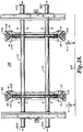
Fig. 42 is an elevation view of a pair of mounts according to embodiments of the invention mounted on a wall, the cross-supports of each mount being shifted to a side of the mount; -
Fig. 43a is an elevation view of a mount according to an embodiment of the invention mounted on the wall of a room wherein the ceiling is not parallel with the floor and the cross supports of the mount have been adjusted to parallel the ceiling; -
Fig. 43b is an elevation view of a mount according to an embodiment of the invention mounted on the wall of a room wherein the mount is slightly skewed and the cross supports of the mount have been adjusted to parallel the ceiling and floor of the room; -
Fig. 44 is a front perspective view of an alternative embodiment of a mounting system according to the invention; and -
Fig. 45 is a front elevation view of a non-height adjustable embodiment of a mount according to the invention. - While the invention is amenable to various modifications and alternative forms, specifics thereof have been depicted by way of example in the drawings and will be described in detail. It should be understood, however, that the intention is not to limit the invention to the particular embodiments described. On the contrary, the intention is defined by
claim 1. - Mounting
system 100 for mounting a flat panelelectronic display 102, and optionally a peripheral device such as aDVD player 104, on awall 106 is depicted generally inFigures 1 and1A . Mountingsystem 100 generally includeswall brackets display interface brackets - As depicted generally in
Figures 2-13 ,wall brackets image guide members carrier assembly 124, and endcaps guide member wall interface flange 130 withguide flange 132 projecting perpendicularly therefrom. Eachwall interface flange 130 has an upper 134 and a lower 136 end portion, each defining an elongaterounded notch 138. When inwardly extendingportions guide member 120 are registered and mated with inwardly extendingportions guide member 122, theguide flanges 132 ofguide members rounded notches 138 ofend portions guide flange 132 defines a pair ofelongate slots -
Carrier assembly 124 generally includes mirrorimage body plates spherical bearing assemblies 152, andcoupling members body plate cross-support apertures fastener holes Spherical bearing assembly 152 generally includes mirrorimage housing halves housing half aperture 172 having an inwardly oriented sphericalinner surface 174 conforming toouter surface 176 ofbearing 170. Housing halves 166, 168, are mated, withinner surface 178 ofhousing half 166 confrontinginner surface 180 ofhousing half 168 andapertures 172 registered to definehousing 182. Bearing 170 is captured inapertures 172 withouter surface 176 confrontinginner surfaces 174. Couplingmembers end flange 184 defining threadedaperture 186, and projectinglegs elongate aperture 192 and a vertically orientedaperture 194. - Coupling
members ends body plates Spherical bearing assemblies 152 are also received betweenbody plates cross-support apertures Fasteners 200 extend throughfastener holes housing halves fastener holes 208 incoupling members carrier assembly 124 to secure the assembly together. -
Carrier assembly 124 is received betweenguide flanges 132 ofguide members Figure 2 . Guide pins 210, 212, respectively extend throughelongate slots apertures 214 inend caps Carrier assembly 124 is thus vertically slidable betweenguide members guide pins slots - End caps 126, 128, are received on upper and
lower end portions guide members apertures 216. A height adjustment control in the form of verticalposition adjustment screw 218 extends through vertically orientedaperture 194 inend cap 126 and threads into threadedaperture 186. As verticalposition adjustment screw 218 is rotated,carrier assembly 124 slides betweenguide members Fig. 2a , guidemembers end flanges 120a, 120b, 122a, 122b, respectively, and are connected with end connectors 126a, 128a, respectively. Cosmetic caps (not depicted) may be fitted overend connectors 126a, 128b, for aesthetic purposes if desired. In another alternative embodiment depicted inFig. 44 ,wall brackets lower frame members - Mirror image
display interface brackets Figures 14-26 , each generally includingdisplay interface member 220,hook plates 222, and optionally one or both ofupper latch assembly 224, andlower latch assembly 226.Display interface member 220 generally includes displayinterface channel portion 228 withguide flange portion 230 extending perpendicularly thereto. Display interface channel portion defines a plurality of apertures, some of which may be rounded 232, and some of which may be elongate 234, for receiving fasteners to attach flat panelelectronic display 102 ondisplay receiving surface 236.Guide flange portion 230 definesguide structures 237 in the form ofslots structures 237 may also be configured as other structures fulfilling the same purpose, such as for example, channels, grooves, recesses, ridges, cam surfaces, or the like. Further, it will be appreciated that guidestructures 237 may be arcuate, angular, or straight in shape.Guide flange portion 230 further definesfriction slot 242. - Each
hook plate 222 defines guide structures 244, configured asslots Upper end 250 definesupper hook 252, whilelower end 254 defineslower hook 256. Again, although depicted as slots, it will be appreciated that guide structures 244 may also be configured as other structures fulfilling the same purpose, such as for example, channels, grooves, recesses, ridges, cam surfaces, or the like. Further, it will be appreciated that guide structures 244 may be arcuate, angular, or straight in shape. As depicted inFigures 14, 16 , and21 ,upper end 250 may further definelatch guide slot 258 andlatch adjustment aperture 260. As depicted inFigures 22-26 ,lower end 254 may further define latch guides 262, 264, andspring pin guide 266.Friction screw aperture 268 extends throughhook plate 222intermediate slots - As depicted in
Figures 18 and 19 ,upper latch assembly 224 generally includeslatch plate 270, guide 272, guideretainer 274, andfastener 276.Latch plate 270 defines gearedaperture 278 andguide slot 280.Shank portion 282 ofguide 272 extends throughlatch guide slots 258 of bothhook plates 222 andguide slot 280 oflatch plate 270.Guide 272 is retained withguide retainer 274 andfastener 276.Geared aperture 278 is registered withlatch adjustment aperture 260 of eachhook plate 222.Teeth 282 in gearedaperture 278 may be configured to mesh with the tip of a standard Phillips screwdriver. -
Lower latch assembly 226 as depicted inFigures 22-26 generally includeslatch plate 284,spring 286, andspring slide 288.Latch plate 284 defines spring aperture 290 andguide pin apertures 292.Spring slide 288 is received in spring aperture 290 withnotches 294 engaged with opposite sides. One end ofspring 286 is received overtab 296 with the opposite end bearing onspring slide 288. Guide pins 298 are received in each ofapertures 292 and are retained in position withretainers 300.Latch plate 284 is received between lower ends 254 ofhook plates 222, with lateral ends 302 ofspring slide 288 projecting through spring pin guides 266, and the outer ends of guide pins 298 received in latch guides 262, 264. -
Guide pin 304 extends throughslot 238 and theguide slots 246 of bothhook plates 222, whileguide pin 306 extends throughslot 240 and guideslots 248 of bothhook plates 222. Eachguide pin retainer 308.Friction screw 310 extends throughfriction slot 242 andfriction screw aperture 268 in each ofhook plates 222 and is secured withknob 312.Friction washers 314 are positioned on each side betweenguide flange portion 230 andhook plate 222. - During installation,
wall brackets wall 106 withfasteners 316 throughelongate apertures 192 inend caps Figure 28 , preferably into a load bearing member ofwall 106 such as a stud.Wall brackets floor 318 so as to minimize the amount of adjustment needed. It will be appreciated thatelongate apertures 192 enable the top and bottom of each ofwall brackets fasteners 316 are tightened in order to ensure proper vertical alignment. - Once
fasteners 316 are tightened, cross-supports 112 may be inserted through the horizontally registered spherical bearings of thewall brackets Cross-supports 112 are freely slidable throughbearings 170. If not initially registered, horizontally correspondingbearings 170 ofwall brackets wall brackets carrier assemblies 124 to move vertically. Withcross-supports 112 in place, vertical position adjustment screws 218 can also be operated so as to raise or lower the height ofcross-supports 112 abovefloor 318, to level cross-supports 112, or to otherwise adjust the orientation ofcross-supports 112 relative to other structures in the room such as corners or furniture. In embodiments of the invention, thecarrier assembly 124 of eachwall bracket Spherical bearing assemblies 152 enablecross-supports 112 to be oriented out of perpendicular with thecarrier assemblies 124, thereby enabling independent shifting ofcarrier assemblies 124 without binding. - For example, as depicted in
Figure 43a , cross-supports 112 may be adjusted to parallel aceiling 320 that is not parallel withfloor 318. As depicted, the ends ofupper cross-support 112 are both the same distance H1 belowceiling 320, while the ends oflower cross-support 112, which is parallel with the upper cross-support, are at differing distances H3, H4, abovefloor 318. When anelectronic display 102 is coupled with cross supports 112, the top and bottom edges of theelectronic display 102 will be parallel withceiling 320. In another example depicted inFig. 43b , mount 100 may be installed such thatwall brackets floor 318.Carrier assembly 124 of eachwall bracket ceiling 320 orfloor 318. When anelectronic display 102 is coupled withcross-supports 112, the top and bottom edges of theelectronic display 102 will be parallel withceiling 320 andfloor 318. - With
cross-supports 112 inserted throughbearings 170 ofwall brackets cross-supports 112 to preventcross-supports 112 from being withdrawn. In embodiments of the invention, cross-supports 112 are laterally slidable withinbearings 170 even withend caps 320 in place so as to enable a wider range of lateral positioning relative to wallbrackets Fig. 42 ,cross-supports 112 may be shifted to one side or the other, such thatmount 100 can be located wherever necessary onwall 106 to ensure fastening to studs or other support structure withinwall 106. As also depicted inFig. 42 , the ability to laterally shiftcross-supports 112 may also facilitate the assemblage of multi display arrays ofelectronic display devices 102.Displays 102 can be positioned relative to each other without the necessity of ensuring uniform lateral spacing ofmounts 100. -
Display interface brackets display 102 with fasteners throughapertures round apertures 232 and theelongate apertures 234 enablebrackets display 102. -
Display 102 withdisplay interface brackets cross-supports 112 by hookingupper hook 252 of eachbracket top cross-support 112 andlower hook 256 of eachbracket bottom cross-support 112. Ifbrackets upper latch assembly 224, thelatch assembly 224 may be engaged by inserting a Phillips screwdriver throughaperture 260, engaging the tip of the screwdriver withteeth 282, and rotating the screwdriver. As the screwdriver rotates, guide 272 slides inguide slots 258 and tip 324 oflatch plate 270 is urged aroundcross-support 112 to close the latch. Disengagement is the reverse of engagement - If
brackets lower latch assembly 226,tip 326 oflatch plate 284 encountersbottom cross-support 112 aslower hook 256 is engaged.Latch plate 284 rotates against the bias provided byspring 286 withpins 298 sliding inguides spring slide 288 sliding inguides 266. Once sufficient clearance exists betweentip 326 andupper edge 328 oflower hook 256 to enable passage ofcross-support 112, the bias ofspring 286 urges latchplate 284 to snap back into position withlower hook 256 engaged aroundcross-support 112. Disengagement is accomplished by pulling outward on the bottom ofdisplay 102 with sufficient force to overcome the bias ofspring 286, thereby causinglatch plate 284 to rotate in the opposite direction. - With
display 102 coupled tocross-supports 112, the tilt position of the display may then be adjusted as depicted inFigure 27 . Withknob 312 loosened so as to reduce friction,display 102 may be tilted to a desired position by pulling the top of the display away, or pushing the top of the display toward,wall 106.Guide pin 304 slides or rolls inslot 238 and theguide slots 246 of bothhook plates 222, whileguide pin 306 slides or rolls inslot 240 and guideslots 248 of bothhook plates 222 to enable tilting. Because of the orientation ofslots slots display 102 pivots about a horizontal pivot axis X-X extending through thedisplay 102 forward a distance Y of thedisplay receiving surface 236 and down a distance Z from a horizontal midline B-B of thedisplay 102. With this configuration,display 102 is tiltable in either direction with a minimum of effort and tends to remain in position even withknob 312 loose. Once a desired tilt position is reached, however, knobs 312 may be tightened to apply frictional resistance to holddisplay 102 in the tilt position. Further teachings relating to the optimal orientation ofguide slots PCT/US2008/000117 , hereby fully incorporated herein by reference. - Shelf assembly 118 is depicted in
Figures 29-31 and generally includeshook assemblies 322,slide 324,shelf support 326 andshelf 328.Hook assembly 322 generally includesuprights 330,hook portion 332 andcross-member 334.Slide 324 generally includeschannels 336 andcross-member 338. Each ofchannels 336 defines a plurality ofelongate apertures 340.Shelf support 326 generally includeslateral members 342 and backplane 344. - As depicted in
Fig. 1a ,hook portion 332 hooks overcross-support 112 to suspend shelf assembly 118 from the mount.Uprights 330 are coupled to slide 324 with fasteners extending throughelongate apertures 340. With these fasteners loosened,uprights 330 are slidable relative to slide 324 to adjust height H1 ofcross-member 112 aboveshelf 328.Shelf 328 may be made from transparent material such as glass, or from opaque materials, depending on the aesthetic effects desired. - An alternative embodiment of a
shelf assembly 346 is depicted inFigs. 37-38 .Shelf assembly 346 generally includesextrusion 348,shelf support 350 andhook assembly 352.Extrusion 348 may be, for example, an aluminum extrusion having a cross-section as depicted inFig. 36 .Shelf support 350 generally includes a pair ofchannels 354 connected with aback plane coupler 356.Shelf support 350 is attached toextrusion 348 withfastener 358.Hook assembly 352 generally includescoupler 360 and hooks 362.Hooks 362 may be equipped with a latch assembly similar to previously describedupper latch assembly 224.Hook assembly 352 is attached toextrusion 348 withfasteners 364. It will be appreciated thathook assembly 352 may be attached at any desired location alongextrusion 348 in order to adjust the position of a shelf resting onshelf support 350 relative to cross-supports 112. In use, hooks 362 are engaged overcross-support 112 in a similar fashion as for the hooks of shelf assembly 118 as previously described. -
Accessory attachment 366 as depicted inFigs. 32-36 may be used to attach various accessories and peripheral devices, such asspeaker 368 to mountingsystem 100.Accessory attachment 366 generally includesextrusion 370,hook assembly 372 anddevice interface 374.Extrusion 370 may be, for example, an aluminum extrusion having a cross-section as depicted inFig. 36 .Hook assembly 372 is attached toextrusion 370 withfasteners 376. It will be appreciated thathook assembly 372 may be attached at any desired location alongextrusion 370 in order to adjust the position ofdevice interface 374 and an attached device relative to cross-supports 112.Device interface 374 generally includeschannel 378 andcouplers 380.Couplers 380 are attached to channel 378 withfasteners 382 extending throughslot 384 such thatcouplers 380 are selectively slidable alongchannel 378. Eachcoupler 380 defines anaperture 386 for receiving a fastener (not depicted) to attach a desired device such asspeaker 368. In use,hook assembly 372 is engaged overcross-support 112 as depicted inFig. 32 to suspend theaccessory attachment 366 from mountingsystem 100. - In
Fig. 45 there is depicted a non-height adjustable version of amount 604.Mount 604 generally includesframe 606 having a pair of forwardly projectingflanges 608, 610.Cross-supports 112 are received through apertures in each offlanges 608, 610, with bearinghalves 612 on each side of the flange.Cross-supports 112 are laterally slidable as in the vertically adjustable version depicted inFig. 42 , thereby enabling a greater range of positioning formount 604 onwall 106. It will be appreciated thatmount 604 can be used alone in applications where height adjustability is not needed. It will also be appreciated thatmount 604 can be used with one or more ofmounts 100 to form multi-element arrays where some of the display elements are to be fixed in position and other elements of the array are to be tiltable or height adjustable. - In a further embodiment of the invention, speakers may be laterally attached so as to project on each side of the electronic display using
speaker attachments 388 as depicted inFigs. 39-41 . Eachspeaker attachment 388 generally includesinterface channel 390,rods 392 andcoupler 394.Small end 396 ofcoupler 394 is received in the end ofcross-support 112.Coupler 394 definescentral bore 398 which slidably receivesrod 392. Eachrod 392 is coupled tochannel 388.Channel 388 definesslot 400 for receiving fasteners (not depicted) to attach a speaker to the channel. - It will be appreciated that
mount 100 and components thereof can be effectively distributed by packaging one or more of the described mount components in kit form along withuser instructions 500 for assembling and attachingmount 100 to awall 106,coupling display 102 to mount 100 and adjusting the position ofcross-supports 112 and the tilt position ofdisplay interface brackets display 102 as desired.User instructions 500 may be provided in printed form as depicted inFig. 1a ., or in other formats such as video, CD or DVD. - The embodiments above are intended to be illustrative and not limiting. Additional embodiments are encompassed within the scope of the claims. Although the present invention has been described with reference to particular embodiments, those skilled in the art will recognize that changes may be made in form and detail without departing from the spirit and scope of the invention. For purposes of interpreting the claims for the present invention, it is expressly intended that the provisions of
Section 112, sixth paragraph of 35 U.S.C. are not to be invoked unless the specific terms "means for" or "step for" are recited in a claim. - The present invention relates generally to mounting devices for electronic displays and more particularly, to devices for mounting flat-screen electronic displays and associated peripheral devices to vertical surfaces.
- Flat-screen electronic display devices such as LCD and plasma displays are popular among consumers. A highly desirable feature that has, in large part, led to the' popularity οf these displays is the attractive aesthetic of a thin display device that can be mounted on a wall so as to resemble a framed photograph or painting. Amount according to the preamble of
claim 1 is known fromWO2006/127826 . - Accordingly, numerous mounting devices and structures have been developed for mounting flat panel electronic displays to walls and other elements of structures. A typical drawback of these previous mounting devices, however, is that strict attention must be paid during installation of the mounting device to ensure that the display will be mounted in the optimal position on the structure and that the display will be level or aligned with the structure. Even a very small error in positioning of the mounting device during installation can result in a highly noticeable misalignment of the display when mounted, thereby detracting significantly from the aesthetics of the display installation.
- Due to the location of structural elements such as wall framing members, it is often difficult to position a display mount in precisely the position desired on a wall surface. Further, fasteners used to fasten the mounting device to the wall typically lack precision and may shift during the installation process, leading to misalignment of the mounting device.
- What is needed in the industry is a mounting device for electronic display devices that enables precision post-installation adjustment of mount and display device position relative to the structure upon which they are mounted.
- The invention is defined by
claim 1. - A display mount with post-installation adjustment features according to embodiments of the present disclosure addresses the above-mentioned needs of the industry. The mount may include two or more wall brackets, each having a vertically shiftable carrier assembly Cross-supports extend between the carrier assemblies and are received in floating connection structures in the carriers. An electronic display display is coupled with the cross-supports. The carrier assembly of each wall bracket is independently vertically shiftable to shift the orientation of the cross-supports, and thereby adjust the vertical position and orientation of the electronic display device coupled with the cross-supports. The electronic display may be coupled to the cross-supports with display interface brackets which are tilt-adjustable to change the tilt position of the display device.
- According to an embodiment, a mount for attaching an electronic display to a fixed structure includes a structure interface portion with a pair of horizontally spaced apart wall brackets and a pair of elongate cross supports. Each wall bracket includes a carrier portion, the cross supports vertically spaced apart and extending between the carrier portions of the wall brackets. The carrier portion of each wall bracket is separately vertically positionable to alter the orientation of the cross supports relative to the fixed structure. The mount further includes at least one display interface bracket received on the cross supports. Each carrier portion may include a pair of floating connection structures, each floating connection structure receiving a separate one of the cross supports. The floating connection structures may be spherical bearings.
- In embodiments of the invention, the cross supports are separately horizontally shiftable relative to the wall brackets. The at least one display interface bracket may include a tilt mechanism, the tilt mechanism enabling an electronic display device attached to the at least one display interface bracket to be selectively tilted about a generally horizontal tilt axis. The tilt axis may be positioned forward of a display receiving surface of the bracket such that the tilt axis extends through the electronic display device. The structure interface portion may include one or more frame members coupling the wall brackets.
- In other embodiments, an electronic display system includes an electronic display device and a mount for attaching the electronic display device to a fixed structure. The mount includes a structure interface assembly and a display interface assembly, the structure interface assembly including a plurality of wall brackets and a plurality of cross supports. The wall brackets are horizontally spaced apart with each of the wall brackets including a guide structure and a carrier. The carrier is selectively vertically shiftable relative to the guide structure with a height adjustment control. The cross supports are vertically spaced apart and extend between the wall brackets. The cross supports are received in the carriers of the wall brackets such that the cross supports are vertically shiftable with the carriers. The display interface assembly includes a pair of display interface brackets spaced apart on the cross supports and the electronic display device received on the display interface brackets.
- In embodiments of the invention, each carrier may include a plurality of floating connection structures, each floating connection structure receiving a separate one of the cross supports. These floating connection structures may be spherical bearings. The cross supports may be separately horizontally shiftable relative to the wall brackets.
- In embodiments of the invention, each display interface bracket may include a tilt mechanism, the tilt mechanism enabling the electronic display device to be selectively tilted about a generally horizontal tilt axis. Each display interface bracket may present a display receiving surface and the tilt axis may be positioned forward of the display receiving surface such that the tilt axis extends through the electronic display device. The tilt axis can be positioned proximate a bottom edge of the electronic display device.
- In other embodiments of the invention, a display system may include a plurality of electronic display devices and a plurality of mounts, each electronic display device mounted on a separate one of the mounts.
- In further embodiments, a mount for attaching an electronic display to a fixed structure includes a structure interface with a pair of horizontally spaced apart wall brackets and a pair of elongate cross supports. Each wall bracket includes a carrier slidably shiftable in a guide structure, the carrier including a pair of floating connection structures. The cross supports are vertically spaced apart and extend between the carriers of the wall brackets, each cross support received in a separate one of the floating connection structures of each carrier. The mount further includes at least one display interface bracket received on the cross supports.
- In other embodiments, a mount according to the invention may include a shelf assembly operably coupled with one or more of the cross supports, or a speaker attachment operably coupled with one or more of the cross supports.
- The invention may be more completely understood in consideration of the following detailed description of various embodiments of the invention in connection with the following drawings, in which:
-
Fig. 1 is a front perspective view of an electronic display and peripheral device mounted on a wall with a mount according to an embodiment of the present invention; -
Fig. 1a is a front perspective view of a mount according to an embodiment of the present invention; -
Fig. 2 is a front perspective view of a wall interface of the mount depicted inFig. 1a ; -
Fig. 2a is a front perspective view of an alternative embodiment of a wall interface of the mount depicted inFig. 1a ; -
Fig. 3 is a perspective view of a first guide member of the wall interface ofFig. 1a ; -
Fig. 4 is a perspective view of another guide member of the wall interface ofFig. 1a ; -
Fig. 5 is partial cutaway view of the wall interface ofFig. 1a ; -
Fig. 6 is fragmentary cross-sectional view taken at section 6-6 ofFig. 1 a; -
Fig. 7 is perspective view of an end cap portion of the wall interface ofFig. 1a ; -
Fig. 8 is a front elevation view of the end cap ofFig. 7 ; -
Fig. 9 is a perspective view of a coupling member of the wall interface ofFig. 1 a -
Fig. 10 is an exploded view of a spherical bearing assembly of the wall interface ofFig. 1a ; -
Fig. 11 is a perspective view of a body plate of the wall interface ofFig. 1a ; -
Fig. 12 is a side elevation view of the body plate ofFig. 11 ; -
Fig. 13 is a front elevation view of the body plate ofFig. 11 ; -
Fig. 14 is a perspective view of a tilt bracket assembly of the mount ofFig. 1a ; -
Fig. 15 is a perspective view of a display interface member of the tilt bracket assembly ofFig. 14 ; -
Fig. 16 is a perspective view of a hook plate of the tilt bracket assembly ofFig. 14 ; -
Fig. 17 is an elevation view of a latch plate of the tilt bracket assembly ofFig. 14 ; -
Fig. 18 is a fragmentary perspective view of an upper latch assembly of the tilt bracket assembly ofFig. 14 ; -
Fig. 19 is an exploded view of the upper latch assembly ofFig. 18 ; -
Fig. 20 is a fragmentary rear elevation view of a portion of the tilt bracket assembly ofFig. 14 ; -
Fig. 21 is a side elevation view of the tilt bracket assembly ofFig. 14 ; -
Fig. 22 is a fragmentary perspective view of a lower latch assembly of an alternative embodiment of the tilt bracket assembly ofFig. 14 ; -
Fig. 23 is a cut-away view of the lower latch assembly ofFig. 22 ; -
Fig. 24 is a perspective view of the hook plate of the embodiment ofFig. 22 ; -
Fig. 25 is a perspective view of the latch plate of the lower latch assembly ofFig. 22 ; -
Fig. 26 is a perspective view of the spring slide of the lower latch assembly ofFig. 22 : -
Fig. 27 is a side elevation view of a mount and display according to an embodiment of the present invention depicting the tilt motion of the mount; -
Fig. 28 is a front elevation view of a mount according to an embodiment of the invention; -
Fig. 29 is a perspective view of a shelf attachment for the mount ofFig. 1a ; -
Fig. 30 is a fragmentary perspective view of the hook assemblies of the shelf attachment ofFig. 29 ; -
Fig. 31 is a bottom perspective view of the shelf assembly ofFig. 29 without the shelf; -
Fig. 32 is a front perspective view of a mount and accessory attachment according to an embodiment of the invention; -
Fig. 33 is a fragmentary view of a portion of the mount ofFig. 32 ; -
Fig. 34 is a rear perspective view of the accessory attachment depicted inFig. 32 ; -
Fig. 35 is a front perspective view of the accessory attachment depicted inFig. 32 ; -
Fig. 36 is an end view of the extrusion portion of the accessory attachment ofFig. 35 ; -
Fig. 37 is a perspective view of an alternative embodiment of a shelf attachment; -
Fig. 38 is a rear perspective view of the shelf attachment ofFig. 37 ; -
Fig. 39 is a front perspective view of side speaker attachments with a mount according to an embodiment of the invention; -
Fig. 40 is a fragmentary perspective view of a side speaker attachment; -
Fig. 41 is a perspective view of an insert portion of the side speaker attachment ofFig. 40 ; -
Fig. 42 is an elevation view of a pair of mounts according to embodiments of the invention mounted on a wall, the cross-supports of each mount being shifted to a side of the mount; -
Fig. 43a is an elevation view of a mount according to an embodiment of the invention mounted on the wall of a room wherein the ceiling is not parallel with the floor and the cross supports of the mount have been adjusted to parallel the ceiling; -
Fig. 43b is an elevation view of a mount according to an embodiment of the invention mounted on the wall of a room wherein the mount is slightly skewed and the cross supports of the mount have been adjusted to parallel the ceiling and floor of the room; -
Fig. 44 is a front perspective view of an alternative embodiment of a mounting system according to the invention; and -
Fig. 45 is a front elevation view of a non-height adjustable embodiment of a mount according to the invention. - While the invention is amenable to various modifications and alternative forms, specifics thereof have been depicted by way of example in the drawings and will be described in detail. It should be understood, however, that the intention is not to limit the invention to the particular embodiments described. On the contrary, the intention is defined by
claim 1. - Mounting
system 100 for mounting a flat panelelectronic display 102, and optionally a peripheral device such as aDVD player 104, on awall 106 is depicted generally inFigures 1 and1A . Mountingsystem 100 generally includeswall brackets display interface brackets - As depicted generally in
Figures 2-13 ,wall brackets image guide members carrier assembly 124, and endcaps guide member wall interface flange 130 withguide flange 132 projecting perpendicularly therefrom. Eachwall interface flange 130 has an upper 134 and a lower 136 end portion, each defining an elongaterounded notch 138. When inwardly extendingportions guide member 120 are registered and mated with inwardly extendingportions guide member 122, theguide flanges 132 ofguide members rounded notches 138 ofend portions guide flange 132 defines a pair ofelongate slots -
Carrier assembly 124 generally includes mirrorimage body plates spherical bearing assemblies 152, andcoupling members body plate cross-support apertures fastener holes Spherical bearing assembly 152 generally includes mirrorimage housing halves bearing 170. Eachhousing half aperture 172 having an inwardly oriented sphericalinner surface 174 conforming toouter surface 176 ofbearing 170. Housing halves 166, 168, are mated, withinner surface 178 ofhousing half 166 confrontinginner surface 180 ofhousing half 168 andapertures 172 registered to definehousing 182. Bearing 170 is captured inapertures 172 withouter surface 176 confrontinginner surfaces 174. Couplingmembers end flange 184 defining threadedaperture 186, and projectinglegs elongate aperture 192 and a vertically orientedaperture 194. - Coupling
members ends body plates Spherical bearing assemblies 152 are also received betweenbody plates cross-support apertures Fasteners 200 extend throughfastener holes housing halves fastener holes 208 incoupling members carrier assembly 124 to secure the assembly together. -
Carrier assembly 124 is received betweenguide flanges 132 ofguide members Figure 2 . Guide pins 210, 212, respectively extend throughelongate slots apertures 214 inend caps Carrier assembly 124 is thus vertically slidable betweenguide members guide pins slots - End caps 126, 128, are received on upper and
lower end portions guide members apertures 216. A height adjustment control in the form of verticalposition adjustment screw 218 extends through vertically orientedaperture 194 inend cap 126 and threads into threadedaperture 186. As verticalposition adjustment screw 218 is rotated,carrier assembly 124 slides betweenguide members Fig. 2a , guidemembers end flanges 120a, 120b, 122a, 122b, respectively, and are connected with end connectors 126a, 128a, respectively. Cosmetic caps (not depicted) may be fitted overend connectors 126a, 128b, for aesthetic purposes if desired. In another alternative embodiment depicted inFig. 44 ,wall brackets lower frame members - Mirror image
display interface brackets Figures 14-26 , each generally includingdisplay interface member 220,hook plates 222, and optionally one or both ofupper latch assembly 224, andlower latch assembly 226.Display interface member 220 generally includes displayinterface channel portion 228 withguide flange portion 230 extending perpendicularly thereto. Display interface channel portion defines a plurality of apertures, some of which may be rounded 232, and some of which may be elongate 234, for receiving fasteners to attach flat panelelectronic display 102 ondisplay receiving surface 236.Guide flange portion 230 definesguide structures 237 in the form ofslots structures 237 may also be configured as other structures fulfilling the same purpose, such as for example, channels, grooves, recesses, ridges, cam surfaces, or the like. Further, it will be appreciated that guidestructures 237 may be arcuate, angular, or straight in shape.Guide flange portion 230 further definesfriction slot 242. - Each
hook plate 222 defines guide structures 244, configured asslots Upper end 250 definesupper hook 252, whilelower end 254 defineslower hook 256. Again, although depicted as slots, it will be appreciated that guide structures 244 may also be configured as other structures fulfilling the same purpose, such as for example, channels, grooves, recesses, ridges, cam surfaces, or the like. Further, it will be appreciated that guide structures 244 may be arcuate, angular, or straight in shape. As depicted inFigures 14, 16 , and21 ,upper end 250 may further definelatch guide slot 258 andlatch adjustment aperture 260. As depicted inFigures 22-26 ,lower end 254 may further define latch guides 262, 264, andspring pin guide 266.Friction screw aperture 268 extends throughhook plate 222intermediate slots - As depicted in
Figures 18 and 19 ,upper latch assembly 224 generally includeslatch plate 270, guide 272, guideretainer 274, andfastener 276.Latch plate 270 defines gearedaperture 278 andguide slot 280.Shank portion 282 ofguide 272 extends throughlatch guide slots 258 of bothhook plates 222 andguide slot 280 oflatch plate 270.Guide 272 is retained withguide retainer 274 andfastener 276.Geared aperture 278 is registered withlatch adjustment aperture 260 of eachhook plate 222.Teeth 282 in gearedaperture 278 may be configured to mesh with the tip of a standard Phillips screwdriver. -
Lower latch assembly 226 as depicted inFigures 22-26 generally includeslatch plate 284,spring 286, andspring slide 288.Latch plate 284 defines spring aperture 290 andguide pin apertures 292.Spring slide 288 is received in spring aperture 290 withnotches 294 engaged with opposite sides. One end ofspring 286 is received overtab 296 with the opposite end bearing onspring slide 288. Guide pins 298 are received in each ofapertures 292 and are retained in position withretainers 300.Latch plate 284 is received between lower ends 254 ofhook plates 222, with lateral ends 302 ofspring slide 288 projecting through spring pin guides 266, and the outer ends of guide pins 298 received in latch guides 262, 264. -
Guide pin 304 extends throughslot 238 and theguide slots 246 of bothhook plates 222, whileguide pin 306 extends throughslot 240 and guideslots 248 of bothhook plates 222. Eachguide pin retainer 308.Friction screw 310 extends throughfriction slot 242 andfriction screw aperture 268 in each ofhook plates 222 and is secured withknob 312.Friction washers 314 are positioned on each side betweenguide flange portion 230 andhook plate 222. - During installation,
wall brackets wall 106 withfasteners 316 throughelongate apertures 192 inend caps Figure 28 , preferably into a load bearing member ofwall 106 such as a stud.Wall brackets floor 318 so as to minimize the amount of adjustment needed. It will be appreciated thatelongate apertures 192 enable the top and bottom of each ofwall brackets fasteners 316 are tightened in order to ensure proper vertical alignment. - Once
fasteners 316 are tightened, cross-supports 112 may be inserted through the horizontally registered spherical bearings of thewall brackets Cross-supports 112 are freely slidable throughbearings 170. If not initially registered, horizontally correspondingbearings 170 ofwall brackets wall brackets carrier assemblies 124 to move vertically. Withcross-supports 112 in place, vertical position adjustment screws 218 can also be operated so as to raise or lower the height ofcross-supports 112 abovefloor 318, to level cross-supports 112, or to otherwise adjust the orientation ofcross-supports 112 relative to other structures in the room such as corners or furniture. In embodiments of the invention, thecarrier assembly 124 of eachwall bracket Spherical bearing assemblies 152 enablecross-supports 112 to be oriented out of perpendicular with thecarrier assemblies 124, thereby enabling independent shifting ofcarrier assemblies 124 without binding. - For example, as depicted in
Figure 43a , cross-supports 112 may be adjusted to parallel aceiling 320 that is not parallel withfloor 318. As depicted, the ends ofupper cross-support 112 are both the same distance H1 belowceiling 320, while the ends oflower cross-support 112, which is parallel with the upper cross-support, are at differing distances H3, H4, abovefloor 318. When anelectronic display 102 is coupled with cross supports 112, the top and bottom edges of theelectronic display 102 will be parallel withceiling 320. In another example depicted inFig. 43b , mount 100 may be installed such thatwall brackets floor 318.Carrier assembly 124 of eachwall bracket ceiling 320 orfloor 318. When anelectronic display 102 is coupled withcross-supports 112, the top and bottom edges of theelectronic display 102 will be parallel withceiling 320 andfloor 318. - With
cross-supports 112 inserted throughbearings 170 ofwall brackets cross-supports 112 to preventcross-supports 112 from being withdrawn. In embodiments of the invention, cross-supports 112 are laterally slidable withinbearings 170 even withend caps 320 in place so as to enable a wider range of lateral positioning relative to wallbrackets Fig. 42 ,cross-supports 112 may be shifted to one side or the other, such thatmount 100 can be located wherever necessary onwall 106 to ensure fastening to studs or other support structure withinwall 106. As also depicted inFig. 42 , the ability to laterally shiftcross-supports 112 may also facilitate the assemblage of multi display arrays ofelectronic display devices 102.Displays 102 can be positioned relative to each other without the necessity of ensuring uniform lateral spacing ofmounts 100. -
Display interface brackets display 102 with fasteners throughapertures round apertures 232 and theelongate apertures 234 enablebrackets display 102. -
Display 102 withdisplay interface brackets cross-supports 112 by hookingupper hook 252 of eachbracket top cross-support 112 andlower hook 256 of eachbracket bottom cross-support 112. Ifbrackets upper latch assembly 224, thelatch assembly 224 may be engaged by inserting a Phillips screwdriver throughaperture 260, engaging the tip of the screwdriver withteeth 282, and rotating the screwdriver. As the screwdriver rotates, guide 272 slides inguide slots 258 and tip 324 oflatch plate 270 is urged aroundcross-support 112 to close the latch. Disengagement is the reverse of engagement - If
brackets lower latch assembly 226,tip 326 oflatch plate 284 encountersbottom cross-support 112 aslower hook 256 is engaged.Latch plate 284 rotates against the bias provided byspring 286 withpins 298 sliding inguides spring slide 288 sliding inguides 266. Once sufficient clearance exists betweentip 326 andupper edge 328 oflower hook 256 to enable passage ofcross-support 112, the bias ofspring 286 urges latchplate 284 to snap back into position withlower hook 256 engaged aroundcross-support 112. Disengagement is accomplished by pulling outward on the bottom ofdisplay 102 with sufficient force to overcome the bias ofspring 286, thereby causinglatch plate 284 to rotate in the opposite direction. - With
display 102 coupled tocross-supports 112, the tilt position of the display may then be adjusted as depicted inFigure 27 . Withknob 312 loosened so as to reduce friction,display 102 may be tilted to a desired position by pulling the top of the display away, or pushing the top of the display toward,wall 106.Guide pin 304 slides or rolls inslot 238 and theguide slots 246 of bothhook plates 222, whileguide pin 306 slides or rolls inslot 240 and guideslots 248 of bothhook plates 222 to enable tilting. Because of the orientation ofslots slots display 102 pivots about a horizontal pivot axis X-X extending through thedisplay 102 forward a distance Y of thedisplay receiving surface 236 and down a distance Z from a horizontal midline B-B of thedisplay 102. With this configuration,display 102 is tiltable in either direction with a minimum of effort and tends to remain in position even withknob 312 loose. Once a desired tilt position is reached, however, knobs 312 may be tightened to apply frictional resistance to holddisplay 102 in the tilt position. Further teachings relating to the optimal orientation ofguide slots PCT/US2008/000117 , hereby fully incorporated herein by reference. - Shelf assembly 118 is depicted in
Figures 29-31 and generally includeshook assemblies 322,slide 324,shelf support 326 andshelf 328.Hook assembly 322 generally includesuprights 330,hook portion 332 andcross-member 334.Slide 324 generally includeschannels 336 andcross-member 338. Each ofchannels 336 defines a plurality ofelongate apertures 340.Shelf support 326 generally includeslateral members 342 and backplane 344. - As depicted in
Fig. 1a ,hook portion 332 hooks overcross-support 112 to suspend shelf assembly 118 from the mount.Uprights 330 are coupled to slide 324 with fasteners extending throughelongate apertures 340. With these fasteners loosened,uprights 330 are slidable relative to slide 324 to adjust height H1 ofcross-member 112 aboveshelf 328.Shelf 328 may be made from transparent material such as glass, or from opaque materials, depending on the aesthetic effects desired. - An alternative embodiment of a
shelf assembly 346 is depicted inFigs. 37-38 .Shelf assembly 346 generally includesextrusion 348,shelf support 350 andhook assembly 352.Extrusion 348 may be, for example, an aluminum extrusion having a cross-section as depicted inFig. 36 .Shelf support 350 generally includes a pair ofchannels 354 connected with aback plane coupler 356.Shelf support 350 is attached toextrusion 348 withfastener 358.Hook assembly 352 generally includescoupler 360 and hooks 362.Hooks 362 may be equipped with a latch assembly similar to previously describedupper latch assembly 224.Hook assembly 352 is attached toextrusion 348 withfasteners 364. It will be appreciated thathook assembly 352 may be attached at any desired location alongextrusion 348 in order to adjust the position of a shelf resting onshelf support 350 relative to cross-supports 112. In use, hooks 362 are engaged overcross-support 112 in a similar fashion as for the hooks of shelf assembly 118 as previously described. -
Accessory attachment 366 as depicted inFigs. 32-36 may be used to attach various accessories and peripheral devices, such asspeaker 368 to mountingsystem 100.Accessory attachment 366 generally includesextrusion 370,hook assembly 372 anddevice interface 374.Extrusion 370 may be, for example, an aluminum extrusion having a cross-section as depicted inFig. 36 .Hook assembly 372 is attached toextrusion 370 withfasteners 376. It will be appreciated thathook assembly 372 may be attached at any desired location alongextrusion 370 in order to adjust the position ofdevice interface 374 and an attached device relative to cross-supports 112.Device interface 374 generally includeschannel 378 andcouplers 380.Couplers 380 are attached to channel 378 withfasteners 382 extending throughslot 384 such thatcouplers 380 are selectively slidable alongchannel 378. Eachcoupler 380 defines anaperture 386 for receiving a fastener (not depicted) to attach a desired device such asspeaker 368. In use,hook assembly 372 is engaged overcross-support 112 as depicted inFig. 32 to suspend theaccessory attachment 366 from mountingsystem 100. - In
Fig. 45 there is depicted a non-height adjustable version of amount 604.Mount 604 generally includesframe 606 having a pair of forwardly projectingflanges 608, 610.Cross-supports 112 are received through apertures in each offlanges 608, 610, with bearinghalves 612 on each side of the flange.Cross-supports 112 are laterally slidable as in the vertically adjustable version depicted inFig. 42 , thereby enabling a greater range of positioning formount 604 onwall 106. It will be appreciated thatmount 604 can be used alone in applications where height adjustability is not needed. It will also be appreciated thatmount 604 can be used with one or more ofmounts 100 to form multi-element arrays where some of the display elements are to be fixed in position and other elements of the array are to be tiltable or height adj ustable. - In a further embodiment of the invention, speakers may be laterally attached so as to project on each side of the electronic display using
speaker attachments 388 as depicted inFigs. 39-41 . Eachspeaker attachment 388 generally includesinterface channel 390,rods 392 andcoupler 394.Small end 396 ofcoupler 394 is received in the end ofcross-support 112.Coupler 394 definescentral bore 398 which slidably receivesrod 392. Eachrod 392 is coupled tochannel 388.Channel 388 definesslot 400 for receiving fasteners (not depicted) to attach a speaker to the channel. - It will be appreciated that
mount 100 and components thereof can be effectively distributed by packaging one or more of the described mount components in kit form along withuser instructions 500 for assembling and attachingmount 100 to awall 106,coupling display 102 to mount 100 and adjusting the position ofcross-supports 112 and the tilt position ofdisplay interface brackets display 102 as desired.User instructions 500 may be provided in printed form as depicted inFig. 1a ., or in other formats such as video, CD or DVD. - The embodiments above are intended to be illustrative and not limiting. Additional embodiments are encompassed within the scope of the claims. Although the present invention has been described with reference to particular embodiments, those skilled in the art will recognize that changes may be made in form and detail without departing from the spirit and scope of the invention. For purposes of interpreting the claims for the present invention, it is expressly intended that the provisions of
Section 112, sixth paragraph of 35 U.S.C. are not to be invoked unless the specific terms "means for" or "step for" are recited in a claim.
Claims (7)
- A mount (100) for attaching an electronic display (102) to a fixed structure, the mount (100) comprising:
a structure interface portion comprising a pair of horizontally spaced apart wall brackets (108, 110) and a pair of elongate cross supports (112), each wall bracket (108, 110) including a carrier portion (124), the cross supports (112) vertically spaced apart and extending between the carrier portions (124) of the wall brackets (108, 110), at least one display interface bracket (114) received on the cross supports (112), the invention characterized in that the carrier portion (124) of each wall bracket (108, 110) is separately vertically positionable to alter the orientation of the cross supports (108, 110) relative to the fixed structure. - The mount (100) of claim 1, wherein each carrier portion (124) includes a pair of floating connection structures (152), each floating connection structure (152) receiving a separate one of the cross supports (112).
- The mount of claim 2, wherein the floating connection structures (152) are spherical bearings.
- The mount of claims 1-3, wherein the cross supports (112) are separately horizontally shiftable relative to the wall brackets (108, 110).
- The mount of claims 1-4, wherein the at least one display interface bracket (114) includes a tilt mechanism, the tilt mechanism enabling an electronic display device (102) attached to the at least one display interface bracket (114) to be selectively tilted about a generally horizontal tilt axis.
- The mount of claim 5, wherein the at least one display interface bracket (114) presents a display receiving surface and wherein the tilt axis is positioned forward of the display receiving surface such that the tilt axis extends through the electronic display device (102).
- The mount of claims 1-6, wherein the structure interface portion further comprises one or more frame members (606) coupling the wall brackets (108, 110).
Applications Claiming Priority (7)
| Application Number | Priority Date | Filing Date | Title |
|---|---|---|---|
| US1910408P | 2008-01-04 | 2008-01-04 | |
| US29/319,792 USD610437S1 (en) | 2008-06-15 | 2008-06-15 | Fixed two-rail mount for electronic display |
| US29/319,789 USD610436S1 (en) | 2008-01-04 | 2008-06-15 | Wall interface for display mount |
| US29/319,787 USD595277S1 (en) | 2008-01-04 | 2008-06-15 | Two-rail mount for electronic display |
| US29/319,788 USD612182S1 (en) | 2008-01-04 | 2008-06-15 | Shelf attachment for electronic display mount |
| US29/319,790 USD595702S1 (en) | 2008-01-04 | 2008-06-15 | Tilt adjustable display interface bracket |
| PCT/US2009/030147 WO2009089178A1 (en) | 2008-01-04 | 2009-01-05 | Display mount with post-installation adjustment features |
Publications (3)
| Publication Number | Publication Date |
|---|---|
| EP2238748A1 EP2238748A1 (en) | 2010-10-13 |
| EP2238748A4 EP2238748A4 (en) | 2011-12-07 |
| EP2238748B1 true EP2238748B1 (en) | 2018-08-22 |
Family
ID=40853433
Family Applications (1)
| Application Number | Title | Priority Date | Filing Date |
|---|---|---|---|
| EP09700554.0A Active EP2238748B1 (en) | 2008-01-04 | 2009-01-05 | Display mount with post-installation adjustment features |
Country Status (4)
| Country | Link |
|---|---|
| EP (1) | EP2238748B1 (en) |
| CN (1) | CN101971619B (en) |
| CA (1) | CA2711312C (en) |
| WO (1) | WO2009089178A1 (en) |
Families Citing this family (4)
| Publication number | Priority date | Publication date | Assignee | Title |
|---|---|---|---|---|
| US8333355B2 (en) | 2010-02-12 | 2012-12-18 | Peerless Industries, Inc. | Adjustable display mount |
| WO2017044622A1 (en) | 2015-09-09 | 2017-03-16 | Peerless Industries, Inc. | Video wall mount |
| US10443782B2 (en) | 2017-10-26 | 2019-10-15 | Peerless Industries, Inc. | Video wall mount |
| US11473722B2 (en) * | 2021-02-15 | 2022-10-18 | Walmart Apollo, Llc | Modular mounting apparatus for electronic device |
Family Cites Families (12)
| Publication number | Priority date | Publication date | Assignee | Title |
|---|---|---|---|---|
| US5069411A (en) * | 1990-10-10 | 1991-12-03 | Murphy James P | Picture hanger |
| DE20200148U1 (en) * | 2002-01-07 | 2002-07-18 | Reyl, Michael, Dipl.-Ing., 51065 Köln | Adjustable mounting device |
| US6604722B1 (en) * | 2002-06-10 | 2003-08-12 | Seng-Ling Tan | Display support |
| US6988696B2 (en) * | 2003-06-03 | 2006-01-24 | Delaware Capital Formation, Inc. | Mounting member with snap in swivel member |
| US20050087661A1 (en) * | 2003-10-23 | 2005-04-28 | Rabenius John A. | Method and apparatus for mounting flat screen television on vertically oriented surface |
| WO2006127826A2 (en) * | 2005-05-23 | 2006-11-30 | Don Burns | Display mounting apparatus |
| US7316379B1 (en) * | 2005-08-09 | 2008-01-08 | Graham Jonathan W | Adjustable mounting bracket for flat panel display |
| KR100723053B1 (en) * | 2005-08-22 | 2007-05-30 | 주식회사 대우일렉트로닉스 | Flat Panel Display Wall Mount |
| CN101005591A (en) * | 2006-01-16 | 2007-07-25 | 尹宇清 | Wall hanging telescopic frame for TV set |
| KR100797444B1 (en) * | 2006-03-27 | 2008-01-24 | 삼성전기주식회사 | Display extension device |
| KR100802384B1 (en) * | 2006-06-20 | 2008-02-14 | 삼성전기주식회사 | Display rotating device and how to combine it with display |
| GB2443267B (en) * | 2006-10-28 | 2010-01-27 | Wall Off | Visual display unit mount |
-
2009
- 2009-01-05 EP EP09700554.0A patent/EP2238748B1/en active Active
- 2009-01-05 CA CA2711312A patent/CA2711312C/en active Active
- 2009-01-05 CN CN200980105002.4A patent/CN101971619B/en active Active
- 2009-01-05 WO PCT/US2009/030147 patent/WO2009089178A1/en active Application Filing
Non-Patent Citations (1)
| Title |
|---|
| None * |
Also Published As
| Publication number | Publication date |
|---|---|
| EP2238748A1 (en) | 2010-10-13 |
| CN101971619B (en) | 2014-08-13 |
| CA2711312C (en) | 2016-08-02 |
| CA2711312A1 (en) | 2009-07-16 |
| CN101971619A (en) | 2011-02-09 |
| WO2009089178A1 (en) | 2009-07-16 |
| EP2238748A4 (en) | 2011-12-07 |
Similar Documents
| Publication | Publication Date | Title |
|---|---|---|
| US7823847B2 (en) | Display mount with post-installation adjustment features | |
| US8958200B2 (en) | Display mount with post-installation adjustment features | |
| US8542499B2 (en) | Multi-position mount for electronic display | |
| US8317146B2 (en) | Supporting device and dual display unit having the same | |
| EP2586195B1 (en) | Swing arm,tilt positionable mount for electronic display | |
| US7513474B2 (en) | Systems and methods for mounting flat panel video displays | |
| CA2674471C (en) | Device mount with selectively positionable tilt axis | |
| US8128049B2 (en) | Resilient mounting system with tilt capabilities | |
| CA2497543C (en) | Support for one or more flat panel displays | |
| EP1619438B1 (en) | Wall mounting structure for a flat panel display | |
| EP2238748B1 (en) | Display mount with post-installation adjustment features | |
| US20050242254A1 (en) | Mounting device for a flat screen display panel | |
| US7624959B2 (en) | Mounting device for a flat screen display panel | |
| US20120261362A1 (en) | Display support column | |
| US7905460B2 (en) | Hubs for wall mounting systems | |
| US20090020672A1 (en) | Supporting apparatus | |
| WO2008053242A1 (en) | Visual display unit mount | |
| US20060250347A1 (en) | Flat panel display mounting system | |
| WO2011085085A2 (en) | Display mount | |
| KR100944632B1 (en) | Computer monitor holding bracket located on a partition board | |
| US20050274858A1 (en) | Tilt lock box mount system | |
| KR102451486B1 (en) | Easel type TV stand | |
| JP2009134148A (en) | Panel stand adaptable to level difference | |
| KR20090130549A (en) | Display device support | |
| CA2711326C (en) | Multi-position mount for electronic display |
Legal Events
| Date | Code | Title | Description |
|---|---|---|---|
| PUAI | Public reference made under article 153(3) epc to a published international application that has entered the european phase |
Free format text: ORIGINAL CODE: 0009012 |
|
| 17P | Request for examination filed |
Effective date: 20100802 |
|
| AK | Designated contracting states |
Kind code of ref document: A1 Designated state(s): AT BE BG CH CY CZ DE DK EE ES FI FR GB GR HR HU IE IS IT LI LT LU LV MC MK MT NL NO PL PT RO SE SI SK TR |
|
| AX | Request for extension of the european patent |
Extension state: AL BA RS |
|
| DAX | Request for extension of the european patent (deleted) | ||
| A4 | Supplementary search report drawn up and despatched |
Effective date: 20111109 |
|
| RIC1 | Information provided on ipc code assigned before grant |
Ipc: F16M 11/24 20060101ALI20111103BHEP Ipc: G06F 1/16 20060101ALI20111103BHEP Ipc: H04N 5/655 20060101AFI20111103BHEP Ipc: F16M 11/10 20060101ALI20111103BHEP Ipc: F16M 13/02 20060101ALI20111103BHEP |
|
| GRAP | Despatch of communication of intention to grant a patent |
Free format text: ORIGINAL CODE: EPIDOSNIGR1 |
|
| STAA | Information on the status of an ep patent application or granted ep patent |
Free format text: STATUS: GRANT OF PATENT IS INTENDED |
|
| INTG | Intention to grant announced |
Effective date: 20180305 |
|
| GRAS | Grant fee paid |
Free format text: ORIGINAL CODE: EPIDOSNIGR3 |
|
| GRAA | (expected) grant |
Free format text: ORIGINAL CODE: 0009210 |
|
| STAA | Information on the status of an ep patent application or granted ep patent |
Free format text: STATUS: THE PATENT HAS BEEN GRANTED |
|
| AK | Designated contracting states |
Kind code of ref document: B1 Designated state(s): AT BE BG CH CY CZ DE DK EE ES FI FR GB GR HR HU IE IS IT LI LT LU LV MC MK MT NL NO PL PT RO SE SI SK TR |
|
| REG | Reference to a national code |
Ref country code: GB Ref legal event code: FG4D |
|
| REG | Reference to a national code |
Ref country code: CH Ref legal event code: EP |
|
| REG | Reference to a national code |
Ref country code: AT Ref legal event code: REF Ref document number: 1033856 Country of ref document: AT Kind code of ref document: T Effective date: 20180915 |
|
| REG | Reference to a national code |
Ref country code: IE Ref legal event code: FG4D |
|
| REG | Reference to a national code |
Ref country code: DE Ref legal event code: R096 Ref document number: 602009053978 Country of ref document: DE |
|
| REG | Reference to a national code |
Ref country code: NL Ref legal event code: FP |
|
| RAP2 | Party data changed (patent owner data changed or rights of a patent transferred) |
Owner name: MILESTONE AV TECHNOLOGIES LLC |
|
| REG | Reference to a national code |
Ref country code: LT Ref legal event code: MG4D Ref country code: DE Ref legal event code: R081 Ref document number: 602009053978 Country of ref document: DE Owner name: MILESTONE AV TECHNOLOGIES LLC, EDEN PRAIRIE, US Free format text: FORMER OWNER: MILESTONE AV TECHNOLOGIES, LLC, SAVAGE, MINN., US |
|
| PG25 | Lapsed in a contracting state [announced via postgrant information from national office to epo] |
Ref country code: FI Free format text: LAPSE BECAUSE OF FAILURE TO SUBMIT A TRANSLATION OF THE DESCRIPTION OR TO PAY THE FEE WITHIN THE PRESCRIBED TIME-LIMIT Effective date: 20180822 Ref country code: LT Free format text: LAPSE BECAUSE OF FAILURE TO SUBMIT A TRANSLATION OF THE DESCRIPTION OR TO PAY THE FEE WITHIN THE PRESCRIBED TIME-LIMIT Effective date: 20180822 Ref country code: GR Free format text: LAPSE BECAUSE OF FAILURE TO SUBMIT A TRANSLATION OF THE DESCRIPTION OR TO PAY THE FEE WITHIN THE PRESCRIBED TIME-LIMIT Effective date: 20181123 Ref country code: BG Free format text: LAPSE BECAUSE OF FAILURE TO SUBMIT A TRANSLATION OF THE DESCRIPTION OR TO PAY THE FEE WITHIN THE PRESCRIBED TIME-LIMIT Effective date: 20181122 Ref country code: SE Free format text: LAPSE BECAUSE OF FAILURE TO SUBMIT A TRANSLATION OF THE DESCRIPTION OR TO PAY THE FEE WITHIN THE PRESCRIBED TIME-LIMIT Effective date: 20180822 Ref country code: IS Free format text: LAPSE BECAUSE OF FAILURE TO SUBMIT A TRANSLATION OF THE DESCRIPTION OR TO PAY THE FEE WITHIN THE PRESCRIBED TIME-LIMIT Effective date: 20181222 Ref country code: NO Free format text: LAPSE BECAUSE OF FAILURE TO SUBMIT A TRANSLATION OF THE DESCRIPTION OR TO PAY THE FEE WITHIN THE PRESCRIBED TIME-LIMIT Effective date: 20181122 |
|
| REG | Reference to a national code |
Ref country code: AT Ref legal event code: MK05 Ref document number: 1033856 Country of ref document: AT Kind code of ref document: T Effective date: 20180822 |
|
| PG25 | Lapsed in a contracting state [announced via postgrant information from national office to epo] |
Ref country code: ES Free format text: LAPSE BECAUSE OF FAILURE TO SUBMIT A TRANSLATION OF THE DESCRIPTION OR TO PAY THE FEE WITHIN THE PRESCRIBED TIME-LIMIT Effective date: 20180822 Ref country code: HR Free format text: LAPSE BECAUSE OF FAILURE TO SUBMIT A TRANSLATION OF THE DESCRIPTION OR TO PAY THE FEE WITHIN THE PRESCRIBED TIME-LIMIT Effective date: 20180822 Ref country code: LV Free format text: LAPSE BECAUSE OF FAILURE TO SUBMIT A TRANSLATION OF THE DESCRIPTION OR TO PAY THE FEE WITHIN THE PRESCRIBED TIME-LIMIT Effective date: 20180822 |
|
| PG25 | Lapsed in a contracting state [announced via postgrant information from national office to epo] |
Ref country code: CZ Free format text: LAPSE BECAUSE OF FAILURE TO SUBMIT A TRANSLATION OF THE DESCRIPTION OR TO PAY THE FEE WITHIN THE PRESCRIBED TIME-LIMIT Effective date: 20180822 Ref country code: AT Free format text: LAPSE BECAUSE OF FAILURE TO SUBMIT A TRANSLATION OF THE DESCRIPTION OR TO PAY THE FEE WITHIN THE PRESCRIBED TIME-LIMIT Effective date: 20180822 Ref country code: RO Free format text: LAPSE BECAUSE OF FAILURE TO SUBMIT A TRANSLATION OF THE DESCRIPTION OR TO PAY THE FEE WITHIN THE PRESCRIBED TIME-LIMIT Effective date: 20180822 Ref country code: EE Free format text: LAPSE BECAUSE OF FAILURE TO SUBMIT A TRANSLATION OF THE DESCRIPTION OR TO PAY THE FEE WITHIN THE PRESCRIBED TIME-LIMIT Effective date: 20180822 Ref country code: IT Free format text: LAPSE BECAUSE OF FAILURE TO SUBMIT A TRANSLATION OF THE DESCRIPTION OR TO PAY THE FEE WITHIN THE PRESCRIBED TIME-LIMIT Effective date: 20180822 Ref country code: PL Free format text: LAPSE BECAUSE OF FAILURE TO SUBMIT A TRANSLATION OF THE DESCRIPTION OR TO PAY THE FEE WITHIN THE PRESCRIBED TIME-LIMIT Effective date: 20180822 |
|
| REG | Reference to a national code |
Ref country code: DE Ref legal event code: R097 Ref document number: 602009053978 Country of ref document: DE |
|
| PG25 | Lapsed in a contracting state [announced via postgrant information from national office to epo] |
Ref country code: DK Free format text: LAPSE BECAUSE OF FAILURE TO SUBMIT A TRANSLATION OF THE DESCRIPTION OR TO PAY THE FEE WITHIN THE PRESCRIBED TIME-LIMIT Effective date: 20180822 Ref country code: SK Free format text: LAPSE BECAUSE OF FAILURE TO SUBMIT A TRANSLATION OF THE DESCRIPTION OR TO PAY THE FEE WITHIN THE PRESCRIBED TIME-LIMIT Effective date: 20180822 |
|
| PLBE | No opposition filed within time limit |
Free format text: ORIGINAL CODE: 0009261 |
|
| STAA | Information on the status of an ep patent application or granted ep patent |
Free format text: STATUS: NO OPPOSITION FILED WITHIN TIME LIMIT |
|
| 26N | No opposition filed |
Effective date: 20190523 |
|
| PG25 | Lapsed in a contracting state [announced via postgrant information from national office to epo] |
Ref country code: MC Free format text: LAPSE BECAUSE OF FAILURE TO SUBMIT A TRANSLATION OF THE DESCRIPTION OR TO PAY THE FEE WITHIN THE PRESCRIBED TIME-LIMIT Effective date: 20180822 Ref country code: SI Free format text: LAPSE BECAUSE OF FAILURE TO SUBMIT A TRANSLATION OF THE DESCRIPTION OR TO PAY THE FEE WITHIN THE PRESCRIBED TIME-LIMIT Effective date: 20180822 |
|
| REG | Reference to a national code |
Ref country code: CH Ref legal event code: PL |
|
| PG25 | Lapsed in a contracting state [announced via postgrant information from national office to epo] |
Ref country code: LU Free format text: LAPSE BECAUSE OF NON-PAYMENT OF DUE FEES Effective date: 20190105 |
|
| REG | Reference to a national code |
Ref country code: BE Ref legal event code: MM Effective date: 20190131 |
|
| REG | Reference to a national code |
Ref country code: IE Ref legal event code: MM4A |
|
| PG25 | Lapsed in a contracting state [announced via postgrant information from national office to epo] |
Ref country code: BE Free format text: LAPSE BECAUSE OF NON-PAYMENT OF DUE FEES Effective date: 20190131 |
|
| PG25 | Lapsed in a contracting state [announced via postgrant information from national office to epo] |
Ref country code: LI Free format text: LAPSE BECAUSE OF NON-PAYMENT OF DUE FEES Effective date: 20190131 Ref country code: CH Free format text: LAPSE BECAUSE OF NON-PAYMENT OF DUE FEES Effective date: 20190131 |
|
| PG25 | Lapsed in a contracting state [announced via postgrant information from national office to epo] |
Ref country code: IE Free format text: LAPSE BECAUSE OF NON-PAYMENT OF DUE FEES Effective date: 20190105 |
|
| PG25 | Lapsed in a contracting state [announced via postgrant information from national office to epo] |
Ref country code: TR Free format text: LAPSE BECAUSE OF FAILURE TO SUBMIT A TRANSLATION OF THE DESCRIPTION OR TO PAY THE FEE WITHIN THE PRESCRIBED TIME-LIMIT Effective date: 20180822 |
|
| PG25 | Lapsed in a contracting state [announced via postgrant information from national office to epo] |
Ref country code: MT Free format text: LAPSE BECAUSE OF NON-PAYMENT OF DUE FEES Effective date: 20190105 Ref country code: PT Free format text: LAPSE BECAUSE OF FAILURE TO SUBMIT A TRANSLATION OF THE DESCRIPTION OR TO PAY THE FEE WITHIN THE PRESCRIBED TIME-LIMIT Effective date: 20181222 |
|
| PG25 | Lapsed in a contracting state [announced via postgrant information from national office to epo] |
Ref country code: CY Free format text: LAPSE BECAUSE OF FAILURE TO SUBMIT A TRANSLATION OF THE DESCRIPTION OR TO PAY THE FEE WITHIN THE PRESCRIBED TIME-LIMIT Effective date: 20180822 |
|
| PG25 | Lapsed in a contracting state [announced via postgrant information from national office to epo] |
Ref country code: HU Free format text: LAPSE BECAUSE OF FAILURE TO SUBMIT A TRANSLATION OF THE DESCRIPTION OR TO PAY THE FEE WITHIN THE PRESCRIBED TIME-LIMIT; INVALID AB INITIO Effective date: 20090105 |
|
| PG25 | Lapsed in a contracting state [announced via postgrant information from national office to epo] |
Ref country code: MK Free format text: LAPSE BECAUSE OF FAILURE TO SUBMIT A TRANSLATION OF THE DESCRIPTION OR TO PAY THE FEE WITHIN THE PRESCRIBED TIME-LIMIT Effective date: 20180822 |
|
| PGFP | Annual fee paid to national office [announced via postgrant information from national office to epo] |
Ref country code: NL Payment date: 20240119 Year of fee payment: 16 |
|
| PGFP | Annual fee paid to national office [announced via postgrant information from national office to epo] |
Ref country code: DE Payment date: 20240119 Year of fee payment: 16 Ref country code: GB Payment date: 20240123 Year of fee payment: 16 |
|
| PGFP | Annual fee paid to national office [announced via postgrant information from national office to epo] |
Ref country code: FR Payment date: 20240124 Year of fee payment: 16 |