EP2220445B1 - Refrigerating appliance, especially a household refrigerating appliance - Google Patents
Refrigerating appliance, especially a household refrigerating appliance Download PDFInfo
- Publication number
- EP2220445B1 EP2220445B1 EP08760012.8A EP08760012A EP2220445B1 EP 2220445 B1 EP2220445 B1 EP 2220445B1 EP 08760012 A EP08760012 A EP 08760012A EP 2220445 B1 EP2220445 B1 EP 2220445B1
- Authority
- EP
- European Patent Office
- Prior art keywords
- door
- spring element
- side wall
- wall
- refrigerating appliance
- Prior art date
- Legal status (The legal status is an assumption and is not a legal conclusion. Google has not performed a legal analysis and makes no representation as to the accuracy of the status listed.)
- Active
Links
Images


Classifications
-
- F—MECHANICAL ENGINEERING; LIGHTING; HEATING; WEAPONS; BLASTING
- F25—REFRIGERATION OR COOLING; COMBINED HEATING AND REFRIGERATION SYSTEMS; HEAT PUMP SYSTEMS; MANUFACTURE OR STORAGE OF ICE; LIQUEFACTION SOLIDIFICATION OF GASES
- F25D—REFRIGERATORS; COLD ROOMS; ICE-BOXES; COOLING OR FREEZING APPARATUS NOT OTHERWISE PROVIDED FOR
- F25D23/00—General constructional features
- F25D23/02—Doors; Covers
- F25D23/04—Doors; Covers with special compartments, e.g. butter conditioners
-
- F—MECHANICAL ENGINEERING; LIGHTING; HEATING; WEAPONS; BLASTING
- F25—REFRIGERATION OR COOLING; COMBINED HEATING AND REFRIGERATION SYSTEMS; HEAT PUMP SYSTEMS; MANUFACTURE OR STORAGE OF ICE; LIQUEFACTION SOLIDIFICATION OF GASES
- F25D—REFRIGERATORS; COLD ROOMS; ICE-BOXES; COOLING OR FREEZING APPARATUS NOT OTHERWISE PROVIDED FOR
- F25D25/00—Charging, supporting, and discharging the articles to be cooled
- F25D25/04—Charging, supporting, and discharging the articles to be cooled by conveyors
Definitions
- the invention relates to a refrigeration device, in particular household refrigerating appliance, with at least one door racks arranged height-adjustable on the inner wall of its refrigerator door.
- Refrigerators especially household refrigerators such.
- refrigerators, freezers or refrigerator / freezer combination devices usually have one or more door racks, so storage compartments or storage containers for refrigerated goods such.
- refrigerated goods such as bottles, beverage packs, eggs, butter containers or other smaller refrigerated goods.
- These are permanently mounted in simple, refrigeration unit types permanently in a certain, fixed predetermined height position on the inner wall of the refrigerator door.
- household refrigeration appliance types with better features of the respective door rack is releasably attached to the door of the refrigerators and can be offset with respect to its height position, so that the classification of door racks on the refrigerator door different size ratios can be adjusted by contutedamente.
- retaining cams are provided in two different, fixed predetermined fastening positions for the respective door racks on the door inner wall of the refrigerator.
- To change the height position of the respective door compartment it has been required that this is completely removed from the retaining cams on the inner wall of the door from its previous mounting position and then firmly locked in the new height position with there provided on the inner door wall retaining cams.
- This is quite complicated, inconvenient and expensive.
- it is usually necessary that such a door rack is cleared before adjusting empty.
- Usually only two different, fixed predetermined altitudes are provided per door rack, resulting in a low flexibility in the arrangement of the door racks.
- the jaws of the storage containers are attached to the free ends of resilient tongues, which are triggered by laterally arranged on the storage containers push buttons.
- the push buttons When the push buttons are pressed, the claw releases completely from the projection and releases the container, so that it can be removed to the front and placed in another stage.
- the refrigerated goods which is generally arranged relatively loosely next to each other on the door housings, fall over or fall out. In particular, it may be in the removal of the door compartment but also clamped between the resilient tongue and the side wall of the door compartment, so that it blocks the claw and prevents the rear engagement of the projection by the claw and thus securing the door compartment.
- the publication US 2003/0011291 A1 discloses a refrigerator according to the preamble of claim 1 and shows a refrigerator door, wherein on an inside of the refrigerator door containers are arranged. On a rear wall of the container projections are formed, which engage in corresponding recesses of the inside of the refrigerator door.
- the patent US 5,004,305 shows a refrigerator door, wherein on an inside of the refrigerator door compartments are arranged.
- the side walls of the compartments have slots so that wing members are formed.
- the Utility Model DE 92 04 742 U1 shows a refrigerator door with a cup-shaped inner wall, on which a plurality of storage surfaces are arranged.
- the invention has for its object to provide a refrigerator, in particular household refrigeration appliance, with one or more door cabinets on the inner wall of the refrigerator door for which a fine height adjustment is structurally simple, easy to use and reliable possible.
- this object is achieved in a refrigeration appliance, in particular domestic refrigeration appliance of the type mentioned, that at least one wall of the door compartment to its height adjustment as part of at least one spring element which is transversely, in particular perpendicular to the plane of the wall resiliently deflectable.
- This ensures a simple basic geometry shape of the respective door compartment, which at the same time permits a simple and convenient height adjustment by means of at least one spring element, which is laterally or laterally deflectable with respect to the positional plane of at least one wall of the door compartment as its component. Since the spring element is part of the wall, a largely closed outer and / or inner surface of the wall is made possible in an advantageous manner.
- the respective spring element in particular at least one Rastele ment on the outside of his freely deflectable end for locking the door compartment with the inner wall of the refrigerator door is part of at least one wall of the door compartment, it is possible to largely maintain the original geometry of the respective wall of the door compartment despite receiving the respective spring element as an additional functional component, ie there is a largely uniform, especially self-contained geometry of the door compartment with simultaneous integration of one or more spring elements in one or more walls. It is thus largely avoided that the respective wall of the door compartment has impermissible large gaps or openings or lateral, laterally outwardly or inwardly projecting projections in the form of latching bearings or the like.
- the additional spring element is preferably integrated as part of the wall in this or formed on this, that a local, undesirably large wall thickening is largely avoided.
- the door rack can be formed in particular with a largely self-contained, preferably approximately rectangular box shape. Due to the largely closed surfaces of its two side walls, its back wall and its bottom, it is easy to clean and largely insensitive to the setting of dirt and dust particles. Also incorrect operation of the door compartment at the height adjustment are largely avoided, since the penetration of parts of refrigerated goods between spring element and wall is largely avoided.
- the spring element forms a wall component in or on the respective wall of the door compartment a simple, easy to use and reliable constructive way to lock the door compartment with the inner wall of the refrigerator door in different height positions.
- the respective spring element can this, in particular its respective, externally mounted latching element, release from its latching with the inner wall of the door.
- Such Matabstellerrastsystem is easy to use and the locking function of each spring element self-explanatory. In particular, it is thus not necessary to provide an additional push button or an additional pushbutton on the door racks for manual release of the respective spring element.
- the height adjustment of the respective door compartment is realized via a latching connection, in each case at least one locking element arranged on the door racks in a correspondingly shaped retaining element such as a locking groove of a plurality of locking elements on the refrigerator door, which are preferably provided on both sides of the door beams, engages.
- at least one latching element is arranged on the outside of at least one spring element which is part of at least one wall, preferably the respective side wall, optionally additionally or independently thereof, in particular also of the bottom and / or the rear wall of the door compartment.
- the spring element can be deflected directly by pressure preferably inward transversely or laterally to the side wall, rear wall and / or bottom of the door compartment and thereby be released locking element from a corresponding respectively associated holding element of the refrigerator door.
- the spring element forms a partial surface, in particular surface of the respective side wall, the bottom and / or the back wall of the door compartment is a substantially self-contained outer surface and / or inner surface for the respective side wall, rear wall and / or ensured the bottom of the door compartment.
- the respective spring element is provided as part of the respective side wall, the bottom, and / or the back wall of the door compartment, moreover, an ingress of dirt between the spring element and the side wall, the spring element and / or back wall and / or the spring element and the Soil largely avoided.
- This makes it possible to provide in particular a largely smooth, continuous outer surface and / or inner surface of the respective door compartment, which is easy to clean.
- the door rack is thereby formed with a uniform, aesthetically pleasing geometry shape, which is interrupted by no too large, areal recess or no large, areal breakthrough.
- the spring element in its rest position is largely flush-integrated in the side wall, rear wall, and / or the bottom of the door compartment and / or formed on this, that forms the spring element in or on the respective side wall, rear wall and / or the bottom together with the respective side wall, rear wall and / or the bottom a substantially uniform surface, which is interrupted only by very narrow breakthrough lines over which the resilient end of the spring element from the side wall, rear wall and / or the bottom is separated, so that it transversely is deflected to this and / or this.
- This remains despite a or more spring elements receive the smooth surface of the door compartment outside and / or inside. It can be easily cleaned and visually unaffected.
- the surface of the spring element as well as the surface of the respective side wall of the door compartment at a portion of its depth extension may have an inwardly formed step, d. H. the respective side wall and its spring element together form a vertically extending in the vertical direction guide groove or guide groove, which can receive a guide rail, for example.
- a door Holmes on the inner wall of the refrigerator door form fit and forms a Verkippsch for the door racks, if this is moved vertically in the released state.
- the respective spring element can preferably be integrated in the side wall, in the rear wall, and / or in the bottom of the door compartment in that it is cut free from its wall material. This makes it extremely easy to make one-piece with the side wall, the rear wall and / or the floor. As breakthroughs occur only the very narrow cut-free lines and the spring element is automatically formed flush with the side wall, the rear wall, and / or the bottom. This considerably simplifies the production process for the door racks with integrated height lock.
- the spring element is articulated to the respective side wall, that is fixedly connected to the side wall at its stationary articulation end.
- the spring element is articulated to the side wall in such a way that it can be deflected transversely or laterally relative to the positional plane of the side wall with respect to a bending axis running vertically in the vertical direction of the door compartment.
- it is made in one piece with the side wall and cut out of it to its Anlenkfuß.
- it can also be molded on these as, for example, be sprayed. By being molded directly to the respective side wall, it can be easily realized without further connections or assembly steps. In a corresponding manner, it may be additionally or independently thereof also formed on the rear wall and / or the bottom of the respective door compartment.
- the spring element a more elastic plastic material than for the side wall, rear wall and / or the bottom of the door compartment use, which indeed applies enough tension to hold the locking element in its holding position, but at the same time is well deflected.
- it may preferably be colored or by the choice of material of the respective side wall, the rear wall and / or the bottom discontinued to make its functionality immediately identified.
- the hinged, i. firmly attached end of the spring element to be connected to the rear wall of the door compartment.
- the visible from the outside region of the spring element which serves as a pressure area and is preferably located in front of a guide rail of the door Holmes, significantly shorter than an articulation at a longitudinal point of the depth extension of the respective side wall.
- the respective side wall of the door compartment along a partial length or its entire length at a predetermined transverse distance extending to this inner wall, wherein the distance between these two walls, i. the outer and inner walls, the double-walled side wall is selected so that it substantially corresponds to the deflection of the spring element.
- the spring element thus moves between the two walls of the side wall.
- the inside of the door compartment preferably forms a closed surface, which is easy to clean.
- the spring element can be integrally formed on the lower edge of the respective side wall and / or rear wall of the door compartment and preferably form a flush with the side wall and / or rear wall extension. As a result, it is not necessary to cut in the side wall and / or rear wall.
- the door rack retains its easy-to-clean, closed interior surface.
- the spring element can in particular be integrally formed or articulated both on the side wall and on the side wall.
- the spring element can be integrally formed on the upper region of the side wall of the door compartment and spring freely downwards. As a result, it can be deflected laterally or laterally out of the plane of the side wall of the door compartment along a bending axis extending in the depth direction of the door compartment. As a result, its resilient end, without disturbing the user, be extended downwards. This results in a longer lever for opening the locking connection and thus simplifies the release of the door compartment.
- the latching element of the respective spring element, the holding element of the refrigerator door or both on a tripping slope is in each case arranged on the upper side of the latching element and / or of the holding element, so that the latching element and the holding element can slide upwardly past one another substantially free-running during a movement of the door compartment, since the latching element is pushed out of its respective holding element. As a result, the latching connection is automatically released, the door rack can be moved upwards.
- the latching element of the respective spring element and the associated holding element lie against one another at their respective underside, preferably along horizontal contact zones, such that a mutual latching or blocking results in the downward direction.
- FIGS. 1 with 9 each provided with the same reference numerals.
- Fig. 1 shows a section of a door 1 of a household refrigerating appliance, in particular household refrigerator, household freezer, or household refrigerator / freezer combination device in the region of the left side edge viewed from the front.
- the door 1 is usually molded in the thermoforming process of plastic.
- first door spar 2 is formed at this refrigerator door 1 is laterally vertically in the y-direction, ie from bottom to top in the height direction extending.
- first door spar 2 is formed at this refrigerator door 1 is laterally vertically in the y-direction, ie from bottom to top in the height direction extending.
- first door spar 2 is formed.
- a second, vertically extending door spar along the opposite longitudinal side edge zone of the door 1 is provided, which outside of the image section of FIG. 1 lies.
- the second door spar is formed analogously to the first door spar 2.
- the first door spar 2 comprises a substantially narrow cuboid web element or strip element as the main body, which protrudes substantially vertically in the x direction from the largely planar inner wall 73 of the refrigeration device door 1 into the interior of the inner container of the household refrigerating appliance 1 with the door closed.
- the first door spar 2 is viewed in a sectional plane x, z, which is perpendicular or orthogonal to the y-height direction, viewed in total L-shaped and runs in a parallel to the inner wall 73 of the refrigerator door 1 arranged, extending in the z-direction, also molded guide rail 3 off.
- the guide strip 3 thus extends in the x, z plane, which runs parallel to the plane-shaped inner wall 73 of the door 1.
- the guide bar 3 is rectangular in this embodiment, ie in particular at right angles, from the door spar 2 in the space between the two door beams from inside. Their form is not fixed however. For example, it could also be pointed or bent around. A tapered or round outer contour of the guide strip 3 can be solved easier during deep drawing. A round shape, however, is easier to clean and shapely.
- locking elements in particular locking grooves 4 are formed in this example, which serve the height-adjustable mounting of door cabinets. In principle, it could also be latching projections. However, these would restrict the available space between the two bars of the door 1 for the door rack 5 something.
- the door racks 5 has a leaf spring-like spring element 7 in its side wall 6 assigned to the first or from the left, viewed from the front. This carries at its freely deflectable end on the outside one in the view of FIG. 1 hidden latching projection 8. This engages in a locking groove 4 of the plurality of locking grooves of the door spar 2, which are embedded in the vertically extending inner wall side in different height positions.
- the inner wall side of the door spar 2 extends in the x, y plane, which is orthogonal to the inner wall 73 of the door 1.
- About the intermeshing of locking groove 4 and locking projection 8 of the door rack 5 on the door pillar 2 in height, ie vertically in the y-direction, can be fixed.
- axially symmetrical second door pillar is provided. In this engages a first spring element 7 axisymmetrically arranged second spring element which is provided on the second side wall of the door compartment 5.
- the spring element 7 is an integral part of the lateral side wall 6 of the door compartment 5. Its freely deflectable end is cut free from the side wall 6. In particular, it is cut free such that a vertically extending bending axis 75 is formed in the y-direction for its articulated, fixed foot. With respect to this vertical bending axis 75, the spring element 7 is deflectable with its free end transversely or laterally, in particular perpendicular to the x, y plane of the side wall 6 elastically movable.
- the spring element 7 is cut free in the side wall 6 such that it is strip-shaped and runs with its upper edge and its lower edge essentially parallel to the upper and lower edge of the side wall 6. In the exemplary embodiment, it is arranged substantially in the middle region of the vertical extent of the side wall 6. His Anlenkfuß is the front wall of the door compartment 5, its freely deflectable end, however, the rear wall of the door compartment 5 assigned. If pressure is exerted on the free-cut end of the spring element 7 from the outside, and this dips into the interior of the box-shaped door compartment 5, then the locking projection 8 on the outside of the free end portion of the spring element 7 from the locking groove 4 in the Mosholm 2 out and the door rack 5 is released for height adjustment.
- the pressure from the outside on the spring element 7 can be done either by the finger of a user who presses from the outside of the side wall 6 on the freely deflectable region of the spring element 7 or by a Auslbücherschräge 9, which in each locking groove 4 and / or arranged on the outside Detent element of the spring element is provided.
- the locking projection 8 in the z-direction, so respect.
- the door compartment 5 is also pressed automatically from outside to inside, as soon as the door rack 5 is moved upwards, ie in the y-direction.
- the latching projection 8 has been released from the latching groove 4, the door rack 5 can be moved downwards or upwards, that is to say in the y-direction, to the next lower or higher latching projection 4.
- the spring element 7 and the side wall 6 of the door compartment 5 together in the central region of the depth extension of the side wall a vertically extending guide groove 10, which is the vertically extending guide bar 3 on this side wall Sei 6 associated spar 2 of the refrigerator door 1 receives.
- the side wall 6 and the spring element 7 in the x, z plane considered a projecting into the interior of the door compartment 5, substantially rectangular step, with respect to extending in the depth direction x, y-plane of the side wall 6 inside the door compartment 5 is offset.
- the guide bar 3 is thereby U-shaped clasped by the guide groove 10, that is taken from three sides.
- the guide groove 10 engages around the in the y, z-plane freely projecting, web-like guide rail 3, which is opposite to the first, arranged in the x, y-plane door rail 2 by about 90 ° to the other, second Mosholm to bent.
- the door rack 5 is thus stabilized by the guide rail 3 and optionally the inner wall 73 of the refrigerator door 1 in its horizontal position, whereby tilting of the door compartment 5 is prevented.
- the guide strip 3 also prevents a complete removal of the door compartment 5.
- the guide strip 3 or the door rail 2 can be arranged along the overall height extension of the refrigerator door 1, thus extending in the y-direction along the entire refrigerator door 1.
- the door rack 5 is preferably formed of transparent plastic. However, it can also have in the region of the spring element 7 another plastic component which is opaque or different in color or from the choice of material to the rest of the door compartment 5.
- the spring element is made of a plastic material which is more elastic, in particular more flexible than the plastic material of the remaining wall surfaces of the side wall, the rear wall and / or floor.
- Fig. 2 shows a section of the door compartment 5 of FIG. 1 viewed more from the top, which is releasably locked to the door spar 2 of the refrigerator door 1 in a certain height position.
- the door racks 5 has on its side wall 6, the spring element 7.
- the spring element 7 is an integral part of the side wall 6 and follows its shape, ie, the spring element 7 forms a partial surface of the side wall 6. It is in the x, z-plane viewed in a step-free manner, so that it together with the free cut lines above and below adjacent areas of the side wall the Guide bar 3 of the door Holmes 2 as a vertically extending guide groove 10 encloses. It thus has the same groove for receiving the guide strip 3, as the remaining side wall.
- the embodiment can be provided in the opposite direction in the respective Mosholm 2 also a vertically extending guide groove and on the associated side wall of the respective door compartment a correspondingly projecting towards the door spar guide rail.
- the spring element 7 is articulated here in the embodiment at its front, ie at the end remote from the refrigerator door 1 end to the side wall 6. It merges seamlessly into the side wall 6. At its rear end, ie at its end facing the refrigeration appliance door 1, it is cut free in this exemplary embodiment so that it can be deflected transversely or laterally, in particular approximately perpendicularly, to the side wall 6. The free cuts are preferably kept as narrow as possible, so that only extremely small gaps between the spring element 7 and the side wall 6 arise. In its rest position, the spring element 7 is substantially flush-mounted part of the largely planiform side wall 6. Despite the molded spring element 7, the side wall 6 except for its guide 10 thus a substantially planar surface, so that it is very easy to clean.
- the free resilient end 12 of the spring element 7 can be deflected by external pressure, such as a hand 13 of a user, transversely, especially approximately perpendicular to the side wall 6 into the interior of the door compartment 5, whereby the attached to the free resilient end 12 of the spring element 7, here in the FIGS. 1 . 2 not visible locking projection 8 from the existing in the door spar 2, also in FIG. 2 not visible locking groove 4 is released. This may be better based on Fig. 3 be traced.
- FIG. 3 shows essentially the same components as Fig. 2
- both the refrigerator door 1 with the door spar 2 and the door rack 5 in a sectional plane at the upper end of the spring element 7 are shown cut off in the x, z plane.
- the locking projection 8 is visible, which engages in the locking groove 4 on the door spar 2.
- the spring element 7 follows in its rectangular step-like configuration of the rectangular step-shaped surface of the side wall 6 of the door compartment 5 and forms together with this a guide groove 10, in which the guide rail 3 engages the spar 2.
- the door rack 5 along the guide rail 3 can be moved up or down. If the door racks 5 are in the desired new height, the hand 13 releases the pressure on the spring element 7, this springs back into its flush rest position, and its locking projection 8 engages as a locking element in the locking groove 4 of the new desired height position.
- Fig. 4a shows him in a perspective view, in which the two side walls 6 with integrated spring elements 7, the front wall 14 and the rear wall 15 of the door compartment 5 can be seen.
- Fig. 4b shows the same door racks 5 as Fig. 4a , but in plan view.
- the as detail from the Fig. 4b taken view of the Fig. 4c shows how the spring element 7 can be moved by pressure from the outside, for example via a hand 13, from its rest position in which it is flush with the side wall 6, in its deflection position.
- latching projection 8 in particular latching cam, is moved from its rest position indicated by a line in its drawn as a filled surface deflection position into the interior of the door compartment. In the deflection position, the latching projection 8 slides out of its respective associated, corresponding latching groove on the door spar 2 and thus releases the door rack 5.
- FIG. 5a - c is one opposite the FIGS. 1 shown with 4 modified door racks, which is suitable for use in the space between two door beams with height adjustment.
- Fig. 5a shows a perspective view Fig. 5b a top view and Fig. 5c a detail of the modified door compartment.
- Fig. 5c are one of the two side walls of the door compartment and the deflectable spring element 7 clearly visible.
- this door rack 5 is similar to the structure in the Fig. 4 illustrated door racks. He also has a spring element 7, which is an integral, largely flush component of the side wall 6 and has a resilient end 12, which can be deflected inwards by external pressure from the side, for example by a hand 13, transversely to the side wall 6.
- the spring element 7 extends substantially flush with the side wall 6 and, as well as this, stepped shaped to provide space for the guide bar 3 on the door handle.
- the spring element 7 is not hinged to the side wall, but to the rear wall 15 of the door compartment 5.
- the hinged end fixed to the door racks 5, ie the Anlenkfuß of the spring element 7 is thus located on the rear wall 15.
- Advantageous in this version is that the area of the spring element 7, which can be seen on the front flat side of the side wall 6 , much shorter than in the previous example.
- FIG. 5b In addition, another possible embodiment is shown, which is suitable for all embodiments.
- an inner wall 62 parallel to the side wall 61 extending, within this, at an insignificant distance to the side wall 61, an inner wall 62 retracted.
- the side wall 6 is double-walled.
- the distance between the side wall 61 and the inner wall 62 is expediently so great that the spring element 7 can be deflected transversely or laterally to the side wall 61 in the z-direction or transverse direction until the latching projection 8 protrudes from the latching groove 4 in the door spar 2 releases.
- the inner wall 62 can keep away the refrigerated goods stored in the door racks 5 from the spring element 7 and thereby reliably prevent during the deflection of the spring element 7 that refrigerated goods between the spring element 7 and the side wall 61 can clamp.
- FIG. 6 A variation of the embodiment of Fig. 5 is in the Fig. 6 to see.
- the spring element 7 of the door compartment 5 is articulated again to the rear wall 15 of the door compartment 5.
- the spring element 7 is similar to the previously shown. So it has a hinged end 11 (s. FIG. 6c ) and a freely resilient end portion 12, wherein the hinged end 11 merges seamlessly into the rear wall 15.
- the resilient end 12 may, as in all other examples, advantageously be made of an at least color different material, so that it is highlighted as a push button or actuator button.
- the spring elements 7 may be made of the same material as the door racks 5. Usually, a transparent plastic material is used for this purpose.
- spring element 7 of a different plastic
- said plastic is preferably softer and more elastic than the plastic material of the other components of the door compartment, but still sufficiently stable. This makes it possible to realize the spring element 7 pivotally easier and more durable. That in the Fig. 6
- spring element shown differs in one place, as from Fig. 6a clearly shows, strong of the embodiment shown so far. It begins at the lower edge of the door compartment 5 and is not integrated into the side wall 6, but formed as an extension of the side wall 6 down. Nevertheless, it is flush with the side wall 6, so that side wall 6 and spring element 7 together form a substantially flat surface.
- the spring element 7 may also be cut into the upper area in the side wall 6, but slightly protrude beyond this. It is always important that the outer surface of the side wall 6 terminates substantially flush with the outer surface of the spring element 7.
- the movement of the spring element 7, for example by a hand 13, as shown here Fig. 6c It can be seen nicely, as in the previous example, only that this deflection movement takes place in this example below the bottom of the door compartment 5 and not, as in the previous example, above the bottom of the door compartment. Apart from the arrangement on the lower edge of the side wall 6 of the door compartment 5, this spring element corresponds to the previously described. So it is as well as the side wall 6 formed stepwise and together with this forms a guide groove in the vertical direction, which surrounds the guide bar 3 and receives.
- the guide groove in the respective side wall of the respective door compartment as well as the guide web guided therein on the respective door handle are dispensable.
- FIG. 7a and 7b Another possibility of connecting a spring element 7 in or on the side wall 6 a door compartment 5 is in the Fig. 7a and 7b shown.
- the deflectable region and the resilient end 12 of the spring element 7 are located in the lower region of the side wall 6.
- extends the spring element 7 is not, as in the previous examples, in the depth direction x in the x, y-plane, but in the vertical direction, ie in the vertical direction y, relative to the door racks 5.
- the spring element 7 is stepped in this embodiment in the side wall. 6 cut into it.
- a bending axis in the depth direction x ie parallel to the upper edge and lower edge of the side wall, is formed at its deflection end. It is formed in particular step-shaped or web-shaped and extends from its fixed Anlenkfuß at the rear, upper portion of the side wall substantially in the y-direction, ie in the vertical direction down to the lower edge of the side wall, where its free-cut end protrudes freely.
- the spring element 7 it may be appropriate not to pull the resilient end of the spring element 7 in front of the guide bar 3, but to let connect directly behind the guide bar vertically below the holding portion 16.
- the spring element and thus the door rack 5 are easier to shape than in the example shown here.
- a freewheel of the door compartment can be triggered solely by lifting it with a single hand, without it being necessary to depress the free ends of the spring elements.
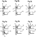
- the Auslösschräge necessary for this can, as in the 8 and 9 can be seen, in each case either be arranged on the latching projection 8 and / or the associated locking groove 4.
- These figures each show schematically with reference to a longitudinal section of the door spar 2 with a content Erten, upper door rack 51 and a lower door rack 52. In each case, the lower door rack 52 is in its holding position in which the latching connection firmly closed.
- the upper door rack 51 is illustrated in each case in an adjustment position in which it is raised and in which the latching connection, due to the interaction of the two latching elements - locking projection and latching groove - of which in each case at least one has a Auslbücherschräge 18, is solved.
- Fig. 8a shows an example in which arranged on the spring element of the respective side wall of the door compartment 51 and 52 locking projection 8 has a Auslbücherschräge 18 which slides along the upper edge of the locking groove 4 as soon as the door rack 51 or 52 is lifted up.
- the latching projection 8 is pushed away from the door handle 2 into the interior of the door compartment 51, thus releasing the latching connection.
- the door rack 51 removed by a movement upward from the locking grooves 4 of the door Holmes 2, ie a freewheel for the door rack 51 are provided and this are pushed up until the locking projection 8 hooks in the next existing locking groove 4.
- Fig. 8b is another embodiment to see in which the Ausletteschräge 18 is integrally formed on the upper side of the locking groove 4.
- the locking groove 4 is thus not as in the Fig. 8a rectangular, but it runs diagonally upwards.
- the detent projection 8 on the triggering slope formed by the upper portion of the detent protrusion 8 can be slidably pushed toward the inside of the door compartment 51 while sliding along the trimming slope 18.
- the locking connection is also released when Nachobenbe admire the door compartment 51.
- the door racks can therefore be adjusted by one hand.
- Fig. 8c shows a further example in which both in the locking groove 4 and in the locking projection 8 a release bevel is provided.
- the respective latching projection 8 and the associated latching groove 4 are further designed such that the door rack 5 is blocked or blocked in a downward movement when its spring elements are at rest and not actively pressed by applied external pressure by hand into the interior of the door compartment.
- the respective latching projection 8 sits on its horizontally extending lower edge on a preferably horizontally arranged support zone in the lower edge region of the locking groove assigned to it. It is there so formed a kind of undercut between latching projection and locking groove.
- both locking elements are formed as projections. If the latching connection is closed, that is, the door rack is held, the lower surface of the latching projection 8 lies, as in FIG Fig. 9a can be seen on the lower door rack 52, on the flat surface of the latching projection 41st on Mosholm 2 on. Both contact surfaces are aligned horizontally, as well as in all other examples, such as the FIGS. 8a-8c , you can see.
- the passing with the lower edge of the projection 41 in contact surface of the locking projection 8 is formed as a triggering slope, that is, it is tilted in the direction of displacement.
- a locking connection with the same functionality can be achieved by the projection 41 is provided on the door spar 2 with a Auslbücherschräge 18 on its underside, so that the rectangular projection formed in this case locking projection when Nachobenbe admire the door rack 51 slides on this Auslbücherschräge 18 and also inwards is pressed, the way for the door rack is free. Also on the same principle, but a bit easier to operate, that is in the Fig. 9c shown pair of locking projections 8 and 41, in which each projection has a Auslbücherschräge 18 which come to rest when the door rack 51 is moved upward.
- the Auslenseschräge 18 of the locking projection 41 is in turn on the underside, while the Auslettesschräge 18 is located on the locking projection 8 of the spring element of the door compartment 51 on the upper side.
- the two Auslenseschrägen 18 preferably have the same orientation in this case, so that they come to lie parallel to each other and the locking projection 8 can slide well over the locking projection 41 away during an upward movement of the door compartment.
- each of the two side walls of the respective Door compartment provided at least one spring element which forms part of the lateral outer wall of the door compartment.
- the spring element is integrated in the side wall largely flush.
- it may preferably be cut free from the plastic material of the side wall such that its free end can be deflected transversely or laterally out of the positional plane of the side wall, which runs essentially orthogonal to the plane-shaped inner wall of the refrigerator door.
- At least one locking cam or other locking element is provided at the freely deflectable end of the spring element.
- This locking cam engages in the undeflected resting state of the spring element in an associated counterpart on the door spar, in particular a locking groove of a plurality of arranged in different height positions a locking grooves, which are provided on the inner, substantially orthogonal to the plane-shaped inner wall of the refrigerator door extending inside the door spar.
- the spring element in the respective side wall of the door compartment may expediently be cut free by slitting in such a way that, for its freely deflectable end in the region of its articulation foot, a turning or bending axis results, which runs essentially in the vertical height direction.
- the spring element extends in this case preferably in the depth direction of the respective side wall of the door compartment. In particular, it is formed with respect to its outer contour strip-shaped or narrow rectangular.
- the spring element is preferably provided further back in the side wall than the free cut end of the spring element.
- the fixed Anschfuß of the spring element in the rear edge zone region of the side wall ie formed in the region near the back wall of this side wall of the door compartment.
- the Anlenkfuß, ie provide the material connection of the spring element on the rear wall of the door compartment.
- the cut-away portion of the spring member preferably extends around the rear corner from the rear wall to the side wall as a right-angled outer wall piece.
- the Anlenkfuß then sits further forward in the side wall, while the free end of the spring element is located further back.
- the spring element in the respective side wall of the door compartment can also be cut free such that, for its freely deflectable end in the region of its fixed Auslenkfußes a rotational or bending axis results, which extends substantially in the horizontal direction. In particular, it extends in the vertical direction, d. H. from top to bottom or vice versa.
- a rotational or bending axis results, which extends substantially in the horizontal direction. In particular, it extends in the vertical direction, d. H. from top to bottom or vice versa.
- the spring element may be provided in the region of the bottom of the door compartment in the rear corner region and extend the laterally freely deflectable end of the spring element vertically upwards to the upper edge of the side wall of the door compartment.
- the spring element may optionally be provided in the bottom part of the door compartment in an analogous manner.
- its cut-free section extends into the rear wall of the door compartment, while its articulation foot is arranged in the bottom part of the door compartment. It may be advantageous if such a spring element is cut free in the ground, in particular in the edge zone of the respective side wall of the door compartment.
- the side walls, the bottom and the rear wall of the door compartment made of the same plastic material (in particular in so-called 1K (one-component) - spraying) are made and the respective spring element is cut or cut out of this uniform, single material.
- the region of the respective side wall, the bottom and / or the rear wall, from which the spring element is cut out is made of a more elastic, flexible plastic material than the remaining part of the door compartment. This can be ensured in particular by so-called 2K (two-component) or multi-component injection molding in production.
- a cut-free spring element it may also be expedient to subsequently insert a leaf-spring-like spring element in a recess or gap of at least one wall part of the door compartment, in particular its side wall, in such a way that that this inserted spring element largely closes this gap and forms a partial surface of the outer wall of the door compartment.
- this inserted spring element closes or covers the gap or recess largely flush with the wall parts surrounding it.
- a subsequently used, separate spring element may be used for this particular, a metallic material.
- the spring element z. B. as a metal spring, preferably metallic leaf spring may be formed.
- the door compartment is thus composed of two parts.
- the respective spring element forms a component of at least one wall of the door compartment and is arranged therewith substantially in the same positional plane, and cooperates with latching means on the refrigerator door. Then results for the door racks a largely closed, smooth outer surface and inner surface.
- the respective spring element is fitted into the wall gap of the respective wall in such a way that it largely complements and fills it completely. In particular, it is largely flush with the respective wall in which it is provided.
- its thickness corresponds substantially to the thickness of the wall in which it is molded or clipped.
- the outer surface of the spring element is then preferably at the same lateral height as the wall surfaces of which it is surrounded. In particular, it may expediently be formed like a leaf spring.
- at least one spring element is arranged on the surface of at least one wall, in particular on the surface of each side wall, the rear wall, and / or the bottom of the door compartment.
- the respective spring element forms a surface component of at least one wall of the door compartment in its positional plane. It has at its deflectable end portion one or more latching means, in particular latching cams which cooperate with one or more latching means, in particular latching grooves on the door, in particular the respective Mosholm.
- the latching or latching connection between the respective latching cam at the resilient end of the spring element and the corresponding latching groove on the door, in particular the inside of the door spar is in particular designed such that when a sliding movement of the door compartment in the height direction upwards its freewheel is ensured and on the Walk of the Door cabinet down a blockage or running lock is effected.
- the locking cam in the region of its upper edge or the locking groove is provided in its upper edge region with a tripping slope.
- This tripping slope runs, preferably at an acute angle, towards the vertical upward movement direction of the respective side wall of the door compartment.
- the tripping bevels on the respective locking cam in the region of the upper edge or the upper half of the locking groove helps the locking cam on the spring element to a sliding movement such that these laterally when moving the door compartment laterally or transversely to the rest position plane of the spring element with this pushed into the interior of the door compartment is until finally the locking knob is moved out of the locking groove and the path is released for the door rack.
- the respective latching groove on the door spar and the latching knob on the spring element form a tilting or undercut in their lower contact area.
- the latching nub at its lower edge and the latching groove at its lower bearing edge have a substantially horizontal bearing surface.
- the latching nub on the respective spring element thus preferably rests with a substantially horizontal plane-like seating surface on the horizontal planar-faced inner edge of the respective assigned latching groove on the door spar.
- latching projections are provided on the respective door spar instead of locking grooves
- a triggering slope in the lower region of the respective latching projection of the respective door spar and / or in the upper region of the respective latching projection on the spring element of the door compartment for a freewheeling up is expedient in an analogous manner.
- the respective latching projection on the door spar in its upper region and / or the respective latching projection on the spring element of the door compartment in its lower region a horizontally extending support surface, which leads to a tilting of the latching projections when contacting.
- other geometry forms are possible, which allow an automatic locking in a downward movement of the door compartment.
Landscapes
- Engineering & Computer Science (AREA)
- Chemical & Material Sciences (AREA)
- Combustion & Propulsion (AREA)
- Physics & Mathematics (AREA)
- Mechanical Engineering (AREA)
- Thermal Sciences (AREA)
- General Engineering & Computer Science (AREA)
- Refrigerator Housings (AREA)
Description
Die Erfindung betrifft ein Kältegerät, insbesondere Haushalts-Kältegerät, mit mindestens einem an der Innenwand seiner Kältegerätetür höhenverstellbar angeordneten Türabsteller.The invention relates to a refrigeration device, in particular household refrigerating appliance, with at least one door racks arranged height-adjustable on the inner wall of its refrigerator door.
Kältegeräte, insbesondere Haushalts-Kältegeräte wie z. B. Kühlschränke, Gefrierschränke oder Kühl-/Gefrierkombinationsgeräte, weisen üblicherweise ein oder mehrere Türabsteller, also Ablagefächer oder Ablagebehälter für Kühlgut wie z. B. Flaschen, Getränkepackungen, Eier, Butterbehälter oder andere kleinere Kühlgüter auf. Diese sind bei einfachen Kältegerätetypen dauerhaft in einer bestimmten, fest vorgegebenen Höhenposition an der Innenwand der Kältegerätetür fest montiert. Bei Haushalts-Kältegerätetypen mit besserer Ausstattung ist der jeweilige Türabsteller lösbar an der Tür der Kältegeräte befestigt und kann bezüglich seiner Höhenposition versetzt werden, so dass die Einteilung der Türabsteller an der Kältegerättür unterschiedlichen Größenverhältnissen von einzulagerndem Kühlgut angepasst werden kann. Zumeist sind für den jeweiligen Türabsteller an der Türinnenwand des Kältegeräts Haltenocken in zwei verschiedenen, fest vorgegebenen Befestigungspositionen vorgesehen. Zum Wechsel der Höhenposition des jeweiligen Türabstellers ist es bisher erforderlich, dass dieser von den Haltenocken an der Türinnenwand aus seiner bisherigen Montageposition komplett abgenommen und dann in der neuen Höhenposition mit dort an der Türinnenwand vorgesehenen Haltenocken fest verrastet wird. Dies ist recht umständlich, unbequem und aufwendig. Insbesondere ist es in der Regel notwendig, dass ein derartiger Türabsteller vor dem Verstellen leer geräumt wird. Üblicherweise sind pro Türabsteller lediglich zwei verschiedene, fest vorgegebene Höhenlagen vorgesehen, woraus sich eine geringe Flexibilität in der Anordnung der Türabsteller ergibt.Refrigerators, especially household refrigerators such. As refrigerators, freezers or refrigerator / freezer combination devices, usually have one or more door racks, so storage compartments or storage containers for refrigerated goods such. As bottles, beverage packs, eggs, butter containers or other smaller refrigerated goods. These are permanently mounted in simple, refrigeration unit types permanently in a certain, fixed predetermined height position on the inner wall of the refrigerator door. In household refrigeration appliance types with better features of the respective door rack is releasably attached to the door of the refrigerators and can be offset with respect to its height position, so that the classification of door racks on the refrigerator door different size ratios can be adjusted by einzulagerndem refrigerated goods. In most cases, retaining cams are provided in two different, fixed predetermined fastening positions for the respective door racks on the door inner wall of the refrigerator. To change the height position of the respective door compartment, it has been required that this is completely removed from the retaining cams on the inner wall of the door from its previous mounting position and then firmly locked in the new height position with there provided on the inner door wall retaining cams. This is quite complicated, inconvenient and expensive. In particular, it is usually necessary that such a door rack is cleared before adjusting empty. Usually only two different, fixed predetermined altitudes are provided per door rack, resulting in a low flexibility in the arrangement of the door racks.
Oftmals ist es jedoch wünschenswert, eine feinere, auf unterschiedlich hohe Verpackungshüllen des einzulagernden Kühlguts eingehende Positioniermöglichkeit der Türabsteller vorzusehen. In der
Die Offenlegungsschrift
Die Patentschrift
Die Gebrauchsmusterschrift
Der Erfindung liegt die Aufgabe zugrunde, ein Kältegerät, insbesondere Haushalts-Kältegerät, mit ein oder mehreren Türabstellern an der Innenwand dessen Kältegerätetür bereitzustellen, für die eine feine Höhenverstellung konstruktiv einfach, bequem bedienbar und zuverlässig möglich ist.The invention has for its object to provide a refrigerator, in particular household refrigeration appliance, with one or more door cabinets on the inner wall of the refrigerator door for which a fine height adjustment is structurally simple, easy to use and reliable possible.
Die Aufgabe wird durch die Merkmale des unabhängigen Anspruch 1 gelöst. Bevorzugte Ausführungsformen sind Gegenstand der abhängigen Ansprüche.The object is solved by the features of independent claim 1. Preferred embodiments are subject of the dependent claims.
Insbesondere wird diese Aufgabe bei einem Kältegerät, insbesondere Haushalts-Kältegerät der eingangs genannten Art, dadurch gelöst, dass mindestens eine Wand des Türabstellers zu dessen Höhenverstellung als Bestandteil mindestens ein Federelement aufweist, das quer, insbesondere senkrecht zur Lageebene der Wand federelastisch auslenkbar ist. Dadurch ist eine einfache Grundgeometrieform des jeweiligen Türabstellers sichergestellt, der durch mindestens ein Federelement, das seitlich bzw. lateral bezüglich der Lageebene mindestens einer Wand des Türabstellers als deren Bestandteil auslenkbar ist, gleichzeitig eine einfache und bequeme Höhenverstellung erlaubt. Da das Federelement Bestandteil der Wand ist, ist in vorteilhafter Weise eine weitgehend geschlossene Außen- und/oder Innenoberfläche der Wand ermöglicht. Dadurch, dass das jeweilige Federelement, das insbesondere mindestens ein Rastele ment an der Außenseite seines frei auslenkbaren Endes zum Verrasten des Türabstellers mit der Innenwand der Kältegerätetür aufweist, Bestandteil mindestens einer Wand des Türabstellers ist, ist es möglich, die ursprüngliche Geometrieform der jeweiligen Wand des Türabstellers trotz Aufnahme des jeweiligen Federelements als zusätzliche Funktionskomponente weitgehend beizubehalten, d.h. es ergibt sich eine weitgehend einheitliche, insbesondere in sich geschlossene Geometrieform des Türabstellers bei gleichzeitiger Integration von ein oder mehreren Federelementen in ein oder mehreren Wänden. Es ist somit weitgehend vermieden, dass die jeweilige Wand des Türabstellers unzulässige große Lücken oder Durchbrüche oder seitliche, lateral nach außen oder innen hervorstehende Vorsprünge in Form von Rastlagern oder dergleichen aufweist. Das zusätzliche Federelement ist vorzugsweise derart als Bestandteil der Wand in diese integriert oder an diese angeformt, dass eine lokale, unerwünscht große Wandaufdickung weitgehend vermieden ist. Auf diese Weise kann der Türabsteller insbesondere mit einer weitgehend in sich geschlossenen, vorzugsweise etwa rechteckförmigen Kastenform ausgebildet sein. Durch die weitgehend geschlossenen Oberflächen seiner beiden Seitenwände, seiner Rückwand und seines Bodens ist er leicht reinigbar und gegen das Festsetzen von Schmutz- und Staubpartikeln weitgehend unempfindlich. Auch sind Fehlbetätigungen des Türabstellers bei dessen Höhenverstellung weitgehend vermieden, da das Eindringen von Teilen von Kühlgütern zwischen Federelement und Wand weitgehend vermieden ist. Gleichzeitig bildet das Federelement als Wandbestandteil in oder an der jeweiligen Wand des Türabstellers eine einfache, bequem bedienbare und zuverlässige konstruktive Möglichkeit, den Türabsteller mit der Innenwand der Kältegerätetür in verschiedenen Höhenpositionen zu verrasten. Durch drücken des jeweiligen Federelements lässt sich dieses, insbesondere dessen jeweiliges, außenseitig angebrachtes Rastelement, aus seiner Verrastung mit der Innenwand der Tür lösen. Ein derartiges Türabstellerrastsystem ist dabei einfach zu bedienen und die Rastfunktion des jeweiligen Federelements selbsterklärend. Insbesondere ist es somit nicht erforderlich, einen zusätzlichen Druckknopf oder eine zusätzliche Drucktaste am Türabsteller zum manuellen Auslösen des jeweiligen Federelements vorzusehen.In particular, this object is achieved in a refrigeration appliance, in particular domestic refrigeration appliance of the type mentioned, that at least one wall of the door compartment to its height adjustment as part of at least one spring element which is transversely, in particular perpendicular to the plane of the wall resiliently deflectable. This ensures a simple basic geometry shape of the respective door compartment, which at the same time permits a simple and convenient height adjustment by means of at least one spring element, which is laterally or laterally deflectable with respect to the positional plane of at least one wall of the door compartment as its component. Since the spring element is part of the wall, a largely closed outer and / or inner surface of the wall is made possible in an advantageous manner. Characterized in that the respective spring element, in particular at least one Rastele ment on the outside of his freely deflectable end for locking the door compartment with the inner wall of the refrigerator door is part of at least one wall of the door compartment, it is possible to largely maintain the original geometry of the respective wall of the door compartment despite receiving the respective spring element as an additional functional component, ie there is a largely uniform, especially self-contained geometry of the door compartment with simultaneous integration of one or more spring elements in one or more walls. It is thus largely avoided that the respective wall of the door compartment has impermissible large gaps or openings or lateral, laterally outwardly or inwardly projecting projections in the form of latching bearings or the like. The additional spring element is preferably integrated as part of the wall in this or formed on this, that a local, undesirably large wall thickening is largely avoided. In this way, the door rack can be formed in particular with a largely self-contained, preferably approximately rectangular box shape. Due to the largely closed surfaces of its two side walls, its back wall and its bottom, it is easy to clean and largely insensitive to the setting of dirt and dust particles. Also incorrect operation of the door compartment at the height adjustment are largely avoided, since the penetration of parts of refrigerated goods between spring element and wall is largely avoided. At the same time, the spring element forms a wall component in or on the respective wall of the door compartment a simple, easy to use and reliable constructive way to lock the door compartment with the inner wall of the refrigerator door in different height positions. By pressing the respective spring element can this, in particular its respective, externally mounted latching element, release from its latching with the inner wall of the door. Such Türabstellerrastsystem is easy to use and the locking function of each spring element self-explanatory. In particular, it is thus not necessary to provide an additional push button or an additional pushbutton on the door racks for manual release of the respective spring element.
Nach einer zweckmäßigen Weiterbildung der Erfindung ist die Höhenverstellung des jeweiligen Türabstellers über eine Rastverbindung realisiert, bei der jeweils mindestens ein am Türabsteller angeordnetes Rastelement in ein dazu korrespondierend geformtes Halteelement wie z.B. eine Rastnut aus einer Vielzahl von Rastelementen an der Kältegerätetür, die vorzugsweise beidseitig an den Türholmen vorgesehen sind, eingreift. Dabei ist insbesondere mindestens ein Rastelement an der Außenseite mindestens eines Federelements angeordnet, welches Bestandteil mindestens einer Wand, vorzugsweise der jeweiligen Seitenwand, ggf. zusätzlich oder unabhängig hiervon insbesondere auch des Bodens und/oder der Rückwand des Türabstellers ist. Das Federelement kann direkt durch Druck vorzugsweise nach Innen quer bzw. lateral zur Seitenwand, Rückwand und/oder Boden des Türabstellers ausgelenkt und dabei sein Rastelement aus einem jeweils korrespondierend zugeordneten Halteelement der Kältegerätetür gelöst werden.After an expedient development of the invention, the height adjustment of the respective door compartment is realized via a latching connection, in each case at least one locking element arranged on the door racks in a correspondingly shaped retaining element such as a locking groove of a plurality of locking elements on the refrigerator door, which are preferably provided on both sides of the door beams, engages. In this case, in particular at least one latching element is arranged on the outside of at least one spring element which is part of at least one wall, preferably the respective side wall, optionally additionally or independently thereof, in particular also of the bottom and / or the rear wall of the door compartment. The spring element can be deflected directly by pressure preferably inward transversely or laterally to the side wall, rear wall and / or bottom of the door compartment and thereby be released locking element from a corresponding respectively associated holding element of the refrigerator door.
Dadurch, dass nach einer besonders vorteilhafter Ausführungsvariante der Erfindung das Federelement eine Teilfläche, insbesondere Oberfläche der jeweiligen Seitenwand, des Bodens und/oder der Rückenwand des Türabstellers bildet, ist eine im Wesentlichen in sich geschlossene Außenoberfläche und/oder Innenoberfläche für die jeweilige Seitenwand, Rückwand und/oder den Boden des Türabstellers sichergestellt. Indem das jeweilige Federelement als Bestandteil der jeweiligen Seitenwand, des Bodens, und/oder der Rückenwand des Türabstellers vorgesehen ist, ist darüber hinaus ein Eindringen von Schmutz zwischen dem Federelement und der Seitenwand, dem Federelement und/oder Rückenwand und/oder dem Federelement und dem Boden weitgehend vermieden. Es lässt sich dadurch insbesondere eine weitgehend glatte, durchgängige Außenoberfläche und/oder Innenoberfläche des jeweiligen Türabstellers bereitstellen, die reinigungsfreundlich ist. Darüber hinaus ist der Türabsteller dadurch mit einer einheitlichen, ästhetisch ansprechenden Geometrieform ausbildbar, die von keiner zu großen, flächigen Aussparung bzw. keinem zu großem, flächigen Durchbruch unterbrochen ist.The fact that, according to a particularly advantageous embodiment of the invention, the spring element forms a partial surface, in particular surface of the respective side wall, the bottom and / or the back wall of the door compartment is a substantially self-contained outer surface and / or inner surface for the respective side wall, rear wall and / or ensured the bottom of the door compartment. By the respective spring element is provided as part of the respective side wall, the bottom, and / or the back wall of the door compartment, moreover, an ingress of dirt between the spring element and the side wall, the spring element and / or back wall and / or the spring element and the Soil largely avoided. This makes it possible to provide in particular a largely smooth, continuous outer surface and / or inner surface of the respective door compartment, which is easy to clean. In addition, the door rack is thereby formed with a uniform, aesthetically pleasing geometry shape, which is interrupted by no too large, areal recess or no large, areal breakthrough.
In einer bevorzugten Ausführungsform ist das Federelement in seiner Ruheposition weitgehend flächenbündig in die Seitenwand, Rückwand, und/oder den Boden des Türabstellers integriert und/oder an diese angeformt, d.h. das Federelement in oder an der jeweiligen Seitenwand, Rückwand und/oder dem Boden bildet zusammen mit der jeweiligen Seitenwand, Rückwand und/oder dem Boden eine weitgehend einheitliche Oberfläche, welche nur durch sehr schmale Durchbruchslinien unterbrochen ist, über die das federnde Ende des Federelements von der Seitenwand, Rückwand und/oder dem Boden getrennt ist, so dass es quer zu dieser und/oder diesem auslenkbar ist. Dadurch bleibt trotz ein oder mehrerer Federelemente die glatte Oberfläche des Türabstellers außen und/oder innen erhalten. Sie kann einfach gereinigt werden und wird optisch nicht beeinträchtigt.In a preferred embodiment, the spring element in its rest position is largely flush-integrated in the side wall, rear wall, and / or the bottom of the door compartment and / or formed on this, that forms the spring element in or on the respective side wall, rear wall and / or the bottom together with the respective side wall, rear wall and / or the bottom a substantially uniform surface, which is interrupted only by very narrow breakthrough lines over which the resilient end of the spring element from the side wall, rear wall and / or the bottom is separated, so that it transversely is deflected to this and / or this. This remains despite a or more spring elements receive the smooth surface of the door compartment outside and / or inside. It can be easily cleaned and visually unaffected.
Gemäß einer weiteren zweckmäßigen Weiterbildung kann die Fläche des Federelements ebenso wie die Fläche der jeweiligen Seitenwand des Türabstellers an einem Abschnitt ihrer Tiefenerstreckung eine nach innen geformte Stufe aufweisen, d. h. die jeweilige Seitenwand und ihr Federelement formen zusammen eine in Höhenrichtung vertikal verlaufende Führungsnut bzw. Führungsrille, die eine Führungsleiste bspw. eines Türholmes an der Innenwand der Kältegerätetür formschlüssig aufnehmen kann und so eine Verkippsicherung für den Türabsteller bildet, wenn dieser im gelösten Zustand höhenverschoben wird.According to a further expedient development, the surface of the spring element as well as the surface of the respective side wall of the door compartment at a portion of its depth extension may have an inwardly formed step, d. H. the respective side wall and its spring element together form a vertically extending in the vertical direction guide groove or guide groove, which can receive a guide rail, for example. A door Holmes on the inner wall of the refrigerator door form fit and forms a Verkippsicherung for the door racks, if this is moved vertically in the released state.
In einer weiteren, besonders vorteilhaften Ausführungsform kann das jeweilige Federelement vorzugsweise in die Seitenwand, in die Rückwand, und/oder in den Boden des Türabstellers dadurch integriert sein, dass es aus deren Wandmaterial frei geschnitten ist. Dadurch kann es extrem einfach einteilig mit der Seitenwand, der Rückwand und/oder dem Boden hergestellt werden. Als Durchbrüche treten nur die sehr schmalen Freischnittlinien auf und das Federelement ist automatisch flächenbündig mit der Seitenwand, der Rückwand, und/oder dem Boden ausgebildet. Dadurch lässt sich der Produktionsprozess für den Türabsteller mit integrierter Höhenverrastung erheblich vereinfachen.In a further, particularly advantageous embodiment, the respective spring element can preferably be integrated in the side wall, in the rear wall, and / or in the bottom of the door compartment in that it is cut free from its wall material. This makes it extremely easy to make one-piece with the side wall, the rear wall and / or the floor. As breakthroughs occur only the very narrow cut-free lines and the spring element is automatically formed flush with the side wall, the rear wall, and / or the bottom. This considerably simplifies the production process for the door racks with integrated height lock.
In einer besonders bevorzugten Ausführungsform ist das Federelement an die jeweilige Seitenwand angelenkt, also an seinem ortsfesten Anlenkende fest mit der Seitenwand verbunden. Insbesondere ist das Federelement derart an die Seitenwand angelenkt, dass es bezüglich einer in Höhenrichtung des Türabstellers vertikal verlaufenden Biegeachse quer bzw. lateral bezogen auf die Lageebene der Seitenwand auslenkbar ist. Bevorzugt ist es einteilig mit der Seitenwand hergestellt und aus dieser bis auf seinen Anlenkfuß frei geschnitten. Es kann jedoch auch an diese angeformt wie bspw. angespritzt sein. Indem es direkt an die jeweilige Seitenwand angeformt ist, kann es einfach ohne weitere Verbindungen oder Montageschritte realisiert werden. In entsprechender Weise kann es zusätzlich oder unabhängig hiervon auch an der Rückwand und/oder den Boden des jeweiligen Türabstellers angeformt sein.In a particularly preferred embodiment, the spring element is articulated to the respective side wall, that is fixedly connected to the side wall at its stationary articulation end. In particular, the spring element is articulated to the side wall in such a way that it can be deflected transversely or laterally relative to the positional plane of the side wall with respect to a bending axis running vertically in the vertical direction of the door compartment. Preferably, it is made in one piece with the side wall and cut out of it to its Anlenkfuß. However, it can also be molded on these as, for example, be sprayed. By being molded directly to the respective side wall, it can be easily realized without further connections or assembly steps. In a corresponding manner, it may be additionally or independently thereof also formed on the rear wall and / or the bottom of the respective door compartment.
Zweckmäßigerweise wird für das Federelement ein elastischeres Kunststoffmaterial als für die Seitenwand, Rückwand und/oder den Boden des Türabstellers verwenden, welches zwar genügend Spannung aufbringt, um das Rastelement in seiner Halteposition zu halten, aber gleichzeitig gut auslenkbar ist. Darüber hinaus kann es vorzugsweise farblich oder durch die Materialwahl von der jeweiligen Seitenwand, der Rückwand und/oder dem Boden abgesetzt sein, um seine Funktionalität sofort kenntlich zu machen.Appropriately, for the spring element, a more elastic plastic material than for the side wall, rear wall and / or the bottom of the door compartment use, which indeed applies enough tension to hold the locking element in its holding position, but at the same time is well deflected. In addition, it may preferably be colored or by the choice of material of the respective side wall, the rear wall and / or the bottom discontinued to make its functionality immediately identified.
In einer weiteren bevorzugten Ausführungsform kann das angelenkte, d.h. fest angebrachte Ende des Federelements mit der Rückwand des Türabstellers verbunden sein. Dadurch kann der von Außen sichtbare Bereich des Federelements, welcher als Druckbereich dient und sich vorzugsweise vor einer Führungsleiste des Türholmes befindet, deutlich kürzer als bei einer Anlenkung an einer Längsstelle der Tiefenerstreckung der jeweiligen Seitenwand gehalten werden.In a further preferred embodiment, the hinged, i. firmly attached end of the spring element to be connected to the rear wall of the door compartment. As a result, the visible from the outside region of the spring element, which serves as a pressure area and is preferably located in front of a guide rail of the door Holmes, significantly shorter than an articulation at a longitudinal point of the depth extension of the respective side wall.
In einer weiteren vorteilhaften Ausführungsform weist die jeweilige Seitenwand des Türabstellers entlang einer Teillänge oder ihrer Gesamtlänge eine in vorgegebenem Querabstand zu dieser verlaufende Innenwand auf, wobei der Abstand zwischen diesen beiden Wänden, d.h. der Außen- und Innenwand, der doppelwandigen Seitenwand so gewählt ist, dass er im Wesentlichen dem Auslenkbereich des Federelements entspricht. Das Federelement bewegt sich also zwischen den beiden Wänden der Seitenwand. Dadurch ist das Federelement besser vor Kühlgut abgeschirmt. Die Innenseite des Türabstellers bildet dabei vorzugsweise eine geschlossene Oberfläche, die einfach zu reinigen ist.In a further advantageous embodiment, the respective side wall of the door compartment along a partial length or its entire length at a predetermined transverse distance extending to this inner wall, wherein the distance between these two walls, i. the outer and inner walls, the double-walled side wall is selected so that it substantially corresponds to the deflection of the spring element. The spring element thus moves between the two walls of the side wall. As a result, the spring element is better shielded from refrigerated goods. The inside of the door compartment preferably forms a closed surface, which is easy to clean.
In einer weiteren vorteilhaften Ausführungsform kann das Federelement an die Unterkante der jeweiligen Seitenwand und/oder Rückwand des Türabstellers angeformt sein und vorzugsweise eine mit der Seitenwand und/oder Rückwand flächenbündige Verlängerung bilden. Dadurch ist es nicht erforderlich, die Seitenwand und/oder Rückwand einzuschneiden. Der Türabsteller behält seine einfach zu reinigende, geschlossene Innenfläche. Das Federelement kann hier insbesondere sowohl an die Seitenwand als auch an die Seitenwand angeformt bzw. angelenkt sein.In a further advantageous embodiment, the spring element can be integrally formed on the lower edge of the respective side wall and / or rear wall of the door compartment and preferably form a flush with the side wall and / or rear wall extension. As a result, it is not necessary to cut in the side wall and / or rear wall. The door rack retains its easy-to-clean, closed interior surface. The spring element can in particular be integrally formed or articulated both on the side wall and on the side wall.
In einer weiteren bevorzugten Ausführungsform kann das Federelement an den oberen Bereich der Seitenwand des Türabstellers angeformt sein und vertikal nach unten hin frei federn. Dadurch ist es entlang einer in Tiefenrichtung des Türabstellers verlaufenden Biegeachse seitlich bzw. lateral aus der Lageebene der Seitenwand des Türabstellers auslenkbar. Dadurch kann sein federndes Ende, ohne den Benutzer zu stören, nach unten hin verlängert sein. Dies ergibt einen längeren Hebel zum Öffnen der Rastverbindung und vereinfacht damit das Lösen des Türabstellers.In a further preferred embodiment, the spring element can be integrally formed on the upper region of the side wall of the door compartment and spring freely downwards. As a result, it can be deflected laterally or laterally out of the plane of the side wall of the door compartment along a bending axis extending in the depth direction of the door compartment. As a result, its resilient end, without disturbing the user, be extended downwards. This results in a longer lever for opening the locking connection and thus simplifies the release of the door compartment.
In einer weiteren vorteilhaften Ausführungsform weist das Rastelement des jeweiligen Federelements, das Halteelement der Kältegerätetür oder beide eine Auslöseschräge auf. Diese ist jeweils an der Oberseite des Rastelements und/oder des Halteelements angeordnet, so dass Rastelement und Halteelement bei einer Bewegung des Türabstellers nach oben aneinander vorbei im Wesentlichen freilaufend gleiten können, da dabei das Rastelement aus seinem jeweiligen Halteelement herausgedrückt wird. Dadurch wird die Rastverbindung automatisch gelöst, der Türabsteller kann nach oben versetzt werden.In a further advantageous embodiment, the latching element of the respective spring element, the holding element of the refrigerator door or both on a tripping slope. This is in each case arranged on the upper side of the latching element and / or of the holding element, so that the latching element and the holding element can slide upwardly past one another substantially free-running during a movement of the door compartment, since the latching element is pushed out of its respective holding element. As a result, the latching connection is automatically released, the door rack can be moved upwards.
Gemäß einer weiteren zweckmäßigen Weiterbildung der Erfindung liegen das Rastelement des jeweiligen Federelements und das zugehörige Halteelement an ihrer jeweiligen Unterseite entlang vorzugsweise horizontaler Kontaktzonen derart aneinander, dass in Abwärtsrichtung eine gegenseitige Verrastung bzw. Sperre resultiert.According to a further expedient development of the invention, the latching element of the respective spring element and the associated holding element lie against one another at their respective underside, preferably along horizontal contact zones, such that a mutual latching or blocking results in the downward direction.
Sonstige Weiterbildungen der Erfindung sind in den Unteransprüchen wiedergegeben.Other developments of the invention are given in the dependent claims.
Die Erfindung und ihre Weiterbildungen werden nachfolgend anhand von Zeichnungen näher erläutert.The invention and its developments are explained in more detail with reference to drawings.
Es zeigen jeweils schematisch:
- Fig. 1
- in perspektivischer Darstellung einen Ausschnitt aus der Tür eines Haushalts-Kältegeräts, insbesondere Haushalts-Kühlschranks, mit einem höhenverstellbaren Türabsteller, der nach einer ersten Ausführungsvariante des erfindungsgemäßen Konstruktionsprinzips ausgebildet ist,
- Fig. 2
- schematisch in perspektivischer Darstellung einen Ausschnitt der Tür von
Figur 1 mit ihrem Türabsteller bei dessen Entnahme bei Blickrichtung von oben, - Fig. 3
- einen schematischen Schnitt durch einen Teil der Kältegerätetür zusammen mit dem Türabsteller von
Figur 1 im Bereich des Federelements dessen von vorne betrachtet linken Seitenwand, - Fig. 4a mit 4c
- schematisch verschiedene Ansichten einer zweiten vorteilhaften Variante eines erfindungsgemäß ausgebildeten Türabstellers mit lösbarem Federelement,
- Fig. 5, 6 und 7
- weitere Ausführungsbeispiele eines erfindungsgemäß ausgebildeten Türabstellers, und
- Fig. 8 und 9
- schematische Schnittdarstellungen verschiedener vorteilhafter Ausführungsvarianten von Rastverbindungen zwischen der Tür des HaushaltsKältegeräts und dem jeweiligen Türabsteller gemäß den Ausführungsbeispielen der
Figuren 1 mit 7 zu dessen Höhenverstellung.
- Fig. 1
- in a perspective view a detail of the door of a household refrigerating appliance, in particular household refrigerator, with a height-adjustable door racks, which is designed according to a first embodiment of the construction principle according to the invention,
- Fig. 2
- schematically a perspective view of a section of the door of
FIG. 1 with its door racks when it is removed when viewed from above, - Fig. 3
- a schematic section through a part of the refrigerator door together with the door rack of
FIG. 1 in the region of the spring element of the left side wall viewed from the front, - Fig. 4a with 4c
- 3 schematically different views of a second advantageous variant of an inventively designed door compartment with a releasable spring element,
- FIGS. 5, 6 and 7
- Further embodiments of an inventively designed door compartment, and
- 8 and 9
- Schematic sectional views of various advantageous embodiments of locking connections between the door of the domestic refrigeration appliance and the respective door rack according to the embodiments of the
FIGS. 1 with 7 to its height adjustment.
Elemente mit gleicher Funktion und Wirkungsweise sind in den
Der Türabsteller 5 weist in seiner dem ersten bzw. von vorne betrachtet linken Holm 2 zugeordneten Seitenwand 6 ein blattfederartiges Federelement 7 auf. Dieses trägt an seinem frei auslenkbaren Ende außenseitig einen in der Ansicht von
Das Federelement 7, welches die Rastverbindung mit den Rastnuten 4 eingeht, ist an der Seitenwand 6 des Türabstellers 5 angelenkt. In diesem Ausführungsbeispiel ist das Federelement 7 integraler Bestandteil der lateralen Seitenwand 6 des Türabstellers 5. Sein frei auslenkbares Ende ist aus der Seitenwand 6 freigeschnitten. Es ist insbesondere derart freigeschnitten, dass für seinen angelenkten, feststehenden Fuß eine vertikal verlaufende Biegeachse 75 in y-Richtung gebildet ist. Bezüglich dieser vertikalen Biegeachse 75 ist das Federelement 7 mit seinem freien Ende quer bzw. lateral, insbesondere senkrecht zur x, y Lageebene der Seitenwand 6 federelastisch beweglich auslenkbar. Das Federlement 7 ist in der Seitenwand 6 derart freigeschnitten, dass dieses streifenförmig ausgebildet ist und mit seinem oberen Rand und seinem unteren Rand im Wesentlichen parallel zur Ober- und Unterkante der Seitenwand 6 verläuft. Es ist hier im Ausführungsbeispiel im Wesentlichen im Mittenbereich der Höhenerstreckung der Seitenwand 6 angeordnet. Sein Anlenkfuß ist dabei der Vorderwand des Türabstellers 5, sein frei auslenkbares Ende hingegen der Rückwand des Türabstellers 5 zugeordnet. Wird von außen Druck auf das frei geschnittene Ende des Federelements 7 ausgeübt, und taucht dieses ins Innere des kastenförmigen Türabstellers 5 ein, so tritt der Rastvorsprung 8 an der Außenseite des freien Endabschnitts des Federelements 7 aus der Rastnut 4 im Türholm 2 heraus und der Türabsteller 5 wird zu seiner Höhenverstellung freigegeben. Der Druck von Außen auf das Federelement 7 kann entweder durch den Finger eines Benutzers erfolgen, welcher von der Außenseite der Seitenwand 6 auf den frei auslenkbaren Bereich des Federelements 7 drückt oder durch eine Auslöseschräge 9, welche in jeder Rastnut 4 und/oder am außenseitig angeordneten Rastelement des Federelements vorgesehen ist. Über diese wird der Rastvorsprung 8 in z-Richtung, also bzgl. des Türabstellers 5 ebenfalls von Außen nach Innen selbsttätig gedrückt, sobald der Türabsteller 5 nach oben, also in y-Richtung, bewegt wird. Sobald der Rastvorsprung 8 aus der Rastnut 4 gelöst ist, kann der Türabsteller 5 nach unten oder oben, also jeweils in y-Richtung, zum nächst niedrigeren oder höheren Rastvorsprung 4 bewegt werden.The
Hier im Ausführungsbeispiel bilden das Federelement 7 und die Seitenwand 6 des Türabstellers 5 zusammen im Mittenbereich der Tiefenerstreckung der Seitenwand eine vertikal verlaufende Führungsnut 10, die die vertikal verlaufende Führungsleiste 3 am dieser Sei-Seitenwand 6 zugeordneten Holm 2 der Kältegerätetür 1 aufnimmt. Dazu weist die Seitenwand 6 und das Federelement 7 in der x, z-Ebene betrachtet eine ins Innere des Türabstellers 5 ragende, im Wesentlichen rechteckförmige Stufe auf, die gegenüber der sich in Tiefenrichtung erstreckenden x,y- Lageebene der Seitenwand 6 Ins Innere des Türabstellers 5 versetzt ist. Während der Verschiebung des Türabstellers 5 in Höhenrichtung y gleitet in dieser Führungsnut 10 die Führungsleiste 3. Die Führungsleiste 3 wird dabei von der Führungsnut 10 U-förmig umklammert, d. h. von drei Seiten gefasst. Insbesondere umgreift die Führungsnut 10 die in die y, z-Ebene frei abstehende, stegartige Führungsleiste 3, die gegenüber dem ersten, in der x,y-Ebene angeordneten Türholm 2 um etwa 90° auf den anderen, zweiten Türholm zu umgebogen ist. Auf diese Weise wird der Türabsteller 5 so von der Führungsleiste 3 und gegebenenfalls der Innenwand 73 der Kältegerätetüre 1 in seiner horizontalen Position stabilisiert, wodurch ein Verkippen des Türabstellers 5 verhindert wird. Die Führungsleiste 3 verhindert auch eine vollständige Entnahme des Türabstellers 5. Die Führungsleiste 3 bzw. der Türholm 2 kann entlang der Gesamthöhenerstreckung der Kühlschranktür 1 angeordnet sein, sich also in y-Richtung entlang der gesamten Kühlschranktür 1 erstrecken. In diesem Fall ist eine Entnahme eines Türabstellers 5 nur am oberen oder unteren Ende der Kühlschranktür möglich. Um mehrere Entnahmemöglichkeiten zu ermöglichen, kann der Türholm 2 oder auch nur dessen Führungsleiste 3, alternativ abschnittsweise unterbrochen sein. Der Türabsteller 5 ist vorzugsweise aus transparentem Kunststoff geformt. Er kann aber auch im Bereich des Federelements 7 eine andere Kunststoffkomponente aufweisen, welche opak ist oder farblich oder von der Materialwahl her zum Rest des Türabstellers 5 unterschiedlich ist. Das Federelement ist aus einem Kunststoffmaterial hergestellt, das elastischer, insbesondere flexibler als das Kunststoffmaterial der übrigen Wandflächen der Seitenwand, der Rückwand und/oder Bodens ist.Here in the exemplary embodiment form the
Alternativ zum Ausführungsbeispiel kann in umgekehrter Weise im jeweiligen Türholm 2 auch eine vertikal verlaufende Führungsnut und an der zugeordneten Seitenwand des jeweiligen Türabstellers eine entsprechend in Richtung Türholm hervorstehende Führungsleiste vorgesehen sein.Alternatively to the embodiment can be provided in the opposite direction in the
Das Federelement 7 ist hier im Ausführungsbeispiel an seinem vorderen, also an dem von der Kältegerätetür 1 wegstehenden Ende an die Seitenwand 6 angelenkt. Es geht nahtlos in die Seitenwand 6 über. An seinem hinteren Ende, also an seinem der Kältegerätetür 1 zugewandten Ende, ist es in diesem Ausführungsbeispiel frei geschnitten, so dass es quer bzw. lateral, insbesondere etwa senkrecht, zur Seitenwand 6 auslenkbar ist. Die Freischnitte sind vorzugsweise so schmal wie möglich gehalten, so dass nur extrem kleine Spalte zwischen dem Federelement 7 und der Seitenwand 6 entstehen. In seiner Ruheposition ist das Federelement 7 im Wesentlichen flächenbündiger Bestandteil der weitgehend planflächigen Seitenwand 6. Trotz des eingeformten Federelements 7 hat die Seitenwand 6 bis auf ihre Führungsnut 10 damit eine im Wesentlichen plane Oberfläche, so dass sie sehr einfach zu reinigen ist. Insbesondere ist zwischen dem Federelement und dessen übrigen Teilflächen der Seitenwand kein Zwischenraum vorhanden, in dem sich Schmutz oder Bestandteile des Kühlguts festsetzen könnten, wodurch die Funktionalität der Rastverbindung des Türabstellers außer Kraft gesetzt werden könnte. Das freie federnde Ende 12 des Federelements 7 kann durch Außendruck, beispielsweise einer Hand 13 eines Benutzers, quer, insbesondere etwa senkrecht, zur Seitenwand 6 ins Innere des Türabstellers 5 ausgelenkt werden, wodurch der am freien federnden Ende 12 des Federelements 7 angebrachte, hier in den
Der für diese höhenverstellbare Befestigung speziell entwickelte Türabsteller 5 ist in den
In den
In der
Eine Variation der Ausführungsform von
Gegebenenfalls können auch Zwischenlösungen zwischen der vorherigen und der hier dargestellten Lösung zweckmäßig sein. So kann das Federelement 7 ebenfalls in dem oberen Bereich in der Seitenwand 6 hineingeschnitten sein, aber leicht über diese nach unten hinausragen. Wichtig ist immer, dass die Außenfläche der Seitenwand 6 mit der Außenfläche des Federelements 7 weitgehend bündig abschließt. Die Bewegung des Federelements 7, beispielsweise durch eine Hand 13, wie sie hier in
Für die Höhenverstellbarkeit des Türabstellers sind ggf. die Führungsnut in der jeweiligen Seitenwand des jeweiligen Türabstellers sowie der darin geführte Führungssteg am jeweiligen Türholm entbehrlich. Dann entfällt zwar die Kippsicherung gegen Verkippen nach vorne und hinten, jedoch bleibt die einfache Höhenverstellbarkeit des jeweiligen Türabstellers aufgrund mindestens eines seitlich auslenkbaren Federelements in oder an mindestens einer Wand des Türabstellers erhalten.For the height adjustment of the door compartment, if necessary, the guide groove in the respective side wall of the respective door compartment as well as the guide web guided therein on the respective door handle are dispensable. Although then the anti-tilt device against tilting forwards and backwards, but the simple height adjustment of the respective door compartment remains due to at least one laterally deflectable spring element in or on at least one wall of the door compartment.
Eine weitere Möglichkeit der Anbindung eines Federelements 7 in oder an die Seitenwand 6 eines Türabstellers 5 ist in den
Gemäß einer anderen Ausführungsform kann es ggf. zweckmäßig sein, das federnde Ende des Federelements 7 nicht vor die Führungsleiste 3 zu ziehen, sondern hinter der Führungsleiste direkt senkrecht unter dem Haltebereich 16 anschließen zu lassen. In diesem Beispiel sind das Federelement und damit der Türabsteller 5 einfacher als in dem hier dargestellten Beispiel formbar. Jedoch sind in diesem Fall zum Öffnen der Rastverbindung, also zum Nachinnendrücken des Federelements 7, zweckmäßigerweise Aussparungen oder Durchgriffsöffnungen im Türholm 2 vorgesehen, durch welche das federnde Ende des Federelements 7 erreichbar ist, um den Rastvorsprung 8 nach innen ins Innere des Türabstellers zu drücken und damit die Rastverbindung des Türabstellers 5 am Türholm zu lösen.According to another embodiment, it may be appropriate not to pull the resilient end of the
Zweckmäßig ist es in allen Varianten von Rastverbindungen, wenn mindestens eines der zusammenwirkenden Rastelemente am Türabsteller und/oder Türholm eine Auslöseschräge 18 aufweist, wie sie in der
In den in den
Alle in diesen Ausführungsbeispielen gezeigten Auslöseschrägen sind vorzugsweise eben geformt. Sie könnten jedoch ebenso gut gebogen geformt sein, wobei dann die Auslöseschrägen 18 der
Zusammenfassend betrachtet ist also in jeder der beiden Seitenwände des jeweiligen Türabstellers mindestens ein Federelement vorgesehen, das einen Teil der seitlichen Außenwand des Türabstellers bildet. Insbesondere ist das Federelement in der Seitenwand weitgehend flächenbündig integriert. Dazu kann es vorzugsweise aus dem Kunststoffmaterial der Seitenwand derart freigeschnitten sein, dass sich sein freies Ende aus der Lageebene der Seitenwand, die im Wesentlichen orthogonal zur planflächigen Innenwand der Kältegerätetür verläuft, quer bzw. seitlich auslenken lässt.In summary, therefore, in each of the two side walls of the respective Door compartment provided at least one spring element which forms part of the lateral outer wall of the door compartment. In particular, the spring element is integrated in the side wall largely flush. For this purpose, it may preferably be cut free from the plastic material of the side wall such that its free end can be deflected transversely or laterally out of the positional plane of the side wall, which runs essentially orthogonal to the plane-shaped inner wall of the refrigerator door.
Vorzugsweise ist am frei auslenkbaren Ende des Federelements mindestens ein Rastnocken oder sonstiges Rastelement vorgesehen. Dieser Rastnocken rastet im unausgelenkten Ruhezustand des Federelements in ein zugehöriges Gegenstück am Türholm, insbesondere eine Rastnut aus einer Vielzahl von in unterschiedlichen Höhenpositionen angeordneten Rastnuten ein, die an der innenliegenden, sich im wesentlichen orthogonal zur planflächigen Innenwand der Kältegerätetür erstreckenden Innenseite des Türholms vorgesehen sind.Preferably, at least one locking cam or other locking element is provided at the freely deflectable end of the spring element. This locking cam engages in the undeflected resting state of the spring element in an associated counterpart on the door spar, in particular a locking groove of a plurality of arranged in different height positions a locking grooves, which are provided on the inner, substantially orthogonal to the plane-shaped inner wall of the refrigerator door extending inside the door spar.
Das Federelement in der jeweiligen Seitenwand des Türabstellers kann zweckmäßigerweise derart durch Schlitzung freigeschnitten sein, dass sich für sein frei auslenkbares Ende im Bereich seines Anlenkfußes eine Dreh- bzw. Biegeachse ergibt, die im Wesentlichen in vertikaler Höhenrichtung verläuft. Das Federelement erstreckt sich in diesem Fall vorzugsweise in Tiefenrichtung der jeweiligen Seitenwand des Türabstellers. Insbesondere ist es bezüglich seiner Außenkontur streifenförmig oder schmal rechteckförmig ausgebildet. Bei einer derartigen Anlenkung bzw. Anbindung des Federelements mit vertikaler Biegeachse im Anlenkfußbereich ist der Anlenkfuß des Federelements vorzugsweise weiter hinten in der Seitenwand als das frei ausgeschnittene Ende des Federelements vorgesehen. Insbesondere ist der feststehende Anlenkfuß des Federelements im hinteren Randzonenbereich der Seitenwand, d. h. im rückwandnahen Bereich dieser Seitenwand des Türabstellers angeformt. Gegebenenfalls kann es bei dieser Ausführungsvariante des Türabstellers zweckmäßig sein, den Anlenkfuß, d. h. die Materialanbindung des Federelements an der Rückwand des Türabstellers vorzusehen. Dann erstreckt sich der freigeschnittene Abschnitt des Federelements vorzugsweise um die hintere Ecke von der Rückwand zur Seitenwand als rechtwinkliges Außenwandstück herum. Optional ist es ggf. auch möglich, die Ortspositionen von Anlenkfuß und freiem, auslenkbarem Ende eines derartigen Federelements zu vertauschen. Der Anlenkfuß sitzt dann weiter vorne in der Seitenwand, während das freie Ende des Federelements weiter hinten liegt.The spring element in the respective side wall of the door compartment may expediently be cut free by slitting in such a way that, for its freely deflectable end in the region of its articulation foot, a turning or bending axis results, which runs essentially in the vertical height direction. The spring element extends in this case preferably in the depth direction of the respective side wall of the door compartment. In particular, it is formed with respect to its outer contour strip-shaped or narrow rectangular. In such an articulation or connection of the spring element with a vertical bending axis in Anlenkfußbereich the Anlenkfuß the spring element is preferably provided further back in the side wall than the free cut end of the spring element. In particular, the fixed Anlenkfuß of the spring element in the rear edge zone region of the side wall, ie formed in the region near the back wall of this side wall of the door compartment. Optionally, it may be appropriate in this embodiment of the door compartment, the Anlenkfuß, ie provide the material connection of the spring element on the rear wall of the door compartment. Then, the cut-away portion of the spring member preferably extends around the rear corner from the rear wall to the side wall as a right-angled outer wall piece. Optionally, it may also be possible to exchange the spatial positions of the articulation foot and the free, deflectable end of such a spring element. The Anlenkfuß then sits further forward in the side wall, while the free end of the spring element is located further back.
Alternativ kann das Federelement in der jeweiligen Seitenwand des Türabstellers auch derart freigeschnitten sein, dass sich für sein frei auslenkbares Ende im Bereich seines feststehenden Auslenkfußes eine Dreh- bzw. Biegeachse ergibt, die im Wesentlichen in horizontaler Richtung verläuft. Insbesondere erstreckt es sich dabei in Höhenrichtung, d. h. von oben nach unten oder umgekehrt. Beispielsweise kann sein Anlenkfuß im Bereich der Oberkante der Seitenwand des Türabstellers in dessen hinterem Eckbereich vorgesehen sei, so dass sich sein lateral frei auslenkbares Ende senkrecht nach unten auf den Boden des Türabstellers zu erstreckt. Optional kann umgekehrt der Anlenkfuß des Federelements im Bereich des Bodens des Türabstellers in dessen hinterem Eckbereich vorgesehen sein und das lateral frei auslenkbare Ende des Federelements senkrecht nach oben auf die Oberkante der Seitenwand des Türabstellers zu verlaufen.Alternatively, the spring element in the respective side wall of the door compartment can also be cut free such that, for its freely deflectable end in the region of its fixed Auslenkfußes a rotational or bending axis results, which extends substantially in the horizontal direction. In particular, it extends in the vertical direction, d. H. from top to bottom or vice versa. For example, may be provided in the region of the upper edge of the side wall of the door compartment in the rear corner region, so that its laterally freely deflectable end extends vertically downwards to the bottom of the door compartment. Optionally, conversely, the Anlenkfuß the spring element may be provided in the region of the bottom of the door compartment in the rear corner region and extend the laterally freely deflectable end of the spring element vertically upwards to the upper edge of the side wall of the door compartment.
Alternativ kann das Federelement ggf. im Bodenteil des Türabstellers in analoger Weise vorgesehen sein. Insbesondere kann es zweckmäßig sein, wenn sich sein freigeschnittener Abschnitt bis in die Rückwand des Türabstellers erstreckt, während sein Anlenkfuß im Bodenteil des Türabstellers angeordnet ist. Vorteilhaft kann es sein, wenn ein derartiges Federelement insbesondere in der Randzone der jeweiligen Seitenwand des Türabstellers im Boden freigeschnitten ist.Alternatively, the spring element may optionally be provided in the bottom part of the door compartment in an analogous manner. In particular, it may be expedient if its cut-free section extends into the rear wall of the door compartment, while its articulation foot is arranged in the bottom part of the door compartment. It may be advantageous if such a spring element is cut free in the ground, in particular in the edge zone of the respective side wall of the door compartment.
Ausreichend kann es sein, wenn die Seitenwände, der Boden sowie die Rückwand des Türabstellers aus demselben Kunststoffmaterial (insbesondere in sogenannter 1K(Einkomponenten)- Spritztechnik) hergestellt sind und das jeweilige Federelement aus diesem einheitlichen, einzigen Werkstoff freigeschnitten oder ausgeschlitzt wird. Alternativ dazu kann es ggf. vorteilhaft sein, wenn der Bereich der jeweiligen Seitenwand, des Bodens und/oder der Rückwand, aus dem das Federelement herausgeschnitten wird, aus einem elastischeren, flexibleren Kunststoffmaterial als der übrige Teil des Türabstellers hergestellt ist. Dies kann insbesondere durch sogenannte 2K (zwei Komponenten)- oder Mehrkomponenten Spritztechnik in der Produktion sichergestellt werden.It can be sufficient if the side walls, the bottom and the rear wall of the door compartment made of the same plastic material (in particular in so-called 1K (one-component) - spraying) are made and the respective spring element is cut or cut out of this uniform, single material. Alternatively, it may be advantageous if the region of the respective side wall, the bottom and / or the rear wall, from which the spring element is cut out, is made of a more elastic, flexible plastic material than the remaining part of the door compartment. This can be ensured in particular by so-called 2K (two-component) or multi-component injection molding in production.
Anstelle eines freigeschnittenen Federelements kann es ggf. auch zweckmäßig sein, ein blattfederartiges Federelement in eine Aussparung bzw. Lücke mindestens eines Wandteils des Türabstellers, insbesondere dessen Seitenwand, nachträglich so einzusetzen, dass dieses eingesteckte Federelement diese Lücke weitgehend schließt und eine Teilfläche der Außenwand des Türabstellers bildet. Insbesondere ist es zweckmäßig, wenn dieses eingesteckte Federelement die Lücke oder Aussparung weitgehend flächenbündig mit den sie umgebenden Wandteilen abschließt bzw. abdeckt. In diesem Fall eines nachträglich eingesetzten, separaten Federelements kann für dieses insbesondere auch ein metallischer Werkstoff verwendet sein. Insbesondere kann das Federelement z. B. als Metallfeder, vorzugsweise metallische Blattfeder ausgebildet sein. Der Türabsteller ist somit zweiteilig zusammengesetzt.Instead of a cut-free spring element, it may also be expedient to subsequently insert a leaf-spring-like spring element in a recess or gap of at least one wall part of the door compartment, in particular its side wall, in such a way that that this inserted spring element largely closes this gap and forms a partial surface of the outer wall of the door compartment. In particular, it is expedient if this inserted spring element closes or covers the gap or recess largely flush with the wall parts surrounding it. In this case, a subsequently used, separate spring element may be used for this particular, a metallic material. In particular, the spring element z. B. as a metal spring, preferably metallic leaf spring may be formed. The door compartment is thus composed of two parts.
Zweckmäßig ist es insbesondere, wenn das jeweilige Federelement einen Bestandteil mindestens einer Wand des Türabstellers bildet und mit dieser im Wesentlichen in derselben Lagebene angeordnet ist, sowie mit Verrastungsmitteln an der Kältegerätetür zusammenwirkt. Dann resultiert für den Türabsteller eine weitgehend geschlossene, glatte Außenoberfläche und Innenoberfläche. Das jeweilige Federelement ist in die Wandlücke der jeweiligen Wand derart eingepasst, das es diese weitgehend vollständig ergänzt und ausfüllt. Insbesondere schließt es weitgehend flächenbündig zur jeweiligen Wand ab, in der es vorgesehen ist. Dazu entspricht seine Dicke im Wesentlichen der Dicke der Wand, in der es eingeformt oder eingeklipst ist. Die Außenoberfläche des Federelements liegt dann vorzugsweise auf derselben lateralen Höhe wie die Wandflächen, von denen es umgeben ist. Insbesondere kann es zweckmäßigerweise blattfederartig ausgebildet sein. Vereinfacht ausgedrückt ist mindestens ein Federelement an der Oberfläche mindestens einer Wand, insbesondere an der Oberfläche jeder Seitenwand, der Rückwand, und/oder des Bodens, des Türabstellers angeordnet.It is expedient, in particular, if the respective spring element forms a component of at least one wall of the door compartment and is arranged therewith substantially in the same positional plane, and cooperates with latching means on the refrigerator door. Then results for the door racks a largely closed, smooth outer surface and inner surface. The respective spring element is fitted into the wall gap of the respective wall in such a way that it largely complements and fills it completely. In particular, it is largely flush with the respective wall in which it is provided. In addition, its thickness corresponds substantially to the thickness of the wall in which it is molded or clipped. The outer surface of the spring element is then preferably at the same lateral height as the wall surfaces of which it is surrounded. In particular, it may expediently be formed like a leaf spring. In simple terms, at least one spring element is arranged on the surface of at least one wall, in particular on the surface of each side wall, the rear wall, and / or the bottom of the door compartment.
In Verallgemeinerung betrachtet bildet das jeweilige Federelement einen Flächenbestandteil mindestens einer Wand des Türabstellers in deren Lageebene. Es weist an seinem auslenkbaren Endabschnitt ein oder mehrer Rastmittel, insbesondere Rastnocken auf, die mit ein oder mehreren Verrastungsmitteln, insbesondere Rastnuten, an der Tür, insbesondere dessen jeweiligem Türholm, zusammenwirken. Die Verrastung bzw. Rastverbindung zwischen der jeweiligen Rastnocke am federnden Ende des Federelements und der korrespondierenden Rastnut an der Tür, insbesondere der Innenseite deren Türholms, ist insbesondere derart ausgebildet, dass bei einer Verschiebebewegung des Türabstellers in Höhenrichtung nach oben dessen Freilauf sichergestellt ist und auf dem Laufweg des Türabstellers nach unten eine Blockade bzw. Laufsperre bewirkt ist. Für den Freilauf nach oben ist entweder die Rastnocke im Bereich ihrer Oberkante oder die Rastnut in ihrem oberen Randbereich mit einer Auslöseschräge versehen. Diese Auslöseschräge läuft, vorzugsweise unter einem spitzen Winkel, auf die vertikale Aufwärtsbewegungsrichtung der jeweiligen Seitenwand des Türabstellers zu. Die Auslöseschräge an der jeweiligen Rastnocke im Bereich deren Oberkante oder der oberen Hälfte der Rastnut verhilft der Rastnocke am Federelement zu einer Gleitbewegung derart, dass diese beim Hochwärtsbewegen des Türabstellers lateral bzw. quer zur Ruhelageebene des Federelements mit diesem ins Innere des Türabstellers immer weiter hinein gedrückt wird, bis schließlich die Rastnoppe aus der Rastnut herausbewegt ist und der Laufweg für den Türabsteller freigegeben ist. Dabei wird die Rastnoppe in den Laufzonen an der Innenseite des Türholms, d. h. außerhalb der jeweiligen Rastnut, von der Innenwand des Türholms federnd ins Innere des Türabstellers gedrückt. Dadurch ist es insbesondere möglich, den Türabsteller nach oben einhändig zu verstellen.In general, the respective spring element forms a surface component of at least one wall of the door compartment in its positional plane. It has at its deflectable end portion one or more latching means, in particular latching cams which cooperate with one or more latching means, in particular latching grooves on the door, in particular the respective Türholm. The latching or latching connection between the respective latching cam at the resilient end of the spring element and the corresponding latching groove on the door, in particular the inside of the door spar, is in particular designed such that when a sliding movement of the door compartment in the height direction upwards its freewheel is ensured and on the Walk of the Door cabinet down a blockage or running lock is effected. For the freewheel up either the locking cam in the region of its upper edge or the locking groove is provided in its upper edge region with a tripping slope. This tripping slope runs, preferably at an acute angle, towards the vertical upward movement direction of the respective side wall of the door compartment. The tripping bevels on the respective locking cam in the region of the upper edge or the upper half of the locking groove helps the locking cam on the spring element to a sliding movement such that these laterally when moving the door compartment laterally or transversely to the rest position plane of the spring element with this pushed into the interior of the door compartment is until finally the locking knob is moved out of the locking groove and the path is released for the door rack. In this case, the latching nub in the running zones on the inside of the door spar, that is pressed outside of the respective latching groove, from the inner wall of the door spar resiliently into the interior of the door compartment. This makes it possible, in particular, to adjust the door racks upwards with one hand.
Selbstverständlich ist es auch möglich, sowohl im oberen Randbereich der jeweiligen Rastnoppe als auch gleichzeitig im oberen Randbereich der Rastnut jeweils eine Auslöseschräge vorzusehen. Insbesondere ist es zweckmäßig, die Auslöseschrägen von Rastnoppe und Rastnut komplementär zueinander auszubilden. Dies hat den Vorteil, dass deren obere Kontaktflächen weitgehend kantenfrei aufeinandergleiten können. Alternativ zu einer Auslöseschräge kann selbstverständlich auch eine abgerundete Kontaktfläche oder sonstige Wölbungsfläche im oberen Bereich der jeweiligen Rastnoppe und/oder Rastnut vorgesehen sein.Of course, it is also possible to provide both in the upper edge region of the respective latching nip and at the same time in the upper edge region of the latching groove in each case a triggering slope. In particular, it is expedient to form the Auslöseschrägen of locking nub and locking groove complementary to each other. This has the advantage that their upper contact surfaces can slide on each other largely free of edges. As an alternative to a tripping slope, it is of course also possible for a rounded contact surface or other curved surface to be provided in the upper area of the respective latching nub and / or latching groove.
Für die Bewirkung einer Laufsperre in Abwärtsrichtung des Türabstellers bilden die jeweilige Rastnut am Türholm und die Rastnoppe am Federelement in ihrem unteren Kontaktbereich eine Verkantung oder Hinterschneidung. Insbesondere weist dazu die Rastnoppe an ihrer Unterkante sowie die Rastnut an ihrer unteren Auflagekante eine im Wesentlichen horizontale Auflagefläche auf. Die Rastnoppe am jeweiligen Federelement sitzt also vorzugsweise mit einer im Wesentlichen horizontalen planflächigen Aufsitzfläche auf der horizontalen planflächigen Innenkante der jeweils zugeordneten Rastnut am Türholm auf. Dadurch ist für den Türabsteller der Laufweg nach unten blockiert und eine selbsttätige Abwärtsbewegung des Türabstellers gestoppt bzw. blockiert. Um für den Türabsteller den Weg nach unten freizugeben, ist es erforderlich, dass das jeweilige Federelement von Hand ins Innere des Türabstellers soweit gedrückt wird, bis die Rastnoppe aus der Rastnut herausbewegt worden ist. Bei zwei seitlich angebrachten Federelementen in den Seitenwänden des Türabstellers müssen diese zum Lösen ihrer Rastnocken für eine Abwärtsbewegung des Türabstellers nach unten beidseitig von Hand nach Innen ins Innere des Türabstellers gedrückt werden, bis ihre Rastnoppen aus den zugehörigen Rastnuten in den beiden Holmen der Kältegerätetür herausgehoben worden sind.For effecting a running lock in the downward direction of the door compartment, the respective latching groove on the door spar and the latching knob on the spring element form a tilting or undercut in their lower contact area. In particular, the latching nub at its lower edge and the latching groove at its lower bearing edge have a substantially horizontal bearing surface. The latching nub on the respective spring element thus preferably rests with a substantially horizontal plane-like seating surface on the horizontal planar-faced inner edge of the respective assigned latching groove on the door spar. As a result, the track is blocked for the door rack down and stopped an automatic downward movement of the door compartment or blocked. In order for the door rack the To release the way down, it is necessary that the respective spring element is pressed by hand into the interior of the door compartment until the latching nub has been moved out of the locking groove. For two laterally mounted spring elements in the side walls of the door compartment these must be pressed to release their locking cam for downward movement of the door compartment down on both sides by hand inside the door compartment until its locking nubs have been lifted out of the associated locking grooves in the two bars of the refrigerator door are.
Falls anstelle von Rastnuten Rastvorsprünge am jeweiligen Türholm vorgesehen sind, ist in analoger Weise eine Auslöseschräge im unteren Bereich des jeweiligen Rastvorsprungs des jeweiligen Türholms und/oder im oberen Bereich des jeweiligen Rastvorsprungs am Federelement des Türabstellers für einen Freilauf nach oben zweckmäßig. Zur Freilaufsperre nach unten weist der jeweilige Rastvorsprung am Türholm in seinem oberen Bereich und/oder der jeweilige Rastvorsprung am Federelement des Türabstellers in seinem unteren Bereich eine horizontal verlaufende Auflagefläche auf, die bei Kontaktierung zu einer Verkantung der Rastvorsprünge führt. Selbstverständlich sind auch andere Geometrieformen möglich, die eine selbsttätige Arretierung bei einer Abwärtsbewegung des Türabstellers erlauben.If latching projections are provided on the respective door spar instead of locking grooves, a triggering slope in the lower region of the respective latching projection of the respective door spar and / or in the upper region of the respective latching projection on the spring element of the door compartment for a freewheeling up is expedient in an analogous manner. For free-wheeling lock down, the respective latching projection on the door spar in its upper region and / or the respective latching projection on the spring element of the door compartment in its lower region a horizontally extending support surface, which leads to a tilting of the latching projections when contacting. Of course, other geometry forms are possible, which allow an automatic locking in a downward movement of the door compartment.
Alle vorstehend erläuterten Ausführungsvarianten von Türabstellern weisen insbesondere folgende Vorteile aus:
- niederkomplexe Mechanik
- preiswerte Herstellung
- kein oder kaum Montageaufwand
- leicht zu verstellen, zu entnehmen und zu reinigen
- nach oben einhändig verstellbar (Rastung hat Freilauf)
- einfach, zuverlässig und verständlich für Benutzer (funktionsdeutlich)
- nur geringer Verlust an Abstellvolumen bei Betätigung
- kein Klappern des Abstellers, da das jeweilige Federelement des Türabstellers in der jeweiligen Rastposition unter Federspannung gehalten wird;
- kein Festklemmen wie bei einfacher Aufhängung über Nocken im Türholm, sondern Freilaufmöglichkeit des Türabstellers nach oben und Laufsperre nach unten.
- low-complex mechanics
- inexpensive production
- no or little installation effort
- easy to adjust, remove and clean
- adjustable with one hand (detent has freewheel)
- simple, reliable and understandable for users (functionally clear)
- only small loss of storage volume on actuation
- no clattering of the Abstellers, since the respective spring element of the door compartment is held in the respective detent position under spring tension;
- no jamming as with simple suspension via cam in the door spar, but freewheeling the door compartment up and running lock down.
- 11
- Kühlschranktürrefrigerator door
- 22
- Türholmdoor post
- 33
- Führungsleisteguide rail
- 44
- Rastnutlocking groove
- 55
- Türabstellerdoor racks
- 66
- Seitenwand des TürabstellersSidewall of the door compartment
- 77
- Federelementspring element
- 88th
- Rastvorsprungcatch projection
- 99
- Auslöseschrägetrigger slope
- 1010
- FührungnutFührungnut
- 1111
- Angelenktes EndeAngelic end
- 1212
- Federndes EndeFeathered end
- 1313
- Handhand
- 1414
- Vorderwand des TürabstellersFront wall of the door compartment
- 1515
- Rückwand des TürabstellersRear wall of the door compartment
- 1616
- Haltebereichholding area
- 1717
- Entriegelungsbereichunlocking
- 1818
- Auslöseschrägetrigger slope
- 4141
- Rastvorsprung am TürholmLocking projection on the door spar
- 5151
- Oberer TürabstellerUpper door rack
- 5252
- Unterer TürabstellerLower door rack
- 6161
- SeitenwandSide wall
- 6262
- Innenwandinner wall
- 7171
- Boden des TürabstellersFloor of the door compartment
- 7575
- vertikale Biegeachse des Federelementsvertical bending axis of the spring element
- 7676
- horizontale Biegeachse des Federelementshorizontal bending axis of the spring element
Claims (25)
- Refrigerating appliance, in particular household refrigerating appliance, having at least one door tray (5) arranged in a height-adjustable manner on the inner wall (73) of the door (1) of the refrigerating appliance, wherein at least one wall (6) of the door tray (5) has, as a component for the purpose of the height adjustment of said door tray (5), at least one spring element (7) which can be spring-elastically deflected transversely, in particular vertically, to the positional plane of the wall (6), wherein the spring element (7) is mounted in or on the wall (6) in such a way that it completes its outer and/or inner surface to form a largely self-contained surface in each case, characterised in that the material for the respective spring element (7) is selected to be different from the plastic material of the wall, in particular the respective side wall (6), rear wall (15) and/or floor (71), of the door tray (5), and that the spring element (7) is manufactured from a more elastic plastic material than the plastic wall material of the wall (6) of the door tray (5).
- Refrigerating appliance according to claim 1, characterised in that the door tray (5) is embodied essentially as a box shape.
- Refrigerating appliance according to one of the preceding claims, characterised in that the spring element (7) is a component part of the respective side wall (6), rear wall (15) and/or floor (71) of the door tray (5).
- Refrigerating appliance according to one of the preceding claims, characterised in that a partial surface of the outer surface and/or internal surface of the respective wall, in particular the respective side wall (6), rear wall (15) and/or floor (71), of the door tray (5) is formed by means of at least one spring element (7).
- Refrigerating appliance according to one of the preceding claims, characterised in that at least one spring element (7) in or on the respective wall, in particular the respective side wall (6), rear wall (15) and/or floor (71), of the door tray (5) is arranged essentially flush with respect to its outer surface and/or internal surface.
- Refrigerating appliance according to one of the preceding claims, characterised in that the spring element (7) is embodied as leaf-spring-like.
- Refrigerating appliance according to one of the preceding claims, characterised in that the spring element (7) is moulded as an integral part of the respective wall, in particular the respective side wall (6), rear wall (15) and/or floor (71), of the door tray (5).
- Refrigerating appliance according to one of the preceding claims, characterised in that the spring element (7) is cut free in the respective wall of the door tray (5) out of its plastic material.
- Refrigerating appliance according to one of claims 1 to 7, characterised in that the respective spring element (7) is fitted as an independent component in a receiving cutout or opening in the respective wall (6) of the door tray (5).
- Refrigerating appliance according to one of the preceding claims, characterised in that the spring element (7) is attached to the respective side wall (6) or rear wall (15) of the door tray (5) in such a way that its free end can be deflected transversely, in particular laterally, with respect to the positional plane (x, y) of the side wall (6).
- Refrigerating appliance according to one of the preceding claims, characterised in that the spring element (7) is attached to the respective side wall (6) or rear wall (15) of the door tray (5) in such a way that its free end can be deflected transversely, in particular laterally, with respect to a bending axis (75) running vertically in the side wall (6) or rear wall (15), referred to the positional plane (x, y) of the side wall (6).
- Refrigerating appliance according to one of claims 1 to 10, characterised in that the spring element (7) is attached to the respective side wall (6) or floor (71) of the door tray (5) in such a way that its free end can be deflected transversely, in particular laterally, with respect to a bending axis (76) running horizontally in the side wall (6) or floor (71), referred to the positional plane (x, y) of the side wall (6).
- Refrigerating appliance according to one of the preceding claims, characterised in that the spring element (7) and the respective side wall (6) of the door tray (5) together form a vertical guidance groove (10) which receives a vertically running guide strip (3) on the pillar (2) of the refrigerating appliance door (1) associated with said side wall (6).
- Refrigerating appliance according to one of the preceding claims, characterised in that the spring element (7) is connected in the front region of the respective side wall (6) of the door tray (5) in such a way that it extends towards the rear in the depth direction (x) of the door tray (5) essentially as a strip element.
- Refrigerating appliance according to one of claims 1 to 13, characterised in that the spring element (7) is connected in the rear region of the respective side wall (6) of the door tray (5) in such a way that it extends towards the front in the depth direction (x) of the door tray (5) essentially as a strip element.
- Refrigerating appliance according to one of claims 1 to 13, characterised in that the spring element (7) is connected to the rear wall (15) of the door tray (5) in such a way that it extends around the rear corner region of the door tray (5) towards the front in the depth direction (x) essentially as a strip element.
- Refrigerating appliance according to one of claims 1 to 13, characterised in that the spring element (7) is connected to the respective side wall (6) of the door tray (5) in such a way that it extends towards the rear in the depth direction (x) around the rear corner region of the door tray (5) essentially as a strip element.
- Refrigerating appliance according to one of the preceding claims, characterised in that the respective spring element (7) forms a prolongation of the respective side wall (6) and/or rear wall (15) in their respective positional plane (x, y; y, z) along a subsection or the total extension of the bottom edge of the respective side wall (6) and/or rear wall (15) of the door tray (5).
- Refrigerating appliance according to one of the preceding claims, characterised in that the free sprung end (12) of the spring element (7) projects downwards in the vertical direction (y) beyond the bottom border of the respective side wall (6) and/or rear wall (15) of the door tray (5).
- Refrigerating appliance according to one of the preceding claims, characterised in that the respective side wall (6) is embodied as double-walled at least on a subsection of its total depth length, and in that on said subsection the inner wall of the side wall (6) is formed in part or completely by means of the spring element (7).
- Refrigerating appliance according to one of the preceding claims, characterised in that on its outside the spring element (7) has at least one latching element (8).
- Refrigerating appliance according to claim 21, characterised in that the latching element (8) on the respective spring element (7) of the door tray (5) engages in at least one corresponding retaining element (4) from a plurality of retaining elements on the door (1) of the refrigerating appliance.
- Refrigerating appliance according to claim 22, characterised in that in each case a plurality of retaining elements (4) are provided along the vertical height extension of the insides of two door pillars (2) of the door (1) of the refrigerating appliance which are spaced apart at a transverse distance from each other.
- Refrigerating appliance according to one of claims 21 to 23, characterised in that the respective retaining element (4) is embodied as a latching groove.
- Refrigerating appliance according to one of claims 21 to 24, characterised in that the respective latching element (8) of the respective spring element (7) and/or the respectively corresponding retaining element (4) on the inside (73) of the door (1) of the refrigerating appliance in each case have a release bevel (9, 18) such that the door tray (5) is free-running in the upward displacement direction (y), in particular when operated with one hand, but in contrast is locked in the downward direction.
Priority Applications (3)
| Application Number | Priority Date | Filing Date | Title |
|---|---|---|---|
| PL08760012T PL2220445T3 (en) | 2007-12-07 | 2008-05-26 | Refrigerating appliance, especially a household refrigerating appliance |
| EP08760012.8A EP2220445B1 (en) | 2007-12-07 | 2008-05-26 | Refrigerating appliance, especially a household refrigerating appliance |
| CN200880119529.8A CN101889183B (en) | 2007-12-07 | 2008-05-26 | Refrigerating appliance, especially a household refrigerating appliance |
Applications Claiming Priority (4)
| Application Number | Priority Date | Filing Date | Title |
|---|---|---|---|
| PCT/EP2007/063500 WO2008077742A2 (en) | 2006-12-22 | 2007-12-07 | Refrigerator |
| PCT/EP2007/064468 WO2008077946A2 (en) | 2006-12-22 | 2007-12-21 | Refrigerating unit |
| PCT/EP2008/056413 WO2009071341A1 (en) | 2007-12-07 | 2008-05-26 | Refrigerating appliance, especially a household refrigerating appliance |
| EP08760012.8A EP2220445B1 (en) | 2007-12-07 | 2008-05-26 | Refrigerating appliance, especially a household refrigerating appliance |
Publications (2)
| Publication Number | Publication Date |
|---|---|
| EP2220445A1 EP2220445A1 (en) | 2010-08-25 |
| EP2220445B1 true EP2220445B1 (en) | 2019-01-16 |
Family
ID=42352326
Family Applications (1)
| Application Number | Title | Priority Date | Filing Date |
|---|---|---|---|
| EP08760012.8A Active EP2220445B1 (en) | 2007-12-07 | 2008-05-26 | Refrigerating appliance, especially a household refrigerating appliance |
Country Status (3)
| Country | Link |
|---|---|
| EP (1) | EP2220445B1 (en) |
| CN (1) | CN101889183B (en) |
| PL (1) | PL2220445T3 (en) |
Families Citing this family (8)
| Publication number | Priority date | Publication date | Assignee | Title |
|---|---|---|---|---|
| DE102011006261A1 (en) * | 2011-03-28 | 2012-10-04 | BSH Bosch und Siemens Hausgeräte GmbH | Door and door rack for a refrigeration appliance |
| CN102494479B (en) * | 2011-12-02 | 2014-05-21 | 合肥美的电冰箱有限公司 | Refrigerator and refrigerator door assembly |
| CN104374148A (en) * | 2013-08-12 | 2015-02-25 | 海尔集团公司 | Limit hole used for adjusting movable part in refrigerator |
| CN104374143B (en) * | 2013-08-12 | 2017-03-29 | 海尔集团公司 | Refrigerator governor motion and refrigerator |
| CN104374150B (en) * | 2013-08-12 | 2016-11-23 | 海尔集团公司 | Refrigerator adjustable sealing bottle holder |
| CN104006619B (en) | 2014-05-14 | 2016-09-21 | 海信容声(广东)冰箱有限公司 | A kind of refrigerator |
| CN106969590B (en) * | 2017-05-22 | 2020-02-21 | 合肥华凌股份有限公司 | Bottle frame assembly and refrigerator |
| CN107856946A (en) * | 2017-12-13 | 2018-03-30 | 柳州市鑫裕塑胶有限责任公司 | A kind of plastic part box for being easy to assembly |
Citations (1)
| Publication number | Priority date | Publication date | Assignee | Title |
|---|---|---|---|---|
| US20030011291A1 (en) * | 2001-07-12 | 2003-01-16 | Arturo Moreno-Olguin | Storage bin mounting system for a refrigerator door |
Family Cites Families (5)
| Publication number | Priority date | Publication date | Assignee | Title |
|---|---|---|---|---|
| DE8517976U1 (en) * | 1985-06-20 | 1985-09-12 | Bosch-Siemens Hausgeräte GmbH, 8000 München | Refrigerator door with storage containers on the inside that are adjustable in height |
| US5004305A (en) * | 1990-06-07 | 1991-04-02 | Amana Refrigeration Inc. | Refrigerator door shelves |
| DE9204742U1 (en) * | 1992-04-06 | 1992-06-04 | Liebherr-Hausgeräte GmbH, 7955 Ochsenhausen | Refrigerator door |
| CN2333982Y (en) * | 1998-01-16 | 1999-08-18 | 海尔集团公司 | Adjustable shelf for refrigerator |
| CN100458330C (en) * | 2004-01-29 | 2009-02-04 | 乐金电子(天津)电器有限公司 | Basket mounting structure for refrigerator door |
-
2008
- 2008-05-26 CN CN200880119529.8A patent/CN101889183B/en not_active Expired - Fee Related
- 2008-05-26 EP EP08760012.8A patent/EP2220445B1/en active Active
- 2008-05-26 PL PL08760012T patent/PL2220445T3/en unknown
Patent Citations (1)
| Publication number | Priority date | Publication date | Assignee | Title |
|---|---|---|---|---|
| US20030011291A1 (en) * | 2001-07-12 | 2003-01-16 | Arturo Moreno-Olguin | Storage bin mounting system for a refrigerator door |
Also Published As
| Publication number | Publication date |
|---|---|
| CN101889183B (en) | 2014-05-07 |
| EP2220445A1 (en) | 2010-08-25 |
| PL2220445T3 (en) | 2019-08-30 |
| CN101889183A (en) | 2010-11-17 |
Similar Documents
| Publication | Publication Date | Title |
|---|---|---|
| WO2009071341A1 (en) | Refrigerating appliance, especially a household refrigerating appliance | |
| EP2220445B1 (en) | Refrigerating appliance, especially a household refrigerating appliance | |
| AT393748B (en) | IMAGE VIEWING DEVICE | |
| EP2268985B1 (en) | Refrigeration apparatus and associated latching means arrangement for subsequent attachment | |
| EP2126494B1 (en) | Refrigerator | |
| EP0421458B1 (en) | Drawer | |
| AT511081A4 (en) | ARRANGEMENT WITH A DRAWER AND WITH A DRAWER EXTRACTOR | |
| EP2220446B1 (en) | Refrigerating appliance | |
| DE19653897B4 (en) | Guide arrangement for a door element | |
| WO2012130578A1 (en) | Door and door rack for a refrigerator | |
| EP1513429B1 (en) | Arrangement for connecting a drawer frame to the bottom of a drawer | |
| EP2702338B1 (en) | Chilled goods container and refrigerator comprising a chilled goods container | |
| EP3019054B1 (en) | Item of cutlery with alterable-length stem | |
| DE102009046613A1 (en) | Refrigerating appliance with a door rack and a locking device | |
| EP0653598B1 (en) | Refrigerator | |
| DE3230312C2 (en) | ||
| DE19828718A1 (en) | Catch arrangement attaching drawer to guide rail | |
| EP0639687B1 (en) | Slide | |
| EP2019953A1 (en) | Door for a separable interior space | |
| DE4204387C2 (en) | Sheet metal drawer | |
| EP2265875B1 (en) | Refrigerator and associated monolithic catching means arrangement | |
| EP0348790B1 (en) | Drawer or the like with at least one adjustable partition | |
| EP3578737A1 (en) | Door for a domestic appliance with a movable door handle fixed to both sides of a wall element of the door, and domestic appliance | |
| EP2790559B1 (en) | Holding device for a container for in particular liquid products | |
| EP2265874B1 (en) | Refrigerator and associated two-piece detent means arrangement |
Legal Events
| Date | Code | Title | Description |
|---|---|---|---|
| PUAI | Public reference made under article 153(3) epc to a published international application that has entered the european phase |
Free format text: ORIGINAL CODE: 0009012 |
|
| 17P | Request for examination filed |
Effective date: 20100707 |
|
| AK | Designated contracting states |
Kind code of ref document: A1 Designated state(s): AT BE BG CH CY CZ DE DK EE ES FI FR GB GR HR HU IE IS IT LI LT LU LV MC MT NL NO PL PT RO SE SI SK TR |
|
| AX | Request for extension of the european patent |
Extension state: AL BA MK RS |
|
| DAX | Request for extension of the european patent (deleted) | ||
| RAP1 | Party data changed (applicant data changed or rights of an application transferred) |
Owner name: BSH HAUSGERAETE GMBH |
|
| STAA | Information on the status of an ep patent application or granted ep patent |
Free format text: STATUS: EXAMINATION IS IN PROGRESS |
|
| 17Q | First examination report despatched |
Effective date: 20170516 |
|
| GRAP | Despatch of communication of intention to grant a patent |
Free format text: ORIGINAL CODE: EPIDOSNIGR1 |
|
| STAA | Information on the status of an ep patent application or granted ep patent |
Free format text: STATUS: GRANT OF PATENT IS INTENDED |
|
| INTG | Intention to grant announced |
Effective date: 20180516 |
|
| GRAJ | Information related to disapproval of communication of intention to grant by the applicant or resumption of examination proceedings by the epo deleted |
Free format text: ORIGINAL CODE: EPIDOSDIGR1 |
|
| STAA | Information on the status of an ep patent application or granted ep patent |
Free format text: STATUS: EXAMINATION IS IN PROGRESS |
|
| GRAP | Despatch of communication of intention to grant a patent |
Free format text: ORIGINAL CODE: EPIDOSNIGR1 |
|
| STAA | Information on the status of an ep patent application or granted ep patent |
Free format text: STATUS: GRANT OF PATENT IS INTENDED |
|
| INTC | Intention to grant announced (deleted) | ||
| INTG | Intention to grant announced |
Effective date: 20181008 |
|
| GRAS | Grant fee paid |
Free format text: ORIGINAL CODE: EPIDOSNIGR3 |
|
| GRAA | (expected) grant |
Free format text: ORIGINAL CODE: 0009210 |
|
| STAA | Information on the status of an ep patent application or granted ep patent |
Free format text: STATUS: THE PATENT HAS BEEN GRANTED |
|
| AK | Designated contracting states |
Kind code of ref document: B1 Designated state(s): AT BE BG CH CY CZ DE DK EE ES FI FR GB GR HR HU IE IS IT LI LT LU LV MC MT NL NO PL PT RO SE SI SK TR |
|
| REG | Reference to a national code |
Ref country code: GB Ref legal event code: FG4D Free format text: NOT ENGLISH |
|
| REG | Reference to a national code |
Ref country code: CH Ref legal event code: EP |
|
| REG | Reference to a national code |
Ref country code: IE Ref legal event code: FG4D Free format text: LANGUAGE OF EP DOCUMENT: GERMAN |
|
| REG | Reference to a national code |
Ref country code: AT Ref legal event code: REF Ref document number: 1089991 Country of ref document: AT Kind code of ref document: T Effective date: 20190215 |
|
| REG | Reference to a national code |
Ref country code: DE Ref legal event code: R096 Ref document number: 502008016580 Country of ref document: DE |
|
| REG | Reference to a national code |
Ref country code: NL Ref legal event code: MP Effective date: 20190116 |
|
| REG | Reference to a national code |
Ref country code: LT Ref legal event code: MG4D |
|
| PG25 | Lapsed in a contracting state [announced via postgrant information from national office to epo] |
Ref country code: NL Free format text: LAPSE BECAUSE OF FAILURE TO SUBMIT A TRANSLATION OF THE DESCRIPTION OR TO PAY THE FEE WITHIN THE PRESCRIBED TIME-LIMIT Effective date: 20190116 |
|
| PG25 | Lapsed in a contracting state [announced via postgrant information from national office to epo] |
Ref country code: NO Free format text: LAPSE BECAUSE OF FAILURE TO SUBMIT A TRANSLATION OF THE DESCRIPTION OR TO PAY THE FEE WITHIN THE PRESCRIBED TIME-LIMIT Effective date: 20190416 Ref country code: LT Free format text: LAPSE BECAUSE OF FAILURE TO SUBMIT A TRANSLATION OF THE DESCRIPTION OR TO PAY THE FEE WITHIN THE PRESCRIBED TIME-LIMIT Effective date: 20190116 Ref country code: ES Free format text: LAPSE BECAUSE OF FAILURE TO SUBMIT A TRANSLATION OF THE DESCRIPTION OR TO PAY THE FEE WITHIN THE PRESCRIBED TIME-LIMIT Effective date: 20190116 Ref country code: PT Free format text: LAPSE BECAUSE OF FAILURE TO SUBMIT A TRANSLATION OF THE DESCRIPTION OR TO PAY THE FEE WITHIN THE PRESCRIBED TIME-LIMIT Effective date: 20190516 Ref country code: SE Free format text: LAPSE BECAUSE OF FAILURE TO SUBMIT A TRANSLATION OF THE DESCRIPTION OR TO PAY THE FEE WITHIN THE PRESCRIBED TIME-LIMIT Effective date: 20190116 Ref country code: FI Free format text: LAPSE BECAUSE OF FAILURE TO SUBMIT A TRANSLATION OF THE DESCRIPTION OR TO PAY THE FEE WITHIN THE PRESCRIBED TIME-LIMIT Effective date: 20190116 |
|
| PG25 | Lapsed in a contracting state [announced via postgrant information from national office to epo] |
Ref country code: LV Free format text: LAPSE BECAUSE OF FAILURE TO SUBMIT A TRANSLATION OF THE DESCRIPTION OR TO PAY THE FEE WITHIN THE PRESCRIBED TIME-LIMIT Effective date: 20190116 Ref country code: BG Free format text: LAPSE BECAUSE OF FAILURE TO SUBMIT A TRANSLATION OF THE DESCRIPTION OR TO PAY THE FEE WITHIN THE PRESCRIBED TIME-LIMIT Effective date: 20190416 Ref country code: IS Free format text: LAPSE BECAUSE OF FAILURE TO SUBMIT A TRANSLATION OF THE DESCRIPTION OR TO PAY THE FEE WITHIN THE PRESCRIBED TIME-LIMIT Effective date: 20190516 Ref country code: GR Free format text: LAPSE BECAUSE OF FAILURE TO SUBMIT A TRANSLATION OF THE DESCRIPTION OR TO PAY THE FEE WITHIN THE PRESCRIBED TIME-LIMIT Effective date: 20190417 Ref country code: HR Free format text: LAPSE BECAUSE OF FAILURE TO SUBMIT A TRANSLATION OF THE DESCRIPTION OR TO PAY THE FEE WITHIN THE PRESCRIBED TIME-LIMIT Effective date: 20190116 |
|
| REG | Reference to a national code |
Ref country code: DE Ref legal event code: R097 Ref document number: 502008016580 Country of ref document: DE |
|
| PG25 | Lapsed in a contracting state [announced via postgrant information from national office to epo] |
Ref country code: DK Free format text: LAPSE BECAUSE OF FAILURE TO SUBMIT A TRANSLATION OF THE DESCRIPTION OR TO PAY THE FEE WITHIN THE PRESCRIBED TIME-LIMIT Effective date: 20190116 Ref country code: RO Free format text: LAPSE BECAUSE OF FAILURE TO SUBMIT A TRANSLATION OF THE DESCRIPTION OR TO PAY THE FEE WITHIN THE PRESCRIBED TIME-LIMIT Effective date: 20190116 Ref country code: SK Free format text: LAPSE BECAUSE OF FAILURE TO SUBMIT A TRANSLATION OF THE DESCRIPTION OR TO PAY THE FEE WITHIN THE PRESCRIBED TIME-LIMIT Effective date: 20190116 Ref country code: CZ Free format text: LAPSE BECAUSE OF FAILURE TO SUBMIT A TRANSLATION OF THE DESCRIPTION OR TO PAY THE FEE WITHIN THE PRESCRIBED TIME-LIMIT Effective date: 20190116 Ref country code: EE Free format text: LAPSE BECAUSE OF FAILURE TO SUBMIT A TRANSLATION OF THE DESCRIPTION OR TO PAY THE FEE WITHIN THE PRESCRIBED TIME-LIMIT Effective date: 20190116 |
|
| PLBE | No opposition filed within time limit |
Free format text: ORIGINAL CODE: 0009261 |
|
| STAA | Information on the status of an ep patent application or granted ep patent |
Free format text: STATUS: NO OPPOSITION FILED WITHIN TIME LIMIT |
|
| 26N | No opposition filed |
Effective date: 20191017 |
|
| REG | Reference to a national code |
Ref country code: CH Ref legal event code: PL |
|
| GBPC | Gb: european patent ceased through non-payment of renewal fee |
Effective date: 20190526 |
|
| PG25 | Lapsed in a contracting state [announced via postgrant information from national office to epo] |
Ref country code: CH Free format text: LAPSE BECAUSE OF NON-PAYMENT OF DUE FEES Effective date: 20190531 Ref country code: MC Free format text: LAPSE BECAUSE OF FAILURE TO SUBMIT A TRANSLATION OF THE DESCRIPTION OR TO PAY THE FEE WITHIN THE PRESCRIBED TIME-LIMIT Effective date: 20190116 Ref country code: LI Free format text: LAPSE BECAUSE OF NON-PAYMENT OF DUE FEES Effective date: 20190531 |
|
| REG | Reference to a national code |
Ref country code: BE Ref legal event code: MM Effective date: 20190531 |
|
| PG25 | Lapsed in a contracting state [announced via postgrant information from national office to epo] |
Ref country code: LU Free format text: LAPSE BECAUSE OF NON-PAYMENT OF DUE FEES Effective date: 20190526 Ref country code: SI Free format text: LAPSE BECAUSE OF FAILURE TO SUBMIT A TRANSLATION OF THE DESCRIPTION OR TO PAY THE FEE WITHIN THE PRESCRIBED TIME-LIMIT Effective date: 20190116 |
|
| PG25 | Lapsed in a contracting state [announced via postgrant information from national office to epo] |
Ref country code: GB Free format text: LAPSE BECAUSE OF NON-PAYMENT OF DUE FEES Effective date: 20190526 Ref country code: IE Free format text: LAPSE BECAUSE OF NON-PAYMENT OF DUE FEES Effective date: 20190526 |
|
| PG25 | Lapsed in a contracting state [announced via postgrant information from national office to epo] |
Ref country code: BE Free format text: LAPSE BECAUSE OF NON-PAYMENT OF DUE FEES Effective date: 20190531 |
|
| PG25 | Lapsed in a contracting state [announced via postgrant information from national office to epo] |
Ref country code: FR Free format text: LAPSE BECAUSE OF NON-PAYMENT OF DUE FEES Effective date: 20190531 |
|
| REG | Reference to a national code |
Ref country code: AT Ref legal event code: MM01 Ref document number: 1089991 Country of ref document: AT Kind code of ref document: T Effective date: 20190526 |
|
| PG25 | Lapsed in a contracting state [announced via postgrant information from national office to epo] |
Ref country code: AT Free format text: LAPSE BECAUSE OF NON-PAYMENT OF DUE FEES Effective date: 20190526 |
|
| PG25 | Lapsed in a contracting state [announced via postgrant information from national office to epo] |
Ref country code: CY Free format text: LAPSE BECAUSE OF FAILURE TO SUBMIT A TRANSLATION OF THE DESCRIPTION OR TO PAY THE FEE WITHIN THE PRESCRIBED TIME-LIMIT Effective date: 20190116 |
|
| PG25 | Lapsed in a contracting state [announced via postgrant information from national office to epo] |
Ref country code: MT Free format text: LAPSE BECAUSE OF FAILURE TO SUBMIT A TRANSLATION OF THE DESCRIPTION OR TO PAY THE FEE WITHIN THE PRESCRIBED TIME-LIMIT Effective date: 20190116 Ref country code: HU Free format text: LAPSE BECAUSE OF FAILURE TO SUBMIT A TRANSLATION OF THE DESCRIPTION OR TO PAY THE FEE WITHIN THE PRESCRIBED TIME-LIMIT; INVALID AB INITIO Effective date: 20080526 |
|
| PGFP | Annual fee paid to national office [announced via postgrant information from national office to epo] |
Ref country code: IT Payment date: 20220531 Year of fee payment: 15 |
|
| REG | Reference to a national code |
Ref country code: DE Ref legal event code: R084 Ref document number: 502008016580 Country of ref document: DE |
|
| PGFP | Annual fee paid to national office [announced via postgrant information from national office to epo] |
Ref country code: DE Payment date: 20230531 Year of fee payment: 16 |
|
| PGFP | Annual fee paid to national office [announced via postgrant information from national office to epo] |
Ref country code: TR Payment date: 20230522 Year of fee payment: 16 Ref country code: PL Payment date: 20230512 Year of fee payment: 16 |
|
| PG25 | Lapsed in a contracting state [announced via postgrant information from national office to epo] |
Ref country code: IT Free format text: LAPSE BECAUSE OF NON-PAYMENT OF DUE FEES Effective date: 20230526 |
|
| REG | Reference to a national code |
Ref country code: DE Ref legal event code: R119 Ref document number: 502008016580 Country of ref document: DE |
|
| PG25 | Lapsed in a contracting state [announced via postgrant information from national office to epo] |
Ref country code: DE Free format text: LAPSE BECAUSE OF NON-PAYMENT OF DUE FEES Effective date: 20241203 |