EP2161503B1 - Reflector and gas oven range comprising the same - Google Patents
Reflector and gas oven range comprising the same Download PDFInfo
- Publication number
- EP2161503B1 EP2161503B1 EP09009720.5A EP09009720A EP2161503B1 EP 2161503 B1 EP2161503 B1 EP 2161503B1 EP 09009720 A EP09009720 A EP 09009720A EP 2161503 B1 EP2161503 B1 EP 2161503B1
- Authority
- EP
- European Patent Office
- Prior art keywords
- burner
- gas
- reflector
- combustion
- exhaust hole
- Prior art date
- Legal status (The legal status is an assumption and is not a legal conclusion. Google has not performed a legal analysis and makes no representation as to the accuracy of the status listed.)
- Active
Links
- 239000007789 gas Substances 0.000 claims description 61
- 238000002485 combustion reaction Methods 0.000 claims description 45
- 239000000567 combustion gas Substances 0.000 claims description 28
- 235000013305 food Nutrition 0.000 claims description 24
- 238000005452 bending Methods 0.000 claims description 4
- 239000000446 fuel Substances 0.000 description 11
- 238000010411 cooking Methods 0.000 description 6
- UGFAIRIUMAVXCW-UHFFFAOYSA-N Carbon monoxide Chemical compound [O+]#[C-] UGFAIRIUMAVXCW-UHFFFAOYSA-N 0.000 description 1
- 229910002091 carbon monoxide Inorganic materials 0.000 description 1
- 230000000694 effects Effects 0.000 description 1
Images


Classifications
-
- F—MECHANICAL ENGINEERING; LIGHTING; HEATING; WEAPONS; BLASTING
- F24—HEATING; RANGES; VENTILATING
- F24C—DOMESTIC STOVES OR RANGES ; DETAILS OF DOMESTIC STOVES OR RANGES, OF GENERAL APPLICATION
- F24C3/00—Stoves or ranges for gaseous fuels
- F24C3/08—Arrangement or mounting of burners
- F24C3/085—Arrangement or mounting of burners on ranges
- F24C3/087—Arrangement or mounting of burners on ranges in baking ovens
-
- F—MECHANICAL ENGINEERING; LIGHTING; HEATING; WEAPONS; BLASTING
- F24—HEATING; RANGES; VENTILATING
- F24C—DOMESTIC STOVES OR RANGES ; DETAILS OF DOMESTIC STOVES OR RANGES, OF GENERAL APPLICATION
- F24C15/00—Details
- F24C15/10—Tops, e.g. hot plates; Rings
-
- F—MECHANICAL ENGINEERING; LIGHTING; HEATING; WEAPONS; BLASTING
- F24—HEATING; RANGES; VENTILATING
- F24C—DOMESTIC STOVES OR RANGES ; DETAILS OF DOMESTIC STOVES OR RANGES, OF GENERAL APPLICATION
- F24C15/00—Details
-
- F—MECHANICAL ENGINEERING; LIGHTING; HEATING; WEAPONS; BLASTING
- F24—HEATING; RANGES; VENTILATING
- F24C—DOMESTIC STOVES OR RANGES ; DETAILS OF DOMESTIC STOVES OR RANGES, OF GENERAL APPLICATION
- F24C15/00—Details
- F24C15/22—Reflectors for radiation heaters
-
- F—MECHANICAL ENGINEERING; LIGHTING; HEATING; WEAPONS; BLASTING
- F24—HEATING; RANGES; VENTILATING
- F24C—DOMESTIC STOVES OR RANGES ; DETAILS OF DOMESTIC STOVES OR RANGES, OF GENERAL APPLICATION
- F24C15/00—Details
- F24C15/24—Radiant bodies or panels for radiation heaters
-
- Y—GENERAL TAGGING OF NEW TECHNOLOGICAL DEVELOPMENTS; GENERAL TAGGING OF CROSS-SECTIONAL TECHNOLOGIES SPANNING OVER SEVERAL SECTIONS OF THE IPC; TECHNICAL SUBJECTS COVERED BY FORMER USPC CROSS-REFERENCE ART COLLECTIONS [XRACs] AND DIGESTS
- Y02—TECHNOLOGIES OR APPLICATIONS FOR MITIGATION OR ADAPTATION AGAINST CLIMATE CHANGE
- Y02B—CLIMATE CHANGE MITIGATION TECHNOLOGIES RELATED TO BUILDINGS, e.g. HOUSING, HOUSE APPLIANCES OR RELATED END-USER APPLICATIONS
- Y02B40/00—Technologies aiming at improving the efficiency of home appliances, e.g. induction cooking or efficient technologies for refrigerators, freezers or dish washers
Definitions
- the present invention relates to a cooking device, and more particularly, to a gas oven range including a reflector and to a reflector configured to reflect heat generated from a burner.
- Gas oven ranges are used for cooking foods using a gaseous fuel.
- a gas oven range includes an oven chamber in which food is cooked, and a burner configured to burn a gaseous fuel for cooking food accommodated in the oven chamber.
- the burner can be installed on the ceiling of the oven chamber for generating a flame by burning a gaseous fuel and heat food placed in the oven chamber by radiant heat from the flame.
- US 5,078,121 A discloses a device for adjusting a reflecting angles of a grill, reflecting plate in a gas oven range including a casing, an oven room for objects for cooking, upper and lower grill burners disposed in said oven room, and two or more grill reflecting plates constituting a pair of wings and hingedly mounted on the ceiling of said oven room by a common hinge pin.
- DE 11 37 847 shows a grill oven having an oven chamber, burners and a reflector disposed above the burners, comprising holes which allow combustion gas to pass through.
- EP 1 111 309 A1 discloses a gas oven comprising a muffle, which comprises a cavity, a combustion chamber comprising a burner, wherein the oven comprises an intermediate cover comprising at least one perforated area situated opposite a perforated area of a bottom wall of the muffle.
- the holes of the perforated area of the intermediate cover are located opposite to the holes of the perforated area of the muffle, and are concentrically aligned with them, wherein the ratio between the sizes of the two sets of holes and the distance between the two perforated areas is chosen so that the combustion products coming from the burner pass through the hole without coming into contact with the bottom wall of the muffle.
- the object of the present invention is to provide a gas oven range having an improved gas combusting efficiency of a burner. during cooking
- Another object of the present invention is to provide a reflector configured to efficiently transfer heat generated by combustion of gas at a burner to food in an oven chamber of a gas oven range.
- a gas oven range preferably includes: an oven chamber in which food is cooked; a burner inside the oven chamber; and a reflector configured to reflect flame and heat generated by combustion of gas at the burner.
- the reflector is installed between the ceiling of the oven chamber and the burner to reflect the flame generated when a gaseous fuel is burned at the burner toward the inside of the oven chamber, i.e. toward food placed therein to be cooked.
- the reflector divides the oven chamber into a combustion space in which gas is burned by the burner and an exhaust space to which combustion gas generated by combustion of gas at the burner is discharged.
- a reflector includes: a reflection part configured to reflect flame and heat generated by combustion of gas at a burner; and an exhaust hole configured to discharge combustion gas generated by combustion of gas at the burner toward a side opposite to the burner.
- a fixing flange is provided that is configured to fix the reflection part to an oven chamber.
- the reflector for reflecting flame and heat generated by combustion of gas at a burner disposed at an oven chamber includes a structure for preventing flame and heat generated by combustion of gas at the burner from leaking upward through gaps between both lateral end portions of the reflector and lateral surfaces of the oven chamber.
- the reflector further includes compartment parts extending from both sides of the reflection part to positions close to or contacting lateral surfaces of the oven chamber.
- the compartment parts being configured to prevent flame and heat of the burner from leaking to a side opposite to the burner through gaps between lateral end portions of the compartment parts and the lateral surfaces of the oven chamber.
- Fig. 1 is a perspective view illustrating a gas oven range 1 according to a first embodiment
- Fig. 2 is an exploded perspective view illustrating an upper burner 500 and a reflector 600 according to the first embodiment.
- the oven range 1 includes a cook top part 100, an oven part 200, a drawer part 300, and a control part 400.
- the cook top part 100, the oven part 200, and the drawer part 300 are disposed at upper, middle, and lower regions of a main body 10 of the oven range 1, respectively.
- the control part 400 is disposed on the top of the main body 10 at a rear edge portion corresponding to a rear side of the cook top part 100.
- the cook top part 100 includes a plurality of cook-top burners 110.
- Each of the cook-top burners 110 can generate a flame by burning a gaseous fuel to directly heat a container in which food is placed.
- a plurality of knobs 120 are disposed on a front end portion of the cook top part 100. The knobs 120 are used to close, open, or adjust valves (not shown) for starting, stopping, or adjusting supply of a gaseous fuel to the cook-top burners 110.
- the oven part 200 includes an oven cavity 210 provided inside the main body 10.
- An oven chamber 211 is provided in the oven cavity 210.
- food is cooked.
- a burner chamber (not shown) is provided in the oven cavity 210 under the oven chamber 211 to install a lower burner (not shown).
- the oven chamber 211 can be selectively closed and opened by using an oven door 220.
- the oven door 220 is a pull-down door of which the top end can be rotated up and down about the lower end.
- a door handle 221 is provided on a front upper portion of the oven door 220 so that a user can easily rotate the oven door 220 using the door handle 221.
- a container in which food is contained can be stored in the drawer part 300 at a predetermined temperature.
- the drawer part 300 includes a drawer 310 in which a container can be placed.
- a manipulation signal can be input (generated) through the control part 400 for operating the oven range 1, specifically, at least one of the cook top part 100, the oven part 200, and the drawer part 300.
- the control part 400 displays information about operational conditions of the oven range 1.
- Fig. 2 shows the upper burner 500 that is disposed at an upper side of the oven chamber 211.
- the upper burner 500 is used to burn a gaseous fuel to directly heat food placed in the oven chamber 211 by radiant heat from above.
- the upper burner 500 includes three combustion parts 510 that have a fork shape elongated in a left-to-right direction (not shown) or preferably in a front-to-back direction of the oven chamber 211.
- the reflector 600 includes a reflection part 610, exhaust holes 620, and fixing flanges 630.
- the reflector 600 is disposed between the ceiling of the oven chamber 211 and the upper burner 500.
- the reflector 600 reflects heat from flames downwardly toward food placed in the oven chamber 211.
- combustion gas is guided by the reflector 600 to a space above the reflector 600, that is, between the ceiling of the oven chamber 211 and the reflector 600.
- the reflection part 610 is formed by bending a plate having a predetermined area in an approximate W-shape (cross sectional shape).
- the reflection part 610 includes a plurality of first connection parts 611, oblique parts 613, and second connection parts 615.
- Each of the first connection parts 611 has a predetermined lateral width and is located directly above the combustion part 510 in parallel with the combustion part 510.
- the number of the first connection parts 611 is determined according to the number of the combustion parts 510.
- the oblique parts 613 are sloped upwardly from both sides of the first connection part 611 at a predetermined angle.
- the second connection part 615 is disposed between neighboring two of the oblique parts 613 to connect ends of the oblique parts 613.
- the fixing flanges 630 are disposed on corners of the top surface of the reflection part 610.
- the fixing flanges 630 are used to fix the reflection part 610 to the ceiling of the oven chamber 211.
- the fixing flanges 630 may be formed at the corners of the reflection part 610 by cutting and upwardly bending the first connection parts 611 and the oblique parts 613.
- the exhaust holes 620 are formed into an elongated shape by partially cutting out the second connection parts 615 in longitudinal direction thereof, i.e. in the preferred embodiment ia a front-to-back direction.
- Fig. 3 is a vertical sectional view illustrating reflection of flames and exhaustion of combustion gas at the reflector 600 according to the first embodiment.
- a user can input a manipulation signal by using the control part 400 for cooking food using the oven part 200. If a manipulation signal is input through the control part 400, the upper burner 500 (and the lower burner) is operated to cook food in the oven chamber 211.
- gas and air are supplied to the upper burner 500, and flames are generated by combustion of the gas and air.
- food is cooked in the oven chamber 211 by flames and heat generated at the upper burner 500.
- the reflector 600 guides flames and reflects heat generated by combustion of gas at the upper burner 500 toward the food placed in the oven chamber 211.
- the reflector 600 reflects the heat radiated upwardly from the flames back the food located below the burner.
- the reflector 600 since the reflector 600 guides and reflects the flames, it is heated by the flames directly and by the hot combustion gas. Therefore the reflector 600 also radiates heat toward to the food.
- combustion gas generated as a result of combustion of gas at the upper burner 500 is guided to the space between the ceiling of the oven chamber 211 and the reflector 600 through the reflector 600.
- the combustion gas is collected at the space formed by the second connection part 615 and two oblique parts 613 connected to the second connection part 615. Then, the collected combustion gas flows upward, that is, to the space between the ceiling of the oven chamber 211 and the reflection part 610 through the exhaust hole 620.
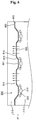
- Fig. 4 is an exploded perspective view illustrating the upper burner 500 and a reflector 700 of a gas oven range according to a second embodiment.
- the reflector 700 includes a reflection part 710, exhaust holes 730, fixing flanges 740, and cover parts 750.
- the reflection part 710 includes a plurality of first connection parts 711, oblique parts 713, and second connection parts 715.
- the reflector 700 further includes cover parts 750 as compared with the previous embodiment.
- the cover parts 750 are provided so that flames and heat generated by combustion of gas at the upper burner 500 can be prevented from flowing through the exhaust holes 730 to a space between the top surface of the reflector 700 and the ceiling of the oven chamber 211 (refer to Fig. 1 ). Furthermore, owing to the cover parts 750, combustion gas generated by combustion of gas at the upper burner 500 can be uniformly distributed through the space between the top surface of the reflector 700 and the ceiling of the oven chamber 211.
- the cover parts 750 have a plate shape with a size corresponding to the size of the exhaust holes 730.
- the cover parts 750 are disposed directly above the exhaust holes 730. Owing to this structure, flames and heat generated by combustion of gas at the upper burner 500 are not transferred through the exhaust holes 730 to the space between the top surface of the reflector 700 and the ceiling of the oven chamber 211 but are reflected by the cover parts 750 downwardly toward the inside of the oven chamber 211.
- combustion gas discharged through the exhaust holes 730 can be uniformly distributed forward, backward, leftward, and/or rightward by the cover parts 750.
- Fixing ribs 751 are provided at front and rear end portions of each cover part 750.
- the fixing ribs 751 are provided to fix the cover part 750 to the reflection part 710.
- the fixing ribs 751 have an approximate L-shape and disposed at the front and rear end portions of each cover part 750.
- the fixing ribs 751 and the cover part 750 may be formed in one piece.
- the cover part 750 and the reflector 700 may be formed in one piece.
- the exhaust hole 730 and the cover part 750 may be formed by forming two parallel lines in the second connection part 715 by cutting the second connection part 715 in the length direction of the second connection part 715, and upwardly bending a portion of the second connection part 715 disposed between the parallel lines.
- Fig. 5 is an exploded perspective view illustrating the upper burner 500 and the reflector 800 of the gas oven range according to a third embodiment
- Fig. 6 is a vertical sectional view illustrating reflection of flames and exhaustion of combustion gas at the reflector 800 according to the third embodiment.
- the reflector 800 includes a reflection part 810, compartment parts 820, exhaust holes 830, and fixing flanges 840.
- the reflection part 810 includes a plurality of first connection parts 811, oblique parts 813, and second connection parts 815.
- the reflector 800 further includes the compartment parts 820 as compared with the first and second embodiments.
- the compartment parts 820 are disposed between lateral surfaces of the oven chamber 211 and lateral end portions of the reflector 800 for more complete compartment.
- the oven chamber 211 is divided into a combustion space 215 and an exhaust space 213 by the reflector 800.
- the compartment parts 820 are provided on both sides of the reflector 800, that is, outer end portions of the oblique parts 813 of the reflection part 810.
- the compartment parts 820 extend outward from the outer end portions of the oblique parts 813 toward the lateral surfaces of the oven chamber 211.
- Outer end portions of the compartment parts 820 are placed close to the lateral surfaces of the oven chamber 211, respectively.
- the distance between the outer end portions of the compartment parts 820 and the lateral surfaces of the oven chamber 211 may be at least smaller than the width of the exhaust holes 830. Therefore, the combustion space 215 is formed by the lateral, rear, and bottom surfaces of the oven chamber 211 and the bottom surfaces of the reflector 800, and the exhaust space 213 is formed by the lateral, rear, and ceiling surfaces of the oven chamber 211 and the top surface of the reflector 800.
- the exhaust holes 830 are formed in the reflection part 810, specifically, in the second connection parts and the compartment parts 820. Combustion gas generated as a result of combustion of gas at the upper burner 500 is colleted between the upper burner 500 and the reflector 800, that is, at a space formed by the second connection part 815 and two oblique parts 813 connected to the second connection part 815, and then the combustion gas is discharged to the exhaust space 213 through the exhaust hole 830.
- the exhaust holes 620 are formed into an elongated shape by partially cutting out the second connection parts 815 and the compartment parts 820 of the reflection part 810 in a longitudinal direction thereof, i.e. in the preferred embodiment in a front-to-back direction.
- the reflection part 810 and the fixing flanges 840 of the reflector 800 have the same structures as those explained in the first and second embodiments. Thus, descriptions thereof will be omitted.
- Fig. 7 is a perspective view illustrating the upper burner 500 and the reflector 900 of the gas oven range according to a fourth second embodiment.
- the reflector 900 includes a reflection part 910, compartment parts 920, exhaust holes 930, fixing flanges 940, and cover parts 950.
- the reflection part 910 includes a plurality of first connection parts 911, oblique parts 913, and second connection parts 915.
- the reflector 900 further includes the cover parts 950 as compared with the third embodiment.
- the cover parts 950 are provided so that flames and heat, in particular radiant heat generated by combustion of gas at the upper burner 500 can be prevented from flowing from a lower side of the reflector 900 (that is, the combustion space 215) to a space (the exhaust space 213) formed between the top surface of the reflector 900 and the ceiling of the oven chamber 211 (refer to Fig. 3 ). Furthermore, owing to the cover parts 950, combustion gas generated by combustion of gas at the upper burner 500 can be uniformly distributed throughout the exhaust space 213.
- the cover parts 950 have a plate shape with a size corresponding to the size of the exhaust holes 930.
- the cover parts 950 are disposed directly above the exhaust holes 930. Owing to this structure, flames and heat generated by combustion of gas at the upper burner 500 are not transferred through the exhaust holes 930 to the upper side of the reflector 900 (that is, the exhaust space 213) but are reflected by the reflector 900 toward the lower side of the reflector 900 (that is, the combustion space 215).
- combustion gas discharged through the exhaust holes 930 can be uniformly distributed by the cover parts 950 forward, backward, leftward, and/or rightward inside the exhaust space 213.
- the reflection part 910 and the fixing flanges 940 of the reflector 900 have the same structures as those explained in the first and second embodiments. Thus, descriptions thereof will be omitted.
- incomplete combustion of gas at the burner can be prevented, and food can be efficiently cooked by heat generated by combustion of gas at the burner.
- the reflector and the gas oven range including the reflector can provide the following effects.
- combustion gas generated by combustion of gas at the upper burner is discharged to the space between the top surface of the reflector and the ceiling of the oven chamber through the exhaust holes of the reflector. Therefore, incomplete combustion at the upper burner can be prevented, and thus efficiency decrease and generation of harmful gases can be prevented.
- flames and heat generated by combustion of gas at the upper burner are not transferred to the space between the top surface of the reflector and the ceiling of the oven chamber through the exhaust holes of the reflector. Therefore, food can be cooked in the oven chamber more efficiently.
Landscapes
- Engineering & Computer Science (AREA)
- Chemical & Material Sciences (AREA)
- Combustion & Propulsion (AREA)
- Mechanical Engineering (AREA)
- General Engineering & Computer Science (AREA)
- Baking, Grill, Roasting (AREA)
Description
- The present invention relates to a cooking device, and more particularly, to a gas oven range including a reflector and to a reflector configured to reflect heat generated from a burner.
- Gas oven ranges are used for cooking foods using a gaseous fuel. Such a gas oven range includes an oven chamber in which food is cooked, and a burner configured to burn a gaseous fuel for cooking food accommodated in the oven chamber. The burner can be installed on the ceiling of the oven chamber for generating a flame by burning a gaseous fuel and heat food placed in the oven chamber by radiant heat from the flame.
US 5,078,121 A discloses a device for adjusting a reflecting angles of a grill, reflecting plate in a gas oven range including a casing, an oven room for objects for cooking, upper and lower grill burners disposed in said oven room, and two or more grill reflecting plates constituting a pair of wings and hingedly mounted on the ceiling of said oven room by a common hinge pin.
DE 11 37 847 shows a grill oven having an oven chamber, burners and a reflector disposed above the burners, comprising holes which allow combustion gas to pass through.EP 1 111 309 A1 -
DE 1 137 847 B1claims 1 and 3. - The object of the present invention is to provide a gas oven range having an improved gas combusting efficiency of a burner. during cooking
- Another object of the present invention is to provide a reflector configured to efficiently transfer heat generated by combustion of gas at a burner to food in an oven chamber of a gas oven range.
- According to the present invention, a gas oven range preferably includes: an oven chamber in which food is cooked; a burner inside the oven chamber; and a reflector configured to reflect flame and heat generated by combustion of gas at the burner. In particular the reflector is installed between the ceiling of the oven chamber and the burner to reflect the flame generated when a gaseous fuel is burned at the burner toward the inside of the oven chamber, i.e. toward food placed therein to be cooked. The reflector divides the oven chamber into a combustion space in which gas is burned by the burner and an exhaust space to which combustion gas generated by combustion of gas at the burner is discharged.
- A reflector includes: a reflection part configured to reflect flame and heat generated by combustion of gas at a burner; and an exhaust hole configured to discharge combustion gas generated by combustion of gas at the burner toward a side opposite to the burner. To install the reflector within an oven chamber of a gas oven range a fixing flange is provided that is configured to fix the reflection part to an oven chamber.
- Further the reflector for reflecting flame and heat generated by combustion of gas at a burner disposed at an oven chamber includes a structure for preventing flame and heat generated by combustion of gas at the burner from leaking upward through gaps between both lateral end portions of the reflector and lateral surfaces of the oven chamber.
- The reflector further includes compartment parts extending from both sides of the reflection part to positions close to or contacting lateral surfaces of the oven chamber. The compartment parts being configured to prevent flame and heat of the burner from leaking to a side opposite to the burner through gaps between lateral end portions of the compartment parts and the lateral surfaces of the oven chamber.
- The details of one or more embodiments are set forth in the accompanying drawings and the description below. Other features will be apparent from the description and drawings, and from the claims.
-
-
Fig. 1 is a perspective view illustrating a gas oven range according to a first embodiment. -
Fig. 2 is an exploded perspective view illustrating an upper burner and a reflector according to the first embodiment. -
Fig. 3 is a vertical sectional view illustrating reflection of flames and exhaustion of combustion gas at the reflector according to the first embodiment. -
Fig. 4 is a perspective view illustrating an upper burner and a reflector of a gas oven range according to a second embodiment. -
Fig. 5 is a perspective view illustrating an upper burner and a reflector of a gas oven range according to a third embodiment. -
Fig. 6 is a vertical sectional view illustrating reflection of flames and exhaustion of combustion gas at the reflector according to the third embodiment. -
Fig. 7 is a perspective view illustrating an upper burner and a reflector of a gas oven range according to a fourth second embodiment. - Hereinafter, a reflector and a gas oven range including the reflector will be explained in detail with reference to the accompanying drawings according to a first embodiment.
-
Fig. 1 is a perspective view illustrating agas oven range 1 according to a first embodiment, andFig. 2 is an exploded perspective view illustrating anupper burner 500 and areflector 600 according to the first embodiment. - Referring to
Fig. 1 , theoven range 1 includes a cooktop part 100, anoven part 200, adrawer part 300, and acontrol part 400. The cooktop part 100, theoven part 200, and thedrawer part 300 are disposed at upper, middle, and lower regions of amain body 10 of theoven range 1, respectively. Thecontrol part 400 is disposed on the top of themain body 10 at a rear edge portion corresponding to a rear side of the cooktop part 100. - In more detail, the cook
top part 100 includes a plurality of cook-top burners 110. Each of the cook-top burners 110 can generate a flame by burning a gaseous fuel to directly heat a container in which food is placed. A plurality ofknobs 120 are disposed on a front end portion of the cooktop part 100. Theknobs 120 are used to close, open, or adjust valves (not shown) for starting, stopping, or adjusting supply of a gaseous fuel to the cook-top burners 110. - The
oven part 200 includes anoven cavity 210 provided inside themain body 10. Anoven chamber 211 is provided in theoven cavity 210. In theoven chamber 211, food is cooked. A burner chamber (not shown) is provided in theoven cavity 210 under theoven chamber 211 to install a lower burner (not shown). - The
oven chamber 211 can be selectively closed and opened by using anoven door 220. Theoven door 220 is a pull-down door of which the top end can be rotated up and down about the lower end. Adoor handle 221 is provided on a front upper portion of theoven door 220 so that a user can easily rotate theoven door 220 using thedoor handle 221. - A container in which food is contained can be stored in the
drawer part 300 at a predetermined temperature. Thedrawer part 300 includes adrawer 310 in which a container can be placed. - A manipulation signal can be input (generated) through the
control part 400 for operating theoven range 1, specifically, at least one of the cooktop part 100, theoven part 200, and thedrawer part 300. In addition, thecontrol part 400 displays information about operational conditions of theoven range 1. -
Fig. 2 shows theupper burner 500 that is disposed at an upper side of theoven chamber 211. Theupper burner 500 is used to burn a gaseous fuel to directly heat food placed in theoven chamber 211 by radiant heat from above. In the current embodiment, theupper burner 500 includes threecombustion parts 510 that have a fork shape elongated in a left-to-right direction (not shown) or preferably in a front-to-back direction of theoven chamber 211. - Referring to
Figs. 2 and3 , thereflector 600 includes areflection part 610,exhaust holes 620, andfixing flanges 630. Thereflector 600 is disposed between the ceiling of theoven chamber 211 and theupper burner 500. When a gaseous fuel is burned at theupper burner 500, thereflector 600 reflects heat from flames downwardly toward food placed in theoven chamber 211. In addition, when a gaseous fuel is burned at theupper burner 500, combustion gas is guided by thereflector 600 to a space above thereflector 600, that is, between the ceiling of theoven chamber 211 and thereflector 600. - Flames and heat generated from the
upper burner 500 are guided and reflected toward food placed in theoven chamber 211 substantially by thereflection part 610. Thereflection part 610 is formed by bending a plate having a predetermined area in an approximate W-shape (cross sectional shape). In more detail, thereflection part 610 includes a plurality offirst connection parts 611,oblique parts 613, andsecond connection parts 615. - Each of the
first connection parts 611 has a predetermined lateral width and is located directly above thecombustion part 510 in parallel with the combustion part 510.The number of thefirst connection parts 611 is determined according to the number of thecombustion parts 510. Theoblique parts 613 are sloped upwardly from both sides of thefirst connection part 611 at a predetermined angle. Thesecond connection part 615 is disposed between neighboring two of theoblique parts 613 to connect ends of theoblique parts 613. When a gaseous fuel is burned at theupper burner 500, combustion gas is collected in a space formed by thesecond connection part 615 and twooblique parts 613 connected to thesecond connection part 615, and then discharged through the exhaust holes 620. - The fixing
flanges 630 are disposed on corners of the top surface of thereflection part 610. The fixingflanges 630 are used to fix thereflection part 610 to the ceiling of theoven chamber 211. The fixingflanges 630 may be formed at the corners of thereflection part 610 by cutting and upwardly bending thefirst connection parts 611 and theoblique parts 613. - When a gaseous fuel is burned at the
upper burner 500, combustion gas is collected between theupper burner 500 and thereflection part 610, that is, in spaces formed by thesecond connection part 615 and theoblique parts 613 connected to thesecond connection part 615. Then, the combustion gas is discharged to a space between the ceiling of theoven chamber 211 and thereflection part 610 through the exhaust holes 620. For this end, the exhaust holes 620 are formed into an elongated shape by partially cutting out thesecond connection parts 615 in longitudinal direction thereof, i.e. in the preferred embodiment ia a front-to-back direction. - Operations of the
reflector 600 and theoven range 1 including thereflector 600 will now be described with reference to the accompanying drawings according to the first embodiment. -
Fig. 3 is a vertical sectional view illustrating reflection of flames and exhaustion of combustion gas at thereflector 600 according to the first embodiment. - A user can input a manipulation signal by using the
control part 400 for cooking food using theoven part 200. If a manipulation signal is input through thecontrol part 400, the upper burner 500 (and the lower burner) is operated to cook food in theoven chamber 211. - In detail, gas and air are supplied to the
upper burner 500, and flames are generated by combustion of the gas and air. Then, food is cooked in theoven chamber 211 by flames and heat generated at theupper burner 500. At this time, thereflector 600 guides flames and reflects heat generated by combustion of gas at theupper burner 500 toward the food placed in theoven chamber 211. Thus, thereflector 600 reflects the heat radiated upwardly from the flames back the food located below the burner. In addition, since thereflector 600 guides and reflects the flames, it is heated by the flames directly and by the hot combustion gas. Therefore thereflector 600 also radiates heat toward to the food. - Meanwhile, combustion gas generated as a result of combustion of gas at the
upper burner 500 is guided to the space between the ceiling of theoven chamber 211 and thereflector 600 through thereflector 600. In more detail, the combustion gas is collected at the space formed by thesecond connection part 615 and twooblique parts 613 connected to thesecond connection part 615. Then, the collected combustion gas flows upward, that is, to the space between the ceiling of theoven chamber 211 and thereflection part 610 through theexhaust hole 620. - Therefore, when flames and heat generated by the
upper burner 500 are reflected by thereflection part 610 toward food placed in theoven chamber 211, incomplete combustion of gas at theupper burner 500 can be prevented, which may caused by combustion gas generated by combustion of the gas. Therefore, food placed in theoven chamber 211 can be cooked more efficiently by theupper burner 500, and incomplete combustion at theupper burner 500, which may result in harmful gases such as carbon monoxide, can be prevented. - Hereinafter, another reflector and a gas oven range including such reflector will be explained in detail with reference to the accompanying drawings according to a second embodiment.
-
Fig. 4 is an exploded perspective view illustrating theupper burner 500 and areflector 700 of a gas oven range according to a second embodiment. - Referring to
Fig. 4 , in the current embodiment, thereflector 700 includes areflection part 710, exhaust holes 730, fixingflanges 740, and coverparts 750. Thereflection part 710 includes a plurality offirst connection parts 711,oblique parts 713, andsecond connection parts 715. - That is, in the current embodiment, the
reflector 700 further includescover parts 750 as compared with the previous embodiment. Thecover parts 750 are provided so that flames and heat generated by combustion of gas at theupper burner 500 can be prevented from flowing through the exhaust holes 730 to a space between the top surface of thereflector 700 and the ceiling of the oven chamber 211 (refer toFig. 1 ). Furthermore, owing to thecover parts 750, combustion gas generated by combustion of gas at theupper burner 500 can be uniformly distributed through the space between the top surface of thereflector 700 and the ceiling of theoven chamber 211. - The
cover parts 750 have a plate shape with a size corresponding to the size of the exhaust holes 730. Thecover parts 750 are disposed directly above the exhaust holes 730. Owing to this structure, flames and heat generated by combustion of gas at theupper burner 500 are not transferred through the exhaust holes 730 to the space between the top surface of thereflector 700 and the ceiling of theoven chamber 211 but are reflected by thecover parts 750 downwardly toward the inside of theoven chamber 211. In addition, combustion gas discharged through the exhaust holes 730 can be uniformly distributed forward, backward, leftward, and/or rightward by thecover parts 750. - Fixing
ribs 751 are provided at front and rear end portions of eachcover part 750. The fixingribs 751 are provided to fix thecover part 750 to thereflection part 710. In the current embodiment, the fixingribs 751 have an approximate L-shape and disposed at the front and rear end portions of eachcover part 750. For example, the fixingribs 751 and thecover part 750 may be formed in one piece. Furthermore, thecover part 750 and thereflector 700 may be formed in one piece. In this case, theexhaust hole 730 and thecover part 750 may be formed by forming two parallel lines in thesecond connection part 715 by cutting thesecond connection part 715 in the length direction of thesecond connection part 715, and upwardly bending a portion of thesecond connection part 715 disposed between the parallel lines. - Hereinafter, another reflector and a gas oven range including the reflector will be explained in detail with reference to the accompanying drawings according to a third embodiment.
-
Fig. 5 is an exploded perspective view illustrating theupper burner 500 and thereflector 800 of the gas oven range according to a third embodiment, andFig. 6 is a vertical sectional view illustrating reflection of flames and exhaustion of combustion gas at thereflector 800 according to the third embodiment. - Referring to
Figs. 5 and6 , in the current embodiment, thereflector 800 includes areflection part 810,compartment parts 820, exhaust holes 830, and fixingflanges 840. Thereflection part 810 includes a plurality offirst connection parts 811,oblique parts 813, andsecond connection parts 815. - That is, in the current embodiment, the
reflector 800 further includes thecompartment parts 820 as compared with the first and second embodiments. Thecompartment parts 820 are disposed between lateral surfaces of theoven chamber 211 and lateral end portions of thereflector 800 for more complete compartment. In other words, substantially, theoven chamber 211 is divided into acombustion space 215 and an exhaust space 213 by thereflector 800. For this end, thecompartment parts 820 are provided on both sides of thereflector 800, that is, outer end portions of theoblique parts 813 of thereflection part 810. In more detail, thecompartment parts 820 extend outward from the outer end portions of theoblique parts 813 toward the lateral surfaces of theoven chamber 211. Outer end portions of thecompartment parts 820 are placed close to the lateral surfaces of theoven chamber 211, respectively. The distance between the outer end portions of thecompartment parts 820 and the lateral surfaces of theoven chamber 211 may be at least smaller than the width of the exhaust holes 830. Therefore, thecombustion space 215 is formed by the lateral, rear, and bottom surfaces of theoven chamber 211 and the bottom surfaces of thereflector 800, and the exhaust space 213 is formed by the lateral, rear, and ceiling surfaces of theoven chamber 211 and the top surface of thereflector 800. - The exhaust holes 830 are formed in the
reflection part 810, specifically, in the second connection parts and thecompartment parts 820. Combustion gas generated as a result of combustion of gas at theupper burner 500 is colleted between theupper burner 500 and thereflector 800, that is, at a space formed by thesecond connection part 815 and twooblique parts 813 connected to thesecond connection part 815, and then the combustion gas is discharged to the exhaust space 213 through theexhaust hole 830. For this end, the exhaust holes 620 are formed into an elongated shape by partially cutting out thesecond connection parts 815 and thecompartment parts 820 of thereflection part 810 in a longitudinal direction thereof, i.e. in the preferred embodiment in a front-to-back direction. - In the current embodiment, the
reflection part 810 and the fixingflanges 840 of thereflector 800 have the same structures as those explained in the first and second embodiments. Thus, descriptions thereof will be omitted. - Hereinafter, another reflector and a gas oven range including the reflector will be explained in detail with reference to the accompanying drawings according to a third embodiment.
-
Fig. 7 is a perspective view illustrating theupper burner 500 and thereflector 900 of the gas oven range according to a fourth second embodiment. - Referring to
Fig. 7 , in the current embodiment, thereflector 900 includes areflection part 910,compartment parts 920, exhaust holes 930, fixingflanges 940, and coverparts 950. Thereflection part 910 includes a plurality offirst connection parts 911,oblique parts 913, andsecond connection parts 915. - That is, in the current embodiment, the
reflector 900 further includes thecover parts 950 as compared with the third embodiment. Thecover parts 950 are provided so that flames and heat, in particular radiant heat generated by combustion of gas at theupper burner 500 can be prevented from flowing from a lower side of the reflector 900 (that is, the combustion space 215) to a space (the exhaust space 213) formed between the top surface of thereflector 900 and the ceiling of the oven chamber 211 (refer toFig. 3 ). Furthermore, owing to thecover parts 950, combustion gas generated by combustion of gas at theupper burner 500 can be uniformly distributed throughout the exhaust space 213. - The
cover parts 950 have a plate shape with a size corresponding to the size of the exhaust holes 930. Thecover parts 950 are disposed directly above the exhaust holes 930. Owing to this structure, flames and heat generated by combustion of gas at theupper burner 500 are not transferred through the exhaust holes 930 to the upper side of the reflector 900 (that is, the exhaust space 213) but are reflected by thereflector 900 toward the lower side of the reflector 900 (that is, the combustion space 215). In addition, combustion gas discharged through the exhaust holes 930 can be uniformly distributed by thecover parts 950 forward, backward, leftward, and/or rightward inside the exhaust space 213. - In the current embodiment, the
reflection part 910 and the fixingflanges 940 of thereflector 900 have the same structures as those explained in the first and second embodiments. Thus, descriptions thereof will be omitted. - According to the embodiments, incomplete combustion of gas at the burner can be prevented, and food can be efficiently cooked by heat generated by combustion of gas at the burner.
- As described above, the reflector and the gas oven range including the reflector can provide the following effects.
- According to the embodiments of the present disclosure, combustion gas generated by combustion of gas at the upper burner is discharged to the space between the top surface of the reflector and the ceiling of the oven chamber through the exhaust holes of the reflector. Therefore, incomplete combustion at the upper burner can be prevented, and thus efficiency decrease and generation of harmful gases can be prevented.
- In addition, according to the present disclosure, flames and heat generated by combustion of gas at the upper burner are not transferred to the space between the top surface of the reflector and the ceiling of the oven chamber through the exhaust holes of the reflector. Therefore, food can be cooked in the oven chamber more efficiently.
Claims (12)
- A gas oven range comprising:an oven chamber (211) in which food is cooked;an upper burner (500) inside the oven chamber (211); anda reflector (600; 700; 800; 900) disposed above the burner (500);the reflector comprisinga reflection part (610; 710; 810; 910) configured to reflect flame and heat generated by combustion of gas at the burner (500), andan exhaust hole (620; 730; 830; 930) configured to discharge combustion gas generated by combustion of gas at the burner (500) toward a side opposite to the burner (500);characterized bya cover part (750; 950) spaced apart from the exhaust hole (730; 930) in a direction where combustion gas is discharged through the exhaust hole (730; 930), the cover part (750, 950) is disposed directly above the exhaust hole (730; 930), and the cover part (750, 950) has a plate shape with a size corresponding to the size of the exhaust hole (730, 930),wherein fixing ribs (751, 951) are provided at front and rear end portions of each cover part (750, 950), andwherein the fixing ribs (751, 951) are provided to fix the cover part (750, 950) to the reflection part (710, 910).
- The gas oven range according to claim 1, wherein the reflector (600; 700; 800; 900) divides the oven chamber (211) into a combustion space (215) in which gas is burned by the burner (500) and an exhaust space (213) to which combustion gas generated by combustion of gas at the burner (500) is discharged.
- A reflector to be disposed above a burner for reflecting flame and heat generated by combustion of gas at the burner disposed in an oven chamber, the reflector comprising:a reflection part (610; 710; 810; 910) configured to reflect flame and heat generated by combustion of gas at a burner (500); andan exhaust hole (620; 730; 830; 930) configured to discharge combustion gas generated by combustion of gas at the burner (500) toward a side opposite to the burner (500);characterized bya cover part (750; 950) spaced apart from the exhaust hole (730; 930) in a direction where combustion gas is discharged through the exhaust hole (730; 930), the cover part (750; 950) is disposed directly above the exhaust hole (730; 930), and the cover part (750, 950) has a plate shape with a size corresponding to the size of the exhaust hole (730, 930),wherein fixing ribs (751, 951) are provided at front and rear end portions of each cover part (750, 950), andwherein the fixing ribs (751, 951) are provided to fix the cover part (750, 950) to the reflection part (710, 910).
- The reflector according to claim 3, further comprising a structure for preventing flame and heat generated by combustion of gas at the burner (500) from leaking upward through gaps between both lateral end portions of the reflection part (810; 910) and lateral surfaces of the oven chamber (211).
- The reflector according to claim 4, wherein the structure for preventing flame and heat from leaking upward comprises compartment parts (820; 920) extending from both sides of the reflection part (810; 910) to positions close to or contacting lateral surfaces of the oven chamber (211).
- The reflector according to any one of the claims 4 to 5, wherein the gaps between the lateral end portions of the compartment parts (820; 920) and the lateral surfaces of the oven chamber (211) are smaller than a width of the exhaust hole (830; 930) measured in the same direction.
- The reflector according to any one of the claims 3 to 6, wherein the exhaust hole (620; 720; 820; 920) is formed by cutting out the reflection part (610; 710; 810; 910) partially.
- The reflector according to claim 7, wherein the exhaust hole (830; 930) is formed by cutting out the compartment part (820; 920) partially.
- The reflector according to claim 3, wherein the cover part (750; 950) is a separate part fixed to the reflection part (710; 910), or the cover part and the reflection part are formed in one piece.
- The reflector according to any one of the claims 3 to 9, wherein the reflection part (610) comprises:at least one first connection part (611) to be located above a combustion part (510) of the burner (500); andat least two oblique parts (613) extending from both sides of the first connection part (611) in a direction opposite to the burner (500).
- The reflector according to claim 8, wherein the reflection part (610) further comprises a second connection part (615) configured to connect neighboring oblique parts (613).
- The reflector according to any one of the claims 3 to 11, wherein a fixing flange (640; 740; 840; 940) configured to fix the reflection part (610; 710; 810; 910) within an oven chamber is formed by bending a portion of the reflection part.
Applications Claiming Priority (1)
| Application Number | Priority Date | Filing Date | Title |
|---|---|---|---|
| KR1020080073540A KR101064849B1 (en) | 2008-07-28 | 2008-07-28 | Reflector and gas oven range including the same |
Publications (3)
| Publication Number | Publication Date |
|---|---|
| EP2161503A2 EP2161503A2 (en) | 2010-03-10 |
| EP2161503A3 EP2161503A3 (en) | 2013-04-03 |
| EP2161503B1 true EP2161503B1 (en) | 2018-12-19 |
Family
ID=41502192
Family Applications (1)
| Application Number | Title | Priority Date | Filing Date |
|---|---|---|---|
| EP09009720.5A Active EP2161503B1 (en) | 2008-07-28 | 2009-07-28 | Reflector and gas oven range comprising the same |
Country Status (2)
| Country | Link |
|---|---|
| EP (1) | EP2161503B1 (en) |
| KR (1) | KR101064849B1 (en) |
Families Citing this family (3)
| Publication number | Priority date | Publication date | Assignee | Title |
|---|---|---|---|---|
| KR101710202B1 (en) * | 2010-02-09 | 2017-02-24 | 엘지전자 주식회사 | Gas oven range |
| KR101969497B1 (en) | 2017-06-12 | 2019-04-16 | 엘지전자 주식회사 | Griddle apparatus and cooking appliance therewith |
| KR20220062851A (en) | 2020-11-09 | 2022-05-17 | 한국기술교육대학교 산학협력단 | apparatus and method for manufacturing of chlorine gas |
Citations (3)
| Publication number | Priority date | Publication date | Assignee | Title |
|---|---|---|---|---|
| JPS5332670U (en) * | 1976-08-27 | 1978-03-22 | ||
| US5101805A (en) * | 1990-05-25 | 1992-04-07 | Samsung Electronics Co., Ltd. | Gas cooker for oven and grill cooking |
| US5473980A (en) * | 1995-01-20 | 1995-12-12 | Carpenter; Olaf E. | Barbecue burner cover |
Family Cites Families (14)
| Publication number | Priority date | Publication date | Assignee | Title |
|---|---|---|---|---|
| US2164079A (en) * | 1936-01-10 | 1939-06-27 | Gas Products Corp | Gaseous fuel stove |
| US2415223A (en) * | 1943-06-12 | 1947-02-04 | Citizens Trust & Savings Bank | Radiant provided with triangular pyramidal projection |
| US2668527A (en) * | 1948-10-18 | 1954-02-09 | Chambers Corp | Broiler reflector shield |
| DE1137847B (en) * | 1956-08-22 | 1962-10-11 | Alfred Neff Dr | Grill burner for a gas stove equipped with a grill area and oven and roasting tube |
| BE649153A (en) * | 1963-06-11 | 1964-12-11 | ||
| US3357475A (en) * | 1966-06-27 | 1967-12-12 | Tappan Co | Gas burner assembly |
| KR920004980Y1 (en) * | 1990-05-18 | 1992-07-25 | 삼성전자 주식회사 | Grill reflector reflector for gas oven |
| KR100343985B1 (en) * | 1994-10-07 | 2002-10-25 | 린나이코리아 주식회사 | Reflector of grill for gas oven |
| KR970010365U (en) * | 1995-08-14 | 1997-03-29 | Burner structure of gas oven | |
| KR0133637Y1 (en) * | 1995-11-18 | 1999-03-20 | 배순훈 | Burner structure of gas oven |
| FR2803023B1 (en) * | 1999-12-23 | 2002-02-22 | Brandt Cooking | GAS OVEN |
| KR100425133B1 (en) | 2002-01-03 | 2004-03-31 | 엘지전자 주식회사 | burner for gas oven range |
| ITSV20020015A1 (en) | 2002-04-19 | 2003-10-20 | Cast Srl | BURNER FOR OVEN OR GRILL VENTURI TUBE BRACKET SUPPORTING A THERMOCOUPLE AND / OR A SPARK PLUG AND PROCEDURE FOR THE FAB |
| US20060048769A1 (en) * | 2004-09-09 | 2006-03-09 | Chien-Chang Lu | Roaster oven able to roast meat on both sides simultaneously |
-
2008
- 2008-07-28 KR KR1020080073540A patent/KR101064849B1/en active IP Right Grant
-
2009
- 2009-07-28 EP EP09009720.5A patent/EP2161503B1/en active Active
Patent Citations (3)
| Publication number | Priority date | Publication date | Assignee | Title |
|---|---|---|---|---|
| JPS5332670U (en) * | 1976-08-27 | 1978-03-22 | ||
| US5101805A (en) * | 1990-05-25 | 1992-04-07 | Samsung Electronics Co., Ltd. | Gas cooker for oven and grill cooking |
| US5473980A (en) * | 1995-01-20 | 1995-12-12 | Carpenter; Olaf E. | Barbecue burner cover |
Also Published As
| Publication number | Publication date |
|---|---|
| KR101064849B1 (en) | 2011-09-14 |
| EP2161503A2 (en) | 2010-03-10 |
| KR20100012245A (en) | 2010-02-08 |
| EP2161503A3 (en) | 2013-04-03 |
Similar Documents
| Publication | Publication Date | Title |
|---|---|---|
| US9021942B2 (en) | Cooker | |
| US9080774B2 (en) | Cooker | |
| CA2732369C (en) | Reflector and gas oven range comprising the same | |
| US9702564B2 (en) | Cooker | |
| US8764437B2 (en) | Burner and cooker including the burner | |
| EP2241819B1 (en) | Cooking device | |
| EP2161503B1 (en) | Reflector and gas oven range comprising the same | |
| EP2149750B1 (en) | Burner and gas oven including the same | |
| KR100938201B1 (en) | Burner and cooking appliance comprising the same | |
| US20120266861A1 (en) | Burner and cooker including the burner | |
| KR101067949B1 (en) | Reflector and gas oven range including the same | |
| KR101040404B1 (en) | Burners and Cookers | |
| KR101710202B1 (en) | Gas oven range | |
| JP7594947B2 (en) | Cooking equipment | |
| KR101040427B1 (en) | Reflector and gas oven range including the same | |
| KR101623981B1 (en) | Cooking appliance | |
| KR101665708B1 (en) | Gas oven range | |
| US9897323B2 (en) | Gas oven | |
| JP2023169511A (en) | Gas stove | |
| KR101690329B1 (en) | Cooking appliance | |
| CN119072263A (en) | Incinerator Systems for Advanced Grills | |
| KR101673603B1 (en) | Cooking appliance | |
| JP2022052146A (en) | Heating cooker | |
| JPH11216069A (en) | Double-broiling grill | |
| KR20110092492A (en) | Top burner and gas oven comprising the same |
Legal Events
| Date | Code | Title | Description |
|---|---|---|---|
| PUAI | Public reference made under article 153(3) epc to a published international application that has entered the european phase |
Free format text: ORIGINAL CODE: 0009012 |
|
| AK | Designated contracting states |
Kind code of ref document: A2 Designated state(s): AT BE BG CH CY CZ DE DK EE ES FI FR GB GR HR HU IE IS IT LI LT LU LV MC MK MT NL NO PL PT RO SE SI SK SM TR |
|
| AX | Request for extension of the european patent |
Extension state: AL BA RS |
|
| RIC1 | Information provided on ipc code assigned before grant |
Ipc: F24C 3/08 20060101AFI20120227BHEP Ipc: F24C 15/22 20060101ALI20120227BHEP |
|
| PUAL | Search report despatched |
Free format text: ORIGINAL CODE: 0009013 |
|
| AK | Designated contracting states |
Kind code of ref document: A3 Designated state(s): AT BE BG CH CY CZ DE DK EE ES FI FR GB GR HR HU IE IS IT LI LT LU LV MC MK MT NL NO PL PT RO SE SI SK SM TR |
|
| AX | Request for extension of the european patent |
Extension state: AL BA RS |
|
| RIC1 | Information provided on ipc code assigned before grant |
Ipc: F24C 15/22 20060101ALI20130226BHEP Ipc: F24C 3/08 20060101AFI20130226BHEP Ipc: F24C 15/24 20060101ALI20130226BHEP |
|
| 17P | Request for examination filed |
Effective date: 20130719 |
|
| RBV | Designated contracting states (corrected) |
Designated state(s): AT BE BG CH CY CZ DE DK EE ES FI FR GB GR HR HU IE IS IT LI LT LU LV MC MK MT NL NO PL PT RO SE SI SK SM TR |
|
| 17Q | First examination report despatched |
Effective date: 20160909 |
|
| STAA | Information on the status of an ep patent application or granted ep patent |
Free format text: STATUS: EXAMINATION IS IN PROGRESS |
|
| GRAP | Despatch of communication of intention to grant a patent |
Free format text: ORIGINAL CODE: EPIDOSNIGR1 |
|
| STAA | Information on the status of an ep patent application or granted ep patent |
Free format text: STATUS: GRANT OF PATENT IS INTENDED |
|
| INTG | Intention to grant announced |
Effective date: 20180621 |
|
| RAP1 | Party data changed (applicant data changed or rights of an application transferred) |
Owner name: LG ELECTRONICS INC. |
|
| GRAS | Grant fee paid |
Free format text: ORIGINAL CODE: EPIDOSNIGR3 |
|
| GRAJ | Information related to disapproval of communication of intention to grant by the applicant or resumption of examination proceedings by the epo deleted |
Free format text: ORIGINAL CODE: EPIDOSDIGR1 |
|
| GRAL | Information related to payment of fee for publishing/printing deleted |
Free format text: ORIGINAL CODE: EPIDOSDIGR3 |
|
| STAA | Information on the status of an ep patent application or granted ep patent |
Free format text: STATUS: EXAMINATION IS IN PROGRESS |
|
| GRAR | Information related to intention to grant a patent recorded |
Free format text: ORIGINAL CODE: EPIDOSNIGR71 |
|
| STAA | Information on the status of an ep patent application or granted ep patent |
Free format text: STATUS: GRANT OF PATENT IS INTENDED |
|
| INTC | Intention to grant announced (deleted) | ||
| GRAA | (expected) grant |
Free format text: ORIGINAL CODE: 0009210 |
|
| STAA | Information on the status of an ep patent application or granted ep patent |
Free format text: STATUS: THE PATENT HAS BEEN GRANTED |
|
| INTG | Intention to grant announced |
Effective date: 20181012 |
|
| AK | Designated contracting states |
Kind code of ref document: B1 Designated state(s): AT BE BG CH CY CZ DE DK EE ES FI FR GB GR HR HU IE IS IT LI LT LU LV MC MK MT NL NO PL PT RO SE SI SK SM TR |
|
| REG | Reference to a national code |
Ref country code: GB Ref legal event code: FG4D |
|
| REG | Reference to a national code |
Ref country code: CH Ref legal event code: EP |
|
| REG | Reference to a national code |
Ref country code: IE Ref legal event code: FG4D |
|
| REG | Reference to a national code |
Ref country code: DE Ref legal event code: R096 Ref document number: 602009056236 Country of ref document: DE |
|
| REG | Reference to a national code |
Ref country code: AT Ref legal event code: REF Ref document number: 1079149 Country of ref document: AT Kind code of ref document: T Effective date: 20190115 |
|
| REG | Reference to a national code |
Ref country code: NL Ref legal event code: MP Effective date: 20181219 |
|
| PG25 | Lapsed in a contracting state [announced via postgrant information from national office to epo] |
Ref country code: FI Free format text: LAPSE BECAUSE OF FAILURE TO SUBMIT A TRANSLATION OF THE DESCRIPTION OR TO PAY THE FEE WITHIN THE PRESCRIBED TIME-LIMIT Effective date: 20181219 Ref country code: LT Free format text: LAPSE BECAUSE OF FAILURE TO SUBMIT A TRANSLATION OF THE DESCRIPTION OR TO PAY THE FEE WITHIN THE PRESCRIBED TIME-LIMIT Effective date: 20181219 Ref country code: BG Free format text: LAPSE BECAUSE OF FAILURE TO SUBMIT A TRANSLATION OF THE DESCRIPTION OR TO PAY THE FEE WITHIN THE PRESCRIBED TIME-LIMIT Effective date: 20190319 Ref country code: HR Free format text: LAPSE BECAUSE OF FAILURE TO SUBMIT A TRANSLATION OF THE DESCRIPTION OR TO PAY THE FEE WITHIN THE PRESCRIBED TIME-LIMIT Effective date: 20181219 Ref country code: LV Free format text: LAPSE BECAUSE OF FAILURE TO SUBMIT A TRANSLATION OF THE DESCRIPTION OR TO PAY THE FEE WITHIN THE PRESCRIBED TIME-LIMIT Effective date: 20181219 Ref country code: NO Free format text: LAPSE BECAUSE OF FAILURE TO SUBMIT A TRANSLATION OF THE DESCRIPTION OR TO PAY THE FEE WITHIN THE PRESCRIBED TIME-LIMIT Effective date: 20190319 |
|
| REG | Reference to a national code |
Ref country code: LT Ref legal event code: MG4D |
|
| REG | Reference to a national code |
Ref country code: AT Ref legal event code: MK05 Ref document number: 1079149 Country of ref document: AT Kind code of ref document: T Effective date: 20181219 |
|
| PG25 | Lapsed in a contracting state [announced via postgrant information from national office to epo] |
Ref country code: SE Free format text: LAPSE BECAUSE OF FAILURE TO SUBMIT A TRANSLATION OF THE DESCRIPTION OR TO PAY THE FEE WITHIN THE PRESCRIBED TIME-LIMIT Effective date: 20181219 Ref country code: GR Free format text: LAPSE BECAUSE OF FAILURE TO SUBMIT A TRANSLATION OF THE DESCRIPTION OR TO PAY THE FEE WITHIN THE PRESCRIBED TIME-LIMIT Effective date: 20190320 |
|
| PG25 | Lapsed in a contracting state [announced via postgrant information from national office to epo] |
Ref country code: NL Free format text: LAPSE BECAUSE OF FAILURE TO SUBMIT A TRANSLATION OF THE DESCRIPTION OR TO PAY THE FEE WITHIN THE PRESCRIBED TIME-LIMIT Effective date: 20181219 |
|
| PG25 | Lapsed in a contracting state [announced via postgrant information from national office to epo] |
Ref country code: CZ Free format text: LAPSE BECAUSE OF FAILURE TO SUBMIT A TRANSLATION OF THE DESCRIPTION OR TO PAY THE FEE WITHIN THE PRESCRIBED TIME-LIMIT Effective date: 20181219 Ref country code: PT Free format text: LAPSE BECAUSE OF FAILURE TO SUBMIT A TRANSLATION OF THE DESCRIPTION OR TO PAY THE FEE WITHIN THE PRESCRIBED TIME-LIMIT Effective date: 20190419 Ref country code: ES Free format text: LAPSE BECAUSE OF FAILURE TO SUBMIT A TRANSLATION OF THE DESCRIPTION OR TO PAY THE FEE WITHIN THE PRESCRIBED TIME-LIMIT Effective date: 20181219 Ref country code: PL Free format text: LAPSE BECAUSE OF FAILURE TO SUBMIT A TRANSLATION OF THE DESCRIPTION OR TO PAY THE FEE WITHIN THE PRESCRIBED TIME-LIMIT Effective date: 20181219 |
|
| PG25 | Lapsed in a contracting state [announced via postgrant information from national office to epo] |
Ref country code: RO Free format text: LAPSE BECAUSE OF FAILURE TO SUBMIT A TRANSLATION OF THE DESCRIPTION OR TO PAY THE FEE WITHIN THE PRESCRIBED TIME-LIMIT Effective date: 20181219 Ref country code: SK Free format text: LAPSE BECAUSE OF FAILURE TO SUBMIT A TRANSLATION OF THE DESCRIPTION OR TO PAY THE FEE WITHIN THE PRESCRIBED TIME-LIMIT Effective date: 20181219 Ref country code: IS Free format text: LAPSE BECAUSE OF FAILURE TO SUBMIT A TRANSLATION OF THE DESCRIPTION OR TO PAY THE FEE WITHIN THE PRESCRIBED TIME-LIMIT Effective date: 20190419 Ref country code: SM Free format text: LAPSE BECAUSE OF FAILURE TO SUBMIT A TRANSLATION OF THE DESCRIPTION OR TO PAY THE FEE WITHIN THE PRESCRIBED TIME-LIMIT Effective date: 20181219 Ref country code: EE Free format text: LAPSE BECAUSE OF FAILURE TO SUBMIT A TRANSLATION OF THE DESCRIPTION OR TO PAY THE FEE WITHIN THE PRESCRIBED TIME-LIMIT Effective date: 20181219 |
|
| REG | Reference to a national code |
Ref country code: DE Ref legal event code: R097 Ref document number: 602009056236 Country of ref document: DE |
|
| PLBE | No opposition filed within time limit |
Free format text: ORIGINAL CODE: 0009261 |
|
| STAA | Information on the status of an ep patent application or granted ep patent |
Free format text: STATUS: NO OPPOSITION FILED WITHIN TIME LIMIT |
|
| PG25 | Lapsed in a contracting state [announced via postgrant information from national office to epo] |
Ref country code: DK Free format text: LAPSE BECAUSE OF FAILURE TO SUBMIT A TRANSLATION OF THE DESCRIPTION OR TO PAY THE FEE WITHIN THE PRESCRIBED TIME-LIMIT Effective date: 20181219 Ref country code: AT Free format text: LAPSE BECAUSE OF FAILURE TO SUBMIT A TRANSLATION OF THE DESCRIPTION OR TO PAY THE FEE WITHIN THE PRESCRIBED TIME-LIMIT Effective date: 20181219 |
|
| PGFP | Annual fee paid to national office [announced via postgrant information from national office to epo] |
Ref country code: IT Payment date: 20190726 Year of fee payment: 11 |
|
| 26N | No opposition filed |
Effective date: 20190920 |
|
| PG25 | Lapsed in a contracting state [announced via postgrant information from national office to epo] |
Ref country code: SI Free format text: LAPSE BECAUSE OF FAILURE TO SUBMIT A TRANSLATION OF THE DESCRIPTION OR TO PAY THE FEE WITHIN THE PRESCRIBED TIME-LIMIT Effective date: 20181219 Ref country code: MC Free format text: LAPSE BECAUSE OF FAILURE TO SUBMIT A TRANSLATION OF THE DESCRIPTION OR TO PAY THE FEE WITHIN THE PRESCRIBED TIME-LIMIT Effective date: 20181219 |
|
| REG | Reference to a national code |
Ref country code: CH Ref legal event code: PL |
|
| GBPC | Gb: european patent ceased through non-payment of renewal fee |
Effective date: 20190728 |
|
| PG25 | Lapsed in a contracting state [announced via postgrant information from national office to epo] |
Ref country code: TR Free format text: LAPSE BECAUSE OF FAILURE TO SUBMIT A TRANSLATION OF THE DESCRIPTION OR TO PAY THE FEE WITHIN THE PRESCRIBED TIME-LIMIT Effective date: 20181219 |
|
| REG | Reference to a national code |
Ref country code: BE Ref legal event code: MM Effective date: 20190731 |
|
| PG25 | Lapsed in a contracting state [announced via postgrant information from national office to epo] |
Ref country code: GB Free format text: LAPSE BECAUSE OF NON-PAYMENT OF DUE FEES Effective date: 20190728 |
|
| PG25 | Lapsed in a contracting state [announced via postgrant information from national office to epo] |
Ref country code: LU Free format text: LAPSE BECAUSE OF NON-PAYMENT OF DUE FEES Effective date: 20190728 Ref country code: CH Free format text: LAPSE BECAUSE OF NON-PAYMENT OF DUE FEES Effective date: 20190731 Ref country code: BE Free format text: LAPSE BECAUSE OF NON-PAYMENT OF DUE FEES Effective date: 20190731 Ref country code: LI Free format text: LAPSE BECAUSE OF NON-PAYMENT OF DUE FEES Effective date: 20190731 |
|
| PG25 | Lapsed in a contracting state [announced via postgrant information from national office to epo] |
Ref country code: FR Free format text: LAPSE BECAUSE OF NON-PAYMENT OF DUE FEES Effective date: 20190731 |
|
| PG25 | Lapsed in a contracting state [announced via postgrant information from national office to epo] |
Ref country code: IE Free format text: LAPSE BECAUSE OF NON-PAYMENT OF DUE FEES Effective date: 20190728 |
|
| PG25 | Lapsed in a contracting state [announced via postgrant information from national office to epo] |
Ref country code: CY Free format text: LAPSE BECAUSE OF FAILURE TO SUBMIT A TRANSLATION OF THE DESCRIPTION OR TO PAY THE FEE WITHIN THE PRESCRIBED TIME-LIMIT Effective date: 20181219 |
|
| PG25 | Lapsed in a contracting state [announced via postgrant information from national office to epo] |
Ref country code: MT Free format text: LAPSE BECAUSE OF FAILURE TO SUBMIT A TRANSLATION OF THE DESCRIPTION OR TO PAY THE FEE WITHIN THE PRESCRIBED TIME-LIMIT Effective date: 20181219 Ref country code: HU Free format text: LAPSE BECAUSE OF FAILURE TO SUBMIT A TRANSLATION OF THE DESCRIPTION OR TO PAY THE FEE WITHIN THE PRESCRIBED TIME-LIMIT; INVALID AB INITIO Effective date: 20090728 |
|
| PG25 | Lapsed in a contracting state [announced via postgrant information from national office to epo] |
Ref country code: IT Free format text: LAPSE BECAUSE OF NON-PAYMENT OF DUE FEES Effective date: 20200728 |
|
| PG25 | Lapsed in a contracting state [announced via postgrant information from national office to epo] |
Ref country code: MK Free format text: LAPSE BECAUSE OF FAILURE TO SUBMIT A TRANSLATION OF THE DESCRIPTION OR TO PAY THE FEE WITHIN THE PRESCRIBED TIME-LIMIT Effective date: 20181219 |
|
| PGFP | Annual fee paid to national office [announced via postgrant information from national office to epo] |
Ref country code: DE Payment date: 20240604 Year of fee payment: 16 |